JP2020171363A - Product advance tool - Google Patents
Product advance tool Download PDFInfo
- Publication number
- JP2020171363A JP2020171363A JP2019073375A JP2019073375A JP2020171363A JP 2020171363 A JP2020171363 A JP 2020171363A JP 2019073375 A JP2019073375 A JP 2019073375A JP 2019073375 A JP2019073375 A JP 2019073375A JP 2020171363 A JP2020171363 A JP 2020171363A
- Authority
- JP
- Japan
- Prior art keywords
- product
- substrate
- substrate portion
- long groove
- tool
- Prior art date
- Legal status (The legal status is an assumption and is not a legal conclusion. Google has not performed a legal analysis and makes no representation as to the accuracy of the status listed.)
- Pending
Links
Images






Landscapes
- Freezers Or Refrigerated Showcases (AREA)
Abstract
Description
本発明は、スーパーやコンビニの商品陳列に使用される基板上を前後移動する商品前出し体の設置安定性を高めた商品前出し具に関するものである。 The present invention relates to a product advance tool having improved installation stability of a product advance body that moves back and forth on a substrate used for displaying products in supermarkets and convenience stores.
量販店、コンビニ、スーパー等において、陳列された商品は陳列棚の手前の方から順次売れるため、時間がたつにつれ陳列棚の手前には商品が無くなったり、ごく少量になったりする。この場合、客は陳列棚の奥の方にある商品を見逃したり、何となく取り辛かったりして、購買意欲が急速に低下し商品の売れ行きに悪い影響を及ぼすことが多くなる。これを解決するため、作業者は、奥に残っている商品を手前に移し、その後方に新しい商品を補充する作業を頻繁に行うことになる。 At mass retailers, convenience stores, supermarkets, etc., the products displayed are sold in order from the front of the display shelves, so as time goes by, the products disappear or become very small in front of the display shelves. In this case, the customer often misses the product in the back of the display shelf or somehow finds it difficult to take it, which rapidly reduces the purchasing motivation and adversely affects the sales of the product. In order to solve this, the worker frequently moves the product remaining in the back to the front and replenishes the new product behind it.
しかしながら、新しい商品を後方の空間へ補充する作業は、前方にある商品が邪魔をして行い難い。また、奥にある商品を手前に移すのも大変な作業となっている。近年、このような新しい商品の補充を行い易くしたり、商品を常に前出し状態にする方法として、固定された商品陳列棚に商品前出し機能を有する商品前出し具を設置して、陳列商品を手動又は自動的に前に押し出すものが知られている。 However, the work of replenishing new products to the rear space is difficult because the products in front interfere with it. It is also a difficult task to move the products in the back to the front. In recent years, as a method of facilitating the replenishment of such new products and always keeping the products in the front-out state, a product front-loading tool having a product front-out function is installed on a fixed product display shelf to display the products. There are known ones that manually or automatically push forward.
例えば、WO2006/027872公報には、商品を陳列する基板と、該基板に載置され、自然状態において常に前方移動状態にある商品押圧板を備える商品前出し体と、を有し、該商品前出し体の底板の裏面又は該基板の上面のいずれか一方又は両方に滑り手段を付設し、更に該基板の前方部に、更に商品転落防止板を付設した商品自動前出し具が開示されている。この商品自動前出し具によれば、基板上に商品が前後方向に多量に並ぶ場合であっても、陳列商品を自動的に確実に前に送り出す作用力があり、作業者の前出し作業の労力を軽減すると共に、顧客にとっては商品が取り出し易いものとなる。 For example, WO2006 / 027872 gazette has a substrate for displaying products and a product front-out body provided with a product pressing plate which is placed on the substrate and is always in a forward moving state in a natural state. A product automatic front-out tool is disclosed in which a sliding means is attached to one or both of the back surface of the bottom plate of the output body and the upper surface of the substrate, and a product fall prevention plate is further attached to the front portion of the substrate. .. According to this automatic product advancement tool, even when a large number of products are lined up on the substrate in the front-rear direction, it has the action of automatically and surely sending out the displayed products forward, so that the worker can advance the products. It reduces labor and makes it easier for customers to take out products.
WO2007/20725公報には、商品を載置する基板と、該基板上に常に前方移動状態に置かれる自動商品押圧体と、該自動商品押圧体の後方に位置し、手動による引き出し操作により前方移動して該自動商品押圧体又は陳列商品を押し出す手動押圧体と、を有することを特徴とする商品前出し具が開示されている。この商品前出し具によれば、前出しが容易な商品は作業者等の手を煩わせることなく自動的に前出しができ、押出し力が弱く自動前出しができない商品にのみ、補助的に手動操作で前出しすることができる。このため、重量物や袋状物のようにはみ出し部がある商品であっても、それほどの労力をかけることなく、全ての陳列商品を確実に前出しできる。このため、あらゆる形状や重量の陳列商品が並ぶ商品陳列棚を整然とした前出し状態とすることができる。 According to WO2007 / 20725, a substrate on which a product is placed, an automatic product pressing body that is always placed in a forward moving state on the substrate, and an automatic product pressing body that is located behind the automatic product pressing body and moves forward by a manual pull-out operation. A product advance tool comprising the automatic product pressing body or a manual pressing body for pushing out a displayed product is disclosed. According to this product advance tool, products that are easy to advance can be automatically advanced without bothering workers, etc., and only products that have weak extrusion force and cannot be automatically advanced are supplemented. It can be moved forward manually. For this reason, even if the product has a protruding portion such as a heavy object or a bag-shaped object, all the displayed products can be reliably put forward without much effort. For this reason, the product display shelves on which display products of all shapes and weights are lined up can be put in an orderly front-out state.
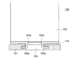
図15に示すように、特開2015-29875号公報などの従来の商品前出し具100は、基板110において、左右方向の中央の開口部105の両側の小基板101の内側の側面に形成された左右の係止溝104a、104bに、商品前出し体102の横L字形状の係止レール103a、103bが前後方向、移動自在に係止されている。このような商品前出し具100は、基板110の剛性が高いとは言えず、例えば、図16に示すように、左右の小基板106a、106bに対して、左右方向の外側に広がるような外力が作用すると、開口部105の開口幅が大となり、商品前出し体102は、基板110から外れるという問題があった。このような問題は、図15に示す係止構造に限定されず、中央の開口部を有する基板の全てにおいて生じる問題であった。
As shown in FIG. 15, the conventional
従って、本発明の目的は、基板の剛性を高め、商品前出し体が基板から外れ難く、設置安定性の高い商品前出し具を提供することにある。 Therefore, an object of the present invention is to increase the rigidity of the substrate, to prevent the product advance body from coming off the substrate, and to provide a product advance tool having high installation stability.
すなわち、本発明は、上記従来の課題を解決するものであって、設置面に載置される商品前出し具であって、設置面に載置されると共に、商品が載置される基板と、該基板上を前後に移動自在に取り付けられる基板部と、該基板部の後端から上方に延びる前方の商品を押圧する商品押圧板を備える商品前出し体と、を有し、該基板は、左右方向の中央で前後方向に延びる開口部により形成される左右の小基板と、該左の小基板又は該右の小基板の裏面に形成される前後方向に延びる長溝と、を有し、該商品前出し体の基板部は、該商品押圧板が付設される上部基板部と、該上部基板部の裏面から下方に延び次いで横方向外側に屈曲して延びる左右一対の下部基板部と、を有し、該左の下部基板部又は該右の下部基板部には、該長溝に係止する係止突起が形成され、該左右の小基板の内側の角部が、該上部基板部と該下部基板部間に挿通され、該係止突起が該長溝に係止して、該商品前出し体が基板に対して前後移動自在に係止することを特徴とする商品前出し具を提供するものである。 That is, the present invention solves the above-mentioned conventional problems, and is a product front-out tool mounted on an installation surface, and is a substrate on which a product is placed while being mounted on the installation surface. The substrate includes a substrate portion that can be movably mounted on the substrate back and forth, and a product front-out body that includes a product pressing plate that presses a front product extending upward from the rear end of the substrate portion. It has left and right small substrates formed by openings extending in the front-rear direction at the center in the left-right direction, and long grooves extending in the front-rear direction formed on the back surface of the left small substrate or the right small substrate. The substrate portion of the product front part includes an upper substrate portion to which the product pressing plate is attached, a pair of left and right lower substrate portions extending downward from the back surface of the upper substrate portion, and then bending outward in the lateral direction. On the left lower substrate portion or the right lower substrate portion, a locking projection for locking to the long groove is formed, and the inner corner portions of the left and right small substrates form the upper substrate portion. Provided is a product advance tool, which is inserted between the lower substrate portions, the locking projection is locked in the long groove, and the product advance body is movably locked with respect to the substrate. Is what you do.
また、本発明は、該長溝は、該開口部の近傍に付設されることを特徴とする前記商品前出し具を提供するものである。 Further, the present invention provides the product advance tool, wherein the long groove is provided in the vicinity of the opening.
また、本発明は、該基板の裏面で、且つ該長溝の左右方向の外側に凹部を形成し、該凹部を形成することで得られる該長溝と該凹部間に前後方向に延びる補強突起壁を、更に有することを特徴とする前記商品前出し具を提供するものである。 Further, in the present invention, a recess is formed on the back surface of the substrate and on the outer side of the elongated groove in the left-right direction, and a reinforcing protrusion wall extending in the front-rear direction is formed between the elongated groove and the recess obtained by forming the recess. Further, the present invention provides the above-mentioned product advance tool, which is characterized by having.
また、本発明は、該長溝は、天面を有し下方が開口する矩形断面形状であることを特徴とする前記商品前出し具を提供するものである。 The present invention also provides the above-mentioned product front-out tool, characterized in that the elongated groove has a rectangular cross-sectional shape having a top surface and an opening at the bottom.
また、本発明は、該係止突起は、該左の下部基板部又は該右の下部基板部の上面又は端部から上方に起立する小突起であることを特徴とする前記商品前出し具を提供するものである。 Further, the present invention is characterized in that the locking protrusion is a small protrusion that stands upward from the upper surface or the end portion of the left lower substrate portion or the right lower substrate portion. It is to provide.
また、本発明は、該基板又は該基板の一方の側端から起立した側板に前後移動自在に付設される、該商品前出し体を前方に引き出す引き出し体と、を有することを特徴とする前記商品前出し具を提供するものである。 Further, the present invention is characterized by having a drawer body for pulling out the product front-out body forward, which is attached to the substrate or a side plate standing up from one side end of the substrate so as to be movable back and forth. It provides a product advance tool.
本発明によれば、基板を構成する左右の小基板のいずれか又は両方の裏面に長手方向に延びる長溝を形成し、この長溝に商品前出し体の下部基板部の係止突起が係止するようにしたため、基板と商品前出し体の係止箇所が増えると共に、長溝を構成する縦壁が、補強リブの機能を果たし、基板の剛性が高まる。このため、商品前出し体が基板から外れ難く、設置安定性の高い商品前出し具を提供できる。 According to the present invention, a long groove extending in the longitudinal direction is formed on the back surface of either or both of the left and right small boards constituting the board, and the locking projection of the lower board portion of the product front product is locked in this long groove. As a result, the number of places where the substrate and the product front product are locked increases, and the vertical wall forming the long groove functions as a reinforcing rib, increasing the rigidity of the substrate. For this reason, it is possible to provide a product advance tool having high installation stability because the product advance body does not easily come off from the substrate.
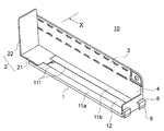
次に、本発明の実施の形態における商品前出し具を図1〜図14を参照して説明する。本明細書中、「前後」、「上下」及び「左右」は、設置面に設置された状態における顧客側を正面とした方向又は位置を言う。商品前出し具10は、設置面に載置されるものであって、基板1と、商品前出し体2と、引き出し体3と、側板4を有する。
Next, the product advance tool according to the embodiment of the present invention will be described with reference to FIGS. 1 to 14. In the present specification, "front and back", "up and down", and "left and right" refer to a direction or position with the customer side as the front when installed on the installation surface. The product front-out
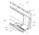
商品前出し具10において、基板1は、設置面に載置されると共に、商品が載置されるものを言う。基板1は、図5及び図6に示すように、中尺状の板状体の左右方向の中央で前後方向に延びる開口部12を形成することにより形成されたものであり、左の小基板11aと右の小基板11bを備え、両小基板11a、11bの内側角部がガイドレール111となるものである。また、基板1の一方の側端から起立した側板4が形成され、側板4の上部には、基板1の前後長さと略同じ長さの中尺板状の引き出し体3を前後方向に移動自在にガイドするガイド溝411(第2ガイドレール)が形成されている。ガイド溝411の前後方向に所定のピッチで多数形成される扁平台形状の貫通孔は、引き出し体3の引き出しに伴う摩擦を低減するための孔である。
In the
商品前出し具10において、基板1の前端には、商品の転落を防止する高さの低い起立状の転落防止板8が形成され、転落防止板8の前面には、商品前出し具10を、例えば棚板の前レールに固定するための係止片9が形成されている。また、基板1の後端で左右方向の中央には、バネ部材であるコイルバネ7の一端(後端)を固定するバネ第1係止部113が形成されている。コイルバネ7は、基板1と引き出し体3を接続し、引き出し体3は、引き出す際、コイルバネ7のバネ力に抗して引き出され、手を放すことで、引き出し体は元の位置に自動的に、復帰する。
In the
商品前出し具10において、基板1の左の小基板11aの裏面には、天面を有し下方が開口する前後方向に延びる略矩形断面形状の長溝16が形成されている。長溝16には、商品前出し体2の基板部21の裏面に形成される下部基板部212aの係止突起214が係止し、基板1に剛性を与えると共に、基板1に対する商品前出し体2の係止安定性を高め、商品前出し体2が脱落しないようにしている。
In the
長溝16は、開口部12の近傍に付設されることが、長溝16と開口部12間に位置する前後方向に延びる第1突起壁115が補強用のリブとして機能する点で、好ましい。また、図14に示すように、長溝16の左右方向の外側に凹部17を形成することで、長溝16と凹部17間に位置する前後方向に延びる第2突起壁(補強突起壁)116が補強用のリブとして機能する点で、好ましい。
It is preferable that the
商品前出し具10において、商品前出し体2は、基板1上又は基板1中を前後に移動自在に取り付けられる基板部21と、基板部21の後端から上方又はやや後方傾斜状に延びる前方の商品を押圧する商品押圧板22を備えるものである。基板部21の裏面には、引き出し体3と当接する第1当接部24を有する。これにより、商品前出し体2は、引き出し体3と基板の裏面で当接する。
In the product front-out
商品前出し体2は、具体的には、図7及び図8に示すように、商品押圧板22が付設される上部基板部211と、上部基板部211の裏面から下方に延び次いで横方向外側に屈曲して延びる左右一対の下部基板部212a、212bと、を有する。これにより、上部基板部211と左右一対の下部基板部212a、212b間の隙間213a、213bに、基板1のガイドレール111が係止することができる。
Specifically, as shown in FIGS. 7 and 8, the product front-out
商品前出し体2において、左側の下部基板部212aの左側の先端には、該先端から上方に少し起立し、下部基板部212aの前後方向に延びる係止突起214が形成されている。この係止突起214は、基板1の裏面に形成された長溝16に係止し、基板1から商品前出し体2が脱落しないような安定な係止を実現する。また、右側の下部基板部212bは、前後方向長さ途中で、切り欠かれており、下部基板部212aの長さの半分程度の長さとなっている。これにより、下部基板部212bの後端には、第1当接部24が形成されることになる。第1当接部24は、斜め傾斜面を有する凹面を形成しており、引き出し体3の第2当接部212bと当接することで、商品前出し体2と引き出し体3の接続(当接)が可能となる。また、下部基板部212bの前後方向の長さを短くすることで、第1当接部24が、商品押圧板22より、前方に位置することになり、商品前出し体2を前方側から引っ張ることができ、商品前出し体2の前方移動が円滑となる。また、商品前出し具10において、下部基板部212a、212bは、基板1より下方に突出する部分がなく、前後移動する際、下部基板部212a、212bが障害となることはない。
In the product front-out
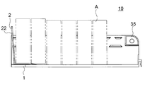
商品前出し具10において、引き出し体3は、側板4の前後方向に延びるガイド溝(第2ガイドレール)411に前後に移動自在に係止する引き出し体本体部31と、基板1の裏側に配設される係止板状体32と、引き出し本体31部と係止板状体32を接続する側板4の外側に配設される外側連結帯部33とを有し、係止板状体32の前端部が、第2当接部34となる。外側連結帯部33と係止板状体32は、背面視で略L字断面形状となっている。引き出し体本体部31は、中尺状の板状体であり、先端には、把持部39が形成さている。また、外側連結帯部33は、引き出し体本体部31の後方部の下端から下方に延びる略板状体である。本例の外側連結帯部33は、前後方向の中央部を基板1の側板4と接触しない凹部とすることで、摩擦抵抗を低減している。また、係止板状体32の前端の左端には、コイルバネ7の他端(前端)を固定するバネ第2係止部35が付設され、係止板状体32の前端の右半分には、係止板状体32より起立する小突起37が形成されている。なお、符号36は係止板状体32の後端の左端において起立する小突起であり、基板1の裏面に形成された溝レールに前後移動自在に係止し、引き出し体3の引き出し操作を円滑にする。すなわち、外側連結帯部33は板状体であり、上端が前方へ引っ張られるため、捻じれが生じて、側板との摩擦抵抗が大きくなる傾向にあり、小突起36は、この捻じれを防止する機能を果たす。第2当接部34は、バネ第2係止部35と小突起37の間に位置する、係止板状体32の先端部であり、該第1当接部24の当接面(凹面)に対応する凹面を有する。
In the
商品前出し具10において、商品前出し体2の基板部21の裏面の第1当接部24と、引き出し体3の第2当接部34は、該商品押圧板22より前方位置で当接しており、引き出し体3を前方へ引き出すことで、商品前出し体2が前方へ引き出され、商品押圧板22の前方に位置する載置商品が前出しされる。また、商品前出し具10は、図14に示すように、商品前出し体2の基板部21の裏面の第1当接部24と、引き出し体3の第2当接部34を、商品押圧板22より前方位置の当接位置としたため、待機状態において、商品押圧板22を基板1の後方端近傍とすることができる。このため、商品押圧板22の後方のデッドスペースを無くし、基板1上の載置商品の設置スペースを大きくでき、陳列効率を高めることができる。
In the
次に、商品前出し具10の使用方法について図12及び図13を参照して説明する。商品前出し具10において、商品押圧板22の前方には載置商品Aが陳列されている。載置商品Aは、基板1上に載っている。この際、引き出し体3は、コイルバネ7により、待機状態である基板1と同化するかのように、奥側に収容されている。商品群は前方の商品が売れることで、前方にスペースができる。この場合、顧客は、引き出し体3を把持して前方に引き出し、前方の商品を取ることができる。あるいは、作業者は、引き出し体3を前方に引き出し、手を放して、引き出し体3を自動的に、元の位置に復帰させ、最後尾の商品と商品押圧板22の間のスペースに商品を補充することができる。
Next, a method of using the
本発明は、上記実施の形態例に限定されず、種々の変形を採ることができる。商品前出し具10において、基板1と商品前出し体2が必須の構成要素であり、側板4、引き出し体3、コイルバネ7及び引き出し体3と商品前出し体2を接続する外側連結帯部33は、任意の構成要素であり、省略できる。すなわち、コイルバネ7を省略した場合、手動で引き出しができる。これにより、引き出し体3を手前に引き出した後は手動で引き出し体3を元に位置に戻すことになる。商品前出し具10において、側板4の高さは低くてもよく、実質的に、側板4の無いものであってもよい。商品前出し具10において、商品押圧板22を背後から前方へ押す押す部を設置し、この押す部に引き出し体3が接続されていてもよい。この場合、外側連結帯部33、第1当接部及び第2当接部は不要であり、例えば、図15に示すように、左右の小基板11a、11bは対称形とすることができる。この場合、長溝16は、右の小基板11bに形成してもよく、左右の小基板11a、11bの双方に形成してもよい。係止突起214は、下部基板部212aの外側先端に付設される以外、下部基板部212aの面上であってもよい。この係止突起214は、右の下部基板部212bに付設する場合も、同様に、先端又は基板部の上面であってもよい。
The present invention is not limited to the above-described embodiment, and various modifications can be taken. In the product front-out
本発明によれば、基板を構成する左右の小基板のいずれか又は両方の裏面に長手方向に延びる長溝を形成し、この長溝に商品前出し体の下部基板部の係止突起が係止するようにしたため、基板と商品前出し体の係止箇所が増えると共に、長溝を構成する縦壁が、補強リブの機能を果たし、基板の剛性が高まる。このため、商品前出し体が基板から外れ難く、設置安定性の高い商品前出し具を提供できる。 According to the present invention, a long groove extending in the longitudinal direction is formed on the back surface of either or both of the left and right small boards constituting the board, and the locking projection of the lower board portion of the product front product is locked in this long groove. As a result, the number of places where the substrate and the product front product are locked increases, and the vertical wall forming the long groove functions as a reinforcing rib, increasing the rigidity of the substrate. For this reason, it is possible to provide a product advance tool having high installation stability because the product advance body does not easily come off from the substrate.
1 基板
2 商品前出し体
3 引き出し体
4 側板
6 長溝
7 コイルバネ(バネ部材)
8 転落防止板
7 コイルバネ(バネ部材)
10 商品前出し具
11a 左の小基板
11b 右の小基板
21 基板部
22 商品押圧板
211 上部基板部
212(212a、212b) 下部基板部
1
8
10
Claims (6)
設置面に載置されると共に、商品が載置される基板と、
該基板上を前後に移動自在に取り付けられる基板部と、該基板部の後端から上方に延びる前方の商品を押圧する商品押圧板を備える商品前出し体と、を有し、
該基板は、左右方向の中央で前後方向に延びる開口部により形成される左右の小基板と、該左の小基板又は該右の小基板の裏面に形成される前後方向に延びる長溝と、を有し、
該商品前出し体の基板部は、該商品押圧板が付設される上部基板部と、該上部基板部の裏面から下方に延び次いで横方向外側に屈曲して延びる左右一対の下部基板部と、を有し、
該左の下部基板部又は該右の下部基板部には、該長溝に係止する係止突起が形成され、該左右の小基板の内側の角部が、該上部基板部と該下部基板部間に挿通され、該係止突起が該長溝に係止して、該商品前出し体が基板に対して前後移動自在に係止することを特徴とする商品前出し具。 It is a product front-out tool that is placed on the installation surface.
On the board on which the product is placed as well as on the installation surface,
It has a substrate portion that can be movably mounted on the substrate back and forth, and a product front part having a product pressing plate that presses a front product extending upward from the rear end of the substrate portion.
The substrate includes left and right small substrates formed by an opening extending in the front-rear direction at the center in the left-right direction, and long grooves extending in the front-rear direction formed on the back surface of the left small substrate or the right small substrate. Have and
The substrate portion of the product front-out body includes an upper substrate portion to which the product pressing plate is attached, and a pair of left and right lower substrate portions extending downward from the back surface of the upper substrate portion and then bending outward in the lateral direction. Have,
Locking projections for locking to the long groove are formed on the left lower substrate portion or the right lower substrate portion, and the inner corners of the left and right small substrates are the upper substrate portion and the lower substrate portion. A product front-out tool, which is inserted between them, and the locking projection is locked in the long groove, so that the product front-out body is movably locked with respect to a substrate.
Priority Applications (1)
| Application Number | Priority Date | Filing Date | Title |
|---|---|---|---|
| JP2019073375A JP2020171363A (en) | 2019-04-08 | 2019-04-08 | Product advance tool |
Applications Claiming Priority (1)
| Application Number | Priority Date | Filing Date | Title |
|---|---|---|---|
| JP2019073375A JP2020171363A (en) | 2019-04-08 | 2019-04-08 | Product advance tool |
Publications (1)
| Publication Number | Publication Date |
|---|---|
| JP2020171363A true JP2020171363A (en) | 2020-10-22 |
Family
ID=72830496
Family Applications (1)
| Application Number | Title | Priority Date | Filing Date |
|---|---|---|---|
| JP2019073375A Pending JP2020171363A (en) | 2019-04-08 | 2019-04-08 | Product advance tool |
Country Status (1)
| Country | Link |
|---|---|
| JP (1) | JP2020171363A (en) |
Citations (5)
| Publication number | Priority date | Publication date | Assignee | Title |
|---|---|---|---|---|
| JPH0537155U (en) * | 1991-10-24 | 1993-05-21 | 日本軽金属株式会社 | Partition structure |
| JP2000184919A (en) * | 1998-12-24 | 2000-07-04 | Nippon Filing Co Ltd | Shelf divider |
| JP2004194826A (en) * | 2002-12-17 | 2004-07-15 | Matsushita Electric Works Ltd | Draining basket for kitchen sink and attaching structure therefor |
| WO2007020725A1 (en) * | 2005-08-15 | 2007-02-22 | Kawajun Co., Ltd. | Merchandise advancing device |
| JP2007236650A (en) * | 2006-03-09 | 2007-09-20 | Okumoto Mokkosho:Kk | Learning desk |
-
2019
- 2019-04-08 JP JP2019073375A patent/JP2020171363A/en active Pending
Patent Citations (5)
| Publication number | Priority date | Publication date | Assignee | Title |
|---|---|---|---|---|
| JPH0537155U (en) * | 1991-10-24 | 1993-05-21 | 日本軽金属株式会社 | Partition structure |
| JP2000184919A (en) * | 1998-12-24 | 2000-07-04 | Nippon Filing Co Ltd | Shelf divider |
| JP2004194826A (en) * | 2002-12-17 | 2004-07-15 | Matsushita Electric Works Ltd | Draining basket for kitchen sink and attaching structure therefor |
| WO2007020725A1 (en) * | 2005-08-15 | 2007-02-22 | Kawajun Co., Ltd. | Merchandise advancing device |
| JP2007236650A (en) * | 2006-03-09 | 2007-09-20 | Okumoto Mokkosho:Kk | Learning desk |
Similar Documents
| Publication | Publication Date | Title |
|---|---|---|
| JP2000350642A (en) | Product display | |
| JPH11313737A (en) | Product dividers for display shelves | |
| JP4931817B2 (en) | Product advancement tool | |
| JPWO2006027871A1 (en) | Automatic product shelf unit | |
| JP2020092777A (en) | Slide shelf board and merchandise display rack | |
| JP6172801B2 (en) | Product advance device | |
| JP3205996U (en) | Product display tools | |
| JP4761366B2 (en) | Sliding product display shelf | |
| WO2006028246A1 (en) | Automatic merchandise advancing device | |
| JP2016187480A (en) | Product drawing device | |
| WO2006027872A1 (en) | Automatic item pushing forward device | |
| JP7253234B2 (en) | Product forwarding tool | |
| JP7202746B2 (en) | Sliding shelves and product display shelves | |
| JP3202584U (en) | Product display tools | |
| JP2009201711A (en) | Merchandise display shelf | |
| JP7106107B2 (en) | Product forwarding tool | |
| JP2020103337A (en) | Shelving | |
| JP2006087777A (en) | Slidable merchandise display shelf | |
| KR101715081B1 (en) | Tray escape prevention lever is equipped with a sliding rail | |
| JP3236029U (en) | Product advance device | |
| JP2017093959A (en) | Product divider | |
| JPWO2006028245A1 (en) | Automatic product shelf unit | |
| JP6607753B2 (en) | Furniture | |
| JP6986423B2 (en) | Shelf equipment | |
| JP3202567U (en) | Product advancement tool |
Legal Events
| Date | Code | Title | Description |
|---|---|---|---|
| A621 | Written request for application examination |
Free format text: JAPANESE INTERMEDIATE CODE: A621 Effective date: 20220324 |
|
| A131 | Notification of reasons for refusal |
Free format text: JAPANESE INTERMEDIATE CODE: A131 Effective date: 20230228 |
|
| A977 | Report on retrieval |
Free format text: JAPANESE INTERMEDIATE CODE: A971007 Effective date: 20230228 |
|
| A02 | Decision of refusal |
Free format text: JAPANESE INTERMEDIATE CODE: A02 Effective date: 20230829 |