JP2020056294A - Padding tool and padding method - Google Patents
Padding tool and padding method Download PDFInfo
- Publication number
- JP2020056294A JP2020056294A JP2019151417A JP2019151417A JP2020056294A JP 2020056294 A JP2020056294 A JP 2020056294A JP 2019151417 A JP2019151417 A JP 2019151417A JP 2019151417 A JP2019151417 A JP 2019151417A JP 2020056294 A JP2020056294 A JP 2020056294A
- Authority
- JP
- Japan
- Prior art keywords
- hole
- hole filling
- main body
- head
- tool
- Prior art date
- Legal status (The legal status is an assumption and is not a legal conclusion. Google has not performed a legal analysis and makes no representation as to the accuracy of the status listed.)
- Granted
Links
- 238000000034 method Methods 0.000 title claims abstract description 18
- 239000007788 liquid Substances 0.000 claims description 4
- 230000002093 peripheral effect Effects 0.000 claims description 4
- 238000010586 diagram Methods 0.000 abstract description 12
- 238000007789 sealing Methods 0.000 description 7
- 239000000463 material Substances 0.000 description 5
- 239000011347 resin Substances 0.000 description 5
- 229920005989 resin Polymers 0.000 description 5
- 229920000122 acrylonitrile butadiene styrene Polymers 0.000 description 4
- XECAHXYUAAWDEL-UHFFFAOYSA-N acrylonitrile butadiene styrene Chemical compound C=CC=C.C=CC#N.C=CC1=CC=CC=C1 XECAHXYUAAWDEL-UHFFFAOYSA-N 0.000 description 3
- 239000004676 acrylonitrile butadiene styrene Substances 0.000 description 3
- 229920000915 polyvinyl chloride Polymers 0.000 description 3
- 239000004800 polyvinyl chloride Substances 0.000 description 3
- 239000011248 coating agent Substances 0.000 description 2
- 238000000576 coating method Methods 0.000 description 2
- 230000007423 decrease Effects 0.000 description 2
- 230000008595 infiltration Effects 0.000 description 2
- 238000001764 infiltration Methods 0.000 description 2
- 239000004570 mortar (masonry) Substances 0.000 description 2
- 238000012856 packing Methods 0.000 description 2
- 239000004743 Polypropylene Substances 0.000 description 1
- 239000000853 adhesive Substances 0.000 description 1
- 230000001070 adhesive effect Effects 0.000 description 1
- 238000005452 bending Methods 0.000 description 1
- 239000011449 brick Substances 0.000 description 1
- 230000000694 effects Effects 0.000 description 1
- 229920001971 elastomer Polymers 0.000 description 1
- 230000002349 favourable effect Effects 0.000 description 1
- 230000001771 impaired effect Effects 0.000 description 1
- 238000003780 insertion Methods 0.000 description 1
- 230000037431 insertion Effects 0.000 description 1
- JEIPFZHSYJVQDO-UHFFFAOYSA-N iron(III) oxide Inorganic materials O=[Fe]O[Fe]=O JEIPFZHSYJVQDO-UHFFFAOYSA-N 0.000 description 1
- 238000012986 modification Methods 0.000 description 1
- 230000004048 modification Effects 0.000 description 1
- 238000000465 moulding Methods 0.000 description 1
- 238000010422 painting Methods 0.000 description 1
- -1 polypropylene Polymers 0.000 description 1
- 229920001155 polypropylene Polymers 0.000 description 1
- 239000005060 rubber Substances 0.000 description 1
- 238000007711 solidification Methods 0.000 description 1
- 230000008023 solidification Effects 0.000 description 1
- XLYOFNOQVPJJNP-UHFFFAOYSA-N water Substances O XLYOFNOQVPJJNP-UHFFFAOYSA-N 0.000 description 1
Images




Landscapes
- Working Measures On Existing Buildindgs (AREA)
Abstract
【課題】建築物の外壁の穴を容易に埋めて建築物の外観を良好に保つことができる穴埋め具及び穴埋め方法を提供することにある。【解決手段】建築物の外壁に形成された足場固定用のねじ穴に打ち込み、該ねじ穴を埋める穴埋め具であって、外径が小さくなるように変形する軸状の本体部と、該本体部の一端部に連なる頭部とを備えることを特徴とする穴埋め具。外径が小さくなるように変形する軸状の本体部と、該本体部の一端部に連なる頭部とを備える穴埋め具の前記本体部の他端部を、建築物の外壁に形成された足場固定用のねじ穴に整合させ、前記頭部側から打つことにより前記本体部を前記ねじ穴に挿入することを特徴とする穴埋め方法。【選択図】図1PROBLEM TO BE SOLVED: To provide a hole filling tool and a hole filling method capable of easily filling a hole in an outer wall of a building to maintain a good appearance of the building. SOLUTION: This is a hole filling tool for filling a screw hole formed in an outer wall of a building for fixing a scaffold, and a shaft-shaped main body portion deformed so as to have a smaller outer diameter, and the main body. A hole filling tool characterized by having a head connected to one end of the portion. A scaffold formed on the outer wall of a building with the other end of the main body of a hole filling tool having a shaft-shaped main body that deforms so that the outer diameter becomes smaller and a head connected to one end of the main body. A hole filling method characterized in that the main body portion is inserted into the screw hole by aligning it with a screw hole for fixing and striking it from the head side. [Selection diagram] Fig. 1
Description
本開示は、穴埋め具及び穴埋め方法に関する。 The present disclosure relates to a hole filling tool and a hole filling method.
マンション又はビル等の建築物の再塗装又は外壁の補修等の作業において、作業者のための足場が建築物の外壁に沿って組み立てられる。該足場は足場固定用のねじを用いて外壁に対して固定する必要がある。足場固定用のねじは建築物の外壁の固定穴に埋設されるグリップアンカーにねじ込まれる。作業の終了後に足場が解体された場合、固定穴を埋めるために、例えば樹脂モルタルを使用して固定穴を補修する(例えば特許文献1参照)。 In work such as repainting a building such as a condominium or a building or repairing an outer wall, a scaffold for an operator is assembled along the outer wall of the building. The scaffold must be fixed to the outer wall using scaffold fixing screws. The screws for fixing the scaffold are screwed into grip anchors buried in fixing holes in the outer wall of the building. When the scaffold is disassembled after the work is completed, the fixing holes are repaired using, for example, a resin mortar to fill the fixing holes (for example, see Patent Document 1).
しかしながら、特許文献1に記載のように樹脂モルタルを使用する場合、固定穴への流入等の作業に時間がかかり、また、外観上も好ましくないという問題がある。
However, when a resin mortar is used as described in
本開示は、斯かる事情に鑑みてなされたものであり、その目的とするところは、建築物の外壁の穴を容易に埋めて建築物の外観を良好に保つことができる穴埋め具及び穴埋め方法を提供することにある。 The present disclosure has been made in view of such circumstances, and an object of the present disclosure is to provide a hole filling tool and a hole filling method capable of easily filling a hole in an outer wall of a building and maintaining a good appearance of the building. Is to provide.
本開示の一実施形態に係る穴埋め具は、建築物の外壁に形成された足場固定用のねじ穴を埋める穴埋め具であって、外径が小さくなるように変形する軸状の本体部と、該本体部の一端部に連なる頭部とを備える。 The hole filling device according to an embodiment of the present disclosure is a hole filling device for filling a screw hole for fixing a scaffold formed on an outer wall of a building, and a shaft-shaped main body portion that is deformed so as to have a smaller outer diameter. A head connected to one end of the main body.
本開示の一実施形態によれば、本体部は外径が小さくなるように変形するため、頭部の反対側をねじ穴に整合させ、ハンマー等の工具又は手で挿入してねじ穴を容易に埋めることができる。従って、建築物の外壁の穴を容易に埋めて外観を良好に保つことができる。 According to an embodiment of the present disclosure, since the main body is deformed so as to have a small outer diameter, the opposite side of the head is aligned with the screw hole, and the screw hole is easily inserted by a tool such as a hammer or a hand. Can be buried. Therefore, it is possible to easily fill the hole in the outer wall of the building and keep the appearance good.
本開示の一実施形態に係る穴埋め具は、前記本体部は雄ねじ部を有する。 In the hole filling device according to an embodiment of the present disclosure, the main body portion has a male screw portion.
本開示の一実施形態によれば、穴埋め具の挿入により雄ねじ部及びねじ穴が螺合する。従って、穴埋め具を回転させることにより、ねじ穴に対する穴埋め具の位置を調節することができ、また、穴埋め具をねじ穴から取り外すことができる。穴埋め具の位置の調節により、穴埋め具の頭部が外壁の外側又は内側に位置している場合であっても、頭部の位置を外壁の壁面に対応させることができ、建築物の外観を良好に保つことができる。 According to an embodiment of the present disclosure, the male screw portion and the screw hole are screwed by inserting the hole filling device. Therefore, by rotating the hole filling device, the position of the hole filling device with respect to the screw hole can be adjusted, and the hole filling device can be removed from the screw hole. By adjusting the position of the hole filling device, even when the head of the hole filling device is located outside or inside the outer wall, the position of the head can correspond to the wall surface of the outer wall, and the appearance of the building Can be kept good.
本開示の一実施形態に係る穴埋め具は、前記頭部には、前記頭部を回転させる工具に係合する係合部が設けられている。 In the hole filling tool according to an embodiment of the present disclosure, the head has an engagement portion that engages with a tool that rotates the head.
本開示の一実施形態によれば、ドライバー等の工具により頭部を回転させ、本体部を回転させることにより、ねじ穴に挿入されている穴埋め具の位置を調節することができる。 According to an embodiment of the present disclosure, the position of the hole filling tool inserted into the screw hole can be adjusted by rotating the head with a tool such as a screwdriver and rotating the main body.
本開示の一実施形態に係る穴埋め具は、前記本体部は他端部から中央部にかけて割り溝が形成されている。 In the hole filling device according to an embodiment of the present disclosure, a split groove is formed in the main body from the other end to the center.
本開示の一実施形態によれば、割り溝の形成部分において内側に力を加えることにより、割り溝の幅を小さくするように本体部を変形させることができ、これにより、本体部の外径を小さくすることができる。 According to an embodiment of the present disclosure, by applying a force to the inside at the portion where the split groove is formed, the main body can be deformed so as to reduce the width of the split groove, and thereby the outer diameter of the main body can be reduced. Can be reduced.
本開示の一実施形態に係る穴埋め具は、前記本体部の外周面には軸方向に延びる溝が設けられている。 In a hole filling device according to an embodiment of the present disclosure, a groove extending in an axial direction is provided on an outer peripheral surface of the main body.
本開示の一実施形態によれば、本体部に対して内側に向けて力を加えることにより、本体部の外径を小さくすることができる。 According to an embodiment of the present disclosure, by applying a force inward to the main body, the outer diameter of the main body can be reduced.
本開示の一実施形態において、前記本体部は、前記頭部に連なる内軸と、該内軸の他端部から前記頭部に向けて折り返し、前記内軸の外側を間隙を隔てて囲う部分円筒形の外筒とを備える。 In an embodiment of the present disclosure, the main body portion includes an inner shaft connected to the head portion, a portion that is folded back from the other end portion of the inner shaft toward the head portion, and surrounds the outside of the inner shaft with a gap therebetween. A cylindrical outer cylinder.
本開示の一実施形態によれば、本体部の外筒は、内向きの力を加えることにより、内軸との間の間隙を狭める向きに撓み、外筒の外径、即ち、本体部の外径が小さくなる。従って、穴埋め具は、本体部の先端(頭部の反対側)をねじ穴に整合させ、ハンマー等の工具又は手によって頭部を押し込むことでねじ穴に嵌まり込み、該ねじ穴を容易に埋めることができる。また、ねじ穴を埋めた穴埋め具に引き抜き力が加えられた場合、外筒は、内軸との間の間隙を拡げる向きに撓み変形し、ねじ穴の内面に押し付けられる。従って、穴埋め具は、ねじ穴を埋めた状態を保つことができる。 According to an embodiment of the present disclosure, the outer cylinder of the main body is bent by applying an inward force to narrow the gap between the inner cylinder and the outer cylinder, that is, the outer diameter of the main body, Outer diameter becomes smaller. Therefore, the hole filling tool fits into the screw hole by aligning the tip of the main body (opposite side of the head) with the screw hole and pushing the head with a tool such as a hammer or a hand to easily fit the screw hole. Can be filled. In addition, when a pulling force is applied to the hole filling tool that fills the screw hole, the outer cylinder bends and deforms in a direction to expand the gap between the outer cylinder and the inner cylinder, and is pressed against the inner surface of the screw hole. Therefore, the hole filling device can maintain the state in which the screw hole is filled.
本開示の一実施形態において、前記外筒は、軸対称となる位置に一対設けてあり、夫々の外筒は、互いに平行をなして対向する平坦な内面を有する。 In one embodiment of the present disclosure, a pair of the outer cylinders are provided at axially symmetric positions, and each of the outer cylinders has a flat inner surface facing each other in parallel with each other.
本開示の一実施形態によれば、穴埋め具は、外筒の内面に沿う方向に2つ割りされる成形型を用い、頭部及び雄ねじ部を含めて一体成形することができる。 According to an embodiment of the present disclosure, the hole filling device can be integrally formed including the head portion and the male screw portion by using a mold that is divided into two along the inner surface of the outer cylinder.
本開示の一実施形態において、前記外筒は、樽形の軸断面形状を有する。 In one embodiment of the present disclosure, the outer cylinder has a barrel-shaped axial cross-sectional shape.
本開示の一実施形態によれば、穴埋め具は、樽形の外筒を有しており、ねじ穴に対して軸心を傾けた姿勢で押し込むことができる。従って、壁面に対して非直角に形成されたねじ穴であっても、頭部を壁面に沿わせた状態での穴埋めが可能であり、建築物の外観を損なわない。 According to an embodiment of the present disclosure, the hole filling device has a barrel-shaped outer cylinder, and can be pushed in a posture in which the axis is inclined with respect to the screw hole. Therefore, even with a screw hole formed non-perpendicularly to the wall surface, the hole can be filled with the head along the wall surface, and the appearance of the building is not impaired.
本開示の一実施形態おいて、前記頭部は、前記ねじ穴よりも大径であり、厚さ方向に可撓性を有する円板状をなす。 In an embodiment of the present disclosure, the head has a disk shape having a diameter larger than that of the screw hole and having flexibility in a thickness direction.
本開示の一実施形態によれば、穴埋め具は、ねじ穴の開口部を大径の頭部で覆う形態で装着される。頭部は可撓性を有しており、開口部の周縁に密着し、ねじ穴の内部への水の浸入を防止することができる。 According to an embodiment of the present disclosure, the hole filling device is mounted so as to cover the opening of the screw hole with a large-diameter head. The head has flexibility, and is in close contact with the periphery of the opening to prevent water from entering the inside of the screw hole.
本開示の一実施形態に係る穴埋め具は、前記本体部又は頭部に周設され、前記ねじ穴の開口部周縁に弾接するシール部材を備える。 The hole filling tool according to an embodiment of the present disclosure includes a seal member provided around the main body or the head and elastically contacting the periphery of the opening of the screw hole.
本開示の一実施形態によれば、穴埋め具は、シール部材を備えている。シール部材は、例えば、環状の板パッキン、Oリング等であり、本体部又は頭部に周設され、ねじ穴の開口部周縁に弾接してシール機能を果たすから、ねじ穴の内部への水の浸入をより確実に防止することができる。 According to one embodiment of the present disclosure, the hole filling device includes a seal member. The sealing member is, for example, an annular plate packing, an O-ring, or the like. The sealing member is provided around the main body or the head, and elastically contacts the periphery of the opening of the screw hole to perform a sealing function. Can be more reliably prevented from entering.
本開示の一実施形態に係る穴埋め方法は、外径が小さくなるように変形する軸状の本体部と、該本体部の一端部に連なる頭部とを備える穴埋め具の前記本体部の他端部を、建築物の外壁に形成された足場固定用のねじ穴に整合させ、前記本体部を前記ねじ穴に挿入する。 The hole filling method according to an embodiment of the present disclosure is directed to a hole filling tool including a shaft-shaped main body that is deformed so as to have a smaller outer diameter, and a head connected to one end of the main body. The part is aligned with a screw hole for fixing a scaffold formed on the outer wall of the building, and the main body part is inserted into the screw hole.
本開示の一実施形態によれば、本体部は外径が小さくなるように変形するため、他端部をねじ穴に整合させ、ハンマー等の工具又は手で穴埋め具を挿入してねじ穴を容易に埋めることができる。従って、建築物の外壁の穴を容易に埋めて建築物の外観を良好に保つことができる。 According to an embodiment of the present disclosure, since the main body is deformed so as to have a smaller outer diameter, the other end is aligned with the screw hole, and a hole filling tool is inserted with a tool such as a hammer or a hand to form the screw hole. Can be easily filled. Therefore, the hole in the outer wall of the building can be easily filled, and the appearance of the building can be kept good.
本開示の一実施形態に係る穴埋め方法は、前記頭部と、前記外壁における前記ねじ穴の周囲とを塗装する。 In a hole filling method according to an embodiment of the present disclosure, the head and the periphery of the screw hole in the outer wall are painted.
本開示の一実施形態によれば、塗装により外観をより良好に保つことができる。 According to an embodiment of the present disclosure, the appearance can be better maintained by painting.
本開示の一実施形態に係る穴埋め方法は、前記ねじ穴に固化性の液体を入れる。 In a hole filling method according to an embodiment of the present disclosure, a solidifying liquid is put into the screw hole.
本開示の一実施形態によれば、穴埋め具をねじ穴に、より強く固定することができ、また、ねじ穴及び穴埋め具の隙間がある場合にこれを埋めることができる。 According to an embodiment of the present disclosure, a hole filling device can be more securely fixed to a screw hole, and if there is a gap between the screw hole and the hole filling device, it can be filled.
本開示の一実施形態によれば、建築物の外壁の穴を容易に埋めて建築物の外観を良好に保つことができる。 According to an embodiment of the present disclosure, it is possible to easily fill a hole in an outer wall of a building and maintain a good appearance of the building.
以下、本開示の穴埋め具及び穴埋め方法を実施の形態を示す図面に基づいて詳述する。(実施の形態1)
図1は実施の形態1に係る穴埋め具の斜視図であり、図2は穴埋め具の側面図である。図1及び図2に示すように、穴埋め具1は、円板状の頭部10及び軸状の本体部11を備える。頭部10の一面は本体部11の一端部に連なっている。頭部10の他面には径方向に並ぶ2つの小孔13,13が設けられている。小孔13,13は、頭部10の中心に対して対称に位置している。また、頭部10の他面には後述の方法で使用される壁の壁面に合わせた模様が形成されている。なお、頭部10に模様を形成しない態様であってもよい。また、頭部10の他面にレンガ又は他の材質の部材を貼り付けることとしてもよい。
Hereinafter, a hole filling tool and a hole filling method according to the present disclosure will be described in detail with reference to the drawings illustrating the embodiments. (Embodiment 1)
FIG. 1 is a perspective view of the hole filling device according to
本体部11の他端部は、先端側に向けて細くなるテーパ状をなす。本体部11は、他端部から中央部にかけて割り溝110が設けられている。本体部11の外周面には、割り溝110に対応する部分に雄ねじ部12が設けられている。また、穴埋め具1は可撓性を有する材料等により形成され、本体部11は割り溝110の幅が小さくなるように変形できる。これにより、本体部11を外径が小さくなるように変形できる。穴埋め具1の材料としては、例えばABS(Acrylonitrile butadiene styrene )、ポリ塩化ビニル若しくはポリプロピレン等の樹脂、又はゴム等が使用される。ABS、ポリ塩化ビニルにより形成することで、頭部10への後述の塗装を良好に行なうことができる。
The other end of the
ここで、マンション又はビル等の建築物の再塗装又は外壁の補修等の作業において、外壁に形成される足場の固定用のグリップアンカーを使用する。グリップアンカーは外壁に設けられる固定穴に埋設され、固定される。グリップアンカーは足場固定用のねじが螺合するねじ穴をなし、穴埋め具1は該ねじ穴に挿入して固定穴を埋めるために使用される。
図3〜5は穴埋め具1を用いた穴埋め方法を示す模式図である。図3〜5に示すように、外壁Wには固定穴Hが設けられ、固定穴Hにグリップアンカー2が固定される。穴埋め具1は、前記作業が終了して足場が解体された場合にグリップアンカー2に挿入され、固定穴Hを埋める。ここで、穴埋め具1の頭部10は固定穴Hを塞ぐ寸法である。
グリップアンカー2は、円筒状をなし、一端部から中央部にかけて内壁に雌ねじ部22が設けられている。雌ねじ部22の内径は穴埋め具1の雄ねじ部12の外径と略等しく、雄ねじ部12及び雌ねじ部22は螺合する寸法である。グリップアンカー2は一端部を外側に向けて配され、他端部が径方向に広がりめり込むことで固定穴Hに固定される。
Here, in work such as repainting of a building such as an apartment or a building or repairing of an outer wall, a grip anchor for fixing a scaffold formed on the outer wall is used. The grip anchor is embedded and fixed in a fixing hole provided in the outer wall. The grip anchor has a screw hole into which a screw for fixing the scaffold is screwed, and the
3 to 5 are schematic diagrams showing a hole filling method using the
The
図3に示すように、グリップアンカー2の一端部側の開口に本体部11の先端部を整合させ、挿入する。なお、穴埋め具1の挿入前にグリップアンカー2の内部にコーキング材又は接着剤等の固化性の液体を入れてもよい。液体の固化により穴埋め具1をグリップアンカー2により強く固定し、また、固定穴H及び穴埋め具1に隙間がある場合にこれを埋めることができる。その後、ハンマー等の工具により頭部10を打ちこむ又は手で押し込むことにより図3の白抜き矢印に示す方向に力を加えることで穴埋め具1を挿入する。
穴埋め具1はグリップアンカー2の内部に押し込まれる。このとき、グリップアンカー2の内壁に沿って割り溝110の幅が小さくなるように本体部11が変形し、雌ねじ部22の内径よりも小さい外径となることにより奥に進行する。その後、本体部11が変形した状態から元に戻り、図4に示すように、穴埋め具1の雄ねじ部12と、グリップアンカー2の雌ねじ部22とが係合し、穴埋め具1がグリップアンカー2に固定される。
その後、図5に示すように、グリップアンカー2に挿入された穴埋め具1の頭部10の他面を周囲の外壁Wとともに塗装し、塗膜30により覆う。以上のように穴埋め具1をグリップアンカー2に挿入することにより、固定穴Hを埋めることができる。
As shown in FIG. 3, the distal end of the
The
Then, as shown in FIG. 5, the other surface of the
ここで、穴埋め具1のグリップアンカー2への挿入の程度、又はグリップアンカー2の埋設における深さのバラつき等によって、穴埋め具1の頭部10が外壁Wの壁面よりも外側又は内側に位置する場合がある。穴埋め具1は、雄ねじ部12によりグリップアンカー2と係合しているので、回転により締める又は緩めることができる。これにより、グリップアンカー2に対する穴埋め具1の位置を調節し、頭部10と外壁Wの壁面との位置を合わせることができる。
図6及び図7は穴埋め具の位置の調節態様を示す模式図である。例えば、図6に示すように、グリップアンカー2が図3〜5に示す場合よりも外壁Wの深い位置に設けられている場合、ハンマー等により穴埋め具1を打ち込んだとき、グリップアンカー2の位置に合わせて、外壁Wに入り込む可能性がある。この場合、専用の工具4(図6参照)を使用して頭部10及び本体部11を回転させて雄ねじ部12を緩めることにより、図7に示すように頭部10の位置を外壁Wの壁面に対応させることができる。
工具4は、棒状の把持部40及び該把持部40に一面が連なる円板部41を有する。円板部41の他面には2つの係合ピン42,42が設けられている。係合ピン42,42は夫々、穴埋め具1の2つの小孔13,13に対応する位置に設けられ、各小孔13に挿入可能な寸法である。各係合ピン42を各小孔13に挿入することで、穴埋め具1及び円板部41は周方向に互いに係合する。これにより、作業者は、把持部40を回転させて円板部41を回転させることにより、穴埋め具1を回転させることができる。
Here, the
FIGS. 6 and 7 are schematic diagrams showing an adjustment mode of the position of the hole filling tool. For example, as shown in FIG. 6, when the
The tool 4 has a rod-shaped
以上の構成によれば、建築物の外壁Wに形成された足場固定用のグリップアンカー2を固定する固定穴Hを、足場の解体後にグリップアンカー2に穴埋め具1を挿入することで埋めることができる。本体部11は、割り溝110の幅を小さくするように変形させることで外径を小さくできるので、穴埋め具1の他端部をグリップアンカー2の雌ねじ部22側の開口に整合させ、ハンマー等の工具で打ち込む又は手で打ち込むことにより容易に挿入できる。従って、穴埋め具1の使用により、容易に建築物の外壁Wの固定穴Hを埋めて外観を良好に保つことができる。また、穴埋め具1を挿入した後に、外壁Wにおいて穴埋め具1及びその周囲部分に塗装を施すことにより、外観をより良好に保つことができる。
According to the above configuration, the fixing hole H for fixing the scaffold fixing
本体部11に雄ねじ部12が設けられているので、穴埋め具1を打ち込むことにより雄ねじ部12及び雌ねじ部22が係合する。また、穴埋め具1の頭部10には、小孔13が形成されている。従って、工具4によりグリップアンカー2に対する穴埋め具1の位置を調節でき、また、穴埋め具1をグリップアンカー2から容易に取り外してグリップアンカー2を再度利用することができる。
更に、グリップアンカー2に対する穴埋め具1の位置を調節することにより、穴埋め具1の位置にバラつきがある場合に、頭部10の位置を外壁Wの壁面に対応させることができる。これにより、穴埋め具1を打ち込んだ場合に外壁Wの外側に突出している、又は内側に入り込んでいる場合に、その位置を調節して外観を良好に保つことができる。
なお、穴埋め具1は割り溝により2つに分かれている態様でなく、3つ以上に分かれている態様であってもよい。また、頭部10には、小孔13に代えてドライバーの先端に係合する溝を形成してもよい。この場合、ドライバーを溝に係合させて穴埋め具1を回転させることができる。更に、穴埋め具1は雄ねじ部12を有しない態様でもよい。穴埋め具1はグリップアンカー2以外の他のボルト穴に挿入して該ボルト穴を埋めてもよい。
Since the
Further, by adjusting the position of the
In addition, the
(実施の形態2)
実施の形態2における穴埋め具1は、実施の形態1と本体部11の形状が異なる。実施の形態2における穴埋め具1の構成について実施の形態1と同様の構成については同一の符号を付して詳細な説明を省略する。
(Embodiment 2)
The
図8は実施の形態2に係る穴埋め具1の斜視図であり、図9は穴埋め具1の底面図である。実施の形態2において、本体部11の外周面には軸方向に延びる四つの溝14が周方向に並設されている。溝14は等間隔に4つ設けられている。4つの溝14により、該溝14を挟むように、凸条15が4つ形成されている。本体部11においては、径方向内側に押されて凸条15が変形することにより、外径が小さくなる。
従って、グリップアンカー2の開口に穴埋め具1の先端部を整合させ、ハンマー等の工具により又は手で挿入することで、雌ねじ部22の内壁に沿って、各凸条15が変形し、本体部11の外径が雌ねじ部22の内径よりも小さくなり、奥に進行する。その後、雄ねじ部12及び雌ねじ部22が係合して穴埋め具1がグリップアンカー2に固定される。
以上の構成によれば、実施の形態1と同様に容易に建築物の外壁Wの穴を埋めて建築物の外観を良好に保つことができる。なお、溝14の数は4つに限られない。また、穴埋め具1は雄ねじ部12を有しない態様であってもよい。
FIG. 8 is a perspective view of the
Therefore, by aligning the distal end portion of the
According to the above configuration, similarly to the first embodiment, it is possible to easily fill the hole of the outer wall W of the building and keep the appearance of the building good. The number of
(実施の形態3)
実施の形態3における穴埋め具1は、実施の形態1及び2と本体部11の形状が異なる。実施の形態3における穴埋め具1の構成について実施の形態1と同様の構成については同一の符号を付して詳細な説明を省略する。
(Embodiment 3)
The
図10は、実施の形態3に係る穴埋め具1の側面図である。実施の形態3の穴埋め具1においては、雄ねじ部12のねじ山の高さhを、ねじ山が撓みやすいように高く形成している。この場合、ねじ山が撓むことにより、グリップアンカー2の内壁に沿って本体部11の外径が小さくなる。従って、穴埋め具1をハンマー等の工具又は手で穴埋め具1を容易に挿入できる。その後、雄ねじ部12及び雌ねじ部22が係合して穴埋め具1がグリップアンカー2に固定される。以上の構成によれば、実施の形態1と同様に容易にグリップアンカー2による外壁Wの穴を埋めて建築物の外観を良好に保つことができる。
FIG. 10 is a side view of the
(実施の形態4)
図11は実施の形態4に係る穴埋め具の斜視図であり、図12は実施の形態4に係る穴埋め具の側面図である。実施の形態4に係る穴埋め具1は、実施の形態1、2及び3と同様、頭部10と本体部11とを備えており、建築物の外壁Wに設けた足場固定用の固定穴H(ねじ穴)を埋めるために用いられる。
(Embodiment 4)
FIG. 11 is a perspective view of the hole filling device according to the fourth embodiment, and FIG. 12 is a side view of the hole filling device according to the fourth embodiment. The
頭部10は、厚肉のボス部16と、このボス部16の全周から外向きに張り出すように設けた薄肉の張り出し部17とを備え、大径の円板状をなして構成されている。ボス部16の外径は、対象となる固定穴Hの開口径よりも小さく、張り出し部17の外径は、固定穴Hの開口径よりも大きい。
The
本体部11は、内軸18と外筒19とを備える。内軸18の一端部は、頭部10のボス部16の一面に連なっている。外筒19は、頭部10と同軸をなして延びる内軸18の他端部に、頭部10に向けて折り返すように連設されている。
The
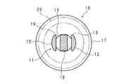
図13は、本体部11の横断面図であり、図12中のA−A線による断面が示されている。本図に示すように内軸18は、矩形の横断面形状を有している。外筒19は、内軸18の外側を間隙を隔てて囲う円筒体の一部を構成する部分円筒であり、軸対称となる位置に一対設けてある。外筒19の内面は、互いに平行をなす平坦面としてあり、内軸18の相対向する2面の夫々と間隙を隔てて対向している。
FIG. 13 is a cross-sectional view of the
図12に示すように外筒19は、軸長方向の中央部を最大径とし、両端部に向けて連続的に縮径する樽形の軸断面形状を有しており、外筒19の外周面には、実施の形態1と同様の雄ねじ部12が設けられている。
As shown in FIG. 12, the
以上の構成を有する実施の形態4の穴埋め具1は、実施の形態1と同様、ABS樹脂、ポリ塩化ビニル樹脂等の弾性に富む樹脂材料により形成される。外筒19の内面は、前述の如く、平行をなして対向する平坦面としてあるから、穴埋め具1は、外筒19の内面に沿う方向に2つ割りされる成形型を用い、外筒19の外周の雄ねじ部12を含めて一体成形することができる。
The
本体部11の外筒19は、内向きの力を加えることにより、内軸18に連なる先端部を支えとし、内軸18との間の間隙を狭める向きに弾性的に撓み変形する。この変形により外筒19の外径、即ち、本体部11の外径が小さくなる。本体部11の頭部10は、薄肉の張り出し部17を有しており、この張り出し部17は、周縁に厚さ方向の力を加えることにより撓み変形する。
By applying an inward force, the
実施の形態4の穴埋め具1による穴埋めは、実施の形態1と同様、外壁Wに設けた足場固定用の固定穴Hに本体部11の先端を整合させ、ハンマー等の工具又は手により、図中の白抜き矢印に示す方向の押し込み力を頭部10に加える手順で実施される。図14は、実施の形態4に係る穴埋め具1により固定穴Hを埋めた状態を示す模式図である。なお本図においては、固定穴Hに埋設されたグリップアンカー2及び外筒19の外周に形成された雄ねじ部12の図示を省略している。
Filling with the
本体部11の外筒19は、固定穴Hの内面から加わる力の作用により前述の如く撓み、本体部11は外径を小さくするように変形しつつ固定穴Hに押し込まれ、固定穴Hは、図14に示すように穴埋めされる。外筒19は、穴埋め完了後に弾性復帰し、固定穴Hの内面、より詳しくはグリップアンカー2の内面に押し付けられる。これにより、実施の形態1と同様、外筒19外周の雄ねじ部12がグリップアンカー2の内周に設けた雌ねじ部22に係合するから、穴埋め状態を維持することができる。
The
穴埋め具1に固定穴Hから引き抜く向きの力が加えられた場合、外筒19は、内軸18に連なる先端部を支えとして内軸18との間の間隙を拡げる向きに撓み変形し、固定穴Hの内面に強く押し付けられる。従って、実施の形態4の穴埋め具1は、図14に示す穴埋め状態を強固に維持することができる。
When a force in a direction of pulling out from the fixing hole H is applied to the
穴埋め具1の頭部10は、固定穴Hよりも大径の張り出し部17を備えており、この張り出し部17は、図14に示す穴埋め状態において、固定穴Hの開口部周辺の壁面に当接し、固定穴Hは、張り出し部17を備える大径の頭部10により開口部が覆われた状態で穴埋めされる。張り出し部17は、厚さ方向の撓み変形が可能であり、穴埋め具1の押し込みにより図14に示す如く変形し、固定穴H周辺の壁面に弾性的に密着する。従って、固定穴Hの内部への雨水の浸入を防止し、グリップアンカー2の発錆等の固定穴Hの損傷を抑制することができる。頭部10は、楕円形、多角形等の円形以外の形状としてもよいが、円形である場合、押し込みによる変形程度が全周に亘って均等となり、雨水の浸入を有効に防止することができる。
The
雨水の浸入をより確実に防止するために、図12、図13中に2点鎖線により示すシール部材20を用いることができる。図示のシール部材20は、環状の板パッキンであり、本体部11に連なる頭部10の一面に張り出し部17の周縁近くを囲うように周設されている。このように設けられたシール部材20は、図14に示す穴埋め状態において、固定穴Hの開口部周辺の壁面に弾接して封止機能を果たす。シール部材20は、頭部10に連なる本体部11の基部に巻着され、固定穴Hの内面に弾接してシール作用をなすOリングであってもよい。なお大径の頭部10及びシール部材20は、実施の形態1、2、3においても適用可能であり、固定穴Hの内部への雨水の浸入を防止するという同様の効果が得られる。
In order to more reliably prevent infiltration of rainwater, a
更に、実施の形態4に係る穴埋め具1によれば、壁面に対して非直角に形成された固定穴の穴埋めが可能である。図15は、実施の形態4に係る穴埋め具1により非直角の固定穴を埋めた状態を示す模式図である。
Furthermore, according to the
図に示す固定穴Hは、外壁Wの壁面に対して非直角に形成されている。実施の形態4の穴埋め具1において、本体部11の一対の外筒19が樽型の軸断面形状を有しており、夫々の外筒19を軸長方向の異なる位置で固定穴Hの内面に当て、図示の如く、本体部11の軸心線Xを固定穴Hの中心線Yに対して傾けて押し込むことができる。この押し込みにより、穴埋め具1は、一方(図における下方)の外筒19を他方(図における上方)の外筒19よりも大きく撓み変形させて傾きを保ち、固定穴Hは、開口部周辺に頭部10が密着した図14と同等の形態で穴埋めされる。
The fixing hole H shown in the figure is formed at a right angle to the wall surface of the outer wall W. In the
今回開示された実施の形態はすべての点で例示であって、制限的なものではないと考えられるべきである。本開示の範囲は、上記した意味ではなく、特許請求の範囲によって示され、特許請求の範囲と均等の意味及び範囲内でのすべての変更が含まれることが意図される。即ち、請求項に示した範囲で適宜変更した技術的手段を組み合わせて得られる実施形態も本開示の技術的範囲に含まれる。 The embodiment disclosed this time is an example in all respects and should be considered as not being restrictive. The scope of the present disclosure is defined by the terms of the claims, rather than the description above, and is intended to include any modifications within the scope and meaning equivalent to the terms of the claims. That is, embodiments obtained by combining technical means appropriately changed within the scope of the claims are also included in the technical scope of the present disclosure.
1 穴埋め具
10 頭部
11 本体部
110 割り溝
12 雄ねじ部
13 小孔(係合部)
14 溝
18 内軸
19 外筒
2 グリップアンカー
22 雌ねじ部
30 塗膜
4 工具
W 外壁
H 固定穴
DESCRIPTION OF
14
Claims (13)
外径が小さくなるように変形する軸状の本体部と、
該本体部の一端部に連なる頭部と
を備える穴埋め具。 A hole filling device for filling a screw hole for fixing a scaffold formed on an outer wall of a building,
A shaft-shaped main body that is deformed so as to have a smaller outer diameter;
A hole filling device comprising: a head connected to one end of the main body.
前記本体部を前記ねじ穴に挿入する
穴埋め方法。 A scaffold formed on an outer wall of a building, the other end of the main body of the hole filling device having a shaft-shaped main body that is deformed so as to have a smaller outer diameter, and a head connected to one end of the main body. Align with the fixing screw holes,
A hole filling method for inserting the main body into the screw hole.
Applications Claiming Priority (2)
| Application Number | Priority Date | Filing Date | Title |
|---|---|---|---|
| JP2018188586 | 2018-10-03 | ||
| JP2018188586 | 2018-10-03 |
Publications (2)
| Publication Number | Publication Date |
|---|---|
| JP2020056294A true JP2020056294A (en) | 2020-04-09 |
| JP6967793B2 JP6967793B2 (en) | 2021-11-17 |
Family
ID=70106908
Family Applications (1)
| Application Number | Title | Priority Date | Filing Date |
|---|---|---|---|
| JP2019151417A Active JP6967793B2 (en) | 2018-10-03 | 2019-08-21 | Filling tools and filling methods |
Country Status (1)
| Country | Link |
|---|---|
| JP (1) | JP6967793B2 (en) |
Cited By (1)
| Publication number | Priority date | Publication date | Assignee | Title |
|---|---|---|---|---|
| USD1123600S1 (en) | 2021-11-19 | 2026-04-28 | Nichiha Corporation | Member for closing a hole in a building board |
Citations (10)
| Publication number | Priority date | Publication date | Assignee | Title |
|---|---|---|---|---|
| JPS4823861U (en) * | 1971-07-28 | 1973-03-19 | ||
| JPS53155217U (en) * | 1977-05-13 | 1978-12-06 | ||
| JPS55115807U (en) * | 1979-02-06 | 1980-08-15 | ||
| JPS585792Y2 (en) * | 1977-10-25 | 1983-02-01 | 岡部株式会社 | Cap for concrete embedded screw joint tube |
| JPH0431951U (en) * | 1990-07-10 | 1992-03-16 | ||
| JP3055917U (en) * | 1998-07-16 | 1999-02-02 | タキゲン製造株式会社 | Bolt hole concealment cap |
| JP3055940U (en) * | 1998-07-17 | 1999-02-02 | タキゲン製造株式会社 | Bolt hole concealment cap |
| JP2007009561A (en) * | 2005-06-30 | 2007-01-18 | Toho Kinzoku Kogyo Kk | Perforated mask cap, wall surface repair device and wall surface repair method |
| JP2009024340A (en) * | 2007-07-17 | 2009-02-05 | Airtech Japan:Kk | Scaffolding bracket protection member |
| JP3148706U (en) * | 2008-12-10 | 2009-02-26 | 東邦金属工業株式会社 | Masking cap for scaffolding |
-
2019
- 2019-08-21 JP JP2019151417A patent/JP6967793B2/en active Active
Patent Citations (10)
| Publication number | Priority date | Publication date | Assignee | Title |
|---|---|---|---|---|
| JPS4823861U (en) * | 1971-07-28 | 1973-03-19 | ||
| JPS53155217U (en) * | 1977-05-13 | 1978-12-06 | ||
| JPS585792Y2 (en) * | 1977-10-25 | 1983-02-01 | 岡部株式会社 | Cap for concrete embedded screw joint tube |
| JPS55115807U (en) * | 1979-02-06 | 1980-08-15 | ||
| JPH0431951U (en) * | 1990-07-10 | 1992-03-16 | ||
| JP3055917U (en) * | 1998-07-16 | 1999-02-02 | タキゲン製造株式会社 | Bolt hole concealment cap |
| JP3055940U (en) * | 1998-07-17 | 1999-02-02 | タキゲン製造株式会社 | Bolt hole concealment cap |
| JP2007009561A (en) * | 2005-06-30 | 2007-01-18 | Toho Kinzoku Kogyo Kk | Perforated mask cap, wall surface repair device and wall surface repair method |
| JP2009024340A (en) * | 2007-07-17 | 2009-02-05 | Airtech Japan:Kk | Scaffolding bracket protection member |
| JP3148706U (en) * | 2008-12-10 | 2009-02-26 | 東邦金属工業株式会社 | Masking cap for scaffolding |
Cited By (1)
| Publication number | Priority date | Publication date | Assignee | Title |
|---|---|---|---|---|
| USD1123600S1 (en) | 2021-11-19 | 2026-04-28 | Nichiha Corporation | Member for closing a hole in a building board |
Also Published As
| Publication number | Publication date |
|---|---|
| JP6967793B2 (en) | 2021-11-17 |
Similar Documents
| Publication | Publication Date | Title |
|---|---|---|
| US8640716B2 (en) | Cosmetic applicator | |
| JP3220888U (en) | Washer built-in screw | |
| WO2005121570A1 (en) | Falling-off prevention device and loosening prevention nut | |
| US11384866B2 (en) | Pipe clamp | |
| TWI754685B (en) | Piston tight fitting fixture | |
| JP5262276B2 (en) | How to repair cracks in concrete structures | |
| JP6967793B2 (en) | Filling tools and filling methods | |
| GB2240828A (en) | Installation of a fastener in a support | |
| JP2012504214A (en) | Fastening device | |
| JP2017177247A (en) | Oil seal installation tool | |
| JP2004245419A (en) | Grommet | |
| JP3219727U (en) | Repair pin for outer wall tile pilot hole | |
| JPH10235662A (en) | Insert fixing jig for rotational molding die | |
| JP3232830U (en) | Screws with a tightened display function | |
| JPH0989179A (en) | Piping joint | |
| JP2922891B1 (en) | Anchor holder for concrete product molding | |
| JP3798262B2 (en) | Joints such as segments | |
| JP3084236B2 (en) | Formwork apparatus for manufacturing concrete tubular block having mounting holes for step mounting | |
| JPH116506A (en) | Telescopic pipe | |
| JPH0641013Y2 (en) | Fixing device for piston in fluid cylinder | |
| JPH0353047Y2 (en) | ||
| JP6667883B1 (en) | Formwork auxiliary tool | |
| JPH1015840A (en) | Bolt tightening jig | |
| JPH03239805A (en) | Self-expanding fixing bolt | |
| JP2024012111A (en) | Fastening member holding device |
Legal Events
| Date | Code | Title | Description |
|---|---|---|---|
| A621 | Written request for application examination |
Free format text: JAPANESE INTERMEDIATE CODE: A621 Effective date: 20190821 |
|
| A521 | Request for written amendment filed |
Free format text: JAPANESE INTERMEDIATE CODE: A523 Effective date: 20190829 |
|
| AA64 | Notification of invalidation of claim of internal priority (with term) |
Free format text: JAPANESE INTERMEDIATE CODE: A241764 Effective date: 20191001 |
|
| A131 | Notification of reasons for refusal |
Free format text: JAPANESE INTERMEDIATE CODE: A131 Effective date: 20200901 |
|
| A521 | Request for written amendment filed |
Free format text: JAPANESE INTERMEDIATE CODE: A523 Effective date: 20201019 |
|
| A131 | Notification of reasons for refusal |
Free format text: JAPANESE INTERMEDIATE CODE: A131 Effective date: 20210330 |
|
| A521 | Request for written amendment filed |
Free format text: JAPANESE INTERMEDIATE CODE: A523 Effective date: 20210510 |
|
| TRDD | Decision of grant or rejection written | ||
| A01 | Written decision to grant a patent or to grant a registration (utility model) |
Free format text: JAPANESE INTERMEDIATE CODE: A01 Effective date: 20211012 |
|
| A61 | First payment of annual fees (during grant procedure) |
Free format text: JAPANESE INTERMEDIATE CODE: A61 Effective date: 20211019 |
|
| R150 | Certificate of patent or registration of utility model |
Ref document number: 6967793 Country of ref document: JP Free format text: JAPANESE INTERMEDIATE CODE: R150 |
|
| R250 | Receipt of annual fees |
Free format text: JAPANESE INTERMEDIATE CODE: R250 |