JP2020009977A - Imaging apparatus, imaging method, positioning device, and die bonder - Google Patents
Imaging apparatus, imaging method, positioning device, and die bonder Download PDFInfo
- Publication number
- JP2020009977A JP2020009977A JP2018132015A JP2018132015A JP2020009977A JP 2020009977 A JP2020009977 A JP 2020009977A JP 2018132015 A JP2018132015 A JP 2018132015A JP 2018132015 A JP2018132015 A JP 2018132015A JP 2020009977 A JP2020009977 A JP 2020009977A
- Authority
- JP
- Japan
- Prior art keywords
- imaging
- camera
- area
- line
- image
- Prior art date
- Legal status (The legal status is an assumption and is not a legal conclusion. Google has not performed a legal analysis and makes no representation as to the accuracy of the status listed.)
- Granted
Links
Images


Abstract
Description
本発明は、撮像装置、撮像方法、位置決め装置、及びダイボンダに関する。 The present invention relates to an imaging device, an imaging method, a positioning device, and a die bonder.
半導体装置の製造においては、多数個の素子を一括して造り込まれたウェハをダイシングして個々の半導体チップに分離し、これを一個ずつリードフレーム等の所定位置にボンディングするというチップボンディングの手法が採用されている。そして、このチップボンディングにはダイボンダ(ボンディング装置)(例えば、特許文献1)が用いられる。 In the manufacture of semiconductor devices, a chip bonding method in which a wafer in which a large number of elements are manufactured together is diced and separated into individual semiconductor chips, which are bonded one by one to predetermined positions such as a lead frame. Has been adopted. A die bonder (bonding device) (for example, Patent Document 1) is used for this chip bonding.
ダイボンダは、図11に示すように、ウェハ1(図12参照)から切り出されるチップ2をピックアップポジションPにてピップアップして、リードフレームなどの基板3のボンディングポジションQに移送(搭載)するものである。ウェハ1は、ダイシング工程によって、多数のチップ2に分断(分割)される。このため、このチップ2は図12に示すようにマトリックス状に配列される。
As shown in FIG. 11, the die bonder picks up a
このダイボンダは、図11に示すように、コレット(吸着コレット)4を備える。このコレット4は、図示省略の移動機構にて、ピックアップポジションP上での矢印A方向の上昇および矢印B方向の下降と、ボンディングポジションQ上での矢印C方向の上昇および矢印D方向の下降と、ピックアップポジションPとボンディングポジションQとの間の矢印E、F方向の往復動とが可能とされる。移動機構は、例えばマイクロコンピュータ等にて構成される制御手段にて前記矢印A、B、C、D、E、Fの移動が制御される。なお、移動機構としては、シリンダ機構、ボールねじ機構、リニアモータ機構等の種々の機構にて構成することができる。
This die bonder includes a collet (adsorption collet) 4 as shown in FIG. The
吸着コレット4はその下面に開口する吸着孔5を有するヘッド6を備え、吸着孔5を介してチップ2が真空吸引され、このヘッド6の下端面(先端面)にチップ2が吸着する。この真空吸引(真空引き)が解除されれば、ヘッド6からチップ2が外れる。
The
また、多数のチップ2に分断(分割)されたウェハ1は、例えばXYθテーブル8(図12参照)上に配置され、このXYθテーブル8には突き上げピンを備えた突き上げ手段が配置される。すなわち、突き上げ手段によって、ピックアップしようとするチップ2を下方から突き上げ、粘着シートから剥離しやすくする。この状態で、下降してきた吸着コレット4にこのチップ2が吸着する。
The wafer 1 divided (divided) into a large number of
すなわち、コレット4をこのピックアップすべきチップの上方に位置させた後、矢印Bのようにコレット4を下降させてこのチップ2をピックアップする。その後、矢印Aのようにコレット4を上昇させる。
That is, after the
次に、コレット4を矢印E方向へ移動させて、このアイランド部の上方に位置させた後、コレット4を矢印Dのように下降移動させて、このアイランド部にチップ2を供給する。また、アイランド部にチップ2を供給した後は、コレットを矢印Cのように上昇させた後、矢印Fのように、ピップアップ位置の上方の待機位置に戻す。
Next, the
すなわち、コレット4を、順次、矢印A、E、D、C、F、Bのように移動させることによって、ピックアップ位置でチップをコレット4でピックアップし、このチップ2をボンディング位置でチップ2に実装することになる。
That is, the chip is picked up by the
このように、ピックアップ位置においては、ピックアップすべきチップ2の位置確認(位置検出)を行い、ボンディング位置においても、ボンディングすべきリードフレームのアイランド部の位置確認(位置検出)を行う必要がある。このため、一般には、ピックアップ位置の上方位置に配設された確認用カメラにてピックアップすべきチップ2を観察し、コレット4をこのピックアップすべきチップ2の上方に位置させ、また、ボンディング位置の上方位置に配設された確認用カメラにてリードフレームのアイランド部を観察し、コレット4をこのアイランドの上方に位置させる。
As described above, it is necessary to confirm the position of the
このため、このダイボンダでは、ピックアップ位置及びボンディング位置には、確認用カメラ等で構成される位置決め装置が配置される。図10は、ボンディング位置での従来の位置決め方法を示している。この場合、ボンディング位置に搬送されてきた基板(リードフレーム)3に形成されたアイランド部10の位置を確認するものである。図10において、矢印Yは基板3の搬送方向を示し、矢印Xは確認用カメラ11の移動方向を示している。
For this reason, in this die bonder, a positioning device including a confirmation camera or the like is arranged at the pickup position and the bonding position. FIG. 10 shows a conventional positioning method at a bonding position. In this case, the position of the
確認用カメラ11として、エリアセンサカメラを用いている。ここで、エリアセンサカメラとは、撮像素子が縦横方向に並び、図10に示すように、二次元的に画像の撮影ができるカメラである。図10において、Hはこのカメラ11の視野を示している。カメラには、このエリアセンサカメラ以外にラインセンサカメラがある。ラインセンサカメラは、撮像素子が一列に並んでいるものであるので、副走査を伴わない場合、一次元的な画像の撮影しかできない。
As the
このように確認用カメラ11としてエリアセンサカメラを用いている場合、カメラ11の視野Hと、位置決め対象(この場合、基板のアイランド部10)とサイズが同等であれば、カメラ11の視野Hに位置決め対象(アイランド部10)が入るように、順次、移動と停止を繰り返すことになる。このように、確認用カメラ11にて、アイランド部10の位置確認でき、チップ2をボンディングする際、各アイランド部10に正確にボンディングすることができる。
As described above, when the area sensor camera is used as the
しかしながら、カメラ11が移動と停止を繰り返せば、停止時にはカメラ11に振動が生じ、精度の悪い画像を入手することになる。このため、精度の悪い位置決めとなる。また、振動は、しばらくすると停止するので、この停止まで待って画像を入手するようにすれば、精度の良い位置決めを行うことができる。しかしながら、このような振動が停止するまで待つ工程を設ければ、この振動停止待ちのディレイ(遅延)によってスループット(単位時間当たりの処理能力)が悪化する。
However, if the
ところで、カメラ11として、このようなエリアセンサカメラに代えてラインセンサカメラを用い、カメラと物体とを相対移動させることによって、各アイランド部の位置決め画像を取得するようにすることも可能である。
By the way, it is also possible to use a line sensor camera as the
しかしながら、このようなラインセンサカメラを用いると、最初の対象物であるアイランド部全体を撮像する場合にもカメラを移動させる必要がある。このため、初期調整用の画像(照明調整用等の画像)を得る処理時間を必要として、作業効率の劣化を招く。しかも、ラインセンサカメラは、エリアセンサカメラよりも高価である。 However, when such a line sensor camera is used, it is necessary to move the camera even when imaging the entire island portion which is the first object. For this reason, a processing time for obtaining an image for initial adjustment (image for illumination adjustment or the like) is required, resulting in deterioration of work efficiency. Moreover, line sensor cameras are more expensive than area sensor cameras.
本発明は、上記課題に鑑みて、作業効率に優れ、安定して高精度の撮像が可能であり、しかも低コスト化が可能な撮像装置、撮像方法、位置決め装置、及びダイボンダを提供する。 The present invention has been made in view of the above problems, and provides an imaging apparatus, an imaging method, a positioning apparatus, and a die bonder that are excellent in work efficiency, capable of performing stable high-precision imaging, and capable of reducing costs.
本発明の撮像装置は、ワークの複数の撮影部位を撮像する撮像装置であって、ワークにおける少なくとも一つの撮影部位のエリア撮像が可能なカメラと、このカメラとワークとの相対的な移動が可能な移動手段とを備え、前記カメラは、前記移動手段によるカメラとワークとの相対移動中に、撮影部位に対してライン撮像を行うものである。 An imaging apparatus according to the present invention is an imaging apparatus for imaging a plurality of imaging parts of a work, and a camera capable of imaging an area of at least one imaging part of the work, and a relative movement between the camera and the work. The camera performs line imaging on an imaging part during relative movement between the camera and the workpiece by the moving unit.
本発明の撮像装置によれば、ワークの一つの撮影部位をエリア撮像することができ、その後、そのカメラを用いて、各撮影部位のライン撮像を行うことができて、全撮影部位の画像観察を行うことができる。ライン撮像においては、カメラを停止させる必要がなく、カメラの停止による振動を生じさせない。 ADVANTAGE OF THE INVENTION According to the imaging device of this invention, one imaging | photography site | part of a workpiece | work can be area-photographed, after that, the line imaging of each imaging | photography site | part can be performed using the camera, and the image observation of all the imaging | photography sites | parts It can be performed. In line imaging, there is no need to stop the camera, and no vibration is caused by stopping the camera.
移動手段として、ワーク側を移動させるワーク搬送手段として第1移動機構のみ、カメラを移動させる第2移動機構のみ、又は、第1移動機構及び第2移動機構で構成できる。この場合、第1移動機構として、X方向及びこのX方向と直交するY方向にワークを移動させることができ、第2移動機構としてもX方向及びこのX方向と直交するY方向にカメラを移動させることができるものが好ましい。なお、移動手段には、カメラの内部的に行われる電子的な走査も含むものであってもよい。 The moving means may be constituted by only the first moving mechanism as the work conveying means for moving the work side, only the second moving mechanism for moving the camera, or the first moving mechanism and the second moving mechanism. In this case, the first moving mechanism can move the work in the X direction and the Y direction orthogonal to the X direction, and the second moving mechanism also moves the camera in the X direction and the Y direction orthogonal to the X direction. What can be made is preferable. The moving means may include electronic scanning performed inside the camera.
前記カメラによるライン撮像の可能範囲は、一の撮影部位のライン撮像方向の全長と同一乃至全長よりも長いように設定するのが好ましい。このように設定することによって、ライン撮像にて撮影部位の全範囲の撮影を安定して行える。 It is preferable that the possible range of the line imaging by the camera is set to be equal to or longer than the entire length of one imaging region in the line imaging direction. By setting in this way, it is possible to stably shoot the entire range of the imaging region by line imaging.
カメラとワークとの相対的な移動には折り返し動作部があり、この折り返し動作部においては、ライン撮像をそのライン撮像方向を切り換えて行うことができる。このため、折り返し動作部の撮像をライン撮像にて撮影することができる。これによって、カメラとワークとの相対的な移動の軌跡として四角形の渦巻き形状としたり、直角ジグザグ形状としたりできる。このため、ワークの大きさ、ワークに設けられた撮影部位の配置ピッチ、配置数等に応じて、種々の軌跡でもって撮像(撮影)することができる。 The relative movement between the camera and the work includes a return operation unit. In this return operation unit, line imaging can be performed by switching the line imaging direction. For this reason, the imaging of the folding operation unit can be performed by line imaging. Thus, the trajectory of the relative movement between the camera and the work can be a rectangular spiral shape or a right-angle zigzag shape. For this reason, it is possible to take an image (photograph) along various trajectories according to the size of the work, the arrangement pitch of the imaging parts provided on the work, the number of arrangements, and the like.
また、折り返し動作部においては、ライン撮像方向の切り換えを行わないでエリア撮像を行うものであってもよい。この場合、折り返し部において、ライン撮像方向を切り換える必要がないので、作業の簡略化を図ることができる。 Further, the return operation unit may perform area imaging without switching the line imaging direction. In this case, since it is not necessary to switch the line imaging direction in the turnback unit, the operation can be simplified.
画像処理動作前において、エリア撮像又はライン撮像された画像に対してレシピ調整を行うレシピ調整手段を備え、このレシピ調整手段に調整したレシピで、レシピ調整手段において用いた撮影方法と異なるライン撮像又はエリア撮像された画像を用いて画像処理動作を行うものであってもよい。ここで、レシピ調整とは、撮像パラメータ(露光時間、カメラゲイン、照明発光条件、レンズのフォーカス・絞り)や画像処理パラメータ(位置決め、検査のしきい値等)を調整することであり、所定の画像処理を行うめの調整である。 Before the image processing operation, the image processing apparatus further includes a recipe adjustment unit that performs a recipe adjustment on the image captured by the area imaging or the line imaging. An image processing operation may be performed using an image captured in an area. Here, the recipe adjustment is to adjust imaging parameters (exposure time, camera gain, illumination light emission condition, lens focus / aperture) and image processing parameters (positioning, inspection threshold, and the like). This is an adjustment for performing image processing.
このように、位置決めや検査処理を行う前工程において、エリア撮像された画像に対してレシピ調整を行い、このレシピを用いてライン撮像してその画像にて、位置決めや検査処理を行ったり、ライン撮像された画像に対してレシピ調整を行い、このレシピを用いてエリア撮像してその画像にて、位置決めや検査処理を行ったりでき、作業性の向上を図ることができる。例えば、位置決めや検査処理を、エリア撮像された画像に対してレシピ調整を行い、このレシピを用いてライン撮像する場合、ライブ表示を行いながら、撮像パラメータや画像処理パラメータを調整することができ、これによって、パラメータ変更のフィードバックを得ることができ、最適条件でライン撮像することができる。なお、ライン撮像された画像に対してレシピ調整を行い、このレシピを用いてエリア撮像する場合においても、連続して走査することによって、不連続ながらライブ表示が可能である。 As described above, in the pre-process of performing the positioning and inspection processing, the recipe is adjusted for the image captured in the area, the line is captured using the recipe, and the positioning and inspection processing is performed on the image. Recipe adjustment is performed on the captured image, an area is captured using this recipe, positioning and inspection processing can be performed on the image, and workability can be improved. For example, for positioning and inspection processing, a recipe adjustment is performed on an image captured in an area, and when line imaging is performed using this recipe, imaging parameters and image processing parameters can be adjusted while performing live display, As a result, feedback of parameter change can be obtained, and line imaging can be performed under optimal conditions. It should be noted that, even when recipe adjustment is performed on an image obtained by line imaging and area imaging is performed using this recipe, live display can be performed discontinuously by continuously scanning.
また、エリア撮像された画像を用いて仮調整したレシピをライン撮像に適用し、仮調整したレシピを登録し、及び/又は、ライン撮像に適用した結果をユーザが評価して、その評価に基づいて一部修正したレシピを登録することができる。ここで、仮調整とは、位置決めや検査処理時の実際の撮影時の撮影方法とは異なる撮影方法(この場合、ライン撮像)でレシピ調整を行うことである。このように構成することによって、ユーザが(強制的に)確認することができ、安定した高精度の画像を得ることができる。 In addition, the recipe temporarily adjusted using the image captured in the area is applied to the line imaging, the temporarily adjusted recipe is registered, and / or the user evaluates the result applied to the line imaging, and based on the evaluation, To register a partially modified recipe. Here, the tentative adjustment is to perform a recipe adjustment using an imaging method (in this case, line imaging) different from the imaging method at the time of actual imaging during positioning or inspection processing. With such a configuration, the user can (forcedly) check the image and obtain a stable high-precision image.
エリア撮像又はライン撮像で撮影した画像に対してレシピ調整を行うレシピ調整手段を備え、このレシピ調整手段は、エリア撮像とライン撮像との切替を行う切替手段を備えるように構成できる。エリア撮像にて得られたエリア画像とライン撮像にて得られたライン画像では照明の配光の差、レンズの収差等の影響によって全く同一の画像にならない。また、これらの影響はワークによって変化する。レシピ調整を行う際に、利便性を考えるとエリア撮像された画像を用いて調整を行うことになる。しかしながら、実際のライン画像(ライン撮像にて得られたライン画像)とは異なるため、ある程度調整した後、ライン画像に切り替えて確認する必要があり、このように、エリア撮像とライン撮像との切替を行う切替手段を備えることによって、この対応が可能となる。また、切替手段を備えていれば、レシピ調整を行う前に、2つの画像(エリア画像とライン画像)が大きく相違しないことを確認できる利点もある。 The image processing apparatus may include a recipe adjustment unit that performs recipe adjustment on an image captured by area imaging or line imaging. The recipe adjustment unit may include a switching unit that switches between area imaging and line imaging. The area image obtained by the area imaging and the line image obtained by the line imaging do not become completely the same image due to a difference in illumination light distribution, an aberration of a lens, and the like. Further, these effects vary depending on the workpiece. When the recipe adjustment is performed, the adjustment is performed using the area imaged image in consideration of convenience. However, since it is different from the actual line image (the line image obtained by the line imaging), it is necessary to make some adjustments and then switch to the line image for confirmation, and thus switch between the area imaging and the line imaging. This is made possible by providing the switching means for performing the above. Further, if the switching means is provided, there is an advantage that it is possible to confirm that the two images (the area image and the line image) do not greatly differ before performing the recipe adjustment.
ライン撮像時にエラーが発生した際に、このエラーが発生した撮影部位に対してエリア撮像を行うのが好ましい。この場合、カメラがこのエラーが発生した部位から離間した位置に移動していても、カメラをそのエラーが発生した部位に戻してエリア撮像することができ、エラー発生時のユーザの利便性を向上させることができる。すなわち、エリア撮像を用いることによって、エラーが発生した部位での、ライブ表示をカメラの走査なしで行える利点がある。 When an error occurs during line imaging, it is preferable to perform area imaging on the imaging site where the error has occurred. In this case, even if the camera is moved to a position away from the site where the error has occurred, the camera can be returned to the site where the error has occurred and the area can be imaged, thereby improving the convenience of the user when the error occurs. Can be done. In other words, there is an advantage that live display can be performed without scanning by a camera at a site where an error has occurred by using area imaging.
本発明の位置決め装置は、搬送されてきた基板上の撮影部位である複数個の被検査部位の画像観察を行って各被検査部位の位置決めを行う位置決め装置であって、被検査部位の画像観察に前記撮像装置を用いるものである。 The positioning device of the present invention is a positioning device that performs image observation of a plurality of inspected sites, which are imaging sites on a substrate that has been transported, and positions each of the inspected sites. The above-mentioned image pickup device is used.
本発明の位置決め装置によれば、照明調整用等の初期調整用の画像を、基板搬送後及び撮像パラメータ変更後に得ることができ、作業時間の短縮を図ることができる。カメラの停止による振動を生じさせないので、高精度の位置合わせが可能となる。しかも、カメラが振動しないので、振動が収まるまで、撮像するのを停止する必要がなく、作業効率のよい位置合わせを行うことができる。また、ラインセンサカメラを用いないので、装置の低コスト化を図ることができる。 ADVANTAGE OF THE INVENTION According to the positioning device of this invention, the image for initial adjustments, such as for illumination adjustment, can be obtained after board | substrate conveyance and an imaging parameter change, and can shorten work time. Since no vibration is caused by stopping the camera, highly accurate positioning can be performed. In addition, since the camera does not vibrate, there is no need to stop imaging until the vibration stops, and positioning with high working efficiency can be performed. Further, since a line sensor camera is not used, the cost of the apparatus can be reduced.
本発明のダイボンダは、ピックアップポジションにてチップをピックアップし、このピックアップしたチップをボンディングポジョンに搬送して、そのボンディングポジションにてチップをボンディングするダイボンダであって、いずれか任意の位置で前記位置決め装置を用いた位置決めを可能としたものである。 A die bonder of the present invention is a die bonder that picks up a chip at a pickup position, transports the picked up chip to a bonding position, and bonds the chip at the bonding position, wherein the positioning device is located at any arbitrary position. This makes it possible to perform positioning by using.
本発明のダイボンダによれば、照明調整用等の初期調整用の画像を、ワーク搬送後直ちに得ることができる。その後、このカメラを用いて、各撮影部位のライン撮像を行うことができ、全撮影部位の撮影・観察や位置決めを行うことができる。このライン撮像においては、カメラを停止又は減速させる必要がなく、カメラに停止又は減速による振動を生じさせない。ライン撮像のタイミングは、移動軸の位置信号に同期することで正しい縦横比で撮影できる(画像を取得できる)。また、移動速度がおよそ一定になるように制御することによって、一定間隔で撮像してもよい。 ADVANTAGE OF THE INVENTION According to the die bonder of this invention, the image for initial adjustments, such as for illumination adjustment, can be obtained immediately after a workpiece | work conveyance. Thereafter, line imaging of each imaging region can be performed using this camera, and imaging, observation, and positioning of all imaging regions can be performed. In this line imaging, there is no need to stop or decelerate the camera, and no vibration is caused by the stop or deceleration of the camera. By synchronizing the timing of line imaging with the position signal of the moving axis, it is possible to capture an image with a correct aspect ratio (an image can be acquired). In addition, by controlling the moving speed to be approximately constant, images may be taken at regular intervals.
本発明の一の撮像方法は、ワークの複数の撮影部位を撮像する撮像方法であって、ワークにおける少なくとも一つの撮影部位のエリア撮像を行うエリア撮像工程と、エリア撮像工程終了後、エリア撮像したエリアセンサカメラにて各撮影部位に対してライン撮像を行うライン撮像工程とを備えたものである。 One imaging method of the present invention is an imaging method for imaging a plurality of imaging parts of a work, and an area imaging step of imaging an area of at least one imaging part of the work, and after the area imaging step, area imaging is performed. A line imaging step of performing a line imaging for each imaging region by the area sensor camera.
また、他の撮像方法は、ワークの複数の撮影部位を撮像する撮像方法であって、エリア撮像が可能なカメラを用い、カメラとワークとが相対的に移動し、この移動には、折り返し動作部があり、この折り返し動作部においては、前記カメラのライン撮像方向の切り換えを行うものである。 Another imaging method is an imaging method for imaging a plurality of imaging parts of a work. The camera and the work relatively move using a camera capable of area imaging. The folding operation section switches the line imaging direction of the camera.
本発明では、カメラに停止による振動を生じさせないので、高精度の画像の撮像が可能となる。しかも、カメラが振動しないので、振動が収まるまで、撮像するのを停止する必要がなく、作業効率のよい画像の撮像を行うことができる。また、ラインセンサカメラを用いないので、装置の低コスト化を図ることができる。 According to the present invention, since the camera is not caused to vibrate by stopping, it is possible to capture an image with high accuracy. In addition, since the camera does not vibrate, it is not necessary to stop imaging until the vibration stops, and an image with high working efficiency can be obtained. Further, since a line sensor camera is not used, the cost of the apparatus can be reduced.
以下本発明の実施の形態を図1〜図9に基づいて説明する。図9は、本発明に係るダイボンダ(ボンディング装置:半導体装置の製造装置)を示す。このようなボンディング装置は、ウェハから切り出されるチップ(半導体チップ)21をピックアップポジションPにてコレット(吸着コレット)23でピックアップして、リードフレームなどの基板22のボンディングポジションQに移送(搭載)するものである。ウェハは、金属製のリング(ウェハリング)に張設されたウェハシート24上に粘着されており、ダイシング工程によって、多数のチップ21に分断(分割)される。
Hereinafter, embodiments of the present invention will be described with reference to FIGS. FIG. 9 shows a die bonder (bonding apparatus: semiconductor device manufacturing apparatus) according to the present invention. Such a bonding apparatus picks up a chip (semiconductor chip) 21 cut out from a wafer at a pickup position P with a collet (adsorption collet) 23 and transfers (mounts) it to a bonding position Q of a
このダイボンダのコレット23は、図示省略のボンディングアームに支持され、このボンディングアームは、移動機構(移動手段25)(図2参照)にて駆動されることによって、コレット23は、ピックアップポジションP上での矢印A方向の上昇および矢印B方向の下降と、ボンディングポジションQ上での矢印C方向の上昇および矢印D方向の下降と、ピックアップポジションPとボンディングポジションQとの間の矢印E、F方向の往復動とが可能とされる。移動機構(移動手段)25は制御手段26(図2参照)にて前記矢印A、B、C、D、E、Fの移動が制御される。なお、移動機構25としては、シリンダ機構、ボールねじ機構、リニアモータ機構等の種々の機構にて構成することができる。制御手段26は、例えば、CPU(Central Processing Unit)を中心としてROM(Read Only Memory)やRAM(Random Access Memory)等がバスを介して相互に接続されたマイクロコンピュータである。なお、ROMには、CPUが実行するプログラムやデータが格納されている。
The
コレット23には、下面である吸着面23aに開口する吸着孔(図示省略)が形成され、この吸着孔には、真空発生器(図示省略)が接続されている。このため、コレット23の吸着面23aをチップ21と接触状態として、真空発生器を駆動すれば、吸着孔のエアが吸引され、この吸着面23aにチップ21を吸着することができる。なお、真空発生器としては、真空ポンプを使用した真空発生装置であっても、ノズルとディフューザと呼ばれる基本パーツで構成されるエジェクタ式の真空発生装置であってもよい。
The
次に、このダイボンダの動作を説明する。まず、コレット23をこのピックアップすべきチップの上方に位置させた後、矢印Bのようにコレット23を下降させてこのチップ21をピックアップする。その後、矢印Aのようにコレット23を上昇させる。
Next, the operation of this die bonder will be described. First, after the
次に、コレット23を矢印E方向へ移動させて、この基板22のアイランド部の上方に位置させた後、コレット23を矢印Dのように下降移動させて、このアイランド部にチップ21を供給する。また、アイランド部にチップ21を供給した後は、コレットを矢印Cのように上昇させた後、矢印Fのように、ピップアップ位置の上方の待機位置に戻す。
Next, the
すなわち、コレット4を、順次、矢印A、E、D、C、F、Bのように移動させることによって、ピックアップ位置でチップをコレット23でピックアップし、このチップ2をボンディング位置でチップ21に実装することになる。ところで、ボンディング位置には、基板22が供給されることになるが、この場合、基板22は搬送手段として後述する第1移動機構27(図2参照)にて搬送される。搬送手段(第1移動機構)27として、シリンダ機構、ボールねじ機構、リニアモータ機構等の種々の機構にて構成することができる。
That is, by moving the
このように、ピックアップ位置においては、ピックアップすべきチップ21の位置確認(位置検出)を行い、ボンディング位置においても、ボンディングすべきリードフレームのアイランド部の位置確認(位置検出)を行う必要がある。このため、一般には、ピックアップ位置の上方位置に配設された確認用カメラにてピックアップすべきチップ2を観察し、コレット23をこのピックアップすべきチップ21の上方に位置させ、また、ボンディング位置の上方位置に配設された確認用カメラにてリードフレーム22のアイランド部を観察し、コレット23をこのアイランド部の上方に位置させる。
As described above, it is necessary to confirm the position of the
このため、このダイボンダでは、ピックアップ位置及びボンディング位置には、確認用カメラ等で構成される撮像装置が配置される。本発明では、ボンディング位置に搬送されてきたワーク22としての基板(リードフレーム)に形成されたアイランド部30の位置を確認することが可能な撮像装置を備える。
For this reason, in this die bonder, an imaging device including a confirmation camera or the like is arranged at the pickup position and the bonding position. The present invention includes an imaging device capable of confirming the position of the
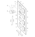
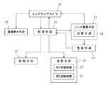
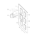
本発明に係る撮像装置は、図2に示すように、搬送されてきた基板における最初の被検査部位である撮影部位をエリア撮像する前記カメラ(エリアセンサカメラ)28と、カメラ28を移動させる第2移動機構29と、前記第1移動機構27を備える。このため、第1移動機構27と第2移動機構29とで、カメラ28とワーク22(基板)とを相対的に直交する2軸方向に移動させる移動手段31を構成できる。なお、移動手段には、カメラの内部的に行われる電子的な走査も含む。また、カメラ28は、移動手段31によるカメラ28とワーク22との相対的な移動(搬送)中に、各撮影部位(アイランド部30)に対してライン撮像を行う。
As shown in FIG. 2, the imaging apparatus according to the present invention includes the camera (area sensor camera) 28 that captures an area of an imaging part, which is the first part to be inspected, on the substrate that has been transported, A second moving
ここで、エリアセンサカメラとは、撮像素子が縦横方向に並び、図1の仮想線で示すように、二次元的に画像の撮影ができるカメラである。図1の仮想線の範囲Hはこのカメラの視野を示している。これに対して、ラインセンサカメラがある。ラインセンサカメラは、撮像素子が横一列に並び、一次的な画像の撮影しかできない。しかし、エリアセンサカメラであるカメラ28は、ライン撮像の取得も可能である。すなわち、カメラ28の撮像素子が縦横方向に並んでいるものであるので、任意の1列(1ライン)の撮像素子を用いるようにすれば、ライン撮像の取得が可能となる。このため、このカメラ28には、エリアセンサカメラとして機能するエリアモードと、ラインセンサカメラとして機能するラインモードとに切り替えが可能となっている。この切り替えは、前記制御手段26にて制御できる。
Here, the area sensor camera is a camera in which image sensors are arranged in the vertical and horizontal directions, and can take a two-dimensional image as shown by the imaginary line in FIG. The range H of the virtual line in FIG. 1 indicates the field of view of the camera. On the other hand, there is a line sensor camera. In the line sensor camera, the imaging devices are arranged in a horizontal line, and can only take a primary image. However, the
この場合、基板としてのワーク22は、第1移動機構27によって、図1に示すY(Y1)方向に搬送され、カメラ28の移動は、第2移動機構29によって、搬送方向Y(Y1)と直交するX(X1,X2)方向に沿って移動する。第2移動機構29は、シリンダ機構、ボールねじ機構、リニアモータ機構等の種々の機構にて構成することができる。ライン撮像のタイミングは、ロータリエンコーダやリニアエンコーダのエンコーダ値又は位置指令値等の位置情報を用いて設定できる。
In this case, the
ところで、この撮像装置には、図2に示すように、レシピ調整手段32と、カメラ28にて撮像した画像を表示する画像表示手段33と、登録手段35とを備える。ここで、レシピ調整とは、撮像パラメータ(露光時間、カメラゲイン、照明発光条件、レンズのフォーカス・絞り)や画像処理パラメータ(位置決め、検査のしきい値等)を調整することであり、所定の画像処理を行うための調整である。このため、レシピ調整手段32とは、このような調整を行うものであって、エリア撮像された画像に対してレシピ調整を行い、このレシピを用いてライン撮像してその画像にて、位置決めや検査処理を行う場合と、ライン撮像された画像に対してレシピ調整を行い、このレシピを用いてエリア撮像してその画像にて、位置決めや検査処理を行う場合とがある。
By the way, as shown in FIG. 2, the imaging apparatus includes a
また、このレシピ調整手段32には、エリア撮像とライン撮像との切替を行う切替手段34を備えるように構成できる。エリア撮像にて得られたエリア画像とライン撮像にて得られたライン画像では照明の配光の差、レンズの収差等の影響によって全く同一の画像にならない。また、これらの影響はワークによって変化する。レシピ調整を行う際に、利便性を考えるとエリア撮像された画像を用いて調整を行うことなる。しかしながら、実際のライン画像(ライン撮像にて得られたライン画像)とは異なるため、ある程度調整した後、ライン画像に切り替えて確認する必要があり、このように、エリア撮像とライン撮像との切替を行う切替手段34を備えることによって、対応可能となる。また、切替手段34を備えていれば、レシピ調整を行う前に、2つの画像(エリア画像とライン画像)が大きく相違しないことを確認できる。
Further, the
この場合、このレシピ調整手段32のレシピ調整およびエリア撮像とライン撮像との切替は制御手段26からの指令で行われる。
In this case, the recipe adjustment by the
画像表示手段33は、エリアセンサカメラ28にて撮像したエリア画像やライン画像を表示するモニタを有するものであり、登録手段35は、レシピ調整手段32にて調整したレシピ等を登録(記憶)するものである。この登録手段35は、記憶装置にて構成でき、HDD(Hard Disc Drive)やDVD(Digital Versatile Disk)ドライブ、CD−R(Compact Disc-Recordable)ドライブ、EEPROM(Electronically Erasable and Programmable Read Only Memory)等からなる。
The
次に、前記のように構成された撮像装置を用いた撮像方法を説明する。この場合、図4に示すように、カメラ28とワーク22との相対的な移動としては、直角ジグザグ形状の軌跡K1を描く場合や、図5に示すように、四角形の渦巻き形状の軌跡K2を描いたりすることになる。
Next, an imaging method using the imaging device configured as described above will be described. In this case, as shown in FIG. 4, the relative movement between the
図4の直角ジグザグ形状の軌跡K1を描く場合を、図6及び図1を用いて説明する。図1に示すように、基板(ワーク)22が、矢印Y(Y1)方向に沿って搬送されて所定位置で静止する。この状態では、カメラ28は、基板22のイのアイランド部30のエリア撮像が可能な位置に配置される。このイのアイランド部30は、搬送方向下流端であって、カメラ移動方向上流端のアイランド部30である。
A case where the right-angle zigzag locus K1 in FIG. 4 is drawn will be described with reference to FIGS. As shown in FIG. 1, the substrate (work) 22 is transported along the direction of the arrow Y (Y1) and stops at a predetermined position. In this state, the
まず、図3に示すように、エリア撮像工程S1を行う。すなわち、カメラ28をエリアモードとして、アイランド部30のエリア撮像を行うことによって、照明調整用等の初期調整用の画像を得る(図6のステップS11)。このエリア撮像の視野範囲Hは、イのアイランド部30の全体よりも大きく、このエリア撮像内にイのアイランド部30のうち画像処理に少なくとも必要なものが入るものである。また、初期調整用の画像として、モデル登録のための画像とすることもできる。すなわち、このエリア画像を位置決めモデルとして登録したり、後述するライン画像による位置決めに対する位置決めモデルとして登録したりすることができる。これらの登録には登録手段35に登録することができる。
First, as shown in FIG. 3, an area imaging step S1 is performed. That is, the
このように、エリア撮像が終了すれば、次にライン撮像工程S2を行う。すなわち、カメラ28をラインセンサカメラモード(図6のステップS12)としてカメラ28を矢印X(X1)方向に移動させていく。すなわち、相対的な移動を開始する(ステップS13).この場合、ライン撮像は、一の被検査部位であるアイランド部30のライン撮像方向の全長で可能である。すなわち、ライン撮像の視野Lの長さを、アイランド部30の基板搬送方向長さよりも長く設定する。これによって、基板22上の基板搬送方向下流端の全アイランド部30を撮像することができる。
Thus, when the area imaging is completed, the line imaging step S2 is performed next. That is, the
このように、撮像されたアイランド部30の位置を確認(位置決め)することができ、この位置に基づいて、制御手段26にて移動機構(移動手段)25を調整して、コレット23により、各アイランド部30に対して、正確にボンディングすることができる。
In this manner, the position of the
そして、折り返し動作部に達したか否かを判断し(ステップS14)、達していれば、この場合、カメラ28が矢印X1方向に移動してきているので、ロのアイランド部30のX1の終点(下流点)に対応する位置に位置している。達していなければ、達するまでカメラ8を矢印X1方向に移動する。
Then, it is determined whether or not it has reached the turn-back operation unit (step S14). If it has been reached, the
ステップS15へ移行して、ライン撮像方向を切り換えて、矢印Y2方向へカメラ27を移動させる。その後、折り返し動作部を終了したか否かを判断する(ステップ16)。すなわち、隣の列のハのアイランド30のライン撮像が終了したか否かを判断する。終了していれば、ステップS17へ移行する。ステップS16で終了していなければ、終了するまで行う。
In step S15, the line imaging direction is switched, and the
ステップS17では、作業を終了するか否かを判断する。終了すると判断した場合は、終了し、終了しないと判断した場合、ステップS18へ移行して、ライン撮像方向を切り換えてカメラを矢印X2方向へ移動させる。その後は、ステップS19へ移行して、最終撮影部位の撮像が終了したか否かを判断する。 In step S17, it is determined whether or not to end the operation. If it is determined that the processing is to be ended, the processing is ended. If it is determined that the processing is not to be ended, the process proceeds to step S18, in which the line imaging direction is switched and the camera is moved in the arrow X2 direction. Thereafter, the process proceeds to step S19, and it is determined whether or not the imaging of the final imaging region has been completed.
ステップS19で終了していれば、作業を終了する。終了していなければ、ステップS14へ移行して、前記した工程を順次行う。これによって、図4の直角ジグザグ形状の軌跡K1を描きながら、ワーク(基板22)のすべてのアイランド30の撮像を行うことができる。
If the operation has been completed in step S19, the operation is completed. If not, the process proceeds to step S14, and the above-described steps are sequentially performed. Thereby, it is possible to image all the
また、図5に示す四角形の渦巻き形状の軌跡K2を描く場合も、前記図6のフローチャート図に従って動作していくことによって、ワーク(基板22)のすべてのアイランド30の撮像を行うことができる。
Also in the case of drawing a rectangular spiral locus K2 shown in FIG. 5, it is possible to image all the
また、カメラ28とワーク22との相対的な移動として、図7に示すものであってもよい。ワーク22側を固定として、カメラ28側を移動させた場合を、図8と図1を用いて説明する。なお、図7において、Hはエリア撮像の視野範囲を示している。
Further, the relative movement between the
この場合、図1に示すように、基板(ワーク)22が、矢印Y(Y1)方向に沿って搬送されて所定位置で静止する。この状態では、カメラ28は、基板22のイのアイランド部30のエリア撮像が可能な位置に配置される。このイのアイランド部30は、搬送方向下流端であって、カメラ移動方向上流端のアイランド部30である。
In this case, as shown in FIG. 1, the substrate (work) 22 is transported along the direction of the arrow Y (Y1) and stops at a predetermined position. In this state, the
まず、図3に示すように、エリア撮像工程S1を行う。すなわち、カメラ28をエリアモードとして、アイランド部30のエリア撮像を行うことによって、照明調整用等の初期調整用の画像を得る(図8のステップS21)。このエリア撮像の視野範囲Hは、イのアイランド部30の全体よりも大きく、このエリア撮像内にイのアイランド部30のうち画像処理に少なくとも必要なものが入るものである。
First, as shown in FIG. 3, an area imaging step S1 is performed. In other words, the
このように、エリア撮像が終了すれば、次にライン撮像工程S2を行う。すなわち、カメラ28をラインセンサカメラモード(図8のステップS22)としてカメラ28を矢印X(X1)方向に移動させていく。すなわち、相対的な移動を開始する(ステップS23),この場合、ライン撮像は、一の被検査部位であるアイランド部30のライン撮像方向の全長で可能である。すなわち、ライン撮像の視野Lの長さを、アイランド部30の基板搬送方向長さよりも長く設定する。これによって、基板22上の基板搬送方向下流端の全アイランド部30を撮像することができる。
Thus, when the area imaging is completed, the line imaging step S2 is performed next. That is, the
一列の最終撮影部位を撮像したか否かを判断する(ステップS24)。すなわち、基板22の基板搬送方向下流端のアイランド部30の撮像が完了すれば、基板22を基板搬送方向Y(Y1)に所定量だけ搬送し、撮像が完了していないアイランド部30を前記と同様の方法で、撮像していくことができる。
It is determined whether or not an image of the last row of imaging parts has been captured (step S24). That is, when imaging of the
その後、ステップS25に移行して、隣に撮影部位(アイランド30)が有るか否かを判断する。隣に撮影部位(アイランド30)が有る場合、ステープS26へ移行する。すなわち、図1のロの撮影部位(アイランド30)から、カメラをY2方向に移動させて、ハの撮影部位対応部位まで移動させる。ステップS25でこの場合、隣に撮影部位(アイランド30)が無ければ、作業を終了する。 After that, the process shifts to step S25 to determine whether or not there is an imaging part (island 30) next to the part. When there is an imaging part (island 30) next to the staple, the process proceeds to the staple S26. That is, the camera is moved in the Y2 direction from the imaging region (island 30) shown in FIG. In this case, if there is no adjacent imaging part (island 30) in step S25, the operation ends.
ハの撮影部位対応部位まで移動すれば、ステップS21へ移行する。これによって、図7に示す軌跡K3でもって、カメラ28とワーク22とが相対的に移動することによって、ワークのすべてのアイランド30の撮像を行うことができる。図7のような動作の場合、折り返し部において、ライン撮像方向を切り換える必要がなく、作業の簡略化を図ることができる。
If it has moved to the site corresponding to the imaging site C, the process proceeds to step S21. As a result, the
画像処理動作前において、レシピ調整手段32にて、エリア撮像又はライン撮像された画像に対してレシピ調整を行うことができる。この場合、このレシピ調整手段32に調整したレシピで、レシピ調整手段32において用いた撮影方法と異なるライン撮像又はエリア撮像された画像を用いて画像処理動作を行うものであってもよい。ここで、レシピ調整とは、撮像パラメータ(露光時間、カメラゲイン、照明発光条件、レンズのフォーカス・絞り)や画像処理パラメータ(位置決め、検査のしきい値等)を調整することであり、所定の画像処理を行うための調整である。
Before the image processing operation, the
このように、位置決めや検査処理を行う前工程において、エリア撮像された画像に対してレシピ調整を行い、このレシピを用いてライン撮像してその画像にて、位置決めや検査処理を行ったり、ライン撮像された画像に対してレシピ調整を行い、このレシピを用いてエリア撮像してその画像にて、位置決めや検査処理を行ったりでき、作業性の向上を図ることができる。例えば、位置決めや検査処理を、エリア撮像された画像に対してレシピ調整を行い、このレシピを用いてライン撮像する場合、ライブ表示を行いながら、撮像パラメータや画像処理パラメータを調整することができ、これによって、パラメータ変更のフィードバックを得ることができ、最適条件でライン撮像することができる。なお、ライン撮像された画像に対してレシピ調整を行い、このレシピを用いてエリア撮像する場合においても、連続して走査することによって、不連続ながらライブ表示が可能である。 As described above, in the pre-process of performing the positioning and inspection processing, the recipe is adjusted for the image captured in the area, the line is captured using the recipe, and the positioning and inspection processing is performed on the image. Recipe adjustment is performed on the captured image, an area is captured using this recipe, positioning and inspection processing can be performed on the image, and workability can be improved. For example, for positioning and inspection processing, a recipe adjustment is performed on an image captured in an area, and when line imaging is performed using this recipe, imaging parameters and image processing parameters can be adjusted while performing live display, As a result, feedback of parameter change can be obtained, and line imaging can be performed under optimal conditions. It should be noted that, even when recipe adjustment is performed on an image obtained by line imaging and area imaging is performed using this recipe, live display can be performed discontinuously by continuously scanning.
また、エリア撮像された画像を用いて仮調整したレシピをライン撮像に適用し、仮調整したレシピを登録することができる。ここで、仮調整とは、位置決めや検査処理時の実際の撮影時の撮影方法とは異なる撮影方法(この場合、ライン撮像)でレシピ調整を行うことである。このように構成することによって、ユーザが(強制的に)確認することができ、安定した高精度の画像を得ることができる。 In addition, a recipe provisionally adjusted using an image captured in an area can be applied to line imaging, and a recipe temporarily adjusted can be registered. Here, the tentative adjustment is to perform a recipe adjustment using an imaging method (in this case, line imaging) different from the imaging method at the time of actual imaging during positioning or inspection processing. With such a configuration, the user can (forcedly) check the image and obtain a stable high-precision image.
レシピ調整手段32は、エリア撮像とライン撮像との切替を行う切替手段34を備えるように構成できる。エリア撮像にて得られたエリア画像とライン撮像にて得られたライン画像では照明の配光の差、レンズの収差等の影響によって全く同一の画像にならない。また、これらの影響はワークによって変化する。レシピ調整を行う際に、利便性を考えるとエリア撮像された画像を用いて調整を行うことになる。しかしながら、実際のライン画像(ライン撮像にて得られたライン画像)とは異なるため、ある程度調整した後、ライン画像に切り替えて確認する必要があり、このように、エリア撮像とライン撮像との切替を行う切替手段34を備えることによって、この対応が可能となる。また、切替手段34を備えていれば、レシピ調整を行う前に、2つの画像(エリア画像とライン画像)が大きく相違しないことを確認できる。
The
ライン撮像時にエラーが発生した際に、このエラーが発生した撮影部位に対してエリア撮像を行うのが好ましい。このように構成することによって、エラーが発生した場合、エラーが発生した部位の画像を確認することができる。この場合、カメラがこのエラーが発生した部位から離間した位置に移動していても、カメラをそのエラーが発生した部位に戻してエリア撮像することができ、エラー発生時のユーザの利便性を向上させることができる。すなわち、エリア撮像を用いることによって、エラーが発生した部位でのライブ表示をカメラの走査なしで行える。 When an error occurs during line imaging, it is preferable to perform area imaging on the imaging site where the error has occurred. With this configuration, when an error occurs, an image of a portion where the error has occurred can be confirmed. In this case, even if the camera is moved to a position away from the site where the error has occurred, the camera can be returned to the site where the error has occurred and the area can be imaged, thereby improving the convenience of the user when the error occurs. Can be done. In other words, by using area imaging, live display at a site where an error has occurred can be performed without scanning by a camera.
本発明の撮像装置では、搬送されてきた基板22における最初の被検査部位(アイランド部30)をエリア撮像することができるので、照明調整用等の初期調整用の画像を、基板搬送後および撮像パラメータ変更後に得ることができ、作業時間の短縮を図ることができる。その後、このカメラ28を用いて、各被検査部位のライン撮像を行うことができ、全被検査部位(全アイランド部30)の位置決めを行うことができる。このライン撮像においては、カメラ28を停止させる必要がなく、カメラ28に停止による振動を生じさせない。このため、高精度の位置合わせが可能となる。しかも、カメラが振動しないので、振動が収まるまで、撮像するのを停止する必要がなく、作業効率のよい位置決めを行うことができる。また、ラインセンサカメラを用いないので、装置の低コスト化を図ることができる。
In the image pickup apparatus of the present invention, since the area to be inspected of the first inspected portion (island portion 30) of the transferred
このため、この撮像装置をダイボンダにおける位置決め装置に用いることができ、このように用いれば、高精度の位置合わせが可能となるので、各アイランド部30に対して、正確にボンディングすることができ、ボンディング作業を高精度に短時間で行うことができる。なお、この位置決め装置にて行う位置決めポジションとしては、ダイボンダの任意の位置に設定できる。 For this reason, this imaging device can be used as a positioning device in a die bonder, and if used in this way, high-precision positioning can be performed. The bonding operation can be performed with high accuracy in a short time. The positioning position performed by the positioning device can be set at any position of the die bonder.
ところで、前記実施形態では、カメラ28を基板搬送方向(Y1方向)と直交する方向(X1方向)に沿って移動させていたが、カメラ28を基板搬送方向(Y1方向)と反対方向(Y2)に移動させるものであってもよい。この場合、ライン撮像方向は、基板搬送方向(Y1方向)と直交する方向(X方向)とし、ライン撮像長さを、アイランド部30のX方向長さよりも長く設定する。また、カメラ28を移動させることなく、基板22を基板搬送方向(Y1方向)に移動させるようにしてもよく、カメラ28を基板搬送方向(Y1方向)と反対方向(Y2)に移動させるとともに基板22を基板搬送方向(Y1方向)に移動させるようにしてもよい。なお、X方向と直交する方向、及びY方向と直交する方向とは、厳密に90度であることに限定されず、例えば、85度〜95度程度の角度をなす方向であってもよい。
By the way, in the embodiment, the
すなわち、カメラ28をX方向(X1方向又はX2方向)に移動可能としたり、カメラをY方向(Y1方向又はY2方向)に移動可能としたり、さらには、Y1方向及びY1方向と反対方向(Y2)に搬送可能としたりでき、カメラ28を停止させて、基板22をY1方向及びY1方向と反対方向(Y2)に搬送したりでき、アイランド部30の配置数や配置ピッチ等に応じて、カメラ28の移動方向や基板22の搬送方向等を種々変更できる。
That is, the
本発明は前記実施形態に限定されることなく種々の変形が可能であって、例えば、ライン撮像する場合、一列の撮像素子を用いたが、2列や3列の撮像素子を用いてもよい。基板22のアイランド部30の数としては、任意であり、図例の6個は説明の簡略化のためのものであり、実際には、6個以上の多数個である。また、カメラ28の移動速度としては、このカメラ28にてライン撮像が可能な速度範囲に設定される。チップ21のボンディング動作後において、チップ21の有無やチップ位置の確認等に用いてもよい。
The present invention can be variously modified without being limited to the above-described embodiment. For example, in the case of performing line imaging, a single row of imaging elements is used, but two or three rows of imaging elements may be used. . The number of the
21 チップ
22 基板
28 カメラ(エリアセンサカメラ)
30 撮影部位(被検査部位)
31 走査手段
32 レシピ調整手段
34 切替手段
P ピックアップポジション
Q ボンディングポジション
S1 エリア撮像工程
S2 ライン撮像工程
21
30 Imaging part (part to be inspected)
31 scanning means 32 recipe adjusting means 34 switching means P pickup position Q bonding position S1 area imaging step S2 line imaging step
Claims (12)
ワークにおける少なくとも一つの撮影部位のエリア撮像が可能なカメラと、
このカメラとワークとの相対的な移動が可能な移動手段とを備え、
前記カメラは、前記移動手段によるカメラとワークとの相対移動中に、撮影部位に対してライン撮像を行うことを特徴とする撮像装置。 An imaging device for imaging a plurality of imaging parts of a work,
A camera capable of imaging an area of at least one imaging part in the work,
A moving means capable of relative movement between the camera and the work,
The imaging apparatus according to claim 1, wherein the camera performs line imaging on an imaging part while the moving means moves the camera and the workpiece relative to each other.
被検査部位の画像観察に請求項1〜請求項8のいずれか1項に記載の撮像装置を用いることを特徴とする位置決め装置。 A positioning device that performs image observation of a plurality of inspected sites, which are imaging sites on the conveyed substrate, and positions each inspected site,
A positioning device, wherein the imaging device according to any one of claims 1 to 8 is used for observing an image of a region to be inspected.
いずれかの任意の位置で前記請求項9に記載の位置決め装置を用いた位置決めを可能としたことを特徴とするダイボンダ。 A die bonder that picks up a chip at a pickup position, transports the picked up chip to a bonding position, and bonds the chip at the bonding position.
A die bonder wherein positioning using any one of the positioning devices according to claim 9 is enabled.
ワークにおける少なくとも一つの撮影部位のエリア撮像を行うエリア撮像工程と、
エリア撮像工程終了後、エリア撮像したエリアセンサカメラにて各撮影部位に対してライン撮像を行うライン撮像工程とを備えたことを特徴とする撮像方法。 An imaging method for imaging a plurality of imaging parts of a work,
Area imaging step of performing area imaging of at least one imaging region in the work,
A line imaging step of, after the area imaging step is completed, performing a line imaging for each imaging region with an area sensor camera that has captured the area.
エリア撮像が可能なカメラを用い、カメラとワークとが相対的に移動し、この移動には、折り返し動作部があり、この折り返し動作部においては、前記カメラのライン撮像方向の切り換えを行うことを特徴とする撮像方法。 An imaging method for imaging a plurality of imaging parts of a work,
Using a camera capable of area imaging, the camera and the work relatively move, and this movement includes a folding operation unit. In this folding operation unit, switching of the line imaging direction of the camera is performed. Characteristic imaging method.
Priority Applications (1)
| Application Number | Priority Date | Filing Date | Title |
|---|---|---|---|
| JP2018132015A JP7139174B2 (en) | 2018-07-12 | 2018-07-12 | IMAGING DEVICE, IMAGING METHOD, POSITIONING DEVICE, AND DIE BONDER |
Applications Claiming Priority (1)
| Application Number | Priority Date | Filing Date | Title |
|---|---|---|---|
| JP2018132015A JP7139174B2 (en) | 2018-07-12 | 2018-07-12 | IMAGING DEVICE, IMAGING METHOD, POSITIONING DEVICE, AND DIE BONDER |
Publications (2)
| Publication Number | Publication Date |
|---|---|
| JP2020009977A true JP2020009977A (en) | 2020-01-16 |
| JP7139174B2 JP7139174B2 (en) | 2022-09-20 |
Family
ID=69152367
Family Applications (1)
| Application Number | Title | Priority Date | Filing Date |
|---|---|---|---|
| JP2018132015A Active JP7139174B2 (en) | 2018-07-12 | 2018-07-12 | IMAGING DEVICE, IMAGING METHOD, POSITIONING DEVICE, AND DIE BONDER |
Country Status (1)
| Country | Link |
|---|---|
| JP (1) | JP7139174B2 (en) |
Citations (3)
| Publication number | Priority date | Publication date | Assignee | Title |
|---|---|---|---|---|
| JP2009147259A (en) * | 2007-12-18 | 2009-07-02 | Disco Abrasive Syst Ltd | Inspection apparatus |
| JP2014190821A (en) * | 2013-03-27 | 2014-10-06 | Dainippon Screen Mfg Co Ltd | Defect detection device, and defect detection method |
| JP2016156830A (en) * | 2011-04-19 | 2016-09-01 | 芝浦メカトロニクス株式会社 | Substrate inspection device and adjusting method of substrate inspection device |
-
2018
- 2018-07-12 JP JP2018132015A patent/JP7139174B2/en active Active
Patent Citations (3)
| Publication number | Priority date | Publication date | Assignee | Title |
|---|---|---|---|---|
| JP2009147259A (en) * | 2007-12-18 | 2009-07-02 | Disco Abrasive Syst Ltd | Inspection apparatus |
| JP2016156830A (en) * | 2011-04-19 | 2016-09-01 | 芝浦メカトロニクス株式会社 | Substrate inspection device and adjusting method of substrate inspection device |
| JP2014190821A (en) * | 2013-03-27 | 2014-10-06 | Dainippon Screen Mfg Co Ltd | Defect detection device, and defect detection method |
Also Published As
| Publication number | Publication date |
|---|---|
| JP7139174B2 (en) | 2022-09-20 |
Similar Documents
| Publication | Publication Date | Title |
|---|---|---|
| JP6584234B2 (en) | Die bonder, bonding method and semiconductor device manufacturing method | |
| KR101605587B1 (en) | Die bonder, bond head device thereof and method of adjusting collet position | |
| JP2000012568A (en) | Die bonder | |
| JP2020017559A (en) | Transfer mechanism, electronic component manufacturing installation, transfer method and manufacturing method of electronic component | |
| JP2009016673A (en) | Method for correcting component suction position and component transferring apparatus | |
| JP2012248728A (en) | Die bonder and bonding method | |
| KR20040071590A (en) | Die bonding method and apparatus | |
| JP7139174B2 (en) | IMAGING DEVICE, IMAGING METHOD, POSITIONING DEVICE, AND DIE BONDER | |
| JP2013236011A (en) | Component mounting device | |
| JP2005032827A (en) | Pickup method and pickup equipment of semiconductor chip | |
| TWI798619B (en) | Die bonding device and method for manufacturing semiconductor device | |
| JP5047772B2 (en) | Mounting board manufacturing method | |
| JP2001358179A (en) | Apparatus for mounting electronic component, and method therefor | |
| WO2023188500A1 (en) | Position alignment device, position alignment method, bonding device, bonding method, and method for manufacturing semiconductor device | |
| JP2001267335A (en) | Apparatus and method for mounting electronic component | |
| WO2022185875A1 (en) | Collet detection device, collet position correction device, bonding device, collet detection method, and collet position correction method | |
| JP2007095738A (en) | Device and method for mounting electronic component | |
| JP4298462B2 (en) | Component recognition device, component recognition method, surface mounter, and component test apparatus | |
| JPWO2005013351A1 (en) | Work recognition method and die bonder in die bonder | |
| JP2009010307A (en) | Bonding apparatus | |
| WO2022168275A1 (en) | Bonding apparatus and bonding method | |
| JP4237486B2 (en) | Pellet pick-up method and pellet bonding apparatus | |
| JP2011023424A (en) | Mounting device and mounting method for electronic component | |
| JP2023041413A (en) | Die bonding device and manufacturing method of semiconductor device | |
| JP2022145998A (en) | Die bonding apparatus and semiconductor device manufacturing method |
Legal Events
| Date | Code | Title | Description |
|---|---|---|---|
| A621 | Written request for application examination |
Free format text: JAPANESE INTERMEDIATE CODE: A621 Effective date: 20210608 |
|
| A977 | Report on retrieval |
Free format text: JAPANESE INTERMEDIATE CODE: A971007 Effective date: 20220324 |
|
| A131 | Notification of reasons for refusal |
Free format text: JAPANESE INTERMEDIATE CODE: A131 Effective date: 20220421 |
|
| A521 | Request for written amendment filed |
Free format text: JAPANESE INTERMEDIATE CODE: A523 Effective date: 20220617 |
|
| A131 | Notification of reasons for refusal |
Free format text: JAPANESE INTERMEDIATE CODE: A131 Effective date: 20220805 |
|
| A521 | Request for written amendment filed |
Free format text: JAPANESE INTERMEDIATE CODE: A523 Effective date: 20220808 |
|
| TRDD | Decision of grant or rejection written | ||
| A01 | Written decision to grant a patent or to grant a registration (utility model) |
Free format text: JAPANESE INTERMEDIATE CODE: A01 Effective date: 20220819 |
|
| A61 | First payment of annual fees (during grant procedure) |
Free format text: JAPANESE INTERMEDIATE CODE: A61 Effective date: 20220907 |
|
| R150 | Certificate of patent or registration of utility model |
Ref document number: 7139174 Country of ref document: JP Free format text: JAPANESE INTERMEDIATE CODE: R150 |