JP2020004645A - switch - Google Patents
switch Download PDFInfo
- Publication number
- JP2020004645A JP2020004645A JP2018124637A JP2018124637A JP2020004645A JP 2020004645 A JP2020004645 A JP 2020004645A JP 2018124637 A JP2018124637 A JP 2018124637A JP 2018124637 A JP2018124637 A JP 2018124637A JP 2020004645 A JP2020004645 A JP 2020004645A
- Authority
- JP
- Japan
- Prior art keywords
- hole
- housing
- case
- case member
- internal
- Prior art date
- Legal status (The legal status is an assumption and is not a legal conclusion. Google has not performed a legal analysis and makes no representation as to the accuracy of the status listed.)
- Granted
Links
- 230000000149 penetrating effect Effects 0.000 claims abstract description 4
- 239000000758 substrate Substances 0.000 description 12
- 238000000034 method Methods 0.000 description 9
- 239000000428 dust Substances 0.000 description 7
- 238000005520 cutting process Methods 0.000 description 5
- 238000003780 insertion Methods 0.000 description 5
- 230000037431 insertion Effects 0.000 description 5
- 230000006835 compression Effects 0.000 description 4
- 238000007906 compression Methods 0.000 description 4
- 238000003466 welding Methods 0.000 description 4
- 239000000853 adhesive Substances 0.000 description 2
- 230000001070 adhesive effect Effects 0.000 description 2
- 238000001514 detection method Methods 0.000 description 2
- 238000012856 packing Methods 0.000 description 2
- 238000012545 processing Methods 0.000 description 2
- 238000007792 addition Methods 0.000 description 1
- 239000003292 glue Substances 0.000 description 1
- 238000012986 modification Methods 0.000 description 1
- 230000004048 modification Effects 0.000 description 1
- 238000003825 pressing Methods 0.000 description 1
- 238000005096 rolling process Methods 0.000 description 1
- 238000007789 sealing Methods 0.000 description 1
- 238000005476 soldering Methods 0.000 description 1
Images


Classifications
-
- H—ELECTRICITY
- H01—ELECTRIC ELEMENTS
- H01H—ELECTRIC SWITCHES; RELAYS; SELECTORS; EMERGENCY PROTECTIVE DEVICES
- H01H9/00—Details of switching devices, not covered by groups H01H1/00 - H01H7/00
- H01H9/02—Bases, casings, or covers
- H01H9/04—Dustproof, splashproof, drip-proof, waterproof, or flameproof casings
-
- B—PERFORMING OPERATIONS; TRANSPORTING
- B25—HAND TOOLS; PORTABLE POWER-DRIVEN TOOLS; MANIPULATORS
- B25F—COMBINATION OR MULTI-PURPOSE TOOLS NOT OTHERWISE PROVIDED FOR; DETAILS OR COMPONENTS OF PORTABLE POWER-DRIVEN TOOLS NOT PARTICULARLY RELATED TO THE OPERATIONS PERFORMED AND NOT OTHERWISE PROVIDED FOR
- B25F5/00—Details or components of portable power-driven tools not particularly related to the operations performed and not otherwise provided for
-
- H—ELECTRICITY
- H01—ELECTRIC ELEMENTS
- H01H—ELECTRIC SWITCHES; RELAYS; SELECTORS; EMERGENCY PROTECTIVE DEVICES
- H01H13/00—Switches having rectilinearly-movable operating part or parts adapted for pushing or pulling in one direction only, e.g. push-button switch
- H01H13/02—Details
- H01H13/04—Cases; Covers
- H01H13/06—Dustproof, splashproof, drip-proof, waterproof or flameproof casings
-
- H—ELECTRICITY
- H01—ELECTRIC ELEMENTS
- H01H—ELECTRIC SWITCHES; RELAYS; SELECTORS; EMERGENCY PROTECTIVE DEVICES
- H01H13/00—Switches having rectilinearly-movable operating part or parts adapted for pushing or pulling in one direction only, e.g. push-button switch
- H01H13/02—Details
- H01H13/12—Movable parts; Contacts mounted thereon
- H01H13/14—Operating parts, e.g. push-button
-
- H—ELECTRICITY
- H01—ELECTRIC ELEMENTS
- H01H—ELECTRIC SWITCHES; RELAYS; SELECTORS; EMERGENCY PROTECTIVE DEVICES
- H01H21/00—Switches operated by an operating part in the form of a pivotable member acted upon directly by a solid body, e.g. by a hand
- H01H21/02—Details
- H01H21/04—Cases; Covers
- H01H21/08—Dustproof, splashproof, drip-proof, waterproof, or flameproof casings
-
- H—ELECTRICITY
- H01—ELECTRIC ELEMENTS
- H01H—ELECTRIC SWITCHES; RELAYS; SELECTORS; EMERGENCY PROTECTIVE DEVICES
- H01H21/00—Switches operated by an operating part in the form of a pivotable member acted upon directly by a solid body, e.g. by a hand
- H01H21/02—Details
- H01H21/18—Movable parts; Contacts mounted thereon
- H01H21/22—Operating parts, e.g. handle
-
- H—ELECTRICITY
- H01—ELECTRIC ELEMENTS
- H01H—ELECTRIC SWITCHES; RELAYS; SELECTORS; EMERGENCY PROTECTIVE DEVICES
- H01H9/00—Details of switching devices, not covered by groups H01H1/00 - H01H7/00
-
- H—ELECTRICITY
- H01—ELECTRIC ELEMENTS
- H01H—ELECTRIC SWITCHES; RELAYS; SELECTORS; EMERGENCY PROTECTIVE DEVICES
- H01H9/00—Details of switching devices, not covered by groups H01H1/00 - H01H7/00
- H01H9/0005—Tap change devices
- H01H9/0027—Operating mechanisms
-
- H—ELECTRICITY
- H01—ELECTRIC ELEMENTS
- H01H—ELECTRIC SWITCHES; RELAYS; SELECTORS; EMERGENCY PROTECTIVE DEVICES
- H01H13/00—Switches having rectilinearly-movable operating part or parts adapted for pushing or pulling in one direction only, e.g. push-button switch
- H01H13/50—Switches having rectilinearly-movable operating part or parts adapted for pushing or pulling in one direction only, e.g. push-button switch having a single operating member
- H01H13/52—Switches having rectilinearly-movable operating part or parts adapted for pushing or pulling in one direction only, e.g. push-button switch having a single operating member the contact returning to its original state immediately upon removal of operating force, e.g. bell-push switch
-
- H—ELECTRICITY
- H01—ELECTRIC ELEMENTS
- H01H—ELECTRIC SWITCHES; RELAYS; SELECTORS; EMERGENCY PROTECTIVE DEVICES
- H01H2231/00—Applications
- H01H2231/048—Tools; Drilling machines
-
- H—ELECTRICITY
- H01—ELECTRIC ELEMENTS
- H01H—ELECTRIC SWITCHES; RELAYS; SELECTORS; EMERGENCY PROTECTIVE DEVICES
- H01H9/00—Details of switching devices, not covered by groups H01H1/00 - H01H7/00
- H01H9/02—Bases, casings, or covers
- H01H9/06—Casing of switch constituted by a handle serving a purpose other than the actuation of the switch, e.g. by the handle of a vacuum cleaner
- H01H9/061—Casing of switch constituted by a handle serving a purpose other than the actuation of the switch, e.g. by the handle of a vacuum cleaner enclosing a continuously variable impedance
Abstract
Description
本発明は、スイッチに関する。更に詳しくは、スイッチの筐体の防塵構造に関する。 The present invention relates to switches. More specifically, the present invention relates to a dustproof structure for a switch housing.
特許文献1に記載されたトリガースイッチは、スイッチング機構などの回路を内蔵する筐体と、トリガーなどの可動部とを備え、可動部を操作することにより回路を制御する。
筐体のなかに部品を組み付けるため、筐体は、ケースとカバーとに分かれている。ケースとカバーとの間の隙間から筐体のなかに塵芥が侵入するのを防ぐため、ケースにカバーを接着している。
また、筐体には、可動部が通る穴が設けられている。この穴は、ケースとカバーとの境界部分に配置されている。これにより、ケースに可動部を組み付けてから、カバーを取り付けることにより、複雑な形状を有する可動部を容易に組み付けることができる。
The trigger switch described in Patent Literature 1 includes a housing containing a circuit such as a switching mechanism and a movable part such as a trigger, and controls the circuit by operating the movable part.
The housing is divided into a case and a cover in order to assemble the components inside the housing. The cover is adhered to the case to prevent dust from entering the case through the gap between the case and the cover.
The housing has a hole through which the movable part passes. This hole is located at the boundary between the case and the cover. Thereby, by attaching the cover after attaching the movable portion to the case, the movable portion having a complicated shape can be easily attached.
しかし、可動部が通る穴をケースとカバーとの境界部分に配置すると、ケースとカバーとの境界部分の形状が複雑になる。
このため、ケース及びカバーの加工精度を高くする必要が生じる。ケース及びカバーの加工精度が低いと、ケースとカバーとの境界部分に隙間ができ、そこから筐体のなかに塵芥が侵入する可能性があるからである。
また、ケースとカバーとの境界部分の形状が複雑だと、接着剤で接着する場合には、接着剤を塗布する手間が増える。また、超音波溶着をする場合には、押圧方向に対して角度がある部分で、溶着が不完全になる可能性がある。
可動部が通る穴を、ケースを貫通する貫通穴とすれば、ケースとカバーとの境界部分の形状をもっと単純にすることができる。しかし、そうすると、複雑な形状の可動部を組み付けることが難しくなる。
本発明は、例えば、上述のような課題を解決し、筐体の密閉性を高めることを目的とする。
However, if the hole through which the movable portion passes is arranged at the boundary between the case and the cover, the shape of the boundary between the case and the cover becomes complicated.
For this reason, it is necessary to increase the processing accuracy of the case and the cover. If the processing accuracy of the case and the cover is low, a gap is formed at the boundary between the case and the cover, and there is a possibility that dust enters the housing from there.
In addition, if the shape of the boundary between the case and the cover is complicated, the time required to apply the adhesive increases when bonding with the adhesive. In the case of performing ultrasonic welding, welding may be incomplete at a portion having an angle with respect to the pressing direction.
If the hole through which the movable portion passes is a through hole that penetrates the case, the shape of the boundary between the case and the cover can be made simpler. However, this makes it difficult to assemble a movable part having a complicated shape.
An object of the present invention is, for example, to solve the above-described problem and improve the hermeticity of a housing.
本発明にかかるスイッチは、中空箱状の筐体と、前記筐体の内部に設けられた回路と、使用者に操作されて前記回路を制御する可動部とを有する。
前記筐体は、前面が開口したケース部材と、前記ケース部材の前面の開口を塞ぐよう前記ケース部材に固着されたカバー部材とを有する。
前記ケース部材は、側面を貫通する貫通穴を有する。
前記可動部は、前記筐体の内部に配置され、前記回路を制御する内部部材と、前記内部部材とは別部品であって、前記筐体の外部に露出して、前記使用者に操作される外部部材とを有する。
前記外部部材は、前記貫通穴に挿通された軸部を有する。
前記可動部は、前記軸部を中心として回動してもよい。
前記内部部材は、前記軸部の一方の端が挿入される嵌合穴を有してもよい。
前記嵌合穴と前記軸部の一方の端とが嵌合することにより、前記内部部材は、前記外部部材と一体となって回動してもよい。
前記可動部は、前記外部部材と前記内部部材とを固定する固定部材を有してもよい。
前記外部部材は、前記軸部の他方の端に設けられた円板部を有してもよい。
前記固定部材によって前記外部部材と前記内部部材とを固定した状態において、前記円板部と、前記ケース部材の前記側面との間に迷路構造が形成されてもよい。
前記ケース部材は、更に、前記貫通穴の周囲に設けられ前記円板部と係合する凹部を有してもよい。
前記円板部の表面は、前記ケース部材の側面と略面一であってもよい。
前記固定部材によって前記外部部材と前記内部部材とを固定していない状態では、前記嵌合穴と前記軸部の一方の端との嵌合を維持したまま、前記外部部材を前記内部部材に対して軸方向に移動させることができてもよい。
前記内部部材は、中心に前記嵌合穴が設けられた円環部を有してもよい。
前記内部部材は、前記円環部から径方向に延びた作動部を有してもよい。
前記ケース部材の前面の開口が前記カバー部材で塞がれていない状態において、前記嵌合穴と前記軸部の一方の端とを嵌合させ、前記外部部材を回動させることにより、前記作動部の先端を前記ケース部材の前面の開口から外側へ露出させることができてもよい。
前記ケース部材は、内側に前記円環部と係合する受け部を有してもよい。
前記受け部に前記円環部を係合させることにより、前記嵌合穴を前記貫通穴と略同軸に配置することができてもよい。
前記可動部は、前記軸部の軸方向に沿って直線移動してもよい。
前記内部部材は、前記軸部に当接する当接部を有してもよい。
前記外部部材を前記筐体の内側へ向けて直線移動させると、前記軸部が前記当接部を押圧することにより、前記内部部材が、前記外部部材と一体となって直線移動してもよい。
A switch according to the present invention includes a hollow box-shaped housing, a circuit provided inside the housing, and a movable unit operated by a user to control the circuit.
The housing includes a case member having an open front surface, and a cover member fixed to the case member so as to close an open front surface of the case member.
The case member has a through hole penetrating the side surface.
The movable portion is disposed inside the housing, an internal member that controls the circuit, and a separate component from the internal member, is exposed to the outside of the housing, and is operated by the user. External member.
The external member has a shaft inserted through the through hole.
The movable section may rotate around the shaft section.
The internal member may have a fitting hole into which one end of the shaft portion is inserted.
The inner member may rotate integrally with the outer member by fitting the fitting hole and one end of the shaft portion.
The movable section may include a fixing member that fixes the external member and the internal member.
The external member may have a disk portion provided at the other end of the shaft portion.
In a state where the outer member and the inner member are fixed by the fixing member, a maze structure may be formed between the disc portion and the side surface of the case member.
The case member may further include a concave portion provided around the through hole and engaged with the disk portion.
A surface of the disk portion may be substantially flush with a side surface of the case member.
In a state in which the external member and the internal member are not fixed by the fixing member, the external member is moved relative to the internal member while maintaining the fitting of the fitting hole and one end of the shaft portion. May be able to move in the axial direction.
The internal member may have an annular portion provided with the fitting hole at the center.
The internal member may include an operating portion extending radially from the annular portion.
In a state in which the opening on the front surface of the case member is not closed by the cover member, the fitting hole and one end of the shaft portion are fitted to each other, and the external member is rotated, thereby performing the operation. The tip of the part may be exposed to the outside from an opening in the front surface of the case member.
The case member may have a receiving portion that engages with the annular portion on the inside.
By engaging the annular portion with the receiving portion, the fitting hole may be arranged substantially coaxially with the through hole.
The movable section may move linearly along an axial direction of the shaft section.
The internal member may include a contact portion that contacts the shaft portion.
When the external member is linearly moved toward the inside of the housing, the shaft portion presses the contact portion, whereby the internal member may linearly move integrally with the external member. .
本発明によれば、前記可動部の前記軸部を通すための貫通穴が、前記ケース部材を貫通して設けられているので、前記ケース部材と前記カバー部材との境界部分の形状を単純にすることができ、前記筐体の密閉性を高めることができる。
前記内部部材と前記外部部材とが別部品で構成されているので、前記可動部が複雑な形状であっても、前記貫通穴を通った状態に組み立てることが容易にできる。
前記内部部材が前記外部部材と一体となって回動すれば、使用者が前記外部部材を回動させたとき、それに伴って前記内部部材が回動し、前記筐体の内部に設けられた前記回路を制御することができる。
前記外部部材と前記内部部材とを前記固定部材で固定したとき、前記外部部材の前記円板部と前記ケース部材の前記側面との間に迷路構造が形成されれば、前記貫通穴を通して前記筐体の内部に塵芥が侵入するのを防ぐことができる。
前記円板部の表面が前記ケース部材の前記側面と略面一であれば、段差に塵芥が溜まって前記筐体の内部に侵入するのを防ぐことができる。
前記外部部材と前記内部部材とを前記固定部材で固定していない状態で、前記嵌合穴と前記軸部の一方の端との嵌合を維持したまま、前記外部部材を前記内部部材に対して軸方向に移動させることができれば、前記外部部材が回動する範囲を大きくすることができるので、前記スイッチの組み立てを容易にすることができる。例えば、前記作動部の先端を前記ケース部材の前面の開口から外側に露出させることが容易にできる。
前記受け部に前記円環部を係合させることにより前記嵌合穴を前記貫通穴と略同軸に配置することができれば、前記スイッチの組み立てを容易にすることができる。
前記内部部材が前記外部部材と一体となって直線移動すれば、使用者が前記外部部材を押したとき、それに伴って前記内部部材が移動し、前記筐体の内部に設けられた前記回路を制御することができる。
According to the present invention, since the through-hole for passing the shaft portion of the movable portion is provided so as to penetrate the case member, the shape of the boundary between the case member and the cover member can be simply reduced. And the hermeticity of the housing can be improved.
Since the inner member and the outer member are formed as separate parts, it is easy to assemble the movable portion through the through hole even if the movable portion has a complicated shape.
If the internal member rotates integrally with the external member, when the user rotates the external member, the internal member rotates accordingly, and is provided inside the housing. The circuit can be controlled.
When the external member and the internal member are fixed by the fixing member, if a maze structure is formed between the disk portion of the external member and the side surface of the case member, the case is formed through the through hole. It is possible to prevent dust from entering the inside of the body.
If the surface of the disc portion is substantially flush with the side surface of the case member, dust can be prevented from accumulating on the step and entering the inside of the housing.
In a state in which the external member and the internal member are not fixed by the fixing member, while maintaining the fitting of the fitting hole and one end of the shaft portion, the external member is fixed to the internal member. If the switch can be moved in the axial direction, the range of rotation of the external member can be increased, so that the switch can be easily assembled. For example, it is possible to easily expose the tip of the operating portion to the outside from the opening on the front surface of the case member.
If the fitting hole can be arranged substantially coaxially with the through hole by engaging the annular portion with the receiving portion, assembly of the switch can be facilitated.
If the internal member linearly moves integrally with the external member, when the user presses the external member, the internal member moves accordingly, and the circuit provided inside the housing is Can be controlled.
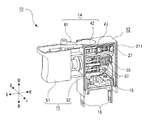
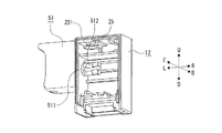
図1を参照すると、スイッチ10は、使用者によって操作されることにより電気回路の動作を制御するための信号を発生する装置である。前記スイッチ10は、以下を有する。
<筐体11>中空箱状であり、回路を収容する。前記回路は、前記電気回路に電気接続されてその一部をなす。前記筐体11は、ケース部材12と、カバー部材13とを有する。前記ケース部材12及び前記カバー部材13は、超音波溶着するなどして互いに固着され、これにより、ケース部材12とカバー部材13との間の隙間から塵芥などが筐体11のなかに侵入するのを防ぐ。
<可動部15>前記使用者に操作されてL−R方向に略平行な方向に沿って直線移動する。例えば、スイッチ10は、使用者が可動部15を引き込んだ量にしたがってモータに供給する電力を制御するなど、可動部15の位置にしたがって前記電気回路の動作を制御する信号を発生させる。前記信号は、前記電気回路の動作を直接制御するための制御信号であってもよいし、前記スイッチ10の外部に設けられ前記電気回路の動作を制御する制御回路に入力される検知信号であってもよい。前記制御信号及び前記検知信号は、例えば、回路の開閉によって表されるものであってもよいし、抵抗値など電気的特性値によって表されるものであってもよい。
<可動部14>使用者に操作されてU−D方向に略平行な軸を中心として回動し、前記回路を制御する。例えば、スイッチ10は、使用者が可動部14を回動させた位置にしたがって前記モータの回転方向を制御するなど、可動部14の位置にしたがって前記電気回路の動作を制御する信号を発生させる。
Referring to FIG. 1, a
<
<
<
図2を参照すると、前記スイッチ10は、更に、以下を有する。
<節度部27>前記ケース部材12のなかに配置されている。なお、前記節度部27は、前記ケース部材12と一体に形成されていてもよく、前記ケース部材12とは別部品であってもよい。
<付勢部材55>圧縮コイルばねなど、圧縮に対して復元力を発生する部材である。前記ケース部材12のなかに配置され、L−R方向に略平行な方向に沿って圧縮されることにより発生する復元力によって、前記可動部15をL方向へ向けて付勢する。
<二つの固定接片18>前記ケース部材12に嵌合され固定されている。前記固定接片18の一部は、前記筐体11の外に露出している。前記固定接片18には、外部の前記電気回路からの配線が電気接続される。
<可動接片19>前記可動部15の移動に伴って回動して、前記固定接片18の間を短絡/離間させる。
Referring to FIG. 2, the
<
<
<Two fixed
<
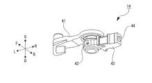
また、前記可動部14は、以下を有する。
<内部部材42>前記筐体11のなかに配置され、前記回路を作動させる。前記内部部材42には、可動接片47が固定されている。
<外部部材41>前記内部部材42とは別部品であり、前記内部部材42に固定されている。前記筐体11の外部に露出し、前記使用者によって操作される。
The
<
<
また、前記可動部15は、以下を有する。
<内部部材52>前記筐体11のなかに配置され、前記回路を作動させる。前記内部部材52には、二つの可動接片57が固定されている。
<外部部材51>前記内部部材52とは別部品である。前記筐体11の外部に露出し、前記使用者によって操作される。
The
<
<
図3を参照すると、前記スイッチ10は、更に、以下を有する。
<基板16>前記筐体11のなかに配置されている。前記基板16には、プリント回路などの回路61が形成されている。前記回路61は、前記可動接片47,57と接触/離間するなどして、前記可動部14,15の位置を検出する。前記基板16の一部は、前記筐体11の外に露出している。
<端子17>前記筐体11の外に配置され、半田付けなどにより前記基板16に固定され、前記回路61と電気接続している。前記端子17には、外部の前記電気回路からの配線が電気接続され、これにより、前記回路61を前記電気回路に電気接続する。
<パッキン62>環状のゴムなどの封止部材であり、前記基板16に巻き付けられている。これにより、前記基板16と前記筐体11との間の隙間から塵芥などが筐体11のなかに侵入するのを防ぐ。
Referring to FIG. 3, the
<
<
<
また、前記カバー部材13は、以下を有する。
<前面部34>F−B方向に略垂直な略長方形板状である。
<突条31>前記前面部34の外周に沿って、B側の面から突出している。前記突条31は、前記カバー部材13を前記ケース部材12に超音波溶着するための糊しろである。なお、前記カバー部材13のD側には、前記突条31が設けられていない箇所がある。これにより、前記ケース部材12との間に、前記基板16の一部を前記筐体11の外部に露出させるための隙間が形成される。
<二つの受け部35>U−D方向に略垂直な板状であり、前記前面部34のB側の面から突出している。前記受け部35の先端は、半円形凹状であり、これにより、前記可動部14と係合する。
The
<
<
<Two receiving
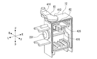
図4を参照すると、前記ケース部材12は、F側が開口した略直方体箱状であり、以下を有する。
<背面部24>F−B方向に略垂直な略長方形板状である。
<上側面部22>U−D方向に略垂直な略長方形板状であり、前記背面部24のU側の端からF方向に延びている。
<左側面部23>L−R方向に略垂直な略長方形板状であり、前記背面部24のL側の端からF方向に延びている。U側の端は、前記上側面部22のL側の端と連結している。
<右側面部28>L−R方向に略垂直な略長方形板状であり、前記背面部24のR側の端からF方向に延びている。U側の端は、前記上側面部22のR側の端と連結している。
<溝211>前記開口の外周に沿って、前記上側面部22・前記左側面部23・前記右側面部28のF側の端から凹設されている。前記溝211は、前記カバー部材13の前記突条31に対応し、前記突条31と溶着される。
<二つの受け部25>U−D方向に略垂直な板状であり、前記背面部24のF側の面から突出している。なお、もう一つの受け部25は、図12に示されている。前記受け部25の先端は、半円形凹状であり、これにより、前記可動部14と係合し、前記カバー部材13の前記受け部35と協働して、前記可動部14を回動可能に支持する。
<三つの案内部26>U−D方向に略垂直な板状であり、前記左側面部23から前記右側面部28までに亘って、前記背面部24のF側の面から突出している。前記案内部26は、前記可動部15と係合して、前記可動部15の直線移動を案内する。
Referring to FIG. 4, the
<Back
<
<
<Right
<Groove 211> Along the outer periphery of the opening, a recess is formed from the F-side end of the upper
<Two receiving
<Three
図7も合わせて参照すると、前記上側面部22は、以下を有する。
<貫通穴221>U−D方向に略平行な軸を中心とする略円形の穴であり、前記上側面部22を貫通している。前記上側面部22における位置は、F−B方向において略中央であり、L−R方向においてL側の端に近い。
<凹部222>前記上側面部22のU側の面から凹設されている。底面の形状は、略長方形と略円形とが結合した形状である。前記略円形の部分は、前記貫通穴221と略同軸である。前記略長方形の部分は、幅が前記略円形の部分の直径より小さく、前記略円形の部分と前記上側面部22のL側の端との間を繋いでいる。
<二つの環状突起224>前記凹部222の前記底面から突出している。中心は、前記貫通穴221の中心と略等しい。
Referring also to FIG. 7, the
<Through
<Recess 222> The
<Two
前記左側面部23は、以下を有する。
<貫通穴231>L−R方向に略平行な軸を中心とする略円形の穴であり、前記左側面部23を貫通している。
The
<Through
図5を参照すると、前記可動部14は、更に、以下を有する。
<固定部材43>前記外部部材41と前記内部部材42とを固定している。
<押し棒44>前記内部部材42のR側の端に配置され、L−R方向に略平行な方向に直線移動可能であり、前記節度部27と当接して協働し、前記可動部14を回動させたとき、クリック感を醸成する。
Referring to FIG. 5, the
<Fixing
<Push
図6を参照すると、前記外部部材41は、以下を有する。
<軸部411>U−D方向に略平行な軸を中心とする略円柱形状である。直径は、前記ケース部材12の前記貫通穴221の直径よりわずかに小さい。組み立てたとき、前記外部部材41は、軸部411を中心として回動する。F側に切欠412が設けられている。前記切欠412は、前記軸部411の側面を削って平らにした形状である。また、固定穴413が前記切欠412からF−B方向に略平行な方向に貫通している。
<円板部414>U−D方向に略垂直な略円形板状であり、前記軸部411と略同軸である。直径は、前記ケース部材12の前記凹部222の略円形の部分の直径よりもわずかに小さい。厚さは、前記ケース部材12の前記凹部222の深さと略等しい。組み立てたとき、前記円板部414のU側の面は、前記ケース部材12の前記上側面部22のU側の面と面一になる。ここに段差があると、塵芥が溜まり、筐体11の内部に侵入するかもしれないので、その可能性をなくすためである。
<二つの環状突起415>前記円板部414のD側の面から突出している。中心は、前記円板部414の中心と略等しい。組み立てたとき、環状突起415は、前記ケース部材12の前記環状突起224と互い違いに係合して、迷路構造を形成する。これにより、前記円板部414と前記凹部222との間の隙間から塵芥が筐体11のなかに侵入するのを防ぐ。
<操作部416>前記円板部414からL方向に略平行な方向に延びている。組み立てたとき、使用者は、前記操作部416を持って、前記可動部14を回動させる。このとき、前記ケース部材12の前記凹部222の側面に前記操作部416が当たることにより、前記可動部14の回動範囲が制限される。
Referring to FIG. 6, the
<
<
<Two
<
また、前記内部部材42は、以下を有する。
<円環部421>U−D方向に略平行な軸を中心とする略円筒形状である。前記円環部421のU方向及びD方向の端部付近は、中央部分よりも直径が小さく、前記ケース部材12及び前記カバー部材13の前記受け部25,35と係合して回動可能に支持される。前記円環部421には、略同軸に嵌合穴424が設けられている。前記嵌合穴424は、略円柱状であり、直径は、前記外部部材41の前記軸部411の直径よりもわずかに大きい。前記嵌合穴424のF側の内周には、前記軸部411の前記切欠412に対応する平面部425が設けられている。これにより、組み立てたとき、前記内部部材42と前記外部部材41とが係合し、前記固定部材43で固定されていなくても、前記内部部材42が前記外部部材41と一体となって回動する。また、前記円環部421のF側の外周には、切欠422が設けられている。前記切欠422は、組み立てるときに、前記平面部425がある位置を容易に識別できるようにするための目印である。また、固定穴423がF−B方向に略平行な方向に貫通している。前記固定穴423は、前記嵌合穴424と交わり、組み立てたとき、前記外部部材41の前記固定穴413と連通する。
<作動部426>前記円環部421からR方向に略平行な方向に延びている。前記作動部426のF側の側面には、可動接片47を固定するための係合部427が設けられている。また、前記作動部426のR側の先端には、挿入穴428がL方向へ向けて凹設されている。前記挿入穴428は、前記押し棒44を装着するための穴である。
The
<
<
前記固定部材43は、例えば板ばねを丸めて、わずかな隙間を残して略円筒状にしたものである。組み立てたとき、前記内部部材42及び前記外部部材41の固定穴423,413に挿嵌され、前記外部部材41と前記内部部材42とを固定する。
The fixing
また、前記可動部14は、更に、以下を有する。
<付勢部材45>圧縮コイルばねなど、圧縮に対して復元力を発生する部材である。前記挿入穴428のなかに配置され、L−R方向に略平行な方向に圧縮されることにより発生する復元力によって、前記押し棒44をR方向へ向けて付勢する。これにより、組み立てたとき、押し棒44の先端が節度部27に当接し、クリック感を醸成する。
The
<
図7及び8を参照して、前記可動部14を前記ケース部材12に組み付ける手順を説明する。
最初に、前記内部部材42の前記作動部426を持って、前記ケース部材12の開口から、前記内部部材42の前記円環部421を、前記ケース部材12のなかに挿入し、前記ケース部材12の前記受け部25に押し当てる。これにより、前記内部部材42の前記嵌合穴424が、前記ケース部材12の前記貫通穴221と略同軸に位置決めされる。
A procedure for assembling the
First, by holding the operating
次に、前記外部部材41の前記操作部416を持って、前記ケース部材12の前記貫通穴221から、前記外部部材41の前記軸部411を、前記ケース部材12のなかに挿入し、前記軸部411の先端を前記内部部材42の前記嵌合穴424に係合させる。
この状態において、前記外部部材41の前記操作部416のD側の面が、前記ケース部材12の前記上側面部22に当接しているので、前記外部部材41は、前記固定穴413が前記固定穴423と連通する位置まで至っていない。しかし、前記軸部411の先端が前記嵌合穴424に係合しているので、前記外部部材41を回動させると、前記内部部材42は、前記外部部材41と一体となって回動する。このため、前記内部部材42の先端を前記ケース部材12から外に露出させることが容易にでき、前記挿入穴428に前記付勢部材45や前記押し棒44を挿入するなどの組み立て作業が容易にできる。
Next, by holding the
In this state, since the D-side surface of the
その後、前記外部部材41を回動させて、L−R方向に略平行にすると、前記凹部222に前記作動部416が嵌まり、前記外部部材41を更にD方向へ移動させることができるようになる。これにより、前記固定穴413が前記固定穴423と連通するので、ここに前記固定部材43を挿嵌することにより、前記外部部材41を前記内部部材42に固定する。
Thereafter, when the
図9を参照すると、前記外部部材51は、以下を有する。
<軸部511>L−R方向に略平行な方向に延びる略円柱状である。直径は、前記ケース部材12の前記貫通穴231の直径よりわずかに小さい。組み立てたとき、前記外部部材51は、前記軸部511に沿って直線移動する。前記軸部511のR側の先端には、前記内部部材52と係合するための係合部512が設けられている。
<操作部516>前記軸部511のL側の端に設けられている。組み立てたとき、使用者は、前記操作部516を握って、前記可動部15をR方向へ向けて移動させる。使用者が前記操作部516を握る力を緩めると、前記付勢部材55の付勢力により、前記可動部15がL方向に押し戻される。
Referring to FIG. 9, the
<
<
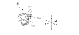
また、前記内部部材52は、以下を有する。
<作動部526>略直方体箱状であり、R側及びB側が開口している。前記付勢部材55は、前記作動部526のなかに係合する。
<係合部522(当接部)>前記作動部526のL側に設けられている。前記外部部材51の前記係合部512と係合して、前記内部部材52を前記外部部材51に固定する。
The
<
<Engaging portion 522 (contact portion)> Provided on the L side of the operating
図10を参照すると、前記軸部511は、中心軸に沿って貫通する穴514を有する。
前記係合部512は、前記軸部511のR側の先端付近を、F−B方向に略垂直な平面で切断し、B側の部分だけを残した略弓形柱形状である。切断平面は、R側の最先端の部分では、前記中心軸よりもF側にあり、それよりもL側の部分では、前記中心軸よりもB側にあり、これにより、突出部513が形成されている。
Referring to FIG. 10, the
The
図11を参照すると、前記係合部522は、前記係合部512に対応した形状であり、前記軸部511と略同一直径の円柱を、F−B方向に略垂直な平面で切断し、F側の部分だけを残した略弓形柱形状である。切断平面は、L側の最先端の部分では、前記中心軸よりもB側にあり、それよりもR側の部分では、前記中心軸よりもF側にあり、これにより、突出部523が形成されている。
また、前記係合部522は、前記作動部526のなかに連通した穴524を有する。前記穴524は、組み立てたとき、前記穴514と連通する。
Referring to FIG. 11, the engaging
Further, the engaging
図12を参照して、前記可動部15を前記ケース部材12に組み付ける手順を説明する。
最初に、前記外部部材51の前記操作部516を持って、前記ケース部材12の前記貫通穴231から、前記外部部材51の前記軸部511を、前記ケース部材12のなかに挿入し、前記係合部512を前記ケース部材12のなかに露出させる。
次に、前記内部部材52を、前記ケース部材12の開口から、前記ケース部材12のなかに挿入し、前記内部部材52の前記係合部522を、図9に示すように、前記係合部512に係合させる。これにより、前記外部部材51と前記内部部材52とが一体化するので、前記外部部材51がL方向に抜け落ちるのを防ぐことができる。また、前記外部部材51をR方向に移動させると、前記係合部512が前記係合部522を押圧し、前記内部部材52が前記外部部材51と一体となってR方向に移動する。
A procedure for assembling the
First, by holding the
Next, the
図13〜16は、前記可動部15の別の実施形態を示す。
図13を参照すると、前記外部部材51の前記軸部511は、前記操作部516(不図示)とは別部品であり、前記操作部516に固定される。また、前記外部部材51と前記内部部材52とが係合する係合部512,522の形状が、図9〜12と異なっている。
13 to 16 show another embodiment of the
Referring to FIG. 13, the
図14を参照すると、前記係合部512は、前記軸部511のR側の先端付近を、F−B方向に略垂直な平面で切断し、B側の部分だけを残した略弓形柱形状である。前記切断平面は、前記軸部511の前記中心軸よりもF側にある。R側の最先端の部分よりもL側の部分は、更に、U−D方向に略垂直な平面で、U側及びD側の部分を切断し、これにより、突出部513が形成されている。
Referring to FIG. 14, the
図15を参照すると、前記係合部522は、前記作動部526のなかに凹設されている。前記係合部522は、前記係合部512に対応した形状であり、L側の入口のU側及びD側に突出部523が形成されている。
Referring to FIG. 15, the engaging
図16を参照して、前記可動部15を前記ケース部材12に組み付ける手順を説明する。
最初に、前記軸部511のL側の端を持って、前記ケース部材12の前記貫通穴231から、前記軸部511のR側の端を、前記ケース部材12のなかに挿入し、前記係合部512を前記ケース部材12のなかに露出させる。
次に、前記内部部材52を、前記ケース部材12の開口から、前記ケース部材12のなかに挿入し、前記内部部材52の前記係合部522を、図13に示すように、前記係合部512に係合させる。
A procedure for assembling the
First, holding the L-side end of the
Next, the
このように、前記係合部512は、L方向から前記貫通穴231に挿通して、前記ケース部材12のなかに露出させることができ、前記係合部522は、その後、前記ケース部材12の開口から、前記ケース部材12のなかに挿入して、前記ケース部材12のなかに露出した前記係合部512に係合させることができる形状であればよい。
In this manner, the engaging
図17〜19は、前記可動部15の更に別の実施形態を示す。
図17を参照して、前記外部部材51の前記係合部512は、前記軸部511の先端付近を一周する溝である。前記係合部512は、前記内部部材52と係合するのではなく、抜止部材53と係合する。
前記抜止部材53は、Eリングなど、前記係合部512と係合して前記軸部511に固定される部材である。前記抜止部材53の外径は、前記ケース部材12の前記貫通穴231の内径よりも大きい。これにより、組み立てたとき、前記外部部材51がL方向に抜け落ちるのを防ぐ。
17 to 19 show still another embodiment of the
Referring to FIG. 17, the
The retaining
図18を参照して、前記内部部材52は、前記係合部522に代えて、受圧部521(当接部)を有する。組み立てたとき、前記軸部511の先端が前記受圧部521に当接する。
Referring to FIG. 18, the
図19を参照して、前記可動部15を前記ケース部材12に組み付ける手順を説明する。
最初に、前記外部部材51の前記操作部516を持って、前記ケース部材12の前記貫通穴231から、前記外部部材51の前記軸部511を、前記ケース部材12のなかに挿入し、前記係合部512を前記ケース部材12のなかに露出させる。
次に、前記抜止部材53を、前記ケース部材12の開口から、前記ケース部材12のなかに挿入し、前記係合部512に係合させる。これにより、前記外部部材51と前記抜止部材53とが一体化するので、前記外部部材51がL方向に抜け落ちるのを防ぐことができる。
その後、前記内部部材52を、前記ケース部材12の開口から、前記ケース部材12のなかに挿入する。
前記内部部材52が前記付勢部材55によってL方向に付勢されるので、前記軸部511の先端が前記受圧部521に当接する。使用者が前記操作部516を握ると、前記外部部材51がR方向に移動し、前記軸部511の先端が前記受圧部521を押圧して、前記内部部材52が前記外部部材51とともにR方向に移動する。
A procedure for assembling the
First, by holding the
Next, the retaining
Then, the
Since the
このように、前記外部部材51と前記内部部材52とは、一体となって移動することができれば、係合していなくてもよい。
As described above, the
以上説明した実施形態は、本発明の理解を容易にするための例である。本発明は、これに限定されるものではなく、添付の特許請求の範囲によって定義される範囲から逸脱することなく様々に修正し、変更し、追加し、又は除去したものを含む。これは、以上の説明から当業者に容易に理解することができる。 The embodiment described above is an example for facilitating the understanding of the present invention. The present invention is not limited thereto, but includes various modifications, changes, additions, or omissions without departing from the scope defined by the appended claims. This can be easily understood by those skilled in the art from the above description.
10 スイッチ、11 筐体、12 ケース部材、13 カバー部材、14,15 可動部、16 基板、17 端子、18 固定接片、19,47,57 可動接片、211 溝、22 上側面部、221,231 貫通穴、222 凹部、224,415 環状突起、23 左側面部、24 背面部、25,35 受け部、26 案内部、27 節度部、28 右側面部、31 突条、34 前面部、41,51 外部部材、411,511 軸部、412,422 切欠、413,423 固定穴、414 円板部、416,516 操作部、42,52 内部部材、421 円環部、424 嵌合穴、425 平面部、426,526 作動部、427 係合部、428 挿入穴、521 受圧部、43 固定部材、44 押し棒、45,55 付勢部材、512,522 係合部、513,523 突出部、514,524 穴、53 抜止部材、61 回路、62 パッキン。
DESCRIPTION OF
Claims (8)
前記筐体の内部に設けられた回路と、
使用者に操作されて前記回路を制御する可動部と
を備えたスイッチにおいて、
前記筐体は、
前面が開口したケース部材と、
前記ケース部材の前面の開口を塞ぐよう前記ケース部材に固着されたカバー部材と
を有し、
前記ケース部材は、側面を貫通する貫通穴を有し、
前記可動部は、
前記筐体の内部に配置され、前記回路を制御する内部部材と、
前記内部部材とは別部品であって、前記筐体の外部に露出して、前記使用者に操作される外部部材と
を有し、
前記外部部材は、前記貫通穴に挿通された軸部を有する、
スイッチ。 A hollow box-shaped housing,
A circuit provided inside the housing,
A switch having a movable part operated by a user to control the circuit,
The housing is
A case member with an open front,
A cover member fixed to the case member so as to close an opening on a front surface of the case member,
The case member has a through hole penetrating a side surface,
The movable part is
An internal member that is arranged inside the housing and controls the circuit;
The internal member is a separate component, having an external member exposed to the outside of the housing and operated by the user,
The external member has a shaft portion inserted through the through hole,
switch.
前記内部部材は、
前記軸部の一方の端が挿入される嵌合穴を有し、
前記嵌合穴と前記軸部の一方の端とが嵌合することにより、前記内部部材は、前記外部部材と一体となって回動する、
請求項1のスイッチ。 The movable portion rotates around the shaft portion,
The internal member,
A fitting hole into which one end of the shaft portion is inserted,
By fitting the fitting hole and one end of the shaft portion, the internal member rotates integrally with the external member,
The switch of claim 1.
前記外部部材と前記内部部材とを固定する固定部材を有し、
前記外部部材は、更に、
前記軸部の他方の端に設けられた円板部を有し、
前記固定部材によって前記外部部材と前記内部部材とを固定した状態において、前記円板部と、前記ケース部材の前記側面との間に迷路構造が形成されている、
請求項2のスイッチ。 The movable part further comprises:
A fixing member for fixing the external member and the internal member,
The external member further includes:
A disk portion provided at the other end of the shaft portion,
In a state where the outer member and the inner member are fixed by the fixing member, a maze structure is formed between the disc portion and the side surface of the case member.
The switch according to claim 2.
前記貫通穴の周囲に設けられ前記円板部と係合する凹部を有し、
前記円板部の表面は、前記ケース部材の前記側面と略面一である、
請求項3のスイッチ。 The case member further comprises:
Having a recess provided around the through hole and engaging with the disc portion,
The surface of the disc portion is substantially flush with the side surface of the case member.
The switch according to claim 3.
請求項3又は4のスイッチ。 In a state in which the external member and the internal member are not fixed by the fixing member, the external member is moved relative to the internal member while maintaining the fitting of the fitting hole and one end of the shaft portion. Can be moved in the axial direction,
The switch according to claim 3 or 4.
中心に前記嵌合穴が設けられた円環部と、
前記円環部から径方向に延びた作動部と
を有し、
前記ケース部材の前面の開口が前記カバー部材で塞がれていない状態において、前記嵌合穴と前記軸部の一方の端とを嵌合させ、前記外部部材を回動させることにより、前記作動部の先端を前記ケース部材の前面の開口から外側へ露出させることができる、
請求項5のスイッチ。 The internal member further comprises:
An annular portion provided with the fitting hole at the center,
An operating portion extending radially from the annular portion,
In a state in which the opening on the front surface of the case member is not closed by the cover member, the fitting hole and one end of the shaft portion are fitted to each other, and the external member is rotated, thereby performing the operation. The tip of the portion can be exposed to the outside from the opening on the front surface of the case member,
The switch according to claim 5.
内側に前記円環部と係合する受け部を有し、
前記受け部に前記円環部を係合させることにより、前記嵌合穴を前記貫通穴と略同軸に位置決めすることができる、
請求項6のスイッチ。 The case member,
Having a receiving portion engaged with the annular portion on the inside,
By engaging the annular portion with the receiving portion, the fitting hole can be positioned substantially coaxially with the through hole.
The switch according to claim 6.
前記内部部材は、
前記軸部に当接する当接部を有し、
前記外部部材を前記筐体の内側へ向けて直線移動させると、前記軸部が前記当接部を押圧することにより、前記内部部材が、前記外部部材と一体となって直線移動する、
請求項1のスイッチ。 The movable section linearly moves along the axial direction of the shaft section,
The internal member,
Having a contact portion that contacts the shaft portion,
When the external member is linearly moved toward the inside of the housing, the shaft portion presses the contact portion, so that the internal member linearly moves integrally with the external member.
The switch of claim 1.
Priority Applications (4)
| Application Number | Priority Date | Filing Date | Title |
|---|---|---|---|
| JP2018124637A JP6838012B2 (en) | 2018-06-29 | 2018-06-29 | switch |
| EP19170861.9A EP3591681B1 (en) | 2018-06-29 | 2019-04-24 | Switch |
| US16/392,939 US10707030B2 (en) | 2018-06-29 | 2019-04-24 | Switch |
| CN201910503518.XA CN110660598A (en) | 2018-06-29 | 2019-06-12 | Switch with a switch body |
Applications Claiming Priority (1)
| Application Number | Priority Date | Filing Date | Title |
|---|---|---|---|
| JP2018124637A JP6838012B2 (en) | 2018-06-29 | 2018-06-29 | switch |
Publications (2)
| Publication Number | Publication Date |
|---|---|
| JP2020004645A true JP2020004645A (en) | 2020-01-09 |
| JP6838012B2 JP6838012B2 (en) | 2021-03-03 |
Family
ID=66251692
Family Applications (1)
| Application Number | Title | Priority Date | Filing Date |
|---|---|---|---|
| JP2018124637A Active JP6838012B2 (en) | 2018-06-29 | 2018-06-29 | switch |
Country Status (4)
| Country | Link |
|---|---|
| US (1) | US10707030B2 (en) |
| EP (1) | EP3591681B1 (en) |
| JP (1) | JP6838012B2 (en) |
| CN (1) | CN110660598A (en) |
Families Citing this family (1)
| Publication number | Priority date | Publication date | Assignee | Title |
|---|---|---|---|---|
| JP2022046337A (en) * | 2020-09-10 | 2022-03-23 | オムロン株式会社 | Trigger switch |
Family Cites Families (9)
| Publication number | Priority date | Publication date | Assignee | Title |
|---|---|---|---|---|
| US4864083A (en) | 1988-04-15 | 1989-09-05 | Lucerne Products, Inc. | Reversing switch |
| US7705260B2 (en) * | 2005-04-18 | 2010-04-27 | Xinsheng Xu | Switch assembly |
| JP4696670B2 (en) * | 2005-05-02 | 2011-06-08 | オムロン株式会社 | Trigger switch |
| JP2009199981A (en) * | 2008-02-25 | 2009-09-03 | Satori S-Tech Co Ltd | Switch for electric power tool |
| JP5215890B2 (en) * | 2009-01-28 | 2013-06-19 | 佐鳥エス・テック株式会社 | Trigger switch |
| JP5898993B2 (en) | 2011-03-15 | 2016-04-06 | 株式会社マキタ | Trigger switch for electric tools |
| JP5884450B2 (en) * | 2011-12-01 | 2016-03-15 | オムロン株式会社 | Trigger switch |
| JP6277668B2 (en) * | 2013-02-14 | 2018-02-14 | オムロン株式会社 | Operation lever seal structure and power tool using the same |
| JP6399066B2 (en) * | 2016-09-27 | 2018-10-03 | オムロン株式会社 | Trigger switch |
-
2018
- 2018-06-29 JP JP2018124637A patent/JP6838012B2/en active Active
-
2019
- 2019-04-24 EP EP19170861.9A patent/EP3591681B1/en active Active
- 2019-04-24 US US16/392,939 patent/US10707030B2/en active Active
- 2019-06-12 CN CN201910503518.XA patent/CN110660598A/en active Pending
Also Published As
| Publication number | Publication date |
|---|---|
| CN110660598A (en) | 2020-01-07 |
| EP3591681A1 (en) | 2020-01-08 |
| EP3591681B1 (en) | 2022-05-04 |
| US10707030B2 (en) | 2020-07-07 |
| US20200006019A1 (en) | 2020-01-02 |
| JP6838012B2 (en) | 2021-03-03 |
Similar Documents
| Publication | Publication Date | Title |
|---|---|---|
| JP3222714B2 (en) | Pressing and rotating electronic parts | |
| JP3952642B2 (en) | Press / rotate electronic components | |
| US9916944B2 (en) | Contact mechanism having movable contact pieces, trigger switch and electric tool with same | |
| JP2006310441A (en) | Rotary electronic component | |
| JP2008073779A (en) | Trigger switch | |
| JP4019601B2 (en) | Lever switch | |
| JPH09274830A (en) | Combined control electric component | |
| JP4217531B2 (en) | Switch device | |
| JP6838012B2 (en) | switch | |
| JP2011183523A (en) | Trigger switch | |
| EP3432332A1 (en) | Trigger switch and electrical tool using same | |
| JP4338722B2 (en) | Input device | |
| JP2007035402A (en) | Operation mechanism of electric device | |
| JP2001322074A (en) | Dustproof device for toggle switch, and power tool with dustproof device | |
| JP2013175349A (en) | Switching device | |
| JP2000311551A (en) | Slide operation type switch | |
| JP6563356B2 (en) | Slide switch | |
| JP3857621B2 (en) | Composite operation type electric parts | |
| JP4619196B2 (en) | Sliding electronic parts with pressure switch | |
| JP3157249U (en) | switch | |
| JP4044310B2 (en) | Rotary pulse switch | |
| JP2024039829A (en) | trigger switch | |
| JP4484693B2 (en) | Electronic component mounting structure and rotary electronic component | |
| JP2007305363A (en) | Slide operation type electric component | |
| JP2001067986A (en) | Composite operation switch |
Legal Events
| Date | Code | Title | Description |
|---|---|---|---|
| A621 | Written request for application examination |
Free format text: JAPANESE INTERMEDIATE CODE: A621 Effective date: 20200604 |
|
| A871 | Explanation of circumstances concerning accelerated examination |
Free format text: JAPANESE INTERMEDIATE CODE: A871 Effective date: 20200604 |
|
| A975 | Report on accelerated examination |
Free format text: JAPANESE INTERMEDIATE CODE: A971005 Effective date: 20200904 |
|
| A131 | Notification of reasons for refusal |
Free format text: JAPANESE INTERMEDIATE CODE: A131 Effective date: 20200915 |
|
| A521 | Request for written amendment filed |
Free format text: JAPANESE INTERMEDIATE CODE: A523 Effective date: 20201020 |
|
| TRDD | Decision of grant or rejection written | ||
| A01 | Written decision to grant a patent or to grant a registration (utility model) |
Free format text: JAPANESE INTERMEDIATE CODE: A01 Effective date: 20210119 |
|
| A61 | First payment of annual fees (during grant procedure) |
Free format text: JAPANESE INTERMEDIATE CODE: A61 Effective date: 20210210 |
|
| R150 | Certificate of patent or registration of utility model |
Ref document number: 6838012 Country of ref document: JP Free format text: JAPANESE INTERMEDIATE CODE: R150 |
|
| R250 | Receipt of annual fees |
Free format text: JAPANESE INTERMEDIATE CODE: R250 |