JP2020001790A - Two-part mixing container and two-part mixing jetting container - Google Patents
Two-part mixing container and two-part mixing jetting container Download PDFInfo
- Publication number
- JP2020001790A JP2020001790A JP2018125143A JP2018125143A JP2020001790A JP 2020001790 A JP2020001790 A JP 2020001790A JP 2018125143 A JP2018125143 A JP 2018125143A JP 2018125143 A JP2018125143 A JP 2018125143A JP 2020001790 A JP2020001790 A JP 2020001790A
- Authority
- JP
- Japan
- Prior art keywords
- container
- content liquid
- pump chamber
- cylinder
- port
- Prior art date
- Legal status (The legal status is an assumption and is not a legal conclusion. Google has not performed a legal analysis and makes no representation as to the accuracy of the status listed.)
- Granted
Links
Images



Landscapes
- Package Specialized In Special Use (AREA)
Abstract
【課題】振って混ぜる必要性を低減できる二液混合容器を提供する。【解決手段】二液混合容器1は、蓄圧ポンプ3を備える第1容器1aと第2容器1bとを備え、第1容器1aは、第2容器1bに収容された第2内容液C2に第1内容液C1を混合するために倒立姿勢で使用され、蓄圧ポンプ3は、吸込口5とシリンダ6とを有する固定部7と、第2容器本体4の口部4aに押当てられる押当て部8とピストン9と噴出口10とを有するとともに固定部7に対して進退可能な作動部11と、固定部7と作動部11とによって、吸込口5から噴出口10までの流路Rに区画されるポンプ室12と、を備え、作動部11は、貫通口24を有する周壁25を有する中空棒状部26と、ピストン9に一体に連結するとともに、中空棒状部26に対して前進することでポンプ室12と貫通口24との連通を遮断する開閉部27と、開閉部27を中空棒状部26に対して前進方向に付勢する弾性体29と、を備える。【選択図】図1PROBLEM TO BE SOLVED: To provide a two-liquid mixing container capable of reducing the need for shaking and mixing. A two-liquid mixing container 1 includes a first container 1a and a second container 1b including an accumulator pump 3, and the first container 1a is a second content liquid C2 housed in a second container 1b. 1 Used in an inverted position to mix the content liquid C1, the accumulator pump 3 has a fixing portion 7 having a suction port 5 and a cylinder 6, and a pressing portion pressed against the mouth portion 4a of the second container body 4. An operating portion 11 having an 8, piston 9, and an ejection port 10 and capable of advancing and retreating with respect to the fixing portion 7, and the fixing portion 7 and the operating portion 11 partition the flow path R from the suction port 5 to the ejection port 10. The pump chamber 12 is provided, and the operating portion 11 is integrally connected to the hollow rod-shaped portion 26 having the peripheral wall 25 having the through port 24, and is advanced with respect to the hollow rod-shaped portion 26. An opening / closing portion 27 that cuts off communication between the pump chamber 12 and the through port 24, and an elastic body 29 that urges the opening / closing portion 27 in the forward direction with respect to the hollow rod-shaped portion 26 are provided. [Selection diagram] Fig. 1
Description
本発明は、二液混合容器及び二液混合用噴出容器に関する。 The present invention relates to a two-liquid mixing container and a two-liquid mixing ejection container.
第1内容液を収容する第1容器と第2内容液を収容する第2容器とを備え、第2内容液に第1内容液を混合するために第1容器が倒立姿勢で使用される二液混合容器としては、例えば特許文献1に記載されるようなものが知られている。特許文献1に記載される二液混合容器は、倒立姿勢にした第1容器の口部を正立姿勢の第2容器の口部に取り付け、第1内容液の自重によって第1内容液を第2容器に導入するように構成されている。
A second container for storing the first content liquid and a second container for storing the second content liquid, wherein the first container is used in an inverted posture to mix the first content liquid with the second content liquid; As a liquid mixing container, for example, one described in
前述したような従来の二液混合容器は、第1内容液を第2容器の内部に導入した後に第2容器を振って混ぜる必要があり、使用性に改善の余地があった。また、例えば炭酸などの振って混ぜることが困難な内容液に対して混合する場合には、できるだけ振らずに混合できることが望ましい。 In the conventional two-liquid mixing container as described above, it is necessary to shake the second container after introducing the first content liquid into the second container, and there is room for improvement in usability. In addition, for example, when mixing with a content liquid that is difficult to mix by shaking with carbon dioxide or the like, it is desirable that mixing can be performed without shaking as much as possible.
本発明の目的は、振って混ぜる必要性を低減でき、容易に混合可能な二液混合容器及び二液混合用噴出容器を提供することにある。 An object of the present invention is to provide a two-liquid mixing container and a two-liquid mixing ejection container that can reduce the necessity of shaking and mixing and can be easily mixed.
本発明の一態様に係る二液混合容器は、
第1内容液を収容する収容空間に連なる筒状の口部を有する第1容器本体と蓄圧ポンプとを備える第1容器と、
第2内容液を収容する収容空間に連なる筒状の口部を有する第2容器本体を備える第2容器と、を備え、
前記第1容器は、前記第2容器に収容された前記第2内容液に前記第1内容液を混合するために倒立姿勢で使用され、
前記蓄圧ポンプは、
前記第1容器本体の前記口部に固定されるとともに前記第1内容液の吸込口とシリンダとを有する固定部と、
前記第2容器本体の前記口部に押当てられる押当て部と前記シリンダの内周面を摺動可能なピストンと前記第1内容液の噴出口とを有するとともに前記固定部に対して前記シリンダの軸方向に進退可能な作動部と、
前記固定部と前記作動部とによって、前記吸込口から前記噴出口までの流路に区画されるとともに、前記作動部の前進によって容積が減少し、前記作動部の後退によって容積が増加するポンプ室と、
前記ポンプ室より上流側に位置する逆流防止部と、を備え、
前記作動部は、
貫通口を有する周壁を有するとともに前記貫通口及び前記周壁の内側空間によって前記流路の一部を形成する中空棒状部と、
前記ピストンに一体に連結するとともに、前記中空棒状部に対して前記軸方向に前進することで前記ポンプ室と前記貫通口との連通を遮断する一方、前記中空棒状部に対して前記軸方向に後退することで前記ポンプ室と前記貫通口とを連通させる開閉部と、
前記開閉部を前記中空棒状部に対して前進方向に付勢する弾性体と、を備える。
The two-liquid mixing container according to one embodiment of the present invention,
A first container including a first container body having a cylindrical mouth portion connected to a storage space for storing the first content liquid, and a pressure accumulation pump;
A second container provided with a second container body having a cylindrical mouth portion connected to a storage space for storing the second content liquid,
The first container is used in an inverted posture to mix the first content liquid with the second content liquid contained in the second container,
The accumulator pump,
A fixing portion fixed to the mouth portion of the first container body and having a suction port for the first content liquid and a cylinder;
A cylinder having a pressing portion pressed against the mouth of the second container body, a piston slidable on an inner peripheral surface of the cylinder, and an ejection port for the first content liquid; An actuating part that can advance and retreat in the axial direction of
A pump chamber partitioned by the fixed portion and the operating portion into a flow path from the suction port to the jet port, and having a volume reduced by advancing the operating portion and increasing by a retreat of the operating portion. When,
A backflow prevention unit located upstream of the pump chamber,
The actuation unit is
A hollow rod-shaped portion having a peripheral wall having a through hole and forming a part of the flow path by the inner space of the through hole and the peripheral wall,
While being integrally connected to the piston, it is possible to cut off the communication between the pump chamber and the through port by advancing in the axial direction with respect to the hollow rod-shaped portion, while in the axial direction with respect to the hollow rod-shaped portion. An opening / closing unit that allows the pump chamber and the through hole to communicate with each other by retreating,
An elastic body that urges the opening / closing portion in the forward direction with respect to the hollow rod-shaped portion.
本発明に係る二液混合容器は、
前記作動部が、
前記中空棒状部を有する棒状部材と、
前記ピストン及び前記開閉部を有するピストン部材と、
前記棒状部材に取付けられるとともに前記押当て部を有する押当て部材と、を備えてもよい。
The two-liquid mixing container according to the present invention,
The actuation unit,
A rod-shaped member having the hollow rod-shaped portion,
A piston member having the piston and the opening and closing unit,
A pressing member attached to the rod-shaped member and having the pressing portion.
本発明に係る二液混合容器は、
前記ピストン部材が、後方に向けて径方向内側に傾斜する傾斜面を有してもよく、
前記弾性体が、前記押当て部材に設けられるとともに前記傾斜面を径方向内側に押圧する片持ち弾性片で構成されてもよい。
The two-liquid mixing container according to the present invention,
The piston member may have an inclined surface that is inclined radially inward toward the rear,
The elastic body may be constituted by a cantilevered elastic piece provided on the pressing member and pressing the inclined surface radially inward.
本発明に係る二液混合容器は、前記ポンプ室の内部に、空気を前記ポンプ室の内圧の昇降に応じて伸縮可能に収容する空気室が設けられていてもよい。 In the two-liquid mixing container according to the present invention, an air chamber may be provided inside the pump chamber so as to expand and contract air in accordance with an increase and decrease in the internal pressure of the pump chamber.
本発明に係る二液混合容器は、
前記固定部が、前記逆流防止部を構成する弁体を有する弁部材を備えてもよく、
前記弁部材が、前記空気室を内側に区画する有頂筒状の包囲壁を備えてもよい。
The two-liquid mixing container according to the present invention,
The fixing portion may include a valve member having a valve body constituting the backflow prevention portion,
The valve member may include a topped cylindrical surrounding wall that partitions the air chamber inside.
本発明に係る二液混合容器は、前記包囲壁の下端によって形成された開口を被覆するとともに前記空気室と前記ポンプ室とを連通させる連通口を有する連通口付き蓋を備えてもよい。 The two-liquid mixing container according to the present invention may include a lid with a communication port that covers an opening formed by a lower end of the surrounding wall and has a communication port that connects the air chamber and the pump chamber.
本発明に係る二液混合容器は、前記空気室を密封した状態で前記包囲壁の内周面に対して摺動可能な摺動部材を備えてもよい。 The two-liquid mixing container according to the present invention may include a sliding member slidable on the inner peripheral surface of the surrounding wall while the air chamber is sealed.
本発明に係る二液混合容器は、前記第1容器本体が、前記第1内容液を空気と置換することなく前記蓄圧ポンプの前記噴出口から噴出可能な密封容器であってもよい。 The two-liquid mixing container according to the present invention may be a sealed container in which the first container main body can be ejected from the ejection port of the pressure accumulation pump without replacing the first content liquid with air.
本発明の一態様に係る二液混合用噴出容器は、
内容液を収容する収容空間に連なる筒状の口部を有する容器本体と蓄圧ポンプとを備え、
前記内容液を他の容器の容器本体が有する筒状の口部に連なる収容空間に収容された他の内容液に混合するために倒立姿勢で使用され、
前記蓄圧ポンプは、
前記容器本体の前記口部に固定されるとともに前記内容液の吸込口とシリンダとを有する固定部と、
前記他の容器本体の前記口部に押当てられる押当て部と前記シリンダの内周面を摺動可能なピストンと前記内容液の噴出口とを有するとともに前記固定部に対して前記シリンダの軸方向に進退可能な作動部と、
前記固定部と前記作動部とによって、前記吸込口から前記噴出口までの流路に区画されるとともに、前記作動部の前進によって容積が減少し、前記作動部の後退によって容積が増加するポンプ室と、
前記ポンプ室より上流側に位置する逆流防止部と、を備え、
前記作動部は、
貫通口を有する周壁を有するとともに前記貫通口及び前記周壁の内側空間によって前記流路の一部を形成する中空棒状部と、
前記ピストンに一体に連結するとともに、前記中空棒状部に対して前記軸方向に前進することで前記ポンプ室と前記貫通口との連通を遮断する一方、前記中空棒状部に対して前記軸方向に後退することで前記ポンプ室と前記貫通口とを連通させる開閉部と、
前記開閉部を前記中空棒状部に対して前進方向に付勢する弾性体と、を備える。
The two-liquid mixing ejection container according to one embodiment of the present invention,
A container main body having a cylindrical mouth portion connected to the storage space for storing the content liquid, and a pressure accumulation pump,
The content liquid is used in an inverted posture to be mixed with another content liquid stored in a storage space connected to a cylindrical mouth portion of a container body of another container,
The accumulator pump,
A fixed portion fixed to the mouth of the container body and having a suction port and a cylinder for the content liquid,
The container has a pressing portion pressed against the mouth portion of the other container body, a piston slidable on the inner peripheral surface of the cylinder, and a discharge port for the content liquid, and the shaft of the cylinder with respect to the fixed portion. An operating part that can move back and forth in the direction,
A pump chamber partitioned by the fixed portion and the operating portion into a flow path from the suction port to the jet port, and having a volume reduced by advancing the operating portion and increasing by a retreat of the operating portion. When,
A backflow prevention unit located upstream of the pump chamber,
The actuation unit is
A hollow rod-shaped portion having a peripheral wall having a through hole and forming a part of the flow path by the inner space of the through hole and the peripheral wall,
While being integrally connected to the piston, it is possible to cut off the communication between the pump chamber and the through port by advancing in the axial direction with respect to the hollow rod-shaped portion, while in the axial direction with respect to the hollow rod-shaped portion. An opening / closing unit that allows the pump chamber and the through hole to communicate with each other by retreating,
An elastic body that urges the opening / closing portion in the forward direction with respect to the hollow rod-shaped portion.
本発明によれば、振って混ぜる必要性を低減でき、容易に混合可能な二液混合容器及び二液混合用噴出容器を提供することができる。 ADVANTAGE OF THE INVENTION According to this invention, the necessity of shaking and mixing can be reduced, and the two-liquid mixing container and the jet container for two-liquid mixing which can be easily mixed can be provided.
以下、図面を参照して、本発明の実施形態に係る二液混合容器及び二液混合用噴出容器について詳細に例示説明する。なお、上下方向は、第1容器については倒立状態を基準とし、第2容器については正立状態を基準とする。すなわち、第1容器について上方とは、例えば図1における上方を意味し、下方とはその反対方向を意味する。また、第2容器について上方とは、例えば図3における上方を意味し、下方とはその反対方向を意味する。また、単に「軸方向」というときは、後述するシリンダの軸方向を意味する。同様に、単に「径方向」というときは、シリンダの径方向を意味する。 Hereinafter, a two-liquid mixing container and a two-liquid mixing ejection container according to an embodiment of the present invention will be described in detail with reference to the drawings. In the vertical direction, the first container is based on the inverted state, and the second container is based on the upright state. That is, the upper side of the first container means, for example, the upper side in FIG. 1, and the lower side means the opposite direction. In addition, the upper side of the second container means, for example, the upper side in FIG. 3, and the lower side means the opposite direction. Further, the term “axial direction” means the axial direction of a cylinder described later. Similarly, the term “radial direction” simply means the radial direction of the cylinder.
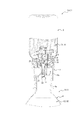
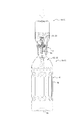
図1〜図3に示すように、本実施形態に係る二液混合容器1は、第1容器(本実施形態に係る二液混合用噴出容器)1aと第2容器1bとを備えている。第1容器1aは、図1に示すように、不使用時には倒立姿勢で保管できるように構成されている。また、第1容器1aは、図2〜図3に示すように、第2容器1bに収容された第2内容液C2に、第1容器1aに収容された第1内容液C1を混合するために、倒立姿勢で使用されるように構成されている。
As shown in FIGS. 1 to 3, the two-
図1に示すように、第1容器1aは、第1容器本体2と蓄圧ポンプ3とを備えている。第1容器本体2は、円筒状の口部2aと、口部2aに連なる胴部2bと、胴部2bに連なる底部2cとを有するボトル形状をなしている。しかし、第1容器本体2の形状は適宜変更が可能であり、例えば、第1容器本体2はチューブ形状をなしていてもよい。第1容器本体2の内側には、第1内容液C1を収容する収容空間S1が形成されている。口部2aは収容空間S1に連なっている。口部2aの外周面には、蓄圧ポンプ3を螺合によって取付けるための雄ねじが設けられている。しかし、口部2aの外周面には、このような雄ねじに替えて、蓄圧ポンプ3を打栓によって取付けるための凸部又は凹部が設けられてもよい。
As shown in FIG. 1, the
第1容器本体2は、ブロー成形によって形成され、第1内容液C1の収容空間S1を内側に区画するとともに第1内容液C1の噴出に伴って容積を減少させるように変形可能な内層体L1と、内層体L1を内側に収容する外層体L2と、内層体L1と外層体L2との間に外気を導入可能な外気導入口(図示省略)と、を備える積層剥離容器(デラミ容器)として構成されている。なお、外気導入口は、第1容器本体2の例えば底部2c又は口部2aに設けることができる。第1容器本体2を積層パリソンの押出ブロー成形(EBM:Extrusion Blow Molding)によって形成する場合には、第1容器本体2の底部2cに割り金型の挟み込みによって形成される外層体L2の底割れ状のスリットを外気導入口とすることができる。口部2aに外層体L2の貫通孔を設け、当該貫通孔で外気導入口を構成してもよい。第1容器本体2は、押出しブロー成形によって形成される積層剥離容器に限られず、例えば、有底筒状の積層構造のプリフォームを二軸延伸ブロー成形して形成される積層剥離容器であってもよい。また、第1容器本体2は、積層剥離容器以外の二重容器であってもよい。すなわち、第1容器本体2は、内層体L1と外層体L2とを別々に形成した後に組み合わせて形成されるものであってもよい。このように、本実施形態の第1容器本体2は、第1内容液C1を空気と置換することなく蓄圧ポンプ3の噴出口10から噴出可能な密封容器として構成されている。第1容器本体2は、上述したような二重容器以外の密封容器であってもよく、例えば、第1内容液C1の噴出に伴って、容器本体内部に配置された中皿が収容空間S1の容積を減少させるように移動可能な中皿式容器であってもよい。また、第1容器本体2は、上記のような密封容器に限られず、例えば、第1内容液C1の取出しに伴って外気を収容空間S1に導入する一方、収容空間S1からの第1内容液C1の漏出を防止する逆止弁構造を有するもの等であってもよい。
The first container
図3に示すように、第2容器1bは、第2容器本体4と有頂円筒形状のキャップ(図示省略)とを備えている。第2容器本体4は、円筒状の口部4aと、口部4aに連なる胴部4bと、胴部4bに連なる底部4cとを有するボトル形状をなしている。第2容器本体4の内側には、第2内容液C2を収容する収容空間S2が形成されている。口部4aは収容空間S2に連なっている。口部4aの外周面には、キャップを螺合によって取付けるための雄ねじが設けられている。
As shown in FIG. 3, the
第1容器1aに収容される第1内容液C1としては、例えば、フレーバー、ウイスキー、シロップ又はミルクが挙げられるが、これらに限定されない。また、第2容器1bに収容される第2内容液C2としては、例えば、炭酸水等の炭酸飲料、水又はコーヒーが挙げられるが、これらに限定されない。また、第1内容液C1及び第2内容液C2は、飲料以外のものであってもよい。
Examples of the first content liquid C1 stored in the
図1に示すように、蓄圧ポンプ3は、第1容器本体2の口部2aに固定されるとともに第1内容液C1の吸込口5とシリンダ6とを有する固定部7と、第2容器本体4の口部4aに押当てられる(図2〜図3参照)押当て部8とシリンダ6の内周面を摺動可能なピストン9と第1内容液C1の噴出口10とを有するとともに固定部7に対してシリンダ6の軸方向に進退可能な作動部11と、を備えている。なお、「固定部7に対して進退可能」とは、固定部7に対して相対的に進退(昇降)可能であることを意味する。また、蓄圧ポンプ3は、固定部7と作動部11とによって、吸込口5から噴出口10までの流路Rに区画されるとともに、作動部11の前進によって容積が減少し、作動部11の後退によって容積が増加するポンプ室12と、ポンプ室12より上流側に位置する逆流防止部13と、作動部11を後退方向に付勢するコイルばね14と、を備えている。なお、作動部11の前進とは、固定部7に対する相対的な作動部11の前進(上昇)を意味し、作動部11の後退とは、固定部7に対する相対的な作動部11の後退(下降)を意味する。さらに、蓄圧ポンプ3は、噴出口10を開放可能に閉塞する開閉蓋15を備えている。
As shown in FIG. 1, the
固定部7は、第1容器本体2の口部2aに取付けられる取付け部材16と、取付け部材16に取付けられるとともに吸込口5とシリンダ6とを有する筒状部材17と、逆流防止部13を構成する弁体18aを有する弁部材18と、を備えている。また、作動部11は、棒状部材19と、ピストン9を有するピストン部材20と、棒状部材19に取付けられるとともに押当て部8を有する押当て部材21と、押当て部材21に取付けられるとともに噴出口10を有するノズル先端部材22と、を備えている。さらに、開閉蓋15は、取付け部材16に着脱可能な開閉蓋部材23によって構成されている。なお、固定部7、作動部11及び開閉蓋15の部材構成は、適宜変更が可能である。各部材は、例えば合成樹脂製であってよいが、これに限られない。例えば、コイルばね14は金属製であってもよい。
The fixing
棒状部材19は、貫通口24を有する周壁25を有するとともに貫通口24及び周壁25の内側空間によって流路Rの一部を形成する中空棒状部26を備えている。貫通口24は、周壁25の上部における周方向の複数箇所に設けられた、周壁25を貫通する孔で構成されている。しかし、貫通口24は、周方向の1箇所のみに設けられた、周壁25を貫通する孔で構成されてもよい。ピストン部材20は、ピストン9に一体に連結する開閉部27を備えている。開閉部27は、中空棒状部26に対してシリンダ6の軸方向に前進することでポンプ室12と貫通口24との連通を遮断する一方、中空棒状部26に対してシリンダ6の軸方向に後退することでポンプ室12と貫通口24とを連通させるように構成されている。なお、中空棒状部26に対して前進するとは、中空棒状部26に対して相対的に前進(上昇)することを意味し、中空棒状部26に対して後退するとは、中空棒状部26に対して相対的に後退(下降)することを意味する。また、ピストン部材20は、後方に向けて径方向内側に傾斜する傾斜面28を有している。押当て部材21は、開閉部27を中空棒状部26に対して前進方向に付勢する弾性体29を有している。弾性体29は、傾斜面28を径方向内側に押圧する片持ち弾性片で構成されている。傾斜面28は全周に亘って設けられており、片持ち弾性片は周方向の複数箇所に設けられている。しかし、傾斜面28及びそれに対応する片持ち弾性片を、周方向の複数箇所又は1箇所のみに設けてもよい。
The rod-shaped
また、弁部材18は、有頂円筒状の包囲壁30を備えている。包囲壁30は、内側に空気室31を区画している。空気室31は、ポンプ室12の内部で、空気をポンプ室12の内圧の昇降に応じて伸縮可能に収容している。
Further, the
取付け部材16は、第1容器本体2の口部2aに取付けられる円筒状の取付け筒16aを有している。取付け筒16aの内周面には、口部2aの外周面に設けられた雄ねじと螺合する雌ねじが設けられている。取付け筒16aの下端には、水平円環状の水平環状壁16bの外周縁が連結している。水平環状壁16bには、第2容器本体4の口部4aを包囲可能(図2参照)な円筒状の案内壁16cが垂設されている。水平環状壁16bには、第1容器本体2の口部2aの内周面に密接する円筒状の封止筒16dが立設されている。また、水平環状壁16bには、封止筒16dより径方向内側であり且つ水平環状壁16bの内周縁より径方向外側である位置に、円筒状の外筒壁16eが立設されている。水平環状壁16bの内周縁からは、上方に向けて円筒状の内筒壁16fが延在している。内筒壁16fの上端からは、水平円環状の内向きフランジ16gが径方向内側に向けて延在している。内向きフランジ16gの内周縁には、軸方向に延在する円筒状の案内筒16hが連結している。
The
筒状部材17は、円筒状のシリンダ6の下端から径方向外側に延在する円環状のフランジ17aと、フランジ17aの外周縁から上方に延在する円筒状の係止筒17bと、を有している。係止筒17bの外周面は、シリンダ6の内周面が内筒壁16fの外周面に当接するとともにフランジ17aが水平環状壁16bに当接した状態で、外筒壁16eの内周面と嵌合している。シリンダ6の上端には、シリンダ6より縮径した円筒状の上筒17cの下端が段差部17fを介して連結している。上筒17cの上端には、水平円環状の頂壁17dの外周縁が連結している。頂壁17dの内周縁における下面には、逆円錐状の外周面と円筒状の内周面とを有する環状凸部17eが設けられている。
The
弁部材18は、円環状をなすとともに上面が頂壁17dの下面に当接した状態で外周面が上筒17cの内周面に嵌合する嵌合壁18bを有している。嵌合壁18bの内周面には、円板状の弁体18aの外周縁に連結する複数の連結片が連結している。しかし、弁体18aの外周縁と嵌合壁18bの内周面とを単一の連結片で連結する構成であってもよい。弁体18aの上面には、環状凸部17eの下端が密接している。嵌合壁18bの下端には、周方向の複数箇所から垂下して包囲壁30の外周面における上端に連結する連結壁18cが設けられている。
The
棒状部材19の周壁25は、外径が下方に向けて段階的に縮小するとともに内径が下方に向けて徐々に拡大している。周壁25の上端は、閉塞壁19aによって閉塞されている。周壁25の外周面における上端からは、円環状凸部19bが径方向外側に突出している。
The outer diameter of the
押当て部材21は、周壁25の外周面における下部に嵌合する円筒状の嵌合筒21aを有している。嵌合筒21aの内周面における下端には、第1内容液C1の噴出量を調整するために設けられたノズル先端部材22が取付けられている。ノズル先端部材22は、円筒状の外周壁と、当該外周壁の一端を閉塞するとともに中央に噴出口10が設けられた有底円筒状をなしている。嵌合筒21aの内周面における下端には、ノズル先端部材22の外周壁が嵌合している。嵌合筒21aの下部には、水平円環状の押当て部8の内周縁が連結している。押当て部8の外周縁は、案内壁16cの内周面と対向している。嵌合筒21aの外周面には、周方向の複数箇所において嵌合筒21aの上端から押当て部8の上面まで上下方向に延在する縦リブ21bが設けられている。各縦リブ21bは、径方向外側の端面が下端において段差状に突出している。各縦リブ21bの下端における径方向外側端面には、コイルばね14の下端が当接又は近接している。コイルばね14の上端は、内筒壁16fと案内筒16hとの間に位置している。嵌合筒21aの上端には、嵌合筒21aより拡径した円筒状の被案内筒21cの下端が段差部を介して連結している。被案内筒21cの外周面と、各縦リブ21bの径方向外側端面における下端以外の部分とは、上下方向に面一となるように連なっている。被案内筒21cの上端には、弾性体29を構成する片持ち弾性片の固定端(下端)が連結している。
The pressing
ピストン部材20は、水平円環状の連結環状壁20aを有している。連結環状壁20aの外周縁には、略円筒状のピストン9の上下方向中間部が連結している。連結環状壁20aの内周縁には、外周面が上方に向けて縮径する円筒状の開閉部27が立設されている。また、連結環状壁20aの内周縁には、外周面が下方に向けて縮径する円筒状の被押圧壁20bが垂設されている。被押圧壁20bの外周面は、傾斜面28を構成している。被押圧壁20bの下端には、下方に向けて僅かに拡径する摺動筒20cが垂設されている。摺動筒20cの外周面における下部は、被案内筒21cの内周面に摺動可能に接している。
The
開閉蓋部材23は、案内壁16cより径寸法が大きい円板状の蓋板23aを有している。蓋板23aの上面には、案内壁16c内に着脱可能に嵌入される嵌入筒23bが立設されている。
The opening /
本実施形態に係る二液混合容器1を用いて二液を混合する要領は以下のとおりである。まず、使用者は、案内壁16cから開閉蓋部材23を取外して、図2に示すように、案内壁16cを第2容器本体4の口部4aに被せ、押当て部8を口部4aの上端に載せる。この状態で、使用者が第1容器本体2を押下げると、作動部11が固定部7に対して前進してポンプ室12の容積が減少し、ポンプ室12の内圧が上昇する。このとき、開閉部27は、傾斜面28を介して弾性体29により、中空棒状部26に対して前進方向に付勢されている。したがって、開閉部27は、第1容器本体2の押下げに伴ってポンプ室12の内圧が上昇しても、直ちに中空棒状部26に対して後退することはなく、ポンプ室12と貫通口24との連通を遮断した状態を維持し、ポンプ室12における蓄圧を可能にすることができる。
The procedure for mixing two liquids using the two-
本実施形態では、ポンプ室12に空気室31が設けられているので、蓄圧に伴って圧縮性流体である空気を圧縮しながら作動部11を前進させることができる。したがって、第1容器本体2の押下げに必要となる操作力を低減し、使用性を向上することができる。
In the present embodiment, since the
ピストン9がシリンダ6の上端に達すると、シリンダ6の上端と上筒17cの下端との間に形成された段差部17fによってピストン9の前進が停止させられる。そして、さらなる作動部11(のうちの棒状部材19、押当て部材21及びノズル先端部材22)の前進により、図3〜図5に示すように、ピストン部材20が弾性体29の付勢力に抗して棒状部材19に対して後退する。すなわち、弾性体29の自由端(上端)が傾斜面28によって径方向外側に弾性的に変位させられることで、傾斜面28の下降、つまりピストン部材20の下降が許容される。その結果、開閉部27が中空棒状部26に対して後退し、ポンプ室12と貫通口24とが連通する。
When the
これにより、ポンプ室12で蓄圧された第1内容液C1は、ポンプ室12から、貫通口24、棒状部材19の内側空間、及びノズル先端部材22の内側空間を通って、噴出口10から噴出する。したがって、第1内容液C1は、第2容器本体4の収容空間S2に収容された第2内容液C2に勢い良く突入し、それにより、第2内容液C2と混合される。したがって、本実施形態に係る二液混合容器1によれば、第1内容液C1を第2容器本体4に導入した後に振って混ぜる必要性を低減することができる。また、第1容器本体2の押下げをフルストロークで行うことで、このフルストロークに対応する定量の第1内容液C1を第2容器本体4に導入することができる。したがって、本実施形態に係る二液混合容器1によれば、定量の混合を容易に行うことができる。
Thereby, the first content liquid C1 accumulated in the
第1容器本体2の押下げを解除すると、コイルばね14の付勢力によって作動部11が後退し、まず、開閉部27が中空棒状部26に対して前進し、ポンプ室12と貫通口24との連通を遮断する。そして、さらなる作動部11の後退により、ポンプ室12の容積が増加してポンプ室12の内圧が下降し、収容空間S1の内圧に対して負圧化する。当該負圧化により、図6に示すように、弁体18aが環状凸部17eから離れて、第1内容液C1が収容空間S1からポンプ室12へと流入する。なお、このとき、空気室31の内部で圧縮されていた空気は、当該負圧化に伴って空気室31の内部で膨張する。
When the pressing down of the
そして、二液混合容器1は、図2に示すような状態に復帰する。さらなる量の第1内容液C1を混合したい場合には、使用者はこの状態から、上述した第1容器本体2の押下げ操作を繰り返せばよい。
Then, the two-
本実施形態の第1変形例として、図7に示すように、包囲壁30の下端によって形成された開口(下端開口)を被覆するとともに空気室31とポンプ室12とを連通させる連通口32を有する連通口付き蓋33を設けてもよい。本変形例では、連通口付き蓋33は、包囲壁30の下端開口を被覆する被覆壁33aと、被覆壁33aに立設されるとともに包囲壁30の周壁の内周面に嵌合可能な円筒状の嵌合筒壁33bと、を備えている。また、被覆壁33aは、ヒンジ34を介して包囲壁30の下端に連結されている。しかし、連通口付き蓋33は、弁部材18と別体に設けられてもよい。また、本変形例では、連通口32は、被覆壁33aの中央に形成された1つのみの孔で構成されている。また、当該孔は、空気の通過が困難な大きさに設定されている。なお、連通口32を構成する孔の数、配置及び形状等は、第1内容液C1の粘度等に応じて適宜変更することができる。
As a first modified example of the present embodiment, as shown in FIG. 7, a
このような構成によれば、第1容器1aが転倒した場合等においても空気を空気室31の内部に保持し易くすることができるので、第1容器1aの安定した動作を確保することができる。
According to such a configuration, even when the
また、本実施形態の第2変形例として、図8に示すように、空気室31を密封した状態で包囲壁30の内周面に対して摺動可能な摺動部材35を設けてもよい。本変形例では、摺動部材35は、包囲壁30の円筒状の周壁の内周面に対して摺動可能な円環状の摺動部35aを外周面における上端に有する略円筒状の縦壁35bと、縦壁35bの下端縁を閉塞する水平円板状の横壁35cと、を備えている。包囲壁30の周壁の下端には、摺動部35aの下面に当接することでその下降を規制する円環状の枠体36が取付けられている。枠体36は、包囲壁30の周壁の外径と同等の外径を有するとともに包囲壁30の周壁の内径より小さい内径を有する水平円環状の下壁36aと、下壁36aの内周縁に立設されるとともに包囲壁30の周壁の内周面に嵌合可能な円筒状の立壁36bと、を備えている。そして、立壁36bの上端は、摺動部材35の縦壁35bの下端に当接可能である。また、枠体36は、ヒンジ37を介して包囲壁30の下端に連結されている。しかし、枠体36は、弁部材18と別体に設けられてもよい。
As a second modification of the present embodiment, as shown in FIG. 8, a sliding
このような構成によれば、第1容器1aが転倒した場合等においても空気を空気室31の内部に確実に保持することができるので、第1容器1aの安定した動作を確保することができる。
According to such a configuration, even when the
前述した本実施形態は、本発明の実施形態の一例にすぎず、発明の要旨を逸脱しない範囲で種々変更可能であることはいうまでもない。 The above-described embodiment is merely an example of the embodiment of the present invention, and it goes without saying that various modifications can be made without departing from the spirit of the invention.
例えば、前記の実施形態では、開閉蓋15は、取付け部材16と別体に構成されているが、取付け部材16にヒンジを介して連結された構成であってもよい。また、開閉蓋15を設けない構成としてもよい。
For example, in the above-described embodiment, the opening / closing
1 二液混合容器
1a 第1容器
1b 第2容器
2 第1容器本体
2a 口部
2b 胴部
2c 底部
3 蓄圧ポンプ
4 第2容器本体
4a 口部
4b 胴部
4c 底部
5 吸込口
6 シリンダ
7 固定部
8 押当て部
9 ピストン
10 噴出口
11 作動部
12 ポンプ室
13 逆流防止部
14 コイルばね
15 開閉蓋
16 取付け部材
16a 取付け筒
16b 水平環状壁
16c 案内壁
16d 封止筒
16e 外筒壁
16f 内筒壁
16g 内向きフランジ
16h 案内筒
17 筒状部材
17a フランジ
17b 係止筒
17c 上筒
17d 頂壁
17e 環状凸部
17f 段差部
18 弁部材
18a 弁体
18b 嵌合壁
18c 連結壁
19 棒状部材
19a 閉塞壁
19b 円環状凸部
20 ピストン部材
20a 連結環状壁
20b 被押圧壁
20c 摺動筒
21 押当て部材
21a 嵌合筒
21b 縦リブ
21c 被案内筒
22 ノズル先端部材
23 開閉蓋部材
23a 蓋板
23b 嵌入筒
24 貫通口
25 周壁
26 中空棒状部
27 開閉部
28 傾斜面
29 弾性体
30 包囲壁
31 空気室
32 連通口
33 連通口付き蓋
33a 被覆壁
33b 嵌合筒壁
34 ヒンジ
35 摺動部材
35a 摺動部
35b 縦壁
35c 横壁
36 枠体
36a 下壁
36b 立壁
37 ヒンジ
C1 第1内容液
C2 第2内容液
S1、S2 収容空間
L1 内層体
L2 外層体
R 流路
DESCRIPTION OF SYMBOLS 1 Two-liquid mixing container 1a 1st container 1b 2nd container 2 1st container main body 2a mouth 2b trunk 2c bottom 3 Accumulation pump 4 2nd container main body 4a mouth 4b trunk 4c bottom 5 suction port 6 cylinder 7 fixed part 8 Pressing part 9 Piston 10 Spout 11 Working part 12 Pump chamber 13 Backflow prevention part 14 Coil spring 15 Opening / closing lid 16 Mounting member 16a Mounting cylinder 16b Horizontal annular wall 16c Guide wall 16d Sealing cylinder 16e Outer cylinder wall 16f Inner cylinder wall 16g Inward flange 16h Guide cylinder 17 Cylindrical member 17a Flange 17b Locking cylinder 17c Upper cylinder 17d Top wall 17e Annular convex part 17f Stepped part 18 Valve member 18a Valve element 18b Fitting wall 18c Connecting wall 19 Rod member 19a Closing wall 19b Annular convex portion 20 Piston member 20a Connecting annular wall 20b Pressed wall 20c Sliding cylinder 21 Push Lever member 21a Fitting cylinder 21b Vertical rib 21c Guided cylinder 22 Nozzle tip member 23 Opening / closing lid member 23a Cover plate 23b Fitting cylinder 24 Through hole 25 Peripheral wall 26 Hollow rod-shaped part 27 Opening / closing part 28 Inclined surface 29 Elastic body 30 Surrounding wall 31 Air Chamber 32 Communication port 33 Cover with communication port 33a Covering wall 33b Fitting cylinder wall 34 Hinge 35 Sliding member 35a Sliding portion 35b Vertical wall 35c Side wall 36 Frame 36a Lower wall 36b Standing wall 37 Hinge C1 First liquid C2 Second liquid Contents liquid S1, S2 Storage space L1 Inner layer body L2 Outer layer body R Flow path
Claims (9)
第2内容液を収容する収容空間に連なる筒状の口部を有する第2容器本体を備える第2容器と、を備え、
前記第1容器は、前記第2容器に収容された前記第2内容液に前記第1内容液を混合するために倒立姿勢で使用され、
前記蓄圧ポンプは、
前記第1容器本体の前記口部に固定されるとともに前記第1内容液の吸込口とシリンダとを有する固定部と、
前記第2容器本体の前記口部に押当てられる押当て部と前記シリンダの内周面を摺動可能なピストンと前記第1内容液の噴出口とを有するとともに前記固定部に対して前記シリンダの軸方向に進退可能な作動部と、
前記固定部と前記作動部とによって、前記吸込口から前記噴出口までの流路に区画されるとともに、前記作動部の前進によって容積が減少し、前記作動部の後退によって容積が増加するポンプ室と、
前記ポンプ室より上流側に位置する逆流防止部と、を備え、
前記作動部は、
貫通口を有する周壁を有するとともに前記貫通口及び前記周壁の内側空間によって前記流路の一部を形成する中空棒状部と、
前記ピストンに一体に連結するとともに、前記中空棒状部に対して前記軸方向に前進することで前記ポンプ室と前記貫通口との連通を遮断する一方、前記中空棒状部に対して前記軸方向に後退することで前記ポンプ室と前記貫通口とを連通させる開閉部と、
前記開閉部を前記中空棒状部に対して前進方向に付勢する弾性体と、を備える、
二液混合容器。 A first container including a first container body having a cylindrical mouth portion connected to a storage space for storing the first content liquid, and a pressure accumulation pump;
A second container provided with a second container body having a cylindrical mouth portion connected to a storage space for storing the second content liquid,
The first container is used in an inverted posture to mix the first content liquid with the second content liquid contained in the second container,
The accumulator pump,
A fixing portion fixed to the mouth portion of the first container body and having a suction port for the first content liquid and a cylinder;
A cylinder having a pressing portion pressed against the mouth of the second container body, a piston slidable on an inner peripheral surface of the cylinder, and an ejection port for the first content liquid; An actuating part that can advance and retreat in the axial direction of
A pump chamber partitioned by the fixed portion and the operating portion into a flow path from the suction port to the jet port, and having a volume reduced by advancing the operating portion and increasing by a retreat of the operating portion. When,
A backflow prevention unit located upstream of the pump chamber,
The actuation unit is
A hollow rod-shaped portion having a peripheral wall having a through hole and forming a part of the flow path by the inner space of the through hole and the peripheral wall,
While being integrally connected to the piston, it is possible to cut off the communication between the pump chamber and the through port by advancing in the axial direction with respect to the hollow rod-shaped portion, while in the axial direction with respect to the hollow rod-shaped portion. An opening / closing unit that allows the pump chamber and the through hole to communicate with each other by retreating,
An elastic body for urging the opening / closing part in the forward direction with respect to the hollow rod-shaped part,
Two-part mixing container.
前記中空棒状部を有する棒状部材と、
前記ピストン及び前記開閉部を有するピストン部材と、
前記棒状部材に取付けられるとともに前記押当て部を有する押当て部材と、を備える、
請求項1に記載の二液混合容器。 The actuation unit is
A rod-shaped member having the hollow rod-shaped portion,
A piston member having the piston and the opening and closing unit,
A pressing member attached to the rod-shaped member and having the pressing portion.
The two-component mixing container according to claim 1.
前記弾性体は、前記押当て部材に設けられるとともに前記傾斜面を径方向内側に押圧する片持ち弾性片で構成される、
請求項2に記載の二液混合容器。 The piston member has an inclined surface that is inclined radially inward toward the rear,
The elastic body includes a cantilevered elastic piece provided on the pressing member and pressing the inclined surface radially inward,
The two-liquid mixing container according to claim 2.
前記弁部材は、前記空気室を内側に区画する有頂筒状の包囲壁を備える、請求項4に記載の二液混合容器。 The fixing unit includes a valve member having a valve body that constitutes the backflow prevention unit,
The two-liquid mixing container according to claim 4, wherein the valve member includes a top-end cylindrical surrounding wall that partitions the air chamber inside.
前記内容液を他の容器の容器本体が有する筒状の口部に連なる収容空間に収容された他の内容液に混合するために倒立姿勢で使用され、
前記蓄圧ポンプは、
前記容器本体の前記口部に固定されるとともに前記内容液の吸込口とシリンダとを有する固定部と、
前記他の容器本体の前記口部に押当てられる押当て部と前記シリンダの内周面を摺動可能なピストンと前記内容液の噴出口とを有するとともに前記固定部に対して前記シリンダの軸方向に進退可能な作動部と、
前記固定部と前記作動部とによって、前記吸込口から前記噴出口までの流路に区画されるとともに、前記作動部の前進によって容積が減少し、前記作動部の後退によって容積が増加するポンプ室と、
前記ポンプ室より上流側に位置する逆流防止部と、を備え、
前記作動部は、
貫通口を有する周壁を有するとともに前記貫通口及び前記周壁の内側空間によって前記流路の一部を形成する中空棒状部と、
前記ピストンに一体に連結するとともに、前記中空棒状部に対して前記軸方向に前進することで前記ポンプ室と前記貫通口との連通を遮断する一方、前記中空棒状部に対して前記軸方向に後退することで前記ポンプ室と前記貫通口とを連通させる開閉部と、
前記開閉部を前記中空棒状部に対して前進方向に付勢する弾性体と、を備える、
二液混合用噴出容器。 A container main body having a cylindrical mouth portion connected to the storage space for storing the content liquid, and a pressure accumulation pump,
The content liquid is used in an inverted posture to be mixed with another content liquid stored in a storage space connected to a cylindrical mouth portion of a container body of another container,
The accumulator pump,
A fixed portion fixed to the mouth of the container body and having a suction port and a cylinder for the content liquid,
The container has a pressing portion pressed against the mouth portion of the other container body, a piston slidable on the inner peripheral surface of the cylinder, and a discharge port for the content liquid, and the shaft of the cylinder with respect to the fixed portion. An operating part that can move back and forth in the direction,
A pump chamber partitioned by the fixed portion and the operating portion into a flow path from the suction port to the jet port, and having a volume reduced by advancing the operating portion and increasing by a retreat of the operating portion. When,
A backflow prevention unit located upstream of the pump chamber,
The actuation unit is
A hollow rod-shaped portion having a peripheral wall having a through hole and forming a part of the flow path by the inner space of the through hole and the peripheral wall,
While being integrally connected to the piston, it is possible to cut off the communication between the pump chamber and the through port by advancing in the axial direction with respect to the hollow rod-shaped portion, while in the axial direction with respect to the hollow rod-shaped portion. An opening / closing unit that allows the pump chamber and the through hole to communicate with each other by retreating,
An elastic body for urging the opening / closing part in the forward direction with respect to the hollow rod-shaped part,
Spout container for two-component mixing.
Priority Applications (1)
| Application Number | Priority Date | Filing Date | Title |
|---|---|---|---|
| JP2018125143A JP6995706B2 (en) | 2018-06-29 | 2018-06-29 | Two-component mixing container and two-component mixing ejection container |
Applications Claiming Priority (1)
| Application Number | Priority Date | Filing Date | Title |
|---|---|---|---|
| JP2018125143A JP6995706B2 (en) | 2018-06-29 | 2018-06-29 | Two-component mixing container and two-component mixing ejection container |
Publications (2)
| Publication Number | Publication Date |
|---|---|
| JP2020001790A true JP2020001790A (en) | 2020-01-09 |
| JP6995706B2 JP6995706B2 (en) | 2022-01-17 |
Family
ID=69098469
Family Applications (1)
| Application Number | Title | Priority Date | Filing Date |
|---|---|---|---|
| JP2018125143A Active JP6995706B2 (en) | 2018-06-29 | 2018-06-29 | Two-component mixing container and two-component mixing ejection container |
Country Status (1)
| Country | Link |
|---|---|
| JP (1) | JP6995706B2 (en) |
Citations (7)
| Publication number | Priority date | Publication date | Assignee | Title |
|---|---|---|---|---|
| JPS60175062U (en) * | 1984-04-27 | 1985-11-20 | 株式会社吉野工業所 | Additive mixing device in hand pump |
| JPH08280778A (en) * | 1995-04-11 | 1996-10-29 | Behringwerke Ag | Device for aseptically mixing a first liquid component and a second solid or liquid component by low pressure |
| DE10028829A1 (en) * | 2000-06-10 | 2001-12-13 | Yilmaz Levent | Apparatus in the form of a hollow component for preparing, storing, and/or administering solutions comprises means for establishing a connection between its interior and a separate hollow component |
| US20080172001A1 (en) * | 2006-10-16 | 2008-07-17 | Reynolds David L | Reconstitution system for mixing the contents of a vial containing a first substance with a second substance stored in a cartridge |
| JP2010124898A (en) * | 2008-11-25 | 2010-06-10 | Jms Co Ltd | Connector |
| JP2012101801A (en) * | 2010-11-05 | 2012-05-31 | Canyon Corp | Inverted pump dispenser |
| JP2012116525A (en) * | 2010-11-30 | 2012-06-21 | Yoshino Kogyosho Co Ltd | Liquid discharging container |
-
2018
- 2018-06-29 JP JP2018125143A patent/JP6995706B2/en active Active
Patent Citations (7)
| Publication number | Priority date | Publication date | Assignee | Title |
|---|---|---|---|---|
| JPS60175062U (en) * | 1984-04-27 | 1985-11-20 | 株式会社吉野工業所 | Additive mixing device in hand pump |
| JPH08280778A (en) * | 1995-04-11 | 1996-10-29 | Behringwerke Ag | Device for aseptically mixing a first liquid component and a second solid or liquid component by low pressure |
| DE10028829A1 (en) * | 2000-06-10 | 2001-12-13 | Yilmaz Levent | Apparatus in the form of a hollow component for preparing, storing, and/or administering solutions comprises means for establishing a connection between its interior and a separate hollow component |
| US20080172001A1 (en) * | 2006-10-16 | 2008-07-17 | Reynolds David L | Reconstitution system for mixing the contents of a vial containing a first substance with a second substance stored in a cartridge |
| JP2010124898A (en) * | 2008-11-25 | 2010-06-10 | Jms Co Ltd | Connector |
| JP2012101801A (en) * | 2010-11-05 | 2012-05-31 | Canyon Corp | Inverted pump dispenser |
| JP2012116525A (en) * | 2010-11-30 | 2012-06-21 | Yoshino Kogyosho Co Ltd | Liquid discharging container |
Also Published As
| Publication number | Publication date |
|---|---|
| JP6995706B2 (en) | 2022-01-17 |
Similar Documents
| Publication | Publication Date | Title |
|---|---|---|
| EP2813444B1 (en) | Pump-type discharge container | |
| JP5158705B2 (en) | Liquid ejector | |
| US20190357656A1 (en) | Receptacle for mixing of different materials | |
| AU2014207015B2 (en) | Metering valve | |
| KR101355654B1 (en) | Cosmetics container of nozzle type | |
| US10723537B2 (en) | Cartridge pump | |
| CN113002974B (en) | Emulsion double material discharge container | |
| JP2020001789A (en) | Two-part mixing container and two-part mixing jetting container | |
| JP6858451B2 (en) | Discharge container | |
| JP6189694B2 (en) | Refill type discharge container | |
| JP6995706B2 (en) | Two-component mixing container and two-component mixing ejection container | |
| JP6359407B2 (en) | Discharge container | |
| JP6431355B2 (en) | Foam dispenser | |
| JP2018122900A (en) | Discharge container | |
| JP6397761B2 (en) | Dispenser | |
| JP5518987B2 (en) | Discharge container | |
| JP7203549B2 (en) | discharge cap | |
| JP6416043B2 (en) | Foam ejection container | |
| JP2007112478A (en) | Discharge container | |
| JP6754670B2 (en) | Discharge container | |
| JP5554160B2 (en) | Dispenser with applicator | |
| JP7086549B2 (en) | Pump container | |
| JPH0231424Y2 (en) | ||
| JP2024079387A (en) | Discharger | |
| JP6991510B2 (en) | server |
Legal Events
| Date | Code | Title | Description |
|---|---|---|---|
| A621 | Written request for application examination |
Free format text: JAPANESE INTERMEDIATE CODE: A621 Effective date: 20210107 |
|
| A977 | Report on retrieval |
Free format text: JAPANESE INTERMEDIATE CODE: A971007 Effective date: 20211129 |
|
| TRDD | Decision of grant or rejection written | ||
| A01 | Written decision to grant a patent or to grant a registration (utility model) |
Free format text: JAPANESE INTERMEDIATE CODE: A01 Effective date: 20211214 |
|
| A61 | First payment of annual fees (during grant procedure) |
Free format text: JAPANESE INTERMEDIATE CODE: A61 Effective date: 20211215 |
|
| R150 | Certificate of patent or registration of utility model |
Ref document number: 6995706 Country of ref document: JP Free format text: JAPANESE INTERMEDIATE CODE: R150 |