JP2019534119A - Tissue strip container for formalin fixation - Google Patents
Tissue strip container for formalin fixation Download PDFInfo
- Publication number
- JP2019534119A JP2019534119A JP2019540302A JP2019540302A JP2019534119A JP 2019534119 A JP2019534119 A JP 2019534119A JP 2019540302 A JP2019540302 A JP 2019540302A JP 2019540302 A JP2019540302 A JP 2019540302A JP 2019534119 A JP2019534119 A JP 2019534119A
- Authority
- JP
- Japan
- Prior art keywords
- tray
- container
- tissue sample
- tissue
- chamber
- Prior art date
- Legal status (The legal status is an assumption and is not a legal conclusion. Google has not performed a legal analysis and makes no representation as to the accuracy of the status listed.)
- Granted
Links
Images






Classifications
-
- A—HUMAN NECESSITIES
- A61—MEDICAL OR VETERINARY SCIENCE; HYGIENE
- A61B—DIAGNOSIS; SURGERY; IDENTIFICATION
- A61B10/00—Instruments for taking body samples for diagnostic purposes; Other methods or instruments for diagnosis, e.g. for vaccination diagnosis, sex determination or ovulation-period determination; Throat striking implements
- A61B10/0096—Casings for storing test samples
-
- A—HUMAN NECESSITIES
- A61—MEDICAL OR VETERINARY SCIENCE; HYGIENE
- A61B—DIAGNOSIS; SURGERY; IDENTIFICATION
- A61B10/00—Instruments for taking body samples for diagnostic purposes; Other methods or instruments for diagnosis, e.g. for vaccination diagnosis, sex determination or ovulation-period determination; Throat striking implements
- A61B10/02—Instruments for taking cell samples or for biopsy
- A61B10/0233—Pointed or sharp biopsy instruments
- A61B10/0266—Pointed or sharp biopsy instruments means for severing sample
- A61B10/0275—Pointed or sharp biopsy instruments means for severing sample with sample notch, e.g. on the side of inner stylet
-
- A—HUMAN NECESSITIES
- A61—MEDICAL OR VETERINARY SCIENCE; HYGIENE
- A61B—DIAGNOSIS; SURGERY; IDENTIFICATION
- A61B10/00—Instruments for taking body samples for diagnostic purposes; Other methods or instruments for diagnosis, e.g. for vaccination diagnosis, sex determination or ovulation-period determination; Throat striking implements
- A61B10/02—Instruments for taking cell samples or for biopsy
- A61B10/0233—Pointed or sharp biopsy instruments
- A61B10/0283—Pointed or sharp biopsy instruments with vacuum aspiration, e.g. caused by retractable plunger or by connected syringe
-
- A—HUMAN NECESSITIES
- A61—MEDICAL OR VETERINARY SCIENCE; HYGIENE
- A61B—DIAGNOSIS; SURGERY; IDENTIFICATION
- A61B10/00—Instruments for taking body samples for diagnostic purposes; Other methods or instruments for diagnosis, e.g. for vaccination diagnosis, sex determination or ovulation-period determination; Throat striking implements
- A61B10/02—Instruments for taking cell samples or for biopsy
- A61B2010/0225—Instruments for taking cell samples or for biopsy for taking multiple samples
Landscapes
- Health & Medical Sciences (AREA)
- Life Sciences & Earth Sciences (AREA)
- Medical Informatics (AREA)
- Engineering & Computer Science (AREA)
- Biomedical Technology (AREA)
- Heart & Thoracic Surgery (AREA)
- Pathology (AREA)
- Molecular Biology (AREA)
- Surgery (AREA)
- Animal Behavior & Ethology (AREA)
- General Health & Medical Sciences (AREA)
- Public Health (AREA)
- Veterinary Medicine (AREA)
- Sampling And Sample Adjustment (AREA)
Abstract
組織取得及び取り扱いシステムは、生検デバイス、トレイ、及び容器を含む。生検デバイスは、針、及び組織試料ホルダアセンブリを含む。この針は、組織試料を取得し、これらの組織試料を組織試料ホルダアセンブリへ通すように構成される。トレイは、複数のストリップを含む。トレイは、生検デバイスの組織試料ホルダアセンブリ内に受容されるように構成される。容器は、複数のトレイ受容部を含む。各トレイ受容部は、遠位端部、近位端部、及びトレイチャンバを含み、トレイチャンバは、近位端部と遠位端部との間に延在する。トレイチャンバは、近位端部のトレイ開口部を通りトレイの少なくとも一部を受容するように構成される。【選択図】図8The tissue acquisition and handling system includes a biopsy device, a tray, and a container. The biopsy device includes a needle and a tissue sample holder assembly. The needle is configured to acquire tissue samples and pass these tissue samples through the tissue sample holder assembly. The tray includes a plurality of strips. The tray is configured to be received within the tissue sample holder assembly of the biopsy device. The container includes a plurality of tray receivers. Each tray receiver includes a distal end, a proximal end, and a tray chamber, the tray chamber extending between the proximal end and the distal end. The tray chamber is configured to receive at least a portion of the tray through the tray opening at the proximal end. [Selection] Figure 8
Description
優先権
本出願は、「TISSUE STRIP CONTAINER FOR FORMALIN FIXATION」と題する、2016年10月11日に出願された、米国仮特許出願第62/406,473号に対する優先権を主張する。この開示は、その全体が参照により本明細書に援用される。
Priority This application claims priority to US Provisional Patent Application No. 62 / 406,473, filed Oct. 11, 2016, entitled “TISSUE STRIP CONTAINER FOR FORMALIN FIXATION”. This disclosure is incorporated herein by reference in its entirety.
生検は、がんまたは他の障害の徴候について組織を検査するために組織試料を採取することである。組織試料は、様々な試料収集装置が関与する様々な医療処置を用いて、様々な方法で得られる。たとえば、生検は、開放的(外科的に組織を除去すること)である場合や、経皮的(たとえば、細針吸引、コア針生検、または真空補助生検による)である場合がある。組織試料が収集された後、組織試料は、適切な試験(組織学的分析など)を実行するように設定されている研究室(例えば、病理学研究室、生物医学研究室など)で分析される。 A biopsy is the removal of a tissue sample to examine the tissue for signs of cancer or other disorders. Tissue samples are obtained in a variety of ways using a variety of medical procedures involving a variety of sample collection devices. For example, a biopsy may be open (surgically removing tissue) or percutaneous (eg, by fine needle aspiration, core needle biopsy, or vacuum assisted biopsy). After the tissue sample is collected, the tissue sample is analyzed in a laboratory (eg, pathology laboratory, biomedical laboratory, etc.) that is set up to perform an appropriate test (such as a histological analysis). The
生検試料は、様々な装置を使用した開放的方法及び経皮的方法を含む様々な医療処置において、様々な方法で得られてきた。例えば、いくつかの生検デバイスは、患者から1つ以上の生検試料を取得するために、片手を使って、また単回の挿入で、使用者によって完全に操作可能であり得る。さらに、いくつかの生検デバイスは、流体(例えば、加圧空気、食塩水、大気、真空化など)の連通のために、電力の伝達のために、及び/またはコマンドの伝達などのために、真空化モジュール及び/または制御モジュールに繋がれ得る。他の生検デバイスは、繋がれることなく、または他の装置と他の方法で連結されることなく、完全に、または少なくとも部分的に動作可能であり得る。生検デバイスは、定位ガイダンス、超音波ガイダンス、MRIガイダンス、ポジトロンエミッションマンモグラフィ(「PEM」ガイダンス)、乳房専用ガンマ撮像(「BSGI」)ガイダンスまたは他の方法の下で使用されることできる。 Biopsy samples have been obtained in a variety of ways in a variety of medical procedures, including open and transcutaneous methods using a variety of devices. For example, some biopsy devices may be fully maneuverable by a user using one hand and with a single insertion to obtain one or more biopsy samples from a patient. In addition, some biopsy devices may be used for fluid (eg, pressurized air, saline, atmospheric, vacuum, etc.) communication, for power transmission, and / or for command transmission, etc. Can be connected to a vacuum module and / or a control module. Other biopsy devices may be fully or at least partially operable without being tethered or otherwise coupled with other devices. The biopsy device can be used under stereotactic guidance, ultrasound guidance, MRI guidance, positron emission mammography ("PEM" guidance), dedicated breast gamma imaging ("BSGI") guidance or other methods.
乳房生検のための最新技術は、真空補助乳房生検である。この分野の現在の教科書は、著者Markus Hahn、Anne Tardivon及びJan Casselman、ISBN 978−3−642−34270−7で、Springer Medizin Verlagにより独国で出版された、Devicor Medical Germany GmBhによる2013年の著作権で、2012年11月11日に有効とされた「Vacuum−Assisted Breast Biopsy with Mammotome(登録商標)」である。 The latest technology for breast biopsy is vacuum assisted breast biopsy. The current textbook in this field is the author Markus Hahn, Anne Tardivon and Jan Casselman, ISBN 978-3-642-34270-7, published in Germany by Springer Medizin Verlag, 13th year by Devicer Medical German 13th Germany. “Vacuum-Assisted Breast Biopsy with Mammotom (registered trademark)”, which was made effective on November 11, 2012.
生検デバイスは、超音波画像ガイダンス、定位(X線)ガイダンス、MRIガイダンス、ポジトロンエミッションマンモグラフィ(「PEM」ガイダンス)、乳房専用ガンマ撮像(「BSGI」)ガイダンスなどの下で使用できる。各処置には、使用される撮像ガイダンスの形式に基づいた独自の方法がある。以下に、超音波画像誘導下生検処置、定位誘導生検処置及びMRI誘導生検処置を簡単に説明する。 The biopsy device can be used under ultrasound image guidance, stereotaxic (X-ray) guidance, MRI guidance, positron emission mammography (“PEM” guidance), breast dedicated gamma imaging (“BSGI”) guidance, and the like. Each procedure has its own method based on the type of imaging guidance used. In the following, an ultrasound image guided biopsy procedure, a stereotactic biopsy procedure, and an MRI guided biopsy procedure will be briefly described.
超音波画像誘導下乳房生検処置では、操作者は超音波トランスデューサを患者の乳房に位置決めし、超音波画像表示スクリーンを見ながら、トランスデューサを操作して、患者の乳房の疑わしい組織を特定することができる。操作者が疑わしい組織を特定したら、操作者は乳房の標的領域に麻酔をかけることができる。乳房に麻酔をかけたら、操作者は、トランスデューサからずれている乳房の外側にある位置で、メスを使用して最初の切開を作成する。つぎに、イントロデューサカニューレ内に同軸に配置される乳房生検プローブの針を、最初の切開部から乳房に挿入する。操作者は、片手で超音波トランスデューサを握り続けながら、他方の手で生検プローブを操作する。表示画面の超音波画像を見ながら、操作者は、疑わしい組織に隣接する場所に針を誘導する。プローブの針内部のカッターを使用して組織を除去し、次いでそれを乳房生検デバイスにある手で取る位置か、組織試料チャンバのいずれかに搬送する。次いで、イントロデューサカニューレが乳房内に配置されたまま、乳房生検デバイスの針を取り外す。次いで、イントロデューサカニューレを使用して、生検部位に生検部位マーカーを配備するために生検マーカーカニューレを導入することができる。生検部位にマーカーを配備すると、生検マーカーカニューレとイントロデューサカニューレの両方を乳房から取り外し、皮膚の切れ目を閉じる医学的に許容されている方法を用いて、切開部を閉じる。 In an ultrasound image guided breast biopsy procedure, the operator positions the ultrasound transducer on the patient's breast and manipulates the transducer while looking at the ultrasound image display screen to identify suspicious tissue in the patient's breast. Can do. Once the operator has identified suspicious tissue, the operator can anesthetize the target area of the breast. Once the breast is anesthetized, the operator makes a first incision using a scalpel at a location outside the breast that is offset from the transducer. Next, a breast biopsy probe needle that is coaxially placed within the introducer cannula is inserted into the breast through the first incision. The operator operates the biopsy probe with the other hand while continuing to hold the ultrasonic transducer with one hand. While viewing the ultrasonic image on the display screen, the operator guides the needle to a location adjacent to the suspicious tissue. A cutter inside the probe needle is used to remove the tissue, which is then transported either to a hand pick location on the breast biopsy device or to a tissue sample chamber. The needle of the breast biopsy device is then removed while the introducer cannula remains in the breast. The introducer cannula can then be used to introduce a biopsy marker cannula to deploy a biopsy site marker at the biopsy site. Once the marker is deployed at the biopsy site, both the biopsy marker cannula and the introducer cannula are removed from the breast and the incision is closed using a medically acceptable method of closing the skin cut.
定位画像誘導乳房生検処置では、患者はまず乳房定位アセンブリを含むX線装置に対して位置決めされる。いくつかの処置では、患者を腹臥位の向きにし、患者は少なくとも1つの乳房が処置台の開口部を通って垂下している状態で、処置台にうつ伏せに横たわる。次いで、圧迫板と、処置台の下に配置されている定位アセンブリのX線レセプタとの間で乳房を圧迫する。乳房生検デバイスを、圧迫板の前方にある、乳房とX線源との間の自動ガイド装置に位置決めする。患者の位置決め及び乳房の定位が完了すると、ゼロ度の角度位置にあるX線レセプタにより(すなわち、X線がX線レセプタに対して垂直な軸に沿って放出される)、スカウト画像を取得する。患者が所望の位置に位置決めされたことをスカウト画像が示す場合、定位画像対の取得の処置を進める。定位画像対は、X線源をX線レセプタに対して様々な相補的な角度位置(例えば、+15°及び−15°)に向けることによって取得され、各々の位置で少なくとも1つのX線画像を取得する。 In a stereotactic image-guided breast biopsy procedure, a patient is first positioned relative to an x-ray machine that includes a breast stereotactic assembly. In some procedures, the patient is in a prone position and the patient lies prone on the procedure table with at least one breast hanging through the opening in the procedure table. The breast is then compressed between the compression plate and the x-ray receptor of the stereotactic assembly located under the treatment table. A breast biopsy device is positioned in an automatic guide device between the breast and the x-ray source, in front of the compression plate. Upon completion of patient positioning and breast localization, a scout image is acquired by an X-ray receptor at an angular position of zero degrees (ie, X-rays are emitted along an axis perpendicular to the X-ray receptor). . If the scout image indicates that the patient has been positioned at the desired position, the procedure for acquiring a stereotaxic image pair is advanced. Stereotaxic image pairs are acquired by directing the X-ray source to various complementary angular positions (eg, + 15 ° and −15 °) with respect to the X-ray receptor, with at least one X-ray image at each position. get.
さらに、定位画像誘導乳房生検処置では、適切な定位画像対を取得すると、操作者は、定位画像対を考察することによって、生検サンプリングが望まれる標的部位を識別することができる。各定位画像に標的部位をマークし、画像処理モジュールを使用して、デカルト座標系における標的部位の正確な位置を計算する。次いで、標的部位の計算された位置を自動誘導装置に伝達する。自動誘導装置は、この情報に応答して、乳房生検プローブを標的部位と直線になる位置に位置決めする。乳房生検デバイスが配置された状態で、操作者は次に生検プローブの針を患者の乳房に発射し、それによって針を標的部位に配置することができる。プローブの針内部のカッターを使用して組織を除去し、次いでそれを乳房生検デバイスにある手動で取る位置か、組織試料チャンバのいずれかに搬送する。生検組織が除去された後、生検マーカーカニューレは、針に挿入され、生検部位に生検部位マーカーを配備すべく使用される。生検部位にマーカーを配備すると、針を乳房から取り外し、皮膚の切れ目を閉じる医学的に許容されている方法を用いて、切開部を閉じる。 Further, in stereotactic image guided breast biopsy procedures, once an appropriate stereo image pair is acquired, the operator can identify the target site where biopsy sampling is desired by considering the stereo image pair. Mark each target image with a target site and use an image processing module to calculate the exact location of the target site in a Cartesian coordinate system. The calculated position of the target site is then communicated to the automatic guidance device. In response to this information, the automated guidance device positions the breast biopsy probe at a position that is linear with the target site. With the breast biopsy device in place, the operator can then fire the biopsy probe needle into the patient's breast, thereby placing the needle at the target site. The tissue is removed using a cutter inside the probe needle, which is then transported either to a manually taken location on the breast biopsy device or to a tissue sample chamber. After the biopsy tissue is removed, a biopsy marker cannula is inserted into the needle and used to deploy the biopsy site marker at the biopsy site. Once the marker is deployed at the biopsy site, the needle is removed from the breast and the incision is closed using a medically acceptable method of closing the skin cut.
MRI誘導下乳房生検処置では、患者を台に適切に位置決めし、ターゲティングデバイス(例えば、グリッドとキューブの組み合わせ、またはピラーとポストとクレードルの支持体の組み合わせ)を配備して使用した後、標的となる位置を検証するためにベースラインMRI画像を撮影する。その後、メスを使って乳房の皮膚を切開する。次に、スリーブに配置された閉塞具によって形成されたアセンブリが切開部を通して挿入され、皮膚の下の乳房組織を貫通する。いくつかの許容されている外科的技術では、閉塞具を取り外し、閉塞具の代わりに撮像ロッドをスリーブ内に挿入する。撮像ロッドは、生検処置用に使用されている撮像技術が検出可能な特徴を含む、適切に成形されたロッドとして、まさに定義される。撮像ロッドのMRI画像は、スリーブ/閉塞具アセンブリが貫通した部位を特定するために使用される。いくつかの他の許容されている外科的技術では、閉塞具が乳房組織と協働して、MRI画像において視覚的に注視可能なアーチファクトが得られる。これらの技術の両方を用いて、生検を行うべき乳房内の位置を確認した後に、閉塞具または撮像ロッドを取り外す。 In an MRI-guided breast biopsy procedure, the patient is properly positioned on the table and a targeting device (eg, a combination of a grid and cube, or a combination of pillar, post and cradle support) is deployed and used before the target A baseline MRI image is taken to verify the position. After that, the skin of the breast is incised with a scalpel. Next, an assembly formed by an obturator placed on the sleeve is inserted through the incision and penetrates the breast tissue under the skin. Some accepted surgical techniques remove the obturator and insert an imaging rod into the sleeve instead of the obturator. An imaging rod is just defined as a suitably shaped rod that includes features that are detectable by the imaging techniques used for biopsy procedures. The MRI image of the imaging rod is used to identify the site through which the sleeve / obturator assembly has penetrated. In some other accepted surgical techniques, the obturator cooperates with the breast tissue to produce a visually observable artifact in the MRI image. Using both of these techniques, the obturator or imaging rod is removed after confirming the location within the breast where a biopsy is to be performed.
さらに、MRI誘導乳房生検処置では、閉塞具または撮像ロッドは、取り外した後にスリーブ内で乳房生検プローブの針と交換される。プローブの針内部のカッターを使用して組織を除去して、次いでそれを乳房生検デバイスの手で取る位置か、乳房生検デバイスの試料チャンバのいずれかに搬送する。生検組織が除去された後、生検マーカーカニューレが針に挿入され、生検部位に生検部位マーカーを配備すべく使用する。次に針をスリーブから取り外す。任意選択的に、生検部位の再撮像のために撮像ロッドまたは閉塞具を乳房内に戻す。次に、撮像ロッドまたは閉塞具及びスリーブを取り外す。 Further, in an MRI guided breast biopsy procedure, the obturator or imaging rod is replaced with a breast biopsy probe needle in the sleeve after removal. The tissue is removed using a cutter inside the probe needle and then transported either to the hand of the breast biopsy device or to the sample chamber of the breast biopsy device. After the biopsy tissue is removed, a biopsy marker cannula is inserted into the needle and used to deploy the biopsy site marker at the biopsy site. Then remove the needle from the sleeve. Optionally, the imaging rod or obturator is returned into the breast for re-imaging of the biopsy site. Next, the imaging rod or obturator and sleeve are removed.
単なる例示的な生検デバイス及び生検システムの構成要素が、1996年6月18日に発行された「Method and Apparatus for Automated Biopsy and Collection of Soft Tissue」と題する米国特許第5,526,822号、1999年7月27日に発行された「Apparatus for Automated Biopsy and Collection of Soft Tissue」と題する米国特許第5,928,164号、2000年1月25日に発行された「Vacuum Control System and Method for Automated Biopsy Device」と題する米国特許第6,017,316号、2000年7月11日に発行された「Control Apparatus for an Automated Surgical Biopsy Device」と題する米国特許第6,086,544号、2000年12月19日に発行された「Fluid Collection Apparatus for a Surgical Device」と題する米国特許第6,162,187号、2002年8月13日に発行された「Method for Using a Surgical Biopsy System with Remote Control for Selecting an Operational Mode」と題する米国特許第6,432,065号、2003年9月11日に発行された「MRI Compatible Surgical Biopsy Device」と題する米国特許第6,626,849号、2004年6月22日に発行された「Surgical Biopsy System with Remote Control for Selecting an Operational Mode」と題する米国特許第6,752,768号、2008年10月8日に発行された「Remote Thumbwheel for a Surgical Biopsy Device」と題する米国特許第7,442,171号、2010年1月19日に発行された「Manually Rotatable Piercer」と題する米国特許第7,648,466号、2010年11月23日に発行された「Biopsy Device Tissue Port Adjustment」と題する米国特許第7,837,632号、2010年12月1日に発行された「Clutch and Valving System for Tetherless Biopsy Device」と題する米国特許第7,854,706号、2011年3月29日に発行された「Surgical Biopsy System with Remote Control for Selecting an Operational Mode」と題する米国特許第7,914,464号、2011年5月10日に発行された「Vacuum Timing Algorithm for Biopsy Device」と題する米国特許第7,938,786号、2011年12月21日に発行された「Tissue Biopsy Device with Rotatably Linked Thumbwheel and Tissue Sample Holder」と題する米国特許第8,083,687号、2012年2月1日に発行された「Biopsy Sample Storage」と題する米国特許第8,118,755号、2012年6月26日に発行された「Tetherless Biopsy Device with Reusable Portion」と題する米国特許第8,206,316号、2012年8月14日に発行された「Biopsy Device with Rotatable Tissue Sample Holder」と題する米国特許第8,241,226号、2012年8月28日に発行された「Revolving Tissue Sample Holder for Biopsy Device」と題する米国特許第8,251,916号、2009年5月21日に公開され、2013年6月4日に発行された「Icon−Based User Interface on Biopsy System Control Module」と題する米国特許第8,454,531号、2013年9月10日に発行された「Biopsy Marker Delivery Device」と題する米国特許第8,532,747号、2014年4月22日に発行された「Biopsy Device with Discrete Tissue Chambers」と題する米国特許第8,702,623号、2014年6月11日に発行された「Handheld Biopsy Device with Needle Firing」と題する米国特許第8,764,680号、2014年8月12日に発行された「Needle Assembly and Blade Assembly for Biopsy Device」と題する米国特許第8,801,742号、2014年10月14日に発行された「Biopsy Device with Motorized Needle Firing」と題する米国特許第8,858,465号、2015年1月20日に発行された「Access Chamber and Markers for Biopsy Device」と題する米国特許第8,938,285号、2015年8月4日に発行された「Biopsy System with Vacuum Control Module」と題する米国特許第9,095,326号、2015年8月4日に発行された「Biopsy System with Vacuum Control Module」と題する米国特許第9,095,326号、2016年5月3日に発行された「Biopsy Device Tissue Sample Holder with Bulk Chamber and Pathology Chamber」と題する米国特許第9,326,755号、及び2016年5月24日に発行された「Presentation of Biopsy Sample by Biopsy Device」と題する米国特許第9,345,457号に開示されている。上に引用した各米国特許の開示は、参照により本明細書に組み込まれる。 A merely exemplary biopsy device and components of a biopsy system are disclosed in US Pat. No. 5,526,822, entitled “Method and Apparatus for Automated Biopsy and Collection of Soft Tissue”, issued June 18, 1996. U.S. Pat. No. 5,928,164 entitled “Apparatus for Automated Biopsy and Collection of Soft Tissue”, issued July 27, 1999, “Vacuum Control System and Method System”. US Patent No. 6,017,316 entitled "For Automated Biopsy Device", July 11, 2000 U.S. Patent No. 6,086,544 entitled "Control Apparatus for an Automated Surgical Biopsy Device" issued on the same day, "Fluid Collection Apparatus for United States Patent" issued on December 19, 2000 No. 6,162,187, U.S. Patent No. 6,432,065 entitled "Method for Using a Surgical Biopsy System with Remote Control for Operational Mode" issued on August 13, 2002 "MRI Compatible Surgi" issued on March 11 U.S. Patent No. 6,626,849 entitled "Cal Biopsy Device", U.S. Patent No. 6,752,768 entitled "Surgical Biopsy System with Remote Control for Operational Mode" issued June 22, 2004. United States Patent No. 7,442,171 entitled “Remote Thumbwheel for a Surgical Biopsy Device” issued October 8, 2008, United States entitled “Manually Removable Piercer” issued January 19, 2010 Patent No. 7,648,466, issued on November 23, 2010, “Biopsy Device Tissue Po” US Pat. No. 7,837,632 entitled “rt Adjustment”, US Pat. No. 7,854,706, entitled “Clutch and Valving System for Tissueless Biopsy Device” issued December 1, 2010, March 3, 2011 U.S. Pat. No. 7,914,464 entitled “Surgical Biopsy System with Remote Control for Selecting an Operational Mode” issued on May 29th, “Vacuum Timing Algorithm for Bioscience U.S. Pat. No. 7,938,786 entitled “Tiss” issued on Dec. 21, 2011. U.S. Pat. No. 8,083,687 entitled "Ue Biopsy Device with Rotatable Linked Thumbwheel and Tissue Sample Holder", entitled "Biopsy Sample Storage No. 8" issued February 1, 2012 U.S. Pat. No. 8,206,316 entitled “Thertheless Biopsy Device with Reusable Portion” issued on June 26, 2012, “Biopsy Device with Rotatable Tissue Soluble Tissue Soluble Tissue Soluble Tissue” U.S. Pat. No. 8,241,226 entitled “ U.S. Pat. No. 8,251,916 entitled “Revolving Tissue Sample Holder for Biopsy Device” published on May 21, 2009 and issued on June 4, 2013, “Icon-Based User Interface on Biopsy System”. U.S. Patent No. 8,454,531 entitled "Module", U.S. Patent No. 8,532,747, issued on Sep. 22, 2014, issued "Biopsi Marker Delivery Device", issued September 10, 2013 Issued US Patent No. 8,702,623 entitled "Biopsy Device with Discrete Tissue Chambers" issued June 11, 2014 U.S. Pat. No. 8,764,680 entitled "Handheld Biopsy Device with Needle Filing", "Needle Assembly and Blade Assembly for Biopsy 8 US Patent" issued August 12, 2014 , 742, US Patent No. 8,858,465 entitled “Biopsiy Device with Motorized Needle Filing” issued October 14, 2014, “Access Chamber and Markers for” issued on January 20, 2015. U.S. Pat. No. 8,938,285 entitled “Biopsy Device”, issued on August 4, 2015, “Biopsy” US Pat. No. 9,095,326 entitled “System with Vacuum Control Module”, US Pat. No. 9,095,326 entitled “Biopsy System with Vacuum Control Module” issued on August 4, 2015. U.S. Pat. No. 9,326,755 entitled “Biopsy Device Tissue Sample Holder with Bulk Chamber and Pathology Chamber” issued on May 3rd, U.S. Patent No. 9,345,457 entitled "Biopsy Device". The disclosure of each US patent cited above is incorporated herein by reference.
追加の例示的な生検デバイス及び生検システムの構成要素は、2006年4月6日に公開され、現在は放棄されている「Biopsy Apparatus and Method」と題する米国特許公開第2006/0074345号、2009年5月21日に公開され、現在は放棄されている「Graphical User Interface For Biopsy System Control Module」と題する米国特許公開第2009/0131821号、2010年6月17日に公開され、現在放棄されている「Hand Actuated Tetherless Biopsy Device with Pistol Grip」と題する米国特許公開第2010/0152610号、2010年6月24日に公開され、現在放棄されている「Biopsy Device with Central Thumbwheel」と題する米国特許公開第2010/0160819号、2013年6月6日に公開された「Biopsy Device with Slide−In Probe」と題する米国特許公開第2013/0144188号、及び2013年12月5日に公開され、現在放棄されている「Control for Biopsy Device」と題する米国特許公開第2013/0324882号に開示されている。上に引用した各米国非仮特許出願の開示は、参照により本明細書に援用される。 Additional exemplary biopsy devices and components of the biopsy system are disclosed in US Patent Publication No. 2006/0074345, entitled “Biopsy Apparatus and Method”, published on Apr. 6, 2006 and now abandoned. US Patent Publication No. 2009/0131821 entitled “Graphical User Interface For Biopsy System Control Module”, published May 21, 2009, now abandoned, June 17, 2010, now abandoned US Patent Publication No. 2010/0152610, entitled “Hand Acted Tetherless Biopsy Device with Pistol Grip” published June 24, 2010. US Patent Publication No. 2010/0160819 entitled “Biopsy Device with Central Thumbwheel”, now abandoned, and US Patent Publication No. 2013 entitled “Biopsy Device with Slide-In Probe” published June 6, 2013 No. 0144188 and US Patent Publication No. 2013/0324882 entitled “Control for Biopsy Device” published December 5, 2013 and now abandoned. The disclosure of each US non-provisional patent application cited above is incorporated herein by reference.
2014年9月18日に公開された「Biopsy device」と題する米国公開第2014/0275999号。2016年6月30日に公開された「Biopsy Device」と題する米国公開第2016/0183928号。これらの公開された特許出願の両方は、プローブ、ホルスタ、及び組織試料を収集するための組織試料ホルダを含む生検デバイスのいくつかの態様を記載し、主張する。プローブは、針及び中空カッターを含む。組織試料ホルダは、少なくとも1つの可撓性部材によって連結された複数のストリップを受容するように構成される複数のチャンバを有するハウジングを含む。可撓性部材は、ストリップが平らな構成と弓形構成との間で変化することができるように、ストリップが互いに対して枢動することができるように構成される。組織試料ホルダは、各チャンバをカッター内腔に連動させるように回転自在であり、組織試料をストリップに収集できるようにする。ストリップを組織試料ホルダから取り外し、組織試料の撮像のために組織試料ホルダ容器に入れることができる。 US Publication No. 2014/0275999 entitled “Biopsiy device” published September 18, 2014. US Publication No. 2016/0183828 entitled “Biopsy Device” published June 30, 2016. Both of these published patent applications describe and claim several aspects of biopsy devices that include probes, holsters, and tissue sample holders for collecting tissue samples. The probe includes a needle and a hollow cutter. The tissue sample holder includes a housing having a plurality of chambers configured to receive a plurality of strips connected by at least one flexible member. The flexible member is configured such that the strips can pivot relative to each other so that the strips can vary between a flat configuration and an arcuate configuration. The tissue sample holder is rotatable to interlock each chamber with the cutter lumen, allowing tissue samples to be collected in strips. The strip can be removed from the tissue sample holder and placed in a tissue sample holder container for imaging of the tissue sample.
Leica Biosystemsは、ワークフローソリューション及び自動化の世界的な主導者であり、解剖病理学研究所や研究者に、試料の準備や染色から撮像や報告までの病理学的プロセスにおける各ステップ用の包括的な範囲の製品を提供している。Leica Biosystemsは、ダウンロードを通じてアクセス可能で、病理学的プロセスの様々な側面に関する情報を含む情報パンフレットをWebサイトに公開している。そのパンフレットには次のことが含まれるが、それらに限定されない。Geoffrey Rollsによる「An Introduction to Tissue Processing」、「101 Steps to Better Histology」、及び「Total Histology Solutions」、それらのすべてはwww.leicabiosystems.comで入手できる。 Leica Biosystems is a global leader in workflow solutions and automation, giving anatomical pathology laboratories and researchers comprehensive for each step in the pathological process from sample preparation and staining to imaging and reporting. Offering a range of products. Leica Biosystems publishes an information brochure on its website that is accessible through download and contains information about various aspects of the pathological process. The brochure includes, but is not limited to: “An Introduction to Tissue Processing”, “101 Steps to Better History”, and “Total History Solutions” by Geoffrey Rolls, all at www. leicabiosystems. com.
従来の技術及び器具を使用した組織処理間のいくつかのステップでは、組織を手動で操作することが必要な場合がある。この手動での操作は、時間を要し、組織を処理している間に人的エラーにより誤りが起こる可能性を生じさせる。組織を処理する間のありとあらゆる誤りによって、正確な診断を得るという所望の目的を達成するには組織の病理学的検査がひときわ問題を孕むものになる。したがって、現代の組織処理の所望の目標が組織を手動で操作する必要性を減少させることである旨が理解されよう。 Some steps during tissue processing using conventional techniques and instruments may require manual manipulation of the tissue. This manual operation is time consuming and creates the possibility of errors due to human error while processing the tissue. Any and all errors during tissue processing can make the pathological examination of the tissue particularly problematic to achieve the desired goal of obtaining an accurate diagnosis. Thus, it will be appreciated that the desired goal of modern tissue processing is to reduce the need for manual manipulation of tissue.
2013年12月27日に公開された「Biopsy Tissue Sample Transport Device and Method of Using Thereof」と題する国際特許公開第WO2013/192606号は、組織試料を保持するための保持構造であって、側壁に形成された試料アクセス開口部を有する保持構造、組織保管アセンブリを受容するハウジングであって、組織保管アセンブリがハウジング内に挿入されるアセンブリ挿入開口部を備えるハウジング、組織保管アセンブリの試料容器の保持構造の試料アクセス開口部と係合して実質的にシールするように構成されているシール部材、及びハウジングのアセンブリ挿入開口部と係合して実質的にシールする蓋を有する試料容器を有する組織保管アセンブリを含む生検組織試料輸送装置及びその使用方法を記載している。 International Patent Publication No. WO2013 / 192606 entitled “Biopsy Tissue Sample Transport Device and Method of Using Theof” published on December 27, 2013 is a holding structure for holding a tissue sample. A holding structure having a configured sample access opening, a housing for receiving a tissue storage assembly, the housing having an assembly insertion opening into which the tissue storage assembly is inserted, and a sample container holding structure of the tissue storage assembly A tissue storage assembly having a sample container having a seal member configured to engage and substantially seal with the sample access opening, and a lid to engage and substantially seal the assembly insertion opening of the housing It describes a biopsy tissue sample transport apparatus and method of using the same including.
2013年12月27日に公開された「Tissue Sample Container and Methods」と題する国際特許公開第WO2013/192607号は、所与の向きで複数の組織試料を受容するように構成され、区画壁によって画定される複数の試料保持部を含む基部、及びこの基部をシールによって係合するように構成される蓋を含む組織試料容器を記載する。試料保持部は、基部が区画壁と協働して、それぞれの試料保持部内で組織試料の所与の向き及び同一性を維持するように、特定の組織試料のサイズ及び形状に対応するようなサイズ及び形状である。 International Patent Publication No. WO2013 / 192607, entitled “Tissue Sample Container and Methods” published December 27, 2013, is configured to receive multiple tissue samples in a given orientation and is defined by a compartment wall A tissue sample container is described that includes a base that includes a plurality of sample holders and a lid configured to engage the base with a seal. The sample holders correspond to the size and shape of a particular tissue sample such that the base cooperates with the compartment walls to maintain a given orientation and identity of the tissue sample within each sample holder. Size and shape.
2014年9月25日に公開された「Biopsy Device」と題する国際特許公開第WO2014/151603号は、プローブ、ホルスタ、及び組織試料を収集するための組織試料ホルダを含む生検デバイスを記載している。プローブは、針及び中空カッターを含む。組織試料ホルダは、少なくとも1つの可撓性部材によって接続された複数のストリップを収容するように構成されている複数のチャンバを有するハウジングを含む。可撓性部材は、ストリップが平坦な構成と弓状の構成との間で変化することができるように、ストリップが互いに対して旋回できるように構成される。組織試料ホルダは、各チャンバをカッター内腔に連続的に連動させるように回転自在であり、組織試料をストリップに収集できるようにする。ストリップを組織試料ホルダから取り外し、組織試料の撮像のために組織試料ホルダ容器に入れることができる。 International Patent Publication No. WO 2014/151603, entitled “Biopsy Device” published September 25, 2014, describes a biopsy device that includes a probe, a holster, and a tissue sample holder for collecting tissue samples. Yes. The probe includes a needle and a hollow cutter. The tissue sample holder includes a housing having a plurality of chambers configured to receive a plurality of strips connected by at least one flexible member. The flexible member is configured to allow the strips to pivot relative to each other so that the strips can vary between a flat configuration and an arcuate configuration. The tissue sample holder is rotatable to continuously interlock each chamber with the cutter lumen, allowing tissue samples to be collected in strips. The strip can be removed from the tissue sample holder and placed in a tissue sample holder container for imaging of the tissue sample.
2010年5月11日に発行された「System and Apparatus for Rapid Stereotactic Breast Biopsy Analysis」と題する米国特許第7,715,523号、及び2013年8月6日に発行された「System and Apparatus for Rapid Stereotactic Breast Biopsy Analysis」と題する米国特許第8,503,602号は、両方ともX線源、デジタル撮像レセプタ、及び生検検体カセットを含み得る定位乳房生検装置及びシステムを記載しており、それにおいてX線源は、生検の検体の妨げられない照明を可能にし、それによって生検X線画像を直接、即時的な分析用の処置室で生成するために、作動している生検通路ビーム軸からX線源のビーム軸をずらすための手段が設けられる。利点のいくつかの例は、生検の検体のデジタル画像のより迅速な分析、画像後処理能力、ならびに処置時間の短縮及び患者の出血合併症及び針の不快感の減少であり得るが、これらに限定されない。 U.S. Pat. No. 7,715,523 entitled “System and Apparatus for Rapid Stereotactic Biopsy Analysis” issued on May 11, 2010, and “System and Appapat Rappa Park” on August 6, 2013 US Pat. No. 8,503,602, entitled “Stereotactic Breast Biopsy Analysis” describes a stereotactic breast biopsy device and system that can both include an x-ray source, a digital imaging receptor, and a biopsy specimen cassette. The X-ray source is operated in order to allow unobstructed illumination of the biopsy specimen, thereby generating a biopsy X-ray image directly in the treatment room for immediate analysis. Means for shifting the beam axis of the X-ray source from a biopsy channel beam axis is provided. Some examples of benefits may be faster analysis of digital images of biopsy specimens, image post-processing capabilities, and reduced treatment time and patient bleeding complications and needle discomfort, It is not limited to.
2016年7月16日に発行された「Tissue Handling System with Reduced Operator Exposure」と題する米国特許第8,485,987号は、少なくとも1つの組織試料を採取して患者の体の外側の1点に運ぶことができる組織収容及び組織切断構成要素を有する侵襲ユニットを有する生検デバイスを含む組織操作システムを記載している。組織操作システムはさらに、少なくとも1つの組織試料を取り出すために生検デバイスの組織収容構成要素との取り外し可能に作動するような係合をもたらすよう適合された組織収集装置を含む。さらに、組織操作装置は、少なくとも1つの組織試料、組織収集装置全体、または少なくとも1つの組織試料を含む収集装置の一部を収容するように構成された組織保管容器を含む。組織保管容器はさらに、ある量の保存剤を収容するように構成されている。組織操作システムはまた、組織保管容器に気密に嵌合または連結するように適合されている保存剤を含む容器を含む。 U.S. Pat. No. 8,485,987, issued July 16, 2016, entitled “Tissue Handling System with Reduced Operator Exposure”, collects at least one tissue sample to a point outside the patient's body. A tissue manipulation system is described that includes a biopsy device having an invasive unit having a tissue containment and tissue cutting component that can be carried. The tissue manipulation system further includes a tissue collection device adapted to provide a releasably operative engagement with the tissue receiving component of the biopsy device to remove at least one tissue sample. Further, the tissue manipulation device includes a tissue storage container configured to receive at least one tissue sample, the entire tissue collection device, or a portion of a collection device that includes at least one tissue sample. The tissue storage container is further configured to contain an amount of preservative. The tissue manipulation system also includes a container that includes a preservative that is adapted to hermetically fit or couple to the tissue storage container.
2014年8月12日に発行された「Tissue Container for Molecular and Histology Diagnostics Incorporating a Breakable Membrane」、米国特許第8,802,034号は、分子診断試験及び/または組織学的試験のための生物学的試料を保存するための容器を記載する。容器は、その中に試料ホルダを受容するための第1のチャンバ、第2のチャンバ、及び容器を封入するためのクロージャーを含む。突き刺し可能なホイルといった破れやすい膜が容器内に延在しており、2つのチャンバを分離している。破れやすい膜が破られると、流体は第1のチャンバと第2のチャンバの間を通ることができる。膜は、押し下げ可能な部材または回転自在なキャリアなどのクロージャー上のアクチベーターを通して破ることができ、それによって試料ホルダが膜を突き破る。 “Tissue Container for Molecular and Histology Diagnostics Incorporating a Breakable Membrane”, issued on August 12, 2014, for molecular diagnostic and / or histological testing. Describe the container for storing the target sample. The container includes a first chamber for receiving a sample holder therein, a second chamber, and a closure for enclosing the container. A tearable membrane, such as a pierceable foil, extends into the container and separates the two chambers. When the fragile membrane is breached, fluid can pass between the first chamber and the second chamber. The membrane can be broken through an activator on a closure such as a depressible member or a rotatable carrier, whereby the sample holder breaks through the membrane.
2016年6月16日に発行された、「Tissue Container for Molecular and Histology Diagnostics Incorporating a Breakable Membrane」、米国特許第9,056,317号は、分子診断試験及び/または組織学的試験のための生物学的試料を保存するための容器を記載している。容器は、その中に試料ホルダを受容するための第1のチャンバ、第2のチャンバ、及び容器を封入するためのクロージャーを含む。突き刺し可能なホイルなどの破れやすい膜が容器内に延在しており、2つのチャンバを分離している。破れやすい膜が破られると、流体は第1のチャンバと第2のチャンバの間を通ることができる。膜は、押し下げ可能な部材または回転自在なキャリアなどのクロージャー上のアクチベーターを通して破ることができ、それによって試料ホルダが膜を突き破る。 "Tissue Container for Molecular and History Diagnostics Incorporating a Breakable Membrane", issued June 16, 2016, for molecular diagnostic testing and / or histological testing. Describes a container for storing a biological sample. The container includes a first chamber for receiving a sample holder therein, a second chamber, and a closure for enclosing the container. A tearable film, such as a pierceable foil, extends into the container and separates the two chambers. When the fragile membrane is breached, fluid can pass between the first chamber and the second chamber. The membrane can be broken through an activator on a closure such as a depressible member or a rotatable carrier, whereby the sample holder breaks through the membrane.
生検試料を採取し処理するためにいくつかのシステムや方法が作成されて使用されてきたが、本発明者に先行して添付の特許請求の範囲に記載された発明を製造または使用した者は誰もいなかったと考えられる。 Several systems and methods have been created and used to collect and process biopsy samples, but those who have made or used the invention described in the appended claims prior to the inventor. It seems that no one was there.
本明細書は、本発明を特に指摘し明確に主張する特許請求の範囲で終わるが、本発明は、添付の図面と共に得られる以下の特定の例の説明からよりよく理解されると考えられる。図面において、類似している参照符号は同一の要素を特定している。図面では、破線で示す場合、いくつかの構成要素または構成要素の一部をファントムで示している。 While the specification concludes with claims that particularly point out and distinctly claim the invention, it is believed that the present invention will be better understood from the following specific example description, taken in conjunction with the accompanying drawings, in which: In the drawings, like reference numerals identify identical elements. In the drawings, some components or some of the components are indicated by phantoms when indicated by broken lines.
図面は、決して限定することを意図するものではなく、本発明の様々な実施形態が必ずしも図面に描かれていないものを含め、様々な他の方法で実行されることができることを企図している。本明細書に組み込まれ、その一部を形成する添付の図面は、本発明のいくつかの態様を例示し、その説明とともに本発明の原理を説明するのに役立つ。しかし、本発明が示された正確な構成に限定されないことが理解されよう。 The drawings are not intended to be limiting in any way, and it is contemplated that various embodiments of the invention may be implemented in a variety of other ways, including those not necessarily depicted in the drawings. . The accompanying drawings, which are incorporated in and form a part of this specification, illustrate several aspects of the present invention and, together with the description, serve to explain the principles of the invention. However, it will be understood that the invention is not limited to the precise configuration shown.
本発明のある一定の例の以下の説明は、本発明の範囲を限定するために利用されるべきではない。本発明の他の例、特徴、態様、実施形態、及び利点は、例示であり、本発明を実施するために企図される最良の形態の1つである以下の説明から当業者に明白になる。理解されるように、本発明は、すべて本発明から逸脱していなければ、他の異なる明白な態様が可能である。したがって、図面及び説明は、本質的に例示であり、限定するものではないとみなされるべきである。 The following description of certain examples of the invention should not be utilized to limit the scope of the invention. Other examples, features, aspects, embodiments, and advantages of the present invention will become apparent to those skilled in the art from the following description, which is exemplary and is one of the best mode contemplated for carrying out the invention. . As will be realized, the invention is capable of other different and obvious aspects, all without departing from the invention. Accordingly, the drawings and descriptions are to be regarded as illustrative in nature and not as restrictive.
I.例示的な生検デバイス
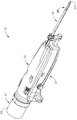
図1は、例示的な生検デバイス(10)を示し、この生検デバイスは、組織試料を患者から取得するために使用されることが可能である。生検デバイス(10)は、プローブアセンブリ(20)、ホルスタアセンブリ(30)、及び組織試料ホルダアセンブリ(40)を含む。プローブアセンブリ(20)は、遠位に突出する針(22)を含み、この針は、組織穿刺先端部(24)、及びこの先端部(24)へ近位に位置する横方向アパーチャ(26)を含む。チューブラカッター(図示せず)は、摺動可能に針(22)内に配置され、横方向アパーチャ(26)を通り突出している組織を切断するように動作可能である。切断された組織試料は、下記のように、組織試料ホルダアセンブリ(40)へカッターの内腔を近位に通過する。いくつかの変形において、プローブアセンブリ(20)は、制御モジュールと継合され、この制御モジュールは、プローブアセンブリ(20)への吸引、生理食塩水、及び/または大気圧の連通を提供するように動作可能である。
I. Exemplary Biopsy Device FIG. 1 shows an exemplary biopsy device (10) that can be used to obtain a tissue sample from a patient. The biopsy device (10) includes a probe assembly (20), a holster assembly (30), and a tissue sample holder assembly (40). The probe assembly (20) includes a distally projecting needle (22) that includes a tissue piercing tip (24) and a lateral aperture (26) located proximal to the tip (24). including. A tubular cutter (not shown) is slidably disposed within the needle (22) and is operable to cut tissue protruding through the transverse aperture (26). The cut tissue sample passes proximally through the lumen of the cutter to the tissue sample holder assembly (40) as described below. In some variations, the probe assembly (20) is coupled to a control module that provides suction, saline, and / or atmospheric pressure communication to the probe assembly (20). It is possible to operate.
ホルスタアセンブリ(30)は、カッターを駆動させるように動作可能である特徴、針(22)を遠位に組織中に発射させるように動作可能である特徴、及び針(22)の長手方向軸周囲で針(22)を回転させるように動作可能である特徴を有する。いくつかの変形において、ホルスタアセンブリ(30)は、ケーブルを介して制御モジュールと継合し、このケーブルは、電力及び/または他の電気信号をホルスタアセンブリ(30)へ提供するように動作可能である。加えて、または代替に、ホルスタアセンブリ(30)は、原動力を与えてプローブアセンブリ(20)のカッターを駆動させるために、加圧媒体(たとえば、空気、液圧流体など)を受容することができる。 The holster assembly (30) has features operable to drive the cutter, features operable to fire the needle (22) distally into tissue, and about the longitudinal axis of the needle (22). With a feature that is operable to rotate the needle (22). In some variations, the holster assembly (30) is coupled to the control module via a cable that is operable to provide power and / or other electrical signals to the holster assembly (30). is there. Additionally or alternatively, the holster assembly (30) can receive a pressurized medium (eg, air, hydraulic fluid, etc.) to provide a motive force to drive the cutter of the probe assembly (20). .
本発明の例において、プローブアセンブリ(20)及びホルスタアセンブリ(30)は、定位画像誘導生検処置における使用のために構成される。単なる例として、プローブアセンブリ(20)及びホルスタアセンブリ(30)は、「Biopsy System」と題する、2014年2月6日に公開された、米国公開第2014/0039343号の少なくとも一部の教示に従い構築され、動作可能であることができ、この開示は、本明細書に参照により援用される。代替に、プローブアセンブリ(20)及びホルスタアセンブリ(30)は、超音波画像誘導生検処置及び/またはMRI誘導生検処置における使用のために構成される(またはその他の処置において使用される)ことができる。さらに単なる例として、プローブアセンブリ(20)及びホルスタアセンブリ(30)は、「Biopsy Device with Slide−In Probe」と題する、2013年6月13日に公開された、米国公開第2013/0150751号の教示の少なくともいくつかに従い構築され、動作可能であることができ、この開示は、本明細書に参照により援用される。代替に、プローブアセンブリ(20)及びホルスタアセンブリ(30)は、いずれかの他の適切な方式において構築され、動作可能であることができる。 In the present example, the probe assembly (20) and holster assembly (30) are configured for use in a stereotactic image guided biopsy procedure. By way of example only, the probe assembly (20) and holster assembly (30) are constructed in accordance with the teachings of at least a portion of US Publication No. 2014/0039343, published February 6, 2014, entitled “Biopsy System”. The disclosure of which is hereby incorporated by reference. Alternatively, the probe assembly (20) and holster assembly (30) may be configured (or used in other procedures) for use in ultrasound image guided biopsy procedures and / or MRI guided biopsy procedures. Can do. By way of further example only, the probe assembly (20) and holster assembly (30) are taught in US Publication No. 2013/0150751, published 13 June 2013, entitled “Biopsy Device with Slide-In Probe”. Can be constructed and operated in accordance with at least some of the disclosures of which are hereby incorporated by reference. Alternatively, probe assembly (20) and holster assembly (30) can be constructed and operable in any other suitable manner.
上記のように、組織試料ホルダアセンブリ(40)は、横方向アパーチャ(26)を通り突出する組織からカッターによって切断される組織試料を受容するように構成される。図2に示されるように、この例の組織試料ホルダアセンブリ(40)は、円筒形外側カバー(42)を含み、この円筒形外側カバーは、プローブアセンブリ(20)と取り外し可能に継合する。回転自在部材(44)は、カバー(42)内に回転自在に置かれる。回転自在部材(44)は、ストリップ受容チャンバ(46)及びプラグチャンバ(48)の角度のある間隔で置かれたアレイを画定し、チャンバ(46、48)が合わせてアニュラー配置にあるようにする。回転自在部材(44)は、プローブアセンブリ(20)に関して回転自在であり、カッターに関してチャンバ(46、48)を選択的に連動させる。いくつかの変形において、ホルスタアセンブリ(30)内の駆動構成要素は、回転自在部材(44)の回転を駆動させる。いくつかの他の変形において、操作者が組織試料ホルダアセンブリ(40)のある部分を手動で把持することによって、回転自在部材(44)を手動で駆動させる。 As described above, the tissue sample holder assembly (40) is configured to receive a tissue sample that is cut by a cutter from tissue protruding through the transverse aperture (26). As shown in FIG. 2, the tissue sample holder assembly (40) of this example includes a cylindrical outer cover (42), which is removably joined with the probe assembly (20). The rotatable member (44) is rotatably placed in the cover (42). The rotatable member (44) defines an angularly spaced array of strip receiving chambers (46) and plug chambers (48) so that the chambers (46, 48) are in an annular configuration together. . The rotatable member (44) is rotatable with respect to the probe assembly (20) and selectively interlocks the chambers (46, 48) with respect to the cutter. In some variations, drive components in the holster assembly (30) drive the rotation of the rotatable member (44). In some other variations, the rotatable member (44) is manually driven by an operator manually grasping a portion of the tissue sample holder assembly (40).
また図2に示されるように、組織試料ホルダアセンブリ(40)は、1組の組織試料トレイ(100)をさらに含む。各組織試料トレイ(100)は、1セットの遠位に突出する組織試料ストリップ(110)を含む。各組織試料ストリップ(110)は、回転自在部材(44)の対応するストリップ受容チャンバ(46)中への取り外し可能な挿入のために構成される。各組織試料ストリップ(110)は、底面(114)によって接合される1セットのストリップ側壁部(112)を含む。ストリップ側壁部(112)及び底面(114)は、協働して組織受容チャンバ(120)を画定し、各組織試料ストリップ(110)が対応する組織試料を受容するように構成されるようにする。底面(114)は、複数の開口部(116)を画定し、これらの開口部は、そこを通る組織試料の連通を妨げながら、そこを通る吸引及び流体の連通を提供するような寸法に作られる。吸引がストリップ受容チャンバ(46)を通り伝えられ、組織受容チャンバ(120)に開口部(116)を介して到達することができることを理解するであろう。また、本発明の例の各組織試料ストリップ(110)は、遠位開口部(122)を含む。遠位開口部(122)は、切断された組織試料がそこを通過し、この組織試料が組織受容チャンバ(120)中に蓄積することを可能にするような寸法に作られ、この中に蓄積することを可能にするように構成される。 As also shown in FIG. 2, the tissue sample holder assembly (40) further includes a set of tissue sample trays (100). Each tissue sample tray (100) includes a set of distally projecting tissue sample strips (110). Each tissue sample strip (110) is configured for removable insertion of a rotatable member (44) into a corresponding strip receiving chamber (46). Each tissue sample strip (110) includes a set of strip sidewalls (112) joined by a bottom surface (114). The strip sidewall (112) and bottom surface (114) cooperate to define a tissue receiving chamber (120) such that each tissue sample strip (110) is configured to receive a corresponding tissue sample. . The bottom surface (114) defines a plurality of openings (116) that are sized to provide aspiration and fluid communication therethrough while preventing communication of the tissue sample therethrough. It is done. It will be appreciated that aspiration can be transmitted through the strip receiving chamber (46) and reach the tissue receiving chamber (120) via the opening (116). Each tissue sample strip (110) of the present example also includes a distal opening (122). The distal opening (122) is sized and allows the cut tissue sample to pass therethrough and accumulate in the tissue receiving chamber (120). Configured to allow you to.
図3から4に最もよく示されるように、各組織試料トレイ(100)は、近位に突出するプルタブ(130)をさらに備え、このプルタブは、タブ開口部(132)を画定する。プルタブ(130)は、操作者による組織試料トレイ(100)の把持を容易にするように構成される。また組織試料トレイ(100)は、1セットの近位パネル(140)を含む。本発明の例において、2つの組織試料ストリップ(110)は、1セットのパネル(140)の対応するパネル(140)に関して遠位に突出する。プルタブ(130)は、中央に置かれたパネル(140)から近位に突出する。リビングヒンジ(142)は、パネル(140)を合わせて可撓に接合する。リビングヒンジ(142)は、図3に示される弓形構成と、図4に示される平らな構成との間で組織試料トレイ(100)の移行を可能にする。弓形構成において、組織試料トレイ(100)は、回転自在部材(44)に装入するように構成される。平らな構成において、組織試料トレイ(100)は、以下により詳細に記載するように、容器(200)に装入するように構成される。 As best shown in FIGS. 3-4, each tissue sample tray (100) further comprises a proximally protruding pull tab (130), which defines a tab opening (132). The pull tab (130) is configured to facilitate grasping of the tissue sample tray (100) by an operator. The tissue sample tray (100) also includes a set of proximal panels (140). In the present example, two tissue sample strips (110) project distally with respect to corresponding panels (140) of a set of panels (140). The pull tab (130) projects proximally from the centrally located panel (140). The living hinge (142) is joined to the panel (140) flexibly. The living hinge (142) allows the transition of the tissue sample tray (100) between the arcuate configuration shown in FIG. 3 and the flat configuration shown in FIG. In the arcuate configuration, the tissue sample tray (100) is configured to be loaded into the rotatable member (44). In the flat configuration, the tissue sample tray (100) is configured to load into the container (200), as described in more detail below.
上記のように、回転自在部材(44)は、プローブアセンブリ(20)に関して回転自在であり、カッターに関してストリップ受容チャンバ(46)を選択的に連動させることにより、カッターに関して組織試料ストリップ(110)の組織受容チャンバ(120)を選択的に連動させる。また回転自在部材(44)は、カッターに関してプラグ受容チャンバ(48)を連動させるように動作可能である。回転自在部材(44)がカッターに関してプラグ受容チャンバ(48)を連動させるように角度のある位置に置かれるときに、プラグ(50)は、プラグ受容チャンバ(48)から取り外され、カッター及び針アセンブリ(22)を通して生検部位マーカーアプライヤー機器(またはいくつかの他の種類の機器)の挿入を可能にすることにより、横方向アパーチャ(26)を介して生検部位へのアクセス経路を提供することができる。その他の方法により、生検デバイス(10)の動作中にプラグ(50)をプラグ受容チャンバ(48)内に残すことにより、プラグ受容チャンバ(48)をシールすることができる。 As described above, the rotatable member (44) is rotatable with respect to the probe assembly (20) and selectively interlocking the strip receiving chamber (46) with respect to the cutter, thereby allowing the tissue sample strip (110) with respect to the cutter. The tissue receiving chamber (120) is selectively interlocked. The rotatable member (44) is also operable to interlock the plug receiving chamber (48) with respect to the cutter. When the rotatable member (44) is placed in an angular position to interlock the plug receiving chamber (48) with respect to the cutter, the plug (50) is removed from the plug receiving chamber (48) and the cutter and needle assembly is removed. Provide access path to biopsy site via lateral aperture (26) by allowing insertion of biopsy site marker applier device (or some other type of device) through (22) be able to. Other methods can seal the plug receiving chamber (48) by leaving the plug (50) in the plug receiving chamber (48) during operation of the biopsy device (10).
単なる例として、組織試料ホルダ(40)は、「Biopsy System」と題する、2014年2月6日に公開され、その開示が本明細書に参照により援用される、米国公開第2014/0039343号、及び/または「Biopsy Device」と題する、2014年9月18日に公開され、その開示が本明細書に参照により援用される、米国公開第2014/0275999号の教示の少なくともいくつかに従って構築され、動作可能であることができる。 By way of example only, a tissue sample holder (40) is published on Feb. 6, 2014, entitled "Biopsy System", the disclosure of which is incorporated herein by reference, US Publication No. 2014/0039343, And / or constructed in accordance with at least some of the teachings of U.S. Publication No. 2014/0275999, published September 18, 2014, entitled “Biopsy Device”, the disclosure of which is incorporated herein by reference, Can be operational.
II.組織試料トレイを支持する例示的な容器
上記のように、組織試料トレイ(100)は、組織試料トレイ(100)が図3に示される弓形構成と、図4に示される平らな構成との間で容易に移行することができるように可撓である。この可撓性は、操作者が当面の必要性に基づき組織試料トレイ(100)の構成を選択的に変更することを可能にするために有益であることができるが、この可撓性は、組織試料トレイ(100)を取り扱う方法に基づき組織試料ストリップ(110)の位置決め及び配置を維持するために、構造上の支持を組織試料トレイ(100)へ提供する必要性も与え得る。
II. Exemplary Container Supporting Tissue Sample Tray As noted above, the tissue sample tray (100) is between the arcuate configuration shown in FIG. 3 and the flat configuration shown in FIG. It is flexible so that it can be easily transferred. This flexibility can be beneficial to allow an operator to selectively change the configuration of the tissue sample tray (100) based on immediate needs, but this flexibility is There may also be a need to provide structural support to the tissue sample tray (100) to maintain the positioning and placement of the tissue sample strip (110) based on how the tissue sample tray (100) is handled.
加えて、ストリップ側壁部(112)及び底面(114)によって提供される「U」字形は、操作者が組織試料を各組織受容チャンバ(120)から(すなわち、側壁部(112)間に画定される開口部を介して)容易に引き抜くことを可能にすることができるが、特に組織試料トレイ(100)が図4に示される平らな構成にあるときに、各組織受容チャンバ(120)の一時的な封入を提供し、組織試料をそれぞれの組織受容チャンバ(120)中に完全に包含することが望ましい可能性がある。 In addition, the “U” shape provided by the strip sidewall (112) and bottom surface (114) allows the operator to define a tissue sample from each tissue receiving chamber (120) (ie, between the sidewalls (112). Can be easily withdrawn (through the opening), but in particular when the tissue sample tray (100) is in the flat configuration shown in FIG. It may be desirable to provide a general encapsulation and to completely include the tissue sample in each tissue receiving chamber (120).
単なる例として、組織試料がX線撮影マシンなどの撮像マシン内に置かれているときに、それぞれの組織受容チャンバ(120)内で組織試料を完全に包含する各組織受容チャンバ(120)の封入と同様に、上述の追加の構造上の支持を組織試料トレイ(100)へ提供することが望ましい可能性がある。同様に、組織試料が固定流体(たとえば、ホルマリン)中に包含されるときに、それぞれの組織受容チャンバ(120)内に組織試料を完全に包含する各組織受容チャンバ(120)の封入と同様に、上述の追加の構造上の支持を組織試料トレイ(100)へ提供することが望ましい可能性がある。 By way of example only, when a tissue sample is placed in an imaging machine, such as an x-ray machine, the encapsulation of each tissue receiving chamber (120) that completely contains the tissue sample within the respective tissue receiving chamber (120). Similarly, it may be desirable to provide the additional structural support described above to the tissue sample tray (100). Similarly, when a tissue sample is contained in a stationary fluid (eg, formalin), as well as the encapsulation of each tissue receiving chamber (120) that completely contains the tissue sample within the respective tissue receiving chamber (120). It may be desirable to provide the additional structural support described above to the tissue sample tray (100).
図5から7は、例示的な容器(200)を示し、この容器は、それぞれの組織受容チャンバ(120)内で組織試料を完全に包含する各組織受容チャンバ(120)の封入と同様に、構造上の支持を組織試料トレイ(100)へ提供するように動作可能である。この例の容器(200)は、複数のトレイ受容部(212)を画定する本体(210)を含む。より詳細に下記に説明するように、容器(200)は、その中で組織試料トレイ(100)を摺動可能に受容し、組織試料トレイ(100)の少なくとも一部を支持して、封入するように一般的に構成される。またより詳細に以下に説明するように、本発明の例の容器(200)は、組織試料トレイ(100)が上述の平らな構成において対応して支持されるように、一般的に剛性で平らな構成にある。容器(200)が一般的に剛性であるように本明細書に記載されているが、いくつかの例において、容器(200)の様々な構成要素が撓み、またはその他の方法により動き、容器(200)により支持されたままで弓形構成への組織試料トレイ(100)の移行を支持するように構成されることが可能であることを理解するであろう。容器(200)の可撓性構成要素の適切な例は、より詳細に以下に説明する。 FIGS. 5-7 illustrate an exemplary container (200), which, like the encapsulation of each tissue receiving chamber (120) that completely contains a tissue sample within the respective tissue receiving chamber (120), Operatable to provide structural support to the tissue sample tray (100). The container (200) of this example includes a body (210) that defines a plurality of tray receptacles (212). As will be described in more detail below, the container (200) slidably receives a tissue sample tray (100) therein and supports and encloses at least a portion of the tissue sample tray (100). Generally configured as follows. As will also be described in more detail below, the example container (200) of the present invention is generally rigid and flat so that the tissue sample tray (100) is correspondingly supported in the flat configuration described above. It is in a proper configuration. Although described herein such that the container (200) is generally rigid, in some instances, various components of the container (200) are deflected or otherwise moved to cause the container ( It will be appreciated that it can be configured to support the transition of the tissue sample tray (100) to the arcuate configuration while being supported by the Suitable examples of flexible components of the container (200) are described in more detail below.
本発明の例の本体(210)は、3つの別々であるが一体化して連結されたトレイ受容部(212)を含む。一般にトレイ受容部(212)は、組織試料トレイ(100)の一部を受容し、組織受容トレイ(100)の一部を支持して、封入するように構成される。特に、またより詳細に以下に説明するように、各トレイ受容部(212)は、組織試料トレイ(100)の1組の組織試料ストリップ(110)を受容するように構成される。各トレイ受容部(212)は、遠位端部(214)、近位端部(218)、1組の側壁部(222)、中央壁部(224)、上面(226)、及び底面(230)を備える。より詳細に以下に記載されるように、遠位端部(214)、近位端部(218)、側壁部(222)、中央壁部(224)、上面(226)、及び底面(230)は、すべて合わせて1組のトレイチャンバ(234)を画定する。 The example body (210) of the present invention includes three separate but integrated tray receivers (212). In general, the tray receiver (212) is configured to receive a portion of the tissue sample tray (100), support and enclose a portion of the tissue receiver tray (100). In particular, and as described in more detail below, each tray receiver (212) is configured to receive a set of tissue sample strips (110) of a tissue sample tray (100). Each tray receiver (212) includes a distal end (214), a proximal end (218), a set of side walls (222), a central wall (224), a top surface (226), and a bottom surface (230). ). The distal end (214), proximal end (218), sidewall (222), central wall (224), top surface (226), and bottom surface (230), as described in more detail below. All together define a set of tray chambers (234).
図5に最もよく示されるように、各トレイ受容部(212)の各遠位端部(214)は、遠位端部(214)が本体(210)にわたり横方向に延在する単一の遠位端部(214)を画定するように、対応して隣接する遠位端部(214)と一体化する。本発明の例の遠位端部(214)が一体化して連結されるように示されるが、他の例において、遠位端部(214)が特定の点で合わせて固着される別々の構成要素であることが可能であることを理解するであろう。それにもかかわらず、各遠位端部(214)は、複数のベント開口部(216)を含む。より詳細に以下に記載されるように、ベント開口部(216)は、流体が各遠位端部(214)を通り、トレイチャンバ(234)に流入し、これらのトレイチャンバから流出することを可能にするように構成される。 As best shown in FIG. 5, each distal end (214) of each tray receiver (212) is a single end with the distal end (214) extending laterally across the body (210). Correspondingly integral with the adjacent distal end (214) to define the distal end (214). While the distal end (214) of the example of the present invention is shown as being integrally connected, in other examples, separate configurations where the distal end (214) is secured together at a particular point. It will be understood that it can be an element. Nevertheless, each distal end (214) includes a plurality of vent openings (216). As described in more detail below, the vent openings (216) allow fluid to flow through each distal end (214) into the tray chambers (234) and out of these tray chambers. Configured to allow.
側壁部(222)、中央壁部(224)、上面(226)、及び底面(230)のすべては、遠位端部(214)から近位端部(218)へ近位に延在する。一般的に近位端部(218)は、1組のトレイ開口部(220)を画定する。一般的に、トレイ開口部(220)は、トレイチャンバ(234)に対して開口する。したがって、各トレイ開口部(220)が組織試料トレイ(100)の対応する組織試料ストリップ(110)を受容し、各組織試料ストリップ(110)の少なくとも一部をトレイチャンバ(234)内で受容することを可能にするように構成されることを理解するであろう。 The sidewall (222), central wall (224), top surface (226), and bottom surface (230) all extend proximally from the distal end (214) to the proximal end (218). The proximal end (218) generally defines a set of tray openings (220). Generally, the tray opening (220) opens to the tray chamber (234). Thus, each tray opening (220) receives a corresponding tissue sample strip (110) of the tissue sample tray (100) and receives at least a portion of each tissue sample strip (110) within the tray chamber (234). It will be understood that it is configured to allow that.
遠位端部(214)と近位端部(218)との間で、各上面(226)及び底面(230)は、複数のベント開口部(228、232)を画定する。各ベント開口部(228、232)は、長手方向に細長い構成に一般的に設定される。しかしながら、他の例において、いずれかの他の適切な構成を使用することが可能であることを理解するであろう。たとえば、いくつかの例において、ベント開口部(228、232)は、遠位端部(214)と関連するベント開口部(216)(たとえば、複数の楕円形または円形開口部)の形態を取ることができる。当然、本明細書の教示を考慮して当業者に明らかであるように、いずれかの他の適切な形状を使用することができる。 Between the distal end (214) and the proximal end (218), each top surface (226) and bottom surface (230) defines a plurality of vent openings (228, 232). Each vent opening (228, 232) is generally set to a longitudinally elongated configuration. However, it will be appreciated that in other examples any other suitable configuration may be used. For example, in some examples, vent openings (228, 232) take the form of vent openings (216) (eg, multiple oval or circular openings) associated with distal end (214). be able to. Of course, any other suitable shape can be used, as will be apparent to those skilled in the art in view of the teachings herein.
本発明の例のベント開口部(228、232)は、容器(200)の外面と、各トレイ受容部(212)の各トレイチャンバ(234)との間で連通するように各々が構成される。図7に最もよく示されるように、各ベント開口部(228、232)は、中央壁部(224)に直接隣接し、単一のベント開口部(228、232)が中央壁部(224)の存在にもかかわらずトレイチャンバ(234)の両方と連通するように構成されるようにする。この構成によりベント開口部(228、232)が機能性を最大にしながらより少ない空間を一般的に占めることが可能であることを理解するであろう。当然、他の例において、ベント開口部(228、232)は、単一のベント開口部(228、232)が単一のトレイチャンバ(234)のみと連通するように、配向されることが可能である。しかしながら、この構成の例において、本発明の例に示される数を上回る、追加のベント開口部(228、232)が本発明の例のベント開口部(228、232)と等しいベントを提供するために必要とされる可能性があることを理解するであろう。 The vent openings (228, 232) of the example of the present invention are each configured to communicate between the outer surface of the container (200) and each tray chamber (234) of each tray receiving portion (212). . As best shown in FIG. 7, each vent opening (228, 232) is directly adjacent to the central wall (224), and a single vent opening (228, 232) is the central wall (224). Despite being present, it is configured to communicate with both tray chambers (234). It will be appreciated that this configuration generally allows the vent openings (228, 232) to occupy less space while maximizing functionality. Of course, in other examples, the vent openings (228, 232) can be oriented such that a single vent opening (228, 232) communicates with only a single tray chamber (234). It is. However, in this example configuration, additional vent openings (228, 232), which exceed the number shown in the example of the present invention, provide vents equal to the vent openings (228, 232) of the example of the present invention. You will understand that it may be needed.
図6に戻り、各トレイ受容部(212)の側壁部(222)及び中央壁部(224)を合わせて、各トレイチャンバ(234)の横方向の延伸を画定する。特に、各側壁部(222)は、各組織試料トレイ(100)のストリップ側壁部(112)の形状と対応して一般的に鈍角(垂直の代替に)である。中央壁部(224)は、各側壁部(112)間に配置されることにより、各トレイ受容部(212)あたり2つの別個のトレイチャンバ(234)を画定する。互いの間にある一定の特異的な関係を有するものとして、側壁部(222)及び中央壁部(224)を本発明の例に示すが、これらの関係が組織試料トレイ(100)の組織試料ストリップ(110)の大きさ及び形状によって一般的に規定されることを理解するであろう。したがって、他の例において、側壁部(222)と中央壁部(224)との間のこれらの関係が異なる大きさ及び形状に作られた組織試料ストリップ(110)を含むトレイ(100)を収容するように所望に応じて変更されることが可能であることを理解するであろう。 Returning to FIG. 6, the side walls (222) and central wall (224) of each tray receiver (212) are combined to define the lateral extension of each tray chamber (234). In particular, each sidewall (222) is generally obtuse (in the alternative to a vertical) corresponding to the shape of the strip sidewall (112) of each tissue sample tray (100). A central wall (224) is positioned between each side wall (112) to define two separate tray chambers (234) for each tray receiver (212). The side wall (222) and the central wall (224) are shown in the example of the present invention as having a certain specific relationship between each other, and these relationships are the tissue sample of the tissue sample tray (100). It will be understood that it is generally defined by the size and shape of the strip (110). Thus, in another example, a tray (100) containing tissue sample strips (110) sized and shaped with different relationships between the side wall (222) and the central wall (224). It will be understood that it can be varied as desired.
上述のように、各トレイ受容部(212)は、隣接する遠位端部(214)と一体化している各遠位端部(214)によって接合される。加えて、本発明の例において各トレイ受容部(212)は、側壁部(222)によって隣接するトレイ受容部(212)にも連結される。特に、図6に最もよく見られるように、各側壁部(222)は、隣接するトレイ受容部(212)の別の側壁部(222)に隣接し、隣接する側壁部(222)に一体化して連結される。側壁部(222)間のこの一体化した連結は、組織試料トレイ(100)の少なくとも一部が各トレイ受容部(212)内に配置されるときに、追加の剛性を容器(200)へ与え、組織試料トレイ(100)を支持する。本発明の例の側壁部(222)を一体化して連結するように示すが、他の例において、側壁部(222)が本明細書の教示を考慮して当業者に明らかであるようにいずれかの他の適切な方式で互いに連結されることが可能であることを理解するであろう。 As described above, each tray receiver (212) is joined by each distal end (214) that is integral with an adjacent distal end (214). In addition, in the example of the present invention, each tray receiving portion (212) is connected to an adjacent tray receiving portion (212) by a side wall portion (222). In particular, as best seen in FIG. 6, each side wall (222) is adjacent to and integrated with another side wall (222) of an adjacent tray receiver (212). Connected. This integral connection between the side walls (222) provides additional rigidity to the container (200) when at least a portion of the tissue sample tray (100) is disposed within each tray receiver (212). Supporting the tissue sample tray (100). While the example sidewalls (222) of the present invention are shown as being joined together, in other examples, the sidewalls (222) are either as apparent to those skilled in the art in view of the teachings herein. It will be understood that they can be coupled together in any other suitable manner.
さらに容器(200)は、タブ(240)を備える。本発明の例のタブ(240)は、容器(200)の把持を可能にし、容器(200)のラベル付けを可能にするように構成される。特に、タブ(240)は、本体(210)の近位端部(218)から近位に延在する。本発明の例のタブ(240)が近位端部(218)の全長にわたり横方向に延在するように示されるが、他の例において、タブ(240)が近位端部(218)の一部のみに対して横方向に延在することが可能であることを理解するであろう。同様に、いくつかの例において、タブ(240)は、本体(210)の他の位置上に置かれることが可能である。たとえば、さらに他の例において、タブ(240)は、遠位端部(214)または側壁部(222)と関連することが可能である。当然、本明細書の教示を考慮して当業者に明らかであるように、タブ(240)のいずれかの他の適切な位置を使用することが可能である。 The container (200) further comprises a tab (240). The example tab (240) of the present invention is configured to allow grasping of the container (200) and to allow labeling of the container (200). In particular, tab (240) extends proximally from the proximal end (218) of body (210). While the example tab (240) of the present invention is shown extending laterally over the entire length of the proximal end (218), in other examples, the tab (240) of the proximal end (218) is shown. It will be understood that it is possible to extend laterally for only a portion. Similarly, in some examples, the tab (240) can be placed on other locations of the body (210). For example, in yet another example, tab (240) can be associated with distal end (214) or sidewall (222). Of course, any other suitable location of tab (240) can be used, as will be apparent to those skilled in the art in view of the teachings herein.
本発明の例のタブ(240)は、タブ(240)の上向きに面する表面の中心に配置されるラベル部(242)を含む。ラベル部(242)は、その中にラベルを受容するように構成される。より詳細に以下に記載されるように、生検取得及び試料解析処置の様々な時点で、容器(200)にラベル付けすることが望ましい可能性がある。このようなラベル付けは、処置全体を通して組織試料の追跡を促進するために望ましい可能性がある。 The example tab (240) of the present invention includes a label portion (242) disposed in the center of the upwardly facing surface of the tab (240). The label portion (242) is configured to receive a label therein. As described in more detail below, it may be desirable to label the container (200) at various times during biopsy acquisition and sample analysis procedures. Such labeling may be desirable to facilitate tracking of the tissue sample throughout the procedure.
本発明の例において、ラベル部(242)は、タブ(240)の上面より下にわずかなくぼみを作られる。その結果、本発明の例において、ラベルがラベル部(242)に接着すると、タブ(240)の上面と概ね同じ高さにあるように、ラベル部(242)がラベルを受容するように構成されることを理解するであろう。ラベル部(242)が本発明の例において一般的にくぼみを作られているが、他の例において、ラベル部(242)が異なって構成されることが可能であることを理解するであろう。たとえば、いくつかの例において、ラベルがラベル部(242)を適用するよりもむしろ直接ラベル部(242)上に印刷される、または書き込まれることができるように、ラベル部(242)は、塗面であることが可能である。 In the present example, the label (242) is slightly indented below the top surface of the tab (240). As a result, in the example of the present invention, the label portion (242) is configured to receive the label such that when the label is adhered to the label portion (242), the label portion (242) is substantially level with the top surface of the tab (240). You will understand that. It will be appreciated that although the label portion (242) is generally recessed in the examples of the present invention, in other examples the label portion (242) can be configured differently. . For example, in some examples, the label portion (242) can be painted so that the label can be printed or written directly on the label portion (242) rather than applying the label portion (242). It can be a surface.
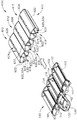
図8から12に示されるのは、組織試料トレイ(100)を受容する容器(200)の例示的な使用である。特に、図8に見られるように、組織試料トレイ(100)は、最初に容器(200)の外側で開始する。生検処置において、トレイが生検デバイス(10)から試料を受容し、組織試料ホルダアセンブリ(40)の回転自在部材(44)から取り外された時点に、組織試料トレイ(100)のこの最初の位置が対応することができることを理解するであろう。したがって、本明細書に記載される処置を使用して、組織取得後の検体X線撮影のために組織試料トレイ(100)を調製した後に、さらなる解析のために病理への組織試料トレイ(100)の後の輸送を伴うことができることを理解するであろう。 Shown in FIGS. 8-12 is an exemplary use of a container (200) for receiving a tissue sample tray (100). In particular, as seen in FIG. 8, the tissue sample tray (100) initially begins outside the container (200). In the biopsy procedure, this first of the tissue sample tray (100) is received when the tray receives the sample from the biopsy device (10) and is removed from the rotatable member (44) of the tissue sample holder assembly (40). It will be understood that the positions can correspond. Thus, after preparing a tissue sample tray (100) for specimen radiography after tissue acquisition using the procedures described herein, the tissue sample tray (100) to pathology for further analysis. It will be understood that subsequent transport) may be involved.
組織試料トレイ(100)を図8に示されるように容器(200)に隣接して置くと、組織試料トレイ(100)を図9に示される位置内の容器中に挿入することができる。組織試料トレイ(100)を容器(200)中に挿入するために、組織試料トレイ(100)の各組織試料ストリップ(110)は、各トレイ受容部(212)の対応するトレイチャンバ(234)と整列される。つぎに組織試料トレイ(100)を移動させ、各組織試料ストリップ(110)を、対応するトレイチャンバ(234)内に挿入する。 When the tissue sample tray (100) is placed adjacent to the container (200) as shown in FIG. 8, the tissue sample tray (100) can be inserted into the container in the position shown in FIG. In order to insert the tissue sample tray (100) into the container (200), each tissue sample strip (110) of the tissue sample tray (100) is associated with a corresponding tray chamber (234) of each tray receiver (212). Aligned. The tissue sample tray (100) is then moved and each tissue sample strip (110) is inserted into the corresponding tray chamber (234).
図10に最もよく示されるように、組織試料トレイ(100)の各組織試料ストリップ(110)を各トレイ受容部(212)の各トレイチャンバ(234)内に挿入すると、各組織試料ストリップ(110)をほぼ完全に各トレイチャンバ(234)内に配置する。しかしながら、各組織試料ストリップ(110)の各組織受容チャンバ(120)は、容器(200)の外面とベント開口部(216、228、232)を介して連通したままである。特に、遠位端部(214)と関連するベント開口部(216)は、組織受容チャンバ(120)と遠位開口部(122)を介して連通する。同様に、上面(226)と関連するベント開口部(228)は、組織受容チャンバ(120)と直接連通し、底面(232)と関連するベント開口部(234)は、組織受容チャンバ(120)と開口部(116)を介して底面(114)中で連通する。 As best shown in FIG. 10, when each tissue sample strip (110) of the tissue sample tray (100) is inserted into each tray chamber (234) of each tray receiver (212), each tissue sample strip (110) is shown. ) Almost completely in each tray chamber (234). However, each tissue receiving chamber (120) of each tissue sample strip (110) remains in communication with the outer surface of the container (200) via vent openings (216, 228, 232). In particular, the vent opening (216) associated with the distal end (214) communicates with the tissue receiving chamber (120) via the distal opening (122). Similarly, the vent opening (228) associated with the top surface (226) is in direct communication with the tissue receiving chamber (120), and the vent opening (234) associated with the bottom surface (232) is the tissue receiving chamber (120). And in the bottom surface (114) through the opening (116).
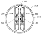
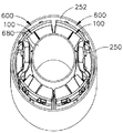
組織試料トレイ(100)の各組織試料ストリップ(110)を各トレイ受容部(212)の対応するトレイチャンバ(234)中に挿入すると、組織試料トレイ(100)に加えて容器(200)は、検体X線撮影が望まれる場合、検体X線撮影を受けることができる。単なる例として、「Biopsy Sample Container」と題する、2017年6月30日に出願され、その開示が参照により本明細書に援用される、米国第15/638,740号の教示のうちの少なくともいくつかに従い、適切な検体X線撮影処置を実施することができる。検体X線撮影が完了すると、または検体X線撮影を実施しない場合に、図11に示されるように、組織試料トレイ(100)に加えて容器(200)をカップ(250)中に挿入することができる。カップ(250)を使用して、組織試料を、たとえば、病理研究室などへ輸送することができる。いくつかの例において、容器(200)を固定流体(252)(たとえば、ホルマリン)中に直ちに浸漬させるように、固定流体(252)によってカップ(250)を事前に充填することができる。いくつかの他の例において、容器(200)をカップ(250)中に最初に置いた後、固定流体(252)をカップ(250)に導入することができる。いずれかの事例において、固定流体(252)が容器(200)の内面中にベント開口部(216、228、232)を介して直ちに通過することができることを理解するであろう。それにより、固定流体(252)は、容器(200)中のトレイチャンバ(234)内に包含される組織試料に容易に到達して、これらの組織試料を浸漬させることができる。容器(200)及び固定流体(252)がカップ(250)中にありながら、つぎに、操作者は、カップ蓋(254)をカップ(250)に固着させることにより、容器(200)及び固定流体(252)をカップ(250)中でシールすることができる。容器(200)及び固定流体(252)をカップ(250)中にシールした後に、つぎにさらに処理するために、カップ(250)を別の位置に輸送し、保管のために取っておく、またはその他の方法により取り扱うことができる。 When each tissue sample strip (110) of the tissue sample tray (100) is inserted into the corresponding tray chamber (234) of each tray receiver (212), in addition to the tissue sample tray (100), the container (200) If sample X-ray imaging is desired, sample X-ray imaging can be received. By way of example only, at least some of the teachings of US 15 / 638,740, filed June 30, 2017, entitled “Biopsy Sample Container”, the disclosure of which is incorporated herein by reference. Accordingly, an appropriate specimen X-ray imaging procedure can be performed. When the specimen X-ray imaging is completed or when the specimen X-ray imaging is not performed, the container (200) is inserted into the cup (250) in addition to the tissue sample tray (100) as shown in FIG. Can do. The cup (250) can be used to transport a tissue sample, such as to a pathology laboratory. In some examples, the cup (250) can be pre-filled with the stationary fluid (252) so that the container (200) is immediately immersed in the stationary fluid (252) (eg, formalin). In some other examples, the stationary fluid (252) can be introduced into the cup (250) after the container (200) is first placed in the cup (250). It will be appreciated that in either case, the stationary fluid (252) can immediately pass through the vent openings (216, 228, 232) into the inner surface of the container (200). Thereby, the fixation fluid (252) can easily reach the tissue samples contained in the tray chamber (234) in the container (200) and immerse these tissue samples. While the container (200) and the fixed fluid (252) are in the cup (250), the operator then secures the cup lid (254) to the cup (250), thereby allowing the container (200) and the fixed fluid to be fixed. (252) can be sealed in the cup (250). After the container (200) and stationary fluid (252) are sealed in the cup (250), the cup (250) is transported to another location for further processing and set aside for storage, or It can be handled by other methods.
図12に最もよく示されるように、いくつかの例において、カップ(250)が複数の容器(200)を受容することができることを理解するであろう。特に、本発明の例において、容器(200)の横方向の幅は、カップ(250)の内径未満の所定の寸法にほぼ対応する。このため、容器(200)の横方向の幅が1回に2つまでの容器(200)をカップ(250)内に配置することができるように構成されることを理解するであろう。 It will be appreciated that, in some examples, the cup (250) can receive multiple containers (200), as best shown in FIG. In particular, in the present example, the lateral width of the container (200) substantially corresponds to a predetermined dimension that is less than the inner diameter of the cup (250). Thus, it will be understood that the lateral width of the container (200) is configured so that up to two containers (200) can be placed in the cup (250) at a time.
いずれかの段階で、上述の処置中に、ラベルをタブ(240)のラベル部(242)に添着することができることを理解するであろう。たとえば、いくつかの例において、組織試料トレイ(100)の容器(200)中への挿入前に、ラベルをラベル部(242)上に付着させる、またはその他の方法により提供することができる。他の例において、組織試料トレイ(100)の容器(200)中への挿入後、ラベルをラベル部(242)上に付着させる、またはその他の方法により提供することができる。当然、さらに他の例において、上述の処置中のいずれかの他の適切な時点で、ラベルをラベル部(242)上に付着させる、またはその他の方法により提供することができる。 It will be appreciated that at any stage, a label can be attached to the label portion (242) of the tab (240) during the procedure described above. For example, in some examples, the label can be deposited on the label portion (242) or otherwise provided prior to insertion of the tissue sample tray (100) into the container (200). In other examples, after insertion of the tissue sample tray (100) into the container (200), the label can be deposited on the label portion (242) or otherwise provided. Of course, in still other examples, the label may be deposited on the label portion (242) or otherwise provided at any other suitable time during the procedure described above.
III.組織試料トレイを支持するための例示的な代替の容器
図13は、上述の容器(200)と実質的に類似する例示的な代替の容器(300)を示す。たとえば、容器(200)と同様に、容器(300)は、それぞれの組織受容チャンバ(120)中に組織試料を完全に包含する各組織受容チャンバ(120)の封入と同様に、構造上の支持を組織試料トレイ(100)へ提供するように動作可能である。しかしながら、上述の容器(200)と異なり、本発明の例の容器(300)は、組織試料トレイ(100)を摺動可能に受容することに加えて、ドロップイン方式で組織試料トレイ(100)を受容するように一般的に構成される。この例の容器(300)は、複数のトレイ受容部(312)を画定する本体(310)を含む。より詳細に以下に説明するように、容器(300)は、その中で組織試料トレイ(100)を摺動可能に受容し、組織試料トレイ(100)の少なくとも一部を支持して、封入するように一般的に構成される。またより詳細に以下に説明するように、本発明の例の容器(300)は、組織試料トレイ(100)が上述の平らな構成において対応して支持されるように、一般的に剛性で平らな構成にある。
III. Exemplary Alternative Container for Supporting Tissue Sample Tray FIG. 13 shows an exemplary alternative container (300) that is substantially similar to the container (200) described above. For example, similar to the container (200), the container (300) provides structural support similar to the encapsulation of each tissue receiving chamber (120) that completely encloses a tissue sample in the respective tissue receiving chamber (120). To the tissue sample tray (100). However, unlike the container (200) described above, the example container (300) of the present invention has a tissue sample tray (100) in a drop-in manner in addition to slidably receiving the tissue sample tray (100). Generally configured to accept. The container (300) of this example includes a body (310) that defines a plurality of tray receptacles (312). As described in more detail below, container (300) slidably receives tissue sample tray (100) therein and supports and encloses at least a portion of tissue sample tray (100). Generally configured as follows. Also as described in more detail below, the example container (300) of the present invention is generally rigid and flat so that the tissue sample tray (100) is correspondingly supported in the flat configuration described above. It is in a proper configuration.
本発明の例の本体(310)は、3つの別々であるが一体化して連結されたトレイ受容部(312)を含む。一般にトレイ受容部(312)は、組織試料トレイ(100)の一部を受容し、組織受容トレイ(100)の一部を支持して、封入するように構成される。特に、またより詳細に以下に説明するように、各トレイ受容部(312)は、組織試料トレイ(100)の1組の組織試料ストリップ(110)を受容するように構成される。各トレイ受容部(312)は、遠位端部(314)、近位端部(318)、1組の側壁部(322)、中央壁部(324)、上面(326)、及び底面(330)を備える。より詳細に以下に記載されるように、遠位端部(314)、近位端部(318)、側壁部(322)、中央壁部(324)、上面(326)、及び底面(330)は、すべて合わせて1組のトレイチャンバ(334)を画定する。 The example body (310) of the present invention includes three separate but integrated tray receivers (312). Generally, the tray receiver (312) is configured to receive a portion of the tissue sample tray (100), support and enclose a portion of the tissue receiving tray (100). In particular, and as described in more detail below, each tray receiver (312) is configured to receive a set of tissue sample strips (110) of a tissue sample tray (100). Each tray receiver (312) includes a distal end (314), a proximal end (318), a set of sidewalls (322), a central wall (324), a top surface (326), and a bottom surface (330). ). As described in more detail below, the distal end (314), the proximal end (318), the sidewall (322), the central wall (324), the top surface (326), and the bottom surface (330) All together define a set of tray chambers (334).
各トレイ受容部(312)の各遠位端部(314)は、遠位端部(314)が本体(310)にわたり横方向に延在する単一の遠位端部(314)を画定するように、対応して隣接する遠位端部(314)と一体化する。本発明の例の遠位端部(314)が一体化して連結されるように示されるが、他の例において、遠位端部(314)が特定の点で合わせて固着される別々の構成要素であることが可能であることを理解するであろう。それにもかかわらず、各遠位端部(314)は、複数のベント開口部(316)を含む。上述のベント開口部(216)と同様に、本発明の例のベント開口部(316)は、流体が各遠位端部(314)を通り、トレイチャンバ(334)に流入し、これらのトレイチャンバから流出することを可能にするように構成される。 Each distal end (314) of each tray receiver (312) defines a single distal end (314) with the distal end (314) extending laterally across the body (310). As such, it is correspondingly integral with the adjacent distal end (314). While the distal end (314) of the example of the present invention is shown as being integrally connected, in other examples, separate configurations where the distal end (314) is secured together at a particular point. It will be understood that it can be an element. Nevertheless, each distal end (314) includes a plurality of vent openings (316). Similar to the vent opening (216) described above, the vent opening (316) of the example of the present invention allows fluid to flow through each distal end (314) and into the tray chamber (334) as these trays. It is configured to allow outflow from the chamber.
側壁部(322)、中央壁部(324)、上面(326)、及び底面(330)のすべては、遠位端部(314)から近位端部(318)へ近位に延在する。一般的に近位端部(318)は、1組のトレイ開口部(320)を画定する。一般的に、トレイ開口部(320)は、トレイチャンバ(334)に対して開口する。したがって、各トレイ開口部(320)が組織試料トレイ(100)の対応する組織試料ストリップ(110)を受容し、各組織試料ストリップ(110)の少なくとも一部をトレイチャンバ(334)内で受容することを可能にするように構成されることを理解するであろう。 The sidewall (322), central wall (324), top surface (326), and bottom surface (330) all extend proximally from the distal end (314) to the proximal end (318). The proximal end (318) generally defines a set of tray openings (320). Generally, the tray opening (320) opens to the tray chamber (334). Thus, each tray opening (320) receives a corresponding tissue sample strip (110) of the tissue sample tray (100) and receives at least a portion of each tissue sample strip (110) within the tray chamber (334). It will be understood that it is configured to allow that.
遠位端部(314)と近位端部(318)との間で、各上面(326)及び底面(330)は、複数のベント開口部(328、332)を画定する。各ベント開口部(328、332)は、長手方向に細長い構成に一般的に設定される。しかしながら、他の例において、いずれかの他の適切な構成を使用することが可能であることを理解するであろう。たとえば、いくつかの例において、ベント開口部(328、332)は、遠位端部(314)と関連するベント開口部(316)(たとえば、複数の楕円形または円形開口部)の形態を取ることができる。当然、本明細書の教示を考慮して当業者に明らかであるように、いずれかの他の適切な形状を使用することができる。 Between the distal end (314) and the proximal end (318), each top surface (326) and bottom surface (330) defines a plurality of vent openings (328, 332). Each vent opening (328, 332) is generally set to a longitudinally elongated configuration. However, it will be appreciated that in other examples any other suitable configuration may be used. For example, in some examples, vent openings (328, 332) take the form of vent openings (316) (eg, multiple elliptical or circular openings) associated with distal end (314). be able to. Of course, any other suitable shape can be used, as will be apparent to those skilled in the art in view of the teachings herein.
本発明の例のベント開口部(328、332)は、容器(300)の外面と、各トレイ受容部(312)の各トレイチャンバ(334)との間で連通するように各々が構成される。単一のベント開口部(328、332)が中央壁部(324)の存在にもかかわらずトレイチャンバ(334)の両方と連通するように構成されるように、各ベント開口部(328、332)は、中央壁部(324)に直接隣接する。 The vent openings (328, 332) of the example of the present invention are each configured to communicate between the outer surface of the container (300) and each tray chamber (334) of each tray receiver (312). . Each vent opening (328, 332) is configured such that a single vent opening (328, 332) is in communication with both tray chambers (334) despite the presence of the central wall (324). ) Is directly adjacent to the central wall (324).
各トレイ受容部(312)の側壁部(322)及び中央壁部(324)は、各トレイチャンバ(334)の横方向の延伸を合わせて画定する。特に、各側壁部(322)は、各組織試料トレイ(100)のストリップ側壁部(112)の形状と対応して一般的に鈍角(垂直の代替に)である。中央壁部(324)は、各側壁部(112)間に配置されることにより、各トレイ受容部(312)あたり2つの別個のトレイチャンバ(334)を画定する。互いの間にある一定の特異的な関係を有するものとして、側壁部(322)及び中央壁部(324)を本発明の例に示すが、これらの関係が組織試料トレイ(100)の組織試料ストリップ(110)の大きさ及び形状によって一般的に規定されることを理解するであろう。したがって、他の例において、側壁部(322)と中央壁部(324)との間のこれらの関係が異なる大きさ及び形状に作られた組織試料ストリップ(110)を含むトレイ(100)を収容するように所望に応じて変更されることが可能であることを理解するであろう。 The side wall portion (322) and the central wall portion (324) of each tray receiving portion (312) define the lateral extension of each tray chamber (334) together. In particular, each sidewall (322) is generally obtuse (in the alternative to a vertical) corresponding to the shape of the strip sidewall (112) of each tissue sample tray (100). A central wall (324) is disposed between each side wall (112) to define two separate tray chambers (334) for each tray receiver (312). The side wall (322) and the central wall (324) are shown in the example of the present invention as having a certain specific relationship between each other, and these relationships are shown in the tissue sample tray (100) tissue sample. It will be understood that it is generally defined by the size and shape of the strip (110). Thus, in another example, a tray (100) containing tissue sample strips (110) made in different sizes and shapes in which the relationship between the sidewall (322) and the central wall (324) is different. It will be understood that it can be varied as desired.
上述のように、各トレイ受容部(312)は、隣接する遠位端部(314)と一体化している各遠位端部(314)によって接合される。加えて、本発明の例において各トレイ受容部(312)は、側壁部(322)によって隣接するトレイ受容部(312)にも連結される。各側壁部(322)は、隣接するトレイ受容部(312)の別の側壁部(322)に隣接し、隣接する側壁部(322)に一体化して連結される。側壁部(322)間のこの一体化した連結は、組織試料トレイ(100)の少なくとも一部が各トレイ受容部(312)内に配置されるときに、追加の剛性を容器(300)へ与え、組織試料トレイ(100)を支持する。 As described above, each tray receiver (312) is joined by each distal end (314) that is integral with an adjacent distal end (314). In addition, in the example of the present invention, each tray receiving part (312) is connected to an adjacent tray receiving part (312) by a side wall part (322). Each side wall portion (322) is adjacent to another side wall portion (322) of the adjacent tray receiving portion (312), and is integrally connected to the adjacent side wall portion (322). This integral connection between the side walls (322) provides additional rigidity to the container (300) when at least a portion of the tissue sample tray (100) is disposed within each tray receiver (312). Supporting the tissue sample tray (100).
容器(200)と異なり、本発明の例の容器(300)は、上述のタブ(240)に類似するタブを含むものとしては示されていない。しかしながら、示されないが、いくつかの例において、容器(300)が上述のタブ(240)に類似するタブを含むことが可能であることを理解するであろう。これらのような例において、このようなタブは、容器(300)の把持を可能にするように、また容器(300)のラベル付けを可能にするように構成されることが可能である。加えて、このようなタブは、上述のラベル部(242)に類似するラベル部を同様に含むことができる。このようなラベル部は、くぼみを作られることが可能であり、そのくぼみの中にラベルを受容するように構成される。 Unlike the container (200), the example container (300) of the present invention is not shown as including a tab similar to the tab (240) described above. However, although not shown, it will be appreciated that in some examples, the container (300) may include a tab similar to the tab (240) described above. In examples such as these, such tabs can be configured to allow grasping of the container (300) and to allow labeling of the container (300). In addition, such a tab can similarly include a label portion similar to the label portion (242) described above. Such a label portion can be made a recess and is configured to receive a label in the recess.
上述の容器(200)と異なり、本発明の例の容器(300)は、各トレイ受容部(312)の各上面(326)の少なくとも一部が本体(310)の残りから取り外し可能であるように構成される。特に、図13に見られるように、各上面(326)は、すべての上面(326)を本体(310)から離して枢動させ、本体(310)を開口することが可能であるように、互いと相互に連結される。この特徴は、枢動時に上面(326)によって画定される開口領域を通り摺動することによって、または降下することによって、組織試料トレイ(100)を容器(300)中に挿入することが可能であるような追加の機能性を提供するように構成される。 Unlike the container (200) described above, the example container (300) of the present invention is such that at least a portion of each upper surface (326) of each tray receiving portion (312) is removable from the rest of the body (310). Consists of. In particular, as seen in FIG. 13, each upper surface (326) can pivot all the upper surfaces (326) away from the body (310) and open the body (310), Interconnected with each other. This feature allows the tissue sample tray (100) to be inserted into the container (300) by sliding through the open area defined by the top surface (326) during pivoting or by lowering. Configured to provide some additional functionality.
示されないが、本発明の例において、リビングヒンジによって各上面(326)を本体(310)へ固着させ、このリビングヒンジが各上面の近位端部を各トレイ受容部(312)の近位端部(318)に連結させることを理解するであろう。リビングヒンジ特徴を本発明の例に関して記載するが、他の例において、いずれかの他の適切なヒンジ特徴を使用することができることを理解するであろう。さらに他の例において、リビングヒンジを完全に省くことができ、各上面(326)は、本体(310)から完全に取り外すことができる。加えて、本発明の例が取り外し可能な上面(326)のみを含むように示されるが、他の例において、側壁部(322)及び中央壁部(324)の部分も上面(326)によって取り外し可能であることができることを理解するであろう。 Although not shown, in the example of the present invention, each living upper surface (326) is secured to the body (310) by a living hinge that attaches the proximal end of each upper surface to the proximal end of each tray receiver (312). It will be understood that it is connected to part (318). Although living hinge features are described with respect to examples of the present invention, it will be understood that in other examples, any other suitable hinge feature may be used. In yet another example, the living hinge can be omitted completely and each top surface (326) can be completely removed from the body (310). In addition, although examples of the present invention are shown to include only a removable top surface (326), in other examples, portions of the sidewall (322) and central wall (324) are also removed by the top surface (326). It will be understood that it can be possible.
図14は、上述の容器(300)と実質的に類似する例示的な代替の容器(400)を示す。たとえば、容器(300)と同様に、容器(400)は、それぞれの組織受容チャンバ(120)中に組織試料を完全に包含する各組織受容チャンバ(120)の封入と同様に、構造上の支持を組織試料トレイ(100)へ提供するように動作可能である。この例の容器(400)は、複数のトレイ受容部(412)を画定する本体(410)を含む。より詳細に以下に説明するように、容器(400)は、その中で組織試料トレイ(100)を摺動可能に受容し、組織試料トレイ(100)の少なくとも一部を支持して、封入するように一般的に構成される。 FIG. 14 shows an exemplary alternative container (400) that is substantially similar to the container (300) described above. For example, similar to the container (300), the container (400) may provide structural support, similar to the encapsulation of each tissue receiving chamber (120) that completely contains a tissue sample in the respective tissue receiving chamber (120). To the tissue sample tray (100). The container (400) of this example includes a body (410) that defines a plurality of tray receptacles (412). As described in more detail below, container (400) slidably receives tissue sample tray (100) therein and supports and encloses at least a portion of tissue sample tray (100). Generally configured as follows.
本発明の例の本体(410)は、3つの別々であるが一体化して連結されたトレイ受容部(412)を含む。一般にトレイ受容部(412)は、組織試料トレイ(100)の一部を受容し、組織受容トレイ(100)の一部を支持して、封入するように構成される。特に、またより詳細に以下に説明するように、各トレイ受容部(412)は、組織試料トレイ(100)の1組の組織試料ストリップ(110)を受容するように構成される。各トレイ受容部(412)は、遠位端部(414)、近位端部(418)、1組の側壁部(422)、中央壁部(424)、上面(426)、及び底面(430)を備える。より詳細に以下に記載されるように、遠位端部(414)、近位端部(418)、側壁部(422)、中央壁部(424)、上面(426)、及び底面(430)は、すべて合わせて1組のトレイチャンバ(434)を画定する。 The example body (410) of the present invention includes three separate but integrated tray receivers (412). Generally, the tray receiving portion (412) is configured to receive a portion of the tissue sample tray (100), support and enclose a portion of the tissue receiving tray (100). In particular, and as described in more detail below, each tray receiver (412) is configured to receive a set of tissue sample strips (110) of a tissue sample tray (100). Each tray receiver (412) includes a distal end (414), a proximal end (418), a set of sidewalls (422), a central wall (424), a top surface (426), and a bottom surface (430). ). The distal end (414), proximal end (418), sidewall (422), central wall (424), top surface (426), and bottom surface (430), as described in more detail below. All together define a set of tray chambers (434).
各トレイ受容部(412)の各遠位端部(414)は、遠位端部(414)が本体(410)にわたり横方向に延在する単一の遠位端部(414)を画定するように、対応して隣接する遠位端部(414)と一体化する。本発明の例の遠位端部(414)が一体化して連結されるように示されるが、他の例において、遠位端部(414)が特定の点で合わせて固着される別々の構成要素であることが可能であることを理解するであろう。それにもかかわらず、各遠位端部(414)は、複数のベント開口部(416)を含む。上述のベント開口部(316)と同様に、本発明の例のベント開口部(416)は、流体が各遠位端部(414)を通り、トレイチャンバ(434)に流入し、これらのトレイチャンバから流出することを可能にするように構成される。 Each distal end (414) of each tray receiver (412) defines a single distal end (414) with the distal end (414) extending laterally across the body (410). As such, it is correspondingly integral with the adjacent distal end (414). Although the distal end (414) of the example of the present invention is shown as being joined together, in other examples, separate configurations where the distal end (414) is secured together at a particular point. It will be understood that it can be an element. Nevertheless, each distal end (414) includes a plurality of vent openings (416). Similar to the vent opening (316) described above, the vent opening (416) of the example of the present invention allows fluid to flow through each distal end (414) and into the tray chamber (434), where these trays It is configured to allow outflow from the chamber.
側壁部(422)、中央壁部(424)、上面(426)、及び底面(430)のすべては、遠位端部(414)から近位端部(418)へ近位に延在する。一般的に近位端部(418)は、1組のトレイ開口部(420)を画定する。一般的に、トレイ開口部(420)は、トレイチャンバ(434)に対して開口する。したがって、各トレイ開口部(420)が組織試料トレイ(100)の対応する組織試料ストリップ(110)を受容し、各組織試料ストリップ(110)の少なくとも一部をトレイチャンバ(434)内で受容することを可能にするように構成されることを理解するであろう。 The sidewall (422), central wall (424), top surface (426), and bottom surface (430) all extend proximally from the distal end (414) to the proximal end (418). Generally, the proximal end (418) defines a set of tray openings (420). Generally, the tray opening (420) opens to the tray chamber (434). Thus, each tray opening (420) receives a corresponding tissue sample strip (110) of the tissue sample tray (100) and receives at least a portion of each tissue sample strip (110) within the tray chamber (434). It will be understood that it is configured to allow that.
遠位端部(414)と近位端部(418)との間で、各上面(426)及び底面(430)は、複数のベント開口部(428、432)を画定する。各ベント開口部(428、432)は、長手方向に細長い構成に一般的に設定される。しかしながら、他の例において、いずれかの他の適切な構成を使用することが可能であることを理解するであろう。たとえば、いくつかの例において、ベント開口部(428、432)は、遠位端部(414)と関連するベント開口部(416)(たとえば、複数の楕円形または円形開口部)の形態を取ることができる。当然、本明細書の教示を考慮して当業者に明らかであるように、いずれかの他の適切な形状を使用することができる。 Between the distal end (414) and the proximal end (418), each top surface (426) and bottom surface (430) defines a plurality of vent openings (428, 432). Each vent opening (428, 432) is generally set to a longitudinally elongated configuration. However, it will be appreciated that in other examples any other suitable configuration may be used. For example, in some examples, vent openings (428, 432) take the form of vent openings (416) (eg, multiple elliptical or circular openings) associated with distal end (414). be able to. Of course, any other suitable shape can be used, as will be apparent to those skilled in the art in view of the teachings herein.
本発明の例のベント開口部(428、432)は、容器(400)の外面と、各トレイ受容部(412)の各トレイチャンバ(434)との間で連通するように各々が構成される。単一のベント開口部(428、432)が中央壁部(424)の存在にもかかわらずトレイチャンバ(434)の両方と連通するように構成されるように、各ベント開口部(428、432)は、中央壁部(424)に直接隣接する。 The vent openings (428, 432) of the present example are each configured to communicate between the outer surface of the container (400) and each tray chamber (434) of each tray receiver (412). . Each vent opening (428, 432) is configured such that a single vent opening (428, 432) is in communication with both tray chambers (434) despite the presence of the central wall (424). ) Directly adjacent to the central wall (424).
各トレイ受容部(412)の側壁部(422)及び中央壁部(424)を合わせて、各トレイチャンバ(434)の横方向の延伸を画定する。特に、各側壁部(422)は、各組織試料トレイ(100)のストリップ側壁部(112)の形状と対応して一般的に鈍角(垂直の代替に)である。中央壁部(424)は、各側壁部(112)間に配置されることにより、各トレイ受容部(412)あたり2つの別個のトレイチャンバ(434)を画定する。互いの間にある一定の特異的な関係を有するものとして、側壁部(422)及び中央壁部(424)を本発明の例に示すが、これらの関係が組織試料トレイ(100)の組織試料ストリップ(110)の大きさ及び形状によって一般的に規定されることを理解するであろう。したがって、他の例において、側壁部(422)と中央壁部(424)との間のこれらの関係が異なる大きさ及び形状に作られた組織試料ストリップ(110)を含むトレイ(100)を収容ように所望に応じて変更されることが可能であることを理解するであろう。 The side wall portion (422) and the central wall portion (424) of each tray receiving portion (412) together define the lateral extension of each tray chamber (434). In particular, each sidewall (422) is generally obtuse (in a vertical alternative) corresponding to the shape of the strip sidewall (112) of each tissue sample tray (100). A central wall (424) is positioned between each side wall (112) to define two separate tray chambers (434) for each tray receiver (412). The side wall (422) and the central wall (424) are shown in the example of the present invention as having a certain specific relationship between each other, and these relationships are the tissue sample of the tissue sample tray (100). It will be understood that it is generally defined by the size and shape of the strip (110). Thus, in another example, a tray (100) containing tissue sample strips (110) sized and shaped with different relationships between the side wall (422) and the central wall (424). It will be understood that it can be modified as desired.
上述のように、各トレイ受容部(412)は、隣接する遠位端部(414)と一体化している各遠位端部(414)によって接合される。加えて、本発明の例において各トレイ受容部(412)は、側壁部(422)によって隣接するトレイ受容部(412)にも連結される。各側壁部(422)は、隣接するトレイ受容部(412)の別の側壁部(422)に隣接し、隣接する側壁部(422)に一体化して連結される。側壁部(422)間のこの一体化した連結は、組織試料トレイ(100)の少なくとも一部が各トレイ受容部(412)内に配置されるときに、追加の剛性を容器(400)へ与え、組織試料トレイ(100)を支持する。 As described above, each tray receiver (412) is joined by each distal end (414) that is integral with an adjacent distal end (414). In addition, in the example of the present invention, each tray receiving portion (412) is connected to an adjacent tray receiving portion (412) by a side wall portion (422). Each side wall portion (422) is adjacent to another side wall portion (422) of the adjacent tray receiving portion (412), and is integrally connected to the adjacent side wall portion (422). This integral connection between the side wall portions (422) provides additional rigidity to the container (400) when at least a portion of the tissue sample tray (100) is disposed within each tray receiving portion (412). Supporting the tissue sample tray (100).
容器(200)と異なり、本発明の例の容器(400)は、上述のタブ(240)に類似するタブを含むように示されない。しかしながら、示されないが、いくつかの例において、容器(400)が上述のタブ(240)に類似するタブを含むことが可能であることを理解するであろう。これらのような例において、このようなタブは、容器(400)の把持を可能にするように、また容器(400)のラベル付けを可能にするように構成されることが可能である。加えて、このようなタブは、上述のラベル部(242)に類似するラベル部を同様に含むことができる。このようなラベル部は、くぼみを作られることが可能であり、そのくぼみの中にラベルを受容するように構成される。 Unlike the container (200), the example container (400) of the present invention is not shown to include a tab similar to the tab (240) described above. However, although not shown, it will be appreciated that in some examples, the container (400) may include a tab similar to the tab (240) described above. In examples such as these, such tabs can be configured to allow grasping of the container (400) and to allow labeling of the container (400). In addition, such a tab can similarly include a label portion similar to the label portion (242) described above. Such a label portion can be made a recess and is configured to receive a label in the recess.
上述の容器(200)と異なるが、容器(300)に類似する、本発明の例の容器(400)は、各トレイ受容部(412)の各上面(426)の少なくとも一部が本体(410)の残りから取り外し可能であるように構成される。特に、図14に見られるように、各上面(426)は、本体(410)から離れて枢動し、本体(410)を開口するように構成される。しかしながら、上述の容器(300)の上面(326)と異なり、本発明の例の上面(426)は、相互に連結されない。代替に、各上面(426)は、他の上面(426)に関して独立して枢動可能である。したがって、各トレイ受容部(412)は、他のトレイ受容部(412)に関して独立して開口されるように構成される。この特徴は、上面(426)が枢動する時に上面(426)によって画定される開口領域を通り摺動することによって、または降下することによって、組織試料トレイ(100)を容器(400)中に挿入することが可能であるような追加の機能性を提供するように構成される。 In the container (400) of the example of the present invention, which is different from the container (200) described above, but is similar to the container (300), at least a part of each upper surface (426) of each tray receiving portion (412) is a main body (410). ) Configured to be removable from the rest. In particular, as seen in FIG. 14, each upper surface (426) is configured to pivot away from the body (410) and open the body (410). However, unlike the upper surface (326) of the container (300) described above, the upper surface (426) of the example of the present invention is not interconnected. Alternatively, each top surface (426) can pivot independently with respect to the other top surface (426). Thus, each tray receiver (412) is configured to be opened independently with respect to the other tray receiver (412). This feature is achieved by sliding the tissue sample tray (100) into the container (400) by sliding through or lowering the open area defined by the upper surface (426) as the upper surface (426) pivots. Configured to provide additional functionality such that it can be inserted.
示されないが、本発明の例において、リビングヒンジによって各上面(426)を本体(410)へ固着させ、このリビングヒンジが各上面の近位端部を各トレイ受容部(412)の近位端部(418)に連結させることを理解するであろう。リビングヒンジ特徴を本発明の例に関して記載するが、他の例において、いずれかの他の適切なヒンジ特徴を使用することができることを理解するであろう。さらに他の例において、リビングヒンジを完全に省くことができ、各上面(426)は、本体(410)から完全に取り外し可能であることができる。加えて、本発明の例が取り外し可能な上面(426)のみを含むように示されるが、他の例において、側壁部(422)及び中央壁部(424)の部分も上面(426)によって取り外し可能であることができることを理解するであろう。 Although not shown, in the example of the present invention, each living upper surface (426) is secured to the body (410) by a living hinge that attaches the proximal end of each upper surface to the proximal end of each tray receiving portion (412). It will be understood that it is connected to part (418). Although living hinge features are described with respect to examples of the present invention, it will be understood that in other examples, any other suitable hinge feature may be used. In yet another example, the living hinge can be omitted completely and each top surface (426) can be completely removable from the body (410). In addition, although examples of the present invention are shown to include only a removable top surface (426), in other examples, portions of the side wall (422) and central wall (424) are also removed by the top surface (426). It will be understood that it can be possible.
図15は、上述の容器(300、400)と実質的に類似する例示的な代替の容器(500)を示す。たとえば、容器(300、400)と同様に、容器(500)は、それぞれの組織受容チャンバ(120)中に組織試料を完全に包含する各組織受容チャンバ(120)の封入と同様に、構造上の支持を組織試料トレイ(100)へ提供するように動作可能である。この例の容器(500)は、複数のトレイ受容部(512)を画定する本体(510)を含む。より詳細に以下に記載されるように、容器(500)は、その中に組織試料トレイ(100)を摺動可能に受容し、組織試料トレイ(100)の少なくとも一部を支持して、封入するように一般的に構成される。 FIG. 15 shows an exemplary alternative container (500) that is substantially similar to the containers (300, 400) described above. For example, similar to the containers (300, 400), the containers (500) are structurally similar to the encapsulation of each tissue receiving chamber (120) that completely contains a tissue sample in the respective tissue receiving chamber (120). Is operable to provide support to the tissue sample tray (100). The container (500) of this example includes a body (510) that defines a plurality of tray receptacles (512). As described in more detail below, the container (500) slidably receives a tissue sample tray (100) therein and supports and encloses at least a portion of the tissue sample tray (100). Generally configured to do.
本発明の例の本体(510)は、3つの別々であるが一体化して連結されたトレイ受容部(512)を含む。一般にトレイ受容部(512)は、組織試料トレイ(100)の一部を受容し、組織受容トレイ(100)の一部を支持して、封入するように構成される。特に、またより詳細に以下に記載されるように、各トレイ受容部(512)は、組織試料トレイ(100)の1組の組織試料ストリップ(110)を受容するように構成される。各トレイ受容部(512)は、遠位端部(514)、近位端部(518)、1組の側壁部(522)、中央壁部(524)、上面(526)、及び底面(530)を備える。より詳細に以下に記載されるように、遠位端部(514)、近位端部(518)、側壁部(522)、中央壁部(524)、上面(526)、及び底面(530)は、すべて合わせて1組のトレイチャンバ(534)を画定する。 The example body (510) of the present invention includes three separate but integrally connected tray receivers (512). Generally, the tray receiving portion (512) is configured to receive a portion of the tissue sample tray (100), support a portion of the tissue receiving tray (100), and enclose it. In particular, and as described in more detail below, each tray receiver (512) is configured to receive a set of tissue sample strips (110) of a tissue sample tray (100). Each tray receiver (512) includes a distal end (514), a proximal end (518), a set of sidewalls (522), a central wall (524), a top surface (526), and a bottom surface (530). ). The distal end (514), proximal end (518), sidewall (522), central wall (524), top surface (526), and bottom surface (530), as described in more detail below. All together define a set of tray chambers (534).
各トレイ受容部(512)の各遠位端部(514)は、遠位端部(514)が本体(510)にわたり横方向に延在する単一の遠位端部(514)を画定するように、対応して隣接する遠位端部(514)と一体化する。一般的に本発明の例の遠位端部(514)が一体化して連結されるが、他の例において、遠位端部(514)が特定の点で合わせて固着される別々の構成要素であることが可能であることを理解するであろう。それにもかかわらず、各遠位端部(514)は、複数のベント開口部(516)を含む。上述のベント開口部(316)と同様に、本発明の例のベント開口部(516)は、流体が各遠位端部(514)を通り、トレイチャンバ(534)に流入し、これらのトレイチャンバから流出することを可能にするように構成される。 Each distal end (514) of each tray receiver (512) defines a single distal end (514) with the distal end (514) extending laterally across the body (510). As such, it is correspondingly integral with the adjacent distal end (514). In general, the distal end (514) of the example of the present invention is integrally connected, but in other examples, the separate components to which the distal end (514) is secured together at a particular point You will understand that it is possible. Nevertheless, each distal end (514) includes a plurality of vent openings (516). Similar to the vent openings (316) described above, the vent openings (516) of the example of the present invention allow fluid to flow through each distal end (514) and into the tray chamber (534), where these trays It is configured to allow outflow from the chamber.
側壁部(522)、中央壁部(524)、上面(526)、及び底面(530)のすべては、遠位端部(514)から近位端部(518)へ近位に延在する。一般的に近位端部(518)は、1組のトレイ開口部(520)を画定する。一般的に、トレイ開口部(520)は、トレイチャンバ(534)に対して開口する。したがって、各トレイ開口部(520)が組織試料トレイ(100)の対応する組織試料ストリップ(110)を受容し、各組織試料ストリップ(110)の少なくとも一部をトレイチャンバ(534)内で受容することを可能にするように構成されることを理解するであろう。 The sidewall (522), central wall (524), top surface (526), and bottom surface (530) all extend proximally from the distal end (514) to the proximal end (518). Generally the proximal end (518) defines a set of tray openings (520). Generally, the tray opening (520) opens to the tray chamber (534). Thus, each tray opening (520) receives a corresponding tissue sample strip (110) of the tissue sample tray (100) and receives at least a portion of each tissue sample strip (110) within the tray chamber (534). It will be understood that it is configured to allow that.
遠位端部(514)と近位端部(518)との間で、各上面(526)及び底面(530)は、複数のベント開口部(528、532)を画定する。各ベント開口部(528、532)は、長手方向に細長い構成に一般的に設定される。しかしながら、他の例において、いずれかの他の適切な構成を使用することが可能であることを理解するであろう。たとえば、いくつかの例において、ベント開口部(528、532)は、遠位端部(514)と関連するベント開口部(516)(たとえば、複数の楕円形または円形開口部)の形態を取ることができる。当然、本明細書の教示を考慮して当業者に明らかであるように、いずれかの他の適切な形状を使用することができる。 Between the distal end (514) and the proximal end (518), each top surface (526) and bottom surface (530) defines a plurality of vent openings (528, 532). Each vent opening (528, 532) is generally set to a longitudinally elongated configuration. However, it will be appreciated that in other examples any other suitable configuration may be used. For example, in some examples, vent openings (528, 532) take the form of a vent opening (516) (eg, a plurality of elliptical or circular openings) associated with distal end (514). be able to. Of course, any other suitable shape can be used, as will be apparent to those skilled in the art in view of the teachings herein.
本発明の例のベント開口部(528、532)は、容器(500)の外面と、各トレイ受容部(512)の各トレイチャンバ(534)との間で連通するように各々が構成される。単一のベント開口部(528、532)が中央壁部(524)の存在にもかかわらずトレイチャンバ(534)の両方と連通するように構成されるように、各ベント開口部(528、532)は、中央壁部(524)に直接隣接する。 The vent openings (528, 532) of the example of the present invention are each configured to communicate between the outer surface of the container (500) and each tray chamber (534) of each tray receiving portion (512). . Each vent opening (528, 532) is configured such that a single vent opening (528, 532) communicates with both of the tray chambers (534) despite the presence of the central wall (524). ) Is directly adjacent to the central wall (524).
各トレイ受容部(512)の側壁部(522)及び中央壁部(524)を合わせて、各トレイチャンバ(534)の横方向の延伸を画定する。特に、各側壁部(522)は、各組織試料トレイ(100)のストリップ側壁部(112)の形状と対応して一般的に鈍角(垂直の代替に)である。中央壁部(524)は、各側壁部(112)間に配置されることにより、各トレイ受容部(512)あたり2つの別個のトレイチャンバ(534)を画定する。互いの間にある一定の特異的な関係を有するものとして、側壁部(522)及び中央壁部(524)を本発明の例に示すが、これらの関係が組織試料トレイ(100)の組織試料ストリップ(110)の大きさ及び形状によって一般的に規定されることを理解するであろう。したがって、他の例において、側壁部(522)と中央壁部(524)との間のこれらの関係が異なる大きさ及び形状に作られた組織試料ストリップ(110)を含むトレイ(100)を収容するように所望に応じて変更されることが可能であることを理解するであろう。 The side walls (522) and the central wall (524) of each tray receiver (512) together define the lateral extension of each tray chamber (534). In particular, each sidewall (522) is generally obtuse (in a vertical alternative) corresponding to the shape of the strip sidewall (112) of each tissue sample tray (100). A central wall (524) is disposed between each side wall (112) to define two separate tray chambers (534) for each tray receiver (512). The side wall (522) and the central wall (524) are shown in the example of the present invention as having a certain specific relationship between each other, and these relationships are the tissue sample of the tissue sample tray (100). It will be understood that it is generally defined by the size and shape of the strip (110). Thus, in another example, a tray (100) containing tissue sample strips (110) sized and shaped with different relationships between the side wall (522) and the central wall (524). It will be understood that it can be varied as desired.
上述のように、各トレイ受容部(512)は、隣接する遠位端部(514)と一体化している各遠位端部(514)によって接合される。加えて、本発明の例において各トレイ受容部(512)は、側壁部(522)によって隣接するトレイ受容部(512)にも連結される。各側壁部(522)は、隣接するトレイ受容部(512)の別の側壁部(522)に隣接し、隣接する側壁部(522)に一体化して連結される。側壁部(522)間のこの一体化した連結は、組織試料トレイ(100)の少なくとも一部が各トレイ受容部(512)内に配置されるときに、追加の剛性を容器(500)へ与え、組織試料トレイ(100)を支持する。 As described above, each tray receiver (512) is joined by each distal end (514) that is integral with an adjacent distal end (514). In addition, in the example of the present invention, each tray receiving portion (512) is connected to an adjacent tray receiving portion (512) by a side wall portion (522). Each side wall portion (522) is adjacent to another side wall portion (522) of the adjacent tray receiving portion (512), and is integrally connected to the adjacent side wall portion (522). This integral connection between the side walls (522) provides additional rigidity to the container (500) when at least a portion of the tissue sample tray (100) is disposed within each tray receiver (512). Supporting the tissue sample tray (100).
容器(200)と異なり、本発明の例の容器(500)は、上述のタブ(240)に類似するタブを含むように示されない。しかしながら、示されないが、いくつかの例において、容器(500)が上述のタブ(240)に類似するタブを含むことが可能であることを理解するであろう。これらのような例において、このようなタブは、容器(500)の把持を可能にするように、また容器(500)のラベル付けを可能にするように構成されることが可能である。加えて、このようなタブは、上述のラベル部(242)に類似するラベル部を同様に含むことができる。このようなラベル部は、くぼみを作られることが可能であり、そのくぼみの中にラベルを受容するように構成される。 Unlike the container (200), the example container (500) of the present invention is not shown to include a tab similar to the tab (240) described above. However, although not shown, it will be appreciated that in some examples, the container (500) may include a tab similar to the tab (240) described above. In examples such as these, such tabs can be configured to allow grasping of the container (500) and to allow labeling of the container (500). In addition, such a tab can similarly include a label portion similar to the label portion (242) described above. Such a label portion can be made a recess and is configured to receive a label in the recess.
上述の容器(200)と異なるが、容器(300、400)に類似する、本発明の例の容器(400)は、各トレイ受容部(512)の各上面(526)の少なくとも一部が本体(410)の残りから取り外し可能であるように構成される。特に、図15に見られるように、各上面(526)は、本体(510)から離れて枢動し、本体(510)を開口させるように構成される。上述の容器(300)の上面(326)と同様に、本発明の例の上面(526)は、上面(526)が別個のユニットとして枢動可能であるようにそれぞれ相互に連結される。したがって、各トレイ受容部(512)は、他のトレイ受容部(512)に関して同時に開口するように構成される。この特徴は、上面(526)が枢動するときに、上面(526)によって画定される開口領域を通り摺動することによって、または降下することによって、組織試料トレイ(100)を容器(500)中に挿入することが可能であるような追加の機能性を提供するように構成される。 The container (400) of the example of the present invention, which is different from the container (200) described above but is similar to the container (300, 400), has at least a part of each upper surface (526) of each tray receiving portion (512) as a main body. (410) configured to be removable from the rest. In particular, as seen in FIG. 15, each upper surface (526) is configured to pivot away from the body (510) and open the body (510). Similar to the top surface (326) of the container (300) described above, the top surface (526) of the example of the present invention is each interconnected such that the top surface (526) is pivotable as a separate unit. Thus, each tray receiver (512) is configured to open simultaneously with respect to the other tray receiver (512). This feature allows the tissue sample tray (100) to be placed in the container (500) by sliding through or dropping through the open area defined by the top surface (526) as the top surface (526) pivots. Configured to provide additional functionality such that it can be inserted therein.
示されないが、本発明の例において、リビングヒンジによって、本体(510)に各上面(526)を固着し、このリビングヒンジが各上面(526)の側部を各トレイ受容部(512)の最も側方の側壁部(522)に連結することを理解するであろう。したがって、上述の容器(300、400)と異なり、本発明の例の容器(500)が異なる位置に配置されるヒンジ特徴を含むことを理解するであろう。リビングヒンジ特徴を本発明の例に関して記載するが、他の例において、いずれかの他の適切なヒンジ特徴を使用することができることを理解するであろう。さらに他の例において、リビングヒンジを完全に省くことができ、各上面(526)は、本体(510)から完全に取り外し可能であることができる。加えて、本発明の例が取り外し可能な上面(526)のみを含むように示されるが、他の例において、側壁部(522)及び中央壁部(524)の部分も上面(526)によって取り外し可能であることができることを理解するであろう。 Although not shown, in the example of the present invention, each upper surface (526) is secured to the main body (510) by a living hinge, and this living hinge attaches the side of each upper surface (526) to the most of each tray receiving portion (512). It will be appreciated that it connects to the side wall (522). Thus, it will be appreciated that unlike the containers (300, 400) described above, the example container (500) of the present invention includes hinge features that are located at different locations. Although living hinge features are described with respect to examples of the present invention, it will be understood that in other examples, any other suitable hinge feature may be used. In yet another example, the living hinge can be omitted completely and each top surface (526) can be completely removable from the body (510). In addition, although examples of the present invention are shown to include only a removable top surface (526), in other examples, portions of the side wall (522) and the central wall (524) are also removed by the top surface (526). It will be understood that it can be possible.
上述の容器(200、300、400)と異なり、本発明の例の容器(500)は、最も外側のトレイ受容部(512)の最も外側の側壁部(522)から横方向に延在するラベル付け部(560)をさらに備える。本発明の例のラベル付け部(560)は、1組の腕部(562)及びラベル部材(564)を備える。腕部(562)は、側壁部(522)から外方向に延在し、側壁部(522)とラベル部材(564)との間に間隙を提供する。本発明の例のラベル付け部(560)が腕部(562)を含むが、いくつかの例において、腕部(562)を完全に省くことができることを理解するであろう。これらのような例において、ラベル部材(564)を側壁部(522)に直接固着する。 Unlike the containers (200, 300, 400) described above, the example container (500) of the present invention is a label that extends laterally from the outermost side wall (522) of the outermost tray receiver (512). The attaching part (560) is further provided. The labeling portion (560) of the example of the present invention includes a pair of arm portions (562) and a label member (564). The arms (562) extend outwardly from the side wall (522) and provide a gap between the side wall (522) and the label member (564). It will be appreciated that although the example labeling portion (560) of the present invention includes an arm portion (562), in some instances the arm portion (562) can be omitted entirely. In these examples, the label member (564) is secured directly to the side wall (522).
ラベル部材(564)は、腕部(562)から外方向に延在する。示されないが、本発明の例において、腕部(562)が各腕部(562)間に延在するダボを含むことを理解するであろう。ダボにラベル部材(564)を回転自在に固着させ、ダボは、ラベル部材(564)が腕部(562)に関して回転するように構成されるように、各腕部(562)間に延在する。一般的にラベル部材(564)は、ラベル部材(564)が折り畳まれる、捻られる、曲げられる、またはその他の方法により様々な位置の間で移行するように構成されるような可撓性である。その結果、ラベル部材(564)が腕部周囲で回転することができるようなフラッグに類似して、容器(500)周囲で折り畳まれ、曲げられるように構成されることを理解するであろう。この特徴は、容器(500)を限られた空間内に配置する(たとえば、上述のカップ(250)内に配置するときなどの)様々な状況に対して、ラベル部材(564)の圧縮した位置への移行を可能にする。 The label member (564) extends outward from the arm portion (562). Although not shown, it will be understood that in the examples of the present invention, arms (562) include dowels extending between each arm (562). A label member (564) is rotatably secured to the dowel, and the dowel extends between each arm (562) such that the label member (564) is configured to rotate relative to the arm (562). . Generally, the label member (564) is flexible such that the label member (564) is configured to be folded, twisted, bent, or otherwise transitioned between various positions. . As a result, it will be appreciated that the label member (564) is configured to be folded and bent around the container (500), similar to a flag that can rotate around the arm. This feature can be attributed to the compressed position of the label member (564) for a variety of situations, such as when the container (500) is placed in a limited space (eg, when placed in the cup (250) described above). Enables the transition to
本発明の例のラベル部材(564)は、上部または下部の表面上にラベルを受容するように構成される。たとえば、ラベル部材(564)のいくつかの用途において、操作者は、生検及び組織解析処置中の様々な段階で、自己接着ラベルをラベル部材(564)上に配置することができる。本発明の例のラベル部材(564)が別々のラベルを受容することに関して説明されているが、他の例において、ラベルがラベル部材(564)上に直接書き込まれる、または印刷されることができることを理解するであろう。 The example label member (564) of the present invention is configured to receive a label on an upper or lower surface. For example, in some applications of label member (564), an operator can place a self-adhesive label on label member (564) at various stages during a biopsy and tissue analysis procedure. Although the example label member (564) of the present invention has been described with respect to receiving separate labels, in other examples, the label can be directly written or printed on the label member (564). Will understand.
IV.組織試料トレイを支持する例示的な折り畳み可能な容器
上記のように、いくつかの状況において、組織試料トレイ(100)を取り扱う方法に基づき組織試料ストリップ(110)の位置決め及び配置を維持するために、構造上の支持を組織試料トレイ(100)へ提供することが望ましい可能性がある。しかしながら、この構造上の支持が容器(200)に関して上述のように必ずしも性質上等方性である必要がないことを理解するであろう。単なる例として、単一平面沿いの組織試料トレイ(100)へ、または組織試料トレイ(100)の特定の部分に関して、上述の追加の構造上の支持を与えることが望ましい可能性がある。しかしながら、これらのような例において、組織試料を固定流体(たとえば、ホルマリン)中に含有するときに、各組織受容チャンバ(120)の封入を提供し、それぞれの組織受容チャンバ(120)内に組織試料を完全に包含することが依然として望ましい可能性があることを理解するであろう。
IV. Exemplary Foldable Container Supporting Tissue Sample Tray As noted above, in some situations, to maintain the positioning and placement of tissue sample strip (110) based on how to handle tissue sample tray (100) It may be desirable to provide structural support to the tissue sample tray (100). However, it will be understood that this structural support need not necessarily be isotropic in nature as described above with respect to the container (200). Merely by way of example, it may be desirable to provide the additional structural support described above to a tissue sample tray (100) along a single plane or with respect to a particular portion of the tissue sample tray (100). However, in examples such as these, when a tissue sample is contained in a fixation fluid (eg, formalin), an encapsulation of each tissue receiving chamber (120) is provided and the tissue within each tissue receiving chamber (120) It will be appreciated that complete inclusion of the sample may still be desirable.
図16及び17は、例示的な容器(600)を示し、この容器は、それぞれの組織受容チャンバ(120)内で組織試料を完全に包含する各組織受容チャンバ(120)の封入と同様に、構造上の支持を組織試料トレイ(100)へ提供するように動作可能である。しかしながら、上述の容器(200)と異なり、本発明の例の容器(600)は、より詳細に以下に記載されるように、様々な流体含有デバイス内に容器(600)を収容するように、一般的に少なくとも1本の軸にまたがり曲げられることが可能である。 FIGS. 16 and 17 show an exemplary container (600), which, like the encapsulation of each tissue receiving chamber (120) that completely contains a tissue sample within the respective tissue receiving chamber (120), Operatable to provide structural support to the tissue sample tray (100). However, unlike the container (200) described above, the example container (600) of the present invention is adapted to house the container (600) in various fluid containing devices, as described in more detail below. Generally it can be bent over at least one axis.
上述の容器(200)と同様に、この例の容器(600)は、複数のトレイ受容部(612)を画定する本体(610)を含む。より詳細に以下に記載されるように、容器(600)は、その中に組織試料トレイ(100)を摺動可能に受容し、組織試料トレイ(100)の少なくとも一部を支持して、封入するように一般的に構成される。より詳細に以下に記載されるように、本発明の例の容器(600)は、一般的に剛性であり、さらに各トレイ受容部(612)は、容器(600)が平らな構成から弓形構成へ移行するように構成されるように、隣接するトレイ受容部(612)に関して枢動可能である。 Similar to the container (200) described above, the container (600) of this example includes a body (610) that defines a plurality of tray receptacles (612). As described in more detail below, a container (600) slidably receives a tissue sample tray (100) therein and supports and encloses at least a portion of the tissue sample tray (100). Generally configured to do. As described in more detail below, the example container (600) of the present invention is generally rigid, and each tray receiver (612) is configured in an arcuate configuration from a flat configuration of the container (600). Can be pivoted with respect to an adjacent tray receiver (612).
本発明の例の本体(610)は、3つの別々であるが一体化して連結されたトレイ受容部(612)を含む。一般にトレイ受容部(612)は、組織試料トレイ(100)の一部を受容し、組織受容トレイ(100)の一部を支持して、封入するように構成される。特に、またより詳細に以下に記載されるように、各トレイ受容部(612)は、組織試料トレイ(100)の1組の組織試料ストリップ(110)を受容するように構成される。各トレイ受容部(612)は、遠位端部(614)、近位端部(618)、1組の側壁部(622)、中央壁部(624)、上面(626)、及び底面(630)を備える。より詳細に以下に記載されるように、遠位端部(614)、近位端部(618)、側壁部(622)、中央壁部(624)、上面(626)、及び底面(630)は、すべて合わせて1組のトレイチャンバ(634)を画定する。 The example body (610) of the present invention includes three separate but integrated tray receivers (612). Generally, the tray receiving portion (612) is configured to receive a portion of the tissue sample tray (100), support and enclose a portion of the tissue receiving tray (100). In particular, and as described in more detail below, each tray receiver (612) is configured to receive a set of tissue sample strips (110) of a tissue sample tray (100). Each tray receiver (612) includes a distal end (614), a proximal end (618), a set of sidewalls (622), a central wall (624), a top surface (626), and a bottom surface (630). ). The distal end (614), proximal end (618), sidewall (622), central wall (624), top surface (626), and bottom surface (630), as described in more detail below. All together define a set of tray chambers (634).
各トレイ受容部(612)の各遠位端部(614)は、遠位端部(614)が本体(610)にわたり横方向に延在するように相互に連結されるように、対応して隣接する遠位端部(614)と一体化し、さらにこれから分離する。特に、各遠位端部(614)は、別の隣接する遠位端部(614)の一部のみと一般的に相互に連結され、各遠位端部(614)間に間隙(670)を画定する。より詳細に以下に記載されるように、この構成は、遠位端部(614)が互いに関して撓むことを一般的に可能にすることにより、各トレイ受容部(612)の平らな構成から弓形構成への移行を可能にする。 Each distal end (614) of each tray receiver (612) is correspondingly coupled so that the distal end (614) extends laterally across the body (610). Integrates with and separates from the adjacent distal end (614). In particular, each distal end (614) is generally interconnected with only a portion of another adjacent distal end (614), with a gap (670) between each distal end (614). Is defined. As will be described in more detail below, this configuration results from the flat configuration of each tray receiver (612) by generally allowing the distal ends (614) to flex with respect to each other. Allows transition to arcuate configuration.
各遠位端部(614)は、複数のベント開口部(616)を含む。上述のベント開口部(216)と同様に、本発明の例のベント開口部(616)は、流体が各遠位端部(614)を通り、トレイチャンバ(634)に流入し、これらのトレイチャンバから流出することを可能にするように構成される。より詳細に以下に記載されるように、この構成は、トレイチャンバ(634)を固定流体(たとえば、ホルマリン)によって充填することを可能にすることにより、組織試料を固定流体中に浸す。 Each distal end (614) includes a plurality of vent openings (616). Similar to the vent opening (216) described above, the vent opening (616) of the example of the present invention allows fluid to flow through each distal end (614) and into the tray chamber (634) as these trays. It is configured to allow outflow from the chamber. As described in more detail below, this configuration immerses the tissue sample in the fixative fluid by allowing the tray chamber (634) to be filled with the fixative fluid (eg, formalin).
側壁部(622)、中央壁部(624)、上面(626)、及び底面(630)のすべては、遠位端部(614)から近位端部(618)へ近位に延在する。一般的に近位端部(618)は、1組のトレイ開口部(620)を画定する。一般的に、トレイ開口部(620)は、トレイチャンバ(634)に対して開口する。したがって、各トレイ開口部(620)が組織試料トレイ(100)の対応する組織試料ストリップ(110)を受容し、各組織試料ストリップ(110)の少なくとも一部をトレイチャンバ(634)内で受容することを可能にするように構成されることを理解するであろう。 The sidewall (622), central wall (624), top surface (626), and bottom surface (630) all extend proximally from the distal end (614) to the proximal end (618). Generally, the proximal end (618) defines a set of tray openings (620). Generally, the tray opening (620) opens to the tray chamber (634). Thus, each tray opening (620) receives a corresponding tissue sample strip (110) of the tissue sample tray (100) and receives at least a portion of each tissue sample strip (110) within the tray chamber (634). It will be understood that it is configured to allow that.
遠位端部(614)と近位端部(618)との間で、各上面(626)及び底面(630)は、複数のベント開口部(628、632)を画定する。各ベント開口部(628、632)は、長手方向に細長い構成に一般的に設定される。しかしながら、他の例において、いずれかの他の適切な構成を使用することが可能であることを理解するであろう。たとえば、いくつかの例において、ベント開口部(628、632)は、遠位端部(614)と関連するベント開口部(616)(たとえば、複数の楕円形または円形開口部)の形態を取ることができる。当然、本明細書の教示を考慮して当業者に明らかであるように、いずれかの他の適切な形状を使用することができる。 Between the distal end (614) and the proximal end (618), each top surface (626) and bottom surface (630) defines a plurality of vent openings (628, 632). Each vent opening (628, 632) is generally set to a longitudinally elongated configuration. However, it will be appreciated that in other examples any other suitable configuration may be used. For example, in some examples, vent openings (628, 632) take the form of vent openings (616) (eg, multiple oval or circular openings) associated with distal end (614). be able to. Of course, any other suitable shape can be used, as will be apparent to those skilled in the art in view of the teachings herein.
本発明の例のベント開口部(628、632)は、容器(600)の外面と、各トレイ受容部(612)の各トレイチャンバ(634)との間で連通するように各々が構成される。単一のベント開口部(628、632)が中央壁部(624)の存在にもかかわらずトレイチャンバ(634)の両方と連通するように構成されるように、各ベント開口部(628、632)は、中央壁部(624)に直接隣接する。 The vent openings (628, 632) of the example of the present invention are each configured to communicate between the outer surface of the container (600) and each tray chamber (634) of each tray receiving portion (612). . Each vent opening (628, 632) is configured such that a single vent opening (628, 632) communicates with both of the tray chambers (634) despite the presence of the central wall (624). ) Directly adjacent to the central wall (624).
各トレイ受容部(612)の側壁部(622)及び中央壁部(624)を合わせて、各トレイチャンバ(634)の横方向の延伸を画定する。特に、各側壁部(622)は、各組織試料トレイ(100)のストリップ側壁部(112)の形状と対応して一般的に鈍角(垂直の代替に)である。中央壁部(624)は、各側壁部(112)間に配置されることにより、各トレイ受容部(612)あたり2つの別個のトレイチャンバ(634)を画定する。互いの間にある一定の特異的な関係を有するものとして、側壁部(622)及び中央壁部(624)を本発明の例に示すが、これらの関係が組織試料トレイ(100)の組織試料ストリップ(110)の大きさ及び形状によって一般的に規定されることを理解するであろう。したがって、他の例において、側壁部(622)と中央壁部(624)との間のこれらの関係が異なる大きさ及び形状に作られた組織試料ストリップ(110)を含むトレイ(100)を収容するように所望に応じて変更されることが可能であることを理解するであろう。 The side wall portion (622) and the central wall portion (624) of each tray receiving portion (612) together define the lateral extension of each tray chamber (634). In particular, each sidewall (622) is generally obtuse (in the alternative to a vertical) corresponding to the shape of the strip sidewall (112) of each tissue sample tray (100). A central wall (624) is positioned between each side wall (112) to define two separate tray chambers (634) for each tray receiver (612). The side wall (622) and the central wall (624) are shown in the example of the present invention as having a certain specific relationship between each other, and these relationships are shown in the tissue sample tray (100) tissue sample. It will be understood that it is generally defined by the size and shape of the strip (110). Thus, in another example, a tray (100) containing tissue sample strips (110) sized and shaped with different relationships between the side wall (622) and the central wall (624). It will be understood that it can be varied as desired.
上述のように、各トレイ受容部(612)は、隣接する遠位端部(614)の少なくとも一部と一体化している各遠位端部(614)の少なくとも一部によって接合される。加えて、本発明の例において各トレイ受容部(612)は、側壁部(622)によって隣接するトレイ受容部(612)にも連結される。各側壁部(622)は、隣接するトレイ受容部(612)の別の側壁部(622)に隣接し、隣接する側壁部(622)に一体化して連結される。側壁部(622)間のこの一体化した連結は、組織試料トレイ(100)の少なくとも一部が各トレイ受容部(612)内に配置されるときに、追加の剛性を容器(600)へ与え、組織試料トレイ(100)を支持する。しかしながら、上述の一体化した連結の側壁部(222、322、422、522)と異なり、本発明の例の側壁部(622)の一体化した連結は、各トレイ受容部(612)間にリビングヒンジを提供するように構成される。特に、一体化した連結は、側壁部(622)を互いに固着するのに十分大きいように、またある程度の可撓性を与えるのに十分小さいように、一般的に構成される。その結果、側壁部(622)間の一体化した連結が互いに関してトレイ受容部(612)の撓みを可能にし、容器(600)の平らな構成と弓形構成との間の移行を可能にするように構成されることを理解するであろう。 As described above, each tray receiver (612) is joined by at least a portion of each distal end (614) that is integral with at least a portion of the adjacent distal end (614). In addition, in the example of the present invention, each tray receiving portion (612) is connected to an adjacent tray receiving portion (612) by a side wall portion (622). Each side wall portion (622) is adjacent to another side wall portion (622) of the adjacent tray receiving portion (612), and is integrally connected to the adjacent side wall portion (622). This integral connection between the side walls (622) provides additional rigidity to the container (600) when at least a portion of the tissue sample tray (100) is disposed within each tray receiver (612). Supporting the tissue sample tray (100). However, unlike the above-described integrated connection sidewalls (222, 322, 422, 522), the integrated connection of the sidewall portions (622) of the example of the present invention is a living space between each tray receiving portion (612). Configured to provide a hinge. In particular, the integrated connection is generally configured to be large enough to secure the side walls (622) to each other and small enough to provide some flexibility. As a result, the integral connection between the side walls (622) allows the tray receivers (612) to flex with respect to each other, allowing a transition between the flat and arcuate configurations of the container (600). You will understand that
リビングヒンジを提供する一体化した連結を形成するように側壁部(622)を本明細書に記載するが、他の例において、このような一体化した連結によって提供される機能性をいずれかの他の適切な手段によって提供することができることを理解するであろう。たとえば、いくつかの例において、側壁部(622)は、ドアヒンジ、またはいずれかの他の回転自在なファスナーに類似することが可能である別々のヒンジ部材によって互いに連結されることが可能である。当然、本明細書の教示を考慮して当業者に明らかであるように、トレイ受容部(612)が互いに関して撓むことを可能にするように構成される、いずれかの他の構造を使用することができる。 While the sidewall (622) is described herein to form an integrated connection that provides a living hinge, in other examples, the functionality provided by such an integrated connection may be It will be understood that it can be provided by other suitable means. For example, in some examples, the side walls (622) can be connected to each other by separate hinge members that can resemble a door hinge or any other rotatable fastener. Of course, as will be apparent to those skilled in the art in view of the teachings herein, any other structure configured to allow the tray receivers (612) to flex with respect to each other is used. can do.
上述の容器(200)と異なり、本発明の例の容器(600)は、上述のタブ(240)に類似するタブを含むように示されない。しかしながら、示されないが、いくつかの例において、容器(600)が上述のタブ(240)に類似するタブを含むことが可能であることを理解するであろう。これらのような例において、このようなタブは、容器(600)の把持を可能にするように、また容器(600)のラベル付けを可能にするように構成されることが可能である。加えて、このようなタブは、上述のラベル部(242)に類似するラベル部を同様に含むことができる。このようなラベル部は、くぼみを作られることが可能であり、そのくぼみの中にラベルを受容するように構成される。 Unlike the container (200) described above, the example container (600) of the present invention is not shown to include a tab similar to the tab (240) described above. However, although not shown, it will be appreciated that in some examples, the container (600) may include a tab similar to the tab (240) described above. In examples such as these, such tabs can be configured to allow grasping of the container (600) and to allow labeling of the container (600). In addition, such a tab can similarly include a label portion similar to the label portion (242) described above. Such a label portion can be made a recess and is configured to receive a label in the recess.
図18から21は、容器(600)の例示的な用途を示す。特に、図18に見られるように、組織試料トレイ(100)は、最初に容器(600)の外側で開始する。生検処置において、トレイが生検デバイス(10)から試料を受容し、組織試料ホルダアセンブリ(40)の回転自在部材(44)から取り外された時点に、組織試料トレイ(100)のこの最初の位置が対応することができることを理解するであろう。したがって、本明細書に記載される処置を使用して、組織取得後の検体X線撮影のために組織試料トレイ(100)を調製した後に、さらなる解析のために病理への組織試料トレイ(100)の後の輸送を伴うことができることを理解するであろう。 Figures 18 through 21 illustrate an exemplary application of the container (600). In particular, as seen in FIG. 18, the tissue sample tray (100) initially begins outside the container (600). In the biopsy procedure, this first of the tissue sample tray (100) is received when the tray receives the sample from the biopsy device (10) and is removed from the rotatable member (44) of the tissue sample holder assembly (40). It will be understood that the positions can correspond. Thus, after preparing a tissue sample tray (100) for specimen radiography after tissue acquisition using the procedures described herein, the tissue sample tray (100) to pathology for further analysis. It will be understood that subsequent transport) may be involved.
組織試料トレイ(100)を図18に示されるように容器(600)に隣接して置くと、組織試料トレイ(100)を容器(600)内の容器中に挿入することができる。組織試料トレイ(100)を容器(600)中に挿入するために、組織試料トレイ(100)の各組織試料ストリップ(110)は、各トレイ受容部(612)の対応するトレイチャンバ(634)と整列される。つぎに組織試料トレイ(100)を移動させ、各組織試料ストリップ(110)を対応するトレイチャンバ(634)内に挿入する。 When the tissue sample tray (100) is placed adjacent to the container (600) as shown in FIG. 18, the tissue sample tray (100) can be inserted into the container within the container (600). In order to insert the tissue sample tray (100) into the container (600), each tissue sample strip (110) of the tissue sample tray (100) is associated with a corresponding tray chamber (634) of each tray receiver (612). Aligned. The tissue sample tray (100) is then moved and each tissue sample strip (110) is inserted into the corresponding tray chamber (634).
組織試料トレイ(100)の各組織試料ストリップ(110)を各トレイ受容部(612)の各トレイチャンバ(634)内に挿入すると、各組織試料ストリップ(110)をほぼ完全に各トレイチャンバ(634)内に配置する。しかしながら、各組織試料ストリップ(110)の各組織受容チャンバ(120)は、容器(600)の外面とベント開口部(616、628、632)を介して連通したままである。特に、遠位端部(614)と関連するベント開口部(616)は、組織受容チャンバ(120)と遠位開口部(122)を介して連通する。同様に、上面(626)と関連するベント開口部(628)は、組織受容チャンバ(120)と直接連通し、底面(632)と関連するベント開口部(634)は、組織受容チャンバ(120)と開口部(116)を介して底面(114)中で連通する。 When each tissue sample strip (110) of the tissue sample tray (100) is inserted into each tray chamber (634) of each tray receiver (612), each tissue sample strip (110) is substantially completely inserted into each tray chamber (634). ). However, each tissue receiving chamber (120) of each tissue sample strip (110) remains in communication with the outer surface of the container (600) through the vent openings (616, 628, 632). In particular, vent opening (616) associated with distal end (614) communicates with tissue receiving chamber (120) via distal opening (122). Similarly, the vent opening (628) associated with the top surface (626) is in direct communication with the tissue receiving chamber (120), and the vent opening (634) associated with the bottom surface (632) is the tissue receiving chamber (120). And in the bottom surface (114) through the opening (116).
各トレイ受容部(612)の対応するトレイチャンバ(634)中に組織試料トレイ(100)の各組織試料ストリップ(110)を挿入しながら、つぎに容器(600)を図19に示されるように弓形構成に移行させることができる。操作者は、一般的に、容器(600)を曲げ、各側壁部(622)の一体化した連結の周囲で各トレイ受容部(612)を枢動させることによって、容器(600)を弓形構成に移行させることができる。代替に、任意選択で、容器(600)が図18に示される平らな構成のままにされることができることを理解するであろう。平らな構成のままにされるときに、容器(600)は、容器(200)に関して上述したものと実質的に類似した処置を使用して取り扱われることができる。 While inserting each tissue sample strip (110) of the tissue sample tray (100) into the corresponding tray chamber (634) of each tray receiver (612), the container (600) is then as shown in FIG. Transition to an arcuate configuration is possible. The operator generally bows the container (600) and pivots each tray receiver (612) about the integral connection of each side wall (622) to configure the container (600) in an arcuate configuration. Can be migrated to. Alternatively, it will be appreciated that, optionally, the container (600) can be left in the flat configuration shown in FIG. When left in a flat configuration, the container (600) can be handled using a procedure substantially similar to that described above with respect to the container (200).
容器(600)を弓形構成に移行させる前に、またはこの弓形構成に移行させた後に、操作者は、このような検体X線撮影を望む場合に、組織試料トレイ(100)に加えて容器(600)に検体X線撮影を受けさせることができる。単なる例として、「Biopsy Sample Container」と題する、2017年6月30日に出願され、その開示が参照により本明細書に援用される、米国第15/638,740号の教示のうちの少なくともいくつかに従い、適切な検体X線撮影処置を実施することができる。 Before or after transitioning the container (600) to the arcuate configuration, the operator can add the container (in addition to the tissue sample tray (100) to the container ( 600) can receive a specimen X-ray. By way of example only, at least some of the teachings of US 15 / 638,740, filed June 30, 2017, entitled “Biopsy Sample Container”, the disclosure of which is incorporated herein by reference. Accordingly, an appropriate specimen X-ray imaging procedure can be performed.
検体X線撮影が完了すると、または検体X線撮影を実施しない場合に、図20に示されるように、組織試料トレイ(100)に加えて容器(300)をカップ(250)中に挿入することができる。容器(200)に関して上記に同様に説明したように、カップ(250)を使用して、組織試料を、たとえば、病理研究室などへ輸送することができる。いくつかの例において、容器(600)を固定流体(252)(たとえば、ホルマリン)中に直ちに浸漬させるように、固定流体(252)によってカップ(250)を事前に充填することができる。いくつかの他の例において、容器(200)をカップ(250)中に最初に置いた後、固定流体(252)をカップ(650)に導入することができる。いずれかの事例において、固定流体(252)が容器(600)の内面中にベント開口部(616、628、632)を介して直ちに通過することができることを理解するであろう。それにより、固定流体(252)は、容器(600)中のトレイチャンバ(634)内に包含される組織試料に容易に到達して、これらの組織試料を浸漬させることができる。容器(600)及び固定流体(252)がカップ(250)中にありながら、つぎに、操作者は、カップ蓋(254)をカップ(250)に固着させることにより、容器(600)及び固定流体(252)をカップ(250)中でシールすることができる。容器(600)及び固定流体(252)をカップ(250)中でシールした後、つぎにさらに処理するために、カップ(250)を別の位置に輸送し、保管のために取っておく、またはその他の方法により取り扱うことができる。 When the specimen X-ray imaging is completed or when the specimen X-ray imaging is not performed, the container (300) is inserted into the cup (250) in addition to the tissue sample tray (100) as shown in FIG. Can do. As described above with respect to the container (200), the cup (250) can be used to transport the tissue sample to, for example, a pathology laboratory. In some examples, the cup (250) can be pre-filled with the stationary fluid (252) so that the container (600) is immediately immersed in the stationary fluid (252) (eg, formalin). In some other examples, the stationary fluid (252) can be introduced into the cup (650) after the container (200) is first placed in the cup (250). It will be appreciated that in either case, the stationary fluid (252) can immediately pass through the vent openings (616, 628, 632) into the inner surface of the container (600). Thereby, the fixation fluid (252) can easily reach the tissue samples contained in the tray chamber (634) in the container (600) and immerse these tissue samples. While the container (600) and the fixed fluid (252) are in the cup (250), the operator then secures the cup lid (254) to the cup (250), thereby allowing the container (600) and the fixed fluid to be fixed. (252) can be sealed in the cup (250). After the container (600) and stationary fluid (252) are sealed in the cup (250), the cup (250) can be transported to another location for further processing and set aside for storage, or It can be handled by other methods.
図21に最もよく示されるように、いくつかの例において、カップ(250)が複数の容器(600)を受容することができることを理解するであろう。特に、本発明の例において、容器(200)の横方向の幅は、カップ(250)の内周未満の所定の寸法にほぼ対応する。このため、容器(600)の横方向の幅が1回に2つまでの容器(600)をカップ(250)内に配置することができるように構成されることを理解するであろう。任意選択で、2つの容器(600)をカップ(250)内に配置するときに、弓形構成において各容器(600)によって画定される概ね円筒形の空間内のカップ(250)内に円筒形部材(680)を挿入することができる。円筒形部材(680)は、各容器(600)に一般的に当接することにより、各容器を適所に保つように構成される。当然、円筒形部材(680)は、単に任意選択であり、いくつかの例において省かれることができる。 It will be appreciated that, in some examples, the cup (250) can receive multiple containers (600), as best shown in FIG. In particular, in the present example, the lateral width of the container (200) substantially corresponds to a predetermined dimension that is less than the inner circumference of the cup (250). For this reason, it will be understood that the lateral width of the container (600) is configured to allow up to two containers (600) to be placed in the cup (250) at a time. Optionally, when two containers (600) are placed in cup (250), a cylindrical member within cup (250) in a generally cylindrical space defined by each container (600) in an arcuate configuration. (680) can be inserted. The cylindrical member (680) is configured to keep each container in place by generally abutting each container (600). Of course, the cylindrical member (680) is merely optional and may be omitted in some examples.
V.例示的な組み合わせ
以下の例は、本明細書の教示を組み合わせまたは適用することができる様々な非網羅的な方法に関する。以下の例は、本願において、または本願に後続する出願においていつでも提示され得る任意の特許請求の範囲の適用範囲を限定することを意図してはいない旨を理解されたい。免責事項は意図されていない。以下の例は、単に例示を目的としたものにすぎない。本明細書における様々な教示は、他の多くの方法で配置及び適用され得ることが企図されている。また、いくつかの変形版は、以下の例で言及される特定の特徴を省いてもよいことが企図されている。したがって、後に発明者らによって、または対象となる発明者らの後継者によってそうであると別段に明白に示されていない限り、以下で言及される態様または特徴のいずれも決定的なものとみなすべきではない。以下に言及するものを超える追加の特徴を含む、本願または本願に関連する後続の提出物にいかなる特許請求の範囲が提示された場合でも、それらの追加の特徴は、特許性に関連する何らかの理由で追加されたと推定するものではない。
V. Exemplary Combinations The following examples relate to various non-exhaustive methods that can combine or apply the teachings herein. It should be understood that the following examples are not intended to limit the scope of any claims that may be presented at any time in this application or in any subsequent application. No disclaimer is intended. The following examples are for illustrative purposes only. It is contemplated that the various teachings herein can be arranged and applied in many other ways. It is also contemplated that some variations may omit certain features mentioned in the examples below. Thus, unless expressly indicated otherwise by the inventors later or by the successors of the subject inventors, any of the aspects or features referred to below are considered to be critical. Should not. Wherever any claims are presented in this application or in a subsequent submission related to this application, including additional features beyond those mentioned below, those additional features may be for any reason related to patentability. It is not estimated that it was added in.
実施例1.生検デバイスであって、前記生検デバイスが針及び組織試料ホルダアセンブリを含み、前記針は組織試料を取得して組織試料を前記組織試料ホルダアセンブリに通すように構成される、前記生検デバイスと、トレイであって、前記トレイは複数のストリップを含み、前記トレイは前記生検デバイスの前記組織試料ホルダアセンブリ内に受容されるように構成される、前記トレイと、容器であって、前記容器は複数のトレイ受容部を含み、各トレイ受容部は遠位端部、少なくとも1つのトレイ開口部を含む近位端部、及び前記近位端部と前記遠位端部との間に延在するトレイチャンバを含み、前記トレイチャンバは前記近位端部の前記トレイ開口部を通して前記トレイの少なくとも一部を受容するように構成される、前記容器とを備える、組織取得及び取り扱いシステム。 Example 1. A biopsy device, wherein the biopsy device includes a needle and a tissue sample holder assembly, the needle configured to obtain a tissue sample and pass the tissue sample through the tissue sample holder assembly. A tray, the tray including a plurality of strips, the tray configured to be received within the tissue sample holder assembly of the biopsy device; The container includes a plurality of tray receptacles, each tray receptacle extending a distal end, a proximal end including at least one tray opening, and between the proximal and distal ends. Tissue comprising an existing tray chamber, the tray chamber configured to receive at least a portion of the tray through the tray opening at the proximal end. Obtained and handling system.
実施例2.前記容器は、複数のベント開口部をさらに備え、前記複数のベント開口部のうちの少なくとも1つのベント開口部は、各トレイ受容部の前記遠位端部によって画定される、実施例1に記載のシステム。 Example 2 The container of claim 1, further comprising a plurality of vent openings, wherein at least one vent opening of the plurality of vent openings is defined by the distal end of each tray receiver. System.
実施例3.各トレイ受容部は、上面及び底面をさらに備える、実施例2に記載のシステム。 Example 3 The system of embodiment 2, wherein each tray receiver further comprises a top surface and a bottom surface.
実施例4.前記複数のベント開口部のうちの少なくとも1つのベント開口部は、前記上面によって画定され、前記複数のベント開口部のうちの少なくとも1つのベント開口部は、前記底面によって画定される、実施例3に記載のシステム。 Example 4 Example 3 wherein at least one vent opening of the plurality of vent openings is defined by the top surface and at least one vent opening of the plurality of vent openings is defined by the bottom surface. The system described in.
実施例5.各トレイ受容部は、1組の側壁部、及び中央壁部をさらに備える、実施例3に記載のシステム。 Example 5 FIG. 4. The system of example 3 wherein each tray receiver further comprises a set of side walls and a central wall.
実施例6.各トレイ受容部の前記1組の側壁部及び前記中央壁部は、2つのトレイチャンバを画定する、実施例5に記載のシステム。 Example 6 6. The system of embodiment 5, wherein the set of side walls and the central wall of each tray receiver defines two tray chambers.
実施例7.前記2つのトレイチャンバのうちの各トレイチャンバは、前記トレイの前記複数のストリップのうちの単一のストリップを受容するように構成される、実施例6に記載のシステム。 Example 7 The system of embodiment 6, wherein each tray chamber of the two tray chambers is configured to receive a single strip of the plurality of strips of the tray.
実施例8.各トレイ受容部の前記近位端部の前記トレイ開口部は、前記トレイの少なくとも一部を摺動可能に受容するように構成される、実施例1から7のいずれか1項以上に記載のシステム。 Example 8 FIG. 8. The tray opening according to any one or more of the preceding embodiments, wherein the tray opening at the proximal end of each tray receiving portion is configured to slidably receive at least a portion of the tray. system.
実施例9.各トレイ受容部は、各トレイ受容部の前記トレイチャンバ中に前記トレイを下ろすことによって前記トレイの少なくとも一部を受容するように構成される、実施例1から7のいずれか1項以上に記載のシステム。 Example 9 Each of the tray receiving portions is configured to receive at least a portion of the tray by lowering the tray into the tray chamber of each tray receiving portion. System.
実施例10.前記容器は、3つのトレイ受容部を含む、実施例1から9のいずれか1項以上に記載のシステム。 Example 10 10. A system according to any one or more of examples 1 to 9, wherein the container includes three tray receptacles.
実施例11.前記トレイは、6つのストリップを含み、各トレイ受容部は、2つのストリップを受容するように構成される、実施例10に記載のシステム。
Example 11 The system of
実施例12.各トレイ受容部は、上面を含み、前記上面は、前記容器の本体に関して枢動可能である、実施例1から11のいずれか1項以上に記載のシステム。 Example 12 FIG. 12. A system according to any one or more of the preceding examples, wherein each tray receiver includes an upper surface, the upper surface being pivotable with respect to the container body.
実施例13.各トレイ受容部の前記上面は、各トレイ受容部の各上面が一斉に前記本体に関して枢動するように構成されるように相互に連結される、実施例12に記載のシステム。
Example 13 13. The system of
実施例14.各トレイ受容部の各上面は、前記容器の前記本体に関して横方向に枢動可能である、実施例12に記載のシステム。
Example 14 The system of
実施例15.各トレイ受容部の各上面は、前記容器の前記本体に関して長手方向に枢動可能である、実施例12に記載のシステム。
Example 15. The system of
実施例16.組織試料トレイによる使用のための容器であって、前記組織試料トレイが組織試料を受容するように構成される複数のストリップを含み、容器本体、及び複数のトレイ受容部を備え、各トレイ受容部は遠位端部、近位端部、上面、底面、及び1組の側壁部及び中央壁部を含み、前記遠位端部、前記近位端部、前記上面、前記底面、前記1組の側壁部及び前記中央壁部のすべては1組のトレイチャンバを画定し、各トレイチャンバは前記試料トレイの前記複数のストリップのうちの1つのストリップを受容するように構成され、前記遠位端部、前記上面、または前記底面のうちの少なくとも1つは複数のベント開口部を画定し、前記複数のベント開口部は前記容器の外面と前記1組のトレイチャンバの少なくとも1つのトレイチャンバとの間で流体連通するように構成される、前記容器。 Example 16 A container for use with a tissue sample tray, the tissue sample tray comprising a plurality of strips configured to receive tissue samples, comprising a container body and a plurality of tray receivers, each tray receiver Includes a distal end, a proximal end, a top surface, a bottom surface, and a set of sidewalls and a central wall, the distal end, the proximal end, the top surface, the bottom surface, the set of sets The side wall and the central wall all define a set of tray chambers, each tray chamber configured to receive one of the plurality of strips of the sample tray, the distal end , At least one of the top surface or the bottom surface defines a plurality of vent openings, the plurality of vent openings between the outer surface of the container and at least one tray chamber of the set of tray chambers. so Configured to body communication, the container.
実施例17.前記上面または前記底面のうちの前記少なくとも1つは、前記複数のベント開口部を画定する、実施例16に記載の容器。 Example 17. The container of embodiment 16, wherein the at least one of the top surface or the bottom surface defines the plurality of vent openings.
実施例18.前記中央壁部は、各ベント開口部が前記1組のトレイチャンバの両方のトレイチャンバと連通するように各ベント開口部に関して配置される、実施例17に記載の容器。 Example 18 The container of embodiment 17, wherein the central wall is disposed with respect to each vent opening such that each vent opening communicates with both tray chambers of the set of tray chambers.
実施例19.各トレイ受容部の前記遠位端部は、前記複数のベント開口部のうちの前記ベント開口部の少なくともいくつかを画定し、前記遠位端部によって画定される前記ベント開口部は、円形形状を有する、実施例16に記載の容器。 Example 19. The distal end of each tray receiving portion defines at least some of the vent openings of the plurality of vent openings, and the vent opening defined by the distal ends is circular in shape A container according to Example 16 having
実施例20.組織試料トレイによる使用のための容器であって、前記組織試料トレイが組織試料を受容するように構成される複数のストリップを含み、容器本体と、複数のトレイ受容部であって、各トレイ受容部は上面、底面、1組の側壁部、及び前記1組の側壁部間に配置される中央壁部を含み、前記上面、前記底面、前記側壁部及び前記中央壁部のすべては1組のトレイチャンバを画定し、前記1組のトレイチャンバの各トレイチャンバは前記組織試料トレイの前記複数のストリップの1つのストリップを受容するように構成される、前記複数のトレイ受容部と、前記容器本体から近位に延在するタブであって、前記タブはラベルを受容するように構成される、前記タブと、を備える、前記容器。 Example 20. A container for use with a tissue sample tray, the tissue sample tray comprising a plurality of strips configured to receive tissue samples, the container body and a plurality of tray receivers, each tray receiving The portion includes a top surface, a bottom surface, a set of side wall portions, and a central wall portion disposed between the set of side wall portions, and the top surface, the bottom surface, the side wall portions, and the central wall portion are all in one set. The plurality of tray receptacles and the container body configured to define a tray chamber, each tray chamber of the set of tray chambers configured to receive one strip of the plurality of strips of the tissue sample tray; And a tab extending proximally from the tab, the tab configured to receive a label.
実施例21.組織試料トレイによる使用のための容器であって、前記組織試料トレイが組織試料を受容するように構成される複数のストリップを含み、容器本体、及び複数のトレイ受容部を備え、各トレイ受容部は遠位端部、近位端部及び複数の壁部を含み、前記遠位端部、前記近位端部及び複数の壁部のすべては1組のトレイチャンバを画定し、各トレイチャンバは前記試料トレイの前記複数のストリップの1つのストリップを受容するように構成され、前記遠位端部の少なくとも1つ、または前記複数の壁部の1つ以上は複数のベント開口部を画定し、前記複数のベント開口部は前記容器の外面、及び前記1組のトレイチャンバの少なくとも1つのトレイチャンバから固定剤を通して少なくとも1つの組織試料を固定するように構成され、前記複数の壁部は前記試料トレイの前記複数のストリップの各ストリップを囲みそれぞれのトレイチャンバ内に前記少なくとも1つの組織試料を維持するように構成される、前記容器。 Example 21. A container for use with a tissue sample tray, the tissue sample tray comprising a plurality of strips configured to receive tissue samples, comprising a container body and a plurality of tray receivers, each tray receiver Includes a distal end, a proximal end and a plurality of walls, all of the distal end, the proximal end and the plurality of walls defining a set of tray chambers, each tray chamber comprising: Configured to receive one strip of the plurality of strips of the sample tray, wherein at least one of the distal ends, or one or more of the plurality of walls define a plurality of vent openings; The plurality of vent openings are configured to fix at least one tissue sample through a fixative from an outer surface of the container and at least one tray chamber of the set of tray chambers; Parts are configured to maintain the at least one tissue sample within each of the tray chambers enclose each strip of said plurality of strips of the sample tray, said container.
実施例22.前記複数の壁部は、上面及び底面を含み、前記上面または前記底面のうちの前記少なくとも1つは、前記複数のベント開口部を画定する、実施例21に記載の容器。 Example 22. The container of example 21, wherein the plurality of walls includes a top surface and a bottom surface, and wherein the at least one of the top surface or the bottom surface defines the plurality of vent openings.
実施例23.前記複数の壁部は、1組の側壁部間に配置される中央壁部をさらに備え、前記中央壁部は、各ベント開口部が前記1組のトレイチャンバの両方のトレイチャンバと連通するように各ベント開口部に関して配置される、実施例22に記載の容器。 Example 23. The plurality of wall portions further include a central wall portion disposed between the pair of side wall portions, and the central wall portion is configured such that each vent opening communicates with both tray chambers of the pair of tray chambers. 25. A container according to example 22 disposed in relation to each vent opening.
実施例24.各トレイ受容部の前記遠位端部は、前記複数のベント開口部のうちの前記ベント開口部の少なくともいくつかを画定し、前記遠位端部によって画定される前記ベント開口部は、円形形状を有する、実施例21に記載の容器。 Example 24. The distal end of each tray receiving portion defines at least some of the vent openings of the plurality of vent openings, and the vent opening defined by the distal ends is circular in shape A container according to example 21 having
実施例25.1つ以上の生検試料を固定する方法であって、生検デバイスを使用して1つ以上の組織試料を試料トレイ内に採取することと、前記1つ以上の組織試料を前記試料トレイ内に採取した後に前記試料トレイをトレイ受容部中に挿入することと、固定剤が前記トレイ受容部に浸透して前記1つ以上の組織試料を囲むように、前記固定剤によって充填される容器中に前記試料トレイ及び前記トレイ受容部の組み合わせを挿入することと、を備える、前記方法。 Example 25. A method of immobilizing one or more biopsy samples, using a biopsy device to collect one or more tissue samples in a sample tray; and Inserting the sample tray into the tray receiver after collection in the sample tray and filling with the fixative so that the fixative penetrates into the tray receiver and surrounds the one or more tissue samples. Inserting the combination of the sample tray and the tray receiving portion into a container to be processed.
実施例26.前記試料トレイ及びその中のトレイ受容部の前記組み合わせを受容した後、前記容器を病理検査室へ輸送するステップをさらに備える、実施例25に記載の方法。 Example 26. 26. The method of embodiment 25, further comprising transporting the container to a pathology laboratory after receiving the combination of the sample tray and tray receiving portion therein.
実施例27.前記試料トレイを前記トレイ受容部中に挿入する前に、前記試料トレイを弓形構成から平らな構成へ移行させるステップをさらに備える、実施例25から26のいずれか1項以上に記載の方法。 Example 27. 27. A method according to any one or more of the embodiments 25 to 26, further comprising the step of transitioning the sample tray from an arcuate configuration to a flat configuration before inserting the sample tray into the tray receiver.
実施例28.前記試料トレイ及び前記トレイ受容部の前記組み合わせを前記容器中に挿入する前に、前記試料トレイ及び前記トレイ受容部の前記組み合わせを弓形構成に移行させるステップをさらに備える、実施例25から27のいずれか1項以上に記載の方法。 Example 28. Any of Examples 25-27, further comprising the step of transitioning the combination of the sample tray and the tray receiver to an arcuate configuration before inserting the combination of the sample tray and the tray receiver into the container. The method according to claim 1 or more.
実施例29.前記試料トレイを前記トレイ受容部中に挿入する前記ステップは、前記試料トレイに関して前記トレイ受容部の少なくとも一部を移動させることにより、前記試料トレイの少なくとも一部を封入することをさらに備える、実施例25から28のいずれか1項以上に記載の方法。 Example 29. The step of inserting the sample tray into the tray receiving portion further comprises enclosing at least a portion of the sample tray by moving at least a portion of the tray receiving portion with respect to the sample tray. 29. A method according to any one or more of examples 25 to 28.
本発明の様々な実施形態を示し説明してきたが、本明細書に記載された方法及びシステムのさらなる適合は、本発明の範囲から逸脱することなく当業者による適切な修正により達成し得る。そのような潜在的な修正のいくつかについて言及してきたが、他のものは当業者にとって明白である。例えば、上述の例、実施形態、幾何学的形状、資料、寸法、比率、ステップなどは例示的なものであり、必須ではない。したがって、本発明の範囲は、以下の特許請求の範囲に関して考慮するべきであり、明細書及び図面に示し、説明した構造及び動作の詳細に限定されないことが理解される。 While various embodiments of the present invention have been shown and described, further adaptations of the methods and systems described herein may be achieved by appropriate modifications by those skilled in the art without departing from the scope of the present invention. Although some of such potential modifications have been mentioned, others will be apparent to those skilled in the art. For example, the above-described examples, embodiments, geometric shapes, materials, dimensions, ratios, steps, and the like are illustrative and not essential. Accordingly, it is understood that the scope of the present invention should be considered in terms of the following claims and not limited to the details of construction and operation shown and described in the specification and drawings.
本明細書に記載された器具の変形版のいずれも、上記のものに加えて、またはその代わりに、他の様々な特徴を含み得ることを理解されたい。また、単なる例として、本明細書に記載の器具のいずれも、本明細書に参照により組み入れられる様々な参考文献のいずれかに開示された様々な特徴のうちの1つ以上を含むことができる。本明細書における教示は、本明細書に引用される他の参考文献のいずれかに記載される任意の器具に容易に適用でき、その結果、本明細書における教示は、本明細書中に引用される任意の参考文献の教示と多数の様式で容易に組み合わせることができる旨を理解されたい。本明細書の教示を取り入れることができる他の種類の器具は当業者に明白である。 It should be understood that any of the variations of the instrument described herein may include various other features in addition to or in place of the above. Also, by way of example only, any of the devices described herein can include one or more of the various features disclosed in any of the various references incorporated by reference herein. . The teachings herein can be readily applied to any device described in any of the other references cited herein, so that the teachings herein are cited herein. It should be understood that it can be readily combined in any number of ways with the teachings of any reference being made. Other types of devices that can incorporate the teachings herein will be apparent to those skilled in the art.
参照により本明細書に組み込まれると言及しているいずれかの特許、刊行物、または他の開示の資料は、その全体または一部が、組み込まれた資料が既存の定義、声明、または本開示に記載しているその他の開示の資料と矛盾しない限りにおいてのみ本明細書に組み込まれることを理解されたい。したがって、また必要な限り、本明細書に明確に記載されている開示は、参照により本明細書に組み込まれたいかなる矛盾する資料に対して優先される。参照により本明細書に組み入れられると言及されているが、本明細書に記載されている既存の定義、声明、または他の開示の資料と矛盾する任意の資料、またはその一部は、その組み込まれた資料と既存の開示の資料との間に矛盾が生じない場合にのみ組み込まれる。 Any patent, publication, or other disclosure material referred to herein as incorporated by reference may be incorporated in whole or in part, with the incorporated material being an existing definition, statement, or disclosure. It should be understood that it is incorporated herein only to the extent that it does not conflict with the other disclosure material described in. Accordingly, to the extent necessary, the disclosure expressly set forth herein shall prevail over any conflicting material incorporated herein by reference. Any material, or part thereof, that is mentioned to be incorporated herein by reference, but that contradicts the existing definitions, statements, or other disclosure material contained herein is incorporated by reference. Only if there is no discrepancy between the published material and the existing disclosure material.
〔実施の態様〕
(1) 組織取得及び取り扱いシステムであって、
(a)生検デバイスであって、前記生検デバイスが針、及び組織試料ホルダアセンブリを含み、前記針は組織試料を取得し、組織試料を前記組織試料ホルダアセンブリに通すように構成される、前記生検デバイスと、
(b)トレイであって、前記トレイは複数のストリップを含み、前記トレイは前記生検デバイスの前記組織試料ホルダアセンブリ内に受容されるように構成される、前記トレイと、
(c)容器であって、前記容器は複数のトレイ受容部を含み、
各トレイ受容部は、
(i)遠位端部、
(ii)近位端部であって、前記近位端部は少なくとも1つのトレイ開口部を含む、前記近位端部、及び
(iii)前記近位端部と前記遠位端部との間に延在するトレイチャンバであって、前記トレイチャンバは前記近位端部の前記トレイ開口部を通して前記トレイの少なくとも一部を受容するように構成される、前記トレイチャンバ、
を含む、前記容器と、
を備える、前記システム。
(2) 前記容器は、複数のベント開口部をさらに備え、前記複数のベント開口部のうちの少なくとも1つのベント開口部は、各トレイ受容部の前記遠位端部によって画定される、実施態様1に記載のシステム。
(3) 各トレイ受容部は、上面及び底面をさらに備える、実施態様2に記載のシステム。
(4) 前記複数のベント開口部のうちの少なくとも1つのベント開口部は、前記上面によって画定され、前記複数のベント開口部のうちの少なくとも1つのベント開口部は、前記底面によって画定される、実施態様3に記載のシステム。
(5) 各トレイ受容部は、1組の側壁部、及び中央壁部をさらに備える、実施態様3に記載のシステム。
Embodiment
(1) Organization acquisition and handling system,
(A) a biopsy device, wherein the biopsy device includes a needle and a tissue sample holder assembly, the needle configured to obtain a tissue sample and pass the tissue sample through the tissue sample holder assembly; The biopsy device;
(B) a tray, wherein the tray includes a plurality of strips, the tray configured to be received within the tissue sample holder assembly of the biopsy device;
(C) a container, the container including a plurality of tray receiving portions;
Each tray receiver
(I) the distal end,
(Ii) a proximal end, wherein the proximal end includes at least one tray opening; and (iii) between the proximal end and the distal end. A tray chamber extending to the tray chamber, wherein the tray chamber is configured to receive at least a portion of the tray through the tray opening at the proximal end.
Including the container,
Comprising the system.
(2) The embodiment wherein the container further comprises a plurality of vent openings, wherein at least one vent opening of the plurality of vent openings is defined by the distal end of each tray receiving portion. The system according to 1.
(3) The system of embodiment 2, wherein each tray receiver further comprises a top surface and a bottom surface.
(4) At least one vent opening of the plurality of vent openings is defined by the top surface, and at least one vent opening of the plurality of vent openings is defined by the bottom surface. Embodiment 4. The system according to embodiment 3.
(5) The system of embodiment 3, wherein each tray receiver further comprises a set of side walls and a central wall.
(6) 各トレイ受容部の、前記1組の側壁部、及び前記中央壁部は、2つのトレイチャンバを画定する、実施態様5に記載のシステム。
(7) 前記2つのトレイチャンバのうちの各トレイチャンバは、前記トレイの前記複数のストリップのうちの単一のストリップを受容するように構成される、実施態様6に記載のシステム。
(8) 各トレイ受容部の前記近位端部の前記トレイ開口部は、前記トレイの少なくとも一部を摺動可能に受容するように構成される、実施態様1に記載のシステム。
(9) 各トレイ受容部は、各トレイ受容部の前記トレイチャンバ中に前記トレイを下ろすことによって前記トレイの少なくとも一部を受容するように構成される、実施態様1に記載のシステム。
(10) 前記容器は、3つのトレイ受容部を含む、実施態様1に記載のシステム。
6. The system of embodiment 5, wherein the set of side walls and the central wall of each tray receiver defines two tray chambers.
7. The system of embodiment 6, wherein each tray chamber of the two tray chambers is configured to receive a single strip of the plurality of strips of the tray.
8. The system of embodiment 1, wherein the tray opening at the proximal end of each tray receiving portion is configured to slidably receive at least a portion of the tray.
9. The system of embodiment 1, wherein each tray receiver is configured to receive at least a portion of the tray by lowering the tray into the tray chamber of each tray receiver.
10. The system of embodiment 1, wherein the container includes three tray receivers.
(11) 前記トレイは、6つのストリップを含み、各トレイ受容部は、2つのストリップを受容するように構成される、実施態様10に記載のシステム。
(12) 各トレイ受容部は、上面を含み、前記上面は、前記容器の本体に関して枢動可能である、実施態様1に記載のシステム。
(13) 各トレイ受容部の前記上面は、各トレイ受容部の各上面が一斉に前記本体に関して枢動するように構成されるように相互に連結される、実施態様12に記載のシステム。
(14) 各トレイ受容部の各上面は、前記容器の前記本体に関して横方向に枢動可能である、実施態様12に記載のシステム。
(15) 各トレイ受容部の各上面は、前記容器の前記本体に関して長手方向に枢動可能である、実施態様12に記載のシステム。
11. The system of
12. The system of embodiment 1, wherein each tray receiver includes an upper surface, the upper surface being pivotable with respect to the body of the container.
13. The system of
14. The system of
15. The system of
(16) 組織試料トレイによる使用のための容器であって、
前記組織試料トレイが組織試料を受容するように構成される複数のストリップを含み、
(a)容器本体、及び
(b)複数のトレイ受容部、
を備え、
各トレイ受容部は、
(i)遠位端部、
(ii)近位端部、及び
(iii)複数の壁部、
を備え、
前記遠位端部、前記近位端部、複数の壁部のすべては1組のトレイチャンバを画定し、各トレイチャンバは前記試料トレイの前記複数のストリップの1つのストリップを受容するように構成され、
前記遠位端部のうちの少なくとも1つ、または前記複数の壁部のうちの1つ以上は複数のベント開口部を画定し、前記複数のベント開口部は前記容器の外面、及び前記1組のトレイチャンバのうちの少なくとも1つのトレイチャンバから固定剤を通し、少なくとも1つの組織試料を固定するように構成され、前記複数の壁部は前記試料トレイの前記複数のストリップの各ストリップを囲み、前記少なくとも1つの組織試料をそれぞれのトレイチャンバ内に維持するように構成される、
前記容器。
(17) 前記複数の壁部は、上面及び底面を含み、前記上面または前記底面のうちの前記少なくとも1つは、前記複数のベント開口部を画定する、実施態様16に記載の前記容器。
(18) 前記複数の壁部は、1組の側壁部間に配置される中央壁部をさらに備え、前記中央壁部は、各ベント開口部が前記1組のトレイチャンバの両方のトレイチャンバと連通するように各ベント開口部に関して配置される、実施態様17に記載の前記容器。
(19) 各トレイ受容部の前記遠位端部は、前記複数のベント開口部のうちの前記ベント開口部の少なくともいくつかを画定し、前記遠位端部によって画定される前記ベント開口部は、円形形状を有する、実施態様16に記載の前記容器。
(20) 組織試料トレイによる使用のための容器であって、
前記組織試料トレイが組織試料を受容するように構成される複数のストリップを含み、
(a)容器本体と、
(b)複数のトレイ受容部であって、各トレイ受容部は、
(i)上面、
(ii)底面、
(iii)1組の側壁部、及び
(iv)前記1組の側壁部間に配置される中央壁部、
を含み、前記上面、前記底面、前記側壁部、及び前記中央壁部のすべては1組のトレイチャンバを画定し、前記1組のトレイチャンバの各トレイチャンバは前記組織試料トレイの前記複数のストリップの1つのストリップを受容するように構成される、前記複数のトレイ受容部と、
(c)前記容器本体から近位に延在するタブであって、前記タブはラベルを受容するように構成される、前記タブと、
を備える、前記容器。
(16) A container for use with a tissue sample tray,
The tissue sample tray includes a plurality of strips configured to receive tissue samples;
(A) a container body, and (b) a plurality of tray receiving portions,
With
Each tray receiver
(I) the distal end,
(Ii) a proximal end; and (iii) a plurality of walls;
With
The distal end, the proximal end, and the plurality of walls all define a set of tray chambers, each tray chamber configured to receive one strip of the plurality of strips of the sample tray. And
At least one of the distal ends, or one or more of the plurality of walls, define a plurality of vent openings, the plurality of vent openings being the outer surface of the container, and the set. Passing through a fixative from at least one of the tray chambers to fix at least one tissue sample, wherein the plurality of walls surround each strip of the plurality of strips of the sample tray; Configured to maintain the at least one tissue sample in a respective tray chamber;
Said container.
17. The container of embodiment 16, wherein the plurality of walls include a top surface and a bottom surface, and the at least one of the top surface or the bottom surface defines the plurality of vent openings.
(18) The plurality of wall portions may further include a central wall portion disposed between the pair of side wall portions, and the central wall portion may be configured so that each vent opening portion has both tray chambers of the one set of tray chambers. 18. The container of embodiment 17, wherein the container is arranged with respect to each vent opening so as to communicate.
(19) The distal end of each tray receiving portion defines at least some of the vent openings of the plurality of vent openings, and the vent opening defined by the distal ends is Embodiment 17. The container of embodiment 16, having a circular shape.
(20) A container for use with a tissue sample tray,
The tissue sample tray includes a plurality of strips configured to receive tissue samples;
(A) a container body;
(B) a plurality of tray receivers, each tray receiver
(I) top surface,
(Ii) bottom surface,
(Iii) a set of side walls, and (iv) a central wall disposed between the sets of side walls,
Wherein the top surface, the bottom surface, the side wall portion, and the central wall portion all define a set of tray chambers, each tray chamber of the set of tray chambers being the plurality of strips of the tissue sample tray A plurality of tray receivers configured to receive one strip of
(C) a tab extending proximally from the container body, the tab configured to receive a label;
The container.
(21) 1つ以上の生検試料を固定する方法であって、
(a)生検デバイスを使用して、1つ以上の組織試料を試料トレイ内に採取することと、
(b)前記1つ以上の組織試料を前記試料トレイ内に採取した後、前記試料トレイをトレイ受容部中に挿入することと、
(c)固定剤が前記トレイ受容部に浸透し、前記1つ以上の組織試料を囲むように、前記固定剤によって充填される容器中に前記試料トレイ及び前記トレイ受容部の前記組み合わせを挿入することと、
を備える、前記方法。
(22) 前記試料トレイ及びその中のトレイ受容部の前記組み合わせを受容した後、前記容器を病理検査室へ輸送するステップをさらに備える、実施態様21に記載の方法。
(23) 前記試料トレイを前記トレイ受容部中に挿入する前に、前記試料トレイを弓形構成から平らな構成へ移行させるステップをさらに備える、実施態様21に記載の方法。
(24) 前記試料トレイ及び前記トレイ受容部の前記組み合わせを前記容器中に挿入する前に、前記試料トレイ及び前記トレイ受容部の前記組み合わせを弓形構成に移行させるステップをさらに備える、実施態様21に記載の方法。
(25) 前記試料トレイを前記トレイ受容部中に挿入する前記ステップは、前記試料トレイに関して前記トレイ受容部の少なくとも一部を移動させることにより、前記試料トレイの少なくとも一部を封入することをさらに備える、実施態様21に記載の方法。
(21) A method of immobilizing one or more biopsy samples,
(A) using a biopsy device to collect one or more tissue samples in a sample tray;
(B) after collecting the one or more tissue samples in the sample tray, and inserting the sample tray into a tray receiving portion;
(C) inserting the combination of the sample tray and the tray receiving part into a container filled with the fixing agent so that the fixing agent penetrates into the tray receiving part and surrounds the one or more tissue samples; And
Said method.
22. The method of embodiment 21, further comprising transporting the container to a pathology laboratory after receiving the combination of the sample tray and tray receiver therein.
23. The method of embodiment 21, further comprising the step of transitioning the sample tray from an arcuate configuration to a flat configuration prior to inserting the sample tray into the tray receiver.
(24) Embodiment 21 further comprising the step of transitioning the combination of the sample tray and the tray receiving portion into an arcuate configuration before inserting the combination of the sample tray and the tray receiving portion into the container. The method described.
(25) The step of inserting the sample tray into the tray receiving portion further includes enclosing at least a portion of the sample tray by moving at least a portion of the tray receiving portion with respect to the sample tray. The method of embodiment 21, comprising.
Claims (20)
(a)生検デバイスであって、前記生検デバイスが針、及び組織試料ホルダアセンブリを含み、前記針は組織試料を取得し、組織試料を前記組織試料ホルダアセンブリに通すように構成される、前記生検デバイスと、
(b)トレイであって、前記トレイは複数のストリップを含み、前記トレイは前記生検デバイスの前記組織試料ホルダアセンブリ内に受容されるように構成される、前記トレイと、
(c)容器であって、前記容器は複数のトレイ受容部を含み、
各トレイ受容部は、
(i)遠位端部、
(ii)近位端部であって、前記近位端部は少なくとも1つのトレイ開口部を含む、前記近位端部、及び
(iii)前記近位端部と前記遠位端部との間に延在するトレイチャンバであって、前記トレイチャンバは前記近位端部の前記トレイ開口部を通して前記トレイの少なくとも一部を受容するように構成される、前記トレイチャンバ、
を含む、前記容器と、
を備える、前記システム。 An organization acquisition and handling system,
(A) a biopsy device, wherein the biopsy device includes a needle and a tissue sample holder assembly, the needle configured to obtain a tissue sample and pass the tissue sample through the tissue sample holder assembly; The biopsy device;
(B) a tray, wherein the tray includes a plurality of strips, the tray configured to be received within the tissue sample holder assembly of the biopsy device;
(C) a container, the container including a plurality of tray receiving portions;
Each tray receiver
(I) the distal end,
(Ii) a proximal end, wherein the proximal end includes at least one tray opening; and (iii) between the proximal end and the distal end. A tray chamber extending to the tray chamber, wherein the tray chamber is configured to receive at least a portion of the tray through the tray opening at the proximal end.
Including the container,
Comprising the system.
前記組織試料トレイが組織試料を受容するように構成される複数のストリップを含み、
(a)容器本体、及び
(b)複数のトレイ受容部、
を備え、
各トレイ受容部は、
(i)遠位端部、
(ii)近位端部、及び
(iii)複数の壁部、
を備え、
前記遠位端部、前記近位端部、複数の壁部のすべては1組のトレイチャンバを画定し、各トレイチャンバは前記試料トレイの前記複数のストリップの1つのストリップを受容するように構成され、
前記遠位端部のうちの少なくとも1つ、または前記複数の壁部のうちの1つ以上は複数のベント開口部を画定し、前記複数のベント開口部は前記容器の外面、及び前記1組のトレイチャンバのうちの少なくとも1つのトレイチャンバから固定剤を通し、少なくとも1つの組織試料を固定するように構成され、前記複数の壁部は前記試料トレイの前記複数のストリップの各ストリップを囲み、前記少なくとも1つの組織試料をそれぞれのトレイチャンバ内に維持するように構成される、
前記容器。 A container for use with a tissue sample tray,
The tissue sample tray includes a plurality of strips configured to receive tissue samples;
(A) a container body, and (b) a plurality of tray receiving portions,
With
Each tray receiver
(I) the distal end,
(Ii) a proximal end; and (iii) a plurality of walls;
With
The distal end, the proximal end, and the plurality of walls all define a set of tray chambers, each tray chamber configured to receive one strip of the plurality of strips of the sample tray. And
At least one of the distal ends, or one or more of the plurality of walls, define a plurality of vent openings, the plurality of vent openings being the outer surface of the container, and the set. Passing through a fixative from at least one of the tray chambers to fix at least one tissue sample, wherein the plurality of walls surround each strip of the plurality of strips of the sample tray; Configured to maintain the at least one tissue sample in a respective tray chamber;
Said container.
前記組織試料トレイが組織試料を受容するように構成される複数のストリップを含み、
(a)容器本体と、
(b)複数のトレイ受容部であって、各トレイ受容部は、
(i)上面、
(ii)底面、
(iii)1組の側壁部、及び
(iv)前記1組の側壁部間に配置される中央壁部、
を含み、前記上面、前記底面、前記側壁部、及び前記中央壁部のすべては1組のトレイチャンバを画定し、前記1組のトレイチャンバの各トレイチャンバは前記組織試料トレイの前記複数のストリップの1つのストリップを受容するように構成される、前記複数のトレイ受容部と、
(c)前記容器本体から近位に延在するタブであって、前記タブはラベルを受容するように構成される、前記タブと、
を備える、前記容器。 A container for use with a tissue sample tray,
The tissue sample tray includes a plurality of strips configured to receive tissue samples;
(A) a container body;
(B) a plurality of tray receivers, each tray receiver
(I) top surface,
(Ii) bottom surface,
(Iii) a set of side walls, and (iv) a central wall disposed between the sets of side walls,
Wherein the top surface, the bottom surface, the side wall portion, and the central wall portion all define a set of tray chambers, each tray chamber of the set of tray chambers being the plurality of strips of the tissue sample tray A plurality of tray receivers configured to receive one strip of
(C) a tab extending proximally from the container body, the tab configured to receive a label;
The container.
Applications Claiming Priority (3)
| Application Number | Priority Date | Filing Date | Title |
|---|---|---|---|
| US201662406473P | 2016-10-11 | 2016-10-11 | |
| US62/406,473 | 2016-10-11 | ||
| PCT/US2017/055904 WO2018071401A1 (en) | 2016-10-11 | 2017-10-10 | Tissue strip container for formalin fixation |
Publications (3)
| Publication Number | Publication Date |
|---|---|
| JP2019534119A true JP2019534119A (en) | 2019-11-28 |
| JP2019534119A5 JP2019534119A5 (en) | 2020-10-22 |
| JP6848074B2 JP6848074B2 (en) | 2021-03-24 |
Family
ID=60191473
Family Applications (1)
| Application Number | Title | Priority Date | Filing Date |
|---|---|---|---|
| JP2019540302A Active JP6848074B2 (en) | 2016-10-11 | 2017-10-10 | Tissue strip container for formalin fixation |
Country Status (6)
| Country | Link |
|---|---|
| US (1) | US10863974B2 (en) |
| EP (1) | EP3525681A1 (en) |
| JP (1) | JP6848074B2 (en) |
| KR (1) | KR20190060850A (en) |
| CN (1) | CN109982651A (en) |
| WO (1) | WO2018071401A1 (en) |
Families Citing this family (4)
| Publication number | Priority date | Publication date | Assignee | Title |
|---|---|---|---|---|
| WO2019108786A1 (en) * | 2017-11-30 | 2019-06-06 | C.R. Bard, Inc. | Sample container and coaxial introducer cannula for a biopsy apparatus |
| WO2019126173A1 (en) * | 2017-12-19 | 2019-06-27 | Devicor Medical Products, Inc. | Tissue collection and processing cassette |
| US11849924B2 (en) * | 2019-06-27 | 2023-12-26 | Covidien Lp | Tissue resecting instruments including tissue collection cartridges |
| US20210228193A1 (en) * | 2020-01-28 | 2021-07-29 | Covidien Lp | Non-destructive biopsy tissue imaging and diagnosis |
Citations (4)
| Publication number | Priority date | Publication date | Assignee | Title |
|---|---|---|---|---|
| US20130108523A1 (en) * | 2010-04-19 | 2013-05-02 | University Of Kansas | Tray for tissue biopsy samples, methods of making, and methods of using thereof |
| WO2015042107A1 (en) * | 2013-09-18 | 2015-03-26 | Clear-Cut Medical Ltd. | Tissue sample holder for different imaging systems |
| JP2015520402A (en) * | 2012-06-22 | 2015-07-16 | ライカ ビオズュステムス ヌスロッホ ゲーエムベーハー | Biopsy tissue sample transport device and method of use thereof |
| JP2016515872A (en) * | 2013-03-15 | 2016-06-02 | デヴィコア メディカル プロダクツ, インク.Devicor Medical Products, Inc. | Biopsy equipment |
Family Cites Families (40)
| Publication number | Priority date | Publication date | Assignee | Title |
|---|---|---|---|---|
| US5526822A (en) | 1994-03-24 | 1996-06-18 | Biopsys Medical, Inc. | Method and apparatus for automated biopsy and collection of soft tissue |
| US6017316A (en) | 1997-06-18 | 2000-01-25 | Biopsys Medical | Vacuum control system and method for automated biopsy device |
| US6086544A (en) | 1999-03-31 | 2000-07-11 | Ethicon Endo-Surgery, Inc. | Control apparatus for an automated surgical biopsy device |
| US6162187A (en) | 1999-08-02 | 2000-12-19 | Ethicon Endo-Surgery, Inc. | Fluid collection apparatus for a surgical device |
| US6428487B1 (en) | 1999-12-17 | 2002-08-06 | Ethicon Endo-Surgery, Inc. | Surgical biopsy system with remote control for selecting an operational mode |
| US6432065B1 (en) | 1999-12-17 | 2002-08-13 | Ethicon Endo-Surgery, Inc. | Method for using a surgical biopsy system with remote control for selecting and operational mode |
| US6602203B2 (en) | 2000-10-13 | 2003-08-05 | Ethicon Endo-Surgery, Inc. | Remote thumbwheel for a surgical biopsy device |
| US6626849B2 (en) | 2001-11-01 | 2003-09-30 | Ethicon Endo-Surgery, Inc. | MRI compatible surgical biopsy device |
| US20060074345A1 (en) | 2004-09-29 | 2006-04-06 | Hibner John A | Biopsy apparatus and method |
| US7854707B2 (en) * | 2005-08-05 | 2010-12-21 | Devicor Medical Products, Inc. | Tissue sample revolver drum biopsy device |
| US8503602B2 (en) | 2006-09-28 | 2013-08-06 | Peter R. Lafferty | System and apparatus for rapid stereotactic breast biopsy analysis |
| US7715523B2 (en) | 2006-09-28 | 2010-05-11 | Lafferty Peter R | System and apparatus for rapid stereotactic breast biopsy analysis |
| DK2086418T3 (en) | 2006-10-06 | 2011-03-14 | Bard Peripheral Vascular Inc | Tissue management system with reduced operator exposure |
| US8251916B2 (en) | 2006-12-13 | 2012-08-28 | Devicor Medical Products, Inc. | Revolving tissue sample holder for biopsy device |
| US9345457B2 (en) | 2006-12-13 | 2016-05-24 | Devicor Medical Products, Inc. | Presentation of biopsy sample by biopsy device |
| CN102217954B (en) * | 2006-12-13 | 2013-11-06 | 伊西康内外科公司 | Biopsy device and biopsy sample storing assembly |
| US20140039343A1 (en) | 2006-12-13 | 2014-02-06 | Devicor Medical Products, Inc. | Biopsy system |
| US7938786B2 (en) | 2006-12-13 | 2011-05-10 | Devicor Medical Products, Inc. | Vacuum timing algorithm for biopsy device |
| US8702623B2 (en) | 2008-12-18 | 2014-04-22 | Devicor Medical Products, Inc. | Biopsy device with discrete tissue chambers |
| US20130324882A1 (en) | 2012-05-30 | 2013-12-05 | Devicor Medical Products, Inc. | Control for biopsy device |
| CN101835428B (en) | 2007-10-23 | 2012-01-04 | 贝克顿·迪金森公司 | Tissue container for molecular and histology diagnostics incorporating a breakable membrane |
| US8454531B2 (en) | 2007-11-20 | 2013-06-04 | Devicor Medical Products, Inc. | Icon-based user interface on biopsy system control module |
| US20090131821A1 (en) | 2007-11-20 | 2009-05-21 | Speeg Trevor W V | Graphical User Interface For Biopsy System Control Module |
| US7854706B2 (en) | 2007-12-27 | 2010-12-21 | Devicor Medical Products, Inc. | Clutch and valving system for tetherless biopsy device |
| US8622924B2 (en) | 2008-02-27 | 2014-01-07 | Devicor Medical Products, Inc. | Needle tip for biopsy device |
| US8532747B2 (en) | 2008-08-22 | 2013-09-10 | Devicor Medical Products, Inc. | Biopsy marker delivery device |
| US20100152610A1 (en) | 2008-12-16 | 2010-06-17 | Parihar Shailendra K | Hand Actuated Tetherless Biopsy Device with Pistol Grip |
| US8083687B2 (en) | 2008-12-18 | 2011-12-27 | Devicor Medical Products, Inc. | Tissue biopsy device with rotatably linked thumbwheel and tissue sample holder |
| US20100160819A1 (en) | 2008-12-18 | 2010-06-24 | Parihar Shailendra K | Biopsy Device with Central Thumbwheel |
| US8206316B2 (en) | 2009-06-12 | 2012-06-26 | Devicor Medical Products, Inc. | Tetherless biopsy device with reusable portion |
| US8764680B2 (en) | 2010-11-01 | 2014-07-01 | Devicor Medical Products, Inc. | Handheld biopsy device with needle firing |
| US8858465B2 (en) | 2011-04-14 | 2014-10-14 | Devicor Medical Products, Inc. | Biopsy device with motorized needle firing |
| US8801742B2 (en) | 2011-06-01 | 2014-08-12 | Devicor Medical Products, Inc. | Needle assembly and blade assembly for biopsy device |
| US8938285B2 (en) | 2011-08-08 | 2015-01-20 | Devicor Medical Products, Inc. | Access chamber and markers for biopsy device |
| US9326755B2 (en) | 2011-08-26 | 2016-05-03 | Devicor Medical Products, Inc. | Biopsy device tissue sample holder with bulk chamber and pathology chamber |
| US9955955B2 (en) | 2011-12-05 | 2018-05-01 | Devicor Medical Products, Inc. | Biopsy device with slide-in probe |
| US9486186B2 (en) | 2011-12-05 | 2016-11-08 | Devicor Medical Products, Inc. | Biopsy device with slide-in probe |
| CN104583754A (en) | 2012-06-22 | 2015-04-29 | 莱卡生物系统努斯洛赫有限责任公司 | Tissue sample container and methods |
| EP3038536A4 (en) * | 2013-08-28 | 2017-04-19 | Devicor Medical Products, Inc. | Tissue collection assembly for biopsy device |
| WO2018005958A2 (en) | 2016-07-01 | 2018-01-04 | Devicor Medical Products, Inc. | Biopsy sample container |
-
2017
- 2017-10-10 KR KR1020197013611A patent/KR20190060850A/en not_active Ceased
- 2017-10-10 WO PCT/US2017/055904 patent/WO2018071401A1/en not_active Ceased
- 2017-10-10 JP JP2019540302A patent/JP6848074B2/en active Active
- 2017-10-10 EP EP17791790.3A patent/EP3525681A1/en not_active Withdrawn
- 2017-10-10 CN CN201780070566.3A patent/CN109982651A/en active Pending
- 2017-10-10 US US15/729,262 patent/US10863974B2/en active Active
Patent Citations (4)
| Publication number | Priority date | Publication date | Assignee | Title |
|---|---|---|---|---|
| US20130108523A1 (en) * | 2010-04-19 | 2013-05-02 | University Of Kansas | Tray for tissue biopsy samples, methods of making, and methods of using thereof |
| JP2015520402A (en) * | 2012-06-22 | 2015-07-16 | ライカ ビオズュステムス ヌスロッホ ゲーエムベーハー | Biopsy tissue sample transport device and method of use thereof |
| JP2016515872A (en) * | 2013-03-15 | 2016-06-02 | デヴィコア メディカル プロダクツ, インク.Devicor Medical Products, Inc. | Biopsy equipment |
| WO2015042107A1 (en) * | 2013-09-18 | 2015-03-26 | Clear-Cut Medical Ltd. | Tissue sample holder for different imaging systems |
Also Published As
| Publication number | Publication date |
|---|---|
| US10863974B2 (en) | 2020-12-15 |
| JP6848074B2 (en) | 2021-03-24 |
| US20180098755A1 (en) | 2018-04-12 |
| KR20190060850A (en) | 2019-06-03 |
| WO2018071401A1 (en) | 2018-04-19 |
| EP3525681A1 (en) | 2019-08-21 |
| CN109982651A (en) | 2019-07-05 |
Similar Documents
| Publication | Publication Date | Title |
|---|---|---|
| US10285669B2 (en) | Biopsy sample container | |
| JP7016984B2 (en) | Multi-chamber tissue sample cup for biopsy equipment | |
| US10869653B2 (en) | Tissue sample holder with bulk tissue collection feature | |
| KR102057322B1 (en) | Biopsy device | |
| JP6848074B2 (en) | Tissue strip container for formalin fixation | |
| US11202622B2 (en) | Tissue sample holder with enhanced fluid management | |
| US20190231322A1 (en) | Container to support tissue sample tray | |
| EP3478411B1 (en) | Integrated workflow for processing tissue samples from breast biopsy procedures | |
| HK1263156A1 (en) | Integrated workflow for processing tissue samples from breast biopsy procedures |
Legal Events
| Date | Code | Title | Description |
|---|---|---|---|
| A521 | Request for written amendment filed |
Free format text: JAPANESE INTERMEDIATE CODE: A523 Effective date: 20200910 |
|
| A621 | Written request for application examination |
Free format text: JAPANESE INTERMEDIATE CODE: A621 Effective date: 20200910 |
|
| A871 | Explanation of circumstances concerning accelerated examination |
Free format text: JAPANESE INTERMEDIATE CODE: A871 Effective date: 20200910 |
|
| A975 | Report on accelerated examination |
Free format text: JAPANESE INTERMEDIATE CODE: A971005 Effective date: 20201021 |
|
| A131 | Notification of reasons for refusal |
Free format text: JAPANESE INTERMEDIATE CODE: A131 Effective date: 20201027 |
|
| A521 | Request for written amendment filed |
Free format text: JAPANESE INTERMEDIATE CODE: A523 Effective date: 20210122 |
|
| TRDD | Decision of grant or rejection written | ||
| A01 | Written decision to grant a patent or to grant a registration (utility model) |
Free format text: JAPANESE INTERMEDIATE CODE: A01 Effective date: 20210216 |
|
| A61 | First payment of annual fees (during grant procedure) |
Free format text: JAPANESE INTERMEDIATE CODE: A61 Effective date: 20210303 |
|
| R150 | Certificate of patent or registration of utility model |
Ref document number: 6848074 Country of ref document: JP Free format text: JAPANESE INTERMEDIATE CODE: R150 |
|
| R250 | Receipt of annual fees |
Free format text: JAPANESE INTERMEDIATE CODE: R250 |
|
| R250 | Receipt of annual fees |
Free format text: JAPANESE INTERMEDIATE CODE: R250 |
|
| R250 | Receipt of annual fees |
Free format text: JAPANESE INTERMEDIATE CODE: R250 |