JP2019515244A - Heat exchanger to exchange energy between two air flows - Google Patents
Heat exchanger to exchange energy between two air flows Download PDFInfo
- Publication number
- JP2019515244A JP2019515244A JP2019510757A JP2019510757A JP2019515244A JP 2019515244 A JP2019515244 A JP 2019515244A JP 2019510757 A JP2019510757 A JP 2019510757A JP 2019510757 A JP2019510757 A JP 2019510757A JP 2019515244 A JP2019515244 A JP 2019515244A
- Authority
- JP
- Japan
- Prior art keywords
- heat exchanger
- type
- plate
- air flow
- ventilator
- Prior art date
- Legal status (The legal status is an assumption and is not a legal conclusion. Google has not performed a legal analysis and makes no representation as to the accuracy of the status listed.)
- Granted
Links
Images




Classifications
-
- F—MECHANICAL ENGINEERING; LIGHTING; HEATING; WEAPONS; BLASTING
- F24—HEATING; RANGES; VENTILATING
- F24F—AIR-CONDITIONING; AIR-HUMIDIFICATION; VENTILATION; USE OF AIR CURRENTS FOR SCREENING
- F24F12/00—Use of energy recovery systems in air conditioning, ventilation or screening
- F24F12/001—Use of energy recovery systems in air conditioning, ventilation or screening with heat-exchange between supplied and exhausted air
- F24F12/006—Use of energy recovery systems in air conditioning, ventilation or screening with heat-exchange between supplied and exhausted air using an air-to-air heat exchanger
-
- F—MECHANICAL ENGINEERING; LIGHTING; HEATING; WEAPONS; BLASTING
- F24—HEATING; RANGES; VENTILATING
- F24F—AIR-CONDITIONING; AIR-HUMIDIFICATION; VENTILATION; USE OF AIR CURRENTS FOR SCREENING
- F24F13/00—Details common to, or for air-conditioning, air-humidification, ventilation or use of air currents for screening
- F24F13/08—Air-flow control members, e.g. louvres, grilles, flaps or guide plates
- F24F13/18—Air-flow control members, e.g. louvres, grilles, flaps or guide plates specially adapted for insertion in flat panels, e.g. in door or window-pane
-
- F—MECHANICAL ENGINEERING; LIGHTING; HEATING; WEAPONS; BLASTING
- F24—HEATING; RANGES; VENTILATING
- F24F—AIR-CONDITIONING; AIR-HUMIDIFICATION; VENTILATION; USE OF AIR CURRENTS FOR SCREENING
- F24F3/00—Air-conditioning systems in which conditioned primary air is supplied from one or more central stations to distributing units in the rooms or spaces where it may receive secondary treatment; Apparatus specially designed for such systems
- F24F3/12—Air-conditioning systems in which conditioned primary air is supplied from one or more central stations to distributing units in the rooms or spaces where it may receive secondary treatment; Apparatus specially designed for such systems characterised by the treatment of the air otherwise than by heating and cooling
- F24F3/14—Air-conditioning systems in which conditioned primary air is supplied from one or more central stations to distributing units in the rooms or spaces where it may receive secondary treatment; Apparatus specially designed for such systems characterised by the treatment of the air otherwise than by heating and cooling by humidification; by dehumidification
- F24F3/147—Air-conditioning systems in which conditioned primary air is supplied from one or more central stations to distributing units in the rooms or spaces where it may receive secondary treatment; Apparatus specially designed for such systems characterised by the treatment of the air otherwise than by heating and cooling by humidification; by dehumidification with both heat and humidity transfer between supplied and exhausted air
-
- Y—GENERAL TAGGING OF NEW TECHNOLOGICAL DEVELOPMENTS; GENERAL TAGGING OF CROSS-SECTIONAL TECHNOLOGIES SPANNING OVER SEVERAL SECTIONS OF THE IPC; TECHNICAL SUBJECTS COVERED BY FORMER USPC CROSS-REFERENCE ART COLLECTIONS [XRACs] AND DIGESTS
- Y02—TECHNOLOGIES OR APPLICATIONS FOR MITIGATION OR ADAPTATION AGAINST CLIMATE CHANGE
- Y02B—CLIMATE CHANGE MITIGATION TECHNOLOGIES RELATED TO BUILDINGS, e.g. HOUSING, HOUSE APPLIANCES OR RELATED END-USER APPLICATIONS
- Y02B30/00—Energy efficient heating, ventilation or air conditioning [HVAC]
- Y02B30/56—Heat recovery units
Landscapes
- Engineering & Computer Science (AREA)
- Chemical & Material Sciences (AREA)
- Combustion & Propulsion (AREA)
- Mechanical Engineering (AREA)
- General Engineering & Computer Science (AREA)
- Heat-Exchange Devices With Radiators And Conduit Assemblies (AREA)
- Building Environments (AREA)
- Central Air Conditioning (AREA)
- Specific Sealing Or Ventilating Devices For Doors And Windows (AREA)
Abstract
【解決手段】本発明は、エアフロー間でエネルギーを交換するための熱交換器を与える。この熱交換器は、積層されたプレートを備える。積層されたプレートには、互いに隣接するプレート間に与えられるエアフローのためのフローチャネルが与えられる。第1のタイプのプレートと第2のタイプのプレートとは、互いに、重さおよび/または原材料が異なる。本発明はさらに、このような熱交換器を備える換気装置、このような換気装置を与えられた窓枠、およびこのような換気装置または窓枠を与えられた建物に関する。【選択図】図1The present invention provides a heat exchanger for exchanging energy between air flows. The heat exchanger comprises stacked plates. The stacked plates are provided with flow channels for air flow provided between adjacent plates. The first type of plate and the second type of plate differ in weight and / or raw material from each other. The invention further relates to a ventilation device comprising such a heat exchanger, a window frame provided with such a ventilation device, and a building provided with such a ventilation device or window frame. [Selected figure] Figure 1
Description
本発明は、第1のエアフローと第2のエアフローとの間でエネルギーを交換するための熱交換器に関する。この熱交換器は、第1のエアフローのための第1のフローチャンネルと、第2のエアフローのための第2のフローチャンネルとが、隣接するプレートの間に配置されるように積層したプレートの積層を備える。 The present invention relates to a heat exchanger for exchanging energy between a first air flow and a second air flow. The heat exchanger comprises a stack of plates stacked so that a first flow channel for a first air flow and a second flow channel for a second air flow are disposed between adjacent plates. It has a stack.
このような熱交換器は、国際公開第2015/152725A1号の図1に記載されている。本発明は、製造の容易さと製品特性(効率など)に好適なバランスを有する熱交換器を与えることを目的とする。これを実現するために、本発明に係る熱交換器の積層内に、第1のタイプのプレートと第2のタイプのプレートとが与えられる。第1のタイプのプレートと第2のタイプのプレートとは、重さおよび/または原材料とが互いに異なる。先行技術と対照的に、積層内のプレートを同じ材料から製造する必要はなく、またすべてのプレートに同じ重さを与える必要はない。実際本発明は、熱交換器のプレートを異なる材料から製造することで、あるいはこれらのプレートに異なる重さを与えることで利点が得られるという発明的認識にもとづく。この利点は、例えば、前述のようなプレート(従って熱交換器全体)の製造の容易さと、熱交換器の製品特性に得られる。これらについては後に詳しく論じる。少なくともプレートがフローチャンネルを形成する領域で、これらのプレートが異なる形状を有する場合、これらの利点は特に顕著となる。しかしながらプレートが同じ形状を有する場合であっても、これらの利点は得られるだろう。 Such a heat exchanger is described in FIG. 1 of WO 2015/152725 A1. The present invention aims at providing a heat exchanger which has a suitable balance of ease of manufacture and product properties (such as efficiency). In order to achieve this, in a stack of heat exchangers according to the invention, a plate of the first type and a plate of the second type are provided. The first type of plate and the second type of plate differ in weight and / or raw material from one another. In contrast to the prior art, the plates in the stack do not have to be made of the same material, and it is not necessary to give all the plates the same weight. In fact, the invention is based on the inventive recognition that manufacturing the plates of the heat exchanger from different materials, or giving them different weights, offers advantages. This advantage is obtained, for example, in the ease of manufacture of the plates as described above (and thus the entire heat exchanger) and the product characteristics of the heat exchanger. These are discussed in more detail later. These advantages are particularly pronounced if these plates have different shapes, at least in the region where the plates form flow channels. However, even if the plates have the same shape, these advantages may be obtained.
いずれにしても、積層内で第1のタイプのプレートと第2のタイプのプレートとが、積層内で交互に与えられれば、熱交換器の製造の容易さの点で有利となるだろう。 In any event, it would be advantageous in terms of ease of manufacturing the heat exchanger if the first type of plates and the second type of plates in the stack are alternately provided in the stack.
本発明の特定の実施形態では、第1のタイプのプレートと第2のタイプのプレートの一方の材料は透湿性であり、他方の材料は非透湿性である。透湿性タイプのプレートの材料は、この熱交換器が潜熱型熱交換器(latent recuperator)であると考えてよいことを保証する。潜熱型熱交換とは、熱と湿気の両方を伝達するように設計された熱交換器であると理解してよい。潜熱型熱交換器において、湿気の伝達の元となる力は、2つのエアフロー間の水蒸気圧の違いである。湿気は、より高い水蒸気圧を有するフロー、すなわちより高い絶対気湿を有するフローによって、より低い水蒸気圧を有するフローに伝達される。別のタイプのプレートが非透湿性の材料から作られるという事実は、この熱交換器がハイブリッド熱交換器でもあることを意味する。潜熱型熱交換器を設計する際には、エアフロー間での湿気の交換に要求される熱交換器の性能を考慮する必要がある。本発明において、透湿性の材料で製造したプレートを用いることにより、この性能選択が可能となる。このプレートは、比較的簡易に、従って安価に製造することができる。一般に透湿性の材料から製造したプレートは、変形が難しいか、まったく変形不能である。こうしたプレートは、平板状のもののみが経済的に入手可能である。従って上記で要求される性能は、平板状のプレートを用いることによってのみ実現することができる。積層内で、透湿性材料の平板状シートを、非透湿性材料の断面を有するシートと組み合わせることにより、本発明の実施形態に係る熱交換器の熱交換性能は向上するだろう。経済的な観点からすれば、すべてのシート(透湿性であろうと非透湿性であろうと)に平板状の形状を与えてもよい。隣接する平板状プレートの間に平行なフローチャネルが形成されるように、短いストリップ素材やブロック素材などで形成されたスペーサ部品を用いて、プレートが互いに距離を置いて配置されてよい。フローチャネルは層状の形状を有してよい。 In certain embodiments of the present invention, one material of the first type of plate and the second type of plate is moisture vapor permeable and the other material is moisture impermeable. The material of the moisture-permeable plate ensures that this heat exchanger may be considered as a latent recuperator. Latent heat exchange may be understood as a heat exchanger designed to transfer both heat and moisture. In a latent heat exchanger, the source of moisture transfer is the difference in water vapor pressure between the two air flows. Moisture is transmitted to the flow with lower water vapor pressure by the flow with higher water vapor pressure, ie the flow with higher absolute humidity. The fact that another type of plate is made of a non-permeable material means that this heat exchanger is also a hybrid heat exchanger. In designing a latent heat exchanger, it is necessary to consider the performance of the heat exchanger required for moisture exchange between the air flows. In the present invention, this performance selection is made possible by using a plate made of a moisture-permeable material. This plate can be manufactured relatively easily and hence inexpensively. Plates generally made of moisture-permeable materials are either difficult to deform or not deformable at all. Such plates are economically available only in flat form. Thus, the performance required above can only be achieved by using flat plates. Within the stack, combining the flat sheet of moisture vapor permeable material with the sheet having the cross section of the moisture impermeable material will improve the heat exchange performance of the heat exchanger according to embodiments of the present invention. From an economic point of view, all sheets (whether permeable or non-permeable) may be given a flat form. The plates may be spaced apart from one another using spacer components formed of short strip stock, block stock or the like so that parallel flow channels are formed between adjacent flat plates. The flow channel may have a layered shape.
透湿性の材料は、紙および/または膜、あるいはオープンセル合成樹脂素材を備えてよい。 The moisture permeable material may comprise paper and / or a membrane, or an open cell synthetic resin material.
透湿性材料から製造されるプレートが0.05mmから0.5mmのプレート厚を有すると、さらに有利であろう。 It would be further advantageous if the plate made of moisture-permeable material has a plate thickness of 0.05 mm to 0.5 mm.
少なくとも第1のフローチャネルと第2のフローチャネルとが形成される領域において、第1のタイプのプレートと第2のタイプのプレートの一方が平板状であり、他方が波状の断面を有するときに、本発明に係る利点は顕著なものとなる。 In the region where at least the first flow channel and the second flow channel are formed, one of the first type of plate and the second type of plate is flat and the other has an undulating cross section The advantages according to the invention are significant.
製造技術上の観点からすれば、波状の断面を有するプレートは、平板状プレートから変形されて形成されると有利であろう。 From a manufacturing technology point of view, it may be advantageous for the plate having a wave-like cross section to be formed by being deformed from a flat plate.
材料すなわちコストを節約するために、熱交換器内で、断面を有するプレートに変形される元となる平板状プレートの厚さを、平板状プレートの厚さと異なるものにしてもよい。より具体的には、断面を有するプレートの元となる平板状プレート厚さは、熱交換器の平板状プレートの厚さより厚くなるように選択されることが常に好ましいだろう。平板状プレートを、断面を有するプレートに変形することにより、該プレートの材料は延長されるだろう。これにより、断面を有するプレートの厚さは元の平板状プレートの厚さより薄く、例えば熱交換器の平板状プレートの厚さと同じ厚さとなる。従って、平板状プレートと、断面を有するプレートとが同じ材料から製造される場合、断面を有するプレートの重さは、平板状プレートの重さと異なるだろう。 In order to save material or cost, the thickness of the flat plate which is to be transformed into a plate having a cross section in the heat exchanger may be different from the thickness of the flat plate. More specifically, it will always be preferred that the original flat plate thickness of the plate with the cross section be chosen to be greater than the thickness of the flat plate of the heat exchanger. By deforming the flat plate into a plate having a cross section, the material of the plate will be extended. Thereby, the thickness of the plate having the cross section is thinner than the thickness of the original flat plate, for example, the same thickness as the thickness of the flat plate of the heat exchanger. Thus, if the flat plate and the plate having the cross section are manufactured from the same material, the weight of the plate having the cross section will be different from the weight of the flat plate.
さらにエネルギーの効率的な交換は、2つの隣接する平板状プレートの間の距離が1mmから20mmである場合に、より好ましくは2mmから20mmである場合に達成される。 Furthermore, efficient exchange of energy is achieved when the distance between two adjacent flat plates is 1 mm to 20 mm, more preferably 2 mm to 20 mm.
互いに隣接する第1のフローチャネルと第2のフローチャネルとが、間に断面を有するプレートを有する2つの隣接する平板状プレートの内部に交互に形成されると、熱交換器の性能にとって有利となるだろう。この場合、波状の断面を有するプレートが、平板状プレートの上に形成される。これによって、延長した平行な第1のフローチャネルと第2のフローチャネルとが形成される。 When the first flow channel and the second flow channel adjacent to each other are alternately formed inside of two adjacent flat plates having a plate with a cross section between them, it is advantageous for the heat exchanger performance. It will be. In this case, a plate having a wavy cross section is formed on the flat plate. This forms an extended parallel first flow channel and a second flow channel.
一般に、第1のタイプのプレートと第2のタイプのプレートの一方の交換表面領域のサイズは、他方の交換表面領域のサイズと異なることが好ましい。これにより、エネルギー伝達を最適化する目的で第1のフローチャネルおよび第2のフローチャネルの断面形状を設計する際に、高度の自由度が与えられる。 In general, it is preferred that the size of the exchange surface area of one of the first type of plate and the second type of plate be different than the size of the other exchange surface area. This provides a high degree of freedom in designing the cross-sectional shapes of the first flow channel and the second flow channel in order to optimize energy transfer.
可能な実施形態では、第1のタイプのプレートと第2のタイプのプレートの一方の材料の難燃性は、他方のプレートの材料の難燃性と異なる。第1のタイプのプレートと第2のタイプのプレートの一方のみが高い難燃性を有することにより、あるいはこの一方のプレートに難燃用添加剤が与えられることにより、熱交換器の難燃性に課せられる要求条件が満たされるだろう。熱交換器の第1のタイプのプレートと第2のタイプのプレートの一方のみの高い難燃性を与えることにより、コストの削減につながる。難燃性の高い材料の方が変形が難しい場合は、難燃性の高い材料から製造されるプレートに平板形状を与え、他方のプレートに断面を有する形状を与えるように形状選択を行ってもよい。 In a possible embodiment, the flame retardancy of the material of one of the plates of the first type and the plate of the second type is different from the flame retardancy of the material of the other plate. Flame resistance of the heat exchanger by having only one of the first type of plate and the second type of plate having high flame retardancy, or by giving a flame retardant additive to this one plate The requirements imposed on the will be met. Providing high flame retardancy of only one of the heat exchanger first type plate and the second type plate leads to a cost reduction. If a material with high flame retardancy is more difficult to deform, the plate made of the material with high flame retardancy is given a flat plate shape, and the other plate is given a shape with a cross section. Good.
さらなる可能な実施形態では、第1のタイプのプレートと第2のタイプのプレートの一方の材料の親水性または疎水性は、他方のプレートの材料の親水性または疎水性と異なる。湿気(より具体的には水蒸気の交換)を促進するためには、湿気が通過して交換されるプレートは、親水性であることが好ましい。さらに材料の親水性または疎水性は、フローチャネル内の凝結(これはフローチャネルのチョーキングアップにつながり得る)の発生に影響するだろう。 In a further possible embodiment, the hydrophilicity or hydrophobicity of the material of one of the first type of plate and the plate of the second type is different from the hydrophilicity or hydrophobicity of the material of the other plate. In order to promote moisture (more particularly the exchange of water vapor), it is preferred that the plate through which the moisture is exchanged be hydrophilic. Furthermore, the hydrophilicity or hydrophobicity of the material will affect the occurrence of condensation in the flow channel, which can lead to chalking up of the flow channel.
さらなる可能な実施形態では、第1のタイプのプレートと第2のタイプのプレートの一方の材料の衛生特性は、他方のプレートの材料の衛生特性と異なる。これは、衛生特性に関するある種の要求条件が熱交換器に課せられる場合、プレートに異なる難燃性を与える上記の説明と似た理由で、好ましいものとなり得る。 In a further possible embodiment, the hygiene properties of the material of one of the first type of plate and the plate of the second type differ from the hygiene properties of the material of the other plate. This may be preferable, for reasons similar to the above description, which give the plates different flame retardancy, if certain requirements on hygiene properties are imposed on the heat exchanger.
さらに、第1のタイプのプレートと第2のタイプのプレートの一方には少なくとも1つの側にコーティングが与えられ、他方にはコーティングが与えられないか、または異なるコーティングが与えられると有利であろう。コーティングは好ましい影響、例えば平板状プレートから断面を有するプレートへの変形を容易にするといった影響を与えるだろう。 Furthermore, it would be advantageous if at least one side of the first type of plate and the second type of plate is provided with a coating on the other side and the other is not provided with a coating or is provided with a different coating . The coating will have a favorable effect, such as facilitating deformation from a flat plate to a plate with a cross section.
好ましくは上述の潜熱型熱交換器(潜熱型熱交換器では、第1のタイプのプレートと第2のタイプのプレートの一方の材料は透湿性であり、他方の材料は非透湿性である)は、外気から建物に流入する第1のエアフローと、この建物から外気に流出する第2のエアフローとの間でエネルギーを交換するための換気装置で使うことができる。この換気装置は、2つのエアフローのための伝達チャネルを内部に備えるハウジングと、この伝達チャネル内に配置される少なくとも1つの第1のタイプの熱交換器と、を備える。この第1のタイプの熱交換器は、第1のエアフローのための第1のさらなるフローチャネルと、第2のエアフローのための第2のさらなるフローチャネルと、を備える。隣接する第1のさらなるフローチャネルと、第2のさらなるフローチャネルとは、少なくとも部分的には、非透湿性の壁によって互いに分離されている。また伝達チャネル内には、第1のタイプの熱交換器と直列に、潜熱型熱交換器が配置される。換気装置は、建物内で生成されたガス、例えば二酸化炭素や揮発性有機物を建物から外気に排出するために使われる。 Preferably, the above-mentioned latent heat type heat exchanger (in latent heat type heat exchangers, one material of the first type of plate and the second type of plate is permeable to moisture, and the other material is impermeable to moisture) Can be used in ventilators to exchange energy between a first air flow entering the building from ambient air and a second air flow exiting the building from the ambient air. The ventilating apparatus comprises a housing internally provided with a transfer channel for two air flows, and at least one first type of heat exchanger disposed in the transfer channel. This first type of heat exchanger comprises a first further flow channel for the first air flow and a second further flow channel for the second air flow. Adjacent first further flow channels and second further flow channels are at least partially separated from one another by non-permeable walls. Also, in the transfer channel, a latent heat exchanger is arranged in series with the first type of heat exchanger. Ventilation devices are used to vent the building of gases produced in the building, such as carbon dioxide and volatile organics, from the building.
本発明に係る換気装置内で熱交換器を直列に配置することは、以下を意味する。すなわち、動作中、2つのエアフローの一方は、先ず第1のタイプの熱交換器を通過し、次に潜熱型熱交換器を通過する。一方、2つのエアフローの他方は、先ず潜熱型熱交換器を通過し、次に第1のタイプの熱交換器を通過する。特に比較的暖かく湿った空気が第1のエアフロー内で冷やされ、第2のエアフローが比較的冷たく乾いた空気を含むとき、凝縮と氷生成のリスクが存在する。本発明に係る、少なくとも1つの第1のタイプの熱交換器と、直列に配置された少なくとも1つの潜熱型熱交換器と、を使用することにより、先ず湿気が、続いて熱が、潜熱型熱交換器内の比較的暖かく湿った空気から除去される、という利点が得られる。湿気が他方のエアフローによって吸収され、この他方のエアフローが以下の空間、すなわち比較的暖かく湿ったエアフローが当該空間から装置内に流入するような空間に与えられるため、この空間内の湿度は一定のレベルに保たれる。比較的暖かく湿った空気の湿度が潜熱型熱交換器内で一定のレベルまで低減された後は、第1のタイプの熱交換器内のこの空気の(さらなる)温度低下が凝結(いうまでもなく氷発生も)を引き起こすリスクは消滅する(あるいは少なくとも制限される)。流入する他方のエアフローが比較的低い所定の温度を有するときに、比較的暖かく湿った空気の湿度をどの程度のレベルまで低下させればよいかを決定するためのガイドとして、当業者には馴染み深いモリエール(Molier)線図が使われてもよい。これにより、凝結のリスクを除去することができる(あるいは少なくとも低減することができる)。 Placing the heat exchangers in series in the ventilator according to the invention means the following. That is, in operation, one of the two air flows first passes through the heat exchanger of the first type and then passes through the latent heat exchanger. On the other hand, the other of the two air flows first passes through the latent heat exchanger and then through the heat exchanger of the first type. There is a risk of condensation and ice formation, especially when relatively warm and moist air is cooled in the first air flow and the second air flow contains relatively cool and dry air. By using at least one first type of heat exchanger according to the invention and at least one latent heat exchanger arranged in series, first the moisture and then the heat are latent heat type The advantage is obtained that it is removed from the relatively warm and moist air in the heat exchanger. The humidity in this space is constant because moisture is absorbed by the other air flow and this other air flow is given to the following space, ie a space where a relatively warm and moist air flow flows from the space into the apparatus. Be kept at the level. After the humidity of the relatively warm and moist air has been reduced to a certain level in the latent heat exchanger, the (further) temperature drop of this air in the first type of heat exchanger is The risk of causing ice formation) is eliminated (or at least limited). A person skilled in the art will be familiar with this as a guide for determining to what level the humidity of relatively warm and moist air should be reduced when the other air flow entering has a relatively low predetermined temperature. Deep Mollier diagrams may be used. This can eliminate (or at least reduce) the risk of condensation.
上記の換気装置の利点を、比較的暖かく湿ったエアフローと比較的冷たく乾いたエアフローとが共存するときの例を参照して説明した。このとき、潜熱型熱交換器は比較的暖かく湿ったエアフローの側に配置され、第1のタイプの熱交換器は比較的冷たく乾いたエアフローの側に配置された。この配置は、多くの応用において好ましいものである。しかしながら本発明の範囲内で、潜熱型熱交換器と第1のタイプの熱交換器とを反対に配置することもできる。この場合、最初に第1のタイプの熱交換器内で比較的暖かく湿ったエアフローが冷却されるが、空気が完全に飽和している領域まで冷却されるわけではない。その後潜熱型熱交換器内で空気がさらに冷却が行われるが、同時に湿気が空気から除去される。これにより、温度低下は発生するものの、完全な空気の飽和は発生しないだろう。実際には、装置内の比較的暖かく湿った空気の側に潜熱型熱交換器を配置することが好ましいだろう。これにより、湿気がこの暖かいエアフローから速やかに除去され、凝結のリスクが低減するだろう。 The advantages of the above-described ventilating apparatus have been described with reference to the example when relatively warm and moist air flow coexists with relatively cool and dry air flow. At this time, the latent heat exchanger was placed on the side of the relatively warm and moist air flow, and the heat exchanger of the first type was placed on the side of the relatively cool and dry air flow. This arrangement is preferred for many applications. However, within the scope of the invention it is also possible to arrange the latent heat exchanger and the first type of heat exchanger in reverse. In this case, the relatively warm and moist air flow is first cooled in the first type of heat exchanger, but not to the area where the air is completely saturated. Thereafter, the air is further cooled in the latent heat exchanger, but at the same time moisture is removed from the air. This will cause a temperature drop but not a full air saturation. In practice, it may be preferable to place a latent heat exchanger on the side of the relatively warm and moist air in the device. This will quickly remove moisture from this warm air flow and reduce the risk of condensation.
上記の換気装置の利点は、直列した配置内にハイブリッド潜熱型熱交換器が含まれる場合のみならず、直列した配置内に非ハイブリッド潜熱型熱交換器が含まれる場合も得ることができる。 The advantages of the ventilator described above can be obtained not only when the hybrid latent heat exchanger is included in the series arrangement, but also when the non-hybrid latent heat exchanger is included in the series arrangement.
応用に応じて、少なくとも1つの第1のタイプの熱交換器がセンシブル型熱交換器であると有利であろう。センシブル型熱交換器とは、2つのエアフロー間でエネルギーを熱の形で排他的に交換するように設計された熱交換器である、と理解してよい。これは、潜熱型熱交換器と対照的である。センシブル型熱交換器内で熱を伝達させる原動力は、2つのエアフロー間の温度差である。これによって、熱は、高温のエアフローによって低温のエアフローに伝達されるだろう。この場合の熱伝達の程度は、温度差に比例する。 Depending on the application, it may be advantageous for at least one first type of heat exchanger to be a sensitive heat exchanger. A sensitive heat exchanger may be understood as a heat exchanger designed to exchange energy exclusively between the two air flows in the form of heat. This is in contrast to a latent heat exchanger. The motive force that transfers heat within the sensitive heat exchanger is the temperature difference between the two air flows. Heat will thereby be transferred to the cold air flow by the hot air flow. The degree of heat transfer in this case is proportional to the temperature difference.
本発明に係る上記の熱交換器に関して説明した理由と同様に、第1のタイプの熱交換器は積層されたプレートを備えると有利である。第1のさらなるフローチャネルと、第2のさらなるフローチャネルとが、隣接するプレートの間に形成される。可能なプレートは、少なくとも第1のさらなるフローチャネルと第2のさらなるフローチャネルとが形成される領域内で波型の断面を有する形状と平面形状とが交代する積層の中に与えられる。2つの隣接する平板状プレートの間隔は、1mmから20mmであり、より好ましくは2mmから20mmである。 As with the reasons described above for the heat exchanger according to the invention, the first type of heat exchanger advantageously comprises stacked plates. A first further flow channel and a second further flow channel are formed between adjacent plates. A possible plate is provided in a stack of alternating round and flat cross-sectional shapes in the area where at least the first further flow channel and the second further flow channel are formed. The distance between two adjacent flat plates is 1 mm to 20 mm, more preferably 2 mm to 20 mm.
フローチャネル内の望まれない任意の凝結を比較的簡易な方法で除去するという目的に鑑みれば、第1のフローチャネルと第2のフローチャネル、および第1のさらなるフローチャネルと第2のさらなるフローチャネルが、水平な平面内で延びていることが望ましいだろう。 The first flow channel and the second flow channel, and the first further flow channel and the second further flow, in view of the purpose of removing in a relatively simple manner any unwanted condensation in the flow channel. It may be desirable for the channels to extend in a horizontal plane.
特に装置が使われる環境が比較的高湿度である場合、少なくとも1つの第1のタイプの熱交換器がハイブリッド熱交換器であることが望ましいだろう。この場合、第1のタイプの熱交換器のプレートの一部のみが、非透湿性の材料から製造される。 It may be desirable for the at least one first type of heat exchanger to be a hybrid heat exchanger, especially when the environment in which the device is used is at a relatively high humidity. In this case, only a portion of the plates of the first type of heat exchanger is made of a non-moisture permeable material.
一実施形態では、非透湿性の材料は、ポリスチレンなどの合成樹脂材料であってよい。 In one embodiment, the moisture impermeable material may be a synthetic resin material such as polystyrene.
非透湿性材料から製造されるプレートは、0.1mmから0.5mmのプレート厚を有してよい。 Plates made of moisture impermeable materials may have a plate thickness of 0.1 mm to 0.5 mm.
可能な実施形態では、換気装置は、2つのエアフローチャネルのうちの対応する1つを伝達チャネルを通過させるための少なくとも1つのファンを備える。換気装置内に少なくとも1つのファンを含ませることにより、個別のファンのマウント(およびそれに関連する部品)が不要になるという点で、システム(換気装置はこのシステムの一部を構成する)の組み立てを簡略化することができる。 In a possible embodiment, the ventilator comprises at least one fan for passing the corresponding one of the two air flow channels through the transmission channel. Assembly of the system (the ventilator being part of this system) in that the inclusion of at least one fan in the ventilator eliminates the need for individual fan mounts (and the parts associated therewith). Can be simplified.
特に装置が2つのエアフローの各々についてのファンを備えることにより、換気装置の効率を向上させることができる。 The efficiency of the ventilator can be improved, in particular by providing the fan with a fan for each of the two air flows.
特に、以下で詳述する実施形態の伝達チャネル内にファンが与えられると有利であろう。すなわち、2つのエアフローに対応する2つのファンが、伝達チャネルの縦方向から見たときに同じ縦位置に与えられる。実際には2つのファンは、互いに比較的接近して、かつ互いに完全に反対向きに配置されるだろう。これにより、伝達チャネルのファンによって占められる縦方向の部分を制限することができる。そして、熱交換器の直列配置に適用する目的で、より効果的な伝達チャネルの長さを採用することができる。さらに、電源ケーブルなどのファンのエネルギー供給手段をより効率的に利用することができる。そして換気装置を比較的簡易に製造することができる。 In particular, it would be advantageous if fans were provided in the transmission channels of the embodiments detailed below. That is, two fans corresponding to two air flows are provided at the same vertical position when viewed from the longitudinal direction of the transmission channel. In practice the two fans will be arranged relatively close to one another and completely opposite one another. This makes it possible to limit the longitudinal part occupied by the fans of the transfer channel. And, in order to apply to the serial arrangement of the heat exchangers, more effective transmission channel lengths can be adopted. Furthermore, the energy supply means of the fan such as the power supply cable can be used more efficiently. And a ventilator can be manufactured comparatively simply.
さらなる実施形態では、少なくとも1つのファンは、伝達チャネル内に与えられる。これにより、潜在的に少なくとも1つのファンによって発生する目障りな雑音を低減することができる、という利点が与えられる。この利点は、この少なくとも1つのファンが、直列に配置された2つの熱交換機の間に、例えばセンシブル型熱交換器と潜熱型熱交換器との間に与えられると顕著となる。さらに2つの熱交換器の間という位置ゆえに、ファンが、本発明に係る換気装置の外部環境(本例では外気)から遮断される、という利点も与えられる。これにより、少なくとも1つのファンが故障するリスクが低減される。 In a further embodiment, at least one fan is provided in the transmission channel. This offers the advantage of being able to reduce the annoying noise that is potentially generated by at least one fan. This advantage is noticeable when the at least one fan is provided between two heat exchangers arranged in series, for example between a sensible heat exchanger and a latent heat exchanger. Furthermore, the position between the two heat exchangers also offers the advantage that the fan is shielded from the external environment of the ventilator according to the invention (in this example the open air). This reduces the risk of at least one fan failing.
換気装置が、2つのエアフローのうち、自身が対応する方のエアフローが伝達チャネルを通過するように機能する、直列に配置された少なくとも2つのファンを備えると、さらに有利であろう。より大型の単一のファンに代えて、直列に配置された少なくとも2つのファンを使用することにより、内部にファンを格納するために伝達チャネルの直径を適用させるあるいは拡大する必要がなくなる、あるいはいずれにせよ最小限の程度で済むようになる。 It would be further advantageous for the ventilator to comprise at least two fans arranged in series, which function so that, of the two air flows, the air flow to which it corresponds is passed through the transmission channel. By using at least two fans arranged in series instead of a larger single fan, it is not necessary to apply or expand the diameter of the transfer channel to store the fan inside, or at any time However, it will be minimal.
前述の直列に配置された少なくとも2つのファンは、連続する熱交換器の2つの異なるペアの間に配置された場合、特に換気装置が、エアフローに属するすべての連続する熱交換器のペアの間にそれぞれのファンを与えられた場合に、効果的に利用することができる。 If at least two fans arranged in series as described above are arranged between two different pairs of successive heat exchangers, in particular the ventilator is between all successive pairs of heat exchangers belonging to the air flow When given each fan, it can be used effectively.
2つのエアフローの温度と湿度に適用する目的で、換気装置が、第1位置と第2位置を切り替えることのできるバルブを少なくとも1つ与えられると、特に有利であろう。このとき、第1位置では、エアフローは、少なくとも実質的には、第1位置に対応する熱交換器を通過する。そして第2位置では、エアフローは、少なくとも実質的には、前記の熱交換器をバイパスして流れるようにバルブによって導かれる。 It would be particularly advantageous if the ventilator was provided with at least one valve capable of switching between the first position and the second position for the purpose of applying to the temperature and humidity of the two air flows. At this time, in the first position, the air flow passes at least substantially through the heat exchanger corresponding to the first position. And in the second position, the air flow is directed at least substantially by the valve to flow bypassing said heat exchanger.
製造上の観点からすれば、第1のタイプの熱交換器および/または潜熱型熱交換器が積層されたプレートを備え、バルブが熱交換器の積層の上または下に与えられ、バルブは、当該バルブが第2位置にあるときは、エアフローが各熱交換器をバイパスするように、エアフローを各熱交換器の上または下に導く場合、特に有利であろう。 From a manufacturing point of view, the first type of heat exchanger and / or latent heat exchanger is provided with a stacked plate, a valve is provided above or below the stack of heat exchangers, and the valve is When the valve is in the second position, it may be particularly advantageous if the air flow is directed above or below each heat exchanger such that the air flow bypasses each heat exchanger.
換気装置は、バルブが第2位置にあるときは、エアフローが複数の熱交換器をバイパスするように、エアフローを導くための複数のバルブを与えられると、エアフローの温度と湿度に対する調整を改善することができる。 The ventilator improves regulation of the airflow to temperature and humidity when provided with a plurality of valves for directing the air flow so that the air flow bypasses the plurality of heat exchangers when the valve is in the second position be able to.
一般に本発明に係る換気システムは、熱交換器がカウンターフロータイプである場合、効果的に使用することができる。しかしながら本発明が、クロスフロータイプまたはパラレルフロータイプの熱交換器に使われることが排除される訳ではない。 In general, the ventilation system according to the invention can be used effectively if the heat exchanger is of the counterflow type. However, it is not excluded that the present invention is used for a cross flow type or parallel flow type heat exchanger.
実際には通常、伝達チャネルは、50cm2から500cm2、より好ましくは100cm2から300cm2のフロー面を有することが好ましい。 In practice it is usually preferred that the delivery channel have a flow surface of 50 cm 2 to 500 cm 2 , more preferably 100 cm 2 to 300 cm 2 .
好ましくは換気システムは、窓枠で使われてよい。従って本発明は、本発明に係る換気システム(上述の選択的な実施形態であるか否かに関わらず)を備える窓枠にも関する。 Preferably the ventilation system may be used at the window frame. The invention therefore also relates to a window frame provided with a ventilation system according to the invention (whether or not it is the optional embodiment described above).
好ましくは伝達チャネルの縦方向は、窓枠の面と平行に延びる。これにより、伝達チャネルのために、かなりの長さを得ることができる。 Preferably the longitudinal direction of the transfer channel extends parallel to the plane of the window frame. This makes it possible to obtain a considerable length for the transmission channel.
可能な実施形態では、伝達チャネルの縦方向は水平方向に延びる。この場合、好ましくはハウジングは、窓枠のまぐさ(lintel)に隣接し、より好ましくはこのまぐさに固定される。 In a possible embodiment, the longitudinal direction of the transmission channel extends horizontally. In this case, preferably the housing is adjacent to, and more preferably fixed to, the lintel of the window frame.
代替的に伝達チャネルの縦方向は、垂直方向に延びてもよい。この場合、好ましくはハウジングは、窓枠の柱(post)に隣接し、より好ましくはこの柱に固定される。 Alternatively, the longitudinal direction of the transfer channel may extend in the vertical direction. In this case, preferably the housing is adjacent to the post of the window frame, more preferably fixed to this post.
窓枠の柱とまぐさの形状のよりよい組み合わせに関し、ハウジングが、伝達チャネルの縦方向に垂直な平面内で長方形の断面を有すると、より有利であろう。熱交換器、およびファンやバルブなどの他の部品は、このようなハウジングの内部に、比較的簡易な方法で形成することができる。 With regard to a better combination of the shape of the posts and of the window frame, it would be more advantageous if the housing has a rectangular cross section in a plane perpendicular to the longitudinal direction of the transmission channel. Heat exchangers and other parts such as fans and valves can be formed in such a housing in a relatively simple manner.
本発明はさらに、前述の本発明に係る窓枠を有する建物に関する。「建物」とは、人が専有する任意の部屋を少なくとも1つ有する構造であると理解されてよい。建物の例は、住居、オフィスなどのビジネス空間、あるいは工場などである。 The invention further relates to a building having a window frame according to the invention as described above. "Building" may be understood to be a structure having at least one room that a person owns. Examples of buildings are residences, business spaces such as offices, or factories.
一般に本発明は、上述の本発明に係る換気システムを備える建物にも関する。この場合ハウジングは、換気装置を通して建物内に流入するエアフローと、換気装置を通過して建物外に流出するエアフローとの間でエネルギーを交換するために、建物の外壁にある孔(passage)の内部に与えられる。 In general, the invention also relates to a building provided with a ventilation system according to the invention as described above. In this case, the housing is inside the passage in the outer wall of the building to exchange energy between the air flow into the building through the ventilation system and the air flow out of the building through the ventilation system. Given to
特に既存の建物に使用する場合は、ハウジングが、伝達チャネルの縦方向に垂直な平面内に円形の断面を有すると非常に有利であろう。なぜならこの場合、壁の孔をドリルによって簡単に開けることができるからである。これに対して新築の場合は、長方形の孔、例えば郵便ポスト状の孔を用いるのが極めて実用的である。この孔内に、窓枠と一体化可能な換気装置を与えることができる。孔は、窓枠の柱またはまぐさから一定の距離離れたところの外壁に、これらの柱またはまぐさと平行に与えられてもよい。 It would be very advantageous for the housing to have a circular cross-section in a plane perpendicular to the longitudinal direction of the transmission channel, in particular for use in existing buildings. Because in this case the holes in the wall can be drilled easily. On the other hand, in the case of new construction, it is very practical to use a rectangular hole, for example a post-shaped hole. In this hole a ventilating device can be provided which can be integrated with the window frame. Holes may be provided parallel to the posts or forks on the outer wall at a certain distance from the posts or forks of the window frame.
建物内の熱が保たれると考えられる状況で、換気装置の熱交換器の1つで凝結が発生するリスクは、特に建物の内部と対向する伝達チャネルの末端に配置された熱交換器が潜熱型熱交換器であれば、低減することができる。これにより、建物外からのエアフローの湿度のパーセンテージが速やかに低下されるからである。 The risk of condensation occurring in one of the heat exchangers of the ventilator in situations where the heat in the building is believed to be maintained is particularly due to the heat exchanger located at the end of the transfer channel facing the interior of the building. If it is a latent heat type heat exchanger, it can be reduced. This is because the percentage of air flow humidity from outside the building is quickly reduced.
建物外からの熱が保たれる(すなわち気候が高温である)と考えられる状況で、換気装置の熱交換器の1つで凝結が発生するリスクは、特に建物の外部と対向する伝達チャネルの末端に配置された熱交換器が潜熱型熱交換器であれば、低減することができる。 The risk of condensation occurring in one of the heat exchangers of the ventilator, especially in situations where heat from outside the building is considered to be maintained (ie the climate is hot), is in particular of the transfer channel facing the outside of the building. If the heat exchanger located at the end is a latent heat exchanger, it can be reduced.
以下、本発明のいくつかの実施形態と添付の図面とを参照して、本発明をより詳細に説明する。
図1、3aおよび3bは、本発明に係る換気装置1を示す。換気装置1は、管状のハウジング2を備える。ハウジング2は、少なくとも実質的には円形である断面と、グリッド50、51によって閉鎖される開口端とを備える。ハウジング2の内部は、2つのエアフロー3a、3b(図3a参照)のための少なくとも部分的には管状である伝達チャネルを形成する。エアフロー3a、3bは、動作中、互いに反対方向にチャネル内を通過する。伝達チャネル内に、2つの熱交換器4、5が直列に配置して与えられる。熱交換器4は潜熱型であり、熱交換器5はセンシブル型である。一般にセンシブル型熱交換器は、2つのエアフロー3a、3bの間で、熱を交換するが、湿気を交換しないように設計される。これにより、最も温度の高いエアフローが冷却され、最も温度の低いエアフローが加熱される。センシブル型熱交換器とは対照的に、潜熱型熱交換器は、2つのエアフロー3a、3bの間で、熱も湿気も交換する。実際、温度差が存在する限りは、必然的に同様の熱伝達が起こるだろう。
Figures 1, 3a and 3b show a
図5は、潜熱型ハイブリッド熱交換器10の可能な実施形態の一部を図式的に示す。潜熱型ハイブリッド熱交換器10は、波型の断面を有するプレート11と平板状プレート12とが交互に配置された積層を備える。図5の例では、断面を有するプレート11は、非透湿性のホイル材料、例えばポリスチレンまたはポリエチレン・テレフタレートから製造される。平板状プレート12は、透湿性のホイル材料、例えばオープセル構造のポリエチレンやポリスチレンなどの合成樹脂の膜から製造される。プレート12の厚さは例えば0.2mmである。波型のプレートの波の形状は、本例では三角形である。本例では断面を有するプレートは、三角形の下側頂点13aが、1つ下の段の断面を有するプレート11の2つの隣接する上側頂点13bの中間に位置するように積層する。
FIG. 5 schematically shows part of a possible embodiment of the latent heat
細長く互いに平行なフローチャネル14a、14bが、平板状プレート12と、これに隣接する断面を有するプレート11との間に形成される。前記のフローチャネル14aは、下向きの頂点を有する断面内に、二等辺三角形として形成される。一方フローチャネル14bは、上向きの頂点を有する断面内に、二等辺三角形として形成される。エアフロー3aおよび3bは、熱交換器4の収集領域15aおよび15b内で、互いに分離される。これにより、エアフロー3aはフローチャネル14aを排他的に通過し、エアフロー3bはフローチャネル14bを排他的に通過する。対応するエアフロー3a、3bは、フローチャネル14a、14bがどこで互いに隣接しようと、断面を有するプレート11を介して熱を交換する(しかし湿気は交換しない)。これは、隣接するフローチャネル14a、14bが、2つの隣接する平板状プレートの間に配置される場合である。
Elongated, mutually
フローチャネル14a、14bが平板状プレート12を介して互いに隣接している限り、エネルギーの交換はこの平板状プレート12を介しても行われるだろう。湿気は、平板状プレート12を介して、フローチャネル14a、14bのうち蒸気圧がより高い方のエアフロー3a、3bによって、フローチャネル14a、14bのうち蒸気圧がより低い方のエアフロー3a、3bに向けて伝達されるだろう。熱は、この平板状プレート12を介しても伝達される。
As long as the
潜熱型ハイブリッド熱交換器10内で、熱は、非透湿性の断面を有するプレート11と、透湿性の平板状プレート12との両方を通ってエアフロー3a,3bの間を伝達する。一方湿気は、透湿性の平板状プレート12のみを通って伝達する。従ってこの潜熱型熱交換器は、ハイブリッド熱交換器であると考えてよい。代替的な実施形態では、断面を有するプレート11を、透湿性の材料から製造することを考えることもできる。この場合も熱交換器は、潜熱型熱交換器であるが、ハイブリッド熱交換器ではない。
In the latent heat
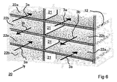
図6は、潜熱型熱交換器20のさらなる可能な実施形態を示す。潜熱型熱交換器20は、潜熱型熱交換器10と同様に、スペーサ21を間に挟んで積層される透湿性の平板状プレート12を備える。スペーサ21は、短いストリップ状の要素として構成される。しかし代替的に、スペーサ21はブロック状の要素であってもよい。スペーサ21は、例えば接着剤を用いて、平板状プレート12に固定されてもよい。フロー層22a、22bは、平板状プレート12の間に形成される。これらのフロー層22a、22b内を、エアフロー3a,3bが互いに逆方向に通過する。熱および湿気の交換は、2つの隣接するフロー層22a,22bを互いに分離する平板状プレート12を介して行われる。
FIG. 6 shows a further possible embodiment of the
図5および6を参照して説明した上述の熱交換器は、本発明の実施形態として製造される熱交換器の例示にすぎない。オランダ国特許NL2011454に記載される最新の技術は、熱交換器の可能な実施形態のさらなる例(ここでは積層は断面を有するプレートのみから構成される)を与える。 The above-described heat exchanger described with reference to FIGS. 5 and 6 is merely an example of a heat exchanger manufactured as an embodiment of the present invention. The state of the art described in the Dutch patent NL 2011 454 gives a further example of a possible embodiment of the heat exchanger (where the stack is composed only of plates with cross section).
図3aおよび3bは、ハウジング2の内部、すなわち伝達チャネルをより詳細に示す。ハウジング2は、上側および下側に、内向きの2つの突起18、19を備える。突起18、19は互いに対向し、グリッド50、51を固定するための内ねじ17が与えられる。熱交換器4、5は、突起18、19の間に組み込まれる。熱交換器4、5は、平面方向に見たとき、六面面4−1から4−6および5−1から5−2で定義される六角形状を有する。エアフロー3aの流入口31およびエアフロー3bの流出口32が、伝達チャネルのエアフロー3aが流入する側に与えられる。流入口31および流出口32は、中央隔壁33によって分離される。さらに、流入口31は壁34によって境界付けられ、流出口32は壁35によって境界付けられる。流入口31は、潜熱型熱交換器4の六角面4−1に接続する。これにより、流入口31を通って換気装置1に流入するエアフロー3aの全てが潜熱型熱交換器4を通過する。対応する空気は領域15a内で拡散し、領域15aにあるフローチャネル14aの端部に到達するだろう。エアフロー3a内の空気は、フローチャネル14aの反対側の端部でフローチャネル14aから流出し、領域15bで屈折し、六角面4−1の真正面にある六角面4−4に流入するだろう。エアフロー3aは、中央隔離体37、壁38、39、潜熱型熱交換器4の六角面4−4およびセンシブル型熱交換器5の六角面5−1で境界付けられた中間領域36に流入する。ここでエアフロー3aは、センシブル型熱交換器5に、より具体的にはセンシブル型熱交換器5の領域40aに流入する。
Figures 3a and 3b show the interior of the
ファン41が、電気モータ42および羽根43を備えるロータとともに、中間領域36に設置される。電気モータ42が起動されると、エアフロー3aは、潜熱型熱交換器4を通って吸い込まれ、センシブル型熱交換器5を通って換気装置1から吹き出されるだろう。エアフロー3aは、熱交換器5の領域40a内で分散し、熱交換器5のフローチャネル44に到達するだろう。エアフロー3aは、フローチャネル44の端部で収集領域40bに流入する。その後エアフロー3aは、六角面5−4に沿って、前記六角面5−4に隣接する流出口45(この流出口45は中央隔壁46および壁47で境界付けられる)に流入する。最後にエアフロー3aは、グリッド51を通って換気装置1から流出する。
A
同様にエアフロー3bは、グリッド51、流入口52、領域40b、フローチャネル53、領域40a、中間領域54、領域15b、フローチャネル14b、領域15a、流出口32およびグリッド50の順で、換気装置1の伝達チャネルを反対向きに通過する。エアフロー3bの運動は、ファン41と正反対を向いて中間領域54に設置されたファン55によって生成される。ハウジング2によって形成された伝達チャネルの縦方向に見たとき、ファン41および42は、少なくとも実質的には、同じ縦位置に互いに正反対を向いて設置される。
Similarly, the
図4は、図1、3aおよび3bの換気装置の代替的な実施形態60を示す。ここで再び潜熱型熱交換器4およびセンシブル型熱交換器5は、ハウジング2内で直列に配置される。しかし今度は、潜熱型熱交換器4およびセンシブル型熱交換器5は、互いにより接近して、すなわち、潜熱型熱交換器4とセンシブル型熱交換器5の六角形の頂点が接触点61で互いに接触するほど互いに接近して配置される。このことと、壁62が閉じた六角面4−3と5−2とを相互接続し、壁63が閉じた六角面4−6と5−5とを相互接続することにより、中間領域64、65は、中間領域36、54より小さいものとなる。換気装置60は、流出口68および流入口69にそれぞれ配置された2つのファン66、67を備える。流出口68および流入口69は、対応するそれぞれの流出口45および流入口52より大きい。
FIG. 4 shows an
換気装置1、60は、例えば、建物71(図2参照)の外壁70で使用されてよい。従って外壁70の外側には、円筒形の孔が設けられるだろう。外壁70の内側にはグリッド50が延び、外壁70の外側にはグリッド51が延びるだろう。エアフロー3aは、建物71から流入する空気を含み、換気装置1、60を通って建物71から外気に流出する。一方エアフロー3bは、換気装置1、60を通って建物71に流入する空気を含む。エアフロー3bは、潜熱型熱交換器4を通過中に加熱されるとともに、潜熱型熱交換器4の内部でより高湿度となる。これにより、建物71内の大気湿度を所望のレベルに保つことができる。
The
図2に、本発明に係る換気装置の代替的な応用が示される。図2は、窓枠101を備える建物を示す。この窓枠101は、外壁70に設けられる。窓枠101(図7にこの窓枠101の上部が示される)は、2つの垂直な柱102と、上部まぐさ103と、窓台(図7に示さず)とを備える。窓枠101は、換気装置111を与えられる。
An alternative application of the ventilator according to the invention is shown in FIG. FIG. 2 shows a building provided with a
換気装置111は、長方形の断面の管状のハウジング112を備える。互いに反対を向くハウジングの端部113a、113bは閉じている。開口部は、それぞれの端部113a、113bの近くで、互いに反対を向くハウジングの垂直面に与えられる。これらの開口部は、グリッド114a、115a、114b、115bによって閉鎖される。ハウジング112の内部は、2つのエアフローの伝達チャネルを構成する。
The
3つの異なるタイプの熱交換器116、117、118が、伝達チャネル内に直列に配置される。本発明の範囲内で、熱交換器116、117、118の少なくとも1つは潜熱型熱交換器であり、熱交換器116、117、118の少なくとも1つはセンシブル型熱交換器である。熱交換器116、117、118は、前述の図5および6を参照して説明したものと同じタイプのものであってよい。
Three different types of
隣接する熱交換器の互いに対向する六角形の頂点は、実質的に互いに接触する。グリッド/開口部114a、115bと、前記開口部114a、115aに対向する熱交換器116の六角形の頂点との間の位置から出発して、換気装置111は、ハウジング112内に壁120、121を与えられる。この壁120、121は、ハウジング112の全高まで延びる。同様に壁122、123が、反対側に与えられる。壁120−123は、熱交換器116、117、118とともに、エアフローチャネル124、125を定義する。エアフローチャネル124、125は、横並びに配置され、互いに反対向きのフローを有する。図8は、2つのエアフロー126および127が、通常動作時に、これらのエアフローチャネル124、125をどのように通って流れるかを示す。
The apexes of mutually opposing hexagons of adjacent heat exchangers substantially touch each other. Starting from the position between the grids /
エアフロー126、127は、ファン(図7に示さず)によって生成される。図11には、このようなファン141、142が模式的に示される。ファン141、142はハウジング112内に与えられる。さらに、ファン141は建物から流出するエアフロー内に設置される。そしてファン142は、建物71の外側を向く熱交換器116、117、118の側に与えられる。これらにより、ファン141、142が発生する目障りな雑音が限定されるだろう。
熱交換器116、117、118の高さは、ハウジング112の高さより低く、例えば後者の高さの75%である。エアフロー126のための各チャネル131、132および133(図8)を定義するために、熱交換器の上部に、平行壁128a、128b、129a、129bおよび130a、130bが与えられる。平行壁128a、128b、129a、129bおよび130a、130bのエアフロー126の向きから見たときの最前面に、各熱交換器116、117および118のためのバルブ134、135および136が与えられる。バルブ134、135、136は、上向きの閉鎖位置(図8)と、下向きの開放位置との間を、それぞれ個別に切り替えることができる。開放位置では、空間は、エアフロー126が、各バルブ134、135、136に対応する熱交換器116、117、118を自由にバイパスするように設定される。これは、熱交換器116、117、118からエアフロー126に与えられるフロー抵抗が比較的大きいことにより実現される。例えばバルブ134、135、136は、建物71の内部および外部で計測された温度および湿度の値に基づく無線操作コマンドを中央制御システムから受信する小型電気モータを用いて動かされてよい。これらのバイパスバルブは、エアフロー126、127のいずれか一方にのみ与えられれば十分である。なぜなら、熱交換器116、117、118の内部にエアフロー126、127のいずれか一方が存在しなければ、対応する熱交換器116、117、118内でのエネルギー交換は行われない(あるいは少なくとも比較的わずかである)ことが保証されるからである。しかしながら代替的に、エアフロー126、127の各々に対して、単数または複数のバルブを与えることも可能である。この場合、エアフロー126、127の各々が、1つ以上の熱交換器をバイパスすることができる。これにより、フロー抵抗を低減し、ファンに必要なパワーを低減することができる。
The height of the
バルブの好適な応用例は、例えば涼しい夏の夜に、屋内の方が屋外より高温であるような状況に見出すことができる。このようなとき、人は、涼しい屋外の空気を加熱することなく屋内に導入することを望む。この目的のために、バルブ134、135および136の1つ以上を開放位置に切り換えることができる。別の応用例は、例えば屋内が非常に高湿度であるため、屋内を乾燥させる必要があるような場合である。このようなときは、比較的乾燥した空気が建物内に導入されるように、潜熱型熱交換器をバイパスすると有効であろう。図10は、バルブ135、136が開放位置に切り替えられることによって、熱交換器117、118がバイパスされる状況を例示により示す。
Suitable applications of the valve can be found, for example, in situations where indoors are hotter than outdoors, eg on cool summer nights. At such times, one would like to introduce cool outdoor air indoors without heating. For this purpose, one or more of the
図12は、換気装置101の代替としての換気装置151を示す。換気装置151は、エアフロー126a、127aおよび熱交換器の各々に、ファン152から157が与えられるという点で換気装置101と異なる。さらに、エアフロー126a、127aは、換気装置101の場合と向きが異なる。そして熱交換器116、117、118は、互いに少し間隔をより大きく空けて配置される。これにより、ファン152、153、155、156(これらの間には隔壁158、159が与えられる)のための空間が確保される。直列に配置される複数のファン152、153、154、および155、156、157は、それぞれエアフロー126a、126bのために使用される。これにより、それぞれのファンの寸法を比較的小さくすることができる。これは特に、ハウジング112内のスペースが限られたものである場合、好ましいものとなる。さらなる代替的な実施形態では、ファン152、153、155、156を割愛してもよい。あるいは、外壁70の外側でハウジング112の外部に配置されるファン154、157を割愛してもよい。
FIG. 12 shows a
本発明に係る換気装置は、前述と別の方法で利用されてもよい。例えば、本発明に係る換気装置を、建物(住居やオフィスなど)に使われる中央換気システムとして利用することが考えられる。前述では、本発明をカウンターフローの空気を参照して説明したが、同様に本発明を同じ向きのエアフローあるいはクロスフローに適用することも可能である。さらに本発明に、六角形でない形状を有する熱交換器、例えば長方形状を有する熱交換器を適用することも可能である。例えば、本発明を複数の平行な管、例えば互いに積層された円状の管を有する熱交換器に使用することも可能である。この場合、エアフローの1つは管を通過し、他のエアフローは管の間を通過する。センシブル型熱交換器では、管の壁は非透湿性の材料から製造される。一方、潜熱型熱交換器では、管の壁は透湿性の材料から製造される。ハイブリッド熱交換器の場合、管の一部分は透湿性材料の壁であり、管の別の部分は非透湿性材料の壁であってよい。 The ventilator according to the present invention may be used in another way than the one described above. For example, it is conceivable to use the ventilation system according to the present invention as a central ventilation system used in a building (such as a residence or office). Although the invention has been described above with reference to counterflow air, it is equally possible to apply the invention to airflow or crossflow in the same direction. Furthermore, it is also possible to apply to the invention a heat exchanger having a non-hexagonal shape, for example a heat exchanger having a rectangular shape. For example, it is also possible to use the invention in heat exchangers having a plurality of parallel tubes, for example circular tubes stacked one on another. In this case, one of the airflows passes through the tubes and the other airflow passes between the tubes. In a sensible heat exchanger, the wall of the tube is made of a non-permeable material. On the other hand, in a latent heat exchanger, the wall of the tube is made of a vapor-permeable material. In the case of a hybrid heat exchanger, one portion of the tube may be the wall of the vapor permeable material and another portion of the tube may be the wall of the non-vapor permeable material.
熱交換器のプレートは、透湿性以外の特性、例えば重さ、難燃性、親水性または疎水性、衛生特性および/または一般的に原材料が、互いに異なっていてもよい。 The plates of the heat exchanger may differ from each other in properties other than moisture permeability, such as weight, flame retardancy, hydrophilicity or hydrophobicity, hygiene characteristics and / or generally raw materials.
Claims (53)
前記第1のエアフローのための第1のフローチャネルと、前記第2のエアフローのための第2のフローチャネルとが、隣接するプレート間に配置されるように積層したプレートの積層を備え、
第1のタイプのプレートと第2のタイプのプレートとが前記積層内に与えられ、
前記第1のタイプのプレートと前記第2のタイプのプレートとは、重さおよび/または原材料が互いに異なることを特徴とする熱交換器。 A heat exchanger for exchanging energy between a first air flow and a second air flow, the heat exchanger comprising:
Comprising a stack of plates stacked such that a first flow channel for the first air flow and a second flow channel for the second air flow are disposed between adjacent plates,
A first type of plate and a second type of plate are provided in the stack,
A heat exchanger characterized in that the plates of the first type and the plates of the second type differ in weight and / or raw materials from one another.
2つのエアフローのための伝達チャネルを内部に備えるハウジングと、
前記伝達チャネル内に配置される少なくとも1つの第1のタイプの熱交換器と、を備え、
前記第1のタイプの熱交換器は、前記第1のエアフローのための第1のさらなるフローチャネルと、前記第2のエアフローのための第2のさらなるフローチャネルと、を備え、
隣接する前記第1のさらなるフローチャネルと、前記第2のさらなるフローチャネルとは、少なくとも部分的には、非透湿性の壁によって互いに分離されており、
前記伝達チャネル内には、前記第1のタイプの熱交換器と直列に、少なくとも1つの請求項3に記載の潜熱型熱交換器が配置されることを特徴とする換気装置。 A ventilation system for exchanging energy between a first air flow flowing into the building from the outside air and a second air flow flowing out from the building into the air,
A housing internally provided with transmission channels for the two air flows;
And at least one first type of heat exchanger disposed in the transfer channel;
The first type of heat exchanger comprises a first further flow channel for the first air flow and a second further flow channel for the second air flow,
The adjacent first further flow channel and the second further flow channel are at least partially separated from one another by a non-permeable wall,
4. A ventilator as claimed in claim 3, wherein at least one latent heat exchanger according to claim 3 is arranged in the transfer channel in series with the first type of heat exchanger.
前記第1のさらなるフローチャネルと、前記第2のさらなるフローチャネルとは、隣接するプレートの間に形成されることを特徴とする請求項17または18に記載の換気装置。 The first type of heat exchanger comprises stacked plates,
19. A ventilator as claimed in claim 17 or 18, wherein the first further flow channel and the second further flow channel are formed between adjacent plates.
前記ハイブリッド熱交換器は、前記第1のタイプの熱交換器のプレートの一部のみが、非透湿性の材料から製造されることを特徴とする請求項17から22のいずれか一項に記載の換気装置。 At least one said first type of heat exchanger being a hybrid heat exchanger;
23. The hybrid heat exchanger according to any one of the claims 17-22, characterized in that only a part of the plates of the first type of heat exchanger is made of a non-moisture permeable material. Ventilation system.
前記第1位置では、エアフローは、少なくとも実質的には、前記第1位置に対応する熱交換器を通り、
前記第2位置では、エアフローは、少なくとも実質的には、前記熱交換器をバイパスして流れるようにバルブによって導かれることを特徴とする請求項17から36のいずれか一項に記載の換気装置。 At least one valve is provided which can switch between the first position and the second position,
In said first position, the air flow is at least substantially through a heat exchanger corresponding to said first position,
37. A ventilator as claimed in any one of claims 17 to 36, wherein in the second position air flow is directed at least substantially by the valve to flow bypassing the heat exchanger. .
バルブが熱交換器の積層の上または下に与えられ、
前記バルブは、第2位置にあるときは、エアフローが各熱交換器をバイパスするように、前記エアフローを各熱交換器の上または下に導くことを特徴とする請求項17から37のいずれか一項に記載の換気装置。 The heat exchanger of the first type and / or a plate on which the latent heat exchanger is stacked;
Valves are provided above or below the stack of heat exchangers,
38. The valve according to any one of claims 17 to 37, wherein when in the second position, the air flow is directed to the top or bottom of each heat exchanger such that the air flow bypasses each heat exchanger. Ventilator according to one item.
2つのエアフローのための伝達チャネルを内部に備えるハウジングと、
前記伝達チャネル内に配置される少なくとも1つの第1のタイプの熱交換器と、を備え、
前記第1のタイプの熱交換器は、前記第1のエアフローのための第1のさらなるフローチャネルと、前記第2のエアフローのための第2のさらなるフローチャネルと、を備え、
隣接する前記第1のさらなるフローチャネルと、前記第2のさらなるフローチャネルとは、少なくとも部分的には、非透湿性の壁によって互いに分離されており、
前記伝達チャネル内には、前記第1のタイプの熱交換器と直列に、少なくとも1つの潜熱型熱交換器が配置されることを特徴とする換気装置。 A ventilation system for exchanging energy between a first air flow flowing into the building from the outside air and a second air flow flowing out from the building into the air,
A housing internally provided with transmission channels for the two air flows;
And at least one first type of heat exchanger disposed in the transfer channel;
The first type of heat exchanger comprises a first further flow channel for the first air flow and a second further flow channel for the second air flow,
The adjacent first further flow channel and the second further flow channel are at least partially separated from one another by a non-permeable wall,
At least one latent heat exchanger is disposed in the transfer channel in series with the first type of heat exchanger.
前記ハウジングは、前記換気装置を通して前記建物内に流入するエアフローと、前記換気装置を通して前記建物外に流出するエアフローとの間でエネルギーを交換するために、前記建物の外壁にある孔の内部に与えられることを特徴とする建物。 44. A building comprising the ventilating device according to any one of claims 17 to 43, wherein
The housing is provided inside a hole in an outer wall of the building to exchange energy between an air flow entering the building through the ventilating device and an air flow flowing out of the building through the ventilating device. Building characterized by being
Applications Claiming Priority (3)
| Application Number | Priority Date | Filing Date | Title |
|---|---|---|---|
| NL2016731A NL2016731B1 (en) | 2016-05-03 | 2016-05-03 | Device for exchanging energy between two air flows. |
| NL2016731 | 2016-05-03 | ||
| PCT/NL2017/050281 WO2017192038A1 (en) | 2016-05-03 | 2017-05-03 | Recuperator for exchanging energy between two air flows |
Publications (3)
| Publication Number | Publication Date |
|---|---|
| JP2019515244A true JP2019515244A (en) | 2019-06-06 |
| JP2019515244A5 JP2019515244A5 (en) | 2020-04-02 |
| JP6955551B2 JP6955551B2 (en) | 2021-10-27 |
Family
ID=56292845
Family Applications (1)
| Application Number | Title | Priority Date | Filing Date |
|---|---|---|---|
| JP2019510757A Active JP6955551B2 (en) | 2016-05-03 | 2017-05-03 | A heat exchanger that exchanges energy between two airflows |
Country Status (11)
| Country | Link |
|---|---|
| US (1) | US20190137137A1 (en) |
| EP (1) | EP3452760B1 (en) |
| JP (1) | JP6955551B2 (en) |
| CN (1) | CN109416190A (en) |
| CA (1) | CA3022931C (en) |
| DK (1) | DK3452760T3 (en) |
| ES (1) | ES2779807T3 (en) |
| LT (1) | LT3452760T (en) |
| NL (1) | NL2016731B1 (en) |
| PL (1) | PL3452760T3 (en) |
| WO (1) | WO2017192038A1 (en) |
Cited By (1)
| Publication number | Priority date | Publication date | Assignee | Title |
|---|---|---|---|---|
| WO2026053574A1 (en) * | 2024-09-03 | 2026-03-12 | シャープ株式会社 | Heat exchange ventilation device |
Families Citing this family (4)
| Publication number | Priority date | Publication date | Assignee | Title |
|---|---|---|---|---|
| US10932420B2 (en) | 2018-04-19 | 2021-03-02 | Therma-Stor, Llc | Greenhouse latent moisture and heat exchanger |
| CN113739315A (en) * | 2021-09-18 | 2021-12-03 | 中山市骏伟电器有限公司 | New fan of heat transfer |
| CN114894012A (en) * | 2022-05-07 | 2022-08-12 | 佛山市科蓝环保科技股份有限公司 | Cross type heat exchange structure and heat exchanger |
| CN115789831A (en) * | 2022-12-08 | 2023-03-14 | 珠海格力节能环保制冷技术研究中心有限公司 | New fan |
Citations (11)
| Publication number | Priority date | Publication date | Assignee | Title |
|---|---|---|---|---|
| JPS604831U (en) * | 1983-06-23 | 1985-01-14 | 株式会社東芝 | air conditioner |
| JPS6131888A (en) * | 1984-07-25 | 1986-02-14 | Matsushita Electric Ind Co Ltd | Heat exchanging device |
| JPH02225929A (en) * | 1989-02-27 | 1990-09-07 | Matsushita Seiko Co Ltd | Air conditioning and ventilating device |
| JPH10141726A (en) * | 1996-11-05 | 1998-05-29 | Aisin Seiki Co Ltd | Tone ventilation fan |
| JPH11337144A (en) * | 1998-05-25 | 1999-12-10 | Tetsuya Saigo | Heat exchange and ventilation equipment |
| JP2000111279A (en) * | 1998-10-09 | 2000-04-18 | Calsonic Corp | Total heat exchanger frame and total heat exchanger using the same |
| JP2001027489A (en) * | 1999-05-10 | 2001-01-30 | Mitsubishi Electric Corp | Heat exchanger and method of manufacturing heat exchanger |
| US20080156471A1 (en) * | 2006-12-28 | 2008-07-03 | Lg Electronics Inc. | Heat exchange element for ventilating apparatus |
| JP2011012894A (en) * | 2009-07-02 | 2011-01-20 | Panasonic Corp | Material for total heat exchange element and heat exchange type ventilation device using the material |
| JP2015509178A (en) * | 2011-12-19 | 2015-03-26 | ディーポイント テクノロジーズ インコーポレイテッドdPoint Technologies Inc. | Counter-current energy recovery ventilator (ERV) core |
| WO2015069178A1 (en) * | 2013-11-07 | 2015-05-14 | Air To Air Sweden Ab | A sheet for exchange of heat or mass transfer between fluid flows, a device comprising such a sheet, and a method of manufacturing the sheet |
Family Cites Families (8)
| Publication number | Priority date | Publication date | Assignee | Title |
|---|---|---|---|---|
| CA2625198C (en) * | 2005-11-02 | 2013-08-20 | Air Tech Equipment Ltd. | Energy recovery and humidity control system |
| KR100737695B1 (en) * | 2006-06-28 | 2007-07-09 | 이찬봉 | Heating element with improved liner |
| KR20100120313A (en) * | 2008-04-16 | 2010-11-15 | 미쓰비시덴키 가부시키가이샤 | Heat exchanging ventilating apparatus |
| JP5405801B2 (en) * | 2008-11-07 | 2014-02-05 | ヤンマー株式会社 | Desiccant air conditioner |
| NL2003671C2 (en) * | 2009-10-19 | 2011-04-20 | Level Holding Bv | CLIMATE MANAGEMENT DEVICE FOR CASES. |
| US20140014289A1 (en) * | 2012-07-11 | 2014-01-16 | Kraton Polymers U.S. Llc | Enhanced-efficiency energy recovery ventilation core |
| NL2011454C2 (en) | 2013-09-17 | 2015-03-18 | Level Holding Bv | HEAT EXCHANGER WITH IMPROVED GEOMETRY. |
| NL2012548B1 (en) | 2014-04-02 | 2016-02-15 | Level Holding Bv | Recuperator, the heat exchange channels of which extend transversely to the longitudinal direction of the housing. |
-
2016
- 2016-05-03 NL NL2016731A patent/NL2016731B1/en not_active IP Right Cessation
-
2017
- 2017-05-03 EP EP17727411.5A patent/EP3452760B1/en active Active
- 2017-05-03 ES ES17727411T patent/ES2779807T3/en active Active
- 2017-05-03 JP JP2019510757A patent/JP6955551B2/en active Active
- 2017-05-03 CA CA3022931A patent/CA3022931C/en active Active
- 2017-05-03 WO PCT/NL2017/050281 patent/WO2017192038A1/en not_active Ceased
- 2017-05-03 PL PL17727411T patent/PL3452760T3/en unknown
- 2017-05-03 US US16/099,019 patent/US20190137137A1/en not_active Abandoned
- 2017-05-03 CN CN201780041239.5A patent/CN109416190A/en active Pending
- 2017-05-03 DK DK17727411.5T patent/DK3452760T3/en active
- 2017-05-03 LT LTEP17727411.5T patent/LT3452760T/en unknown
Patent Citations (11)
| Publication number | Priority date | Publication date | Assignee | Title |
|---|---|---|---|---|
| JPS604831U (en) * | 1983-06-23 | 1985-01-14 | 株式会社東芝 | air conditioner |
| JPS6131888A (en) * | 1984-07-25 | 1986-02-14 | Matsushita Electric Ind Co Ltd | Heat exchanging device |
| JPH02225929A (en) * | 1989-02-27 | 1990-09-07 | Matsushita Seiko Co Ltd | Air conditioning and ventilating device |
| JPH10141726A (en) * | 1996-11-05 | 1998-05-29 | Aisin Seiki Co Ltd | Tone ventilation fan |
| JPH11337144A (en) * | 1998-05-25 | 1999-12-10 | Tetsuya Saigo | Heat exchange and ventilation equipment |
| JP2000111279A (en) * | 1998-10-09 | 2000-04-18 | Calsonic Corp | Total heat exchanger frame and total heat exchanger using the same |
| JP2001027489A (en) * | 1999-05-10 | 2001-01-30 | Mitsubishi Electric Corp | Heat exchanger and method of manufacturing heat exchanger |
| US20080156471A1 (en) * | 2006-12-28 | 2008-07-03 | Lg Electronics Inc. | Heat exchange element for ventilating apparatus |
| JP2011012894A (en) * | 2009-07-02 | 2011-01-20 | Panasonic Corp | Material for total heat exchange element and heat exchange type ventilation device using the material |
| JP2015509178A (en) * | 2011-12-19 | 2015-03-26 | ディーポイント テクノロジーズ インコーポレイテッドdPoint Technologies Inc. | Counter-current energy recovery ventilator (ERV) core |
| WO2015069178A1 (en) * | 2013-11-07 | 2015-05-14 | Air To Air Sweden Ab | A sheet for exchange of heat or mass transfer between fluid flows, a device comprising such a sheet, and a method of manufacturing the sheet |
Cited By (1)
| Publication number | Priority date | Publication date | Assignee | Title |
|---|---|---|---|---|
| WO2026053574A1 (en) * | 2024-09-03 | 2026-03-12 | シャープ株式会社 | Heat exchange ventilation device |
Also Published As
| Publication number | Publication date |
|---|---|
| CA3022931A1 (en) | 2017-11-09 |
| CN109416190A (en) | 2019-03-01 |
| EP3452760B1 (en) | 2020-03-04 |
| NL2016731B1 (en) | 2017-11-10 |
| LT3452760T (en) | 2020-06-10 |
| DK3452760T3 (en) | 2020-03-30 |
| ES2779807T3 (en) | 2020-08-19 |
| EP3452760A1 (en) | 2019-03-13 |
| US20190137137A1 (en) | 2019-05-09 |
| CA3022931C (en) | 2025-05-13 |
| WO2017192038A1 (en) | 2017-11-09 |
| PL3452760T3 (en) | 2020-06-01 |
| JP6955551B2 (en) | 2021-10-27 |
Similar Documents
| Publication | Publication Date | Title |
|---|---|---|
| US11578881B2 (en) | Enthalpy exchanger | |
| US9140471B2 (en) | Indirect evaporative coolers with enhanced heat transfer | |
| CN102007346B (en) | Heat exchanging ventilating apparatus | |
| JP6955551B2 (en) | A heat exchanger that exchanges energy between two airflows | |
| US20140262125A1 (en) | Energy exchange assembly with microporous membrane | |
| US20090178780A1 (en) | Flat plate heat exchanger | |
| CN102906509B (en) | For the ventilation equipment with heat pipe of window | |
| US20160131373A1 (en) | Architectural heat and moisture exchange | |
| CN107923636A (en) | Ways to Harvest Energy from Humidity Changes | |
| JP5987854B2 (en) | Heat exchange element and heat exchanger | |
| CN111919078A (en) | Total heat exchange element and total heat exchanger | |
| JP2019515244A5 (en) | ||
| CN106949586B (en) | Anhydrous humidification device and air conditioner | |
| WO2008051098A2 (en) | A heat exchanger, a heat sink and a heat exchange system | |
| JP2006145092A (en) | Air conditioning system and building | |
| KR101431211B1 (en) | Electrical Heating Element Using Counterflow Ventilation Unit | |
| JP3115391U (en) | Fixed wet dehumidification and energy recovery device | |
| EP4722611A1 (en) | Heat recovery unit and method of operating the same | |
| JP5986532B2 (en) | Building floor heating system | |
| JP3156162U (en) | Total heat exchange element | |
| JP7569240B2 (en) | Housing | |
| CN202350284U (en) | Total heat exchange unit | |
| KR102097678B1 (en) | Adsorption type device for removing latent heat integrated with stack type adsorption inner structure | |
| JP2016223701A (en) | Air conditioning system | |
| WO2022014651A1 (en) | Humidity control element, humidity control module, and humidity control system |
Legal Events
| Date | Code | Title | Description |
|---|---|---|---|
| A711 | Notification of change in applicant |
Free format text: JAPANESE INTERMEDIATE CODE: A711 Effective date: 20191021 |
|
| A521 | Request for written amendment filed |
Free format text: JAPANESE INTERMEDIATE CODE: A821 Effective date: 20191021 |
|
| A521 | Request for written amendment filed |
Free format text: JAPANESE INTERMEDIATE CODE: A523 Effective date: 20200217 |
|
| A621 | Written request for application examination |
Free format text: JAPANESE INTERMEDIATE CODE: A621 Effective date: 20200217 |
|
| A977 | Report on retrieval |
Free format text: JAPANESE INTERMEDIATE CODE: A971007 Effective date: 20210225 |
|
| A131 | Notification of reasons for refusal |
Free format text: JAPANESE INTERMEDIATE CODE: A131 Effective date: 20210309 |
|
| A521 | Request for written amendment filed |
Free format text: JAPANESE INTERMEDIATE CODE: A523 Effective date: 20210608 |
|
| TRDD | Decision of grant or rejection written | ||
| A01 | Written decision to grant a patent or to grant a registration (utility model) |
Free format text: JAPANESE INTERMEDIATE CODE: A01 Effective date: 20210928 |
|
| A61 | First payment of annual fees (during grant procedure) |
Free format text: JAPANESE INTERMEDIATE CODE: A61 Effective date: 20211001 |
|
| R150 | Certificate of patent or registration of utility model |
Ref document number: 6955551 Country of ref document: JP Free format text: JAPANESE INTERMEDIATE CODE: R150 |
|
| R250 | Receipt of annual fees |
Free format text: JAPANESE INTERMEDIATE CODE: R250 |
|
| R250 | Receipt of annual fees |
Free format text: JAPANESE INTERMEDIATE CODE: R250 |