JP2019514591A - Automated wound binding detection in negative pressure wound therapy systems - Google Patents
Automated wound binding detection in negative pressure wound therapy systems Download PDFInfo
- Publication number
- JP2019514591A JP2019514591A JP2018558161A JP2018558161A JP2019514591A JP 2019514591 A JP2019514591 A JP 2019514591A JP 2018558161 A JP2018558161 A JP 2018558161A JP 2018558161 A JP2018558161 A JP 2018558161A JP 2019514591 A JP2019514591 A JP 2019514591A
- Authority
- JP
- Japan
- Prior art keywords
- wound
- negative pressure
- fluid flow
- indicator
- wound dressing
- Prior art date
- Legal status (The legal status is an assumption and is not a legal conclusion. Google has not performed a legal analysis and makes no representation as to the accuracy of the status listed.)
- Pending
Links
- 206010052428 Wound Diseases 0.000 title claims abstract description 339
- 208000027418 Wounds and injury Diseases 0.000 title claims abstract description 339
- 238000009581 negative-pressure wound therapy Methods 0.000 title claims abstract description 13
- 238000001514 detection method Methods 0.000 title claims description 25
- 239000012530 fluid Substances 0.000 claims abstract description 151
- 238000000034 method Methods 0.000 claims abstract description 79
- 230000000739 chaotic effect Effects 0.000 claims abstract description 11
- 230000008859 change Effects 0.000 claims description 66
- 238000002560 therapeutic procedure Methods 0.000 claims description 52
- 230000001364 causal effect Effects 0.000 claims description 39
- 230000004044 response Effects 0.000 claims description 36
- 230000001186 cumulative effect Effects 0.000 claims description 31
- 210000000416 exudates and transudate Anatomy 0.000 claims description 31
- 238000001914 filtration Methods 0.000 claims description 16
- 238000004891 communication Methods 0.000 claims description 14
- 238000005259 measurement Methods 0.000 claims description 12
- 239000000463 material Substances 0.000 claims description 9
- 238000012731 temporal analysis Methods 0.000 claims description 9
- 238000000700 time series analysis Methods 0.000 claims description 9
- 239000008280 blood Substances 0.000 claims description 8
- 210000004369 blood Anatomy 0.000 claims description 8
- 238000003860 storage Methods 0.000 claims description 7
- 238000012544 monitoring process Methods 0.000 claims description 6
- 230000004913 activation Effects 0.000 claims description 4
- 230000002459 sustained effect Effects 0.000 claims description 2
- 230000008569 process Effects 0.000 description 17
- 239000000945 filler Substances 0.000 description 10
- 238000012545 processing Methods 0.000 description 9
- 210000001519 tissue Anatomy 0.000 description 8
- 230000007423 decrease Effects 0.000 description 6
- 230000033001 locomotion Effects 0.000 description 6
- 238000004458 analytical method Methods 0.000 description 4
- 230000008901 benefit Effects 0.000 description 3
- 230000017531 blood circulation Effects 0.000 description 3
- 238000009530 blood pressure measurement Methods 0.000 description 3
- 230000035876 healing Effects 0.000 description 3
- 239000007788 liquid Substances 0.000 description 3
- 229920001296 polysiloxane Polymers 0.000 description 3
- 230000029058 respiratory gaseous exchange Effects 0.000 description 3
- 230000000007 visual effect Effects 0.000 description 3
- XLYOFNOQVPJJNP-UHFFFAOYSA-N water Chemical compound O XLYOFNOQVPJJNP-UHFFFAOYSA-N 0.000 description 3
- 230000003321 amplification Effects 0.000 description 2
- 230000000845 anti-microbial effect Effects 0.000 description 2
- 239000004599 antimicrobial Substances 0.000 description 2
- 230000008878 coupling Effects 0.000 description 2
- 238000010168 coupling process Methods 0.000 description 2
- 238000005859 coupling reaction Methods 0.000 description 2
- 230000000694 effects Effects 0.000 description 2
- 229920001971 elastomer Polymers 0.000 description 2
- 230000006870 function Effects 0.000 description 2
- 208000014674 injury Diseases 0.000 description 2
- 230000001788 irregular Effects 0.000 description 2
- 238000003199 nucleic acid amplification method Methods 0.000 description 2
- 230000000737 periodic effect Effects 0.000 description 2
- 239000004033 plastic Substances 0.000 description 2
- 229920003023 plastic Polymers 0.000 description 2
- 238000003825 pressing Methods 0.000 description 2
- 230000001225 therapeutic effect Effects 0.000 description 2
- 238000012546 transfer Methods 0.000 description 2
- 230000008733 trauma Effects 0.000 description 2
- 208000034656 Contusions Diseases 0.000 description 1
- 208000033770 Device misuse Diseases 0.000 description 1
- 208000034693 Laceration Diseases 0.000 description 1
- 239000004677 Nylon Substances 0.000 description 1
- 206010030113 Oedema Diseases 0.000 description 1
- 239000004698 Polyethylene Substances 0.000 description 1
- 208000004210 Pressure Ulcer Diseases 0.000 description 1
- 241000098700 Sarcocheilichthys parvus Species 0.000 description 1
- 208000002847 Surgical Wound Diseases 0.000 description 1
- 206010044546 Traumatic ulcer Diseases 0.000 description 1
- 208000025865 Ulcer Diseases 0.000 description 1
- 208000000558 Varicose Ulcer Diseases 0.000 description 1
- 230000001154 acute effect Effects 0.000 description 1
- 230000001580 bacterial effect Effects 0.000 description 1
- 230000009286 beneficial effect Effects 0.000 description 1
- 238000004364 calculation method Methods 0.000 description 1
- 230000010267 cellular communication Effects 0.000 description 1
- 230000001684 chronic effect Effects 0.000 description 1
- 239000000701 coagulant Substances 0.000 description 1
- 239000003086 colorant Substances 0.000 description 1
- 238000013016 damping Methods 0.000 description 1
- 230000009849 deactivation Effects 0.000 description 1
- 230000006837 decompression Effects 0.000 description 1
- 230000007547 defect Effects 0.000 description 1
- 206010012601 diabetes mellitus Diseases 0.000 description 1
- 238000001704 evaporation Methods 0.000 description 1
- 230000008020 evaporation Effects 0.000 description 1
- 239000006260 foam Substances 0.000 description 1
- 230000037313 granulation tissue formation Effects 0.000 description 1
- 230000036541 health Effects 0.000 description 1
- 230000002209 hydrophobic effect Effects 0.000 description 1
- 208000015181 infectious disease Diseases 0.000 description 1
- 238000004519 manufacturing process Methods 0.000 description 1
- 238000000691 measurement method Methods 0.000 description 1
- 238000012986 modification Methods 0.000 description 1
- 230000004048 modification Effects 0.000 description 1
- 229920001778 nylon Polymers 0.000 description 1
- 230000003287 optical effect Effects 0.000 description 1
- 230000002572 peristaltic effect Effects 0.000 description 1
- 230000035699 permeability Effects 0.000 description 1
- 230000004962 physiological condition Effects 0.000 description 1
- -1 polyethylene Polymers 0.000 description 1
- 229920000573 polyethylene Polymers 0.000 description 1
- 229920002635 polyurethane Polymers 0.000 description 1
- 239000004814 polyurethane Substances 0.000 description 1
- 229920000915 polyvinyl chloride Polymers 0.000 description 1
- 239000004800 polyvinyl chloride Substances 0.000 description 1
- 230000000750 progressive effect Effects 0.000 description 1
- 230000001737 promoting effect Effects 0.000 description 1
- 230000001012 protector Effects 0.000 description 1
- APTZNLHMIGJTEW-UHFFFAOYSA-N pyraflufen-ethyl Chemical compound C1=C(Cl)C(OCC(=O)OCC)=CC(C=2C(=C(OC(F)F)N(C)N=2)Cl)=C1F APTZNLHMIGJTEW-UHFFFAOYSA-N 0.000 description 1
- 230000009467 reduction Effects 0.000 description 1
- 230000002441 reversible effect Effects 0.000 description 1
- 230000033764 rhythmic process Effects 0.000 description 1
- 238000007789 sealing Methods 0.000 description 1
- 238000000926 separation method Methods 0.000 description 1
- 239000002893 slag Substances 0.000 description 1
- 239000000126 substance Substances 0.000 description 1
- 238000006467 substitution reaction Methods 0.000 description 1
- 230000000699 topical effect Effects 0.000 description 1
- 239000012780 transparent material Substances 0.000 description 1
- 230000000472 traumatic effect Effects 0.000 description 1
- 231100000397 ulcer Toxicity 0.000 description 1
- 238000011144 upstream manufacturing Methods 0.000 description 1
- 230000035899 viability Effects 0.000 description 1
Images


Classifications
-
- A61F13/05—
-
- A—HUMAN NECESSITIES
- A61—MEDICAL OR VETERINARY SCIENCE; HYGIENE
- A61M—DEVICES FOR INTRODUCING MEDIA INTO, OR ONTO, THE BODY; DEVICES FOR TRANSDUCING BODY MEDIA OR FOR TAKING MEDIA FROM THE BODY; DEVICES FOR PRODUCING OR ENDING SLEEP OR STUPOR
- A61M1/00—Suction or pumping devices for medical purposes; Devices for carrying-off, for treatment of, or for carrying-over, body-liquids; Drainage systems
- A61M1/90—Negative pressure wound therapy devices, i.e. devices for applying suction to a wound to promote healing, e.g. including a vacuum dressing
- A61M1/96—Suction control thereof
-
- A—HUMAN NECESSITIES
- A61—MEDICAL OR VETERINARY SCIENCE; HYGIENE
- A61M—DEVICES FOR INTRODUCING MEDIA INTO, OR ONTO, THE BODY; DEVICES FOR TRANSDUCING BODY MEDIA OR FOR TAKING MEDIA FROM THE BODY; DEVICES FOR PRODUCING OR ENDING SLEEP OR STUPOR
- A61M1/00—Suction or pumping devices for medical purposes; Devices for carrying-off, for treatment of, or for carrying-over, body-liquids; Drainage systems
- A61M1/71—Suction drainage systems
- A61M1/74—Suction control
-
- A—HUMAN NECESSITIES
- A61—MEDICAL OR VETERINARY SCIENCE; HYGIENE
- A61M—DEVICES FOR INTRODUCING MEDIA INTO, OR ONTO, THE BODY; DEVICES FOR TRANSDUCING BODY MEDIA OR FOR TAKING MEDIA FROM THE BODY; DEVICES FOR PRODUCING OR ENDING SLEEP OR STUPOR
- A61M1/00—Suction or pumping devices for medical purposes; Devices for carrying-off, for treatment of, or for carrying-over, body-liquids; Drainage systems
- A61M1/90—Negative pressure wound therapy devices, i.e. devices for applying suction to a wound to promote healing, e.g. including a vacuum dressing
- A61M1/96—Suction control thereof
- A61M1/966—Suction control thereof having a pressure sensor on or near the dressing
-
- A—HUMAN NECESSITIES
- A61—MEDICAL OR VETERINARY SCIENCE; HYGIENE
- A61M—DEVICES FOR INTRODUCING MEDIA INTO, OR ONTO, THE BODY; DEVICES FOR TRANSDUCING BODY MEDIA OR FOR TAKING MEDIA FROM THE BODY; DEVICES FOR PRODUCING OR ENDING SLEEP OR STUPOR
- A61M1/00—Suction or pumping devices for medical purposes; Devices for carrying-off, for treatment of, or for carrying-over, body-liquids; Drainage systems
- A61M1/90—Negative pressure wound therapy devices, i.e. devices for applying suction to a wound to promote healing, e.g. including a vacuum dressing
- A61M1/98—Containers specifically adapted for negative pressure wound therapy
- A61M1/982—Containers specifically adapted for negative pressure wound therapy with means for detecting level of collected exudate
-
- A—HUMAN NECESSITIES
- A61—MEDICAL OR VETERINARY SCIENCE; HYGIENE
- A61M—DEVICES FOR INTRODUCING MEDIA INTO, OR ONTO, THE BODY; DEVICES FOR TRANSDUCING BODY MEDIA OR FOR TAKING MEDIA FROM THE BODY; DEVICES FOR PRODUCING OR ENDING SLEEP OR STUPOR
- A61M2205/00—General characteristics of the apparatus
- A61M2205/13—General characteristics of the apparatus with means for the detection of operative contact with patient, e.g. lip sensor
-
- A—HUMAN NECESSITIES
- A61—MEDICAL OR VETERINARY SCIENCE; HYGIENE
- A61M—DEVICES FOR INTRODUCING MEDIA INTO, OR ONTO, THE BODY; DEVICES FOR TRANSDUCING BODY MEDIA OR FOR TAKING MEDIA FROM THE BODY; DEVICES FOR PRODUCING OR ENDING SLEEP OR STUPOR
- A61M2205/00—General characteristics of the apparatus
- A61M2205/33—Controlling, regulating or measuring
- A61M2205/3331—Pressure; Flow
- A61M2205/3334—Measuring or controlling the flow rate
-
- A—HUMAN NECESSITIES
- A61—MEDICAL OR VETERINARY SCIENCE; HYGIENE
- A61M—DEVICES FOR INTRODUCING MEDIA INTO, OR ONTO, THE BODY; DEVICES FOR TRANSDUCING BODY MEDIA OR FOR TAKING MEDIA FROM THE BODY; DEVICES FOR PRODUCING OR ENDING SLEEP OR STUPOR
- A61M2205/00—General characteristics of the apparatus
- A61M2205/33—Controlling, regulating or measuring
- A61M2205/3331—Pressure; Flow
- A61M2205/3344—Measuring or controlling pressure at the body treatment site
-
- A—HUMAN NECESSITIES
- A61—MEDICAL OR VETERINARY SCIENCE; HYGIENE
- A61M—DEVICES FOR INTRODUCING MEDIA INTO, OR ONTO, THE BODY; DEVICES FOR TRANSDUCING BODY MEDIA OR FOR TAKING MEDIA FROM THE BODY; DEVICES FOR PRODUCING OR ENDING SLEEP OR STUPOR
- A61M2205/00—General characteristics of the apparatus
- A61M2205/50—General characteristics of the apparatus with microprocessors or computers
- A61M2205/52—General characteristics of the apparatus with microprocessors or computers with memories providing a history of measured variating parameters of apparatus or patient
Abstract
陰圧創傷療法システムおよびそのシステムを動作する方法の実施形態が開示されている。一部の実施形態では、システムは、陰圧源、センサおよびコントローラを含む。陰圧源は、流体流路を介して創傷被覆材に陰圧を与えることができる。センサは、流体流路内の圧力を監視することができる。コントローラは、陰圧源が圧力範囲内に流体流路内の陰圧を維持する間、混沌とした状態よりも定常状態を示す経時的な流体流路内の圧力の大きさの変化から、創傷被覆材が創傷に結合されているかどうかを決定することができる。さらに、コントローラは、創傷被覆材が創傷に結合されていることを示す第1の表示、および創傷被覆材が創傷に結合されていないことを示す第2の表示を出力することができる。【選択図】図5Embodiments of a negative pressure wound therapy system and methods of operating the system are disclosed. In some embodiments, the system includes a negative pressure source, a sensor and a controller. A negative pressure source can provide negative pressure to the wound dressing via the fluid flow path. A sensor can monitor the pressure in the fluid flow path. The controller changes the magnitude of pressure in the fluid flow path over time showing steady state rather than chaotic conditions while the negative pressure source maintains the negative pressure in the fluid flow path within the pressure range. It can be determined whether the dressing is attached to the wound. Additionally, the controller can output a first indication that the wound dressing is coupled to the wound, and a second indication that the wound dressing is not coupled to the wound. [Selected figure] Figure 5
Description
関連出願の相互参照
本出願は、2016年5月13日に出願された米国仮出願第62/335,978号と2016年8月24日に出願された米国仮出願第62/378,856号の利益を主張するものであり、これらの開示はその全体が参照によって本明細書に援用される。
This application claims the benefit of U.S. Provisional Application No. 62 / 335,978, filed May 13, 2016, and U.S. Provisional Application No. 62 / 378,856, filed August 24, 2016. The disclosure of which is incorporated herein by reference in its entirety.
本開示の実施形態は、陰圧療法もしくは減圧療法または局所陰圧(TNP)療法を用いて、創傷を被覆かつ治療するための方法及び装置に関する。具体的には、限定するものではないが、本明細書に開示された実施形態は、陰圧療法デバイス、TNPシステムの動作を制御するための方法、及びTNPシステムの使用方法に関する。 Embodiments of the present disclosure relate to methods and devices for covering and treating wounds using negative pressure therapy or reduced pressure therapy or topical negative pressure (TNP) therapy. In particular, but not by way of limitation, the embodiments disclosed herein relate to a negative pressure therapy device, a method for controlling the operation of the TNP system, and a method of using the TNP system.
本開示の実施形態について、添付の図面を参照して、例としてのみ以下に記載する。 Embodiments of the present disclosure will now be described, by way of example only, with reference to the accompanying drawings.
一部の実施形態では、創傷への陰圧を適用するための装置が開示される。装置は、創傷被覆材に流体流路を介して結合し、創傷被覆材に陰圧を与えるように構成される、陰圧源と、流体流路内の圧力を監視するように構成される、センサと、陰圧源が目標圧力範囲内に流体流路内の陰圧を維持する間、創傷被覆材が、定常状態を示す継続時間を通じて流体流路内の圧力の大きさの変化から創傷に結合されたことを決定し、創傷被覆材が創傷に結合されていることを示す第1の表示を出力し、また陰圧源が目標圧力範囲内に流体流路内の陰圧を維持する間、創傷被覆材が、混沌とした状態を示す継続時間を通じて流体流路内の圧力の大きさの変化から創傷に結合されていないことを決定し、創傷被覆材が創傷に結合されていないことを示す第1の表示とは異なる第2の表示を出力するように構成される、コントローラと、を含むことができる。 In some embodiments, an apparatus for applying negative pressure to a wound is disclosed. The device is configured to couple to the wound dressing via the fluid flow path and is configured to apply negative pressure to the wound dressing, and to monitor the pressure in the fluid flow path. While the sensor and the negative pressure source maintain the negative pressure in the fluid flow path within the target pressure range, the wound dressing exhibits a steady state from the change in pressure magnitude in the fluid flow path to the wound Determines that it has been bonded and outputs a first indication that the wound dressing is bonded to the wound, and while the negative pressure source maintains negative pressure in the fluid flow path within the target pressure range Determining that the wound dressing is not bonded to the wound from the change in magnitude of the pressure in the fluid flow path over a sustained period of time indicating a chaotic condition, and that the wound dressing is not bonded to the wound A controller configured to output a second display different from the first display shown , It can contain.
上記の段落に記載の装置は、以下の特徴のうちの1つ以上を含み得る:コントローラは、創傷被覆材が創傷に結合されている決定に応じて、陰圧源の準拠した使用を示すデバイス使用データをメモリデバイスに記憶するようにさらに構成される。コントローラは、創傷被覆材が創傷に結合されていない決定に応じて、陰圧源の誤った使用を示すデバイス使用データをメモリデバイスに記憶するようにさらに構成される。デバイス使用データは、圧力レベル、アラーム、滲出液レベル、イベントログ、または療法継続時間のうち1つ以上を含む。コントローラは、継続時間にわたる大きさの変化の不規則性の測定を閾値と比較して、継続時間にわたる大きさの変化が定常状態を示すかどうかを決定するようにさらに構成される。不規則性の測定は、少なくとも1秒、10秒、30秒、1分または5分の継続時間にわたる大きさの変化に応答する。コントローラは、継続時間にわたる大きさに基づいて統計動作、トレンディング動作、フィルタリング動作、累積合計動作、またはローパスフィルタリング動作を実行して、出力値を生成することと、出力値が定常状態を示す決定に応じて、継続時間にわたる大きさの変化が定常状態を示すことを決定することと、を行うようにさらに構成される。コントローラは、継続時間にわたる大きさの時間領域表示および継続時間にわたる大きさの周波数領域表示から、継続時間にわたる大きさの変化が定常状態を示すことを決定するように構成される。コントローラは、継続時間にわたる大きさを圧力パターンと比較して、継続時間にわたる大きさの変化が定常状態を示すかどうかを決定するようにさらに構成される。圧力パターンは、陰圧源が目標圧力範囲内に流体流路内の陰圧を維持する間の、創傷被覆材が創傷に結合された時の流体流路内の圧力を示す。圧力パターンは、陰圧源が目標圧力範囲内に流体流路内の陰圧を維持する間の、創傷被覆材が創傷に結合されていない時の流体流路内の圧力を示す。第1の表示は、陰圧源の準拠した使用を示し、第2の表示は、陰圧源の準拠しない使用を示す。コントローラは、メモリデバイスに記憶するために第1の表示を出力するように、またはメモリデバイスに記憶するために第2の表示を出力するようにさらに構成される。コントローラは、送信機に通信ネットワークを介して第1の表示をコンピュータ装置に送信させることによって、第1の表示を出力するように、または送信機に通信ネットワークを介して第2の表示をコンピュータ装置に送信させることによって、第2の表示を出力するようにさらに構成される。コントローラは、ユーザーへの呈示のために第1の表示を出力するように、またはユーザーへの呈示のために第2の表示を出力するようにさらに構成される。流体流路は、少なくとも1つの内腔を含む。流体流路は、複数の内腔を含む。コントローラは、第1の表示または第2の表示に応答して、陰圧源を起動および停止するように構成される。陰圧源は、継続時間にわたる大きさが目標圧力範囲内に維持されている場合に、陰圧療法を実施するように構成される。 The device according to the above paragraph may include one or more of the following features: The controller indicates a compliant use of the negative pressure source in response to the determination that the wound dressing is coupled to the wound. It is further configured to store usage data in the memory device. The controller is further configured to store device usage data in the memory device indicative of an incorrect use of the negative pressure source in response to the determination that the wound dressing is not coupled to the wound. Device usage data includes one or more of pressure level, alarm, exudate level, event log, or therapy duration. The controller is further configured to compare the measurement of the change in magnitude over the duration to a threshold to determine if the change in magnitude over the duration indicates a steady state. The measurement of irregularity is responsive to changes in magnitude over a duration of at least 1 second, 10 seconds, 30 seconds, 1 minute or 5 minutes. The controller performs a statistical operation, a trending operation, a filtering operation, a cumulative sum operation, or a low pass filtering operation based on the magnitude over a duration to generate an output value and to determine that the output value indicates a steady state And, determining that the change in magnitude over the duration is indicative of steady state. The controller is configured to determine that the change in magnitude over the duration is indicative of a steady state, from the time domain representation of magnitude over the duration and the frequency domain representation of magnitude over the duration. The controller is further configured to compare the magnitude over the duration to the pressure pattern to determine whether a change in magnitude over the duration indicates a steady state. The pressure pattern indicates the pressure in the fluid flow path when the wound dressing is bonded to the wound while the negative pressure source maintains the negative pressure in the fluid flow path within the target pressure range. The pressure pattern indicates the pressure in the fluid flow path when the wound dressing is not coupled to the wound while the negative pressure source maintains the negative pressure in the fluid flow path within the target pressure range. The first indication indicates the compliant use of the negative pressure source and the second indication indicates the non-compliant use of the negative pressure source. The controller is further configured to output a first indication for storage in the memory device or to output a second indication for storage in the memory device. The controller causes the transmitter to transmit the first display to the computer device via the communication network, to output the first display, or to the transmitter to transmit the second display via the communication network , And are further configured to output a second indication. The controller is further configured to output a first indication for presentation to the user or to output a second indication for presentation to the user. The fluid flow path includes at least one lumen. The fluid flow path includes a plurality of lumens. The controller is configured to activate and deactivate the negative pressure source in response to the first indication or the second indication. The negative pressure source is configured to perform negative pressure therapy if the magnitude over the duration is maintained within the target pressure range.
一部の実施形態では、陰圧創傷療法装置の動作方法が開示される。方法は、陰圧源を使用して流体流路を介して創傷被覆材に陰圧を与えることと、流体流路内の圧力をセンサを用いて監視することと、目標圧力範囲内に流体流路内の陰圧を維持する間、創傷被覆材が、定常状態を示す継続時間にわたる流体流路内の圧力の大きさの変化から創傷に結合されたかどうかを決定することと、創傷被覆材が継続時間にわたる大きさの変化から創傷に結合されていることの決定に応じて、創傷被覆材が、創傷に結合されていることを示す第1の表示を出力することと、創傷被覆材が継続時間にわたる大きさの変化から創傷に結合されていないことの決定に応じて、創傷被覆材が、創傷に結合されていないことを示す第1の表示とは異なる第2の表示を出力することと、を含むことができる。 In some embodiments, a method of operating a negative pressure wound therapy device is disclosed. The method comprises applying negative pressure to the wound dressing via a fluid flow path using a negative pressure source, monitoring the pressure in the fluid flow path with a sensor, and fluid flow within a target pressure range. Determining whether the wound dressing has been coupled to the wound from changes in the magnitude of pressure in the fluid flow path over a duration that indicates steady state while maintaining negative pressure in the tract; In response to the determination of being coupled to the wound from the change in size over time, the wound dressing outputs a first indication that it is coupled to the wound; and the wound dressing continues. In response to the determination of not being coupled to the wound from the change in size over time, the wound covering outputs a second indication different from the first indication indicating that the wound is not coupled. , Can be included.
上記の段落に記載の方法は、以下の特徴のうちの1つ以上を含み得る:方法は、創傷被覆材が創傷に結合された決定に応じて、陰圧創傷療法装置の準拠した使用と関連するデバイス使用データをメモリデバイスに記憶することをさらに含むことができる。方法は、創傷被覆材が創傷に結合されていない決定に応じて、陰圧創傷療法装置の誤った使用と関連するデバイス使用データをメモリデバイスに記憶することをさらに含むことができる。デバイス使用データは、圧力レベル、アラーム、滲出液レベル、イベントログ、または療法継続時間のうち1つ以上を含む。前記決定することは、継続時間にわたる大きさの変化の不規則性の測定を閾値と比較することを含む。不規則性の測定は、少なくとも1秒、10秒、30秒、1分または5分の継続時間にわたる大きさの変化に応答する。方法は、ある期間にわたる大きさに基づいて統計動作、トレンディング動作、フィルタリング動作、累積合計動作、またはローパスフィルタリング動作を実行して、出力値を生成することをさらに含むことができ、前記決定することは、出力値が定常状態を示す決定に応じて、継続時間にわたる大きさの変化が定常状態を示すかどうかを決定することを含む。方法は、継続時間にわたる大きさを圧力パターンと比較して、継続時間にわたる大きさの変化が定常状態を示すかどうかを決定することをさらに含むことができる。 The method described in the above paragraph may include one or more of the following features: The method relates to the compliant use of the negative pressure wound therapy device, depending on the determination that the wound dressing was bound to the wound. May further include storing device usage data in a memory device. The method can further include storing, in the memory device, device usage data associated with misuse of the negative pressure wound therapy apparatus in response to the determination that the wound dressing is not coupled to the wound. Device usage data includes one or more of pressure level, alarm, exudate level, event log, or therapy duration. The determining may include comparing a measure of irregularity in magnitude change over time to a threshold. The measurement of irregularity is responsive to changes in magnitude over a duration of at least 1 second, 10 seconds, 30 seconds, 1 minute or 5 minutes. The method can further include performing a statistical operation, a trending operation, a filtering operation, a cumulative total operation, or a low pass filtering operation based on the magnitude over a period of time to generate an output value, said determining The determining includes determining whether the change in magnitude over the duration indicates a steady state, in response to the determination that the output value indicates a steady state. The method can further include comparing the magnitude over the duration to the pressure pattern to determine whether a change in magnitude over the duration indicates a steady state.
一部の実施形態では、創傷への陰圧を適用するための装置が開示される。装置は、創傷被覆材に流体流路を介して結合し、創傷被覆材に陰圧を与えるように構成される、陰圧源と、流体流路内の圧力を監視するように構成される、センサと、流体流路内の圧力に少なくとも部分的に基づいて、流体流路内の気体の流れの変化の検出、流体流路内の滲出液の流れの変化、流体流路内の真空レベルの変化の検出、または流体流路内の血液の存在の検出のうちの少なくとも1つに基づいて、創傷被覆材が、創傷に結合されていることを決定し、創傷被覆材が創傷に結合されていることの表示を出力するように構成される、コントローラと、を備える。 In some embodiments, an apparatus for applying negative pressure to a wound is disclosed. The device is configured to couple to the wound dressing via the fluid flow path and is configured to apply negative pressure to the wound dressing, and to monitor the pressure in the fluid flow path. At least partially based on the sensor and the pressure in the fluid flow channel, detecting changes in the flow of gas in the fluid flow channel, changes in the flow of exudate in the fluid flow channel, vacuum level in the fluid flow channel The wound dressing is determined to be coupled to the wound based on at least one of detection of a change or detection of the presence of blood in the fluid flow path, the wound dressing being coupled to the wound And a controller configured to output an indication of being.
上記の段落に記載の装置は、以下の特徴のうちの1つ以上を含み得る:コントローラは、陰圧源の作動レベルにさらに基づいて、創傷被覆材が創傷に結合されていることを決定するように構成される。陰圧源は、アクチュエータによって動作するポンプを備え、その作動レベルは、ポンプ速度、アクチュエータを駆動するように構成されるパルス幅変調(PWM)信号、またはアクチュエータを駆動するように構成される電流信号のうちの少なくとも1つを含む。コントローラは、継続時間にわたる作動レベルの変化と関連する、第1の指標を決定するように構成される。第1の指標は、統計的な指標を含む。コントローラは、第1の指標が第1の閾値から逸脱しているかどうかを決定するために時系列分析を実行するように、また第1の指標が第1の閾値から逸脱していることの決定に応じて、創傷被覆材が創傷に結合されていることを決定するようにさらに構成される。時系列分析は、第1の指標の累積和(Cusum)の決定を含む。第1の指標のCusumは、非因果的Cusum、スライディング因果的Cusumまたは累積因果的Cusumを含む。第1の指標は、作動レベルの標準偏差の尖度を含み、第1の指標は、流体流路内の滲出液の流れの変化を示す。コントローラは、継続時間にわたる作動レベルの変化と関連する、第2の指標であって、第1の指標とは異なる、第2の指標の累積和(Cusum)を決定するようにさらに構成される。第2の指標は、流体流路内の気体漏洩レートの変化を示す作動レベルの標準偏差を含み、コントローラは、第2の指標が第2の閾値から逸脱しているかどうかを決定するように、また第2の指標が第2の閾値から逸脱していることの決定に応じて、創傷被覆材が創傷に結合されていることを決定するようにさらに構成される。コントローラは、継続時間にわたる流体流路内の圧力の変化と関連する、第3の指標であって、第1および第2の指標とは異なる、第3の指標の累積和(Cusum)を決定するようにさらに構成される。第3の指標は、流体流路内の陰圧の変化を示す流体流路内の平均圧力を含み、コントローラは、第3の指標が第3の閾値から逸脱しているかどうかを決定するように、また第3の指標が第3の閾値から逸脱していることの決定に応じて、創傷被覆材が創傷に結合されていることを決定するようにさらに構成される。 The device according to the above paragraph may include one or more of the following features: The controller determines that the wound dressing is coupled to the wound based further on the activation level of the negative pressure source Configured as. The negative pressure source comprises a pump operated by an actuator, the operation level of which is a pump speed, a pulse width modulation (PWM) signal configured to drive the actuator, or a current signal configured to drive the actuator At least one of The controller is configured to determine a first indicator that is associated with the change in actuation level over time. The first indicator includes statistical indicators. The controller also determines that the first indicator deviates from the first threshold to perform time series analysis to determine if the first indicator deviates from the first threshold. In response, the wound dressing is further configured to determine that it is coupled to the wound. Time series analysis involves the determination of the cumulative sum (Cusum) of the first indicator. The first indicator Cusum includes noncausal Cusum, sliding causal Cusum or cumulative causal Cusum. The first indicator includes the kurtosis of the standard deviation of the operating level, and the first indicator indicates changes in the flow of exudate in the fluid flow channel. The controller is further configured to determine a Cusum of a second indicator that is a second indicator that is associated with a change in actuation level over time and that is different from the first indicator. The second indicator includes a standard deviation of the operating level indicating a change in gas leak rate in the fluid flow path, and the controller determines whether the second indicator deviates from the second threshold, It is further configured to determine that the wound dressing is attached to the wound in response to the determination that the second indicator deviates from the second threshold. The controller determines a cumulative sum (Cusum) of a third indicator that is a third indicator that is associated with a change in pressure in the fluid flow path over a duration that is different from the first and second indicators. And so on. The third indicator includes an average pressure in the fluid flow channel that indicates a change in negative pressure in the fluid flow channel, and the controller determines whether the third indicator deviates from the third threshold. Also in response to the determination that the third indicator deviates from the third threshold, it is further configured to determine that the wound dressing is coupled to the wound.
一部の実施形態では、創傷への陰圧を適用するための方法が開示される。方法は、流体流路を介して創傷被覆材に陰圧源を用いて陰圧を与えることと、流体流路内の圧力を監視することと、流体流路内の圧力に少なくとも部分的に基づいて、創傷被覆材が、流体流路内の気体の流れの変化の検出、流体流路内の滲出液の流れの変化、流体流路内の真空レベルの変化の検出、または流体流路内の血液の存在の検出のうちの1つから創傷に結合されていることを決定することと、創傷被覆材が創傷に結合されている表示を出力することと、を含むことができる。 In some embodiments, methods are disclosed for applying negative pressure to a wound. The method is based at least in part on applying a negative pressure to the wound dressing using a negative pressure source through the fluid flow passage, monitoring the pressure in the fluid flow passage, and the pressure in the fluid flow passage. The wound dressing may detect changes in the flow of gas in the fluid flow passage, changes in the flow of exudate in the fluid flow passage, changes in vacuum level in the fluid flow passage, or Determining to be coupled to the wound from one of the detection of the presence of blood and outputting an indication that the wound dressing is coupled to the wound may be included.
上記の段落に記載の方法は、以下の特徴のうちの1つ以上を含み得る:前記決定することは、さらに陰圧源の作動レベルから、創傷被覆材が創傷に結合されていることを決定することを含む。陰圧源は、アクチュエータによって動作するポンプを備え、その作動レベルは、ポンプ速度、アクチュエータを駆動するように構成されるパルス幅変調(PWM)信号、またはアクチュエータを駆動するように構成される電流信号のうちの少なくとも1つを含む。方法は、継続時間にわたる作動レベルの変化と関連する、第1の指標を決定することをさらに含むことができる。第1の指標は、統計的な指標を含む。方法は、第1の指標が第1の閾値から逸脱しているかどうかを決定するために時系列分析を実行することと、第1の指標が第1の閾値から逸脱していることの決定に応じて、創傷被覆材が創傷に結合されていることを決定することと、をさらに含むことができる。時系列分析は、第1の指標の累積和(Cusum)の決定を含む。第1の指標のCusumは、非因果的Cusum、スライディング因果的Cusumまたは累積因果的Cusumを含む。第1の指標は、作動レベルの標準偏差の尖度を含み、第1の指標は、流体流路内の滲出液の流れの変化を示す。方法は、継続時間にわたる作動レベルの変化と関連する、第2の指標であって、第1の指標とは異なる、第2の指標の累積和(Cusum)を決定することをさらに含むことができる。第2の指標は、流体流路内の気体漏洩レートの変化を示す作動レベルの標準偏差を含み、方法は、第2の指標が第2の閾値から逸脱しているかどうかを決定することと、第2の指標が第2の閾値から逸脱していることの決定に応じて、創傷被覆材が創傷に結合されていることを決定することと、をさらに含むことができる。方法は、継続時間にわたる流体流路内の圧力の変化と関連する、第3の指標であって、第1および第2の指標とは異なる、第3の指標の累積和(Cusum)を決定することをさらに含むことができる。第3の指標は、流体流路内の陰圧の変化を示す流体流路内の平均圧力を含み、方法は、第3の指標が第3の閾値から逸脱しているかどうかを決定することと、第3の指標が第3の閾値から逸脱していることの決定に応じて、創傷被覆材が創傷に結合されていることを決定することと、をさらに含むことができる。 The method according to the above paragraph may include one or more of the following features: said determining further determining from the activation level of the negative pressure source that the wound dressing is connected to the wound To do. The negative pressure source comprises a pump operated by an actuator, the operation level of which is a pump speed, a pulse width modulation (PWM) signal configured to drive the actuator, or a current signal configured to drive the actuator At least one of The method can further include determining a first indicator that is associated with a change in actuation level over time. The first indicator includes statistical indicators. The method comprises performing a time series analysis to determine if the first indicator deviates from the first threshold and determining that the first indicator deviates from the first threshold. Correspondingly, determining that the wound dressing is attached to the wound can be further included. Time series analysis involves the determination of the cumulative sum (Cusum) of the first indicator. The first indicator Cusum includes noncausal Cusum, sliding causal Cusum or cumulative causal Cusum. The first indicator includes the kurtosis of the standard deviation of the operating level, and the first indicator indicates changes in the flow of exudate in the fluid flow channel. The method can further include determining a cumulative sum (Cusum) of a second indicator that is a second indicator that is associated with a change in actuation level over a duration that is different from the first indicator. . The second indicator includes a standard deviation of the operating level indicating a change in gas leak rate in the fluid flow path, and the method determines whether the second indicator deviates from the second threshold. And D. determining that the wound dressing is attached to the wound in response to determining that the second indicator deviates from the second threshold. The method determines a cumulative sum (Cusum) of a third indicator that is associated with a change in pressure in the fluid flow path over a duration, the third indicator being different from the first and second indicators. Can be further included. The third indicator includes an average pressure in the fluid flow channel that indicates a change in negative pressure in the fluid flow channel, and the method determines whether the third indicator deviates from the third threshold. And determining, in response to the determination that the third indicator deviates from the third threshold, that the wound dressing is attached to the wound.
本開示は、減圧療法または局所陰圧(TNP)療法を用いて、創傷を被覆かつ治療するための方法及び装置に関する。具体的には、限定するものではないが、本開示の実施形態は、陰圧療法装置、TNPシステムの動作を制御するための方法、及びTNPシステムの使用方法に関する。方法及び装置は、以下に説明する特徴の任意の組み合わせを組み込むか、または実装することができる。 The present disclosure relates to methods and devices for covering and treating wounds using decompression therapy or local negative pressure (TNP) therapy. In particular, but not by way of limitation, embodiments of the present disclosure relate to negative pressure therapy devices, methods for controlling the operation of a TNP system, and methods of using the TNP system. The methods and apparatus may incorporate or implement any combination of the features described below.
TNP療法は、組織浮腫を軽減し、血流および肉芽組織の形成を促進し、過剰な滲出液を除去することによって、多くの形態の「治癒が困難な」創傷の閉鎖および治癒を支援することができるとともに、細菌負荷(それによる感染のリスク)を低減することができる。さらに、TNP療法によって創傷の障害をより少なくすることができ、より迅速な治癒に結び付き得る。TNPシステムはまた、流体を除去し、閉鎖の並列された位置で組織を安定化するのに役立つことで、外科的に閉じられた創傷の治癒を支援することができる。TNP療法のさらなる有益な使用は、過剰な流体を除去することが重要であり、組織の生存度を確保するために移植片が組織に近接していることが求められる、移植片及びフラップにおいて見出すことができる。 TNP therapy helps to close and heal many forms of “hard healing” wounds by reducing tissue edema, promoting blood flow and granulation tissue formation, and removing excess exudate Can reduce bacterial load (and the risk of infection thereby). In addition, TNP therapy can cause less damage to the wound and can lead to more rapid healing. The TNP system can also assist in the healing of surgically closed wounds by removing fluid and helping to stabilize the tissue in a juxtaposed position of closure. A further beneficial use of TNP therapy is found in grafts and flaps where it is important to remove excess fluid and grafts are required to be in close proximity to the tissue to ensure tissue viability. be able to.
本明細書で使用される場合、−XmmHgといった減圧または陰圧レベルは、概して760mmHg(または、1気圧、29.93inHg、101.325kPa、14.696psiなど)に相当する大気圧よりも低い圧力レベルを表す。したがって、−XmmHgの陰圧値は、(760−X)mmHgの圧力といった、大気圧よりもXmmHg低い圧力を表している。さらに、−XmmHgよりも「低い」または「小さい」陰圧は、大気圧により近い圧力に相当する(例えば、−40mmHgは−60mmHgよりも低くなる)。−XmmHgよりも「高い」または「大きい」陰圧は、大気圧からより遠い圧力に相当する(例えば、−80mmHgは−60mmHgよりも高くなる)。 As used herein, a reduced pressure or negative pressure level, such as -X mmHg, is a pressure level below atmospheric pressure generally corresponding to 760 mmHg (or 1 atmosphere, 29.93 in Hg, 101.325 kPa, 14.696 psi, etc.) Represents Thus, a negative pressure value of -X mmHg represents a pressure less than atmospheric pressure, such as a pressure of (760-X) mmHg. Furthermore, negative pressure "less" or "less" than -X mmHg corresponds to a pressure closer to atmospheric pressure (e.g. -40 mmHg will be lower than -60 mmHg). Negative pressure "above" or "greater" than -X mmHg corresponds to a pressure further from atmospheric pressure (e.g. -80 mmHg will be higher than -60 mmHg).
概要
一部の実例において、TNP装置(時々ポンプアセンブリとして本明細書で言及される)のポンプなどの陰圧源が、患者に使用されているかどうかを確証することは困難であり得る。TNP装置は、陰圧源の起動と停止との間の時間のほか、TNP装置によって管理される療法プログラムに対するアラーム、測定された圧力または変化などのログイベントの関数として、その陰圧源の使用をログに記録することができる。しかし、起動と停止との間の時間およびログイベントは、TNP装置が、陰圧源が作動しているが流体流路を介して創傷に結合されていないかどうかを確信的に決定することを可能にし得ない。TNP装置は、例えば、陰圧源が創傷を治療するために使用されているか、またはその代わりに、創傷に結合されていない、また創傷被覆材が、いくつかの表面にわたる実質的な流体密封を形成していない、もしくは患者の組織以外の表面にわたる封止を形成していない状態(例えば、被覆材がテーブル、ドアなどの上に配置され得る)で、記憶装置のそばにもしくは記憶装置に単に置かれている間に使用されているかどうかの確信を区別することができない場合がある。さらに、TNP装置は、治療に強い影響を与える方法で調整され、変更されて使用される場合があり、または患者への使用の準備に時間がかかり得る。結果として、こうした使用または状況から集められたデータと患者への治療使用から集められたデータとを区別することは困難であり得る。
Overview In some instances, it can be difficult to establish whether a negative pressure source such as a pump of a TNP device (sometimes referred to herein as a pump assembly) is being used by a patient. The TNP device uses the negative pressure source as a function of the time between activation and deactivation of the negative pressure source, as well as alarms for the therapy program managed by the TNP device, log events such as measured pressure or changes. Can be logged. However, the time between start and stop and log events make it possible for the TNP device to determine with confidence whether the negative pressure source is working but not connected to the wound via the fluid flow path. It can not be possible. TNP devices, for example, where a negative pressure source is used to treat the wound or, alternatively, not bound to the wound, and the wound covering material provides substantial fluid tightness across several surfaces Simply by or on the storage device without forming or forming a seal across the surface other than the patient's tissue (eg, the dressing may be placed on a table, door, etc.) It may not be possible to distinguish between certainty of being used while being placed. In addition, the TNP device may be adjusted, changed and used in a way that has a strong impact on treatment, or it may take time to prepare for use on the patient. As a result, it can be difficult to distinguish between data collected from such uses or situations and data collected from therapeutic use on a patient.
TNP装置の使用を正確に理解するために、TNP装置の陰圧源が患者に使用される場合のすぐれた確実性を識別することが望ましくあり得る。例えば、TNP装置の使用の準拠性を監視できること、したがって、TNP装置が、創傷を治療することなどの準拠した様式で使用されているか、またはその代わりに、作動しているが創傷に結合していないままであるなどの準拠しない様式で使用されているかどうかを決定できることが望ましい。 In order to correctly understand the use of the TNP device, it may be desirable to identify good certainty when the negative pressure source of the TNP device is used on a patient. For example, the compliance of the use of the TNP device can be monitored, and thus the TNP device is being used in a compliant manner such as treating a wound, or alternatively, operating but connected to the wound It is desirable to be able to determine if it is being used in a non-compliant manner, such as not remaining.
有利には、一定の実施形態では、TNP装置は、TNP装置の陰圧源が創傷くぼみ110などの創傷に流体流路を介して結合されているかどうかを自動的に検出することができる。結果として、TNP装置は、TNP装置が患者に使用されているかどうか、したがって、準拠した様式で使用されているかどうかを自動的に決定することができる。TNP装置によるこの自動的な決定は、さらに、患者の診断または準拠性のためにTNP装置によって集められたデータが患者への治療上の使用の結果として有効にされることを可能にすることができる。 Advantageously, in certain embodiments, the TNP device can automatically detect whether the negative pressure source of the TNP device is coupled to a wound, such as the wound well 110, via a fluid flow path. As a result, the TNP device can automatically determine whether the TNP device is being used by the patient and thus in a compliant manner. This automatic determination by the TNP device further allows the data collected by the TNP device to be diagnosed or compliant for the patient to be validated as a result of therapeutic use on the patient. it can.
一実装において、TNP装置は、陰圧源が、創傷に結合された創傷被覆材(例えば、創傷くぼみ110に結合された創傷カバー120および創傷充填材130など)にもしくはそれに対して、またはそれ自身のシステム(例えば、陰圧源または創傷被覆材が、結合されていないままであり得る、またはその代わりに、無生物のような創傷以外の何かに結合され得る)に対して送り込んでいるかどうかを決定するためのTNP装置を含むTNPシステムにおける、圧力の大きさを分析する(未加工のピーク間の圧力読取値を測定することによってなど)ことができる。陰圧源が、創傷に結合された創傷被覆材に対してではなくその自身のシステムに対する圧力を維持し得る時、TNPシステム内の圧力の大きさは、TNPシステムを通じて移動する液体が存在し得ず、またTNPシステムが不規則に移動または屈曲し得ないので、比較的迅速に規則的なパターンとなり始めることができ、または定常状態に到達することができる。TNP装置は、適宜に、TNPシステム内の圧力の大きさの変化が、患者へのTNP装置の使用を示す不規則なパターンもしくは混沌とした状態、または患者へのTNP装置の使用を示さない規則的なパターンもしくは定常状態に従っているかどうかを決定することができる。
In one implementation, the TNP device can be applied to or against a wound dressing (eg, wound
さらに、TNP装置は、圧力信号におけるアーチファクトを分析して、それにより、陰圧源が創傷に結合された創傷被覆材に対してポンプで送り込まれているかどうかを決定することができる。アーチファクトは、TNP装置を含むTNPシステムにおける機械的な変化または流体の変化によって生成され得る。例えば、創傷被覆材に結合された創傷での機械的な動き(例えば、患者の動きによる)は、圧力信号におけるアーチファクトとして現れ得る。別の実施例として、TNPシステムにおける液体通路は、圧力信号におけるアーチファクトとして現れ得る。特に、いくつかのアーチファクトは、脈拍または呼吸からなどのその他のアーチファクトが実質的に周期的なパターンに従い得る間、ランダムに現れ得る。 Additionally, the TNP device can analyze artefacts in the pressure signal to determine if a negative pressure source is being pumped into the wound dressing coupled to the wound. Artifacts may be generated by mechanical changes or fluid changes in TNP systems, including TNP devices. For example, mechanical movement (eg, due to patient movement) in a wound coupled to a wound dressing can appear as an artifact in the pressure signal. As another example, the fluid path in the TNP system can appear as an artifact in the pressure signal. In particular, some artifacts may appear randomly while other artifacts such as pulse or respiration may follow a substantially periodic pattern.
陰圧システム
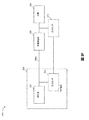
図1は、創傷くぼみ110であって、創傷カバー120によって封止された創傷くぼみの内部に置かれた創傷充填材130を備える、陰性のまたは低減された圧力創傷治療(またはTNP)システム100の実施形態を示す。創傷カバー120と組み合わされた創傷充填材130は、創傷被覆材として言及され得る。単一または複数の内腔管または導管140は、創傷カバー120と、減圧圧力を供給するように構成されるポンプアセンブリ150とを接続する。創傷カバー120は、創傷くぼみ110に流体連通することができる。図1に示される実施形態のような本明細書で開示されるいくつかのシステムの実施形態において、ポンプアセンブリは、キャニスターレスポンプアセンブリ(滲出液が、創傷被覆材に集められる、または別の位置に集めるために管140を介して運ばれることを意味する)であることができる。しかし、本明細書で開示されるいくつかのポンプアセンブリの実施形態は、キャニスターを含むまたは支持するように構成され得る。追加的に、本明細書で開示されるいくつかのシステムの実施形態において、いくつかのポンプアセンブリの実施形態は、被覆材に取り付けられ、もしくは被覆材によって支持され、または被覆材に隣接することができる。
Negative Pressure System FIG. 1 is a negative or reduced pressure wound therapy (or TNP) comprising a wound well 110, the
創傷充填材130は、例えば、親水性または疎水性発泡体、ガーゼ、膨張可能なバッグ等の任意の適切なタイプであることができる。創傷充填材130は、それが実質的にくぼみを充填するように、創傷くぼみ110に適合することができる。創傷カバー120は、創傷くぼみ110を覆う実質的に流体不浸透性のシールを提供することができる。創傷カバー120は、上部側面および下部側面を有することができ、下部側面は、創傷くぼみ110を粘着的に(または任意のその他の適切な手法において)封止する。本明細書で開示される導管140もしくは内腔またはいくつかのその他の導管もしくは内腔は、ポリウレタン、PVC、ナイロン、ポリエチレン、シリコーン、または任意のその他の適切な材料から形成され得る。
The
創傷カバー120の一部の実施形態は、導管140の端を受けるように構成される、ポート(図示せず)を有することができる。例えば、ポートは、Smith&Nephewから入手可能なRenays Soft Portであることができる。その他の実施形態では、導管140は、別のやり方では、創傷くぼみ内に所望のレベルの減圧圧力を維持するように、減圧圧力を創傷くぼみ110に供給するために創傷カバー120を通り抜けるまたはその下にあることができる。導管140は、ポンプアセンブリ150によって提供される減圧圧力を創傷くぼみ110に供給するように、ポンプアセンブリ150と創傷カバー120との間に少なくとも実質的に密封された流体流経路を提供するように構成される、任意の適切な物品であることができる。
Some embodiments of the
創傷カバー120および創傷充填材130は、単一な物品または一体型の単一なユニットとして提供され得る。一部の実施形態では、創傷充填材が提供されずに、創傷カバーがそれ自体として創傷被覆材とみなされてもよい。ついで、創傷被覆材は、導管140を介して、ポンプアセンブリ150といった陰圧源に接続され得る。ポンプアセンブリ150は小形化され、持ち運び可能とすることができるが、より大きな従来のそのようなポンプがまた使用されてもよい。
創傷カバー120は、治療される創傷部位の上に置かれ得る。創傷カバー120は、創傷部位を覆う実質的に密封されたくぼみまたはエンクロージャを形成することができる。一部の実施形態では、創傷カバー120は、過剰流体の蒸発を可能にする高い水蒸気浸透性を持つフィルムを有するように構成されることができ、また創傷滲出液を安全に吸収するためにその中に含まれる超吸収性材料を有することができる。本明細書全体を通して、創傷に関して言及することが理解されるであろう。この点において、創傷という用語は広く解釈され、皮膚が断裂、切開、もしくは穿孔される、または外傷によって挫傷が引き起こされる開放創および閉鎖創、あるいは患者の皮膚における任意の他の表面もしくは他の状態または欠陥、あるいは減圧治療によって利益を得る他のものを包含することを理解されたい。よって、創傷は、流体が生成されることもされないこともある、組織の任意の損傷領域として広く定義される。そのような創傷の例としては、急性創傷、慢性創傷、外科切開およびその他の切開、亜急性創傷および裂開創傷、外傷性創傷、フラップおよび皮膚移植片、裂傷、擦傷、挫傷、火傷、糖尿病性潰瘍、褥瘡性潰瘍、ストーマ、外科創傷、外傷性潰瘍および静脈性潰瘍などが挙げられるが、それらに限定されない。本明細書に記載のTNPシステムの構成要素は、少量の創傷滲出液を滲出する切開創傷に特に適し得る。
システムの一部の実施形態は、滲出液キャニスターを使用することなく動作するように設計される。一部の実施形態は、滲出液キャニスターを支持するように構成され得る。一部の実施形態では、管材料140がポンプアセンブリ150から迅速にかつ容易に取り除かれ得るようにポンプアセンブリ150および管材料140を構成することは、必要な場合、被覆材またはポンプを交換するプロセスを容易にする、または改善することができる。本明細書で開示されるいくつかのポンプの実施形態は、管材料とポンプとの間の任意の適切な接続を有するように構成され得る。
Some embodiments of the system are designed to operate without the use of an exudate canister. Some embodiments may be configured to support the exudate canister. In some embodiments, configuring the
ポンプアセンブリ150は、一部の実装において、約−80mmHg、または約−20mmHg〜200mmHgの陰圧を供給するように構成され得る。これらの圧力は、正常な大気圧に対する相対値であり、つまり、−200mmHgは、実際に則した用語において、約560mmHgであり得ることに留意されたい。圧力範囲は約−40mmHgから−150mmHgの間であり得る。代替として、最高−75mmHg、最高−80mmHgまたは−80mmHgを超える圧力範囲が使用され得る。また、−75mmHgを下回る圧力範囲が使用され得る。代替として、およそ−100mmHgまたはさらに150mmHgより上の圧力範囲が、ポンプアセンブリ150により供給され得る。
動作時に、創傷充填材130は、創傷くぼみ110内に挿入され、創傷カバー120は、創傷くぼみ110を密封するように置かれる。ポンプアセンブリ150は、創傷充填材130を介して創傷くぼみ110に送られる陰圧源を創傷カバー120に提供する。流体(例えば、創傷滲出液)は、導管140を通して引き出され、キャニスター内に貯蔵され得る。一部の実施形態では、流体は、創傷充填材130または1つ以上の吸収性の層(図示せず)によって吸収される。
In operation, the
本出願のポンプアセンブリおよびその他の実施形態とともに利用され得る創傷被覆材は、Smith&Nephewから入手可能なRenasys−F、Renasys−G、Renasys ABおよびPico被覆材を含む。本出願のポンプアセンブリおよびその他の実施形態とともに使用され得る陰圧創傷療法システムのこうした創傷被覆材およびその他の構成要素のさらなる説明は、米国特許公開第2011/0213287号、第2011/0282309号、第2012/0116334号、第2012/0136325号および第2013/0110058号において見出され、それらの全体が参照により援用される。その他の実施形態では、その他の適切な創傷被覆材が利用され得る。 Wound dressings that may be utilized with the pump assembly and other embodiments of the present application include Renasys-F, Renasys-G, Renasys AB and Pico dressings available from Smith & Nephew. Further description of such wound dressings and other components of a negative pressure wound therapy system that may be used with the pump assembly and other embodiments of the present application can be found in US Patent Publication Nos. 2011/0213287, 2011/0282309, No. 2012/0116334, 2012/0136325 and 2013/0110058, which are incorporated by reference in their entirety. In other embodiments, other suitable wound dressings may be utilized.
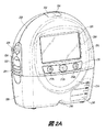
図2Aは、一部の実施形態によるポンプアセンブリ230およびキャニスター220の前方図を示す。示されるように、ポンプアセンブリ230とキャニスターが接続されて、それにより、陰圧創傷療法デバイスを形成する。ポンプアセンブリ230は、一部の実施形態におけるポンプアセンブリ150と類似し、またはそれと同一であり得る。
FIG. 2A shows a front view of the
ポンプアセンブリ230は、アラームを示すように構成される視覚的指標202およびTNPシステムの状態を示すように構成される視覚的指標204などの1つ以上の指標を含む。指標202および204は、通常のまたは適切な動作状態、ポンプ停止、ポンプまたは停電に供給される電力、創傷カバーまたは流れ経路内の漏れの検出、吸引閉塞、またはいくつかのその他の同様のまたは適切な状態またはそれらの組み合わせをユーザーに警告することを含む、システムの様々な動作または停止状態を患者または医療提供者などのユーザーに警告するように構成され得る。ポンプアセンブリ230は、追加的な指標を備えることができる。ポンプアセンブリは、単一な指標または複数の指標を使用することができる。任意の適切な指標は、例えば、視覚的な、音声的な、触覚的な指標等として使用され得る。指標202は、例えば、キャニスター充填、低電力、導管140の分離、創傷シール120におけるシール破壊等の警告状態を示すように構成され得る。指標202は、ユーザーの注意を引くために赤のせん光を表示するように構成され得る。指標204は、例えば、療法送達は正常である、漏れが検出された等のTNPシステムの状態を示すように構成され得る。指標204は、例えば、緑、黄などの1つ以上の異なる色の光を表示するように構成され得る。例えば、緑色の光は、TNPシステムが適切に動作している時に放出されてもよく、黄色の光は、警告を示すために放出され得る。
The
ポンプアセンブリ230は、ポンプアセンブリのケースに形成されたくぼみ208に取り付けられる、ディスプレイまたはスクリーン206を含む。ディスプレイ206は、タッチスクリーンディスプレイであることができる。ディスプレイ206は、取扱い説明ビデオなどの視聴覚(AV)コンテンツの再生を支持することができる。以下で説明されるように、ディスプレイ206は、いくつかのスクリーンまたはグラフィカルユーザーインタフェース(GUI)がTNPシステムの動作を構成する、制御する、および監視するように構成され得る。ポンプアセンブリ230は、ポンプアセンブリのケースに形成されたグリップ部分210を含む。グリップ部分210は、例えば、キャニスター220の取り外しの間などに、ユーザーがポンプアセンブリ230を保持することを支持するように構成され得る。キャニスター220は、例えば、キャニスター220が流体で充填された時などに、別のキャニスターと取り替えられ得る。
ポンプアセンブリ230は、ユーザーがTNPシステムの動作を操作し、および監視することを可能にするように構成される、1つ以上のキーまたはボタンを含む。示されるように、これには、ボタン212a、212bおよび212c(集合的にボタン212として言及される)が含まれる。ボタン212aは、ポンプアセンブリ230の電源を入れる/切るための電源ボタンとして構成され得る。ボタン212bは、陰圧療法の供給のためのプレイ/ポーズボタンとして構成され得る。例えば、ボタン212bを押すことにより、療法を開始することができ、その後ボタン212bを押すことにより、療法を停止または終了することができる。ボタン212cは、ディスプレイ206またはボタン212をロックするように構成され得る。例えば、ボタン212cは、ユーザーが故意でなく療法の供給を変えることがないように押され得る。ボタン212cは、制御をアンロックするために押下され得る。その他の実施形態では、追加的なボタンが、用いられてもよく、または示したボタン212a、212bまたは212cのうち1つ以上が、省かれてもよい。複数のキーの押下または連続的なキーの押下は、ポンプアセンブリ230を動作させるために使用され得る。
ポンプアセンブリ230は、カバーに形成される1つ以上のラッチ凹部222を含む。例示の実施形態では、2つのラッチ凹部222は、ポンプアセンブリ230の側部に形成され得る。ラッチ凹部222は、1つ以上のキャニスターラッチ221を使用してキャニスター220の取付けおよび分離を可能にするように構成され得る。ポンプアセンブリ230は、創傷くぼみ110から取り除かれる空気が漏れ出ることを可能にするための空気出口224を備える。ポンプアセンブリに入る空気は、抗菌フィルタなどの1つ以上の適切なフィルタを通り抜けることができる。これは、ポンプアセンブリの再利用性を維持することができる。ポンプアセンブリ230は、ポンプアセンブリ230に携帯ストラップを接続するための、または受け台を取り付けるための1つ以上のストラップ取付け部226を含む。例示の実施形態では、2つのストラップ取付け部226は、ポンプアセンブリ230の側部に形成され得る。一部の実施形態では、種々のこれらの特徴は省かれ、または種々の追加的な特徴がポンプアセンブリ230に加えられる。
キャニスター220は、創傷くぼみ110から取り除かれる流体(例えば、滲出液)を保持するように構成される。キャニスター220は、キャニスターをポンプアセンブリ230に取り付けるための1つ以上のラッチ221を含む。例示の実施形態では、キャニスター220は、キャニスターの側部に2つのラッチ221を備える。キャニスター220の外部は、キャニスターが実質的に不透明であり、またキャニスターの中身が平面視で実質的に隠されるように、つや消しプラスチックから形成され得る。キャニスター220は、キャニスターのケースに形成されるグリップ部分214を備える。グリップ部分214は、例えば、装置230からのキャニスターの取り外しの間などに、ユーザーがポンプアセンブリ220を保持することを可能にするように構成され得る。キャニスター220は、実質的に透明な窓216を含み、それはまた、量の目盛りを含むことができる。例えば、示される300mLのキャニスター220は、50mL、100mL、150mL、200mL、250mLおよび300mLの目盛りを含む。キャニスターのその他の実施形態は、異なる量の流体を保持することができ、異なる目盛り尺度を含むことができる。例えば、キャニスターは、800mLのキャニスターであることができる。キャニスター220は、導管140に接続するための管状のチャネル218を備える。一部の実施形態では、グリップ部分214などの種々のこれらの特徴は省かれ、または種々の追加的な特徴がキャニスター220に加えられる。いくつかの開示されるキャニスターは、凝固剤を含んでもよく、または凝固剤を省いてもよい。
The
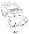
図2Bは、一部の実施形態によるポンプアセンブリ230およびキャニスター220の背面図を示す。ポンプアセンブリ230は、音を生成するためのスピーカーポート232を備える。ポンプアセンブリ230は、フィルタアクセスドア234を含み、そのドアは、アクセスドア234を取り外し、抗菌または臭気フィルタなどの1つ以上のフィルタと連通し、それを取り替えるためのねじを有する。ポンプアセンブリ230は、ポンプアセンブリのケースに形成されたグリップ部分236を含む。グリップ部分236は、例えば、キャニスター220の取り外しの間などに、ユーザーがポンプアセンブリ230を保持することを可能にするように構成され得る。ポンプアセンブリ230は、表面上にポンプアセンブリ230を配置するためのねじカバーまたは足部またはプロテクターとして構成される、1つ以上のカバー238を含む。カバー230は、ゴム、シリコーンまたは任意のその他の適切な材料で形成され得る。ポンプアセンブリ230は、ポンプアセンブリの内部バッテリーを充電および再充電するための電源ジャック239を備える。電源ジャック239は、直流(DC)ジャックであることができる。一部の実施形態では、ポンプアセンブリは、電源ジャックが必要ないように、バッテリーなどの使い捨て可能な電源を備え得る。
FIG. 2B shows a rear view of the
キャニスター220は、表面上にキャニスターを配置するための1つ以上の足部244を含む。足部244は、ゴム、シリコーンまたは任意のその他の適切な材料で形成されてもよく、キャニスター220が表面上に配置された時に安定した状態を保つように適切な角度に角度付けられてもよい。キャニスター220は、1つ以上の管がデバイスの前部へと抜け出ることを可能にするように構成される、管取付けレリーフ246を備える。キャニスター220は、キャニスターが表面上に配置された時にキャニスターを支持するためのスタンドまたはキックスタンド248を含む。以下で説明されるように、キックスタンド248は、開位置と閉位置との間で旋回することができる。閉位置において、キックスタンド248は、キャニスター220にラッチされ得る。一部の実施形態では、キックスタンド248は、プラスチックなどの不透明材料から作られ得る。その他の実施形態では、キックスタンド248は、透明材料から作られ得る。キックスタンド248は、キックスタンドに形成されるグリップ部分242を含む。グリップ部分242は、ユーザーがキックスタンド248を閉位置に位置付けることを可能にするように構成され得る。キックスタンド248は、穴249を含み、それは、ユーザーがキックスタンドを開位置に位置付けることを可能にする。穴249は、ユーザーが指を用いてキックスタンドを伸ばすことが可能となるようにサイズ設定され得る。
図2Cは、一部の実施形態によるキャニスター220から分離されたポンプアセンブリ230を示す。ポンプアセンブリ230は、真空ポンプがそれを通じてキャニスター220に陰圧を伝達する、真空アタッチメント、コネクターまたは入口252を含む。ポンプアセンブリは、入口252を介して創傷からの気体などの流体を吸い出す。ポンプアセンブリ230は、1つ以上のUSBポートへのアクセスを可能にするように構成される、USBアクセスドア256を備える。一部の実施形態では、USBアクセスドアが省かれ、またUSBポートはドア234を通じてアクセスされる。ポンプアセンブリ230は、例えば、SD、コンパクトディスク(CD)、DVD、ファイアワイア、サンダーボルト、PCIエクスプレスなどの追加的なシリアル、パラレル、またはハイブリッドデータ転送インターフェースへのアクセスを可能にするように構成される、追加的なアクセスドアを含むことができる。その他の実施形態では、これらの追加的なポートのうち1つ以上は、ドア234を通じてアクセスされる。
FIG. 2C shows the
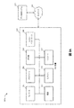
図3Aは、TNP装置310および遠隔データ処理システム320を含む、陰圧療法システム300Aの構成要素を示す。TNP装置310は、流体流路を介してTNP装置310と流体連通する創傷被覆材を使用して創傷を治療するように使用され得る。TNP装置310には、相互に電気的通信するように構成された、コントローラ311、メモリデバイス312、陰圧源313と、ユーザーインターフェース314と、電源315と、圧力センサ316と、トランシーバ317とが含まれ得る。電源315は、TNP装置310の1つ以上の構成要素に電力を供給することができる。TNP装置310は、本明細書で説明したような、またはその全体が参照により援用される米国特許公開第2016/0136339号および第2016/0184496号に記載のものと同様の圧力レベルで、また制御手法を使用して動作することができる。TNP装置310は、一部の実施形態におけるポンプアセンブリ150と類似し、またはそれと同一であり得る。
FIG. 3A shows the components of negative
コントローラ311は、メモリデバイス312に格納された命令に少なくとも従って、TNP装置310の1つ以上の他の構成要素の動作を制御することができる。例えば、コントローラ311は、陰圧源313の動作およびそれによる陰圧の供給を制御することができる。陰圧源313には、限定されないが、ロータリーダイヤフラムポンプもしくは他のダイヤフラムポンプ、圧電ポンプ、蠕動ポンプ、ピストンポンプ、ロータリーベーンポンプ、液封式ポンプ、スクロールポンプ、圧電変換器によって動作するダイヤフラムポンプ、または他の任意の好適なポンプもしくはマイクロポンプ、あるいは上記のものの任意の組み合わせなどのポンプが含まれ得る。
The
ユーザーインターフェース314は、ユーザー入力を受信するか、またはユーザー出力を患者または介護者に提供する1つ以上の要素を含み得る。ユーザー入力を受信する1つ以上の要素は、ボタン、スイッチ、ダイヤル、またはタッチスクリーンなどを含むことができる。ユーザーインターフェース314は、例えば、療法使用のデータ、準拠しない使用のデータまたは療法使用の準拠しない使用に対するデータの比較を反映するレポートまたはその他の情報を生成し、表示するために使用され得る。別の実施例として、ユーザーインターフェース314は、患者参照番号または別の一意的識別子を提供するユーザー入力を受信してもよく、TNP装置310は、次に、患者によって使用のために作動されてもよく、本明細書で説明したように集められ、かつ記憶されたデータは、特定の患者を監視する使用のために患者参照番号と関係付けられてもよい。
圧力センサ316は、(i)図3Bに示されるような陰圧源313と創傷被覆材とに接続している流体流路の圧力、(ii)図3Cに示されるような創傷被覆材での圧力、または(iii)図3Dに示されるような陰圧源313での、または陰圧源313内の圧力などの、創傷被覆材の下側の圧力を監視するために使用され得る。陰圧源313が陰圧を与えるのに従って、陰圧源313は、流体流路を通じて伝搬され、圧力センサ316によって検出される圧力パルスを生成し得る。これらの圧力パルスは、圧力センサ316からの信号の大きさまたは周波数における変化またはバウンスとして示され得る。
The
コントローラ311は、圧力センサ316によって出力された信号を分析して、それにより、流体流路内の圧力を決定することができる。コントローラ311は、例えば、デジタル信号プロセッサを用いるなどの、時間領域または周波数領域算出を含む1つ以上の手法を使用して信号を調べ得る。
The
TNP装置310のコントローラ311またはその他の回路は、ノイズをフィルタリングし、次にフィルタリングした1つ以上の信号を動的に増幅することによって、圧力センサ316によって出力された1つ以上の信号を処理し得る。動的な増幅は、フィルタリングすることなく実行されてもよい。これは、本明細書に記載の特徴が小さい創傷または弱い圧力信号に適用されることを可能にし得る。例えば、増幅は、ソフトウエアまたはハードウエアによって制御され得る、プログラム可能な利得増幅器によって実行され得る。
The
圧力センサ316による圧力の検出は、一部の実例において、陰圧源313によって供給される真空レベルを増大するまたは減少すること、陰圧源313を停止すること、陰圧源313の動作速度を変えること、陰圧源313のリズムを変えること、同じのものの組み合わせ等などの、陰圧源313の1つ以上の設定を変えることによって、向上され得る。コントローラ311は、例えば、1つ以上の設定の調節を自動的に管理することができる。
Detection of pressure by the
一部の実装では、圧力センサ316は、別の圧力センサと組み合わせて用いられてもよく、その結果、例えば、図3Eに示されるように、流体流路に位置付けられる、または流体流路に流体接続される少なくとも2つの圧力センサが、異なる圧力の測定を行うことを可能にする。例えば、第1の圧力センサは、創傷の上流に(例えば、陰圧源313Cの入口に、またはその近くに)位置付けられてもよく、第2の圧力センサは、創傷におけるもしくは創傷の近くの、またはキャニスターにおけるもしくはキャニスターの近くの圧力を検出するように位置付けられてもよい。この構成は、さらに、陰圧源313を創傷に接続する第1の流体流路、TNP装置310を創傷に接続する1つ以上の内腔を含み、また第2の圧力センサがそれを通じて創傷におけるもしくは創傷の近くの、またはキャニスターにおけるもしくはキャニスターの近くの圧力を監視することができる、第2の流体流路を形成する1つ以上の内腔を組み込むことによって達成され得る。第1および第2の流体流路は、相互に流体的に分離され得る。少なくとも2つの圧力センサが使用される場合、第1および第2の流体流路内の圧力変化のレート(例えば、ピーク間の圧力または最大圧力における)が定められてもよく、第1の圧力センサと第2の圧力センサとの間で検出された圧力差が定められてもよい。これらの値は、例えば、第1の流体流路または第2の流体流路における、漏れ、閉塞、キャニスター充填状態、血液の存在などの種々の動作状態を検出するために個々に、または一緒に使用され得る。一部の実装では、複数の冗長圧力センサが、圧力センサのうち1つ以上の故障に対して保護するために提供され得る。
In some implementations,
トランシーバ317は、ネットワーク330を介してデータ処理システム320と通信するように使用され得る。トランシーバ317は、例えば、TNP装置310によって管理された療法プログラムに対するアラーム、測定された圧力または変化のようなデバイス使用データをデータ処理システム320に送信することができる。ネットワーク330は、セルラー方式通信ネットワークのような無線通信ネットワークなどの通信ネットワークであることができる。メモリデバイス312は、トランシーバ317によって送信され得るデバイス使用データを記憶するように使用され得る。
データ処理システム320は、一部の実装では、トランシーバ317から受信した圧力データを分析して、受信した圧力データが、TNP装置310に関して説明したような分析手法を使用することなどの患者への使用における陰圧源313を示すものであるかどうかを決定することができる。データ処理システム320は、例えば、療法使用のデータ、準拠しない使用のデータまたは療法使用の準拠しない使用に対するデータの比較を反映するレポートまたはその他の情報を生成し、表示することができる。一例では、データ処理システム320のユーザーは、患者参照番号またはTNP装置と関連するTNP装置番号を入力してもよく、データ処理システム320は、次に、患者参照番号またはTNP装置番号に関する療法使用のデータまたは準拠しない使用のデータなどのデータを提供する、または表示することができる。
図3Bは、図3AのTNP装置310のほか、第1の流体流路340A、創傷被覆材350および創傷360を含む、陰圧療法システム300Bを示す。TNP装置310は、第1の流体流路340Aを介して陰圧源313と流体連通する創傷被覆材350を使用して創傷360を治療するように使用され得る。特に、図3Bは、第1の流体流路340A内の圧力を測定するために、圧力センサ316が、例えば、TNP装置310の入口においてまたはその近くにおいて、第1の流体流路340Aに位置付けられ得ることを示す。
FIG. 3B shows a negative
図3Cは、圧力センサ316が、その代わりに、創傷被覆材350が創傷360に結合された時の創傷被覆材350の下側の圧力などの創傷被覆材350における、またはその近くの圧力を測定するように位置付けられ得る点において陰圧療法システム300Bと異なる、陰圧療法システム300Cを示す。
FIG. 3C shows that the
図3Dは、圧力センサ316が、その代わりに、陰圧源313における圧力を測定するように位置付けられ得る点において陰圧療法システム300Bと異なる、陰圧療法システム300Dを示す。一例では、圧力センサ316は、陰圧源313の一部分であり、かつ陰圧源313内にあり、それにより、陰圧源313によって生成された圧力を測定することができる。別の実施例では、圧力センサ316は、陰圧源313から分離され、陰圧源313の入口における、またはその近くの圧力を測定するように位置付けられ得る。
FIG. 3D shows negative
図3Eは、陰圧療法システム300Eが、第2の流体流路340Bをさらに含み、また圧力センサ316が、差圧センサであり、または2つの圧力センサを含むことができる点において陰圧療法システム300Bと異なる、陰圧療法システム300Eを示す。圧力センサ316が2つの圧力センサを含み得る場合、圧力センサ316の2つの圧力センサのうちの一方は、第1の流体流路340Aに位置付けられて、第1の流体流路340A内の圧力を測定することができ、圧力センサ316の2つの圧力センサのうちの他方は、第2の流体流路340Bに位置付けられて、第2の流体流路340B内の圧力を測定することができる。圧力センサ316が差圧センサであり得る場合、圧力センサ316は、第1の流体流路340Aおよび第2の流体流路340Bに流体接続され得る。第1の流体流路340Aは、したがって、陰圧源313によって使用されて、創傷被覆材350に陰圧を与えることができ、第2の流体流路340Bは、主として圧力センサ316によって使用されて、創傷被覆材360の下などの創傷被覆材350における、またはその近くの圧力を測定することができる。圧力センサ316は、陰圧源313によって供給される圧力と、創傷被覆材350における、またはその近くの圧力との間の差圧測定を実行するためにTNP装置310により使用され得る。
FIG. 3E shows that negative
図3Fは、陰圧療法システム300Fが、創傷被覆材350が創傷360に結合された時の創傷被覆材350の下側の圧力などの創傷被覆材350における、またはその近くの圧力を測定するように位置付けられる追加的な圧力センサ370をさらに含むことができる点において陰圧療法システム300Bと異なる、陰圧療法システム300Fを示す。追加的な圧力センサ370は、創傷被覆材350で測定された圧力に応答して、信号を生成し、TNP装置310にその信号を出力することができる。圧力センサ316および追加的な圧力センサ370は、したがって、陰圧源313によって供給される圧力と、創傷被覆材350における、またはその近くの圧力との間の差圧測定を実行するためにTNP装置310により使用され得る。
FIG. 3F shows that the negative
図3Gは、キャニスター380が、第1の流体流路340Aにおいて、陰圧源313と創傷被覆材350との間に結合され得る点において陰圧療法システム300Bと異なる、陰圧療法システム300Gを示す。キャニスター380は、創傷360から取り出された滲出液を集めることができる。図3C〜図3Fの実施例は、一部の実装において、キャニスター380をさらに含むように同様に変更され得る。
FIG. 3G shows negative pressure therapy system 300G different from negative
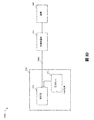
図4は、TNP装置410およびセンサ420A、420B〜420Nを含む陰圧療法システム400を示す。センサ420A、420B〜420Nは、有利には、一定の実施形態において、患者へのTNP装置410の結合またはその使用を確実にするために使用され得る。TNP装置410は、一部の実施形態におけるTNP装置310と類似し、またはそれと同一であり得る。センサ420A、420B〜420Nのうちの1つは、一部の実施形態における圧力センサ316と類似し、またはそれと同一であり得る。センサ420A、420B〜420Nのうちの1つは、一部の実施形態における圧力センサ370と類似し、またはそれと同一であり得る。
FIG. 4 shows a negative
センサ420A、420B〜420Nは、患者の接触部位430A、430B〜430Nからそれぞれ検出することができ、または患者に応答することができる。センサ420Aは、例えば、接触部位430Aから検出することができ、センサ420Bは接触部位430Bから検出することができ、一方で、センサ420Nは接触部位430Nから検出することができる。接触部位430A、430B〜430Nは、患者の組織部位(例えば、患者の創傷、肢または頭における患者の内部または外部組織)、患者に取り付けられた物品(例えば、衣類または宝石類)、またはTNP装置410もしくはキャニスターのような関連する構成要素の一部分を含むことができる。センサ420A、420B〜420Nのうち1つ以上は、創傷被覆材の一部分として組み込まれてもよく、または創傷被覆材に結合するように構成されてもよい。
センサ420A、420B〜420Nは、例えば、圧力センサ、音響センサ、化学的なセンサ、電流センサ、電位センサ、インピーダンスセンサ、磁気センサ、光学センサ、色センサ、圧力センサ、圧電センサ、温度計、熱センサ、近接センサ、バイオセンサ、歪みゲージ、同様の組み合わせ等のうち1つ以上を含むことができる。センサ420A、420B〜420Nは、一部の実装において、異なる位置で検出するように配置される同様のセンサ、または異なるセンサであることができる。
The
センサ420A、420B〜420Nのそれぞれは、無線または有線通信を介して、対応する監視した接触部位430A、430B〜430Nのうちの1つに応答する1つ以上の信号をTNP装置410に送信することができる。1つ以上の信号は、例えば、患者の生理的状態または患者の動きに応答することができる。次に、TNP装置410は、1つ以上の信号を処理して、2つ以上のセンサ420A、420B〜420Nからの1つ以上の信号が、TNP装置410または創傷被覆材のような関連する構成要素が患者に結合されている、または患者に準拠した使用状態にあることを示すかどうかを決定することができる。TNP装置410は、例えば、センサ420A、420B〜420Nのうちの2つ以上のそれぞれまたは少なくとも1つのサブセットが、生理学的に許容される信号(例えば、患者の呼吸、脈拍または動きのような患者の活動に応答する信号)であって、患者への成功した結合またはTNP装置410と患者の関連付けを示す信号を、TNP装置410に提供するかどうかを決定することができる。
Each of the
創傷結合検出
図5は、図1のポンプアセンブリ150、図2A〜図2Cのポンプアセンブリ230、図3AのTNP装置310、またはあらかじめその全体が参照によって本明細書に援用された米国特許公開第2016/0136339号および第2016/0184496号に記載のものと同様のその他のポンプアセンブリなどのデバイスによる創傷結合検出プロセス500を示す。便宜上、創傷結合検出プロセス500が図3AのTNP装置310との関連において説明されるが、代わりに、本明細書に記載の他のシステムで、または示されていない他のシステムによって実行される場合もある。
Wound Binding Detection FIG. 5 is the
創傷結合検出プロセス500は、TNP装置310が、TNP装置310に結合された創傷被覆材が患者の創傷に結合されているかどうかを自動的に決定することを可能にし得る。TNP装置310は、有利には、一定の実施形態において、創傷被覆材が創傷に結合されていると決定した時に第1の表示を、または創傷被覆材が創傷に結合されていないと決定した時に第1の表示とは異なる第2の表示を出力することができる。
The wound binding
ブロック502では、プロセス500は、圧力データを受信することができる。例えば、コントローラ311は、陰圧源313を創傷被覆材に結合する流体流路で測定された圧力の大きさを示す圧力データを受信することができる。圧力は、例えば、本明細書において、またはあらかじめその全体が参照によって本明細書に援用された米国特許公開第2016/0136339号および第2016/0184496号において説明されるような測定手法を用いて、圧力センサ316によって測定され得る。圧力センサ316は、有線または無線を介してコントローラ311に情報を伝達することができる。一定の実装では、圧力センサ316は、創傷にまたはその近くに位置付けられて、無線でコントローラ311に情報を伝達することができる。一部の実施形態では、圧力センサデータは、例えば、0.5秒、1秒、3秒などの継続時間にわたって測定された1つ以上の圧力の大きさを含む。
At
ブロック504では、プロセス500は、被覆材が創傷に結合されているかどうかを決定することができる。例えば、コントローラ311は、ある期間にわたる大きさの変化などの圧力データから、創傷被覆材が患者の創傷に結合されているかどうかを決定することができる。
At
一例では、コントローラ311は、ある期間にわたる大きさの変化の不規則性の測定を1つ以上の閾値と比較して、創傷被覆材が創傷に結合されているかどうかを決定することができる(一部の実例では、誤った圧力読取り、ノイズなどによる誤検知を防ぐために複数回の比較を実行する)。不規則性の測定は、少なくとも1秒、10秒、30秒、1分または5分の継続時間にわたる大きさの変化に応答することができる。コントローラ311は、ある期間にわたる大きさに基づく統計動作、トレンディング動作、フィルタリング動作、累積合計動作、またはローパスフィルタリング動作を実行して、不規則性の測定を生成することができる。コントローラ311は、不規則性の測定が、混沌とした状態に対応する閾値を満たすこと、または定常状態に対応する閾値を満たさないことの決定に応じて、創傷被覆材が創傷に結合されていることを決定することができる。一方では、コントローラ311は、不規則性の測定が、混沌とした状態に対応する閾値を満たさないこと、または定常状態に対応する閾値を満たすことの決定に応じて、創傷被覆材が創傷に結合されていないことを決定することができる。不規則性の測定と比較される1つ以上の閾値は、さらに、経時的に変わることができ(例えば、患者を治療するために自動的に調節される)、またはTNP装置310に関する動作状態に応答して設定されてもよく(例えば、バックグラウンドノイズに多少敏感になるように調節される)、または患者の健康に関するニーズ(例えば、患者の創傷の大きさ、性別または患者の年齢に応じて調節される)に応答して設定されてもよい。
In one example, the
さらに別の実施例では、コントローラ311は、ある期間にわたる大きさを1つ以上の圧力パターン(メモリデバイス312に記憶されている1つのパターンなど)と比較して、創傷被覆材が創傷に結合されているかどうかを決定することができる。1つの圧力パターンは、例えば、創傷被覆材が創傷に結合されている時の流体流路内の圧力を示すことができ、別の異なる圧力パターンは、創傷被覆材が創傷に結合されていない時の流体流路内の圧力を示すことができる。1つ以上の圧力パターンに関連する経時的な大きさの類似性の度合いは、創傷被覆材が創傷に結合されているかどうかを反映するように経時的な大きさを割り当てるために使用され得る。
In yet another embodiment, the
ブロック506では、プロセス500は第1の表示を出力することができる。例えば、創傷被覆材が創傷に結合されていることの決定に応じて、コントローラ311は、創傷被覆材が創傷に結合されていることを示す第1の表示を出力することができる。第1の表示は、一部の実例において、TNP装置310の準拠した使用を示すことができる。第1の表示は、例えば、メモリデバイス312への記憶のために第1の表示を出力すること、トランシーバ317を介してデータ処理システム320に第1の表示を送信すること、ユーザーインターフェース314を介するユーザーへの呈示のために第1の表示を出力すること、またはTNP装置310のデバイス使用データと関連して第1の表示を記憶することのうち1つ以上のために出力され得る。第1の表示の出力は、例えば、陰圧源313の連続的な動作を可能にするために、TNP装置310の動作を追加的に制御することができる。
At
ブロック508では、プロセス500は第2の表示を出力することができる。例えば、創傷被覆材が創傷に結合されていないことの決定に応じて、コントローラ311は、創傷被覆材が創傷に結合されていないことを示す第2の表示を出力することができる。第2の表示は、一部の実例において、TNP装置310の準拠しない使用を示すことができる。第2の表示は、例えば、メモリデバイス312への記憶のために第2の表示を出力すること、トランシーバ317を介してデータ処理システム320に第2の表示を送信すること、ユーザーインターフェース314を介するユーザーへの呈示のために第2の表示を出力すること、またはTNP装置310のデバイス使用データと関連して第2の表示を記憶することのうち1つ以上のために出力され得る。第2の表示の出力は、TNP装置310が準拠しない様式で使用され得るので、例えば、陰圧源313の動作を停止させるために、TNP装置310の動作を追加的に制御することができる。
At
プロセス500は、TNP装置310が準拠したまたは準拠しない様式で使用され得るかどうかに関する追加的な情報または確実性を提供するために、例えば、図4に関して説明したような別のセンサからのデータを調べることができる。例えば、TNP装置310に関連する別のセンサが患者の脈拍または呼吸を反映する信号を検出する場合、TNP装置310は、TNP装置310が準拠しない様式ではなく準拠した様式で使用されていることのさらなる確実性および情報を有し得る。
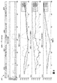
図6は、TNP装置310などのTNP装置の陰圧源が患者の創傷に使用されているTNPシステムに関する、例示的な時間に対する圧力の曲線600を示す。図6から分かるように、陰圧源が一定の時間作動すると、時点T1において、流体流路内の圧力の大きさは、概して目標圧力レベルの辺りを変動する。しかし、流体流路内の圧力の大きさは、いくつかの理由により、時点T1〜T2において、実質的に混沌としており、予測できない状態であり得る。患者は、位置、呼吸または脈拍の物理的な調節のために連続的に移動することができ、そのため、例えば、創傷、被覆材シールなどの幾何学的配置に影響を与える。結果として、創傷の体積は、圧力の大きさの変化をもたらし得る軽微な変更を連続的に受け得る。さらに、創傷は、それが流体流路に入ることに基づいて気体量の減少を引き起こし得る、滲出液を生成し得る。気体量は、システム内の圧縮可能な量を表すことができるので、この圧縮可能な量は、陰圧源および患者の動きによって生成される圧力スパイクに対するダンパーとしての役目を果たすことができ、その結果、圧力スパイクは、減少したダンピングによって徐々に大きくなる。さらに、液体は、創傷被覆材から出て、スラグにおける流体流路を通じて移動することができ、これらのスラグは、圧力スパイクに影響(例えば、大きさまたは周波数の増加)を与えることができる。全体的に、これは結果として、圧力読取りにおける比較的相当量のノイズであり得る。図6によって示される圧力の大きさは、したがって、時点T1〜T2において、定常状態ではなく混沌とした状態の反映であり得る。さらに、または別の方法として、周波数などの圧力のその他の特性は、変化として監視され得る。例えば、時点T1〜T2において、圧力信号の周波数は、継続時間614よりも継続時間612にわたって小さい。
FIG. 6 shows an exemplary time-to-
一実装では、TNP装置310は、上記の段落で説明されたノイズを監視して、陰圧源が患者に接続されているかどうかを決定することができる。したがって、TNP装置11は、例えば、(i)患者データまたは(ii)デバイス誤用のいずれかとして事象の使用データおよびログにフラグを付けることができる。TNP装置310は、一部の実例において、累積和(Cusum)またはローパスフィルタリングなどの統計的な技法、トレンディング技法またはフィルタリング技法を使用して、圧力読取りが定常状態(創傷に取り付けられていない)または混沌とした状態(創傷に取り付けられている)にあり得るかどうかを決定することができる。
In one implementation, the
図7は、TNP装置310などのTNP装置の陰圧源が患者の創傷に使用されていないTNPシステムに関する、例示的な時間に対する圧力の曲線700を示す。図7から分かるように、陰圧源が一定の時間作動すると、時点T3において、流体流路内の圧力の大きさは、概して目標圧力レベルの辺りを変動する。周波数は、全体的に特定の周波数値の辺りを変動することができる。しかし、流体流路内の圧力の大きさは、少なくとも前述の2つの段落で説明された理由だけでなく本明細書に記載のその他の理由により、TNP装置が創傷に使用されている時よりも、混沌とした状態でなくなり、より予測可能な状態(時点T3〜T4においてなど)であることができる。図7によって示される圧力の大きさは、したがって、時点T3〜T4において、混沌とした状態ではなく定常状態の反映であり得る。
FIG. 7 shows an exemplary curve of pressure versus
図6における時点T1〜T2と図7における時点T3〜T4で示される圧力特性を比較することから、以下の特徴が認められ得る。図6のT1〜T2における圧力の特性は、図7のT3〜T4における経時的な圧力変動と比較して、より大きい圧力大きさの変動、経時的なより多くの圧力周波数変動、より高い圧力大きさの成分(スパイクなど)、または圧力の大きさまたは周波数のより大きいランダム性のうち1つ以上を有することができる。 By comparing the pressure characteristics shown by time points T1 to T2 in FIG. 6 and time points T3 to T4 in FIG. 7, the following features can be recognized. The characteristics of pressure at T1 to T2 in FIG. 6 are larger in pressure magnitude fluctuation, more pressure frequency fluctuation in time, higher pressure compared to the pressure fluctuation at time T3 to T4 in FIG. 7. It may have one or more components of magnitude (such as spikes), or greater randomness in magnitude or frequency of pressure.
一部の実施形態では、自動回帰統合移動平均(ARIMA)、汎用自動回帰仮定不等分散性(GARCH)、またはCusum(または累積和)などの時系列分析アルゴリズムは、患者の創傷での使用を検出するために使用され得る。Cusumは、各サンプルと平均との間の差の累積和として定義され得る(例えば、変化がない場合、Cusumはゼロである)。Cusumは、根元的な可変において変動を追跡するために使用され得る。 In some embodiments, time series analysis algorithms, such as automatic regression integrated moving average (ARIMA), general purpose automatic regression hypothesis unequal variance (GARCH), or Cusum (or cumulative sum), are used in patients' wounds It can be used to detect. Cusum can be defined as the cumulative sum of the differences between each sample and the mean (eg, Cusum is zero if there is no change). Cusum can be used to track changes in underlying variables.
Cusumは、いくつかの方法で定められ得る。一定の実装では、非因果的Cusumは、平均からの差が算出され得る前にすべてのサンプルの認識を要求する、入力信号の全継続時間から算出された平均を使用する。非因果的Cusumは、前の分析からの平均の推定が使用され得る場合を除いて、実時間の監視および検出および識別に適していなくてもよい。非因果的Cusumは、ゼロ値を有して開始および終了することができる。 Cusum can be defined in several ways. In certain implementations, the non-causal Cusum uses an average calculated from the total duration of the input signal, which requires recognition of all samples before the difference from the average can be calculated. Non-causal Cusum may not be suitable for real-time monitoring and detection and identification, except where the mean estimate from the previous analysis may be used. Non-causal Cusum can start and end with zero value.
スライディング因果的Cusumは、平均を推定するためにスライディングウィンドウを用いて定められ得る。非因果的Cusumにおけるような傾きの変化をもたらすのではなく、初期段階でのステップ変化は、ゼロからの第1の離脱を得ることができる。スライディング因果的Cusumは、非因果的Cusumよりも短い継続時間内でデータを生成することができる。スライディング因果的Cusumは、わずかな領域が変化を検出するために用いられることを可能にしてもよく、丸みがつけられなくなり、ロールオーバーエラー(例えば、長い連続的なデータの使用に起因し得る数値誤差)がなくなり得る。 Sliding causal Cusum may be defined using a sliding window to estimate the mean. Rather than bring about a change of slope as in the non-causal Cusum, an early step change can get a first departure from zero. Sliding causal Cusum can generate data within a shorter duration than non-causal Cusum. Sliding causal Cusum may allow slight areas to be used to detect changes, become unrounded, and rollover errors (eg numbers that may be attributed to the use of long continuous data) Error) may be lost.
累積因果的Cusum測定は、一部の実施形態において、継続時間の開始からの前のサンプルから現在のサンプルのすべてを使用して、現在のサンプルの平均を推定し得る。Cusumのこのバージョンは、上述の2つのバージョンの中間物であることができ、スライディング因果的Cusumよりも平滑であるが、ゼロ値で終了しなくてもよい。 Cumulative causal Cusum measurements may, in some embodiments, estimate the average of the current sample using all of the current samples from the previous sample from the start of the duration. This version of Cusum can be an intermediate of the two versions described above and is smoother than the sliding causal Cusum but may not end with a zero value.
TNP装置は、例えば、創傷モデルに接続されてもよく、1つ以上のセンサは、表1におけるパラメーターのうち1つ以上を検出するために使用されてもよい。これらのパラメーターは、陰圧創傷療法システムの動作の間に得られる、圧力測定、作動レベルの測定などを含むことができる。一部の実施形態では、作動レベルは、モータ駆動信号の電流(または電圧)、PWM信号およびモータ速度などの陰圧源(例えば、ポンプ)のアクチュエータ(例えば、モータ)の1つ以上のパラメーターを含むことができる。装置は、流体流路における、陰圧源によって与えられる真空レベル、創傷から取り出された水のレート、創傷から取り出された滲出液のレート、創傷から取り出された血液のレート、または気体(例えば、空気)漏洩レートのうちの1つの変化の状態下で動作されてもよく、一方でその他のパラメーター定数は、維持される。このように、動作パラメーターが定められることができ、統計が算出および分析されることができ(例えば、Cusum分析を使用することによって)、患者の創傷での使用を検出するための多くの適切な統計(複数可)が選択されることができる。さらに、一部の実施形態では、表1における統計のうち1つ以上の統計特性が算出される。これらの統計特性は、平均、標準偏差、歪度(第3の統計モーメント)、尖度(第4の統計モーメント)、最小値および最大値のうち1つ以上を含むことができる。 The TNP device may, for example, be connected to a wound model, and one or more sensors may be used to detect one or more of the parameters in Table 1. These parameters can include pressure measurements, measurements of actuation levels, etc. obtained during operation of the negative pressure wound therapy system. In some embodiments, the actuation level comprises one or more parameters of the current (or voltage) of the motor drive signal, the PWM signal and the actuator (eg, motor) of the negative pressure source (eg, pump), such as motor speed. Can be included. The device may include a vacuum level provided by a negative pressure source, a rate of water removed from the wound, a rate of exudate removed from the wound, a rate of blood removed from the wound, or a gas (eg, Air) may be operated under one change of leak rate, while the other parameter constants are maintained. In this way, operating parameters can be defined, statistics can be calculated and analyzed (eg by using Cusum analysis), many suitable for detecting use in a patient's wound Statistics (s) can be selected. Further, in some embodiments, one or more statistical characteristics of the statistics in Table 1 are calculated. These statistical properties may include one or more of an average, standard deviation, skewness (third statistical moment), kurtosis (fourth statistical moment), minimum value and maximum value.

関連性および適合性分析の使用は、例えば、その全体が参照によって援用される、2017年2月10日に出願された、名称を「SYSTEMS AND METHODS FOR DETECTING OPERATIONAL CONDITIONS OF REDUCED PRESSURE THERAPY」とする国際特許公開PCT/US2017/017538に記載され、以下の統計は、TNP装置の1つ以上の動作状態の検出および識別のために選択され得る。 The use of relevance and relevance analysis is, for example, the international application filed February 10, 2017, entitled "SYSTEMS AND METHODS FOR DETECTING OPERATIONAL CONDITIONS OF REDUCED PRESSURE THERAPY", which is incorporated by reference in its entirety. The following statistics are described in patent publication PCT / US2017 / 017538, which may be selected for detection and identification of one or more operating states of the TNP device.
例えば、図8〜図10に示されるグラフにおいて、TNP装置は、最初に定常状態で動作され、その後は動作パラメーターまたは変数のうちの1つを変えた。図8では、流体流路内の気体(例えば、空気)漏れの度合いが変えられ(例えば、約5秒で60sccmから180sccmへと変えられ)、集められ、分析したデータを、漏洩レートにおける急な増大の検出を実施するために使用した。図9では、流体(例えば、滲出液)の流量が変えられ(例えば、約5秒で流体のボーラスを流体流路内に加える)、集められ、分析したデータを、流体流量の変化の検出を実施するために使用した。図10では、陰圧源により生成される真空レベルが変えられ(例えば、約18秒で−80mmHgから−120mmHgへ)、集められ、分析したデータを、流体流路内の真空圧力の変化の検出を実施するために使用した。 For example, in the graphs shown in FIGS. 8-10, the TNP device was initially operated at steady state and then changed one of the operating parameters or variables. In FIG. 8, the degree of gas (e.g., air) leakage in the fluid flow path is varied (e.g., changed from 60 sccm to 180 sccm in about 5 seconds), and the collected and analyzed data is spiked at the leakage rate Used to perform detection of the increase. In FIG. 9, the flow rate of the fluid (eg, exudate) is varied (eg, a bolus of fluid is added into the fluid flow path in about 5 seconds), and the collected and analyzed data is used to detect changes in fluid flow rate. Used for implementation. In FIG. 10, the vacuum level generated by the negative pressure source is changed (e.g., from -80 mmHg to -120 mmHg in about 18 seconds), collected and analyzed data to detect changes in vacuum pressure in the fluid flow path Used to carry out.
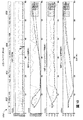
図8は、一部の実施形態による、滲出液が創傷から吸い出された時の気体漏れの検出800を示す。4つのプロット800a、800b、800cおよび800dは、表2における統計の未加工(または処理されていない)の値、表2における統計の非因果的Cusum、スライディング因果的Cusum、および累積因果的Cusumにそれぞれ対応して示される。プロット800a〜dにおいて、曲線802は、未加工の真空の平均の未加工のCusum値を表し、曲線804は、モータ電流の回転平均の標準偏差の未加工のCusum値を表わし、曲線806は、ポンプ速度の回転標準偏差の尖度の未加工のCusum値を表し、曲線808は、モータ電流の回転標準偏差の標準偏差を表わす。プロット800a〜dにおけるX軸は、継続時間(例えば、60秒)に対応する。プロット800aにおけるY軸は、対数的な尺度(統計の正規化した異なる未加工の値に対する)を表し、プロット800b〜dにおけるY軸は、Cusum値が一定の範囲(−1.0、1.0)にあるように線形に尺度化(または正規化)される。プロット800a〜dは、気体漏洩レート(例えば、約5秒で60sccm〜180sccm)における変化(例えば、増加)に対応するデータを取り込む。
FIG. 8 illustrates
図9は、一部の実施形態による、滲出液が創傷から吸い出された時の流体レートの変化の検出900を示す。4つのプロット900a〜dは、表2における統計(802、804、806および808と明示される)の未加工の(または処理されていない)値、統計の非因果的Cusum、スライディング因果的Cusum、および累積因果的Cusumにそれぞれ対応して示される。プロット800a〜dは、滲出液のボーラスが流体流路内に放出された(例えば、約5秒において)ことによる、滲出液流量の変化(例えば、増加)に対応するデータを取り込む。
FIG. 9 illustrates
図10は、一部の実施形態による、滲出液が創傷から吸い出された時の真空レベルの変化の検出1000を示す。4つのプロット1000a〜dは、表2における統計(802、804、806および808と明示される)の未加工の(または処理されていない)値、統計の非因果的Cusum、スライディング因果的Cusum、および累積因果的Cusumにそれぞれ対応して示される。プロット1000a〜dは、ポンプによって与えられる真空レベル(例えば、約18秒で−80mmHg〜−120mmHg)における変化(例えば、増加)に対応するデータを取り込む。
FIG. 10 illustrates
一定の実装において、国際特許公開PCT/US2017/017538で記載されるものと同様のプロットが、水または血液などの別のタイプの流体が流体流路内に加えられた時に得られ得る。 In certain implementations, a plot similar to that described in International Patent Publication PCT / US2017 / 017538 may be obtained when another type of fluid such as water or blood is added into the fluid flow path.
本明細書に記載の1つ以上の動作状態の検出は、さらに、患者の創傷での使用の検出のために使用され得る。例えば、図8を参照すると、モータ電流の回転平均の標準偏差(804)に関する種々のCusum(非因果的、スライディング因果的および累積因果的)は、約5秒で気体漏れの増加に応答する。800bに示される非因果的Cusumは、約5〜8秒において急激に増加し、約9〜30秒において平坦であり、ついで、約30秒後に徐々に減少する。800cに示されるスライディング因果的Cusumは、約5〜7秒において比較的平坦なままであり、約9秒において急激に減少し、その後は、比較的平坦である。800cに示される累積因果的Cusumは、約5〜8秒において比較的平坦なままであり、その後は、線形または単調に減少する。鮮鋭な、漸進的な、または線形の変化(増加または減少)を含むいくつかのこうしたパターンは、1つ以上の閾値と比較されて、気体漏洩レートの変化を検出することができる。気体漏洩レートのこうした変化の検出は、患者の創傷への使用を示すことができる。 The detection of one or more operating conditions described herein may further be used for detection of use in a patient's wound. For example, referring to FIG. 8, various Cusums (non-causal, sliding causal and cumulative causal) with respect to the standard deviation (804) of the rotational average of the motor current respond to the increase in gas leakage in about 5 seconds. The non-causal Cusum, shown at 800b, increases sharply in about 5-8 seconds, is flat in about 9-30 seconds, and then gradually decreases after about 30 seconds. The sliding causal Cusum, shown at 800c, remains relatively flat at about 5-7 seconds, decreases sharply at about 9 seconds, and is relatively flat thereafter. The cumulative causal Cusum, shown at 800c, remains relatively flat at about 5-8 seconds and then decreases linearly or monotonically. Several such patterns, including sharp, progressive or linear changes (increase or decrease) can be compared to one or more thresholds to detect changes in gas leak rates. Detection of such changes in gas leak rate can indicate use on a patient's wound.
別の実施例として、図9を参照すると、ポンプ速度の回転標準偏差の尖度(806)に関する種々のCusum(非因果的、スライディング因果的および累積因果的)は、約5秒で滲出液流量の増加に応答する。プロット900b〜dに示されるように、曲線806は、約6秒後に実質的に周期的であり、約20、25および35秒でいくつかの明確に区別できるピークに到達する。滲出液流量の変化を示すこうしたパターンは、例えば、1つ以上の閾値と比較することによって検出されてもよく、患者の創傷への使用の表示を提供するために使用され得る。
As another example, referring to FIG. 9, various Cusums (non-causal, sliding-causal and cumulative-causal) with respect to the kurtosis (806) of the rotational standard deviation of the pump speed have an effusion rate in about 5 seconds Respond to the increase in As shown in plots 900b-d,
さらに別の実施例として、図10を参照すると、平均真空(802)に関する種々のCusum(非因果的、スライディング因果的および累積因果的)は、約18秒で真空レベルの増加に応答する。1000bに示される非因果的Cusumは、約18秒後に線形または単調に増加する。1000cに示される累積因果的Cusumは、約18秒後、線形または単調に増加したままである。線形の変化(増加または減少)を含むいくつかのこうしたパターンは、1つ以上の閾値と比較されて、真空レベルの変化を検出することができる。気体漏洩レートのこうした変化の検出は、患者の創傷への使用を示すことができる。 As yet another example, referring to FIG. 10, various Cusums (non-causal, sliding causal and cumulative causal) for the average vacuum (802) respond to the increase in vacuum level in about 18 seconds. The non-causal Cusum, shown at 1000b, increases linearly or monotonically after about 18 seconds. The cumulative causal Cusum shown at 1000 c remains linearly or monotonically increasing after about 18 seconds. Several such patterns, including linear changes (increase or decrease) can be compared to one or more thresholds to detect changes in vacuum level. Detection of such changes in gas leak rate can indicate use on a patient's wound.
血液の存在または血液の流量の変化は、例えば、国際特許公開PCT/US2017/017538に記載のようなモータ電流の回転標準偏差(808)の標準偏差に基づいて検出され得る。気体漏洩レート、真空レベル、滲出液流量または血液流量の変化のうち任意の1つ以上の検出は、患者の創傷への使用の表示を提供するために使用され得る。 The presence of blood or changes in blood flow can be detected based on the standard deviation of the rotational standard deviation (808) of the motor current as described, for example, in International Patent Publication No. PCT / US2017 / 017538. Detection of any one or more of changes in gas leak rate, vacuum level, exudate flow rate or blood flow rate may be used to provide an indication of use on a patient's wound.
他の変化形
一部の実施形態では、陰圧創傷療法デバイスの準拠した使用および準拠しない使用を検出するための装置が開示される。装置は、メモリデバイスおよびプロセッサを含むことができる。メモリデバイスは、陰圧源と創傷被覆材を接続する流体流路内のある期間にわたる圧力の大きさを示す、圧力データを記憶することができる。プロセッサは、メモリデバイスと通信することができる。プロセッサは、陰圧源が創傷被覆材に陰圧を与えた時に、創傷被覆材が創傷に結合されているかどうかをある期間にわたる大きさの変化から決定することができ、陰圧源が創傷被覆材に陰圧を与えた時に創傷被覆材が創傷に結合されていることの決定に応答して、第1の表示を出力することができ、陰圧源が創傷被覆材に陰圧を与えた時に創傷被覆材が創傷に結合されていないことの決定に応答して、第1の表示とは異なる第2の表示を出力することができる。
Other Variations In some embodiments, an apparatus for detecting compliant and non-compliant use of a negative pressure wound therapy device is disclosed. An apparatus can include a memory device and a processor. The memory device can store pressure data indicating the magnitude of pressure over time in the fluid flow path connecting the negative pressure source and the wound dressing. The processor can communicate with the memory device. The processor can determine from the change in size over time whether the wound dressing is attached to the wound when the negative pressure source applies negative pressure to the wound dressing, the negative pressure source being the wound dressing. In response to determining that the wound dressing is attached to the wound when applying negative pressure to the material, a first indication may be output, the negative pressure source applying negative pressure to the wound dressing Sometimes in response to the determination that the wound dressing is not coupled to the wound, a second indication different from the first indication can be output.
上記の段落に記載の装置は、以下の特徴のうちの1つ以上を含み得る:装置は、通信ネットワークを介して圧力データを受信するように構成される、受信機をさらに含むことができる。通信ネットワークは、無線通信ネットワークであることができる。プロセッサは、ある期間にわたる大きさの変化の不規則性の測定を閾値と比較して、創傷被覆材が創傷に結合されているかどうかを決定することができる。プロセッサは、ある期間にわたる大きさに基づいて統計動作、トレンディング動作、フィルタリング動作、累積合計動作、またはローパスフィルタリング動作を実行して、出力値を生成することと、出力値が定常状態よりも混沌とした状態を示す決定に応じて、創傷被覆材が創傷に結合されていると決定することと、を行うことができる。プロセッサは、ある期間にわたる大きさを圧力パターンと比較して、創傷被覆材が創傷に結合されているかどうかを決定することができる。プロセッサは、グラフイックユーザーインタフェースへのユーザーに対する呈示のために第2の表示を出力するために、第2の表示を出力することができる。プロセッサは、グラフイックユーザーインタフェースへのユーザーに対する呈示のために警告を生成して伝えるために、第2の表示を出力することができる。プロセッサは、デバイス使用データが陰圧源の準拠した使用と関連することを示すために、メモリデバイスに、第1の表示と関連するデバイス使用データを記憶することができる。プロセッサは、デバイス使用データが陰圧源の準拠しない使用と関連することを示すために、メモリデバイスに、第2の表示と関連するデバイス使用データを記憶することができる。 The apparatus according to the above paragraph may include one or more of the following features: The apparatus may further include a receiver configured to receive pressure data via the communication network. The communication network can be a wireless communication network. The processor can compare the measurement of the change in magnitude over time to a threshold to determine if the wound dressing is attached to the wound. The processor performs a statistical operation, a trending operation, a filtering operation, a cumulative total operation, or a low pass filtering operation based on the magnitude over a period of time to generate an output value, and the output value is more chaotic than the steady state. And determining that the wound dressing is attached to the wound. The processor can compare the magnitude over time to the pressure pattern to determine if the wound dressing is attached to the wound. The processor can output a second display to output a second display for presentation to the user on the graphical user interface. The processor can output a second display to generate and communicate an alert for presentation to the user on the graphical user interface. The processor may store device usage data associated with the first display in the memory device to indicate that the device usage data is associated with compliant usage of the negative pressure source. The processor may store device usage data associated with the second display in the memory device to indicate that the device usage data is associated with non-compliant usage of the negative pressure source.
前述の2つの段落のいずれかに記載した装置の動作方法または製造方法が開示される。 A method of operation or manufacturing of the device described in any of the two preceding paragraphs is disclosed.
本明細書で提供される閾値、限界値、期間などの値は、絶対的なものであることを意図するものではなく、したがっておおよそのものであり得る。さらに、本明細書で提供される任意の閾値、限界値、期間などは、自動的にまたはユーザーによって、固定されるかまたは変えられ得る。さらに、本明細書で使用される場合、参照値に関連した、超える、超、未満などの相対的な程度を表す用語は、参照値と等しい場合も包含することが意図される。例えば、正の方向に参照値を超えることは、参照値以上であることを包含することができる。その上、本明細書で使用される場合、参照値に関連した、超える、超、未満などの相対的な程度を表す用語は、参照値に関連した、未満である、未満、超などの開示された関係とは逆のものも包含することが意図される。また、種々のプロセスのブロックは、ある値が特定の閾値に達するかまたは達しないかを判定することに関して説明され得るが、ブロックは、例えば、ある値が(i)閾値未満であるかもしくは閾値を超えているか、または(ii)閾値を満たすかもしくは満たしていないかに関しても同様に解釈され得る。 The values of thresholds, limits, periods, etc. provided herein are not intended to be absolute and may therefore be approximate. Furthermore, any thresholds, limits, durations, etc. provided herein may be fixed or changed automatically or by the user. Further, as used herein, terms representing relative degrees, such as greater than, greater than, less than, etc., associated with a reference value are intended to encompass the case where the reference value is also equal. For example, exceeding the reference value in the positive direction can include being greater than or equal to the reference value. Moreover, as used herein, the terms representing relative degrees such as, above, above, below, etc. associated with a reference value are associated with, eg, less than, above, etc. It is intended to encompass the reverse of the relationship that has been made. Also, although blocks of various processes may be described in terms of determining whether a value reaches or does not reach a particular threshold, the block may, for example, have a value below (i) the threshold or a threshold Similarly, it can be similarly interpreted as to whether or not (ii) the threshold is met or not met.
特定の態様、実施形態、または実施例に関連して説明される特性、物質、特徴、または群は、本明細書に記載される他の任意の態様、実施形態、または実施例に、これらと両立できないことがない限り、適用可能であることを理解されたい。(あらゆる特許請求の範囲、要約書、および図面を含む)本明細書において開示されるすべての特徴、および/またはそのように開示されるあらゆる方法もしくはプロセスのすべてのステップは、そのような特徴および/またはステップのうち少なくともいくつかが相互に排他的である組み合わせを除いて、任意の組み合わせで組み合わされてよい。本発明の保護するものは、前述の任意の実施形態の詳細に限定されない。保護するものは、本明細書(添付の任意の特許請求の範囲、要約書、及び図面を含む)において開示される特徴のうちの任意の新規なもの、もしくは任意の新規な組み合わせに及び、または同様に開示される任意の方法またはプロセスのステップのうちの任意の新規なもの、もしくは任意の新規な組み合わせに及ぶ。 The features, materials, features or groups described in connection with particular aspects, embodiments, or examples refer to any other aspect, embodiment, or example described herein. It should be understood that as long as there is no conflict, it is applicable. All features disclosed herein (including any claims, abstracts, and drawings) and / or all steps of any method or process so disclosed are such features and And / or may be combined in any combination except combinations where at least some of the steps are mutually exclusive. The protection of the present invention is not limited to the details of any of the foregoing embodiments. What is protected extends to any novel one or any novel combination of the features disclosed in the specification (including any claims, abstracts and drawings attached hereto), or It extends to any novel or any novel combination of steps of any method or process similarly disclosed.
一定の実施形態が説明されてきたが、これらの実施形態は、単に例として提示されており、保護範囲を限定することを意図するものではない。実際、本明細書に記載の新規な方法及びシステムは、様々な他の形態で具現化されてもよい。さらに、本明細書に記載の方法及びシステムの形態において、様々な省略、置換、及び変形がなされ得る。一部の実施形態では、図示および/または開示されたプロセスにおいて実施される実際のステップは、図に示されたステップとは異なり得ることを、当業者は認識するであろう。実施形態によっては、上述したステップのうちの特定のステップが除去される場合があり、別のものが加えられる場合もある。例えば、開示されるプロセスで実施される実際のステップおよび/またはステップの順序は、図で示したものとは異なっていてもよい。実施形態によっては、上述したステップのうちの特定のステップが除去される場合があり、別のものが加えられる場合もある。例えば、図に示した様々な構成要素が、プロセッサ、コントローラ、ASIC、FPGA、および/または専用ハードウエア上のソフトウエアおよび/またはファームウエアとして実装されてもよい。プロセッサ、ASIC、FPGAなどのハードウエア構成要素には論理回路が含まれ得る。さらに、上記に開示された特定の実施形態の特徴及び特性は、様々な方法で組み合わせることができ、さらなる実施形態を形成することができるが、その全てが本開示の範囲内に収まることになる。 While certain embodiments have been described, these embodiments are presented by way of example only and are not intended to limit the scope of protection. In fact, the novel methods and systems described herein may be embodied in various other forms. Moreover, various omissions, substitutions and changes in the form of the methods and systems described herein may be made. One of ordinary skill in the art will recognize that in some embodiments, the actual steps performed in the illustrated and / or disclosed processes may differ from the steps illustrated in the figures. In some embodiments, certain of the steps described above may be removed and others may be added. For example, the actual steps and / or order of steps performed in the processes disclosed may be different from those shown in the figures. In some embodiments, certain of the steps described above may be removed and others may be added. For example, the various components shown in the figures may be implemented as software and / or firmware on a processor, controller, ASIC, FPGA, and / or dedicated hardware. Hardware components such as processors, ASICs, FPGAs, etc. may include logic circuits. Moreover, the features and characteristics of the specific embodiments disclosed above can be combined in various ways to form further embodiments, all of which will fall within the scope of the present disclosure. .
本明細書で図示され、説明されるユーザーインターフェーススクリーンには、追加の構成要素および/または代替の構成要素が含まれ得る。これらの構成要素には、メニュー、リスト、ボタン、テキストボックス、ラベル、ラジオボタン、スクロールバー、スライダー、チェックボックス、コンボボックス、ステータスバー、ダイアログボックス、ウィンドウなどが含まれ得る。ユーザーインターフェーススクリーンには、追加の情報、および/または代替の情報が含まれ得る。構成要素は、任意の好適な順番に配置され、グループ化され、標示され得る。 The user interface screens illustrated and described herein may include additional components and / or alternative components. These components may include menus, lists, buttons, text boxes, labels, radio buttons, scroll bars, sliders, check boxes, combo boxes, status bars, dialog boxes, windows, and the like. The user interface screen may include additional information, and / or alternative information. The components may be arranged, grouped and labeled in any suitable order.
本開示には、一定の実施形態、実施例、および適用例が含まれるが、本開示は、具体的に開示された実施形態の範囲を超えて、他の代替の実施形態および/または使用ならびにその明らかな変更形およびその等価物にまで及び、これには本明細書に記載された特徴および利点の全てを提供しているとは限らない実施形態が含まれることは、当業者に理解されるはずである。したがって、本開示の範囲は、本明細書における好ましい実施形態の特定の開示によって限定されることを意図するものではなく、本明細書に提示されるまたはこの後に提示される特許請求の範囲によって画定され得る。 While the present disclosure includes certain embodiments, examples, and applications, the present disclosure extends beyond the scope of the specifically disclosed embodiments and to other alternative embodiments and / or uses and It will be understood by those skilled in the art that the present invention includes embodiments that extend to the obvious modifications and equivalents thereof, which do not necessarily provide all of the features and advantages described herein. It should be Accordingly, the scope of the present disclosure is not intended to be limited by the specific disclosure of preferred embodiments herein, but is defined by the claims presented herein or later presented. It can be done.
「し得る(can)」、「できる(could)」、「可能性がある(might)」、または「場合がある(may)」などの条件付き言い回しは、別途具体的に記載されない限り、または使用される文脈の範囲内で別途解釈されない限り、一定の実施形態が、特定の特徴、要素、またはステップを含む一方で、他の実施形態は含まないということの伝達を意図するのが通例である。したがって、こうした条件付き言い回しは、特徴、要素、またはステップが1つ以上の実施形態に多少なりとも必要とされるという示唆、またはこれらの特徴、要素、および/もしくはステップが特定の任意の実施形態に含まれているかどうか、もしくは該実施形態で実施されるべきかどうかを、ユーザー入力または命令の有無にかかわらず決定するためのロジックが、1つ以上の実施形態に必然的に含まれているという示唆を必ずしも意図するものではない。「備える(comprising)」、「含む(including)」、及び「有する(having)」などの用語は、同義語であり、包含的に非限定様式で用いられ、追加の要素、特徴、行為、及び動作などを排除するものではない。また、用語「または(or)」は、包括的な意味で(排他的な意味ではなく)用いられることで、例えば要素の列記をつなぐのに使用される場合、列記の要素のうちの1つ、一部、または全てを意味することになる。さらに、用語「各々」は、本明細書で使用される場合、通常の意味を有するのに加えて、用語「各々」が適用されている一連の要素の任意のサブセットも意味し得る。 Conditional phrases such as "can", "could", "might", or "may", unless stated otherwise, or Unless otherwise interpreted within the context of the context in which it is used, it is customary to convey that certain embodiments include certain features, elements or steps, but not other embodiments. is there. Thus, such conditional language implies that a feature, element, or step is required more or less in one or more embodiments, or any embodiment in which these features, elements, and / or steps are specific. Logic is necessarily included in one or more of the embodiments for determining whether or not to be implemented in the embodiments with or without user input or instructions. The suggestion is not necessarily intended. Terms such as "comprising", "including", and "having" are synonymous and are used in an inclusive and non-limiting manner, with additional elements, features, acts, and It does not exclude motion and the like. Also, the term "or" is used in an inclusive sense (not in an exclusive sense), eg, when used to link a list of elements, one of the listed elements Will mean some or all. Furthermore, the term "each" as used herein may mean, in addition to having its ordinary meaning, any subset of the series of elements to which the term "each" is applied.
語句「X、Y、およびZのうちの少なくとも1つ」などの連言的言い回しは、別途具体的に記載されない限り、ある項目や用語などが、Xか、Yか、Zのいずれかであり得ることを示唆するのに一般的に用いられる文脈によって、別途解釈されるものである。したがって、こうした連言的言い回しは、一定の実施形態が、少なくとも1つのXと、少なくとも1つYと、少なくとも1つのZとを含むことを必要とするという示唆を必ずしも意図するものではない。 A conjunctive phrase such as the phrase "at least one of X, Y, and Z" is an item or term, such as X, Y, or Z, unless specifically stated otherwise. Depending on the context generally used to suggest that it is obtained, it is to be interpreted separately. Thus, such conjunctive language is not necessarily meant to imply that certain embodiments require including at least one X, at least one Y, and at least one Z.
本明細書で使用される「およそ」、「約」、「概して」、および「実質的に」という用語などの、本明細書で使用される程度を表す言い回しは、所望の機能を依然として果たすかまたは所望の結果をもたらす所定の値、量、または特性に近い値、量、または特性を表すものである。例えば、「およそ」、「約」、「概して」、及び「実質的に」という用語は、所定の量の10%未満以内、5%未満以内、1%未満以内、0.1%未満以内、及び0.01%未満以内の量を意味し得る。別の例として、一定の実施形態において、「概して平行」及び「実質的に平行」という用語は、丁度平行である状態から15度以下、10度以下、5度以下、3度以下、1度以下、または0.1度以下ずれている値、量、または特性を意味する。 Does the term "degree" used herein such as the terms "about", "about", "generally", and "substantially" as used herein still perform the desired function? Or, it represents a value, amount, or characteristic close to a predetermined value, amount, or characteristic that produces a desired result. For example, the terms "about", "about", "generally", and "substantially" are less than 10%, less than 5%, less than 1%, less than 0.1% of a given amount. And amounts of less than 0.01% may be meant. As another example, in certain embodiments, the terms "generally parallel" and "substantially parallel" are less than 15 degrees, less than 10 degrees, less than 5 degrees, less than 3 degrees, 1 degree from just parallel Less than or equal to or less than 0.1 degrees means a value, amount, or characteristic.
本開示の範囲は、本節におけるまたは本明細書の他の箇所における好ましい実施形態の特定の開示によって制限されることを意図するものではなく、本節においてまたは本明細書の他の箇所において提示されているか、またはこの後に提示される特許請求の範囲によって画定され得る。本特許請求の範囲の言い回しは、本特許請求の範囲で用いられている言い回しに基づいて広い意味で解釈されるべきであり、本明細書で説明されている例または本出願の手続きの間に説明される例に限定されるものではなく、それらの例は非排他的なものとして解釈されるべきである。 The scope of the present disclosure is not intended to be limited by the particular disclosure of the preferred embodiments in this section or elsewhere in the present specification, and is presented in this section or elsewhere in the present specification. Or may be defined by the claims presented thereafter. The language of the claims should be interpreted broadly based on the language used in the claims, and between the examples described herein or the prosecution of the application. It is not intended to be limited to the examples described, which are to be construed as non-exclusive.
Claims (53)
創傷被覆材に流体流路を介して結合して、前記創傷被覆材に陰圧を与えるように構成される、陰圧源と、
前記流体流路内の圧力を監視するように構成される、センサと、
コントローラであって、
前記陰圧源が目標圧力範囲内に前記流体流路内の陰圧を維持する間、前記創傷被覆材が、混沌とした状態を示す継続時間にわたる前記流体流路内の圧力の大きさの変化から、前記創傷被覆材が創傷に結合されていることを決定すること、
前記創傷被覆材が前記創傷に結合されていることを示す、第1の表示を出力すること、
前記陰圧源が前記目標圧力範囲内に前記流体流路内の陰圧を維持する間、前記創傷被覆材が、定常状態を示す前記継続時間にわたる前記流体流路内の圧力の前記大きさの前記変化から、前記創傷に結合されていないことを決定すること、および
前記創傷被覆材が前記創傷に結合されていないことを示す、前記第1の表示とは異なる第2の表示を出力すること、を行うように構成される、コントローラと、を備える、装置。 An apparatus for applying negative pressure to a wound,
A negative pressure source configured to couple to the wound dressing via a fluid flow path to apply negative pressure to the wound dressing;
A sensor configured to monitor pressure in the fluid flow path;
A controller,
While the negative pressure source maintains the negative pressure in the fluid flow path within the target pressure range, the change in the magnitude of the pressure in the fluid flow path over a sustained period of time in which the wound dressing exhibits a chaotic condition Determining that the wound dressing is attached to a wound from
Outputting a first indication indicating that the wound dressing is coupled to the wound;
The magnitude of pressure in the fluid flow path over the duration of the steady state is indicated by the wound dressing while the negative pressure source maintains the negative pressure in the fluid flow path within the target pressure range. Determining from the change that it is not coupled to the wound, and outputting a second indication different from the first indication, which indicates that the wound dressing is not coupled to the wound A controller configured to:.
前記継続時間にわたる前記大きさに基づく統計動作、トレンディング動作、フィルタリング動作、累積合計動作、またはローパスフィルタリング動作を実行して、出力値を生成することと、
前記出力値が前記定常状態を示す決定に応じて、前記継続時間にわたる前記大きさの前記変化が、前記定常状態を示すことを決定することと、を行うようにさらに構成される、請求項1〜6のいずれか1項以上に記載の装置。 The controller
Performing an statistical operation based on the magnitude over the duration, a trending operation, a filtering operation, a cumulative sum operation, or a low pass filtering operation to generate an output value;
Generating, in response to the determination that the output value is indicative of the steady state, determining that the change in magnitude over the duration represents the steady state. A device according to any one or more of 6.
メモリデバイスに記憶するために前記第1の表示を出力するように、または
前記メモリデバイスに記憶するために前記第2の表示を出力するようにさらに構成される、請求項1〜12のいずれか1項以上に記載の装置。 The controller
13. Any one of claims 1 to 12, further configured to output the first indication for storage in a memory device or to output the second indication for storage in the memory device. Apparatus according to one or more of the above.
送信機に通信ネットワークを介して前記第1の表示をコンピュータ装置に送信させることによって、前記第1の表示を出力するように、または
前記送信機に前記通信ネットワークを介して前記第2の表示を前記コンピュータ装置に送信させることによって、前記第2の表示を出力するようにさらに構成される、請求項1〜13のいずれか1項以上に記載の装置。 The controller
By causing the transmitter to transmit the first display to the computer device via the communication network, the first display may be output, or the transmitter may transmit the second display via the communication network. 14. An apparatus according to any one or more of the preceding claims, further configured to output the second display by causing the computer apparatus to transmit.
ユーザーへの呈示のために前記第1の表示を出力するように、または
前記ユーザーへの呈示のために前記第2の表示を出力するようにさらに構成される、請求項1〜14のいずれか1項以上に記載の装置。 The controller
15. Any of the preceding claims, further configured to output the first indication for presentation to a user, or to output the second indication for presentation to the user. Apparatus according to one or more of the above.
陰圧源を使用して、流体流路を介して創傷被覆材に陰圧を与えることと、
前記流体流路内の圧力をセンサを用いて監視することと、
目標圧力範囲内に前記流体流路内の陰圧を維持する間、定常状態を示す継続時間にわたる前記流体流路内の圧力の大きさの変化から、前記創傷被覆材が創傷に結合されていないことを決定することと、
前記継続時間にわたる前記大きさの前記変化から、前記創傷被覆材が前記創傷に結合されていることの決定に応じて、前記創傷被覆材が前記創傷に結合されていることを示す第1の表示を出力することと、
前記継続時間にわたる前記大きさの前記変化から、前記創傷被覆材が前記創傷に結合されていないことの決定に応じて、前記創傷被覆材が前記創傷に結合されていないことを示す前記第1の表示とは異なる第2の表示を出力することと、を含む、方法。 A method of operation of a negative pressure wound therapy apparatus, said method comprising
Applying negative pressure to the wound dressing via the fluid flow path using a negative pressure source;
Monitoring the pressure in the fluid flow path using a sensor;
While maintaining negative pressure in the fluid flow path within the target pressure range, the wound dressing is not coupled to the wound from changes in the magnitude of pressure in the fluid flow path over a duration indicative of steady state To determine that
A first indication indicating that the wound dressing is attached to the wound in response to the determination that the wound dressing is attached to the wound from the change in the size over the duration of time Output and
The first indicating that the wound dressing is not coupled to the wound in response to the determination that the wound dressing is not coupled to the wound from the change in the size over the duration of time. Outputting a second indication different from the indication.
前記決定することが、前記出力値が前記定常状態を示す決定に応じて、前記継続時間にわたる前記大きさの前記変化が前記定常状態を示すことを決定することを含む、請求項20〜25のいずれか1項以上に記載の方法。 Further comprising performing said magnitude based statistical operation, trending operation, filtering operation, cumulative total operation, or low pass filtering operation over a period of time to generate an output value,
26. The method according to claim 20, wherein said determining comprises determining that said change in said magnitude over said duration represents said steady state, in response to the determination that said output value indicates said steady state. The method according to any one or more.
創傷被覆材に流体流路を介して結合して、前記創傷被覆材に陰圧を与えるように構成される、陰圧源と、
前記流体流路内の圧力を監視するように構成される、センサと、
コントローラであって、
前記流体流路内の前記圧力に少なくとも部分的に基づいて、前記流体流路内の気体の流れの変化の検出、前記流体流路内の滲出液の流れの変化、前記流体流路内の真空レベルの変化の検出、または前記流体流路内の血液の存在の検出のうちの少なくとも1つに基づいて、前記創傷被覆材が、創傷に結合されていることを決定すること、および
前記創傷被覆材が前記創傷に結合されていることの表示を出力すること、を行うように構成されるコントローラと、を備える、装置。 An apparatus for applying negative pressure to a wound,
A negative pressure source configured to couple to the wound dressing via a fluid flow path to apply negative pressure to the wound dressing;
A sensor configured to monitor pressure in the fluid flow path;
A controller,
At least partially based on the pressure in the fluid flow channel, detecting a change in flow of gas in the fluid flow channel, a change in flow of exudate in the fluid flow channel, a vacuum in the fluid flow channel Determining that the wound dressing is coupled to a wound based on at least one of detection of a change in level or detection of the presence of blood in the fluid flow channel, and the wound covering A controller configured to output an indication that material is coupled to the wound.
陰圧源を用いて、流体流路を介して創傷被覆材に陰圧を与えることと、
前記流体流路内の圧力を監視することと、
前記流体流路内の前記圧力に少なくとも部分的に基づいて、前記流体流路内の気体の流れの変化の検出、前記流体流路内の滲出液の流れの変化、前記流体流路内の真空レベルの変化の検出、または前記流体流路内の血液の存在の検出のうちの1つから、前記創傷被覆材が創傷に結合されていることを決定することと、
前記創傷被覆材が前記創傷に結合されていることの表示を出力することと、を含む、方法。 A method of applying negative pressure to a wound,
Applying negative pressure to the wound dressing via the fluid flow path using a negative pressure source;
Monitoring the pressure in the fluid flow path;
At least partially based on the pressure in the fluid flow channel, detecting a change in flow of gas in the fluid flow channel, a change in flow of exudate in the fluid flow channel, a vacuum in the fluid flow channel Determining that the wound dressing is bound to a wound from one of detecting a change in level or detecting the presence of blood in the fluid flow path;
Outputting an indication that the wound dressing is attached to the wound.
Priority Applications (1)
| Application Number | Priority Date | Filing Date | Title |
|---|---|---|---|
| JP2022068784A JP7401587B2 (en) | 2016-05-13 | 2022-04-19 | Automated wound bond detection in negative pressure wound therapy systems |
Applications Claiming Priority (5)
| Application Number | Priority Date | Filing Date | Title |
|---|---|---|---|
| US201662335978P | 2016-05-13 | 2016-05-13 | |
| US62/335,978 | 2016-05-13 | ||
| US201662378856P | 2016-08-24 | 2016-08-24 | |
| US62/378,856 | 2016-08-24 | ||
| PCT/US2017/032545 WO2017197357A1 (en) | 2016-05-13 | 2017-05-12 | Automatic wound coupling detection in negative pressure wound therapy systems |
Related Child Applications (1)
| Application Number | Title | Priority Date | Filing Date |
|---|---|---|---|
| JP2022068784A Division JP7401587B2 (en) | 2016-05-13 | 2022-04-19 | Automated wound bond detection in negative pressure wound therapy systems |
Publications (2)
| Publication Number | Publication Date |
|---|---|
| JP2019514591A true JP2019514591A (en) | 2019-06-06 |
| JP2019514591A5 JP2019514591A5 (en) | 2020-06-25 |
Family
ID=58772967
Family Applications (2)
| Application Number | Title | Priority Date | Filing Date |
|---|---|---|---|
| JP2018558161A Pending JP2019514591A (en) | 2016-05-13 | 2017-05-12 | Automated wound binding detection in negative pressure wound therapy systems |
| JP2022068784A Active JP7401587B2 (en) | 2016-05-13 | 2022-04-19 | Automated wound bond detection in negative pressure wound therapy systems |
Family Applications After (1)
| Application Number | Title | Priority Date | Filing Date |
|---|---|---|---|
| JP2022068784A Active JP7401587B2 (en) | 2016-05-13 | 2022-04-19 | Automated wound bond detection in negative pressure wound therapy systems |
Country Status (7)
| Country | Link |
|---|---|
| US (2) | US11602461B2 (en) |
| EP (2) | EP4059530A1 (en) |
| JP (2) | JP2019514591A (en) |
| CN (1) | CN109069713A (en) |
| AU (1) | AU2017261814B2 (en) |
| CA (1) | CA3023932A1 (en) |
| WO (1) | WO2017197357A1 (en) |
Families Citing this family (17)
| Publication number | Priority date | Publication date | Assignee | Title |
|---|---|---|---|---|
| CN107580509B (en) | 2015-05-18 | 2021-06-15 | 史密夫及内修公开有限公司 | Negative pressure wound therapy apparatus and method |
| WO2017027850A1 (en) | 2015-08-13 | 2017-02-16 | Smith & Nephew, Inc. | Systems and methods for applying reduced pressure therapy |
| AU2017227923B2 (en) | 2016-03-04 | 2022-01-27 | Smith & Nephew Plc | Negative pressure wound therapy apparatus for post breast surgery wounds |
| EP4059530A1 (en) | 2016-05-13 | 2022-09-21 | Smith & Nephew, Inc. | Automatic wound coupling detection in negative pressure wound therapy systems |
| EP3500222B1 (en) * | 2016-08-19 | 2020-11-04 | T.J.Smith And Nephew, Limited | Reduced pressure therapy systems and methods for monitoring patient movement |
| CA3053299A1 (en) | 2017-02-15 | 2018-08-23 | Smith & Nephew Pte. Limited | Negative pressure wound therapy apparatuses and methods for using the same |
| AU2018228663B2 (en) | 2017-02-28 | 2023-05-18 | T.J.Smith And Nephew, Limited | Multiple dressing negative pressure wound therapy system |
| WO2019063467A1 (en) | 2017-09-29 | 2019-04-04 | T.J.Smith And Nephew,Limited | Negative pressure wound therapy apparatus with removable panels |
| GB201813282D0 (en) | 2018-08-15 | 2018-09-26 | Smith & Nephew | System for medical device activation and opertion |
| WO2019157466A1 (en) | 2018-02-12 | 2019-08-15 | Healyx Labs, Inc. | Negative pressure wound therapy systems, devices, and methods |
| GB201804347D0 (en) | 2018-03-19 | 2018-05-02 | Smith & Nephew Inc | Securing control of settings of negative pressure wound therapy apparatuses and methods for using the same |
| EP3787704A1 (en) | 2018-04-30 | 2021-03-10 | Smith & Nephew Asia Pacific Pte Limited | Systems and methods for controlling dual mode negative pressure wound therapy apparatus |
| USD888225S1 (en) | 2018-04-30 | 2020-06-23 | Smith & Nephew Asia Pacific Pte. Limited | Pump and canister assembly for negative pressure wound therapy |
| GB201808438D0 (en) | 2018-05-23 | 2018-07-11 | Smith & Nephew | Systems and methods for determining blockages in a negative pressure wound therapy system |
| GB201818552D0 (en) | 2018-11-14 | 2018-12-26 | Smith & Nephew | Health care provider autorization of data acquisition by sensor enabled wound dressing and devices |
| CN110251741A (en) * | 2019-05-30 | 2019-09-20 | 天津市同业科技发展有限公司 | It is a kind of to can be realized the Multifunctional central attraction system remotely monitored |
| CA3170646A1 (en) | 2020-01-29 | 2021-08-05 | Convatec Limited | A pump assembly and a wound therapy apparatus |
Citations (6)
| Publication number | Priority date | Publication date | Assignee | Title |
|---|---|---|---|---|
| US20060173253A1 (en) * | 1999-04-06 | 2006-08-03 | Kci Licensing, Inc. | Systems and methods for detection of wound fluid blood and application of phototherapy in conjunction with reduced pressure wound treatment system |
| US20110130712A1 (en) * | 2008-05-21 | 2011-06-02 | Moris Topaz | Wound healing device |
| JP2013523279A (en) * | 2010-03-31 | 2013-06-17 | ケーシーアイ ライセンシング インコーポレイテッド | System and method for identifying fluid leak location in a drape using sensing technology |
| JP2014509875A (en) * | 2010-12-08 | 2014-04-24 | コンバテック・テクノロジーズ・インコーポレイテッド | Integrated system for assessing wound exudate |
| WO2015023515A1 (en) * | 2013-08-13 | 2015-02-19 | Smith & Nephew, Inc. | Systems and methods for applying reduced pressure therapy |
| US20150133829A1 (en) * | 2013-11-14 | 2015-05-14 | Deroyal Industries, Inc. | System for Monitoring and Controlling Negative Pressure Wound Therapy |
Family Cites Families (915)
| Publication number | Priority date | Publication date | Assignee | Title |
|---|---|---|---|---|
| US6241704B1 (en) | 1901-11-22 | 2001-06-05 | Sims Deltec, Inc. | Drug pump systems and methods |
| US695270A (en) | 1901-12-05 | 1902-03-11 | George M Beringer | Vaccine-shield. |
| US3194239A (en) | 1963-01-16 | 1965-07-13 | Cornelius J P Sullivan | Suture provided with radiopaque free metal |
| US4832299A (en) | 1987-12-04 | 1989-05-23 | Pacesetter Infusion, Ltd. | Clamp fixture |
| GB2235877A (en) | 1989-09-18 | 1991-03-20 | Antonio Talluri | Closed wound suction apparatus |
| US5161525A (en) * | 1990-05-11 | 1992-11-10 | Puritan-Bennett Corporation | System and method for flow triggering of pressure supported ventilation |
| US6400996B1 (en) | 1999-02-01 | 2002-06-04 | Steven M. Hoffberg | Adaptive pattern recognition based control system and method |
| US6151019A (en) | 1992-04-15 | 2000-11-21 | Canon Kabushiki Kaisha | Method and apparatus for controlling access of stored data in a system having a plurality of information processing apparatuses connected to a network |
| US5219428A (en) | 1992-04-29 | 1993-06-15 | Becton, Dickinson And Company | Pole camp |
| US20010011224A1 (en) | 1995-06-07 | 2001-08-02 | Stephen James Brown | Modular microprocessor-based health monitoring system |
| US5960403A (en) | 1992-11-17 | 1999-09-28 | Health Hero Network | Health management process control system |
| US7624028B1 (en) | 1992-11-17 | 2009-11-24 | Health Hero Network, Inc. | Remote health monitoring and maintenance system |
| DE4301524A1 (en) | 1993-01-21 | 1994-07-28 | Jostra Medizintechnik | Medical unit or device for operating theaters, in particular heart-lung machine |
| US5533079A (en) | 1993-01-25 | 1996-07-02 | Medselect Systems, Inc. | Inventory monitoring apparatus |
| DE69422900T2 (en) * | 1993-12-01 | 2000-06-08 | Resmed Ltd | Continuous positive airway pressure (CPAP) device |
| US5473536A (en) | 1994-04-04 | 1995-12-05 | Spacelabs Medical, Inc. | Method and system for customizing the display of patient physiological parameters on a medical monitor |
| US5449347A (en) | 1994-07-05 | 1995-09-12 | The United States Of America As Represented By The Secretary Of The Air Force | Patient transport, plural power source suction apparatus |
| EP0777504B1 (en) | 1994-08-22 | 1998-10-21 | Kinetic Concepts, Inc. | Wound drainage equipment |
| US8280682B2 (en) | 2000-12-15 | 2012-10-02 | Tvipr, Llc | Device for monitoring movement of shipped goods |
| US5682525A (en) | 1995-01-11 | 1997-10-28 | Civix Corporation | System and methods for remotely accessing a selected group of items of interest from a database |
| WO1996027163A1 (en) | 1995-02-28 | 1996-09-06 | Clinicomp International, Inc. | Clinical critical care path system and method of using same |
| US5713856A (en) | 1995-03-13 | 1998-02-03 | Alaris Medical Systems, Inc. | Modular patient care system |
| DE19517699C2 (en) | 1995-05-13 | 1999-11-04 | Wilhelm Fleischmann | Device for vacuum sealing a wound |
| US6671563B1 (en) | 1995-05-15 | 2003-12-30 | Alaris Medical Systems, Inc. | System and method for collecting data and managing patient care |
| GB9523253D0 (en) | 1995-11-14 | 1996-01-17 | Mediscus Prod Ltd | Portable wound treatment apparatus |
| CA2253345C (en) | 1996-05-22 | 2004-10-26 | Universitaire Ziekenhuizen Leuven | Relational database compiled/stored on a memory structure |
| US6050940A (en) | 1996-06-17 | 2000-04-18 | Cybernet Systems Corporation | General-purpose medical instrumentation |
| EP1011420B1 (en) | 1996-09-19 | 2004-12-08 | Ortivus Aktiebolag | Portable telemedicine device |
| US5813972A (en) | 1996-09-30 | 1998-09-29 | Minnesota Mining And Manufacturing Company | Medical perfusion system with data communications network |
| US5989234A (en) | 1997-01-14 | 1999-11-23 | Deknatel Technology Corporation | Device and system for draining a body cavity and methods related thereto |
| US5960085A (en) | 1997-04-14 | 1999-09-28 | De La Huerga; Carlos | Security badge for automated access control and secure data gathering |
| US6055506A (en) | 1997-04-25 | 2000-04-25 | Unitron Medical Communications, Inc. | Outpatient care data system |
| AU9787498A (en) | 1997-10-02 | 1999-04-27 | Micromed Technology, Inc. | Implantable pump system |
| US5995937A (en) | 1997-11-07 | 1999-11-30 | Deroyal Industries, Inc. | Modular health-care information management system utilizing reusable software objects |
| CN1168507C (en) | 1997-12-27 | 2004-09-29 | 株式会社Jms | Blood circulation auxiliary device using continuous blood flow pump and diagnosis device for blood circulation state in organism |
| US7222054B2 (en) | 1998-03-03 | 2007-05-22 | Card Guard Scientific Survival Ltd. | Personal ambulatory wireless health monitor |
| US6801916B2 (en) | 1998-04-01 | 2004-10-05 | Cyberpulse, L.L.C. | Method and system for generation of medical reports from data in a hierarchically-organized database |
| US7647237B2 (en) | 1998-04-29 | 2010-01-12 | Minimed, Inc. | Communication station and software for interfacing with an infusion pump, analyte monitor, analyte meter, or the like |
| US6278999B1 (en) | 1998-06-12 | 2001-08-21 | Terry R. Knapp | Information management system for personal health digitizers |
| US6458109B1 (en) | 1998-08-07 | 2002-10-01 | Hill-Rom Services, Inc. | Wound treatment apparatus |
| GB9822341D0 (en) | 1998-10-13 | 1998-12-09 | Kci Medical Ltd | Negative pressure therapy using wall suction |
| US6353445B1 (en) | 1998-11-25 | 2002-03-05 | Ge Medical Systems Global Technology Company, Llc | Medical imaging system with integrated service interface |
| US6434572B2 (en) | 1998-11-25 | 2002-08-13 | Ge Medical Technology Services, Inc. | Medical diagnostic system management method and apparatus |
| US6540672B1 (en) | 1998-12-09 | 2003-04-01 | Novo Nordisk A/S | Medical system and a method of controlling the system for use by a patient for medical self treatment |
| AU4185600A (en) | 1999-04-01 | 2000-10-23 | Acist Medical Systems, Inc. | An integrated medical information management and medical device control system and method |
| EP1168997B1 (en) | 1999-04-02 | 2013-04-24 | KCI Licensing, Inc. | Vacuum assisted closure system with provision for introduction of agent |
| US6336900B1 (en) | 1999-04-12 | 2002-01-08 | Agilent Technologies, Inc. | Home hub for reporting patient health parameters |
| US20060064323A1 (en) | 1999-04-12 | 2006-03-23 | Alleckson Todd D | Data management center for patient monitoring |
| DE60028874T2 (en) | 1999-07-06 | 2006-11-09 | Canon K.K. | System for searching a device in the network |
| SE9902971L (en) | 1999-08-23 | 2001-02-24 | Two Inventors Hb | Method and apparatus for treating and adding an additive in the collection of a liquid |
| US6640246B1 (en) | 1999-09-17 | 2003-10-28 | Ge Medical Systems Global Technology Company, Llc | Integrated computerized materials management system |
| US6681003B2 (en) | 1999-10-05 | 2004-01-20 | Lifecor, Inc. | Data collection and system management for patient-worn medical devices |
| WO2001033457A1 (en) | 1999-10-29 | 2001-05-10 | Strategic Visualization, Inc. | Apparatus and method for providing medical services over a communication network |
| US7225809B1 (en) | 1999-11-01 | 2007-06-05 | Ric Investments, Llc | Method and apparatus for monitoring and controlling a medical device |
| US6406426B1 (en) | 1999-11-03 | 2002-06-18 | Criticare Systems | Medical monitoring and alert system for use with therapeutic devices |
| US6241739B1 (en) | 1999-11-12 | 2001-06-05 | Altair Instruments, Inc. | Microdermabrasion device and method of treating the skin surface |
| US6574518B1 (en) | 1999-11-29 | 2003-06-03 | General Electric Company | Method and apparatus for communicating operational data for a system unit in a medical diagnostic system |
| WO2001037922A2 (en) | 1999-11-29 | 2001-05-31 | Hill-Rom Services, Inc. | Wound treatment apparatus |
| US6602191B2 (en) | 1999-12-17 | 2003-08-05 | Q-Tec Systems Llp | Method and apparatus for health and disease management combining patient data monitoring with wireless internet connectivity |
| WO2001054753A2 (en) | 2000-01-21 | 2001-08-02 | Medical Research Group, Inc. | Microprocessor controlled ambulatory medical apparatus with hand held communication device |
| EP1248661B1 (en) | 2000-01-21 | 2012-08-22 | Medtronic MiniMed, Inc. | Ambulatory medical apparatus and method having telemetry modifiable control software |
| US7212829B1 (en) | 2000-02-28 | 2007-05-01 | Chung Lau | Method and system for providing shipment tracking and notifications |
| US6871211B2 (en) | 2000-03-28 | 2005-03-22 | Ge Medical Systems Information Technologies, Inc. | Intranet-based medical data distribution system |
| FR2807542B1 (en) | 2000-04-06 | 2006-09-29 | Capsule Technologie | METHOD AND SYSTEM FOR COLLECTING AND DISSEMINATING DATA FROM DEVICES, IN PARTICULAR MEDICAL DEVICES |
| US6460041B2 (en) | 2000-04-26 | 2002-10-01 | Inshift Technologies, Inc. | Browser-based database-access engine apparatus and method |
| AU2001261084A1 (en) | 2000-04-27 | 2001-11-07 | Brio Technology, Inc. | Method and apparatus for processing jobs on an enterprise-wide computer system |
| US6730024B2 (en) | 2000-05-17 | 2004-05-04 | Brava, Llc | Method and apparatus for collecting patient compliance data including processing and display thereof over a computer network |
| US7860583B2 (en) | 2004-08-25 | 2010-12-28 | Carefusion 303, Inc. | System and method for dynamically adjusting patient therapy |
| US10062457B2 (en) | 2012-07-26 | 2018-08-28 | Carefusion 303, Inc. | Predictive notifications for adverse patient events |
| US7035864B1 (en) | 2000-05-18 | 2006-04-25 | Endeca Technologies, Inc. | Hierarchical data-driven navigation system and method for information retrieval |
| EP1404213B1 (en) | 2000-05-19 | 2011-03-23 | Welch Allyn Protocol Inc | Patient monitoring system |
| DE60119100T2 (en) | 2000-06-23 | 2006-08-31 | Bodymedia, Inc. | SYSTEM FOR THE MONITORING OF HEALTH, WELL-BEING AND CONDITION |
| JP2004501735A (en) | 2000-06-30 | 2004-01-22 | ディジタル・エンジェル・コーポレーション | Remote monitoring system and method |
| US6847892B2 (en) | 2001-10-29 | 2005-01-25 | Digital Angel Corporation | System for localizing and sensing objects and providing alerts |
| US6559620B2 (en) | 2001-03-21 | 2003-05-06 | Digital Angel Corporation | System and method for remote monitoring utilizing a rechargeable battery |
| US7384267B1 (en) | 2000-07-20 | 2008-06-10 | Ge Medical Technology Services, Inc. | Automatic identification of medical staff training needs |
| EP1410198A2 (en) | 2000-08-22 | 2004-04-21 | Symbian Limited | A method of enabling a wireless information device to access data services |
| DE10047547B4 (en) | 2000-09-22 | 2007-03-29 | Siemens Ag | A method for troubleshooting a medical device and a medical device suitable for performing such a method |
| DE10047552B4 (en) | 2000-09-22 | 2007-01-04 | Siemens Ag | Medical device |
| US20030105649A1 (en) | 2000-09-27 | 2003-06-05 | Seth Sheiner | Automated data reporting system and method |
| AU2002220172A1 (en) | 2000-11-15 | 2002-05-27 | David M. Holbrook | Apparatus and method for organizing and/or presenting data |
| US6976977B2 (en) | 2000-12-06 | 2005-12-20 | Sherwood Services Ag | Vacuum setting and indication system for a drainage device |
| EP1216651A1 (en) | 2000-12-21 | 2002-06-26 | BrainLAB AG | Wireless medical acquisition and treatment system |
| US20020087360A1 (en) | 2001-01-02 | 2002-07-04 | Pettit Stephen W. | Immunization tracking method |
| US6723046B2 (en) | 2001-01-29 | 2004-04-20 | Cybernet Systems Corporation | At-home health data management method and apparatus |
| DE10106305A1 (en) | 2001-02-12 | 2002-08-29 | Siemens Ag | Method and medical system for improved utilization of a medical device and medical device |
| US7133869B2 (en) | 2001-03-06 | 2006-11-07 | Knowledge Vector, Inc. | Methods and systems for and defining and distributing information alerts |
| US7890887B1 (en) | 2001-03-07 | 2011-02-15 | Fonar Corporation | System and method for the operation of diagnostic medical equipment |
| GB0108215D0 (en) | 2001-04-02 | 2001-05-23 | Glaxo Group Ltd | Medicament dispenser |
| US7108683B2 (en) | 2001-04-30 | 2006-09-19 | Kci Licensing, Inc | Wound therapy and tissue management system and method with fluid differentiation |
| EP1256897A3 (en) | 2001-05-10 | 2009-12-09 | Siemens Aktiengesellschaft | Method for monitoring the course of a therapy for a patient in therapy |
| US20020177757A1 (en) | 2001-05-22 | 2002-11-28 | Siemens Medical Systems, Inc. | Systems and methods to facilitate an exchange of information associated with medical care provided to a patient |
| EP1260926A3 (en) | 2001-05-23 | 2009-12-09 | Siemens Aktiengesellschaft | System for capturing and informing of regionally grouped , daily-updated medical data |
| US7103578B2 (en) | 2001-05-25 | 2006-09-05 | Roche Diagnostics Operations, Inc. | Remote medical device access |
| US20020184055A1 (en) | 2001-05-29 | 2002-12-05 | Morteza Naghavi | System and method for healthcare specific operating system |
| US6902550B2 (en) | 2001-06-05 | 2005-06-07 | Atrium Medical Corporation | System for draining fluids |
| US7318015B2 (en) | 2001-06-13 | 2008-01-08 | Verizon Business Global Llc | Method, system and program product for generating scenarios utilizing graphical objects representing hierarchically arranged elements of a modeled environment |
| US6868528B2 (en) | 2001-06-15 | 2005-03-15 | Microsoft Corporation | Systems and methods for creating and displaying a user interface for displaying hierarchical data |
| KR20040015344A (en) | 2001-07-09 | 2004-02-18 | 노보 노르디스크 에이/에스 | Method and system for controlling data information between two portable medical apparatuses |
| PT1406567E (en) | 2001-07-12 | 2010-07-21 | Kci Medical Resources | Control of vacuum rate of change |
| US7643834B2 (en) | 2001-07-16 | 2010-01-05 | Wavemarket, Inc. | System for providing alert-based services to mobile stations in a wireless communications network |
| US6955664B2 (en) | 2001-07-17 | 2005-10-18 | D'antonio Consultants International, Inc. | Suction regulator and fluid drainage system |
| US6747556B2 (en) | 2001-07-31 | 2004-06-08 | Medtronic Physio-Control Corp. | Method and system for locating a portable medical device |
| US20050216456A1 (en) | 2001-08-10 | 2005-09-29 | T-Systemev, Ltd. | Method for entering, recording, distributing and reporting data |
| US7004915B2 (en) | 2001-08-24 | 2006-02-28 | Kci Licensing, Inc. | Negative pressure assisted tissue treatment system |
| US6832200B2 (en) | 2001-09-07 | 2004-12-14 | Hewlett-Packard Development Company, L.P. | Apparatus for closed-loop pharmaceutical delivery |
| US7051012B2 (en) | 2001-10-22 | 2006-05-23 | Siemens Medical Solutions Health Services Corporation | User interface system for maintaining organization related information for use in supporting organization operation |
| US7430608B2 (en) | 2001-12-04 | 2008-09-30 | Siemens Medical Solutions Usa, Inc. | System for processing data acquired from multiple medical devices |
| US20030120512A1 (en) | 2001-12-20 | 2003-06-26 | Dengler William C. | Internet-based integrated healthcare delivery process and model |
| CA2468309A1 (en) | 2001-12-26 | 2003-07-17 | Robert Petrosenko | Wound vacuum therapy dressing kit |
| US20030128125A1 (en) | 2002-01-04 | 2003-07-10 | Burbank Jeffrey H. | Method and apparatus for machine error detection by combining multiple sensor inputs |
| US7698156B2 (en) | 2002-01-29 | 2010-04-13 | Baxter International Inc. | System and method for identifying data streams associated with medical equipment |
| US10173008B2 (en) | 2002-01-29 | 2019-01-08 | Baxter International Inc. | System and method for communicating with a dialysis machine through a network |
| JP2003224674A (en) | 2002-01-30 | 2003-08-08 | Nec Infrontia Corp | Health management service system by portable telephone terminal |
| JP4488666B2 (en) | 2002-02-15 | 2010-06-23 | 株式会社東芝 | Medical system reproduction test service equipment |
| US20080172026A1 (en) | 2006-10-17 | 2008-07-17 | Blomquist Michael L | Insulin pump having a suspension bolus |
| US20030182158A1 (en) | 2002-03-21 | 2003-09-25 | Son William Y. | Health care monitoring system and method |
| US7761309B2 (en) | 2002-03-22 | 2010-07-20 | Thinksharp, Inc. | Method and system of mass and multiple casualty triage |
| EP1349099A3 (en) | 2002-03-25 | 2007-01-10 | Siemens Aktiengesellschaft | Method for automatic gathering of patient actions |
| US20040172301A1 (en) | 2002-04-30 | 2004-09-02 | Mihai Dan M. | Remote multi-purpose user interface for a healthcare system |
| US20050065817A1 (en) | 2002-04-30 | 2005-03-24 | Mihai Dan M. | Separation of validated information and functions in a healthcare system |
| US20040167804A1 (en) | 2002-04-30 | 2004-08-26 | Simpson Thomas L.C. | Medical data communication notification and messaging system and method |
| US20050055242A1 (en) | 2002-04-30 | 2005-03-10 | Bryan Bello | System and method for medical data tracking, analysis and reporting for healthcare system |
| US7120488B2 (en) | 2002-05-07 | 2006-10-10 | Medtronic Physio-Control Manufacturing Corp. | Therapy-delivering portable medical device capable of triggering and communicating with an alarm system |
| US20030221687A1 (en) | 2002-05-09 | 2003-12-04 | William Kaigler | Medication and compliance management system and method |
| US7457804B2 (en) | 2002-05-10 | 2008-11-25 | Medrad, Inc. | System and method for automated benchmarking for the recognition of best medical practices and products and for establishing standards for medical procedures |
| US6731216B2 (en) | 2002-05-20 | 2004-05-04 | B. Braun Medical, Inc. | Proper tubing installation testing method and apparatus for a peristaltic pump |
| EP2650028B1 (en) | 2002-05-31 | 2017-08-09 | KCI Medical Resources | Wound treatment apparatus |
| US7491367B2 (en) | 2002-06-04 | 2009-02-17 | Applera Corporation | System and method for providing a standardized state interface for instrumentation |
| US20050256447A1 (en) | 2002-06-14 | 2005-11-17 | Richardson Margaret P | Control of liquid flow into or out of a human or animal body |
| US20040054775A1 (en) | 2002-06-26 | 2004-03-18 | Poliac Research Corporation | Medical data collection and deliver system |
| EP1389476A1 (en) | 2002-08-14 | 2004-02-18 | Precimedix S.A. | Programming device for a pump for injecting medicaments |
| US7890342B1 (en) | 2002-08-27 | 2011-02-15 | Ric Investments, Llc | Method and system for tracking and monitoring patient compliance with medical device usage prescription |
| US7846141B2 (en) | 2002-09-03 | 2010-12-07 | Bluesky Medical Group Incorporated | Reduced pressure treatment system |
| US6979324B2 (en) * | 2002-09-13 | 2005-12-27 | Neogen Technologies, Inc. | Closed wound drainage system |
| US7815616B2 (en) | 2002-09-16 | 2010-10-19 | Boehringer Technologies, L.P. | Device for treating a wound |
| US7625362B2 (en) | 2003-09-16 | 2009-12-01 | Boehringer Technologies, L.P. | Apparatus and method for suction-assisted wound healing |
| GB2393356B (en) | 2002-09-18 | 2006-02-01 | E San Ltd | Telemedicine system |
| US7998107B2 (en) | 2002-09-24 | 2011-08-16 | Kensey Nash Corporation | Interventional procedure drive and control system |
| CA2495686A1 (en) | 2002-09-27 | 2004-04-15 | Hill-Rom Services, Inc. | Universal communications, monitoring, tracking, and control system for a healthcare facility |
| US7104763B2 (en) | 2002-10-16 | 2006-09-12 | Abbott Laboratories | Method for discriminating between operating conditions in medical pump |
| FR2845888B1 (en) | 2002-10-16 | 2005-07-15 | Promepla Sam | DEVICE FOR SINGLE USE OF INFORMATION TRANSMISSIONS, USED IN MEDICAL AND SURGICAL FIELDS |
| AU2003291988A1 (en) | 2002-11-04 | 2004-06-07 | Instrumentarium Corporation | Method and system for integrated processing of automatically collected interaction data |
| US7353179B2 (en) | 2002-11-13 | 2008-04-01 | Biomedical Systems | System and method for handling the acquisition and analysis of medical data over a network |
| US8332233B2 (en) | 2002-11-13 | 2012-12-11 | Biomedical Systems Corporation | Method and system for collecting and analyzing holter data employing a web site |
| US7890341B2 (en) | 2002-12-09 | 2011-02-15 | Baxter International Inc. | System and a method for providing integrated access management for peritoneal dialysis and hemodialysis |
| JP2006510982A (en) | 2002-12-19 | 2006-03-30 | コーニンクレッカ フィリップス エレクトロニクス エヌ ヴィ | Method for managing metrics for use on diagnostic medical modalities, and apparatus and methods for performing medical investigations |
| US7976519B2 (en) | 2002-12-31 | 2011-07-12 | Kci Licensing, Inc. | Externally-applied patient interface system and method |
| RU2372924C2 (en) | 2003-02-20 | 2009-11-20 | Ситори Терапьютикс,Инк | Application of composition consisting of concentrated cell population representing stem cells and undifferentiated precursors |
| JP2004254952A (en) | 2003-02-26 | 2004-09-16 | Toshiba Corp | System and method for collecting and providing information |
| US7062251B2 (en) | 2003-03-05 | 2006-06-13 | University Of Florida Research Foundation, Inc., | Managing critical care physiologic data using data synthesis technology (DST) |
| US7300418B2 (en) | 2003-03-10 | 2007-11-27 | Siemens Medical Solutions Health Services Corporation | Healthcare system supporting multiple network connected fluid administration pumps |
| US20040181433A1 (en) | 2003-03-11 | 2004-09-16 | Blair David J. | Patient compliance and follow-up techniques |
| US6912481B2 (en) | 2003-03-14 | 2005-06-28 | Ge Medical Systems, Inc. | Medical equipment predictive maintenance method and apparatus |
| US20040204962A1 (en) | 2003-04-14 | 2004-10-14 | Howser Steven Joseph | Automated patient compliancy monitoring system and method |
| US7311665B2 (en) | 2003-05-19 | 2007-12-25 | Alcohol Monitoring Systems, Inc. | Bio-information sensor monitoring system and method |
| CA2470217A1 (en) | 2003-06-06 | 2004-12-06 | Ameriflo, Inc. | Lighted fluid flow indication apparatus |
| JP4358861B2 (en) | 2003-06-11 | 2009-11-04 | ドレーガー メディカル システムズ インコーポレイテッド | Mobile patient monitoring system with position identification capability |
| EP1495713A1 (en) | 2003-07-10 | 2005-01-12 | Faisal Almoammar Fahad | Portable medical device |
| US20050055244A1 (en) | 2003-07-18 | 2005-03-10 | Janet Mullan | Wireless medical communication system and method |
| US7627334B2 (en) | 2003-07-21 | 2009-12-01 | Contextual Information, Inc. | Systems and methods for context relevant information management and display |
| US7238156B1 (en) | 2003-07-31 | 2007-07-03 | At&T Intellectual Property, Inc. | Systems, methods, and devices for health monitoring |
| US7167858B2 (en) | 2003-08-15 | 2007-01-23 | Intelligent Medical Objects, Inc. | Identification mapping and translation method |
| US20050060192A1 (en) | 2003-08-28 | 2005-03-17 | Brown Alan H. | Healthcare information apparatus and method |
| US8135602B2 (en) | 2003-08-28 | 2012-03-13 | University Of Maryland, Baltimore | Techniques for delivering coordination data for a shared facility |
| US7865375B2 (en) | 2003-08-28 | 2011-01-04 | Cerner Innovation, Inc. | System and method for multidimensional extension of database information using inferred groupings |
| US20050055225A1 (en) | 2003-09-05 | 2005-03-10 | Reinhard Mehl | Medical apparatus and method for generating a checklist |
| US7361184B2 (en) | 2003-09-08 | 2008-04-22 | Joshi Ashok V | Device and method for wound therapy |
| US20050065471A1 (en) | 2003-09-23 | 2005-03-24 | Charles Kuntz | Continuous safe suction device |
| US20050108057A1 (en) | 2003-09-24 | 2005-05-19 | Michal Cohen | Medical device management system including a clinical system interface |
| EP1671253A2 (en) | 2003-09-24 | 2006-06-21 | Medtronic, Inc. | Apparatus and method for serving medical device application content to a remote computing device |
| EP1704501A2 (en) | 2003-10-07 | 2006-09-27 | Hospira, Inc. | Medication management system |
| US20050097200A1 (en) | 2003-10-14 | 2005-05-05 | Denning Donald R.Jr. | System and method for aggregating sensor devices using a network |
| EP1524619A2 (en) | 2003-10-14 | 2005-04-20 | Rf Monolithics, Inc. | System and method for wireless data communication |
| WO2005045461A1 (en) | 2003-10-16 | 2005-05-19 | Hill-Rom Services, Inc. | Universal communications, monitoring, tracking, and control system for a healthcare facility |
| EP1686890A4 (en) | 2003-10-20 | 2012-07-18 | Zoll Medical Corp | Time coordination and synchronization of event times in electronic medical records |
| US7896572B2 (en) | 2003-10-30 | 2011-03-01 | Hospira, Inc. | Medical device system |
| US20050102167A1 (en) | 2003-11-12 | 2005-05-12 | Kapoor Ashok K. | Provisioning and controlling medical instruments using wireless data communication |
| US20050108046A1 (en) | 2003-11-18 | 2005-05-19 | Boehringer Ingelheim Pharmaceuticals, Inc. | Clinical management system and methods |
| US7430598B2 (en) | 2003-11-25 | 2008-09-30 | Microsoft Corporation | Systems and methods for health monitor alert management for networked systems |
| US20050113885A1 (en) | 2003-11-26 | 2005-05-26 | Haubrich Gregory J. | Patient notification of medical device telemetry session |
| US20050114176A1 (en) | 2003-11-26 | 2005-05-26 | Dominick Mark B. | Method and system for automated debriefing of service activity |
| US7304573B2 (en) | 2003-11-26 | 2007-12-04 | Ge Medical Systems, Inc | Method and system for determining hardware configuration of medical equipment using RF tags |
| US8020564B2 (en) | 2003-12-01 | 2011-09-20 | Carefusion 303, Inc. | System and method for analyzing medical treatment data |
| EP1692635A2 (en) | 2003-12-05 | 2006-08-23 | Cardinal Health 303, Inc. | System and method for network monitoring of multiple medical devices |
| US7887510B2 (en) | 2003-12-08 | 2011-02-15 | Boehringer Laboratories, Inc. | Suction control apparatus and methods for maintaining fluid flow without compromising sterile lines |
| US20090224889A1 (en) | 2003-12-12 | 2009-09-10 | Abhinav Aggarwal | System and method for universal identity verification of biological humans |
| US20060155584A1 (en) | 2003-12-12 | 2006-07-13 | Abhinav Aggarwal | System and Method for Patient Identification, Monitoring, Tracking, and Rescue |
| GB2409951A (en) | 2004-01-08 | 2005-07-13 | Remote Diagnostic Technologies | Wireless local area network of medical sensors |
| US8954336B2 (en) | 2004-02-23 | 2015-02-10 | Smiths Medical Asd, Inc. | Server for medical device |
| US20050222873A1 (en) | 2004-03-31 | 2005-10-06 | Paul Nephin | Systems, methods and user interfaces for management and configuration of medical patient monitoring |
| US7776028B2 (en) | 2004-04-05 | 2010-08-17 | Bluesky Medical Group Incorporated | Adjustable overlay reduced pressure wound treatment system |
| US20050228693A1 (en) | 2004-04-09 | 2005-10-13 | Webb James D | Data exchange web services for medical device systems |
| EP1587017A3 (en) | 2004-04-15 | 2006-11-02 | BIOTRONIK CRM Patent AG | Data management system |
| US8337482B2 (en) | 2004-04-19 | 2012-12-25 | The Invention Science Fund I, Llc | System for perfusion management |
| US7850676B2 (en) | 2004-04-19 | 2010-12-14 | The Invention Science Fund I, Llc | System with a reservoir for perfusion management |
| KR20050102321A (en) | 2004-04-21 | 2005-10-26 | 정창진 | Method of managing health and system for performing the same |
| GB0409446D0 (en) | 2004-04-28 | 2004-06-02 | Smith & Nephew | Apparatus |
| WO2005109297A2 (en) | 2004-05-11 | 2005-11-17 | Philips Intellectual Property & Standards Gmbh | Mobile electronic device for medical diagnosis |
| US20050282566A1 (en) | 2004-06-02 | 2005-12-22 | Bixler Craig S | Apparatus and method for constructing and routing a message |
| US20050283382A1 (en) | 2004-06-21 | 2005-12-22 | Epic Systems Corporation | System and method for managing and tracking the location of patients and health care facility resources in a health care facility |
| US20060004604A1 (en) | 2004-07-02 | 2006-01-05 | White Martin A | Method and system for providing a service to a person |
| US7460872B2 (en) | 2004-07-06 | 2008-12-02 | International Business Machines Corporation | Method and application for automatic tracking of mobile devices for computer network processor systems |
| WO2006014917A2 (en) | 2004-07-26 | 2006-02-09 | Kci Licensing, Inc. | Method for coating substrate with antimicrobial agent and product formed thereby |
| EP1774446A1 (en) | 2004-07-28 | 2007-04-18 | National University of Ireland | Portable medical monitoring and diagnostic system |
| CN1586643A (en) | 2004-08-27 | 2005-03-02 | 古群 | Central control transfusion method and transfusion monitoring and managing system |
| DE102004045743A1 (en) | 2004-09-21 | 2006-03-30 | Siemens Ag | Device and method for remote maintenance |
| US8131472B2 (en) | 2004-09-28 | 2012-03-06 | International Business Machines Corporation | Methods for hierarchical organization of data associated with medical events in databases |
| US20060085393A1 (en) | 2004-09-30 | 2006-04-20 | Perillon Software, Inc. | Method and system for environmental, health, and safety compliance |
| US20080009681A1 (en) | 2004-10-06 | 2008-01-10 | Karim Al Hussiny | Real time arrhythmia detector for mobile applications |
| US20060089539A1 (en) | 2004-10-25 | 2006-04-27 | Saul Miodownik | Integrated messages from multiple patient care devices |
| PT1805683T (en) | 2004-10-27 | 2019-03-07 | Acist Medical Sys Inc | Data collection device, system, method, and computer program product for collecting data related to the dispensing of contrast media |
| CA2486482A1 (en) | 2004-11-01 | 2006-05-01 | Canadian Medical Protective Association | Event analysis system and method |
| ATE520429T1 (en) | 2004-11-16 | 2011-09-15 | Micromed Technology Inc | DISTANCE DATA MONITOR FOR A HEART PUMP SYSTEM |
| US20060106789A1 (en) | 2004-11-16 | 2006-05-18 | Unival, Inc. | System and method for collecting data from data sources using data collection tools |
| US20060161460A1 (en) | 2004-12-15 | 2006-07-20 | Critical Connection Inc. | System and method for a graphical user interface for healthcare data |
| US8422377B2 (en) | 2004-12-17 | 2013-04-16 | General Electric Company | Remote monitoring and diagnostics system with automated problem notification |
| US7734764B2 (en) | 2004-12-17 | 2010-06-08 | General Electric Company | Automated remote monitoring and diagnostics service method and system |
| US20060136267A1 (en) | 2004-12-22 | 2006-06-22 | Cemer Innovation, Inc. | System and method for automatic scheduling based on remote monitoring |
| WO2006066583A1 (en) | 2004-12-23 | 2006-06-29 | Novo Nordisk A/S | Method and device for enhanced determination of patterns in data related to at least one physiological condition of a user |
| WO2006066585A2 (en) | 2004-12-23 | 2006-06-29 | Novo Nordisk A/S | Method and device for enhanced determination of patterns in data related to at least one physiological condition of a user |
| US20060137699A1 (en) | 2004-12-23 | 2006-06-29 | Moore Mark P | Providing data destination information to a medical device |
| US8255238B2 (en) | 2005-01-03 | 2012-08-28 | Airstrip Ip Holdings, Llc | System and method for real time viewing of critical patient data on mobile devices |
| DE102005001868A1 (en) | 2005-01-14 | 2006-07-20 | Inmeditec Medizintechnik Gmbh | Medical pump system operating method, e.g. for bedsore prevention system, uses controller to record data , and transfers data to data centre for storage and statistical analysis via two-way interface |
| US7827148B2 (en) | 2005-01-17 | 2010-11-02 | Kabushiki Kaisha Toshiba | Medical equipment having audit log managing function |
| JP4869951B2 (en) | 2005-01-19 | 2012-02-08 | オリンパス株式会社 | Medical device data analyzer |
| US7598855B2 (en) | 2005-02-01 | 2009-10-06 | Location Based Technologies, Inc. | Apparatus and method for locating individuals and objects using tracking devices |
| US20060184376A1 (en) | 2005-02-11 | 2006-08-17 | Nortel Networks Limited | Use of location awareness to detect potentially supsicious motion or presence of equipment in a healthcare environment |
| US20060195843A1 (en) | 2005-02-25 | 2006-08-31 | Hall Richard G | Method and apparatus for scheduling maintenance and repair |
| US7616110B2 (en) | 2005-03-11 | 2009-11-10 | Aframe Digital, Inc. | Mobile wireless customizable health and condition monitor |
| US20110145018A1 (en) | 2005-03-21 | 2011-06-16 | Fotsch Edward J | Drug and medical device safety and support information reporting system, processing device and method |
| US7889069B2 (en) | 2005-04-01 | 2011-02-15 | Codman & Shurtleff, Inc. | Wireless patient monitoring system |
| US20090055216A1 (en) | 2005-04-04 | 2009-02-26 | Mitsunori Inaba | Home Care Equipment Monitoring System |
| US7945452B2 (en) | 2005-04-11 | 2011-05-17 | Hospira, Inc. | User interface improvements for medical devices |
| JP2008538708A (en) | 2005-04-11 | 2008-11-06 | エフ.ホフマン−ラ ロシュ アーゲー | Web-enabled portable medical device |
| EP1722310A1 (en) | 2005-04-12 | 2006-11-15 | Roche Diagnostics GmbH | Medical software download to mobile phone |
| US20060241970A1 (en) | 2005-04-21 | 2006-10-26 | Aleksander Winiarski | Process and device for health orientation |
| US7499713B2 (en) | 2005-04-28 | 2009-03-03 | Northrop Grumann Corporation | Systems and methods for condition and location monitoring of mobile entities |
| US8781847B2 (en) | 2005-05-03 | 2014-07-15 | Cardiac Pacemakers, Inc. | System and method for managing alert notifications in an automated patient management system |
| CN102525424B (en) | 2005-05-06 | 2015-06-17 | 皇家飞利浦电子股份有限公司 | Wireless medical monitoring device |
| US7333002B2 (en) | 2005-05-27 | 2008-02-19 | Ge Security, Inc. | Automatically tracking mobilized equipment and nurse call priority assignment system and method |
| DE102005025516A1 (en) | 2005-06-03 | 2006-12-07 | Fresenius Medical Care Deutschland Gmbh | Medical treatment system with a device for providing patient-related data |
| US8054950B1 (en) | 2005-06-17 | 2011-11-08 | Sprint Spectrum L.P. | Network initiation and pull of media from mobile devices |
| US7524299B2 (en) | 2005-06-21 | 2009-04-28 | Alcon, Inc. | Aspiration control |
| US20060287885A1 (en) | 2005-06-21 | 2006-12-21 | Frick W V | Treatment management system |
| US7857806B2 (en) | 2005-07-14 | 2010-12-28 | Boehringer Technologies, L.P. | Pump system for negative pressure wound therapy |
| US7438705B2 (en) * | 2005-07-14 | 2008-10-21 | Boehringer Technologies, L.P. | System for treating a wound with suction and method detecting loss of suction |
| US7503910B2 (en) | 2006-02-01 | 2009-03-17 | Carmeli Adahan | Suctioning system, method and kit |
| US20080221396A1 (en) | 2005-07-25 | 2008-09-11 | Becton Dickinson And Company | Method and System for Monitoring Medical Treatment |
| US7837673B2 (en) | 2005-08-08 | 2010-11-23 | Innovative Therapies, Inc. | Wound irrigation device |
| US7608066B2 (en) | 2005-08-08 | 2009-10-27 | Innovative Therapies, Inc. | Wound irrigation device pressure monitoring and control system |
| US20070094128A1 (en) | 2005-08-29 | 2007-04-26 | Peter Rung | System and method for communications and interface with assets and data sets |
| EP2708216B1 (en) | 2005-09-07 | 2016-04-06 | Smith & Nephew, Inc. | Self contained wound dressing apparatus |
| WO2007030598A2 (en) | 2005-09-07 | 2007-03-15 | Tyco Healthcare Group Lp | Wound dressing with vacuum reservoir |
| US7569742B2 (en) | 2005-09-07 | 2009-08-04 | Tyco Healthcare Group Lp | Self contained wound dressing with micropump |
| WO2007030877A1 (en) | 2005-09-12 | 2007-03-22 | Resmed Ltd | Network enabled flow generator |
| WO2007035646A2 (en) | 2005-09-16 | 2007-03-29 | Children's Hospital Medical Center | Medical diagnosis feedback tool |
| US7779153B2 (en) | 2005-10-27 | 2010-08-17 | Cochlear Limited | Automated collection of operational data from distributed medical devices |
| EP1788503A3 (en) | 2005-11-16 | 2010-03-10 | Arcomed Ag | Device and method for transmitting data from mobile medical devices |
| RU2404823C2 (en) | 2005-12-06 | 2010-11-27 | КейСиАй Лайсензинг Инк. | System of removing exudate and insulation from wounds |
| US20070136099A1 (en) | 2005-12-13 | 2007-06-14 | Gordon Neligh | Distributed medicine system |
| EP1968691A4 (en) | 2005-12-14 | 2012-01-25 | Welch Allyn Inc | Medical device wireless adapter |
| CN101326527A (en) | 2005-12-15 | 2008-12-17 | 皇家飞利浦电子股份有限公司 | External user interface based measurement association |
| ES2388503T3 (en) | 2005-12-19 | 2012-10-16 | Gambro Lundia Ab | Medical device with improved user interface |
| US8015972B2 (en) | 2006-01-03 | 2011-09-13 | Shahzad Pirzada | System, device and process for remotely controlling a medical device |
| US20070156456A1 (en) | 2006-01-04 | 2007-07-05 | Siemens Medical Solutions Health Services Corporation | System for Monitoring Healthcare Related Activity In A Healthcare Enterprise |
| US7451002B2 (en) | 2006-01-06 | 2008-11-11 | Ge Medical Systems Global Technology Company, Llc | Automated generation of transfer functions based upon machine data |
| US20070185545A1 (en) | 2006-02-06 | 2007-08-09 | Medtronic Emergency Response Systems, Inc. | Post-download patient data protection in a medical device |
| CN104162200B (en) | 2006-02-09 | 2018-03-27 | 德卡产品有限公司 | peripheral system |
| US7933781B2 (en) | 2006-02-11 | 2011-04-26 | Kiwok Ltd. | Method for remotely monitoring biological data |
| US20070197881A1 (en) | 2006-02-22 | 2007-08-23 | Wolf James L | Wireless Health Monitor Device and System with Cognition |
| US20070214006A1 (en) | 2006-03-08 | 2007-09-13 | Duckert David W | Method and system for producing performance reports for payors |
| US20070219826A1 (en) | 2006-03-17 | 2007-09-20 | Information Data Management, Inc. | Method and system for patient information processing and management |
| US20070219823A1 (en) | 2006-03-17 | 2007-09-20 | Warner Adrian F | Patient monitoring device for remote patient monitoring |
| US7671733B2 (en) | 2006-03-17 | 2010-03-02 | Koninklijke Philips Electronics N.V. | Method and system for medical alarm monitoring, reporting and normalization |
| US9047648B1 (en) | 2006-03-30 | 2015-06-02 | At&T Mobility Ii Llc | Measurement, collection, reporting and processing of health condition data |
| US9215581B2 (en) | 2006-04-14 | 2015-12-15 | Qualcomm Incorported | Distance-based presence management |
| WO2007120904A2 (en) | 2006-04-14 | 2007-10-25 | Fuzzmed, Inc. | System, method, and device for personal medical care, intelligent analysis, and diagnosis |
| US20070255126A1 (en) | 2006-04-28 | 2007-11-01 | Moberg Sheldon B | Data communication in networked fluid infusion systems |
| US20070255125A1 (en) | 2006-04-28 | 2007-11-01 | Moberg Sheldon B | Monitor devices for networked fluid infusion systems |
| US20070260491A1 (en) | 2006-05-08 | 2007-11-08 | Pamela Palmer | System for delivery and monitoring of administration of controlled substances |
| US7615036B2 (en) | 2006-05-11 | 2009-11-10 | Kalypto Medical, Inc. | Device and method for wound therapy |
| ATE551944T1 (en) | 2006-05-16 | 2012-04-15 | Koninkl Philips Electronics Nv | COMMUNICATION SYSTEM FOR MONITORING THE HEALTH CONDITION OF A PATIENT, COMMUNICATION DEVICE AND METHOD |
| TW200744359A (en) | 2006-05-18 | 2007-12-01 | Nat Applied Res Lab Nat Ct For High Performance Computing | Method of analyzing and managing for telehealth, internet grid platform, and mobile phone thereof |
| CN101075274A (en) | 2006-05-18 | 2007-11-21 | 台湾胸腔疾病协会 | Method for analyzing and managing health status, its network platform and cell phone |
| US20070282629A1 (en) | 2006-06-01 | 2007-12-06 | Norbert Plambeck | Patient information and communication system |
| US7649449B2 (en) | 2006-06-05 | 2010-01-19 | Cardiac Pacemakers, Inc. | System and method for providing synergistic alert condition processing in an automated patient management system |
| US20070299317A1 (en) | 2006-06-13 | 2007-12-27 | Hoyme Kenneth P | System and method for programming customized data collection for an autonomous medical device |
| US7933817B2 (en) * | 2006-06-14 | 2011-04-26 | Boehringer Technologies, L.P. | Billing method for pump usage |
| US7925603B1 (en) | 2006-06-16 | 2011-04-12 | Apogee Informatics Corp. | System for measuring and improving patient flow in health care systems |
| US7749164B2 (en) | 2006-06-28 | 2010-07-06 | The General Electric Company | System and method for the processing of alarm and communication information in centralized patient monitoring |
| US7871393B2 (en) | 2006-07-13 | 2011-01-18 | Henry Schein, Inc. | Injection device with reporting ability |
| US20090248744A1 (en) | 2006-07-17 | 2009-10-01 | Kika Medical | Transactional storage system for healthcare information |
| US8149131B2 (en) | 2006-08-03 | 2012-04-03 | Smiths Medical Asd, Inc. | Interface for medical infusion pump |
| WO2008021306A2 (en) * | 2006-08-15 | 2008-02-21 | Bio-Innovative Operations, Inc. | Computer adjusted pressure wound care devices, systems & methods |
| JP2010512805A (en) | 2006-08-30 | 2010-04-30 | サウス−イースタン メディカル テクノロジーズ | Methods, compositions and devices for treating wounds using pressures changed from atmospheric pressure |
| US7789828B2 (en) | 2006-08-31 | 2010-09-07 | Health Hero Network, Inc. | Health related location awareness |
| US20100001838A1 (en) | 2006-09-14 | 2010-01-07 | Sloan Kettering Institute For Cancer Research | Automated Association of Patient Care Devices |
| US8025634B1 (en) | 2006-09-18 | 2011-09-27 | Baxter International Inc. | Method and system for controlled infusion of therapeutic substances |
| US8061360B2 (en) | 2006-09-19 | 2011-11-22 | Kci Licensing, Inc. | System and method for locating fluid leaks at a drape of a reduced pressure delivery system |
| US7876546B2 (en) | 2006-09-19 | 2011-01-25 | Kci Licensing Inc. | Component module for a reduced pressure treatment system |
| AU2007297655B2 (en) | 2006-09-19 | 2011-10-27 | 3M Innovative Properties Company | Hanging apparatus for fixing a medical device to a substantially horizontal or substantially vertical support structure |
| MX2009002948A (en) | 2006-09-19 | 2009-03-31 | Kci Licensing Inc | Reduced pressure treatment system having blockage clearing and dual-zone pressure protection capabilities. |
| US8366690B2 (en) | 2006-09-19 | 2013-02-05 | Kci Licensing, Inc. | System and method for determining a fill status of a canister of fluid in a reduced pressure treatment system |
| US8725528B2 (en) | 2006-09-19 | 2014-05-13 | Kci Licensing, Inc. | System and method for managing history of patient and wound therapy treatment |
| US7862339B2 (en) | 2006-09-21 | 2011-01-04 | Tyco Healthcare Group Lp | Negative wound pressure therapy test system |
| US20080086357A1 (en) | 2006-09-22 | 2008-04-10 | General Electric Company | System and method of managing assets |
| JP5043946B2 (en) | 2006-09-26 | 2012-10-10 | ボリンジャー・テクノロジーズ・エル・ピー | Negative pressure wound therapy pump system |
| EP2081618B1 (en) | 2006-10-13 | 2016-01-06 | Bluesky Medical Group Inc. | Improved control circuit and apparatus for negative pressure wound treatment |
| US20120123796A1 (en) | 2006-10-13 | 2012-05-17 | Mcfaul William J | System and method for consumption and utilization analysis in an organization |
| US20080091659A1 (en) | 2006-10-13 | 2008-04-17 | Mcfaul William J | System and method for consumption and utilization analysis in an organization |
| AU2007317669A1 (en) | 2006-10-16 | 2008-05-15 | Hospira, Inc. | System and method for comparing and utilizing activity information and configuration information from mulitple device management systems |
| US8126735B2 (en) | 2006-10-24 | 2012-02-28 | Medapps, Inc. | Systems and methods for remote patient monitoring and user interface |
| US20090033491A1 (en) | 2006-11-13 | 2009-02-05 | Saunders Rodney R | Method, System And Apparatus For Dwell Monitoring In A Retail Establishment |
| US20080119705A1 (en) | 2006-11-17 | 2008-05-22 | Medtronic Minimed, Inc. | Systems and Methods for Diabetes Management Using Consumer Electronic Devices |
| WO2008061318A1 (en) | 2006-11-23 | 2008-05-29 | Precedence Health Care Pty Ltd | Process for facilitating the management of care |
| JP2010511220A (en) | 2006-11-24 | 2010-04-08 | コーニンクレッカ フィリップス エレクトロニクス エヌ ヴィ | Time management in medical facilities |
| WO2008069829A1 (en) | 2006-12-06 | 2008-06-12 | Medtronic, Inc. | Intelligent discovery of medical devices by a programming system |
| US20080167534A1 (en) | 2007-01-04 | 2008-07-10 | National Yang-Ming University | Information collecting apparatus for collecting physiological parameters and method thereof |
| US10635260B2 (en) | 2007-01-22 | 2020-04-28 | Cerner Innovation, Inc. | System and user interface for clinical reporting and ordering provision of an item |
| MX2009008399A (en) | 2007-02-09 | 2009-11-10 | Kci Licensing Inc | Apparatus and method for administering reduced pressure treatment to a tissue site. |
| RU2428208C2 (en) | 2007-02-09 | 2011-09-10 | КейСиАй Лайсензинг Инк. | System and method of low pressure control in tissue area |
| WO2008100438A1 (en) | 2007-02-09 | 2008-08-21 | Kci Licensing Inc. | System and method for applying reduced pressure at a tissue site |
| US8558964B2 (en) | 2007-02-15 | 2013-10-15 | Baxter International Inc. | Dialysis system having display with electromagnetic compliance (“EMC”) seal |
| US7945461B2 (en) | 2007-02-15 | 2011-05-17 | Vivonex, L.L.C. | Prescription compliance monitoring system |
| CA2675263C (en) | 2007-02-20 | 2012-01-03 | Kci Licensing, Inc. | System and method for distinguishing leaks from a disengaged canister condition in a reduced pressure treatment system |
| GB2446923B (en) | 2007-02-21 | 2013-05-08 | Bilcare Ltd | A personalized healthcare management system |
| US8545483B2 (en) | 2007-03-12 | 2013-10-01 | Honeywell International Inc. | Physiological sensors with telemonitor and notification systems |
| US8180750B2 (en) | 2007-03-14 | 2012-05-15 | The Boeing Company | Support model integration system and method |
| WO2008116295A1 (en) | 2007-03-23 | 2008-10-02 | Abdul Karim Qayumi | Remote integrated healthcare management system and methods |
| US20090327102A1 (en) | 2007-03-23 | 2009-12-31 | Jatin Maniar | System and method for providing real time asset visibility |
| EP1975828A2 (en) | 2007-03-30 | 2008-10-01 | Searete LLC. | Configuring software for effective health monitoring or the like |
| US20080242945A1 (en) | 2007-03-30 | 2008-10-02 | Stanley Security Solutions, Inc. | Facility management system |
| US8255241B2 (en) | 2007-04-01 | 2012-08-28 | Jason Edward Cafer | Iconic graphical method for displaying complex information |
| US8010380B2 (en) | 2007-04-02 | 2011-08-30 | Verizon Patent And Licensing Inc. | System and method for healthcare advisory system |
| DE102007018741A1 (en) | 2007-04-20 | 2008-10-23 | Fresenius Medical Care Deutschland Gmbh | Arrangement of medical treatment units and peripheral devices as well as peripheral device and treatment unit for use in such an arrangement |
| JP2010525916A (en) | 2007-05-07 | 2010-07-29 | カルメリ アダハン | Suction system |
| EP2156348B1 (en) | 2007-05-30 | 2018-08-01 | Ascensia Diabetes Care Holdings AG | System and method for managing health data |
| US20080300572A1 (en) | 2007-06-01 | 2008-12-04 | Medtronic Minimed, Inc. | Wireless monitor for a personal medical device system |
| US9286443B2 (en) | 2007-06-04 | 2016-03-15 | Rapid Systems, Llc | Systems and methods for data aggregation and prioritization |
| US20080312953A1 (en) | 2007-06-14 | 2008-12-18 | Advanced Medical Optics, Inc. | Database design for collection of medical instrument parameters |
| US9408954B2 (en) | 2007-07-02 | 2016-08-09 | Smith & Nephew Plc | Systems and methods for controlling operation of negative pressure wound therapy apparatus |
| GB0712736D0 (en) | 2007-07-02 | 2007-08-08 | Smith & Nephew | Apparatus |
| GB0715211D0 (en) | 2007-08-06 | 2007-09-12 | Smith & Nephew | Apparatus |
| GB0712757D0 (en) * | 2007-07-02 | 2007-08-08 | Smith & Nephew | Pressure control |
| GB0715276D0 (en) | 2007-08-06 | 2007-09-12 | Smith & Nephew | Pump control |
| GB0715264D0 (en) | 2007-08-06 | 2007-09-12 | Smith & Nephew | Determining flow rate |
| GB0715263D0 (en) | 2007-08-06 | 2007-09-12 | Smith & Nephew | Determining pressure |
| GB0715259D0 (en) | 2007-08-06 | 2007-09-12 | Smith & Nephew | Canister status determination |
| GB0712737D0 (en) | 2007-07-02 | 2007-08-08 | Smith & Nephew | Apparatus |
| GB0712760D0 (en) | 2007-07-02 | 2007-08-08 | Smith & Nephew | Status indication |
| GB0715212D0 (en) | 2007-08-06 | 2007-09-12 | Smith & Nephew | Apparatus |
| US20090043268A1 (en) | 2007-08-06 | 2009-02-12 | Eddy Patrick E | Wound treatment system and suction regulator for use therewith |
| US20090150484A1 (en) | 2007-08-10 | 2009-06-11 | Smiths Medical Md | Medical device metadata |
| US20090048492A1 (en) | 2007-08-15 | 2009-02-19 | General Electric Company | Method for managing multiple patient monitoring sensors |
| US20090048865A1 (en) | 2007-08-16 | 2009-02-19 | Breazeale Jr Earl Edward | Patient Tracking Systems and Methods |
| US9740823B2 (en) | 2007-08-16 | 2017-08-22 | Earl Edward Breazeale, JR. | Healthcare tracking |
| DE102007042964A1 (en) | 2007-09-10 | 2009-03-19 | Fresenius Medical Care Deutschland Gmbh | Apparatus and method for treating a medical fluid and medical cassette |
| US20090125331A1 (en) | 2007-09-13 | 2009-05-14 | H. Lundbeck A/S | Methods and systems for treating illnesses |
| WO2009039143A1 (en) | 2007-09-17 | 2009-03-26 | Medinotes Corporation | Method and apparatus for supply chain management |
| US8659420B2 (en) | 2007-09-26 | 2014-02-25 | S.I.P. Holdings, Llc | Tracking system and device |
| US7740651B2 (en) | 2007-09-28 | 2010-06-22 | Candela Corporation | Vacuum assisted treatment of the skin |
| US7933783B2 (en) | 2007-10-01 | 2011-04-26 | American Well Corporation | Medical listener |
| US20090097623A1 (en) | 2007-10-10 | 2009-04-16 | Gowrishankar Bharadwaj | Remote Patient Handset and System for Remote Collection of Bio-Metric Data and Device Control |
| WO2009047524A2 (en) | 2007-10-10 | 2009-04-16 | Talley Group Limited | Medical apparatus for use in negative pressure wound therapy |
| US8082160B2 (en) | 2007-10-26 | 2011-12-20 | Hill-Rom Services, Inc. | System and method for collection and communication of data from multiple patient care devices |
| DE102007051756A1 (en) | 2007-10-30 | 2009-05-07 | Biotronik Crm Patent Ag | Device for determining a follow-up appointment for the supply of an implantable medical device |
| US7893876B2 (en) | 2007-11-01 | 2011-02-22 | Carefusion 303, Inc. | System and method for determining locations of medical devices |
| US20090118591A1 (en) | 2007-11-02 | 2009-05-07 | H3 System Co., Ltd. | Method and apparatus for collecting data from household medical devices |
| US20090124864A1 (en) | 2007-11-09 | 2009-05-14 | Steven Bruce Alexander | Information and pneumatic architecture for a patient care and treatment device |
| JP2009129338A (en) | 2007-11-27 | 2009-06-11 | Sony Corp | Interpersonal relationship evaluation device, interpersonal relationship evaluation method, interpersonal relationship evaluation system, and terminal device |
| US8190448B2 (en) | 2007-11-30 | 2012-05-29 | Becton, Dickinson And Company | Methods and apparatus for healthcare supply planning for healthcare continuity and/or patient surge |
| US20090144091A1 (en) | 2007-12-03 | 2009-06-04 | Advanced Medical Optics, Inc. | Medical product management methods |
| GB0723876D0 (en) | 2007-12-06 | 2008-01-16 | Smith & Nephew | Apparatus and method for topical negative pressure therapy |
| KR100869242B1 (en) | 2007-12-13 | 2008-11-18 | 한국전자통신연구원 | Health management system and method using a mobile phone |
| GB0724564D0 (en) | 2007-12-18 | 2008-01-30 | Smith & Nephew | Portable wound therapy apparatus and method |
| US20090163774A1 (en) | 2007-12-20 | 2009-06-25 | Sudeesh Thatha | Managment and Diagnostic System for Patient Monitoring and Symptom Analysis |
| US20090171166A1 (en) | 2007-12-31 | 2009-07-02 | Nellcor Puritan Bennett Llc | Oximeter with location awareness |
| US8036925B2 (en) | 2008-01-14 | 2011-10-11 | General Electric Company | System and method to manage assets of healthcare facility |
| US20090187424A1 (en) | 2008-01-22 | 2009-07-23 | Grabowski Matthew L | System and method for monitoring and recording locations of medical products and applications thereto |
| US20090204435A1 (en) | 2008-01-31 | 2009-08-13 | Brian Gale | System for automating medical imaging diagnostic service delivery |
| US9550031B2 (en) | 2008-02-01 | 2017-01-24 | Reciprocal Labs Corporation | Device and method to monitor, track, map, and analyze usage of metered-dose inhalers in real-time |
| EP2254621A2 (en) | 2008-02-04 | 2010-12-01 | Nilimedix Ltd. | Drug delivery system with wireless monitor |
| CA2912889C (en) | 2008-02-14 | 2018-06-05 | Spiracur Inc. | Devices and methods for treatment of damaged tissue |
| US7892423B2 (en) | 2008-02-14 | 2011-02-22 | Baxter International Inc. | Dialysis system including multi-heater power coordination |
| US8360975B1 (en) | 2008-02-25 | 2013-01-29 | Midmark Corporation | Networked interface appliance for improved medical device integration and physician workflow |
| US8449508B2 (en) | 2008-03-05 | 2013-05-28 | Kci Licensing, Inc. | Dressing and method for applying reduced pressure to and collecting and storing fluid from a tissue site |
| GB2458139A (en) | 2008-03-06 | 2009-09-09 | Toumaz Technology Ltd | Monitoring and tracking of wireless sensor devices in a healthcare monitoring system |
| DK2271384T3 (en) | 2008-03-10 | 2018-05-22 | Hoffmann La Roche | PORTABLE INFUSION AND DETECTION DEVICE WITH BATTERY CHARGING AND DATA TRANSMISSION MECHANISMS |
| EP2257320A2 (en) | 2008-03-12 | 2010-12-08 | Bluesky Medical Group Inc. | Negative pressure dressing and method of using same |
| WO2009137194A2 (en) | 2008-04-01 | 2009-11-12 | Ohio Medical Corporation | Wound treatment system |
| KR101586106B1 (en) | 2008-04-01 | 2016-01-15 | 스미스 메디칼 에이에스디, 인크. | Software features for medical infusion pump |
| ITMI20080584A1 (en) | 2008-04-04 | 2009-10-05 | Gambro Lundia Ab | MEDICAL EQUIPMENT |
| ITMI20080585A1 (en) | 2008-04-04 | 2009-10-05 | Gambro Lundia Ab | MEDICAL EQUIPMENT |
| US8069057B2 (en) | 2008-04-07 | 2011-11-29 | General Electric Company | Systems and methods for providing healthcare asset intelligence using service-oriented architecture and service-oriented computing |
| US8436871B2 (en) | 2008-04-18 | 2013-05-07 | General Electric Company | Space efficent sortable table |
| US20090281867A1 (en) | 2008-05-06 | 2009-11-12 | General Electric Company | System and Method to Service Medical Equipment |
| US8630866B2 (en) | 2008-05-06 | 2014-01-14 | General Electric Company | System and method to automate service delivery to medical equipment |
| US20090281830A1 (en) | 2008-05-07 | 2009-11-12 | Apdm, Inc | Collaboration marketplace platform system for research and management of chronic conditions |
| WO2009140669A2 (en) | 2008-05-16 | 2009-11-19 | Terahop Networks, Inc. | Securing, monitoring and tracking shipping containers |
| AU2009251802B2 (en) | 2008-05-27 | 2013-05-30 | Smith & Nephew, Inc. | Control unit with pump module for a negative pressure wound therapy device |
| EP3797616A1 (en) | 2008-05-30 | 2021-03-31 | 3M Innovative Properties Co. | See-through, reduced-pressure dressings and systems |
| US8480641B2 (en) | 2008-06-13 | 2013-07-09 | Premco Medical Systems, Inc. | Negative pressure wound treatment apparatus and method |
| US20090326339A1 (en) | 2008-06-26 | 2009-12-31 | Microsoft Corporation | Connected healthcare devices with real-time and proactive capture and relay of contextual information |
| US10089443B2 (en) | 2012-05-15 | 2018-10-02 | Baxter International Inc. | Home medical device systems and methods for therapy prescription and tracking, servicing and inventory |
| US8062513B2 (en) | 2008-07-09 | 2011-11-22 | Baxter International Inc. | Dialysis system and machine having therapy prescription recall |
| US8165849B2 (en) | 2008-07-14 | 2012-04-24 | General Electric Company | Medical equipment monitoring method and system |
| US20100017471A1 (en) | 2008-07-15 | 2010-01-21 | William Douglas Brown | System and method for transmitting electrocardiogram data |
| TW201005685A (en) | 2008-07-25 | 2010-02-01 | Imriss Technology Corp | Physiological status monitoring and positioning system |
| US20100022990A1 (en) | 2008-07-25 | 2010-01-28 | Boehringer Technologies, L.P. | Pump system for negative pressure wound therapy and improvements thereon |
| US8290791B2 (en) | 2008-07-29 | 2012-10-16 | Medtronic, Inc. | Patient management system |
| US20100030302A1 (en) | 2008-07-30 | 2010-02-04 | Medtronic, Inc. | Method for displaying trended data retrieved from a medical device |
| US8689008B2 (en) | 2008-08-05 | 2014-04-01 | Net.Orange, Inc. | Operating system |
| US8554195B2 (en) | 2008-08-06 | 2013-10-08 | Bindu Rama Rao | Health management system for group interactions between patients and healthcare practitioners |
| US20100036333A1 (en) | 2008-08-06 | 2010-02-11 | Schenk Iii Albert A | Fluid level sensor for a container of a negative pressure wound treatment system |
| CA2937100C (en) | 2008-08-08 | 2019-07-02 | Kci Licensing, Inc. | Reduced-pressure treatment systems with reservoir control |
| US8094009B2 (en) | 2008-08-27 | 2012-01-10 | The Invention Science Fund I, Llc | Health-related signaling via wearable items |
| US8284046B2 (en) | 2008-08-27 | 2012-10-09 | The Invention Science Fund I, Llc | Health-related signaling via wearable items |
| US8130095B2 (en) | 2008-08-27 | 2012-03-06 | The Invention Science Fund I, Llc | Health-related signaling via wearable items |
| US8600777B2 (en) | 2008-08-28 | 2013-12-03 | I.M.D. Soft Ltd. | Monitoring patient conditions |
| US20100056878A1 (en) | 2008-08-28 | 2010-03-04 | Partin Dale L | Indirectly coupled personal monitor for obtaining at least one physiological parameter of a subject |
| US8187182B2 (en) | 2008-08-29 | 2012-05-29 | Dp Technologies, Inc. | Sensor fusion for activity identification |
| US8887100B1 (en) | 2008-09-10 | 2014-11-11 | Intuit Inc. | Multi-dimensional hierarchical browsing |
| DE102008047576A1 (en) | 2008-09-17 | 2010-04-08 | Siemens Aktiengesellschaft | System for detecting, managing and / or evaluating configuration data describing the hardware and / or software configuration of various, in particular, medical-technical devices |
| WO2010033271A1 (en) | 2008-09-18 | 2010-03-25 | Kci Licensing, Inc. | Systems and methods for controlling inflammatory response |
| EP2172859A1 (en) | 2008-10-02 | 2010-04-07 | EMedLink ApS | Home health system |
| KR20110087277A (en) | 2008-10-03 | 2011-08-02 | 케이씨아이 라이센싱 인코포레이티드 | System and method for using micro-electro-mechanical systems (mems) to heal wounds |
| US9007908B2 (en) | 2008-10-03 | 2015-04-14 | Telecommunications Research Laboratories | System and method for remote and mobile patient monitoring service using heterogeneous wireless access networks |
| US8626526B2 (en) | 2008-10-06 | 2014-01-07 | Sap Ag | System and method for a healthcare communication framework |
| WO2010042849A1 (en) | 2008-10-09 | 2010-04-15 | Solstice Medical, Llc | System and method for inventory management of medical assets |
| US20100099956A1 (en) | 2008-10-13 | 2010-04-22 | Confidant Hawaii, Llc | Wireless Device and Method for Secure Auto Transfer of Medical Device Information to a Network of Wireless and Non-Wireless Devices |
| AU2009308780B2 (en) | 2008-10-31 | 2013-10-17 | Covidien Lp | System and method for facilitating observation of monitored physiologic data |
| US8613719B2 (en) | 2008-11-03 | 2013-12-24 | Calibra Medical, Inc. | Dosage sensing unit with tactile feedback |
| AU2009324913A1 (en) | 2008-11-25 | 2010-06-17 | Spiracur Inc. | Device for delivery of reduced pressure to body surfaces |
| US8996393B2 (en) | 2008-12-03 | 2015-03-31 | Carefusion 303, Inc. | Method and apparatus for inventory control in medical treatment areas |
| US20100150991A1 (en) | 2008-12-15 | 2010-06-17 | Bernstein Brent H | Combination Wound Therapy |
| KR101025578B1 (en) | 2009-01-23 | 2011-03-28 | 주식회사 비트컴퓨터 | Health care service system and method using ubiquitous network |
| US8560082B2 (en) | 2009-01-30 | 2013-10-15 | Abbott Diabetes Care Inc. | Computerized determination of insulin pump therapy parameters using real time and retrospective data processing |
| US8649510B2 (en) | 2009-01-30 | 2014-02-11 | Devilbiss Healthcare, Llc | Device having coded output of operational data |
| EP2223711A1 (en) | 2009-02-06 | 2010-09-01 | Jap:Ventures Ltd. | Mechanical vacuum source for negative pressure wound therapy and general exudate management |
| US8167869B2 (en) | 2009-02-10 | 2012-05-01 | Tyco Healthcare Group Lp | Wound therapy system with proportional valve mechanism |
| EP2218478A1 (en) | 2009-02-17 | 2010-08-18 | Herzsicher AG | Method and system for alarming rescue workers in the case of heart attack patients |
| US8947237B2 (en) | 2009-02-25 | 2015-02-03 | Xanthia Global Limited | Physiological data acquisition utilizing vibrational identification |
| US20100222645A1 (en) | 2009-02-27 | 2010-09-02 | Verizon Patent And Licensing Inc. | Health and wellness monitoring system |
| EP2226002B1 (en) | 2009-03-04 | 2012-01-18 | Fujitsu Limited | Improvements to body area networks |
| US20100234708A1 (en) | 2009-03-16 | 2010-09-16 | Harvey Buck | Wirelessly configurable medical device for a broadcast network system |
| NZ575943A (en) | 2009-04-01 | 2009-07-31 | Nexus6 Ltd | Improvements in or Relating to Medicament Delivery Devices |
| US8983535B2 (en) | 2009-04-03 | 2015-03-17 | Ubiquity Broadcasting Corporation | Medical scan clip on |
| US20160110507A1 (en) | 2009-04-29 | 2016-04-21 | Fred E. Abbo | Personal Medical Data Device and Associated Methods |
| SE533726C2 (en) | 2009-04-30 | 2010-12-14 | Moelnlycke Health Care Ab | Apparatus with negative pressure for treatment of wounds |
| US9792660B2 (en) | 2009-05-07 | 2017-10-17 | Cerner Innovation, Inc. | Clinician to device association |
| WO2010132617A2 (en) | 2009-05-12 | 2010-11-18 | Chronicmobile, Inc. | Methods and systems for managing, controlling and monitoring medical devices via one or more software applications functioning in a secure environment |
| US9105006B2 (en) | 2009-05-29 | 2015-08-11 | Red Hat, Inc. | Generating floating desktop representation of extracted model object |
| US20100305965A1 (en) | 2009-05-29 | 2010-12-02 | Abbott Diabetes Care Inc. | Integrated report generation of medical data with varying levels of information |
| US20100318043A1 (en) | 2009-06-10 | 2010-12-16 | Tyco Healthcare Group Lp | Negative Pressure Wound Therapy Systems Capable of Vacuum Measurement Independent of Orientation |
| US8457908B2 (en) * | 2009-06-11 | 2013-06-04 | University Of Washington | Sensing events affecting liquid flow in a liquid distribution system |
| US10194802B2 (en) | 2009-06-11 | 2019-02-05 | Ao Technology Ag | Device for processing and transmitting measured signals for monitoring and/or controlling medical implants, diagnostic devices or biological processes |
| DE102009025003A1 (en) | 2009-06-16 | 2010-12-23 | Vcs Medical Technology Gmbh | A method of operating a therapeutic device to promote wound healing |
| US8874035B2 (en) | 2009-07-07 | 2014-10-28 | Impact Instrumentation, Inc. | Apparatus, system and method for monitoring and maintaining critical medical equipment |
| US8303547B2 (en) | 2009-07-07 | 2012-11-06 | Relox Medical, Llc | Method and apparatus for syringe injection of fluids |
| US20110009813A1 (en) | 2009-07-09 | 2011-01-13 | Medtronic Minimed, Inc. | Panning a display of a portable medical device |
| US8444613B2 (en) * | 2009-07-14 | 2013-05-21 | Richard Vogel | Pump leak monitor for negative pressure wound therapy |
| US20110015590A1 (en) | 2009-07-14 | 2011-01-20 | Pal Svedman | Disposable therapeutic device |
| US20110015587A1 (en) | 2009-07-14 | 2011-01-20 | Tumey David M | Irrigation Device and Method Using Same |
| US8758291B2 (en) | 2009-08-07 | 2014-06-24 | Acute Ideas, Inc. | Wound ventilation system |
| US20120290217A1 (en) | 2009-08-09 | 2012-11-15 | Noam Shoval | System and method for tracking recording and analyzing spatial activity of a subject for medical and other applications |
| DE102009038130A1 (en) | 2009-08-12 | 2011-02-17 | ATMOS Medizin Technik GmbH & Co. KG | A user portable device for providing negative pressure for medical applications |
| DE102009038131A1 (en) | 2009-08-12 | 2011-02-17 | ATMOS Medizin Technik GmbH & Co. KG | A user portable device for providing negative pressure for medical applications |
| GB2474007A (en) | 2009-08-27 | 2011-04-06 | Simon R Daniel | Communication in and monitoring of a disaster area, optionally including a disaster medical pack |
| DE102009039336B4 (en) | 2009-08-29 | 2023-07-13 | Paul Hartmann Ag | Vacuum therapy device with pressure sensor |
| US9098114B2 (en) | 2009-09-03 | 2015-08-04 | Human Touch, Llc | Comprehensive user control system for therapeutic wellness devices |
| US20110066096A1 (en) | 2009-09-11 | 2011-03-17 | Pal Svedman | Device for traction wound closure |
| US20110066123A1 (en) | 2009-09-15 | 2011-03-17 | Aidan Marcus Tout | Medical dressings, systems, and methods employing sealants |
| US20110071844A1 (en) | 2009-09-22 | 2011-03-24 | Cerner Innovation, Inc. | Pharmacy infusion management |
| EP2480263B1 (en) | 2009-09-22 | 2016-09-14 | Mölnlycke Health Care AB | An apparatus and method for controlling the negative pressure in a wound |
| US9818164B2 (en) | 2009-09-25 | 2017-11-14 | Cerner Innovation, Inc. | Facilitating and tracking clinician-assignment status |
| US10255647B2 (en) | 2009-09-28 | 2019-04-09 | Caire Inc. | Controlling and communicating with respiratory care devices |
| WO2011039676A2 (en) | 2009-09-29 | 2011-04-07 | Koninklijke Philips Electronics N.V. | Assessing patient compliance |
| EP2488977A1 (en) | 2009-10-13 | 2012-08-22 | Cardiopulmonary Corporation | Method and apparatus for displaying data from medical devices |
| CA2777838A1 (en) | 2009-10-15 | 2011-04-21 | Brian Gale | System and method for clinical practice and health risk reduction monitoring |
| US9020827B2 (en) | 2009-10-16 | 2015-04-28 | Baxter International Inc. | Peritoneal dialysis optimized using a patient hand-held scanning device |
| US8529526B2 (en) | 2009-10-20 | 2013-09-10 | Kci Licensing, Inc. | Dressing reduced-pressure indicators, systems, and methods |
| US8700423B2 (en) | 2009-11-04 | 2014-04-15 | Cerner Innovation, Inc. | Location-based management of healthcare environments |
| US10799117B2 (en) | 2009-11-05 | 2020-10-13 | Fresenius Medical Care Holdings, Inc. | Patient treatment and monitoring systems and methods with cause inferencing |
| US8632485B2 (en) | 2009-11-05 | 2014-01-21 | Fresenius Medical Care Holdings, Inc. | Patient treatment and monitoring systems and methods |
| GB2475091A (en) | 2009-11-06 | 2011-05-11 | Rahul Kardam | Portable multifunctional biometric monitoring system |
| US9245305B2 (en) | 2009-12-07 | 2016-01-26 | Aethon, Inc. | System and method for providing information regarding a status of an item |
| US8334768B2 (en) | 2009-12-22 | 2012-12-18 | Mindray Ds Usa, Inc. | Systems and methods for determining a location of a medical device |
| DK2515961T3 (en) | 2009-12-22 | 2019-07-15 | Smith & Nephew Inc | APPARATUS AND METHODS FOR NEGATIVE PRESSURE WOUND THERAPY |
| US8676597B2 (en) | 2009-12-28 | 2014-03-18 | General Electric Company | Methods and systems for mapping healthcare services analytics for volume and trends |
| US11210611B2 (en) | 2011-12-21 | 2021-12-28 | Deka Products Limited Partnership | System, method, and apparatus for electronic patient care |
| US20110313789A1 (en) | 2010-01-22 | 2011-12-22 | Deka Products Limited Partnership | Electronic patient monitoring system |
| US10911515B2 (en) | 2012-05-24 | 2021-02-02 | Deka Products Limited Partnership | System, method, and apparatus for electronic patient care |
| KR101739912B1 (en) | 2010-01-28 | 2017-05-25 | 삼성전자주식회사 | Remote health care method and remote health care system employing the same |
| US9662438B2 (en) | 2010-02-05 | 2017-05-30 | Deka Products Limited Partnership | Devices, methods and systems for wireless control of medical devices |
| US8791315B2 (en) | 2010-02-26 | 2014-07-29 | Smith & Nephew, Inc. | Systems and methods for using negative pressure wound therapy to manage open abdominal wounds |
| US9883332B2 (en) | 2010-03-01 | 2018-01-30 | Innovative Timing Systems, Llc | System and method of an event timing system having integrated geodetic timing points |
| US20110225008A1 (en) | 2010-03-09 | 2011-09-15 | Respira Dv, Llc | Self-Similar Medical Communications System |
| US8814842B2 (en) | 2010-03-16 | 2014-08-26 | Kci Licensing, Inc. | Delivery-and-fluid-storage bridges for use with reduced-pressure systems |
| WO2011115676A1 (en) | 2010-03-17 | 2011-09-22 | Medical Tracking Solutions, Llc | System and method of integrated logistics management for inventory |
| EP2555739A1 (en) | 2010-04-05 | 2013-02-13 | PCAS Patient Care Automation Services Inc | Medication delivery and compliance system, method and apparatus |
| RU2577466C2 (en) | 2010-04-08 | 2016-03-20 | Конинклейке Филипс Электроникс Н.В. | Patient monitoring over heterogeneous networks |
| US9061095B2 (en) | 2010-04-27 | 2015-06-23 | Smith & Nephew Plc | Wound dressing and method of use |
| US8453643B2 (en) | 2010-04-27 | 2013-06-04 | Covidien Lp | Ventilation system with system status display for configuration and program information |
| US8623047B2 (en) | 2010-04-30 | 2014-01-07 | Kci Licensing, Inc. | System and method for sealing an incisional wound |
| US20110275353A1 (en) | 2010-04-30 | 2011-11-10 | Jun Liu | Methods and Apparatus of a Remote Monitoring System |
| US20110275907A1 (en) | 2010-05-07 | 2011-11-10 | Salvatore Richard Inciardi | Electronic Health Journal |
| US8641693B2 (en) | 2010-05-18 | 2014-02-04 | Kci Licensing, Inc. | Reduced-pressure canisters and methods for recycling |
| US20110288878A1 (en) | 2010-05-19 | 2011-11-24 | Blair David J | Patient compliance and follow-up techniques |
| DE102010022201A1 (en) | 2010-05-20 | 2011-11-24 | Fresenius Medical Care Deutschland Gmbh | Medical treatment arrangement |
| US8595553B2 (en) | 2010-06-03 | 2013-11-26 | Siemens Aktiengesellschaft | Error pattern identification in an installed base of systems |
| US20130218053A1 (en) | 2010-07-09 | 2013-08-22 | The Regents Of The University Of California | System comprised of sensors, communications, processing and inference on servers and other devices |
| DE102010036405A1 (en) | 2010-07-14 | 2012-01-19 | Philippe Vogt | tripod head |
| US20120029312A1 (en) | 2010-07-27 | 2012-02-02 | Carefusion 303, Inc. | System and method for location tracking of patients in a vital-signs monitor system |
| US20120029313A1 (en) | 2010-07-27 | 2012-02-02 | Alison Burdett | System and method for tracking vital-signs monitor patches |
| US9104788B2 (en) | 2010-08-03 | 2015-08-11 | General Electric Company | System and method of using location technology to aid patient recovery |
| KR101827885B1 (en) | 2010-08-06 | 2018-02-12 | 삼성전자주식회사 | Apparatus and Method for measuring user`s action using mobile terminal |
| US8795246B2 (en) | 2010-08-10 | 2014-08-05 | Spiracur Inc. | Alarm system |
| WO2012027342A1 (en) | 2010-08-23 | 2012-03-01 | Rashmi Sharma | Timing arrangement for medical devices |
| US8890656B2 (en) | 2010-08-31 | 2014-11-18 | pomdevices, LLC | Mobile panic button for health monitoring system |
| WO2012031020A1 (en) | 2010-08-31 | 2012-03-08 | Lantronix, Inc. | Medical device connectivity to hospital information systems using device server |
| US10061894B2 (en) | 2010-09-01 | 2018-08-28 | Apixio, Inc. | Systems and methods for medical referral analytics |
| CN101966364A (en) | 2010-09-03 | 2011-02-09 | 惠州市华阳多媒体电子有限公司 | Negative pressure wound treatment system capable of detecting air leakage rate |
| CN101947349B (en) | 2010-09-03 | 2013-03-06 | 惠州市华阳医疗电子有限公司 | Negative pressure wound treatment system based on wound exudate management |
| CN101940804B (en) | 2010-09-03 | 2012-08-29 | 惠州市华阳医疗电子有限公司 | Negative pressure wound therapeutic system capable of detecting and displaying transudate volume |
| WO2012033947A2 (en) | 2010-09-08 | 2012-03-15 | Lantronix, Inc. | Graphical tools for obtaining data from a medical device |
| GB201015656D0 (en) | 2010-09-20 | 2010-10-27 | Smith & Nephew | Pressure control apparatus |
| US8400295B1 (en) | 2010-09-23 | 2013-03-19 | Ravinder Khaira | Human tracking device for hospitals, nursing homes, and private use |
| JP5625676B2 (en) | 2010-09-24 | 2014-11-19 | アイシン精機株式会社 | Torque fluctuation absorber |
| US8786402B2 (en) | 2010-09-24 | 2014-07-22 | Carefusion 303, Inc. | Automatic association of medical elements |
| WO2012050898A1 (en) | 2010-09-29 | 2012-04-19 | The Board Of Regents Of The University Of Nebraska | Lifespace data collection from discrete areas |
| US8694282B2 (en) | 2010-09-30 | 2014-04-08 | Fitbit, Inc. | Methods and systems for geo-location optimized tracking and updating for events having combined activity and location information |
| US20120089369A1 (en) | 2010-10-07 | 2012-04-12 | Patrick Abuzeni | Medical sensor data manager |
| EP2627277B1 (en) | 2010-10-12 | 2019-11-20 | Smith & Nephew, Inc. | Medical device |
| JP2014500539A (en) | 2010-10-22 | 2014-01-09 | タニス,ケヴィン ジェイ. | Medical equipment |
| EP2633479A4 (en) | 2010-10-26 | 2016-04-27 | Lantronix Inc | Decoding, model and presentation system |
| US20120109034A1 (en) | 2010-10-27 | 2012-05-03 | Kci Licensing, Inc. | Interactive, wireless reduced-pressure dressings, methods, and systems |
| RU2604703C2 (en) | 2010-11-08 | 2016-12-10 | Конинклейке Филипс Электроникс Н.В. | Wireless medical device, based on location |
| CA2814873C (en) | 2010-11-17 | 2018-04-24 | Kci Licensing, Inc. | Systems and methods for managing reduced pressure at a plurality of wound sites |
| WO2012067921A2 (en) | 2010-11-17 | 2012-05-24 | Kci Licensing, Inc. | Systems and methods for subcutaneous administration of reduced pressure employing reconfigurable lumens |
| US20120157941A1 (en) | 2010-12-15 | 2012-06-21 | James Luckemeyer | Occluder to Prevent Fluid Flow Through Pump with Vacuum at Output |
| US10282800B2 (en) | 2010-12-22 | 2019-05-07 | Koninklijke Philips N.V. | System and method for providing medical caregiver and equipment management patient care |
| US8868794B2 (en) | 2010-12-27 | 2014-10-21 | Medtronic, Inc. | Application limitations for a medical communication module and host device |
| US9741084B2 (en) | 2011-01-04 | 2017-08-22 | Calgary Scientific Inc. | Method and system for providing remote access to data for display on a mobile device |
| US20120191475A1 (en) | 2011-01-07 | 2012-07-26 | Abhishek Pandey | Method and system for user centric, centralized access and management of healthcare related information, day today functions and administrative functions across multiple providers and entities in the healthcare eco-system |
| US20120181405A1 (en) | 2011-01-14 | 2012-07-19 | Doug Zlatic | Bottle mounting system including separable bottle and clamp |
| US8897198B2 (en) | 2011-01-14 | 2014-11-25 | Covidien Lp | Medical device wireless network architectures |
| US8694600B2 (en) | 2011-03-01 | 2014-04-08 | Covidien Lp | Remote monitoring systems for monitoring medical devices via wireless communication networks |
| US8818260B2 (en) | 2011-01-14 | 2014-08-26 | Covidien, LP | Wireless relay module for remote monitoring systems |
| US9020419B2 (en) | 2011-01-14 | 2015-04-28 | Covidien, LP | Wireless relay module for remote monitoring systems having power and medical device proximity monitoring functionality |
| US20130285837A1 (en) | 2011-01-19 | 2013-10-31 | Nec Casio Mobile Communications, Ltd. | Mobile communication device and communication method |
| CN102068750B (en) | 2011-01-26 | 2013-05-15 | 惠州市华阳医疗电子有限公司 | System equipment management-based negative pressure wound therapy system |
| US8361031B2 (en) | 2011-01-27 | 2013-01-29 | Carefusion 303, Inc. | Exchanging information between devices in a medical environment |
| DE102011011831A1 (en) | 2011-02-10 | 2012-08-16 | Paul Hartmann Ag | Apparatus for providing negative pressure for medical applications |
| US9251685B2 (en) | 2011-02-17 | 2016-02-02 | International Business Machines Corporation | System and method for medical diagnosis using geospatial location data integrated with biomedical sensor information |
| DE102011011767A1 (en) | 2011-02-18 | 2012-08-23 | Fresenius Medical Care Deutschland Gmbh | Medical device with multi-function display |
| AU2012201402A1 (en) | 2011-03-11 | 2012-09-27 | The Carer's Phone Pty Ltd | A System and Method of Monitoring Care of Patients |
| WO2012127281A1 (en) | 2011-03-21 | 2012-09-27 | Talaat Mohamed | Use of gsm networks for enhanced national level mhealth solution |
| WO2012135059A2 (en) | 2011-03-25 | 2012-10-04 | Zoll Medical Corporation | System and method for adapting alarms in a wearable medical device |
| US20120259651A1 (en) | 2011-04-07 | 2012-10-11 | Full Recovery, Inc. | Systems and methods for remote monitoring, management and optimization of physical therapy treatment |
| CN103429281B (en) | 2011-04-20 | 2016-04-13 | 凯希特许有限公司 | For managing the system and method for the decompression being delivered to tissue site |
| DE102011075844A1 (en) | 2011-05-13 | 2012-11-15 | Paul Hartmann Ag | Device for providing negative pressure for the negative pressure treatment of wounds |
| ES2397472R1 (en) | 2011-05-16 | 2013-03-26 | Borrallo Juan Jose Gomez | CLINICAL SIMULATION PLATFORM |
| US8630660B2 (en) | 2011-05-18 | 2014-01-14 | At&T Mobility Ii Llc | Mobile device supported medical information services |
| US8521125B2 (en) | 2011-05-20 | 2013-08-27 | Motorola Solutions, Inc. | Electronic communication systems and methods for real-time location and information coordination |
| BR112013030071A2 (en) | 2011-05-24 | 2016-09-20 | Kalypto Medical Inc | device with controller and pump modules to provide negative pressure for wound therapy |
| US9058634B2 (en) | 2011-05-24 | 2015-06-16 | Kalypto Medical, Inc. | Method for providing a negative pressure wound therapy pump device |
| CN102813977B (en) | 2011-06-06 | 2016-04-06 | 西诺医药有限责任公司 | The medical pump of customizable programming license is provided |
| US9681993B2 (en) | 2011-06-07 | 2017-06-20 | Kci Licensing, Inc. | Solutions for bridging and pressure concentration reduction at wound sites |
| GB2492056A (en) | 2011-06-14 | 2012-12-26 | Alistair Bruce Kelman | A secure home telemetry system |
| US20130087609A1 (en) | 2011-06-17 | 2013-04-11 | The University of Washington through its Center for Commercialization, a public Institution of Hig | Medical Device Tracking System and Method |
| US9323893B2 (en) | 2011-06-23 | 2016-04-26 | Orca Health, Inc. | Using mobile consumer devices to communicate with consumer medical devices |
| DE102011107795A1 (en) | 2011-07-15 | 2013-01-17 | Fresenius Medical Care Deutschland Gmbh | Method and device for remote monitoring and control of medical fluid management devices |
| US9114054B2 (en) | 2011-07-24 | 2015-08-25 | Oakwell Distribution, Inc. | System for monitoring the use of medical devices |
| US20130204106A1 (en) | 2011-07-24 | 2013-08-08 | John A. Bennett | Cloud-Based Monitoring of Medical Devices |
| EP3574930A1 (en) | 2011-07-26 | 2019-12-04 | KCI Licensing, Inc. | Systems and methods for treating a tissue site with reduced pressure involving a reduced-pressure interface having a cutting element |
| DE102011108784A1 (en) | 2011-07-29 | 2013-01-31 | Fresenius Medical Care Deutschland Gmbh | Method and devices for checking at least one function of a medical functional device |
| WO2013019852A2 (en) | 2011-08-01 | 2013-02-07 | Tandem Diabetes Care, Inc. | Therapy management system |
| US20130035615A1 (en) | 2011-08-02 | 2013-02-07 | Hsieh Lisa Li-Chen | Instant-suction pressure-adjustable cupping device and cupping therapy method using the same |
| US9724459B2 (en) | 2011-08-15 | 2017-08-08 | Nxstage Medical, Inc. | Medical device leak sensing devices, methods, and systems |
| US20130045764A1 (en) | 2011-08-17 | 2013-02-21 | Daniel Vik | Associating a medical device with an identifier |
| WO2013026999A1 (en) | 2011-08-19 | 2013-02-28 | Pulse Innovate Ltd | A wound management system |
| EP2745204A4 (en) | 2011-08-19 | 2015-01-07 | Hospira Inc | Systems and methods for a graphical interface including a graphical representation of medical data |
| CN202236824U (en) | 2011-08-29 | 2012-05-30 | 惠州市华阳医疗电子有限公司 | Negative-pressure wound treatment system with extravasate flow rate alarming function |
| US9990466B2 (en) | 2011-09-01 | 2018-06-05 | Deroyal Industries, Inc. | Automated system for medical item dispensing, billing, and inventory management |
| WO2013036853A2 (en) | 2011-09-09 | 2013-03-14 | Discus Investments, Llc | Medical information systems and medical data processing methods |
| EP2756279B1 (en) | 2011-09-13 | 2018-11-14 | Koninklijke Philips N.V. | Pressure based gas leak testing |
| CA2844663C (en) | 2011-09-14 | 2019-09-24 | Kci Licensing, Inc. | Reduced-pressure systems and methods employing a leak-detection member |
| US20130073303A1 (en) | 2011-09-20 | 2013-03-21 | Tseng Jan Hsu | Care system |
| US20130076528A1 (en) | 2011-09-27 | 2013-03-28 | General Electric Company | Health monitoring system utilizing service consumption data |
| JP2015501170A (en) * | 2011-09-30 | 2015-01-15 | エクシジェント テクノロジーズ, エルエルシー | Electrokinetic pump wound treatment system and method |
| US20130090949A1 (en) | 2011-10-11 | 2013-04-11 | Solome Tibebu | Therapy management, communication and interaction system |
| EP3584799B1 (en) | 2011-10-13 | 2022-11-09 | Masimo Corporation | Medical monitoring hub |
| US8917173B2 (en) | 2011-10-19 | 2014-12-23 | Carefusion 303, Inc. | Method and system for detecting location of fixed wireless asset in a hospital environment |
| JP5823814B2 (en) | 2011-10-25 | 2015-11-25 | 株式会社モリタ製作所 | Medical system |
| US9610388B2 (en) | 2011-10-31 | 2017-04-04 | Smith & Nephew, Inc. | Apparatuses and methods for detecting leaks in a negative pressure wound therapy system |
| US9393354B2 (en) | 2011-11-01 | 2016-07-19 | J&M Shuler Medical, Inc. | Mechanical wound therapy for sub-atmospheric wound care system |
| US9687618B2 (en) | 2011-11-02 | 2017-06-27 | Carefusion 207, Inc. | Ventilation harm index |
| US9084845B2 (en) | 2011-11-02 | 2015-07-21 | Smith & Nephew Plc | Reduced pressure therapy apparatuses and methods of using same |
| US9159148B2 (en) | 2011-11-02 | 2015-10-13 | Covidien Lp | System, method, and software for displaying parameter values with historical ranges |
| US20130151274A1 (en) | 2011-11-04 | 2013-06-13 | Michael D. Bage | Method and apparatus for enhancing home healthcare |
| US20130124227A1 (en) | 2011-11-15 | 2013-05-16 | Precision Dynamics Corporation | Tracking system for healthcare facilities |
| US8769625B2 (en) | 2011-11-17 | 2014-07-01 | Fresenius Medical Care Holdings, Inc. | Remote control of dialysis machines |
| US20130132855A1 (en) | 2011-11-21 | 2013-05-23 | Medtronic, Inc. | Medical device communication system with communication controller using interface device |
| ITMI20120100A1 (en) | 2012-01-27 | 2013-07-28 | Gambro Lundia Ab | APPARATUS, PROCESS AND MONITORING INFRASTRUCTURE OF A PURITY OF PATIENTS WITH RENAL INSUFFICIENCY. |
| CN103930138B (en) | 2011-11-23 | 2016-06-22 | 凯希特许有限公司 | For processing the depressurized system of multiple tissue site, method and apparatus simultaneously |
| GB2497079A (en) | 2011-11-25 | 2013-06-05 | Netscientific Ltd | Medical monitoring and control systems for healthcare |
| US20130150686A1 (en) | 2011-12-07 | 2013-06-13 | PnP INNOVATIONS, INC | Human Care Sentry System |
| US20130150698A1 (en) | 2011-12-08 | 2013-06-13 | OP Global Holdings Limited | Event-based bio-signal capturing system |
| US8762175B1 (en) | 2011-12-09 | 2014-06-24 | Express Scripts, Inc. | Methods and systems for promoting mobile awareness |
| US20130157571A1 (en) | 2011-12-19 | 2013-06-20 | Dene Robert Iliff | System for wireless remote monitoring of alarm events of a medical device and corresponding patient |
| CA2986542C (en) | 2011-12-21 | 2019-10-29 | Deka Products Limited Partnership | System, method, and apparatus for electronic patient care |
| US9332363B2 (en) | 2011-12-30 | 2016-05-03 | The Nielsen Company (Us), Llc | System and method for determining meter presence utilizing ambient fingerprints |
| US9168006B2 (en) | 2012-01-05 | 2015-10-27 | General Electric Company | Systems and methods for wirelessly controlling medical devices |
| EP2801079A1 (en) | 2012-01-06 | 2014-11-12 | Koninklijke Philips N.V. | Emergency response and tracking using lighting networks |
| US20150094830A1 (en) | 2012-01-18 | 2015-04-02 | Rest Devices, Inc. | Network-based Care System |
| BR112014017564A8 (en) | 2012-01-18 | 2017-07-04 | Covidien Lp | remote monitoring systems and methods for medical devices |
| US9352207B2 (en) | 2012-01-19 | 2016-05-31 | Nike, Inc. | Action detection and activity classification |
| US20130186405A1 (en) | 2012-01-25 | 2013-07-25 | Openpeak Inc. | System and method for monitoring medical equipment |
| US20130196703A1 (en) | 2012-02-01 | 2013-08-01 | Medtronic, Inc. | System and communication hub for a plurality of medical devices and method therefore |
| US10638999B2 (en) | 2012-02-02 | 2020-05-05 | Netspective Communications Llc | System for controlling medical devices |
| WO2013116158A2 (en) | 2012-02-02 | 2013-08-08 | Kci Licensing, Inc. | Systems and methods for delivering fluid to a wound therapy dressing |
| US8830054B2 (en) | 2012-02-17 | 2014-09-09 | Wavemarket, Inc. | System and method for detecting and responding to an emergency |
| US8758315B2 (en) | 2012-02-21 | 2014-06-24 | Kci Licensing, Inc. | Multi-orientation canister for use with a reduced pressure treatment system |
| US20150234995A1 (en) | 2012-02-24 | 2015-08-20 | Peter Casady | Real-time recall inventory matching system |
| US20130226607A1 (en) | 2012-02-28 | 2013-08-29 | Assura Technology Group, Llc | Automated health care delivery verification |
| EP2820385A1 (en) | 2012-02-29 | 2015-01-07 | KCI Licensing, Inc. | Systems and methods for supplying reduced pressure and measuring flow using a disc pump system |
| GB2499986A (en) | 2012-02-29 | 2013-09-11 | Fujitsu Ltd | Emergency data transmission and base station with emergency data handling module |
| US20130231596A1 (en) | 2012-03-02 | 2013-09-05 | David W. Hornbach | Sequential compression therapy compliance monitoring systems & methods |
| EP2825220B2 (en) | 2012-03-12 | 2021-03-03 | Smith & Nephew PLC | Reduced pressure apparatus and methods |
| WO2013138182A1 (en) | 2012-03-14 | 2013-09-19 | Elwha Llc | Systems, devices, and method for determining treatment compliance according to a treatment staging plan |
| EP2827917B1 (en) | 2012-03-20 | 2019-10-16 | Smith & Nephew plc | Controlling operation of a reduced pressure therapy system based on dynamic duty cycle threshold determination |
| WO2013141870A1 (en) | 2012-03-22 | 2013-09-26 | Draeger Medical Systems, Inc. | Monitoring activities of ambulatory patients |
| US10755368B2 (en) | 2012-03-26 | 2020-08-25 | Tc1 Llc | Medical equipment customer web portal |
| US20130255681A1 (en) | 2012-03-30 | 2013-10-03 | Nellcor Puritan Bennett Llc | Data collection system and method using parametric-based sampling rates |
| US20130268283A1 (en) | 2012-04-05 | 2013-10-10 | Welch Allyn, Inc. | Process to Streamline Workflow for Continuous Monitoring of a Patient |
| US20130267919A1 (en) | 2012-04-05 | 2013-10-10 | Richard Brand Caso | Solenoid activated vacuum control device |
| US9092762B2 (en) | 2012-04-05 | 2015-07-28 | Welch Allyn, Inc. | Medical device maintenance system |
| US9251313B2 (en) | 2012-04-11 | 2016-02-02 | Intouch Technologies, Inc. | Systems and methods for visualizing and managing telepresence devices in healthcare networks |
| US8902278B2 (en) | 2012-04-11 | 2014-12-02 | Intouch Technologies, Inc. | Systems and methods for visualizing and managing telepresence devices in healthcare networks |
| WO2013155193A1 (en) | 2012-04-12 | 2013-10-17 | Elwha Llc | Appurtenances for reporting information regarding wound dressings |
| US8974115B2 (en) | 2012-04-27 | 2015-03-10 | Kinsa, Inc. | Temperature measurement system and method |
| US20130304489A1 (en) | 2012-05-08 | 2013-11-14 | Lantronix, Inc. | Remote Monitoring And Diagnostics Of Medical Devices |
| US20160321422A1 (en) | 2012-05-14 | 2016-11-03 | K-Laser, Llc | System and method of managing portable laser therapy apparatus |
| CA2873904A1 (en) | 2012-05-18 | 2013-11-21 | Chg Hospital Beds Inc. | Patient support with data communication |
| US9996681B2 (en) | 2012-05-18 | 2018-06-12 | Carefusion 303, Inc. | Mobile device access for medical devices |
| FI123450B (en) | 2012-05-25 | 2013-05-15 | Innolion Oy | Electrical alarm system and procedure for this |
| WO2013181432A1 (en) | 2012-05-30 | 2013-12-05 | Covidien Lp | Systems and methods for providing transparent medical treatment |
| JP6232055B2 (en) | 2012-05-31 | 2017-11-15 | コーニンクレッカ フィリップス エヌ ヴェKoninklijke Philips N.V. | Measuring apparatus and communication method |
| US9703931B2 (en) | 2012-06-06 | 2017-07-11 | Jennifer M. Hinkel | Method and system for authenticating and monitoring home health interactions |
| US9889063B2 (en) | 2012-06-11 | 2018-02-13 | Wright Therapy Products, Inc. | Methods and systems for determining use compliance of a compression therapy device |
| US20130335233A1 (en) | 2012-06-11 | 2013-12-19 | Anthony Kamar | Systems and methods for portable device communications and interaction |
| US9171131B2 (en) | 2012-06-22 | 2015-10-27 | Integrated Deficit Examinations, LLC | Device and methods for mobile monitoring and assessment of clinical function through sensors and interactive patient responses |
| US10930400B2 (en) | 2012-06-28 | 2021-02-23 | LiveData, Inc. | Operating room checklist system |
| CN104602719B (en) | 2012-06-28 | 2017-07-21 | 凯希特许有限公司 | Wound connection gasket with RFID and integrated strain gauge pressure sensor |
| US20140002241A1 (en) | 2012-06-29 | 2014-01-02 | Zoll Medical Corporation | Response system with emergency response equipment locator |
| US8922377B2 (en) | 2012-06-29 | 2014-12-30 | Covidien Lp | System, method, and software for automating complex alerts |
| US10650917B2 (en) | 2012-07-02 | 2020-05-12 | Carefusion 303, Inc. | Patient-device association system |
| WO2014009876A2 (en) | 2012-07-09 | 2014-01-16 | Debiotech S.A. | Communication secured between a medical device and its remote device |
| CN104520855B (en) | 2012-07-16 | 2019-03-15 | 北京怡和嘉业医疗科技股份有限公司 | Medical Devices remote information transmission method, Medical Devices |
| US20140025809A1 (en) | 2012-07-19 | 2014-01-23 | Cepheid | Remote monitoring of medical devices |
| US20150186615A1 (en) | 2012-07-19 | 2015-07-02 | Remind Technologies Inc. | Medication compliance |
| US20140032232A1 (en) | 2012-07-25 | 2014-01-30 | Robert Bosch Gmbh | Quality Compliance System for Refurbishment of Medical Device |
| US9220912B2 (en) | 2012-07-26 | 2015-12-29 | Zoll Medical Corporation | Medical equipment servicing |
| AU2013200972A1 (en) | 2012-07-27 | 2014-02-13 | Resmed Limited | System and Method for Tracking Medical Device Usage |
| US9081885B2 (en) | 2012-08-24 | 2015-07-14 | Elwha Llc | Computational systems and methods for monitoring medication events including a camera and identified time intervals |
| US20140058714A1 (en) | 2012-08-27 | 2014-02-27 | Nellcor Puritan Bennett Llc | Dynamic configurable clinical analysis |
| US8838136B2 (en) | 2012-08-28 | 2014-09-16 | Covidien Lp | System, method, and software for configuring communication with medical devices |
| RU2667614C2 (en) | 2012-08-29 | 2018-09-21 | Конинклеке Филипс Н.В. | Environment and use monitoring system for advanced life support devices |
| TWI488050B (en) | 2012-08-29 | 2015-06-11 | 國立中央大學 | Analysis module, cloud analysis system and method thereof |
| US8757485B2 (en) | 2012-09-05 | 2014-06-24 | Greatbatch Ltd. | System and method for using clinician programmer and clinician programming data for inventory and manufacturing prediction and control |
| CN102961815A (en) | 2012-09-11 | 2013-03-13 | 苏州瑞华医院有限公司 | Disposable high negative pressure drainage device |
| US9585565B2 (en) | 2012-09-21 | 2017-03-07 | Covidien Lp | System, method, and software for automating physiologic displays and alerts with trending heuristics |
| US8912897B2 (en) | 2012-09-21 | 2014-12-16 | Covidien Lp | System, method, and software for controlling alert notifications |
| US9026147B2 (en) | 2012-09-24 | 2015-05-05 | Physio-Control, Inc. | Defibrillator location tracking device |
| US20140108035A1 (en) | 2012-10-11 | 2014-04-17 | Kunter Seref Akbay | System and method to automatically assign resources in a network of healthcare enterprises |
| US20140107932A1 (en) | 2012-10-11 | 2014-04-17 | Aliphcom | Platform for providing wellness assessments and recommendations using sensor data |
| US20140108033A1 (en) | 2012-10-11 | 2014-04-17 | Kunter Seref Akbay | Healthcare enterprise simulation model initialized with snapshot data |
| US20140108034A1 (en) | 2012-10-11 | 2014-04-17 | Kunter Seref Akbay | Continuous automated healthcare enterprise resource assignment system and method |
| US10535423B2 (en) | 2012-10-12 | 2020-01-14 | Baxter International Inc. | Module and system for medical information management |
| WO2014062030A1 (en) | 2012-10-19 | 2014-04-24 | 경북대학교 산학협력단 | Health care system having default user recognition function, method for managing user body information history, and method for managing user activity pattern |
| DE102012021805A1 (en) | 2012-11-08 | 2014-05-08 | Fresenius Medical Care Deutschland Gmbh | Apparatus and method for monitoring the treatment of a patient |
| US9576264B2 (en) | 2012-11-12 | 2017-02-21 | Global Healthcare Exchange, Llc | Systems and methods for supply chain management |
| CN103801003A (en) | 2012-11-13 | 2014-05-21 | 深圳迈瑞生物医疗电子股份有限公司 | First aid device, monitoring server and monitoring system |
| US8706537B1 (en) | 2012-11-16 | 2014-04-22 | Medidata Solutions, Inc. | Remote clinical study site monitoring and data quality scoring |
| US9253247B2 (en) | 2012-11-21 | 2016-02-02 | Signove Tecnologia S/A | Transcoding of communication with personal health devices |
| TW201421417A (en) | 2012-11-29 | 2014-06-01 | 周源祥 | Method to transmit physiological detection signals via Bluetooth/Wi-Fi and mobile phone device |
| US9141270B1 (en) | 2012-12-01 | 2015-09-22 | Allscipts Software, Llc | Smart scroller user interface element |
| US20140155827A1 (en) | 2012-12-03 | 2014-06-05 | Mylan, Inc. | Medicament information system and method |
| US20150242578A1 (en) | 2012-12-14 | 2015-08-27 | Institute For Cancer Research D/B/A The Research Institute Of Fox Chase Cancer Center | Methods and systems for mitigating or avoiding delays in infusion room seating |
| US20140171753A1 (en) | 2012-12-14 | 2014-06-19 | Leo MONTEJO | Portable medical monitoring system with cloud connection and global access |
| KR102037416B1 (en) | 2012-12-17 | 2019-10-28 | 삼성전자주식회사 | Method for managing of external devices, method for operating of an external device, host device, management server, and the external device |
| EP2936257A4 (en) | 2012-12-18 | 2018-01-03 | Coney, Lillie, Bruce | Secure healthcare management and communication system |
| SG11201504879SA (en) | 2012-12-21 | 2015-07-30 | Deka Products Lp | System, method, and apparatus for electronic patient care |
| US20140187888A1 (en) | 2012-12-27 | 2014-07-03 | Type2Companion.Com, Llc | Monitoring and communication system for patients with diabetes |
| EP2938376A4 (en) | 2012-12-27 | 2017-01-25 | Kaleo, Inc. | Devices, systems and methods for locating and interacting with medicament delivery systems |
| US9693691B2 (en) | 2013-01-18 | 2017-07-04 | ZOLL Medical Corpoaration | Systems and methods for determining spatial locations of patient data gathering devices |
| KR101468917B1 (en) | 2013-01-24 | 2014-12-04 | 서울대학교병원 (분사무소) | Apparatus and method for displaying data in electronic medical record |
| WO2014120927A1 (en) | 2013-01-30 | 2014-08-07 | Quality Assured Services, Inc. | System for outpatient monitoring of ventricular assistance device patients |
| US20140350949A1 (en) | 2013-05-22 | 2014-11-27 | Carefusion 303, Inc. | Medication retrieval optimization |
| EP2954483B1 (en) | 2013-02-05 | 2021-12-29 | Invenix, Inc. | Medical device management using associations |
| US20140222446A1 (en) | 2013-02-07 | 2014-08-07 | Cerner Innovation, Inc. | Remote patient monitoring system |
| DE102013002231A1 (en) | 2013-02-11 | 2014-08-14 | Fresenius Medical Care Deutschland Gmbh | Apparatus and method for generating and displaying graphics encodings specific to medical devices and medical treatments |
| US20140235975A1 (en) | 2013-02-15 | 2014-08-21 | Covidien Lp | System and method for adjusting configuration parameter collection rates received from a plurality of medical devices |
| WO2014130442A1 (en) | 2013-02-19 | 2014-08-28 | Medical Solutions, Inc. | Method and system for tracking equipment |
| US9230420B2 (en) | 2013-02-22 | 2016-01-05 | Samsung Electronics Co., Ltd. | Method and system for implementing alarms for medical device through mobile device |
| US10404784B2 (en) | 2013-02-22 | 2019-09-03 | Samsung Electronics Co., Ltd. | Method and system for transmitting result of examination of specimen from medical device to destination |
| EP2770452A1 (en) | 2013-02-22 | 2014-08-27 | Samsung Electronics Co., Ltd. | Method and system for transmitting result of examination of specimen from medical device to destination through mobile device |
| WO2014133993A1 (en) | 2013-02-27 | 2014-09-04 | Interactive Intelligence, Inc. | System and method for remote management and detection of client complications |
| US20140249829A1 (en) | 2013-03-01 | 2014-09-04 | 3M Innovative Properties Company | Configurable resource utilization determinator and estimator |
| US20140249848A1 (en) | 2013-03-01 | 2014-09-04 | 3M Innovative Properties Company | Defining patient episodes based on healthcare events |
| US9460431B2 (en) | 2013-03-04 | 2016-10-04 | Pjc Investments, Llc | Condition status-based device system and operation |
| WO2014152963A1 (en) | 2013-03-14 | 2014-09-25 | Hodges Camille | Dynamic medical ecosystems modeling |
| JP2016517318A (en) | 2013-03-14 | 2016-06-16 | スミス アンド ネフュー インコーポレーテッド | System and method for administering decompression therapy |
| US20140266713A1 (en) | 2013-03-14 | 2014-09-18 | Carefusion 303, Inc. | Predictive Maintenance For Medical Devices |
| EP4122517A1 (en) | 2013-03-15 | 2023-01-25 | ResMed Pty Ltd | Respiratory pressure device |
| US20140278532A1 (en) | 2013-03-15 | 2014-09-18 | Ravi K. Kalathil | Payment Request-Triggered, Pull-Based Collection of Electronic Health Records |
| US9558331B2 (en) | 2013-03-15 | 2017-01-31 | Carefusion 303, Inc. | Application licensing for a centralized system of medical devices |
| US9215516B2 (en) | 2013-03-15 | 2015-12-15 | Covidien Lp | System and method for identifying newly captured configuration parameters of a plurality of medical devices |
| US20140278552A1 (en) | 2013-03-15 | 2014-09-18 | Global Telehealth Solutions, Inc. | Modular centralized patient monitoring system |
| US20140278502A1 (en) | 2013-03-15 | 2014-09-18 | Bryan Laskin | Clinic management system |
| US20140279882A1 (en) | 2013-03-15 | 2014-09-18 | Carefusion 303, Inc. | Synchronization of centralized systems and medical devices |
| US20140280882A1 (en) | 2013-03-15 | 2014-09-18 | Carefusion 303, Inc. | Synchronization and routing of components and data |
| US20140275876A1 (en) | 2013-03-15 | 2014-09-18 | Covidien Lp | Systems and methods for locating and/or identifying a wireless sensor associated with a patient monitor |
| US20160034982A1 (en) | 2013-03-15 | 2016-02-04 | Moshe Rogosnitzky | Business Methods for Providing an Off-Label Medical Use Portal |
| US20160042154A1 (en) | 2013-03-15 | 2016-02-11 | Eli S. Goldberg | Integrated Modular Health Platforms and Methods of Use |
| US9898584B2 (en) | 2013-03-15 | 2018-02-20 | Abbott Medical Optics Inc. | System and method for providing a common medical device architecture |
| US20140297299A1 (en) | 2013-03-29 | 2014-10-02 | Mckesson Financial Holdings | Mobile healthcare management |
| US8976062B2 (en) | 2013-04-01 | 2015-03-10 | Fitbit, Inc. | Portable biometric monitoring devices having location sensors |
| US20160171866A1 (en) | 2013-04-22 | 2016-06-16 | Domosafety Sa | System and method for automated triggering and management of alarms |
| WO2014179406A1 (en) | 2013-05-01 | 2014-11-06 | 3M Innovative Properties Company | Determination of potentially preventable healthcare events |
| AU2014259874A1 (en) | 2013-05-02 | 2015-11-19 | Eloquence Communications, Inc | A method and system for healthcare provider tracking |
| EP2994876A4 (en) | 2013-05-09 | 2017-01-04 | Otsuka America Pharmaceutical, Inc. | Systems and methods for administering health care systems |
| JP2015002987A (en) | 2013-05-21 | 2015-01-08 | 株式会社東芝 | Medical information distribution system |
| CN105408904B (en) | 2013-05-24 | 2018-04-03 | 波士顿科学神经调制公司 | System and method for managed care service |
| US9338819B2 (en) | 2013-05-29 | 2016-05-10 | Medtronic Minimed, Inc. | Variable data usage personal medical system and method |
| FR3006575B1 (en) | 2013-06-05 | 2018-02-02 | L.3 Medical | DEVICE FOR REMOTELY TRACKING AT LEAST ONE MEDICAL DEVICE |
| US10476921B2 (en) | 2013-06-12 | 2019-11-12 | Carefusion 303, Inc. | System event notification |
| GB2517259A (en) | 2013-06-13 | 2015-02-18 | Navinet Inc | Systems, methods, and environment for identification and processing of medical events |
| EP3010398A1 (en) | 2013-06-18 | 2016-04-27 | Koninklijke Philips N.V. | Processing status information of a medical device |
| US20130282395A1 (en) | 2013-06-18 | 2013-10-24 | Naryan L. Rustgi | Medical registry |
| US20140378895A1 (en) | 2013-06-20 | 2014-12-25 | Clinicare Ltd. | Enhanced electric breast pump |
| US20140375470A1 (en) | 2013-06-20 | 2014-12-25 | Chester Charles Malveaux | Wearable networked and standalone biometric sensor system to record and transmit biometric data for multiple applications |
| US9838645B2 (en) | 2013-10-31 | 2017-12-05 | Elwha Llc | Remote monitoring of telemedicine device |
| US20150119652A1 (en) | 2013-10-31 | 2015-04-30 | Elwha LLC, a limited liability company of the State of Delaware | Telemedicine visual monitoring device with structured illumination |
| US20150019237A1 (en) | 2013-07-15 | 2015-01-15 | Covidien Lp | Holistic patient advisory system, method, and software |
| US20150019257A1 (en) | 2013-07-15 | 2015-01-15 | Covidien Lp | System and method for predictive care management |
| TW201504987A (en) | 2013-07-29 | 2015-02-01 | Kuo-Yuan Chang | Medical cloud system with a recording self-status function |
| EP3027242B1 (en) | 2013-08-02 | 2017-04-26 | CircuLite, Inc. | Implantable system with secure remote control |
| DE102013215406B4 (en) | 2013-08-06 | 2023-03-16 | Siemens Healthcare Gmbh | Method and device for visualizing a functional sequence of a medical apparatus |
| US9842191B2 (en) | 2013-08-07 | 2017-12-12 | Koninklijke Philips N.V. | Imaging system operational property monitoring |
| US20160196399A1 (en) | 2013-08-14 | 2016-07-07 | Chad E. Bonhomme | Systems and methods for interpretive medical data management |
| WO2015026387A1 (en) | 2013-08-21 | 2015-02-26 | Kit Check, Inc. | Management of pharmacy items based on contextual attributes |
| WO2015025482A1 (en) | 2013-08-23 | 2015-02-26 | パナソニックヘルスケア株式会社 | Medical treatment assistance system, medical treatment assistance method, and medical treatment assistance program |
| AU2014312122A1 (en) | 2013-08-30 | 2016-04-07 | Icu Medical, Inc. | System and method of monitoring and managing a remote infusion regimen |
| US9186518B2 (en) | 2013-09-06 | 2015-11-17 | Boston Scientific Neuromodulation Corporation | Medical device application for configuring a mobile device into an external controller for an implantable medical device |
| US9565718B2 (en) | 2013-09-10 | 2017-02-07 | Tandem Diabetes Care, Inc. | System and method for detecting and transmitting medical device alarm with a smartphone application |
| US20150095067A1 (en) | 2013-10-01 | 2015-04-02 | Cerner Innovation, Inc. | Providing cross venue antiobiograms, comprehensive medication advisors, and medication stewardship claims |
| US20150094545A1 (en) | 2013-10-01 | 2015-04-02 | Covidien Lp | Automated at-rest status sensing |
| US20170017765A1 (en) | 2013-10-02 | 2017-01-19 | 1Comm Medical, Inc. | Provider driven model remote healthcare monitoring billing system |
| US20150095059A1 (en) | 2013-10-02 | 2015-04-02 | 1Comm Medical, Inc. | Provider driven model remote healthcare monitoring and billing system |
| US20150100340A1 (en) | 2013-10-04 | 2015-04-09 | Allen Technologies, Inc. | Systems and methods for hospital energy management |
| US9498163B2 (en) | 2013-10-10 | 2016-11-22 | Pushd, Inc. | Automated location and activity aware medical monitoring |
| JP5942956B2 (en) | 2013-10-11 | 2016-06-29 | セイコーエプソン株式会社 | MEASUREMENT INFORMATION MANAGEMENT SYSTEM, INFORMATION DEVICE, MEASUREMENT INFORMATION MANAGEMENT METHOD, AND MEASUREMENT INFORMATION MANAGEMENT PROGRAM |
| US9619767B2 (en) | 2013-10-18 | 2017-04-11 | Emergency University, Inc. | Method and apparatus for tracking and maintaining emergency equipment |
| US10019555B2 (en) | 2013-10-19 | 2018-07-10 | Cohero Health, Inc. | Interactive respiratory device usage tracking system |
| KR20160074650A (en) | 2013-10-25 | 2016-06-28 | 아레스 트레이딩 에스.아. | Patient care system reporting adherence to treatment regimen |
| US20150118662A1 (en) | 2013-10-28 | 2015-04-30 | Brian Ellison | Process to promote healthy behaviors through motivation using mobile messaging and geofencing technologies |
| JP5911837B2 (en) | 2013-10-30 | 2016-04-27 | 富士フイルム株式会社 | Medical device repair information management apparatus, operation method and control program thereof, and repair information management system |
| US20150143300A1 (en) | 2013-11-15 | 2015-05-21 | Case Western Reserve University | Conjunctive menu organization |
| JP6305736B2 (en) | 2013-11-20 | 2018-04-04 | 測位衛星技術株式会社 | Information management system, data bank apparatus, data management method, database management method, and program |
| CN103610445B (en) | 2013-11-26 | 2015-12-30 | 深圳市倍轻松科技股份有限公司 | The check processing method and system of physiological signal |
| US10874796B2 (en) | 2013-12-03 | 2020-12-29 | Micrel Medical Devices, S.A. | Device and system for locating and operating a medical device |
| EP2894581A1 (en) | 2014-01-13 | 2015-07-15 | Ares Trading S.A. | Medical device connection station |
| MX2016006549A (en) | 2013-12-06 | 2016-09-06 | Carefusion 303 Inc | Analytics regarding patient care. |
| US20150161344A1 (en) | 2013-12-11 | 2015-06-11 | H2 Inc. | Cloud systems for providing health-related services in a communication network and methods thereof |
| US20150164323A1 (en) | 2013-12-16 | 2015-06-18 | Medtronic Minimed, Inc. | Secure communications between elements in a wireless network |
| TWI615798B (en) | 2013-12-17 | 2018-02-21 | 動聯國際股份有限公司 | Health care system based on internet of things |
| DE102013226708A1 (en) | 2013-12-19 | 2015-06-25 | Paul Hartmann Ag | System for combined vacuum and instillation treatment of wounds |
| US9483614B2 (en) | 2013-12-31 | 2016-11-01 | Cerner Innovation, Inc. | Dynamic presentation of actionable content items |
| US9740825B2 (en) | 2013-12-31 | 2017-08-22 | Cerner Innovation, Inc. | Dynamic presentation of actionable content items |
| US9424020B2 (en) | 2014-01-13 | 2016-08-23 | Carefusion 303, Inc. | Remote flashing during infusion |
| GB2523544A (en) | 2014-01-30 | 2015-09-02 | Cellnovo Ltd | Handset device |
| US9757532B2 (en) * | 2014-02-14 | 2017-09-12 | Breathe Technologies, Inc. | Detection of patient interface disconnect for controlling continuous positive airway pressure therapy |
| EP2911054A1 (en) | 2014-02-20 | 2015-08-26 | Siemens Aktiengesellschaft | System for management and processing of data of a medical device |
| EP3108390A1 (en) | 2014-02-20 | 2016-12-28 | Fresenius Vial SAS | Medical communication system and communication method |
| US20170068781A1 (en) | 2014-02-21 | 2017-03-09 | 3M Innovative Properties Company | Computer-assisted medical information analysis |
| US20150242583A1 (en) | 2014-02-26 | 2015-08-27 | Stat Health Services, Inc. | Online Health Service Program, Systems, and Methods |
| FR3018356B1 (en) | 2014-03-04 | 2021-02-12 | Podvin Jean Marie | PROCESS FOR TRANSMISSION OF DATA FROM A DELOCALIZED ANALYSIS |
| EP2916249A1 (en) | 2014-03-06 | 2015-09-09 | Medela Holding AG | Service system |
| US20150254403A1 (en) | 2014-03-09 | 2015-09-10 | Lucy LaPerna | Electronic Medical Record Interface |
| US20150261920A1 (en) | 2014-03-12 | 2015-09-17 | Kenneth BLICK | Apparatus, method, and system for cumulative reporting of medical information |
| US9877651B2 (en) | 2014-03-17 | 2018-01-30 | Covidien Lp | Intermittent operating battery-less wireless sensor and pulse oximeter |
| WO2015143099A2 (en) | 2014-03-18 | 2015-09-24 | Castleos Software, Llc | Home automation systems, methods, and computer-readable media |
| WO2015140801A2 (en) | 2014-03-20 | 2015-09-24 | Wefind-Tech Ltd | Frequent periodic adaptation and durability of multi-device wireless communication according to the environment and ad-hoc status of the communicating device |
| US10685743B2 (en) | 2014-03-21 | 2020-06-16 | Ehr Command Center, Llc | Data command center visual display system |
| JP2017510015A (en) | 2014-03-21 | 2017-04-06 | ギンズバーグ, レオナルドGinsburg, Leonard | Medical service tracking system and method |
| US10573407B2 (en) | 2014-03-21 | 2020-02-25 | Leonard Ginsburg | Medical services tracking server system and method |
| US20160350420A1 (en) | 2014-03-28 | 2016-12-01 | Hewlett-Packard Development Company, L.P. | Resource directory |
| US20150286970A1 (en) | 2014-04-08 | 2015-10-08 | Michael Lloyd Dickerson | System and process for rating maintenance risk on healthcare and general industry equipment |
| JP5865563B1 (en) | 2014-04-10 | 2016-02-17 | オリンパス株式会社 | Server apparatus, medical system, and information notification method |
| KR20150121940A (en) | 2014-04-22 | 2015-10-30 | 삼성전자주식회사 | Method and system for providing information related to a medical device |
| US20170032296A1 (en) | 2014-04-24 | 2017-02-02 | Koninklijke Philips N.V. | Ultrasound resource management system |
| WO2015164787A1 (en) | 2014-04-25 | 2015-10-29 | Ramesh Madhavan | Telemedicine components, devices, applications and uses thereof |
| DE102014105916A1 (en) | 2014-04-28 | 2015-10-29 | B. Braun Avitum Ag | Data processing and communication device for recording patient data in therapy-free time |
| US9968730B2 (en) * | 2014-05-02 | 2018-05-15 | Deka Products Limited Partnership | System, method, and apparatus for detecting coupling to a patient using one or more electric-field sensors |
| US20150324943A1 (en) | 2014-05-07 | 2015-11-12 | Sang Hee Han | System and method for remote presence monitoring |
| EP2945084A1 (en) | 2014-05-12 | 2015-11-18 | Electrosalus Biyomedikal Sanayi ve Ticaret Anonim Sirketi | Auscultation data acquisition, communication and evaluation system incorporating mobile facilities |
| US20150339445A1 (en) | 2014-05-20 | 2015-11-26 | Trevor Gruby | Management of asset utilization |
| US20170161461A1 (en) | 2014-05-27 | 2017-06-08 | Resmed Limited | Remote data management for medical devices |
| US11116924B2 (en) | 2014-05-27 | 2021-09-14 | Resmed Inc. | Remote respiratory therapy device management |
| WO2015179917A1 (en) | 2014-05-27 | 2015-12-03 | Resmed Limited | Remote diagnostics of respiratory therapy devices |
| WO2015181836A2 (en) | 2014-05-29 | 2015-12-03 | Kallows Engineering India Pvt. Ltd. | Apparatus for mobile communication of bio sensor signals |
| WO2015187480A1 (en) | 2014-06-02 | 2015-12-10 | Siemens Healthcare Diagnostics Inc. | Plugin system for integration of third party real-time medical lab information |
| US20150370997A1 (en) | 2014-06-23 | 2015-12-24 | Allevion, Inc. | Bundling Invasive and/or Operative Procedures |
| DE102014212661A1 (en) | 2014-06-30 | 2015-12-31 | Trumpf Medizin Systeme Gmbh + Co. Kg | Medical device control system and method for safely operating medical devices through the medical device control system |
| US20150379441A1 (en) | 2014-06-30 | 2015-12-31 | Ebay Inc. | Shared asset management system |
| US20160004824A1 (en) | 2014-07-07 | 2016-01-07 | Mckesson Corporation | Method, Apparatus, And Computer Program Product For Providing Prioritization Of Subunits In A Geospatial Arrangement |
| JP2016028309A (en) | 2014-07-10 | 2016-02-25 | 日本光電工業株式会社 | Remote health care system |
| GB2528688A (en) | 2014-07-28 | 2016-02-03 | Virtual Recall Ltd | Renewal message system |
| US20170220755A1 (en) | 2014-07-31 | 2017-08-03 | Smith & Nephew, Inc. | Inventory management and location tracking of medical devices |
| EP3174569B1 (en) | 2014-07-31 | 2020-01-15 | Smith & Nephew, Inc | Systems and methods for applying reduced pressure therapy |
| BR112017003497A2 (en) * | 2014-08-28 | 2017-12-05 | Unitract Syringe Pty Ltd | skin capture system for a drug delivery device, automatic injector device and method for using the skin capture system |
| US20160058286A1 (en) | 2014-09-02 | 2016-03-03 | Covidien Lp | Distributed health care monitoring |
| US20170007494A1 (en) | 2014-09-22 | 2017-01-12 | Respiratory Technologies, Inc. | Hfcc therapy system providing patient interventions for improved adherence |
| US20160085415A1 (en) | 2014-09-23 | 2016-03-24 | Koninklijke Philips N.V. | Multi-parameter, risk-based early warning and alarm decision support with progressive risk pie visualizer |
| US20160098524A1 (en) | 2014-10-01 | 2016-04-07 | Stevan Himmelstein | Medical inventory tracking |
| EP3207478A1 (en) | 2014-10-14 | 2017-08-23 | KCI Licensing, Inc. | System for monitoring compliant usage of negative pressure wound therapy |
| GB2533910A (en) | 2014-10-24 | 2016-07-13 | Goodmark Medical (International) Ltd | Wireless processing unit and method for collecting patient test data from point of care devices |
| NZ769319A (en) | 2014-10-24 | 2022-08-26 | Resmed Inc | Respiratory pressure therapy system |
| US20160128571A1 (en) | 2014-11-10 | 2016-05-12 | GSM Medical Devices, Inc. | Systems and methods for transmitting glucose meter readings |
| US10792422B2 (en) | 2014-11-10 | 2020-10-06 | White Bear Medical LLC | Dynamically controlled treatment protocols for autonomous treatment systems |
| WO2016075656A1 (en) | 2014-11-13 | 2016-05-19 | Mobiltron, Inc. | Systems and methods for real time detection and reporting of personal emergencies |
| US10333980B2 (en) | 2014-11-19 | 2019-06-25 | Imprivata, Inc. | Personal device network for user identification and authentication |
| US20160135752A1 (en) | 2014-11-19 | 2016-05-19 | Lenovo (Singapore) Pte. Ltd. | Small data aggregator for personal health management |
| WO2016082018A1 (en) | 2014-11-25 | 2016-06-02 | Synaptive Medical (Barbados) Inc. | Sensor based tracking tool for medical components |
| US10282519B2 (en) | 2014-12-01 | 2019-05-07 | Lg Cns Co., Ltd. | Method and apparatus for providing nursing service |
| US20160180031A1 (en) | 2014-12-18 | 2016-06-23 | David A. Slater | System and method for managing and reporting inventories of pharmaceutical samples |
| WO2016100611A1 (en) | 2014-12-19 | 2016-06-23 | Sierra Nevada Corporation | Telemedicine system |
| MX2017008602A (en) | 2014-12-30 | 2017-11-15 | Koninklijke Philips Nv | Advanced warning indicator for emergency medcial devices. |
| US20160203283A1 (en) | 2015-01-14 | 2016-07-14 | Hcl Technologies Ltd. | System and method for facilitating diagnostic and maintenance of a medical device |
| US10187742B2 (en) | 2015-01-19 | 2019-01-22 | Haldor Advanced Technologies Ltd | System and method for tracking and monitoring surgical tools |
| US20160206800A1 (en) | 2015-01-20 | 2016-07-21 | Fresenius Medical Care Holdings, Inc. | Remote monitoring interface device and mobile application for medical devices |
| KR20160103186A (en) | 2015-01-21 | 2016-09-01 | 삼성전자주식회사 | Medical device diagnosis apparatus and controlling method thereof |
| US20160217433A1 (en) | 2015-01-28 | 2016-07-28 | Mark Adam Walton | System for automated asset inspection and maintenance |
| US20180011973A1 (en) | 2015-01-28 | 2018-01-11 | Os - New Horizons Personal Computing Solutions Ltd. | An integrated mobile personal electronic device and a system to securely store, measure and manage users health data |
| US20160228049A1 (en) | 2015-02-06 | 2016-08-11 | Nxp B.V. | Wound monitoring |
| CN104721892A (en) | 2015-02-09 | 2015-06-24 | 隗刚 | Medical vacuum negative-pressure therapeutic system |
| JP6639051B2 (en) | 2015-02-24 | 2020-02-05 | 株式会社タンガロイ | Cutting tools |
| CN104732336A (en) | 2015-02-27 | 2015-06-24 | 吉林大学第一医院 | Medical facility performance management and control information integrated platform |
| JP2018507487A (en) | 2015-03-03 | 2018-03-15 | バクスター・コーポレーション・イングルウッドBaxter Corporation Englewood | Pharmacy workflow management with alert integration |
| US9619618B2 (en) | 2015-03-18 | 2017-04-11 | Covidien Lp | Systems and methods for credit-based usage of surgical instruments and components thereof |
| US20160275254A1 (en) | 2015-03-19 | 2016-09-22 | Covidien Lp | Methods and Devices for Tracking Patient Health |
| AU2015388462A1 (en) | 2015-03-24 | 2017-09-21 | Ares Trading S.A. | Patient care system |
| JP2018515832A (en) | 2015-03-30 | 2018-06-14 | ゾール メディカル コーポレイションZOLL Medical Corporation | Medical device management |
| US11259758B2 (en) | 2015-03-30 | 2022-03-01 | Avaya, Inc. | Enhanced communication with an application service provider based on medical telemetry collected by a user device |
| MY189500A (en) | 2015-04-27 | 2022-02-16 | Full Essence Sdn Bhd | Tele-health and tele-medical facilitation system and method thereof |
| ES2812449T3 (en) | 2015-04-29 | 2021-03-17 | W & H Sterilization Srl | Procedure and system for monitoring a medical device, particularly dental |
| AU2016257671A1 (en) | 2015-05-04 | 2017-11-16 | 3M Innovative Properties Company | Computer-assisted medical information analysis |
| US9817948B2 (en) | 2015-05-15 | 2017-11-14 | Josh Swank | System and method for monitoring activities through portable devices |
| US10127357B2 (en) | 2015-05-18 | 2018-11-13 | Zoll Medical Corporation | Mobile monitoring and patient management system |
| KR102300246B1 (en) | 2015-05-21 | 2021-09-09 | 삼성전자주식회사 | Wireless charging Apparatus and electronic device using the same |
| US10016549B2 (en) | 2015-05-28 | 2018-07-10 | Fresenius Medical Care Holdings, Inc. | Alert on a dialysis machine |
| US9974492B1 (en) | 2015-06-05 | 2018-05-22 | Life365, Inc. | Health monitoring and communications device |
| US10089441B2 (en) | 2015-06-22 | 2018-10-02 | General Electric Company | System-wide probabilistic alerting and activation |
| CN116206744A (en) | 2015-06-25 | 2023-06-02 | 甘布罗伦迪亚股份公司 | Medical device systems and methods with distributed databases |
| CA2990638A1 (en) | 2015-06-26 | 2016-12-29 | Kci Licensing, Inc. | System and methods for implementing wound therapy protocols |
| GB201511483D0 (en) | 2015-06-30 | 2015-08-12 | Sensixa Ltd | A sensing system |
| WO2017004423A1 (en) | 2015-06-30 | 2017-01-05 | Kci Licensing, Inc. | Apparatus and method for locating fluid leaks in a reduced pressure dressing utilizing a remote device |
| US10095649B2 (en) | 2015-07-01 | 2018-10-09 | Covidien Lp | Medical device connectivity interface system and method |
| US20170014028A1 (en) | 2015-07-13 | 2017-01-19 | Gerald E. Clear, JR. | Medical monitoring and treatment devices, systems, and methods |
| US10545048B2 (en) | 2015-07-23 | 2020-01-28 | Cardinal Health Commercial Technologies, Llc | Medication dispensing device and methods |
| US20170032648A1 (en) | 2015-07-27 | 2017-02-02 | Eldersafe Technologies, Inc. | Patient monitoring system |
| KR102336601B1 (en) | 2015-08-11 | 2021-12-07 | 삼성전자주식회사 | Method for detecting activity information of user and electronic device thereof |
| JP6884753B2 (en) | 2015-08-11 | 2021-06-09 | インスパイア・メディカル・システムズ・インコーポレイテッドInspire Medical Systems, Inc. | Platform for secure communication with medical devices |
| US10652808B2 (en) | 2015-08-18 | 2020-05-12 | Covidien LLP | Radio network communication modes in physiological status monitoring |
| WO2017035024A1 (en) | 2015-08-21 | 2017-03-02 | Medtronic Minimed, Inc. | Data analytics and insight delivery for the management and control of diabetes |
| WO2017053384A1 (en) | 2015-09-21 | 2017-03-30 | Brigham And Women's Hospital, Inc. | Negative pressure wound treatment system and method |
| US11315681B2 (en) | 2015-10-07 | 2022-04-26 | Smith & Nephew, Inc. | Reduced pressure therapy device operation and authorization monitoring |
| US20170140120A1 (en) | 2015-11-17 | 2017-05-18 | Shenzhen Mindray Bio-Medical Electronics Co., Ltd. | Mobile data hub for patient monitors |
| EP3539580B8 (en) | 2015-11-17 | 2021-01-06 | 3M Innovative Properties Company | Ambulatory therapy system incorporating activity and environmental sensing capability |
| US9439584B1 (en) | 2015-11-30 | 2016-09-13 | Medidata Solutions, Inc. | Mobile health device and method for determining patient territory as a digital biomarker while preserving patient privacy |
| US20170193181A1 (en) | 2015-12-31 | 2017-07-06 | Cerner Innovation, Inc. | Remote patient monitoring system |
| US10964432B2 (en) | 2016-01-08 | 2021-03-30 | Universal Research Solutions, Llc | Processing of portable device data |
| JP2017146891A (en) | 2016-02-19 | 2017-08-24 | 帝人ファーマ株式会社 | Remote monitoring system for medical equipment, remote monitoring method for medical equipment, and program |
| US20170257682A1 (en) | 2016-03-01 | 2017-09-07 | Yaniv SHTALRYD | Monitoring Device, System and Method for Monitoring an Individual |
| WO2017165895A1 (en) | 2016-03-25 | 2017-09-28 | Bassion David Sr | Medical device tracking and reprocessing system |
| WO2017192673A1 (en) | 2016-05-03 | 2017-11-09 | Sphere3, LLC | Graphical user interfaces recommending care |
| EP4059530A1 (en) | 2016-05-13 | 2022-09-21 | Smith & Nephew, Inc. | Automatic wound coupling detection in negative pressure wound therapy systems |
| GB2550576B (en) | 2016-05-23 | 2018-06-13 | Gen Electric | Method and apparatus for tracking a device |
| EP3252635B1 (en) | 2016-06-03 | 2019-12-04 | Fenwal, Inc. | Medical device connection status monitoring |
| US11152085B2 (en) | 2016-06-27 | 2021-10-19 | International Business Machines Corporation | Using sensors and location to trigger events and share data |
| SE541780C2 (en) | 2016-07-07 | 2019-12-17 | Brighter Ab Publ | Method involving a mobile phone for monitoring a medical device |
| US20190244707A1 (en) | 2016-07-12 | 2019-08-08 | Stryker Corporation | Equipment management system |
| WO2018033819A1 (en) | 2016-08-16 | 2018-02-22 | Resolve Digital Health Inc. | Digital health ecosystem |
| WO2018044894A1 (en) | 2016-08-29 | 2018-03-08 | Chen James C | Connected systems, devices, and methods for monitoring clinical treatments |
| WO2018064234A1 (en) | 2016-09-28 | 2018-04-05 | Smith & Nephew, Inc. | Systems and methods for securing reduced pressure therapy devices |
| US11083827B2 (en) | 2016-10-03 | 2021-08-10 | Baxter International Inc. | Medical fluid therapy machine including servicing regime therefore |
| WO2018081479A1 (en) | 2016-10-26 | 2018-05-03 | Ayasdi, Inc. | Adherence measurement for carepath protocol compliance |
| US20180121629A1 (en) | 2016-10-28 | 2018-05-03 | Portal Instruments, Inc. | Device for treatment compliance and event tracking |
| DE102016013127A1 (en) | 2016-11-03 | 2018-05-03 | Fresenius Medical Care Deutschland Gmbh | Extracorporeal blood treatment device and method for issuing a message to an extracorporeal blood treatment device |
| DE102016121980A1 (en) | 2016-11-16 | 2018-05-17 | Fresenius Medical Care Deutschland Gmbh | Concerted alarm treatment for a composite of dialysis machines |
| US20190295718A1 (en) | 2016-11-23 | 2019-09-26 | Mölnlycke Health Care Ab | Methods and systems for managing patient compliance |
| US20180279880A1 (en) | 2016-11-30 | 2018-10-04 | Anthony J. Bacchi | System and method for enhanced patient monitoring and care |
| KR102446329B1 (en) | 2016-12-01 | 2022-09-22 | 삼성전자주식회사 | Device For Providing Health Management Service and Method Thereof |
| US11200966B2 (en) | 2016-12-27 | 2021-12-14 | Cerner Innovation, Inc. | Healthcare system based on devices and wearables |
| US9787842B1 (en) | 2017-01-06 | 2017-10-10 | Sorenson Ip Holdings, Llc | Establishment of communication between devices |
| US10925547B2 (en) | 2017-01-16 | 2021-02-23 | Bionime Corporation | System for monitoring physiological condition |
| EP3580673A1 (en) | 2017-02-08 | 2019-12-18 | Fresenius Vial SAS | System and method for communicating information between a multiplicity of medical pump devices and at least one communication device |
| US11439797B2 (en) | 2017-02-10 | 2022-09-13 | Medtronic Advanced Energy Llc. | Surgical drain system and container |
| US20180286502A1 (en) | 2017-04-03 | 2018-10-04 | Welch Allyn, Inc. | Patient data management |
| DE102017206877A1 (en) | 2017-04-24 | 2018-10-25 | Fresenius Medical Care Deutschland Gmbh | Monitoring system for at least one peritoneal dialysis machine |
| US20180308569A1 (en) | 2017-04-25 | 2018-10-25 | S Eric Luellen | System or method for engaging patients, coordinating care, pharmacovigilance, analysis or maximizing safety or clinical outcomes |
| US20180315492A1 (en) | 2017-04-26 | 2018-11-01 | Darroch Medical Solutions, Inc. | Communication devices and systems and methods of analyzing, authenticating, and transmitting medical information |
| US20180322944A1 (en) | 2017-05-04 | 2018-11-08 | Lyo Kai Innovations, Inc. | Automated alert system |
-
2017
- 2017-05-12 EP EP22163866.1A patent/EP4059530A1/en active Pending
- 2017-05-12 AU AU2017261814A patent/AU2017261814B2/en active Active
- 2017-05-12 US US16/300,449 patent/US11602461B2/en active Active
- 2017-05-12 JP JP2018558161A patent/JP2019514591A/en active Pending
- 2017-05-12 CA CA3023932A patent/CA3023932A1/en active Pending
- 2017-05-12 CN CN201780029071.6A patent/CN109069713A/en active Pending
- 2017-05-12 EP EP17726062.7A patent/EP3454917B1/en active Active
- 2017-05-12 WO PCT/US2017/032545 patent/WO2017197357A1/en unknown
-
2022
- 2022-04-19 JP JP2022068784A patent/JP7401587B2/en active Active
-
2023
- 2023-02-09 US US18/107,882 patent/US20230190531A1/en active Pending
Patent Citations (6)
| Publication number | Priority date | Publication date | Assignee | Title |
|---|---|---|---|---|
| US20060173253A1 (en) * | 1999-04-06 | 2006-08-03 | Kci Licensing, Inc. | Systems and methods for detection of wound fluid blood and application of phototherapy in conjunction with reduced pressure wound treatment system |
| US20110130712A1 (en) * | 2008-05-21 | 2011-06-02 | Moris Topaz | Wound healing device |
| JP2013523279A (en) * | 2010-03-31 | 2013-06-17 | ケーシーアイ ライセンシング インコーポレイテッド | System and method for identifying fluid leak location in a drape using sensing technology |
| JP2014509875A (en) * | 2010-12-08 | 2014-04-24 | コンバテック・テクノロジーズ・インコーポレイテッド | Integrated system for assessing wound exudate |
| WO2015023515A1 (en) * | 2013-08-13 | 2015-02-19 | Smith & Nephew, Inc. | Systems and methods for applying reduced pressure therapy |
| US20150133829A1 (en) * | 2013-11-14 | 2015-05-14 | Deroyal Industries, Inc. | System for Monitoring and Controlling Negative Pressure Wound Therapy |
Also Published As
| Publication number | Publication date |
|---|---|
| JP7401587B2 (en) | 2023-12-19 |
| CA3023932A1 (en) | 2017-11-16 |
| WO2017197357A1 (en) | 2017-11-16 |
| EP3454917B1 (en) | 2022-04-06 |
| AU2017261814A1 (en) | 2018-12-20 |
| EP3454917A1 (en) | 2019-03-20 |
| JP2022089932A (en) | 2022-06-16 |
| CN109069713A (en) | 2018-12-21 |
| AU2017261814B2 (en) | 2022-05-19 |
| US20190388279A1 (en) | 2019-12-26 |
| US11602461B2 (en) | 2023-03-14 |
| WO2017197357A4 (en) | 2018-01-11 |
| US20230190531A1 (en) | 2023-06-22 |
| EP4059530A1 (en) | 2022-09-21 |
Similar Documents
| Publication | Publication Date | Title |
|---|---|---|
| JP7401587B2 (en) | Automated wound bond detection in negative pressure wound therapy systems | |
| US11524106B2 (en) | Blockage detection in reduced pressure therapy | |
| JP7171640B2 (en) | Systems and methods for delivering reduced pressure therapy | |
| JP6698091B2 (en) | System and method for delivering reduced pressure therapy | |
| JP6773773B2 (en) | Systems and Methods for Negative Pressure Wound Therapy | |
| JP2017528187A (en) | System and method for administering decompression therapy | |
| WO2013066775A1 (en) | Apparatuses and methods for detecting leaks in a negative pressure wound therapy system | |
| JP2019508124A (en) | System and method for detecting operating conditions of decompression therapy | |
| JP2020534896A (en) | Device movement monitoring and control in wound therapy systems | |
| US11878104B2 (en) | Wound dressing and a wound therapy apparatus | |
| WO2021165696A1 (en) | A wound dressing and a wound therapy apparatus |
Legal Events
| Date | Code | Title | Description |
|---|---|---|---|
| RD03 | Notification of appointment of power of attorney |
Free format text: JAPANESE INTERMEDIATE CODE: A7423 Effective date: 20181107 |
|
| RD04 | Notification of resignation of power of attorney |
Free format text: JAPANESE INTERMEDIATE CODE: A7424 Effective date: 20181113 |
|
| A521 | Request for written amendment filed |
Free format text: JAPANESE INTERMEDIATE CODE: A523 Effective date: 20200508 |
|
| A621 | Written request for application examination |
Free format text: JAPANESE INTERMEDIATE CODE: A621 Effective date: 20200508 |
|
| A977 | Report on retrieval |
Free format text: JAPANESE INTERMEDIATE CODE: A971007 Effective date: 20210226 |
|
| A131 | Notification of reasons for refusal |
Free format text: JAPANESE INTERMEDIATE CODE: A131 Effective date: 20210308 |
|
| A601 | Written request for extension of time |
Free format text: JAPANESE INTERMEDIATE CODE: A601 Effective date: 20210527 |
|
| A521 | Request for written amendment filed |
Free format text: JAPANESE INTERMEDIATE CODE: A523 Effective date: 20210901 |
|
| A131 | Notification of reasons for refusal |
Free format text: JAPANESE INTERMEDIATE CODE: A131 Effective date: 20211101 |
|
| A601 | Written request for extension of time |
Free format text: JAPANESE INTERMEDIATE CODE: A601 Effective date: 20220201 |
|
| A02 | Decision of refusal |
Free format text: JAPANESE INTERMEDIATE CODE: A02 Effective date: 20220627 |