JP2019514547A - Image-based navigation method and apparatus - Google Patents
Image-based navigation method and apparatus Download PDFInfo
- Publication number
- JP2019514547A JP2019514547A JP2018556475A JP2018556475A JP2019514547A JP 2019514547 A JP2019514547 A JP 2019514547A JP 2018556475 A JP2018556475 A JP 2018556475A JP 2018556475 A JP2018556475 A JP 2018556475A JP 2019514547 A JP2019514547 A JP 2019514547A
- Authority
- JP
- Japan
- Prior art keywords
- image data
- interest
- imaging device
- acquired
- patient
- Prior art date
- Legal status (The legal status is an assumption and is not a legal conclusion. Google has not performed a legal analysis and makes no representation as to the accuracy of the status listed.)
- Pending
Links
Images


Classifications
-
- A—HUMAN NECESSITIES
- A61—MEDICAL OR VETERINARY SCIENCE; HYGIENE
- A61B—DIAGNOSIS; SURGERY; IDENTIFICATION
- A61B34/00—Computer-aided surgery; Manipulators or robots specially adapted for use in surgery
- A61B34/20—Surgical navigation systems; Devices for tracking or guiding surgical instruments, e.g. for frameless stereotaxis
-
- A—HUMAN NECESSITIES
- A61—MEDICAL OR VETERINARY SCIENCE; HYGIENE
- A61B—DIAGNOSIS; SURGERY; IDENTIFICATION
- A61B90/00—Instruments, implements or accessories specially adapted for surgery or diagnosis and not covered by any of the groups A61B1/00 - A61B50/00, e.g. for luxation treatment or for protecting wound edges
- A61B90/36—Image-producing devices or illumination devices not otherwise provided for
-
- G—PHYSICS
- G06—COMPUTING; CALCULATING OR COUNTING
- G06F—ELECTRIC DIGITAL DATA PROCESSING
- G06F3/00—Input arrangements for transferring data to be processed into a form capable of being handled by the computer; Output arrangements for transferring data from processing unit to output unit, e.g. interface arrangements
- G06F3/01—Input arrangements or combined input and output arrangements for interaction between user and computer
- G06F3/048—Interaction techniques based on graphical user interfaces [GUI]
- G06F3/0481—Interaction techniques based on graphical user interfaces [GUI] based on specific properties of the displayed interaction object or a metaphor-based environment, e.g. interaction with desktop elements like windows or icons, or assisted by a cursor's changing behaviour or appearance
- G06F3/04817—Interaction techniques based on graphical user interfaces [GUI] based on specific properties of the displayed interaction object or a metaphor-based environment, e.g. interaction with desktop elements like windows or icons, or assisted by a cursor's changing behaviour or appearance using icons
-
- G—PHYSICS
- G06—COMPUTING; CALCULATING OR COUNTING
- G06T—IMAGE DATA PROCESSING OR GENERATION, IN GENERAL
- G06T11/00—2D [Two Dimensional] image generation
- G06T11/60—Editing figures and text; Combining figures or text
-
- G—PHYSICS
- G06—COMPUTING; CALCULATING OR COUNTING
- G06T—IMAGE DATA PROCESSING OR GENERATION, IN GENERAL
- G06T7/00—Image analysis
- G06T7/0002—Inspection of images, e.g. flaw detection
- G06T7/0012—Biomedical image inspection
-
- G—PHYSICS
- G06—COMPUTING; CALCULATING OR COUNTING
- G06T—IMAGE DATA PROCESSING OR GENERATION, IN GENERAL
- G06T7/00—Image analysis
- G06T7/70—Determining position or orientation of objects or cameras
-
- G—PHYSICS
- G06—COMPUTING; CALCULATING OR COUNTING
- G06V—IMAGE OR VIDEO RECOGNITION OR UNDERSTANDING
- G06V10/00—Arrangements for image or video recognition or understanding
- G06V10/40—Extraction of image or video features
- G06V10/46—Descriptors for shape, contour or point-related descriptors, e.g. scale invariant feature transform [SIFT] or bags of words [BoW]; Salient regional features
- G06V10/462—Salient features, e.g. scale invariant feature transforms [SIFT]
-
- A—HUMAN NECESSITIES
- A61—MEDICAL OR VETERINARY SCIENCE; HYGIENE
- A61B—DIAGNOSIS; SURGERY; IDENTIFICATION
- A61B34/00—Computer-aided surgery; Manipulators or robots specially adapted for use in surgery
- A61B34/10—Computer-aided planning, simulation or modelling of surgical operations
- A61B2034/101—Computer-aided simulation of surgical operations
- A61B2034/102—Modelling of surgical devices, implants or prosthesis
-
- A—HUMAN NECESSITIES
- A61—MEDICAL OR VETERINARY SCIENCE; HYGIENE
- A61B—DIAGNOSIS; SURGERY; IDENTIFICATION
- A61B34/00—Computer-aided surgery; Manipulators or robots specially adapted for use in surgery
- A61B34/10—Computer-aided planning, simulation or modelling of surgical operations
- A61B2034/107—Visualisation of planned trajectories or target regions
-
- A—HUMAN NECESSITIES
- A61—MEDICAL OR VETERINARY SCIENCE; HYGIENE
- A61B—DIAGNOSIS; SURGERY; IDENTIFICATION
- A61B34/00—Computer-aided surgery; Manipulators or robots specially adapted for use in surgery
- A61B34/20—Surgical navigation systems; Devices for tracking or guiding surgical instruments, e.g. for frameless stereotaxis
- A61B2034/2046—Tracking techniques
- A61B2034/2051—Electromagnetic tracking systems
-
- A—HUMAN NECESSITIES
- A61—MEDICAL OR VETERINARY SCIENCE; HYGIENE
- A61B—DIAGNOSIS; SURGERY; IDENTIFICATION
- A61B90/00—Instruments, implements or accessories specially adapted for surgery or diagnosis and not covered by any of the groups A61B1/00 - A61B50/00, e.g. for luxation treatment or for protecting wound edges
- A61B90/36—Image-producing devices or illumination devices not otherwise provided for
- A61B90/37—Surgical systems with images on a monitor during operation
- A61B2090/376—Surgical systems with images on a monitor during operation using X-rays, e.g. fluoroscopy
- A61B2090/3762—Surgical systems with images on a monitor during operation using X-rays, e.g. fluoroscopy using computed tomography systems [CT]
- A61B2090/3764—Surgical systems with images on a monitor during operation using X-rays, e.g. fluoroscopy using computed tomography systems [CT] with a rotating C-arm having a cone beam emitting source
-
- A—HUMAN NECESSITIES
- A61—MEDICAL OR VETERINARY SCIENCE; HYGIENE
- A61B—DIAGNOSIS; SURGERY; IDENTIFICATION
- A61B2576/00—Medical imaging apparatus involving image processing or analysis
-
- G—PHYSICS
- G06—COMPUTING; CALCULATING OR COUNTING
- G06T—IMAGE DATA PROCESSING OR GENERATION, IN GENERAL
- G06T2207/00—Indexing scheme for image analysis or image enhancement
- G06T2207/10—Image acquisition modality
- G06T2207/10004—Still image; Photographic image
Abstract
適切な被験体に対して実施することができる、処置のためのシステムおよび方法。処置は、任意の適切な加工物を組み立てるか、または部材を機体、車体などの加工物に設置することを含むことができる。被験体にかかわらず、一般に、処置は、効果的である選択された結果を有することができる。効果的な結果は、デバイスの所望の配置であってもよい。システムおよび方法は、効果的な結果を確認するのに使用することができる。Systems and methods for treatment that can be performed on an appropriate subject. The procedure may involve assembling any suitable workpiece or placing the components on a workpiece such as an airframe, car body or the like. Regardless of the subject, generally, treatment can have selected results that are effective. An effective result may be the desired placement of the device. Systems and methods can be used to confirm effective results.
Description
[0001]本開示は、処置を実施するシステムに関し、典型的には、被験体に対して外科処置を実施している間の被験体の撮像を組み込んだシステムに関する。 [0001] The present disclosure relates to systems for performing treatments, and typically to systems incorporating imaging of a subject while performing a surgical procedure on the subject.
[0002]本項では、必ずしも従来技術ではないが、本開示に関連する背景情報を提供する。
[0003]被験体の画像は、処置の前、および術中もしくは術後、または処置後に獲得されることがある。例えば、患者の画像データを獲得することができ、獲得した画像データに基づいて被験体の三次元モデルを生成することができる。三次元モデルは、移植片の選択(移植片が被験体内に位置付けられる場合)、進入点の決定、ならびに/あるいは処置および/または埋込みを実施する軌道、ならびに他の選択された計画の特徴を含む、被験体に対する処置の計画など、様々な目的に使用することができる。更に、計画は、心臓系(例えば、心臓同期システム)の場合のリード電極または脳シミュレーションシステムのリード線など、選択された移植片の配置の決定を含むことができる。したがって、軟組織および/または硬組織の処置を実施するために、画像データが新たに獲得されることが理解される。様々な処置はまた、硬組織および軟組織両方の処置を実施することも要することがある。
BACKGROUND [0002] This section provides background information related to the present disclosure, although not necessarily prior art.
[0003] Images of a subject may be acquired before, during, or after surgery, or after treatment. For example, image data of a patient can be acquired, and a three-dimensional model of the subject can be generated based on the acquired image data. The three-dimensional model includes implant selection (if the implant is positioned within the subject), entry point determination, and / or trajectories to perform treatment and / or implantation, and other selected planning features. Can be used for a variety of purposes, such as planning a treatment for a subject. Additionally, the planning can include determination of the placement of selected grafts, such as lead electrodes in the case of a cardiac system (e.g., a cardiac synchronization system) or leads of a brain simulation system. Accordingly, it is understood that image data is newly acquired to perform soft and / or hard tissue treatment. Various treatments may also be required to carry out both hard and soft tissue treatments.
[0004]したがって、本明細書に開示するシステムおよび方法は、選択された計画の検証および/または移植片の最終位置の決定を支援するのに使用することができる。様々な所定の移植片モデルを、移植片の追跡情報とともに使用して、処置中または処置後画像データを解析して移植片の最終位置を決定するのを支援することができる。更に、システムは、特にナビゲーションまたは試験画像とともに、処置上で獲得される画像データなど、初期画像データを獲得した後の被験体の画像データを獲得するために、撮像システムの位置付けを決定するのに使用することができる。 Thus, the systems and methods disclosed herein can be used to assist in the verification of selected plans and / or the determination of the final position of the implant. Various predetermined graft models can be used with graft tracking information to assist in analyzing during or post treatment image data to determine the final position of the graft. In addition, the system also determines the positioning of the imaging system to acquire image data of the subject after acquiring initial image data, such as image data acquired on the procedure, particularly with navigation or test images. It can be used.
本願発明の一実施例は、例えば、画像に基づいたナビゲーションの方法および装置に関する。 One embodiment of the present invention relates to, for example, an image based navigation method and apparatus.
[0005]本項は、本開示の包括的な開示またはその特徴全てではなく、本開示の概要を提供する。
[0006]移植片の位置を確認または判定するのに使用することができる、システムおよび/または方法が開示される。外科処置などの処置中、移植片または部材を被験体内に配置することができる。処置中の特定の時間後、または処置の完了(例えば、移植片もしくは移植片システムの一部の配置)後、被験体の画像を獲得することができる。事前形成モデル(コンピュータ援用または支援設計(CAD)モデルなど)を、判定された移植部材位置で、獲得した画像データ上に置くかまたは重ね合わせて、移植片の配置の確認を支援することができる。上に置かれた画像は、計画された処置の完了を確認するのに使用することもできる。
[0005] This section provides an overview of the present disclosure rather than the comprehensive disclosure of the present disclosure or all of its features.
[0006] Disclosed are systems and / or methods that can be used to verify or determine the position of the implant. The implant or member can be placed in the subject during a procedure such as a surgical procedure. After a specific time during treatment, or after completion of treatment (e.g., placement of a graft or part of a graft system), an image of the subject can be obtained. A preformed model (such as a computer aided design or assisted design (CAD) model) can be placed or superimposed on the acquired image data at the determined implant location to aid in the confirmation of implant placement. . The image placed on top can also be used to confirm the completion of the planned treatment.
[0007]撮像システムは、処置の開始前、処置中、および処置の少なくとも一部分の完了後に、ヒトの患者など、被験体の画像を獲得するのに使用することができる。処置の開始前に獲得される被験体の画像は、処置の軌道の選択および移植片の選択など、処置の計画を支援するのに使用されてもよい。処置中に獲得される画像は、最初の切開および/または移植片の部分配置後に獲得されるもの、ならびに予め定められた計画にしたがって処置が進行していることを保証するために獲得される画像を含んでもよい。処置は、切開を通した移植片の挿入および切開の形成を含む、移植片の移植を含むことができる。 [0007] The imaging system can be used to acquire images of a subject, such as a human patient, prior to initiation of treatment, during treatment, and after completion of at least a portion of treatment. Images of subjects obtained prior to the start of treatment may be used to assist in treatment planning, such as treatment trajectory selection and graft selection. Images acquired during the procedure are those acquired after the initial incision and / or partial placement of the graft, and images acquired to ensure that the procedure is progressing according to a predetermined plan May be included. The procedure can include graft implantation, including insertion of the graft through the incision and formation of the incision.
[0008]画像はまた、処置が完了した後に、移植片の適切なまたは選択された配置を確認するために獲得されてもよい。処置後画像は、処置を始める前に計画した通りに処置が完了していることを確認するのに使用されてもよい。計画された処置は、初期画像データに基づいていてもよい。更に、処置後画像は、更なる処置ステップが有用または必要であるかをユーザが判定するのに使用されてもよい。 [0008] Images may also be acquired to confirm proper or selected placement of the implant after treatment is complete. Post-treatment images may be used to confirm that treatment is complete as planned before beginning treatment. The planned treatment may be based on the initial image data. Additionally, post-treatment images may be used by the user to determine if additional treatment steps are useful or necessary.
[0009]移植片は、骨性移植片、軟組織移植片などを含んでもよいことが、当業者には理解される。骨性移植片は、医療用ねじまたは関節置換部分などの移植片を含んでもよい。軟組織移植片は、ステント、または心臓ペーシングリード線または脳深部刺激リード線などのリード線のプレースメントを含んでもよい。更に、処置は、アブレーション処置または軟組織切除処置を含んでもよい。 It is understood by those skilled in the art that the implant may include boney grafts, soft tissue grafts, and the like. The osseous graft may comprise a graft, such as a medical screw or joint replacement part. The soft tissue graft may include a stent or lead placement such as a cardiac pacing lead or deep brain stimulation lead. Further, the treatment may include an ablation procedure or a soft tissue ablation procedure.
[0010]適用可能性の更なる範囲が、本明細書に提供される説明から明白となるであろう。本概要における説明および具体例は、単なる例証のためのものであり、本開示の範囲を限定しようとするものではない。 [0010] A further range of applicability will be apparent from the description provided herein. The descriptions and specific examples in this summary are for illustration only and are not intended to limit the scope of the present disclosure.
[0011]本明細書に記載する図面は、全ての可能な実現例ではなく、選択された実施形態を単に例証するためのものであり、本開示の範囲を限定しようとするものではない。 BRIEF DESCRIPTION OF THE DRAWINGS [0011] The drawings described herein are not all possible implementations, but merely to illustrate selected embodiments and are not intended to limit the scope of the present disclosure.
[0020]いくつかの図面を通して、対応する参照番号は対応する部分を示す。
[0021]以下、例示の実施形態について、添付図面を参照して更に十分に記載する。
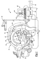
[0022]図1は、様々な処置に使用することができるナビゲーションシステム10の概要を示す図である。ナビゲーションシステム10は、患者14などの被験体に対する、移植片または機器(本明細書にて考察するようなもの)などの物品の位置を追跡するのに使用することができる。更に、ナビゲーションシステム10は、ガイドワイヤ、関節鏡システム、整形外科移植片、脊椎移植片、脳深部刺激(DBS)リード線、心臓ペーシングリード線、アブレーション機器など、任意のタイプの機器、移植片、または送達システムをナビゲートするのに使用されてもよいことに留意すべきである。更に、機器は、身体の任意の領域をナビゲートまたはマッピングするのに使用されてもよい。ナビゲーションシステム10および様々な追跡された物品は、一般的に低侵襲性のものまたは開放処置など、任意の適切な処置で使用されてもよい。
[0020] Corresponding reference numerals indicate corresponding parts throughout the several views.
[0021] In the following, exemplary embodiments will be described more fully with reference to the accompanying drawings.
[0022] FIG. 1 is an overview of a
[0023]ナビゲーションシステム10は、術前、術中、もしくは術後、またはリアルタイムの患者14の画像データを獲得するのに使用される、撮像システム12とインターフェース接続することができる。任意の適切な被験体を撮像することができ、任意の適切な処置が被験体に対して実施されてもよいことが、当業者には理解されるであろう。被験体はヒトの患者であってもよく、処置は、デバイス(例えば、ねじ、リード線など)の埋込みなどの外科処置であってもよい。
[0023] The
[0024]図1に例示的に示されるように、撮像システム12は、米国コロラド州ルイビル(Luisville,Colorado,USA)所在のMedtronic Navigation,Inc.によって販売されている、Oアーム(登録商標)撮像デバイスを含む。撮像デバイス12は、画像キャプチャ部分22を包囲する、ほぼ環状のガントリハウジング20を有してもよい。画像キャプチャ部分22は、ガントリハウジング20内で互いからほぼもしくは事実上可能な180度に位置する、X線源または放射部分26およびX線受信または画像受信部分28を含んでもよい。様々な実施形態では、X線源または放射部分26およびX線受信または画像受信部分28は、ほぼ環状のガントリハウジング20内のトラック(図示なし)に対してロータ(図示なし)に装着されてもよい。画像キャプチャ部分22は、画像獲得中に360度回転するように動作可能であってもよい。画像キャプチャ部分22は、中心点または中心軸を中心にして回転してもよく、それによって患者14の画像データを複数の方向から、または複数の面内で獲得することが可能になる。撮像システム12は、米国特許第7,188,998号、第7,108,421号、第7,106,825号、第7,001,045号、および第6,940,941号に開示されているものを含むことができ、それら全てを参照により本明細書に援用する。しかしながら、撮像システム12はまた、やはり患者14の三次元像を生成することができる、Cアーム蛍光画像診断システム、コンピュータ断層撮影(CT)画像診断システムなど、他の撮像システムを含むか、またはそれらと置き換えられてもよい。
[0024] As exemplarily shown in FIG. 1, the
[0025]画像キャプチャ部分22の位置は、撮像デバイス12の他の任意の部分に対して正確に分かっている場合がある。それに加えて、本明細書で考察するように、画像キャプチャ部分22の位置の正確な認識を、追跡システム29と併せて使用して、追跡されている患者14などの被験体に対する、画像キャプチャ部分22および画像データの位置を判定することができる。例えば、患者追跡デバイス48は、患者14を追跡するのに、患者14上に配置されてもよい。
The position of the
[0026]追跡システム29は、ナビゲーションシステム10と関連付けられるかそれとともに含まれる様々な部分を含むことができる。追跡システム29はまた、光学ローカライザ40を含む光学追跡システム、および/またはEMローカライザ42を含むことができる電磁(EM)追跡システムを含む、複数のタイプの追跡システムを含むことができる。光学ローカライザ40は、カメラを用いて追跡可能部分(追跡デバイス)を「見る」かまたは光学的に追跡してもよい。EMローカライザ42はフィールドを生成してもよく、また追跡可能部分(例えば、EM追跡デバイス)は、そのフィールドを感知して、フィールド内の別の追跡デバイスに対する場所を判定してもよい。本明細書で更に考察するものを含む様々な追跡デバイスは、追跡システム29を用いて追跡することができ、情報をナビゲーションシステム10が使用して、物品の位置の表示を可能にすることができる。概して、患者追跡デバイス48、撮像デバイス追跡デバイス50、および機器追跡デバイス52などの追跡デバイスによって、光学ローカライザ40および/またはEMローカライザ42を含む適切な追跡システム29を用いて、手術室の選択された部分を互いに対して追跡することが可能になる。
[0026]
[0027]それぞれの追跡デバイスを追跡するのに使用される追跡ローカライザに応じて、追跡デバイス48〜52のうち任意のものは、光学もしくはEM追跡デバイス、または両方であり得ることが理解されるであろう。更に、任意の適切な追跡システムをナビゲーションシステム10とともに使用できることが理解されるであろう。代替の追跡システムとしては、レーダー追跡システム、音響追跡システム、超音波追跡システムなどを挙げることができる。
[0027] It is understood that any of the tracking devices 48-52 may be optical or EM tracking devices, or both, depending on the tracking localizer used to track each tracking device. I will. Further, it will be appreciated that any suitable tracking system can be used with the
[0028]例示のEM追跡システムとしては、コロラド州ルイビル(Louisville,Colorado)所在のMedtronic Navigation,Inc.によって販売されている、STEALTH STATION(登録商標)AXIEM(商標)Navigation Systemを挙げることができる。例示の追跡システムはまた、米国特許第8,644,907号、23012年2月4日発行、名称「Method And Apparatus For Surgical Navigation(外科的ナビゲーションの方法および装置)」、米国特許第7,751,865号、名称「Method And Apparatus For Surgical Navigation(外科的ナビゲーションの方法および装置)」、2010年7月6日発行、米国特許第5,913,820号、名称「Position Location System(位置決めシステム)」、1999年6月22日発行、および米国特許第5,592,939号、名称「Method and System for Navigating a Catheter Probe(カテーテルプローブをナビゲートする方法およびシステム)」、1997年1月14日発行に開示されており、全てを参照により本明細書に援用する。 [0028] Exemplary EM tracking systems include Medtronic Navigation, Inc., located in Louisville, Colorado. Mention may be made of the STEALTH STATION® AXIEMTM Navigation System, marketed by An exemplary tracking system is also described in U.S. Patent No. 8,644,907, issued February 4, 23012, entitled "Method And Apparatus For Surgical Navigation", U.S. Patent No. 7,751. No. 865, entitled "Method And Apparatus For Surgical Navigation", issued July 6, 2010, U.S. Pat. No. 5,913,820, entitled "Position Location System". , June 22, 1999, and U.S. Patent No. 5,592,939, entitled "Method and System for Navigating a Cathet". r Probe (method and system for navigating a catheter probe) ", it is disclosed in published Jan. 14, 1997, incorporated herein by reference in their entirety.
[0029]更に、EM追跡システムの場合、EMローカライザ42によって生成されるEMフィールドにおける歪みを遮蔽または補償する、遮蔽または歪み補償システムを提供するのが必要なことがある。例示的な遮蔽システムとしては、米国特許第7,797,032号、名称「Method and system for navigating a catheter probe in the presence of field−influencing objects(フィールドに影響する物体の存在下でカテーテルプローブをナビゲートする方法およびシステム)」、2010年9月14日発行、および米国特許第6,747,539号、名称「Patient−shielding and coil system(患者遮蔽およびコイルシステム)」、2004年6月8日発行のものが挙げられ、それら全てを参照により本明細書に援用する。歪み補償システムとしては、米国特許第6,636,757号、名称「Method and apparatus for electromagnetic navigation of a surgical probe near a metal object(金属物の付近における外科用プローブの電磁ナビゲーションの方法および装置)」、2003年10月21日発行に開示されているものを挙げることができ、その全てを参照により本明細書に援用する。 [0029] Further, in the case of an EM tracking system, it may be necessary to provide a shielding or distortion compensation system that shields or compensates for distortion in the EM field generated by the EM localizer 42. As an exemplary shielding system, see US Pat. No. 7,797,032 entitled “Method and system for navigating a catheter probe in the presence of field-influencing objects (navigating a catheter probe in the presence of an object affecting the field) Methods and Systems for Gating ", published 14 September 2010, and U.S. Patent No. 6,747,539, entitled" Patient-shielding and coil system ", 8 June 2004 Publications are included, all of which are incorporated herein by reference. As a distortion compensation system, US Pat. No. 6,636,757, entitled "Method and apparatus for electromagnetic navigation of a surgical probe of a surgical object (a method and apparatus for electromagnetic navigation of a surgical probe in the vicinity of a metal object)" No. 10, October 21, 2003, all of which are incorporated herein by reference.
[0030]EM追跡システム、EMローカライザ42、および様々な追跡デバイスは、EMコントローラ44を通して通信することができる。EMコントローラは、様々な増幅器、フィルタ、電気絶縁、および他のシステムを含むことができる。EMコントローラ44はまた、ローカライザ42のコイルを制御して、追跡用にEMフィールドを放射または受信することができる。しかしながら、EMコントローラ44に直接連結するのとは対照的に、本明細書に参照により援用する、米国特許第6,474,341号、名称「Surgical Communication Power System(外科用通信電源システム)」、2002年11月5日発行に開示されているものなど、無線通信チャンネルを使用することができる。
[0030] The EM tracking system, the EM localizer 42, and various tracking devices can communicate through the
[0031]追跡システムはまた、コロラド州ルイビル(Louisville,Colorado)所在のMedtronic Navigation,Inc.によって販売されている、光学ローカライザ40に類似した光学ローカライザを有する、STEALTHSTATION(登録商標)TRIA(登録商標)、TREON(登録商標)、および/またはS7(商標)Navigation Systemを含む、任意の適切な追跡システムであるかまたはそれを含んでもよいことが理解されるであろう。光学追跡システムはまた、米国特許第8,010,177号、2011年8月30日発行、「Intraoperative Image Registration(術中画像の位置合わせ)」、米国特許第6,235,038号、2001年5月22日発行、名称「System For Translation Of Electromagnetic And Optical Localization Systems(電磁および光学ローカライゼーションシステムの変換システム)」に開示されているものを含んでもよく、全てを参照により本明細書に援用する。更なる代替の追跡システムが、米国特許第5,983,126号、Wittkampfら、名称「Catheter Location System and Method(カテーテル配置システムおよび方法)」、1999年11月9日発行に開示されており、それを参照により本明細書に援用する。他の追跡システムとしては、音響、放射線、レーダーなどの追跡またはナビゲーションシステムが挙げられる。 [0031] The tracking system is also described in Medtronic Navigation, Inc., Louisville, Colo. Any suitable, including STEALTHSTATION (R) TRIA (R), TREON (R), and / or S7 (TM) Navigation System, having an optical localizer similar to optical localizer 40 sold by It will be appreciated that it may be or include a tracking system. Optical tracking systems are also described in U.S. Patent No. 8,010,177, issued August 30, 2011, "Intraoperative Image Registration", U.S. Patent No. 6,235,038, 2001 5 May 22 issue, entitled "System For Translation Of Electromagnetic And Optical Localization Systems (Transformation system for electromagnetic and optical localization systems)", all of which are incorporated herein by reference. A further alternative tracking system is disclosed in US Pat. No. 5,983,126, Wittkampf et al., Entitled "Catheter Location System and Method", issued November 9, 1999, It is incorporated herein by reference. Other tracking systems include acoustic, radiation, radar or other tracking or navigation systems.
[0032]撮像システム12は、支持ハウジングまたはカート56を含むことができる。撮像システム12は、カート56に収容することができる別個の画像処理装置58を更に含むことができる。ナビゲーションシステム10は、ナビゲーションメモリ62と通信するかまたはそれを含むことができる、ナビゲーション処理装置60を含むことができる。ナビゲーション部材62は、ランダムアクセスメモリ、磁気媒体ドライブなどを含む、任意の適切な非一時的メモリを含んでもよい。更に、ナビゲーションメモリ62は、ナビゲーション処理装置60と統合されるか、またはナビゲーション処理装置60と離れていてもよい。ナビゲーション処理装置60は、画像データを含む情報を撮像システム12から、また追跡情報を、それぞれの追跡デバイス48〜52およびローカライザ40〜42を含む追跡システム29から受信することができる。画像データは、ワークステーションまたは他のコンピュータシステム68の表示デバイス66上に、画像64として表示することができる。ワークステーション68は、キーボード70などの適切な入力デバイスを含むことができる。マウス、フットペダルなど、他の適切な入力デバイスが含まれ得ることが理解されるであろう。様々な処理装置およびコンピュータまたはワークステーションは、内部またはローカルメモリおよび処理装置を含んでもよい。処理装置は、命令を実行してチップ上のタスクを実施する汎用コンピュータである、中央処理装置を含んでもよい。処理装置はまた、特定用途向け集積回路(ASIC)などの専用回路であってもよい。したがって、処理装置は、情報を受信し、情報に基づいて格納または受信された命令を実行するデバイスであってもよい。
[0033]画像処理装置58は、撮像システム12からの画像データを処理し、それをナビゲーション処理装置60に送信する。しかしながら、撮像システム12は何らかの画像処理を実施しなくてもよく、画像データをナビゲーション処理装置60に直接送信できることが更に理解されるであろう。したがって、ナビゲーションシステム10は、システム設計に応じて、単一もしくは複数のメモリシステムにアクセスすることができる、単一もしくは複数の処理センタまたは処理装置を含むか、あるいはそれとともに動作してもよい。
[0034]患者14は、手術台72上に固定することができるが、台72に固定されるのは必須ではない。台72は複数のストラップ74を含むことができる。ストラップ74を患者14の周りでしっかり固定して、患者14を台72に対して固定することができる。様々な装置が、患者14を手術台72上において静止位置で位置付けるのに使用されてもよい。かかる患者位置付けデバイスの例は、同一出願人による、米国特許出願公開第2004/0199072号として公開された米国特許出願第10/405,068号、名称「An Integrated Electromagnetic Navigation And Patient Positioning Device(統合型電磁ナビゲーションおよび患者位置付けデバイス)」、2003年4月1日出願に説明されており、それを参照により本明細書に援用する。他の知られている装置は、Mayfield(登録商標)クランプを含んでもよい。
The patient 14 may be fixed on the operating table 72, but it is not necessary to be fixed to the table 72. The
[0035]また、撮像システム12に対する患者14の位置(三次元位置および配向を含む)は、患者追跡デバイス48および撮像システム追跡デバイス50を用いてナビゲーションシステム10によって判定することができる。本明細書で考察するように、患者14に対する位置(三次元位置および配向を含む)は、少なくとも部分的に、患者14の獲得画像を用いて判定されてもよい。したがって、撮像システム12に対する患者14の位置(三次元位置および配向を含む)を判定することができる。Oアーム(登録商標)などの撮像システム12は、その位置を知ることができ、約10ミクロン以内で同じ位置に再位置付けすることができる。これによって、撮像システム12の実質的に正確な配置、および撮像デバイス12の位置の正確な判定が可能になる。撮像部分22の正確な位置付けは、米国特許第7,188,998号、第7,108,421号、第7,106,825号、第7,001,045号、および第6,940,941号に更に記載されており、それら全てを参照により本明細書に援用する。一般に、患者14に対する画像データの位置を判定するように選択されてもよい。例えば、患者に対する配向を含む画像データの位置は、患者14の一部分の場所を判定するのに使用されてもよい。
Also, the position (including three-dimensional position and orientation) of the patient 14 relative to the
[0036]被験体または患者空間および画像空間は、患者空間における整合点または基準点、および画像空間における関連または同一点を特定することによって、位置合わせすることができる。Medtronic,Inc.によって販売されているOアーム(登録商標)撮像デバイスなどの撮像デバイス12を使用して、正確な分かっている位置で画像データを生成することができる。これによって、画像データを獲得する際に、画像データを患者14に対して自動的にまたは「固有に」位置合わせするのを可能にすることができる。本質的に、患者14に対する撮像システム12の精密な位置付けにより、患者14の位置は撮像システム12に対して正確に分かっている。これにより、撮像システム12の分かっている正確な位置のため、患者14の点に対して画像データ中の点を知ることが可能になる。
[0036] The subject or patient space and the image space can be registered by identifying matching or reference points in the patient space and related or identical points in the image space. Medtronic, Inc. An
[0037]あるいは、画像データ中の基準点を患者14上の基準点と整合させることによって、手動または自動の位置合わせを行うことができる。患者空間に対する画像空間の位置合わせによって、患者空間と画像空間との間の変換マップを生成することが可能になる。様々な実施形態によれば、画像空間および患者空間内で実質的に同一である点を判定することによって、位置合わせを行うことができる。同一点は、解剖学的基準点または埋込み基準点を含むことができる。例示の位置合わせ技術は、現在は公開されている米国特許出願公開第2010/0228117号である、第12/400,273号、2009年3月9日出願に開示されており、参照により本明細書に援用する。
Alternatively, manual or automatic registration can be performed by aligning reference points in the image data with reference points on the
[0038]一旦位置合わせされると、撮像システム12を有するかまたは含むナビゲーションシステム10を、選択された処置を実施するのに使用することができる。選択された処置は、撮像システム12を用いて生成または獲得された画像データを使用することができる。更に、撮像システム12は、処置に関して異なる時間に画像データを獲得するのに使用することができる。本明細書で考察するように、処置の部分の確認を含む様々な目的で、処置の選択された部分に続いて、患者14の画像データを獲得することができる。
[0038] Once aligned, the
[0039]図1を引き続き参照すると、撮像システム12は、患者14の実際または仮想の三次元画像を生成することができる。患者14は、撮像システム12が患者14の画像データを取得することが可能になるように、撮像システム12に対して配置することができる。3D画像データを生成するため、患者14に対する複数の視野または位置から画像データを獲得することができる。患者14の3D画像データを、単独でまたは他の情報とともに使用して、患者14または適切な被験体に対する処置の実施を支援することができる。しかしながら、磁気共鳴イメージング、コンピュータ支援断層撮影、蛍光透視法などを含む、任意の適切な撮像システムを使用して、患者14の画像データ(3D画像データを含む)を獲得できることが理解されるであろう。
With continued reference to FIG. 1,
[0040]図2をまず参照すると、フローチャート100は、図3〜10に示されるような、埋込み処置後の移植片の配置を確認する方法を示している。しかしながら、フローチャート100は、椎骨124に1つまたは複数の椎弓根スクリュー120を含む、脊椎移植片を配置する方法を説明しており、それを対象としていることが理解されるであろう。しかしながら、方法100は、長骨(例えば、大腿骨)の髄内(IM)ロッド、膝もしくは臀部置換人工器官、または他の適切な処置など、解剖学的構造の任意の適切な位置における任意の適切な移植片の配置を確認するのを支援するため、画像データを獲得するのに使用されてもよい。したがって、フローチャート100の方法は、椎弓根スクリュー配置を越える選択された処置を包含することが理解されるであろう。それに加えて、フローチャート100の方法は、任意の適切な構造における任意の適切な部材の配置を確認するのに使用することができることが理解されるであろう。例えば、放射線透過性作業片(例えば、木板)内へのスパイクを含む部材の配置も、フローチャート100の方法を用いて確認することができる。
[0040] Referring first to FIG. 2, a flowchart 100 illustrates a method of confirming the placement of the implant after the implantation procedure, as shown in FIGS. However, it will be understood that the flowchart 100 describes and is directed to a method of placing a spinal implant including one or
[0041]フローチャート100の方法は、開始ブロック102で始めることができる。次に、処置をブロック104で選択することができる。処置は、患者14の椎骨124(図6)内における椎弓根スクリューの配置など、任意の適切な処置であることができる。患者14の椎骨124への椎弓根スクリュー120の配置は、脊椎固定または椎骨硬直(vertebral rigidity)などの任意の適切な処置のために実施できることが理解されるであろう。ブロック104で選択される処置にかかわらず、被験体14の第1の画像データをブロック106で獲得することができる。しかしながら、第1の画像データは、実施される処置を決定する前に獲得されてもよい。例えば、ブロック106で獲得される第1の画像データは、ブロック104で処置を選択、確認、および/または計画するのに使用される、初期診断画像データであってもよい。したがって、第1の画像データは、処置前または獲得前画像データであってもよい。第1の画像データは、ブロック104から選択された処置を実施する前の患者14の画像データである。
[0041] The method of flowchart 100 can begin at
[0042]ブロック104で実施される処置を選択する際、当業者には理解されるように、手術計画が生成されてもよい。手術計画は、進入位置、移植片(例えば、椎弓根スクリュー)の埋込みの軌道、処置を実施する機器の選択、ならびに処置に関する他の適切な選択およびステップの選択を含んでもよい。しかしながら、処置は、必ずしも外科処置でなくてもよく、機械的アセンブリ(例えば、自動車)の設置または組立てなど、他の選択された処置を実施する計画を含んでもよい。
[0042] In selecting the treatment to be performed at
[0043]ブロック106で獲得された画像データは、図3に上からの視点で示される、単一の椎骨のX線画像データなど、任意の適切な画像データであることができる。画像データはまた、横の視点から見た、図4に示されるような、複数の椎骨の画像を含んでもよい。更に、画像データは、図5に示されるように、複数の椎骨の後ろからの視点を含んでもよい。画像データは、画像64a、64b、64cとしてそれぞれディスプレイ66に表示することができ、または獲得してナビゲーションシステム10のメモリもしくは記憶システム62に保存することができ、処置を後で確認するのに使用することができ、または両方に使用することができる。
[0043] The image data acquired at
[0044]概して、被験体の第1の画像データは、外科的介入の任意の部分が実施される前に獲得される、被験体または患者14の画像データであることができる。例えば、患者14は、実質的に手術室に入った直後に、また切開の形成など任意の外科処置を実施する前に、撮像システム12を用いて撮像することができる。更に、ブロック106で獲得される被験体の第1の画像データは、患者14が手術室に入る前の任意の時点で獲得できることが理解されるであろう。第1の画像データを獲得するタイミングにかかわらず、第1の画像データは、外科処置によって変更されていないなど、第1の状態にある患者または被験体14の画像データである。本明細書で更に考察するように、フローチャート100の方法に関連して、この画像データを、患者14内における移植片の配置を確認するのに、後のまたは第2の獲得画像データ、および移植片のモデル(例えば、CADモデル)とともに使用することができる。
[0044] Generally, the first image data of the subject can be image data of the subject or
[0045]しかしながら、上述したように、ブロック106で獲得される画像データは、患者14に対する選択位置で獲得することができる。図1に示されるように、患者トラッカー48を用いて患者14で可能なように、撮像デバイス追跡デバイス50を追跡することができる。したがって、患者14に対する撮像デバイス12の位置は、ブロック106で第1の画像データを獲得するときに、ナビゲーションシステム10を用いて判定することができる。この第1の撮像位置はブロック109で保存されてもよい。ブロック109で保存されるこの第1の撮像デバイス位置は、患者14に対して獲得される各画像部分の離散的な位置(場所および配向を含む)を含んでもよい。例えば、複数の露出が獲得されてもよく、各露出は患者14に対する異なる位置におけるものであってもよい。したがって、ブロック109で保存される第1の画像装置位置は、第1の画像データとともに獲得される撮像デバイス12の各露出の位置を含んでもよい。これらの位置は、ナビゲーションメモリ62に保存されるなど、後で呼び出すために保存されてもよい。
However, as mentioned above, the image data acquired at
[0046]第1の画像データがブロック106で獲得された後、第1の画像データは、任意に、ブロック112でデータプロセッサに転送することができる。ブロック112でデータプロセッサに転送される画像データは、ブロック106からの第1の画像データにおいて獲得される患者14の全ての第1の画像データであることができる。ブロック106からの第1の画像データは、被験体14の二次元(2D)投影として見られてもよく、または被験体14の三次元(3D)モデルを生成するのに使用されてもよい。例えば、1つまたは複数の2D投影は、ブロック112で処理されて、被験体14の3Dモデルを生成してもよい。それにより、モデルは、ディスプレイ上の画像として見られてもよい。更に、処置は3Dモデルを用いて計画されてもよく、計画の少なくとも一部分(例えば、部材の選択された最終埋込み場所)が、3Dモデルおよび/または2D投影上に重ねあわされたアイコンとして例示されてもよい。図3〜5に示されるように、患者14の画像データは複数の観点または視点から獲得することができる。
After the first image data is acquired at
[0047]ブロック106で獲得された第1の画像データは、任意の適切な処理コアもしくはシステムに保存または転送することができ、あるいは単に、単一の処理装置によってアクセスされるように直接転送または維持することができる。上述したように、撮像処理装置58は撮像システム12に組み込むことができ、ナビゲーションプロセッサ60はナビゲーションワークステーション68を含むことができる。したがって、2つの処理装置は通信することができ、画像データをそれらの間で転送することができる。あるいは、単に画像データを獲得し、ナビゲーションプロセッサ60に転送することができる。それにもかかわらず、ナビゲーションシステム10は、当業者には理解されるように、単一もしくは複数の処理装置またはコアを用いて画像データを処理できることが理解されるであろう。
[0047] The first image data acquired at
[0048]第1の画像データがブロック106で獲得され、任意にブロック112でプロセッサに転送されると、選択された処置をブロック114で実施することができる。図6に示されるように、処置は、患者14内への椎弓根スクリュー120の配置を含むことができる一般に理解されるように、患者14の解剖学的構造は椎骨124を含むことができ、その中に椎弓根スクリュー120を位置付けるかまたは埋め込むことができる。椎弓根スクリュー120は、外科用モータ126などの適切な外科用機器を用いて埋め込むことができ、またはミネソタ州ミネアポリス(Minneapolis,MN)所在のMedtronic Spine and Biologiesによって販売されている、CD Horizon(登録商標)Legacy(商標)System手動ドライバなどの適切な手動ドライバ(図示なし)を用いて埋め込むことができる。椎弓根スクリュー120を埋め込むのに使用される機器にかかわらず、機器および/または椎弓根スクリュー120は追跡デバイス52を含むことができる。追跡デバイス52は、外科処置中に、光学ローカライザ40またはEMローカライザ42を含む追跡システムのどちらかもしくは両方を用いてなど、ナビゲーションシステム10によって追跡することができる。
[0048] Once the first image data is acquired at
[0049]追跡デバイス52によって、ナビゲーションシステム10が、獲得された患者14の画像データに対する、椎弓根スクリュー120、埋込み機器126、またはそれらの組み合わせの位置を判定し例示することが可能になる。例えば、図7に示されるように、椎弓根スクリュー120の1つまたは複数を患者14の椎骨124に向かって移動させるにつれて、1つまたは複数のアイコン120iを、患者14の第1の獲得した画像データ64a、b、c上に重ね合わせることができる。上述したように、椎弓根スクリュー120または他の適切な移植片部材の1つもしくは複数が、患者14内まで追跡されてもよい。更に、追跡される機器または物品は、必ずしも移植片または硬組織移植片でなくてもよいが、軟組織移植片(例えば、DBSリード線)を含んでもよい。埋込み中または埋込み後など、任意の適切な時間における椎弓根スクリュー120の判定された位置は、後で呼び出すために、ナビゲーションメモリ62または他の適切なメモリシステムに保存されてもよい。次に、椎弓根スクリュー120の判定および/または保存された位置が、本明細書で考察するように、選択された処置の確認または選択された(例えば、外科)処置の計画に使用されてもよい。
[0049] The
[0050]図6に示されるように、椎弓根スクリュー120が椎骨124に向かってその中へと移動するにつれて、アイコン120i(図7)を画像66に対して例示することができる。図6は、椎骨124に挿入する前の椎弓根スクリュー120の単一のものを示しており、図7は、単一の椎骨124の画像124’内に配置される2つの個々の椎弓根スクリューを示すために2つのアイコン120iを示していることが、当業者には理解される。
[0050] As shown in FIG. 6, an icon 120i (FIG. 7) may be illustrated for the
[0051]アイコン120iは、椎弓根スクリュー120などの移植片の、アプリオリの正確な寸法情報を含むねじの事前形成モデル(コンピュータ支援製図図形など)であることができる。事前形成モデルは、ナビゲーションメモリデバイス62に保存することができ、ナビゲーションプロセッサ60などの適切なプロセッサによってアクセスすることができる。しかしながら、移植片の寸法は、追跡可能な校正機器の測定または使用などによって、処置の間に判定できることが理解される。次に、寸法はナビゲーションシステム10に入力されてもよい。しかしながら、更に、ナビゲーションは処置を実施するのに必須ではないことが理解されるであろう。例えば、低侵襲性または開放処置が、ナビゲーション支援を用いずに移植片を配置するのに使用されてもよい。また、椎骨の画像データ64aは、画像データ64aに対して自動または手動で決定することができる中心線アイコン140など、他の情報を含むことができることが理解されるであろう。
[0051] The icon 120i can be a pre-formed model of a screw (such as a computer aided drawing diagram) that includes a priori accurate dimensional information of an implant, such as a
[0052]ナビゲーションシステム10は、直接またはナビゲートされた機器を通して椎弓根スクリュー120を追跡することによって、椎骨124に対する椎弓根スクリュー120の判定された位置(場所および配向を含む)を例示するのに使用することができる。患者14の画像データ64a、b、c上に重ね合わされたアイコン120iを例示することによって、ユーザ54は、患者14および椎骨124に対する椎弓根スクリュー120の位置をガイドするか、またはそれに関するフィードバックを得ることができる。したがって、選択された時間に、ユーザは、アイコン120iの位置または他の適切な情報に基づいて、患者14の椎骨124内への椎弓根スクリュー120の推進を停止するように選択することができる。その後、椎弓根スクリュー120が追跡システムまたはナビゲーションシステム10によって直接追跡されないとき、追跡されたアイコン120iを除去することができる。椎弓根スクリュー120の位置は、本明細書で考察するように、画像データに基づいて直接判定されてもよい。
[0052] The
[0053]一般に、撮像システム12は、ブロック106で第1の画像データを獲得し、ブロック114で処置を実施した後の、患者14に対する位置から移動される。例えば、撮像デバイス12は、椎弓根スクリュー120を埋め込むために椎骨124へのアクセスを可能にするように移動される。しかしながら、撮像デバイス12は、他の任意の適切な理由で移動されてもよい。更なる一例として、撮像デバイス12は、DBS配置のために頭蓋に更にアクセスできるように移動されてもよい。しかしながら、撮像システム12を移動させた場合であっても、椎弓根スクリュー120または他の部材の場所はナビゲートされた空間内で保存されてもよいことが理解される。例えば、患者とラッカー48に対する患者スクリュー120の位置は、ナビゲーション処理装置、または他の適切な処理装置によって呼び出すために保存されてもよい。椎弓根スクリュー120の位置は、例えば、埋込み後または第2の画像データの獲得前など、選択された期間の後に保存されてもよい。その後、椎弓根スクリュー120の保存された位置は、例えば、撮像システム12を位置付けて第2の画像データを獲得するために呼び出されてもよい。
[0053] In general,
[0054]いずれにせよ、第2の画像データが取得される場合、撮像デバイス12を患者14に対して移動させるのが必要なことがある。例えば、撮像デバイス12が患者14の脊椎の一部分をもう取り囲んでいない場合、撮像デバイスを移動させて、脊椎の一部分を取り囲むように戻してもよい。しかしながら、患者14が露出される放射線を最小限に抑えるように選択されてもよく、ならびに/あるいはそれが望ましいことがある。第2の画像データは、一般に、計画された処置を確認するために獲得されるので、患者14に対する全360度の露出は必須ではないことがある。したがって、本明細書で考察するように、ブロック106で獲得される第1の画像データよりも患者14に対する露出が少なくなる画像データを獲得するのに、撮像デバイス12を患者14に対して移動させてもよい。例えば、画像処理装置58および/またはナビゲーション処理装置60などを用いた判定。
[0054] In any event, it may be necessary to move
[0055]したがって、ユーザ54が、椎骨124内への椎弓根スクリュー120の推進を停止するように決定すると、被験体14の第2の画像データをブロック150で獲得できるか否かの判定が行われる。獲得された患者14の第2の画像データは、椎弓根スクリュー120が選択された量または距離まで椎骨124内に位置付けられた後、撮像システム12または任意の適切な撮像システムを用いて獲得される、患者14の画像データであることができる。
[0055] Thus, if the
[0056]ユーザ54によって使用される、第2の画像データが、本明細書で考察するように示されてもよい。第2の画像データはまた、移植片のモデルなどの様々な情報を用いて増補されてもよい。例えば、第2の画像データは、参照により本明細書に援用する、米国特許第8,842,893号、2013年9月23日発行、名称「Method and Apparatus For Image−Based Navigation(画像に基づいたナビゲーションの方法および装置)」に開示されているような、追跡情報に基づいて画像データ上に重ね合わされる移植片のモデルを有してもよい。上述したように、移植片のモデルはナビゲーションを支援するのに使用されてもよい。更に、移植片の選択された測定値が獲得されてもよい。いずれにせよ、患者14の画像データは、患者14に対して実施される処置の実施および/または確認を支援するのに使用されてもよい。
[0056] The second image data used by
[0057]図2を引き続き参照すると、ブロック150で第2の画像データを獲得するか否かの判定は、処置の確認、移植片の現在の場所(例えば、椎弓根スクリュー120の位置)の判定、更なる処置ステップの判定、または他の適切な理由を含む、様々な目的であってもよい。一例として、以下の考察では、移植片120が椎骨124内の計画位置に達しているかまたは位置付けられているかを確認することが選択されてもよい。しかしながら、確認画像データが不要であることが望ましいからまたは判定された場合、ブロック152を通る「いいえ」の経路を辿ってもよく、プロセスはブロック154で終了してもよい。例えば、開放処置が実施される場合、選択された時間における確認画像は選択されないかまたは不要であってもよい。更に、被験体14の第2の画像データの獲得を含まない、他の確認技術が用いられてもよい。
[0057] Continuing to refer to FIG. 2, the determination of whether to acquire the second image data at
[0058]いずれにせよ、第2の画像データはブロック150で選択されてもよく、「はい」のブロック160を通って「はい」の経路を辿ることができる。ブロック150の判定は、自動であるかまたはユーザの入力によってもよい。例えば、処置は、ナビゲーション処理装置60によるプログラムとして含まれてもよく、第2の画像データに対するプロンプトが与えられてもよい。
[0058] In any case, the second image data may be selected at
[0059]しかしながら、ブロック150から、「はい」のブロック160が判定された後、ブロック162で患者トラッカー48が患者14に取り付けられるか否かの判定ブロックが判定されてもよい。ブロック162で患者トラッカーがまだ取り付けられているか否かの判定も、手動または自動であってもよい。例えば、ユーザ54は、患者トラッカーが取り付けられているキーボード70などを使用して、システムに入力してもよい。更に、またはその代わりに、追跡システム29およびナビゲーションシステム10などを含むシステムは、信号が患者14に取り付けられた患者トラッカー48から受信されているか測定されているか否かを判定することができる。患者トラッカー48がまだ取り付けられていると判定された場合、「はい」のブロック163を通って「はい」の経路を辿る。追跡システム29およびナビゲーションシステム10は、撮像システム追跡デバイス50などを用いて、患者14および撮像システム12を追跡することができる。追跡の際、したがって、ナビゲーションシステム10は、確認画像データを含む追加の画像データを獲得するなど、様々な目的で、患者14および撮像システム12の位置を判定してもよい。更に、上述したように、移植片、例えば椎弓根スクリュー120の位置は、処置中に機器トラッカー52などを用いて、椎弓根スクリュー120の位置を追跡することによって判定されていてもよい。したがって、移植片120の位置は、ナビゲーションメモリ62から分かり、呼び出すことができる。椎弓根スクリューの保存された位置は、埋込み中に椎弓根スクリュー120が追跡され、椎弓根スクリュー120の位置がナビゲーションメモリ62に保存されたときのものであってもよい。
However, from
[0060]図1に示されるように、撮像デバイス12を患者14に対して位置付けて、ブロック106で、第1の画像データを獲得することができる。しかしながら、椎弓根スクリュー120の配置などの処置を実施する際、撮像デバイス12は患者14から離れる方向に移動されてもよい。患者14から離れる方向に移動させる場合、第2の画像データを獲得するため、患者14は撮像デバイス12に対して再位置付けされる。一般に、撮像デバイス12を移動させて患者14に近付けてもよく、または患者14を移動させて撮像デバイス12に近付けてもよい。移動中、患者14に対する撮像デバイス12の正確な位置付けは、第1の画像データを獲得したときから変更されてもよい。
[0060] As shown in FIG. 1, the
[0061]患者14、または患者14の少なくとも関心部分もしくは関心のある解剖学的構造の三次元モデルは、第1の画像データからディスプレイ66上で見るために作成されてもよい。したがって、第1の画像データは、患者14の三次元モデルを生成するのに十分な画像データを獲得するために、患者14を通る多数の投影(例えば、一般にそれぞれ異なる位置で獲得された、約300〜約700個の投影)を要することがある。しかしながら、第2の画像データを獲得するときは、第1の画像データを獲得したときほど多くの投影は必要でないことがあり、または第1の画像データを獲得したときほど多くの投影を獲得するように選択されないことがある。第2の画像データは、移植片配置の検証または確認、およびモデル作成のために選択されてもよく、したがって必要な画像データはより少ないことがある。したがって、患者14を通る最小限の投影を獲得することで、患者14およびユーザ54が経験する放射線量を最小限に抑えるかまたは低減することができる。
[0061] The
[0062]したがって、第2の画像データは、患者14を通る選択された数または最小限の投影が作られてもよいことを選択することを含んでもよい。第2の画像データは、確認または検証画像データと呼ばれることもある。したがって、第2の画像データを獲得する画像デバイスの適切なまたは最良の位置の判定は、必要な投影または視野の数を最小限に抑えることを支援してもよい。各投影は、被験体14の画像データを獲得するのに、X線放射などの放射線に対する露出を要することがある。特に、撮像デバイス12は、第2の画像データの視野を獲得して、2つを含む少数など、選択された数の患者14を通る投影を用いて、椎弓根スクリュー120などの埋め込まれた部材の位置を判定するように操作されてもよい。獲得された第2の画像データから判定した移植片の位置を使用して、本明細書で考察するように、それから生成される第1の獲得画像データまたはモデル上に重ね合わせるアイコンを生成することができる。
Thus, the second image data may include selecting that a selected number or minimal projection through the patient 14 may be made. The second image data may be referred to as verification or verification image data. Thus, determination of the proper or best position of the imaging device to acquire the second image data may help minimize the number of projections or views required. Each projection may require exposure to radiation, such as x-ray radiation, to acquire image data of
[0063]患者追跡デバイス48を用いた患者14の追跡を維持することによって、追跡デバイス50を用いて撮像デバイス12を追跡して、患者14に対して撮像デバイス12を位置付けて、最小限のまたは選択された数の投影を獲得するとともに、移植片120を適切に見るのに十分な画像データを獲得することができる。例えば、ブロック164で、ブロック106から第1の画像データを獲得している間、撮像デバイスの位置の呼出しが行われてもよい。
[0063] By keeping track of the patient 14 with the patient tracking device 48, the
[0064]ブロック164からの撮像デバイスの呼び出された位置は、ブロック165で第2の画像データを獲得するための撮像デバイスの1つまたは複数の位置を判定するのを支援してもよい。特に、撮像デバイス12および患者14の相対位置が、第2の画像データを獲得するために判定されてもよい。相対位置は、ブロック164から第1の画像データを獲得するのに呼び出された位置に基づいてもよい。更に、ブロック165で第2の画像データを獲得するのに相対位置を判定する際、椎弓根スクリュー120などの移植片部材の位置がやはり呼び出されてもよい。椎弓根スクリュー120の追跡された位置は、第2の画像データを獲得するのに適切または最適な位置を判定するのを支援するのに使用されてもよい。本明細書で考察するように、第2の画像データを獲得するための撮像デバイスの最適位置は、各像において可能な限り多くの視野および/または多数の移植されたデバイスを撮像してもよい。更に、最適位置は、単一の視野における複数の移植片同士の重なり、および/または選択された解剖学的特徴もしくは構造同士の重なりを、最小限に抑えるかあるいは低減することを含んでもよい。これによって、ブロック104からの計画および/または選択された処置にしたがって、最小限の数の視野で、椎弓根スクリュー120または他の移植片の位置を確認することが可能になってもよい。したがって、少なくとも移植片が追跡され、患者14に対する移植片の場所が分かっているので、移植片の画像データを獲得するための撮像デバイスの位置を判定することができる。
[0064] The called position of the imaging device from
[0065]ブロック165における位置の判定は、第2の画像データを獲得するのに選択された撮像デバイスの位置を判定する命令を実行することによって、ナビゲーション処理装置60を含む処理装置を用いて判定されてもよい。撮像デバイスの判定された位置は、第2の画像データを獲得するときに、各視野または投影において少なくとも1つを超える移植片を撮像することを確保するものであってもよい。したがって、移植片は、獲得された第2の画像データにおいて第2の移植片に妨げられることがない。更に、判定された相対位置は、被験体14の長軸に対する回転、傾斜、振動、軸線方向移動および横断方法移動を含む、撮像デバイス12の可能な位置のいずれかにしたがった撮像デバイス12の位置付けを含んでもよい。
[0065] The determination of the position at
[0066]したがって、「はい」の経路163を辿った場合、ブロック166で撮像デバイス12を移動および/または追跡することができる。また、ブロック168で患者を移動および/または追跡することができる。ブロック168で患者を追跡し、ブロック166で撮像デバイスを追跡している間、撮像デバイスを、ブロック170で患者14に対する1つまたは複数の選択位置に移動させることができ、それによって1つもしくは複数の観点または視野における画像データを獲得するのが可能になってもよい。ブロック165で位置が判定されてもよく、ブロック170で患者および/または撮像デバイスが移動されてもよい。
Thus, if the “Yes”
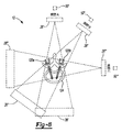
[0067]図2を引き続き参照し、更に図8および図9を参照すると、線源26および検出器28を含む撮像デバイス12を、椎骨124を含む患者14に対して移動させることができる。第2の画像データのために選択された画像を獲得するために、撮像デバイス12を移動させてもよい。第2の画像データは、最小限の数または選択された数の投影を用いて第2の画像データを獲得するのに、撮像デバイス12の最適なまたは処置的に最適な位置であってもよい。選択された数は、選択され計画された処置を確認するのに適切または適正な数であってもよい。選択され計画された処置は、椎弓根スクリュー120を埋め込む選択された位置であってもよい。
With continued reference to FIG. 2 and with further reference to FIGS. 8 and 9,
[0068]図8は、様々な場所28’、28’’、および28’’にある検出器に対して、様々な場所26’、26’’、および26’’’にある線源26を概略的に示している。更に、撮像デバイス追跡デバイス50が、様々な場所50’、50’’、および50’’’で示されている。追跡デバイスの場所50’、50’’、50’’’は、椎骨124に対する視野を生成するため、様々な場所26’、26’’、および26’’’の線源および/または様々な場所28’、28’’、および28’’の検出器の場所を追跡し判定するのに使用することができる。線源26は、当該分野で一般に理解されるように、検出器28において画像データを作成するのに、患者14を通るX線を放射することができる。投影はそれぞれ、それぞれ図8に示される線源26’、26’’、および26’’’の位置に対して、図9に視野A、視野B、および視野Cとして示されるような視野を作成することができる。
[0068] FIG. 8 shows the
[0069]上述したように、ブロック165で、ナビゲーションシステム10を使用して、患者14に対する線源26の位置を自動的に判定して、位置付けられた全ての移植片およびそれらの互いに対する相対位置の画像データを獲得する視野を獲得することができる。したがって、ブロック176で、撮像システム12の選択された数の位置における第2の画像データの獲得が行われる。視野は、ブロック165で判定される位置を指すか、またはそれらの位置にあってもよい。視野は、被験体14に対する移植片の位置を例示または判定するため、1つまたは複数の視野または投影を獲得することを含むことができる。したがって、第2の画像データは、撮像デバイス12の複数の位置からの複数の視野を含んでもよい。例えば、第2の画像データに対して被験体14の2つ以上の視野が獲得されてもよい。
[0069] As noted above, at
[0070]図2を引き続き参照し、また図8および図9を参照すると、視野Aでは、線源26’は画像追跡デバイス50’を用いて追跡することができ、椎骨124を通して検出器28’にX線を投影することができる。獲得された画像データは、表示または保存することができ、第1の椎弓根スクリュー120aおよび第2の椎弓根スクリュー120bの画像データを例示するかまたは含む視野180を含むことができる。具体的には、視野Aの画像は、第1の椎弓根スクリューの画像120a’および第2のスクリューの画像120b’を含むことができる。これらのスクリュー120a、120bは両方とも視野A 180で見ることができるので、スクリューの幾何学形状および位置の判定は視野Aから収集されてもよい。
[0070] With continued reference to FIG. 2 and with reference to FIGS. 8 and 9, in view A, the source 26 'can be tracked using the image tracking device 50' and the detector 28 'through the
[0071]それに加えて、撮像デバイス12は、追跡デバイス50’’を追跡することによって、線源間位置26’’を移動するように操作することができる。例えば、ナビゲーション処理装置60を使用して、撮像デバイス12の位置付けおよび/または撮像デバイス12の直接制御のための座標を提供することができる。それにもかかわらず、次に、椎骨124を通してX線の投影を行うことができ、2つのスクリュー120a、120bは位置28’’において検出器で撮像されてもよい。視野B 184も、120a’’および120b’’で撮像されるような、視野A 180とは異なる観点における2つのスクリュー120a、120bの画像データを含むことができる。2つの視野180、184を使用して、椎骨画像124’および124’’として画像データにやはり含まれる、椎骨124に対する2つのスクリュー120a、120bの位置の計算を作成することができる。上述したように、検出器28および/または線源26の移動は、回転移動を超えるものを含んでもよく、被験体14の長軸に沿った、またはそれを横断する線形移動も含んでもよいことが理解される。
[0071] In addition, the
[0072]図9に示されるように、画像180、184は、埋め込まれた椎弓根スクリュー120a、120b両方の画像データを含み、それらを様々な観点で示す。したがって、ナビゲーション処理装置60または他の適切な処理装置を用いて、適切なアルゴリズムを実行して、椎骨124を含む解剖学的構造に対するスクリューの位置が判定されてもよい。それに加えて、スクリュー120a、120bの幾何学的構成およびサイズを、ナビゲーションメモリ62に保存し、椎骨124内におけるスクリュー120a、120bの位置の判定を支援するために呼び出すことができる。
[0072] As shown in FIG. 9, the
[0073]第2の画像データにおける移植片の位置の判定が、ブロック182で行われる。判定は、画像処理装置58またはナビゲーション処理装置60など、1つまたは複数の処理装置を用いて行われてもよい。選択された処理装置は、ブロック182で、選択された命令を実行して、第2の画像データ内における部材の位置を判定してもよい。
[0073] Determination of the position of the implant in the second image data is performed at
[0074]第2の画像データにおける椎弓根スクリュー120などの移植片の判定または特定は、様々な処理ステップを含んでもよい。例えば、ユーザは、1つもしくは複数の視野または投影におけるシード点を特定してもよい。更に、椎弓根スクリューは、選択されたピクセルもしくはボクセルのコントラストまたは輝度を含んでもよい。いずれの状況でも、様々な領域成長技術を使用して、椎弓根スクリュー120を画像から分割してもよい。したがって、プロセスは、画像データを選択されたシード点から分割することを含んでもよい。
[0074] Determining or identifying an implant, such as
[0075]シード点はまた、分かっているまたは呼び出された判定済みの埋込み位置に基づいて、判定(即ち、プロセッサを用いて命令を実行することによって自動的に判定)または選択されてもよい。上述したように、椎弓根スクリュー120は埋め込まれる際に追跡されてもよく、埋め込まれた位置が保存されてもよい。保存された位置は、ブロック164またはブロック165で、ナビゲーションプロセッサなどのプロセッサによって呼び出されてもよい。したがって、呼び出された位置はまた、第2の画像データで獲得された画像データまたは第2の画像データの一部分(単一の視野など)から分割するため、椎弓根スクリュー120の場所を判定するのに使用されてもよい。椎弓根スクリュー120の呼び出された位置は、椎弓根スクリュー120の中心における点など、選択された点を判定するのに使用されてもよい。様々な実施形態では、保存された位置を呼び出すプロセッサは、保存された位置を使用して、画像データにおけるシード点を判定してもよい。椎弓根スクリュー120の幾何学形状も、メモリ62に保存され、呼び出されてもよい。したがって、画像データにおけるスクリューの位置の分割および判定は、椎弓根スクリュー120の保存された幾何学形状の分かっている中心にある点で始まってもよい。
[0075] The seed point may also be determined (ie automatically determined by executing an instruction using a processor) or selected based on a known or recalled determined embedded position. As mentioned above, the
[0076]第2の画像データに基づいた、スクリュー120a、120bを含む移植片の位置の例示を、ブロック188で実施することができる。スクリュー120の位置は、ブロック106からの第1の画像データ、ブロック112からの画像データに基づいたモデル、またはブロック176からの第2の画像データ上に例示されてもよい。第1の画像データブロック106におけるスクリュー120の位置、またはブロック112からの処理済みモデルは、ブロック182で、スクリュー120の判定された位置に基づいてもよい。更に、第1の画像データブロック106またはモデル形成ブロック112上に重ね合わされるかもしくはそれに相対する、例示のための部材120の判定された位置は、第2の画像データにおけるブロック182でのスクリューの位置の判定のみに基づいてもよい。
[0076] An illustration of the position of the
[0077]様々な実施形態では、スクリューが、ブロック106で獲得された第1の画像データ上、または第1の画像データを用いて生成されたモデル上に例示される場合、ブロック176で獲得される第2の画像データは、ブロック179で、第1の画像データまたはモデルに最初に位置合わせされてもよい。第1の画像データを第2の画像データに位置合わせする際、2つの画像データのうち一方の点が、他方の画像の点に相関またはマッピングされる。第2の画像データは、二次元(2D)から三次元(3D)の位置合わせ技術に関して当該分野で知られているものなどの様々な技術を使用して、第1の画像データに位置合わせされてもよい。様々な実施形態では、第1の画像データおよび第2の画像データの両方に存在してもよい、骨性の特徴または構造は、第1および第2の画像データの両方において(例えば、手動もしくは自動で)特定され、抽出されてもよい。抽出された特徴または構造は、位置合わせおよびマッピングのために整合され使用されてもよい。それに加えて、または別の方法として、第2の画像データは、ブロック164からの撮像デバイスの呼び出された位置に基づいて、第1の画像データに対して位置合わせされてもよい。したがって、第2の画像データの位置は、第1の画像データの位置に対して分かっていてもよく、位置合わせが行われてもよい。
[0077] In various embodiments, if a screw is exemplified on the first image data acquired at
[0078]椎弓根スクリュー120の位置は、上述したように、第2の画像データにおいて判定されてもよい。位置合わせを通して、次に、椎弓根スクリューの位置が、第1の画像データでマッピングまたは判定されてもよい。したがって、この位置合わせによって、第2の画像データからの椎弓根スクリュー120の判定された位置を、第1の画像データおよび/または第1の画像データに基づくモデルに配置もしくは例示することが可能になる。
[0078] The position of the
[0079]スクリューを表すアイコンとして濫用されることがあるスクリュー120a、120bの判定された位置を、判定された位置で、ブロック106で獲得された第1の画像データに基づいて、プロセス画像データブロック112などで生成されてもよいモデル上に重ね合わせることができる。ブロック176から獲得された第2の画像データは、新しいモデルを作成するのに必ずしも使用されなくてもよく、またはユーザ54によって直接見えなくてもよいが、ユーザ54が見るためのアイコン120q(図10)などを有する視野を、ブロック106から獲得された第1の画像データを用いて作成されたモデル上に生成するのに、撮像処理装置58またはナビゲーション処理装置60によって使用されてもよい。上記に基づいて、ユーザ54は、計画を生成するのにも使用されてもよい、獲得された第1の画像データに対する移植片120a、120bの埋め込まれた位置を見ることができる。
[0079] Based on the first image data acquired at
[0080]換言すれば、椎弓根スクリュー120の判定された位置(ここでも、任意の部材が撮像されてよいことが当業者には理解される)は、ブロック176、302で獲得された第2の画像データに基づいて作られてもよい。様々な実施形態によれば、椎弓根スクリュー120の位置は、第2の画像データのみに実質的に基づいて、またはそれのみに基づいて判定されてもよい。次に、判定された位置は、第1の画像データおよび/または第1の画像データに基づいたモデルに対して表示されてもよい。モデルは、患者14の選択された領域の3Dモデルを含んでもよい。第1の画像データに基づく3Dモデルは、複数の2Dスライスまたは投影または他の適切な第1の画像データからの3Dレンダリングを含んでもよい。それにもかかわらず、第1の画像データに対する第2の画像データの位置合わせによって、椎弓根スクリュー120の表現を第1の画像データまたはモデル上に表示することが可能になってもよい。第2の画像データは処置に追随するので、第2の画像データにおける椎弓根スクリュー120の判定された位置は、椎弓根スクリュー120が第1の画像データ上に例示されるときの処置の確認として使用されてもよい。
[0080] In other words, the determined position of the pedicle screw 120 (again, it will be understood by one of ordinary skill in the art that any member may be imaged) was acquired at
[0081]図10を参照すると、ブロック106から獲得された第1の画像データを使用して、椎骨124の画像124’を生成することができる。計画アイコン120pは、画像124’に対して例示することができる。計画アイコンは、ブロック106から獲得された第1の画像データに基づいて、1つまたは複数の移植片の計画または選択された位置を含んでもよい。計画アイコン120pは、選択された移植片の正確な2Dもしくは3Dモデルであってもよく、または単に選択された移植片の幾何学的表現であってもよい。第2の画像データがブロック176で獲得された後、計画アイコン120pに加えてまたはその代わりに、確認アイコン120qが画像124’に対して例示されてもよい。上述したように、第2の画像データが第1の画像データに対して位置合わせされて、椎弓根スクリュー120の判定された位置が画像124’上に重ね合わされて例示されるのを可能にしてもよい。
[0081] Referring to FIG. 10, the first image data obtained from
[0082]したがって、ユーザ54は、少なくとも部分的にまたは全体的に、ブロック176で獲得された第2の画像データによって判定された位置で、確認アイコン124qを見ることができる。換言すれば、第2の画像データにおける椎弓根スクリュー120の位置は、第2の画像データの解析に基づいて(例えば、第2の画像データからの椎弓根スクリューの分割に基づいて)もよい。次に、第1の画像データに対する第2の画像データの位置を使用して、第1の画像データ上における椎弓根スクリューの判定された位置が例示されてもよい。上述したように、確認アイコン120qは、計画アイコン120pに対して画像データ上で重ね合わされ、それによって両方が画像データ124’上で重ね合わされてもよい。したがって、第2の画像データを使用して、処置の初期計画を生成するのに使用できる画像データ124’に対して、確認アイコン120qが例示されてもよい。
Thus, the
[0083]参考までに、図8および図9を参照すると、視野Cは、線源26が線源位置26’’’にあるときに生成されてもよく、トラッカー位置50’’’にあるトラッカー50を用いて追跡されてもよい。視野C位置では、線源26は椎骨124を通して検出器位置28’’’にX線を投射する。2つのスクリューが存在するものの、図9に示される視野C 190は、1つのみのスクリューの視野を含んでもよい。2つのスクリューの一方は他方のスクリューを妨げることがある。したがって、スクリューの少なくとも1つが、視野Cにおいて別のスクリューによって妨げられることがある。したがって、視野Cは、スクリュー120a、120bを含む移植片の位置を判定するのに、適切な情報を提供しないことがある。換言すれば、視野Cは妨げられるかまたは遮られることがある(例えば、椎弓根スクリューの1つなど、少なくとも1つの関心物品が、椎弓根スクリューの別の1つによって少なくとも部分的に遮られるかまたは妨げられる)が、視野Aおよび視野Bは妨げられないかまたは遮られない視野であってもよい。妨げられない視野によって、患者14を通る放射線露出を含む投射をより少なくして、部材の全てまたはほとんどを判定することが可能になる。
[0083] For reference, with reference to FIGS. 8 and 9, the field of view C may be generated when the
[0084]したがって、撮像デバイス追跡デバイス50を用いた撮像デバイス12の追跡は、第2の画像データを獲得するための有効で効率的な位置への撮像デバイスの移動を支援してもよい。ブロック165におけるこの判定は、移植片の位置の判定を行うのに十分な画像データを獲得するのに必要な露出の数を低減してもよい。したがって、方法100による第2の画像データの獲得に要する、椎骨124に対する移植片の位置情報の高度な弁別を含む視野または投影は、最小限の量であってもよい。これにより、視野C 190などのより弁別性が低い視野が、獲得されないかまたは必ずしも獲得されなくてもよく、したがってかかる視野を獲得するときに患者をX線に露出させないことを確保することができる。
Thus, tracking of the
[0085]上述したように、患者トラッカーがまだ患者14に取り付けられているか否かの判定を、ブロック162で行うことができる。患者トラッカーが取り付けられていない場合、「いいえ」のブロック200への経路を辿らなくてもよい。撮像デバイス12は依然として、椎弓根スクリュー120の埋込みなど、患者の処置中に患者14に対して移動されてもよく、撮像デバイス12もやはり、ブロック150で獲得されるように判定される第2の画像データを獲得するのに、患者12に対して移動されてもよい。患者を患者追跡デバイス48が追跡しなくなると、上述したように、患者14の少なくとも1つの試験画像データの投影または視野を獲得して、移植片の位置を判定するのに患者14を通る最小限の数の投影を獲得するための、患者14に対する撮像システム12の適切な位置を判定するのを支援することができる。
[0085] As noted above, a determination may be made at
[0086]「いいえ」のブロック200を通る経路を辿らない場合、ブロック202で、撮像デバイス12を患者14に対して撮像デバイスの第1の試験位置まで移動させることができる。撮像デバイス試験位置は、患者14に対する任意の適切な位置であることができ、ガントリ20の位置付け、ならびに線源26および検出器28の選択された場所の両方を含んでもよい。第1の試験位置で、ブロック204で第1の試験画像データが獲得されてもよい。第1の試験画像データは、第1の試験位置で患者14を通って得られる投影として獲得される画像データであることができる。
[0086] If the path through the "No" block 200 is not followed, at
[0087]ブロック204で第1の試験位置において獲得される画像データは、画像処理装置58またはナビゲーション処理システム60などの適切な処理装置を用いて処理して、獲得された第1の画像データにおける移植片120の位置を判定することができる。第1の試験画像データにおける移植片120の配向および場所の判定によって、ブロック208で、第2の画像データを獲得するための1つまたは複数の位置の判定が可能になる。しかしながら、第1の試験画像データはまた、第2の獲得された画像データの視野または投影として使用されてもよいことが理解される。更に、ブロック208で第2の画像データを獲得するための1つまたは複数の位置の判定は、ブロック204で獲得された第1の試験画像データのみに基づいてもよい。したがって、患者トラッカー48を含む、患者14に対する撮像デバイス12の追跡は、ブロック208において第2の画像データを獲得するための1つまたは複数の位置の判定に必須ではない。
[0087] The image data acquired at the first test position at
[0088]第1の試験画像データは、第2の画像データを獲得する撮像デバイスの位置を判定するのに使用されてもよい。したがって、上述したように、撮像デバイス12を追跡するのではなく、第1の試験画像データを解析して、第2の画像データを獲得するための適切な位置が判定されてもよい。ブロック208で第2の画像データを獲得するための判定された位置で、第1の試験画像データが、その中における、また患者14に対する移植片の位置を判定するために評価されてもよい。しかしながら、第1の試験画像データは、移植片120全ての位置を完全に判定するのに十分な画像データを含まなくてもよい。それにより、ブロック208で判定された位置によって、上述したように、移植片の位置を判定するのに最小限の数の投影を獲得するため、最小限の数の位置で、撮像デバイス12を用いて第2の画像データを獲得することが可能になってもよい。
The first test image data may be used to determine the position of the imaging device to obtain the second image data. Thus, as discussed above, rather than tracking the
[0089]第1の試験画像データの解析は、一般に当該分野で理解されるように、画像データを処理してモデルを生成するのと同様の手法で行うことができ、第1の試験画像データにおける移植片の位置の判定を可能にする。したがって、ブロック208で第2の画像データを獲得するための場所の判定は、患者トラッカー48を用いて患者14を追跡するか、または撮像デバイス追跡デバイス50を用いて撮像デバイス12を追跡することなく、実施することができる。移植片120の場所および配向が第1の試験画像データで判定されると、第2の画像データを獲得する場所の判定はそれに基づくことができる。
[0089] The analysis of the first test image data may be performed in the same manner as processing the image data to generate a model, as generally understood in the art, and the first test image data Allow determination of the position of the graft at Thus, the determination of the location for acquiring the second image data at
[0090]更に、処置情報はまた、自動でもしくはユーザによって入力されるか、またはメモリ62に保存された計画から呼び出されてもよい。例えば、移植片の数、および移植片の選択された相対位置は、ブロック208で位置を判定するのを支援するのに使用されてもよい。例えば、第1の試験画像が2つのみの移植片を含むが、4つの移植片が配置されたことが分かっている場合、プロセッサは、画像における2つの移植片の相対位置を判定して、他の2つの移植片の見込まれる位置を判定してもよい。更に、軸線方向視野が2つのみの移植片を撮像した場合、4つ全ての移植片を撮像するのに、選択された斜めの視野が選択されてもよい。撮像デバイスの位置の判定は、第1の試験画像データの呼び出された情報および解析に基づいて、プロセッサによって自動的に判定されてもよい。更に、移植片の位置は、メモリシステムからプロセッサシステムによって呼び出されてもよい。
Furthermore, the treatment information may also be automatically or input by the user, or be called from a plan stored in the
[0091]ブロック208で第2の画像データを獲得する場所の判定が完了すると、ブロック300で、撮像デバイス12を被験体に対する判定された1つまたは複数の位置に移動させることができる。次に、ブロック176における第2の画像データの獲得と同様の手法で、ブロック302で、第2の画像データを1つまたは複数の位置で獲得することができる。ブロック302で、第2の画像データが判定された1つまたは複数の位置で獲得されると、上述したように、ブロック182で第2の画像データにおいて(例えば、椎弓根スクリューを第2の画像データから分割することによって)椎弓根スクリュー120の位置が判定されてもよい。第2の画像データはまた、やはり上述したように、ブロック179で、第1の画像データに対して位置合わせされてもよい。様々な実施形態では、位置合わせは、特徴または構造の抽出、ならびに第1および第2の画像データの間の位置合わせによって行われてもよい。椎弓根スクリューの判定された位置を、上述したように、ブロック188で、第2の画像データまたは第1の画像データ上に例示することができる。
[0091] Once the determination of where to obtain the second image data at
[0092]第1の画像データ、またはブロック188で第1の画像データを使用して形成されたモデルなど、画像データ上における移植片120の位置を例示した後、方法は、終了ブロック154で終わることができる。上述したように、撮像システム12を使用して、第2の画像データを獲得して、計画された処置の確認のために移植片の位置を例示するのを支援してもよい。更に、第2の画像データに基づいた移植片の例示は、ユーザの専門的技術に基づいて計画を達成するかまたは計画を増補するため、外科ステップなどの追加の処置ステップが実施されるように選択されるか否かを、ユーザ54が判定するのを支援することができる。したがって、第2の画像データは、患者14に対して処置を実施するか、あるいは計画を達成するかまたは選択された結果を達成するのを支援するのに使用される。しかしながら、任意の適切な被験体の第2の画像データを獲得することができ、図1に示されるようなヒトの被験体に限定されないことが理解される。
After illustrating the position of the
[0093]したがって、図2に示される方法によって、完全な画像データセットを獲得することなく、第2の画像データを獲得することが可能になる。当業者には理解されるように、選択された量の画像データ(完全なセットなど)を使用して、患者14の三次元モデルを生成することができる。ブロック106で獲得された第1の画像データは、選択された品質の患者14のモデルを生成するのに十分な画像データであることができる。したがって、第1の画像データの量は、X線ビームが(線源26と検出器28との間で)ガントリ20を介して患者14の周りを移動するにつれて、患者14の少なくとも300個の投影を獲得することを含んでもよい。第2の画像データは、複数の獲得のうち単一の獲得を含んでもよいが、両方とも一般に、第1の画像データ獲得の投影よりも少ない。例えば、試験画像データ獲得は、約1〜約3回の投影を含んでもよい。したがって、第2の画像データ(試験画像データに基づくかもしくは基づかない)は、X線ビームを移動させることなどによって、患者14の周りにおいて斜めの角度で約10個以下の投影を含んでもよい。しかしながら、第2の画像データは、第1の画像データを含む術前画像データなど、前の画像データに対して埋め込まれたハードウェアの位置を位置合わせまたは検証するのに、角度が見えるように最適化されてもよい。したがって、第2の画像データは、第1の画像データに対して最小限に抑えることができ、それでもやはり、上述したように、選択された計画を確認するために画像データを提供するか、または患者14に対する外科処置の完了を支援することが可能である。
Thus, the method shown in FIG. 2 makes it possible to acquire second image data without acquiring a complete image data set. As appreciated by those skilled in the art, selected amounts of image data (such as a complete set) can be used to generate a three-dimensional model of the
[0094](ブロック176もしくは302のどちらかで獲得された)第2の画像データは、椎弓根スクリュー120(または撮像される他の部材)の位置を判定するのに使用される唯一のデータであってもよい。更に、第2の画像データは、ブロック106からの第1の画像データ、またはブロック112でそこから形成されるモデルに対する部材の位置を判定するのに使用される、唯一のデータであってもよい。そのため、第2の画像データは、患者14に対する部材120の位置を確認するのに、追跡情報なしで、またはそれが存在しない状態で使用されてもよい。また、上述したように、ブロック182で判定された部材の位置は、ブロック106からの第1の画像データまたはブロック112からのモデルに対して、例示されるかまたは重ね合わされてもよい。
[0094] The second image data (acquired at either block 176 or 302) is the only data used to determine the position of the pedicle screw 120 (or other member to be imaged) It may be Further, the second image data may be the first image data from
[0095]更に、部材120は、骨性組織などの硬組織内に必ずしも配置されなくてもよい。埋め込まれる部材は、脳深部刺激プローブまたは電極など、軟組織内に配置されてもよい。電極の配置は計画されてもよく、画像データは、処置の選択された部分後に獲得されてもよい。上述したように、部材の位置が第2の画像データで判定されてもよく、部材を表すアイコンが重ね合わされてもよい。更に、第2の画像データを獲得するための撮像デバイスの位置を判定するのに、撮像デバイスが追跡されてもよく、ならびに/または試験画像が獲得されてもよい。そのため、被験体に配置される部材は硬組織または骨性組織に必ずしも配置されなくてもよいことを、当業者であれば理解するであろう。
Furthermore, the
[0096]実施形態の上述の説明を例示および説明の目的で提供した。網羅的であることを意図するものではなく、または本発明を限定しようとするものではない。特定の実施形態の個々の要素または特徴は、一般に、その特定の実施形態に限定されるものではないが、適切な場合は交換可能であり、具体的に図示または記載されない場合であっても、選択された実施形態で使用することができる。同じことが多くの形で変更されてもよい。かかる変更は、本発明からの逸脱と見なされるものではなく、全てのかかる修正は本発明の範囲内に含まれることが意図される。 [0096] The foregoing description of the embodiments has been provided for the purposes of illustration and description. It is not intended to be exhaustive or to limit the invention. The individual elements or features of a particular embodiment are not generally limited to that particular embodiment, but are interchangeable where appropriate, even if not specifically illustrated or described, It can be used in selected embodiments. The same may be changed in many ways. Such variations are not to be regarded as a departure from the invention, and all such modifications are intended to be included within the scope of the invention.
Claims (22)
前記撮像デバイスを関心部分に対する選択された位置に移動させるステップと、
前記関心部分の確認画像データ(confirmation image data)を獲得するステップと、
前記獲得された確認画像データ内における部材(member)の位置を判定するステップと、
前記判定された位置における前記部材を表すアイコンを、以前の獲得画像データを用いて生成された前記関心部分のモデル上に重ね合わせるステップであって、前記以前の獲得画像データが前記確認画像データの前に獲得される、ステップとを含む、方法。 A method of identifying at least a portion of a procedure using image data acquired by an imaging device, the method comprising:
Moving the imaging device to a selected position relative to a portion of interest;
Acquiring confirmation image data of the portion of interest;
Determining the position of a member within the acquired confirmation image data;
Overlaying an icon representing the member at the determined position on a model of the portion of interest generated using previously acquired image data, wherein the previously acquired image data is the confirmation image data A method, which is obtained before, including the steps.
前記関心部分に対する前記撮像デバイスの位置を追跡するステップとを更に含む、請求項1に記載の方法。 Tracking the position of the member relative to the portion of interest;
Tracking the position of the imaging device relative to the portion of interest.
前記関心部分および前記部材の確認画像データを獲得するために、前記撮像デバイスの検出器を前記関心部分に対する第1の位置に移動させながら、前記検出器を追跡するステップと、
前記関心部分および前記部材の確認画像データを獲得するために、前記撮像デバイスの前記検出器を前記関心部分に対する第2の位置に移動させながら、前記検出器を追跡するステップとを含む、請求項2に記載の方法。 Tracking the position of the imaging device relative to the portion of interest
Tracking the detector while moving the detector of the imaging device to a first position relative to the portion of interest to obtain verification image data of the portion of interest and the member;
Tracking the detector while moving the detector of the imaging device to a second position relative to the portion of interest to obtain confirmation image data of the portion of interest and the member. The method described in 2.
前記以前の獲得画像データを獲得した際の時間の少なくとも一部分の間の前記撮像デバイスの保存された位置をメモリシステムから呼び出すステップと、
前記獲得された確認画像データ内における前記部材の前記位置の判定を可能にするために、第1の投影(projection)において前記部材の妨げられない画像データを獲得する、前記検出器の位置を判定するステップと、
前記判定された位置に移動するように前記検出器に命令するステップとを含み、
前記以前の獲得画像データおよび前記確認画像データが両方とも複数の投影を含むことができ、前記複数の投影がそれぞれ前記検出器の異なる位置におけるものである、請求項3に記載の方法。 Tracking the detector comprises
Recalling from the memory system the stored position of the imaging device during at least a portion of the time at which the previously acquired image data was acquired;
Determining the position of the detector that acquires unobstructed image data of the member in a first projection to enable determination of the position of the member in the acquired confirmation image data Step to
Instructing the detector to move to the determined position;
The method according to claim 3, wherein the previously acquired image data and the verification image data can both comprise a plurality of projections, wherein the plurality of projections are respectively at different positions of the detector.
前記処理装置によって、前記判定された位置にある前記部材を表す前記アイコンを、前記関心部分の前記モデル上に重ね合わせるために、前記部材の前記位置をモデル化する命令を実行するステップとを更に含む、請求項1から4のいずれか一項に記載の方法。 Executing instructions to generate the model of the portion of interest generated by the processing device using the previously acquired image data;
Executing an instruction to model the position of the member to overlay the icon representing the member at the determined position on the model of the portion of interest by the processor. The method according to any one of claims 1 to 4, comprising.
前記獲得された試験画像データから部材を抽出することによって、前記獲得された試験画像を評価するステップと、
前記獲得された試験画像の前記評価のみに基づいて、前記関心部分内における前記部材の位置を判定するステップと、
異なる移植片(implants)同士または異なる解剖学的特徴(anatomical features)同士のうち少なくとも一方の重なりを少なくとも最小限に抑えるように、前記関心部分の前記確認画像データを獲得するための少なくとも1つの位置を判定する命令を、処理装置によって、前記部材の前記判定された位置に基づいて実行するステップとを更に含む、請求項1から5のいずれか一項に記載の方法。 Acquiring a test image of at least a first portion of the portion of interest including the member;
Evaluating the acquired test image by extracting components from the acquired test image data;
Determining the position of the component within the portion of interest based solely on the evaluation of the acquired test image;
At least one position for acquiring said confirmation image data of said portion of interest, so as to at least minimize the overlap of different implants and / or different anatomical features. 6. The method according to any one of claims 1 to 5, further comprising the step of: performing an instruction of determining by the processing device based on the determined position of the member.
被験体の関心部分に対する選択された位置に移動され、前記被験体の前記関心部分の確認画像データを獲得するように構成された撮像デバイスと、
プロセッサシステムであって、
前記撮像デバイスを用いて獲得される、前記被験体の前記関心部分の前記獲得された確認画像データを評価し、
前記被験体の前記関心部分の前記獲得された確認画像データに基づいて、部材の位置を判定する
命令を実行するように構成されたプロセッサシステムと、
以前の獲得画像データを用いて生成された前記関心部分の前記画像上の前記判定された位置で、画像上に重ね合わされた前記部材を表すアイコンを表示するように構成された表示デバイスであって、前記以前の獲得画像データが前記確認画像データの前に獲得される、表示デバイスとを備える、システム。 A system for identifying at least a portion of a treatment using image data, the system comprising:
An imaging device moved to a selected position relative to a portion of interest of a subject and configured to obtain confirmation image data of the portion of interest of the subject;
A processor system,
Evaluating the acquired confirmation image data of the portion of interest of the subject acquired using the imaging device;
A processor system configured to execute an instruction to determine a position of a component based on the acquired confirmation image data of the portion of interest of the subject.
A display device configured to display an icon representing the member superimposed on an image at the determined position on the image of the portion of interest generated using previously acquired image data, A display device, wherein the previously acquired image data is acquired before the confirmation image data.
前記以前の画像データを獲得する間の、前記撮像システムおよび前記関心部分の前記保存された相対位置を呼び出し、
前記撮像システムの前記呼び出された保存相対位置、前記以前の画像データを獲得する間の前記関心部分、または前記部材の追跡された位置の少なくとも1つに基づいて、妨げられない画像データである前記部材の前記確認画像データを獲得するための前記撮像デバイスの少なくとも1つの位置を判定する
命令を実行するように更に構成された、請求項14に記載のシステム。 The processor system
Recalling the stored relative position of the imaging system and the portion of interest while acquiring the previous image data;
Unobstructed image data based on at least one of the recalled stored relative position of the imaging system, the portion of interest during acquisition of the previous image data, or the tracked position of the member The system according to claim 14, further configured to execute an instruction to determine a position of at least one of the imaging device to obtain the confirmation image data of a member.
第1の試験画像データを評価して前記部材を特定し、
前記撮像デバイスを用いて獲得される前記関心部分の前記画像データを獲得するための前記撮像デバイスの少なくとも1つの位置を判定する
命令を実行するように更に構成される、請求項11から15のいずれか一項に記載のシステム。 The processing system
Evaluating the first test image data to identify the member;
16. The method according to any of claims 11-15, further comprising: executing an instruction to determine at least one position of the imaging device for acquiring the image data of the portion of interest acquired using the imaging device. The system according to one or more items.
前記撮像デバイスを用いて、被験体に対する第1の位置で、前記被験体の少なくとも関心部分の第1の画像データを獲得するステップと、
前記撮像デバイスを前記第1の位置から移動させるステップと、
処置後の第2の画像データを獲得するために、前記被験体の少なくとも前記関心部分に対する前記撮像デバイスの第2の位置を判定するように、第1の処理装置を操作するステップと、
前記撮像デバイスを前記関心部分に対する前記第2の位置に移動させるステップと、
前記撮像デバイスを用いて、前記第2の位置で、前記関心部分の前記第2の画像データを獲得するステップと、
第2の処理装置を操作して、
(i)前記獲得された第2の画像データ内における部材の位置を判定し、
(ii)前記獲得された第2の画像データ内における前記部材の前記判定された位置に基づいて、前記部材の第1の画像データ位置を判定する、ステップと、
前記判定された第1の画像データ位置における前記部材を表す、前記第1の画像データ上に重ね合わされたアイコンの表示を見るステップとを含む、方法。 A method of identifying at least a portion of a treatment using image data acquired by an imaging device, the method comprising:
Acquiring first image data of at least a portion of interest of the subject at a first position relative to the subject using the imaging device;
Moving the imaging device from the first position;
Operating a first processing device to determine a second position of the imaging device relative to at least the portion of interest of the subject to obtain second image data after treatment;
Moving the imaging device to the second position with respect to the portion of interest;
Acquiring the second image data of the portion of interest at the second position using the imaging device;
Operating the second processor
(I) determining the position of the member within the acquired second image data;
(Ii) determining a first image data position of the member based on the determined position of the member in the acquired second image data;
Viewing a display of an icon superimposed on the first image data representing the member at the determined first image data position.
前記第1の位置の前記保存された座標を呼び出すステップとを更に含み、
前記第2の画像データを獲得するために、前記被験体の少なくとも前記関心部分に対する前記撮像デバイスの前記第2の位置を判定するように、前記第1の処理装置を操作するステップが、前記呼び出された保存座標に少なくとも基づく、請求項18または19に記載の方法。 Storing coordinates of the first position of the imaging device;
And calling the stored coordinates of the first position.
Operating the first processing device to determine the second position of the imaging device relative to at least the portion of interest of the subject to obtain the second image data; A method according to claim 18 or 19, based at least on stored coordinates.
前記被験体に対する前記第1の試験画像データ内における前記部材の位置を判定するように、前記第1の処理装置を操作するステップとを更に含み、
前記第2の画像データを獲得するために、前記被験体の少なくとも前記関心部分に対する前記撮像デバイスの前記第2の位置を判定するように、前記第1の処理装置を操作するステップが、前記部材の前記判定された位置に少なくとも基づく、請求項18から20のいずれか一項に記載の方法。 Acquiring a first test image comprising the member;
Operating the first processing device to determine the position of the member within the first test image data relative to the subject.
Operating the first processing device to determine the second position of the imaging device relative to at least the portion of interest of the subject to obtain the second image data; 21. A method according to any one of claims 18 to 20, based at least on the determined position of.
Applications Claiming Priority (3)
| Application Number | Priority Date | Filing Date | Title |
|---|---|---|---|
| US15/141,331 | 2016-04-28 | ||
| US15/141,331 US10191615B2 (en) | 2016-04-28 | 2016-04-28 | Method and apparatus for image-based navigation |
| PCT/US2017/029906 WO2017189881A1 (en) | 2016-04-28 | 2017-04-27 | Method and apparatus for image-based navigation field |
Publications (2)
| Publication Number | Publication Date |
|---|---|
| JP2019514547A true JP2019514547A (en) | 2019-06-06 |
| JP2019514547A5 JP2019514547A5 (en) | 2020-06-11 |
Family
ID=58692640
Family Applications (1)
| Application Number | Title | Priority Date | Filing Date |
|---|---|---|---|
| JP2018556475A Pending JP2019514547A (en) | 2016-04-28 | 2017-04-27 | Image-based navigation method and apparatus |
Country Status (8)
| Country | Link |
|---|---|
| US (4) | US10191615B2 (en) |
| EP (2) | EP3448296B1 (en) |
| JP (1) | JP2019514547A (en) |
| KR (1) | KR20190005177A (en) |
| CN (1) | CN109414295B (en) |
| AU (1) | AU2017258292B2 (en) |
| CA (1) | CA3022422A1 (en) |
| WO (1) | WO2017189881A1 (en) |
Families Citing this family (150)
| Publication number | Priority date | Publication date | Assignee | Title |
|---|---|---|---|---|
| CA2625826C (en) | 2005-10-19 | 2014-08-05 | Pulsar Vascular, Inc. | Methods and systems for endovascularly clipping and repairing lumen and tissue defects |
| US9402707B2 (en) | 2008-07-22 | 2016-08-02 | Neuravi Limited | Clot capture systems and associated methods |
| CN102202585B (en) | 2008-09-05 | 2014-04-02 | 帕尔萨脉管公司 | Systems and methods for supporting or occluding a physiological opening or cavity |
| EP2629684B1 (en) | 2010-10-22 | 2018-07-25 | Neuravi Limited | Clot engagement and removal system |
| WO2014139845A1 (en) | 2013-03-14 | 2014-09-18 | Neuravi Limited | A clot retrieval device for removing occlusive clot from a blood vessel |
| WO2012120490A2 (en) | 2011-03-09 | 2012-09-13 | Neuravi Limited | A clot retrieval device for removing occlusive clot from a blood vessel |
| US11259824B2 (en) | 2011-03-09 | 2022-03-01 | Neuravi Limited | Clot retrieval device for removing occlusive clot from a blood vessel |
| KR102018035B1 (en) | 2011-06-03 | 2019-09-05 | 펄사 배스큘라, 아이엔씨. | Aneurysm devices with additional anchoring mechanisms and associated systems and methods |
| WO2013052920A1 (en) | 2011-10-05 | 2013-04-11 | Pulsar Vascular, Inc. | Devices, systems and methods for enclosing an anatomical opening |
| US10603157B2 (en) | 2013-03-13 | 2020-03-31 | DePuy Synthes Products, Inc. | Braid implant delivery and retraction device with distal engagement |
| US10561509B2 (en) | 2013-03-13 | 2020-02-18 | DePuy Synthes Products, Inc. | Braided stent with expansion ring and method of delivery |
| US9433429B2 (en) | 2013-03-14 | 2016-09-06 | Neuravi Limited | Clot retrieval devices |
| ES2713633T3 (en) | 2013-03-14 | 2019-05-23 | Neuravi Ltd | Devices and methods for elimination of severe blockages of blood vessels |
| US10285720B2 (en) | 2014-03-11 | 2019-05-14 | Neuravi Limited | Clot retrieval system for removing occlusive clot from a blood vessel |
| US11154302B2 (en) | 2014-03-31 | 2021-10-26 | DePuy Synthes Products, Inc. | Aneurysm occlusion device |
| US11076860B2 (en) | 2014-03-31 | 2021-08-03 | DePuy Synthes Products, Inc. | Aneurysm occlusion device |
| US10441301B2 (en) | 2014-06-13 | 2019-10-15 | Neuravi Limited | Devices and methods for removal of acute blockages from blood vessels |
| US10265086B2 (en) | 2014-06-30 | 2019-04-23 | Neuravi Limited | System for removing a clot from a blood vessel |
| US9918718B2 (en) | 2014-08-08 | 2018-03-20 | DePuy Synthes Products, Inc. | Embolic coil delivery system with retractable mechanical release mechanism |
| US10206796B2 (en) | 2014-08-27 | 2019-02-19 | DePuy Synthes Products, Inc. | Multi-strand implant with enhanced radiopacity |
| US9782178B2 (en) | 2014-09-19 | 2017-10-10 | DePuy Synthes Products, Inc. | Vasculature occlusion device detachment system with tapered corewire and heater activated fiber detachment |
| US10363054B2 (en) | 2014-11-26 | 2019-07-30 | Neuravi Limited | Clot retrieval device for removing occlusive clot from a blood vessel |
| US11253278B2 (en) | 2014-11-26 | 2022-02-22 | Neuravi Limited | Clot retrieval system for removing occlusive clot from a blood vessel |
| US10617435B2 (en) | 2014-11-26 | 2020-04-14 | Neuravi Limited | Clot retrieval device for removing clot from a blood vessel |
| US10013808B2 (en) | 2015-02-03 | 2018-07-03 | Globus Medical, Inc. | Surgeon head-mounted display apparatuses |
| US10191615B2 (en) | 2016-04-28 | 2019-01-29 | Medtronic Navigation, Inc. | Method and apparatus for image-based navigation |
| US10285710B2 (en) | 2016-06-01 | 2019-05-14 | DePuy Synthes Products, Inc. | Endovascular detachment system with flexible distal end and heater activated detachment |
| EP3782562A1 (en) | 2016-08-17 | 2021-02-24 | Neuravi Limited | A clot retrieval system for removing occlusive clot from a blood vessel |
| US10076428B2 (en) | 2016-08-25 | 2018-09-18 | DePuy Synthes Products, Inc. | Expansion ring for a braided stent |
| JP7046924B2 (en) | 2016-09-06 | 2022-04-04 | ニューラヴィ・リミテッド | Clot recovery device for removing obstructive clots from blood vessels |
| US10292851B2 (en) | 2016-09-30 | 2019-05-21 | DePuy Synthes Products, Inc. | Self-expanding device delivery apparatus with dual function bump |
| JP7170631B2 (en) | 2016-10-05 | 2022-11-14 | ニューヴェイジヴ,インコーポレイテッド | Surgical navigation system and related methods |
| US10517708B2 (en) | 2016-10-26 | 2019-12-31 | DePuy Synthes Products, Inc. | Multi-basket clot capturing device |
| US10905853B2 (en) | 2017-01-17 | 2021-02-02 | DePuy Synthes Products, Inc. | System and method for delivering a catheter |
| US10881497B2 (en) | 2017-01-26 | 2021-01-05 | DePuy Synthes Products, Inc. | Composite vascular flow diverter |
| CN110545739A (en) | 2017-02-23 | 2019-12-06 | 德普伊新特斯产品公司 | aneurysm devices and delivery systems |
| US20180247712A1 (en) | 2017-02-24 | 2018-08-30 | Masimo Corporation | System for displaying medical monitoring data |
| WO2018156809A1 (en) * | 2017-02-24 | 2018-08-30 | Masimo Corporation | Augmented reality system for displaying patient data |
| JP7159208B2 (en) | 2017-05-08 | 2022-10-24 | マシモ・コーポレイション | A system for pairing a medical system with a network controller by using a dongle |
| US11033341B2 (en) | 2017-05-10 | 2021-06-15 | Mako Surgical Corp. | Robotic spine surgery system and methods |
| EP4344658A2 (en) | 2017-05-10 | 2024-04-03 | MAKO Surgical Corp. | Robotic spine surgery system |
| EP3445048A1 (en) | 2017-08-15 | 2019-02-20 | Holo Surgical Inc. | A graphical user interface for a surgical navigation system for providing an augmented reality image during operation |
| US10806462B2 (en) | 2017-12-21 | 2020-10-20 | DePuy Synthes Products, Inc. | Implantable medical device detachment system with split tube and cylindrical coupling |
| US10751065B2 (en) | 2017-12-22 | 2020-08-25 | DePuy Synthes Products, Inc. | Aneurysm device and delivery system |
| US10905430B2 (en) | 2018-01-24 | 2021-02-02 | DePuy Synthes Products, Inc. | Aneurysm device and delivery system |
| US20190254753A1 (en) | 2018-02-19 | 2019-08-22 | Globus Medical, Inc. | Augmented reality navigation systems for use with robotic surgical systems and methods of their use |
| US10918390B2 (en) | 2018-03-30 | 2021-02-16 | DePuy Synthes Products, Inc. | Helical balloon assist device and method for using the same |
| US10786259B2 (en) | 2018-03-30 | 2020-09-29 | DePuy Synthes Products, Inc. | Split balloon assist device and method for using the same |
| CN112040875A (en) | 2018-04-06 | 2020-12-04 | 美敦力公司 | Image-based navigation system and method of using the same |
| US10806461B2 (en) | 2018-04-27 | 2020-10-20 | DePuy Synthes Products, Inc. | Implantable medical device detachment system with split tube |
| US11596412B2 (en) | 2018-05-25 | 2023-03-07 | DePuy Synthes Products, Inc. | Aneurysm device and delivery system |
| US11058430B2 (en) | 2018-05-25 | 2021-07-13 | DePuy Synthes Products, Inc. | Aneurysm device and delivery system |
| US10939915B2 (en) | 2018-05-31 | 2021-03-09 | DePuy Synthes Products, Inc. | Aneurysm device and delivery system |
| US10667833B2 (en) | 2018-06-08 | 2020-06-02 | Neuravi Limited | Guidewire with an atraumatic clot-circumventing configured distal end for use in an endovascular medical system |
| US10898216B2 (en) | 2018-06-13 | 2021-01-26 | DePuy Synthes Products, Inc. | Vasculature obstruction capture device |
| AU2019204522A1 (en) | 2018-07-30 | 2020-02-13 | DePuy Synthes Products, Inc. | Systems and methods of manufacturing and using an expansion ring |
| US10905431B2 (en) | 2018-08-03 | 2021-02-02 | DePuy Synthes Products, Inc. | Spiral delivery system for embolic braid |
| US10456280B1 (en) | 2018-08-06 | 2019-10-29 | DePuy Synthes Products, Inc. | Systems and methods of using a braided implant |
| US10278848B1 (en) | 2018-08-06 | 2019-05-07 | DePuy Synthes Products, Inc. | Stent delivery with expansion assisting delivery wire |
| US11051825B2 (en) | 2018-08-08 | 2021-07-06 | DePuy Synthes Products, Inc. | Delivery system for embolic braid |
| US10813780B2 (en) | 2018-08-08 | 2020-10-27 | DePuy Synthes Products, Inc. | Intraluminal implant delivery system and method |
| US10842498B2 (en) | 2018-09-13 | 2020-11-24 | Neuravi Limited | Systems and methods of restoring perfusion to a vessel |
| JP2020044335A (en) | 2018-09-20 | 2020-03-26 | デピュイ・シンセス・プロダクツ・インコーポレイテッド | Stent with shaped wire |
| US11123077B2 (en) | 2018-09-25 | 2021-09-21 | DePuy Synthes Products, Inc. | Intrasaccular device positioning and deployment system |
| US11406416B2 (en) | 2018-10-02 | 2022-08-09 | Neuravi Limited | Joint assembly for vasculature obstruction capture device |
| US11253287B2 (en) | 2018-10-04 | 2022-02-22 | Neuravi Limited | Retrograde blood flow occlusion flushing device |
| US11076861B2 (en) | 2018-10-12 | 2021-08-03 | DePuy Synthes Products, Inc. | Folded aneurysm treatment device and delivery method |
| AU2019374890A1 (en) * | 2018-11-08 | 2021-06-03 | Mako Surgical Corp. | Robotic spine surgery system and methods |
| US11406392B2 (en) | 2018-12-12 | 2022-08-09 | DePuy Synthes Products, Inc. | Aneurysm occluding device for use with coagulating agents |
| US11147562B2 (en) | 2018-12-12 | 2021-10-19 | DePuy Synthes Products, Inc. | Systems and methods for embolic implant detachment |
| US11272939B2 (en) | 2018-12-18 | 2022-03-15 | DePuy Synthes Products, Inc. | Intrasaccular flow diverter for treating cerebral aneurysms |
| US11039944B2 (en) | 2018-12-27 | 2021-06-22 | DePuy Synthes Products, Inc. | Braided stent system with one or more expansion rings |
| US11134953B2 (en) | 2019-02-06 | 2021-10-05 | DePuy Synthes Products, Inc. | Adhesive cover occluding device for aneurysm treatment |
| US11273285B2 (en) | 2019-02-07 | 2022-03-15 | DePuy Synthes Products, Inc. | Ancillary device for detaching implants |
| FR3092748A1 (en) * | 2019-02-18 | 2020-08-21 | Sylorus Robotics | Image processing methods and systems |
| ES2910600T3 (en) | 2019-03-04 | 2022-05-12 | Neuravi Ltd | Powered Clot Recovery Catheter |
| US20220133409A1 (en) * | 2019-03-04 | 2022-05-05 | Hangzhou Santan Medical Technology Co., Ltd | Method for Determining Target Spot Path |
| US11382633B2 (en) | 2019-03-06 | 2022-07-12 | DePuy Synthes Products, Inc. | Strut flow diverter for cerebral aneurysms and methods for preventing strut entanglement |
| US20200297425A1 (en) * | 2019-03-18 | 2020-09-24 | Medtronic Navigation, Inc. | System and Method for Imaging |
| US20200297424A1 (en) | 2019-03-18 | 2020-09-24 | Medtronic Navigation, Inc. | System and Method for Imaging |
| US11337706B2 (en) | 2019-03-27 | 2022-05-24 | DePuy Synthes Products, Inc. | Aneurysm treatment device |
| US11185334B2 (en) | 2019-03-28 | 2021-11-30 | DePuy Synthes Products, Inc. | Single lumen reduced profile occlusion balloon catheter |
| US11051928B2 (en) | 2019-04-11 | 2021-07-06 | Neuravi Limited | Floating carotid filter |
| US10758194B1 (en) | 2019-04-17 | 2020-09-01 | Medtronic Navigation, Inc. | Filter system and method for imaging a subject |
| US11931522B2 (en) | 2019-05-09 | 2024-03-19 | Neuravi Limited | Inflation lumen kink protection and balloon profile |
| US11607531B2 (en) | 2019-05-09 | 2023-03-21 | Neuravi Limited | Balloon catheter with venting of residual air in a proximal direction |
| US11571553B2 (en) | 2019-05-09 | 2023-02-07 | Neuravi Limited | Balloon guide catheter with thermally expandable material |
| USD959659S1 (en) | 2019-05-10 | 2022-08-02 | DePuy Synthes Products, Inc. | Implant release handle |
| US11602350B2 (en) | 2019-12-05 | 2023-03-14 | DePuy Synthes Products, Inc. | Intrasaccular inverting braid with highly flexible fill material |
| US11672542B2 (en) | 2019-05-21 | 2023-06-13 | DePuy Synthes Products, Inc. | Aneurysm treatment with pushable ball segment |
| US11413046B2 (en) | 2019-05-21 | 2022-08-16 | DePuy Synthes Products, Inc. | Layered braided aneurysm treatment device |
| US11497504B2 (en) | 2019-05-21 | 2022-11-15 | DePuy Synthes Products, Inc. | Aneurysm treatment with pushable implanted braid |
| US10653425B1 (en) | 2019-05-21 | 2020-05-19 | DePuy Synthes Products, Inc. | Layered braided aneurysm treatment device |
| US11278292B2 (en) | 2019-05-21 | 2022-03-22 | DePuy Synthes Products, Inc. | Inverting braided aneurysm treatment system and method |
| US11607226B2 (en) | 2019-05-21 | 2023-03-21 | DePuy Synthes Products, Inc. | Layered braided aneurysm treatment device with corrugations |
| WO2020244480A1 (en) * | 2019-06-05 | 2020-12-10 | 北京外号信息技术有限公司 | Relative positioning device, and corresponding relative positioning method |
| US11406403B2 (en) | 2019-06-14 | 2022-08-09 | Neuravi Limited | Visibility of mechanical thrombectomy device during diagnostic imaging |
| US11109939B2 (en) | 2019-06-14 | 2021-09-07 | DePuy Synthes Products, Inc. | Intravascular devices with radiopaque body markers |
| US11253265B2 (en) | 2019-06-18 | 2022-02-22 | DePuy Synthes Products, Inc. | Pull wire detachment for intravascular devices |
| US11426174B2 (en) | 2019-10-03 | 2022-08-30 | DePuy Synthes Products, Inc. | Medical device delivery member with flexible stretch resistant mechanical release |
| US11207494B2 (en) | 2019-07-03 | 2021-12-28 | DePuy Synthes Products, Inc. | Medical device delivery member with flexible stretch resistant distal portion |
| US11266426B2 (en) | 2019-07-10 | 2022-03-08 | DePuy Synthes Products, Inc. | Streamlined treatment of clot removal, angioplasty and prevention of restenosis using a single integrated intravascular device |
| US11266427B2 (en) | 2019-07-10 | 2022-03-08 | Neuravi Limited | Self-expanding intravascular medical device |
| US11395675B2 (en) | 2019-07-11 | 2022-07-26 | DePuy Synthes Products, Inc. | Clot retriever cleaning for reinsertion |
| US11612440B2 (en) | 2019-09-05 | 2023-03-28 | Nuvasive, Inc. | Surgical instrument tracking devices and related methods |
| US11529495B2 (en) | 2019-09-11 | 2022-12-20 | Neuravi Limited | Expandable mouth catheter |
| US11439403B2 (en) | 2019-09-17 | 2022-09-13 | DePuy Synthes Products, Inc. | Embolic coil proximal connecting element and stretch resistant fiber |
| CN110731817B (en) * | 2019-10-11 | 2021-04-13 | 浙江大学 | Radiationless percutaneous spine positioning method based on optical scanning automatic contour segmentation matching |
| US11712231B2 (en) | 2019-10-29 | 2023-08-01 | Neuravi Limited | Proximal locking assembly design for dual stent mechanical thrombectomy device |
| US11376013B2 (en) | 2019-11-18 | 2022-07-05 | DePuy Synthes Products, Inc. | Implant delivery system with braid cup formation |
| US11628282B2 (en) | 2019-11-25 | 2023-04-18 | Neuravi Limited | No preparation balloon guide catheter |
| US11839725B2 (en) | 2019-11-27 | 2023-12-12 | Neuravi Limited | Clot retrieval device with outer sheath and inner catheter |
| US11779364B2 (en) | 2019-11-27 | 2023-10-10 | Neuravi Limited | Actuated expandable mouth thrombectomy catheter |
| US11517340B2 (en) | 2019-12-03 | 2022-12-06 | Neuravi Limited | Stentriever devices for removing an occlusive clot from a vessel and methods thereof |
| US11457926B2 (en) | 2019-12-18 | 2022-10-04 | DePuy Synthes Products, Inc. | Implant having an intrasaccular section and intravascular section |
| US11457922B2 (en) | 2020-01-22 | 2022-10-04 | DePuy Synthes Products, Inc. | Medical device delivery member with flexible stretch resistant distal portion |
| US11464581B2 (en) | 2020-01-28 | 2022-10-11 | Globus Medical, Inc. | Pose measurement chaining for extended reality surgical navigation in visible and near infrared spectrums |
| US11382699B2 (en) | 2020-02-10 | 2022-07-12 | Globus Medical Inc. | Extended reality visualization of optical tool tracking volume for computer assisted navigation in surgery |
| US11432822B2 (en) | 2020-02-14 | 2022-09-06 | DePuy Synthes Products, Inc. | Intravascular implant deployment system |
| US11207150B2 (en) | 2020-02-19 | 2021-12-28 | Globus Medical, Inc. | Displaying a virtual model of a planned instrument attachment to ensure correct selection of physical instrument attachment |
| US11944327B2 (en) | 2020-03-05 | 2024-04-02 | Neuravi Limited | Expandable mouth aspirating clot retrieval catheter |
| US11633198B2 (en) | 2020-03-05 | 2023-04-25 | Neuravi Limited | Catheter proximal joint |
| US11883043B2 (en) | 2020-03-31 | 2024-01-30 | DePuy Synthes Products, Inc. | Catheter funnel extension |
| US11759217B2 (en) | 2020-04-07 | 2023-09-19 | Neuravi Limited | Catheter tubular support |
| US11730501B2 (en) | 2020-04-17 | 2023-08-22 | Neuravi Limited | Floating clot retrieval device for removing clots from a blood vessel |
| US11871946B2 (en) | 2020-04-17 | 2024-01-16 | Neuravi Limited | Clot retrieval device for removing clot from a blood vessel |
| US11717308B2 (en) | 2020-04-17 | 2023-08-08 | Neuravi Limited | Clot retrieval device for removing heterogeneous clots from a blood vessel |
| US11607277B2 (en) | 2020-04-29 | 2023-03-21 | Globus Medical, Inc. | Registration of surgical tool with reference array tracked by cameras of an extended reality headset for assisted navigation during surgery |
| US11523831B2 (en) | 2020-04-30 | 2022-12-13 | DePuy Synthes Products, Inc. | Intrasaccular flow diverter |
| US11382700B2 (en) | 2020-05-08 | 2022-07-12 | Globus Medical Inc. | Extended reality headset tool tracking and control |
| US11153555B1 (en) | 2020-05-08 | 2021-10-19 | Globus Medical Inc. | Extended reality headset camera system for computer assisted navigation in surgery |
| US11510750B2 (en) | 2020-05-08 | 2022-11-29 | Globus Medical, Inc. | Leveraging two-dimensional digital imaging and communication in medicine imagery in three-dimensional extended reality applications |
| US11737771B2 (en) | 2020-06-18 | 2023-08-29 | Neuravi Limited | Dual channel thrombectomy device |
| US11937836B2 (en) | 2020-06-22 | 2024-03-26 | Neuravi Limited | Clot retrieval system with expandable clot engaging framework |
| US11439418B2 (en) | 2020-06-23 | 2022-09-13 | Neuravi Limited | Clot retrieval device for removing clot from a blood vessel |
| US11395669B2 (en) | 2020-06-23 | 2022-07-26 | Neuravi Limited | Clot retrieval device with flexible collapsible frame |
| US11238591B1 (en) | 2020-07-15 | 2022-02-01 | Taipei Medical University (Tmu) | Medical image processing system and method thereof |
| TWI737404B (en) * | 2020-07-15 | 2021-08-21 | 臺北醫學大學 | Medical image processing system and method thereof |
| US11737831B2 (en) | 2020-09-02 | 2023-08-29 | Globus Medical Inc. | Surgical object tracking template generation for computer assisted navigation during surgical procedure |
| US11864781B2 (en) | 2020-09-23 | 2024-01-09 | Neuravi Limited | Rotating frame thrombectomy device |
| US11786698B2 (en) | 2020-12-08 | 2023-10-17 | DePuy Synthes Products, Inc. | Catheter with textured surface |
| US11826520B2 (en) | 2020-12-08 | 2023-11-28 | DePuy Synthes Products, Inc. | Catheter designs for enhanced column strength |
| US11937837B2 (en) | 2020-12-29 | 2024-03-26 | Neuravi Limited | Fibrin rich / soft clot mechanical thrombectomy device |
| US11872354B2 (en) | 2021-02-24 | 2024-01-16 | Neuravi Limited | Flexible catheter shaft frame with seam |
| US11937839B2 (en) | 2021-09-28 | 2024-03-26 | Neuravi Limited | Catheter with electrically actuated expandable mouth |
| US11751881B2 (en) | 2021-11-26 | 2023-09-12 | DePuy Synthes Products, Inc. | Securement wire withstanding forces during deployment of implantable intravascular treatment device using a delivery and detachment system |
| US11844490B2 (en) | 2021-12-30 | 2023-12-19 | DePuy Synthes Products, Inc. | Suture linkage for inhibiting premature embolic implant deployment |
| US11937824B2 (en) | 2021-12-30 | 2024-03-26 | DePuy Synthes Products, Inc. | Implant detachment systems with a modified pull wire |
| US11937825B2 (en) | 2022-03-02 | 2024-03-26 | DePuy Synthes Products, Inc. | Hook wire for preventing premature embolic implant detachment |
| US11937826B2 (en) | 2022-03-14 | 2024-03-26 | DePuy Synthes Products, Inc. | Proximal link wire for preventing premature implant detachment |
Family Cites Families (37)
| Publication number | Priority date | Publication date | Assignee | Title |
|---|---|---|---|---|
| WO1994004938A1 (en) | 1992-08-14 | 1994-03-03 | British Telecommunications Public Limited Company | Position location system |
| US5592939A (en) | 1995-06-14 | 1997-01-14 | Martinelli; Michael A. | Method and system for navigating a catheter probe |
| US5697377A (en) | 1995-11-22 | 1997-12-16 | Medtronic, Inc. | Catheter mapping system and method |
| US8644907B2 (en) | 1999-10-28 | 2014-02-04 | Medtronic Navigaton, Inc. | Method and apparatus for surgical navigation |
| US6747539B1 (en) | 1999-10-28 | 2004-06-08 | Michael A. Martinelli | Patient-shielding and coil system |
| US6493573B1 (en) | 1999-10-28 | 2002-12-10 | Winchester Development Associates | Method and system for navigating a catheter probe in the presence of field-influencing objects |
| US6235038B1 (en) | 1999-10-28 | 2001-05-22 | Medtronic Surgical Navigation Technologies | System for translation of electromagnetic and optical localization systems |
| US6474341B1 (en) | 1999-10-28 | 2002-11-05 | Surgical Navigation Technologies, Inc. | Surgical communication and power system |
| US7366562B2 (en) | 2003-10-17 | 2008-04-29 | Medtronic Navigation, Inc. | Method and apparatus for surgical navigation |
| DE10114099B4 (en) | 2001-03-22 | 2005-06-16 | Siemens Ag | Method for detecting the three-dimensional position of a medical examination instrument inserted into a body region, in particular of a catheter introduced into a vessel |
| US6636757B1 (en) | 2001-06-04 | 2003-10-21 | Surgical Navigation Technologies, Inc. | Method and apparatus for electromagnetic navigation of a surgical probe near a metal object |
| US7224968B2 (en) | 2001-11-23 | 2007-05-29 | Actix Limited | Network testing and monitoring systems |
| WO2003070101A1 (en) | 2002-02-15 | 2003-08-28 | Breakaway Imaging, Llc | Gantry ring with detachable segment for multidimensional x-ray- imaging |
| DE60301619T2 (en) | 2002-03-13 | 2006-06-22 | Breakaway Imaging, LLC, Littleton | SYSTEMS AND METHODS FOR THE QUASI SIMULTANEOUS MULTIPLANAR X-RAY PRESENTATION |
| EP2345370A3 (en) | 2002-03-19 | 2012-05-09 | Breakaway Imaging, Llc | Computer tomography with a detector following the movement of a pivotable x-ray source |
| AU2003245439A1 (en) | 2002-06-11 | 2003-12-22 | Breakaway Imaging, Llc | Cantilevered gantry apparatus for x-ray imaging |
| US7106825B2 (en) | 2002-08-21 | 2006-09-12 | Breakaway Imaging, Llc | Apparatus and method for reconstruction of volumetric images in a divergent scanning computed tomography system |
| US20040199072A1 (en) | 2003-04-01 | 2004-10-07 | Stacy Sprouse | Integrated electromagnetic navigation and patient positioning device |
| DE102005007893B4 (en) | 2005-02-21 | 2007-05-10 | Siemens Ag | Method for determining the position of an instrument with an X-ray system |
| WO2007032462A1 (en) | 2005-09-15 | 2007-03-22 | Hitachi Medical Corporation | X-ray ct device |
| US7885441B2 (en) | 2006-10-11 | 2011-02-08 | General Electric Company | Systems and methods for implant virtual review |
| ATE548987T1 (en) | 2006-11-28 | 2012-03-15 | Koninkl Philips Electronics Nv | DEVICE FOR DETERMINING A POSITION OF A FIRST OBJECT WITHIN A SECOND OBJECT |
| US9179984B2 (en) * | 2007-02-19 | 2015-11-10 | Medtronic Navigation, Inc. | Multi-configuration tracking array and related method |
| US8010177B2 (en) | 2007-04-24 | 2011-08-30 | Medtronic, Inc. | Intraoperative image registration |
| US8483800B2 (en) * | 2008-11-29 | 2013-07-09 | General Electric Company | Surgical navigation enabled imaging table environment |
| US9364291B2 (en) * | 2008-12-11 | 2016-06-14 | Mako Surgical Corp. | Implant planning using areas representing cartilage |
| US9737235B2 (en) | 2009-03-09 | 2017-08-22 | Medtronic Navigation, Inc. | System and method for image-guided navigation |
| US8842893B2 (en) | 2010-04-30 | 2014-09-23 | Medtronic Navigation, Inc. | Method and apparatus for image-based navigation |
| US9706948B2 (en) * | 2010-05-06 | 2017-07-18 | Sachin Bhandari | Inertial sensor based surgical navigation system for knee replacement surgery |
| US9785246B2 (en) * | 2010-10-06 | 2017-10-10 | Nuvasive, Inc. | Imaging system and method for use in surgical and interventional medical procedures |
| US8900131B2 (en) * | 2011-05-13 | 2014-12-02 | Intuitive Surgical Operations, Inc. | Medical system providing dynamic registration of a model of an anatomical structure for image-guided surgery |
| JP5389113B2 (en) | 2011-08-08 | 2014-01-15 | 株式会社東芝 | Medical imaging device |
| US8977021B2 (en) * | 2011-12-30 | 2015-03-10 | Mako Surgical Corp. | Systems and methods for customizing interactive haptic boundaries |
| US9439623B2 (en) * | 2012-05-22 | 2016-09-13 | Covidien Lp | Surgical planning system and navigation system |
| US10779751B2 (en) * | 2013-01-25 | 2020-09-22 | Medtronic Navigation, Inc. | System and process of utilizing image data to place a member |
| US10191615B2 (en) * | 2016-04-28 | 2019-01-29 | Medtronic Navigation, Inc. | Method and apparatus for image-based navigation |
| US10130430B2 (en) * | 2016-11-14 | 2018-11-20 | Intai Technology Corp. | No-touch surgical navigation method and system thereof |
-
2016
- 2016-04-28 US US15/141,331 patent/US10191615B2/en active Active
-
2017
- 2017-04-27 CN CN201780038939.9A patent/CN109414295B/en active Active
- 2017-04-27 EP EP17722618.0A patent/EP3448296B1/en active Active
- 2017-04-27 KR KR1020187034418A patent/KR20190005177A/en not_active Application Discontinuation
- 2017-04-27 WO PCT/US2017/029906 patent/WO2017189881A1/en unknown
- 2017-04-27 CA CA3022422A patent/CA3022422A1/en not_active Abandoned
- 2017-04-27 EP EP21204847.4A patent/EP4011313A1/en active Pending
- 2017-04-27 JP JP2018556475A patent/JP2019514547A/en active Pending
- 2017-04-27 AU AU2017258292A patent/AU2017258292B2/en active Active
-
2019
- 2019-01-28 US US16/258,864 patent/US10838577B2/en active Active
-
2020
- 2020-11-12 US US17/096,211 patent/US11779399B2/en active Active
-
2023
- 2023-10-05 US US18/481,710 patent/US20240024042A1/en active Pending
Also Published As
| Publication number | Publication date |
|---|---|
| CA3022422A1 (en) | 2017-11-02 |
| WO2017189881A1 (en) | 2017-11-02 |
| KR20190005177A (en) | 2019-01-15 |
| AU2017258292B2 (en) | 2022-01-27 |
| WO2017189881A8 (en) | 2017-12-07 |
| US10191615B2 (en) | 2019-01-29 |
| EP3448296A1 (en) | 2019-03-06 |
| US20210064220A1 (en) | 2021-03-04 |
| US11779399B2 (en) | 2023-10-10 |
| US20240024042A1 (en) | 2024-01-25 |
| AU2017258292A1 (en) | 2018-11-15 |
| CN109414295B (en) | 2022-03-01 |
| US10838577B2 (en) | 2020-11-17 |
| EP3448296B1 (en) | 2021-10-27 |
| US20190155486A1 (en) | 2019-05-23 |
| US20170316561A1 (en) | 2017-11-02 |
| EP4011313A1 (en) | 2022-06-15 |
| CN109414295A (en) | 2019-03-01 |
Similar Documents
| Publication | Publication Date | Title |
|---|---|---|
| US11779399B2 (en) | Method and apparatus for image-based navigation | |
| US9504531B2 (en) | Method and apparatus for image-based navigation | |
| US20240111392A1 (en) | Method and apparatus for image-based navigation | |
| US11759272B2 (en) | System and method for registration between coordinate systems and navigation | |
| US10102640B2 (en) | Registering three-dimensional image data of an imaged object with a set of two-dimensional projection images of the object | |
| EP2852326B1 (en) | On-site verification of implant positioning | |
| JP6412608B2 (en) | Interventional imaging | |
| EP3908221B1 (en) | Method for registration between coordinate systems and navigation | |
| JP2014523295A5 (en) | ||
| Dressel et al. | Intraoperative positioning of mobile C-arms using artificial fluoroscopy |
Legal Events
| Date | Code | Title | Description |
|---|---|---|---|
| A521 | Request for written amendment filed |
Free format text: JAPANESE INTERMEDIATE CODE: A523 Effective date: 20181228 |
|
| A621 | Written request for application examination |
Free format text: JAPANESE INTERMEDIATE CODE: A621 Effective date: 20200423 |
|
| A521 | Request for written amendment filed |
Free format text: JAPANESE INTERMEDIATE CODE: A523 Effective date: 20200427 |
|
| A131 | Notification of reasons for refusal |
Free format text: JAPANESE INTERMEDIATE CODE: A131 Effective date: 20210224 |
|
| A521 | Request for written amendment filed |
Free format text: JAPANESE INTERMEDIATE CODE: A523 Effective date: 20210524 |
|
| A02 | Decision of refusal |
Free format text: JAPANESE INTERMEDIATE CODE: A02 Effective date: 20211026 |