JP2019176352A - Communication device - Google Patents
Communication device Download PDFInfo
- Publication number
- JP2019176352A JP2019176352A JP2018063322A JP2018063322A JP2019176352A JP 2019176352 A JP2019176352 A JP 2019176352A JP 2018063322 A JP2018063322 A JP 2018063322A JP 2018063322 A JP2018063322 A JP 2018063322A JP 2019176352 A JP2019176352 A JP 2019176352A
- Authority
- JP
- Japan
- Prior art keywords
- communication
- information
- local network
- communication device
- lighting
- Prior art date
- Legal status (The legal status is an assumption and is not a legal conclusion. Google has not performed a legal analysis and makes no representation as to the accuracy of the status listed.)
- Granted
Links
Images


Classifications
-
- H—ELECTRICITY
- H05—ELECTRIC TECHNIQUES NOT OTHERWISE PROVIDED FOR
- H05B—ELECTRIC HEATING; ELECTRIC LIGHT SOURCES NOT OTHERWISE PROVIDED FOR; CIRCUIT ARRANGEMENTS FOR ELECTRIC LIGHT SOURCES, IN GENERAL
- H05B47/00—Circuit arrangements for operating light sources in general, i.e. where the type of light source is not relevant
- H05B47/10—Controlling the light source
- H05B47/175—Controlling the light source by remote control
- H05B47/19—Controlling the light source by remote control via wireless transmission
-
- H—ELECTRICITY
- H04—ELECTRIC COMMUNICATION TECHNIQUE
- H04L—TRANSMISSION OF DIGITAL INFORMATION, e.g. TELEGRAPHIC COMMUNICATION
- H04L69/00—Network arrangements, protocols or services independent of the application payload and not provided for in the other groups of this subclass
- H04L69/08—Protocols for interworking; Protocol conversion
-
- H—ELECTRICITY
- H04—ELECTRIC COMMUNICATION TECHNIQUE
- H04L—TRANSMISSION OF DIGITAL INFORMATION, e.g. TELEGRAPHIC COMMUNICATION
- H04L69/00—Network arrangements, protocols or services independent of the application payload and not provided for in the other groups of this subclass
- H04L69/18—Multiprotocol handlers, e.g. single devices capable of handling multiple protocols
-
- H—ELECTRICITY
- H04—ELECTRIC COMMUNICATION TECHNIQUE
- H04L—TRANSMISSION OF DIGITAL INFORMATION, e.g. TELEGRAPHIC COMMUNICATION
- H04L69/00—Network arrangements, protocols or services independent of the application payload and not provided for in the other groups of this subclass
- H04L69/24—Negotiation of communication capabilities
-
- H—ELECTRICITY
- H05—ELECTRIC TECHNIQUES NOT OTHERWISE PROVIDED FOR
- H05B—ELECTRIC HEATING; ELECTRIC LIGHT SOURCES NOT OTHERWISE PROVIDED FOR; CIRCUIT ARRANGEMENTS FOR ELECTRIC LIGHT SOURCES, IN GENERAL
- H05B47/00—Circuit arrangements for operating light sources in general, i.e. where the type of light source is not relevant
- H05B47/10—Controlling the light source
- H05B47/105—Controlling the light source in response to determined parameters
- H05B47/11—Controlling the light source in response to determined parameters by determining the brightness or colour temperature of ambient light
-
- Y—GENERAL TAGGING OF NEW TECHNOLOGICAL DEVELOPMENTS; GENERAL TAGGING OF CROSS-SECTIONAL TECHNOLOGIES SPANNING OVER SEVERAL SECTIONS OF THE IPC; TECHNICAL SUBJECTS COVERED BY FORMER USPC CROSS-REFERENCE ART COLLECTIONS [XRACs] AND DIGESTS
- Y02—TECHNOLOGIES OR APPLICATIONS FOR MITIGATION OR ADAPTATION AGAINST CLIMATE CHANGE
- Y02B—CLIMATE CHANGE MITIGATION TECHNOLOGIES RELATED TO BUILDINGS, e.g. HOUSING, HOUSE APPLIANCES OR RELATED END-USER APPLICATIONS
- Y02B20/00—Energy efficient lighting technologies, e.g. halogen lamps or gas discharge lamps
- Y02B20/40—Control techniques providing energy savings, e.g. smart controller or presence detection
Abstract
Description
本開示は、通信装置に関する。 The present disclosure relates to a communication device.
マスター/スレーブ構成されたピコネットにわたって、短いルーティングインジケータを有するメッセージをルート付ける方法が特許文献1に開示されている。 A method for routing a message having a short routing indicator across a master / slave configured piconet is disclosed in US Pat.
2つのローカルネットワークの通信プロトコルが互いに異なる場合において、一方のローカルネットワークと他方のローカルネットワークとの情報伝達の処理を安定的に行いたいという要望がある。 When the communication protocols of two local networks are different from each other, there is a desire to stably perform information transmission processing between one local network and the other local network.
そこで、本開示は、異なる2つのローカルネットワーク間での情報伝達の処理を安定的に行うことができる通信装置を提供することを目的とする。 Therefore, an object of the present disclosure is to provide a communication device capable of stably performing information transmission processing between two different local networks.
上記目的を達成するため、本開示の一態様に係る通信装置は、第1ネットワークを構成する1以上の第1装置と、前記第1ネットワークと異なる第2ネットワークを構成する1以上の第2装置との間で情報の伝達を行う通信装置であって、第1通信プロトコルで前記1以上の第1装置と無線通信する第1処理部と、前記第1通信プロトコルと異なる第2通信プロトコルで前記1以上の第2装置と無線通信する第2処理部と、前記第1処理部に前記1以上の第1装置と無線通信させることと、前記第2処理部に前記1以上の第2装置と無線通信させることとを切り替える制御部とを備え、前記制御部は、さらに、前記第1装置から情報を受信すると、前記第2装置に対して情報を送信し、当該送信に対する応答を前記通信装置が受信するまで、前記第2処理部を介して前記第2ネットワークとだけ無線通信を行うシングルプロトコル状態となり、前記第2装置から情報を受信すると、前記第1装置に対して情報を送信し、当該送信に対する応答を前記通信装置が受信するまで、前記第1処理部を介して前記第1ネットワークとだけ無線通信を行うシングルプロトコル状態となり、前記通信装置が応答を受信すると、前記第1ネットワーク及び前記第2ネットワークと無線通信することが可能なマルチプロトコル状態となる。 In order to achieve the above object, a communication device according to an aspect of the present disclosure includes one or more first devices configuring a first network and one or more second devices configuring a second network different from the first network. A communication device for transmitting information to and from the first processing unit wirelessly communicating with the one or more first devices using a first communication protocol, and a second communication protocol different from the first communication protocol. A second processing unit that wirelessly communicates with one or more second devices; causing the first processing unit to wirelessly communicate with the one or more first devices; and causing the second processing unit to communicate with the one or more second devices. A control unit that switches between wireless communication, and when the control unit further receives information from the first device, the control unit transmits information to the second device and sends a response to the transmission to the communication device Until A single protocol state in which wireless communication is performed only with the second network via the second processing unit, and when information is received from the second device, information is transmitted to the first device and a response to the transmission is received. Until the communication device receives it, it enters a single protocol state in which wireless communication is performed only with the first network via the first processing unit, and when the communication device receives a response, the first network and the second network A multi-protocol state capable of wireless communication is established.
本開示によれば、異なる2つのローカルネットワーク間での情報伝達の処理を安定的に行うことができる。 According to the present disclosure, it is possible to stably perform information transmission processing between two different local networks.
以下、本開示の実施の形態について、図面を参照しながら説明する。以下で説明する実施の形態は、いずれも包括的又は具体的な例を示すものである。以下の実施の形態で示される数値、形状、材料、構成要素、構成要素の配置位置及び接続形態、ステップ、ステップの順序などは、一例であり、本開示を限定する主旨ではない。また、以下の実施の形態における構成要素のうち、最上位概念を示す独立請求項に記載されていない構成要素については、任意の構成要素として説明される。 Hereinafter, embodiments of the present disclosure will be described with reference to the drawings. Each of the embodiments described below shows a comprehensive or specific example. Numerical values, shapes, materials, components, arrangement positions and connection forms of components, steps, order of steps, and the like shown in the following embodiments are merely examples, and are not intended to limit the present disclosure. In addition, among the constituent elements in the following embodiments, constituent elements that are not described in the independent claims indicating the highest concept are described as optional constituent elements.
なお、各図は、模式図であり、必ずしも厳密に図示されたものではない。また、各図において、実質的に同一の構成に対しては同一の符号を付しており、重複する説明は省略又は簡略化する。 Each figure is a schematic diagram and is not necessarily illustrated strictly. Moreover, in each figure, the same code | symbol is attached | subjected to the substantially same structure, The overlapping description is abbreviate | omitted or simplified.
以下、本開示の実施の形態に係る通信装置について説明する。 Hereinafter, a communication device according to an embodiment of the present disclosure will be described.
(実施の形態)
[構成]
図1は、実施の形態に係る照明システム1を示す概略図である。
(Embodiment)
[Constitution]
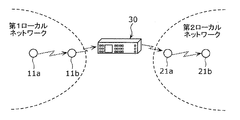
図1に示すように、照明システム1は、無線通信機能を有する、複数の照明装置、通信装置30等により構成されている。この照明システム1では、複数の照明装置のうち、互いに隣り合う照明装置が無線通信することで無線通信経路を構築したローカルネットワークを構成している。ここでいうローカルネットワークとは、照明装置同士で無線通信経路を構築しているネットワークのことをいう。照明システム1は、通信システムの一例である。
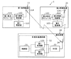
As shown in FIG. 1, the
照明システム1は、第1ローカルネットワーク10と、第2ローカルネットワーク20と、通信装置30とを有する。第1ローカルネットワーク10内での通信プロトコルと、第2ローカルネットワーク20内での通信プロトコルとが異なっている場合に、照明システム1では、光の色相、色温度等といった調光制御及び調色制御の1つ又は複数を組み合わせて照明装置が点灯する点灯シーンを示す制御コマンド等の情報を、第1ローカルネットワーク10と第2ローカルネットワーク20とが共有することを可能にする。第1ローカルネットワーク10は、第1ネットワークの一例である。第2ローカルネットワーク20は、第2ネットワークの一例である。
The
なお、本実施の形態では、第1ローカルネットワーク10と第2ローカルネットワーク20とが通信装置30を介して無線通信で接続しているが、第1ローカルネットワーク10の代わりに1つのメッシュネットワークである第1メッシュネットワークを用いてもよく、第2ローカルネットワーク20の代わりに他のメッシュネットワークである第2メッシュネットワークを用いてもよい。
In the present embodiment, the first
[第1ローカルネットワーク]
第1ローカルネットワーク10は、1以上の第1照明装置11により構成され、第2ローカルネットワーク20と異なるローカルネットワークである。1以上の第1照明装置11のうちの一部の第1照明装置11は、通信装置30と無線通信可能に接続されている。各々の第1照明装置11は、各々の第1照明装置11を操作することが可能な通信端末機と通信可能である。第1ローカルネットワーク10では、第1通信プロトコルの無線通信方式にて、各々の第1照明装置11間で無線通信している。本実施の形態では、第1通信プロトコルは、ZigBee通信である。第1照明装置11は、第1装置の一例である。なお、第1装置は、照明装置に限定しなくてもよく、エアコン、プリンタ、スマートフォン等の装置であってもよい。
[First local network]
The first
各々の第1照明装置11は、例えば、シーリングライト、ダウンライト等であり、天井、壁等の造営材に設置される。図2に示すように、各々の第1照明装置11は、第1発光モジュール111と、第1通信部114と、第1照明制御部112と、第1電源部113とを有する。図2は、実施の形態に係る照明システム1を示すブロック図である。
Each
第1発光モジュール111は、第1照明制御部112により調光制御及び調色制御される。第1発光モジュール111は、基板と、基板に実装された複数の発光素子とを有する。
The first
基板は、複数の発光素子を実装するためのプリント配線基板であり、略矩形状に形成されている。基板としては、例えば、樹脂をベースとする樹脂基板、金属をベースとするメタルベース基板、セラミックからなるセラミック基板等を用いることができる。 The substrate is a printed wiring board for mounting a plurality of light emitting elements, and is formed in a substantially rectangular shape. As the substrate, for example, a resin substrate based on resin, a metal base substrate based on metal, a ceramic substrate made of ceramic, or the like can be used.
発光素子は、基板に実装されている。発光素子は、LED(Light Emitting Diode)素子で構成されている。本実施の形態では、発光素子は、青色光、緑色光及び赤色光を発光するRGBタイプのLED素子である。発光素子は、RGB3色に限られず、RGBW4色であってもよいし、BW2色(青白2色)であってもよい。 The light emitting element is mounted on the substrate. The light emitting element is composed of an LED (Light Emitting Diode) element. In the present embodiment, the light emitting element is an RGB type LED element that emits blue light, green light, and red light. The light emitting elements are not limited to the three RGB colors, but may be four RGBW colors or two BW colors (two blue and white colors).
第1通信部114は、アンテナ及び無線モジュールを有する。複数の第1照明装置11の内の、ある第1照明装置11の第1通信部114は、通信装置30と無線通信することが可能である。第1通信部114は、第2ローカルネットワーク20で設定された点灯シーン等を示す第1制御コマンド等の情報を受信したり、第1ローカルネットワーク10で設定された点灯シーン等を示す第1制御コマンド等の情報を送信したりする。
The
また、第1通信部114は、自身を備える第1照明装置11と異なる第1照明装置11の第1通信部114と、無線通信を行う。これにより、各々の第1照明装置11は、近くに存在する自身以外の他の第1照明装置11と無線通信することができる。無線通信方式としては、例えば、IEEE802.15.1で規格されているWiFi(登録商標)、Bluetooth(登録商標)、ZigBee(登録商標)等のような無線通信方式が用いられる。本実施の形態では、2.4GHz帯の周波数帯を用いて無線通信している。
Moreover, the
本実施の形態では、第1ローカルネットワーク10は、ZigBeeのメッシュルーティングである。ZigBeeでは、ネットワークの構築においてはメッシュルーティングの機能を用いて最適なルートを探して構築する。
In the present embodiment, the first
第1照明制御部112は、第1発光モジュール111、第1通信部114、及び第1電源部113と電気的に接続されている。第1照明制御部112は、例えば第1発光モジュール111の点灯回路を制御することで、第1発光モジュール111から出射させる光を調光制御及び調色制御することができる。
The first
第1照明制御部112は、例えば、CPU(Central Processing Unit)を備えたマイクロコンピュータを用いて構成することができる。第1照明制御部112は、例えばメモリ部に記憶させた適宜のプログラムを実行させることで、所定の照明制御動作を行うことができる。メモリ部は、例えば、フラッシュメモリやEEPROM(Electrically Erasable and Programmable Road Only Memory)などの不揮発性半導体メモリを用いて構成することができる。
The 1st
第1電源部113は、商用電源から供給される交流電力を、整流、平滑及び降圧等して所定レベルの直流電力に変換し、当該直流電力を第1発光モジュール111に供給する構成要素である。
The first
[第2ローカルネットワーク]
第2ローカルネットワーク20は、1以上の第2照明装置21により構成されたネットワークである。1以上の第2照明装置21のうちの一部の第2照明装置21は、通信装置30と無線通信可能に接続されている。各々の第2照明装置21は、各々の第2照明装置21を操作することが可能な通信端末機と通信可能である。第2ローカルネットワーク20では、第1通信プロトコルと異なる第2通信プロトコルの無線通信方式にて、各々の第2照明装置21間で無線通信している。本実施の形態では、第2通信プロトコルは、Bluetooth通信である。第2照明装置21は、第2装置の一例である。なお、第2装置は、照明装置に限定しなくてもよく、エアコン、プリンタ、スマートフォン等の装置であってもよい。
[Second local network]
The second
各々の第2照明装置21は、例えば、シーリングライト、ダウンライト等であり、天井、壁等の造営材に設置される。各々の第2照明装置21は、第2発光モジュール121と、第2通信部124と、第2照明制御部122と、第2電源部123とを有する。
Each of the
第2発光モジュール121は、第2照明制御部122により調光制御及び調色制御される。第2発光モジュール121は、基板と、基板に実装された複数の発光素子とを有する。
The second
基板は、複数の発光素子を実装するためのプリント配線基板であり、略矩形状に形成されている。基板としては、例えば、樹脂をベースとする樹脂基板、金属をベースとするメタルベース基板、セラミックからなるセラミック基板等を用いることができる。 The substrate is a printed wiring board for mounting a plurality of light emitting elements, and is formed in a substantially rectangular shape. As the substrate, for example, a resin substrate based on resin, a metal base substrate based on metal, a ceramic substrate made of ceramic, or the like can be used.
発光素子は、基板に実装されている。発光素子は、LED(Light Emitting Diode)素子で構成されている。本実施の形態では、発光素子は、青色光、緑色光及び赤色光を発光するRGBタイプのLED素子である。発光素子は、RGB3色に限られず、RGBW4色であってもよいし、BW2色(青白2色)であってもよい。 The light emitting element is mounted on the substrate. The light emitting element is composed of an LED (Light Emitting Diode) element. In the present embodiment, the light emitting element is an RGB type LED element that emits blue light, green light, and red light. The light emitting elements are not limited to the three RGB colors, but may be four RGBW colors or two BW colors (two blue and white colors).
第2通信部124は、アンテナ及び無線モジュールを有する。複数の第2照明装置21の内の、ある第2照明装置21の第2通信部124は、通信装置30と無線通信することが可能である。第2通信部124は、第1ローカルネットワーク10で設定された点灯シーン等を示す第1制御コマンド等の情報を受信したり、第2ローカルネットワーク20で設定された点灯シーン等を示す第2制御コマンド等の情報を送信したりする。
The
また、第2通信部124は、自身を備える第2照明装置21と異なる第2照明装置21の第2通信部124と、無線通信を行う。これにより、各々の第2照明装置21は、近くに存在する自身以外の他の第2照明装置21と無線通信することができる。
Moreover, the
無線通信方式としては、例えば、IEEE802.11で規格されているWiFi、IEEE802.15で規格されているBluetooth、ZigBee等のような無線通信方式が用いられる。本実施の形態では、2.4GHz帯の周波数帯を用いて無線通信されている。 As the wireless communication method, for example, a wireless communication method such as WiFi standardized by IEEE 802.11, Bluetooth, ZigBee, etc. standardized by IEEE 802.15 is used. In this embodiment, wireless communication is performed using a frequency band of 2.4 GHz band.
本実施の形態では、第2ローカルネットワーク20は、マネージドフラッティングメッシュと呼ばれるBluetooth meshである。例えば、あるデバイスがブロードキャストでメッセージ(パケット)を送出すると、これを受信したデバイスが周囲のデバイスにブロードキャストで中継して通信可能な全デバイスにメッセージを行き渡らせる。しかし、このままでは、メッセージが溢れてしまうため、例えば、一度送信したメッセージは再度送信しない、又はメッセージの中継回数に制限を設ける等の制御を行う。
In the present embodiment, the second
第2照明制御部122は、第2発光モジュール121、第2通信部124、及び第2電源部123と電気的に接続されている。第2照明制御部122は、例えば第2発光モジュール121の点灯回路を制御することで、第2発光モジュール121から出射させる光を調光制御及び調色制御することができる。
The second
第2照明制御部122は、例えば、CPUを備えたマイクロコンピュータを用いて構成することができる。第2照明制御部122は、例えばメモリ部に記憶させた適宜のプログラムを実行させることで、所定の照明制御動作を行うことができる。
The 2nd
第2電源部123は、商用電源から供給される交流電力を、整流、平滑及び降圧等して所定レベルの直流電力に変換し、当該直流電力を第2発光モジュール121に供給する構成要素である。
The second
[通信装置]
通信装置30は、第1ローカルネットワーク10を構成する1以上の第1照明装置11と、第1ローカルネットワーク10と異なる第2ローカルネットワーク20を構成する1以上の第2照明装置21とを接続するゲートウェイ装置である。通信装置30は、このようなゲートウェイ装置を備えた照明装置であってもよい。
[Communication device]
The
この通信装置30では、一方のローカルネットワークを構成する複数の照明装置のうちの任意の照明装置から情報を受信すると、他方のローカルネットワークを構成する複数の照明装置のうちの終点ノードに情報の伝達、伝達に対する応答等といった所定の処理に専念する。シングルプロトコル状態の詳細については後述する。ここでいう応答は、例えば、ACK(acknowledgement)である。
In the
通信装置30は、第1通信プロトコルで無線通信する第1ローカルネットワーク10と、第1通信プロトコルと異なる第2通信プロトコルで無線通信する第2ローカルネットワーク20と相互に無線通信することが可能である。つまり、通信装置30は、マルチプロトコルによる無線通信を行うことが可能である。なお、本実施の形態では、通信装置30は、1つの制御部32を用いて無線通通信を行う。
The
この通信装置30では、第1ローカルネットワーク10を構成する1以上の第1照明装置11のうちの起点ノードとなる第1照明装置11と、第2ローカルネットワーク20を構成する1以上の第2照明装置21のうちの終点ノードとなる第2照明装置21とのルート確立を行ってもよい。
In the
ここでいう起点ノードとは、情報を終点ノードに伝達する出発地となるノードであり、ソース(Source)とも言う。また、終点ノードは、起点ノードが出力した情報の目的地となるノードであり、ディスティネーション(Destination)とも言う。 The starting point node here is a node that is a starting point for transmitting information to the end point node, and is also referred to as a source. Further, the end point node is a node that is a destination of information output from the start point node, and is also referred to as a destination.
通信装置30は、1つの半導体集積回路32と、第3通信部34と、RF(Radio Frequency)部33とを有する。
The
1つの半導体集積回路32は、1つのICチップである。半導体集積回路32は、マイクロプロセッサ、ROM、RAM等を含んで構成される。半導体集積回路32は、制御部31と、第1処理部131と、第2処理部132とを有する。
One semiconductor integrated
制御部31は、通信装置30が有する第1処理部131、及び第2処理部132等の処理を制御するホストコントローラである。制御部31は、OSI(Open Systems Interconnection)の上位の5層を有する。第1処理部131、及び第2処理部132は、OSIの下位層に含まれる物理層である。
The
第1処理部131は、制御部31及びRF部33との間に接続されている。第1処理部131は、第1通信プロトコルで、第1ローカルネットワーク10を構成する1以上の第1照明装置11と無線通信を行う。第1処理部131は、IPスタックを有していない通信プロトコルを使用する。IPスタックを有していない通信プロトコルは、例えば、ZigBee、Bluetooth等である。IPスタックは、IPを解析することができるIP層である。本実施の形態では、第1処理部131は、ZigBeeの第1通信プロトコルで無線通信を行うためのZigBeeチップである。
The
第1処理部131は、RF部33、及び第3通信部34を介して、第1通信プロトコルで第1照明装置11と無線通信することで、第1照明装置11から例えば第1制御コマンドを受信したり、第1照明装置11に第1制御コマンドを送信したりする。
The
第2処理部132は、制御部31及びRF部33との間で、第1処理部131と並列に接続されている。第2処理部132は、第2通信プロトコルで、第2ローカルネットワーク20を構成する1以上の第2照明装置21と無線通信を行う。つまり、第2処理部132は、第1処理部131と異なる通信プロトコルを用いている。第2処理部132は、IPスタックを有していない通信プロトコルを使用する。本実施の形態では、第2処理部132は、Bluetoothの第2通信プロトコルで無線通信を行うためのBluetoothチップである。
The
第2処理部132は、RF部33、及び第3通信部34を介して、第2通信プロトコルで1以上の第1照明装置11と無線通信することで、1以上の第2照明装置21から例えば第2制御コマンドを受信したり、1以上の第2照明装置21に第2制御コマンドを送信したりする。
The
このことから、制御部31は、第1処理部131に1以上の第1照明装置11と無線通信させることと、第2処理部132に1以上の第2照明装置21と無線通信させることとを切り替える。制御部31は、第1処理部131が1以上の第1照明装置11から第1制御コマンドを受信した場合に、第2処理部132を介して第2通信プロトコルで第1制御コマンドを1以上の第2照明装置21に送信させる。また、制御部31は、第2処理部132が1以上の第2照明装置21から第2制御コマンドを受信した場合に、第1処理部131を介して第1通信プロトコルで第2制御コマンドを1以上の第1照明装置11に送信させる。
Therefore, the
また、制御部31は、第1照明装置11及び第2照明装置21から情報を受信すると、情報の処理に専念するためのシングルプロトコル状態となる。具体的には、制御部31は、第1照明装置11から情報を受信すると、第2照明装置21に対して情報を送信し、当該送信に対する応答を通信装置30が受信するまで、第2処理部132を介して第2ローカルネットワーク20とだけ無線通信を行うシングルプロトコル状態となる。また、制御部31は、第2照明装置21から情報を受信すると、第1照明装置11に対して情報を送信し、当該送信に対する応答を通信装置30が受信するまで、第1処理部131を介して第1ローカルネットワーク10とだけ無線通信を行うシングルプロトコル状態となる。
Moreover, if the
これらにおいて、図3A、図3B、図4A、及び図4Bを用いて説明する。 These will be described with reference to FIGS. 3A, 3B, 4A, and 4B.
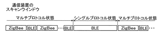
図3Aは、第1ローカルネットワーク10から第2ローカルネットワーク20に向かって情報を伝達したときの模式図である。図3Bは、図3Aにおける通信装置30のスキャンウィンドウを示す模式図である。
FIG. 3A is a schematic diagram when information is transmitted from the first
図3A及び図3Bでは、第1ローカルネットワーク10を構成する2つの第1照明装置11a、11bと第2ローカルネットワーク20を構成する2つの第2照明装置21a、21bとを用いて説明する。なお、第1照明装置11及び第2照明装置21の台数はあくまでも一例であり、この台数に限定されない。起点ノードを第1ローカルネットワーク10の第1照明装置11aとし、終点ノードを第2ローカルネットワーク20の第2照明装置21bとする。起点ノードである第1照明装置11aから終点ノードである第2照明装置21bまでのルートを確立するための情報を、第1照明装置11aが出力する。
3A and 3B, description will be made using two
第1ローカルネットワーク10での情報は、起点ノードを示すソースアドレス、レジストリID、終点ノードを示すディスティネーションアドレス、シーケンスナンバー、TTL(Time to live)及びペイロード等から構成されている。TTLには、デフォルト値とホップカウント値とが含まれる。
The information in the first
まず、照明システム1において、第1ローカルネットワーク10において、第1照明装置11a、第1照明装置11bのこの順番でホップして、第1照明装置11bから通信装置30に情報が伝達されると、制御部31は、第2処理部132を介して第2ローカルネットワーク20とだけ無線通信を行うシングルプロトコル状態となる。つまり、制御部31は、第2通信プロトコルで無線通信を行う状態となり、第1通信プロトコルで無線通信を行わない。
First, in the
通信装置30は、制御部31がシングルプロトコル状態となっている間に、送信先の通信プロトコル以外の通信プロトコルでの無線通信により情報を受信しても、受信した情報を破棄してもよい。また、通信装置30は、終点ノードに送信する情報と異なる情報を、送信先の通信プロトコルと同一の通信プロトコルでの無線通信により受信した場合でも、シングルプロトコル状態となる期間を延長することなく、受信した情報を破棄してもよい。つまり、シングルプロトコル状態では、終点ノードに送信した情報に対する応答以外の情報を受信しても、当該情報の処理を行わない。
While the
なお、通信装置30は、第2ローカルネットワーク20での情報における、ソースアドレス、ディスティネーションアドレス、シーケンスナンバー、TTL等については、第1ローカルネットワーク10での情報におけるソースアドレス、ディスティネーションアドレス、シーケンスナンバー、TTL等をそのまま引き継いでもよい。つまり、通信装置30の制御部31は。第1ローカルネットワーク10から伝達された情報を、引き継いで第2ローカルネットワーク20に伝達してもよい。
Note that the
制御部31が第2処理部132を介して第2ローカルネットワーク20の第2照明装置21aに情報を送信することで、終点ノードの第2照明装置21bに情報が伝達される。第2照明装置21aから第2照明装置21bにホップすると、情報に含まれるディスティネーションアドレスが第2照明装置21bであり、一致する。そして、第2照明装置21bは、起点ノードである第1照明装置11aに対する応答を行う。この場合も同様に、第2ローカルネットワーク20では、第2照明装置21bから第2照明装置21aにホップし、第2照明装置21bから通信装置30にホップする。こうして、第2照明装置21bからの応答が通信装置30に伝達される。
When the
通信装置30が応答を受信すると、制御部31は、第1ローカルネットワーク10及び第2ローカルネットワーク20と無線通信することが可能なマルチプロトコル状態となる。マルチプロトコル状態は、BLE(Bluetooth Low Energy)の第2通信プロトコルで無線通信を行える状態、及びZigBeeの第1通信プロトコルで無線通信を行える状態である。マルチプロトコル状態となる期間では、第1通信プロトコル及び第2通信プロトコルで、間欠的に無線通信を行える。通信装置30は、受信した応答を、第1ローカルネットワーク10で用いられている第1通信プロトコルで第1照明装置11aに伝達する。
When the
また、制御部31は、規定期間以内に情報に対する応答を受信しない場合、第1ローカルネットワーク10及び第2ローカルネットワーク20と無線通信することが可能なマルチプロトコル状態になる。情報を終点ノードに伝達してから規定期間が経過している場合は、終点ノードに情報が伝達されていないこと、又は情報が伝達されているが応答が来ないことが考えられる。タイムアウトとなる規定期間を設けることで、通信装置30では制御部31の処理が滞ることを抑制する。
Further, when the
さらに、制御部31は、第1照明装置11から情報を受信した後に、第2照明装置21に対して情報を送信してから当該送信に対する応答を通信装置30が受信するまでの規定期間を、1ホップ当たりに必要な時間とホップ数とに基づいて算出する。また、制御部31は、第2照明装置21から情報を受信した後に、第1照明装置11に対して情報を送信してから当該送信に対する応答を通信装置30が受信するまでの規定期間を、1ホップ当たりに必要な時間とホップ数とに基づいて算出する。例えば、1ホップ当たりに必要な時間をtとし、ホップ数をnとすると、規定期間は、t×nと算出できる。
Furthermore, after receiving information from the
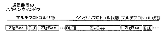
図4Aは、第2ローカルネットワーク20から第1ローカルネットワーク10に向かって情報を伝達したときの模式図である。図4Bは、図4Aにおける通信装置30のスキャンウィンドウを示す模式図である。
FIG. 4A is a schematic diagram when information is transmitted from the second
図4A及び図4Bでも図3A及び図3Bと同様の設定である。ここでは、起点ノードを第2ローカルネットワーク20の第2照明装置12bとし、終点ノードを第1ローカルネットワーク10の第1照明装置11aとする。起点ノードである第2照明装置12bから終点ノードである第1照明装置11aまでのルートを確立するための情報を、第2照明装置12bが出力し、第1照明装置11aまで伝達する。図4A及び図4Bは、図3A及び図3Bと処理が反対となっているだけで、同様の処理を行っているため、その説明を省略する。
4A and 4B have the same settings as in FIGS. 3A and 3B. Here, the starting node is the second lighting device 12b of the second
制御部31の説明に戻る。本実施の形態では、第1照明装置11と通信装置30との間でZigBee通信を行う場合、制御部31は、第1処理部131が1以上の第1照明装置11から取得した第1制御コマンドを取得する。制御部31は、第1処理部131がZigBee通信で取得した第1制御コマンドを、第2処理部132に出力する。第2処理部132は、Bluetooth通信で1以上の第2照明装置21に、取得した第1制御コマンドを送信する。
Returning to the description of the
また、制御部31は、第1処理部131を用いた無線通信と、第2処理部132を用いた無線通信とを排他的に行う。具体的には、第1処理部131と第2処理部132とは、一定の受信間隔と受信期間とによって制御コマンドを間欠的に受信している(後述する図6)。本実施の形態では、第1処理部131が第1制御コマンドを受信可能とする受信期間を「スキャンウィンドウ」と呼び、スキャンウィンドウの受信間隔を「スキャンインターバル」と呼ぶ。第2処理部132においても同様である。本実施の形態では、第1処理部131及び第2処理部132のスキャンウィンドウは排他的である。当然のことながら、通信装置30は、スキャンインターバルごとに制御コマンドを間欠的に送信しているため、スキャンウィンドウが、制御コマンドの送信時間と重ならなければ通信装置30が制御コマンドを受信できない。このことから、本実施の形態では、1以上の第1照明装置11と通信装置30との間でのZigBee通信と、1以上の第2照明装置21と通信装置30との間でのBluetooth通信とが、排他的かつ交互に行われる。なお、単に制御コマンドという場合は、第1制御コマンド及び第2制御コマンドを包含した総称として用いる。
In addition, the
第3通信部34は、RF部33に接続されている。第3通信部34は、1以上の第1照明装置11及び1以上の第2照明装置21から制御コマンドを受信したり、1以上の第1照明装置11及び1以上の第2照明装置21に制御コマンドを送信したりする無線通信用のアンテナである。また、第3通信部34は、第1通信部114と無線通信したり、第2通信部124と無線通信したりすることができる。
The
RF部33は、第1処理部131及び第2処理部132から、制御コマンドを取得すれば、フィルタリング、増幅等を行って第3通信部34に出力する。また、RF部33は、第3通信部34で受信された1以上の第1照明装置11からの第1制御コマンドをフィルタリングして、第1処理部131に出力したり、1以上の第2照明装置21からの第2制御コマンドをフィルタリングして、第2処理部132に出力したりする。
When the
RF部33は、送信回路と、受信回路とを有する。送信回路は、例えば送信する制御コマンドについて、制御コマンドが示す送信帯域の信号を抽出する送信フィルタ、送信フィルタを通過後の信号を高周波信号にアップコンバートする送信ミキサ、アップコンバート後の高周波信号を増幅するプリアンプ等を有する。受信回路は、例えば第3通信部34が受信した1以上の第1照明装置11及び1以上の第2照明装置21からの高周波信号を低周波数信号に変換する受信ミキサ等を有する。
The
なお、通信装置30は、一例であり、照明装置に限定しなくてもよく、スピーカー、エアコン、プリンタ、スマートフォン等の装置に内蔵されるものであってもよく、照明装置に限定されるものではない。
The
[動作]
次に、照明システム1の動作について説明する。
[Operation]
Next, the operation of the
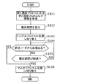
図5は、実施の形態に係る通信装置30の動作を説明するフローチャートである。
図5において、第1ローカルネットワーク10での第1通信プロトコルはZigBeeであり、第2ローカルネットワーク20での第2通信プロトコルはBluetoothである。また、現状では、通信装置30は、マルチプロトコル状態となっていると想定する。
FIG. 5 is a flowchart for explaining the operation of the
In FIG. 5, the first communication protocol in the first
図5に示すように、まず、通信装置30は、第1通信プロトコル又は第2通信プロトコルで情報を受信する(S101)。具体的には、図3Aで示す場合、通信装置30は、第1照明装置11a、第1照明装置11bのこの順番でホップした情報を、第1照明装置11bから受信する。また、図4Aで示す場合、通信装置30は、第2照明装置21b、第2照明装置21aのこの順番でホップした情報を、第2照明装置21aから受信する。
As shown in FIG. 5, first, the
次に、通信装置30は、1ホップ当たりに必要な時間とホップ数とに基づいて、規定期間を算出する(S102)。具体的には、制御部31は、第1照明装置11から情報を受信した後に、第2照明装置21に対して情報を送信してから当該送信に対する応答を通信装置30が受信するまでの規定期間を、1ホップ当たりに必要な時間とホップ数とに基づいて算出する。また、制御部31は、第2照明装置21から情報を受信した後に、第1照明装置11に対して情報を送信してから当該送信に対する応答を通信装置30が受信するまでの規定期間を、1ホップ当たりに必要な時間とホップ数とに基づいて算出する。なお、規定期間の算出は、ステップS104までに行われておればよく、ステップS102でのタイミングに限定されない。
Next, the
次に、通信装置30は、情報を受信すると、送信先の通信プロトコルでの無線通信しか行わないシングルプロトコル状態となる(S103)。具体的には、図3A及び図3Bの通信装置30は、第1通信プロトコルで情報を受信すると、第2通信プロトコルで第2ローカルネットワーク20とだけ無線通信を行うシングルプロトコル状態となる(マルチプロトコル状態からシングルプロトコル状態に切り替わる)。この場合、通信装置30は、送信先である第2ローカルネットワーク20の第2通信プロトコル以外の通信プロトコルで無線通信を行わない。また、図4A及び図4Bの通信装置30は、第2通信プロトコルで情報を受信すると、第1通信プロトコルで第1ローカルネットワーク10とだけ無線通信を行うシングルプロトコル状態となる。この場合、通信装置30は、送信先である第1ローカルネットワーク10の第1通信プロトコル以外の通信プロトコルで無線通信を行わない。通信装置30は、シングルプロトコル状態の間に、通信装置30からの情報の送信、第2照明装置21bの応答の受信等に関する処理を行う。
Next, when receiving the information, the
次に、通信装置30は、終点ノードからの応答があるか否かを判断する(S104)。
Next, the
終点ノードからの応答がある場合(S104でYES)、通信装置30は、シングルプロトコル状態からマルチプロトコル状態に切り替える(S106)。そして、通信装置30は、この処理を終了する。
When there is a response from the end node (YES in S104), the
また、終点ノードからの応答がない場合(S104でNO)、通信装置30は、情報を終点ノードに伝達してから規定期間が経過したか否かを判断する(S105)。
If there is no response from the end node (NO in S104), the
情報を終点ノードに伝達してから規定期間が経過している場合(S105でYES)、通信装置30は、規定期間が経過すると、シングルプロトコル状態からマルチプロトコル状態に切り替える(S106)。そしてこのフローを終了する。
If the specified period has elapsed since the information was transmitted to the end node (YES in S105), the
一方、情報を終点ノードに伝達してから規定期間が経過していない場合(S105でNO)、通信装置30は、ステップS104に戻り同様の処理を行う。
On the other hand, when the specified period has not elapsed since the information was transmitted to the end point node (NO in S105), the
次に、照明システム1の動作について説明する。
Next, the operation of the
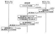
図6は、実施の形態に係る照明システム1の通信装置30の動作を示す説明図である。図7は、実施の形態に係る照明システム1の動作を示すシーケンス図である。
FIG. 6 is an explanatory diagram illustrating an operation of the
図7に示すように、ここでは、ユーザが操作端末を介して操作することで、第1ローカルネットワーク10を構成する1以上の第1照明装置11から第2ローカルネットワーク20を構成する1以上の第2照明装置21に、情報の一例である第1制御コマンドが送信される場合を例に挙げて説明する。
As shown in FIG. 7, here, one or more
まず、通信装置30は、1以上の第1照明装置11に対して、ユーザが設定した第1ローカルネットワーク10を構成する1以上の第1照明装置11の点灯シーンを示す第1制御コマンドを取得するために、1以上の第1照明装置11に対してリクエストの送信を行う(S11)。具体的には、制御部31は、第3通信部34を介して、1以上の第1照明装置11にリクエストを送信する。
First, the
次に、図6及び図7に示すように、1以上の第1照明装置11は、第1通信部114を介して、通信装置30から送信されたリクエストを受信すると、通信装置30に第1制御コマンドを送信する(S1)。
Next, as illustrated in FIGS. 6 and 7, when the one or more
次に、通信装置30は、第1制御コマンドを受信する。通信装置30の制御部31は、第1通信プロトコルでの無線通信を、第2通信プロトコルでの無線通信に切り替える(S12)。つまり、制御部31は、第1処理部131に1以上の第1照明装置11と通信装置30とがZigBee通信することで取得した第1制御コマンドを、第2処理部132にBluetooth通信で第2ローカルネットワーク20を構成する1以上の第2照明装置21に送信させる。なお、ここで、通信装置30は、受信した第1制御コマンドをメモリ等の記憶部に記憶して、自身も第1制御コマンドが示す点灯シーンで点灯する。
Next, the
次に、制御部31は、第3通信部34を介して1以上の第1照明装置11から受信した第1制御コマンドを、第2処理部132に第2通信プロトコルで第2ローカルネットワーク20を構成する1以上の第2照明装置21に送信させる(S13)。つまり、第2処理部132は、第3通信部34を介して、第1制御コマンドを第2通信プロトコルで1以上の第2照明装置21に送信する。
Next, the
次に、1以上の第2照明装置21は、第2通信部124を介して、第1制御コマンドを通信装置30から受信する(S21)。そして、この処理は終了する。
Next, the one or more
ここでは、第2ローカルネットワーク20を構成する1以上の第2照明装置21から第1ローカルネットワーク10を構成する1以上の第1照明装置11に制御コマンドを送信する場合を例に挙げて説明する。
Here, a case where a control command is transmitted from one or more
図8は、実施の形態に係る照明システム1の動作を示すシーケンス図である。
FIG. 8 is a sequence diagram illustrating an operation of the
図8に示すように、まず、通信装置30は、1以上の第2照明装置21に対して、ユーザが設定した第2ローカルネットワーク20を構成する1以上の第2照明装置21の点灯シーンを示す第2制御コマンドを取得するために、1以上の第2照明装置21に対してリクエストの送信を行う(S11)。第2制御コマンドは、情報の一例である
次に、1以上の第2照明装置21は、第2通信部124を介して、通信装置30から送信されたリクエストを受信すると、通信装置30に第2制御コマンドを送信する(S221)。
As shown in FIG. 8, first, the
次に、通信装置30は、第2制御コマンドを受信する。通信装置30の制御部31は、第2通信プロトコルでの無線通信を、第1通信プロトコルでの無線通信に切り替える(S212)。つまり、制御部31は、第2処理部132に1以上の第2照明装置21と通信装置30とがBluetooth通信することで取得した第2制御コマンドを、第1処理部131にZigBee通信で第1ローカルネットワーク10を構成する1以上の第1照明装置11に送信させる。なお、ここで、通信装置30は、受信した第2制御コマンドをメモリ等の記憶部に記憶して、自身も第2制御コマンドが示す点灯シーンで点灯する。
Next, the
次に、制御部31は、第3通信部34を介して1以上の第2照明装置21から受信した第2制御コマンドを、第1処理部131に第1通信プロトコルで、第1ローカルネットワーク10を構成する1以上の第1照明装置11に送信させる(S13)。つまり、第1処理部131は、第3通信部34を介して、第2制御コマンドを第1通信プロトコルで1以上の第1照明装置11に送信する。
Next, the
次に、1以上の第1照明装置11は、第1通信部114を介して、第2制御コマンドを通信装置30から受信する(S201)。そして、この処理は終了する。
Next, the one or more
こうして、図7及び図8に示すように、この照明システム1では、互いに異なる第1ローカルネットワーク10と第2ローカルネットワーク20とを無線通信することができる。
Thus, as shown in FIGS. 7 and 8, in the
[作用効果]
次に、本実施の形態おける通信装置30の作用効果について説明する。
[Function and effect]
Next, the effect of the
上述したように、本実施の形態に係る通信装置30は、第1ローカルネットワーク10を構成する1以上の第1照明装置11と、第1ローカルネットワーク10と異なる第2ローカルネットワーク20を構成する1以上の第2照明装置21との間で情報の伝達を行う。通信装置30は、第1通信プロトコルで1以上の第1照明装置11と無線通信する第1処理部131と、第1通信プロトコルと異なる第2通信プロトコルで1以上の第2照明装置21と無線通信する第2処理部132と、第1処理部131に1以上の第1照明装置11と無線通信させることと、第2処理部132に1以上の第2照明装置21と無線通信させることとを切り替える制御部31とを備える。制御部31は、さらに、第1照明装置11から情報を受信すると、第2照明装置21に対して情報を送信し、当該送信に対する応答を通信装置30が受信するまで、第2処理部132を介して第2ローカルネットワーク20とだけ無線通信を行うシングルプロトコル状態となる。また、制御部31は、第2照明装置21から情報を受信すると、第1照明装置11に対して情報を送信し、当該送信に対する応答を通信装置30が受信するまで、第1処理部131を介して第1ローカルネットワーク10とだけ無線通信を行うシングルプロトコル状態となる。そして、制御部31は、通信装置30が応答を受信すると、第1ローカルネットワーク10及び第2ローカルネットワーク20と無線通信することが可能なマルチプロトコル状態となる。
As described above, the
例えば、第1通信プロトコル及び第2通信プロトコルで間欠的に無線通信を行うマルチプロトコル状態では、応答の取りこぼしが発生する恐れがある。一例を挙げれば、第1通信プロトコルで第1照明装置11に対して情報を送信した場合に、第1通信プロトコルで応答を受信する必要があるが、スキャンウィンドウが第2通信プロトコルである場合には、応答の取りこぼしが発生することがある。
For example, in a multi-protocol state in which wireless communication is intermittently performed using the first communication protocol and the second communication protocol, there is a possibility that a response may be missed. For example, when information is transmitted to the
しかし、本実施の形態によれば、通信装置30が第1照明装置11から情報を受信する又は第2照明装置21から情報を受信することで、制御部31は、第1処理部131を介して第1ローカルネットワーク10とだけ無線通信を行う、又は第2処理部132を介して第2ローカルネットワーク20とだけ無線通信を行うシングルプロトコル状態となる。また、制御部31は、通信装置30が応答を受信すると、第1ローカルネットワーク10及び第2ローカルネットワーク20と無線通信することが可能なマルチプロトコル状態となる。このように、制御部31は、一方のネットワークからの情報を受信すると、送信先のネットワークからの応答を受信するまでの処理に専念するシングルプロトコル状態となるため、その間に安定的な処理を行うことができる。
However, according to the present embodiment, when the
したがって、この通信装置30では、ネットワーク通信において安定的な処理を行うことができる。
Therefore, the
特に、この通信装置30では、シングルプロトコル状態の間に他方のネットワークからの情報を受信せずに、1つずつの処理に専念するため、複数の処理を同時に行う場合に比べて、処理に対する負荷が軽減されるため、処理速度の低下を抑制することができる。
In particular, the
また、本実施の形態に係る通信装置30において、制御部31は、規定期間以内に情報に対する応答を受信しない場合、第1ローカルネットワーク10及び第2ローカルネットワーク20と無線通信することが可能なマルチプロトコル状態になる。
Further, in the
これによれば、制御部31は、規定期間が経過しても応答を受信できない場合に、シングルプロトコル状態からマルチプロトコル状態に切り替えることで、処理速度の低下を抑制することができる。つまり、通信装置30では、第1ローカルネットワーク10及び第2ローカルネットワーク20と無線通信することが可能なマルチプロトコル状態に戻すことで、別の情報の処理を行うことができるため、処理が滞ることを抑制することでできる。
According to this, the
また、本実施の形態に係る通信装置30において、制御部31は、さらに、第1照明装置11から情報を受信した後に、第2照明装置21に対して情報を送信してから当該送信に対する応答を通信装置30が受信するまでの規定期間を、1ホップ当たりに必要な時間とホップ数とに基づいて算出する。そして、制御部31は、第2照明装置21から情報を受信した後に、第1照明装置11に対して情報を送信してから当該送信に対する応答を通信装置30が受信するまでの規定期間を、1ホップ当たりに必要な時間とホップ数とに基づいて算出する。
Further, in
これによれば、制御部31が1ホップ当たりに必要な時間とホップ数とに基づいて規定期間を算出することで、規定期間を最適化することができる。このため、通信装置30では、処理速度の低下を抑制することができる。
According to this, the regulation period can be optimized by calculating the regulation period based on the time required per hop and the number of hops. For this reason, in the
(その他変形例等)
以上、本開示について、実施の形態に基づいて説明したが、本開示は、上記通信装置に限定されるものではない。
(Other variations)
While the present disclosure has been described based on the embodiments, the present disclosure is not limited to the communication device.
例えば、上記各実施の形態に係る通信装置において、第3照明制御部は、半導体集積回路に接続されていることを図2で図示しているが、これに限定されず、RF部と接続されていてもよい。この場合、RF部から制御コマンドを取得することができる。 For example, in the communication device according to each of the above embodiments, the third illumination control unit is illustrated in FIG. 2 as being connected to the semiconductor integrated circuit, but is not limited thereto, and is connected to the RF unit. It may be. In this case, a control command can be acquired from the RF unit.
また、上記各実施の形態に係る通信装置において、第1処理部及び第2処理部とRF部との間にバッファを設けてもよい。バッファは、伝達元の1以上の第1照明装置から受信した情報を、転送先の1以上の第2照明装置に転送するまで、一時的に記憶してもよく、1以上の第2照明装置に情報を伝達する場合にバッファの情報を消去してもよい。バッファは、伝達元の1以上の第2照明装置から受信した情報を、転送先の1以上の第1照明装置に転送するまで、一時的に記憶してもよく、1以上の第1照明装置に情報を伝達する場合にバッファの情報を消去してもよい。 In the communication device according to each of the above embodiments, a buffer may be provided between the first processing unit, the second processing unit, and the RF unit. The buffer may temporarily store the information received from the one or more first lighting devices of the transmission source until it is transferred to the one or more second lighting devices of the transfer destination, and the one or more second lighting devices The information in the buffer may be deleted when information is transmitted to. The buffer may temporarily store the information received from the one or more second lighting devices of the transmission source until the information is transferred to the one or more first lighting devices of the transfer destination, and the one or more first lighting devices The information in the buffer may be deleted when information is transmitted to.
また、上記各実施の形態に係る通信装置に含まれる各処理部は、典型的に集積回路であるLSIとして実現される。これらは個別に1チップ化されてもよいし、一部又は全てを含むように1チップ化されてもよい。 Each processing unit included in the communication device according to each of the above embodiments is typically realized as an LSI that is an integrated circuit. These may be individually made into one chip, or may be made into one chip so as to include a part or all of them.
また、集積回路化はLSIに限るものではなく、専用回路又は汎用プロセッサで実現してもよい。LSI製造後にプログラムすることが可能なFPGA(Field Programmable Gate Array)、又はLSI内部の回路セルの接続や設定を再構成可能なリコンフィギュラブル・プロセッサを利用してもよい。 Further, the circuit integration is not limited to LSI, and may be realized by a dedicated circuit or a general-purpose processor. An FPGA (Field Programmable Gate Array) that can be programmed after manufacturing the LSI or a reconfigurable processor that can reconfigure the connection and setting of circuit cells inside the LSI may be used.
なお、上記各実施の形態において、各構成要素は、専用のハードウェアで構成されるか、各構成要素に適したソフトウェアプログラムを実行することによって実現されてもよい。各構成要素は、CPU又はプロセッサなどのプログラム実行部が、ハードディスク又は半導体メモリなどの記録媒体に記録されたソフトウェアプログラムを読み出して実行することによって実現されてもよい。 In each of the above embodiments, each component may be configured by dedicated hardware or may be realized by executing a software program suitable for each component. Each component may be realized by a program execution unit such as a CPU or a processor reading and executing a software program recorded on a recording medium such as a hard disk or a semiconductor memory.
また、上記で用いた数字は、全て本開示を具体的に説明するために例示するものであり、本開示の実施の形態は例示された数字に制限されない。 Moreover, all the numbers used above are illustrated for specifically explaining the present disclosure, and embodiments of the present disclosure are not limited to the illustrated numbers.
また、ブロック図における機能ブロックの分割は一例であり、複数の機能ブロックを一つの機能ブロックとして実現したり、一つの機能ブロックを複数に分割したり、一部の機能を他の機能ブロックに移してもよい。また、類似する機能を有する複数の機能ブロックの機能を単一のハードウェア又はソフトウェアが並列又は時分割に処理してもよい。 In addition, division of functional blocks in the block diagram is an example, and a plurality of functional blocks can be realized as one functional block, a single functional block can be divided into a plurality of functions, or some functions can be transferred to other functional blocks. May be. In addition, functions of a plurality of functional blocks having similar functions may be processed in parallel or time-division by a single hardware or software.
また、フローチャートにおける各ステップが実行される順序は、本開示を具体的に説明するために例示するためであり、上記以外の順序であってもよい。また、上記ステップの一部が、他のステップと同時(並列)に実行されてもよい。 Further, the order in which the steps in the flowchart are executed is for the purpose of illustrating the present disclosure specifically, and may be in an order other than the above. Also, some of the above steps may be executed simultaneously (in parallel) with other steps.
その他、実施の形態に対して当業者が思いつく各種変形を施して得られる形態、本開示の趣旨を逸脱しない範囲で実施の形態における構成要素及び機能を任意に組み合わせることで実現される形態も本開示に含まれる。 In addition, this embodiment includes a form obtained by making various modifications conceived by those skilled in the art to the embodiment, and a form realized by arbitrarily combining the components and functions in the embodiment without departing from the gist of the present disclosure. Included in the disclosure.
10 第1ローカルネットワーク(第1ネットワーク)
11、11a、11b 第1照明装置(第1装置)
20 第2ローカルネットワーク(第2ネットワーク)
21、21a、21b 第2照明装置(第2装置)
30 通信装置
31 制御部
131 第1処理部
132 第2処理部
10 First local network (first network)
11, 11a, 11b First lighting device (first device)
20 Second local network (second network)
21, 21a, 21b Second illumination device (second device)
30
Claims (3)
第1通信プロトコルで前記1以上の第1装置と無線通信する第1処理部と、
前記第1通信プロトコルと異なる第2通信プロトコルで前記1以上の第2装置と無線通信する第2処理部と、
前記第1処理部に前記1以上の第1装置と無線通信させることと、前記第2処理部に前記1以上の第2装置と無線通信させることとを切り替える制御部とを備え、
前記制御部は、さらに、
前記第1装置から情報を受信すると、前記第2装置に対して情報を送信し、当該送信に対する応答を前記通信装置が受信するまで、前記第2処理部を介して前記第2ネットワークとだけ無線通信を行うシングルプロトコル状態となり、
前記第2装置から情報を受信すると、前記第1装置に対して情報を送信し、当該送信に対する応答を前記通信装置が受信するまで、前記第1処理部を介して前記第1ネットワークとだけ無線通信を行うシングルプロトコル状態となり、
前記通信装置が応答を受信すると、前記第1ネットワーク及び前記第2ネットワークと無線通信することが可能なマルチプロトコル状態となる
通信装置。 A communication device for transmitting information between one or more first devices constituting a first network and one or more second devices constituting a second network different from the first network,
A first processing unit that wirelessly communicates with the one or more first devices using a first communication protocol;
A second processing unit that wirelessly communicates with the one or more second devices using a second communication protocol different from the first communication protocol;
A control unit that switches between causing the first processing unit to wirelessly communicate with the one or more first devices and causing the second processing unit to wirelessly communicate with the one or more second devices;
The control unit further includes:
When information is received from the first device, information is transmitted to the second device, and wirelessly only with the second network through the second processing unit until the communication device receives a response to the transmission. It becomes a single protocol state to communicate,
When information is received from the second device, the information is transmitted to the first device, and wirelessly only with the first network via the first processing unit until the communication device receives a response to the transmission. It becomes a single protocol state to communicate,
When the communication device receives a response, the communication device enters a multi-protocol state capable of wirelessly communicating with the first network and the second network.
請求項1に記載の通信装置。 The communication apparatus according to claim 1, wherein the control unit is in a multi-protocol state capable of wirelessly communicating with the first network and the second network when a response to information is not received within a specified period.
前記第1装置から情報を受信した後に、前記第2装置に対して情報を送信してから当該送信に対する応答を前記通信装置が受信するまでの前記規定期間を、1ホップ当たりに必要な時間とホップ数とに基づいて算出し、
前記第2装置から情報を受信した後に、前記第1装置に対して情報を送信してから当該送信に対する応答を前記通信装置が受信するまでの前記規定期間を、1ホップ当たりに必要な時間とホップ数とに基づいて算出する
請求項2に記載の通信装置。 The control unit further includes:
After the information is received from the first device, the prescribed period from when the information is transmitted to the second device until the communication device receives a response to the transmission is the time required per hop. Based on the number of hops,
After the information is received from the second device, the prescribed period from when the information is transmitted to the first device until the communication device receives a response to the transmission is the time required per hop The communication device according to claim 2, wherein the communication device is calculated based on the number of hops.
Priority Applications (5)
| Application Number | Priority Date | Filing Date | Title |
|---|---|---|---|
| JP2018063322A JP7113246B2 (en) | 2018-03-28 | 2018-03-28 | Communication device |
| US16/355,295 US10709002B2 (en) | 2018-03-28 | 2019-03-15 | Communications device |
| CN201910222626.XA CN110324305B (en) | 2018-03-28 | 2019-03-22 | Communication device |
| DE102019107344.8A DE102019107344A1 (en) | 2018-03-28 | 2019-03-22 | COMMUNICATION DEVICE |
| TW108110245A TWI732198B (en) | 2018-03-28 | 2019-03-25 | Communication device |
Applications Claiming Priority (1)
| Application Number | Priority Date | Filing Date | Title |
|---|---|---|---|
| JP2018063322A JP7113246B2 (en) | 2018-03-28 | 2018-03-28 | Communication device |
Publications (2)
| Publication Number | Publication Date |
|---|---|
| JP2019176352A true JP2019176352A (en) | 2019-10-10 |
| JP7113246B2 JP7113246B2 (en) | 2022-08-05 |
Family
ID=67910116
Family Applications (1)
| Application Number | Title | Priority Date | Filing Date |
|---|---|---|---|
| JP2018063322A Active JP7113246B2 (en) | 2018-03-28 | 2018-03-28 | Communication device |
Country Status (5)
| Country | Link |
|---|---|
| US (1) | US10709002B2 (en) |
| JP (1) | JP7113246B2 (en) |
| CN (1) | CN110324305B (en) |
| DE (1) | DE102019107344A1 (en) |
| TW (1) | TWI732198B (en) |
Citations (3)
| Publication number | Priority date | Publication date | Assignee | Title |
|---|---|---|---|---|
| JP2004015746A (en) * | 2002-06-11 | 2004-01-15 | Sony Corp | Communication method and communication equipment |
| JP2010103785A (en) * | 2008-10-24 | 2010-05-06 | Toshiba Corp | Equipment cooperation system, equipment cooperation method |
| JP2012209905A (en) * | 2011-03-30 | 2012-10-25 | Oki Electric Ind Co Ltd | Wireless communication device, method, and program |
Family Cites Families (30)
| Publication number | Priority date | Publication date | Assignee | Title |
|---|---|---|---|---|
| JP4298651B2 (en) | 2002-05-31 | 2009-07-22 | コーニンクレッカ フィリップス エレクトロニクス エヌ ヴィ | Message routing method, wireless network and master node |
| CN1953406B (en) * | 2005-10-19 | 2011-06-01 | 株式会社Ntt都科摩 | A method to access hybrid network and gateway equipment, wireless terminal and communication system |
| US8491159B2 (en) * | 2006-03-28 | 2013-07-23 | Wireless Environment, Llc | Wireless emergency lighting system |
| CN101971642B (en) * | 2008-01-28 | 2014-03-12 | 松下电器产业株式会社 | Communication system |
| US20120235579A1 (en) * | 2008-04-14 | 2012-09-20 | Digital Lumens, Incorporated | Methods, apparatus and systems for providing occupancy-based variable lighting |
| US10539311B2 (en) * | 2008-04-14 | 2020-01-21 | Digital Lumens Incorporated | Sensor-based lighting methods, apparatus, and systems |
| WO2009129232A1 (en) * | 2008-04-14 | 2009-10-22 | Digital Lumens Incorporated | Modular lighting systems |
| US8255487B2 (en) * | 2008-05-16 | 2012-08-28 | Integrated Illumination Systems, Inc. | Systems and methods for communicating in a lighting network |
| EP3089558A3 (en) * | 2008-11-26 | 2017-01-18 | Wireless Environment, LLC | Wireless lighting devices and applications |
| KR20120099794A (en) * | 2009-12-28 | 2012-09-11 | 인터디지탈 패튼 홀딩스, 인크 | Machine-to-machine gateway architecture |
| JP6276183B2 (en) * | 2011-09-15 | 2018-02-07 | フィッシャー−ローズマウント システムズ,インコーポレイテッド | Transmission of data frames across communication networks using incompatible network routing protocols |
| US10285241B2 (en) * | 2011-10-06 | 2019-05-07 | A9.Com, Inc. | Wireless lighting device with charging port |
| JP5861108B2 (en) * | 2011-10-24 | 2016-02-16 | パナソニックIpマネジメント株式会社 | Lighting control device, lighting device and lighting system |
| US8547036B2 (en) * | 2011-11-20 | 2013-10-01 | Available For Licensing | Solid state light system with broadband optical communication capability |
| TWI487329B (en) * | 2011-12-27 | 2015-06-01 | Ind Tech Res Inst | Operation method in heterogenous networks and gateway and wireless communication device using the same |
| WO2013101766A1 (en) * | 2011-12-28 | 2013-07-04 | Lutron Electronics Co., Inc. | Load control system having a broadcast controller with a diverse wireless communication system |
| US9538608B2 (en) * | 2012-04-11 | 2017-01-03 | Eminvent, LLC | Systems and apparatuses including alterable characteristics and methods of altering and coordinating such characteristics |
| WO2014026226A1 (en) * | 2012-08-13 | 2014-02-20 | Organic Response Investors Pty Ltd | A lighting control apparatus and process |
| US8922366B1 (en) * | 2013-06-28 | 2014-12-30 | Google Inc. | Reader communication with contact lens sensors and display device |
| US9980351B2 (en) * | 2013-08-12 | 2018-05-22 | Abl Ip Holding Llc | Lighting element-centric network of networks |
| US9326364B2 (en) * | 2014-04-17 | 2016-04-26 | Panasonic Intellectual Property Management Co., Ltd. | Illumination system and illumination device |
| TWI622322B (en) * | 2015-02-13 | 2018-04-21 | 東林科技股份有限公司 | Electric energy supply device with data bridge function and wireless lighting control system including the same |
| JP6575871B2 (en) * | 2016-01-15 | 2019-09-18 | パナソニックIpマネジメント株式会社 | Lighting equipment and lighting system |
| US20170251488A1 (en) * | 2016-02-26 | 2017-08-31 | Comcast Cable Communications, Llc | Network Scheduling For Improved Reliability |
| CN105703988A (en) * | 2016-03-30 | 2016-06-22 | 上海上实龙创智慧能源科技股份有限公司 | WEB-based multiprotocol intelligent household gateway |
| JP6865385B2 (en) * | 2017-02-15 | 2021-04-28 | パナソニックIpマネジメント株式会社 | lighting equipment |
| JP6846665B2 (en) * | 2017-02-15 | 2021-03-24 | パナソニックIpマネジメント株式会社 | lighting equipment |
| JP6876975B2 (en) * | 2017-02-15 | 2021-05-26 | パナソニックIpマネジメント株式会社 | Remote control, lighting system and lighting equipment |
| JP6998567B2 (en) * | 2017-11-29 | 2022-02-04 | パナソニックIpマネジメント株式会社 | Lighting equipment |
| JP2019102900A (en) * | 2017-11-29 | 2019-06-24 | パナソニックIpマネジメント株式会社 | Communication apparatus |
-
2018
- 2018-03-28 JP JP2018063322A patent/JP7113246B2/en active Active
-
2019
- 2019-03-15 US US16/355,295 patent/US10709002B2/en active Active
- 2019-03-22 CN CN201910222626.XA patent/CN110324305B/en active Active
- 2019-03-22 DE DE102019107344.8A patent/DE102019107344A1/en active Pending
- 2019-03-25 TW TW108110245A patent/TWI732198B/en active
Patent Citations (3)
| Publication number | Priority date | Publication date | Assignee | Title |
|---|---|---|---|---|
| JP2004015746A (en) * | 2002-06-11 | 2004-01-15 | Sony Corp | Communication method and communication equipment |
| JP2010103785A (en) * | 2008-10-24 | 2010-05-06 | Toshiba Corp | Equipment cooperation system, equipment cooperation method |
| JP2012209905A (en) * | 2011-03-30 | 2012-10-25 | Oki Electric Ind Co Ltd | Wireless communication device, method, and program |
Also Published As
| Publication number | Publication date |
|---|---|
| US20190306958A1 (en) | 2019-10-03 |
| TW201943252A (en) | 2019-11-01 |
| JP7113246B2 (en) | 2022-08-05 |
| DE102019107344A1 (en) | 2019-10-02 |
| US10709002B2 (en) | 2020-07-07 |
| CN110324305B (en) | 2022-04-15 |
| CN110324305A (en) | 2019-10-11 |
| TWI732198B (en) | 2021-07-01 |
Similar Documents
| Publication | Publication Date | Title |
|---|---|---|
| CN109842608B (en) | Communication device | |
| CN109842972B (en) | Lighting device | |
| US11012534B2 (en) | Node for a multi-hop communication network, related lighting system, method of updating the software of lighting modules and computer-program product | |
| US20230189410A1 (en) | Network diagnostics using color output of lamps | |
| WO2018228883A1 (en) | System and method for relaying single-hop traffic over wireless multi-hop networks | |
| JP7450762B2 (en) | Efficient commissioning of radio control systems | |
| JP7117483B2 (en) | Communication device and communication system | |
| JP2007036665A (en) | Wireless system and method of setting wireless network | |
| JP7113246B2 (en) | Communication device | |
| CN114467318A (en) | Method and apparatus for controlling a temporary gateway for AD-HOC data needs | |
| JP7246016B2 (en) | COMMUNICATION METHOD, PROGRAM AND COMMUNICATION DEVICE | |
| US20230232231A1 (en) | Configuring wireless network using ephemeral gateway | |
| US20230050614A1 (en) | A method of and a coordinator device for selectively commissioning a node device in network | |
| TW202024532A (en) | Communication device, wireless communication device, lighting device, lighting system communication method and memory program of memory media characterized in easily to confirm whether the matched lighting device and the communication device being communicated | |
| WO2023200782A1 (en) | A module of a modular power strip, modular power strip and a method for selecting a module of a modular power strip |
Legal Events
| Date | Code | Title | Description |
|---|---|---|---|
| A621 | Written request for application examination |
Free format text: JAPANESE INTERMEDIATE CODE: A621 Effective date: 20201119 |
|
| A977 | Report on retrieval |
Free format text: JAPANESE INTERMEDIATE CODE: A971007 Effective date: 20211228 |
|
| A131 | Notification of reasons for refusal |
Free format text: JAPANESE INTERMEDIATE CODE: A131 Effective date: 20220111 |
|
| A521 | Request for written amendment filed |
Free format text: JAPANESE INTERMEDIATE CODE: A523 Effective date: 20220308 |
|
| TRDD | Decision of grant or rejection written | ||
| A01 | Written decision to grant a patent or to grant a registration (utility model) |
Free format text: JAPANESE INTERMEDIATE CODE: A01 Effective date: 20220426 |
|
| A61 | First payment of annual fees (during grant procedure) |
Free format text: JAPANESE INTERMEDIATE CODE: A61 Effective date: 20220511 |
|
| R151 | Written notification of patent or utility model registration |
Ref document number: 7113246 Country of ref document: JP Free format text: JAPANESE INTERMEDIATE CODE: R151 |