JP2019014591A - Work machine - Google Patents
Work machine Download PDFInfo
- Publication number
- JP2019014591A JP2019014591A JP2017134440A JP2017134440A JP2019014591A JP 2019014591 A JP2019014591 A JP 2019014591A JP 2017134440 A JP2017134440 A JP 2017134440A JP 2017134440 A JP2017134440 A JP 2017134440A JP 2019014591 A JP2019014591 A JP 2019014591A
- Authority
- JP
- Japan
- Prior art keywords
- hydraulic
- capacity
- command signal
- control valve
- hydraulic motor
- Prior art date
- Legal status (The legal status is an assumption and is not a legal conclusion. Google has not performed a legal analysis and makes no representation as to the accuracy of the status listed.)
- Pending
Links
Images


Abstract
Description
本発明は、吊り荷の巻き上げおよび巻き下げを行うウインチを備えた作業機械に関する。 The present invention relates to a work machine including a winch that winds and unloads a suspended load.
従来、作業機械として、吊り荷の巻き上げ、巻き下げを行うウインチシステムを備えたクレーンが知られている。このようなクレーンでは、吊り荷の吊り上げ中に、油圧回路の配管破損などの異常が生じた場合であっても、吊り荷の落下を防止することが必要とされる。 Conventionally, a crane equipped with a winch system for lifting and lowering a suspended load is known as a work machine. In such a crane, it is necessary to prevent the suspended load from dropping even when an abnormality such as breakage of the piping of the hydraulic circuit occurs during lifting of the suspended load.
特許文献1に開示された技術では、巻き上げ用ウインチを駆動する油圧モータのメータアウト側の流路に、外部パイロット式のカウンタバランス弁が配置されている。このカウンタバランス弁は、メータイン側の作動油の圧力が所定の設定圧以下となった場合に、メータアウト側の流路を絞るように作動する。この結果、配管等の破損によりメータイン側の圧力が低下することを防止するとともに、油圧モータの回転を油圧的に制動することができるため吊り荷の落下が防止される。 In the technique disclosed in Patent Document 1, an external pilot type counter balance valve is arranged in a flow path on the meter-out side of a hydraulic motor that drives a winding winch. This counter balance valve operates to throttle the flow path on the meter-out side when the pressure of the hydraulic oil on the meter-in side becomes equal to or lower than a predetermined set pressure. As a result, it is possible to prevent the pressure on the meter-in side from decreasing due to breakage of the piping and the like, and it is possible to hydraulically brake the rotation of the hydraulic motor, thereby preventing the suspended load from falling.
近年、クレーンなどの作業機械を駆動するシステムとして、省エネ化を目的としたセカンダリーコントロールシステム(Secondary Control System 以下、SCSという)が適用され始めている。SCSは、油圧式の可変容量ポンプと、アクチュエータに連結された油圧式の両傾転可変容量モータとを含む。可変容量ポンプがメイン回路の圧力を一定に維持しながら、可変容量モータの傾転および吐出容量(押しのけ容積)が調整されることで、アクチュエータの位置制御、速度制御およびトルク制御などが実現される。特許文献2には、このようなSCSが油圧ショベルの旋回システムなどに適用された技術が開示されている。 2. Description of the Related Art In recent years, a secondary control system (hereinafter referred to as SCS) that aims to save energy has been applied as a system for driving work machines such as cranes. The SCS includes a hydraulic variable displacement pump and a hydraulic double tilt variable displacement motor connected to an actuator. While the variable displacement pump maintains the pressure of the main circuit constant, the displacement of the variable displacement motor and the discharge displacement (push displacement) are adjusted, thereby realizing actuator position control, speed control, torque control, and the like. . Patent Document 2 discloses a technique in which such SCS is applied to a swing system of a hydraulic excavator.
上記のようなSCSがウインチの駆動回路に適用されることで、従来の回路に存在するコントロールバルブを要することなく、ウインチの駆動が可能となる。この結果、バルブ圧損の低減や動力回生が実現可能とされる。本発明の発明者は、SCSが作業機械のウインチシステムに適用された場合の新たな課題について知見した。当該課題とは、吊り荷の巻き上げまたは巻き下げ作業中に、モータ容量を制御する指令信号に異常が発生すると、吊り荷の落下を直ぐに止めることが難しいという点にある。具体的には、SCSが適用されたウインチシステムでは、モータ容量制御の故障の仕方(制御電流の天絡、地絡等)によって、故障時のモータ容量が異なる。特に、モータの第1ポートに通じる第1メイン油路とモータの第2ポートに通じる第2メイン油路との間で、吊り荷の巻き下げに対応する、メータイン側油路およびメータアウト側油路が反転する可能性がある。したがって、特許文献1に記載の技術のように一つのカウンタバランス弁では、クレーンの使用条件によっては吊り荷の落下を止めることが難しくなる。また、油圧モータが両傾転可変容量式であるために、異常時にモータの容量がゼロの状態で傾転制御が停止する場合がある。この場合、前述のようなカウンタバランス弁によって油圧モータのメータアウト側流路が絞られたとしても、油圧モータにブレーキトルクが発生せず、ウインチを停止させることができない。このように、SCSが適用されたウインチシステムでは、モータ容量を制御する回路に異常が発生すると、吊り荷の落下を直ぐに止めることができないという問題があった。 By applying the SCS as described above to a winch drive circuit, it is possible to drive the winch without requiring a control valve existing in a conventional circuit. As a result, reduction of valve pressure loss and power regeneration can be realized. The inventor of the present invention has found a new problem when the SCS is applied to a winch system of a work machine. The problem is that it is difficult to immediately stop the falling load if an abnormality occurs in the command signal for controlling the motor capacity during the lifting or lowering operation of the suspended load. Specifically, in a winch system to which SCS is applied, the motor capacity at the time of failure differs depending on the way of motor capacity control failure (control current ground fault, ground fault, etc.). In particular, a meter-in side oil passage and a meter-out side oil corresponding to lowering of a suspended load between a first main oil passage leading to the first port of the motor and a second main oil passage leading to the second port of the motor. The road may turn over. Therefore, with the single counter balance valve as in the technique described in Patent Document 1, it is difficult to stop the falling load depending on the use conditions of the crane. In addition, since the hydraulic motor is a double-tilt variable displacement type, tilt control may stop when the motor capacity is zero during an abnormality. In this case, even if the meter-out flow path of the hydraulic motor is throttled by the counter balance valve as described above, the brake torque is not generated in the hydraulic motor and the winch cannot be stopped. As described above, in the winch system to which the SCS is applied, there is a problem that when an abnormality occurs in the circuit that controls the motor capacity, it is not possible to immediately stop the falling load.
本発明は、上記問題に鑑みてなされたものであり、セカンダリーコントロールシステムによって駆動されるウインチドラムを含む作業機械において、可変容量式モータの容量を制御する指令信号に異常が発生した場合に、吊り荷の落下を速やかに阻止することを目的とする。 The present invention has been made in view of the above problems, and in a work machine including a winch drum driven by a secondary control system, when an abnormality occurs in a command signal for controlling the capacity of a variable displacement motor, the suspension is suspended. The purpose is to quickly prevent the fall of the load.
本発明の一の局面に係る作業機械は、吊り荷に接続されるロープと、前記ロープに接続され、軸回りに第1回転方向に回転し前記ロープを巻き取ることで前記吊り荷の巻き上げを行い、前記軸回りに前記第1回転方向とは反対の第2回転方向に回転し前記ロープを繰り出すことで前記吊り荷の巻き下げを行うウインチドラムと、作動油を吐出する可変容量式の油圧ポンプと、前記ウインチドラムに接続される両傾転可変容量式の油圧モータであって、前記油圧ポンプから吐出される作動油を受け入れるとともに作動油を吐出することで、前記油圧モータの容量に応じて前記ウインチドラムを前記第1回転方向および前記第2回転方向に回転させることが可能な両傾転可変容量式の油圧モータと、前記油圧ポンプと前記油圧モータとを連通する第1油路と、前記油圧モータとタンクとを連通する第2油路と、前記吊り荷の巻き上げおよび巻き下げのための操作を受ける被操作部と、前記被操作部が受ける操作量に応じた電流値からなる指令信号を出力する出力部と、前記出力部が出力する前記指令信号が正常状態の場合、当該指令信号に応じて前記油圧モータの容量を制御するとともに、前記指令信号が特定の異常状態になることに連動して、前記油圧モータの容量をゼロよりも大きくかつ前記ウインチドラムに対して前記第1回転方向にトルクを発生させることが可能な非常用容量に設定する、モータ容量制御部と、前記指令信号の前記正常状態および前記異常状態を判定する判定部を含み、前記指令信号が前記異常状態と判定された場合に、前記第1油路および前記第2油路における作動油の流通をそれぞれ遮断する遮断機構と、を備える。 A work machine according to an aspect of the present invention includes a rope connected to a suspended load, the rope connected to the rope, and rotating in a first rotation direction around an axis to wind up the suspended load. A winch drum that rotates around the axis in a second rotation direction opposite to the first rotation direction and unwinds the suspended load by feeding out the rope; and a variable displacement hydraulic pressure that discharges hydraulic oil A bi-tilt variable displacement hydraulic motor connected to the pump and the winch drum, and accepts hydraulic oil discharged from the hydraulic pump and discharges hydraulic oil, so that the hydraulic motor can be adapted to the capacity of the hydraulic motor. The bi-tilt variable displacement hydraulic motor capable of rotating the winch drum in the first rotation direction and the second rotation direction, and the hydraulic pump and the hydraulic motor communicate with each other. One oil passage, a second oil passage communicating the hydraulic motor and the tank, an operated portion that receives operations for lifting and lowering the suspended load, and an operation amount that the operated portion receives When the command signal output from the output unit and the command signal output from the output unit are in a normal state, the capacity of the hydraulic motor is controlled according to the command signal, and the command signal is a specific signal. In conjunction with an abnormal condition, the capacity of the hydraulic motor is set to an emergency capacity that is larger than zero and capable of generating torque in the first rotation direction with respect to the winch drum. A control unit, and a determination unit that determines the normal state and the abnormal state of the command signal. When the command signal is determined to be the abnormal state, the first oil passage and the second oil passage are provided. That and a blocking mechanism for blocking respectively the circulation of the hydraulic oil.
本構成によれば、セカンダリーコントロールシステムによって駆動されるウインチドラムを含む作業機械において、可変容量式の油圧モータの容量を制御する指令信号に異常が発生すると、油圧モータの容量が非常用容量に設定される。当該非常用容量は、ゼロよりも大きくかつウインチドラムに対して吊り荷を巻き上げる回転方向にトルクを発生させる。また、遮断機構は、第1油路および第2油路における作動油の流通をそれぞれ遮断する。この結果、油圧モータは、遮断された第1油路および第2油路のモータ側に残存する作動油を押しのけながら吊り荷を巻き上げる回転方向にトルクを発生し、やがて油圧モータの回転が停止する。このため、ウインチドラムが油圧的に吊り荷を保持することが可能となり、吊り荷の落下を速やかに阻止することできる。 According to this configuration, in a work machine including a winch drum driven by a secondary control system, when an abnormality occurs in a command signal for controlling the capacity of a variable displacement hydraulic motor, the capacity of the hydraulic motor is set to an emergency capacity. Is done. The emergency capacity is greater than zero and generates torque in the rotational direction that winds up the suspended load on the winch drum. Further, the blocking mechanism blocks the flow of hydraulic oil in the first oil passage and the second oil passage, respectively. As a result, the hydraulic motor generates torque in the direction of winding up the suspended load while pushing away the hydraulic oil remaining on the motor side of the blocked first oil passage and second oil passage, and eventually the rotation of the hydraulic motor stops. . For this reason, the winch drum can hydraulically hold the suspended load, and the suspended load can be quickly prevented from falling.
上記の構成において、前記油圧モータは、当該油圧モータの容量を変化させるように移動可能な可動部を有し、前記モータ容量制御部は、前記油圧モータの前記可動部に接続され、作動油を受け入れるとともに作動油を吐出することで前記可動部を駆動する容量制御シリンダと、前記出力部が出力する前記指令信号を受け入れ当該指令信号に応じて前記容量制御シリンダに対する作動油の給排を切り換える電磁方向制御弁と、前記指令信号が前記異常状態になることに連動して、前記油圧モータの容量を前記非常用容量に設定する切換位置に前記電磁方向制御弁を強制的に切り換える非常用切換機構と、を有することが望ましい。 In the above configuration, the hydraulic motor has a movable part that can move so as to change the capacity of the hydraulic motor, and the motor capacity control part is connected to the movable part of the hydraulic motor, A displacement control cylinder that drives the movable part by receiving and discharging hydraulic oil, and an electromagnetic that receives the command signal output from the output unit and switches supply and discharge of hydraulic oil to and from the displacement control cylinder according to the command signal A direction control valve and an emergency switching mechanism for forcibly switching the electromagnetic direction control valve to a switching position for setting the capacity of the hydraulic motor to the emergency capacity in conjunction with the command signal becoming the abnormal state It is desirable to have.
本構成によれば、出力部が出力する指令信号が正常状態の場合、電磁方向制御弁が容量制御シリンダを制御することで、油圧モータの可動部が駆動される。この結果、油圧モータの容量が制御される。また、出力部が出力する指令信号が異常状態の場合、非常用切換機構によって電磁方向制御弁の切換位置が強制的に切り換わり、油圧モータの容量を非常用容量に設定することができる。 According to this configuration, when the command signal output from the output unit is in a normal state, the movable portion of the hydraulic motor is driven by the electromagnetic directional control valve controlling the displacement control cylinder. As a result, the capacity of the hydraulic motor is controlled. Further, when the command signal output from the output unit is in an abnormal state, the switching position of the electromagnetic directional control valve is forcibly switched by the emergency switching mechanism, and the capacity of the hydraulic motor can be set to the emergency capacity.
上記の構成において、前記容量制御シリンダは、前記油圧モータの前記可動部に接続され前記可動部を駆動する第1容量制御シリンダであって、当該第1容量制御シリンダは、シリンダ本体と当該シリンダ本体内を移動可能なピストンと前記ピストンおよび前記可動部に接続されたロッドとを有し、前記ピストンによって前記シリンダ本体内にロッド側油圧室およびヘッド側油圧室がそれぞれ画定されており、前記電磁方向制御弁は、前記出力部が出力する前記指令信号を受け入れ当該指令信号に応じて前記第1容量制御シリンダの前記ロッド側油圧室および前記ヘッド側油圧室に対する作動油の給排を切り換えることで前記ピストンを移動させる第1電磁方向制御弁であって、前記第1電磁方向制御弁は、前記指令信号が前記異常状態としての地絡状態になることに連動して、前記ロッド側油圧室および前記ヘッド側油圧室を互いに連通させる非常用連通位置に切り換わることが可能であり、前記非常用切換機構は、前記指令信号が前記地絡状態になることに連動して、前記油圧モータの容量が前記非常用容量となる位置に前記可動部が移動するように前記ピストンを付勢する第1付勢部材を有することが望ましい。また、前記第1電磁方向制御弁は、前記指令信号が前記異常状態としての天絡状態になることに連動して、前記第1付勢部材が前記ピストンを付勢する方向と同じ方向に前記ピストンを移動させるように前記ロッド側油圧室および前記ヘッド側油圧室に対する作動油の給排を行う非常用給排位置に切り換わることが更に望ましい。 In the above configuration, the displacement control cylinder is a first displacement control cylinder that is connected to the movable portion of the hydraulic motor and drives the movable portion, and the first displacement control cylinder includes a cylinder body and the cylinder body. A piston that is movable inside and a rod connected to the piston and the movable part, and the piston defines a rod-side hydraulic chamber and a head-side hydraulic chamber in the cylinder body, and the electromagnetic direction The control valve receives the command signal output from the output unit, and switches supply / discharge of hydraulic oil to and from the rod-side hydraulic chamber and the head-side hydraulic chamber of the first displacement control cylinder according to the command signal. A first electromagnetic directional control valve for moving a piston, wherein the first electromagnetic directional control valve has the command signal set to the abnormal state; In conjunction with the ground fault state, the rod side hydraulic chamber and the head side hydraulic chamber can be switched to an emergency communication position that allows the rod side hydraulic chamber and the head side hydraulic chamber to communicate with each other. In conjunction with the ground fault state, the hydraulic motor has a first urging member that urges the piston so that the movable portion moves to a position where the capacity of the hydraulic motor becomes the emergency capacity. desirable. In addition, the first electromagnetic directional control valve moves in the same direction as the direction in which the first urging member urges the piston in conjunction with the command signal becoming a power supply state as the abnormal state. It is further desirable to switch to an emergency supply / discharge position for supplying and discharging hydraulic oil to and from the rod side hydraulic chamber and the head side hydraulic chamber so as to move the piston.
本構成によれば、油圧モータの容量を制御する指令信号が地絡した場合、第1電磁方向制御弁が非常用連通位置に切り換わることで、油圧的にピストンを移動させる駆動力が失われる。そして、ピストンに接続された可動部は、第1付勢部材の付勢力によって、油圧モータの容量を非常用容量に設定する位置に移動する。このため、指令信号が地絡した場合でも、油圧モータの容量が確実に非常用容量に設定され、吊り荷の落下を阻止することができる。一方、油圧モータの容量を制御する指令信号が天絡した場合、第1電磁方向制御弁が非常用給排位置に切り換わることで、ピストンに接続された可動部を油圧的に移動させることができる。移動された可動部は、吊り荷を巻き上げることが可能な容量に油圧モータの容量を設定する。このため、指令信号が天絡した場合でも、吊り荷の落下を阻止することができる。 According to this configuration, when the command signal for controlling the capacity of the hydraulic motor has a ground fault, the driving force for hydraulically moving the piston is lost by switching the first electromagnetic direction control valve to the emergency communication position. . And the movable part connected to the piston moves to the position where the capacity of the hydraulic motor is set to the emergency capacity by the urging force of the first urging member. For this reason, even when the command signal has a ground fault, the capacity of the hydraulic motor is reliably set to the emergency capacity, and the suspended load can be prevented from falling. On the other hand, when the command signal for controlling the capacity of the hydraulic motor has a power fault, the movable part connected to the piston can be hydraulically moved by switching the first electromagnetic direction control valve to the emergency supply / discharge position. it can. The moved movable part sets the capacity of the hydraulic motor to a capacity capable of winding up the suspended load. For this reason, even if the command signal has a power fault, the suspended load can be prevented from falling.
上記の構成において、前記モータ容量制御部は、前記油圧モータの前記可動部に接続され前記可動部を駆動する第2容量制御シリンダであって、当該第2容量制御シリンダは、シリンダ本体と当該シリンダ本体内を移動可能なピストンと前記ピストンおよび前記可動部に接続されたロッドとを有し、前記ピストンによって前記シリンダ本体内にロッド側油圧室およびヘッド側油圧室がそれぞれ画定されており、前記電磁方向制御弁は、前記出力部が出力する前記指令信号を受け入れ当該指令信号に応じて前記第2容量制御シリンダの前記ロッド側油圧室および前記ヘッド側油圧室に対する作動油の給排を切り換えることで前記ピストンを移動させる第2電磁方向制御弁であって、前記第2電磁方向制御弁は、前記指令信号が前記異常状態としての地絡状態または天絡状態になることに連動して、前記油圧モータの容量が前記非常用容量となる位置に前記可動部が移動するように、前記ロッド側油圧室および前記ヘッド側油圧室に対する作動油の給排を行う非常用給排位置に切り換わることが可能であり、前記非常用切換機構は、前記指令信号が前記地絡状態または前記天絡状態になることに連動して、前記第2電磁方向制御弁が前記非常用給排位置に切り換わるように当該第2電磁方向制御弁を付勢する第2付勢部材を有するものでもよい。 In the above configuration, the motor capacity control unit is a second capacity control cylinder that is connected to the movable part of the hydraulic motor and drives the movable part, and the second capacity control cylinder includes a cylinder body and the cylinder. A piston movable within the main body, and a rod connected to the piston and the movable part, and the piston defines a rod-side hydraulic chamber and a head-side hydraulic chamber in the cylinder body, and the electromagnetic The direction control valve receives the command signal output from the output unit, and switches supply / discharge of hydraulic oil to / from the rod-side hydraulic chamber and the head-side hydraulic chamber of the second displacement control cylinder according to the command signal. A second electromagnetic directional control valve for moving the piston, wherein the second electromagnetic directional control valve has the command signal in the abnormal state. The rod-side hydraulic chamber and the head-side hydraulic chamber so that the movable portion moves to a position where the capacity of the hydraulic motor becomes the emergency capacity in conjunction with the ground fault state or the power fault state. It is possible to switch to an emergency supply / discharge position that supplies and discharges hydraulic oil to and from the emergency switching mechanism in conjunction with the command signal becoming the ground fault state or the power fault state, You may have a 2nd biasing member which urges | biases the said 2nd electromagnetic direction control valve so that the said 2nd electromagnetic direction control valve may switch to the said emergency supply / discharge position.
本構成によれば、油圧モータの容量を制御する指令信号が地絡または天絡した場合、第2電磁方向制御弁が非常用給排位置に切り換わることで、ピストンに接続された可動部を油圧的に移動させることができる。移動された可動部は、吊り荷を巻き上げることが可能な容量に油圧モータの容量を設定する。このため、指令信号が地絡または天絡した場合でも、吊り荷の落下を阻止することができる。 According to this configuration, when the command signal for controlling the capacity of the hydraulic motor has a ground fault or a power fault, the second electromagnetic directional control valve switches to the emergency supply / discharge position, so that the movable part connected to the piston is It can be moved hydraulically. The moved movable part sets the capacity of the hydraulic motor to a capacity capable of winding up the suspended load. For this reason, even when the command signal has a ground fault or a sky fault, the suspended load can be prevented from falling.
上記の構成において、前記油圧モータの作動特性値を検出する特性値検出部と、前記被操作部が受ける操作量に応じた前記作動特性値の目標値を記憶および出力する記憶部と、を更に有し、前記判定部は、前記特性値検出部が検出する前記作動特性値と前記記憶部が出力する前記目標値とを比較することで、前記指令信号が前記異常状態となったことを判定し、前記遮断機構は、前記判定部によって前記指令信号が前記異常状態となったと判定されると、前記第1油路および前記第2油路における作動油の流通をそれぞれ遮断することが望ましい。 In the above configuration, a characteristic value detection unit that detects an operation characteristic value of the hydraulic motor, and a storage unit that stores and outputs a target value of the operation characteristic value according to an operation amount received by the operated unit. The determination unit determines that the command signal is in the abnormal state by comparing the operation characteristic value detected by the characteristic value detection unit and the target value output by the storage unit. When the determination unit determines that the command signal is in the abnormal state, the blocking mechanism preferably blocks the flow of hydraulic oil in the first oil passage and the second oil passage.
本構成によれば、油圧モータの作動特性値が操作レバーの操作量に応じた目標値と乖離することを利用して、指令信号に異常が発生したことが判定されるとともに、当該判定に基づいて第1油路および第2油路を遮断することができる。 According to this configuration, it is determined that an abnormality has occurred in the command signal using the fact that the operating characteristic value of the hydraulic motor deviates from the target value corresponding to the operation amount of the operation lever, and based on the determination Thus, the first oil passage and the second oil passage can be blocked.
上記の構成において、前記遮断機構は、前記第1油路に配置され、当該第1油路における作動油の流通を許容する流通位置と当該流通を遮断する遮断位置との間で切り換わるように作動する第1方向制御弁と、前記第2油路に配置され、当該第2油路における作動油の流通を許容する流通位置と当該流通を遮断する遮断位置との間で切り換わるように作動する第2方向制御弁と、前記判定部によって前記指令信号が前記異常状態となったと判定されると、前記第1方向制御弁および前記第2方向制御弁をそれぞれ遮断位置に切り換える切換部と、を有するものでもよい。 In the above configuration, the shut-off mechanism is disposed in the first oil passage, and is switched between a flow position allowing the flow of hydraulic oil in the first oil passage and a shut-off position blocking the flow. A first directional control valve that operates, and is disposed in the second oil passage, and operates to switch between a flow position that allows the flow of hydraulic oil in the second oil passage and a blocking position that blocks the flow. A second directional control valve, and a switching unit that switches the first directional control valve and the second directional control valve to a cutoff position when the determination unit determines that the command signal is in the abnormal state, It may have.
本構成によれば、第1油路および第2油路にそれぞれ設けられた第1方向制御弁および第2方向制御弁によって、各油路における作動油の流通と遮断とを容易に切り換えることができる。 According to this configuration, it is possible to easily switch between the flow and shut-off of the hydraulic oil in each oil passage by the first direction control valve and the second direction control valve provided in the first oil passage and the second oil passage, respectively. it can.
本発明によれば、セカンダリーコントロールシステムによって駆動されるウインチドラムを含む作業機械において、可変容量式の油圧モータの容量を制御する指令信号に異常が発生した場合でも、吊り荷の落下を速やかに阻止することができる。 According to the present invention, in a work machine including a winch drum driven by a secondary control system, even when an abnormality occurs in a command signal for controlling the capacity of a variable displacement hydraulic motor, the suspended load is quickly prevented. can do.
以下、図面を参照しつつ、本発明の各実施形態について説明する。図1は、本発明の第1実施形態に係るクレーン10(作業機械)の側面図である。なお、図1には、「上」、「下」、「前」および「後」の方向が示されているが、当該方向は、本実施形態に係るクレーン10の構造を説明するために便宜上示すものであり、本発明に係る作業機械の構造、組立方法や使用態様などを限定するものではない。
Hereinafter, embodiments of the present invention will be described with reference to the drawings. FIG. 1 is a side view of a crane 10 (work machine) according to a first embodiment of the present invention. Note that FIG. 1 shows directions of “up”, “down”, “front”, and “rear”, but these directions are for convenience in order to describe the structure of the
クレーン10は、クレーン本体に相当する上部旋回体11と、この上部旋回体11を旋回可能に支持するとともに、地上を移動可能な下部走行体12と、起伏部材として機能するブーム13と、ブーム起伏用部材であるラチスマスト14および箱マスト15と、を備える。ブーム13は、水平な軸心回りに起伏可能なように上部旋回体11に回動可能に支持される。ラチスマスト14は、ブーム13の後側の位置でブーム13の回動軸と平行な回動軸回りに上部旋回体11に回動可能に支持される。ラチスマスト14は、ブーム13の回動における支柱となる。箱マスト15は、基端及び回動端(先端)を有し、ラチスマスト14の後側で上部旋回体11に回動可能に連結される。箱マスト15の回動軸は、ブーム13の回動軸と平行でかつラチスマスト14の回動軸とほぼ同じ位置に配置されている。
The
更に、クレーン10は、下部スプレッダ18と、上部スプレッダ19と、ガイライン20と、ブーム起伏用ロープ21と、ブーム起伏用ウインチ22と、を備える。ガイライン20は、上部スプレッダ19とブーム13の先端部とを接続する。ブーム起伏用ロープ21は、ブーム起伏用ウインチ22から引き出され、ラチスマスト14の先端部の第1マストシーブ141、第2マストシーブ142に掛けられた後、下部スプレッダ18のシーブブロックと上部スプレッダ19のシーブブロックとの間で複数回掛け回される。ブーム起伏用ウインチ22は、ブーム起伏用ロープ21の巻き取りおよび繰り出しを行うことで下部スプレッダ18のシーブブロックと上部スプレッダ19のシーブブロックとの間の距離を変化させ、ブーム13をラチスマスト14に対して相対的に回動させながらブーム13を起伏させる。
The
更に、クレーン10は、ガイライン23と、マスト起伏用ロープ24と、マスト起伏用ウインチ25と、を備える。ガイライン23は、ラチスマスト14の先端部と箱マスト15の回動端部とを接続する。マスト起伏用ロープ24は、上部旋回体11に配置されたシーブブロック26と、箱マスト15の回動端部に配置されたシーブブロック27との間で複数回掛け回される。マスト起伏用ウインチ25は、マスト起伏用ロープ24の巻き取りおよび繰り出しを行い、シーブブロック26とシーブブロック27との間の距離を変化させる。この結果、上部旋回体11に対して箱マスト15およびラチスマスト14が一体的に回動しながら、ラチスマスト14が起伏する。
Further, the
クレーン10には、吊り荷の巻上げ及び巻下げを行うための主巻用ウインチ30(ウインチドラム)及び補巻用ウインチ31が搭載される。主巻用ウインチ30は、主巻ロープ32(ロープ)による吊り荷の巻上げ及び巻下げを行う。詳しくは、主巻用ウインチ30は、軸回りに第1回転方向に回転し主巻ロープ32を巻き取ることで吊り荷の巻き上げを行い、軸回りに前記第1回転方向とは反対の第2回転方向に回転し主巻ロープ32を繰り出すことで吊り荷の巻き下げを行う。なお、ブーム13の先端部から垂下された主巻ロープ32には、吊り荷用の主フック34Aが連結されている。主巻用ウインチ30が主巻ロープ32の巻き取りや繰り出しを行うと、吊り荷に接続された主フック34Aの巻上げ及び巻下げが行われる。同様にして、補巻用ウインチ31は、補巻フック34Bが接続された補巻ロープ33による吊り荷の巻上げ及び巻下げを行う。また、上部旋回体11の後部には、クレーン10のバランスを調整するためのカウンタウエイト35が積載されており、上部旋回体11の後方には、カウンタウエイト36が更に配置されている。
The
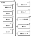
図2は、本実施形態に係るクレーン10の油圧駆動装置50(ウインチ駆動装置)の油圧回路図である。図3は、本実施形態に係るクレーン10の制御部70の電気的なブロック図である。
FIG. 2 is a hydraulic circuit diagram of the hydraulic drive device 50 (winch drive device) of the
クレーン10は、油圧駆動装置50を備える。油圧駆動装置50は、主巻用ウインチ30を駆動するシステムであって、セカンダリーコントロールシステム(Secondary Control System 以下、SCSという)が適用されている。なお、本実施形態では、油圧駆動装置50が主巻用ウインチ30を駆動する態様にて説明するが、油圧駆動装置50は、補巻用ウインチ31を駆動する態様でもよい。図2を参照して、油圧駆動装置50は、油圧ポンプ51と、油圧モータ52と、第1メイン油路50A(第1油路)と、第2メイン油路50B(第2油路)と、アキュムレータ53と、連通切換部50S(遮断機構)と、モータ容量制御部50Tと、リリーフ弁57と、を備える。
The
油圧ポンプ51は、不図示のエンジン(駆動源)の駆動力をうけ、油圧モータ52に供給されるべき作動油をタンクから吸い込んで吐出する。本実施形態に係る油圧ポンプ52は、可変容量式の油圧ポンプからなり、当該油圧ポンプ51に含まれる図示されないレギュレータへのポンプ指令信号の入力により油圧ポンプ51の容量(押しのけ容積)が変化し、これにより油圧ポンプ51から吐出される作動油の流量であるポンプ吐出流量が変化する。なお、上記のポンプ指令信号は、後記の駆動制御部701(図3)から出力部705を通じて出力される。
The
油圧モータ52は、主巻用ウインチ30に接続される両傾転可変容量式の油圧モータである。油圧モータ52は、油圧ポンプ51から吐出される作動油を受け入れるとともに作動油を吐出することで、主巻用ウインチ30を軸回りに前記第1回転方向および前記第2回転方向に回転させる。本実施形態では、油圧モータ52は斜板式モータであって、当該油圧モータ52の容量を変化させるように移動可能な不図示の斜板(可動部、容量可変機構)を有する。当該斜板の傾転は、モータ容量制御部50Tによって制御される。油圧モータ52は、モータ第1ポート52Aと、モータ第2ポート52Bと、を有する。
The
第1メイン油路50Aは、油圧ポンプ51と油圧モータ52のモータ第1ポート52Aとを連通する。
The first
第2メイン油路50Bは、油圧モータ52のモータ第2ポート52Bとタンクとを連通する。
The second
アキュムレータ53は、第1メイン油路50Aのうち後記の第1方向制御弁55と油圧モータ52との間の部分に接続されている。アキュムレータ53は、モータ第1ポート52Aから吐出された作動油のエネルギーを蓄圧する。
The
連通切換部50Sは、第1メイン油路50Aおよび第2メイン油路50Bにおける作動油の流通と当該流通の遮断とを切り換える機能を有する。特に、本実施形態では、連通切換部50Sは、モータ容量制御部50Tに入力される指令信号が特定の異常状態(天絡または地絡)になった場合に、第1メイン油路50Aおよび第2メイン油路50Bにおける作動油の流通を遮断する。連通切換部50Sは、電磁方向制御弁54(切換部)と、第1方向制御弁55と、第2方向制御弁56と、を有する。なお、連通切換部50Sは、本発明の遮断機構の一部を構成する。
The
第1方向制御弁55は、パイロット操作式の方向制御弁からなり、図2に示すように、第1パイロット油路50Cに接続された1つのパイロットポートを有する。第1方向制御弁55は、パイロットポートにパイロット圧が供給されない場合には、ばね部材の付勢力によって図2の遮断位置に保たれる。この結果、第1メイン油路50Aにおける作動油の流通が遮断される。一方、第1方向制御弁55は、第1パイロット油路50Cを通じてパイロットポートにパイロット圧を受け入れると連通位置(流通位置)に切換えられる。この結果、第1メイン油路50Aにおける作動油の流通が可能とされる。
The first
同様に、第2方向制御弁56は、パイロット操作式の方向制御弁からなり、図2に示すように、第2パイロット油路50Dに接続された1つのパイロットポートを有する。第2方向制御弁56は、パイロットポートにパイロット圧が供給されない場合には、ばね部材の付勢力によって図2の遮断位置に保たれる。この結果、第1メイン油路50Aにおける作動油の流通が遮断される。一方、第2方向制御弁56は、第2パイロット油路50Dを通じてパイロットポートにパイロット圧を受け入れると連通位置(流通位置)に切換えられる。この結果、第2メイン油路50Bにおける作動油の流通が可能とされる。なお、第1方向制御弁55および第2方向制御弁56における作動油の圧力損失は、従来のコントロールバルブ(流量制御弁)よりも小さい。
Similarly, the 2nd
電磁方向制御弁54は、図2に示すように、1つのソレノイドを有する。当該ソレノイドが、後記の制御部70の出力部705が出力する指令信号を受けると、電磁方向制御弁54は、第1メイン油路50Aと第1パイロット油路50Cおよび第2パイロット油路50Dとを連通する連通位置に切り換えられる。一方、後記の判定部703によって前記指令信号が異常状態となったと判定されると、出力部705が出力する上記の指令信号がソレノイドに入力されない。この場合、電磁方向制御弁54は、第1メイン油路50Aと第1パイロット油路50Cおよび第2パイロット油路50Dとの連通を遮断する。なお、電磁方向制御弁54は、第1方向制御弁55および第2方向制御弁56における作動油の流通および遮断を同期して切り換える。
The electromagnetic
モータ容量制御部50Tは、油圧モータ52の容量(傾転)を制御する機能を有する。この際、モータ容量制御部50Tは、後記の出力部705が出力する指令信号が正常状態の場合、当該指令信号を受け入れ当該指令信号に応じて油圧モータ52の容量を制御する。また、モータ容量制御部50Tは、出力部705が出力する指令信号が特定の異常状態になることに連動して、油圧モータ52の容量を非常用容量に設定する。当該非常用容量とは、ゼロよりも大きくかつ主巻用ウインチ30に対して吊り荷を巻き上げる回転方向(第1回転方向)にトルクを発生させることが可能な容量である。
The motor
図2を参照して、モータ容量制御部50Tは、容量制御シリンダ60(第1容量制御シリンダ)と、付勢ばね64(非常用切換機構、第1付勢部材)と、電磁方向制御弁65(第1電磁方向制御弁)と、を有する。
Referring to FIG. 2, the motor
容量制御シリンダ60は、油圧モータ52の斜板(可動部)に接続され、作動油を受け入れるとともに作動油を吐出することで当該斜板を駆動する。容量制御シリンダ60は、シリンダ本体61と、ピストン62と、ピストンロッド63と、を有する。シリンダ本体61は円筒形状を備える。ピストン62は、シリンダ本体61内を移動可能なようにシリンダ本体61に支持されている。ピストンロッド63の一端は油圧モータ52の斜板に接続され、ピストンロッド63の他端はピストン62に接続されている。そして、ピストン62によって、シリンダ本体61内にロッド側油室61Aおよびヘッド側油室61Bがそれぞれ画定されている。ロッド側油室61Aは、第1サブ油路60Aを通じて、油圧ポンプ51またはタンクに連通される。また、ヘッド側油室61Bは、第2サブ油路60Bを通じて、油圧ポンプ51またはタンクに連通される。
The
付勢ばね64は、前記指令信号が異常状態になることに連動して、油圧モータ52の容量を前記非常用容量に設定する切換位置に電磁方向制御弁65を強制的に切り換える機能を有する。本実施形態では、付勢ばね64は、油圧モータ52の容量が前述の非常用容量となる位置に油圧モータ52の斜板が移動するようにピストン62を付勢する。
The biasing spring 64 has a function of forcibly switching the electromagnetic
電磁方向制御弁65は、4ポート流量制御弁(電磁比例弁)である。電磁方向制御弁65は、制御部70の出力部705が出力する指令信号を受け入れ、当該指令信号に応じて容量制御シリンダ60に対する作動油の給排を切り換える。詳しくは、電磁方向制御弁65は、容量制御シリンダ60のロッド側油室61Aおよびヘッド側油室61Bに対する作動油の給排を切り換えることでピストン62を移動させる。電磁方向制御弁65は、内部に移動可能な不図示のスプールを備えている。当該スプールは、第1切換位置65Aと、第2切換位置65Bと、第3切換位置65Cと、第4切換位置65D(非常用連通位置)との間で移動することが可能であり、その移動量も調整可能である。
The electromagnetic
主フック34Aに吊り荷が吊り下げられた状態で、電磁方向制御弁65が第1切換位置65Aに設定されると、容量制御シリンダ60のロッド側油室61Aが電磁方向制御弁65を介して油圧ポンプ51に連通するとともに、ヘッド側油室61Bがタンクに連通する。この結果、油圧ポンプ51が吐出する作動油が第1サブ油路60Aからロッド側油室61Aに流入し、ヘッド側油室61Bの作動油が第2サブ油路60Bを通じてタンクに排出される。そして、油圧モータ52の斜板が正転側に移動し、主巻用ウインチ30が第1回転方向に回転可能とされる。すなわち、吊り荷の巻き上げが可能となる。また、主フック34Aに吊り荷が吊り下げられた状態で、電磁方向制御弁65が第2切換位置65Bに設定されると、所定の圧力損失を発生しながら、ロッド側油室61Aとヘッド側油室61Bとが連通する。すなわち、電磁方向制御弁65のスプールが中立位置に配置される。また、電磁方向制御弁65が第3切換位置65Cに設定されると、容量制御シリンダ60のロッド側油室61Aがタンクに連通し、ヘッド側油室61Bが電磁方向制御弁65を介して油圧ポンプ51に連通する。この結果、油圧ポンプ51が吐出する作動油が第2サブ油路60Bからヘッド側油室61Bに流入し、ロッド側油室61Aの作動油が第1サブ油路60Aを通じてタンクに排出される。そして、油圧モータ52の斜板が逆転側に移動し、主巻用ウインチ30が第2回転方向に回転可能とされる。すなわち、吊り荷の巻き下げが可能となる。
When the electromagnetic
更に、電磁方向制御弁65は、前記指令信号が地絡状態になることに連動して、ロッド側油室61Aおよびヘッド側油室61Bを互いに連通させる第4切換位置65D(非常用連通位置)に切り換わる。この際、付勢ばね64は、前記指令信号が地絡状態になることに連動して、油圧モータ52の容量が前記非常用容量となる位置に斜板が移動するようにピストン62を付勢する。また、電磁方向制御弁65は、前記指令信号が天絡状態になることに連動して、前述の第1切換位置65A(非常用給排位置)に切り換わる。当該第1切換位置65Aでは、電磁方向制御弁65は、付勢ばね64がピストン62を付勢する方向と同じ方向にピストン62を移動させるように、ロッド側油室61Aおよびヘッド側油室61Bに対する作動油の給排を行う。この際、電磁方向制御弁65には最大電流が流入され、付勢ばね64の付勢力に抗して、第1切換位置65A(非常用給排位置)に切り換わる。
Further, the electromagnetic
更に、油圧駆動装置50は、制御部70と、操作レバー71(被操作部)と、表示部72と、回転速度センサ73(特性値検出部)と、を有する(図3)。
Further, the
制御部70は、クレーン10の動作を統括的に制御するもので、制御信号の送受先として、油圧ポンプ51、操作レバー71、モータ容量制御部50T、表示部72および回転速度センサ73などに電気的に接続されている。なお、制御部70は、クレーン10に備えられたその他のユニットにも電気的に接続されている。
The
制御部70は、CPU(Central Processing Unit)、制御プログラムを記憶するROM(Read Only Memory)、CPUの作業領域として使用されるRAM(Random Access Memory)等から構成され、CPUが前記制御プログラムを実行することにより、駆動制御部701、演算部702、判定部703、記憶部704および出力部705を機能的に有するよう動作する。
The
駆動制御部701は、油圧ポンプ51を駆動制御する。演算部702は、油圧駆動装置50の動作において必要な特性値を演算する。判定部703は、回転速度センサ73が検出する油圧モータ52の角速度と記憶部704が出力する角速度の目標値とを比較することで、モータ容量制御部50Tに入力される指令信号が正常状態であるか前記特定の異常状態であるかを判定する。なお、判定部703は、本発明の遮断機構の一部を構成する。記憶部704は、油圧駆動装置50の制御において必要な各特性値を予め記憶しているとともに、当該特性値を出力可能である。出力部705は、通常のクレーン10の作業時に、操作レバー71が受ける操作量に応じた制御電流(電流値)からなる指令信号をモータ容量制御部50Tに対して出力する。また、出力部705は、判定部703の判定結果に応じて、電磁方向制御弁54に対して第1メイン油路50Aおよび第2メイン油路50Bを遮断するための指令信号を出力する。
The
操作レバー71は、吊り荷の巻き上げおよび巻き下げのための操作を受ける。操作レバー71は、クレーン10のキャブ(運転室)内に配置されている。操作レバー71は、吊り荷の巻き上げを指示するための巻き上げ操作領域と、吊り荷の巻き下げを指示するための巻き下げ操作領域と、両操作領域の間の中立操作位置との間で切換可能とされている。
The
なお、クレーン10は、不図示のネガティブブレーキを更に備えている。当該ネガティブブレーキは、主巻用ウインチ30の回転を強制的に阻止する機能を有する。ネガティブブレーキは、主巻用ウインチ30の回転軸またはドラム面に機械的に当接し、主巻用ウインチ30の回転を規制する。本実施形態では、操作レバー71が中立操作位置に配置されると、ネガティブブレーキによって主巻用ウインチ30の回転が規制される。
The
表示部72は、クレーン10のキャブ内に配置された液晶モニタであり、クレーン10の各種操作情報に加え、油圧駆動装置50の各種ステータス情報が表示される。
The
回転速度センサ73は、油圧モータ52の回転速度(角速度)を検出する。また、回転速度センサ73は、油圧モータ52の回転方向(第1方向、第2方向)を検出する。回転速度センサ73が検出する油圧モータ52の回転速度は、本発明に係る油圧モータの作動特性値に相当する。
The
リリーフ弁57(図2)は、第1メイン油路50Aの圧力が所定の圧力を超えないように作動する。この結果、第1方向制御弁55が第1メイン油路50Aを開通している状態において、リリーフ弁57は第1メイン油路50Aの圧力を一定に保つ機能を有する。なお、第1メイン油路50Aに不図示の圧力センサが備えられ、当該圧力センサの検出結果に応じて、油圧ポンプ51の容量が調整されることで、第1メイン油路50Aの圧力が一定に保たれてもよい。
The relief valve 57 (FIG. 2) operates so that the pressure in the first
前述のようにセカンダリーコントロールシステムでは、油圧ポンプ51から延びる第1メイン油路50Aが常に高圧側であり、タンクに接続される第2メイン油路50Bが常に低圧側となる。そして、油圧モータ52が吐出する作動油の圧力が一定に維持され、油圧モータ52の容量(傾転)が調整されることで、主巻用ウインチ30による吊り荷の巻き上げ、巻き下げが実行される。したがって、従来のウインチシステムのように、油圧ポンプと油圧モータとの間に、コントロールバルブが必要とされず、作動油の圧力損失が低減される。この結果、従来よりも省エネ効果が実現される。
As described above, in the secondary control system, the first
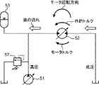
図4乃至図7は、本実施形態に係るセカンダリーコントロールシステムが適用されたクレーン10において、吊り荷の巻き上げ、巻き下げ動作における作動油の流れおよび油圧モータ52の回転方向をそれぞれ説明する模式図である。通常、油圧モータ52には、吊り荷の負荷により生じるトルク(負荷トルク)と、摩擦等の機械的な損失トルク(摩擦トルク)が生じる。図4乃至図7では、負荷トルクおよび摩擦トルクを足し合わせたものを外的トルクとして表記している。負荷トルクは吊り荷の質量に基づいて重力によって発生するため、油圧モータ52の回転方向に依らず常に巻き下げ回転方向のトルクとして作用する。一方、摩擦トルクは油圧モータ52の回転方向とは逆方向に発生するため、油圧モータ52の回転方向によってその作用する方向が逆転する。したがって、吊り荷の巻き上げ時には、摩擦トルクおよび負荷トルクは互いに同じ回転方向に作用する。このため、油圧モータ52は、(負荷トルクの絶対値+摩擦トルクの絶対値)以上のトルクを出す必要がある。一方、吊り荷の巻き下げ時には、摩擦トルクは負荷トルクとは逆方向に作用するため、負荷トルクの一部と摩擦トルクの一部が互いに相殺される。このため、油圧モータ52に要求されるトルクは、巻き上げ時と比較して相対的に小さくなる。
4 to 7 are schematic diagrams for explaining the flow of hydraulic oil and the rotation direction of the
図4は、主巻ロープ32に接続された主フック34A(図1)に吊り荷が掛けられた有負荷状態であって、吊り荷の巻き上げが行われる状態を示している。この場合、モータ容量制御部50Tによって油圧モータ52の傾転が所定の値に設定されると、作動油は、第1メイン油路50Aおよび第2メイン油路50Bを高圧側から低圧側に流れる。また、油圧モータ52のモータトルクが外的トルク(吊り荷の負荷によって主巻用ウインチ30に生じる負荷トルク+摩擦トルク)よりも大きいため、油圧モータ52は、吊り荷の負荷方向(負荷トルクの方向)とは逆方向(第1回転方向)に回転する。この結果、吊り荷の巻き上げが行われる。
FIG. 4 shows a loaded state in which a suspended load is hung on the main hook 34 </ b> A (FIG. 1) connected to the main winding
また、図5は、主巻ロープ32に接続された主フック34A(図1)に吊り荷が掛けられていない無負荷状態であって、主フック34Aの巻き上げが行われる状態を示している。作動油は、第1メイン油路50Aおよび第2メイン油路50Bを高圧側から低圧側に流れる。また、この場合も、油圧モータ52のモータトルクが外的トルク(主フック34Aの負荷によって主巻用ウインチ30に生じる負荷トルク+摩擦トルク)よりも大きいため、油圧モータ52は、主フック34Aの負荷方向(負荷トルクの方向)とは逆方向(第1回転方向)に回転する。この結果、吊り荷が掛けられていない主フック34Aの巻き上げが行われる。
FIG. 5 shows a state in which the
また、図6は、主巻ロープ32に接続された主フック34A(図1)に吊り荷が掛けられた有負荷状態であって、吊り荷の巻き下げが行われる状態を示している。この場合、モータ容量制御部50Tによって油圧モータ52の傾転が逆転側に設定されると、作動油は、第1メイン油路50Aおよび第2メイン油路50Bを部分的に低圧側から高圧側に流れる。この際、一部の作動油はアキュムレータ53に回収される。また、油圧モータ52のモータトルクは外的トルク(吊り荷の負荷によって生じる負荷トルク−摩擦トルク)よりも小さいため、油圧モータ52は、吊り荷の負荷方向(負荷トルクの方向、第2回転方向)に回転する。この結果、吊り荷の巻き下げが行われる。
FIG. 6 shows a loaded state in which a suspended load is hung on the main hook 34 </ b> A (FIG. 1) connected to the main winding
更に、図7は、主巻ロープ32に接続された主フック34A(図1)に吊り荷が掛けられていない無負荷状態であって、主フック34Aの巻き下げが行われる状態を示している。この場合、作動油は、第1メイン油路50Aおよび第2メイン油路50Bを高圧側から低圧側に流れる。また、油圧モータ52のモータトルクが外的トルク(主フック34Aの負荷によって主巻用ウインチ30に生じる負荷トルク−摩擦トルク)よりも大きいため、油圧モータ52は、吊り荷の負荷方向(負荷トルクの方向、第2回転方向、外的トルクの方向および摩擦トルクの方向とは逆方向)に回転する。この結果、主フック34Aの巻き下げが行われる。なお、図7の場合には、摩擦トルクが負荷トルクよりも大きくなるため、図6と比較して、外的トルクが作用する方向が逆になっている。
Further, FIG. 7 shows a state in which the
このように、セカンダリーコントロールシステムを適用したウインチシステムでは、吊荷(主フック34A)が落下(下降)する場合の油圧モータ52のメータイン側流路およびメータアウト側流路(作動油の流れる向き)が反転する場合がある(図6、図7)。また、図2に示すように、油圧駆動装置50のうち油圧モータ52の周囲の油路では、油圧ポンプ51に接続される第1メイン油路50Aが常に高圧であり、タンクに接続される第2メイン油路50Bが常に低圧に維持される。また、油圧モータ52の容量制御機構における故障の仕方(制御電流の天絡、地絡等)によって、故障時の油圧モータ52の容量が異なる。したがって、従来のように外部パイロット式のカウンタバランス弁を第1メイン油路50Aおよび第2メイン油路50Bのうちの一方の油路に配置したとしても、クレーン10の使用条件によっては、油圧モータ52の制御が不能となった場合に吊り荷の落下を防止することができない。更に、油圧モータ52は両傾転可変容量式であるために、故障時に油圧モータ52の容量がゼロ容量となる可能性がある。この場合、従来のカウンタバランス弁のような機構によって油圧モータ52のメータアウト側流路が絞られたとしても、油圧モータ52にはトルク(ブレーキトルク)が発生しないため、結果的に主巻用ウインチ30を停止させることができない。このように、セカンダリーコントロールシステムを適用したウインチシステムは、従来のウインチシステムとは異なる特性を有するために、故障時の吊り荷の落下防止策が必要とされる。
Thus, in the winch system to which the secondary control system is applied, the meter-in side channel and the meter-out side channel (the direction in which hydraulic oil flows) of the
上記のような課題を解決するために、本実施形態では、モータ容量制御部50Tおよび連通切換部50Sが、非常時用制御を実行する。図2を参照して、出力部705(図3)から出力され電磁方向制御弁65に入力される容量制御用の指令信号(電流値)が、異常によりゼロとなってしまった場合(地絡)、電磁方向制御弁65は付勢ばね65Eによって図2の第4切換位置65D(初期位置)に戻される。第4切換位置65Dでは、容量制御シリンダ60のロッド側油室61Aおよびヘッド側油室61Bが共にタンクに連通される。このため、ロッド側油室61Aおよびヘッド側油室61Bの圧力は等しくなる(同圧)。この際、ピストンロッド63は、付勢ばね64の付勢力によって、油圧モータ52の斜板を正転側の非常用位置に移動させる。斜板が当該非常用位置に移動されると、油圧モータ52の容量(押しのけ容積)は、ゼロよりも大きく、主巻用ウインチ30に対して吊り荷を持ち上げる方向(第1回転方向)にトルクを発生させる非常用容量となる。これらの動作は、指令信号の電流値の地絡に連動して機械的に行われる。
In order to solve the above problems, in the present embodiment, the motor
一方、回転速度センサ73(図3)は、操作レバー71が操作されると、油圧モータ52の回転速度(角速度)を検出する。また、記憶部704は、操作レバー71が受ける操作量に応じた油圧モータ52の角速度の目標値を出力する。そして、判定部703は、回転速度センサ73が検出する油圧モータ52の角速度と記憶部704が出力する角速度の目標値とを比較し、両者の差が所定の閾値を超えている場合に、前記指令信号が特定の異常状態となったと判定する。なお、油圧モータ52の容量が前述の非常用容量に設定されると、非常用容量は操作レバー71の操作量に応じた容量と大きく異なるため、上記のように異常状態と判定される。この結果、出力部705が、電磁方向制御弁54に対して非常用の指令信号を出力し、電磁方向制御弁54が連通位置に設定される。そして、第1パイロット油路50Cおよび第2パイロット油路50Dを通じて、第1方向制御弁55および第2方向制御弁56のパイロットポートにパイロット圧が供給されると、第1方向制御弁55および第2方向制御弁56が遮断位置に切り換わる。この結果、第1メイン油路50Aおよび第2メイン油路50Bが、それぞれ遮断される。
On the other hand, the rotation speed sensor 73 (FIG. 3) detects the rotation speed (angular speed) of the
このように、モータ容量制御部50Tの電磁方向制御弁65に入力される指令信号の電流値が地絡すると、油圧モータ52の容量がゼロではない非常用容量に設定されるとともに、第1メイン油路50Aおよび第2メイン油路50Bにおける作動油の流通が遮断される。この結果、油圧モータ52は、遮断された第1メイン油路50Aおよび第2メイン油路50Bの油圧モータ52側に残存する作動油を押しのけながら吊り荷を巻き上げる回転方向にトルクを発生し、やがて油圧モータ52にブレーキトルクが付与さ油圧モータ52の回転が停止する。このため、主巻用ウインチ30が油圧的に吊り荷を保持することが可能となり、吊り荷の落下を速やかに阻止することできる。
Thus, when the current value of the command signal input to the electromagnetic
一方、モータ容量制御部50Tの電磁方向制御弁65に入力される指令信号が天絡する(最大値に振れたままとなる)と、電磁方向制御弁65は、強制的に図2の第1切換位置65Aに設定される。第1切換位置65Aでは、主巻用ウインチ30に対して吊り荷の持ち上げ方向にトルクを発生させるような容量に油圧モータ52の容量が増大される。すなわち、油圧モータ52の容量がゼロではない非常用容量に設定される。また、当該非常用容量は操作レバー71の操作量に応じた容量と大きく異なるため、上記のように判定部703は指令信号が異常状態であると判定する。この結果、第1メイン油路50Aおよび第2メイン油路50Bにおける作動油の流通が同様に遮断される。したがって、地絡の場合と同様に、油圧モータ52にブレーキトルクが付与され、速やかに吊り荷の落下を阻止することができる。
On the other hand, when the command signal input to the electromagnetic
図8は、本実施形態に係るクレーン10において、有負荷巻き下げ作業時に、油圧モータ52の容量を制御する指令信号に異常が発生した場合の油圧駆動装置50の挙動を示すグラフ群である。また、図9は、本実施形態に係るクレーン10と比較される他の作業装置において、有負荷巻き下げ作業時に、可変容量式モータの容量を制御する指令信号に異常が発生した場合の油圧駆動装置の挙動を示すグラフ群である。
FIG. 8 is a group of graphs showing the behavior of the
図8を参照して、時刻0から作業者によって操作レバー71が操作され、吊り荷の巻き下げ作業が行われる。本実施形態では、時刻T1において指令信号に故障が発生し、当該指令信号の電流が地絡すると、前述のように、油圧モータ52の容量が速やかに非常用容量に設定される(図8のモータ容量のグラフの「故障時(制御ケース)」参照)。これに遅れて、時刻T2には、第1方向制御弁55および第2方向制御弁56が第1メイン油路50Aおよび第2メイン油路50Bを遮断する(図8の方向制御弁のグラフ参照)。なお、作業者は、指令信号の故障に気づいていないため、引き続き、操作レバー71を操作している(図8のレバーのグラフ参照)。第1メイン油路50Aおよび第2メイン油路50Bが遮断され、油圧モータ52の容量が非常用容量に設定されることで、油圧モータ52にブレーキトルクが加わり、モータ速度が油圧的に減速され、やがてゼロとなる(図8のモータ速度のグラフ参照)。やがて、作業者が、油圧モータ52の減速および主巻用ウインチ30の停止に気づいて又は通常の作業手順に従って、時刻T3に操作レバー71を操作中立領域に戻し始める。そして、時刻T4に操作レバー71が操作中立領域に至ると、不図示のネガティブブレーキがONされ、主巻用ウインチ30の回転が機械的に阻止される。このように、本実施形態では、作業者によって操作レバー71が操作中立領域に戻されるよりも先に、油圧的に油圧モータ52にブレーキを掛けることができる。したがって、指令信号の故障が発生した場合でも、速やかに吊り荷の落下を防止することができる。なお、図8では比較のために、モータ容量制御用の指令信号に異常が発生したままの場合(非制御ケース)と、モータ容量制御用の指令信号が正常の場合(通常時)のグラフも示している。
Referring to FIG. 8, the
一方、図9を参照して、本実施形態に係る吊り荷落下防止の機構を備えていない油圧駆動装置における有負荷巻き下げ時の挙動について説明する。時刻t1において指令信号に故障が発生し、当該指令信号の電流が地絡する。作業者は、指令信号の故障に気づかないまま、時刻t2に操作レバー71を操作中立領域に戻し始める。指令信号に故障が発生していない場合には、この操作によって、油圧モータの容量が増大されるため、油圧モータの回転が減速する(図9のモータ容量、モータ速度のグラフの破線参照)。しかしながら、指令信号に故障が発生している場合には、モータ容量が増大されないため、操作レバーが完全に操作中立領域に至る時刻t3に、機械的なネガティブブレーキによって主巻用ウインチ30の回転が停止する。すなわち、時刻t2から時刻t3までの間のうち故障時の実線と通常時の破線とで囲まれる三角形の面積(積分値)の分だけ、吊り荷が余分に落下する。
On the other hand, with reference to FIG. 9, the behavior at the time of unloading with a load in the hydraulic drive apparatus that does not include the hanging load fall prevention mechanism according to the present embodiment will be described. At time t1, a failure occurs in the command signal, and the current of the command signal is grounded. The operator starts returning the
以上のように、本実施形態では、セカンダリーコントロールシステムによって駆動されるウインチドラムを含む作業機械において、両傾転可変容量式の油圧モータの容量を制御する指令信号に異常が発生すると、油圧モータの容量が非常用容量に設定される。当該非常用容量は、ゼロよりも大きくかつウインチドラムに対して吊り荷を巻き上げる回転方向にトルクを発生させる。また、遮断機構は、第1油路および第2油路における作動油の流通をそれぞれ遮断する。この結果、油圧モータは、遮断された第1油路および第2油路に残存する作動油を押しのけながら吊り荷を巻き上げる回転方向にトルクを発生し、やがて油圧モータの回転が停止する。このため、ウインチドラムが油圧的に吊り荷を保持することが可能となり、吊り荷の落下を速やかに阻止することできる。 As described above, in the present embodiment, when an abnormality occurs in the command signal that controls the displacement of the bi-tilt variable displacement hydraulic motor in the work machine including the winch drum driven by the secondary control system, the hydraulic motor The capacity is set to the emergency capacity. The emergency capacity is greater than zero and generates torque in the rotational direction that winds up the suspended load on the winch drum. Further, the blocking mechanism blocks the flow of hydraulic oil in the first oil passage and the second oil passage, respectively. As a result, the hydraulic motor generates torque in the rotational direction in which the suspended load is wound up while pushing away the hydraulic oil remaining in the blocked first oil passage and second oil passage, and eventually the rotation of the hydraulic motor stops. For this reason, the winch drum can hydraulically hold the suspended load, and the suspended load can be quickly prevented from falling.
このように、セカンダリーコントロールシステムをウインチシステムに適用した場合、故障などの非常停止前の油圧モータ52の回転方向は、吊り荷の質量と故障の種別(例えば天絡と地絡の違い)によって異なる。特に、故障によって吊り荷の落下が発生しうる場面では、油圧モータ52は故障時に巻き下げ方向に回転している。本実施形態では、油圧モータ52に非常用容量を持たせると共に2つの油路を遮断することで、吊り荷を巻き上げる回転方向にトルクが発生し、油圧モータ52の回転数が低下し最終的に停止する。
As described above, when the secondary control system is applied to the winch system, the rotation direction of the
また、本実施形態では、油圧モータの作動特性値が操作レバーの操作量に応じた目標値と乖離することを利用して、指令信号に異常が発生したことが判定されるとともに、第1油路および第2油路を遮断することができる。 In the present embodiment, it is determined that an abnormality has occurred in the command signal by utilizing the fact that the operating characteristic value of the hydraulic motor deviates from the target value corresponding to the operation amount of the operation lever, and the first oil The passage and the second oil passage can be blocked.
更に、本実施形態では、第1油路および第2油路にそれぞれ設けられた第1方向制御弁および第2方向制御弁によって、各油路における作動油の流通と遮断とを容易に切り換えることができる。 Further, in the present embodiment, the flow and shut-off of the hydraulic oil in each oil passage are easily switched by the first direction control valve and the second direction control valve provided in the first oil passage and the second oil passage, respectively. Can do.
また、本実施形態では、油圧モータの容量を制御する指令信号が地絡した場合、第1電磁方向制御弁が非常用連通位置に切り換わることで、油圧的にピストンを移動させる駆動力が失われる。そして、ピストンに接続された可動部は、付勢部材の付勢力によって、油圧モータの容量を非常用容量に設定する位置に移動する。このため、指令信号が地絡した場合でも、油圧モータの容量を確実に非常用容量に設定することができる。また、油圧モータの容量を制御する指令信号が天絡した場合、第1電磁方向制御弁が非常用給排位置に切り換わることで、ピストンに接続された可動部を油圧的に移動させることができる。移動された可動部は、吊り荷を巻き上げることが可能な容量に油圧モータの容量を設定する。このため、指令信号が天絡した場合でも、吊り荷の落下を阻止することができる。 In this embodiment, when the command signal for controlling the capacity of the hydraulic motor is grounded, the first electromagnetic directional control valve is switched to the emergency communication position, so that the driving force for hydraulically moving the piston is lost. Is called. The movable portion connected to the piston moves to a position where the capacity of the hydraulic motor is set to the emergency capacity by the urging force of the urging member. For this reason, even when the command signal has a ground fault, the capacity of the hydraulic motor can be reliably set to the emergency capacity. In addition, when the command signal for controlling the capacity of the hydraulic motor has a power fault, the movable part connected to the piston can be hydraulically moved by switching the first electromagnetic direction control valve to the emergency supply / discharge position. it can. The moved movable part sets the capacity of the hydraulic motor to a capacity capable of winding up the suspended load. For this reason, even if the command signal has a power fault, the suspended load can be prevented from falling.
次に、本発明の第2実施形態について説明する。なお、本実施形態では、先の実施形態と比較して、モータ容量制御部の構造において相違するため、当該相違点を中心に説明し、共通する点の説明を省略する。図10は、本実施形態に係るクレーンの油圧駆動装置80(ウインチ駆動装置)の油圧回路図である。 Next, a second embodiment of the present invention will be described. In addition, in this embodiment, since it differs in the structure of a motor capacity | capacitance control part compared with previous embodiment, it demonstrates centering on the said difference and description of a common point is abbreviate | omitted. FIG. 10 is a hydraulic circuit diagram of the crane hydraulic drive device 80 (winch drive device) according to the present embodiment.
油圧駆動装置80は、先の実施形態に係る油圧駆動装置50のモータ容量制御部50Tの代わりにモータ容量制御部80Tを備える。モータ容量制御部80Tは、容量制御シリンダ90(第2容量制御シリンダ)と、電磁方向制御弁95(第2電磁方向制御弁)と、を有する。
The
容量制御シリンダ90は、油圧モータ52の斜板(可動部)に接続され当該斜板を駆動する。容量制御シリンダ90は、シリンダ本体91と、ピストン92と、ピストンロッド93と、を有する。シリンダ本体91は円筒形状を備える。ピストン92は、シリンダ本体91内を移動可能なようにシリンダ本体91に支持されている。ピストンロッド93の一端は油圧モータ52の斜板に接続され、ピストンロッド93の他端はピストン92に接続されている。そして、ピストン92によって、シリンダ本体91内にロッド側油室91Aおよびヘッド側油室91Bがそれぞれ画定されている。ロッド側油室91Aは、第1サブ油路90Aを通じて、油圧ポンプ51またはタンクに連通される。また、ヘッド側油室91Bは、第2サブ油路90Bを通じて、油圧ポンプ51またはタンクに連通される。
The
電磁方向制御弁95は、3ポート流量制御弁(電磁比例弁)である。電磁方向制御弁95は、制御信号回路80TAを通じて、制御部70に電気的に接続されている。電磁方向制御弁95は、制御部70の出力部705が出力する指令信号を受け入れ、当該指令信号に応じて容量制御シリンダ90のロッド側油室91Aおよびヘッド側油室91Bに対する作動油の給排を切り換えることでピストン92を移動させる。電磁方向制御弁95は、内部に移動可能な不図示のスプールを備えている。当該スプールは、第1切換位置95A(非常用給排位置)と、第2切換位置95Bと、第3切換位置95Cとの間で移動することが可能であり、その移動量も調整可能である。
The electromagnetic
電磁方向制御弁95が第1切換位置95Aに設定されると、容量制御シリンダ90のロッド側油室91Aが第1サブ油路90Aを通じて油圧ポンプ51に連通するとともに、ヘッド側油室91Bが第2サブ油路90Bを通じてタンクに連通する。この時、ピストンロッド93に接続された油圧モータ52の斜板は正転側に配置される。また、電磁方向制御弁95が第2切換位置95Bに設定されると、所定の圧力損失を発生しながら、ロッド側油室91Aとヘッド側油室91Bとが連通する。すなわち、電磁方向制御弁95のスプールが中立位置に配置されるとともに、油圧モータ52の斜板がゼロ傾転位置に配置される。また、電磁方向制御弁95が第3切換位置95Cに設定されると、容量制御シリンダ90のロッド側油室91Aがタンクに連通し、ヘッド側油室91Bが電磁方向制御弁95を介して油圧ポンプ91に連通する。この時、ピストンロッド93に接続された油圧モータ52の斜板は逆転側に配置される。
When the electromagnetic
そして、本実施形態では、電磁方向制御弁95に対する指令信号が天絡および地絡のいずれの異常状態となった場合でも、電磁方向制御弁95は、指令信号の異常に連動して第1切換位置95Aに切り換わる。第1切換位置95Aでは、電磁方向制御弁95は、油圧モータ52の容量が非常用容量となる位置に斜板が移動するように、ロッド側油室91Aおよびヘッド側油室91Bに対する作動油の給排を行う。この際、付勢ばね95D(非常用切換機構、第2付勢部材)が、前記指令信号が地絡状態または天絡状態になることに連動して、電磁方向制御弁95が第1切換位置95Aに切り換わるように電磁方向制御弁95の不図示のスプールを付勢する。
In this embodiment, even when the command signal for the electromagnetic
このような構成においても、油圧モータ52の容量を制御する指令信号が地絡または天絡した場合、電磁方向制御弁95が非常用給排位置に切り換わることで、ピストンロッド93に接続された油圧モータ52の斜板を油圧的に移動させることができる。移動された斜板は、吊り荷を巻き上げることが可能な非常用容量に油圧モータ52の容量を設定する。このため、指令信号が地絡または天絡した場合でも、吊り荷の落下を阻止することができる。
Even in such a configuration, when the command signal for controlling the capacity of the
以上、本発明の各実施形態に係る作業機械(クレーン10)について説明した。なお、本発明はこれらの形態に限定されるものではない。本発明に係る作業機械として、以下のような変形実施形態が可能である。 The work machine (crane 10) according to each embodiment of the present invention has been described above. The present invention is not limited to these forms. The following modified embodiments are possible as the working machine according to the present invention.
(1)上記の実施形態では、作業機械として、クレーン10を用いて説明したが、本発明はこれに限定されるものではない。本発明に係る作業機械は、その他の態様からなるものでもよい。また、油圧モータ52は、斜板を備えた両傾転可変容量式の油圧モータに限定されるものではなく、斜軸式などのその他の両傾転可変容量式の油圧モータであってもよい。
(1) In the above embodiment, the
(2)また、上記の各実施形態では、油圧駆動装置50(図2)および油圧駆動装置80(図10)が、アキュムレータ53を備える態様にて説明したが、アキュムレータ53を備えない態様でもよい。この場合、リリーフ弁57によって第1メイン油路50Aの圧力が一定に保持されればよい。
(2) Further, in each of the above embodiments, the hydraulic drive device 50 (FIG. 2) and the hydraulic drive device 80 (FIG. 10) have been described as having the
(3)また、上記の各実施形態では、油圧モータの作動特性値を検出する特性値検出部として、回転速度センサ73が油圧モータ52の回転速度(角速度)を検出する態様にて説明したが、本発明はこれに限定されるものではない。特性値検出部は、油圧モータ52の回転角度、容量などを検出するものでもよい。この場合、各特性値に対応する目標値が操作レバー71の操作量に応じて記憶部704に格納されていることが望ましい。また、複数の特性値が組み合わされることで、指令信号の異常状態が判定される態様でもよい。
(3) In each of the above embodiments, the
(4)また、上記の各実施形態では、本発明のモータ容量制御部として、容量制御シリンダ60(90)および電磁方向制御弁65(95)を備える態様で説明したが、本発明はこれに限定されるものではない。指令信号が伝達される制御信号回路50TA(80TA)に不図示の電流計が備えられ、当該電流計の検出結果に応じて、指令信号の正常状態、異常状態(地絡、天絡)が検出されてもよい。この場合も、指令信号の状態に応じて、電磁方向制御弁65(95)のポート位置が前述と同様に切換えられる。また、電磁方向制御弁65(95)とは別に他の非常用の制御弁が追加され、当該制御弁によって非常時の容量制御シリンダ60(90)に対する作動油の給排が制御されてもよい。 (4) In each of the above embodiments, the motor capacity control unit of the present invention has been described in the aspect including the capacity control cylinder 60 (90) and the electromagnetic direction control valve 65 (95). It is not limited. The control signal circuit 50TA (80TA) to which the command signal is transmitted is provided with an ammeter (not shown), and the normal state and abnormal state (ground fault, power fault) of the command signal are detected according to the detection result of the ammeter. May be. Also in this case, the port position of the electromagnetic directional control valve 65 (95) is switched in the same manner as described above according to the state of the command signal. In addition to the electromagnetic directional control valve 65 (95), another emergency control valve may be added, and the supply and discharge of hydraulic fluid to the capacity control cylinder 60 (90) in an emergency may be controlled by the control valve. .
10 クレーン
11 上部旋回体
12 下部走行体
30 主巻用ウインチ(ウインチドラム)
32 主巻ロープ(ロープ)
50 油圧駆動装置
50A 第1メイン油路(第1油路)
50B 第2メイン油路(第2油路)
50C 第1パイロット油路
50D 第2パイロット油路
50S 連通切換部(遮断機構)
50T モータ容量制御部
50TA 制御信号回路
51 油圧ポンプ
52 油圧モータ
52A モータ第1ポート
52B モータ第2ポート
53 アキュムレータ
54 電磁方向制御弁(切換部)
55 第1方向制御弁
56 第2方向制御弁
57 リリーフ弁
60 容量制御シリンダ(第1容量制御シリンダ)
60A 第1サブ油路
60B 第2サブ油路
61 シリンダ本体
61A ロッド側油室
61B ヘッド側油室
62 ピストン
63 ピストンロッド
64 付勢ばね(非常用切換機構、第1付勢部材)
65 電磁方向制御弁(第1電磁方向制御弁)
65A 第1切換位置
65B 第2切換位置
65C 第3切換位置
65D 第4切換位置
65E 付勢ばね
70 制御部
701 駆動制御部
702 演算部
703 判定部(遮断機構)
704 記憶部
705 出力部
71 操作レバー(被操作部)
72 表示部
73 回転速度センサ(特性値検出部)
10
32 Main rope (rope)
50
50B Second main oil passage (second oil passage)
50C 1st
50T Motor capacity control unit 50TA
55 1st
60A First
65 Electromagnetic direction control valve (first electromagnetic direction control valve)
65A
704
72
Claims (7)
前記ロープに接続され、軸回りに第1回転方向に回転し前記ロープを巻き取ることで前記吊り荷の巻き上げを行い、前記軸回りに前記第1回転方向とは反対の第2回転方向に回転し前記ロープを繰り出すことで前記吊り荷の巻き下げを行うウインチドラムと、
作動油を吐出する可変容量式の油圧ポンプと、
前記ウインチドラムに接続される両傾転可変容量式の油圧モータであって、前記油圧ポンプから吐出される作動油を受け入れるとともに作動油を吐出することで、前記油圧モータの容量に応じて前記ウインチドラムを前記第1回転方向および前記第2回転方向に回転させることが可能な両傾転可変容量式の油圧モータと、
前記油圧ポンプと前記油圧モータとを連通する第1油路と、
前記油圧モータとタンクとを連通する第2油路と、
前記吊り荷の巻き上げおよび巻き下げのための操作を受ける被操作部と、
前記被操作部が受ける操作量に応じた電流値からなる指令信号を出力する出力部と、
前記出力部が出力する前記指令信号が正常状態の場合、当該指令信号に応じて前記油圧モータの容量を制御するとともに、前記指令信号が特定の異常状態になることに連動して、前記油圧モータの容量をゼロよりも大きくかつ前記ウインチドラムに対して前記第1回転方向にトルクを発生させることが可能な非常用容量に設定する、モータ容量制御部と、
前記指令信号の前記正常状態および前記異常状態を判定する判定部を含み、前記指令信号が前記異常状態と判定された場合に、前記第1油路および前記第2油路における作動油の流通をそれぞれ遮断する遮断機構と、
を備える、作業機械。 A rope connected to the suspended load;
It is connected to the rope, rotates around the axis in the first rotation direction, winds up the rope, winds up the suspended load, and rotates around the axis in the second rotation direction opposite to the first rotation direction. A winch drum that unwinds the suspended load by paying out the rope;
A variable displacement hydraulic pump that discharges hydraulic oil;
A bi-tilt variable displacement type hydraulic motor connected to the winch drum, which receives hydraulic oil discharged from the hydraulic pump and discharges hydraulic oil, so that the winch is adapted according to the capacity of the hydraulic motor. A both-tilt variable displacement hydraulic motor capable of rotating a drum in the first rotation direction and the second rotation direction;
A first oil passage communicating the hydraulic pump and the hydraulic motor;
A second oil passage communicating the hydraulic motor and the tank;
An operated part that receives operations for hoisting and lowering the suspended load;
An output unit that outputs a command signal having a current value corresponding to an operation amount received by the operated unit;
When the command signal output from the output unit is in a normal state, the hydraulic motor is controlled in accordance with the command signal, and the hydraulic motor is linked with the command signal being in a specific abnormal state. A motor capacity controller that sets the capacity of the emergency capacity to be larger than zero and capable of generating torque in the first rotation direction with respect to the winch drum;
A determination unit that determines the normal state and the abnormal state of the command signal; and when the command signal is determined to be the abnormal state, the flow of hydraulic oil in the first oil passage and the second oil passage A blocking mechanism for blocking each;
A work machine comprising:
前記モータ容量制御部は、
前記油圧モータの前記可動部に接続され、作動油を受け入れるとともに作動油を吐出することで前記可動部を駆動する容量制御シリンダと、
前記出力部が出力する前記指令信号を受け入れ当該指令信号に応じて前記容量制御シリンダに対する作動油の給排を切り換える電磁方向制御弁と、
前記指令信号が前記異常状態になることに連動して、前記油圧モータの容量を前記非常用容量に設定する切換位置に前記電磁方向制御弁を強制的に切り換える非常用切換機構と、
を有する、請求項1に記載の作業機械。 The hydraulic motor has a movable part movable so as to change the capacity of the hydraulic motor,
The motor capacity controller is
A displacement control cylinder connected to the movable part of the hydraulic motor and receiving the hydraulic oil and driving the movable part by discharging the hydraulic oil;
An electromagnetic directional control valve that accepts the command signal output by the output unit and switches supply and discharge of hydraulic fluid to and from the displacement control cylinder according to the command signal;
In conjunction with the command signal becoming the abnormal state, an emergency switching mechanism for forcibly switching the electromagnetic directional control valve to a switching position for setting the capacity of the hydraulic motor to the emergency capacity;
The work machine according to claim 1, comprising:
前記電磁方向制御弁は、前記出力部が出力する前記指令信号を受け入れ当該指令信号に応じて前記第1容量制御シリンダの前記ロッド側油圧室および前記ヘッド側油圧室に対する作動油の給排を切り換えることで前記ピストンを移動させる第1電磁方向制御弁であって、前記第1電磁方向制御弁は、前記指令信号が前記異常状態としての地絡状態になることに連動して、前記ロッド側油圧室および前記ヘッド側油圧室を互いに連通させる非常用連通位置に切り換わることが可能であり、
前記非常用切換機構は、前記指令信号が前記地絡状態になることに連動して、前記油圧モータの容量が前記非常用容量となる位置に前記可動部が移動するように前記ピストンを付勢する第1付勢部材を有する、請求項2に記載の作業機械。 The displacement control cylinder is a first displacement control cylinder that is connected to the movable portion of the hydraulic motor and drives the movable portion, and the first displacement control cylinder is movable within the cylinder body and the cylinder body. A piston and a rod connected to the piston and the movable part, and the piston defines a rod-side hydraulic chamber and a head-side hydraulic chamber in the cylinder body,
The electromagnetic direction control valve receives the command signal output from the output unit, and switches supply / discharge of hydraulic oil to / from the rod-side hydraulic chamber and the head-side hydraulic chamber of the first displacement control cylinder according to the command signal. A first electromagnetic directional control valve for moving the piston, wherein the first electromagnetic directional control valve is connected to the rod side hydraulic pressure in conjunction with the command signal becoming a ground fault state as the abnormal state. It is possible to switch to an emergency communication position that allows the chamber and the head side hydraulic chamber to communicate with each other,
The emergency switching mechanism biases the piston so that the movable part moves to a position where the capacity of the hydraulic motor becomes the emergency capacity in conjunction with the command signal becoming the ground fault state. The work machine according to claim 2, further comprising a first urging member.
前記電磁方向制御弁は、前記出力部が出力する前記指令信号を受け入れ当該指令信号に応じて前記第2容量制御シリンダの前記ロッド側油圧室および前記ヘッド側油圧室に対する作動油の給排を切り換えることで前記ピストンを移動させる第2電磁方向制御弁であって、前記第2電磁方向制御弁は、前記指令信号が前記異常状態としての地絡状態または天絡状態になることに連動して、前記油圧モータの容量が前記非常用容量となる位置に前記可動部が移動するように、前記ロッド側油圧室および前記ヘッド側油圧室に対する作動油の給排を行う非常用給排位置に切り換わることが可能であり、
前記非常用切換機構は、前記指令信号が前記地絡状態または前記天絡状態になることに連動して、前記第2電磁方向制御弁が前記非常用給排位置に切り換わるように当該第2電磁方向制御弁を付勢する第2付勢部材を有する、請求項2に記載の作業機械。 The motor capacity control unit is a second capacity control cylinder that is connected to the movable part of the hydraulic motor and drives the movable part, and the second capacity control cylinder is movable within the cylinder body and the cylinder body. A piston connected to the piston and the movable part, and a rod-side hydraulic chamber and a head-side hydraulic chamber are defined in the cylinder body by the piston,
The electromagnetic direction control valve receives the command signal output from the output unit, and switches supply / discharge of hydraulic oil to / from the rod-side hydraulic chamber and the head-side hydraulic chamber of the second displacement control cylinder according to the command signal. A second electromagnetic directional control valve for moving the piston, and the second electromagnetic directional control valve is interlocked with the command signal becoming a ground fault state or a power fault state as the abnormal state, It switches to an emergency supply / discharge position for supplying and discharging hydraulic oil to and from the rod side hydraulic chamber and the head side hydraulic chamber so that the movable part moves to a position where the capacity of the hydraulic motor becomes the emergency capacity. Is possible and
The emergency switching mechanism is configured so that the second electromagnetic directional control valve switches to the emergency supply / discharge position in conjunction with the command signal becoming the ground fault state or the power fault state. The work machine according to claim 2, further comprising a second biasing member that biases the electromagnetic direction control valve.
前記被操作部が受ける操作量に応じた前記作動特性値の目標値を記憶および出力する記憶部と、
を更に有し、
前記判定部は、前記特性値検出部が検出する前記作動特性値と前記記憶部が出力する前記目標値とを比較することで、前記指令信号が前記異常状態となったことを判定し、
前記遮断機構は、前記判定部によって前記指令信号が前記異常状態となったと判定されると、前記第1油路および前記第2油路における作動油の流通をそれぞれ遮断する、請求項1乃至5の何れか1項に記載の作業機械。 A characteristic value detector for detecting an operating characteristic value of the hydraulic motor;
A storage unit that stores and outputs a target value of the operation characteristic value according to an operation amount received by the operated unit;
Further comprising
The determination unit determines that the command signal is in the abnormal state by comparing the operation characteristic value detected by the characteristic value detection unit and the target value output by the storage unit,
6. The shut-off mechanism shuts off the flow of hydraulic oil in the first oil passage and the second oil passage, respectively, when the determination unit determines that the command signal is in the abnormal state. The work machine according to any one of the above.
前記第1油路に配置され、当該第1油路における作動油の流通を許容する流通位置と当該流通を遮断する遮断位置との間で切り換わるように作動する第1方向制御弁と、
前記第2油路に配置され、当該第2油路における作動油の流通を許容する流通位置と当該流通を遮断する遮断位置との間で切り換わるように作動する第2方向制御弁と、
前記判定部によって前記指令信号が前記異常状態となったと判定されると、前記第1方向制御弁および前記第2方向制御弁をそれぞれ遮断位置に切り換える切換部と、
を有する、請求項6に記載の作業機械。 The blocking mechanism is
A first directional control valve that is disposed in the first oil passage and that operates to switch between a flow position that allows the flow of hydraulic oil in the first oil passage and a blocking position that blocks the flow;
A second directional control valve disposed in the second oil passage and operable to switch between a flow position allowing the flow of hydraulic oil in the second oil passage and a blocking position blocking the flow;
When the determination unit determines that the command signal is in the abnormal state, a switching unit that switches the first direction control valve and the second direction control valve to a cutoff position, respectively.
The work machine according to claim 6, comprising:
Priority Applications (1)
| Application Number | Priority Date | Filing Date | Title |
|---|---|---|---|
| JP2017134440A JP2019014591A (en) | 2017-07-10 | 2017-07-10 | Work machine |
Applications Claiming Priority (1)
| Application Number | Priority Date | Filing Date | Title |
|---|---|---|---|
| JP2017134440A JP2019014591A (en) | 2017-07-10 | 2017-07-10 | Work machine |
Publications (1)
| Publication Number | Publication Date |
|---|---|
| JP2019014591A true JP2019014591A (en) | 2019-01-31 |
Family
ID=65358353
Family Applications (1)
| Application Number | Title | Priority Date | Filing Date |
|---|---|---|---|
| JP2017134440A Pending JP2019014591A (en) | 2017-07-10 | 2017-07-10 | Work machine |
Country Status (1)
| Country | Link |
|---|---|
| JP (1) | JP2019014591A (en) |
Cited By (2)
| Publication number | Priority date | Publication date | Assignee | Title |
|---|---|---|---|---|
| CN113003453A (en) * | 2021-02-08 | 2021-06-22 | 广东工业大学 | Traction winch between crude oil barge and oil tanker and control method thereof |
| CN113120788A (en) * | 2021-04-05 | 2021-07-16 | 孙何强 | Winch steel wire rope auxiliary winding device and using method |
-
2017
- 2017-07-10 JP JP2017134440A patent/JP2019014591A/en active Pending
Cited By (2)
| Publication number | Priority date | Publication date | Assignee | Title |
|---|---|---|---|---|
| CN113003453A (en) * | 2021-02-08 | 2021-06-22 | 广东工业大学 | Traction winch between crude oil barge and oil tanker and control method thereof |
| CN113120788A (en) * | 2021-04-05 | 2021-07-16 | 孙何强 | Winch steel wire rope auxiliary winding device and using method |
Similar Documents
| Publication | Publication Date | Title |
|---|---|---|
| EP3309409B1 (en) | Hydraulic drive system of industrial machine | |
| EP2241530B1 (en) | Slewing stop control apparatus and method for slewing type working machine | |
| EP1980674B1 (en) | Hydraulic control device of working machine | |
| JP7433100B2 (en) | Hydraulic drive system for working machines | |
| JP2006290561A (en) | Crane operating control device | |
| JP3508662B2 (en) | Hydraulic drive winch control method and device | |
| JP2019014591A (en) | Work machine | |
| JP2009126613A (en) | Piling machine | |
| JP2013193840A (en) | Hydraulic controller for deck crane | |
| JP5417973B2 (en) | Electronic cylinder electronic cushion control device | |
| JP4702379B2 (en) | Control device for variable displacement hydraulic motor | |
| EP3725958A1 (en) | Slewing-type work machine | |
| JP2001302183A (en) | Hydraulic speed controller, hook overwinding prevention device, and interference prevention device | |
| JP4759788B2 (en) | Control device for hydraulic drive winch | |
| JP2019026395A (en) | winch | |
| JP2012001304A (en) | Rope speed control device, winch device and working machine | |
| JPH0717688A (en) | Drive control device for hydraulic winch | |
| JP2003322103A (en) | Elevating control device | |
| JP4127282B2 (en) | Control device for variable displacement hydraulic motor | |
| JP5156469B2 (en) | Winch equipment | |
| JP2713696B2 (en) | Hydraulic winch device | |
| JP2713695B2 (en) | Hydraulic winch device | |
| JP2752595B2 (en) | Hydraulic winch device | |
| JP2019052040A (en) | Hydraulic driving device for crane | |
| JPH0725591A (en) | Drive control device of hydraulic winch |