JP2018519710A - Illuminated headphone system - Google Patents
Illuminated headphone system Download PDFInfo
- Publication number
- JP2018519710A JP2018519710A JP2017557064A JP2017557064A JP2018519710A JP 2018519710 A JP2018519710 A JP 2018519710A JP 2017557064 A JP2017557064 A JP 2017557064A JP 2017557064 A JP2017557064 A JP 2017557064A JP 2018519710 A JP2018519710 A JP 2018519710A
- Authority
- JP
- Japan
- Prior art keywords
- light
- light diffusing
- diffusing fiber
- fiber
- audio speaker
- Prior art date
- Legal status (The legal status is an assumption and is not a legal conclusion. Google has not performed a legal analysis and makes no representation as to the accuracy of the status listed.)
- Abandoned
Links
Images


Classifications
-
- H—ELECTRICITY
- H04—ELECTRIC COMMUNICATION TECHNIQUE
- H04R—LOUDSPEAKERS, MICROPHONES, GRAMOPHONE PICK-UPS OR LIKE ACOUSTIC ELECTROMECHANICAL TRANSDUCERS; DEAF-AID SETS; PUBLIC ADDRESS SYSTEMS
- H04R1/00—Details of transducers, loudspeakers or microphones
- H04R1/10—Earpieces; Attachments therefor ; Earphones; Monophonic headphones
- H04R1/1091—Details not provided for in groups H04R1/1008 - H04R1/1083
-
- F—MECHANICAL ENGINEERING; LIGHTING; HEATING; WEAPONS; BLASTING
- F21—LIGHTING
- F21V—FUNCTIONAL FEATURES OR DETAILS OF LIGHTING DEVICES OR SYSTEMS THEREOF; STRUCTURAL COMBINATIONS OF LIGHTING DEVICES WITH OTHER ARTICLES, NOT OTHERWISE PROVIDED FOR
- F21V33/00—Structural combinations of lighting devices with other articles, not otherwise provided for
- F21V33/0004—Personal or domestic articles
- F21V33/0052—Audio or video equipment, e.g. televisions, telephones, cameras or computers; Remote control devices therefor
- F21V33/0056—Audio equipment, e.g. music instruments, radios or speakers
-
- G—PHYSICS
- G02—OPTICS
- G02B—OPTICAL ELEMENTS, SYSTEMS OR APPARATUS
- G02B6/00—Light guides; Structural details of arrangements comprising light guides and other optical elements, e.g. couplings
- G02B6/0001—Light guides; Structural details of arrangements comprising light guides and other optical elements, e.g. couplings specially adapted for lighting devices or systems
- G02B6/0005—Light guides; Structural details of arrangements comprising light guides and other optical elements, e.g. couplings specially adapted for lighting devices or systems the light guides being of the fibre type
- G02B6/001—Light guides; Structural details of arrangements comprising light guides and other optical elements, e.g. couplings specially adapted for lighting devices or systems the light guides being of the fibre type the light being emitted along at least a portion of the lateral surface of the fibre
-
- G—PHYSICS
- G02—OPTICS
- G02B—OPTICAL ELEMENTS, SYSTEMS OR APPARATUS
- G02B6/00—Light guides; Structural details of arrangements comprising light guides and other optical elements, e.g. couplings
- G02B6/02—Optical fibres with cladding with or without a coating
-
- G—PHYSICS
- G02—OPTICS
- G02B—OPTICAL ELEMENTS, SYSTEMS OR APPARATUS
- G02B6/00—Light guides; Structural details of arrangements comprising light guides and other optical elements, e.g. couplings
- G02B6/02—Optical fibres with cladding with or without a coating
- G02B6/02052—Optical fibres with cladding with or without a coating comprising optical elements other than gratings, e.g. filters
-
- G—PHYSICS
- G02—OPTICS
- G02B—OPTICAL ELEMENTS, SYSTEMS OR APPARATUS
- G02B6/00—Light guides; Structural details of arrangements comprising light guides and other optical elements, e.g. couplings
- G02B6/02—Optical fibres with cladding with or without a coating
- G02B6/02395—Glass optical fibre with a protective coating, e.g. two layer polymer coating deposited directly on a silica cladding surface during fibre manufacture
-
- G—PHYSICS
- G02—OPTICS
- G02B—OPTICAL ELEMENTS, SYSTEMS OR APPARATUS
- G02B6/00—Light guides; Structural details of arrangements comprising light guides and other optical elements, e.g. couplings
- G02B6/02—Optical fibres with cladding with or without a coating
- G02B6/028—Optical fibres with cladding with or without a coating with core or cladding having graded refractive index
-
- G—PHYSICS
- G02—OPTICS
- G02B—OPTICAL ELEMENTS, SYSTEMS OR APPARATUS
- G02B6/00—Light guides; Structural details of arrangements comprising light guides and other optical elements, e.g. couplings
- G02B6/44—Mechanical structures for providing tensile strength and external protection for fibres, e.g. optical transmission cables
- G02B6/4401—Optical cables
- G02B6/4415—Cables for special applications
- G02B6/4416—Heterogeneous cables
-
- H—ELECTRICITY
- H01—ELECTRIC ELEMENTS
- H01B—CABLES; CONDUCTORS; INSULATORS; SELECTION OF MATERIALS FOR THEIR CONDUCTIVE, INSULATING OR DIELECTRIC PROPERTIES
- H01B11/00—Communication cables or conductors
- H01B11/22—Cables including at least one electrical conductor together with optical fibres
-
- H—ELECTRICITY
- H04—ELECTRIC COMMUNICATION TECHNIQUE
- H04R—LOUDSPEAKERS, MICROPHONES, GRAMOPHONE PICK-UPS OR LIKE ACOUSTIC ELECTROMECHANICAL TRANSDUCERS; DEAF-AID SETS; PUBLIC ADDRESS SYSTEMS
- H04R1/00—Details of transducers, loudspeakers or microphones
- H04R1/10—Earpieces; Attachments therefor ; Earphones; Monophonic headphones
- H04R1/1033—Cables or cables storage, e.g. cable reels
-
- H—ELECTRICITY
- H04—ELECTRIC COMMUNICATION TECHNIQUE
- H04R—LOUDSPEAKERS, MICROPHONES, GRAMOPHONE PICK-UPS OR LIKE ACOUSTIC ELECTROMECHANICAL TRANSDUCERS; DEAF-AID SETS; PUBLIC ADDRESS SYSTEMS
- H04R5/00—Stereophonic arrangements
- H04R5/033—Headphones for stereophonic communication
- H04R5/0335—Earpiece support, e.g. headbands or neckrests
-
- F—MECHANICAL ENGINEERING; LIGHTING; HEATING; WEAPONS; BLASTING
- F21—LIGHTING
- F21W—INDEXING SCHEME ASSOCIATED WITH SUBCLASSES F21K, F21L, F21S and F21V, RELATING TO USES OR APPLICATIONS OF LIGHTING DEVICES OR SYSTEMS
- F21W2131/00—Use or application of lighting devices or systems not provided for in codes F21W2102/00-F21W2121/00
- F21W2131/30—Lighting for domestic or personal use
Abstract
ヘッドフォンシステムは、第1の音声スピーカーアセンブリと第2の音声スピーカーアセンブリ、その第1と第2の音声スピーカーアセンブリの間に延在する接続体、およびその接続体に結合された光拡散ファイバであって、ガラスコアとクラッドを有する光拡散ファイバを備える。そのガラスコアおよびコアとクラッドの界面の少なくとも一方は複数の光散乱構造を有する。光源が、その光拡散ファイバに光学的に結合されており、光をその光拡散ファイバに放射するように構成されている。その光散乱構造は、放射光を散乱させ、その放射光を光拡散ファイバの側壁の少なくとも部分的に沿って出力するように構成されている。The headphone system is comprised of a first audio speaker assembly and a second audio speaker assembly, a connection extending between the first and second audio speaker assemblies, and a light diffusing fiber coupled to the connection. And a light diffusion fiber having a glass core and a cladding. At least one of the glass core and the interface between the core and the clad has a plurality of light scattering structures. A light source is optically coupled to the light diffusing fiber and configured to emit light to the light diffusing fiber. The light scattering structure is configured to scatter the emitted light and output the emitted light along at least a portion of the side wall of the light diffusing fiber.
Description
本出願は、その内容が依拠され、ここに全てが引用される、2015年5月1日に出願された米国特許出願第14/702042号に対する優先権およびその米国法典第35編第120条の下での恩恵を主張するものである。 This application is a priority of US patent application No. 14 / 702,042, filed May 1, 2015, the contents of which are relied upon, and is hereby incorporated by reference. Claim the benefits below.
本開示は、光と信号の送出システムに関し、より詳しくは、照明可能な伝送ケーブルおよびその使用に関する。 The present disclosure relates to light and signal delivery systems, and more particularly to illuminable transmission cables and uses thereof.
ヘッドフォンなどの家庭用電子機器の販売において、美的または流行要素がしばしば主要な推進力となる。ヘッドフォンは、多種多様の異なる形状、色およびサイズで製造することができる。あるヘッドフォンは、それらを輝かせる発光要素を有するが、一般に、複雑な構造および高いエネルギー依存性に悩まされる。 In the sale of consumer electronics such as headphones, aesthetic or trendy elements are often the main driving force. Headphones can be manufactured in a wide variety of different shapes, colors and sizes. Some headphones have light emitting elements that make them shine, but generally suffer from complex structures and high energy dependence.
本開示の1つの実施の形態によれば、ヘッドフォンシステムは、第1の音声スピーカーアセンブリと第2の音声スピーカーアセンブリ、その第1と第2の音声スピーカーアセンブリの間に延在する接続体、およびその接続体に結合された光拡散ファイバであって、ガラスコアとクラッドを有する光拡散ファイバを備える。そのガラスコアおよびコアとクラッドの界面の少なくとも一方は複数の光散乱構造を有する。光源が、その光拡散ファイバに光学的に結合されており、光をその光拡散ファイバに放射するように構成されている。その光散乱構造は、放射光を散乱させ、その放射光を光拡散ファイバの側壁の少なくとも部分的に沿って出力するように構成されている。 According to one embodiment of the present disclosure, a headphone system includes a first audio speaker assembly and a second audio speaker assembly, a connection extending between the first and second audio speaker assemblies, and A light diffusing fiber coupled to the connection body, the light diffusing fiber having a glass core and a clad. At least one of the glass core and the interface between the core and the clad has a plurality of light scattering structures. A light source is optically coupled to the light diffusing fiber and configured to emit light to the light diffusing fiber. The light scattering structure is configured to scatter the emitted light and output the emitted light along at least a portion of the side wall of the light diffusing fiber.
本開示の別の実施の形態によれば、ヘッドフォンシステムは、第1の音声スピーカーアセンブリと第2の音声スピーカーアセンブリ、およびガラスコアとクラッドを有する光拡散ファイバを備える。そのガラスコアおよびコアとクラッドの界面の少なくとも一方は複数の散乱構造を有する。その光拡散ファイバは、光をその光拡散ファイバに放射する光源と光学的に結合するように構成されている。その散乱構造は、放射光を散乱させ、その放射光を光拡散ファイバの側壁の少なくとも一部に沿って出力するように構成されている。導電体がその光拡散ファイバと共線的に延在する。プラグが、その光拡散ファイバに光学的に結合されており、その光拡散ファイバにより照らされるように構成されている。 According to another embodiment of the present disclosure, a headphone system includes a first audio speaker assembly and a second audio speaker assembly, and a light diffusing fiber having a glass core and a cladding. At least one of the glass core and the interface between the core and the clad has a plurality of scattering structures. The light diffusing fiber is configured to optically couple with a light source that emits light to the light diffusing fiber. The scattering structure is configured to scatter the emitted light and output the emitted light along at least a portion of the side wall of the light diffusing fiber. A conductor extends collinearly with the light diffusing fiber. A plug is optically coupled to the light diffusing fiber and is configured to be illuminated by the light diffusing fiber.
本開示の別の実施の形態によれば、ヘッドセットは、複数の内部散乱構造を有する光拡散ファイバを備える。そのファイバは、第1の端部と第2の端部およびその第1と第2の端部の間に延在する側壁を画成する。光源が、その光拡散ファイバの第1の端部に光学的に結合されており、光をその第1の端部に放射するように構成されている。その光の少なくともいくらかが、その光拡散ファイバの側壁の少なくとも一部から出力される。導電体がその光拡散ファイバと共線的に延在し、ケーブルジャケットがその光拡散ファイバおよびその導電体を取り囲む。第1の音声スピーカーアセンブリと第2の音声スピーカーアセンブリがその導電体に電気的に結合されている。支持部材が、第1と第2の音声スピーカーアセンブリに結合され、それらの間に延在する。筐体が、その光拡散ファイバの第2の端部に光学的に結合されている。その光拡散ファイバの第2の端部は、その筐体を照らすように構成されている。 According to another embodiment of the present disclosure, the headset includes a light diffusing fiber having a plurality of internal scattering structures. The fiber defines first and second ends and sidewalls extending between the first and second ends. A light source is optically coupled to the first end of the light diffusing fiber and is configured to emit light to the first end. At least some of the light is output from at least a portion of the side wall of the light diffusing fiber. A conductor extends collinearly with the light diffusing fiber, and a cable jacket surrounds the light diffusing fiber and the conductor. A first audio speaker assembly and a second audio speaker assembly are electrically coupled to the conductor. A support member is coupled to and extends between the first and second audio speaker assemblies. A housing is optically coupled to the second end of the light diffusing fiber. The second end of the light diffusing fiber is configured to illuminate the housing.
本開示の別の実施の形態によれば、ヘッドセットは、第1の音声スピーカーアセンブリと第2の音声スピーカーアセンブリを備える。ただ1つの光拡散ファイバが、複数の内部散乱構造および側壁を備える。ただ1つの光源が、その光拡散ファイバと光学的に結合されており、光をその光拡散ファイバに放射するように構成されている。その放射光の少なくともいくらかが、その光拡散ファイバの側壁の少なくとも一部に沿って出力される。伝送媒体が、その光拡散ファイバと共線的に延在する。その伝送媒体は、第1と第2の音声スピーカーアセンブリと通信する。 According to another embodiment of the present disclosure, the headset includes a first audio speaker assembly and a second audio speaker assembly. Only one light diffusing fiber comprises a plurality of internal scattering structures and sidewalls. Only one light source is optically coupled to the light diffusing fiber and is configured to emit light into the light diffusing fiber. At least some of the emitted light is output along at least a portion of the side wall of the light diffusing fiber. A transmission medium extends collinearly with the light diffusing fiber. The transmission medium is in communication with the first and second audio speaker assemblies.
追加の特徴および利点は、以下の詳細な説明に述べられており、一部は、その説明から当業者に容易に明白となるか、または以下の詳細な説明、特許請求の範囲、並びに添付図面を含む、ここに記載された実施の形態を実施することによって、認識されるであろう。 Additional features and advantages are set forth in the following detailed description, some of which will be readily apparent to those skilled in the art from that description, or are described in the following detailed description, claims, and accompanying drawings. Will be appreciated by implementing the embodiments described herein, including:
先の一般的な説明および以下の詳細な説明は、説明に過ぎず、請求項の性質および特徴を理解するための概要または骨子を提供することが意図されているのが理解されよう。添付図面は、さらなる理解を与えるために含まれ、本明細書に含まれ、その一部を構成する。図面は、1つ以上の実施の形態を示しており、説明と共に、様々な実施の形態の原理および動作を説明する働きをする。 It will be understood that the foregoing general description and the following detailed description are exemplary only and are intended to provide an overview or skeleton for understanding the nature and characteristics of the claims. The accompanying drawings are included to provide a further understanding and are included in and constitute a part of this specification. The drawings illustrate one or more embodiments, and together with the description serve to explain the principles and operations of the various embodiments.
ここで、その実施例が添付図面に示されている、現在好ましい実施の形態を詳しく参照する。できるときはいつでも、同じまたは同様の部品を指すために、図面に亘り同じ参照番号が使用される。 Reference will now be made in detail to the presently preferred embodiments, examples of which are illustrated in the accompanying drawings. Wherever possible, the same reference numbers will be used throughout the drawings to refer to the same or like parts.
ここでの記載の目的のために、特に明記のない限り、「上側」、「下側」、「右」、「左」、「背面」、「前面」、「垂直」、「水平」という用語、およびそれらの派生語は、図1に向けられたような開示に関するものとする。しかしながら、本開示は、そうではないと明白に規定されている場合を除いて、様々な別の向きをとってもよいと理解すべきである。添付図面に示され、以下の明細書に記載された特定の機器およびプロセスは、付随の特許請求の範囲に定義された本発明の概念の例示の実施の形態にすぎないことも理解すべきである。それゆえ、ここに開示された実施の形態に関する特定の寸法および他の物理的特徴は、請求項が別なふうに明白に述べていない限り、制限と考えるべきではない。 For the purposes of this description, the terms “upper”, “lower”, “right”, “left”, “back”, “front”, “vertical”, “horizontal” unless otherwise specified , And their derivatives, shall relate to the disclosure as directed to FIG. However, it should be understood that the present disclosure may take a variety of other orientations, unless expressly specified otherwise. It is also to be understood that the specific equipment and processes illustrated in the attached drawings and described in the following specification are merely exemplary embodiments of the inventive concepts defined in the appended claims. is there. Therefore, specific dimensions and other physical characteristics related to the embodiments disclosed herein are not to be considered limiting unless the claims explicitly state otherwise.
電子機器44と通信するための、照らすことのできる伝送ケーブル10の様々な実施の形態が、図1〜3Bに示されている。照明可能な伝送ケーブル10は、伝送ジャケット18に取り囲まれた伝送媒体14を備えることがある。ケーブル10は、ファイバジャケット26内に配置された光拡散ファイバ(LDF)22も備える。ケーブルジャケット30が、伝送媒体14および光拡散ファイバ22、並びに関連する伝送およびファイバジャケット18、26を取り囲むことがある。伝送ケーブル10は、第1のデータプラグ34および第2のデータプラグ38を有するものとして示されているが、いくつかの実施の形態において、ただ1つのデータプラグ(例えば、第1のまたは第2のデータプラグ34、38)しか有さなくてもよい。データプラグ34、38は、光拡散ファイバ22および伝送ケーブル10に光学的に結合することができる。伝送ケーブル10は、1つの実施の形態において、ユニバーサル・シリアル・バス(USB)ケーブルとして示されているが、本開示は、コンポジット・ビデオおよびステレオ音声の両方のためのRCAケーブル、高解像度マルチメディア・インターフェース・ケーブル、イーサネット(登録商標)ケーブル、同軸ケーブル、ヘッドフォン・オーディオ・ケーブル、並びに電力ケーブル(例えば、ラップトップ・コンピュータ、デスクトップ・コンピュータ、電子機器、携帯電話用充電器、自動車および建物の電力導線管などのための)に同様に適用できるであろう。伝送ケーブル10は、携帯電話、ヘッドフォン/ヘッドセット、コンピュータ、サーバー、様々な種類の他の伝送ケーブル、建物の電気ケーブルなどの様々な機器と結合するように構成されることがある(例えば、データプラグ34、38の変更または別の方法により)。
Various embodiments of a
光源42が、電子機器44(例えば、MP3プレーヤー、ヘッドセット、コンピュータ、携帯電話、オーディオ/ビデオ再生機器など)内に配置されることがあり、それに、伝送ケーブル10が、挿入されるおよび/または他の様式で係合し、光拡散ファイバ22に光学的に結合されることがある。別の実施の形態において、伝送ケーブル10は、光源42を備えた電子機器(例えば、ヘッドセット、携帯電話用充電器など)の一部であってもよい。他の実施の形態において、第1のおよび/または第2のデータプラグ34、38が光源42を備えることがある。光拡散ファイバ22は第1の端部と第2の端部を備え、その各々は、光源(例えば、光源42)と光学的に結合する(例えば、それから受光する)ように構成されていることがある、または光46を放出するように構成されていることがある(例えば、ある角度での切断、ボール終端などにより)。動作において、光源42は光46を光拡散ファイバ22に放射し、そのファイバは、光46を散乱させ、光拡散ファイバ22の側壁50の少なくとも一部に沿って光46の少なくとも一部を出力するように構成されている。光拡散ファイバ22の側壁50から出て散乱された光46は、次に、伝送ケーブル10および/またはデータプラグ34、38を照明するために使用することができる。
The
いくつかの実施の形態において、伝送ケーブル10は、一工程で全ての構成要素(例えば、伝送媒体14、伝送ジャケット18、光拡散ファイバ22、ファイバジャケット26など)と共押出しされる。あるいは、照明される伝送ケーブル10は、別々の工程で、機械的に組み立てられ、ケーブルジャケット30内に含められてもよい。
In some embodiments, the
伝送媒体14は、照明された伝送ケーブル10の一端から別の端部に信号または電力の少なくとも一方を運ぶように構成されている。1つの実施の形態において、伝送媒体14は、光信号を伝送するために1つ以上の光ファイバを含むことがある。単一モードおよび多モード両方の光ファイバを伝送媒体14として利用してよい。その光ファイバが伝送する光信号は、音声信号、ビデオ信号、データ信号、または制御信号を含むことがある。伝送媒体14は、一本の光ファイバまたはファイバの束を含んでよい。それに加え、またはそれに代えて、伝送媒体14は、銅、アルミニウム、銀、金、または他の導体材料およびそれらの組合せなどの1種類以上の導電体(例えば、金属線)として構成してもよい。そのような導電体は、音声信号、ビデオ信号、データ信号、または制御信号などの電気信号の伝送に有用であろう。伝送媒体14は、1つの導体、または導体の束と、任意の関連する絶縁材料とを含むことがある。電力の実施の形態において、伝送媒体14は、伝送ケーブル10に沿って電流を運ぶように構成されることがある。伝送媒体14の電力の実施の形態では、電気信号の実施の形態に使用されたものと同じ材料を利用してよい。
The
光拡散ファイバ22は、一本の光拡散ファイバ22として構成されても、または光拡散ファイバ22の束ねられた(またはリボン化された)集合体であってもよい。束およびリボンは、様々な形態で2つ以上の光拡散ファイバ22を含むことがある。リボン化形態において、1つ以上の光拡散ファイバ22を1つの高分子シート上で薄層にしても、または複数の高分子シートの間に挟んでもよい。光拡散ファイバ22の直径は、約1,000マイクロメートル未満、約750マイクロメートル未満、約500マイクロメートル未満、そして約250マイクロメートル未満である。特別な実施の形態において、光拡散ファイバ22の直径は約250マイクロメートルである。光拡散ファイバ22が束である実施の形態において、その束の直径は、約250マイクロメートルと約4インチ(約10cm)の間であってよい。そのような光拡散ファイバ22を設計し、形成するための技術の例が、例えば、ここに引用される、米国特許第7450806号、同第7930904号、および同第7505660号、並びに米国特許出願公開第2011/0305035号の各明細書に見つかるであろう。
The
光拡散ファイバ22は、ガラスコア54およびクラッド層58を備える。いくつかの実施の形態において、コア54にフッ素がドープされることがある。光拡散ファイバ22内で光46の散乱を誘発させるために、光拡散ファイバ22内に複数の散乱構造を形成してもよい。その散乱構造は、光46を光拡散ファイバ22のコア54から離してクラッド層58を通して側壁50に向けて散乱させる。散乱光46は、次に、側壁50を通って「拡散」されて、伝送ケーブル10に照明を与える。1つの実施の形態において、光拡散ファイバ22の散乱構造は、光46を散乱されるように構成された、ガス入り空隙、または他のナノサイズ構造である。散乱構造がガス入り空隙である実施の形態において、そのガスは、例えば、SO2、Kr、Ar、CO2、N2、O2、またはそれらの混合物を含有することがある。ここに記載された散乱構造(例えば、空隙)の断面サイズ(例えば、直径)は、約10ナノメートルから約1マイクロメートル(例えば、約50ナノメートルから約500ナノメートル)に及んでよく、長さは、約1ミリメートルから約50メートル(例えば、約2ミリメートルから約5メートル、または約5ミリメートルから約1メートル)に及んでよい。他の実施の形態において、その散乱構造は、光46を散乱させるように構成された高屈折率材料を含むことがある。例示の高屈折率材料としては、GeO2、TiO2、ZrO2、PbO2、およびZnが挙げられる。ガス入り空隙および高屈折率材料の両方を、散乱構造として同時に使用してもよい、または光拡散ファイバ22の異なる部分の各々が、異なる種類の散乱構造を有してもよいことを理解すべきである。さらに、コア54またはクラッド層58に意図的に導入された表面欠陥も、光拡散ファイバ22により散乱される光の量を増加させるであろう。それに加え、またはそれに代えて、クラッド層58を、光46を散乱させ、その光46を光拡散ファイバ22の側壁50に通すように向けるために散乱構造(例えば、空隙または高屈折率材料)を含むように形成してもよい。
The
前記散乱構造は、光拡散ファイバ22内に周期的または非周期的秩序を有することがある。他の実施の形態において、光拡散ファイバ22のある部分は、散乱構造の周期的配列を有することがあり、一方で他の部分は非周期的配列を有する。光源42からの距離が増すにつれて、光拡散ファイバ22により散乱される光46の全体強度は、光拡散ファイバ22内で得られる光46が減少するために、減少する。このように、散乱構造の密度または構造は、光拡散ファイバ22に亘り実質的に一定の照明を提供するために、光源42からの距離が増加するにつれて、変化するであろう。
The scattering structure may have a periodic or aperiodic order in the
1つの実施の形態において、光拡散ファイバ22は、光46の特定のスペクトル範囲(例えば、可視スペクトル範囲)を散乱させつつ、光46の異なるスペクトル範囲(例えば、信号を運ぶ範囲または近赤外線)を実質的に散乱させない能力を有する。散乱構造が散乱させるスペクトル範囲は、散乱構造の構造(例えば、サイズ、外形、長さ)により、および/または散乱構造の種類(例えば、ガス入り空隙、高屈折率材料、または表面欠陥)により制御されるであろう。散乱による特定のスペクトル範囲で損失される光の量は、光拡散ファイバ22中のガラスの性質、散乱構造を有する光拡散ファイバ22の割合、および散乱構造のサイズおよび/または密度を変えることによって、増加させることができる。
In one embodiment, the
光拡散ファイバ22の散乱損失は、ファイバ製造および加工の工程中ずっと制御されることがある。散乱構造の形成過程中、散乱構造(例えば、空隙、高屈折率材料)をより多く形成すると、一般に、散乱する光46の量が増加し、ファイバ22の線引き中に、より高いまたはより低い損失を生じるために、それぞれ、高いまたは低い張力を使用して、散乱を制御することができる。光46の散乱を最大にするために、クラッド層58を、全てではないが、光拡散ファイバ22の少なくとも一部に亘り除去してもよい。
The scattering loss of the
光46は、光拡散ファイバ22の長さに亘り実質的に均一な様式で散乱されることがある。光拡散ファイバ22は、50dB/kmを超える(たとえば、100dB/km超、200dB/km超、500dB/km超、1000dB/km超、3000dB/km超、5000dB/km超)散乱損失を有することがある。光拡散ファイバ22の側壁50から伝わる散乱光46の強度変化は、光拡散ファイバ22の目標長さについて、約60%未満、約50%未満、約40%未満、約30%未満、約20%未満、および約10%未満である。光拡散ファイバ22が曲がる地点での輝点を減少させるまたはなくすために、曲げ直径が50ミリメートル未満である場合、ファイバを90°曲げたときの減衰の増加は5dB/turn未満(例えば、3dB/turn未満、2dB/turn未満、1dB/turn未満)であることが望ましい。例示の実施の形態において、これらの低い曲げ損失は、さらにより小さい曲げ直径で、例えば、20mm未満、10mm未満、さらに5mm未満で達成される。
The light 46 may be scattered in a substantially uniform manner over the length of the
本開示に亘る様々な実施の形態において、ファイバジャケット26、ケーブルジャケット30、および伝送ジャケット18は、散乱光46を透過させる、および/または光拡散ファイバ22から散乱された光46により励起されたときに、光を放射する/輝くように構成された少なくとも1種類の光輝性(例えば、蛍光性および/またはリン光性(phospholuminescent))材料を含むことがある。ファイバジャケット26およびケーブルジャケット30が透過性である実施の形態は、最大量の散乱光46が伝送ケーブル10から出て、それゆえ、ケーブル10の知覚される照明を増すという利点を提供する。特定の実施の形態において、ケーブルジャケット30は半透過性であることがあり、光源42がオンであるときに、ケーブル10に反射外観を与えるが、光拡散ファイバ22が光を散乱しているときに、散乱光46が通過し、ケーブル10を照明することができることがある。光輝性(例えば、蛍光性および/またはリン光性)材料を利用する実施の形態は、照明された伝送ケーブル10は、ジャケット26、30内の光輝性(例えば、蛍光性および/またはリン光性)材料の拡散特性のために、より均一に照明することができるという点で、その追加の恩恵を受ける。それに加え、ケーブルジャケット30内の光輝性(例えば、蛍光性および/またはリン光性)材料の輝きは、伝送ケーブル10内の1つ以上の照明されない構造(例えば、伝送媒体14、伝送ジャケット18、充填材料)を隠すのに役立つであろう。それに加え、またはそれに代えて、光拡散ファイバ22および/またはケーブルジャケット30を、TiO2などの散乱顔料または分子を含有するインクで被覆してもよい。
In various embodiments throughout the present disclosure, the
ここで、図2Aに示された実施の形態を参照すると、伝送ケーブル10は、分かりやすく、伝送媒体14、伝送ジャケット18、光拡散ファイバ22およびファイバジャケット26を備えることがある。伝送媒体14および光拡散ファイバ22は、伝送ケーブル10の実質的な長さに沿って、互いに共線的に延在する。伝送ジャケット18は、伝送ケーブル10が使用中に分離しないように、接着剤でおよび/または機械的に、ファイバジャケット26に結合することができる。1つの機械的結合の実施の形態において、伝送媒体14および光拡散ファイバ22は、間隔を空けて(例えば、リボン化されて)または接触形態で、ただ1つの高分子ジャケット内に共押出しされることがある(すなわち、伝送ジャケット18およびファイバジャケット26を置き換える)。
Referring now to the embodiment shown in FIG. 2A, the
そのような実施の形態において、ファイバジャケット26は、先に説明したように、散乱光46を透過させるか、または光輝性(例えば、蛍光性および/またはリン光性)材料を含むかのいずれであってもよい。
In such an embodiment, the
ここで、図2Bの実施の形態に示された構成を参照すると、伝送ケーブル10は、ファイバジャケット26および伝送ジャケット18を取り囲むケーブルジャケット30を備える。伝送ジャケット18が光輝性(例えば、蛍光性および/またはリン光性)材料を含まない実施の形態において、光拡散ファイバ22により散乱された光46をケーブルジャケット30に向けて反射するのに役立つように、光反射体66を伝送ジャケット18の周りに配置してもよい。その反射体66は、巻き付けられた金属箔(例えば、アルミ箔)、金属化マイラー、網組銅遮蔽、または光46を反射する十分に反射性の他の材料を含むことがある。伝送媒体14が少なくとも1つの金属導電体を含み、伝送ジャケット18が透明である実施の形態において、その導電体は、照明された伝送ケーブル10から外に散乱光46を反射するように十分な光沢を有するように構成されることがある。
Referring now to the configuration shown in the embodiment of FIG. 2B, the
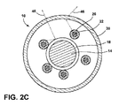
ここで図2Cを参照すると、複数の光拡散ファイバ22が、伝送媒体14および伝送ジャケット18を部分的にまたは実質的に取り囲むことがある。1つの実施の形態において、光拡散ファイバ22は、リボンが伝送ジャケット18の周りに折り畳まれた、リボン化形態であってよい。別の実施の形態において、光拡散ファイバ22は、伝送ケーブル10の異なる長さで、または伝送ケーブル10に沿った共通地点で、そのケーブル10から分岐してもよい。各々が光源42または別々の光源に光学的に結合された、より多くの光拡散ファイバ22を提供することにより、伝送ケーブル10をより強く照明することができる。その上、伝送媒体14の周りに多数の光拡散ファイバ22を配置することにより、伝送ケーブル10のより均一に分布した照明が達成されるであろう。必要に応じて、光拡散ファイバ22の各々が、異なる色を有する光を運び、照明された伝送ケーブル10内で光の静的または動的色混合を可能にしてもよい。
Referring now to FIG. 2C, a plurality of
ここで、図2Dに示された実施の形態を参照すると、伝送ケーブル10は一本の光拡散ファイバ22を備えることがある。そのような実施の形態において、光拡散ファイバ22は、側壁50から光46(図示せず)を散乱させる機能を果たしながら、伝送ケーブル10に沿って光信号を伝送することもできる。先に説明したように、光拡散ファイバ22の散乱構造は、可視スペクトル範囲内の光(例えば、可視光)を散乱させるのに十分なサイズであるが、信号スペクトル範囲内の光(例えば、近赤外線または紫外線波長)を散乱するほど十分に大きくないものであることがある。散乱構造のそのような形態により、光46の可視部分を散乱させ、伝送ケーブル10を照明しつつ、光46の光信号部分をケーブル10に亘って伝送し、実質的に散乱されないままにすることもできるであろう。別の実施の形態において、その光信号は、光46自体で運ばれてもよい。例えば、光源42は、変調が観察者により気付かれないが、それでも信号(例えば、音声信号、ビデオ信号、データ信号、および/または制御信号)を運ぶように、ヒトの眼に知覚できるよりも速く光46を変調してもよい。各々が光46を散乱させ、光信号を伝送できる、複数の光拡散ファイバ22を伝送ケーブル10に含ませてもよいことを理解すべきである。
Here, referring to the embodiment shown in FIG. 2D, the
ここで図3A〜Bを参照すると、照明された伝送ケーブル10は、必要に応じて、光拡散ファイバ22の側壁50上に配置された第1の導電片80および第2の導電片84を備えることがある。第1と第2の導電片80、84はファイバジャケット26により覆われてもよい。第1と第2の導電片80、84は、物理的気相成長法、導電性金属インク、透明導電性材料(例えば、インジウムスズ酸化物、フッ素スズ酸化物)、またはそれらの組合せによって施された導電性金属を含むことがある。第1と第2の導電片80、84の幅は、約20マイクロメートルと約100マイクロメートルの間であってよい。第1と第2の導電片80、84の厚さは、約10ナノメートル超、約100ナノメートル超、約1マイクロメートル超、約10マイクロメートル超、または100マイクロメートル超であってよい。第1と第2の導電片80、84は、伝送ケーブル10の長さに及ぶことがある。第1と第2の導電片80、84は、角度的に約180度間隔が離れて示されているが、約2度と約180度の間だけ離れて光拡散ファイバ22上に配置されてもよい。第1と第2の導電片80、84は、光拡散ファイバ22の長さに亘り互いに関する位置が変動してもよい。光拡散ファイバ22に沿った所定の位置で、例えば、電気通信を促進するために、互いに接近(例えば、約2度と約90度の間だけ離れて)してもよい。接地が別々に設けられているか、そうでなければ必要ないいくつかの実施の形態において、伝送ケーブル10は、1つしか導電片(例えば、第1のまたは第2の導電片80、84)を備えなくてもよい。伝送媒体14たまは伝送ジャケット18については示されていないが、第1と第2の導電片80、84を利用する実施の形態は、伝送媒体14および/または伝送ジャケット18も備えてよいことを理解すべきである。
Referring now to FIGS. 3A-B, the illuminated
動作において、第1と第2の導電片80、84は、伝送ケーブル10に沿って電流または電気信号を伝送するように構成されている。そのような実施の形態は、伝送媒体14および伝送ジャケット18をなくし、それゆえ、伝送ケーブル10のサイズと質量を減少させることができるという点で有利である。それに加え、電源に光拡散ファイバ22を設けることにより、ファイバ22を利用できる長さを延ばしてもよい。例えば、光拡散ファイバ22が長距離に亘ると、散乱光46の強度は、光源42からの距離が増すにつれて、美的に望ましいレベルより低く低下するであろう。そのような環境において、第1と第2の導電片80、84は、光拡散ファイバ22に光学的に結合した第2の光源92に電力を伝送することができる。第2の光源92を使用すると、伝送ケーブル10の照明の低下が、観察者に容易に明らかではないように、より多くの光46を光拡散ファイバ22に加えることができる。第1と第2の導電片80、84は、第1の光源42がなくても利用してよく、導電片80、84は、ファイバ22に光学的に結合された唯一の光源(例えば、第2の光源92)に電力を与えてもよいことを理解すべきである。
In operation, the first and second
第1と第2の導電片80、84を利用すると、導電片80、84を用いることのできる伝送ケーブル10に様々なセンサを組み込むことができる。例示のセンサとしては、第1と第2の導電片80、84の間の抵抗および/または静電容量で動作するものが挙げられる。図示された実施の形態において、接続点96が、伝送ケーブル10上に配置され、第1と第2の導電片80、84の両方と電気接触するように構成されている。伝送ケーブル10に沿って接続点96が移動すると、第1と第2の導電片80、84を通る抵抗が増減する。接続点96が導電片80、84に沿って動かされるときに、そのケーブルの抵抗の変化を測定することによって、信号を生成することができる。この信号は、ボリューム、散乱光46の強度、機器のモード、トラックの再生、または伝送ケーブル10に亘る通信を可能にするか否かなどの特徴を制御するために使用できる(例えば、電子機器44のコントローラにより)。その接続点96は、第1と第2の導電片80、84を利用できる容量性パッドまたは他のセンサなどの特徴と置き換えてもよいことを理解すべきである。さらに他の実施の形態において、伝送ケーブル10に亘り動かされる使用者の指が、第1と第2の導電片80、84の間の抵抗または静電容量を変化させ、それゆえ、その特徴を制御するのに十分であることがある。
When the first and second
ここで図4A〜Dを参照すると、使用者に音声情報(例えば、音楽、本、ガイドなしのツアーなど)を伝達するための、伝送ケーブル10の様々な実施の形態を利用したオーディオ・ヘッドセット(例えば、ヘッドフォン、イヤホンなど)の様々な実施の形態が示されている。ヘッドセット100は、一般に、第1の音声スピーカーアセンブリ104および第2の音声スピーカーアセンブリ108を備える。いくつかの実施の形態において、ヘッドセット100は、電子機器44(図1)から第1と第2の音声スピーカーアセンブリ104、108まで延在する伝送ケーブル10を備えることがある。そのような実施の形態において、伝送媒体14は、電気音声信号をヘッドセット100(第1と第2の音声スピーカーアセンブリ104、108)に伝達する働きをすることがあり、一方で、光拡散ファイバ22は伝送ケーブル10に照明を与える。あるいは、先に述べたように、光拡散ファイバ22は、伝送ケーブル10を照明し、かつヘッドセット100(例えば、第1と第2の音声スピーカーアセンブリ104、108)へとそこからの光信号を伝送してもよい。他の実施の形態において、ヘッドセット100は、ヘッドセット100自体内に延在する(例えば、ヘッドセット100内のコントローラから、第1と第2の音声スピーカーアセンブリ104、108、またはそれらの間)照明された伝送ケーブル10を含む無線形態であってもよい。
Referring now to FIGS. 4A-D, an audio headset utilizing various embodiments of the
ヘッドセット100または電子機器44に伝送ケーブル10を使用すると、ケーブル10により与えられる照明の動的制御が可能になるであろう。例えば、電子機器44またはヘッドセット100内に配置されたコントローラが光源42、および/または第2の光源92と通信して、光46の色、周波数および強度を変えてもよい。例えば、流れている音楽のタイプに基づいて、コントローラは、ケーブル10の照明色を変えても、音楽のビートと同期するように発光をパルスにしても、または音楽に可視化効果を与えてもよい。他の実施の形態において、使用者は、電子機器44またはヘッドセット100の安全性または緊急事態の設定を作動させて、観察者の注意を引くように構成された周波数および色でケーブル10を点滅させてもよい。
The use of the
図4Aおよび4Bは、電子機器44から第1と第2の音声スピーカーアセンブリ104、108の両方に延在するただ1つの伝送ケーブル10を有するヘッドセット100の実施の形態を示している。第1と第2の音声スピーカーアセンブリ104、108は両方とも、支持部材120に結合されている。支持部材120は、ヘッドセット100の使用者の頭部の後ろを包み、第1と第2の音声スピーカーアセンブリ104、108を使用者の耳に近接して位置付けるように構成されている。伝送ケーブル10は、支持部材120に結合されており、支持部材120でヘッドセット100の使用者の頭部の後ろを包むように構成されている。伝送ケーブル10は、散乱光46が傍観者に見えて、美的および/または安全性機能を与えるように、支持部材120の外部に結合されていてもよい。あるいは、伝送ケーブル10は、散乱光46が支持部材120から出られるように、支持部材120の光透過性の実施の形態の内部に配置されてもよい。伝送ケーブル10を支持部材120に結合することによって、ケーブル10は、光46または(例えば、光および/または電気)信号の損失をもたらし得るきつい曲げが光拡散ファイバ22または伝送媒体14に生じるのを避ける。それに加え、支持部材120は、支持部材120および伝送ケーブル10の曲げに抵抗するように構成された剛性材料または構造を含んでもよい。伝送ケーブル10は、第2の音声スピーカーアセンブリ108を越えて延在し、筐体124内で終わる。筐体124は、電子機器44またはヘッドセット100についての特徴(例えば、ボリューム、トラック、光の強度、機器のモードなど)を制御できるコントロール機器128(例えば、ボタン、スライドなど)を備えることがある。コントロール機器128からの信号は、伝送媒体14、第1と第2の導電片80、84、および/または光拡散ファイバ22で、電子機器44のコントローラまたはヘッドセット100に運ばれてよい。
FIGS. 4A and 4B illustrate an embodiment of a
光拡散ファイバ22に入る光46の全てが散乱されるとは限らないであろう。いくつかの実施の形態において、光源42からの光46の一部のみが光拡散ファイバ22に到達し、筐体124を照らす。光源42が筐体124内に配置されていても、または第2の光源92を利用する実施の形態において、第2の光源92が筐体124内に配置されていてもよいことを理解すべきである。
Not all of the light 46 entering the
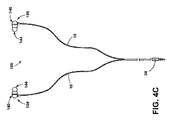
ここで図4Cを参照すると、ヘッドセット100の音声スピーカーアセンブリ104、108は、イヤホンおよび/またはインイヤー・ヘッドフォンの形態にあることがある。図示された実施の形態において、ヘッドセット100は、各々が第1と第2の音声スピーカーアセンブリ104、108の一方に接続された、2つの照明される伝送ケーブル10を用いることができる。第1と第2の音声スピーカーアセンブリ104、108の各々は、ケーシング140およびインイヤー部材144を備え、そのいずれかが、光拡散ファイバ22と光学的に結合され、輝くように構成されることがある。それらの伝送ケーブル10は別々の光源を有し、照明色および周波数の独立した動的制御を可能にしてもよい。
Referring now to FIG. 4C, the
ここで図4Dに図示された実施の形態を参照すると、ヘッドセット100は、無線式のオーバーヘッドバンド式のヘッドセットであることがある。ヘッドセット100は、第1と第2の音声スピーカーアセンブリ104、108の間の接続体として働くヘッドバンド160を備える。第1と第2の音声スピーカーアセンブリ104、108は、外部カバー168に結合したオンイヤー/オーバーイヤー・カップ164を備える。ヘッドバンド160は、第1と第2の音声スピーカーアセンブリ104、108に結合されており、使用中に使用者の頭上に延在する。ヘッドセット100は、電子機器44および/またはヘッドセット100の少なくとも1つの特徴(例えば、ボリューム、トラックの選択、かかってきた電話への切換え、機器のモードなど)の制御に使用されるボタン172を備えることがある。
Referring now to the embodiment illustrated in FIG. 4D, the
ヘッドバンド160は、ヘッドバンド160およびヘッドセット100のエッジ180の周囲に広がる照明された伝送ケーブル10を有するものとして示されている。照明された伝送ケーブル10は、散乱光46でヘッドセット100に見て美しい照明を与える上に、第1と第2の音声スピーカーアセンブリ104、108またはヘッドセット100内のコントローラの間のデータおよび音声信号を伝送する働きをすることがある。ヘッドセット100は、ヘッドセット100およびヘッドバンド160の周囲に配置された1つ以上の導波路184を備えることがある。図示された実施の形態において、導波路184は、ヘッドバンド160の内面と外面の両方の中央領域に沿って延在しているが、ヘッドバンド160の全体に亘り延在してもよい。導波路184は、連続構造として示されているが、半連続または不連続構造を形成する複数の導波路184を含んでもよいことを理解すべきである。導波路184は、アクリル樹脂、エポキシ樹脂、ウレタン樹脂およびフッ化炭素樹脂、シリコーンゴム、並びにこれらの材料の複合樹脂などの光を透過させられ透明材料から形成されてもよい。それに加え、またはそれに代えて、ヘッドバンド160は、伝送ケーブル10と光学的に連通し、照明されるように構成されることがある1つ以上のロゴまたはデカールを備えることがある。外部カバー168およびオンイヤー/オーバーイヤー・カップ164は、伝送ケーブル10に光学的に結合され、よって、ヘッドセット100に追加の照明を与えてもよいことを理解すべきである。
The
ここで図5Aを参照すると、ヘッドバンド160のエッジ180が、そこに結合された伝送ケーブル10を有することがある。伝送ケーブル10は、様々な様式でヘッドバンド160に結合されてよい。例えば、機械的に固定する実施の形態において、伝送ケーブル10は、ヘッドバンド160のエッジ180に画成された溝に結合される、複数の小穴に通される、または伝送ケーブル10をヘッドバンド160に取り付ける少なくとも1つの留め具を有することがある。接着により結合する実施の形態において、伝送ケーブル10は、透明な接着剤を使用して、ヘッドバンド160に接着されることがある。いくつかの実施の形態において、導波路184がヘッドバンド160のエッジ180間に延在してもよい。そのような実施の形態において、伝送ケーブル10からの散乱光46は、導波路184に入り、導波路184の側部照明を与えることがある。
Referring now to FIG. 5A, the
ここで図5Bを参照すると、伝送ケーブル10は、導波路184の下面に画成された溝188を通じて延在することがある。そのような構成において、伝送ケーブル10からの散乱光46は、導波路184に入り、導波路184全体に分散されて、導波路184から落ち着いた輝きを生じる。導波路184は、光46を拡散させるように構成された複数の散乱構造を含むことがある。それに加え、導波路184は、ヘッドセット100に落ち着いて輝く照明を与えるために、光46の拡散に役立つコーティングを有することがある。
Referring now to FIG. 5B, the
請求項の精神または範囲から逸脱せずに、様々な改変および変更が可能であることが当業者に明白であろう。 It will be apparent to those skilled in the art that various modifications and variations can be made without departing from the spirit or scope of the claims.
以下、本発明の好ましい実施形態を項分け記載する。 Hereinafter, preferable embodiments of the present invention will be described in terms of items.
実施形態1
ヘッドフォンシステムにおいて、
第1の音声スピーカーアセンブリと第2の音声スピーカーアセンブリ、
前記第1と第2の音声スピーカーアセンブリの間に延在する接続体、
前記接続体に結合された光拡散ファイバであって、該光拡散ファイバがガラスコアとクラッドを有し、前記ガラスコアおよびコアとクラッドの界面の少なくとも一方は複数の光散乱構造を有する、光拡散ファイバ、および
前記光拡散ファイバに光学的に結合されており、光を該光拡散ファイバに放射するように構成された光源、
を備え、
前記光散乱構造が、放射光を散乱させ、該放射光を該光拡散ファイバの側壁に少なくとも部分的に沿って出力するように構成されている、ヘッドフォンシステム。
Embodiment 1
In the headphone system,
A first audio speaker assembly and a second audio speaker assembly;
A connection extending between the first and second audio speaker assemblies;
A light diffusion fiber coupled to the connection body, wherein the light diffusion fiber has a glass core and a cladding, and at least one of the glass core and the interface between the core and the cladding has a plurality of light scattering structures. A light source that is optically coupled to the light diffusing fiber and configured to emit light to the light diffusing fiber;
With
A headphone system, wherein the light scattering structure is configured to scatter emitted light and output the emitted light at least partially along a sidewall of the light diffusing fiber.
実施形態2
前記光拡散ファイバが、前記接続体のエッジに沿って配置された溝により位置付けられている、実施形態1に記載のヘッドフォンシステム。
Embodiment 2
The headphone system according to embodiment 1, wherein the light diffusion fiber is positioned by a groove disposed along an edge of the connection body.
実施形態3
前記散乱構造が、約10ナノメートルと約1マイクロメートルの間の直径を有する、および/またはガス入り空隙を含む、実施形態1または2に記載のヘッドフォンシステム。
Embodiment 3
The headphone system of embodiment 1 or 2, wherein the scattering structure has a diameter between about 10 nanometers and about 1 micrometer and / or includes a gas-filled void.
実施形態4
前記接続体が半透明材料を含み、該接続体が、前記ファイバに光学的に結合されており、該ファイバから放射された光を該接続体に通して誘導するように構成されている、実施形態1から3いずれか1つに記載のヘッドフォンシステム。
Embodiment 4
The connector includes a translucent material, the connector is optically coupled to the fiber, and configured to direct light emitted from the fiber through the connector; The headphone system according to any one of Forms 1 to 3.
実施形態5
前記第1と第2の音声スピーカーアセンブリが、前記光拡散ファイバと光学的に連通したそれぞれ第1と第2の端部キャップを備える、実施形態1から4いずれか1つに記載のヘッドフォンシステム。
Embodiment 5
5. The headphone system of any one of embodiments 1-4, wherein the first and second audio speaker assemblies comprise first and second end caps, respectively, in optical communication with the light diffusing fiber.
実施形態6
ヘッドフォンシステムにおいて、
第1の音声スピーカーアセンブリと第2の音声スピーカーアセンブリ、
ガラスコアとクラッドを有する光拡散ファイバであって、該ガラスコアおよびコアとクラッドの界面の少なくとも一方が複数の散乱構造を有し、前記光拡散ファイバは、光を該光拡散ファイバに放射する光源と光学的に結合するように構成されており、前記散乱構造は、放射光を散乱させ、該放射光を該光拡散ファイバの側壁の少なくとも一部に沿って出力するように構成されている、光拡散ファイバ、
前記光拡散ファイバと共線的に延在する導電体、および
前記光拡散ファイバに光学的に結合されており、該光拡散ファイバにより照らされるように構成されているプラグ、
を備えたヘッドフォンシステム。
Embodiment 6
In the headphone system,
A first audio speaker assembly and a second audio speaker assembly;
A light diffusing fiber having a glass core and a clad, wherein at least one of the interface between the glass core and the core and the clad has a plurality of scattering structures, and the light diffusing fiber emits light to the light diffusing fiber. The scattering structure is configured to scatter the emitted light and to output the emitted light along at least a portion of the side wall of the light diffusing fiber. Light diffusion fiber,
A conductor extending collinearly with the light diffusing fiber; and a plug optically coupled to the light diffusing fiber and configured to be illuminated by the light diffusing fiber;
Headphone system with
実施形態7
前記導電体および前記光拡散ファイバの周囲にジャケットが配置されている、実施形態6に記載のヘッドフォンシステム。
Embodiment 7
The headphone system according to embodiment 6, wherein a jacket is disposed around the conductor and the light diffusion fiber.
実施形態8
前記散乱構造が、約10ナノメートルと約1マイクロメートルの間の直径を有し、ガス入り空隙を含むことがある、実施形態7に記載のヘッドフォンシステム。
Embodiment 8
The headphone system of embodiment 7, wherein the scattering structure may have a diameter between about 10 nanometers and about 1 micrometer and include gas-filled voids.
実施形態9
前記第1と第2の音声スピーカーアセンブリの少なくとも一方が、前記光拡散ファイバに光学的に結合され、かつ該光拡散ファイバに照らされるように構成されたケーシングを備える、実施形態6から8いずれか1つに記載のヘッドフォンシステム。
Embodiment 9
Embodiments 6-8, wherein at least one of the first and second audio speaker assemblies comprises a casing optically coupled to the light diffusing fiber and configured to be illuminated by the light diffusing fiber. The headphone system according to one.
実施形態10
ヘッドセットにおいて、
第1の音声スピーカーアセンブリと第2の音声スピーカーアセンブリ、
複数の内部散乱構造および側壁を有するただ1つの光拡散ファイバ、
前記光拡散ファイバに光学的に結合されており、光を該第1の端部に放射するように構成されたただ1つの光源であって、放射光の少なくともいくらかが、前記光拡散ファイバの側壁の少なくとも一部に沿って出力される、ただ1つの光源、および
前記光拡散ファイバと共線的に延在する伝送媒体であって、前記第1と第2の音声スピーカーアセンブリと通信する伝送媒体、
を備えるヘッドセット。
In the headset,
A first audio speaker assembly and a second audio speaker assembly;
A single light diffusing fiber having a plurality of internal scattering structures and sidewalls;
A single light source optically coupled to the light diffusing fiber and configured to emit light to the first end, wherein at least some of the emitted light is a sidewall of the light diffusing fiber. A single light source that is output along at least a portion of the transmission line, and a transmission medium that extends collinearly with the light diffusing fiber and communicates with the first and second audio speaker assemblies ,
With headset.
実施形態11
ケーブルジャケットが、前記光拡散ファイバおよび前記伝送媒体の両方を取り囲み、光輝性材料を含み、該伝送媒体が、光輝性材料を含む伝送ジャケットにより取り囲まれている、実施形態10に記載のヘッドセット。
Embodiment 11
Embodiment 11. The headset of
実施形態12
前記散乱構造が、約10ナノメートルと約1マイクロメートルの間の直径を有し、ガス入り空隙を含む、実施形態11に記載のヘッドセット。
Embodiment 12
The headset of embodiment 11, wherein the scattering structure has a diameter between about 10 nanometers and about 1 micrometer and includes gas-filled voids.
実施形態13
前記光拡散ファイバ上に配置された第1の導電片、および
該光拡散ファイバ上に配置された第2の導電片、
をさらに備え、
前記第1と第2の導電片が前記光拡散ファイバ上に印刷されている、実施形態10から12いずれか1つに記載のヘッドセット。
Embodiment 13
A first conductive piece disposed on the light diffusing fiber; and a second conductive piece disposed on the light diffusing fiber;
Further comprising
The headset according to any one of
実施形態14
前記第1と第2の導電片と電気通信しており、前記光拡散ファイバの長さに沿って動かせる接続点をさらに備える、実施形態13に記載のヘッドセット。
The headset of embodiment 13, further comprising a connection point in electrical communication with the first and second conductive pieces and movable along the length of the light diffusing fiber.
実施形態15
前記第1と第2の導電片の少なくとも一方が透明導電性材料を含む、実施形態13に記載のヘッドセット。
Embodiment 15
The headset according to embodiment 13, wherein at least one of the first and second conductive pieces includes a transparent conductive material.
実施形態16
筐体が、前記光拡散ファイバの端部に配置され、該光拡散ファイバから出る放出光により照らされる、実施形態10に記載のヘッドセット。
Embodiment 16
Embodiment 11. The headset of
実施形態17
支持部材が前記第1と第2の音声スピーカーアセンブリの間に延在し、前記光拡散ファイバが該支持部材に結合されている、実施形態10に記載のヘッドセット。
Embodiment 17
The headset of
実施形態18
前記伝送媒体が、音声信号を前記第1と第2の音声スピーカーアセンブリに伝送するように構成されている、実施形態10に記載のヘッドセット。
The headset of
実施形態19
前記光拡散ファイバが、約50dB/km超の前記放射光の散乱誘起減衰を有する、実施形態10に記載のヘッドセット。
Embodiment 19
Embodiment 11. The headset of
実施形態20
前記第1と第2の音声スピーカーアセンブリの少なくとも一方が、前記光拡散ファイバに光学的に結合され、かつ該光拡散ファイバに照らされるように構成されたケーシングを備える、実施形態10に記載のヘッドセット。
Embodiment 20.
The head of
実施形態21
前記導電体が、音声信号を前記第1と第2の音声スピーカーアセンブリに伝送するように構成されている、実施形態6から9いずれか1つに記載のヘッドフォンシステム。
Embodiment 21.
10. A headphone system according to any one of embodiments 6 to 9, wherein the electrical conductor is configured to transmit audio signals to the first and second audio speaker assemblies.
実施形態22
ケーブルジャケットが、前記光拡散ファイバおよび前記導電体の両方を取り囲む、実施形態6から9いずれか1つに記載のヘッドフォンシステム。
実施形態23
前記ケーブルジャケットが光輝性材料を含む、実施形態22に記載のヘッドフォンシステム。
Embodiment 23
Embodiment 23. A headphone system according to
実施形態24
前記ケーブルジャケットが透明である、実施形態22に記載のヘッドフォンシステム。
Embodiment 24.
The headphone system of
実施形態25
前記筐体が、前記光拡散ファイバに光学的に結合されており、該光拡散ファイバから出る光により照らされるように構成されている、実施形態1から11いずれか1つに記載のヘッドフォンシステム。
Embodiment 25
12. The headphone system according to any one of embodiments 1-11, wherein the housing is optically coupled to the light diffusing fiber and configured to be illuminated by light exiting the light diffusing fiber.
実施形態26
前記導電体が、音声信号を前記第1と第2の音声スピーカーアセンブリに伝送するように構成されている、実施形態1から25いずれか1つに記載のヘッドフォンシステム。
26. A headphone system according to any one of embodiments 1-25, wherein the electrical conductor is configured to transmit audio signals to the first and second audio speaker assemblies.
10 照明可能な伝送ケーブル
14 伝送媒体
18 伝送ジャケット
22 光拡散ファイバ
26 ファイバジャケット
30 ケーブルジャケット
34 第1のデータプラグ
38 第2のデータプラグ
42 光源
44 電子機器
46 光、放射光、散乱光
50 側壁
54 ガラスコア
58 クラッド層
66 光反射体
80 第1の導電片
84 第2の導電片
92 第2の光源
96 接続点
100 ヘッドセット
104 第1の音声スピーカーアセンブリ
108 第2の音声スピーカーアセンブリ
120 支持部材
124 筐体
160 ヘッドバンド
184 導波路
DESCRIPTION OF
Claims (5)
第1の音声スピーカーアセンブリと第2の音声スピーカーアセンブリ、
ガラスコアとクラッドを有する光拡散ファイバであって、該ガラスコアおよびコアとクラッドの界面の少なくとも一方が複数の散乱構造を有し、前記光拡散ファイバは、光を該光拡散ファイバに放射する光源と光学的に結合するように構成されており、前記散乱構造は、放射光を散乱させ、該放射光を前記光拡散ファイバの側壁の少なくとも一部に沿って出力するように構成されている、光拡散ファイバ、
前記光拡散ファイバと共線的に延在する導電体、および
前記光拡散ファイバに光学的に結合されており、該光拡散ファイバにより照らされるように構成されているプラグ、
を備えたヘッドフォンシステム。 In the headphone system,
A first audio speaker assembly and a second audio speaker assembly;
A light diffusing fiber having a glass core and a clad, wherein at least one of the interface between the glass core and the core and the clad has a plurality of scattering structures, and the light diffusing fiber emits light to the light diffusing fiber. The scattering structure is configured to scatter the emitted light and output the emitted light along at least a portion of the side wall of the light diffusing fiber. Light diffusion fiber,
A conductor extending collinearly with the light diffusing fiber; and a plug optically coupled to the light diffusing fiber and configured to be illuminated by the light diffusing fiber;
Headphone system with
Applications Claiming Priority (4)
| Application Number | Priority Date | Filing Date | Title |
|---|---|---|---|
| US201461992569P | 2014-05-13 | 2014-05-13 | |
| US14/702,042 US9813801B2 (en) | 2014-05-13 | 2015-05-01 | Illuminated headphone system |
| US14/702,042 | 2015-05-01 | ||
| PCT/US2016/029991 WO2016178958A1 (en) | 2015-05-01 | 2016-04-29 | Illuminated headphone system |
Publications (1)
| Publication Number | Publication Date |
|---|---|
| JP2018519710A true JP2018519710A (en) | 2018-07-19 |
Family
ID=54539074
Family Applications (2)
| Application Number | Title | Priority Date | Filing Date |
|---|---|---|---|
| JP2017557053A Pending JP2018524761A (en) | 2014-05-13 | 2016-04-29 | Illuminable transmission cable |
| JP2017557064A Abandoned JP2018519710A (en) | 2014-05-13 | 2016-04-29 | Illuminated headphone system |
Family Applications Before (1)
| Application Number | Title | Priority Date | Filing Date |
|---|---|---|---|
| JP2017557053A Pending JP2018524761A (en) | 2014-05-13 | 2016-04-29 | Illuminable transmission cable |
Country Status (3)
| Country | Link |
|---|---|
| US (2) | US9813801B2 (en) |
| JP (2) | JP2018524761A (en) |
| CN (1) | CN107852537B (en) |
Cited By (1)
| Publication number | Priority date | Publication date | Assignee | Title |
|---|---|---|---|---|
| KR200496026Y1 (en) * | 2022-04-26 | 2022-10-18 | 주식회사 한미마이크로닉스 | Luminous headphone |
Families Citing this family (23)
| Publication number | Priority date | Publication date | Assignee | Title |
|---|---|---|---|---|
| WO2016178961A2 (en) * | 2015-05-01 | 2016-11-10 | Corning Incorporated | Illuminable transmission cable |
| US9813801B2 (en) * | 2014-05-13 | 2017-11-07 | Corning Incorporated | Illuminated headphone system |
| EP3289773A1 (en) * | 2015-05-01 | 2018-03-07 | Corning Incorporated | Illuminated headphone system |
| US10111014B2 (en) | 2015-08-10 | 2018-10-23 | Team Ip Holdings, Llc | Multi-source audio amplification and ear protection devices |
| US10047459B1 (en) | 2015-10-07 | 2018-08-14 | Google Llc | Interactive cord |
| US10083289B1 (en) | 2015-10-07 | 2018-09-25 | Google Llc | Authentication using an interactive cord |
| US9807852B1 (en) | 2015-11-02 | 2017-10-31 | Google Inc. | Interactive cord with integrated light sources |
| CN105513709B (en) * | 2016-01-21 | 2017-12-01 | 殷峥凯 | A kind of acousto-optic audio signal wire |
| FR3049332A1 (en) * | 2016-03-22 | 2017-09-29 | Zedel | FRONT LAMP WITH REAR SIGNALING |
| CN106051522A (en) * | 2016-07-27 | 2016-10-26 | 广东佳禾声学科技有限公司 | Light-emitting wire |
| JP6772749B2 (en) * | 2016-10-14 | 2020-10-21 | 住友電気工業株式会社 | Phone plug and phone jack |
| US10222924B2 (en) | 2016-11-25 | 2019-03-05 | Google Llc | Interactive cord with resistance touchpoints |
| US10701473B2 (en) * | 2016-11-29 | 2020-06-30 | Team Ip Holdings, Llc | Audio amplification devices with integrated light elements for enhanced user safety |
| US10775577B2 (en) * | 2017-01-17 | 2020-09-15 | Cheng Sean Chen | Cable assembly having a connector capable of emitting optical signals and a visible light |
| US10649168B2 (en) * | 2017-05-31 | 2020-05-12 | Molex, Llc | Illuminated tracer cable |
| US10015576B1 (en) * | 2017-11-12 | 2018-07-03 | Keith Mungin | Headphones with coordinated external illumination |
| US20190224491A1 (en) * | 2018-01-19 | 2019-07-25 | Bose Corporation | Peripherally focused light from wearable audio interfaces |
| DE102018113970B4 (en) | 2018-06-12 | 2021-03-18 | Leoni Kabel Gmbh | Cable with light emitting element |
| US10645487B2 (en) * | 2018-07-23 | 2020-05-05 | Warped Dynamics, LLC | Vertically configured parametric transducer headphones |
| WO2022019898A1 (en) * | 2020-07-22 | 2022-01-27 | Luca Zanetti | Multimedia patch cord for optical cable mpo added with electric data for smart home and entertainment |
| US11570541B2 (en) * | 2021-04-30 | 2023-01-31 | Logitech Europe S.A. | Dynamic lighting for an audio device |
| USD983768S1 (en) * | 2022-10-08 | 2023-04-18 | Yingshan Wu | Earphone |
| USD1003271S1 (en) * | 2023-03-15 | 2023-10-31 | Shiping Hu | Headphone |
Family Cites Families (36)
| Publication number | Priority date | Publication date | Assignee | Title |
|---|---|---|---|---|
| US4466697A (en) * | 1981-11-12 | 1984-08-21 | Maurice Daniel | Light dispersive optical lightpipes and method of making the same |
| JPH03200108A (en) | 1989-12-27 | 1991-09-02 | Tatsuta Electric Wire & Cable Co Ltd | Electrically conductive optical fiber |
| US5617497A (en) | 1993-05-21 | 1997-04-01 | Super Vision International, Inc. | Lateral illumination fiber optic cable device and method of manufacture |
| JPH07113919A (en) * | 1993-10-20 | 1995-05-02 | Mitsubishi Rayon Co Ltd | Lighting plastic optical fiber tube |
| US5737472A (en) * | 1993-12-17 | 1998-04-07 | Audio-Images S.A.R.L. | Optical fiber with multiple point lateral illumination |
| US5469523A (en) * | 1994-06-10 | 1995-11-21 | Commscope, Inc. | Composite fiber optic and electrical cable and associated fabrication method |
| US6931183B2 (en) * | 1996-03-29 | 2005-08-16 | Dominion Lasercom, Inc. | Hybrid electro-optic cable for free space laser antennas |
| JP2000284154A (en) * | 1999-03-29 | 2000-10-13 | Nec Corp | Communication cable having identification means and method for identification of communication cable |
| US6879688B2 (en) | 2000-11-09 | 2005-04-12 | Lighten-Up, Llc | Telephone headset with indicator light |
| US20050074216A1 (en) * | 2000-12-21 | 2005-04-07 | Shinichi Irie | Side-illumination type optical fiber |
| US20030215197A1 (en) * | 2002-05-14 | 2003-11-20 | Simon Jonathan N. | Combined optical and electrical transmission line |
| CN2688008Y (en) | 2004-02-06 | 2005-03-23 | 杨谦霖 | Colour luminous earphone |
| WO2005106899A1 (en) * | 2004-04-29 | 2005-11-10 | University Of Technology, Sydney | An optically traceable transmission cable for transmitting data or electricity and a traceable conduit |
| US7386203B2 (en) * | 2005-06-30 | 2008-06-10 | Lawrence Livermore National Security, Llc | System for diffusing light from an optical fiber or light guide |
| US20070081690A1 (en) | 2005-09-20 | 2007-04-12 | Stagni Mary K | Electroluminescent lighted headphones |
| US7450806B2 (en) | 2005-11-08 | 2008-11-11 | Corning Incorporated | Microstructured optical fibers and methods |
| US20070201227A1 (en) | 2006-02-27 | 2007-08-30 | Camp William O Jr | Light cable accessory for an electronic device and methods of operating a lighted cable accessory for an electronic device |
| US7505660B2 (en) | 2006-06-30 | 2009-03-17 | Corning Incorporated | Microstructured transmission optical fiber |
| DE102006061164B4 (en) | 2006-12-22 | 2018-12-27 | Osram Opto Semiconductors Gmbh | Light-emitting device |
| JP2010520496A (en) | 2007-02-28 | 2010-06-10 | コーニング インコーポレイテッド | Wide effective area optical fiber |
| US8045858B2 (en) | 2008-07-24 | 2011-10-25 | The Boeing Company | Methods and systems for providing full avionics data services over a single fiber |
| EP2302294A1 (en) | 2009-09-18 | 2011-03-30 | 3M Innovative Properties Company | Connector |
| US8509453B2 (en) * | 2009-10-29 | 2013-08-13 | Google Inc. | Luminescent headphones without battery packs |
| EP2502101B2 (en) | 2009-11-20 | 2021-11-17 | Corning Incorporated | Illumination system with side-emitting optical photonic fibre and manufacturing method thereof |
| US8787717B2 (en) | 2011-04-26 | 2014-07-22 | Corning Incorporated | Systems and methods for coupling light into a transparent sheet |
| US8724942B2 (en) | 2011-04-26 | 2014-05-13 | Corning Incorporated | Light-coupling optical systems and methods employing light-diffusing optical fiber |
| US8620125B2 (en) | 2011-04-29 | 2013-12-31 | Corning Incorporated | Light diffusing fibers and methods for making the same |
| US8805141B2 (en) | 2011-10-07 | 2014-08-12 | Corning Incorporated | Optical fiber illumination systems and methods |
| US9217826B2 (en) | 2011-10-11 | 2015-12-22 | Corning Incorporated | Multi-wavelength light source using light diffusing fibers |
| US9093003B2 (en) | 2011-10-11 | 2015-07-28 | Corning Incorporated | Manipulation of color illumination using light diffusing fiber |
| EP2590428A3 (en) * | 2011-11-04 | 2014-01-22 | GN Netcom A/S | Headset with a light emitting neckband |
| US20140363134A1 (en) | 2013-06-10 | 2014-12-11 | Corning Optical Communications LLC | Optical fiber cable assembly comprising optical tracer fiber |
| US9429731B2 (en) | 2013-08-12 | 2016-08-30 | Corning Optical Communications LLC | Optical fiber cable assembly comprising optical tracer fiber |
| US9813801B2 (en) * | 2014-05-13 | 2017-11-07 | Corning Incorporated | Illuminated headphone system |
| US20150373449A1 (en) | 2014-06-24 | 2015-12-24 | Matthew D. Jackson | Illuminated audio cable |
| US9304278B1 (en) * | 2015-03-31 | 2016-04-05 | Corning Optical Communications LLC | Traceable cable with side-emitting optical fiber and method of forming the same |
-
2015
- 2015-05-01 US US14/702,042 patent/US9813801B2/en not_active Expired - Fee Related
- 2015-05-01 US US14/702,005 patent/US9628898B2/en active Active
-
2016
- 2016-04-29 CN CN201680038381.XA patent/CN107852537B/en not_active Expired - Fee Related
- 2016-04-29 JP JP2017557053A patent/JP2018524761A/en active Pending
- 2016-04-29 JP JP2017557064A patent/JP2018519710A/en not_active Abandoned
Cited By (1)
| Publication number | Priority date | Publication date | Assignee | Title |
|---|---|---|---|---|
| KR200496026Y1 (en) * | 2022-04-26 | 2022-10-18 | 주식회사 한미마이크로닉스 | Luminous headphone |
Also Published As
| Publication number | Publication date |
|---|---|
| US20150332810A1 (en) | 2015-11-19 |
| US9628898B2 (en) | 2017-04-18 |
| US9813801B2 (en) | 2017-11-07 |
| JP2018524761A (en) | 2018-08-30 |
| CN107852537A (en) | 2018-03-27 |
| CN107852537B (en) | 2020-04-10 |
| US20150334485A1 (en) | 2015-11-19 |
Similar Documents
| Publication | Publication Date | Title |
|---|---|---|
| JP2018519710A (en) | Illuminated headphone system | |
| JP2018524761A5 (en) | ||
| US8651750B2 (en) | Audio connectors with optical structures and electrical contacts | |
| US8577195B2 (en) | Interface accessories with optical and electrical paths | |
| JP6143753B2 (en) | Cable and electronics | |
| JP6087510B2 (en) | Cable and cable identification method | |
| US8573861B2 (en) | Audio jacks with optical and electrical paths | |
| US8718294B2 (en) | Audio connectors with wavelength-division-multiplexing capabilities | |
| US9510081B2 (en) | Lighting earphone | |
| CN103492793A (en) | Systems and methods for coupling light into a transparent sheet | |
| CN101909410A (en) | Electronic equipment with light source | |
| CN113132598B (en) | Breathing lamp assembly, camera assembly and electronic equipment | |
| JP5478116B2 (en) | Optical fiber | |
| CN210296811U (en) | Light-emitting flat cable structure | |
| WO2016178961A2 (en) | Illuminable transmission cable | |
| EP3289773A1 (en) | Illuminated headphone system | |
| CN206531985U (en) | Laser reflection microscope group, emitting optical fiber, laser fiber-optic transmission device and luminous earphone | |
| TWI738562B (en) | Cable assembly and cable indication system | |
| CN107181530A (en) | Fiber optical transceiver | |
| CN110519424A (en) | The shell and electronic equipment of electronic equipment | |
| KR20170008543A (en) | Cable For Universal Serial Bus Specification | |
| CN104977669B (en) | A kind of optical fiber transmission line, optical fiber transmission method, output intent and device | |
| CN204217124U (en) | A kind of luminous microphone wire with reflective functions | |
| CN204305303U (en) | A kind of flat earphone cord | |
| JP5622297B2 (en) | Optical fiber |
Legal Events
| Date | Code | Title | Description |
|---|---|---|---|
| A621 | Written request for application examination |
Free format text: JAPANESE INTERMEDIATE CODE: A621 Effective date: 20190412 |
|
| A762 | Written abandonment of application |
Free format text: JAPANESE INTERMEDIATE CODE: A762 Effective date: 20200417 |
|
| A977 | Report on retrieval |
Free format text: JAPANESE INTERMEDIATE CODE: A971007 Effective date: 20200416 |