JP2018508916A - IoT communication across power switches - Google Patents

IoT communication across power switches Download PDF

Info

Publication number
JP2018508916A
JP2018508916A JP2017554246A JP2017554246A JP2018508916A JP 2018508916 A JP2018508916 A JP 2018508916A JP 2017554246 A JP2017554246 A JP 2017554246A JP 2017554246 A JP2017554246 A JP 2017554246A JP 2018508916 A JP2018508916 A JP 2018508916A
Authority
JP
Japan
Prior art keywords
devices
power switch
power
registered trademark
controlled
Prior art date
Legal status (The legal status is an assumption and is not a legal conclusion. Google has not performed a legal analysis and makes no representation as to the accuracy of the status listed.)
Withdrawn
Application number
JP2017554246A
Other languages
Japanese (ja)
Other versions
JP2018508916A5 (en
Inventor
ポール ブラントナー
ポール ブラントナー
マイケル テトロー
マイケル テトロー
エリック ファーガソン
エリック ファーガソン
デイヴィッド デイヴィス
デイヴィッド デイヴィス
ショーン モンティス
ショーン モンティス
マイケル マーレイ
マイケル マーレイ
ブラダン ジャコビッチ
ブラダン ジャコビッチ
Original Assignee
アイデバイシーズ エルエルシー
アイデバイシーズ エルエルシー
Priority date (The priority date is an assumption and is not a legal conclusion. Google has not performed a legal analysis and makes no representation as to the accuracy of the date listed.)
Filing date
Publication date
Application filed by アイデバイシーズ エルエルシー, アイデバイシーズ エルエルシー filed Critical アイデバイシーズ エルエルシー
Publication of JP2018508916A publication Critical patent/JP2018508916A/en
Publication of JP2018508916A5 publication Critical patent/JP2018508916A5/ja
Withdrawn legal-status Critical Current

Links

Images

Classifications

    • HELECTRICITY
    • H04ELECTRIC COMMUNICATION TECHNIQUE
    • H04LTRANSMISSION OF DIGITAL INFORMATION, e.g. TELEGRAPHIC COMMUNICATION
    • H04L67/00Network arrangements or protocols for supporting network services or applications
    • H04L67/01Protocols
    • H04L67/12Protocols specially adapted for proprietary or special-purpose networking environments, e.g. medical networks, sensor networks, networks in vehicles or remote metering networks
    • H04L67/125Protocols specially adapted for proprietary or special-purpose networking environments, e.g. medical networks, sensor networks, networks in vehicles or remote metering networks involving control of end-device applications over a network
    • HELECTRICITY
    • H04ELECTRIC COMMUNICATION TECHNIQUE
    • H04LTRANSMISSION OF DIGITAL INFORMATION, e.g. TELEGRAPHIC COMMUNICATION
    • H04L12/00Data switching networks
    • H04L12/02Details
    • H04L12/12Arrangements for remote connection or disconnection of substations or of equipment thereof
    • HELECTRICITY
    • H04ELECTRIC COMMUNICATION TECHNIQUE
    • H04LTRANSMISSION OF DIGITAL INFORMATION, e.g. TELEGRAPHIC COMMUNICATION
    • H04L12/00Data switching networks
    • H04L12/28Data switching networks characterised by path configuration, e.g. LAN [Local Area Networks] or WAN [Wide Area Networks]
    • H04L12/2803Home automation networks
    • H04L12/2823Reporting information sensed by appliance or service execution status of appliance services in a home automation network
    • HELECTRICITY
    • H04ELECTRIC COMMUNICATION TECHNIQUE
    • H04LTRANSMISSION OF DIGITAL INFORMATION, e.g. TELEGRAPHIC COMMUNICATION
    • H04L41/00Arrangements for maintenance, administration or management of data switching networks, e.g. of packet switching networks
    • H04L41/04Network management architectures or arrangements
    • HELECTRICITY
    • H04ELECTRIC COMMUNICATION TECHNIQUE
    • H04WWIRELESS COMMUNICATION NETWORKS
    • H04W4/00Services specially adapted for wireless communication networks; Facilities therefor
    • H04W4/80Services using short range communication, e.g. near-field communication [NFC], radio-frequency identification [RFID] or low energy communication
    • GPHYSICS
    • G06COMPUTING; CALCULATING OR COUNTING
    • G06FELECTRIC DIGITAL DATA PROCESSING
    • G06F1/00Details not covered by groups G06F3/00 - G06F13/00 and G06F21/00
    • G06F1/26Power supply means, e.g. regulation thereof
    • G06F1/32Means for saving power
    • G06F1/3203Power management, i.e. event-based initiation of a power-saving mode
    • HELECTRICITY
    • H04ELECTRIC COMMUNICATION TECHNIQUE
    • H04LTRANSMISSION OF DIGITAL INFORMATION, e.g. TELEGRAPHIC COMMUNICATION
    • H04L12/00Data switching networks
    • H04L12/28Data switching networks characterised by path configuration, e.g. LAN [Local Area Networks] or WAN [Wide Area Networks]
    • H04L12/2803Home automation networks
    • H04L2012/284Home automation networks characterised by the type of medium used
    • H04L2012/2841Wireless

Abstract

少なくとも1個の被給電装置に給電する電力スイッチング装置であり、その又はそれらの被給電装置に指令し、それを制御し及び/又は監視することができる。本電力スイッチング装置は更に遠隔装置間の通信をブリッジ可能であり、無線装置に関しては、例えば無線周波数(RF)、Bluetooth(登録商標)、光及び音響周波数、並びにWiFi(登録商標)、有線及び無線インタネット、クラウド及び個人情報処理装置等の無線通信を使用する。システムでは、こうした電力スイッチング装置が、遠隔又は被給電装置の監視、それへの指令及び/又はそれの制御、データ管理アプリケーションへの情報の集約、データ格納、しきい値アラームの組み込み、利用可能な変数、機能及びデータの監視、並びに時刻への事象の関連付けに利用される。A power switching device that feeds power to at least one powered device and can command, control and / or monitor the or those powered devices. The power switching device is further capable of bridging communications between remote devices, and for wireless devices, for example, radio frequency (RF), Bluetooth (registered trademark), optical and acoustic frequencies, and WiFi (registered trademark), wired and wireless. Use wireless communication such as Internet, cloud and personal information processing device. In the system, such power switching devices can be used to monitor remote or powered devices, command and / or control them, aggregate information into data management applications, store data, incorporate threshold alarms It is used to monitor variables, functions and data, and to associate events with time.

Description

(関連出願への相互参照)
本願は、この参照を以てその全容が本願に繰り入れられその一部となる2015年1月5日付米国暫定特許出願第62/100000号に基づき米国特許法第119条(e)の規定による利益を主張する出願である。
(Cross-reference to related applications)
This application claims benefit under the provisions of US Patent Section 119 (e) based on US Provisional Patent Application No. 62 / 100,000 dated January 5, 2015, which is hereby incorporated by reference in its entirety. It is an application to do.

(開示の分野)
本件開示は、総じて電子装置との遠隔通信に関する。より具体的には、本件開示は、複数モードの遠隔通信に係るモジュールが装備されているため接続先電子装置間のブリッジとして働かせうる電力スイッチに関する。加えて、本件開示は、複数モードの遠隔通信が装備された電力スイッチを使用し電子装置と遠隔通信する方法に関する。
(Disclosure field)
The present disclosure generally relates to remote communication with electronic devices. More specifically, the present disclosure relates to a power switch that can be used as a bridge between connected electronic devices because it is equipped with a module for remote communication in multiple modes. In addition, the present disclosure relates to a method of remotely communicating with an electronic device using a power switch equipped with multi-mode remote communication.

インターネットオフシングズ(IoT)技術は多数の情報処理装置を被給電装置の遠隔自動化、制御及び監視へと導いてきた。情報処理装置・被給電装置間遠隔通信が可能でありその遠隔通信にて使用されるデータ通信、通信周波数及びプロトコルには多くの種類がある。往々にして、これらの種類の通信は互いに又は共通のユーザインタフェース向けに容易に適合化させることができない。このことで装置の相互通信能力が制約されうる。   Internet Off Things (IoT) technology has led many information processing devices to remote automation, control and monitoring of powered devices. Remote communication between the information processing device and the power-supplied device is possible, and there are many types of data communication, communication frequency, and protocol used in the remote communication. Often these types of communications cannot be easily adapted for each other or for a common user interface. This can limit the mutual communication capabilities of the devices.

更に、複数個の無線対応装置を有するシステムでは、各無線装置が無線ネットワーク例えばルータと個別に通信する必要がある。このことから、各装置が無線通信装置例えばルータのレンジ内に存していることが求められる。そのため、それらの装置を配置しうる場所やルータを配置しうる場所に対する制限が必要となり又は複数個のルータその他の無線アクセスポイントが必要になることがある。   Further, in a system having a plurality of wireless compatible devices, each wireless device needs to individually communicate with a wireless network such as a router. For this reason, each device is required to be within the range of a wireless communication device such as a router. Therefore, there may be a need to restrict where the devices can be placed or where the router can be placed, or a plurality of routers or other wireless access points.

加えて、この近接性条件により、装置・無線ネットワーク間接続に使用可能な無線通信の種類が制限されうる。無線通信技術の種類が異なればそのレンジも異なるからである。例えばWiFi(登録商標)のレンジは数百フィート(1フィート=約0.3m)であろう。しかしながら、WiFi(登録商標)では望ましくない電力条件が強いられうる。これが問題となるのは、その無線装置が電源に常時接続されおらず電池から給電されている場合であろう。Bluetooth(登録商標)技術例えばBluetooth(登録商標)ローエネルギ(BLE)は、他の通信技術に比べ必要エネルギが少ない点で、電池から給電される装置向けに望ましかろう。しかしながら、そのレンジが制約されているため、Bluetooth(登録商標)技術は、長めの距離での通信には相応しくない。即ち、Bluetooth(登録商標)プロトコルは、ある種の用途向けには相応しかろうが、レンジ制約があるため実用的でないことがある。また、ある種のシステムでは、第1の無線装置からのデータ又は情報を使用し第2の無線装置の動作が制御される。そのためには両装置を無線ネットワークに接続することが必要である。上述の通り、これには、両装置が無線ネットワークのレンジ内にあること並びに両装置がそのネットワーク上で動作するのに十分な電力を有していることが必須となる。   In addition, the proximity condition can limit the types of wireless communication that can be used for connection between the device and the wireless network. This is because different radio communication technologies have different ranges. For example, the WiFi® range would be several hundred feet (1 foot = about 0.3 m). However, WiFi (registered trademark) can impose undesirable power conditions. This may be a problem if the wireless device is not always connected to a power source but is powered by a battery. Bluetooth® technology, such as Bluetooth® low energy (BLE), may be desirable for devices powered by batteries in that it requires less energy than other communication technologies. However, due to its limited range, Bluetooth® technology is not suitable for communication over longer distances. That is, the Bluetooth® protocol may be suitable for certain applications, but may not be practical due to range constraints. Also, in certain systems, the operation of the second wireless device is controlled using data or information from the first wireless device. This requires connecting both devices to a wireless network. As mentioned above, this requires that both devices are within range of the wireless network and that both devices have sufficient power to operate on the network.

遠隔通信装置の一種に“スマートプラグ”と呼ばれるものがある。大まかに言えば、スマートプラグとは、電力線に接続された電力アウトレット例えば壁面コンセントのうち、遠隔装置との通信用の無線機を有するもののことである。その遠隔装置を使用することでスマートプラグの電力状態即ちオン又はオフを制御することができ、ひいてはそのスマートプラグに挿されている装置への給電を制御することができる。ある種の例では、スマートプラグにより遠隔装置へと情報を中継すること、例えばスマートプラグに挿されている装置(群)での電力使用をそのスマートプラグに組み込まれている電力計により計測して中継することができる。   One type of remote communication device is called a “smart plug”. Broadly speaking, a smart plug is a power outlet connected to a power line, such as a wall outlet, having a radio for communication with a remote device. By using the remote device, it is possible to control the power state of the smart plug, that is, on or off, and thus control the power supply to the device inserted in the smart plug. In certain instances, relaying information to a remote device via a smart plug, for example, measuring power usage in the device (s) inserted into the smart plug with a wattmeter built into the smart plug. Can be relayed.

上記に鑑み、発明者が判断したところによれば、電力スイッチング装置を、少なくとも1個の被給電装置に給電するよう構成し且つ情報処理装置・遠隔装置間通信ブリッジを提供するよう構成することが、有益であろう。   In view of the above, the inventors have determined that the power switching device can be configured to supply power to at least one powered device and can be configured to provide a communication bridge between the information processing device and the remote device. Would be beneficial.

然るに、本件開示に包含される装置、システム及び方法によれば、1個又は複数個の遠隔装置間をブリッジングする共通の通信アクセスポイント、特に接続先電気的負荷の制御のための電力スイッチに統合されたものが提供される。本システムは、インターネットオフシングズ(IoT)ネットワーク及びユーザインタフェースと媒介し、それに接続し、その一部分となり又はそれを有するシステムとしうる。それらIoTネットワーク及びユーザインタフェースを介し、ユーザは、当該1個又は複数個の遠隔装置を制御し、監視し、或いはその自動制御及び監視をプログラミングすることができる。本願明細書での用法によれば、“インターネットオフシングズ”とは、電子回路、ソフトウェア、センサ及びネットワーク接続能が組み込まれた有形物体からなるネットワーク、特にそれら物体によるデータの収集及び交換を行えるようにするネットワークのことである。遠隔装置のうち1個又は複数個からの情報又はデータの受信を受け、IoTネットワークにより、自IoTネットワークに接続されている他の装置を制御し又は起動させることができる。   However, according to the devices, systems and methods encompassed by this disclosure, a common communication access point for bridging between one or more remote devices, particularly a power switch for controlling connected electrical loads. An integrated one is provided. The system may be a system that mediates, connects to, becomes part of, or has an Internet Offies (IoT) network and user interface. Through these IoT networks and user interfaces, the user can control, monitor or program the automatic control and monitoring of the one or more remote devices. As used herein, “Internet Off Things” means a network of tangible objects that incorporate electronic circuits, software, sensors, and network connectivity, especially the collection and exchange of data by those objects It is a network to make. Upon receipt of information or data from one or more of the remote devices, the IoT network can control or activate other devices connected to the local IoT network.

ある態様に係るシステムは統合型の電力スイッチング装置、特にその電力スイッチング装置に給電コードを介し接続されている装置を初め、その電力スイッチング装置に電気的に接続されている1個又は複数個の装置での電力使用及び/又はその装置の他の属性、特性若しくは機能等について指令、制御及び/又は監視するよう適合化された、電力スイッチング装置を有する。ある種の実施形態では、その電力スイッチング装置が、壁に挿せる電源プラグが装備されたハウジングの形態で体現される。他種実施形態では、その電力スイッチング装置が壁面電気コンセント内に組み込まれる。更に他種の実施形態では、それが、電球用ソケット内にねじ込めるアダプタ内に組み込まれる。   A system according to an aspect includes an integrated power switching device, particularly a device connected to the power switching device via a power supply cord, and one or more devices electrically connected to the power switching device. A power switching device adapted to command, control and / or monitor power usage and / or other attributes, characteristics or functions of the device. In certain embodiments, the power switching device is embodied in the form of a housing equipped with a power plug that can be plugged into the wall. In other embodiments, the power switching device is incorporated into a wall electrical outlet. In yet another embodiment, it is incorporated into an adapter that can be screwed into a bulb socket.

上記電力スイッチング装置には通信モジュール、特に少なくとも1個の遠隔無線装置と情報処理又は“スマート”装置との間の通信をブリッジングするよう構成された通信モジュールも装備される。更に、ユーザが上記少なくとも1個の無線装置に指令してそれを制御し、データ管理アプリケーションに情報を集約し、並びにデータを格納することができるよう、本システムを適合化させてもよい。好適なことに、こうしたシステムによれば、データ保存能力を利用できない又は利用できなかった装置に関するデータを指令又は制御対象装置上に保存することができる。格納されているデータを分析又は統合するよう、且つそのデータにアクセスするためのユーザインタフェースを提供するよう、本システムにプログラミングしてもよい。ある種の実施形態によれば、このユーザインタフェースをグラフィカルユーザインタフェースとすることができる。更に、自システムに接続されている装置の挙動を追跡し、接続されている装置により生成され又はそれに関連付けられているアラーム条件の成否を通知し、装置性能に関連付けられている変数を監視し、或いは事象を時刻と関連付けるよう、本システムにプログラミングしてもよい。   The power switching device is also equipped with a communication module, in particular a communication module configured to bridge communication between at least one remote radio device and an information processing or “smart” device. Further, the system may be adapted so that a user can command and control the at least one wireless device to aggregate information and store data in a data management application. Suitably, according to such a system, data relating to a device that cannot use or cannot use data storage capability can be stored on a commanded or controlled device. The system may be programmed to analyze or consolidate stored data and to provide a user interface for accessing the data. According to certain embodiments, this user interface may be a graphical user interface. Furthermore, it tracks the behavior of devices connected to its own system, notifies the success or failure of alarm conditions generated by or connected to the connected devices, monitors variables associated with device performance, Alternatively, the system may be programmed to associate events with time.

上記電力スイッチング装置は、どのような無線通信技術又はプロトコルにより、1個又は複数個の遠隔無線装置に無線接続可能としてもよい。それらの例としては、無線周波数(RF)、Bluetooth(登録商標)、Bluetooth(登録商標)ローエネルギ(BLE)、WiFi(登録商標)、光(例えば赤外線及び可視光)、802.11周波数、超音波周波数、Zigbee(登録商標)周波数、ISM帯の無線周波数例えば420MHz〜450MHz及び902MHz〜928MHz、並びにGSM(登録商標)帯の無線周波数例えばGSM(登録商標)−450及びGSM(登録商標)−900がある。電力スイッチング装置は、これに代え又は加え、ワイヤ又はケーブル例えばUSB接続により遠隔装置に接続可能なものにしてもよい。本件技術分野に習熟した者(いわゆる当業者)にはご認識頂くべきことに、上掲の例は限定的なものではないので、上記スイッチング装置を遠隔装置に接続し又は接続可能にする際に、どのような形態によっても、及び/又は、現在既知であり又は今後既知となるいずれの通信方式又はプロトコルを使用してもよい。   The power switching device may be wirelessly connectable to one or more remote wireless devices by any wireless communication technology or protocol. Examples include radio frequency (RF), Bluetooth (registered trademark), Bluetooth (registered trademark) low energy (BLE), WiFi (registered trademark), light (for example, infrared and visible light), 802.11 frequency, Sonic frequency, Zigbee (R) frequency, ISM band radio frequencies such as 420 MHz to 450 MHz and 902 MHz to 928 MHz, and GSM (R) band radio frequencies such as GSM (R) -450 and GSM (R) -900 There is. Alternatively or in addition, the power switching device may be connectable to the remote device by a wire or cable, such as a USB connection. Those skilled in the art (so-called those skilled in the art) should be aware that the above examples are not limiting, so when connecting or enabling the switching device to a remote device, Any form and / or any currently known or future known communication scheme or protocol may be used.

同様に、上記電力スイッチング装置は、いわゆる当業者にとり現在既知であるかそれとも今後開発されるのかを問わず、どのような種類の通信技術又はプロトコルによって、1個又は複数個の情報処理装置若しくはスマートデバイス又はインターネットオフシングズ(IoT)に接続可能としてもよい。無線接続の例としては、WiFi、Bluetooth(登録商標)、Bluetooth(登録商標)ローエネルギ(BLE)、無線周波数(RF)、光(例えば赤外線及び可視光)、802.11周波数、超音波周波数、Zigbee(登録商標)周波数、ISM帯の無線周波数例えば420MHz〜450MHz及び902MHz〜928MHz、並びにGSM(登録商標)帯の無線周波数例えばGSM(登録商標)−450及びGSM(登録商標)−900、インタネット並びにクラウドがある。他種実施形態に従い、上記電力スイッチング装置を、ワイヤ若しくはケーブル例えばイーサネット(登録商標)ケーブル、LAN、或いは現在既知であり又は今後既知となる他形態により、情報処理装置に接続してもよい。   Similarly, the power switching device may be one or more information processing devices or smart devices, depending on what type of communication technology or protocol, whether currently known to a person skilled in the art or developed in the future. It may be connectable to a device or Internet Off Things (IoT). Examples of wireless connections include WiFi, Bluetooth (registered trademark), Bluetooth (registered trademark) low energy (BLE), radio frequency (RF), light (eg, infrared and visible light), 802.11 frequency, ultrasonic frequency, Zigbee (R) frequency, ISM band radio frequencies such as 420 MHz to 450 MHz and 902 MHz to 928 MHz, and GSM (R) band radio frequencies such as GSM (R) -450 and GSM (R) -900, the Internet and There is a cloud. In accordance with other embodiments, the power switching device may be connected to the information processing device by a wire or cable, such as an Ethernet cable, a LAN, or other form now known or known in the future.

ある種の実施形態に係るシステムでは、上記電力スイッチング装置に挿されている被給電装置の遠隔監視又は制御が可能とされる。その種の実施形態のうちあるものでは、被給電装置が遠隔通信モジュールを有している必要がなく、且つユーザが上記電力スイッチング装置の通信ブリッジを介し被給電装置を遠隔監視又は制御することができる。   In a system according to a certain embodiment, it is possible to remotely monitor or control a power-supplied device inserted in the power switching device. In some such embodiments, the powered device need not have a remote communication module, and the user can remotely monitor or control the powered device via the communication bridge of the power switching device. it can.

ある種の実施形態に従い、本システムを、被給電装置に関連付けられているデータの遠隔保存が可能なものとしてもよい。その種の実施形態のうちあるものに従い、被給電装置自体を、データ格納用メモリを欠くものとしてもよい。そのデータは、上記電力スイッチング装置内のオンボードメモリ上に駐在させ又は格納するとよい。加えて、そのデータは、上記電力スイッチング装置に接続されている他の装置内、例えば情報処理装置内、或いはその情報処理装置に遠隔接続されている何らかの装置内に駐在させ又は格納するとよい。その種の実施形態のうちあるものによれば、データ格納及び監視アプリケーションを、上記電力スイッチング装置のオンボードメモリ上、或いはその電力スイッチング装置に接続されている他の装置内に、格納することができる。   According to certain embodiments, the system may be capable of remotely storing data associated with a powered device. In accordance with some of such embodiments, the powered device itself may lack a data storage memory. The data may reside or be stored on an on-board memory within the power switching device. In addition, the data may be stored or stored in another device connected to the power switching device, for example, in the information processing device or in some device remotely connected to the information processing device. According to certain such embodiments, the data storage and monitoring application may be stored on the on-board memory of the power switching device or in another device connected to the power switching device. it can.

ある種の実施形態によれば、制御アプリケーションにより、上記電力スイッチング装置、被給電装置(群)及び/又は遠隔装置(群)の動作を制御することができる。その種の実施形態のうちあるものによれば、その制御アプリケーションを、上記スイッチに実装されているメモリ上、上記電力スイッチング装置に遠隔接続されている情報処理装置上、或いはその情報処理装置に遠隔接続されている何らかの装置上に駐在させ又は格納することができる。   According to certain embodiments, the operation of the power switching device, powered device (s) and / or remote device (s) can be controlled by a control application. According to some of such embodiments, the control application may be on a memory mounted on the switch, on an information processing device remotely connected to the power switching device, or remotely on the information processing device. It can be stationed or stored on some connected device.

その種の実施形態のうちあるものに係るシステムは、被給電及び/又は遠隔装置(群)と関連するプログラマブルなアラーム状態条件及びワーニングを識別及び発令しうるプログラムを有する。例えば、上記電力スイッチング装置により、被給電装置への電流の流入停止の検出を受けアラームを発令させるとよい。その種の実施形態のうちあるものに従い、アラーム状態条件及びワーニングを識別及び発令しうるプログラムを、上記スイッチに実装されているメモリ上、上記電力スイッチング装置に遠隔接続されている情報処理装置上、或いはその情報処理装置に遠隔接続されている何らかの装置上に駐在させ又は格納するとよい。   A system according to some such embodiments has a program that can identify and issue programmable alarm condition and warnings associated with the powered and / or remote device (s). For example, the power switching device may be configured to issue an alarm upon detection of the stop of the inflow of current to the power-supplied device. In accordance with some of such embodiments, a program capable of identifying and issuing alarm state conditions and warnings on a memory mounted on the switch, on an information processing device remotely connected to the power switching device, Alternatively, it may be stationed or stored on some device that is remotely connected to the information processing device.

ある種の実施形態に係るシステムは、ファームウェア(即ちマイクロコントローラ上の埋込コード)として、2個以上の遠隔装置の間又は上記電力スイッチング装置と1個又は複数個の遠隔装置との間でのコヒーシブ通信を可能にするそれを有する。本願で使用される“コヒーシブ通信”(凝集通信)は、直接的、統合的且つシームレスな通信のことを指している。本システムは、複数個の装置間でそうしたコヒーシブ通信を複数行えるものにすることができる。それら遠隔装置で使用される通信プロトコルは同一のものでも別々のものでもよい。例えば、そのファームウェアにより、二種類のBluetooth(登録商標)対応装置間での通信を可能にし、上記電力スイッチング装置を通信ブリッジとして使用しつつ互いにコヒーシブに通信させるとよい。また例えば、そのファームウェアにより、WiFi(登録商標)を使用した電力スイッチング装置・コンピュータ間通信並びにBluetooth(登録商標)又はBluetooth(登録商標)ローエネルギを使用した電力スイッチング装置・スマート家電間通信を可能としてもよい。   A system according to certain embodiments may be used as firmware (ie embedded code on a microcontroller) between two or more remote devices or between the power switching device and one or more remote devices. Having it to enable coherent communication. As used herein, “coherent communication” (aggregated communication) refers to direct, integrated and seamless communication. The present system can make a plurality of such coherent communications between a plurality of devices. The communication protocols used by these remote devices may be the same or different. For example, the firmware may enable communication between two types of Bluetooth (registered trademark) compatible devices, and allow the power switching devices to communicate with each other while using the power switching device as a communication bridge. In addition, for example, the firmware enables communication between a power switching device and a computer using WiFi (registered trademark) and communication between a power switching device and a smart home appliance using Bluetooth (registered trademark) or Bluetooth (registered trademark) low energy. Also good.

上掲の機能それぞれに係るアプリケーション及びファームウェアは、IoTネットワーク上のどの装置上、例えば上記電力スイッチング装置、遠隔装置又は情報処理装置上に格納させてもよい。   The application and firmware related to each of the above functions may be stored on any device on the IoT network, for example, the power switching device, the remote device, or the information processing device.

本発明の効果の一つは、無線ネットワーク及び遠隔情報処理ユニットに接続する必要がある装置を少数にすることができることである。   One advantage of the present invention is that fewer devices need to be connected to the wireless network and remote information processing unit.

本発明の他の効果は、装置を無線ネットワークに接続させること、ひいては遠隔情報処理ユニットをブリッジ機能を媒介に他の無線装置と通信させることができることである。従って、当該他の無線装置を無線ネットワークと直接通信させる必要がないので、それらの配置、使用、電源及び電力消費上の柔軟性が高まる。   Another advantage of the present invention is that the device can be connected to a wireless network, and thus the remote information processing unit can communicate with other wireless devices via the bridge function. Therefore, since it is not necessary for the other wireless devices to communicate directly with the wireless network, flexibility in their arrangement, use, power supply, and power consumption is increased.

本発明の更に他の効果は、電力スイッチに電気的に接続されている装置への給電を、そのスイッチにより、そのスイッチに無線接続されている他の装置からの情報、データ又はその装置の状態に基づき、またその無線装置をネットワークに直接接続することなく、制御することができることである。   Still another advantage of the present invention is that power to a device electrically connected to the power switch is supplied by the switch, information from other devices wirelessly connected to the switch, or the status of the device. And the wireless device can be controlled without being directly connected to the network.

本発明の他の目的及び効果については、その実施形態についての後掲の詳細な説明並びに添付図面を踏まえ明らかとなろう。   Other objects and advantages of the present invention will become apparent from the following detailed description of the embodiments and the accompanying drawings.

電力スイッチング装置の一実施形態の上斜視図である。It is an upper perspective view of one embodiment of a power switching device. 図1の電力スイッチング装置の前斜視図である。FIG. 2 is a front perspective view of the power switching device of FIG. 1. 図1の電力スイッチング装置の前斜視分解図、特にその内部部材を示す図である。It is a front perspective exploded view of the power switching device of FIG. 図1の電力スイッチング装置の後斜視分解図である。FIG. 2 is a rear perspective exploded view of the power switching device of FIG. 1. 電力スイッチング装置の第2実施形態の前立面図である。It is a front elevational view of a second embodiment of the power switching device. 図5Aの電力スイッチング装置、特にそのハウジングの前部を取り払った図である。It is the figure which removed the front part of the electric power switching apparatus of FIG. 5A, especially the housing. 電力スイッチング装置の第3実施形態の側斜視図である。It is a side perspective view of 3rd Embodiment of an electric power switching apparatus. 電力スイッチング装置の第4実施形態の上斜視図である。It is a top perspective view of 4th Embodiment of an electric power switching apparatus. 電力スイッチング装置の第5実施形態の上斜視図である。It is a top perspective view of 5th Embodiment of an electric power switching apparatus. 電力スイッチング/ブリッジング装置、有線接続された家電、遠隔装置、並びにインターネットオフシングズ接続型情報処理装置を備えるシステムの模式図である。1 is a schematic diagram of a system including a power switching / bridging device, a wired home appliance, a remote device, and an Internet offices connection type information processing device. 電力スイッチング/ブリッジング装置、有線接続された家電、複数個の遠隔装置及び無線情報処理装置を備えるシステムの模式図である。1 is a schematic diagram of a system including a power switching / bridging device, a home appliance connected by wire, a plurality of remote devices, and a wireless information processing device. 電力スイッチング装置・リモートコンピュータ間データ接続の模式図である。It is a schematic diagram of the data connection between a power switching device and a remote computer. 複数個の情報処理又は“スマート”装置並びに複数個の装置に無線接続可能な複数個の電力スイッチング装置を有するシステムの模式的ブロック図である。FIG. 2 is a schematic block diagram of a system having a plurality of information processing or “smart” devices and a plurality of power switching devices wirelessly connectable to the plurality of devices.

図1及び図2に電力スイッチング装置10の一実施形態を示す。スイッチング装置10は、自電力スイッチング装置10の内部部材をくるむハウジング又はエンクロージャ12と、状態インジケータ18と、電力レセプタクル36と、電力コネクタ46とを有している。   1 and 2 show an embodiment of the power switching device 10. The switching device 10 includes a housing or enclosure 12 that encloses an internal member of the self-power switching device 10, a status indicator 18, a power receptacle 36, and a power connector 46.

図2に図1の実施形態をより詳細に示す。電力スイッチング装置10はハウジング12内に入れられており、そのハウジング12はプラグ内部材を略横方向に沿い囲むケーシング11を有しており、またそのケーシング11には例えばそれらへのスナップフィットにより上カバー14及び下カバー16が取り付けられている。図示実施形態では、ケーシング11、上カバー14及び下カバー16により略煉瓦状形状がかたちづくられている。この略煉瓦状形状の最長軸は、米国にて通例な向きの電力ソケットにプラグを挿入したときに水平方向を向く。この向きが秀でている点は、北米規格フェースプレート上の電気差込口1個相当分の縦方向空間内に、電力スイッチング装置10をコンパクトにフィットさせうる点にある。即ち、複数個の電力スイッチング装置10を、複数個の差込口を伴うフェースプレートに書架類似の構成で挿しうる点にある。とはいえ、電力スイッチング装置10は、本願記載の要素を収容し機能を実行するのに適するどのような幾何学的形状であってもよく、また世界中で使用されているいずれの構成の電気差込口向けであってもよい。   FIG. 2 shows the embodiment of FIG. 1 in more detail. The power switching device 10 is housed in a housing 12, and the housing 12 has a casing 11 that encloses the plug inner member substantially in the lateral direction. A cover 14 and a lower cover 16 are attached. In the illustrated embodiment, a substantially brick-like shape is formed by the casing 11, the upper cover 14, and the lower cover 16. The longest axis of this generally brick-like shape is oriented horizontally when a plug is inserted into a power socket that is normally oriented in the United States. This direction is excellent in that the power switching device 10 can be compactly fitted in a vertical space corresponding to one electrical outlet on a North American standard face plate. In other words, a plurality of power switching devices 10 can be inserted into a face plate with a plurality of insertion openings with a structure similar to a book shelf. Nonetheless, the power switching device 10 may be any geometric shape suitable for containing the elements described herein and performing functions, and any configuration of electrical power used throughout the world. It may be for an insertion slot.

電力コネクタ46はスイッチング装置10の内部部材に電気的に接続されている。電力コネクタ46は、電源(図示せず)との電力授受に投入できるよう構成されている。図示実施形態では、電力コネクタ46が、米国にて広く使用されているオス型三極プラグの形態を採っており、電力レセプタクル又は差込口例えば壁面コンセントへの挿入に適合化されている。とはいえ、いわゆる当業者にはご理解頂くべきことに、電力コネクタ46は、現在既知か今後開発されるかを問わず、電源からスイッチング装置10の電気的構成部材への給電に適するいずれの形態又は構成にもすることもできる。例えば、電力コネクタ46を、電源側からのオス型プラグの受け入れに適合化されているメス型電力レセプタクルとしてもよい。また例えば、電力コネクタ46を、電力の受け入れ、例えば電源に接続されているUSBプロングからの受け入れに適合化されているUSBポートとしてもよい。逆に、電力コネクタ46を、電源に接続されているUSBポートへの接続に適合化されているUSBプロングとしてもよい。   The power connector 46 is electrically connected to an internal member of the switching device 10. The power connector 46 is configured to be able to be used for power transfer with a power source (not shown). In the illustrated embodiment, the power connector 46 takes the form of a male three-pole plug widely used in the United States and is adapted for insertion into a power receptacle or receptacle, such as a wall outlet. Nevertheless, it should be understood by those skilled in the art that the power connector 46 is suitable for feeding power from the power source to the electrical components of the switching device 10, whether currently known or developed in the future. Or it can also be configured. For example, the power connector 46 may be a female power receptacle adapted to accept a male plug from the power supply side. Also, for example, the power connector 46 may be a USB port adapted to accept power, for example, from a USB prong connected to a power source. Conversely, the power connector 46 may be a USB prong adapted for connection to a USB port connected to a power source.

電力コネクタ46は、AC電流、DC電流或いはその双方を含め、いわゆる当業者にとり既知な、どの形態の電気的エネルギを受領及び送給するよう構成してもよい。ある種の実施形態ではその入力にて相/中性/接地110V規格配線が使用されよう。本電力スイッチング装置では、115V/15A規格NEMA5−15スタイル、115V/20A規格NEMA5−20スタイル、相/中性/接地110V規格配線プラグ又はレセプタクル、単相220V規格プラグ又はレセプタクル、相/中性/接地220V規格配線、相/中性/接地127V規格配線、相/中性/接地230V規格配線、相/中性/接地230V規格配線、相/中性/接地240V規格配線、或いはリレー又はコンタクタも使用されうる。   The power connector 46 may be configured to receive and deliver any form of electrical energy known to those skilled in the art, including AC current, DC current, or both. Certain embodiments may use phase / neutral / ground 110V standard wiring at that input. In this power switching device, 115V / 15A standard NEMA5-15 style, 115V / 20A standard NEMA5-20 style, phase / neutral / ground 110V standard wiring plug or receptacle, single phase 220V standard plug or receptacle, phase / neutral / Ground 220V standard wiring, phase / neutral / ground 127V standard wiring, phase / neutral / ground 230V standard wiring, phase / neutral / ground 230V standard wiring, phase / neutral / ground 240V standard wiring, or relay or contactor Can be used.

電力レセプタクル36は、被給電装置(図示せず)からの電気的接続を受け入れ、その装置に選択的に給電するよう構成されている。図示実施形態では、電力レセプタクル36が、米国にて広く使用されているメス型プラグ差込口、例えば壁面コンセント上又は給電コードの端部にある差込口の形態を採っている。従って、レセプタクル36により、米国内電気機器の給電コードの端部によく見られるオス型プロング(脚)を受け入れることができる。とはいえ、いわゆる当業者にはご理解頂くべきことに、電力レセプタクル36は、現在既知か今後開発されるかを問わず、被給電装置への給電に適するどのような形態又は構成にすることもできる。他種実施形態に従い、電力レセプタクル36を、既知の如く給電に適合させたUSBポートとしてもよい。加えて、本願にて詳述する通り、電力スイッチング装置10が1個又は複数個のUSBポートを有していてもよく、そのUSBポートを電力レセプタクル36又は電力コネクタ46から独立させてもよく、装着済USBデバイスに対する給電、制御、監視又はデータ送信にそのUSBポートを利用してもよい。このUSBポートは、ハウジング12の外面沿いにあるどの好適部位を介しアクセスされるようにしてもよい。例えば、図示実施形態に従い、ケーシング11の前面13を介しUSBポート29がアクセスされるようにするとよい。   The power receptacle 36 is configured to accept an electrical connection from a powered device (not shown) and selectively power the device. In the illustrated embodiment, the power receptacle 36 takes the form of a female plug outlet commonly used in the United States, such as an outlet on a wall outlet or at the end of a power cord. Therefore, the receptacle 36 can accept a male prong (leg) often found at the end of a power supply cord of an electrical device in the United States. Nonetheless, it should be understood by those skilled in the art that the power receptacle 36 can be in any form or configuration suitable for feeding a powered device, whether currently known or developed in the future. it can. According to other embodiments, the power receptacle 36 may be a USB port adapted for feeding as is known. In addition, as described in detail herein, the power switching device 10 may have one or more USB ports, which may be independent from the power receptacle 36 or the power connector 46, The USB port may be used for power supply, control, monitoring, or data transmission to the mounted USB device. This USB port may be accessed through any suitable location along the outer surface of the housing 12. For example, the USB port 29 may be accessed through the front surface 13 of the casing 11 according to the illustrated embodiment.

電力レセプタクル36は、電力が電力コネクタ46に接続されているときに被給電装置に選択的に給電することができるよう、電力コネクタ46との電力授受に選択的に投入することができる。この電力コネクタ46・電力レセプタクル36間選択的給電は、選択的に電力コネクタ46及び電力レセプタクル36を相互電力授受に投入させる内蔵電力スイッチ(図2には示さず)により制御するとよい。   The power receptacle 36 can be selectively put into power exchange with the power connector 46 so that power can be selectively supplied to the power-supplied device when the power is connected to the power connector 46. The selective power feeding between the power connector 46 and the power receptacle 36 may be controlled by a built-in power switch (not shown in FIG. 2) that selectively turns on the power connector 46 and the power receptacle 36 for mutual power transfer.

電力コネクタ46から電力レセプタクル36への給電には、いわゆる当業者にとり既知なあらゆる機構を利用することができる。ある種の実施形態に従い、電力レセプタクル36にてシリコン制御整流子(SCR)又は交流用トライオード(TRIAC)を出力に使用するとよい。本電力スイッチング装置にて、PWM制御変圧器、フライバック制御変圧器、フライバック制御インダクタを調光に、或いはAC又はDC電力出力向けのモータ速度制御に使用してもよい。電力スイッチング装置10にて、ステップダウン変圧器、フライバック制御インダクタ、半波整流器及び容量分圧器、或いは半波整流器を使用し、AC又は整流DC電力出力のため負荷をAC電力に接続してもよい。   Any mechanism known to those skilled in the art can be used to supply power from the power connector 46 to the power receptacle 36. In accordance with certain embodiments, a silicon controlled commutator (SCR) or alternating current triode (TRIAC) may be used at the power receptacle 36 for output. In this power switching device, the PWM control transformer, flyback control transformer, flyback control inductor may be used for dimming or motor speed control for AC or DC power output. The power switching device 10 may use a step-down transformer, flyback control inductor, half-wave rectifier and capacitive voltage divider, or half-wave rectifier, and connect the load to AC power for AC or rectified DC power output. Good.

図示実施形態は電力レセプタクル36を1個だけ有している。しかしながら、ご理解頂くべきことに、電力レセプタクルは何個設けてもよいし全く設けなくてもよい。複数個の電力レセプタクルを有する実施形態にて、それらレセプタクルを同種のものとし、例えば全てメス型プラグ差込口又は全てUSB給電ポートとしてもよいし、異種のものをいずれか好適な組合せにしてよい。更に、複数個ある電力レセプタクル全てを、単一の電力スイッチにより一括制御してもよいし、それぞれ1個又は複数個の電力レセプタクルへの給電を制御する複数個の電力スイッチにより個別制御してもよい。ある種の実施形態では、そのスイッチ(群)が、各電力レセプタクルへの給電用に、個別のTRIACを有する。例えば、2個の電力レセプタクルを電力制御するスイッチは、それぞれ個別の電力レセプタクルへの給電を制御するTRIACを2個有するものとなろう。   The illustrated embodiment has only one power receptacle 36. However, it should be understood that any number or no power receptacles may be provided. In an embodiment having a plurality of power receptacles, these receptacles may be of the same type, for example, all female plug outlets or all USB power supply ports, or different types may be any suitable combination. . Further, all of the plurality of power receptacles may be collectively controlled by a single power switch, or may be individually controlled by a plurality of power switches that control power supply to one or a plurality of power receptacles. Good. In certain embodiments, the switch (s) have a separate TRIAC for powering each power receptacle. For example, a switch that controls the power of two power receptacles would have two TRIACs that control the feeding of each individual power receptacle.

ケーシング11の前面13には、状態インジケータ18がそれを通し配置され又は見える開口27がある。図示実施形態では、状態インジケータ18がケーシング11の略中位に配向されている。しかしながら、状態インジケータ18は、そのライトバーの配置が電力スイッチング装置10の他内部部材の配置と抵触しない限り、ケーシング11の中位から見て上方又は下方にある様々な高さに配向されていてもよい。図示実施形態では、状態インジケータ18がケーシング11の略全長に亘り延設されている。好適なことに、この構成により、電力スイッチング装置から発せられる光が強まり、また微照明室内でその電力スイッチング装置の全体形状が指し示される。しかしながら、他種実施形態に従い、状態インジケータが電源プラグ幅の一部分のみを占めるようにしてもよい。更に、本実施形態では状態インジケータ18が連続バーの形態で示されているが、状態インジケータ18はハウジング12外への光の出射に適する他のいずれの形態を採ってもよい。そうした好適形態の例としては、円形ポイントからなるローやスリット状ポイントからなるローがある。   On the front face 13 of the casing 11 there is an opening 27 through which a status indicator 18 is arranged or visible. In the illustrated embodiment, the status indicator 18 is oriented approximately in the middle of the casing 11. However, the status indicator 18 is oriented at various heights above or below the middle of the casing 11 as long as the light bar arrangement does not conflict with the arrangement of other internal members of the power switching device 10. Also good. In the illustrated embodiment, the status indicator 18 extends over substantially the entire length of the casing 11. Preferably, this configuration enhances the light emitted from the power switching device and indicates the overall shape of the power switching device in the fine illumination room. However, according to other embodiments, the status indicator may occupy only a portion of the power plug width. Furthermore, although the status indicator 18 is shown in the form of a continuous bar in this embodiment, the status indicator 18 may take any other form suitable for emitting light out of the housing 12. Examples of such preferred forms include rows made up of circular points and rows made up of slit points.

状態インジケータ18には、ハウジング12内に配置された1個又は複数個の内蔵照明素子(図示せず)からの光を表示させるとよい。個別ユーザの望みに従い、いわゆる当業者には理解されるであろう形態にて、それら照明素子をターンオン/オフさせてもよいし、それら照明素子の働きで表される光の輝度又は色を調整してもよい。ある種の実施形態に従い、それら照明素子を、遠隔装置(図1及び図2には示さず)例えばスマートフォンを使用し無線制御してもよい。ある種の例に従い、遠隔装置ユーザ・電力スイッチング装置10間インタフェース用のコンピュータプログラム例えばアプリケーションをその遠隔装置が有することとし、照明装置の輝度及び色を制御するようそのプログラムを構成してもよい。アプリケーションの一例としては、Apple,Inc.により販売されているHomeKit(登録商標)アプリケーションがある。   The status indicator 18 may display light from one or more built-in lighting elements (not shown) arranged in the housing 12. According to the desires of individual users, the lighting elements may be turned on and off in a form that will be understood by those skilled in the art, and the brightness or color of the light represented by the action of the lighting elements is adjusted. May be. In accordance with certain embodiments, the lighting elements may be wirelessly controlled using a remote device (not shown in FIGS. 1 and 2), such as a smartphone. In accordance with certain examples, the remote device may have a computer program, such as an application, for the remote device user-power switching device 10 interface, and the program may be configured to control the brightness and color of the lighting device. An example of an application is Apple, Inc. There is a HomeKit® application sold by.

状態インジケータ18により電力スイッチング装置10の状態を示すようにしてもよい。図示実施形態では状態インジケータ18がライトとされている。状態インジケータ18を点灯及び/又は消灯させることで、電力スイッチング装置10の状態が示される。例えば、状態インジケータ18を点灯させることで、電力スイッチング装置10がコネクタ46を介し電力を受け取っていること、例えば“オン”していることを示すことことができる。状態インジケータ18を消灯させることで、電力スイッチング装置10がプラグ46を介し電力を受け取っていないこと、例えば“オフ”していることを示すことができる。また例えば、状態インジケータ18を点灯させることで、電力レセプタクル36に給電されていることを示すことができ、消灯させることで、電力レセプタクル36に給電されていないことを示すことができる。更に例えば、状態インジケータ18の点灯/消灯状態により、スイッチング装置10が遠隔情報処理ユニットを介しネットワークに無線接続されているか否かを示すことができる。   The state indicator 18 may indicate the state of the power switching device 10. In the illustrated embodiment, the status indicator 18 is a light. The state of the power switching device 10 is indicated by turning on and / or turning off the state indicator 18. For example, lighting the status indicator 18 can indicate that the power switching device 10 is receiving power via the connector 46, eg, “on”. Turning off the status indicator 18 can indicate that the power switching device 10 is not receiving power through the plug 46, for example "off". Further, for example, turning on the status indicator 18 can indicate that power is being supplied to the power receptacle 36, and turning it off can indicate that power is not being supplied to the power receptacle 36. Further, for example, whether or not the switching device 10 is wirelessly connected to the network via the remote information processing unit can be indicated by the on / off state of the status indicator 18.

ある種の実施形態によれば、状態インジケータ18を、複数通りの状態を示しうるよう構成することができる。ある種の実施形態では、これが種々のパターン又は照明により実現される。例えば、ある実施形態では、連続点灯中の状態インジケータ18によって、電力スイッチング装置10に対し給電中であることが示される。他の実施形態では、連続点灯中の状態インジケータ18によって、電力レセプタクル36に給電中であることが示される。ある種の実施形態に従い、スイッチング装置10がネットワーク又はリモートな情報処理装置に対し無線接続に至ったときに、状態インジケータ18を点滅させ又はそれにオン/オフパターンを反復させてもよい。   According to certain embodiments, the status indicator 18 can be configured to indicate multiple states. In certain embodiments, this is achieved by various patterns or illumination. For example, in one embodiment, the continuously lit status indicator 18 indicates that the power switching device 10 is being powered. In other embodiments, the continuously lit status indicator 18 indicates that the power receptacle 36 is being powered. According to certain embodiments, when the switching device 10 reaches a wireless connection to a network or remote information processing device, the status indicator 18 may blink or it may repeat an on / off pattern.

更に他種の実施形態では、状態インジケータ18が多色表示用に構成され、色の違いにより状態の違いが示される。例えば、電力スイッチング装置10又は電力レセプタクル36に給電中であることが緑色によって示され、スイッチング装置10が無線接続されていることが青色によって示されよう。更に他種の実施形態では、いわゆる当業者にはご理解頂くべきことに、状態インジケータ18によって様々な色及び照明パターンが表示され、それにより特定の状態又は状態群が示される。   In yet another embodiment, the status indicator 18 is configured for multi-color display, and the difference in state is indicated by the difference in color. For example, green indicating that the power switching device 10 or the power receptacle 36 is being fed and blue indicating that the switching device 10 is wirelessly connected. In still other embodiments, the so-called person skilled in the art will appreciate that the status indicator 18 displays various colors and lighting patterns, thereby indicating a particular state or group of states.

ある種の実施形態では、状態インジケータ18にて1個又は複数個の発光ダイオード(LED)が利用される。幾つかのLEDを色違いにしてもよい。ある種の実施形態ではそのLED(群)が多色LEDとされる。その種の実施形態のうちあるものでは、LEDが三色以上とされ、或いは所望数以上の色とされる。加えて、そのLEDが、いわゆる当業者にご理解頂くべき要領にてプログラミングすること及び減光させることが、できるものであってもよい。ある種の実施形態に従い、状態インジケータ18を、微照明室又は暗室内に光をもたらすべく“終夜灯”として機能させてもよい。いわゆる当業者にはご理解頂くべきことに、上述の諸実施形態は一例に過ぎず、所望の状態又はその組合せを示すべく状態インジケータ18にて採られる形態及び利用される方法は、現在既知か今後開発されるかを問わずどのようなものでもよい。   In certain embodiments, the status indicator 18 utilizes one or more light emitting diodes (LEDs). Some LEDs may have different colors. In certain embodiments, the LED (s) are multicolor LEDs. In some such embodiments, the LEDs have three or more colors, or more than a desired number of colors. In addition, the LED may be capable of being programmed and dimmed in a manner that should be understood by those skilled in the art. In accordance with certain embodiments, the status indicator 18 may function as an “all night light” to provide light in a low light or dark room. It will be appreciated by those skilled in the art that the above-described embodiments are merely examples, and the form taken and utilized by the status indicator 18 to indicate a desired state or combination thereof is now known or will be used in the future. It does not matter what it is developed.

同じく図2ではケーシング11の側面17に電力レセプタクル36があり、図2の実施形態ではそれがメス型電力ソケットの形態を採っている。電力レセプタクル36は、例えばケーシング11の側面上で、ライトバー18に対し直角に配向されている。そのため、好適なことに、この電力レセプタクル36はライトバー18の外観を隠さず又は遮らない部位に位置することとなる。加えて、ハウジング12の側面17上に電力レセプタクル36を配置することにより、電力スイッチング装置10の使用時全体プロファイルが抑えられる。電力レセプタクル36が横向きであるので、給電コードをその電力レセプタクル36に挿しても、壁からの電力スイッチング装置の全高がその給電コードにより加増されない。電力レセプタクル36は、あらゆる相応な被給電装置、機械又は家電に電力を送れる給電コード用のプラグを受け入れうるよう、構成されている。その装置の例としては、空調装置、照明、冷蔵庫、冷凍庫、洗濯機、ドライヤ、誘導コンロ、加湿器、扇風機、コンピュータ、テレビジョン、掃除機、或いはガレージドアオープナがある。図示実施形態では、電力レセプタクル36が、北米規格構成に従い準備されたプラグを受け入れうるよう構成されている。しかしながら、電力レセプタクル36は、既知であり又は今後既知となりうるいずれの電気プラグ構成を採るプラグを受け入れるようにも、構成することができる。   Also in FIG. 2, there is a power receptacle 36 on the side 17 of the casing 11, which in the embodiment of FIG. 2 takes the form of a female power socket. The power receptacle 36 is oriented perpendicular to the light bar 18, for example, on the side surface of the casing 11. Therefore, preferably, the power receptacle 36 is located at a portion where the appearance of the light bar 18 is not hidden or obstructed. In addition, by disposing the power receptacle 36 on the side surface 17 of the housing 12, the overall profile during use of the power switching device 10 can be suppressed. Since the power receptacle 36 is sideways, even if the power feeding cord is inserted into the power receptacle 36, the total height of the power switching device from the wall is not increased by the power feeding cord. The power receptacle 36 is configured to accept a plug for a power supply cord that can send power to any suitable powered device, machine or home appliance. Examples of the apparatus include an air conditioner, lighting, refrigerator, freezer, washing machine, dryer, induction cooker, humidifier, electric fan, computer, television, vacuum cleaner, or garage door opener. In the illustrated embodiment, the power receptacle 36 is configured to accept a plug prepared in accordance with a North American standard configuration. However, the power receptacle 36 can be configured to accept plugs of any electrical plug configuration that is known or may become known in the future.

図3及び図4はそれぞれ電力スイッチング装置10の分解図であり、その電力スイッチング装置10の内部部材が見えるように表されている。ケーシング11の側面19には開口39があり、この開口39にはボタン38が挿入される。ボタン38は、電源基板30上の電気的スイッチ(図示せず)に可作動連結されている。このボタンは、従ってハウジング12又はその外部からアクセス可能な外部電源スイッチとして機能させることができ、ひいては電力コネクタ46及び電力レセプタクル36をマニュアルで接続及び分離させることができる。ある種の実施形態ではスイッチがリレー型スイッチとされ、そのリレー型スイッチが、電力レセプタクル36に向かう電力、即ち電力レセプタクル36に挿されている給電コードに向かう電力を制御しうるよう構成される。とはいえ、いわゆる当業者にはご理解頂けるように、このスイッチはどのような好適種類のスイッチにしてもよい。例えば、このスイッチを、機械式スイッチ例えばプルスイッチ、ロータリスイッチ又はトグルスイッチとしてもよく、電子スイッチ例えばソレノイドスイッチとしてもよく、或いはユーザがコネクタ46・レセプタクル36間電力接続の制御を行うことを可能にするのに適するどのようなスイッチとしてもよい。ある種の実施形態では、これに代え又は加え、電力スイッチング装置10内にある個別モジュールの全て又は任意の一部、例えば無線通信モジュール20への電力が、そのボタンにより制御される。スイッチを、ボタン38による制御を受けるのに加え、後に詳述するように無線通信コマンドに応じ制御されるように構成してもよい。   3 and 4 are exploded views of the power switching device 10, respectively, so that the internal members of the power switching device 10 can be seen. The side surface 19 of the casing 11 has an opening 39, and a button 38 is inserted into the opening 39. Button 38 is operatively connected to an electrical switch (not shown) on power supply board 30. This button can thus function as an external power switch accessible from the housing 12 or outside thereof, and thus the power connector 46 and the power receptacle 36 can be manually connected and disconnected. In certain embodiments, the switch is a relay-type switch, and the relay-type switch is configured to control the power toward the power receptacle 36, that is, the power toward the feed cord inserted into the power receptacle 36. Nonetheless, the switch can be any suitable type of switch, as will be appreciated by those skilled in the art. For example, this switch may be a mechanical switch such as a pull switch, a rotary switch or a toggle switch, or may be an electronic switch such as a solenoid switch, or allows the user to control the power connection between the connector 46 and the receptacle 36. Any switch suitable for doing so may be used. In certain embodiments, alternatively or in addition, the power to all or any part of the individual modules within the power switching device 10, such as the wireless communication module 20, is controlled by the buttons. In addition to being controlled by the button 38, the switch may be configured to be controlled in response to a wireless communication command as described in detail later.

下カバー16及び上カバー14を見るに、突起21が下カバー16に装着され、ケーシング11の下部が相補的構造を有しているので、下カバー16・ケーシング11間を既知の形態でスナップフィット連結させることができる。突起23が上カバー14に装着され、ケーシング11の上部がそれに対し相補的な構造を有しているので、それらの部品をスナップフィット連結することができる。図3及び図4に示す実施形態ではスナップフィットにより一体保持されているが、下カバー16、上カバー14及びケーシング11は、いわゆる当業者にとり既知で好適なあらゆる機構で、例えば接着剤、ファスナ、ネジ、釘又はブラケットで、相互装着することができる。下カバー16は複数個の長突起25をも有している。これら長突起はライトバー18の支えとなり、ライトバー18が開口27から外れることを防いでいる。   When the lower cover 16 and the upper cover 14 are viewed, since the protrusion 21 is mounted on the lower cover 16 and the lower portion of the casing 11 has a complementary structure, the lower cover 16 and the casing 11 are snap-fitted in a known form. Can be linked. Since the protrusion 23 is attached to the upper cover 14 and the upper portion of the casing 11 has a complementary structure thereto, these parts can be snap-fit connected. 3 and 4, the lower cover 16, the upper cover 14, and the casing 11 are formed by any mechanism known and suitable for those skilled in the art, such as adhesives, fasteners, Can be attached to each other with screws, nails or brackets. The lower cover 16 also has a plurality of long protrusions 25. These long protrusions support the light bar 18 and prevent the light bar 18 from coming off the opening 27.

電力コネクタ46は背面15にある開口43を通り延びている。電力コネクタ46は、いわゆる当業者にご理解頂ける何らかの形態、例えばベリリウム銅スプリングクリップにより電源基板30に電気的に装着されている。或いは、電力コネクタ46を、いわゆる当業者にご理解頂ける形式、特にハウジングを軸“A”周りで回動させうる形式でハウジングに装着してもよい。これにより、好適なことに、ユーザが、自分が望んでいる向き又は自分にとって便利な向きへと電力スイッチング装置10を回動させることが、可能となる。   The power connector 46 extends through an opening 43 in the back surface 15. The power connector 46 is electrically attached to the power supply board 30 by some form known to those skilled in the art, such as a beryllium copper spring clip. Alternatively, the power connector 46 may be mounted on the housing in a manner that can be understood by those skilled in the art, in particular in a manner that allows the housing to be rotated about the axis “A”. This advantageously allows the user to rotate the power switching device 10 in the direction he desires or is convenient for him.

ラベル42は、背面15に、いわゆる当業者にご理解頂けるどのような好適機構により固定してもよく、例えば接着剤により固定してもよい。そのラベルが印刷情報、例えば監督官庁により表示が求められている情報、電力スイッチング装置10の動作に関する指示等々を有していてもよい。図示実施形態では、ラベル42が、それを介し電力コネクタ46のプロング(脚)を難なく挿せる孔43を有している。好適なことに、ラベル43がこうして背面15に固定されているので、電力スイッチング装置10を差込口に挿しても、そのラベルによってユーザへの視覚的印象が妨げられない。とはいえ、仕様ラベルは、ケーシング11、下カバー16又は上カバー14の他のいずれの好適面に固定してもよい。   The label 42 may be fixed to the back surface 15 by any suitable mechanism that can be understood by those skilled in the art, for example, an adhesive. The label may have print information, for example, information that is required to be displayed by the supervisory authority, instructions regarding the operation of the power switching device 10, and the like. In the illustrated embodiment, the label 42 has a hole 43 through which a prong (leg) of the power connector 46 can be inserted without difficulty. Preferably, since the label 43 is fixed to the back surface 15 in this way, even if the power switching device 10 is inserted into the insertion port, the visual impression to the user is not hindered by the label. Nevertheless, the specification label may be secured to any other suitable surface of the casing 11, lower cover 16, or upper cover 14.

同じく図3及び図4では、内蔵モジュール60が電力スイッチング装置10のハウジング12内に収容されている。内蔵モジュール60は3枚の印刷回路基板、即ち無線通信基板20、AC電力基板30及び電力計基板40を備えている。   3 and 4, the built-in module 60 is accommodated in the housing 12 of the power switching device 10. The built-in module 60 includes three printed circuit boards, that is, a wireless communication board 20, an AC power board 30, and a wattmeter board 40.

無線通信基板20は少なくとも2個の無線通信モジュールを有している。ある種の実施形態では、それら無線通信モジュールのうち1個が比較的短レンジ、例えば一部屋相当のレンジで稼働し、他のモジュールが比較的長レンジで稼働する。好適なことに、本実施形態では、電力スイッチング装置10が、単一の無線通信モード又は無線通信プロトコルしか有していない複数種類の装置と通信しうるように構成されている。図示実施形態における無線通信モジュールはWiFi(登録商標)送受信機22及びBluetooth(登録商標)ローエネルギ送受信機24である。これら二種類のモジュールを使用する利点は、Bluetooth(登録商標)ローエネルギ送受信機24を、使用所要エネルギが比較的少ないローカルなBluetooth(登録商標)デバイス、例えば電池作動型のそれとの通信に利用できる一方、WiFi(登録商標)送受信機22を、比較的長レンジな通信用、例えばWiFi(登録商標)インタネットアクセスポイント向けに使用できることである。とはいえ、これらモジュールは、現在既知であり又は今後既知となりうるいずれの無線通信モード、例えばRF通信、赤外線通信、Bluetooth(登録商標)通信、Bluetooth(登録商標)ローエネルギ(BLE)、セルラ、並びにWiFi(登録商標)通信のそれを使用し作動するようにも構成することができる。   The wireless communication board 20 has at least two wireless communication modules. In certain embodiments, one of the wireless communication modules operates in a relatively short range, for example, a range equivalent to one room, and the other module operates in a relatively long range. Preferably, in the present embodiment, the power switching device 10 is configured to be able to communicate with a plurality of types of devices having only a single wireless communication mode or wireless communication protocol. The wireless communication modules in the illustrated embodiment are a WiFi (registered trademark) transceiver 22 and a Bluetooth (registered trademark) low energy transceiver 24. The advantage of using these two types of modules is that the Bluetooth® low energy transceiver 24 can be used to communicate with local Bluetooth® devices, such as those that are battery operated, that use relatively little energy. On the other hand, the WiFi (registered trademark) transceiver 22 can be used for a relatively long range communication, for example, a WiFi (registered trademark) Internet access point. Nonetheless, these modules may be any wireless communication mode currently known or that may become known in the future, such as RF communication, infrared communication, Bluetooth® communication, Bluetooth® low energy (BLE), cellular, It can also be configured to use and operate that of WiFi (R) communication.

AC電力基板30は、図4に見られるように、電力コネクタ46に電気的に接続されている。AC電力基板30は、電力スイッチング装置10内の他のモジュール例えば無線通信基板20及び電力計基板40にも電気的に接続されている。電力基板30はAC/DCコンバータを有しており、電力スイッチング装置10の(例.電力コネクタ46を介した)電気的接続先たる電力アウトレットからその電力スイッチング装置10内に流入する交流母線電力が、このAC/DCコンバータにより、電力スイッチング装置10の諸モジュール及び機能への給電に適した直流電力へと変換される。電力基板30が、母線電圧を電力スイッチング装置10の構成部材に適した電圧へと変換する電圧コンバータを有していてもよい。   The AC power board 30 is electrically connected to the power connector 46 as seen in FIG. The AC power board 30 is also electrically connected to other modules in the power switching device 10 such as the wireless communication board 20 and the power meter board 40. The power board 30 has an AC / DC converter, and the AC bus power flowing into the power switching device 10 from the power outlet to which the power switching device 10 is electrically connected (eg, via the power connector 46) is supplied. The AC / DC converter converts the power into DC power suitable for power supply to the modules and functions of the power switching device 10. The power board 30 may have a voltage converter that converts the bus voltage into a voltage suitable for a component of the power switching device 10.

電力計基板40は図3に示す位置にあり、内部ソケット34に電気的に接続されている。電力計基板40は、いわゆる当業者にはご理解頂けるように、ソケット34に挿されている装置に流入する電力を計測するよう構成されている。電力計基板40が、例えば、組み込まれている低インピーダンス抵抗器の端間電圧を計測可能な電圧計(図示せず)を有していて、内部ソケット34に挿されている外部家電(図示せず)により引き込まれる電流がそれにより特定されるようにしてもよい。図示実施形態では内部ソケット34が1個しか示されていないが、ご認識頂くべきことに、スイッチング装置10が、複数個の装置に給電すべく複数個のソケット34を有していてもよい。   The wattmeter board 40 is in the position shown in FIG. 3 and is electrically connected to the internal socket 34. The wattmeter board 40 is configured to measure the power flowing into the device inserted in the socket 34, as can be understood by those skilled in the art. The wattmeter board 40 has, for example, a voltmeter (not shown) that can measure the voltage across the built-in low-impedance resistor, and an external home appliance (not shown) inserted in the internal socket 34. The current drawn may be specified thereby. Although only one internal socket 34 is shown in the illustrated embodiment, it should be appreciated that the switching device 10 may have a plurality of sockets 34 to power a plurality of devices.

ある種の実施形態では、内蔵モジュール60が、内蔵モジュール60の温度を計測する電子温度計をも有する。他種実施形態では、内蔵モジュール60が、特定の外部無線装置との通信を認証しうるハードウェア認証モジュールを有する。このハードウェア認証モジュールは、例えばRSA、ディフィー・ヘルマン(DH)又は楕円曲線暗号(ECC)を初め、いわゆる当業者にとり既知であるいずれの認証又は暗号化方法を使用するものであってもよい。   In certain embodiments, the built-in module 60 also has an electronic thermometer that measures the temperature of the built-in module 60. In another embodiment, the built-in module 60 includes a hardware authentication module that can authenticate communication with a specific external wireless device. This hardware authentication module may use any authentication or encryption method known to those skilled in the art, including RSA, Diffie-Hellman (DH) or elliptic curve cryptography (ECC), for example.

内蔵モジュール60は、電力スイッチング装置10の諸機能を制御するマイクロコントローラ65をも有している。マイクロコントローラ65は、ソフトウェア格納装置及びCPUを有するものとすることができる。その格納装置は、いわゆる当業者にはご理解頂けるように、どのような好適コンピュータ可読格納媒体、例えばディスク、不揮発性メモリ等々を備えていてもよい(例.リードオンリメモリ(ROM)、消去可能プログラマブルROM(EPROM)、電気消去可能プログラマブルROM(EEPROM)、フラッシュメモリ、フィールドプログラマブルゲートアレイ(FPGA)等々)。その格納装置上に組み込まれ又は埋め込まれるソフトウェアは、いわゆる当業者にはご理解頂けるように、コンピュータ可読プログラムコードとして実現しCPUにより実行すればよく、それにはあらゆる好適な高級又は低級情報処理言語、例えばPython、Java(登録商標)、C、C++、C#、.NET、MATLAB等々を使用しうる。そのCPUは、電力スイッチング装置10により実行される機能向けの制御プロトコルを体現及び実行することが可能なら、どういった好適なアーキテクチャ、どういった好適なシングルコア又はマルチコアマイクロプロセッサを有するものでもよい。   The built-in module 60 also has a microcontroller 65 that controls various functions of the power switching device 10. The microcontroller 65 may have a software storage device and a CPU. The storage device may comprise any suitable computer readable storage medium, such as a disk, non-volatile memory, etc. (eg, read only memory (ROM), erasable programmable, as will be appreciated by those skilled in the art). ROM (EPROM), electrically erasable programmable ROM (EEPROM), flash memory, field programmable gate array (FPGA), etc.). The software embedded or embedded in the storage device may be implemented as computer readable program code and executed by a CPU, as can be understood by those skilled in the art, including any suitable high-level or low-level information processing language such as Python, Java, C, C ++, C #,. NET, MATLAB, etc. can be used. The CPU may have any suitable architecture, any suitable single-core or multi-core microprocessor, as long as it can embody and execute a control protocol for functions performed by the power switching device 10. .

マイクロコントローラ65は、そのソフトウェアの働きで且つユーザコマンドに応じ次の機能のうち一通り又は複数通りが実行されるように、構成するとよい:ソケット34に挿されている装置に送給される電力を制御するためリレーその他のスイッチをターンオン及びオフさせる機能、個別のLEDをターンオン及びオフさせる機能、及び/又は、ライトバー18を特定の形式例えば信号用の形式又は終夜灯使用の形式で使用したいというユーザの望みに従いLEDの色又は輝度を変化させる機能である。マイクロコントローラ65を、スイッチ例えばある種の実施形態ではボタン38によりマニュアル作動されるそれを制御し、且つそのスイッチ向けの無線送給コマンドを実行するよう、構成してもよい。   Microcontroller 65 may be configured to perform one or more of the following functions in response to a user command as a function of its software: power delivered to the device inserted in socket 34 The ability to turn on and off relays and other switches to control power, the ability to turn on and off individual LEDs, and / or use the light bar 18 in a particular format, such as a signal format or an overnight light format This is a function of changing the color or brightness of the LED according to the user's desire. Microcontroller 65 may be configured to control a switch, eg, manually activated by button 38 in certain embodiments, and to execute a wireless feed command for that switch.

マイクロコントローラ65により無線通信モジュールに指令することで、電力スイッチング装置10の個別レンジ内にあるあらゆる電子装置にビーコンメッセージを送信させるようにしてもよい。このビーコン機能は、あるレンジ内にあるあらゆるモバイルデバイスに対しスイッチング装置10により信号、例えば宛先付きのメッセージ又は情報を送信することを、可能にするものである。ある種の実施形態では、このビーコン機能のレンジが約200フィートとされる。ビーコン機能向けプロトコルの例としては、Apple,Inc.により開発されたiBeacon(登録商標)プロトコルがある。このビーコン機能により、例えば、スイッチング装置10の状態、ソケット34に挿されている装置の状態(例.パワーオン又はオフ)、スイッチング装置10と無線通信している装置の状態、或いは他のあらゆる相応な情報を、マイクロコントローラ65にプログラミングされているところに従いユーザに送信することができる。例えば、スイッチング装置10の無線通信先が一酸化炭素検出器であり、高レベル又は危険なレベルの一酸化炭素が検出されたら例えばスイッチング装置10へとアラートを無線送信するよう、その一酸化炭素検出器がプログラミングされている場合、ユーザの遠隔装置により受信されるであろうビーコンメッセージをスイッチング装置10により送信して危険を警告することができる。例えば、そのビーコンメッセージにより、その場所に近づいている人々に対し、危険な状態であるので進入しないように、と警告できよう。本発明の長所は、上掲のものを例として使用するなら、スイッチング装置10にマルチモード通信能力があるため、実施形態にもよるが、一酸化炭素検出器が有しているであろうそれよりも長レンジのプロトコル(例.Bluetooth(登録商標)に対するWiFi(登録商標))でのビーコンメッセージ送信を含め、複数通りのプロトコルでのビーコンメッセージ送信が可能であるため、人々に対し、より早期に警告できる点にある。加えて、スイッチング装置10が電力線に接続されているので、例えば一酸化炭素検出器の電池切れによりメッセージ送信が終端するリスクがない。   By instructing the wireless communication module by the microcontroller 65, a beacon message may be transmitted to any electronic device within the individual range of the power switching device 10. This beacon function enables the switching device 10 to transmit a signal, for example a message or information with a destination, to any mobile device within a certain range. In certain embodiments, the range of this beacon function is approximately 200 feet. Examples of protocols for the beacon function include Apple, Inc. There is an iBeacon® protocol developed by With this beacon function, for example, the state of the switching device 10, the state of the device inserted in the socket 34 (eg, power on or off), the state of the device wirelessly communicating with the switching device 10, or any other suitable This information can be sent to the user according to what is programmed into the microcontroller 65. For example, the wireless communication destination of the switching device 10 is a carbon monoxide detector, and when a high level or a dangerous level of carbon monoxide is detected, the carbon monoxide detection is performed so that an alert is wirelessly transmitted to the switching device 10, for example. If the device is programmed, a beacon message that would be received by the user's remote device can be sent by the switching device 10 to warn of the danger. For example, the beacon message can warn people approaching the location not to enter because they are in danger. The advantage of the present invention is that if the above is used as an example, the switching device 10 has multi-mode communication capability, so that the carbon monoxide detector may have, depending on the embodiment. Beacon messages can be sent using multiple protocols, including beacon messages sent over a longer range protocol (eg, WiFi (registered trademark) over Bluetooth (registered trademark)). Can be warned. In addition, since the switching device 10 is connected to the power line, there is no risk of terminating the message transmission due to, for example, the carbon monoxide detector being out of battery.

遠隔装置(例.モバイルデバイス)の近接性をBluetooth(登録商標)ローエネルギ送受信機24により検出し、その近接性に応じマイクロコントローラ65が何らかの動作を指令するようにしてもよい。物理的な近接性は、遠隔電子装置から受信した信号の強度(例.dB強度)を計測することにより監視することができる。マイクロコントローラ65には、信号強度を距離に関連付けるアルゴリズム又はテーブルをプログラミングすることができる。例えば、ユーザのスマートフォンがスイッチング装置10から見てある距離内にあると判別されたときに、マイクロコントローラ65により、Bluetooth(登録商標)接続されているランプに指令してターンオンさせることや、他の何らかの装置(例.加熱/除熱、音楽プレイヤ等々)に指令することができる。また例えば、接近センサがトリガされたときに、マイクロコントローラ65に指令することでリレースイッチを作動させて即ちボタン38に可動作的につなげて、ソケット34に挿されている装置に給電することができる。同様に、ユーザがスイッチング装置10からある距離離れたことが(ユーザのスマートフォンを媒介にして)検出されたときに、その近接性機能により装置をターンオフさせ又は他の動作を採らせることができる。例えば、ユーザがスイッチング装置10からある距離、即ち建屋外退出を示す距離に亘り離れたときに、スイッチング装置10により(例.BLEを介し)ドアロックへとコマンド信号を送信することで、そのドアをロックし建屋を保全することができる。   The proximity of a remote device (eg, mobile device) may be detected by the Bluetooth (registered trademark) low energy transceiver 24, and the microcontroller 65 may instruct some operation according to the proximity. Physical proximity can be monitored by measuring the strength of a signal received from a remote electronic device (eg, dB strength). The microcontroller 65 can be programmed with an algorithm or table that relates signal strength to distance. For example, when it is determined that the user's smartphone is within a certain distance as viewed from the switching device 10, the microcontroller 65 instructs the lamp connected to Bluetooth (registered trademark) to turn on, Any device (eg, heating / heat removal, music player, etc.) can be commanded. Also, for example, when the proximity sensor is triggered, a command can be sent to the microcontroller 65 to activate the relay switch, that is, operably connected to the button 38, to supply power to the device inserted in the socket 34. it can. Similarly, when it is detected that the user is some distance away from the switching device 10 (via the user's smartphone), the proximity function can cause the device to turn off or take other actions. For example, when the user is away from the switching device 10 by a certain distance, i.e., a distance indicating that the building has left the building, a command signal is transmitted to the door lock by the switching device 10 (e.g., via BLE). Can be locked to preserve the building.

視線に頼らず又は視線を必要とすることなくユーザを検出できるため、スイッチング装置10の接近検出能力には既知の検出システム、例えばモーションセンサ、熱センサ、レーザ、超音波及びレーダ検出システムに勝る種々の長所がある。更に、ある種のシステム例えばある種のモーションセンサでは、例えば人が不動又はほぼ不動であるときに“だまされ”誰もいないと判定されることがありうる。加えて、多くの従来システムでは遅延、即ち誰も検出されなくなってから更なる動作例えばライトのシャットオフが採られるまでの期間が必須となる。この遅延はエネルギ浪費につながる。対するに、本発明によれば、ユーザの現在位置に基づき装置を制御することができる。   Since the user can be detected without relying on the line of sight or requiring no line of sight, the proximity detection capability of the switching device 10 is superior to known detection systems such as motion sensors, thermal sensors, lasers, ultrasound and radar detection systems. There are advantages. Further, in certain systems, such as certain motion sensors, it may be determined that no one is “fooled” when, for example, a person is stationary or nearly stationary. In addition, many conventional systems require a delay, i.e. a period from when no one is detected until a further action is taken, e.g. light shutoff. This delay leads to energy waste. On the other hand, according to the present invention, the apparatus can be controlled based on the current position of the user.

マイクロコントローラ65により、電源プラグの動作についての情報を格納しユーザに送信させてもよい。例えば、電源プラグの温度について又は電力レセプタクル36に電気的に接続されている家電に供給される電流についての温度計からの情報を、マイクロコントローラ65により格納及び送信させてもよい。ある遠隔装置との接続を認証するのに使用される認証トークンを、そのハードウェア認証モジュールにインストールされているセキュリティプロトコルに従い、マイクロコントローラ65により格納させてもよい。   Information about the operation of the power plug may be stored by the microcontroller 65 and transmitted to the user. For example, the microcontroller 65 may store and transmit information from the thermometer about the temperature of the power plug or about the current supplied to the home appliance electrically connected to the power receptacle 36. An authentication token used to authenticate a connection with a remote device may be stored by the microcontroller 65 in accordance with a security protocol installed in the hardware authentication module.

図5A及び図5Bに他実施形態の電源プラグ110を示す。電源プラグ110に備わる内部部材及び機能は図1〜図4の電源プラグ10のそれと同一又は類似でよい。図5A及び図5Bの実施形態と図1〜図4の実施形態との間の主たる違いは、外部電力レセプタクル136及び内部ソケット134の構成の違いにある。図示構成は、例えば英国、アイルランド、マルタ、マレーシア及びシンガポールでの使用に適している。注記すべきことに、この電力スイッチング装置は“縦型”構成を有しており、電源プラグ10の“横型”構成とは対照的である。とはいえ、上述の通り、電力スイッチング装置10,110は、既知であり又は既知となりうるどのような構成のプラグ及びソケットとの併用向けにも構成することができる。   5A and 5B show a power plug 110 according to another embodiment. The internal members and functions of the power plug 110 may be the same as or similar to those of the power plug 10 of FIGS. The main difference between the embodiment of FIGS. 5A and 5B and the embodiment of FIGS. 1-4 is in the configuration of the external power receptacle 136 and the internal socket 134. The illustrated configuration is suitable for use in the UK, Ireland, Malta, Malaysia and Singapore, for example. It should be noted that the power switching device has a “vertical” configuration, as opposed to a “horizontal” configuration of the power plug 10. Nonetheless, as described above, the power switching devices 10, 110 can be configured for use with any configuration of plugs and sockets that are known or can be known.

電力スイッチング装置10と同様、ハウジング112はケーシング111、上カバー114及び下カバー116で構成されており、略煉瓦状形状をかたちづくっているが、これはどのような好適又は所望形状にもすることができる。その略煉瓦状形状の最長軸は鉛直方向を向いている。この向きの場合、複数個の差込口を有しそれら差込口が水平方向に並んでいるフェースプレートに、行又は線に似た構成で複数個の電力スイッチング装置を挿すことができる。電力スイッチング装置10との関連で上述した通り、電力スイッチング装置は、本館記載の構成要素を収容し且つ機能を実行するのに適したどのような幾何学的形状を採っていてもよい。   As with the power switching device 10, the housing 112 is composed of a casing 111, an upper cover 114, and a lower cover 116, which form a generally brick shape, which can be any suitable or desired shape. be able to. The longest axis of the substantially brick-like shape faces the vertical direction. In the case of this orientation, a plurality of power switching devices can be inserted into a face plate having a plurality of insertion openings and arranged in the horizontal direction in a configuration similar to a row or a line. As described above in connection with the power switching device 10, the power switching device may take any geometric shape suitable for housing the components described in the main building and performing functions.

加えて、図示実施形態では、状態インジケータ(図示せず)を受け入れ又はそれが見えるようにする開口127と、電力レセプタクル136とが、共にケーシング111の前面113上に位置している。開口127がケーシング111を横切り水平方向に延びているので、図示実施形態の状態インジケータでは状態インジケータ18に類する機能が提供される。側面117にある開口139は、AC電力基板130の隣にあるボタン(図示せず)を受け入れ又はそれへのアクセスを可能にしている。図1〜図4の実施形態でそうであったように、このボタンは、ソケット134に挿されている装置への電力流入を選択的に制御するリレーその他の電力スイッチを、制御するのに適している。   In addition, in the illustrated embodiment, an opening 127 for receiving or viewing a status indicator (not shown) and a power receptacle 136 are both located on the front surface 113 of the casing 111. Since the opening 127 extends horizontally across the casing 111, the status indicator of the illustrated embodiment provides a function similar to the status indicator 18. An opening 139 in the side 117 accepts or allows access to a button (not shown) next to the AC power board 130. As was the case in the embodiment of FIGS. 1-4, this button is suitable for controlling a relay or other power switch that selectively controls power inflow to the device inserted in socket 134. ing.

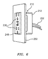
図6に、他の電力スイッチング装置の全体を参照符号210により示す。本装置210は図1〜図5との関連で上述した装置10,110とほぼ同様であるので、数字“2”が前置されている類似の参照符号を使用し、類似する要素を示すことにする。更に、本装置210については図示されていないが、本装置210の内部部材は装置10,110の内部部材とほぼ同一でよく、それらによる本装置210の制御及び作動も装置10,110とほぼ同じ形態でよい。それら内部部材をいわゆる当業者にはご理解頂けるであろう形態にて変形することで、装置10,110・本装置210間の違いを含め、本願記載の構造及び機能を本装置210に盛り込んでもよい。図1〜図5の電力スイッチング装置10,110と図6の電力スイッチング装置210との間の主たる違いは、壁250に設けられた壁開口248内に実装すること又はその壁開口248を貫き実装することができるように電力スイッチング装置210が構成されていて、外部に配置される“スタンドアロン”型の装置とは対照的なことに本装置210の一部分が壁250の後方に埋め込まれ又は延びていることである。図示実施形態では、本装置210が、一般的な壁面電力ソケット向けに使用される壁開口内にフィットするよう構成されている。好適なことに、これにより、本電力スイッチング装置210が不測の損傷から保護される。同じく好適なことに、本電力スイッチング装置210は壁から突出していないので、ユーザから見れば通常の電力アウトレットと同様である。電力アウトレットに例えばプラグ又はプロングにより接続しなければならない電力コネクタの使用時とは異なり、本電力スイッチング装置210には、壁250を貫き又はその内側を走る電気配線252との電気的接続を介し、建屋電力から直に電力が引き込まれている。図示実施形態では、電力スイッチング装置210が2個の電力レセプタクル236を有していて、それらが電力アウトレットでよくある形式にて上下配置されている。図1〜図5の実施形態との関連で上述した通り、これら電力レセプタクルそれぞれを、単一の内蔵電力スイッチで以て一括制御することも、個別制御することもできる。   In FIG. 6, the whole of another power switching device is indicated by reference numeral 210. Since the device 210 is substantially similar to the devices 10 and 110 described above in connection with FIGS. 1-5, use similar reference signs preceded by the numeral “2” to indicate similar elements. To. Further, although the apparatus 210 is not shown, the internal members of the apparatus 210 may be substantially the same as the internal members of the apparatuses 10 and 110, and the control and operation of the apparatus 210 by them are also substantially the same as the apparatuses 10 and 110. Form may be sufficient. By deforming these internal members in a form that can be understood by those skilled in the art, the structure and functions described in the present application may be incorporated into the apparatus 210, including differences between the apparatuses 10, 110 and the apparatus 210. . The main difference between the power switching devices 10, 110 of FIGS. 1 to 5 and the power switching device 210 of FIG. 6 is to be mounted in or through the wall opening 248 provided in the wall 250. In contrast to the “stand-alone” type device, where the power switching device 210 is configured so that it can be configured, a portion of the device 210 is embedded or extends behind the wall 250. It is that you are. In the illustrated embodiment, the device 210 is configured to fit within a wall opening used for a typical wall power socket. Advantageously, this protects the power switching device 210 from accidental damage. Also preferably, the power switching device 210 does not protrude from the wall and is similar to a normal power outlet from the user's perspective. Unlike the use of a power connector that must be connected to the power outlet, for example by a plug or prong, the power switching device 210 has an electrical connection with electrical wiring 252 that runs through or inside the wall 250, Electricity is drawn directly from the building power. In the illustrated embodiment, the power switching device 210 has two power receptacles 236 that are arranged one above the other in a form that is often the power outlet. As described above in connection with the embodiment of FIGS. 1-5, each of these power receptacles can be collectively controlled with a single built-in power switch or individually controlled.

いわゆる当業者にはご理解頂くべきことに、本電力スイッチング装置210は2個の電力レセプタクル236を有しているが、電力レセプタクルを何個有していてもよいし、全く有していなくてもよいし、それらがどのような好適又は所望構成を採っていてもよい。ある種の実施形態では、本装置210にて(図6に示した2ソケット構成以外の)既知壁面電力レセプタクル構成が採られる。既知レセプタクル構成を使用する成果の一つは、本装置210にて既知の又は標準的な電装箱、壁開口、壁板等々を利用できることである。これにより実装を簡略化することができ、カスタムの箱、板等々に関わるコスト増もない。それにより、壁内電装箱、壁開口、壁板等々を取り替えず既存の標準的な壁面レセプタクルを本装置210に置換すること、ひいては単純な部品“交換”で済ますことが可能にもなりうる。他の成果は、本装置210を既存の電気的壁面取付具に類する外観、ひいては美的に望ましい外観にしうることである。例えば、本装置210を、室内又は建屋内にある他の標準的な壁取付具に類する外観にするとよい。   It should be understood by those skilled in the art that the power switching device 210 has two power receptacles 236, but may have any number of power receptacles or none at all. They may take any suitable or desired configuration. In certain embodiments, the apparatus 210 employs a known wall power receptacle configuration (other than the two-socket configuration shown in FIG. 6). One outcome of using known receptacle configurations is that the device 210 can utilize known or standard electrical boxes, wall openings, wall plates, and so on. This simplifies the implementation and eliminates the cost associated with custom boxes, plates, etc. Accordingly, it may be possible to replace the existing standard wall receptacle with the present apparatus 210 without replacing the in-wall electrical box, wall opening, wall plate, and the like, and thus simply replace the component. Another outcome is that the device 210 can have an appearance similar to an existing electrical wall fixture, and thus an aesthetically desirable appearance. For example, the device 210 may have an appearance similar to other standard wall fixtures in a room or building.

図7に、他の電力スイッチング装置の全体を参照符号310により示す。本装置は図1〜図6との関連で上述した装置10、110及び210とほぼ同様であるので、数字“3”が前置されている類似の参照符号を使用し、類似する要素を示すことにする。更に、本装置310については図示されていないが、本装置310の内部部材は装置10,110,210の内部部材とほぼ同一でよく、それらによる本装置310の制御及び作動も装置10,110,210とほぼ同じ形態でよい。それら内部部材をいわゆる当業者にはご理解頂けるであろう形態にて変形することで、装置10,110,210・本装置310間の違いを含め、本願記載の構造及び機能を本装置210に盛り込んでもよい。図7の電力スイッチング装置と前掲の実施形態との間の主たる違いは以下の通りである。装置310は、硬質ケーシング素材製のハウジング312と、そのハウジング312の側面317,319から延びる支持部328とを有している。そのため、本装置をある面上に安置するに当たり、その面上のあらゆる潜在的有害物質例えば水に対し、装置310の内部部材が高い又は離れた位置に来る形態で、安置することができる。加えて、本電力スイッチング装置310は、その一端がハウジング312に固定されていて他端に電力コネクタ346がある給電コード332から電力を受け取る。電力コネクタ246から延びる電気配線(図示せず)がコード232内を通り、ハウジング312の開口(図示せず)を抜け、本装置312の内部部材に電気的に接続されているので、電力コネクタ246から装置210の構成部材に給電することができる。   In FIG. 7, the whole of another power switching apparatus is indicated by reference numeral 310. Since this apparatus is generally similar to apparatus 10, 110 and 210 described above in connection with FIGS. 1-6, like reference numerals preceded by the numeral “3” are used to indicate similar elements. I will decide. Further, although the device 310 is not shown, the internal members of the device 310 may be substantially the same as the internal members of the devices 10, 110, 210, and the control and operation of the device 310 by them are also the devices 10, 110, 210. The shape may be almost the same as 210. By deforming these internal members in a form that can be understood by those skilled in the art, the structure and functions described in this application are incorporated into the apparatus 210, including differences between the apparatuses 10, 110, 210 and the apparatus 310. But you can. The main differences between the power switching device of FIG. 7 and the previous embodiment are as follows. The apparatus 310 includes a housing 312 made of a hard casing material, and a support portion 328 extending from side surfaces 317 and 319 of the housing 312. Therefore, when the apparatus is placed on a certain surface, the inner member of the device 310 can be placed at a high or remote position with respect to any potentially harmful substances on the surface such as water. In addition, the power switching device 310 receives power from a power supply cord 332 having one end fixed to the housing 312 and the other end having a power connector 346. Since the electrical wiring (not shown) extending from the power connector 246 passes through the cord 232, passes through the opening (not shown) of the housing 312, and is electrically connected to the internal member of the apparatus 312, the power connector 246 Can supply power to the components of the apparatus 210.

図示実施形態では、電力コネクタ346が、電力ソケット(図示せず)につなげるのに適した電気プラグとされている。従って、本電力スイッチング装置310は、屋内及び屋外のいずれでも、壁面コンセント(図示せず)からある距離を隔て配置し、電気コード332を介しその壁面コンセントへと電気的に接続するのに適している。   In the illustrated embodiment, the power connector 346 is an electrical plug suitable for connection to a power socket (not shown). Therefore, the power switching device 310 is suitable for being placed at a distance from a wall outlet (not shown) both indoors and outdoors and electrically connected to the wall outlet via the electric cord 332. Yes.

いわゆる当業者にはご理解頂くべきことに、図7では電力コネクタ346がプラグであるが、電力コネクタ346は、電源に接続し給電コード332経由で本装置310に給電するのに適していれば、現在既知か今後開発されるかを問わずどのような構成でもよい。更に他種の実施形態に従い、本装置310に電気コネクタ346を設けず、給電コード332内配線を電源に直結例えば“ハードワイヤ”接続してもよい。同じくご理解頂くべきことに、給電コード332は、本装置310を電源例えば壁面ソケットに対し所望の位置に配置しうるよう、望みに応じどのような長さにもすることができる。   It should be understood by a so-called person skilled in the art that the power connector 346 is a plug in FIG. 7, but the power connector 346 is suitable for connecting to a power source and supplying power to the apparatus 310 via the power supply cord 332. Any configuration is possible regardless of whether it is currently known or will be developed in the future. Further, according to another type of embodiment, the electrical connector 346 may not be provided in the apparatus 310, and the wiring in the power supply cord 332 may be directly connected to a power source, for example, “hard wire” connection. It should also be appreciated that the feed cord 332 can be any length as desired so that the device 310 can be placed in a desired position relative to a power source, eg, a wall socket.

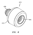
図8に、他の電力スイッチング装置の全体を参照符号410により示す。本装置は図1〜図7との関連で上述した装置10,110、210及び310とほぼ同様であるので、数字“4”が前置されている類似の参照符号を使用し、類似する要素を示すことにする。更に、本装置310については図示されていないが、本装置410の内部部材は装置10,110,210,310の内部部材とほぼ同一でよく、それらによる本装置410の制御及び作動も装置10,110,210,310とほぼ同じ形態でよい。それら内部部材をいわゆる当業者にはご理解頂けるであろう形態にて変形することで、装置10,110,210,310・本装置410間の違いを含め、本願記載の構造及び機能を本装置410に盛り込んでもよい。本実施形態では、本電力スイッチング装置410の内部部材(図示せず)が略円筒状のハウジング412内に収容されている。本装置410は、例えばランプその他の照明取付具に備わる電球用ソケット内に嵌めうるよう構成されている。電力コネクタ446は、電球用ソケット例えばエジソンソケット内にねじ込めるオス型電球キャップを備えている。電力コネクタ446としてねじ込み口金を有するそれを図示したが、いわゆる当業者にはご認識頂けるように、電力コネクタは、照明取付具例えばピン口金、差込口金、ウェッジ口金、モーガルプレフォーカス口金等々につなげうるものであれば、いわゆる当業者にとり既知のどのような形状にもすることができる。電力レセプタクル436は、メス型照明ソケット例えばエジソンソケットとして構成されている。従って、電力スイッチング装置410を照明取付具内に挿入例えば螺入し、電力レセプタクル436内に挿入されている電球その他の電気的装置に電力スイッチング装置410により給電することができよう。電力レセプタクル436としてねじ込み口金付電球を受入可能なそれを示したが、いわゆる当業者にはご認識頂けるように、本装置410は、例えばピン口金、差込口金、ウェッジ口金、モーガルプレフォーカス口金等々を初め、いわゆる当業者にとり既知などの口金を有する電球をつなげるようにも、構成することができる。同じくいわゆる当業者にはご理解頂くべきことに、照明取付具及び電球(又はソケット436に接続されている他の装置)を諸実施形態に従い稼働させるため使用される電圧は、現在使用されており又はいわゆる当業者にとり既知であるいずれの電圧でもよく、例えば120Vでも236Vでもよい。好適なことに、電力スイッチング装置310により、照明取付具からエネルギを引き込んでいる電球によるエネルギの消費を直接監視することができる。加えて、本電力スイッチング装置410は、図1〜図5に示した実施形態の如く壁又は壁面ソケットに配することも、図7に示した実施形態の如く給電コードを有するものにすることも必要でない。図示実施形態では、そのランプ又は取付具自体の給電コードにより本装置410に給電される。本実施形態では装置410の位置に関し付加的な柔軟性を提供することができ、例えば壁の位置ではなく例えば部屋の中央に装置410を配することができるので、本装置410の通信先となりうる遠隔装置との関係で本装置410をより選択的に例えばより好適に配置することができる。その種の実施形態によれば、状況にもよるが、図1〜図7の実施形態で以て達成されるであろうそれより多数の遠隔装置のレンジ内に本装置410が収まるようにすることができる。   In FIG. 8, the whole of another power switching apparatus is indicated by reference numeral 410. Since the apparatus is substantially similar to the apparatus 10, 110, 210 and 310 described above in connection with FIGS. 1-7, similar reference numerals are used and similar elements are preceded by the numeral “4”. Will be shown. Further, although the device 310 is not shown in the drawing, the internal members of the device 410 may be substantially the same as the internal members of the devices 10, 110, 210, 310, and the control and operation of the device 410 by them is also the device 10, 110, 210, 310 may be almost the same form. By modifying these internal members in a form that will be understood by those skilled in the art, the structure and functions described herein, including the differences between the apparatus 10, 110, 210, 310 and the apparatus 410, can be achieved. May be included. In the present embodiment, an internal member (not shown) of the power switching device 410 is accommodated in a substantially cylindrical housing 412. The device 410 is configured to fit into a light bulb socket provided in, for example, a lamp or other lighting fixture. The power connector 446 includes a male bulb cap that can be screwed into a bulb socket, such as an Edison socket. Although shown with a screw cap as the power connector 446, the power connector can be connected to a lighting fixture such as a pin cap, a plug cap, a wedge cap, a mogal prefocus cap, etc., as will be appreciated by those skilled in the art. Any shape known to those skilled in the art can be used. The power receptacle 436 is configured as a female lighting socket, such as an Edison socket. Accordingly, the power switching device 410 could be inserted, for example, screwed into the lighting fixture, and the power switching device 410 could power the bulb or other electrical device inserted in the power receptacle 436. Although shown as being able to accept a light bulb with a screw cap as the power receptacle 436, the device 410 can be used, for example, as a pin cap, a plug cap, a wedge cap, a mogal prefocus cap, etc. It can also be configured to connect a light bulb having a base as known to those skilled in the art. Also, it should be understood by those of ordinary skill in the art that the voltage used to operate the lighting fixture and light bulb (or other device connected to the socket 436) according to embodiments is currently used or Any voltage known to those skilled in the art may be used, for example 120V or 236V. Advantageously, the power switching device 310 allows direct monitoring of energy consumption by a light bulb that is drawing energy from the lighting fixture. In addition, the power switching device 410 may be arranged on a wall or wall socket as in the embodiment shown in FIGS. 1 to 5 or may have a power feeding cord as in the embodiment shown in FIG. Not necessary. In the illustrated embodiment, the apparatus 410 is powered by the power cord of the lamp or fixture itself. In this embodiment, additional flexibility can be provided regarding the position of the apparatus 410. For example, since the apparatus 410 can be arranged in the center of the room instead of the position of the wall, the apparatus 410 can be a communication destination. The apparatus 410 can be more selectively arranged, for example, more preferably in relation to the remote apparatus. According to such an embodiment, depending on the circumstances, the device 410 is within the range of more remote devices than would be achieved with the embodiment of FIGS. be able to.

図9〜図11に、本発明の電力スイッチング装置が採用されうる種々のシステムを模式的に示す。図示実施形態では、壁面コンセントに挿せる電力スイッチング装置10が示されている。しかしながら、本願記載の装置110、210、310及び410を含め、どのような好適構成の装置を図9〜図11のシステムにて利用してもよい。   9 to 11 schematically show various systems in which the power switching device of the present invention can be employed. In the illustrated embodiment, a power switching device 10 that can be inserted into a wall outlet is shown. However, any suitable configuration of devices, including the devices 110, 210, 310, and 410 described herein, may be utilized in the systems of FIGS.

図9〜図11に模式的に示すように、電力スイッチング装置10は、より詳細に後述する一種類又は複数種類の機能、例えば通信のブリッジング、装置の遠隔制御、装置の遠隔監視、遠隔装置及びシステムのアラーム状態条件の監視並びにデータ保存のため、システム又はIoTネットワークの一部として使用することができる。このシステムではそれらの機能を遠隔装置との関係で実行することができ、その遠隔装置を無線のみで電力スイッチング装置10にも被給電装置にも、例えば電力スイッチング装置10から電力を受け取るプラグイン型の装置例えば家電にも接続することができる。接続、監視又は制御されうる装置又は同システム内に格納されるデータを生成しうる装置の例としては、電力スイッチング装置10自体、サーモスタット、ドアロック、パーソナルセンサ例えば温度計、パーソナルロケータ、着座センサ、音響及びエンタテインメントシステム、子供用スリープモニタ、アラーム、調光又はモーション制御付の照明システム、環境モニタ並びにプラグイン家電がある。ご理解頂くべきことに、上掲のものは本発明のシステムに備わりうる装置についての幾つかの例に過ぎず、本発明はそれらの例により限定されず、且つ既存のものか今後開発されるものかを問わずいずれの装置も本発明で使用されうる。   As schematically shown in FIGS. 9 to 11, the power switching device 10 has one or more types of functions to be described in more detail later, such as communication bridging, device remote control, device remote monitoring, and remote device. And can be used as part of a system or IoT network for monitoring alarm conditions of the system and storing data. In this system, these functions can be executed in relation to a remote device, and the remote device can be connected to the power switching device 10 and the power-supplied device only by radio, for example, a plug-in type that receives power from the power switching device 10. It can be connected to other devices such as home appliances. Examples of devices that can be connected, monitored or controlled or that can generate data stored in the system include power switching device 10 itself, thermostat, door lock, personal sensors such as thermometers, personal locators, seating sensors, There are sound and entertainment systems, children sleep monitors, lighting systems with alarm, dimming or motion control, environmental monitors and plug-in appliances. It should be understood that the above are only some examples of devices that can be included in the system of the present invention, and the present invention is not limited by these examples, and the existing ones will be developed in the future. Any device, whether or not, can be used in the present invention.

ブリッジ機能については、図9に描出した実施形態に示す通り、電力スイッチング装置10を遠隔装置70・情報処理装置80間通信ブリッジ又はリレーとして働かせることができる。電力スイッチング装置10とペアリングされているいずれの遠隔装置からのコマンド又はテレメトリも、電力スイッチング装置10内ファームウェア(即ちマイクロコントローラ65内埋込コード)により変換し、続いてWiFi(登録商標)又はBluetooth(登録商標)等を介しIoT接続型情報処理装置へと送信することができるし、この逆も行うことができる。図9に示すように、遠隔装置70たる図中の無線温度計には、例えば、Bluetooth(登録商標)プロトコル71を使用し通信するためのBluetooth(登録商標)無線機が装備されている。遠隔装置70は情報例えば温度を電力スイッチング装置10へと送信する。電力スイッチング装置10には通信モジュールが装備されていて、その通信モジュールがBluetooth(登録商標)通信プロトコル71及びWiFi(登録商標)通信プロトコル73を使用し情報を送信しうるよう適合化されている。電力スイッチング装置10はBluetooth(登録商標)プロトコル71を媒介にして遠隔装置70から温度データを受信し、その情報をWiFi(登録商標)通信プロトコル73向けに変換する。   Regarding the bridge function, as shown in the embodiment depicted in FIG. 9, the power switching device 10 can be operated as a communication bridge or relay between the remote device 70 and the information processing device 80. Commands or telemetry from any remote device paired with the power switching device 10 is converted by the firmware in the power switching device 10 (ie, embedded code in the microcontroller 65), followed by WiFi (registered trademark) or Bluetooth. (Registered trademark) or the like can be transmitted to the IoT connection type information processing apparatus, and vice versa. As shown in FIG. 9, the wireless thermometer in the figure as the remote device 70 is equipped with, for example, a Bluetooth (registered trademark) radio device for communicating using the Bluetooth (registered trademark) protocol 71. The remote device 70 transmits information, such as temperature, to the power switching device 10. The power switching device 10 is equipped with a communication module, and the communication module is adapted to transmit information using the Bluetooth (registered trademark) communication protocol 71 and the WiFi (registered trademark) communication protocol 73. The power switching device 10 receives temperature data from the remote device 70 via the Bluetooth (registered trademark) protocol 71 and converts the information to the WiFi (registered trademark) communication protocol 73.

同じく図9に示すように、情報処理装置80は、ある通信経路を介し電力スイッチング装置10に可通信接続されている。図示実施形態では、その経路上に、電力スイッチ10を伴う無線通信モジュール(例.WiFi(登録商標))用のインタネットアクセスポイント又はラジオビーコン72、公衆インタネット(クラウド76により表されているそれ)との通信用のインターネットサービスプロバイダ(通信線74で表されているそれ)、並びにそのインターネットサービスプロバイダ74と同じものでも違うものでもよいがインタネットから情報処理装置80への通信を担うインターネットサービスプロバイダ(通信線78で表されているそれ)がある。情報処理装置80は、クラウド81で表されているIoTネットワーク内の他の装置にも接続することができる。   Similarly, as shown in FIG. 9, the information processing apparatus 80 is communicably connected to the power switching apparatus 10 via a certain communication path. In the illustrated embodiment, an internet access point or radio beacon 72 for a wireless communication module (e.g., WiFi) with a power switch 10 on its path, a public internet (that is represented by cloud 76), and Internet service provider for communication (the one represented by communication line 74), and the same or different Internet service provider 74, but the Internet service provider responsible for communication from the Internet to the information processing device 80 (communication There is that represented by line 78). The information processing apparatus 80 can be connected to other apparatuses in the IoT network represented by the cloud 81.

本システムは、情報処理装置80のユーザと対電力スイッチング装置10通信用の通信経路との間のインタフェース用の、実施形態によっては更に遠隔装置例えば遠隔装置70との間のインタフェース用の、コンピュータプログラム例えばアプリケーションを有するシステムにすることができる。ある種の実施形態に従い、そのコンピュータプログラムを情報処理装置80側アプリケーションとして格納してもよい。情報処理装置80側アプリケーションの例としては、遠隔装置の制御系例えば制御パネルを模すグラフィカルユーザインタフェース77を表示させるものがあろう。情報の受信又は送信に使用する情報処理装置80は、例えばスマートフォン、タブレット、モバイルコンピュータ、デスクトップコンピュータ等々、好適であればどのようなコンピュータ化デバイスであってもよい。   The system includes a computer program for an interface between a user of the information processing device 80 and a communication path for communication with the power switching device 10 and, in some embodiments, an interface with a remote device, such as the remote device 70. For example, it can be a system having an application. According to a certain embodiment, the computer program may be stored as the information processing apparatus 80 side application. An example of the application on the information processing apparatus 80 side is to display a graphical user interface 77 imitating a control system of a remote apparatus, for example, a control panel. The information processing apparatus 80 used for receiving or transmitting information may be any computerized device as long as it is suitable, such as a smartphone, a tablet, a mobile computer, a desktop computer, and the like.

この形態では、遠隔装置70が自遠隔装置70によるインタネットアクセスポイント72への情報送信を可能化する通信インタフェースを有していない場合でも、情報処理装置80にて遠隔装置70から情報を受け取ることができる。そのため、例えば、遠隔装置70にて、ほどほどの期待電池寿命を有する電池を利用することができる。   In this form, even when the remote device 70 does not have a communication interface that enables the remote device 70 to transmit information to the Internet access point 72, the information processing device 80 can receive information from the remote device 70. it can. Therefore, for example, the remote device 70 can use a battery having a reasonable expected battery life.

上掲の例では電力スイッチング装置10がBluetooth(登録商標)プロトコル・WiFi(登録商標)プロトコル間通信ブリッジとして動作するが、ご理解頂くべきことに、装置70及び80と電力スイッチング装置10との通信には、適するものであればどのような通信システム及びプロトコルを使用してもよい。例えば、遠隔装置70及び情報処理装置80をペアリングする通信ブリッジを、Bluetooth(登録商標)若しくはBluetooth(登録商標)ローエネルギ、赤外周波数、802.11周波数、超音波周波数、Zigbee(登録商標)周波数、ISM帯の無線測位スペクトラム周波数例えば420MHz〜450MHz及び902MHz〜928MHz、並びにGSM(登録商標)帯の無線周波数例えばGSM(登録商標)−450及びGSM(登録商標)−900のうち、一種類を使用するそれにすることができる。ある種の実施形態に従い、遠隔装置をアクセスポイント特権無しのWiFi(登録商標)プロトコルで稼働させてもよい。   In the above example, the power switching device 10 operates as a communication bridge between the Bluetooth (registered trademark) protocol and the WiFi (registered trademark) protocol. It should be understood that the communication between the devices 70 and 80 and the power switching device 10 is performed. Any suitable communication system and protocol may be used. For example, a communication bridge for pairing the remote device 70 and the information processing device 80 can be a Bluetooth (registered trademark) or Bluetooth (registered trademark) low energy, infrared frequency, 802.11 frequency, ultrasonic frequency, Zigbee (registered trademark). Frequency, ISM band radio positioning spectrum frequencies such as 420 MHz to 450 MHz and 902 MHz to 928 MHz, and GSM (registered trademark) band radio frequencies such as GSM (registered trademark) -450 and GSM (registered trademark) -900. You can do it to use. In accordance with certain embodiments, the remote device may be operated with the WiFi protocol without access point privileges.

同じく図9に示すように、ユーザは、遠隔装置70に向けた制御コマンドを、情報処理装置80からも、情報処理装置80に可通信接続されている他のいずれのIoTデバイス(図示せず)からも入力することができる。その通信文の入力に使用される手法は、キーパッド、タッチスクリーン又は音声コマンドを介するものを含め、いわゆる当業者にとり既知であり又は今後既知となりうるどのような手法にもすることができる。例えば、Apple Inc.により頒布されているHomeKit(登録商標)コマンドシステムが遠隔装置に装備されている場合、ユーザは、そのHomeKit(登録商標)システムに対し音声コマンドを発するだけで、電力スイッチング装置10及び遠隔装置70にコマンドを送ることができる。或いは、情報処理装置80を、その情報処理装置80に対する個別ユーザ入力無しで遠隔装置70を制御するプログラムを有するものにすることもできる。   Similarly, as shown in FIG. 9, the user can send a control command directed to the remote device 70 from the information processing device 80 to any other IoT device that is communicably connected to the information processing device 80 (not shown). Can also be entered. The technique used to input the message can be any technique known to the person skilled in the art or that may become known in the future, including via a keypad, touch screen or voice command. For example, Apple Inc. If the remote device is equipped with a HomeKit® command system distributed by the user, the user simply issues a voice command to the HomeKit® system, and the power switching device 10 and the remote device 70 are You can send commands. Alternatively, the information processing device 80 may have a program for controlling the remote device 70 without individual user input to the information processing device 80.

その通信文は次いで情報処理装置80からインタネット76を介しインタネットアクセスポイント72へと送られ、そこから例えばWiFi(登録商標)プロトコル73により電力スイッチング装置10へと送信される。電力スイッチング装置10は、次いでそのコマンドをBluetooth(登録商標)プロトコル71向けに変換して遠隔装置70へと送信する。このような形式で、Bluetooth(登録商標)対応遠隔装置70をインタネットを介し制御することができる。例えば、情報処理装置80により遠隔装置70にターンオン又はオフせよと指令することができる。また例えば、その遠隔装置がサーモスタットであり加熱又は除熱システムに可作動接続されている場合、ユーザは、その加熱/除熱システムを望み通り動作させるべくサーモスタットに指令することができる。ある種の実施形態に従い、遠隔装置70により通信経路経由で情報処理装置80へと情報が送信されるようにしてもよい。例えば、遠隔装置70により計測/検知された温度をその遠隔装置70から送信し、情報処理装置80がその情報に基づく動作をプログラムに従い採るようにしても、及び/又は、情報処理装置80がユーザにその情報例えば温度を通知するようにしてもよく、またその通知を、その情報処理装置80のグラフィカルユーザインタフェース77を介し行うようにしても、インタネット又は無線伝送(例えばWiFi又はBluetooth(登録商標))等を介する他情報処理装置(図示せず)への音声データ送信といった他の通信機構により行うようにしてもよい。   The communication text is then sent from the information processing device 80 to the Internet access point 72 via the Internet 76, and from there, for example, to the power switching device 10 by the WiFi (registered trademark) protocol 73. The power switching device 10 then converts the command for the Bluetooth (registered trademark) protocol 71 and transmits it to the remote device 70. In this way, the Bluetooth (registered trademark) compatible remote device 70 can be controlled via the Internet. For example, the information processing device 80 can instruct the remote device 70 to turn on or off. Also, for example, if the remote device is a thermostat and is operatively connected to a heating or heat removal system, the user can command the thermostat to operate the heating / heat removal system as desired. Information may be transmitted by remote device 70 to information processing device 80 via a communication path in accordance with certain embodiments. For example, the temperature measured / detected by the remote device 70 may be transmitted from the remote device 70, and the information processing device 80 may take an operation based on the information according to the program, and / or the information processing device 80 may be a user. The information, for example, the temperature may be notified, or the notification may be made via the graphical user interface 77 of the information processing apparatus 80, or the Internet or wireless transmission (for example, WiFi or Bluetooth (registered trademark)). ) Etc. may be performed by another communication mechanism such as voice data transmission to another information processing apparatus (not shown).

他の例としては“スマート”ドアロックとの遠隔通信に関連するものがある。スマートドアロックには電池から給電を受けるものが多々あるが、これは、建屋給電系からドアロックへの電気的配線が多くのドアデザインで実用的でないか、或いは特に改造利用に当たり高コストになるためである。電力を節約するため、スマートロックには往々にしてBluetooth(登録商標)又はBluetooth(登録商標)ローエネルギ通信無線機しか装備されない。本発明のシステムでは、ユーザが情報処理装置80側アプリケーションを使用し通信文、例えばスマートドアロックを制御しそのドアをロック又はアンロック等するためのコマンドを入力することができる。そのコマンドは次いでインタネット76及びアクセスポイント72を介し電力スイッチング装置10へと送信される。電力スイッチング装置10は、次いでその通信文をBluetooth(登録商標)又はBluetooth(登録商標)ローエネルギプロトコル向けに変換し、スマートドアロックへと送信する。次いで、スマートドアロックがその通信文に反応し例えばドアをアンロックさせる。ある種の実施形態によれば、そのスマートドアロックにより、次いで、Bluetooth(登録商標)を介し電力スイッチング装置10へと情報(例.ロックされたかアンロックされたかといったドアロックの状態)を逆送信することができる。その情報が電力スイッチング装置10により例えばWiFi(登録商標)プロトコル向けの変換を経てインタネットアクセスポイント72へと送信され、インタネットを介し情報処理装置80へと逆送されることで、例えばそのユーザが望んでいる動作が完遂されたことの確認となる。   Another example is related to remote communication with “smart” door locks. Many smart door locks are powered by batteries, but this is because the electrical wiring from the building power supply system to the door lock is not practical for many door designs, or is especially expensive for retrofitting Because. To save power, smart locks are often only equipped with Bluetooth® or Bluetooth® low energy communication radios. In the system of the present invention, a user can input a command for controlling a communication sentence, for example, a smart door lock and locking or unlocking the door, using an application on the information processing apparatus 80 side. The command is then transmitted to the power switching device 10 via the Internet 76 and the access point 72. The power switching device 10 then converts the communication text for the Bluetooth (registered trademark) or the Bluetooth (registered trademark) low energy protocol and transmits it to the smart door lock. The smart door lock then reacts to the message and unlocks the door, for example. According to certain embodiments, the smart door lock then back-transmits information (eg, door lock status, such as locked or unlocked) to the power switching device 10 via Bluetooth®. can do. The information is transmitted to the Internet access point 72 through the conversion for the WiFi (registered trademark) protocol, for example, by the power switching device 10 and is sent back to the information processing device 80 via the Internet. It is a confirmation that the running operation has been completed.

本システムにて、電力スイッチング装置10を利用し、その電力スイッチング装置10に電気的に接続されている被給電装置79の動作を遠隔制御してもよい。図示実施形態では被給電装置79が電子レンジとして表されている。しかしながら、上述の通り、被給電装置79は既知の又は既知となりうるどのような電力作動型装置であってもよい。   In this system, the power switching device 10 may be used to remotely control the operation of the power-supplied device 79 that is electrically connected to the power switching device 10. In the illustrated embodiment, the power-supplied device 79 is represented as a microwave oven. However, as described above, the power-supplied device 79 may be any power-operated device that is known or can be known.

ある種の実施形態によれば、IoT環境内で実行されるアプリケーションにてセンサ(図示せず)からのデータを使用することで、事前選択値に基づき被給電装置79の接続状態をオンからオフへ又はその逆へと変化させることができる。これは、情報処理装置80へのユーザ入力を介し直接的に実行してもよいし、プリセット時間その他の制限をプログラミングしておきそれを使用することによって実行してもよい。それらセンサは、電力スイッチ10内ブリッジ機能を媒介にIoTに接続してもよいし、他の電力スイッチブリッジを介し接続させても他の手段によりIoTに接続させてもよい。それらセンサは例えば熱センサ又はモーションセンサとすることができる。いわゆる当業者にはご理解頂くべきことに、その熱センサ又はモーションセンサには、それらセンサにより所与時間後にエリア内で人物が検出されなかった場合に情報処理装置80に信号を送るよう、プログラミングすることができる。或いは、その検知エリア内に人がいるとの信号をペアリングその他可通信接続されているセンサからある時間例えばプリセット時間以内に受信しなかった場合にそのエリア内に人がいないと結論づけるよう、情報処理装置80にプログラミングしてもよい。情報処理装置80はそれを受け電力スイッチング装置10に信号を送ることで、電力スイッチング装置10に電気的に又は無線により接続されている照明をターンオフさせることができる。同じ要領で、温度が所与値を超え上昇したら屋根裏換気扇をターンオフさせ、温度が設定ポイントよりも下がったらターンオフさせるよう、本システムにプログラミングしてもよい。それらセンサにより収集されたデータは、情報処理装置80内に格納する等、IoTに接続されていてそうした格納が可能であるどのような装置内に格納してもよい。本システムでは、電力使用に関連するデータ及び接続先電力装置の状態例えばオン/オフに関連するデータ等を含め、様々な他種データをも、IoTに接続されていてそうした格納が可能なあらゆる装置内に格納させうる。   According to certain embodiments, using data from a sensor (not shown) in an application running within the IoT environment, the connection state of the powered device 79 is switched from on to off based on a preselected value. Or vice versa. This may be performed directly through user input to the information processing device 80, or may be performed by programming a preset time and other restrictions and using them. These sensors may be connected to the IoT through the bridge function in the power switch 10, or may be connected to the IoT through other power switch bridges or by other means. These sensors can be, for example, thermal sensors or motion sensors. Those skilled in the art should understand that the thermal or motion sensor is programmed to send a signal to the information processing device 80 if no person is detected in the area after a given time by the sensors. be able to. Alternatively, if the signal indicating that there is a person in the detection area is not received within a certain time, for example, within a preset time, from a paired or other sensor that is communicably connected, information can be concluded to conclude that there is no person in the area. The processing device 80 may be programmed. The information processing device 80 receives the signal and sends a signal to the power switching device 10 to turn off the lighting connected to the power switching device 10 electrically or wirelessly. In the same manner, the system may be programmed to turn off the attic fan when the temperature rises above a given value and turn off when the temperature drops below the set point. Data collected by these sensors may be stored in any device that is connected to the IoT and capable of such storage, such as storing in the information processing device 80. In this system, any device that can store various other types of data, including data related to power usage and the status of connected power devices such as data related to on / off, etc., connected to the IoT Can be stored inside.

上述の通り、電力スイッチング装置10があるエリア内例えばある部屋の中に配置されているときには、その電力スイッチング装置の無線レンジ内にあるどの装置も、或いはその電力スイッチから電力を受け取っているどの被給電装置も、データ格納が可能な1個又は複数個の装置にその電力スイッチング装置10を介して無線接続することができる。この格納により、内部記憶ストレージを欠く装置により生成されたデータを記録することが可能となり、或いは複数個の装置からのデータを例えばユーザによるアクセスに備え格納するための統合的な場所を提供することができる。例えば、被給電装置79例えばランプでの電力使用を、クラウド81上に本拠を置く記憶ストレージに記録させ格納するとよい。加えて、そのデータは、例えば情報処理装置80や電力スイッチング装置10を含め、IoTネットワークに接続されているいずれの装置に格納してもよい。そうした電力使用の監視結果は、いわゆる当業者にとり既知のあらゆる方法、例えば上掲の如き電力スイッチング装置10内の統合型電流モニタにより得ることができる。加えて、集中使用又は制御アプリケーションやインタネットアクセスポイントへの接続が容易でない装置、例えば無線通信能力を欠く被給電装置79に関するデータを収集及び格納するとよい。好適なことに、このデータは、電話その他の情報処理装置が遠隔装置70又は被給電装置79に直にペアリングされていない場合でも、例えば装置10内にある電力計測回路その他の検知部材により、遠隔装置70又は被給電装置79から収集することができる。その後は、コンピュータ、電話機、タブレットその他のスマートデバイス上で実行されるアプリケーションにより、そのデータにアクセスすること並びにIoT電力スイッチを介し接続されている装置を制御することができる。   As described above, when the power switching device 10 is placed in an area, for example, in a room, any device within the radio range of the power switching device or any device receiving power from the power switch. The power feeding device can also be wirelessly connected to one or a plurality of devices capable of storing data via the power switching device 10. This storage makes it possible to record data generated by devices lacking internal storage, or to provide an integrated location for storing data from multiple devices, eg for user access. Can do. For example, the power usage of the power-supplied device 79 such as a lamp may be recorded and stored in a storage storage based on the cloud 81. In addition, the data may be stored in any device connected to the IoT network including the information processing device 80 and the power switching device 10, for example. Such power usage monitoring results can be obtained by any method known to those skilled in the art, such as an integrated current monitor in the power switching device 10 as described above. In addition, data relating to devices that are not easy to use centrally or connected to control applications or Internet access points, such as powered devices 79 lacking wireless communication capability, may be collected and stored. Preferably, this data may be captured by, for example, a power metering circuit or other sensing member within the device 10 even when the telephone or other information processing device is not directly paired with the remote device 70 or the powered device 79. It can be collected from the remote device 70 or the powered device 79. Thereafter, an application running on a computer, phone, tablet or other smart device can access the data and control the devices connected via the IoT power switch.

同様の形式にて、本システムをアラーム条件の検出及びそれに関するメッセージの生成に使用してもよい。アラーム条件を検出及び警報するためのアプリケーションは、本システム内のどのような好適装置、例えば電力スイッチング装置10、情報処理装置80又はクラウド81に属する装置に格納しその装置上で実行してもよい。注記すべきことに、このアプリケーションを、そのアラーム状態が監視されている装置上に格納する必要はない。アラーム条件は、正常状態からの重大な乖離たるあらゆる事態により組成されうる。アラーム条件の例としては、電力スイッチング装置10に流れる電流が所定値を超え急上昇(サージ)したこと、被給電装置79例えばランプ又はサーモスタットからの電力が切断されたこと等がある。そうしたアラーム条件は例えば停電又は電力過負荷により引き起こされうる。アラーム条件としては遠隔装置70の状況に関係するもの、例えば電力スイッチング装置10・遠隔装置70間遠隔通信が切断された、といったものもある。アラーム条件としては、遠隔装置70によって検出される環境条件に関係するものもある。例えば、遠隔装置70が地下室内水検出器であり、水漏れを検出しうるよう構成されているものとする。遠隔装置70により、こうしたアラーム状態についての情報を、例えば給電を受けているスイッチング装置10を介し、本システムに接続されている他の装置又は情報処理装置80へと上述の如く送信することができる。この形態により、遠隔装置70を、電池切れなく長期間に亘り信頼性よく動作させることができる。これは、アクセスして電池の交換又は充電を行うことが容易でない場所に遠隔装置70が所在している場合に、特に有益である。   In a similar manner, the system may be used to detect alarm conditions and generate messages related thereto. The application for detecting and alarming the alarm condition may be stored in and executed on any suitable device in the system, for example, the power switching device 10, the information processing device 80, or a device belonging to the cloud 81. . It should be noted that this application need not be stored on the device whose alarm condition is being monitored. An alarm condition can be composed of any event that is a significant departure from the normal state. Examples of alarm conditions include that the current flowing through the power switching device 10 has exceeded a predetermined value and has suddenly increased (surge), and that power from a power-supplied device 79 such as a lamp or thermostat has been cut off. Such an alarm condition can be caused, for example, by a power outage or power overload. There are alarm conditions related to the status of the remote device 70, for example, the remote communication between the power switching device 10 and the remote device 70 is disconnected. Some alarm conditions relate to environmental conditions detected by the remote device 70. For example, it is assumed that the remote device 70 is an underground water detector and is configured to detect a water leak. The remote device 70 can transmit information about such an alarm state to, for example, another device connected to the present system or the information processing device 80 via the switching device 10 that is receiving power as described above. . With this configuration, the remote device 70 can be reliably operated over a long period of time without running out of the battery. This is particularly beneficial if the remote device 70 is located where it is not easy to access and replace or charge the battery.

本システムにて、いわゆる当業者にとり既知な何らかの手段を利用し、アラーム条件をユーザに通知してもよい。そうした手段としては、例えば、情報処理装置80からの音響出力、電力スイッチング装置10のステータスモニタからの光信号の送信、或いはユーザの携帯電話へのショートメッセージサービス(SMS)メッセージの配信があろう。更に、アラーム条件の発生に応じ特定の制御機能を実行するよう、本システムにプログラミングしてもよい。例えば、被給電装置79に対し異常な大電流が供給されたときに、本システムにより、被給電装置79への電力をシャットオフするよう電力スイッチング装置10に指令することができる。   In this system, the alarm condition may be notified to the user by using any means known to those skilled in the art. Such means may be, for example, acoustic output from the information processing device 80, transmission of an optical signal from the status monitor of the power switching device 10, or delivery of a short message service (SMS) message to the user's mobile phone. Furthermore, the system may be programmed to perform specific control functions in response to the occurrence of alarm conditions. For example, when an abnormal large current is supplied to the power supplied device 79, the present system can instruct the power switching device 10 to shut off the power to the power supplied device 79.

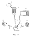
図10に、電力スイッチング装置10が複数個の装置70,82及び情報処理装置80に可通信接続されているシステムの一例を示す。ある種の実施形態では、装置70,82が同一通信プロトコルを使用し動作させうる装置、例えば共にBluetooth(登録商標)対応の装置とされることがある。だが、その種の実施形態では、装置70,82の位置が互いに遠く離れすぎていて直接に通信できないことがありうる。その場合でも、例えばBluetooth(登録商標)プロトコル71を介し両装置70,82を電力スイッチング装置10と通信させることができる。こうすることで、その電力スイッチング装置10を、アクセサリ装置70,82向けの送受信機又は基地局として実質的に働かせることができる。そのため、電力スイッチング装置10のレンジ内にあるアクセサリ装置70,82を装置10により制御し、監視し及び/又はそれらからデータを受信することができる。   FIG. 10 shows an example of a system in which the power switching device 10 is communicably connected to a plurality of devices 70 and 82 and the information processing device 80. In certain embodiments, the devices 70 and 82 may be devices that can operate using the same communication protocol, eg, both Bluetooth-compatible devices. However, in such an embodiment, the devices 70, 82 may be too far apart to communicate directly. Even in such a case, both devices 70 and 82 can communicate with the power switching device 10 via, for example, the Bluetooth (registered trademark) protocol 71. By doing so, the power switching device 10 can be substantially operated as a transceiver or base station for the accessory devices 70 and 82. As such, accessory devices 70 and 82 within the range of power switching device 10 can be controlled by device 10 and monitored and / or data received therefrom.

他種実施形態では、それらが互いのレンジ内に存していても直接に通信しないよう、装置70,82にて別々の又は非コンパチブルな通信プロトコルが利用される。こうした実施形態でも、電力スイッチング装置10にそれら別々の通信プロトコル間の変換を行わせることにより、図9との関連で上述した如く電力スイッチング装置10を装置70,82間ブリッジとして働かせることができる。ある種の実施形態に従い、電力スイッチング装置10により、装置70及び装置82と情報処理装置80との間で情報を通信させてもよい。図示実施形態では、電力スイッチング装置10がBluetooth(登録商標)プロトコル71からの情報を変換し、WiFi(登録商標)プロトコル73を使用し情報処理装置80と通信している。これとは違い、装置70及び82のそれと同一の通信プロトコルを使用し電力スイッチング装置が情報処理装置80と通信するようにしてもよいので、例えば、装置70及び82が共にBluetooth(登録商標)又はBLEプロトコルを使用する一方で、装置10のBluetooth(登録商標)/BLEレンジ内にある情報処理装置80がその装置10とペアリングされるようにしてもよい。ある種の実施形態では、例えば、ユーザにより要求された場合にのみ、或いはユーザが情報処理装置80を電力スイッチング装置10内接近センサのレンジ内に持ち込んだ場合にのみ、電力スイッチング装置10により情報処理装置80へと情報が送信される。その種の実施形態のうちあるものによれば、装置10のBluetooth(登録商標)/BLEレンジ内へ又は外へと情報処理装置80が移動したときに、装置10にてプロトコルをBluetooth(登録商標)/BLE・WiFi(登録商標)間で切り替えることができる。   In other embodiments, separate or non-compatible communication protocols are utilized in the devices 70, 82 so that they do not communicate directly even if they are in range of each other. Even in such an embodiment, by allowing the power switching device 10 to convert between these separate communication protocols, the power switching device 10 can act as a bridge between the devices 70 and 82 as described above in connection with FIG. In accordance with certain embodiments, the power switching device 10 may cause information to be communicated between the devices 70 and 82 and the information processing device 80. In the illustrated embodiment, the power switching device 10 converts information from the Bluetooth (registered trademark) protocol 71 and communicates with the information processing device 80 using the WiFi (registered trademark) protocol 73. Unlike this, the power switching device may communicate with the information processing device 80 using the same communication protocol as that of the devices 70 and 82. For example, both the devices 70 and 82 are Bluetooth (registered trademark) or While using the BLE protocol, the information processing device 80 within the Bluetooth (registered trademark) / BLE range of the device 10 may be paired with the device 10. In certain embodiments, for example, only when requested by the user or when the user brings the information processing device 80 into the range of the proximity sensor in the power switching device 10, the information processing by the power switching device 10 is performed. Information is transmitted to the device 80. According to some such embodiments, when the information processing device 80 moves into or out of the Bluetooth® / BLE range of the device 10, the device 10 uses the Bluetooth® protocol. ) / BLE / WiFi (registered trademark).

従って、本発明によれば、例えばそれらを隔てる物理的距離や非コンパチブルなプロトコル故に互いに通信できないはずの装置70,82間での通信が可能となる。加えて、装置70,82のうち1個又は複数個を情報処理装置80により監視すること及び/又は情報処理装置80を使用し制御することができる。   Therefore, according to the present invention, communication between devices 70 and 82 that should not be able to communicate with each other due to a physical distance separating them or a non-compatible protocol is possible. In addition, one or more of the devices 70 and 82 can be monitored and / or controlled using the information processing device 80.

例えば、図10に示す実施形態では、電力スイッチング装置10により無線温度計70・ワイヤレスパワーキューブ82間通信リンクが提供されている。装置82に加熱/除熱ユニットが挿されている場合には、温度計70が電力スイッチング装置10を介し装置82へと温度信号を送り、通知された温度に基づき装置82が加熱/除熱ユニットを作動させることで、その加熱/除熱ユニットの所在場所における温度を制御することができる。他種実施形態に従い、温度計70により電力スイッチング装置10を介し情報処理装置80へと温度計測結果を送信してもよいし、プラグ82により電力スイッチング装置10を介し情報処理装置80へと加熱/除熱ユニット82についての情報、例えば電力状態(オン/オフ)、エネルギ使用、動作時間等々を送信してもよい。更に他種の実施形態に従い、情報処理装置80により、電力スイッチング装置10を介し装置70,82のうち1個又は複数個へとコマンド命令を送信してもよい。これは、例えば上述した理由によって装置70、装置82及び/又は情報処理装置80が互いに直接に通信していない(ある種の実施形態では通信できない)場合でも行える。   For example, in the embodiment shown in FIG. 10, a communication link between the wireless thermometer 70 and the wireless power cube 82 is provided by the power switching device 10. When a heating / heat removal unit is inserted in the device 82, the thermometer 70 sends a temperature signal to the device 82 via the power switching device 10, and the device 82 is heated / heat removal unit based on the notified temperature. , The temperature at the location of the heating / heat removal unit can be controlled. According to another embodiment, the temperature measurement result may be transmitted to the information processing device 80 via the power switching device 10 by the thermometer 70, or the heating / heating to the information processing device 80 via the power switching device 10 by the plug 82. Information about the heat removal unit 82, such as power status (on / off), energy usage, operating time, etc. may be transmitted. Further, according to another type of embodiment, the information processing apparatus 80 may transmit a command command to one or a plurality of apparatuses 70 and 82 via the power switching apparatus 10. This can be done even if, for example, the device 70, device 82 and / or information processing device 80 are not in direct communication with each other (cannot communicate in certain embodiments).

図10には電力スイッチ10に可通信接続された装置が2個しか示されていないが、電力スイッチング装置10を、自電力スイッチング装置10の通信レンジ内にある所望の多さの装置をブリッジングしうるよう使用及び構成することができる。即ち、ユーザは、電力スイッチング装置10を介し多数のアクセサリ装置例えばライト又はランプを可通信接続させることができ、また電力スイッチング装置10を介した可通信接続により、電力スイッチング装置10に可通信接続されているライト全て又はその一部を制御させること(例.ターンオン又はオフさせること)ができる。好適なことに、この能力があるので、ユーザは、各アクセサリ装置に個別接続するのではなく単一の装置即ち電力スイッチング装置10に自分の情報処理装置80を接続するだけでよい。これは、特に、種々のホームオートメーション装置例えばプラグ及び/又はアウトレット、壁面スイッチ、テーブルタップ、ランプ、サーモスタット、ガレージドアオープナ、ドアロック及び家電がセットアップされている“接続型”家庭では有益なことである。注記すべきことに、図10の実施形態では情報処理装置80が電力スイッチング装置10に直接接続されているが、他種実施形態によれば、情報処理装置80をプラグに間接経路経由で、例えばインタネット、ローカルイントラネット、仲介スマートプラグ(群)又は他の通信システムを経由し接続することができる。   FIG. 10 shows only two devices communicably connected to the power switch 10, but the power switching device 10 is bridged with a desired number of devices within the communication range of the own power switching device 10. Can be used and configured. That is, the user can connect a number of accessory devices such as lights or lamps via the power switching device 10 via a communicable connection, and can be communicably connected to the power switching device 10 via a communicable connection via the power switching device 10. It is possible to control (eg turn on or off) all or part of the light that is on. Preferably, because of this capability, the user need only connect his information processing device 80 to a single device or power switching device 10, rather than individually connecting to each accessory device. This is particularly beneficial in “connected” homes where various home automation devices such as plugs and / or outlets, wall switches, table taps, lamps, thermostats, garage door openers, door locks and appliances are set up. is there. It should be noted that in the embodiment of FIG. 10, the information processing device 80 is directly connected to the power switching device 10, but according to other embodiments, the information processing device 80 is connected to a plug via an indirect path, for example, Connections can be made via the Internet, local intranet, intermediary smart plug (s) or other communication systems.

加えて、電力スイッチング装置10が、自電力スイッチング装置10のレンジ内にある所望の多さの装置間でコヒーシブ通信(即ち直接的、統合的且つシームレスな通信)を行えるようにするファームウェアを、有していてもよい。更に、そのファームウェアを、そうしたコヒーシブ通信を複数担いうるよう適合化させてもよい。ある種の実施形態では、そのファームウェアにより、同数の装置・コントローラ対を相手とする多数の通信であり、各通信が別々の装置を相手とするそれが担われる。そのファームウェアにより、各装置・コントローラ対間の通信をブリッジさせてもよい。ある種の実施形態では、そうした多数の装置全てが同一のプロトコルを使用し通信する。例えば、多数のBluetooth(登録商標)接続デバイス(図示せず)を、電力スイッチング装置10を通信ブリッジとして使用し同期させ及び制御するとよい。その種の実施形態によれば、別々の対IoTネットワーク通信プロトコル又は接続を利用することなく、相互のやりとりを通じ多数の遠隔装置を制御することができる。   In addition, there is firmware that allows the power switching device 10 to perform coherent communication (ie, direct, integrated and seamless communication) between a desired number of devices within the range of the self-power switching device 10. You may do it. Furthermore, the firmware may be adapted to carry multiple such coherent communications. In some embodiments, the firmware is responsible for multiple communications with the same number of device / controller pairs, each communication being handled by a separate device. Communication between each device / controller pair may be bridged by the firmware. In certain embodiments, many such devices all communicate using the same protocol. For example, a number of Bluetooth® connected devices (not shown) may be synchronized and controlled using the power switching device 10 as a communication bridge. According to such an embodiment, multiple remote devices can be controlled through interaction with each other without using a separate IoT network communication protocol or connection.

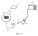
図11に、システムの他実施形態として、例えば電力スイッチング装置10を使用し装置例えばBluetooth(登録商標)対応家電をリモートコンピュータシステム84に可作動接続すること及び/又はそれら装置をリモートコンピュータシステム84で以て制御することができるものを示す。図9及び図10に示したように、例えば、電力スイッチング装置10により、1個又は複数個の装置(図11には示さず)からデータを受信することができる。次いで、電力スイッチング装置10が、無線通信例えばWiFi(登録商標)プロトコル73を介しリモートコンピュータ84と通信する。この通信は、種々のウェイポイント例えばWiFi(登録商標)アクセスポイント72、インターネットサービスプロバイダ74及び公衆インタネット76を介して実行されよう。ある種の実施形態によれば、ユーザが、例えばインタネット及びWiFi(登録商標)通信を使用しリモートコンピュータ84から電源プラグ10へと情報又はコマンドを送ることができる。   FIG. 11 shows another embodiment of the system in which, for example, the power switching device 10 is used to operably connect a device such as a Bluetooth-compatible home appliance to the remote computer system 84 and / or the device in the remote computer system 84. This indicates what can be controlled. As shown in FIGS. 9 and 10, for example, the power switching device 10 can receive data from one or more devices (not shown in FIG. 11). Next, the power switching device 10 communicates with the remote computer 84 via wireless communication, for example, WiFi (registered trademark) protocol 73. This communication may be performed via various waypoints such as WiFi® access point 72, Internet service provider 74 and public internet 76. According to certain embodiments, a user can send information or commands from the remote computer 84 to the power plug 10 using, for example, the Internet and WiFi communication.

こうしてリモートコンピュータ84へと転送されたデータは、いわゆる当業者にはご理解頂くべきあらゆる好適な目的で使用されうる。例えば、電力スイッチング装置10から受信した電気使用データをリモートコンピュータ84にて格納及び分析するとよい。この使用データは、例えば、電力スイッチング装置10に挿されている家電79がターンオン又はオフされた日内時刻、1回又は複数回の“オン”期間中にその家電により引き込まれた電流の量、即ちエネルギ消費に対応する量、並びに家電79による電力使用のピーク時刻で構成されうる。リモートコンピュータ84が、このデータを分析して実行所要動作を決定するプログラム、例えば総消費電力の低減、ユーザの安楽等々を初め一通り又は複数通りの望ましい目標を達成する上で最も有利な空調ターンオンタイミングを決定するプログラムを、有していてもよい。リモートコンピュータ84が、その家電から受信した情報以外の情報、例えば本システム又はクラウド(図10には示さず)に接続されている他の情報処理装置から受信した情報を踏まえ、制御命令を生成するようにしてもよい。例えば、その空調装置による過去の電力消費、外気温、並びに送配電網全体での電力使用状況の各者に基づき、リモートコンピュータが、空調装置を動作させるのに最も有利なタイミングを決定すればよい。   The data thus transferred to the remote computer 84 can be used for any suitable purpose that should be understood by those skilled in the art. For example, electricity usage data received from the power switching device 10 may be stored and analyzed by the remote computer 84. This usage data includes, for example, the time of day when the home appliance 79 inserted in the power switching device 10 is turned on or off, the amount of current drawn by the home appliance during one or more “on” periods, ie, An amount corresponding to energy consumption, and a peak time of power use by the home appliance 79 can be configured. The remote computer 84 analyzes the data to determine the action required for execution, such as reducing the total power consumption, user comfort, etc. The air conditioning turn-on that is most advantageous in achieving one or more desired goals. You may have the program which determines a timing. The remote computer 84 generates a control command based on information other than the information received from the home appliance, for example, information received from another information processing apparatus connected to the system or the cloud (not shown in FIG. 10). You may do it. For example, the remote computer may determine the most advantageous timing for operating the air conditioner based on each of the past power consumption by the air conditioner, the outside air temperature, and the power usage status of the entire transmission and distribution network. .

上述した機能それぞれについて言えば、それら機能を実行するためのプログラムを単一の装置上に駐在させてもよいし、IoTネットワークに接続されている複数個の装置上に駐在させてもよい。即ち、電力スイッチング装置10上、遠隔装置70内、情報処理装置80内、クラウド81内及び/又はIoTネットワーク内にあり相応な格納能力が装備されている他のあらゆる装置内に、プログラム、アプリケーション又はデータを駐在させ又は格納することができる。それらの例としては、例えば、上述したリモート格納データ、制御アプリケーション、プログラマブルなアラーム状態条件及びワーニング、データ格納アプリケーション、データ監視アプリケーション、並びに装置間コヒーシブ通信を可能化するファームウェアがある。例えば、上述の通り、電力レセプタクル36に流れる電流が所定値を上回ったらいつでもアラーム信号を生成するよう、電力スイッチング装置10にプログラミングするとよい。このプログラムは、電力スイッチング装置上のファームウェアとして例えばマイクロコントローラ65上に排他格納するとよい。これに代え、プラグにより計測された電流の変化に応答するよう適合化されているアラームプログラムの諸部分を、遠隔装置70上、情報処理装置80上、或いはIoTシステムに接続されているいずれかの装置上に格納することができる。   With regard to each of the functions described above, a program for executing these functions may be resident on a single device, or may be resident on a plurality of devices connected to the IoT network. That is, on the power switching device 10, in the remote device 70, in the information processing device 80, in the cloud 81 and / or in any other device equipped with the appropriate storage capability in the IoT network, Data can be stationed or stored. Examples include remote storage data, control applications, programmable alarm state conditions and warnings described above, data storage applications, data monitoring applications, and firmware that enables inter-device coherent communication. For example, as described above, the power switching device 10 may be programmed to generate an alarm signal whenever the current flowing through the power receptacle 36 exceeds a predetermined value. This program is preferably stored exclusively on the microcontroller 65 as firmware on the power switching device. Alternatively, portions of the alarm program that are adapted to respond to changes in the current measured by the plug, either on the remote device 70, on the information processing device 80, or connected to the IoT system It can be stored on the device.

加えて、図9〜図11には電力スイッチング装置10・遠隔装置70間無線接続を示したが、上述した機能それぞれを有線接続を媒介にして実現すること、例えばUSBケーブルによるUSB接続を介した電力スイッチング装置10とUSB対応装置の通信で実現することができる。上述の通り、電力スイッチング装置10が、自電力スイッチング装置10のハウジング12の開口29を介しアクセス可能なUSBポートを有していてもよい。このUSB接続を利用し、USBデバイスの制御、監視又はそれへのデータ転送を行うとよい。更に、電力スイッチング装置10に複数個のUSBポートを具備させることで、複数個のUSBデバイスをそれに接続可能にし、例えば情報処理装置80又はクラウド81内装置により電力スイッチング装置10の通信部材を介しそれらUSBデバイスを遠隔監視及び/又は無線制御できるようにしてもよい。同様に、それらUSBデバイスから得られたデータ又はそれらUSBデバイスに関連付けられているデータは、電力スイッチング装置10のマイクロコントローラ65のオンボードメモリ上、“ローカル”なUSBデバイス例えばデスクトップコンピュータ内、ローカルネットワーク又はクラウド上の装置内、或いは装置10の通信ブリッジを介しそのUSBデバイスに接続可能である他のいずれの装置内に、格納してもよい。同様に、被給電装置79及び遠隔装置70,82との関連で上述した通り、本システムがUSBデバイス向け制御アプリケーションを有していてもよいし、その通信が無線ではなくUSBケーブルを介している点で違いはあるが、無線接続されている装置との関連で上述したそれに類する要領で接続先USBデバイスに関しアラーム状態条件及びワーニングを検出及び発令するプログラムを、本システムが有していてもよい。更に、上述の通り、それらアプリケーション及びプログラムを電力スイッチング装置上に格納してもよいし、上述の通りIoTネットワークに接続されているどのような装置上に格納してもよい。同様に、本システムが、自システム内の幾つかの好適な装置上に格納されており電力スイッチング装置・USBデバイス間を媒介する複数のコヒーシブ通信を可能化するファームウェアと、USBデバイスと電話機、コンピュータ、タブレット又はスマートデバイスとの間を媒介する複数のコヒーシブ通信を可能化するファームウェアとを備えていてもよい。更に、そのファームウェアによりそうしたコヒーシブ通信を複数提供してもよい。ある種の実施形態では、そのファームウェアにより、同数の装置・コントローラ対に対する通信でありそれぞれ別の装置を相手としている多数の通信が提供される。   In addition, FIG. 9 to FIG. 11 show the wireless connection between the power switching device 10 and the remote device 70. However, the above-described functions are realized through wired connection, for example, via USB connection using a USB cable. This can be realized by communication between the power switching device 10 and a USB compatible device. As described above, the power switching device 10 may have a USB port accessible through the opening 29 of the housing 12 of the self-power switching device 10. The USB connection may be used to control, monitor, or transfer data to the USB device. Further, by providing the power switching device 10 with a plurality of USB ports, a plurality of USB devices can be connected to the power switching device 10, for example, by the information processing device 80 or the cloud 81 device via the communication member of the power switching device 10. The USB device may be remotely monitored and / or wirelessly controlled. Similarly, data obtained from the USB devices or data associated with the USB devices is stored on the onboard memory of the microcontroller 65 of the power switching device 10 on a “local” USB device such as a desktop computer, a local network. Alternatively, the data may be stored in a device on the cloud or in any other device that can be connected to the USB device via the communication bridge of the device 10. Similarly, as described above in relation to the power-supplied device 79 and the remote devices 70 and 82, the system may have a control application for the USB device, and the communication is not via wireless but via a USB cable. Although there is a difference in this point, the system may have a program for detecting and issuing an alarm state condition and a warning regarding the connected USB device in the same manner as described above in relation to the wirelessly connected device. . Furthermore, as described above, these applications and programs may be stored on the power switching device, or may be stored on any device connected to the IoT network as described above. Similarly, the system is stored on several suitable devices in its own system, firmware that enables multiple coherent communications between the power switching device and the USB device, a USB device, a telephone, a computer And firmware that enables multiple coherent communications between the tablet or smart device. Furthermore, a plurality of such coherent communications may be provided by the firmware. In certain embodiments, the firmware provides multiple communications for the same number of device / controller pairs, each with a different device.

一例に係り複数個の電力スイッチング装置が組み込まれているインターネットオフシングズ(IoT)システムを、ブロック図形式の図8に示す。図12からわかるように、システム800は2個のエリア500,600、例えば建屋内の別々の部屋又は空間を包摂している。エリア500内には電力スイッチング装置510がある。電力スイッチング装置510は、ある種の実施形態によれば上述の電力スイッチング装置のうちいずれか、例えば装置10、110、210、310又は410とすることができる。スイッチング装置510は設備電源505と接続可能である。スイッチング装置510は電力スイッチ520と電気的に通信する電力レセプタクル515を有しており、電力はその電力スイッチ520により電源505から電力レセプタクル515へと選択的に供給される。被給電装置520a(ランプ)、520b(扇風機)、520c(家電)又は他のいずれかの被給電装置が、有線経路522a,522b,522cを介しその電力レセプタクル515に電気的に接続されている。スイッチング装置510は1個又は複数個の無線受信機525をも内蔵しており、その無線受信機525は、無線経路532a,532b,532c,532dを介し、遠隔装置530a(モーションセンサ)、530b(ドアロック)、530c(サーモスタット)、530d(リモートコントローラ)又は他のいずれかの遠隔装置と無線接続され及び通信するよう、構成されている。スイッチング装置510は、更に1個又は複数個の無線送信機及び/又は送受信機535を有しており、図示実施形態ではそれらがWiFi(登録商標)無線機及びBluetooth(登録商標)無線機双方を有している。それら送受信機535は無線受信機(群)525と信号通信する。スイッチング装置510は有線/ケーブル接続用のUSBポート540をも有している。   An Internet Off Things (IoT) system incorporating a plurality of power switching devices according to an example is shown in block diagram form in FIG. As can be seen from FIG. 12, the system 800 encompasses two areas 500, 600, eg, separate rooms or spaces within a building. Within area 500 is a power switching device 510. The power switching device 510 may be any of the power switching devices described above, eg, the device 10, 110, 210, 310, or 410, according to certain embodiments. The switching device 510 can be connected to the facility power source 505. Switching device 510 includes a power receptacle 515 that is in electrical communication with power switch 520, and power is selectively supplied from power source 505 to power receptacle 515 by power switch 520. A power-supplied device 520a (lamp), 520b (fan), 520c (home appliance), or any other power-supplied device is electrically connected to its power receptacle 515 via wired paths 522a, 522b, and 522c. The switching device 510 also includes one or a plurality of wireless receivers 525. The wireless receivers 525 are connected to remote devices 530a (motion sensors) and 530b (via wireless paths 532a, 532b, 532c, and 532d). Door lock), 530c (thermostat), 530d (remote controller) or any other remote device configured to wirelessly connect and communicate. The switching device 510 further includes one or more wireless transmitters and / or transceivers 535, which in the illustrated embodiment are both WiFi (registered trademark) wireless devices and Bluetooth (registered trademark) wireless devices. Have. These transceivers 535 are in signal communication with the wireless receiver (s) 525. The switching device 510 also has a USB port 540 for wired / cable connection.

エリア600内には電力スイッチング装置610がある。スイッチング装置610は設備電源605に接続可能である。スイッチング装置610は電力スイッチ620と電気的に通信する電力レセプタクル615を有しており、電力はその電力スイッチ620により電力レセプタクル615へと選択的に供給される。被給電装置620a(ランプ)、620b(扇風機)、620c(家電)又は他のいずれかの被給電装置が、有線経路622a,622b,622cを介しその電力レセプタクル615に電気的に接続されている。スイッチング装置610は1個又は複数個の無線受信機625をも有しており、その無線受信機625は、無線経路632a,632b,632c,632dを介し、遠隔装置630a(ウオータバルブ)、630b(湿度センサ)、630c(サーモスタット)、630d(漏れ検出器)又は他のいずれかの遠隔装置と無線接続され及び通信するよう、構成されている。スイッチング装置610は、更に1個又は複数個の無線送信機及び/又は送受信機635を有しており、図示実施形態ではそれらがWiFi(登録商標)無線機及びBluetooth(登録商標)無線機双方を有している。それら送受信機635は無線受信機(群)625と信号通信する。スイッチング装置610は有線/ケーブル接続用のUSBポート640をも有している。   Within area 600 is a power switching device 610. The switching device 610 can be connected to the facility power source 605. The switching device 610 includes a power receptacle 615 that is in electrical communication with the power switch 620, and power is selectively supplied to the power receptacle 615 by the power switch 620. A power-supplied device 620a (lamp), 620b (electric fan), 620c (home appliance), or any other power-supplied device is electrically connected to its power receptacle 615 via wired paths 622a, 622b, and 622c. The switching device 610 also includes one or a plurality of wireless receivers 625, which are connected to the remote devices 630a (water valve), 630b (via the wireless paths 632a, 632b, 632c, 632d). Humidity sensor), 630c (thermostat), 630d (leak detector) or any other remote device configured to wirelessly communicate and communicate. The switching device 610 further includes one or a plurality of wireless transmitters and / or transceivers 635, which in the illustrated embodiment are both WiFi (registered trademark) wireless devices and Bluetooth (registered trademark) wireless devices. Have. These transceivers 635 are in signal communication with a wireless receiver (s) 625. The switching device 610 also has a USB port 640 for wired / cable connection.

スイッチング装置510及びスイッチング装置610は、共に、有線接続、無線接続又はその組合せたりうる通信経路550,650を介し、1個又は複数個の情報処理システム及び/又は装置700a(ローカルコンピュータ)、700b(クラウドストレージ)、700c(スマートフォン)、700d(クラウドアプリケーション)、700e(タブレット)と無線通信することができる。それら情報処理システム、電力スイッチ及び遠隔装置が集合的にインターネットオフシングズ(IoT)を形成している。   Both the switching device 510 and the switching device 610 are connected to one or a plurality of information processing systems and / or devices 700a (local computers) and 700b (via communication paths 550 and 650 that can be wired connection, wireless connection, or a combination thereof. Cloud communication), 700c (smart phone), 700d (cloud application), and 700e (tablet) can be wirelessly communicated. These information processing systems, power switches, and remote devices collectively form Internet Off Things (IoT).

本システム800は、本願記載の情報処理システム700a,700b,700c,700d,700eのうち1個又は複数個から作動させ、制御し、監視し、及び/又は、プログラミングすることができる。ある例によれば、ランプ520aをスマートフォン700cにより制御することができる。例えば、ユーザは、スマートフォン700cを使用し送受信機535経由でスイッチング装置510と通信することで、開(オフ)ポジションから閉(オン)ポジションへ又はその逆へと切り替わるよう電力スイッチ520に指令することができ、それにより照明520aをターンオン又はオフさせることができる。こうすることで、スイッチング装置510により、IoTに個別接続可能でないランプ520aの制御が可能化される。   The system 800 can be operated, controlled, monitored, and / or programmed from one or more of the information processing systems 700a, 700b, 700c, 700d, 700e described herein. According to an example, the lamp 520a can be controlled by the smartphone 700c. For example, the user commands the power switch 520 to switch from the open (off) position to the closed (on) position or vice versa by communicating with the switching device 510 via the transceiver 535 using the smartphone 700c. So that the lighting 520a can be turned on or off. By doing so, the switching device 510 enables control of the lamp 520a that cannot be individually connected to the IoT.

他の例によれば、ユーザがシステム400に適宜プログラミングすることで、モーションセンサ530aがエリア500内で人を検知したときにシステム400から電力スイッチ520に指令して電力スイッチ520を“オン”ポジションに切り替えランプ520aをターンオンさせることができる。これに加え又は代え、エリア500内(或いはサーモスタット530cにより制御されるいずれかのエリア内又は場所)の温度を所望の設定値に調整するよう、サーモスタット530cに指令してもよい。更には、エリア600内(或いはサーモスタット630cにより制御されるいずれかのエリア内又は場所)の温度を調整するよう、システム400からエリア600内のサーモスタット630cに指令してもよい。このような形態では、各装置を個々別々にネットワーク又はIoTに接続することなく、システム400及び/又はユーザが複数個の装置を監視及び制御することができる。いわゆる当業者にはご理解頂くべきことに、上掲の動作例は単なる例であり、本発明では様々な動作モード及び方法が許容される。   According to another example, the user may program the system 400 as appropriate so that when the motion sensor 530a detects a person in the area 500, the system 400 commands the power switch 520 to place the power switch 520 in the “on” position. The switching lamp 520a can be turned on. In addition to or in place of this, the thermostat 530c may be instructed to adjust the temperature in the area 500 (or in any area or place controlled by the thermostat 530c) to a desired set value. Further, the system 400 may instruct the thermostat 630c in the area 600 to adjust the temperature in the area 600 (or any area or location controlled by the thermostat 630c). In such a configuration, the system 400 and / or the user can monitor and control multiple devices without individually connecting each device to a network or IoT. It should be understood by those skilled in the art that the above operating examples are merely examples, and various operating modes and methods are allowed in the present invention.

図12の実施形態では、2個のエリア500,600にて2個の電力スイッチング装置510,610が(各エリアで1個ずつ)使用され、その装置がある種の無線及びレセプタクル(電源差込口)装置を伴っているものを示したが、システムサイズ上の限度はない。本発明では、何個の電力スイッチ装置、無線装置及び/又はレセプタクル装置を伴うどのようなサイズのシステムも許容される。   In the embodiment of FIG. 12, two power switching devices 510, 610 are used (one in each area) in two areas 500, 600, and the devices are of some kind of radio and receptacle (power plug-in). Mouth) Shown with device, but there is no limit on system size. The present invention allows any size system with any number of power switch devices, radio devices and / or receptacle devices.

電力スイッチング装置が、それぞれ本発明の譲受人に譲渡されておりこの参照を以てその全容が繰り入れられる後掲の関連米国特許出願に記載されている特徴のうち、1個又は複数個を付加的又は代替的に有していてもよい:「無線アグリゲータ」(Wireless Aggregator)と題しており同題の2013年4月5日付米国暫定特許出願第61/809079号に基づく利益が主張されている2014年4月4日付米国特許出願第14/245829号、「電力コードで以て家電をクラウドに接続するシステム」(System Connecting Appliances to the Cloud with Power Cord)と題する2014年7月31日付米国暫定特許出願第61/999557号に基づく利益が主張されており「電力コードによる装置・遠隔システム間通信システム及び方法」(Systems and Methods for Communication Between Devices and Remote Systems With a Power Cord)と題している2015年7月31日付米国特許出願第14/815761号、「パススルー壁面電力プラグ」(Pass-Through Wall Power Plug)と題する2014年8月11日付米国暫定特許出願第61/999914号に基づく利益が主張されており「通信リレーを有する多機能パススルー壁面電力プラグ及び関連する方法」(Multifunction Pass-Through Wall Power Plug With Communication Relay and Related Method)と題している2015年8月11日付米国特許出願第14/823732号、並びに「無線通信装置」(Wireless Transmission Device)と題する2014年5月21日付米国特許出願第29/491496号。   A power switching device is assigned to the assignee of the present invention, and is incorporated herein by reference in its entirety. One or more of the features described in the related US patent applications listed below are added or substituted. May 2014, which is entitled “Wireless Aggregator” and claims its benefit under US Provisional Patent Application No. 61 / 80,079, Apr. 5, 2013, which is entitled “Wireless Aggregator”. US Patent Application No. 14/245929, dated 4 May, US Provisional Patent Application dated July 31, 2014 entitled "System Connecting Appliances to the Cloud with Power Cord" Benefits based on 61/999557 are claimed and "Systems and Methods for Communicat" U.S. Patent Application No. 14/815761 dated July 31, 2015 entitled "Ion Between Devices and Remote Systems With a Power Cord", August 2014 entitled "Pass-Through Wall Power Plug" Benefits based on US Provisional Patent Application No. 61/999914 dated 11 are claimed and "Multifunction Pass-Through Wall Power Plug With Communication Relay and Related Method" U.S. Patent Application No. 14/823732 dated August 11, 2015, and U.S. Patent Application No. 29/491396 dated May 21, 2014 entitled "Wireless Transmission Device."

いわゆる当業者には本願での教示に基づきご認識頂けるように、上掲の実施形態及びその他の実施形態に対しては、本発明の神髄及び/又は技術的範囲から離隔することなく様々な変更及び修正を施しうる。例えば、本件開示では、上掲の記述で説明されたいずれか1個又は複数個の特徴(の一通り又は複数通りの任意組合せ)を有する実施形態等も許容される。従って、諸実施形態についてのこうした記述は、限定的な意味合いではなく例示として把握されるべきである。   As will be appreciated by those skilled in the art based on the teachings herein, various modifications may be made to the above and other embodiments without departing from the spirit and / or scope of the present invention. And modifications can be made. For example, in the present disclosure, an embodiment having any one or a plurality of features (one or a plurality of arbitrary combinations) described in the above description is also allowed. Accordingly, these descriptions of the embodiments should be taken as illustrative rather than in a limiting sense.

Claims (98)

壁面電力レセプタクルに電気的に接続されるよう構成され、自スイッチの電力レセプタクルに挿された1個又は複数個の装置の遠隔電力監視及び制御向けに構成され、且つ、自スイッチの通信レンジ内にある無線装置又はUSBデバイスをローカルネットワーク、インタネット及びクラウドストレージのうち1個又は複数個に接続することを可能化する通信ブリッジを提供するよう構成された、インタネット接続型の電力スイッチ。   Configured to be electrically connected to a wall power receptacle, configured for remote power monitoring and control of one or more devices inserted into the power receptacle of the switch, and within the communication range of the switch An internet-connected power switch configured to provide a communication bridge that allows a wireless device or USB device to be connected to one or more of a local network, the internet, and a cloud storage. 請求項1記載の電力スイッチであって、複数個の上記装置を自電力スイッチに挿せるよう適合化された電力スイッチであり、上記通信ブリッジが上記複数個の装置の直接遠隔監視及び遠隔制御のうち一種類又は複数種類を可能化すべく構成されており、その通信ブリッジにて、Bluetooth(登録商標)、Bluetooth(登録商標)ローエネルギ、ローカルネットワーク向けのWiFi(登録商標)、クラウドベースアプリケーション向けのWiFi(登録商標)、赤外線、802.11周波数、超音波周波数、Zigbee(登録商標)、Zigbee(登録商標)周波数、ISM帯の無線測位スペクトラム周波数、ISM帯の420MHz〜450MHz、ISM帯の902MHz〜928MHz、GSM(登録商標)帯の無線周波数、GSM(登録商標)−450、並びにGSM(登録商標)−900のうち1種類又は複数種類が使用される電力スイッチ。   The power switch according to claim 1, wherein the power switch is adapted to allow a plurality of the devices to be inserted into the own power switch, and the communication bridge includes direct remote monitoring and remote control of the plurality of devices. It is configured to enable one or more types, and at its communication bridge, Bluetooth (registered trademark), Bluetooth (registered trademark) low energy, WiFi (registered trademark) for local network, WiFi for cloud-based application (Registered trademark), infrared, 802.11 frequency, ultrasonic frequency, Zigbee (registered trademark), Zigbee (registered trademark) frequency, ISM band radio positioning spectrum frequency, ISM band 420 MHz to 450 MHz, ISM band 902 MHz to 928 MHz , GSM (registered trademark) band Line frequency, GSM (registered trademark) -450, as well as GSM power switch one or more kinds of the (R) -900 is used. 請求項1記載の電力スイッチであって、複数個の上記装置を自電力スイッチに挿せるよう適合化されており、上記複数個の装置が、WiFi(登録商標)及び上記通信ブリッジを介しアクセスされ又はオンボードメモリ上に格納される遠隔格納データを有し、その通信ブリッジが、ローカルデバイス、デスクトップコンピュータ、ローカルネットワーク側アプリケーション、クラウド、Bluetooth(登録商標)デバイス、ペアリング先装置、赤外線で制御される装置、802.11周波数で制御される装置、超音波周波数で制御される装置、Zigbee(登録商標)又はZigbee(登録商標)周波数で制御される装置、ISM帯の無線測位スペクトラム周波数で制御される装置、ISM帯の420MHz〜450MHzの装置、ISM帯の902MHz〜928MHzの装置、GSM(登録商標)帯の無線周波数で制御される装置、GSM(登録商標)−450装置、或いはGSM(登録商標)−900装置上に駐在するアプリケーションに対するものである電力スイッチ。   The power switch of claim 1, wherein the plurality of devices are adapted to be inserted into a self-power switch, wherein the plurality of devices are accessed via WiFi (registered trademark) and the communication bridge. Remotely stored data stored on on-board memory, and its communication bridge is controlled by local device, desktop computer, local network side application, cloud, Bluetooth (registered trademark) device, pairing destination device, infrared Device, device controlled by 802.11 frequency, device controlled by ultrasonic frequency, device controlled by Zigbee (registered trademark) or Zigbee (registered trademark) frequency, controlled by radio positioning spectrum frequency of ISM band Device, ISM band 420 MHz to 450 MHz device For applications residing on ISM band 902MHz-928MHz devices, GSM (R) band radio frequency controlled devices, GSM (R) -450 devices, or GSM (R) -900 devices There is a power switch. 請求項1記載の電力スイッチであって、更に制御アプリケーションを備え、それら制御アプリケーションが、自スイッチ上、デスクトップコンピュータ上、ラップトップコンピュータ上、タブレットコンピュータ上、携帯電話上、クラウドベースデバイス上、赤外線で制御される装置上、802.11周波数で制御される装置上、超音波周波数で制御される装置上、Zigbee(登録商標)又はZigbee(登録商標)周波数で制御される装置上、ISM帯の無線測位スペクトラム周波数で制御される装置上、ISM帯の420MHz〜450MHzの装置上、ISM帯の902MHz〜928MHzの装置上、GSM(登録商標)帯の無線周波数で制御される装置上、GSM(登録商標)−450装置上、並びにGSM(登録商標)−900装置上のうち、1個所又は複数個所に駐在する電力スイッチ。   The power switch of claim 1, further comprising a control application, the control application being on its own switch, on a desktop computer, on a laptop computer, on a tablet computer, on a mobile phone, on a cloud-based device, in infrared. On controlled devices, on devices controlled at 802.11 frequencies, on devices controlled at ultrasonic frequencies, on devices controlled at Zigbee® or Zigbee® frequencies, wireless in the ISM band On devices controlled by positioning spectrum frequency, on devices of 420 MHz to 450 MHz in ISM band, on devices of 902 MHz to 928 MHz in ISM band, on devices controlled by radio frequency of GSM (registered trademark), GSM (registered trademark) ) -On-450 equipment and GSM (registered trademark)- 00 out of the apparatus, the power switch stationed in one location or multiple locations. 請求項1記載の電力スイッチであって、更に、可通信接続されている装置向けのプログラマブルなアラーム状態条件及びワーニングを備え、それらプログラマブルなアラーム状態条件及びワーニングが、自スイッチ上、デスクトップコンピュータ上、ラップトップコンピュータ上、タブレットコンピュータ上、携帯電話上、クラウドベースデバイス上、赤外線で制御される装置上、802.11周波数で制御される装置上、超音波周波数で制御される装置上、Zigbee(登録商標)又はZigbee(登録商標)周波数で制御される装置上、ISM帯の無線測位スペクトラム周波数で制御される装置上、ISM帯の420MHz〜450MHzの装置上、ISM帯の902MHz〜928MHzの装置上、GSM(登録商標)帯の無線周波数で制御される装置上、GSM(登録商標)−450装置上、並びにGSM(登録商標)−900装置上のうち、1個所又は複数個所に駐在する電力スイッチ。   The power switch according to claim 1, further comprising programmable alarm state conditions and warnings for devices that are communicatively connected, the programmable alarm state conditions and warnings on the switch, on the desktop computer, On laptop computers, tablet computers, mobile phones, cloud-based devices, devices controlled by infrared, devices controlled by 802.11 frequencies, devices controlled by ultrasonic frequencies, Zigbee (registration) (Trademark) or Zigbee (registered trademark) frequency-controlled devices, ISM-band radio positioning spectrum frequency-controlled devices, ISM-band 420 MHz to 450 MHz devices, ISM-band 902 MHz to 928 MHz devices, GSM (registered trademark) band radio frequency The devices controlled by the number, GSM (registered trademark) -450 device on, and GSM (registered trademark) -900 of the device, the power switch stationed in one location or multiple locations. 請求項1記載の電力スイッチであって、更に、複数のコヒーシブ通信を可能化すべく適合化されたファームウェアを備え、それらコヒーシブ通信が、WiFi(登録商標)、Bluetooth(登録商標)及びBluetooth(登録商標)ローエネルギ通信出力のうち一通り又は複数通りから、自スイッチを通り、電話機、コンピュータ、タブレット、スマートデバイス、赤外線で制御される装置、802.11周波数で制御される装置、超音波周波数で制御される装置、Zigbee(登録商標)又はZigbee(登録商標)周波数で制御される装置、WiFi(登録商標)プロトコルで以て動作するがアクセスポイント特権を有していない装置、ISM帯の無線測位スペクトラム周波数で制御される装置、ISM帯の420MHz〜450MHzで制御される装置、ISM帯の902MHz〜928MHzで制御される装置、GSM(登録商標)帯の無線周波数で制御される装置、GSM(登録商標)−450装置、並びにGSM(登録商標)−900装置のうち1個又は複数個へと媒介される電力スイッチ。   The power switch of claim 1, further comprising firmware adapted to enable a plurality of coherent communications, wherein the coherent communications are WiFi (registered trademark), Bluetooth (registered trademark) and Bluetooth (registered trademark). ) From one or more of the low energy communication outputs, pass through the switch, phone, computer, tablet, smart device, infrared controlled device, 802.11 frequency controlled device, ultrasonic frequency controlled Device, device controlled by Zigbee® or Zigbee® frequency, device operating with WiFi® protocol but not having access point privileges, radio positioning spectrum in ISM band Frequency controlled device, 420MH in ISM band Devices controlled at ~ 450 MHz, devices controlled at 902 MHz to 928 MHz in the ISM band, devices controlled at radio frequency in the GSM (registered trademark) band, GSM (registered trademark) -450 device, and GSM (registered trademark) -A power switch that is mediated to one or more of the 900 devices. 請求項1記載の電力スイッチであって、更に自スイッチ向けのデータ格納及び監視アプリケーションを備え、それらデータ格納及び監視アプリケーションが、自スイッチ上、デスクトップコンピュータ上、ラップトップコンピュータ上、タブレットコンピュータ上、携帯電話上、クラウドベースデバイス上、赤外線で制御される装置上、802.11周波数で制御される装置上、超音波周波数で制御される装置上、Zigbee(登録商標)又はZigbee(登録商標)周波数で制御される装置上、WiFi(登録商標)プロトコルで以て動作するがアクセスポイント特権を有していない装置上、ISM帯の無線測位スペクトラム周波数で制御される装置上、ISM帯の420MHz〜450MHzで制御される装置上、ISM帯の902MHz〜928MHzで制御される装置上、GSM(登録商標)帯の無線周波数で制御される装置上、GSM(登録商標)−450装置上、並びにGSM(登録商標)−900装置上のうち、1個所又は複数個所に駐在する電力スイッチ。   The power switch according to claim 1, further comprising a data storage and monitoring application for the own switch, wherein the data storage and monitoring application is on the own switch, on a desktop computer, on a laptop computer, on a tablet computer, on a mobile phone. On phones, cloud-based devices, on devices controlled by infrared, on devices controlled by 802.11 frequencies, on devices controlled by ultrasound frequencies, at Zigbee® or Zigbee® frequencies On controlled devices, on devices that operate with the WiFi® protocol but do not have access point privileges, on devices that are controlled by radio positioning spectrum frequencies in the ISM band, at 420 MHz to 450 MHz in the ISM band. On the controlled device, 902 in the ISM band Among devices controlled at Hz to 928 MHz, devices controlled by radio frequency in the GSM (registered trademark) band, GSM (registered trademark) -450 devices, and GSM (registered trademark) -900 devices, 1 A power switch stationed at one or more locations. 請求項1記載の電力スイッチであって、複数個の装置とペアリングされるよう上記通信ブリッジが構成されており、更にそれら複数個の装置を制御するよう構成されたオンボードアプリケーションを備え、それら複数個の装置が、Bluetooth(登録商標)又はBluetooth(登録商標)ローエネルギ装置、赤外線で制御される装置、802.11周波数で制御される装置、超音波周波数で制御される装置、Zigbee(登録商標)又はZigbee(登録商標)周波数で制御される装置、WiFi(登録商標)プロトコルで以て動作するがアクセスポイント特権を有していない装置、ISM帯の無線測位スペクトラム周波数で制御される装置、ISM帯の420MHz〜450MHzで制御される装置、ISM帯の902MHz〜928MHzで制御される装置、GSM(登録商標)帯の無線周波数で制御される装置、GSM(登録商標)−450装置、並びにGSM(登録商標)−900装置のうち、1個又は複数個を含む電力スイッチ。   The power switch according to claim 1, wherein the communication bridge is configured to be paired with a plurality of devices, further comprising an onboard application configured to control the plurality of devices, and A plurality of devices are Bluetooth (registered trademark) or Bluetooth (registered trademark) low energy device, device controlled by infrared, device controlled by 802.11 frequency, device controlled by ultrasonic frequency, Zigbee (registered) (Trademark) or Zigbee (registered trademark) frequency controlled devices, devices that operate with the WiFi (registered trademark) protocol but do not have access point privileges, devices that are controlled with radio positioning spectrum frequencies in the ISM band, A device controlled at 420 MHz to 450 MHz in the ISM band, 902M in the ISM band One or more of a device controlled by z to 928 MHz, a device controlled by a radio frequency in the GSM (registered trademark) band, a GSM (registered trademark) -450 device, and a GSM (registered trademark) -900 device Including power switch. 請求項8記載の電力スイッチであって、ローカルネットワーク、コンピュータ、タブレット、携帯電話及びクラウドベースアプリケーションのうち1種類又は複数種類とのWiFi(登録商標)通信を介し上記複数個の装置を制御するよう構成されている電力スイッチ。   9. The power switch according to claim 8, wherein the plurality of devices are controlled via WiFi (registered trademark) communication with one or more of a local network, a computer, a tablet, a mobile phone, and a cloud-based application. Configured power switch. 請求項8記載の電力スイッチであって、更に自スイッチ向けのデータ格納及び監視アプリケーションを備え、それらアプリケーションが、自スイッチ上、並びに上記複数個の装置のうち1個又は複数個の装置上、のうち1個所又は複数個所に駐在する電力スイッチ。   9. The power switch according to claim 8, further comprising a data storage and monitoring application for the own switch, wherein the application is on the own switch and on one or more of the plurality of devices. A power switch stationed at one or more locations. 請求項8記載の電力スイッチであって、更に自スイッチ向けの制御アプリケーションを備え、それら制御アプリケーションが、自スイッチ上、上記複数個の装置のうち1個又は複数個の装置上、並びにデスクトップコンピュータ、ラップトップコンピュータ、タブレッドコンピュータ、携帯電話及びクラウドベースデバイスのうち1個又は複数個の上、のうち1個所又は複数個所に駐在する電力スイッチ。   9. The power switch according to claim 8, further comprising a control application for the own switch, the control application being on the own switch, one or more of the plurality of devices, and a desktop computer, A power switch residing at one or more of one or more of a laptop computer, a tablet computer, a mobile phone, and a cloud-based device. 請求項8記載の電力スイッチであって、更に、上記複数個の装置向けのプログラマブルなアラーム状態条件及びワーニングを備え、それらプログラマブル状態状況及び警告が、自スイッチ上、上記複数個の装置のうち1個又は複数個の装置上、並びにデスクトップコンピュータ、ラップトップコンピュータ、タブレッドコンピュータ、携帯電話及びクラウドベースデバイスのうち1個又は複数個の上、のうち1個所又は複数個所に駐在する電力スイッチ。   9. The power switch according to claim 8, further comprising programmable alarm state conditions and warnings for the plurality of devices, wherein the programmable state situation and warning are one of the plurality of devices on the switch. A power switch residing on one or more devices and on one or more of a desktop computer, a laptop computer, a tablet computer, a mobile phone and a cloud-based device. 請求項8記載の電力スイッチであって、更に、自スイッチを通り上記複数個の装置のうち1個又は複数個の間で媒介される複数のコヒーシブ通信を可能化すべく適合化されたファームウェアを備え、それら複数個の装置が自スイッチを介しWiFi(登録商標)へとペアリングされる電力スイッチ。   9. The power switch of claim 8, further comprising firmware adapted to enable a plurality of coherent communications mediated between one or more of the plurality of devices through the switch. A power switch in which the plurality of devices are paired to WiFi (registered trademark) through its own switch. 請求項8記載の電力スイッチであって、更に、自スイッチを通り上記複数個の装置のうち1個又は複数個の間で媒介される複数のコヒーシブ通信を可能化すべく適合化されたファームウェアを備え、それら複数個の装置が自スイッチを介しBluetooth(登録商標)又はBluetooth(登録商標)ローエネルギ通信出力へとペアリングされる電力スイッチ。   9. The power switch according to claim 8, further comprising firmware adapted to enable a plurality of coherent communications mediated between one or more of the plurality of devices through the switch. A power switch in which the plurality of devices are paired via its own switch to Bluetooth (registered trademark) or Bluetooth (registered trademark) low energy communication output. 請求項1記載の電力スイッチであって、更に、プログラマブル且つ減光可能な三色LED終夜灯を備える電力スイッチ。   The power switch according to claim 1, further comprising a programmable and dimmable three-color LED overnight light. 請求項1記載の電力スイッチであって、115V/15A規格、NEMA5−15スタイル、115V/20A規格、NEMA5−20スタイル、相/中性/接地110V規格配線プラグ/レセプタクル、単相220V規格プラグ/レセプタクル、相/中性/接地220V規格配線、相/中性/接地127V規格配線、相/中性/接地230V規格配線、相/中性/接地240V規格配線、並びにSCR又はTRIACを電力出力に用いるリレー又はコンタクタのうち、1種類又は複数種類を備える電力スイッチ。   The power switch according to claim 1, wherein 115V / 15A standard, NEMA5-15 style, 115V / 20A standard, NEMA5-20 style, phase / neutral / ground 110V standard wiring plug / receptacle, single phase 220V standard plug / Receptacle, phase / neutral / grounding 220V standard wiring, phase / neutral / grounding 127V standard wiring, phase / neutral / grounding 230V standard wiring, phase / neutral / grounding 240V standard wiring, and SCR or TRIAC as power output A power switch comprising one or more types of relays or contactors to be used. 請求項1記載の電力スイッチであって、SCR、TRIAC、PWM制御変圧器、フライバック制御変圧器及びフライバック制御インダクタのうち1種類又は複数種類を備え、それ又はそれらが、AC又はDC電力出力に係るモータ速度制御用又は調光用に構成されている電力スイッチ。   The power switch according to claim 1, comprising one or more of SCR, TRIAC, PWM control transformer, flyback control transformer and flyback control inductor, which are AC or DC power output. A power switch configured for motor speed control or dimming. 請求項1記載の電力スイッチであって、ステップダウン変圧器、フライバック制御インダクタ、半波整流器及び容量分圧器並びに半波整流器のうち1個又は複数個を使用し、負荷をAC及び整流DC電力出力のうち一方又は双方のためAC電力に接続する電力スイッチ。   The power switch according to claim 1, wherein one or more of a step-down transformer, a flyback control inductor, a half-wave rectifier and a capacitive voltage divider, and a half-wave rectifier are used, and the load is AC and rectified DC power. A power switch that connects to AC power for one or both of the outputs. 請求項1記載の電力スイッチであって、少なくとも1個のアクセスポイントWiFi(登録商標)送受信機又はBluetooth(登録商標)ローエネルギ送受信機を含め複数個の無線機及び受信機と、赤外線、802.11周波数、超音波周波数、Zigbee(登録商標)周波数、ISM帯周波数及びGSM(登録商標)帯周波数のうち1通り又は複数通りを送受信するよう構成された少なくとも1個の更なる送受信機と、を有する電力スイッチ。   A power switch according to claim 1, comprising a plurality of radios and receivers, including at least one access point WiFi (registered trademark) transceiver or Bluetooth (registered trademark) low energy transceiver, infrared, 802. At least one additional transceiver configured to transmit and receive one or more of 11 frequencies, ultrasonic frequencies, Zigbee (registered trademark) frequencies, ISM band frequencies and GSM (registered trademark) band frequencies; Having power switch. 請求項1記載の電力スイッチであって、上記電力レセプタクルに接続するとき180°回動させうるよう構成されている電力スイッチ。   The power switch according to claim 1, wherein the power switch is configured to be rotated by 180 ° when connected to the power receptacle. 請求項1記載の電力スイッチであって、1個又は複数個のマニュアル接続又は分離スイッチを有する電力スイッチ。   2. The power switch according to claim 1, comprising one or a plurality of manual connection or separation switches. 請求項1記載の電力スイッチであって、更に電力出力を備え、自電力スイッチのその電力出力に接続されている装置の電力使用を計測するよう構成された電流モニタを有する電力スイッチ。   The power switch of claim 1, further comprising a power output and having a current monitor configured to measure power usage of a device connected to the power output of the own power switch. 請求項1記載の電力スイッチであって、更に、自電力スイッチに接続されているUSBデバイスの制御、監視及びそれへのデータの転送のうち1通り又は複数通り向けに構成されたUSBポートを有する電力スイッチ。   2. The power switch according to claim 1, further comprising a USB port configured for one or more of control, monitoring, and data transfer to a USB device connected to the own power switch. Power switch. 請求項1記載の電力スイッチであって、複数個のUSBデバイスからのプラグイン接続を受け入れるよう、且つ上記通信ブリッジを介しまたBluetooth(登録商標)又はBluetooth(登録商標)ローエネルギを使用しそれら複数個のUSBデバイスを遠隔監視及び直接無線制御するよう、構成されている電力スイッチ。   2. The power switch according to claim 1, wherein the plurality of the plurality of USB switches are adapted to accept plug-in connections from a plurality of USB devices and use Bluetooth (registered trademark) or Bluetooth (registered trademark) low energy via the communication bridge. A power switch configured to remotely monitor and directly wirelessly control an individual USB device. 請求項1記載の電力スイッチであって、複数個のUSBデバイスからのプラグイン接続を受け入れるよう、且つ上記通信ブリッジを介しまたローカルネットワークへの接続にWiFi(登録商標)を使用しそれら複数個のUSBデバイスを遠隔監視及び直接無線制御するよう、構成されている電力スイッチ。   The power switch according to claim 1, wherein the plurality of USB switches are used to accept plug-in connections from a plurality of USB devices, and use WiFi (registered trademark) for connection to the local network via the communication bridge. A power switch configured to remotely monitor and directly wirelessly control a USB device. 請求項1記載の電力スイッチであって、複数個のUSBデバイスからのプラグイン接続を受け入れるよう、且つそれら複数個のUSBデバイスを上記通信ブリッジを介し遠隔監視及び直接無線制御すると共にWiFi(登録商標)を使用しクラウドベースアプリケーションに接続するよう構成されている電力スイッチ。   2. The power switch according to claim 1, wherein the plurality of USB devices are remotely monitored and directly wirelessly controlled via the communication bridge so as to accept plug-in connections from a plurality of USB devices, and WiFi (registered trademark). ) Using a power switch that is configured to connect to cloud-based applications. 請求項1記載の電力スイッチであって、複数個のUSBデバイスからのプラグイン接続を受け入れるよう、且つそれら複数個のUSBデバイスに関連するデータをオンボードメモリ上に遠隔格納するよう構成されている電力スイッチ。   The power switch of claim 1, wherein the power switch is configured to accept plug-in connections from a plurality of USB devices and to remotely store data associated with the plurality of USB devices on on-board memory. Power switch. 請求項1記載の電力スイッチであって、複数個のUSBデバイスからのプラグイン接続を受け入れるよう、且つそれら複数個のUSBデバイスに関連する遠隔格納データを、WiFi(登録商標)を介し、ローカルUSBデバイス及びデスクトップコンピュータのうち1個又は複数個の上に駐在するアプリケーションへと送信するよう構成されている電力スイッチ。   2. The power switch of claim 1, wherein remote storage data associated with a plurality of USB devices and accepting plug-in connections from a plurality of USB devices is transferred to a local USB via WiFi (registered trademark). A power switch configured to transmit to an application residing on one or more of the device and the desktop computer. 請求項1記載の電力スイッチであって、複数個のUSBデバイスからのプラグイン接続を受け入れるよう、且つそれら複数個のUSBデバイスに関連する遠隔格納データをWiFi(登録商標)を介しローカルネットワーク上の1個又は複数個のアプリケーションへと送信するよう構成されている電力スイッチ。   2. The power switch according to claim 1, wherein remote storage data related to the plurality of USB devices is received on the local network via WiFi (registered trademark) so as to accept plug-in connections from the plurality of USB devices. A power switch configured to transmit to one or more applications. 請求項1記載の電力スイッチであって、複数個のUSBデバイスからのプラグイン接続を受け入れるよう、且つそれら複数個のUSBデバイスに関連する遠隔格納データをWiFi(登録商標)を介しクラウドへと送信するよう構成されている電力スイッチ。   The power switch according to claim 1, wherein plug-in connections from a plurality of USB devices are accepted, and remotely stored data related to the plurality of USB devices is transmitted to the cloud via WiFi (registered trademark). A power switch that is configured to. 請求項1記載の電力スイッチであって、複数個のUSBデバイスからのプラグイン接続を受け入れるよう、且つそれら複数個のUSBデバイスに関連する遠隔格納データを少なくとも1個のBluetooth(登録商標)制御される装置並びに少なくとも1個のペアリング先装置のうち1個又は複数個へと送信するよう構成されている電力スイッチ。   The power switch of claim 1, wherein the remote storage data associated with the plurality of USB devices is controlled by at least one Bluetooth (R) to accept plug-in connections from the plurality of USB devices. And a power switch configured to transmit to one or more of at least one paired device. 請求項1記載の電力スイッチであって、更にUSB制御アプリケーションを備え、それらUSB制御アプリケーションが、自スイッチ上、デスクトップコンピュータ上、ラップトップコンピュータ上、タブレットコンピュータ上、携帯電話上及びクラウドベースデバイスのうち1個所又は複数個所に駐在する電力スイッチ。   The power switch according to claim 1, further comprising a USB control application, the USB control application being selected from among a self-switch, a desktop computer, a laptop computer, a tablet computer, a mobile phone, and a cloud-based device. A power switch stationed at one or more locations. 請求項1記載の電力スイッチであって、更に、自スイッチに接続されているUSBデバイスに係るプログラマブルなアラーム状態条件及びワーニングを備える電力スイッチ。   The power switch according to claim 1, further comprising a programmable alarm state condition and a warning regarding a USB device connected to the switch. 請求項1記載の電力スイッチであって、更に、自スイッチとUSBデバイスとの間を媒介する複数のコヒーシブ通信を可能化する、自スイッチ向けのファームウェアを備える電力スイッチ。   The power switch according to claim 1, further comprising a firmware for the own switch that enables a plurality of coherent communications between the own switch and the USB device. 請求項1記載の電力スイッチであって、更に、USB通信出力と電話機、コンピュータ、タブレット及びスマートデバイスのうち1個又は複数個との間を媒介する複数のコヒーシブ通信を可能化するファームウェアを備える電力スイッチ。   The power switch according to claim 1, further comprising a firmware that enables a plurality of coherent communications between the USB communication output and one or more of a telephone, a computer, a tablet, and a smart device. switch. 請求項1記載の電力スイッチであって、更に、自スイッチ向けのUSBデータ格納及び監視アプリケーションを備え、それらUSBデータ格納及び監視アプリケーションがオンボードメモリ上に、或いはデスクトップコンピュータ、ラップトップコンピュータ、タブレットコンピュータ、携帯電話及びクラウドベースデバイスのうち1個又は複数個の上に駐在する電力スイッチ。   2. The power switch according to claim 1, further comprising a USB data storage and monitoring application for the own switch, wherein the USB data storage and monitoring application is on-board memory, or a desktop computer, laptop computer, tablet computer. A power switch resident on one or more of the mobile phone and the cloud-based device. 建屋AC電力に電気的に接続されるよう構成され、自スイッチの電力レセプタクルに挿された1個又は複数個の装置の遠隔電力監視及び制御向けに構成され、且つ、通信レンジ内にある無線装置又はUSBデバイスをローカルネットワーク、インタネット及びクラウドストレージのうち1個又は複数個に接続することを可能化する通信ブリッジを提供するよう構成された、インタネット接続型の電力スイッチ。   A wireless device configured to be electrically connected to the building AC power, configured for remote power monitoring and control of one or more devices inserted in the power receptacle of the switch itself, and within a communication range Alternatively, an internet-connected power switch configured to provide a communication bridge that allows a USB device to be connected to one or more of a local network, the internet, and a cloud storage. 請求項37記載の電力スイッチであって、複数個の上記装置を自電力スイッチに挿せるよう適合化された電力スイッチであり、上記通信ブリッジが上記複数個の装置の直接遠隔監視及び遠隔制御のうち一種類又は複数種類を可能化すべく構成されており、その通信ブリッジにて、Bluetooth(登録商標)、Bluetooth(登録商標)ローエネルギ、ローカルネットワーク向けのWiFi(登録商標)、クラウドベースアプリケーション向けのWiFi(登録商標)、赤外線、802.11周波数、超音波周波数、Zigbee(登録商標)、Zigbee(登録商標)周波数、ISM帯の無線測位スペクトラム周波数、ISM帯の420MHz〜450MHz、ISM帯の902MHz〜928MHz、GSM(登録商標)帯の無線周波数、GSM(登録商標)−450、並びにGSM(登録商標)−900のうち1種類又は複数種類が使用される電力スイッチ。   38. The power switch according to claim 37, wherein the power switch is adapted to allow a plurality of the devices to be inserted into a self-power switch, and the communication bridge includes direct remote monitoring and remote control of the plurality of devices. It is configured to enable one or more types, and at its communication bridge, Bluetooth (registered trademark), Bluetooth (registered trademark) low energy, WiFi (registered trademark) for local network, WiFi for cloud-based application (Registered trademark), infrared, 802.11 frequency, ultrasonic frequency, Zigbee (registered trademark), Zigbee (registered trademark) frequency, radio positioning spectrum frequency of ISM band, 420 MHz to 450 MHz of ISM band, 902 MHz to 928 MHz of ISM band , GSM (registered trademark) belt Radio frequency, GSM (registered trademark) -450, as well as GSM power switch one or more kinds of the (R) -900 is used. 請求項37記載の電力スイッチであって、複数個の上記装置を自電力スイッチに挿せるよう適合化されており、上記複数個の装置が、WiFi(登録商標)及び上記通信ブリッジを介しアクセスされ又はオンボードメモリ上に格納される遠隔格納データを有し、その通信ブリッジが、ローカルデバイス、デスクトップコンピュータ、ローカルネットワーク側アプリケーション、クラウド、Bluetooth(登録商標)デバイス、ペアリング先装置、赤外線で制御される装置、802.11周波数で制御される装置、超音波周波数で制御される装置、Zigbee(登録商標)又はZigbee(登録商標)周波数で制御される装置、ISM帯の無線測位スペクトラム周波数で制御される装置、ISM帯の420MHz〜450MHzの装置、ISM帯の902MHz〜928MHzの装置、GSM(登録商標)帯の無線周波数で制御される装置、GSM(登録商標)−450装置、或いはGSM(登録商標)−900装置上に駐在するアプリケーションに対するものである電力スイッチ。   38. The power switch of claim 37, wherein the plurality of devices are adapted to be inserted into a self-power switch, wherein the plurality of devices are accessed via WiFi (registered trademark) and the communication bridge, or Remotely stored data stored on on-board memory, and its communication bridge is controlled by local device, desktop computer, local network side application, cloud, Bluetooth (registered trademark) device, pairing destination device, infrared Device, device controlled by 802.11 frequency, device controlled by ultrasonic frequency, device controlled by Zigbee (registered trademark) or Zigbee (registered trademark) frequency, controlled by radio positioning spectrum frequency of ISM band Equipment, ISM band 420MHz ~ 450MHz equipment For applications residing on ISM band 902 MHz to 928 MHz devices, GSM® radio frequency controlled devices, GSM®-450 devices, or GSM®-900 devices Is a power switch. 請求項37記載の電力スイッチであって、更に制御アプリケーションを備え、それら制御アプリケーションが、自スイッチ上、デスクトップコンピュータ上、ラップトップコンピュータ上、タブレットコンピュータ上、携帯電話上、クラウドベースデバイス上、赤外線で制御される装置上、802.11周波数で制御される装置上、超音波周波数で制御される装置上、Zigbee(登録商標)又はZigbee(登録商標)周波数で制御される装置上、ISM帯の無線測位スペクトラム周波数で制御される装置上、ISM帯の420MHz〜450MHzの装置上、ISM帯の902MHz〜928MHzの装置上、GSM(登録商標)帯の無線周波数で制御される装置上、GSM(登録商標)−450装置上、並びにGSM(登録商標)−900装置上のうち、1個所又は複数個所に駐在する電力スイッチ。   38. The power switch of claim 37, further comprising a control application, the control application being on its own switch, on a desktop computer, on a laptop computer, on a tablet computer, on a mobile phone, on a cloud-based device, in infrared. On controlled devices, on devices controlled at 802.11 frequencies, on devices controlled at ultrasonic frequencies, on devices controlled at Zigbee® or Zigbee® frequencies, wireless in the ISM band On devices controlled by positioning spectrum frequency, on devices of 420 MHz to 450 MHz in ISM band, on devices of 902 MHz to 928 MHz in ISM band, on devices controlled by radio frequency of GSM (registered trademark), GSM (registered trademark) ) -450 on device as well as GSM® Of the 900 device, the power switch stationed in one location or multiple locations. 請求項37記載の電力スイッチであって、更に、可通信接続されている装置向けのプログラマブルなアラーム状態条件及びワーニングを備え、それらプログラマブルなアラーム状態条件及びワーニングが、自スイッチ上、デスクトップコンピュータ上、ラップトップコンピュータ上、タブレットコンピュータ上、携帯電話上、クラウドベースデバイス上、赤外線で制御される装置上、802.11周波数で制御される装置上、超音波周波数で制御される装置上、Zigbee(登録商標)又はZigbee(登録商標)周波数で制御される装置上、ISM帯の無線測位スペクトラム周波数で制御される装置上、ISM帯の420MHz〜450MHzの装置上、ISM帯の902MHz〜928MHzの装置上、GSM(登録商標)帯の無線周波数で制御される装置上、GSM(登録商標)−450装置上、並びにGSM(登録商標)−900装置上のうち、1個所又は複数個所に駐在する電力スイッチ。   38. The power switch of claim 37, further comprising programmable alarm state conditions and warnings for communicably connected devices, the programmable alarm state conditions and warnings on the switch, on the desktop computer, On laptop computers, tablet computers, mobile phones, cloud-based devices, devices controlled by infrared, devices controlled by 802.11 frequencies, devices controlled by ultrasonic frequencies, Zigbee (registration) (Trademark) or Zigbee (registered trademark) frequency-controlled devices, ISM-band radio positioning spectrum frequency-controlled devices, ISM-band 420 MHz to 450 MHz devices, ISM-band 902 MHz to 928 MHz devices, GSM (registered trademark) radio The devices controlled by the wave number, GSM (registered trademark) -450 device on, and GSM (registered trademark) -900 of the device, the power switch stationed in one location or multiple locations. 請求項37記載の電力スイッチであって、更に、複数のコヒーシブ通信を可能化すべく適合化されたファームウェアを備え、それらコヒーシブ通信が、WiFi(登録商標)、Bluetooth(登録商標)及びBluetooth(登録商標)ローエネルギ通信出力のうち一通り又は複数通りから、自スイッチを通り、電話機、コンピュータ、タブレット、スマートデバイス、赤外線で制御される装置、802.11周波数で制御される装置、超音波周波数で制御される装置、Zigbee(登録商標)又はZigbee(登録商標)周波数で制御される装置、WiFi(登録商標)プロトコルで以て動作するがアクセスポイント特権を有していない装置、ISM帯の無線測位スペクトラム周波数で制御される装置、ISM帯の420MHz〜450MHzで制御される装置、ISM帯の902MHz〜928MHzで制御される装置、GSM(登録商標)帯の無線周波数で制御される装置、GSM(登録商標)−450装置、並びにGSM(登録商標)−900装置のうち1個又は複数個へと媒介される電力スイッチ。   38. The power switch of claim 37, further comprising firmware adapted to enable a plurality of coherent communications, wherein the coherent communications are WiFi (registered trademark), Bluetooth (registered trademark), and Bluetooth (registered trademark). ) From one or more of the low energy communication outputs, pass through the switch, phone, computer, tablet, smart device, infrared controlled device, 802.11 frequency controlled device, ultrasonic frequency controlled Device, device controlled by Zigbee® or Zigbee® frequency, device operating with WiFi® protocol but not having access point privileges, radio positioning spectrum in ISM band Frequency controlled device, 420M in ISM band A device controlled at z to 450 MHz, a device controlled at 902 MHz to 928 MHz in the ISM band, a device controlled at a radio frequency in the GSM (registered trademark) band, a GSM (registered trademark) -450 device, and a GSM (registered trademark) )-A power switch that is mediated to one or more of the 900 devices. 請求項37記載の電力スイッチであって、更に自スイッチ向けのデータ格納及び監視アプリケーションを備え、それらデータ格納及び監視アプリケーションが、自スイッチ上、デスクトップコンピュータ上、ラップトップコンピュータ上、タブレットコンピュータ上、携帯電話上、クラウドベースデバイス上、赤外線で制御される装置上、802.11周波数で制御される装置上、超音波周波数で制御される装置上、Zigbee(登録商標)又はZigbee(登録商標)周波数で制御される装置上、WiFi(登録商標)プロトコルで以て動作するがアクセスポイント特権を有していない装置上、ISM帯の無線測位スペクトラム周波数で制御される装置上、ISM帯の420MHz〜450MHzで制御される装置上、ISM帯の902MHz〜928MHzで制御される装置上、GSM(登録商標)帯の無線周波数で制御される装置上、GSM(登録商標)−450装置上、並びにGSM(登録商標)−900装置上のうち、1個所又は複数個所に駐在する電力スイッチ。   38. The power switch according to claim 37, further comprising a data storage and monitoring application for the own switch, wherein the data storage and monitoring application is on the own switch, on a desktop computer, on a laptop computer, on a tablet computer, on a mobile phone. On phones, cloud-based devices, on devices controlled by infrared, on devices controlled by 802.11 frequencies, on devices controlled by ultrasound frequencies, at Zigbee® or Zigbee® frequencies On controlled devices, on devices that operate with the WiFi® protocol but do not have access point privileges, on devices that are controlled by radio positioning spectrum frequencies in the ISM band, at 420 MHz to 450 MHz in the ISM band. 90 on the ISM band on the controlled device 1 out of devices controlled at MHz to 928 MHz, devices controlled by radio frequency in the GSM (registered trademark) band, GSM (registered trademark) -450 devices, and GSM (registered trademark) -900 devices. A power switch stationed at one or more locations. 請求項37記載の電力スイッチであって、複数個の装置とペアリングされるよう上記通信ブリッジが構成されており、更にそれら複数個の装置を制御するよう構成されたオンボードアプリケーションを備え、それら複数個の装置が、Bluetooth(登録商標)又はBluetooth(登録商標)ローエネルギ装置、赤外線で制御される装置、802.11周波数で制御される装置、超音波周波数で制御される装置、Zigbee(登録商標)又はZigbee(登録商標)周波数で制御される装置、WiFi(登録商標)プロトコルで以て動作するがアクセスポイント特権を有していない装置、ISM帯の無線測位スペクトラム周波数で制御される装置、ISM帯の420MHz〜450MHzで制御される装置、ISM帯の902MHz〜928MHzで制御される装置、GSM(登録商標)帯の無線周波数で制御される装置、GSM(登録商標)−450装置、並びにGSM(登録商標)−900装置のうち、1個又は複数個を含む電力スイッチ。   38. The power switch of claim 37, wherein the communication bridge is configured to be paired with a plurality of devices, further comprising an onboard application configured to control the plurality of devices, and A plurality of devices are Bluetooth (registered trademark) or Bluetooth (registered trademark) low energy device, device controlled by infrared, device controlled by 802.11 frequency, device controlled by ultrasonic frequency, Zigbee (registered) (Trademark) or Zigbee (registered trademark) frequency controlled devices, devices that operate with the WiFi (registered trademark) protocol but do not have access point privileges, devices that are controlled with radio positioning spectrum frequencies in the ISM band, A device controlled at 420 MHz to 450 MHz in the ISM band, 902 in the ISM band One or more of a device controlled by Hz to 928 MHz, a device controlled by a radio frequency of the GSM (registered trademark) band, a GSM (registered trademark) -450 device, and a GSM (registered trademark) -900 device Including power switch. 請求項44記載の電力スイッチであって、ローカルネットワーク、コンピュータ、タブレット、携帯電話及びクラウドベースアプリケーションのうち1種類又は複数種類とのWiFi(登録商標)通信を介し上記複数個の装置を制御するよう構成されている電力スイッチ。   45. The power switch according to claim 44, wherein the plurality of devices are controlled via WiFi (registered trademark) communication with one or more of a local network, a computer, a tablet, a mobile phone, and a cloud-based application. Configured power switch. 請求項44記載の電力スイッチであって、更に自スイッチ向けのデータ格納及び監視アプリケーションを備え、それらアプリケーションが、自スイッチ上、並びに上記複数個の装置のうち1個又は複数個の装置上、のうち1個所又は複数個所に駐在する電力スイッチ。   45. The power switch of claim 44, further comprising a data storage and monitoring application for the switch, the application being on the switch and on one or more of the plurality of devices. A power switch stationed at one or more locations. 請求項44記載の電力スイッチであって、更に自スイッチ向けの制御アプリケーションを備え、それら制御アプリケーションが、自スイッチ上、上記複数個の装置のうち1個又は複数個の装置上、並びにデスクトップコンピュータ、ラップトップコンピュータ、タブレッドコンピュータ、携帯電話及びクラウドベースデバイスのうち1個又は複数個の上、のうち1個所又は複数個所に駐在する電力スイッチ。   45. The power switch of claim 44, further comprising a control application for the switch, the control application being on the switch, one or more of the plurality of devices, and a desktop computer, A power switch residing at one or more of one or more of a laptop computer, a tablet computer, a mobile phone, and a cloud-based device. 請求項44記載の電力スイッチであって、更に、上記複数個の装置向けのプログラマブルなアラーム状態条件及びワーニングを備え、それらプログラマブル状態状況及び警告が、自スイッチ上、上記複数個の装置のうち1個又は複数個の装置上、並びにデスクトップコンピュータ、ラップトップコンピュータ、タブレッドコンピュータ、携帯電話及びクラウドベースデバイスのうち1個又は複数個の上、のうち1個所又は複数個所に駐在する電力スイッチ。   45. The power switch of claim 44, further comprising programmable alarm state conditions and warnings for the plurality of devices, wherein the programmable state status and warning is one of the plurality of devices on the switch. A power switch residing on one or more devices and on one or more of a desktop computer, a laptop computer, a tablet computer, a mobile phone and a cloud-based device. 請求項44記載の電力スイッチであって、更に、自スイッチを通り上記複数個の装置のうち1個又は複数個の間で媒介される複数のコヒーシブ通信を可能化すべく適合化されたファームウェアを備え、それら複数個の装置が自スイッチを介しWiFi(登録商標)へとペアリングされる電力スイッチ。   45. The power switch of claim 44, further comprising firmware adapted to enable a plurality of coherent communications mediated between one or more of the plurality of devices through the switch. A power switch in which the plurality of devices are paired to WiFi (registered trademark) through its own switch. 請求項44記載の電力スイッチであって、更に、自スイッチを通り上記複数個の装置のうち1個又は複数個の間で媒介される複数のコヒーシブ通信を可能化すべく適合化されたファームウェアを備え、それら複数個の装置が自スイッチを介しBluetooth(登録商標)又はBluetooth(登録商標)ローエネルギ通信出力へとペアリングされる電力スイッチ。   45. The power switch of claim 44, further comprising firmware adapted to enable a plurality of coherent communications mediated between one or more of the plurality of devices through the switch. A power switch in which the plurality of devices are paired via its own switch to Bluetooth (registered trademark) or Bluetooth (registered trademark) low energy communication output. 請求項37記載の電力スイッチであって、更に入力配線及び出力配線を備え、その入力配線がオス型電球レセプタクル又はエジソンソケットを有し、出力配線が標準的なメス型照明ソケット又はエジソンソケットを有する電力スイッチ。   38. The power switch of claim 37, further comprising input wiring and output wiring, the input wiring having a male bulb receptacle or Edison socket, and the output wiring having a standard female lighting socket or Edison socket. Power switch. 請求項37記載の電力スイッチであって、更に入力配線及び出力配線を備え、その入力配線が相/中性/接地110V規格配線を有し、出力配線が標準的なメス型照明ソケット又はエジソンソケットを有する電力スイッチ。   38. The power switch according to claim 37, further comprising an input wiring and an output wiring, the input wiring having a phase / neutral / ground 110V standard wiring, and the output wiring being a standard female lighting socket or Edison socket. Having power switch. 請求項37記載の電力スイッチであって、更に、プログラマブル且つ減光可能な三色LED終夜灯を備える電力スイッチ。   38. A power switch according to claim 37, further comprising a programmable and dimmable tri-color LED overnight light. 請求項37記載の電力スイッチであって、115V/15A規格、NEMA5−15スタイル、115V/20A規格、NEMA5−20スタイル、相/中性/接地110V規格配線プラグ/レセプタクル、単相220V規格プラグ/レセプタクル、相/中性/接地220V規格配線、相/中性/接地127V規格配線、相/中性/接地230V規格配線、相/中性/接地240V規格配線、並びにSCR又はTRIACを電力出力に用いるリレー又はコンタクタのうち、1種類又は複数種類を備える電力スイッチ。   38. The power switch according to claim 37, comprising 115V / 15A standard, NEMA5-15 style, 115V / 20A standard, NEMA5-20 style, phase / neutral / ground 110V standard wiring plug / receptacle, single phase 220V standard plug / Receptacle, phase / neutral / grounding 220V standard wiring, phase / neutral / grounding 127V standard wiring, phase / neutral / grounding 230V standard wiring, phase / neutral / grounding 240V standard wiring, and SCR or TRIAC as power output A power switch comprising one or more types of relays or contactors to be used. 請求項37記載の電力スイッチであって、SCR又はTRIAC、PWM制御変圧器、フライバック制御変圧器及びフライバック制御インダクタのうち1種類又は複数種類を備え、それ又はそれらが、AC又はDC電力出力に係るモータ速度制御用又は調光用に構成されている電力スイッチ。   38. The power switch of claim 37, comprising one or more of SCR or TRIAC, PWM control transformer, flyback control transformer and flyback control inductor, which are AC or DC power output. A power switch configured for motor speed control or dimming. 請求項37記載の電力スイッチであって、ステップダウン変圧器、フライバック制御インダクタ、半波整流器及び容量分圧器並びに半波整流器のうち1個又は複数個を使用し、負荷をAC及び整流DC電力出力のうち一方又は双方のためAC電力に接続する電力スイッチ。   38. The power switch of claim 37, wherein one or more of a step-down transformer, flyback control inductor, half-wave rectifier and capacitive voltage divider, and half-wave rectifier are used, and the load is AC and rectified DC power. A power switch that connects to AC power for one or both of the outputs. 請求項37記載の電力スイッチであって、少なくとも1個のアクセスポイントWiFi(登録商標)送受信機又はBluetooth(登録商標)ローエネルギ送受信機を含め複数個の無線機及び受信機と、赤外線、802.11周波数、超音波周波数、Zigbee(登録商標)周波数、ISM帯周波数又はGSM(登録商標)帯周波数を送受信するよう構成された少なくとも1個の更なる送受信機と、を有する電力スイッチ。   38. A power switch according to claim 37, comprising a plurality of radios and receivers, including at least one access point WiFi (registered trademark) transceiver or Bluetooth (registered trademark) low energy transceiver, infrared, 802. And at least one further transceiver configured to transmit and receive 11 frequencies, ultrasonic frequencies, Zigbee® frequencies, ISM band frequencies, or GSM band frequencies. 請求項37記載の電力スイッチであって、1個又は複数個のマニュアル接続又は分離スイッチを有する電力スイッチ。   38. A power switch according to claim 37, comprising one or more manually connected or separated switches. 請求項37記載の電力スイッチであって、更に電力出力を備え、自電力スイッチのその電力出力に接続されている装置の電力使用を計測するよう構成された電流モニタを有する電力スイッチ。   38. A power switch according to claim 37, further comprising a power output and having a current monitor configured to measure power usage of a device connected to the power output of the self-power switch. 請求項37記載の電力スイッチであって、更に、自電力スイッチに接続されている被装着USBデバイスの制御、監視又はそれへのデータの転送向けに構成されたUSBポートを有する電力スイッチ。   38. A power switch according to claim 37, further comprising a USB port configured for controlling, monitoring or transferring data to the attached USB device connected to the own power switch. 請求項37記載の電力スイッチであって、複数個のUSBデバイスからのプラグイン接続を受け入れるよう、且つ上記通信ブリッジを介しまたBluetooth(登録商標)又はBluetooth(登録商標)ローエネルギを使用しそれら複数個のUSBデバイスを遠隔監視及び直接無線制御するよう、構成されている電力スイッチ。   38. The power switch according to claim 37, wherein the plurality of USB switches are adapted to accept plug-in connections from a plurality of USB devices, and use Bluetooth (registered trademark) or Bluetooth (registered trademark) low energy via the communication bridge. A power switch configured to remotely monitor and directly wirelessly control an individual USB device. 請求項37記載の電力スイッチであって、複数個のUSBデバイスからのプラグイン接続を受け入れるよう、且つ上記通信ブリッジを介しまたローカルネットワークへの接続にWiFi(登録商標)を使用しそれら複数個のUSBデバイスを遠隔監視及び直接無線制御するよう、構成されている電力スイッチ。   38. The power switch according to claim 37, wherein the plurality of USB switches are used to accept plug-in connections from a plurality of USB devices and to connect to a local network via the communication bridge. A power switch configured to remotely monitor and directly wirelessly control a USB device. 請求項37記載の電力スイッチであって、複数個のUSBデバイスからのプラグイン接続を受け入れるよう、且つそれら複数個のUSBデバイスを上記通信ブリッジを介し遠隔監視及び直接無線制御すると共にWiFi(登録商標)を使用しクラウドベースアプリケーションに接続するよう構成されている電力スイッチ。   38. The power switch according to claim 37, wherein the plurality of USB devices are remotely monitored and directly wirelessly controlled via the communication bridge so as to accept plug-in connections from a plurality of USB devices, and WiFi is registered. ) Using a power switch that is configured to connect to cloud-based applications. 請求項37記載の電力スイッチであって、複数個のUSBデバイスからのプラグイン接続を受け入れるよう、且つそれら複数個のUSBデバイスに関連するデータをオンボードメモリ上に遠隔格納するよう構成されている電力スイッチ。   38. The power switch of claim 37, configured to accept plug-in connections from a plurality of USB devices, and to remotely store data associated with the plurality of USB devices on on-board memory. Power switch. 請求項37記載の電力スイッチであって、複数個のUSBデバイスからのプラグイン接続を受け入れるよう、且つそれら複数個のUSBデバイスに関連する遠隔格納データを、WiFi(登録商標)を介し、ローカルUSBデバイス及びデスクトップコンピュータのうち1個又は複数個の上に駐在するアプリケーションへと送信するよう構成されている電力スイッチ。   38. The power switch of claim 37, wherein remotely stored data associated with a plurality of USB devices and associated with the plurality of USB devices is transmitted via WiFi (registered trademark) to a local USB. A power switch configured to transmit to an application residing on one or more of the device and the desktop computer. 請求項37記載の電力スイッチであって、複数個のUSBデバイスからのプラグイン接続を受け入れるよう、且つそれら複数個のUSBデバイスに関連する遠隔格納データをWiFi(登録商標)を介しローカルネットワーク上の1個又は複数個のアプリケーションへと送信するよう構成されている電力スイッチ。   38. The power switch according to claim 37, wherein remote storage data associated with a plurality of USB devices and accepting a plug-in connection from the plurality of USB devices is transmitted over a local network via WiFi (registered trademark). A power switch configured to transmit to one or more applications. 請求項37記載の電力スイッチであって、複数個のUSBデバイスからのプラグイン接続を受け入れるよう、且つそれら複数個のUSBデバイスに関連する遠隔格納データをWiFi(登録商標)を介しクラウドへと送信するよう構成されている電力スイッチ。   38. The power switch of claim 37, wherein plug-in connections from a plurality of USB devices are accepted and remotely stored data associated with the plurality of USB devices is transmitted to the cloud via WiFi (registered trademark). A power switch that is configured to. 請求項37記載の電力スイッチであって、複数個のUSBデバイスからのプラグイン接続を受け入れるよう、且つそれら複数個のUSBデバイスに関連する遠隔格納データを少なくとも1個のBluetooth(登録商標)制御される装置並びに少なくとも1個のペアリング先装置のうち1個又は複数個へと送信するよう構成されている電力スイッチ。   38. The power switch of claim 37, wherein remote storage data associated with the plurality of USB devices is controlled by at least one Bluetooth (R) to accept plug-in connections from the plurality of USB devices. And a power switch configured to transmit to one or more of at least one paired device. 請求項37記載の電力スイッチであって、更にUSB制御アプリケーションを備え、それらUSB制御アプリケーションが、自スイッチ上、デスクトップコンピュータ上、ラップトップコンピュータ上、タブレットコンピュータ上、携帯電話上及びクラウドベースデバイスのうち1個所又は複数個所に駐在する電力スイッチ。   38. The power switch according to claim 37, further comprising a USB control application, the USB control application being selected from among a self-switch, a desktop computer, a laptop computer, a tablet computer, a mobile phone, and a cloud-based device. A power switch stationed at one or more locations. 請求項37記載の電力スイッチであって、更に、自スイッチに接続されているUSBデバイスに係るプログラマブルなアラーム状態条件及びワーニングを備える電力スイッチ。   38. The power switch according to claim 37, further comprising a programmable alarm state condition and warning relating to a USB device connected to the switch. 請求項37記載の電力スイッチであって、更に、自スイッチとUSBデバイスとの間を媒介する複数のコヒーシブ通信を可能化する、自スイッチ向けのファームウェアを備える電力スイッチ。   38. The power switch according to claim 37, further comprising firmware for the own switch that enables a plurality of coherent communications between the own switch and the USB device. 請求項37記載の電力スイッチであって、更に、USB通信出力と電話機、コンピュータ、タブレット及びスマートデバイスのうち1個又は複数個との間を媒介する複数のコヒーシブ通信を可能化するファームウェアを備える電力スイッチ。   38. A power switch according to claim 37, further comprising a firmware that enables a plurality of coherent communications between the USB communication output and one or more of a telephone, a computer, a tablet, and a smart device. switch. 請求項37記載の電力スイッチであって、更に、自スイッチ向けのUSBデータ格納及び監視アプリケーションを備え、それらUSBデータ格納及び監視アプリケーションがオンボードメモリ上に、或いはデスクトップコンピュータ、ラップトップコンピュータ、タブレットコンピュータ、携帯電話及びクラウドベースデバイスのうち1個又は複数個の上に駐在する電力スイッチ。   38. The power switch of claim 37, further comprising a USB data storage and monitoring application for the switch, wherein the USB data storage and monitoring application is on-board memory or a desktop computer, laptop computer, tablet computer. A power switch resident on one or more of the mobile phone and the cloud-based device. 無線通信向けに構成されておりローカルネットワーク、インタネット及びクラウドストレージのうち1種類又は複数種類と接続可能な情報処理装置と、
電力を使用し動作するよう構成された少なくとも1個の被給電装置と、
USB及び無線通信のうち一方又は双方向けに構成された少なくとも1個の遠隔装置と、
少なくとも1個の電力スイッチング装置と、
を備え、上記電力スイッチング装置が、
電源から電力を受け取るよう適合化されたコネクタと、
上記被給電装置からの電気的接続を受け入れその電気的接続を介しその被給電装置へと電力を供給するよう構成された電力レセプタクルと、
上記被給電装置への電力の供給を制御するよう構成されたスイッチング機構と、
1種類又は複数種類の通信プロトコルを介し無線通信を送受信可能であり、且つ、上記情報処理装置と上記遠隔装置の間に通信ブリッジを提供することによりその遠隔装置をローカルネットワーク、インタネット及びクラウドストレージのうち上記1種類又は複数種類に接続するよう構成された通信モジュールと、
を備えるシステム。
An information processing apparatus configured for wireless communication and connectable to one or more of a local network, the Internet, and a cloud storage;
At least one powered device configured to operate using electrical power;
At least one remote device configured for one or both of USB and wireless communication;
At least one power switching device;
The power switching device comprises:
A connector adapted to receive power from a power source;
A power receptacle configured to accept an electrical connection from the powered device and to supply power to the powered device via the electrical connection;
A switching mechanism configured to control power supply to the power-supplied device;
Wireless communication can be transmitted / received via one or more types of communication protocols, and by providing a communication bridge between the information processing apparatus and the remote apparatus, the remote apparatus can be connected to a local network, the Internet, and a cloud storage. A communication module configured to connect to one or more of the above,
A system comprising:
請求項74記載のシステムであって、上記電源が電力アウトレットを備えるシステム。   75. The system of claim 74, wherein the power source comprises a power outlet. 請求項74記載のシステムであって、上記電源が壁内のAC電力線であり、上記コネクタが、電力アウトレットの介在なくそのAC電力線に直接接続されるよう適合化されているシステム。   75. The system of claim 74, wherein the power source is a wall AC power line and the connector is adapted to be directly connected to the AC power line without the intervention of a power outlet. 請求項74記載のシステムであって、上記コネクタがオス型電源プラグを備え、上記レセプタクルが電力ソケットを備えるシステム。   75. The system of claim 74, wherein the connector comprises a male power plug and the receptacle comprises a power socket. 請求項74記載のシステムであって、上記コネクタが電球キャップを備え、上記レセプタクルが電球用ソケットを備えるシステム。   75. The system of claim 74, wherein the connector comprises a light bulb cap and the receptacle comprises a light bulb socket. 請求項74記載のシステムであって、上記1種類又は複数種類の通信プロトコルが、Bluetooth(登録商標)、Bluetooth(登録商標)ローエネルギ、WiFi(登録商標)、アクセスポイント特権無しのWiFi(登録商標)、赤外線、802.7474周波数、超音波周波数、Zigbee(登録商標)、ISM帯無線又はGSM(登録商標)無線を含むシステム。   75. The system of claim 74, wherein the one or more types of communication protocols are Bluetooth (registered trademark), Bluetooth (registered trademark) low energy, WiFi (registered trademark), WiFi without registered access point (registered trademark). ), Infrared, 802.7474 frequency, ultrasonic frequency, Zigbee (R), ISM band radio or GSM (R) radio. 請求項74記載のシステムであって、上記情報処理装置が、デスクトップコンピュータ、ラップトップコンピュータ、タブレット、スマートフォン及びクラウドベースコンピュータのうち1個又は複数個を備えるシステム。   75. The system according to claim 74, wherein the information processing apparatus includes one or more of a desktop computer, a laptop computer, a tablet, a smartphone, and a cloud-based computer. 請求項74記載のシステムであって、上記少なくとも1個の遠隔装置、上記電力スイッチング装置及び上記被給電装置のうち1個又は複数個が、上記通信ブリッジを介し無線で遠隔監視可能及び遠隔制御可能のうち一方又は双方であるシステム。   75. The system of claim 74, wherein one or more of the at least one remote device, the power switching device, and the powered device can be remotely monitored and remotely controlled via the communication bridge. A system that is one or both of them. 請求項74記載のシステムであって、更に、上記スイッチング機構、被給電装置及び遠隔装置のうち1個又は複数個の動作を制御する制御アプリケーションを備え、それら制御アプリケーションが、上記電力スイッチング装置のオンボードメモリ、上記少なくとも1個の被給電装置、上記少なくとも1個の遠隔装置、上記情報処理装置、上記ローカルネットワーク、インタネット及び上記クラウドストレージのうち1個又は複数個に駐在するシステム。   75. The system of claim 74, further comprising a control application that controls operation of one or more of the switching mechanism, powered device and remote device, wherein the control application turns on the power switching device. A system residing in one or more of a board memory, the at least one powered device, the at least one remote device, the information processing device, the local network, the Internet, and the cloud storage. 請求項74記載のシステムであって、上記電力スイッチング装置、上記少なくとも1個の被給電装置及び上記少なくとも1個の遠隔装置のうち1個又は複数個に関連するデータを監視及び格納するよう構成されており、その格納されたデータが、上記電力スイッチング装置のオンボードメモリ、上記少なくとも1個の被給電装置、上記少なくとも1個の遠隔装置、上記情報処理装置、上記ローカルネットワーク、インタネット及び上記クラウドストレージのうち1個又は複数個に駐在するシステム。   75. The system of claim 74, configured to monitor and store data associated with one or more of the power switching device, the at least one powered device, and the at least one remote device. The stored data is the on-board memory of the power switching device, the at least one powered device, the at least one remote device, the information processing device, the local network, the Internet, and the cloud storage. A system residing in one or more of them. 請求項74記載のシステムであって、上記電力スイッチング装置、上記少なくとも1個の被給電装置及び上記少なくとも1個の遠隔装置のうち1個又は複数個のプログラマブルなアラーム状態条件を識別しそれに関する警告を提供するよう構成されており、それらアラーム状態条件用のプログラムが、上記電力スイッチング装置のオンボードメモリ、上記少なくとも1個の被給電装置、上記少なくとも1個の遠隔装置、上記情報処理装置、上記ローカルネットワーク、インタネット及び上記クラウドストレージのうち1個又は複数個に駐在するシステム。   75. The system of claim 74, wherein one or more programmable alarm condition conditions of the power switching device, the at least one powered device, and the at least one remote device are identified and alerted thereto. The alarm state condition program is stored in the on-board memory of the power switching device, the at least one powered device, the at least one remote device, the information processing device, A system residing in one or more of the local network, the Internet, and the cloud storage. 請求項74記載のシステムであって、上記情報処理装置及び上記遠隔装置が別々の無線通信プロトコルを使用して通信するシステムであり、更に、それら情報処理装置・遠隔装置間を媒介するコヒーシブ通信を可能化するファームウェアを備えるシステム。   75. The system according to claim 74, wherein the information processing device and the remote device communicate using different wireless communication protocols, and further, coherent communication between the information processing device and the remote device is performed. A system with firmware to enable. 請求項85記載のシステムであって、上記別々の無線通信プロトコルが、Bluetooth(登録商標)、Bluetooth(登録商標)ローエネルギ、WiFi(登録商標)、アクセスポイント特権無しのWiFi(登録商標)、赤外線、802.11周波数、超音波周波数、Zigbee(登録商標)、ISM帯無線及びGSM(登録商標)無線により構成されるグループから選択されているシステム。   86. The system of claim 85, wherein the separate wireless communication protocols are Bluetooth (registered trademark), Bluetooth (registered trademark) low energy, WiFi (registered trademark), WiFi (registered trademark) without access point privileges, infrared light. , 802.11 frequency, ultrasound frequency, Zigbee®, ISM band radio and GSM® radio. 請求項74記載のシステムであって、上記少なくとも1個の遠隔装置が、同じ通信プロトコルを使用し上記通信モジュールに同時接続される複数個の遠隔装置を含み、上記電力スイッチング装置内に駐在するオンボードアプリケーションを介しそれら複数個の遠隔装置を制御可能なシステム。   75. The system of claim 74, wherein the at least one remote device includes a plurality of remote devices that are simultaneously connected to the communication module using the same communication protocol and is resident in the power switching device. A system that can control these multiple remote devices via a board application. 請求項87記載のシステムであって、上記複数個の遠隔装置が上記通信ブリッジで以てペアリング可能であり、ペアリングされているときには、上記情報処理装置、上記ローカルネットワーク、コンピュータ、タブレット、携帯電話及びクラウドベースアプリケーションのうち1個又は複数個に駐在するアプリケーションによりそれら複数個の遠隔装置が制御されるシステム。   88. A system according to claim 87, wherein said plurality of remote devices can be paired by said communication bridge, and when paired, said information processing device, said local network, computer, tablet, mobile phone A system in which a plurality of remote devices are controlled by an application residing in one or a plurality of telephone and cloud-based applications. 請求項74記載のシステムであって、複数個の遠隔装置を上記通信ブリッジで以てペアリング可能であり、ペアリングされているときには、上記情報処理装置、上記ローカルネットワーク、インタネット又はクラウドアプリケーションからそれら複数個の遠隔装置が制御されるシステム。   75. The system of claim 74, wherein a plurality of remote devices can be paired with the communication bridge, and when paired, from the information processing device, the local network, the Internet or a cloud application. A system in which multiple remote devices are controlled. 請求項74記載のシステムであって、上記通信モジュールが複数個の送信機及び受信機を備え、それら複数が、少なくとも1個のアクセスポイントWiFi(登録商標)送受信機、少なくとも1個のBluetooth(登録商標)ローエネルギ送受信機、並びに赤外線、802.11周波数、超音波周波数、Zigbee(登録商標)周波数、ISM帯周波数又はGSM(登録商標)帯周波数用の他の少なくとも1個の送受信機のうち、1個又は複数個を備えるシステム。   75. The system of claim 74, wherein the communication module comprises a plurality of transmitters and receivers, the plurality comprising at least one access point WiFi transceiver and at least one Bluetooth. Trademark) Low energy transceiver and at least one other transceiver for infrared, 802.11 frequency, ultrasonic frequency, Zigbee® frequency, ISM band frequency or GSM band frequency, A system comprising one or more. 請求項74記載のシステムであって、上記電力スイッチング装置が、更に、上記被給電装置の電力使用を計測するよう構成された電流モニタを備えるシステム。   75. The system of claim 74, wherein the power switching device further comprises a current monitor configured to measure power usage of the powered device. 請求項74記載のシステムであって、上記電力スイッチング装置が更にUSBポートを備え、上記遠隔装置が、そのUSBポートに挿せるよう構成されたUSBデバイスを有するシステム。   75. The system of claim 74, wherein the power switching device further comprises a USB port, and the remote device comprises a USB device configured to be plugged into the USB port. 電力スイッチング装置を電源に接続するステップと、
上記電力スイッチング装置の電力レセプタクルに被給電装置を接続することによりその被給電装置との電力接続を確立するステップと、
ローカルネットワーク、インタネット及びクラウドストレージのうち1種類又は複数種類に接続可能な情報処理装置を、第1通信プロトコルを使用し上記電力スイッチング装置の通信モジュールに無線接続するステップと、
第2通信プロトコルを使用し遠隔装置を上記電力スイッチング装置に接続するステップと、
上記情報処理装置及び上記遠隔装置を上記電力スイッチング装置を介しブリッジングすることにより、ローカルネットワーク、インタネット及びクラウドストレージのうち1種類又は複数種類にその遠隔装置を接続するステップと、
を有する方法。
Connecting the power switching device to a power source;
Establishing a power connection with the powered device by connecting the powered device to a power receptacle of the power switching device;
Wirelessly connecting an information processing device connectable to one or more types of local network, internet and cloud storage to the communication module of the power switching device using a first communication protocol;
Connecting a remote device to the power switching device using a second communication protocol;
Bridging the information processing device and the remote device via the power switching device to connect the remote device to one or more types of local network, internet and cloud storage;
Having a method.
請求項93記載の方法であって、更に、上記電力スイッチング装置、上記被給電装置及び上記遠隔装置のうち1個又は複数個を遠隔監視又は制御するステップを有する方法。   94. The method of claim 93, further comprising the step of remotely monitoring or controlling one or more of the power switching device, the powered device and the remote device. 請求項93記載の方法であって、更に、上記電力スイッチング装置、上記被給電装置及び上記遠隔装置のうち1個又は複数個との関連で生成されたデータを、上記電力スイッチング装置上のメモリ、上記情報処理装置、上記ネットワーク、インタネット及びクラウドのうち1個又は複数個に格納するステップを有する方法。   94. The method of claim 93, further comprising: storing data generated in association with one or more of the power switching device, the powered device, and the remote device, a memory on the power switching device, A method comprising a step of storing in one or more of the information processing apparatus, the network, the Internet, and the cloud. 請求項93記載の方法であって、更に、上記電力スイッチング装置、上記被給電装置及び上記遠隔装置のうち1個又は複数個のアラーム状態及び条件を監視するステップを有する方法。   94. The method of claim 93, further comprising monitoring one or more alarm conditions and conditions of the power switching device, the powered device, and the remote device. 請求項93記載の方法であって、更に、上記電力スイッチング装置、上記遠隔装置又は上記被給電装置向けの制御アプリケーションを、上記情報処理装置、上記遠隔装置、上記電力スイッチング装置、インタネット、上記ネットワーク及びクラウドのうち1個又は複数個の上に格納するステップを有する方法。   94. The method of claim 93, further comprising: a control application for the power switching device, the remote device or the powered device, the information processing device, the remote device, the power switching device, the Internet, the network, and A method comprising storing on one or more of the clouds. 請求項93記載の方法であって、上記電力スイッチング装置が、
電源から電力を受け取るよう適合化されたコネクタと、
上記被給電装置からの電気的接続を受け入れその電気的接続を介しその被給電装置へと電力を供給するよう構成された電力レセプタクルと、
上記被給電装置への電力の供給を制御するよう構成されたスイッチング機構と、
1種類又は複数種類の通信プロトコルを介し無線通信を送受信可能であり、且つ、上記情報処理装置と上記遠隔装置の間に通信ブリッジを提供することによりその遠隔装置をローカルネットワーク、インタネット及びクラウドストレージのうち上記1種類又は複数種類に接続するよう構成された通信モジュールと、
を備える方法。
94. The method of claim 93, wherein the power switching device is
A connector adapted to receive power from a power source;
A power receptacle configured to accept an electrical connection from the powered device and to supply power to the powered device via the electrical connection;
A switching mechanism configured to control power supply to the power-supplied device;
Wireless communication can be transmitted / received via one or more types of communication protocols, and by providing a communication bridge between the information processing apparatus and the remote apparatus, the remote apparatus can be connected to a local network, the Internet, and a cloud storage. A communication module configured to connect to one or more of the above,
A method comprising:
JP2017554246A 2015-01-05 2016-01-05 IoT communication across power switches Withdrawn JP2018508916A (en)

Applications Claiming Priority (3)

Application Number Priority Date Filing Date Title
US201562100000P 2015-01-05 2015-01-05
US62/100,000 2015-01-05
PCT/US2016/012229 WO2016112043A1 (en) 2015-01-05 2016-01-05 Iot communications bridging power switch

Publications (2)

Publication Number Publication Date
JP2018508916A true JP2018508916A (en) 2018-03-29
JP2018508916A5 JP2018508916A5 (en) 2018-06-07

Family

ID=56356365

Family Applications (1)

Application Number Title Priority Date Filing Date
JP2017554246A Withdrawn JP2018508916A (en) 2015-01-05 2016-01-05 IoT communication across power switches

Country Status (9)

Country Link
US (1) US10951712B2 (en)
EP (1) EP3243302A4 (en)
JP (1) JP2018508916A (en)
CN (1) CN107251489A (en)
AU (1) AU2016205419A1 (en)
CA (1) CA2972908A1 (en)
HK (1) HK1245532A1 (en)
MX (1) MX2017008693A (en)
WO (1) WO2016112043A1 (en)

Families Citing this family (52)

* Cited by examiner, † Cited by third party
Publication number Priority date Publication date Assignee Title
US9596098B1 (en) 2014-07-31 2017-03-14 iDevices, LLC Systems and methods for communication between devices and remote systems with a power cord
WO2016137377A1 (en) * 2015-02-26 2016-09-01 Telefonaktiebolaget Lm Ericsson (Publ) Energy efficient ble mesh initialisation and operation
US10673959B2 (en) * 2015-03-25 2020-06-02 Intel Corporation Accessing service of Internet of Things
US10672252B2 (en) 2015-12-31 2020-06-02 Delta Faucet Company Water sensor
US20170201036A1 (en) * 2016-01-07 2017-07-13 Dune Medical Devices Ltd. Composite connector
CN105847099B (en) * 2016-05-30 2019-12-06 北京百度网讯科技有限公司 Internet of things implementation system and method based on artificial intelligence
US10210356B2 (en) * 2016-07-21 2019-02-19 Nippon Sysits Co. Ltd. Multi signal diffusion integrated system and method
EP3501195B1 (en) 2016-08-16 2022-05-18 Idevices, LLC Secure authentication of devices without server assistance or pre-shared credentials
US10178579B2 (en) * 2016-10-21 2019-01-08 Afero, Inc. Internet of things (IoT) system and method for selecting a secondary communication channel
EP3337133A1 (en) * 2016-12-19 2018-06-20 Thomson Licensing A device and method for remotely controlling a low range wireless device
US10386891B2 (en) 2017-01-02 2019-08-20 iDevices, LLC Systems and methods associated with smart devices
US10627882B2 (en) 2017-02-15 2020-04-21 Dell Products, L.P. Safeguard and recovery of internet of things (IoT) devices from power anomalies
WO2018160181A1 (en) 2017-03-02 2018-09-07 iDevices, LLC Systems and methods for communication between devices and remote systems with a power cord
US20180270076A1 (en) * 2017-03-17 2018-09-20 Qualcomm Incorporated Smart networking of traditional appliances
US10727731B1 (en) 2017-04-01 2020-07-28 Smart Power Partners, LLC Power adapters adapted to receive a module and methods of implementing power adapters with modules
US10996645B1 (en) 2017-04-01 2021-05-04 Smart Power Partners LLC Modular power adapters and methods of implementing modular power adapters
US10418813B1 (en) 2017-04-01 2019-09-17 Smart Power Partners LLC Modular power adapters and methods of implementing modular power adapters
US10746811B2 (en) * 2017-05-04 2020-08-18 James Chun Wireless receptacle tester system
CN117675429A (en) 2017-07-31 2024-03-08 胡贝尔公司 Systems, methods, apparatuses, and media for use in association with a schedule
US20190110351A1 (en) * 2017-10-05 2019-04-11 Russell Rossi Synchronizing light bulbs
US11902851B2 (en) * 2018-02-28 2024-02-13 Stanley Black & Decker India Private Limited Smart cord for corded power tools
WO2019186581A1 (en) * 2018-03-27 2019-10-03 Sourabh Alurkar System for controlling plurality of devices and method thereof
CN110324214A (en) * 2018-03-31 2019-10-11 华为技术有限公司 A kind of wireless control method, apparatus and system
CN108762167A (en) * 2018-07-24 2018-11-06 成都意科科技有限责任公司 A kind of GSM things internet switchs based on OneNET platforms
CN109067909A (en) * 2018-09-11 2018-12-21 上海方糖智能科技有限公司 A kind of Internet of Things control loop device device of embeddable wall panel
CN113170581A (en) 2018-12-21 2021-07-23 英特尔公司 Internet of things modular system
CN110191601B (en) * 2019-05-30 2021-02-19 威海云之卫智能科技有限公司 Computer network monitoring device
US11573626B2 (en) 2019-06-19 2023-02-07 Kyndryl, Inc. Identifying electrical power ports utilizing IoT information and augmented reality
US10938168B2 (en) 2019-06-30 2021-03-02 Smart Power Partners LLC In-wall power adapter and method of controlling the application of power to a load
US11232921B1 (en) 2019-06-30 2022-01-25 Smart Power Partners LLC Power adapter having separate manual and electrical user interfaces
US11264769B1 (en) 2019-06-30 2022-03-01 Smart Power Partners LLC Power adapter having contact elements in a recess and method of controlling a power adapter
US11579640B1 (en) 2019-06-30 2023-02-14 Smart Power Partners LLC Control attachment for an in-wall power adapter
US11460874B1 (en) 2019-06-30 2022-10-04 Smart Power Partners LLC In-wall power adapter configured to control the application of power to a load
US11231730B1 (en) 2019-06-30 2022-01-25 Smart Power Power LLC Control attachment for a power adapter configured to control power applied to a load
US10958026B1 (en) 2019-06-30 2021-03-23 Smart Power Partners LLC Contactless thermometer for an in-wall power adapter
US10965068B1 (en) 2019-06-30 2021-03-30 Smart Power Partners LLC In-wall power adapter having an outlet and method of controlling an in-wall power adapter
US10917956B1 (en) * 2019-06-30 2021-02-09 Smart Power Partners LLC Control attachment configured to provide power to a load and method of configuring a control attachment
US10958020B1 (en) 2019-06-30 2021-03-23 Smart Power Partners LLC Control attachment for an in-wall power adapter and method of controlling an in-wall power adapter
US11201444B1 (en) 2019-06-30 2021-12-14 Smart Power Partners LLC Power adapter having contact elements in a recess and method of controlling a power adapter
US11189948B1 (en) 2019-06-30 2021-11-30 Smart Power Partners LLC Power adapter and method of implementing a power adapter to provide power to a load
US11043768B1 (en) 2019-06-30 2021-06-22 Smart Power Partners LLC Power adapter configured to provide power to a load and method of implementing a power adapter
CN114651466A (en) 2019-09-11 2022-06-21 萨万特系统公司 Redundant control for wireless devices in a home automation system
US11533457B2 (en) 2019-11-27 2022-12-20 Aob Products Company Smart home and security system
US11218360B2 (en) * 2019-12-09 2022-01-04 Quest Automated Services, LLC Automation system with edge computing
DE102020106663A1 (en) 2020-03-11 2021-09-16 Heroal - Johann Henkenjohann Gmbh & Co. Kg Integrated radio module for roller shutter and sun protection control
CN111526512A (en) * 2020-03-31 2020-08-11 杭州博联智能科技股份有限公司 Gateway bridging method, device, equipment and medium based on Wi-Fi data packet
IT202000014119A1 (en) * 2020-06-12 2021-12-12 Elvis Colla SECURITY SYSTEM BASED ON BEACON TECHNOLOGY AND RELATED METHOD OF OPERATION
US20220131394A1 (en) * 2020-10-23 2022-04-28 Hubbell Incorporated Portable charging system with network capabilities
WO2022181928A1 (en) * 2021-02-26 2022-09-01 (주)씨앤테크 Scalable modular internet-of-things device
US11625747B2 (en) 2021-03-31 2023-04-11 International Business Machines Corporation Intelligent controlled charging stations
US11422756B1 (en) 2021-07-13 2022-08-23 Kyocera Document Solutions Inc. System for monitoring and recovering functions of printing devices and a managing server
CN113794688A (en) * 2021-08-19 2021-12-14 上海芯旺微电子技术有限公司 Method for rapidly switching Internet of things communication protocol by adopting MCU (microprogrammed control Unit)

Family Cites Families (43)

* Cited by examiner, † Cited by third party
Publication number Priority date Publication date Assignee Title
US3421085A (en) 1966-06-16 1969-01-07 Us Navy Circuit for surge current testing of silicon controlled rectifiers
US5914845A (en) 1998-05-01 1999-06-22 Chase; Ronald Cole Surge protector system
US20060072302A1 (en) * 2004-10-01 2006-04-06 Chien Tseng L Electro-luminescent (EL) illuminated wall plate device with push-tighten frame means
US7324824B2 (en) 2003-12-09 2008-01-29 Awarepoint Corporation Wireless network monitoring system
BRPI0417506A (en) 2003-12-09 2007-06-05 Awarepoint Corp plug in network appliance
US6984153B2 (en) 2004-02-04 2006-01-10 Eastern Sources Housewares (Hong Kong) Limited Electrical accessory
CA2551871A1 (en) * 2004-10-14 2006-04-27 Lagotek Corporation Distributed wireless home and commercial electrical automation systems
US7239892B2 (en) * 2005-01-03 2007-07-03 Monster Cable Products, Inc. Alternating current power strip with network repeating and management
US7753682B2 (en) * 2007-07-17 2010-07-13 360 Electrical, Llc Reorientable electrical receptacle
US7435091B1 (en) * 2007-12-18 2008-10-14 Felix Cruz Rotating electrical power plug adapter
US7961111B2 (en) 2007-12-26 2011-06-14 Audiovox Corporation Home control protection system
TW201010234A (en) * 2008-08-22 2010-03-01 Primax Electronics Ltd Power strip device and method for controlling the power strip device
US8008866B2 (en) 2008-09-05 2011-08-30 Lutron Electronics Co., Inc. Hybrid light source
US20100290390A1 (en) 2009-05-15 2010-11-18 Novatel Wireless Inc. Systems and methods for controlling device network access through a wireless router
US8931400B1 (en) 2009-05-28 2015-01-13 iDevices. LLC Remote cooking systems and methods
US7845951B1 (en) 2009-06-24 2010-12-07 Ngoon Goon Rotatable adapter for electrical plugs
US8335936B2 (en) * 2010-05-10 2012-12-18 Greenwave Reality, Pte Ltd. Power node with network switch
US8578001B2 (en) * 2010-06-25 2013-11-05 Digi International Inc. Smart energy gateway with integrated plug
US9013283B1 (en) * 2010-12-10 2015-04-21 Tackaberry Electronics, LLC Smart electrical outlet, and smart grid electrical management system
US8514540B2 (en) * 2011-01-26 2013-08-20 General Electric Company Smart plug with internal condition-based demand response capability
CN103477592A (en) * 2011-02-16 2013-12-25 科泰克工业有限公司 Wireless power, light and automation control
JP2013004394A (en) 2011-06-20 2013-01-07 Hochiki Corp Power receptacle monitoring system, monitoring method therefor, and power receptacle device
CN202308698U (en) * 2011-09-16 2012-07-04 旭丽电子(广州)有限公司 Power switching device
US8649883B2 (en) * 2011-10-04 2014-02-11 Advanergy, Inc. Power distribution system and method
US20130234534A1 (en) * 2012-03-12 2013-09-12 Azurewave Technologies, Inc. Power socket with wireless communication capability, system having the same and method thereof
US9006987B2 (en) * 2012-05-07 2015-04-14 Lighting Science Group, Inc. Wall-mountable luminaire and associated systems and methods
TW201351920A (en) * 2012-06-14 2013-12-16 Jian-Zhi Chen Power socket with wireless network and power management function
US20130338844A1 (en) 2012-06-18 2013-12-19 Vision Green Limited Intelligent power strip
US8855793B2 (en) * 2012-09-12 2014-10-07 Zuli, Inc. System for learning equipment schedules
US9208676B2 (en) * 2013-03-14 2015-12-08 Google Inc. Devices, methods, and associated information processing for security in a smart-sensored home
US9100207B2 (en) * 2013-02-13 2015-08-04 Green Edge Technologies, Inc. Systems, devices, and methods for mapping devices to realize building automation and energy management
US20140244040A1 (en) * 2013-02-26 2014-08-28 Green Edge Technologies, Inc. Systems, devices, and methods for associating devices for building automation and energy management
AU2014229237C1 (en) * 2013-03-14 2016-02-11 Kool Koncepts Limited Energy management system
US9099802B2 (en) 2013-04-10 2015-08-04 Wes Beharrell Modular Electrical Apparatus
AU2013203646B2 (en) * 2013-04-11 2015-12-10 Embertec Pty Ltd Power Monitoring System
EP2796834A1 (en) * 2013-04-23 2014-10-29 Thomson Licensing Radio frequency identification system
WO2014179288A1 (en) * 2013-04-29 2014-11-06 Transistor Devices, Inc. D/B/A Tdi Power Usb power distribution management system
GB201313212D0 (en) * 2013-07-24 2013-09-04 En Twyn Ltd A power socket terminal
US9557043B2 (en) * 2013-09-16 2017-01-31 Echostar Technologies L.L.C. Easy-install home automation light switch
US10691083B2 (en) 2014-08-08 2020-06-23 Ademco Inc. Thermostat system for remote reading, setting, and control of devices
US20160190748A1 (en) * 2014-09-11 2016-06-30 TrickleStar Ltd. Power Strip with External Networking Accessory Devices
CN104363153A (en) * 2014-11-20 2015-02-18 万高(杭州)科技有限公司 Internet of things, communication method oriented to internet of things, bridging device oriented to internet of things and access device
TWI550988B (en) * 2015-02-17 2016-09-21 A group-based switch control system

Also Published As

Publication number Publication date
HK1245532A1 (en) 2018-08-24
EP3243302A1 (en) 2017-11-15
US10951712B2 (en) 2021-03-16
AU2016205419A1 (en) 2017-07-27
WO2016112043A1 (en) 2016-07-14
MX2017008693A (en) 2018-02-13
EP3243302A4 (en) 2018-06-27
CA2972908A1 (en) 2016-07-14
US20160209899A1 (en) 2016-07-21
CN107251489A (en) 2017-10-13

Similar Documents

Publication Publication Date Title
US10951712B2 (en) IoT communications bridging power switch
US10616742B2 (en) Multifunction pass-through wall power plug with communication relay and related method
US20210167598A1 (en) Controllable Electrical Outlet with a Controlled Wired Output
KR101718416B1 (en) A system and apparatus for providing and managing electricity
US10965068B1 (en) In-wall power adapter having an outlet and method of controlling an in-wall power adapter
US10938168B2 (en) In-wall power adapter and method of controlling the application of power to a load
US20170070090A1 (en) Smart electrical outlet
US10958026B1 (en) Contactless thermometer for an in-wall power adapter
US10958020B1 (en) Control attachment for an in-wall power adapter and method of controlling an in-wall power adapter
CN110177415B (en) Automated system for lighting control
CN107735920B (en) Automation system for lighting control
CN109891937B (en) Lighting control automation system
US10917956B1 (en) Control attachment configured to provide power to a load and method of configuring a control attachment
US11043768B1 (en) Power adapter configured to provide power to a load and method of implementing a power adapter
US11189948B1 (en) Power adapter and method of implementing a power adapter to provide power to a load
US11923596B2 (en) Controllable electrical outlet having a resonant loop antenna
US11201444B1 (en) Power adapter having contact elements in a recess and method of controlling a power adapter
US11460874B1 (en) In-wall power adapter configured to control the application of power to a load
US11264769B1 (en) Power adapter having contact elements in a recess and method of controlling a power adapter
US11231730B1 (en) Control attachment for a power adapter configured to control power applied to a load
EP2973885B1 (en) Wireless connector node and system
US11579640B1 (en) Control attachment for an in-wall power adapter

Legal Events

Date Code Title Description
A521 Request for written amendment filed

Free format text: JAPANESE INTERMEDIATE CODE: A523

Effective date: 20180419

A621 Written request for application examination

Free format text: JAPANESE INTERMEDIATE CODE: A621

Effective date: 20180419

A761 Written withdrawal of application

Free format text: JAPANESE INTERMEDIATE CODE: A761

Effective date: 20181009