JP2018207517A - Method to be executed by computer for controlling display in head-mounted device, program for causing computer to execute the same method, and information processing device - Google Patents

Method to be executed by computer for controlling display in head-mounted device, program for causing computer to execute the same method, and information processing device Download PDF

Info

Publication number
JP2018207517A
JP2018207517A JP2018153742A JP2018153742A JP2018207517A JP 2018207517 A JP2018207517 A JP 2018207517A JP 2018153742 A JP2018153742 A JP 2018153742A JP 2018153742 A JP2018153742 A JP 2018153742A JP 2018207517 A JP2018207517 A JP 2018207517A
Authority
JP
Japan
Prior art keywords
user
hmd
virtual space
computer
comment
Prior art date
Legal status (The legal status is an assumption and is not a legal conclusion. Google has not performed a legal analysis and makes no representation as to the accuracy of the status listed.)
Pending
Application number
JP2018153742A
Other languages
Japanese (ja)
Other versions
JP2018207517A5 (en
Inventor
圭佑 中原
Keisuke Nakahara
圭佑 中原
Current Assignee (The listed assignees may be inaccurate. Google has not performed a legal analysis and makes no representation or warranty as to the accuracy of the list.)
Colopl Inc
Original Assignee
Colopl Inc
Priority date (The priority date is an assumption and is not a legal conclusion. Google has not performed a legal analysis and makes no representation as to the accuracy of the date listed.)
Filing date
Publication date
Application filed by Colopl Inc filed Critical Colopl Inc
Priority to JP2018153742A priority Critical patent/JP2018207517A/en
Publication of JP2018207517A publication Critical patent/JP2018207517A/en
Publication of JP2018207517A5 publication Critical patent/JP2018207517A5/ja
Pending legal-status Critical Current

Links

Images

Abstract

To provide a technology for displaying comments without losing a feeling of immersion into a virtual space.SOLUTION: A method to be executed by a computer for controlling display in a head-mounted device which provides a virtual space includes: a step for transmitting, to the head-mounted device, a video signal for displaying a video corresponding to a user's operation of the head-mounted device; a step for transmitting the video signal to one or more display terminals communicably connected to the computer; a step for receiving comments 103 to 106 given to a video displayed by one or more display terminals on the basis of the video signal from one or more display terminals; and a step for causing a monitor 112 to present the comments 103 to 106 in a state that the comments 103 to 106 are maintained at a fixed place even while an image of the virtual space transits.SELECTED DRAWING: Figure 1

Description

本開示はヘッドマウントデバイスを用いて仮想空間を提供する技術に関し、より特定的には、仮想空間にコメントを提示する技術に関する。   The present disclosure relates to a technique for providing a virtual space using a head-mounted device, and more specifically to a technique for presenting a comment in a virtual space.

動画配信やゲームプログラム等を実行するコンピュータは、実況者のプレイに応じた映像信号を生成する。コンピュータ(または映像信号を受け付けた他の機器)は、ライブ映像を配信サーバに送信する。配信サーバは、当該配信サーバに接続してログインしている一つ以上の他の端末にライブ映像を送信する。配信サーバは、いずれかの端末からコメントの入力を受け付けて、受け付けたコメントを随時他の端末へ送信する。これにより、実況者と視聴者の双方は、実況者がライブ視聴者からのコメントを参照しつつ、プレイの実況をするという相互作用(インタラクション)を楽しむことができる。   A computer that executes moving image distribution, a game program, and the like generates a video signal corresponding to a play by a live player. The computer (or another device that has received the video signal) transmits the live video to the distribution server. The distribution server transmits the live video to one or more other terminals that are connected to the distribution server and logged in. The distribution server receives an input of a comment from one of the terminals, and transmits the received comment to another terminal as needed. Thereby, both the live viewer and the viewer can enjoy the interaction (interaction) in which the live broadcaster plays live while referring to the comments from the live viewer.

動画の配信においてユーザのコメントを表示する技術に関し、例えば、国際公開第2016/039156号(特許文献1)は、「ライブストリーミング配信される動画像を送信する動画像送信装置とは別の端末で当該動画像を配信する動画像配信システムで管理される当該動画像に関する情報を通信する際におけるユーザの手間を軽減できる」技術を開示している。   For example, International Publication No. 2016/039156 (Patent Document 1) relates to a technique for displaying a user's comment in the distribution of a moving image. The technology that can reduce the user's trouble when communicating information related to the moving image managed by the moving image distribution system that distributes the moving image is disclosed.

国際公開第2016/039156号International Publication No. 2016/039156

しかし、動画その他の映像が仮想現実空間(「仮想空間」ともいう。)において提供される場合、ヘッドマウントデバイス(Head Mounted Device:HMD)を装着した実況者が、HMDに提示される映像を見つつ実況をする場合には、当該実況者は、視聴者のコメントを参照することができない。また、HMDを用いて動画が配信される場合、コメントを単に表示すると、仮想空間における没入感が損なわれる可能性もある。したがって、コンテンツの視聴者によって入力されたコメントが仮想空間における没入感を損なうことなく当該コンテンツのユーザに提示される技術が必要とされている。   However, when a video or other video is provided in a virtual reality space (also referred to as “virtual space”), a live wearer wearing a head mounted device (HMD) sees the video presented on the HMD. On the other hand, when the actual situation is performed, the actual person cannot refer to the comment of the viewer. In addition, when a moving image is distributed using the HMD, simply displaying a comment may impair the immersive feeling in the virtual space. Therefore, there is a need for a technique in which a comment input by a viewer of a content is presented to the user of the content without impairing the immersive feeling in the virtual space.

本開示は、上述のような問題点を解決するためになされたものであって、ある局面における目的は、没入感を損なうことなく仮想空間にコメントが提示される技術を提供することである。   The present disclosure has been made to solve the above-described problems, and an object in one aspect is to provide a technique in which comments are presented in a virtual space without impairing the sense of immersion.

ある実施の形態に従うと、仮想空間を提供するヘッドマウントデバイスにおける表示を制御するためにコンピュータで実行される方法が提供される。この方法は、ヘッドマウントデバイスのユーザの操作に応じた映像を表示するための映像信号をヘッドマウントデバイスに送信するステップと、コンピュータと通信可能に接続されている一つ以上の表示端末に映像信号を送信するステップと、映像信号に基づいて一つ以上の表示端末に表示される映像に対して与えられる視聴者応答を一つ以上の表示端末から受信するステップと、ヘッドマウントデバイスに視聴者応答を提示させるステップとを含む。   According to an embodiment, a computer-implemented method is provided for controlling display on a head mounted device that provides virtual space. The method includes a step of transmitting a video signal for displaying a video according to a user operation of the head mounted device to the head mounted device, and a video signal to one or more display terminals connected to be communicable with the computer. Transmitting a viewer response given to the video displayed on the one or more display terminals based on the video signal from the one or more display terminals, and a viewer response to the head mounted device Presenting.

ある実施の形態に従うと、没入感を損なうことなく仮想空間にコメントが提示される。
この発明の上記および他の目的、特徴、局面および利点は、添付の図面と関連して理解されるこの発明に関する次の詳細な説明から明らかとなるであろう。
According to an embodiment, the comment is presented in the virtual space without impairing the immersive feeling.
The above and other objects, features, aspects and advantages of the present invention will become apparent from the following detailed description of the present invention taken in conjunction with the accompanying drawings.

仮想空間を提供するモニタ112に表示される画面の推移を表わす図である。It is a figure showing transition of the screen displayed on monitor 112 which provides virtual space. 仮想空間に提示される画像に対してコメントを付加するための構成の概略を表わす図である。It is a figure showing the outline of the structure for adding a comment with respect to the image shown in virtual space. ある実施の形態に従うHMDシステム100の構成の概略を表す図である。It is a figure showing the outline of a structure of the HMD system 100 according to a certain embodiment. 一局面に従うコンピュータ200のハードウェア構成の一例を表すブロック図である。It is a block diagram showing an example of the hardware constitutions of the computer 200 according to one situation. ある実施の形態に従うHMD110に設定されるuvw視野座標系を概念的に表す図である。It is a figure which represents notionally the uvw visual field coordinate system set to HMD110 according to a certain embodiment. ある実施の形態に従う仮想空間2を表現する一態様を概念的に表す図である。It is a figure which represents notionally the one aspect | mode which represents the virtual space 2 according to a certain embodiment. ある実施の形態に従うHMD110を装着するユーザ190の頭部を上から表した図である。It is the figure showing the head of user 190 wearing HMD110 according to a certain embodiment from the top. 仮想空間2において視界領域23をX方向から見たYZ断面を表す図である。3 is a diagram illustrating a YZ cross section of a visual field region 23 viewed from the X direction in a virtual space 2. FIG. 仮想空間2において視界領域23をY方向から見たXZ断面を表す図である。3 is a diagram illustrating an XZ cross section of a visual field region 23 viewed from a Y direction in a virtual space 2. FIG. ある実施の形態に従うコントローラ160の概略構成を表す図である。It is a figure showing schematic structure of the controller 160 according to a certain embodiment. 右コントローラ800を把持するユーザ190の右手に対応して仮想空間に配置されるハンドオブジェクト810の一例を示す図である。It is a figure which shows an example of the hand object 810 arrange | positioned corresponding to the right hand of the user 190 who holds the right controller 800 in virtual space. ある実施の形態に従うコンピュータ200をモジュール構成として表わすブロック図である。FIG. 3 is a block diagram representing a computer 200 according to an embodiment as a module configuration. ある局面にしたがってサーバコンピュータ20により実現される機能の構成を表わすブロック図である。It is a block diagram showing the structure of the function implement | achieved by the server computer 20 according to a certain situation. 記憶部1310におけるデータの格納の一態様を概念的に表す図である。FIG. 11 is a diagram conceptually illustrating one aspect of data storage in a storage unit 1310. サーバコンピュータ20がコンピュータ200によって実現される場合に実行される処理の一部を表わすフローチャートである。4 is a flowchart showing a part of processing executed when server computer 20 is realized by computer 200. サーバコンピュータ20がサーバ150によって実現される場合に実行される処理の一部を表わすフローチャートである。4 is a flowchart showing a part of processing executed when server computer 20 is realized by server 150. 他ユーザのユーザ端末201Aによって実行される処理の一部を表わすフローチャートである。It is a flowchart showing a part of process performed by the user terminal 201A of another user. ユーザ端末201Aのモニタ212に表示される画面の一例を表わす図である。It is a figure showing an example of the screen displayed on the monitor 212 of 201 A of user terminals. モニタ112に画像を表示するためのデータの生成の流れを概念的に表す図である。It is a figure which represents notionally the flow of the production | generation of the data for displaying an image on the monitor 112. FIG. ユーザ190によって入力されたコメントが他ユーザのユーザ端末のモニタ212に表示される画面の一態様を表わす図である。It is a figure showing the one aspect | mode of the screen by which the comment input by the user 190 is displayed on the monitor 212 of the user terminal of another user.

以下、図面を参照しつつ、本発明の実施の形態について説明する。以下の説明では、同一の部品には同一の符号を付してある。それらの名称および機能も同じである。したがって、それらについての詳細な説明は繰り返さない。   Hereinafter, embodiments of the present invention will be described with reference to the drawings. In the following description, the same parts are denoted by the same reference numerals. Their names and functions are also the same. Therefore, detailed description thereof will not be repeated.

[技術思想]
ここに開示される技術思想の概要は、以下の通りである。ここでは、コンテンツの配信者(実況者)が装着したHMDのモニタに、ライブ配信されたコンテンツの視聴者のコメントが提示される場合について説明する。
[Technology]
The outline of the technical idea disclosed here is as follows. Here, a case will be described in which comments of viewers of content distributed live are presented on the monitor of the HMD worn by the content distributor (actual person).

(A)実況者のプレイに応じて実況者のHMDに提示するための映像信号を生成するコンピュータは、当該映像信号をコンテンツの配信サーバに送信する。   (A) A computer that generates a video signal to be presented to the HMD of the live broadcaster according to the play of the live broadcaster transmits the video signal to the content distribution server.

(B)配信サーバは、接続している(ログインしている)他の端末に対し、実況者のプレイに関する映像信号(例えば、動作やコントローラの操作の結果に応じた映像信号)を配信する。このとき、仮想空間を撮影した視界画像を生成するコンピュータ(例えば、上記コンピュータあるいは配信サーバ)は、仮想空間に配置される仮想カメラの配置を制御して、視界画像を更新する。   (B) The distribution server distributes a video signal (for example, a video signal corresponding to the result of the operation or the operation of the controller) to other connected terminals (logged in). At this time, a computer (for example, the computer or the distribution server) that generates a view image obtained by photographing the virtual space controls the placement of the virtual camera placed in the virtual space and updates the view image.

(C)配信サーバに接続している端末は、配信サーバからライブ配信にかかる映像信号を受信して映像を再生するとともに、当該端末のユーザ(視聴者)によるコメントの入力を受け付けて、配信サーバに対し、当該コメントを送信する。   (C) The terminal connected to the distribution server receives a video signal related to live distribution from the distribution server and reproduces the video, and accepts an input of a comment by a user (viewer) of the terminal. In response, the comment is transmitted.

(D)配信サーバは、ライブ映像の配信者(実況者)の装置(例えば、HMDが接続されたコンピュータ)を特定し、端末から入力されたコメントを当該実況者の装置へ送信する。   (D) The distribution server specifies a live video distributor (actual person) device (for example, a computer to which the HMD is connected), and transmits a comment input from the terminal to the actual person device.

(E)実況者が装着したHMDのモニタは、配信サーバから受信したコメントを表示する。このとき、コメントは、映像を妨げないような場所、例えば、表示領域の端部、仮想空間に提示されるオブジェクトの向こう側に表示され得る。あるいは、コメントを表示する文字は、透明な文字で表示され得る。また、当該コメントは、一時的に表示され得る。例えば、コメントは、視界画像が切り換わったタイミングで表示され、あるいは、非表示にされる。   (E) The HMD monitor worn by the live commentator displays the comment received from the distribution server. At this time, the comment can be displayed in a place where the video is not obstructed, for example, at the end of the display area, beyond the object presented in the virtual space. Or the character which displays a comment may be displayed by a transparent character. In addition, the comment can be temporarily displayed. For example, the comment is displayed at the timing when the view field image is switched or is not displayed.

図1を参照して、本開示に係る技術思想の実現例について説明する。図1は、仮想空間を提供するモニタ112に表示される画面の推移を表わす図である。モニタ112は、例えば、HMDに設けられ、あるいは、HMDに装着される。モニタ112は、HMDに接続されているコンピュータ又はHMDに内蔵されるコンピュータによって実行されるプログラムに基づいて、オブジェクトとコメントとを提示する。以下、当該プログラムが、仮想空間を走る馬をロープで捕まえるシーンをモニタ112に提示している場合について説明する。   With reference to FIG. 1, an implementation example of the technical idea according to the present disclosure will be described. FIG. 1 is a diagram illustrating transition of a screen displayed on the monitor 112 that provides a virtual space. The monitor 112 is provided in the HMD, for example, or attached to the HMD. The monitor 112 presents an object and a comment based on a program executed by a computer connected to the HMD or a computer built in the HMD. Hereinafter, a case where the program presents a scene on the monitor 112 where a horse running in the virtual space is caught by a rope will be described.

[状態A] ある局面において、モニタ112は、馬オブジェクト101と、馬オブジェクト101を捕まえるためのロープオブジェクト102とを表示する。さらに、モニタ112は、コメント103(“今だ!”)を表示する。コメント103は、当該HMDのユーザ以外の他ユーザが使用するコンピュータから入力される。他ユーザによって使用されるコンピュータは、当該シーンを二次元画像、あるいは、仮想空間における画像のいずれをも表示し得る。   [State A] In a certain situation, the monitor 112 displays a horse object 101 and a rope object 102 for catching the horse object 101. Further, the monitor 112 displays the comment 103 (“Now!”). The comment 103 is input from a computer used by a user other than the HMD user. A computer used by another user can display the scene as either a two-dimensional image or an image in a virtual space.

[状態B] その後、モニタ112のユーザが操作を行ない、ロープオブジェクト102を馬オブジェクト101に投げた場合、モニタ112は、他ユーザによって入力された別のコメント104(“届け!”)を表示する。なお、コメント103を入力したユーザと、コメント104を入力したユーザとは、同一でも別でもよい。ある局面において、コメント103は、モニタ112に表示されるシーンが切り換わるまで、あるいは、予め定められた時間、表示される。当該シーンが次のシーンに切り換わると、あるいは、予め定められた時間が経過すると、コメント103の表示は終了する。   [State B] Thereafter, when the user of the monitor 112 performs an operation and throws the rope object 102 to the horse object 101, the monitor 112 displays another comment 104 (“delivery!”) Input by another user. . Note that the user who inputs the comment 103 and the user who inputs the comment 104 may be the same or different. In one aspect, the comment 103 is displayed until the scene displayed on the monitor 112 is switched or for a predetermined time. When the scene switches to the next scene or when a predetermined time elapses, the display of the comment 103 ends.

[状態C] モニタ112のユーザがロープオブジェクト102を馬オブジェクト101に首尾よく引っかけることができると、モニタ112は、コメント105(“やった!”)とコメント106(“成功!”)とを表示する。この場合も、コメント105を入力したユーザと、コメント106を入力したユーザとは、同一でも別でもよい。この場合も、状態Bの場合と同様に、上述のような条件を含む予め定められた条件が成立すると、コメントの表示は終了する。   [State C] When the user of the monitor 112 can successfully hook the rope object 102 on the horse object 101, the monitor 112 displays the comment 105 (“Yes!”) And the comment 106 (“Success!”). To do. Also in this case, the user who input the comment 105 and the user who input the comment 106 may be the same or different. Also in this case, as in the case of the state B, when a predetermined condition including the above-described condition is satisfied, the comment display is ended.

複数のコメントが表示される場合、最初のコメントが予め指定された場所に表示され、次のコメントが、最初のコメントから予め設定された間隔だけずれた位置に表示され得る。これにより、ユーザは、各コメントを明確に確認できる。別の局面で、各コメントが順次表示されてもよい。例えば、コンテンツの最後が表示された場合には、各コメントが順次表示され得る。この場合、コンテンツの表示が終了する局面であるため、没入感の阻害という問題も抑制され得る。さらに別の局面において、HMDが装着されたコンピュータは、モニタ112に表示されたコメントに対するコメントの入力をユーザから受け付けて、そのコメントを他の視聴者に送信してもよい。HMDのユーザと視聴者との間でコメントがやり取りされるので、相互の対話が一層促進され得る。   When a plurality of comments are displayed, the first comment can be displayed at a predetermined location, and the next comment can be displayed at a position shifted from the first comment by a preset interval. Thereby, the user can confirm each comment clearly. In another aspect, each comment may be displayed sequentially. For example, when the end of the content is displayed, each comment can be displayed sequentially. In this case, since the display of the content is finished, the problem of immersive feeling can be suppressed. In yet another aspect, the computer equipped with the HMD may receive an input of a comment for the comment displayed on the monitor 112 from the user, and transmit the comment to another viewer. Since comments are exchanged between the HMD user and the viewer, mutual interaction can be further promoted.

コメント103,104,105からも明らかなように、各コメントは、仮想空間に提示される馬オブジェクト101が移動しても、同じ場所に表示される。これにより、仮想空間における没入感が損なわれることなく、コメントの視認性も維持される。なお、各コメントは、予め定められた一定時間表示された後消去され得る。あるいは、各コメントは、映像のシーンが切り換わった時に、別のコメントに切り替わってもよい。   As is clear from the comments 103, 104, and 105, each comment is displayed at the same place even if the horse object 101 presented in the virtual space moves. Thereby, the visibility of a comment is maintained, without impairing the immersive feeling in virtual space. Each comment can be deleted after being displayed for a predetermined time. Alternatively, each comment may be switched to another comment when the video scene is switched.

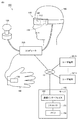
図2を参照して、本開示に係る技術思想を実現する装置構成について説明する。図2は、仮想空間に提示される画像に対してコメントを付加するための構成の概略を表わす図である。仮想空間は、HMD110によって提供される。HMD110は、周知の構成を有するサーバコンピュータ20に通信可能に接続されている。サーバコンピュータ20は、一つ以上のユーザ端末201A,201B,201N(総称するときは、ユーザ端末201という。)と通信可能に接続されている。ユーザ端末201は、プロセッサ211と、モニタ212とを含む。ユーザ端末201は、ある局面で、例えば、周知の構成を有するコンピュータ、タブレット端末、スマートフォンその他の情報通信端末である。別の局面で、ユーザ端末201は、HMD110と同様に、当該ユーザのコンピュータと当該コンピュータに接続されたHMDによって実現されてもよい。   With reference to FIG. 2, an apparatus configuration that realizes the technical idea according to the present disclosure will be described. FIG. 2 is a diagram showing an outline of a configuration for adding a comment to an image presented in the virtual space. The virtual space is provided by the HMD 110. The HMD 110 is communicably connected to a server computer 20 having a known configuration. The server computer 20 is communicably connected to one or more user terminals 201A, 201B, 201N (referred to collectively as user terminals 201). The user terminal 201 includes a processor 211 and a monitor 212. In one aspect, the user terminal 201 is, for example, a computer, a tablet terminal, a smartphone, or other information communication terminal having a known configuration. In another aspect, similarly to the HMD 110, the user terminal 201 may be realized by the user's computer and an HMD connected to the computer.

HMD110は、サーバコンピュータ20から送られた映像信号に基づいて映像をモニタ112に表示する。ユーザがコントローラを操作すると、HMD110は、その操作を表わす情報をサーバコンピュータ20に送信する。サーバコンピュータ20は、その情報に基づいてHMD110に提示されている画像に含まれるオブジェクトを移動する等の処理を実行し、処理後の画像を表示するための映像信号をHMD110およびログインしているユーザ端末201A,201B,201Nに表示する。なお、HMD110に送信される映像信号の形式と、ユーザ端末201A,201B,201Nに送信される映像信号の形式は同一でも異なってもよい。HMD110に送信される映像信号は、没入感を維持しつつ仮想空間で使用されるための三次元のデータである。他方、ユーザ端末201A、201B,201Cに送信される映像信号は、没入感が求められない場合には、二次元で画像を表示するためのデータであってもよい。   The HMD 110 displays a video on the monitor 112 based on the video signal sent from the server computer 20. When the user operates the controller, the HMD 110 transmits information representing the operation to the server computer 20. The server computer 20 executes processing such as moving an object included in the image presented on the HMD 110 based on the information, and the HMD 110 and a logged-in user for displaying a video signal for displaying the processed image Displayed on the terminals 201A, 201B, and 201N. The format of the video signal transmitted to the HMD 110 and the format of the video signal transmitted to the user terminals 201A, 201B, 201N may be the same or different. The video signal transmitted to the HMD 110 is three-dimensional data for use in a virtual space while maintaining an immersive feeling. On the other hand, the video signals transmitted to the user terminals 201A, 201B, and 201C may be data for displaying an image in two dimensions when an immersive feeling is not required.

ユーザ端末201A,201B,201Nの各ユーザは、HMD110のユーザが見ている画像と同じ画像を視認できる。このとき、各ユーザは、タッチパネル、マウス、音声入力装置その他の入力デバイスを用いて、その画像に対するコメントを入力できる。入力されたコメントは、サーバコンピュータ20に送られる。サーバコンピュータ20は、そのコメントがHMD110に提示される画像を妨げないように、例えば、視界領域の端に重ねて表示する。あるいは、サーバコンピュータ20は、そのコメントを透明色で表示する。HMD110を装着したユーザは、仮想空間に提示される画像を確認しながら、そのコメントを視認できる。   Each user of the user terminals 201A, 201B, and 201N can visually recognize the same image as the image that the user of the HMD 110 is viewing. At this time, each user can input a comment on the image using a touch panel, a mouse, a voice input device, or other input devices. The input comment is sent to the server computer 20. For example, the server computer 20 displays the comment so as not to interfere with the image presented on the HMD 110 so as to overlap the edge of the viewing area. Alternatively, the server computer 20 displays the comment in a transparent color. The user wearing the HMD 110 can visually recognize the comment while confirming the image presented in the virtual space.

[HMDシステムの構成]
図3を参照して、HMD(Head Mounted Device)システム100の構成について説明する。図3は、ある実施の形態に従うHMDシステム100の構成の概略を表す図である。ある局面において、HMDシステム100は、家庭用のシステムとしてあるいは業務用のシステムとして提供される。なお、本実施の形態において、HMDとは、モニタを備える所謂ヘッドマウントディスプレイと、スマートホンその他のモニタを有する端末を装着可能なヘッドマウント機器のいずれをも含み得る。
[Configuration of HMD system]
The configuration of an HMD (Head Mounted Device) system 100 will be described with reference to FIG. FIG. 3 is a diagram representing a schematic configuration of HMD system 100 according to an embodiment. In one aspect, the HMD system 100 is provided as a home system or a business system. In the present embodiment, the HMD may include both a so-called head mounted display including a monitor and a head mounted device on which a terminal having a monitor such as a smartphone can be mounted.

HMDシステム100は、HMD110と、HMDセンサ120と、コントローラ160と、コンピュータ200とを備える。HMD110は、モニタ112と、注視センサ140とを含む。コントローラ160は、モーションセンサ130を含み得る。   The HMD system 100 includes an HMD 110, an HMD sensor 120, a controller 160, and a computer 200. The HMD 110 includes a monitor 112 and a gaze sensor 140. The controller 160 can include a motion sensor 130.

ある局面において、コンピュータ200は、インターネットその他のネットワーク19に接続可能であり、ネットワーク19に接続されているサーバ150その他のコンピュータと通信可能である。ユーザ端末201A・・・201Nが、ネットワーク19に接続されている。   In one aspect, the computer 200 can be connected to the Internet and other networks 19, and can communicate with the server 150 and other computers connected to the network 19. User terminals 201 </ b> A to 201 </ b> N are connected to the network 19.

別の局面において、HMDシステム100がHMDセンサ120を備える代わりに、HMD110がセンサ114を含んでもよい。   In another aspect, instead of the HMD system 100 including the HMD sensor 120, the HMD 110 may include the sensor 114.

サーバ150は、プロセッサ151と、メモリ152と、通信インターフェイス153とを含む。サーバ150は、周知の構成を有するコンピュータによって実現される。   The server 150 includes a processor 151, a memory 152, and a communication interface 153. The server 150 is realized by a computer having a known configuration.

HMD110は、ユーザの頭部に装着され、動作中に仮想空間をユーザに提供し得る。より具体的には、HMD110は、右目用の画像および左目用の画像をモニタ112にそれぞれ表示する。ユーザの各目がそれぞれの画像を視認すると、ユーザは、両目の視差に基づき当該画像を3次元の画像として認識し得る。   The HMD 110 may be worn on the user's head and provide a virtual space to the user during operation. More specifically, the HMD 110 displays a right-eye image and a left-eye image on the monitor 112, respectively. When each eye of the user visually recognizes each image, the user can recognize the image as a three-dimensional image based on the parallax of both eyes.

モニタ112は、例えば、非透過型の表示装置として実現される。ある局面において、モニタ112は、ユーザの両目の前方に位置するようにHMD110の本体に配置されている。したがって、ユーザは、モニタ112に表示される3次元画像を視認すると、仮想空間に没入することができる。ある実施の形態において、仮想空間は、例えば、背景、ユーザが操作可能なオブジェクト、ユーザが選択可能なメニューの画像を含む。ある実施の形態において、モニタ112は、所謂スマートフォンその他の情報表示端末が備える液晶モニタまたは有機EL(Electro Luminescence)モニタとして実現され得る。   The monitor 112 is realized as, for example, a non-transmissive display device. In one aspect, the monitor 112 is disposed on the main body of the HMD 110 so as to be positioned in front of both eyes of the user. Therefore, when the user visually recognizes the three-dimensional image displayed on the monitor 112, the user can be immersed in the virtual space. In one embodiment, the virtual space includes, for example, a background, an object that can be operated by the user, and an image of a menu that can be selected by the user. In an embodiment, the monitor 112 may be realized as a liquid crystal monitor or an organic EL (Electro Luminescence) monitor provided in a so-called smartphone or other information display terminal.

ある局面において、モニタ112は、右目用の画像を表示するためのサブモニタと、左目用の画像を表示するためのサブモニタとを含み得る。別の局面において、モニタ112は、右目用の画像と左目用の画像とを一体として表示する構成であってもよい。この場合、モニタ112は、高速シャッタを含む。高速シャッタは、画像がいずれか一方の目にのみ認識されるように、右目用の画像と左目用の画像とを交互に表示可能に作動する。   In one aspect, the monitor 112 may include a sub-monitor for displaying an image for the right eye and a sub-monitor for displaying an image for the left eye. In another aspect, the monitor 112 may be configured to display a right-eye image and a left-eye image together. In this case, the monitor 112 includes a high-speed shutter. The high-speed shutter operates so that an image for the right eye and an image for the left eye can be displayed alternately so that the image is recognized only by one of the eyes.

HMDセンサ120は、複数の光源(図示しない)を含む。各光源は例えば、赤外線を発するLED(Light Emitting Diode)により実現される。HMDセンサ120は、HMD110の動きを検出するためのポジショントラッキング機能を有する。HMDセンサ120は、この機能を用いて、現実空間内におけるHMD110の位置および傾きを検出する。   The HMD sensor 120 includes a plurality of light sources (not shown). Each light source is realized by, for example, an LED (Light Emitting Diode) that emits infrared rays. The HMD sensor 120 has a position tracking function for detecting the movement of the HMD 110. Using this function, the HMD sensor 120 detects the position and inclination of the HMD 110 in the real space.

なお、別の局面において、HMDセンサ120は、カメラにより実現されてもよい。この場合、HMDセンサ120は、カメラから出力されるHMD110の画像情報を用いて、画像解析処理を実行することにより、HMD110の位置および傾きを検出することができる。   In another aspect, HMD sensor 120 may be realized by a camera. In this case, the HMD sensor 120 can detect the position and inclination of the HMD 110 by executing image analysis processing using image information of the HMD 110 output from the camera.

別の局面において、HMD110は、位置検出器として、HMDセンサ120の代わりに、センサ114を備えてもよい。HMD110は、センサ114を用いて、HMD110自身の位置および傾きを検出し得る。例えば、センサ114が角速度センサ、地磁気センサ、加速度センサ、あるいはジャイロセンサ等である場合、HMD110は、HMDセンサ120の代わりに、これらの各センサのいずれかを用いて、自身の位置および傾きを検出し得る。一例として、センサ114が角速度センサである場合、角速度センサは、現実空間におけるHMD110の3軸周りの角速度を経時的に検出する。HMD110は、各角速度に基づいて、HMD110の3軸周りの角度の時間的変化を算出し、さらに、角度の時間的変化に基づいて、HMD110の傾きを算出する。また、HMD110は、透過型表示装置を備えていても良い。この場合、当該透過型表示装置は、その透過率を調整することにより、一時的に非透過型の表示装置として構成可能であってもよい。また、視野画像は仮想空間を構成する画像の一部に、現実空間を提示する構成を含んでいてもよい。例えば、HMD110に搭載されたカメラで撮影した画像を視野画像の一部に重畳して表示させてもよいし、当該透過型表示装置の一部の透過率を高く設定することにより、視野画像の一部から現実空間を視認可能にしてもよい。   In another aspect, the HMD 110 may include a sensor 114 instead of the HMD sensor 120 as a position detector. The HMD 110 can detect the position and inclination of the HMD 110 itself using the sensor 114. For example, when the sensor 114 is an angular velocity sensor, a geomagnetic sensor, an acceleration sensor, a gyro sensor, or the like, the HMD 110 detects its own position and inclination using any one of these sensors instead of the HMD sensor 120. Can do. As an example, when the sensor 114 is an angular velocity sensor, the angular velocity sensor detects angular velocities around the three axes of the HMD 110 in real space over time. The HMD 110 calculates a temporal change in the angle around the three axes of the HMD 110 based on each angular velocity, and further calculates an inclination of the HMD 110 based on the temporal change in the angle. The HMD 110 may include a transmissive display device. In this case, the transmissive display device may be temporarily configured as a non-transmissive display device by adjusting the transmittance. Further, the visual field image may include a configuration for presenting the real space in a part of the image configuring the virtual space. For example, an image captured by a camera mounted on the HMD 110 may be displayed so as to be superimposed on a part of the field-of-view image, or by setting the transmittance of a part of the transmissive display device to be high. Real space may be visible from a part.

注視センサ140は、ユーザ190の右目および左目の視線が向けられる方向(視線方向)を検出する。当該方向の検出は、例えば、公知のアイトラッキング機能によって実現される。注視センサ140は、当該アイトラッキング機能を有するセンサにより実現される。ある局面において、注視センサ140は、右目用のセンサおよび左目用のセンサを含むことが好ましい。注視センサ140は、例えば、ユーザ190の右目および左目に赤外光を照射するとともに、照射光に対する角膜および虹彩からの反射光を受けることにより各眼球の回転角を検出するセンサであってもよい。注視センサ140は、検出した各回転角に基づいて、ユーザ190の視線方向を検知することができる。   The gaze sensor 140 detects a direction (gaze direction) in which the gaze of the right eye and the left eye of the user 190 is directed. The detection of the direction is realized by, for example, a known eye tracking function. The gaze sensor 140 is realized by a sensor having the eye tracking function. In one aspect, the gaze sensor 140 preferably includes a right eye sensor and a left eye sensor. The gaze sensor 140 may be, for example, a sensor that irradiates the right eye and the left eye of the user 190 with infrared light and detects the rotation angle of each eyeball by receiving reflected light from the cornea and iris with respect to the irradiated light. . The gaze sensor 140 can detect the line-of-sight direction of the user 190 based on each detected rotation angle.

サーバ150は、コンピュータ200にプログラムを送信し得る。別の局面において、サーバ150は、他のユーザによって使用されるHMDに仮想現実を提供するための他のコンピュータ200と通信し得る。例えば、アミューズメント施設において、複数のユーザが参加型のゲームを行なう場合、各コンピュータ200は、各ユーザの動作に基づく信号を他のコンピュータ200と通信して、同じ仮想空間において複数のユーザが共通のゲームを楽しむことを可能にする。   Server 150 may send a program to computer 200. In another aspect, the server 150 may communicate with other computers 200 for providing virtual reality to HMDs used by other users. For example, when a plurality of users play a participatory game in an amusement facility, each computer 200 communicates a signal based on each user's operation with another computer 200, and a plurality of users are common in the same virtual space. Allows you to enjoy the game.

コントローラ160は、ユーザ190からコンピュータ200への命令の入力を受け付ける。ある局面において、コントローラ160は、ユーザ190によって把持可能に構成される。別の局面において、コントローラ160は、ユーザ190の身体あるいは衣類の一部に装着可能に構成される。別の局面において、コントローラ160は、コンピュータ200から送られる信号に基づいて、振動、音、光のうちの少なくともいずれかを出力するように構成されてもよい。別の局面において、コントローラ160は、仮想現実を提供する空間に配置されるオブジェクトの位置や動きを制御するためにユーザ190によって与えられる操作を受け付ける。   The controller 160 receives input of commands from the user 190 to the computer 200. In one aspect, the controller 160 is configured to be gripped by the user 190. In another aspect, the controller 160 is configured to be attachable to the body of the user 190 or a part of clothing. In another aspect, the controller 160 may be configured to output at least one of vibration, sound, and light based on a signal sent from the computer 200. In another aspect, the controller 160 accepts an operation given by the user 190 to control the position and movement of an object arranged in a space that provides virtual reality.

モーションセンサ130は、ある局面において、ユーザの手に取り付けられて、ユーザの手の動きを検出する。例えば、モーションセンサ130は、手の回転速度、回転数等を検出する。検出された信号は、コンピュータ200に送られる。モーションセンサ130は、例えば、手袋型のコントローラ160に設けられている。ある実施の形態において、現実空間における安全のため、コントローラ160は、手袋型のようにユーザ190の手に装着されることにより容易に飛んで行かないものに装着されるのが望ましい。別の局面において、ユーザ190に装着されないセンサがユーザ190の手の動きを検出してもよい。例えば、ユーザ190を撮影するカメラの信号が、ユーザ190の動作を表わす信号として、コンピュータ200に入力されてもよい。モーションセンサ130とコンピュータ200とは、有線により、または無線により互いに接続される。無線の場合、通信形態は特に限られず、例えば、Bluetooth(登録商標)その他の公知の通信手法が用いられる。   In one aspect, the motion sensor 130 is attached to the user's hand and detects the movement of the user's hand. For example, the motion sensor 130 detects the rotation speed, rotation speed, etc. of the hand. The detected signal is sent to the computer 200. The motion sensor 130 is provided in a glove-type controller 160, for example. In some embodiments, for safety in real space, it is desirable that the controller 160 be mounted on something that does not fly easily by being mounted on the hand of the user 190, such as a glove shape. In another aspect, a sensor that is not worn by the user 190 may detect the hand movement of the user 190. For example, a signal from a camera that captures the user 190 may be input to the computer 200 as a signal representing the operation of the user 190. The motion sensor 130 and the computer 200 are connected to each other by wire or wirelessly. In the case of wireless communication, the communication form is not particularly limited, and for example, Bluetooth (registered trademark) or other known communication methods are used.

[ハードウェア構成]
図4を参照して、本実施の形態に係るコンピュータ200について説明する。図4は、一局面に従うコンピュータ200のハードウェア構成の一例を表すブロック図である。コンピュータ200は、主たる構成要素として、プロセッサ10と、メモリ11と、ストレージ12と、入出力インターフェイス13と、通信インターフェイス14とを備える。各構成要素は、それぞれ、バス15に接続されている。
[Hardware configuration]
A computer 200 according to the present embodiment will be described with reference to FIG. FIG. 4 is a block diagram illustrating an example of a hardware configuration of computer 200 according to one aspect. The computer 200 includes a processor 10, a memory 11, a storage 12, an input / output interface 13, and a communication interface 14 as main components. Each component is connected to the bus 15.

プロセッサ10は、コンピュータ200に与えられる信号に基づいて、あるいは、予め定められた条件が成立したことに基づいて、メモリ11またはストレージ12に格納されているプログラムに含まれる一連の命令を実行する。ある局面において、プロセッサ10は、CPU(Central Processing Unit)、MPU(Micro Processor Unit)、FPGA(Field-Programmable Gate Array)その他のデバイスとして実現される。   The processor 10 executes a series of instructions included in the program stored in the memory 11 or the storage 12 based on a signal given to the computer 200 or based on the establishment of a predetermined condition. In one aspect, the processor 10 is realized as a CPU (Central Processing Unit), an MPU (Micro Processor Unit), an FPGA (Field-Programmable Gate Array), or other device.

メモリ11は、プログラムおよびデータを一時的に保存する。プログラムは、例えば、ストレージ12からロードされる。データは、コンピュータ200に入力されたデータと、プロセッサ10によって生成されたデータとを含む。ある局面において、メモリ11は、RAM(Random Access Memory)その他の揮発メモリとして実現される。   The memory 11 temporarily stores programs and data. The program is loaded from the storage 12, for example. The data includes data input to the computer 200 and data generated by the processor 10. In one aspect, the memory 11 is realized as a RAM (Random Access Memory) or other volatile memory.

ストレージ12は、プログラムおよびデータを永続的に保持する。ストレージ12は、例えば、ROM(Read-Only Memory)、ハードディスク装置、フラッシュメモリ、その他の不揮発記憶装置として実現される。ストレージ12に格納されるプログラムは、HMDシステム100において仮想空間を提供するためのプログラム、シミュレーションプログラム、ゲームプログラム、ユーザ認証プログラム、他のコンピュータ200との通信を実現するためのプログラムを含む。ストレージ12に格納されるデータは、仮想空間を規定するためのデータおよびオブジェクト等を含む。   The storage 12 holds programs and data permanently. The storage 12 is realized as, for example, a ROM (Read-Only Memory), a hard disk device, a flash memory, and other nonvolatile storage devices. The programs stored in the storage 12 include a program for providing a virtual space in the HMD system 100, a simulation program, a game program, a user authentication program, and a program for realizing communication with another computer 200. The data stored in the storage 12 includes data and objects for defining the virtual space.

なお、別の局面において、ストレージ12は、メモリカードのように着脱可能な記憶装置として実現されてもよい。さらに別の局面において、コンピュータ200に内蔵されたストレージ12の代わりに、外部の記憶装置に保存されているプログラムおよびデータを使用する構成が使用されてもよい。このような構成によれば、例えば、アミューズメント施設のように複数のHMDシステム100が使用される場面において、プログラムやデータの更新を一括して行なうことが可能になる。   In another aspect, the storage 12 may be realized as a removable storage device such as a memory card. In still another aspect, a configuration using a program and data stored in an external storage device may be used instead of the storage 12 built in the computer 200. According to such a configuration, for example, in a scene where a plurality of HMD systems 100 are used as in an amusement facility, it is possible to update programs and data collectively.

ある実施の形態において、入出力インターフェイス13は、HMD110、HMDセンサ120またはモーションセンサ130との間で信号を通信する。ある局面において、入出力インターフェイス13は、USB(Universal Serial Bus)インターフェイス、DVI(Digital Visual Interface)、HDMI(登録商標)(High-Definition Multimedia Interface)その他の端子を用いて実現される。なお、入出力インターフェイス13は上述のものに限られない。   In some embodiments, the input / output interface 13 communicates signals with the HMD 110, HMD sensor 120, or motion sensor 130. In one aspect, the input / output interface 13 is realized using a USB (Universal Serial Bus) interface, a DVI (Digital Visual Interface), an HDMI (registered trademark) (High-Definition Multimedia Interface), or other terminals. The input / output interface 13 is not limited to that described above.

ある実施の形態において、入出力インターフェイス13は、さらに、コントローラ160と通信し得る。例えば、入出力インターフェイス13は、モーションセンサ130から出力された信号の入力を受ける。別の局面において、入出力インターフェイス13は、プロセッサ10から出力された命令を、コントローラ160に送る。当該命令は、振動、音声出力、発光等をコントローラ160に指示する。コントローラ160は、当該命令を受信すると、その命令に応じて、振動、音声出力または発光のいずれかを実行する。   In certain embodiments, the input / output interface 13 may further communicate with the controller 160. For example, the input / output interface 13 receives a signal output from the motion sensor 130. In another aspect, the input / output interface 13 sends the instruction output from the processor 10 to the controller 160. The command instructs the controller 160 to vibrate, output sound, emit light, and the like. When the controller 160 receives the command, the controller 160 executes vibration, sound output, or light emission according to the command.

通信インターフェイス14は、ネットワーク19に接続されて、ネットワーク19に接続されている他のコンピュータ(例えば、サーバ150)と通信する。ある局面において、通信インターフェイス14は、例えば、LAN(Local Area Network)その他の有線通信インターフェイス、あるいは、WiFi(Wireless Fidelity)、Bluetooth(登録商標)、NFC(Near Field Communication)その他の無線通信インターフェイスとして実現される。なお、通信インターフェイス14は上述のものに限られない。   The communication interface 14 is connected to the network 19 and communicates with other computers (for example, the server 150) connected to the network 19. In one aspect, the communication interface 14 is realized as, for example, a local area network (LAN) or other wired communication interface, or a wireless communication interface such as WiFi (Wireless Fidelity), Bluetooth (registered trademark), NFC (Near Field Communication), or the like. Is done. The communication interface 14 is not limited to the above.

ある局面において、プロセッサ10は、ストレージ12にアクセスし、ストレージ12に格納されている1つ以上のプログラムをメモリ11にロードし、当該プログラムに含まれる一連の命令を実行する。当該1つ以上のプログラムは、コンピュータ200のオペレーティングシステム、仮想空間を提供するためのアプリケーションプログラム、コントローラ160を用いて仮想空間で実行可能なゲームソフトウェア等を含み得る。プロセッサ10は、入出力インターフェイス13を介して、仮想空間を提供するための信号をHMD110に送る。HMD110は、その信号に基づいてモニタ112に映像を表示する。   In one aspect, the processor 10 accesses the storage 12, loads one or more programs stored in the storage 12 into the memory 11, and executes a series of instructions included in the program. The one or more programs may include an operating system of the computer 200, an application program for providing a virtual space, game software that can be executed in the virtual space using the controller 160, and the like. The processor 10 sends a signal for providing a virtual space to the HMD 110 via the input / output interface 13. The HMD 110 displays an image on the monitor 112 based on the signal.

なお、図4に示される例では、コンピュータ200は、HMD110の外部に設けられる構成が示されているが、別の局面において、コンピュータ200は、HMD110に内蔵されてもよい。一例として、モニタ112を含む携帯型の情報通信端末(例えば、スマートフォン)がコンピュータ200として機能してもよい。   In the example illustrated in FIG. 4, the configuration in which the computer 200 is provided outside the HMD 110 is illustrated. However, in another aspect, the computer 200 may be incorporated in the HMD 110. As an example, a portable information communication terminal (for example, a smartphone) including the monitor 112 may function as the computer 200.

また、コンピュータ200は、複数のHMD110に共通して用いられる構成であってもよい。このような構成によれば、例えば、複数のユーザに同一の仮想空間を提供することもできるので、各ユーザは同一の仮想空間で他のユーザと同一のアプリケーションを楽しむことができる。   Further, the computer 200 may be configured to be used in common for a plurality of HMDs 110. According to such a configuration, for example, the same virtual space can be provided to a plurality of users, so that each user can enjoy the same application as other users in the same virtual space.

ある実施の形態において、HMDシステム100では、グローバル座標系が予め設定されている。グローバル座標系は、現実空間における鉛直方向、鉛直方向に直交する水平方向、ならびに、鉛直方向および水平方向の双方に直交する前後方向にそれぞれ平行な、3つの基準方向(軸)を有する。本実施の形態では、グローバル座標系は視点座標系の一つである。そこで、グローバル座標系における水平方向、鉛直方向(上下方向)、および前後方向は、それぞれ、x軸、y軸、z軸と規定される。より具体的には、グローバル座標系において、x軸は現実空間の水平方向に平行である。y軸は、現実空間の鉛直方向に平行である。z軸は現実空間の前後方向に平行である。   In an embodiment, in the HMD system 100, a global coordinate system is set in advance. The global coordinate system has three reference directions (axes) parallel to the vertical direction in the real space, the horizontal direction orthogonal to the vertical direction, and the front-rear direction orthogonal to both the vertical direction and the horizontal direction. In the present embodiment, the global coordinate system is one of the viewpoint coordinate systems. Therefore, the horizontal direction, the vertical direction (up-down direction), and the front-rear direction in the global coordinate system are defined as an x axis, a y axis, and a z axis, respectively. More specifically, in the global coordinate system, the x axis is parallel to the horizontal direction of the real space. The y axis is parallel to the vertical direction of the real space. The z axis is parallel to the front-rear direction of the real space.

ある局面において、HMDセンサ120は、赤外線センサを含む。赤外線センサが、HMD110の各光源から発せられた赤外線をそれぞれ検出すると、HMD110の存在を検出する。HMDセンサ120は、さらに、各点の値(グローバル座標系における各座標値)に基づいて、HMD110を装着したユーザ190の動きに応じた、現実空間内におけるHMD110の位置および傾きを検出する。より詳しくは、HMDセンサ120は、経時的に検出された各値を用いて、HMD110の位置および傾きの時間的変化を検出できる。   In one aspect, HMD sensor 120 includes an infrared sensor. When the infrared sensor detects the infrared rays emitted from each light source of the HMD 110, the presence of the HMD 110 is detected. The HMD sensor 120 further detects the position and inclination of the HMD 110 in the real space according to the movement of the user 190 wearing the HMD 110 based on the value of each point (each coordinate value in the global coordinate system). More specifically, the HMD sensor 120 can detect temporal changes in the position and inclination of the HMD 110 using each value detected over time.

グローバル座標系は現実空間の座標系と平行である。したがって、HMDセンサ120によって検出されたHMD110の各傾きは、グローバル座標系におけるHMD110の3軸周りの各傾きに相当する。HMDセンサ120は、グローバル座標系におけるHMD110の傾きに基づき、uvw視野座標系をHMD110に設定する。HMD110に設定されるuvw視野座標系は、HMD110を装着したユーザ190が仮想空間において物体を見る際の視点座標系に対応する。   The global coordinate system is parallel to the real space coordinate system. Therefore, each inclination of the HMD 110 detected by the HMD sensor 120 corresponds to each inclination around the three axes of the HMD 110 in the global coordinate system. The HMD sensor 120 sets the uvw visual field coordinate system to the HMD 110 based on the inclination of the HMD 110 in the global coordinate system. The uvw visual field coordinate system set in the HMD 110 corresponds to a viewpoint coordinate system when the user 190 wearing the HMD 110 views an object in the virtual space.

[uvw視野座標系]
図5を参照して、uvw視野座標系について説明する。図5は、ある実施の形態に従うHMD110に設定されるuvw視野座標系を概念的に表す図である。HMDセンサ120は、HMD110の起動時に、グローバル座標系におけるHMD110の位置および傾きを検出する。プロセッサ10は、検出された値に基づいて、uvw視野座標系をHMD110に設定する。
[Uvw visual field coordinate system]
The uvw visual field coordinate system will be described with reference to FIG. FIG. 5 is a diagram conceptually showing a uvw visual field coordinate system set in HMD 110 according to an embodiment. The HMD sensor 120 detects the position and inclination of the HMD 110 in the global coordinate system when the HMD 110 is activated. The processor 10 sets the uvw visual field coordinate system to the HMD 110 based on the detected value.

図5に示されるように、HMD110は、HMD110を装着したユーザの頭部を中心(原点)とした3次元のuvw視野座標系を設定する。より具体的には、HMD110は、グローバル座標系を規定する水平方向、鉛直方向、および前後方向(x軸、y軸、z軸)を、グローバル座標系内においてHMD110の各軸周りの傾きだけ各軸周りにそれぞれ傾けることによって新たに得られる3つの方向を、HMD110におけるuvw視野座標系のピッチ方向(u軸)、ヨー方向(v軸)、およびロール方向(w軸)として設定する。   As shown in FIG. 5, the HMD 110 sets a three-dimensional uvw visual field coordinate system with the head (origin) of the user wearing the HMD 110 as the center (origin). More specifically, the HMD 110 includes a horizontal direction, a vertical direction, and a front-rear direction (x-axis, y-axis, z-axis) that define the global coordinate system by an inclination around each axis of the HMD 110 in the global coordinate system. Three directions newly obtained by tilting around the axis are set as the pitch direction (u-axis), yaw direction (v-axis), and roll direction (w-axis) of the uvw visual field coordinate system in the HMD 110.

ある局面において、HMD110を装着したユーザ190が直立し、かつ、正面を視認している場合、プロセッサ10は、グローバル座標系に平行なuvw視野座標系をHMD110に設定する。この場合、グローバル座標系における水平方向(x軸)、鉛直方向(y軸)、および前後方向(z軸)は、HMD110におけるuvw視野座標系のピッチ方向(u軸)、ヨー方向(v軸)、およびロール方向(w軸)に一致する。   In a certain situation, when the user 190 wearing the HMD 110 stands upright and is viewing the front, the processor 10 sets the uvw visual field coordinate system parallel to the global coordinate system to the HMD 110. In this case, the horizontal direction (x-axis), vertical direction (y-axis), and front-back direction (z-axis) in the global coordinate system are the pitch direction (u-axis) and yaw direction (v-axis) of the uvw visual field coordinate system in the HMD 110. , And the roll direction (w axis).

uvw視野座標系がHMD110に設定された後、HMDセンサ120は、HMD110の動きに基づいて、設定されたuvw視野座標系におけるHMD110の傾き(傾きの変化量)を検出できる。この場合、HMDセンサ120は、HMD110の傾きとして、uvw視野座標系におけるHMD110のピッチ角(θu)、ヨー角(θv)、およびロール角(θw)をそれぞれ検出する。ピッチ角(θu)は、uvw視野座標系におけるピッチ方向周りのHMD110の傾き角度を表す。ヨー角(θv)は、uvw視野座標系におけるヨー方向周りのHMD110の傾き角度を表す。ロール角(θw)は、uvw視野座標系におけるロール方向周りのHMD110の傾き角度を表す。   After the uvw visual field coordinate system is set to the HMD 110, the HMD sensor 120 can detect the inclination (the amount of change in inclination) of the HMD 110 in the set uvw visual field coordinate system based on the movement of the HMD 110. In this case, the HMD sensor 120 detects the pitch angle (θu), yaw angle (θv), and roll angle (θw) of the HMD 110 in the uvw visual field coordinate system as the inclination of the HMD 110. The pitch angle (θu) represents the inclination angle of the HMD 110 around the pitch direction in the uvw visual field coordinate system. The yaw angle (θv) represents the inclination angle of the HMD 110 around the yaw direction in the uvw visual field coordinate system. The roll angle (θw) represents the inclination angle of the HMD 110 around the roll direction in the uvw visual field coordinate system.

HMDセンサ120は、検出されたHMD110の傾き角度に基づいて、HMD110が動いた後のHMD110におけるuvw視野座標系を、HMD110に設定する。HMD110と、HMD110のuvw視野座標系との関係は、HMD110の位置および傾きに関わらず、常に一定である。HMD110の位置および傾きが変わると、当該位置および傾きの変化に連動して、グローバル座標系におけるHMD110のuvw視野座標系の位置および傾きが変化する。   The HMD sensor 120 sets the uvw visual field coordinate system in the HMD 110 after the HMD 110 has moved to the HMD 110 based on the detected tilt angle of the HMD 110. The relationship between the HMD 110 and the uvw visual field coordinate system of the HMD 110 is always constant regardless of the position and inclination of the HMD 110. When the position and inclination of the HMD 110 change, the position and inclination of the uvw visual field coordinate system of the HMD 110 in the global coordinate system change in conjunction with the change of the position and inclination.

ある局面において、HMDセンサ120は、赤外線センサからの出力に基づいて取得される赤外線の光強度および複数の点間の相対的な位置関係(例えば、各点間の距離など)に基づいて、HMD110の現実空間内における位置を、HMDセンサ120に対する相対位置として特定してもよい。また、プロセッサ10は、特定された相対位置に基づいて、現実空間内(グローバル座標系)におけるHMD110のuvw視野座標系の原点を決定してもよい。   In one aspect, the HMD sensor 120 is based on the infrared light intensity acquired based on the output from the infrared sensor and the relative positional relationship between a plurality of points (for example, the distance between the points). The position in the real space may be specified as a relative position to the HMD sensor 120. Further, the processor 10 may determine the origin of the uvw visual field coordinate system of the HMD 110 in the real space (global coordinate system) based on the specified relative position.

[仮想空間]
図6を参照して、仮想空間についてさらに説明する。図6は、ある実施の形態に従う仮想空間2を表現する一態様を概念的に表す図である。仮想空間2は、中心21の360度方向の全体を覆う全天球状の構造を有する。図6では、説明を複雑にしないために、仮想空間2のうちの上半分の天球が例示されている。仮想空間2では各メッシュが規定される。各メッシュの位置は、仮想空間2に規定されるXYZ座標系における座標値として予め規定されている。コンピュータ200は、仮想空間2に展開可能なコンテンツ(静止画、動画等)を構成する各部分画像を、仮想空間2において対応する各メッシュにそれぞれ対応付けて、ユーザによって視認可能な仮想空間画像22が展開される仮想空間2をユーザに提供する。
[Virtual space]
The virtual space will be further described with reference to FIG. FIG. 6 is a diagram conceptually showing one aspect of expressing virtual space 2 according to an embodiment. The virtual space 2 has a spherical structure that covers the entire 360 ° direction of the center 21. In FIG. 6, the upper half of the celestial sphere in the virtual space 2 is illustrated for the sake of simplicity. In the virtual space 2, each mesh is defined. The position of each mesh is defined in advance as coordinate values in the XYZ coordinate system defined in the virtual space 2. The computer 200 associates each partial image constituting content (still image, moving image, etc.) that can be developed in the virtual space 2 with each corresponding mesh in the virtual space 2, and the virtual space image 22 that can be visually recognized by the user. Is provided to the user.

ある局面において、仮想空間2では、中心21を原点とするXYZ座標系が規定される。XYZ座標系は、例えば、グローバル座標系に平行である。XYZ座標系は視点座標系の一種であるため、XYZ座標系における水平方向、鉛直方向(上下方向)、および前後方向は、それぞれX軸、Y軸、Z軸として規定される。したがって、XYZ座標系のX軸(水平方向)がグローバル座標系のx軸と平行であり、XYZ座標系のY軸(鉛直方向)がグローバル座標系のy軸と平行であり、XYZ座標系のZ軸(前後方向)がグローバル座標系のz軸と平行である。   In one aspect, the virtual space 2 defines an XYZ coordinate system with the center 21 as the origin. The XYZ coordinate system is, for example, parallel to the global coordinate system. Since the XYZ coordinate system is a kind of viewpoint coordinate system, the horizontal direction, vertical direction (vertical direction), and front-rear direction in the XYZ coordinate system are defined as an X axis, a Y axis, and a Z axis, respectively. Therefore, the X axis (horizontal direction) of the XYZ coordinate system is parallel to the x axis of the global coordinate system, the Y axis (vertical direction) of the XYZ coordinate system is parallel to the y axis of the global coordinate system, and The Z axis (front-rear direction) is parallel to the z axis of the global coordinate system.

HMD110の起動時、すなわちHMD110の初期状態において、仮想カメラ1が、仮想空間2の中心21に配置される。仮想カメラ1は、現実空間におけるHMD110の動きに連動して、仮想空間2を同様に移動する。これにより、現実空間におけるHMD110の位置および向きの変化が、仮想空間2において同様に再現される。   When the HMD 110 is activated, that is, in the initial state of the HMD 110, the virtual camera 1 is disposed at the center 21 of the virtual space 2. The virtual camera 1 similarly moves in the virtual space 2 in conjunction with the movement of the HMD 110 in the real space. Thereby, changes in the position and orientation of the HMD 110 in the real space are similarly reproduced in the virtual space 2.

仮想カメラ1には、HMD110の場合と同様に、uvw視野座標系が規定される。仮想空間2における仮想カメラ1のuvw視野座標系は、現実空間(グローバル座標系)におけるHMD110のuvw視野座標系に連動するように規定されている。したがって、HMD110の傾きが変化すると、それに応じて、仮想カメラ1の傾きも変化する。また、仮想カメラ1は、HMD110を装着したユーザの現実空間における移動に連動して、仮想空間2において移動することもできる。   As with the HMD 110, the uvw visual field coordinate system is defined for the virtual camera 1. The uvw visual field coordinate system of the virtual camera 1 in the virtual space 2 is defined so as to be linked to the uvw visual field coordinate system of the HMD 110 in the real space (global coordinate system). Therefore, when the inclination of the HMD 110 changes, the inclination of the virtual camera 1 also changes accordingly. The virtual camera 1 can also move in the virtual space 2 in conjunction with the movement of the user wearing the HMD 110 in the real space.

仮想カメラ1の向きは、仮想カメラ1の位置および傾きに応じて決まるので、ユーザが仮想空間画像22を視認する際に基準となる視線(基準視線5)は、仮想カメラ1の向きに応じて決まる。コンピュータ200のプロセッサ10は、基準視線5に基づいて、仮想空間2における視界領域23を規定する。視界領域23は、仮想空間2のうち、HMD110を装着したユーザの視界に対応する。   Since the orientation of the virtual camera 1 is determined according to the position and inclination of the virtual camera 1, the reference line of sight (reference line of sight 5) when the user visually recognizes the virtual space image 22 depends on the orientation of the virtual camera 1. Determined. The processor 10 of the computer 200 defines the visual field region 23 in the virtual space 2 based on the reference line of sight 5. The visual field area 23 corresponds to the visual field of the user wearing the HMD 110 in the virtual space 2.

注視センサ140によって検出されるユーザ190の視線方向は、ユーザ190が物体を視認する際の視点座標系における方向である。HMD110のuvw視野座標系は、ユーザ190がモニタ112を視認する際の視点座標系に等しい。また、仮想カメラ1のuvw視野座標系は、HMD110のuvw視野座標系に連動している。したがって、ある局面に従うHMDシステム100は、注視センサ140によって検出されたユーザ190の視線方向を、仮想カメラ1のuvw視野座標系におけるユーザの視線方向とみなすことができる。   The gaze direction of the user 190 detected by the gaze sensor 140 is a direction in the viewpoint coordinate system when the user 190 visually recognizes the object. The uvw visual field coordinate system of the HMD 110 is equal to the viewpoint coordinate system when the user 190 visually recognizes the monitor 112. Further, the uvw visual field coordinate system of the virtual camera 1 is linked to the uvw visual field coordinate system of the HMD 110. Therefore, the HMD system 100 according to a certain aspect can regard the line-of-sight direction of the user 190 detected by the gaze sensor 140 as the line-of-sight direction of the user in the uvw visual field coordinate system of the virtual camera 1.

[ユーザの視線]
図7を参照して、ユーザの視線方向の決定について説明する。図7は、ある実施の形態に従うHMD110を装着するユーザ190の頭部を上から表した図である。
[User's line of sight]
With reference to FIG. 7, the determination of the user's line-of-sight direction will be described. FIG. 7 is a top view of the head of user 190 wearing HMD 110 according to an embodiment.

ある局面において、注視センサ140は、ユーザ190の右目および左目の各視線を検出する。ある局面において、ユーザ190が近くを見ている場合、注視センサ140は、視線R1およびL1を検出する。別の局面において、ユーザ190が遠くを見ている場合、注視センサ140は、視線R2およびL2を検出する。この場合、ロール方向wに対して視線R2およびL2がなす角度は、ロール方向wに対して視線R1およびL1がなす角度よりも小さい。注視センサ140は、検出結果をコンピュータ200に送信する。   In one aspect, gaze sensor 140 detects each line of sight of user 190's right eye and left eye. In a certain aspect, when the user 190 is looking near, the gaze sensor 140 detects the lines of sight R1 and L1. In another aspect, when the user 190 is looking far away, the gaze sensor 140 detects the lines of sight R2 and L2. In this case, the angle formed by the lines of sight R2 and L2 with respect to the roll direction w is smaller than the angle formed by the lines of sight R1 and L1 with respect to the roll direction w. The gaze sensor 140 transmits the detection result to the computer 200.

コンピュータ200が、視線の検出結果として、視線R1およびL1の検出値を注視センサ140から受信した場合には、その検出値に基づいて、視線R1およびL1の交点である注視点N1を特定する。一方、コンピュータ200は、視線R2およびL2の検出値を注視センサ140から受信した場合には、視線R2およびL2の交点を注視点N1として特定する。コンピュータ200は、特定した注視点N1の位置に基づき、ユーザ190の視線方向N0を特定する。コンピュータ200は、例えば、ユーザ190の右目Rと左目Lとを結ぶ直線の中点と、注視点N1とを通る直線の延びる方向を、視線方向N0として検出する。視線方向N0は、ユーザ190が両目により実際に視線を向けている方向である。また、視線方向N0は、視界領域23に対してユーザ190が実際に視線を向けている方向に相当する。   When the computer 200 receives the detection values of the lines of sight R1 and L1 from the gaze sensor 140 as the line-of-sight detection result, the computer 200 identifies the point of sight N1 that is the intersection of the lines of sight R1 and L1 based on the detection value. On the other hand, when the detected values of the lines of sight R2 and L2 are received from the gaze sensor 140, the computer 200 specifies the intersection of the lines of sight R2 and L2 as the point of sight N1. The computer 200 specifies the line-of-sight direction N0 of the user 190 based on the specified position of the gazing point N1. For example, the computer 200 detects the direction in which the straight line passing through the midpoint of the straight line connecting the right eye R and the left eye L of the user 190 and the gazing point N1 extends as the line-of-sight direction N0. The line-of-sight direction N0 is a direction in which the user 190 is actually pointing the line of sight with both eyes. The line-of-sight direction N0 corresponds to the direction in which the user 190 actually directs his / her line of sight with respect to the field-of-view area 23.

別の局面において、HMDシステム100は、HMDシステム100を構成するいずれかのパーツに、マイクおよびスピーカを備えてもよい。ユーザは、マイクに発話することにより、仮想空間2に対して、音声による指示を与えることができる。   In another aspect, the HMD system 100 may include a microphone and a speaker in any part constituting the HMD system 100. The user can give a voice instruction to the virtual space 2 by speaking to the microphone.

また、別の局面において、HMDシステム100は、テレビジョン放送受信チューナを備えてもよい。このような構成によれば、HMDシステム100は、仮想空間2においてテレビ番組を表示することができる。   In another aspect, HMD system 100 may include a television broadcast receiving tuner. According to such a configuration, the HMD system 100 can display a television program in the virtual space 2.

さらに別の局面において、HMDシステム100は、インターネットに接続するための通信回路、あるいは、電話回線に接続するための通話機能を備えていてもよい。   In still another aspect, the HMD system 100 may include a communication circuit for connecting to the Internet or a call function for connecting to a telephone line.

[視界領域]
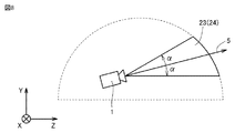
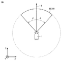
図8および図9を参照して、視界領域23について説明する。図8は、仮想空間2において視界領域23をX方向から見たYZ断面を表す図である。図9は、仮想空間2において視界領域23をY方向から見たXZ断面を表す図である。
[Visibility area]
The field-of-view area 23 will be described with reference to FIGS. FIG. 8 is a diagram illustrating a YZ cross section of the visual field region 23 viewed from the X direction in the virtual space 2. FIG. 9 is a diagram illustrating an XZ section of the visual field region 23 viewed from the Y direction in the virtual space 2.

図8に示されるように、YZ断面における視界領域23は、領域24を含む。領域24は、仮想カメラ1の基準視線5と仮想空間2のYZ断面とによって定義される。プロセッサ10は、仮想空間おける基準視線5を中心として極角αを含む範囲を、領域24として規定する。   As shown in FIG. 8, the visual field region 23 in the YZ cross section includes a region 24. The region 24 is defined by the reference line of sight 5 of the virtual camera 1 and the YZ cross section of the virtual space 2. The processor 10 defines a range including the polar angle α around the reference line of sight 5 in the virtual space as the region 24.

図9に示されるように、XZ断面における視界領域23は、領域25を含む。領域25は、基準視線5と仮想空間2のXZ断面とによって定義される。プロセッサ10は、仮想空間2における基準視線5を中心とした方位角βを含む範囲を、領域25として規定する。   As shown in FIG. 9, the visual field region 23 in the XZ cross section includes a region 25. The region 25 is defined by the reference line of sight 5 and the XZ cross section of the virtual space 2. The processor 10 defines a range including the azimuth angle β around the reference line of sight 5 in the virtual space 2 as a region 25.

ある局面において、HMDシステム100は、コンピュータ200からの信号に基づいて、視界画像26をモニタ112に表示させることにより、ユーザ190に仮想空間を提供する。視界画像26は、仮想空間画像22のうち視界領域23に重畳する部分に相当する。ユーザ190が、頭に装着したHMD110を動かすと、その動きに連動して仮想カメラ1も動く。その結果、仮想空間2における視界領域23の位置が変化する。これにより、モニタ112に表示される視界画像26は、仮想空間画像22のうち、仮想空間2においてユーザが向いた方向の視界領域23に重畳する画像に更新される。ユーザは、仮想空間2における所望の方向を視認することができる。   In one aspect, the HMD system 100 provides the virtual space to the user 190 by displaying the view image 26 on the monitor 112 based on a signal from the computer 200. The view image 26 corresponds to a portion of the virtual space image 22 that is superimposed on the view region 23. When the user 190 moves the HMD 110 worn on the head, the virtual camera 1 also moves in conjunction with the movement. As a result, the position of the visual field area 23 in the virtual space 2 changes. As a result, the view image 26 displayed on the monitor 112 is updated to an image that is superimposed on the view region 23 in the direction in which the user faces in the virtual space 2 in the virtual space image 22. The user can visually recognize a desired direction in the virtual space 2.

ユーザ190は、HMD110を装着している間、現実世界を視認することなく、仮想空間2に展開される仮想空間画像22のみを視認できる。そのため、HMDシステム100は、仮想空間2への高い没入感覚をユーザに与えることができる。   While wearing the HMD 110, the user 190 can visually recognize only the virtual space image 22 developed in the virtual space 2 without visually recognizing the real world. Therefore, the HMD system 100 can give the user a high sense of immersion in the virtual space 2.

ある局面において、プロセッサ10は、HMD110を装着したユーザ190の現実空間における移動に連動して、仮想空間2において仮想カメラ1を移動し得る。この場合、プロセッサ10は、仮想空間2における仮想カメラ1の位置および向きに基づいて、HMD110のモニタ112に投影される画像領域(すなわち、仮想空間2における視界領域23)を特定する。   In one aspect, the processor 10 can move the virtual camera 1 in the virtual space 2 in conjunction with the movement of the user 190 wearing the HMD 110 in the real space. In this case, the processor 10 specifies an image region (that is, a view field region 23 in the virtual space 2) projected on the monitor 112 of the HMD 110 based on the position and orientation of the virtual camera 1 in the virtual space 2.

ある実施の形態に従うと、仮想カメラ1は、二つの仮想カメラ、すなわち、右目用の画像を提供するための仮想カメラと、左目用の画像を提供するための仮想カメラとを含むことが望ましい。また、ユーザ190が3次元の仮想空間2を認識できるように、適切な視差が、二つの仮想カメラに設定されていることが好ましい。本実施の形態においては、仮想カメラ1が二つの仮想カメラを含み、二つの仮想カメラのロール方向が合成されることによって生成されるロール方向(w)がHMD110のロール方向(w)に適合されるように構成されているものとして、本開示に係る技術思想を例示する。   According to an embodiment, the virtual camera 1 preferably includes two virtual cameras, that is, a virtual camera for providing an image for the right eye and a virtual camera for providing an image for the left eye. Moreover, it is preferable that appropriate parallax is set in the two virtual cameras so that the user 190 can recognize the three-dimensional virtual space 2. In the present embodiment, the virtual camera 1 includes two virtual cameras, and the roll direction (w) generated by combining the roll directions of the two virtual cameras is adapted to the roll direction (w) of the HMD 110. The technical idea concerning this indication is illustrated as what is constituted.

[コントローラ]
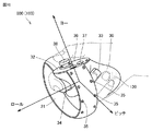
図10を参照して、コントローラ160の一例について説明する。図10は、ある実施の形態に従うコントローラ160の概略構成を表す図である。ある局面において、コントローラ160は、右コントローラ800と左コントローラとを含み得る。右コントローラ800は、ユーザ190の右手で操作される。左コントローラは、ユーザ190の左手で操作される。ある局面において、右コントローラ800と左コントローラとは、別個の装置として対称に構成される。したがって、ユーザ190は、右コントローラ800を把持した右手と、左コントローラを把持した左手とをそれぞれ自由に動かすことができる。別の局面において、コントローラ160は両手の操作を受け付ける一体型のコントローラであってもよい。以下、右コントローラ800について説明する。
[controller]
An example of the controller 160 will be described with reference to FIG. FIG. 10 is a diagram showing a schematic configuration of controller 160 according to an embodiment. In certain aspects, the controller 160 may include a right controller 800 and a left controller. The right controller 800 is operated with the right hand of the user 190. The left controller is operated with the left hand of the user 190. In one aspect, the right controller 800 and the left controller are configured symmetrically as separate devices. Therefore, the user 190 can freely move the right hand holding the right controller 800 and the left hand holding the left controller. In another aspect, the controller 160 may be an integrated controller that receives operations of both hands. Hereinafter, the right controller 800 will be described.

右コントローラ800は、グリップ30と、フレーム31と、天面32とを備える。グリップ30は、ユーザ190の右手によって把持されるように構成されている。例えば、グリップ30は、ユーザ190の右手の掌と3本の指(中指、薬指、小指)とによって保持され得る。   The right controller 800 includes a grip 30, a frame 31, and a top surface 32. The grip 30 is configured to be held by the right hand of the user 190. For example, the grip 30 can be held by the palm of the right hand of the user 190 and three fingers (middle finger, ring finger, little finger).

グリップ30は、ボタン33,34と、モーションセンサ130とを含む。ボタン33は、グリップ30の側面に配置され、右手の中指による操作を受け付ける。ボタン34は、グリップ30の前面に配置され、右手の人差し指による操作を受け付ける。ある局面において、ボタン33,34は、トリガー式のボタンとして構成される。モーションセンサ130は、グリップ30の筐体に内蔵されている。なお、ユーザ190の動作がカメラその他の装置によってユーザ190の周りから検出可能である場合には、グリップ30は、モーションセンサ130を備えなくてもよい。   The grip 30 includes buttons 33 and 34 and a motion sensor 130. The button 33 is disposed on the side surface of the grip 30 and receives an operation with the middle finger of the right hand. The button 34 is disposed in front of the grip 30 and accepts an operation with the index finger of the right hand. In one aspect, the buttons 33 and 34 are configured as trigger buttons. The motion sensor 130 is built in the housing of the grip 30. Note that when the operation of the user 190 can be detected from around the user 190 by a camera or other device, the grip 30 may not include the motion sensor 130.

フレーム31は、その円周方向に沿って配置された複数の赤外線LED35を含む。赤外線LED35は、コントローラ160を使用するプログラムの実行中に、当該プログラムの進行に合わせて赤外線を発光する。赤外線LED35から発せられた赤外線は、右コントローラ800と左コントローラ(図示しない)との各位置や姿勢(傾き、向き)を検出するために使用され得る。図8に示される例では、二列に配置された赤外線LED35が示されているが、配列の数は図8に示されるものに限られない。一列あるいは3列以上の配列が使用されてもよい。   The frame 31 includes a plurality of infrared LEDs 35 arranged along the circumferential direction. The infrared LED 35 emits infrared light in accordance with the progress of the program during the execution of the program using the controller 160. The infrared rays emitted from the infrared LED 35 can be used to detect the positions and postures (tilt and orientation) of the right controller 800 and the left controller (not shown). In the example shown in FIG. 8, infrared LEDs 35 arranged in two rows are shown, but the number of arrays is not limited to that shown in FIG. An array of one or more columns may be used.

天面32は、ボタン36,37と、アナログスティック38とを備える。ボタン36,37は、プッシュ式ボタンとして構成される。ボタン36,37は、ユーザ190の右手の親指による操作を受け付ける。アナログスティック38は、ある局面において、初期位置(ニュートラルの位置)から360度任意の方向への操作を受け付ける。当該操作は、例えば、仮想空間2に配置されるオブジェクトを移動するための操作を含む。   The top surface 32 includes buttons 36 and 37 and an analog stick 38. The buttons 36 and 37 are configured as push buttons. The buttons 36 and 37 receive an operation with the thumb of the right hand of the user 190. In one aspect, the analog stick 38 accepts an operation in an arbitrary direction of 360 degrees from the initial position (neutral position). The operation includes, for example, an operation for moving an object arranged in the virtual space 2.

ある局面において、右コントローラ800および左コントローラは、赤外線LED35その他の部材を駆動するための電池を含む。電池は、充電式、ボタン型、乾電池型等を含むが、これらに限定されない。別の局面において、右コントローラ800と左コントローラは、例えば、コンピュータ200のUSBインターフェイスに接続され得る。この場合、右コントローラ800および左コントローラは、電池を必要としない。   In one aspect, the right controller 800 and the left controller include a battery for driving the infrared LED 35 and other members. The battery includes, but is not limited to, a rechargeable type, a button type, a dry battery type, and the like. In another aspect, the right controller 800 and the left controller may be connected to a USB interface of the computer 200, for example. In this case, the right controller 800 and the left controller do not require batteries.

図11は、右コントローラ800を把持するユーザ190の右手に対応して仮想空間に配置されるハンドオブジェクト810の一例を示す。例えば、ユーザ190の右手に対応するハンドオブジェクト810に対して、ヨー、ロール、ピッチの各方向が規定される。例えば、入力操作が、右コントローラ800のボタン34に対して行なわれると、ハンドオブジェクト810の人差し指を握りこんだ状態とし、入力操作がボタン34に対して行なわれていない場合には、ハンドオブジェクト810の人差し指を伸ばした状態とすることもできる。例えば、ハンドオブジェクト810において親指と人差し指とが伸びている場合に、親指の伸びる方向がヨー方向、人差し指の伸びる方向がロール方向、ヨー方向の軸およびロール方向の軸によって規定される平面に垂直な方向がピッチ方向としてハンドオブジェクト810に規定される。   FIG. 11 shows an example of a hand object 810 arranged in the virtual space corresponding to the right hand of the user 190 holding the right controller 800. For example, the yaw, roll, and pitch directions are defined for the hand object 810 corresponding to the right hand of the user 190. For example, when the input operation is performed on the button 34 of the right controller 800, the hand object 810 is held in the index finger, and when the input operation is not performed on the button 34, the hand object 810 is performed. The index finger can be extended. For example, when the thumb and index finger are extended in the hand object 810, the direction in which the thumb extends is the yaw direction, and the direction in which the index finger extends is perpendicular to the plane defined by the roll direction, the yaw direction axis, and the roll direction axis. The direction is defined in the hand object 810 as a pitch direction.

[HMD110の制御装置]
図12を参照して、HMD110の制御装置について説明する。ある実施の形態において、制御装置は周知の構成を有するコンピュータ200によって実現される。図12は、ある実施の形態に従うコンピュータ200をモジュール構成として表わすブロック図である。以下では、サーバコンピュータ20によるコメントの付加機能がコンピュータ200によって実現される場合を説明する。別の局面において、この付加機能は、サーバ150によって実現されてもよい。
[Control device of HMD110]
With reference to FIG. 12, the control apparatus of HMD110 is demonstrated. In one embodiment, the control device is realized by a computer 200 having a known configuration. FIG. 12 is a block diagram showing a computer 200 according to an embodiment as a module configuration. In the following, a case where the comment adding function by the server computer 20 is realized by the computer 200 will be described. In another aspect, this additional function may be realized by the server 150.

図12に示されるように、コンピュータ200は、表示制御モジュール220と、仮想空間制御モジュール230と、メモリモジュール240と、通信制御モジュール250とを備える。表示制御モジュール220は、サブモジュールとして、仮想カメラ制御モジュール221と、視界領域決定モジュール222と、視界画像生成モジュール223と、基準視線特定モジュール224と、コメント付加モジュール225とを含む。仮想空間制御モジュール230は、サブモジュールとして、仮想空間定義モジュール231と、仮想オブジェクト生成モジュール232と、コントローラ管理モジュール233とを含む。   As shown in FIG. 12, the computer 200 includes a display control module 220, a virtual space control module 230, a memory module 240, and a communication control module 250. The display control module 220 includes a virtual camera control module 221, a visual field region determination module 222, a visual field image generation module 223, a reference visual line identification module 224, and a comment addition module 225 as submodules. The virtual space control module 230 includes a virtual space definition module 231, a virtual object generation module 232, and a controller management module 233 as submodules.

ある実施の形態において、表示制御モジュール220と仮想空間制御モジュール230とは、プロセッサ10によって実現される。別の実施の形態において、複数のプロセッサ10が表示制御モジュール220と仮想空間制御モジュール230として作動してもよい。メモリモジュール240は、メモリ11またはストレージ12によって実現される。通信制御モジュール250は、通信インターフェイス14によって実現される。   In an embodiment, the display control module 220 and the virtual space control module 230 are realized by the processor 10. In another embodiment, multiple processors 10 may operate as the display control module 220 and the virtual space control module 230. The memory module 240 is realized by the memory 11 or the storage 12. The communication control module 250 is realized by the communication interface 14.

ある局面において、表示制御モジュール220は、HMD110のモニタ112における画像表示を制御する。仮想カメラ制御モジュール221は、仮想空間2に仮想カメラ1を配置し、仮想カメラ1の挙動、向き等を制御する。視界領域決定モジュール222は、HMD110を装着したユーザの頭の向きに応じて、視界領域23を規定する。視界画像生成モジュール223は、決定された視界領域23に基づいて、モニタ112に表示される視界画像26を生成する。   In one aspect, the display control module 220 controls image display on the monitor 112 of the HMD 110. The virtual camera control module 221 arranges the virtual camera 1 in the virtual space 2 and controls the behavior, orientation, and the like of the virtual camera 1. The view area determination module 222 defines the view area 23 according to the direction of the head of the user wearing the HMD 110. The view image generation module 223 generates a view image 26 to be displayed on the monitor 112 based on the determined view area 23.

基準視線特定モジュール224は、注視センサ140からの信号に基づいて、ユーザ190の視線を特定する。コメント付加モジュール225は、サーバ150を介して受信したコメントを、視界画像生成モジュール223によって生成された視界画像にオーバーラップさせる。   The reference line-of-sight identifying module 224 identifies the line of sight of the user 190 based on the signal from the gaze sensor 140. The comment adding module 225 overlaps the comment received via the server 150 with the view image generated by the view image generating module 223.

仮想空間制御モジュール230は、ユーザ190に提供される仮想空間2を制御する。仮想空間定義モジュール231は、仮想空間2を表わす仮想空間データを生成することにより、HMDシステム100における仮想空間2を規定する。仮想オブジェクト生成モジュール232は、仮想空間2に配置される対象物を生成する。対象物は、例えば、山、木その他の背景を構成するオブジェクト、コンピュータ200によって実現されるプログラムを構成するストーリーに従って提示される動物のオブジェクト(例えば、馬オブジェクト101)、動物のオブジェクトを捕まえるためのオブジェクト(例えば、ロープオブジェクト102)を含む。   The virtual space control module 230 controls the virtual space 2 provided to the user 190. The virtual space definition module 231 defines the virtual space 2 in the HMD system 100 by generating virtual space data representing the virtual space 2. The virtual object generation module 232 generates an object placed in the virtual space 2. The object is, for example, an object constituting a background such as a mountain, a tree, an animal object (for example, a horse object 101) presented according to a story constituting a program realized by the computer 200, or an object for capturing an animal object. Includes objects (eg, rope object 102).

コントローラ管理モジュール233は、仮想空間2においてユーザ190の動作を受け付けて、その動作に応じてコントローラオブジェクトを制御する。ある実施の形態に従うコントローラオブジェクトは、仮想空間2に配置される他のオブジェクトに対して命令を与えるコントローラとして機能する。ある局面において、コントローラ管理モジュール233は、仮想空間2において制御を受け付けるコントローラオブジェクトを仮想空間2に配置するためのデータを生成する。HMD110がこのデータを受信すると、モニタ112は、コントローラオブジェクトを表示し得る。   The controller management module 233 receives the operation of the user 190 in the virtual space 2 and controls the controller object according to the operation. A controller object according to an embodiment functions as a controller that gives instructions to other objects arranged in the virtual space 2. In one aspect, the controller management module 233 generates data for placing a controller object that receives control in the virtual space 2 in the virtual space 2. When the HMD 110 receives this data, the monitor 112 may display the controller object.

メモリモジュール240は、コンピュータ200が仮想空間2をユーザ190に提供するために使用されるデータを保持している。ある局面において、メモリモジュール240は、空間情報241と、ユーザ情報242と、コンテンツ243と、コメント244とを保持している。   The memory module 240 holds data used for the computer 200 to provide the virtual space 2 to the user 190. In one aspect, the memory module 240 holds space information 241, user information 242, content 243, and comments 244.

空間情報241は、仮想空間2を提供するために規定された1つ以上のテンプレートを保持している。ユーザ情報242は、HMD110のユーザ190の識別情報、ユーザ190に関連付けられている権限等を含む。当該権限は、例えば、アプリケーションを提供するウェブサイトにアクセスするためのアカウント情報(ユーザID、パスワード)等を含む。コンテンツ243は、例えば、HMD110によって提示されるコンテンツを含む。コメント244は、ユーザ端末201A・・・201Nのいずれかによって入力されたコメントである。   The space information 241 holds one or more templates defined for providing the virtual space 2. The user information 242 includes identification information of the user 190 of the HMD 110, authority associated with the user 190, and the like. The authority includes, for example, account information (user ID, password) for accessing a website that provides the application. The content 243 includes content presented by the HMD 110, for example. The comment 244 is a comment input by any of the user terminals 201A to 201N.

通信制御モジュール250は、ネットワーク19を介して、サーバ150その他の情報通信装置と通信し得る。通信制御モジュール250は、無線および有線のいずれであってもよい。   The communication control module 250 can communicate with the server 150 and other information communication devices via the network 19. The communication control module 250 may be either wireless or wired.

ある局面において、表示制御モジュール220および仮想空間制御モジュール230は、例えば、ユニティテクノロジーズ社によって提供されるUnity(登録商標)を用いて実現され得る。別の局面において、表示制御モジュール220および仮想空間制御モジュール230は、各処理を実現する回路素子の組み合わせとしても実現され得る。   In an aspect, the display control module 220 and the virtual space control module 230 may be realized using, for example, Unity (registered trademark) provided by Unity Technologies. In another aspect, the display control module 220 and the virtual space control module 230 can also be realized as a combination of circuit elements that realize each process.

コンピュータ200における処理は、ハードウェアと、プロセッサ10により実行されるソフトウェアとによって実現される。このようなソフトウェアは、ハードディスクその他のメモリモジュール240に予め格納されている場合がある。また、ソフトウェアは、CD−ROMその他のコンピュータ読み取り可能な不揮発性のデータ記録媒体に格納されて、プログラム製品として流通している場合もある。あるいは、当該ソフトウェアは、インターネットその他のネットワークに接続されている情報提供事業者によってダウンロード可能なプログラム製品として提供される場合もある。このようなソフトウェアは、光ディスク駆動装置その他のデータ読取装置によってデータ記録媒体から読み取られて、あるいは、通信制御モジュール250を介してサーバ150その他のコンピュータからダウンロードされた後、記憶モジュールに一旦格納される。そのソフトウェアは、プロセッサ10によって記憶モジュールから読み出され、実行可能なプログラムの形式でRAMに格納される。プロセッサ10は、そのプログラムを実行する。   Processing in the computer 200 is realized by hardware and software executed by the processor 10. Such software may be stored in advance in a memory module 240 such as a hard disk. The software may be stored in a CD-ROM or other non-volatile computer-readable data recording medium and distributed as a program product. Alternatively, the software may be provided as a program product that can be downloaded by an information provider connected to the Internet or other networks. Such software is read from a data recording medium by an optical disk drive or other data reader, or downloaded from the server 150 or other computer via the communication control module 250 and then temporarily stored in the storage module. . The software is read from the storage module by the processor 10 and stored in the RAM in the form of an executable program. The processor 10 executes the program.

コンピュータ200を構成するハードウェアは、一般的なものである。したがって、本実施の形態に係る最も本質的な部分は、コンピュータ200に格納されたプログラムであるともいえる。なお、コンピュータ200のハードウェアの動作は周知であるので、詳細な説明は繰り返さない。   The hardware that constitutes the computer 200 is general. Therefore, it can be said that the most essential part according to the present embodiment is a program stored in the computer 200. Since the hardware operation of computer 200 is well known, detailed description will not be repeated.

なお、データ記録媒体としては、CD−ROM、FD(Flexible Disk)、ハードディスクに限られず、磁気テープ、カセットテープ、光ディスク(MO(Magnetic Optical Disc)/MD(Mini Disc)/DVD(Digital Versatile Disc))、IC(Integrated Circuit)カード(メモリカードを含む)、光カード、マスクROM、EPROM(Electronically Programmable Read-Only Memory)、EEPROM(Electronically Erasable Programmable Read-Only Memory)、フラッシュROMなどの半導体メモリ等の固定的にプログラムを担持する不揮発性のデータ記録媒体でもよい。   The data recording medium is not limited to a CD-ROM, FD (Flexible Disk), and hard disk, but is a magnetic tape, cassette tape, optical disk (MO (Magnetic Optical Disc) / MD (Mini Disc) / DVD (Digital Versatile Disc)). ), IC (Integrated Circuit) card (including memory card), optical card, mask ROM, EPROM (Electronically Programmable Read-Only Memory), EEPROM (Electronically Erasable Programmable Read-Only Memory), flash ROM, etc. It may be a non-volatile data recording medium that carries a fixed program.

ここでいうプログラムとは、プロセッサ10により直接実行可能なプログラムだけでなく、ソースプログラム形式のプログラム、圧縮処理されたプログラム、暗号化されたプログラム等を含み得る。   The program here may include not only a program directly executable by the processor 10, but also a program in a source program format, a compressed program, an encrypted program, and the like.

[サーバコンピュータの構成]
図13を参照して、サーバコンピュータ20の構成についてさらに説明する。図13は、ある局面にしたがってサーバコンピュータ20により実現される機能の構成を表わすブロック図である。サーバコンピュータ20は、記憶部1310と、信号受信部1320と、映像信号加工部1330と、映像信号送信部1340と、コメント受信部1350と、画像生成部1360と、画像送信部1370とを備える。
[Configuration of server computer]
The configuration of the server computer 20 will be further described with reference to FIG. FIG. 13 is a block diagram showing a configuration of functions implemented by server computer 20 according to a certain aspect. The server computer 20 includes a storage unit 1310, a signal reception unit 1320, a video signal processing unit 1330, a video signal transmission unit 1340, a comment reception unit 1350, an image generation unit 1360, and an image transmission unit 1370.

記憶部1310は、サーバコンピュータ20に入力されるデータやプログラムを保持する。例えば、記憶部1310は、HMD110から送信されたデータ、ユーザ端末201A,201B,201Nのいずれかによって入力されたコメント、HMD110に表示されているコンテンツの配信先を保持する。記憶部1310は、メモリモジュール240として、例えば、フラッシュメモリ、ハードディスク装置その他の不揮発性メモリと、RAMのような揮発性メモリとによって実現され得る。   The storage unit 1310 holds data and programs input to the server computer 20. For example, the storage unit 1310 holds data transmitted from the HMD 110, comments input by any of the user terminals 201A, 201B, and 201N, and distribution destinations of content displayed on the HMD 110. The storage unit 1310 can be realized as the memory module 240 by, for example, a flash memory, a hard disk device or other nonvolatile memory, and a volatile memory such as a RAM.

信号受信部1320は、HMD110またはコンピュータ200から送信された映像信号を受信する。信号受信部1320は、通信制御モジュール250として実現される。   The signal receiving unit 1320 receives a video signal transmitted from the HMD 110 or the computer 200. The signal receiving unit 1320 is realized as the communication control module 250.

映像信号加工部1330は、信号受信部1320によって受信された映像信号の形式をユーザ端末201A,201B,201Nにおける表示に適合した形式の信号に変換する。例えば、HMD110において三次元画像を表示するための映像信号は、各ユーザ端末201において二次元画像を表示するための映像信号に変換される。映像信号加工部1330は、表示制御モジュール220によって実現される。   The video signal processing unit 1330 converts the format of the video signal received by the signal receiving unit 1320 into a signal in a format suitable for display on the user terminals 201A, 201B, and 201N. For example, a video signal for displaying a three-dimensional image on the HMD 110 is converted into a video signal for displaying a two-dimensional image on each user terminal 201. The video signal processing unit 1330 is realized by the display control module 220.

映像信号送信部1340は、配信先として記憶部1310に登録されているユーザ端末201に対して、映像信号加工部1330によって生成された映像信号を送信する。ユーザ端末201がその映像信号に基づく画像を表示すると、ユーザ端末201のユーザは、HMD110を装着したユーザ190が視認している画像を認識できる。ユーザ端末201のユーザが画像に対するコメントを入力して送信操作を行なうと、そのコメントはサーバコンピュータ20に送信される。このとき、コメントが表示される場所を指定する位置情報もサーバコンピュータ20に送信される。映像信号送信部1340は、通信制御モジュール250によって実現される。   The video signal transmission unit 1340 transmits the video signal generated by the video signal processing unit 1330 to the user terminal 201 registered in the storage unit 1310 as a distribution destination. When the user terminal 201 displays an image based on the video signal, the user of the user terminal 201 can recognize the image that the user 190 wearing the HMD 110 is viewing. When the user of the user terminal 201 inputs a comment for an image and performs a transmission operation, the comment is transmitted to the server computer 20. At this time, position information specifying a place where the comment is displayed is also transmitted to the server computer 20. The video signal transmission unit 1340 is realized by the communication control module 250.

コメント受信部1350は、ユーザ端末201から送信されたコメントと位置情報とを受信する。コメント受信部1350は、例えば、通信制御モジュール250によって実現される。受信されたコメントおよび位置情報は、記憶部1310に保存される。   The comment receiving unit 1350 receives the comment and position information transmitted from the user terminal 201. The comment receiving unit 1350 is realized by the communication control module 250, for example. The received comment and position information are stored in the storage unit 1310.

画像生成部1360は、記憶部1310に保存されているコメントおよび位置情報を用いて、HMD110に提示されるコメント画像を生成する。例えば、HMD110の向きや位置に関わらずコメントが視界画像の領域の同じ場所に表示されるように、画像生成部1360は、コメントの画像を生成する。画像生成部1360は、例えば、表示制御モジュール220によって、視界画像生成モジュール223およびコメント付加モジュール225として、実現され得る。   The image generation unit 1360 generates a comment image to be presented to the HMD 110 using the comments and position information stored in the storage unit 1310. For example, the image generation unit 1360 generates a comment image so that the comment is displayed at the same place in the field of view image regardless of the orientation and position of the HMD 110. The image generation unit 1360 can be realized as the view image generation module 223 and the comment addition module 225 by the display control module 220, for example.

画像送信部1370は、画像生成部1360によって生成されたコメント画像をHMD110に送信する。HMD110は、コンテンツの画像とコメント画像とがオーバーラップした画像を視認できる。このとき、コメント画像の位置は、HMD110の位置や向きに関わらず予め定めれた一定場所に定められている。   The image transmission unit 1370 transmits the comment image generated by the image generation unit 1360 to the HMD 110. The HMD 110 can visually recognize an image in which a content image and a comment image overlap. At this time, the position of the comment image is determined at a predetermined fixed position regardless of the position and orientation of the HMD 110.

図14を参照して、サーバコンピュータ20のデータ構造について説明する。図14は、記憶部1310におけるデータの格納の一態様を概念的に表す図である。記憶部1310は、テーブル1410,1420,1430を保持している。テーブル1410は、ユーザID1411と、ユーザ名1412と、パスワード1413と、最終ログイン日時1414とを含む。テーブル1420は、ユーザID1421とステータス1422とを含む。テーブル1430は、ユーザID1431と、コメント日時1432と、位置1433と、コメント1434と、フレーム番号1435とを含む。   The data structure of the server computer 20 will be described with reference to FIG. FIG. 14 is a diagram conceptually illustrating one mode of data storage in the storage unit 1310. The storage unit 1310 holds tables 1410, 1420, and 1430. The table 1410 includes a user ID 1411, a user name 1412, a password 1413, and a last login date 1414. The table 1420 includes a user ID 1421 and a status 1422. The table 1430 includes a user ID 1431, a comment date 1432, a position 1433, a comment 1434, and a frame number 1435.

テーブル1410は、あるコンテンツを共有しているユーザの情報を管理する。より具体的には、ユーザID1411は、配信サイトに登録されているユーザの識別データを表わす。ユーザ名1412は、当該ユーザの名前を表わす。パスワード1413は、ログインのために必要なパスワードを表わす。最終ログイン日時1414は、前回当該ユーザがログインしたに日時を表わす。   The table 1410 manages information on users who share certain contents. More specifically, the user ID 1411 represents user identification data registered in the distribution site. The user name 1412 represents the name of the user. A password 1413 represents a password necessary for login. The last login date 1414 represents the date and time when the user logged in last time.

テーブル1420は、当該コンテンツに対するユーザの状態を管理する。より具体的には、ユーザID1421は、現在ログインしているユーザの識別データを表わす。ステータス1422は、当該ユーザの現在の状態、例えば、コンテンツをプレイしているか否か、当該コンテンツを単に視聴しているか否かを表わす。   The table 1420 manages the user status for the content. More specifically, the user ID 1421 represents identification data of the currently logged-in user. The status 1422 represents the current state of the user, for example, whether the content is being played or whether the content is simply viewed.

テーブル1430は、各ユーザによって入力されたコメントを管理する。より具体的には、ユーザID1431は、コメントを書き込んだユーザを識別する。コメント日時1432は、当該コメントが書き込まれた日時を表わす。位置1433は、当該コメントが表示される位置を表わす。コメント1434は、コメントの内容を表わす。フレーム番号1435は、コンテンツを構成するフレームの番号である。フレーム番号1435は、コメントが書き込まれた、コンテンツにおける位置情報を表わす。別の局面において、フレーム番号1435の代わりに、コンテンツの再生位置を特定する時間情報が当該位置情報として保存されてもよい。当該コンテンツの再生が終了した後に、別の日時に、同じコンテンツの再生が指定された場合に、サーバコンピュータ20のプロセッサは、テーブル1430を参照することにより、そのコンテンツに対して書き込まれたコメントを読み出して、コンテンツと共にコメントを視聴者に提示できる。   The table 1430 manages comments input by each user. More specifically, the user ID 1431 identifies the user who wrote the comment. The comment date 1432 represents the date and time when the comment was written. A position 1433 represents a position where the comment is displayed. The comment 1434 represents the content of the comment. The frame number 1435 is a number of a frame constituting the content. Frame number 1435 represents position information in the content in which the comment is written. In another aspect, instead of the frame number 1435, time information for specifying the playback position of the content may be stored as the position information. When the reproduction of the same content is designated at another date and time after the reproduction of the content is finished, the processor of the server computer 20 refers to the table 1430 to change the comment written on the content. It can be read and comments can be presented to the viewer along with the content.

[制御構造]
図15を参照して、サーバコンピュータ20の制御構造について説明する。図15は、サーバコンピュータ20がコンピュータ200によって実現される場合に実行される処理の一部を表わすフローチャートである。
[Control structure]
A control structure of the server computer 20 will be described with reference to FIG. FIG. 15 is a flowchart showing a part of processing executed when server computer 20 is realized by computer 200.

ステップS1510にて、プロセッサ10は、通信制御モジュール250を介して、動画の配信サイトを提供するサーバ150にアクセスし、ログイン情報をサーバ150に送信する。   In step S <b> 1510, the processor 10 accesses the server 150 that provides a moving image distribution site via the communication control module 250, and transmits login information to the server 150.

ステップS1515にて、プロセッサ10は、通信制御モジュール250を介して、ユーザ190によって選択されたコンテンツ(例えば、360度動画、ゲームアプリケーション、チャットアプリケーション)の配信要求をサーバ150に送信する。サーバ150は、その要求に応答して、当該コンテンツを20に送信する。   In step S1515, the processor 10 transmits a distribution request for the content (for example, 360-degree moving image, game application, chat application) selected by the user 190 to the server 150 via the communication control module 250. The server 150 transmits the content to 20 in response to the request.

ステップS1520にて、プロセッサ10は、通信制御モジュール250を介して、動画を表示するための映像信号をサーバ150から受信する。   In step S1520, processor 10 receives a video signal for displaying a moving image from server 150 via communication control module 250.

ステップS1525にて、プロセッサ10は、視界画像生成モジュール223として、映像信号に基づく視界画像を仮想空間に提示するためのデータ(コンテンツ画像データ)を生成する。   In step S1525, the processor 10 generates data (content image data) for presenting a visual field image based on the video signal in the virtual space as the visual field image generation module 223.

ステップS1530にて、プロセッサ10は、コンテンツ画像データをHMD110に送信する。   In step S1530, processor 10 transmits the content image data to HMD 110.

ステップS1535にて、プロセッサ10は、コントローラ160からの信号に基づいて、ユーザ190の操作に応じた信号を受信したことを検知する。   In step S1535, the processor 10 detects that a signal corresponding to the operation of the user 190 has been received based on the signal from the controller 160.

ステップS1540にて、プロセッサ10は、視界画像生成モジュール223として、操作に応じたコンテンツ画像データを生成し、生成したコンテンツ画像データをサーバ150を介して他ユーザのユーザ端末(たとえば、ユーザ端末201A,201B・・・201N)等に送信する。   In step S1540, the processor 10 generates content image data corresponding to the operation as the view image generation module 223, and the generated content image data is transmitted to the other user's user terminal (for example, the user terminal 201A, 201B... 201N) or the like.

ステップS1545にて、プロセッサ10は、通信制御モジュール250を介して、他ユーザに入力されたコメントとコメントを表示する位置情報とをサーバ150から受信する。   In step S <b> 1545, the processor 10 receives, from the server 150, a comment input by another user and position information for displaying the comment via the communication control module 250.

ステップS1550にて、プロセッサ10は、コメントをHMD110に表示するためのデータ(コメント画像データ)を生成する。ある局面において、プロセッサ10は、HMD110に提示される仮想空間を表示するためのアプリケーションに基づく画像データとは別に、当該コメントをHMD110に表示するためのデータを生成する。   In step S1550, processor 10 generates data (comment image data) for displaying a comment on HMD 110. In one aspect, the processor 10 generates data for displaying the comment on the HMD 110 separately from the image data based on the application for displaying the virtual space presented on the HMD 110.

ステップS1555にて、プロセッサ10は、コメント付加モジュール225として、コンテンツ画像データとコメント画像データとを用いて、コンテンツとコメントとがオーバーラップされた視界画像データを生成する。   In step S1555, the processor 10 uses the content image data and the comment image data as the comment addition module 225 to generate view field image data in which the content and the comment are overlapped.

ステップS1560にて、プロセッサ10は、視界画像データをHMD110に出力する。ユーザ190は、モニタ112に表示されたコメントを認識し得る。   In step S1560, processor 10 outputs the view image data to HMD 110. The user 190 can recognize the comment displayed on the monitor 112.

図16を参照して、別の局面におけるサーバコンピュータ20の制御構造について説明する。図16は、サーバコンピュータ20がサーバ150によって実現される場合に実行される処理の一部を表わすフローチャートである。   With reference to FIG. 16, the control structure of server computer 20 in another aspect will be described. FIG. 16 is a flowchart showing a part of processing executed when server computer 20 is realized by server 150.

ステップS1610にて、サーバ150のプロセッサ151は、コンピュータ200から送られる信号に基づいて、HMD110を装着したユーザ190のログインを検知し、受信した信号に含まれるユーザIDおよびパスワードと、登録情報として予め保持しているユーザIDおよびパスワードとを用いて、認証処理を実行する。   In step S1610, the processor 151 of the server 150 detects the login of the user 190 wearing the HMD 110 based on the signal sent from the computer 200, and previously stores the user ID and password included in the received signal as registration information. The authentication process is executed using the held user ID and password.

ステップS1620にて、サーバ150のプロセッサ151は、ユーザ190に指定されたアプリケーションプログラムを記憶装置からRAMにロードする。プロセッサ151は、そのロードしたアプリケーションプログラムを実行し、その実行に基づく映像信号をコンピュータ200に送信する。HMD110は、その映像信号に基づき仮想空間2にコンテンツを表示する。ユーザ190は、そのコンテンツを見ながらコントローラ160を操作し得る。捜査情報は、コントローラ160からコンピュータ200に送られ、コンテンツの表示が変わる。   In step S1620, processor 151 of server 150 loads the application program designated by user 190 from the storage device to the RAM. The processor 151 executes the loaded application program and transmits a video signal based on the execution to the computer 200. The HMD 110 displays content in the virtual space 2 based on the video signal. The user 190 can operate the controller 160 while viewing the content. The investigation information is sent from the controller 160 to the computer 200, and the display of content changes.

ステップS1630にて、サーバ150のプロセッサ151は、当該ユーザの操作に基づき画像を表示するための映像信号をコンピュータ200から受信する。   In step S1630, processor 151 of server 150 receives a video signal for displaying an image from computer 200 based on the operation of the user.

ステップS1640にて、サーバ150のプロセッサ151は、ユーザ端末201A等から受信した信号に基づいて、他ユーザによるログインを検知し、ユーザIDおよびパスワードを用いて認証処理を実行する。予め登録されている正規のユーザによるログイン要求であることが確認されると、サーバ150は、当該ユーザ端末201A等によるアクセスを受け付ける。   In step S1640, processor 151 of server 150 detects login by another user based on a signal received from user terminal 201A or the like, and executes an authentication process using the user ID and password. When it is confirmed that the login request is issued by an authorized user registered in advance, the server 150 accepts access from the user terminal 201A or the like.

ステップS1650にて、サーバ150のプロセッサ151は、三次元画像として視認される画像を二次元表示用の画像に変換して、変換により生成された映像信号を他ユーザのユーザ端末201A等に送信する。ユーザ端末201Aは、そのモニタに、ユーザ190が視聴しているコンテンツと同じコンテンツを表示するので、当該他ユーザもそのコンテンツを楽しむことができる。他ユーザは、そのコンテンツを見ながら、ユーザ190に対するコメントを入力装置を用いて入力できる。入力されたコメントは、位置情報と共に、サーバ150に送信される。   In step S1650, processor 151 of server 150 converts an image viewed as a three-dimensional image into an image for two-dimensional display, and transmits the video signal generated by the conversion to user terminal 201A of another user or the like. . Since the user terminal 201A displays the same content as the content that the user 190 is viewing on the monitor, the other user can also enjoy the content. Other users can input comments for the user 190 using the input device while viewing the content. The input comment is transmitted to the server 150 together with the position information.

ステップS1660にて、サーバ150のプロセッサ151は、他ユーザのユーザ端末201A,201B・・・201Nのいずれかからのコメントを受信する。   In step S1660, processor 151 of server 150 receives a comment from any of user terminals 201A, 201B,.

ステップS1670にて、サーバ150のプロセッサ151は、コメントを視界画像として表示するための映像信号を生成し、生成した映像信号をHMD110を装着したユーザ190のコンピュータ200に送信する。HMD110のモニタ112は、コンテンツの画像にオーバーラップされたコメントを表示し得る。   In step S1670, processor 151 of server 150 generates a video signal for displaying the comment as a view field image, and transmits the generated video signal to computer 200 of user 190 wearing HMD 110. The monitor 112 of the HMD 110 may display a comment overlapped with the content image.

図17を参照して、他ユーザの端末の制御構造について説明する。図17は、他ユーザのユーザ端末201Aによって実行される処理の一部を表わすフローチャートである。   With reference to FIG. 17, the control structure of another user's terminal is demonstrated. FIG. 17 is a flowchart showing a part of the processing executed by user terminal 201A of another user.

ステップS1710にて、プロセッサ211は、他ユーザの操作に基づいて、モニタ212に表示されている配信サイトにログインする。ステップS1720にて、プロセッサ211は、他ユーザの操作に基づいて、配信を希望するコンテンツの選択を受け付ける。例えば、他ユーザは、ユーザ190が視聴しているコンテンツを選択し得る。ステップS1730にて、プロセッサ211は、コンテンツの配信要求をサーバ150に送信する。   In step S1710, processor 211 logs in to the distribution site displayed on monitor 212 based on the operation of another user. In step S1720, processor 211 accepts selection of content desired to be distributed based on the operation of another user. For example, the other user can select the content that the user 190 is viewing. In step S1730, processor 211 transmits a content distribution request to server 150.

ステップS1740にて、プロセッサ211は、サーバ150から映像信号を受信し、その信号に基づく映像をモニタ212に表示する。ステップS1750にて、プロセッサ211は、マウス、キーボード、タッチパネル等の入力インターフェイスを介して、映像に対するコメントの入力を受け付ける。   In step S1740, processor 211 receives a video signal from server 150 and displays video based on the signal on monitor 212. In step S1750, processor 211 accepts input of a comment on the video via an input interface such as a mouse, a keyboard, or a touch panel.

ステップS1760にて、プロセッサ211は、コメントをサーバ150に送信する。サーバ150が、このコメントをHMD110が接続されたコンピュータ200に送信すると、コメントは、モニタ112に表示される。   In step S1760, processor 211 transmits a comment to server 150. When the server 150 transmits this comment to the computer 200 to which the HMD 110 is connected, the comment is displayed on the monitor 112.

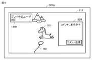
図18を参照して、ユーザ端末201Aにおける画面の表示態様について説明する。図18は、ユーザ端末201Aのモニタ212に表示される画面の一例を表わす図である。ある局面において、モニタ212は、ユーザ190が装着しているHMD110のモニタ112に表示されるコンテンツと同じコンテンツを表示する。さらに、モニタ212は、プレイ中のユーザがユーザ190(=ユーザ0001)であることを表わす画像1810と、コメントその送信を促す画像1820とを表示する。画像1810と画像1820とは、例えば、ポップアップ画像である。   With reference to FIG. 18, the display mode of the screen in user terminal 201A will be described. FIG. 18 is a diagram illustrating an example of a screen displayed on the monitor 212 of the user terminal 201A. In one aspect, the monitor 212 displays the same content as the content displayed on the monitor 112 of the HMD 110 worn by the user 190. Furthermore, the monitor 212 displays an image 1810 indicating that the user who is playing is the user 190 (= user 0001), and an image 1820 prompting the transmission of the comment. The image 1810 and the image 1820 are, for example, pop-up images.

例えば、ユーザ端末201Aが、モニタ112に表示されているコンテンツの表示を開始すると、モニタ212は、予め定められた時間、画像1810を表示する。別の局面において、ユーザ190がコントローラ160を操作すると、その操作に応答して、画像1810が表示される。この場合、ユーザ端末201Aを使用する他ユーザは、当該操作に応答してシーンが移り変わると、プレイ中のユーザを知ることができる。   For example, when the user terminal 201A starts displaying the content displayed on the monitor 112, the monitor 212 displays the image 1810 for a predetermined time. In another aspect, when the user 190 operates the controller 160, an image 1810 is displayed in response to the operation. In this case, another user using the user terminal 201A can know the user who is playing when the scene changes in response to the operation.

画像1820は、ある局面において、予め定められた時間ごとに表示される。別の局面において、画像1820は、画像1810と同様に、ユーザ190が何らかの操作を行なったタイミングに応答して表示される。この場合、他ユーザは、ユーザ190の操作に対するコメントの入力タイミングを逸しにくくなるので、例えば図1に示されるように、他ユーザのコメントも速やかにモニタ112に表示される。その結果、ユーザ190もタイムリーなコメントを視認しやすくなる。   The image 1820 is displayed every predetermined time in a certain situation. In another aspect, image 1820 is displayed in response to the timing when user 190 performs some operation, similar to image 1810. In this case, since it becomes difficult for other users to miss the comment input timing for the operation of the user 190, the comments of the other users are also quickly displayed on the monitor 112 as shown in FIG. As a result, the user 190 can easily view timely comments.

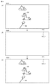
図19を参照して、モニタ112におけるコンテンツおよびコメントの表示について説明する。図19は、モニタ112に画像を表示するためのデータの生成の流れを概念的に表す図である。   The display of content and comments on the monitor 112 will be described with reference to FIG. FIG. 19 is a diagram conceptually showing a flow of generating data for displaying an image on the monitor 112.

状態Aに示されるように、ある局面において、メモリ11は、一部のワーク領域に、モニタ112にコンテンツを表示するための描画データ1910を保持している。コンテンツは、馬オブジェクト101およびロープオブジェクト102を含む。   As shown in state A, in one aspect, the memory 11 holds drawing data 1910 for displaying content on the monitor 112 in a part of the work area. The content includes a horse object 101 and a rope object 102.

状態Bに示されるように、メモリ11は、上記ワーク領域とは異なる別のワーク領域に、他ユーザによって入力されたコメント1921を表示するための描画データ1920を保持している。描画データ1920は、コメント1921がコンピュータ200において受信された後に生成される。なお、コメント1921が表示される場所は、HMD110の向きや姿勢に関わらず、モニタ112の一定の場所に維持される。したがって、例えば、馬オブジェクト101が仮想空間2において移動することにより、視線方向(仮想カメラ1の方向)が動いた場合であっても、コメント1921は、モニタ112の一定位置に表示されることになる。このような表示のための位置関係は、例えば、モニタ112の表示領域を絶対位置の座標値とし、コメント1921の表示場所を、当該絶対位置の座標値に関連付けて規定することで維持される。   As shown in state B, the memory 11 holds drawing data 1920 for displaying a comment 1921 input by another user in another work area different from the work area. The drawing data 1920 is generated after the comment 1921 is received by the computer 200. Note that the place where the comment 1921 is displayed is maintained at a certain place on the monitor 112 regardless of the orientation and orientation of the HMD 110. Therefore, for example, even when the line-of-sight direction (the direction of the virtual camera 1) moves due to the horse object 101 moving in the virtual space 2, the comment 1921 is displayed at a fixed position on the monitor 112. Become. Such a positional relationship for display is maintained, for example, by defining the display area of the monitor 112 as a coordinate value of the absolute position and defining the display location of the comment 1921 in association with the coordinate value of the absolute position.

状態Cに示されるように、メモリ11は、さらに別のワーク領域に、描画データ1930を保持する。描画データ1930は、描画データ1910と描画データ1920とを構成することにより生成される。プロセッサ10は、描画データ1930をHMD110に送信すると、モニタ112は、図1の状態Aに示されるような画像を表示する。その他の画像についても同様に、コメントが表示される(図1の状態B、状態C)。   As shown in the state C, the memory 11 holds the drawing data 1930 in yet another work area. The drawing data 1930 is generated by configuring drawing data 1910 and drawing data 1920. When the processor 10 transmits the drawing data 1930 to the HMD 110, the monitor 112 displays an image as shown in the state A of FIG. Similarly, comments are displayed for other images (state B and state C in FIG. 1).

図20を参照して、ユーザ端末201における画面の表示態様について説明する。図20は、ユーザ190によって入力されたコメントが他ユーザのユーザ端末201のモニタ212に表示される画面の一態様を表わす図である。モニタ212は、HMD110のモニタ112に表示されている仮想空間の画像に加えて、画像2010と、画像2020とを表示する。画像2010は、プレイしているユーザ190を表わす。画像2020は、ユーザ190によって入力されたコメントを表わす。例えば、ユーザ190がコンテンツを楽しんだ後に応答コメントを入力すると、当該応答コメントは、ユーザ190に対してコメントを送った他ユーザに送信される。このように、他ユーザとユーザ190との間でコメントが互いに送られることにより、ユーザ190と他ユーザとの対話が促進され得る。   With reference to FIG. 20, the display mode of the screen in the user terminal 201 is demonstrated. FIG. 20 is a diagram illustrating an aspect of a screen in which a comment input by user 190 is displayed on monitor 212 of user terminal 201 of another user. The monitor 212 displays an image 2010 and an image 2020 in addition to the virtual space image displayed on the monitor 112 of the HMD 110. The image 2010 represents the user 190 who is playing. An image 2020 represents a comment input by the user 190. For example, when the user 190 inputs a response comment after enjoying the content, the response comment is transmitted to the other user who sent the comment to the user 190. As described above, the comments between the other user and the user 190 are sent to each other, so that the interaction between the user 190 and the other user can be promoted.

以上より、本開示に係る技術的特徴は、以下のように要約され得る。
(第1構成) 仮想空間2を提供するHMD110における表示を制御するためにサーバコンピュータ20で実行される方法は、HMD110のユーザ190の操作に応じた映像を表示するための映像信号をHMD110に送信するステップと、サーバコンピュータ20と通信可能に接続されている一つ以上のユーザ端末201A,201B,201N等に映像信号を送信するステップと、映像信号に基づいて一つ以上のユーザ端末201A,201B,201N等に表示される映像に対して与えられる視聴者応答(例えば、コメント103,104,105,106等)を一つ以上のユーザ端末201A,201B,201N等から受信するステップと、HMD110のモニタ112に視聴者応答を提示させるステップとを含む。
As described above, the technical features according to the present disclosure can be summarized as follows.
(1st structure) The method performed in the server computer 20 in order to control the display in HMD110 which provides the virtual space 2 transmits the video signal for displaying the image | video according to operation of the user 190 of HMD110 to HMD110. A step of transmitting a video signal to one or more user terminals 201A, 201B, 201N and the like that are communicably connected to the server computer 20, and one or more user terminals 201A, 201B based on the video signal , 201N, etc., and receiving a viewer response (for example, comments 103, 104, 105, 106, etc.) from one or more user terminals 201A, 201B, 201N, etc. And causing the monitor 112 to present a viewer response.

(第2構成) 上記の構成に加えて、一つ以上のユーザ端末201A,201B,201N等に映像信号を送信するステップは、一つ以上のユーザ端末201A,201B,201N等に二次元の画像を表示するための信号を送信することを含む。   (2nd structure) In addition to said structure, the step which transmits a video signal to one or more user terminal 201A, 201B, 201N etc. is a two-dimensional image to one or more user terminal 201A, 201B, 201N etc. Transmitting a signal for displaying.

(第3構成) 上記の構成に加えて、視聴者応答を一つ以上のユーザ端末201A,201B,201N等から受信するステップは、仮想空間2において視聴者応答が提示される場所を指定する位置情報を受信するステップを含む。   (3rd structure) In addition to said structure, the step which receives a viewer response from one or more user terminal 201A, 201B, 201N etc. is a position which designates the place where a viewer response is shown in the virtual space 2. Receiving the information.

(第4構成) 上記の構成に加えて、視聴者応答を一つ以上のユーザ端末201A,201B,201N等から受信するステップは、複数のユーザ端末201A,201B,201N等の各々から視聴者応答を受信することを含む。位置情報を受信するステップは、各ユーザ端末201A,201B,201N等の位置情報をそれぞれ受信することを含む。モニタ112に視聴者応答を提示させるステップは、各位置情報が同じ位置を示している場合に各視聴者応答を互いにずらして提示させることを含む。   (Fourth Configuration) In addition to the above-described configuration, the step of receiving a viewer response from one or more user terminals 201A, 201B, 201N, etc. includes a viewer response from each of the plurality of user terminals 201A, 201B, 201N, etc. Receiving. The step of receiving position information includes receiving position information of each of the user terminals 201A, 201B, 201N, etc. The step of causing the monitor 112 to present the viewer response includes causing each viewer response to be presented in a shifted manner when the position information indicates the same position.

(第5構成) 上記のいずれかの構成に加えて、視聴者応答を一つ以上のユーザ端末201A,201B,201N等から受信するステップは、複数の視聴者応答を一つ以上のユーザ端末201A,201B,201N等から受信することを含む。視聴者応答を提示させるステップは、複数の視聴者応答のうちのいずれかの視聴者応答を他の視聴者応答にオーバーレイ表示することを含む。   (Fifth Configuration) In addition to any of the configurations described above, the step of receiving a viewer response from one or more user terminals 201A, 201B, 201N, etc. includes a plurality of viewer responses as one or more user terminals 201A. , 201B, 201N, etc. Presenting the viewer response includes overlaying any viewer response of the plurality of viewer responses on the other viewer responses.

(第6構成)上記方法は、上記のいずれかの構成に加えて、仮想空間2に提示された視聴者応答に対してユーザによって入力されるユーザ応答をサーバコンピュータ20から受信するステップと、ユーザ応答を表示するための信号を一つ以上のユーザ端末201A,201B,201N等に送信するステップとをさらに含む。   (Sixth Configuration) In addition to any of the above configurations, the method receives a user response input by the user from the server computer 20 in response to a viewer response presented in the virtual space 2, and the user And a step of transmitting a signal for displaying the response to one or more user terminals 201A, 201B, 201N, and the like.

(第7構成) 上記方法は、上記のいずれかの構成に加えて、仮想空間2に提示された視聴者応答を消去するステップをさらに含む。   (Seventh Configuration) In addition to any of the above configurations, the method further includes a step of deleting the viewer response presented in the virtual space 2.

(第8構成) 上記のいずれかの構成に加えて、視聴者応答を消去するステップは、仮想空間2に提示される画像の変化に応じてコメントを消去するステップを含む。   (8th structure) In addition to one of said structures, the step which erase | eliminates a viewer response includes the step which erase | eliminates a comment according to the change of the image shown in the virtual space 2. FIG.

(第9構成) 上記方法は、上記のいずれかの構成に加えて、映像信号と視聴者応答とを関連付けて記憶装置に保存するステップをさらに含む。   (Ninth Configuration) In addition to any of the above configurations, the method further includes a step of storing the video signal and the viewer response in a storage device in association with each other.

(第10構成) 上記方法は、上記の第9構成に加えて、映像信号に基づく映像を再生するステップと、映像の再生に応じて、当該映像信号に関連付けられた視聴者応答を仮想空間2に提示させるステップとをさらに含む。   (Tenth Configuration) In addition to the ninth configuration described above, the method includes a step of playing a video based on a video signal, and a viewer response associated with the video signal according to the playback of the video. Further presenting.

(第11構成) 上記方法は、上記のいずれかの構成に加えて、HMD110のユーザ190の動きを検出するステップと、動きに連動して、仮想空間2の視界画像をモニタ112に提示させるステップをさらに含む。視聴者応答を提示させるステップは、動きに連動することなく視聴者応答を提示させることを含む。   (Eleventh Configuration) In addition to any of the configurations described above, the method includes a step of detecting the movement of the user 190 of the HMD 110 and a step of causing the monitor 112 to present a visual field image of the virtual space 2 in conjunction with the movement. Further included. Presenting the viewer response includes presenting the viewer response without being linked to the movement.

以上のようにして、本開示に係る技術によれば、実況者であるユーザ190によって他のユーザ端末201に提供される映像に対して、ユーザ端末201のユーザ(視聴者)がコメントを入力すると、ユーザ190のHMD110が表示する映像内にそのコメントが表示される。例えば、表示領域の端部に、あるいは、仮想空間2に提示されるオブジェクトの向こう側に表示される。あるいは、コメントは、ポップアップ表示され得る。別の局面では、コメントは、ゲームその他のコンテンツの画面の上にオーバーレイ表示され得る。このようにコメントが表示されると、ユーザ190は、その没入感を阻害されることなく、コメントを確認できる。   As described above, according to the technology according to the present disclosure, when a user (viewer) of the user terminal 201 inputs a comment on the video provided to the other user terminal 201 by the user 190 who is a live commentator. The comment is displayed in the video displayed by the HMD 110 of the user 190. For example, it is displayed at the end of the display area or beyond the object presented in the virtual space 2. Alternatively, the comment can be popped up. In another aspect, the comment may be overlaid on a game or other content screen. When the comment is displayed in this way, the user 190 can confirm the comment without being disturbed by the immersive feeling.

今回開示された実施の形態はすべての点で例示であって制限的なものではないと考えられるべきである。本発明の範囲は上記した説明ではなくて特許請求の範囲によって示され、特許請求の範囲と均等の意味および範囲内でのすべての変更が含まれることが意図される。   The embodiment disclosed this time should be considered as illustrative in all points and not restrictive. The scope of the present invention is defined by the terms of the claims, rather than the description above, and is intended to include any modifications within the scope and meaning equivalent to the terms of the claims.

本開示に係る技術的特徴は、HMDを用いて仮想空間を提供する技術に適用可能である。   The technical features according to the present disclosure can be applied to a technology that provides a virtual space using an HMD.

1 仮想カメラ、2 仮想空間、5 基準視線、10,151,211 プロセッサ、11,152 メモリ、12 ストレージ、13 入出力インターフェイス、14,153 通信インターフェイス、15 バス、19 ネットワーク、20 サーバコンピュータ、21 中心、22 仮想空間画像、23 視界領域、24,25 領域、26 視界画像、30 グリップ、31 フレーム、32 天面、33,34,36,37 ボタン、38 アナログスティック、100 システム、101 馬オブジェクト、102 ロープオブジェクト、103,104,105,106,244,1434,1921 コメント、112,212 モニタ、114,120 センサ、130 モーションセンサ、140 注視センサ、150 サーバ、160 コントローラ、200 コンピュータ、201,201A,201B,201N ユーザ端末。   1 virtual camera, 2 virtual space, 5 reference line of sight, 10, 151, 211 processor, 11, 152 memory, 12 storage, 13 input / output interface, 14, 153 communication interface, 15 bus, 19 network, 20 server computer, 21 center , 22 virtual space image, 23 field of view, 24, 25 region, 26 field of view image, 30 grip, 31 frame, 32 top surface, 33, 34, 36, 37 buttons, 38 analog stick, 100 system, 101 horse object, 102 Rope object, 103, 104, 105, 106, 244, 1434, 1921 Comment, 112, 212 Monitor, 114, 120 Sensor, 130 Motion sensor, 140 Gaze sensor, 150 Server, 160 Controller, 200 computer, 201,201A, 201B, 201N user terminal.

Claims (13)

仮想空間を提供するヘッドマウントデバイスにおける表示を制御するためにコンピュータで実行される方法であって、
前記ヘッドマウントデバイスのユーザの操作に応じた映像を表示するための映像信号を前記ヘッドマウントデバイスに送信するステップと、
前記コンピュータと通信可能に接続されている一つ以上の表示端末に前記映像信号を送信するステップと、
前記映像信号に基づいて前記一つ以上の表示端末に表示される映像に対して与えられる視聴者応答を前記一つ以上の表示端末から受信するステップと、
前記ヘッドマウントデバイスに前記視聴者応答を提示させるステップとを含む、方法。
A computer-implemented method for controlling display in a head-mounted device that provides virtual space,
Transmitting a video signal for displaying a video according to an operation of a user of the head mounted device to the head mounted device;
Transmitting the video signal to one or more display terminals communicably connected to the computer;
Receiving, from the one or more display terminals, a viewer response given to the video displayed on the one or more display terminals based on the video signal;
Causing the head mounted device to present the viewer response.
前記一つ以上の表示端末に前記映像信号を送信するステップは、前記一つ以上の表示端末に二次元の画像を表示するための信号を送信することを含む、請求項1に記載の方法。   The method of claim 1, wherein transmitting the video signal to the one or more display terminals includes transmitting a signal for displaying a two-dimensional image to the one or more display terminals. 前記視聴者応答を前記一つ以上の表示端末から受信するステップは、前記仮想空間において前記視聴者応答が提示される場所を指定する位置情報を受信するステップを含む、請求項1または2に記載の方法。   The step of receiving the viewer response from the one or more display terminals includes receiving position information specifying a place where the viewer response is presented in the virtual space. the method of. 前記視聴者応答を前記一つ以上の表示端末から受信するステップは、複数の表示端末の各々から視聴者応答を受信することを含み、
前記位置情報を受信するステップは、各前記表示端末の位置情報をそれぞれ受信することを含み、
前記モニタに前記視聴者応答を提示させるステップは、各前記位置情報が同じ位置を示している場合に各前記視聴者応答を互いにずらして提示させることを含む、請求項3に記載の方法。
Receiving the viewer response from the one or more display terminals includes receiving a viewer response from each of a plurality of display terminals;
Receiving the position information includes receiving position information of each of the display terminals;
4. The method of claim 3, wherein causing the monitor to present the viewer response includes causing the viewer responses to be presented with a shift relative to each other when the location information indicates the same location.
前記視聴者応答を前記一つ以上の表示端末から受信するステップは、複数の前記視聴者応答を前記一つ以上の表示端末から受信することを含み、
前記視聴者応答を提示させるステップは、複数の前記視聴者応答のうちのいずれかの視聴者応答を他の視聴者応答にオーバーレイ表示することを含む、請求項1〜4のいずれかに記載の方法。
Receiving the viewer response from the one or more display terminals includes receiving a plurality of the viewer responses from the one or more display terminals;
5. The step of presenting the viewer response includes displaying the viewer response of any one of the plurality of viewer responses as an overlay on another viewer response. Method.
前記仮想空間に提示された視聴者応答に対して前記ユーザによって入力されるユーザ応答を前記コンピュータから受信するステップと、
前記ユーザ応答を表示するための信号を前記一つ以上の表示端末に送信するステップとをさらに含む、請求項1〜5のいずれかに記載の方法。
Receiving from the computer a user response input by the user in response to a viewer response presented in the virtual space;
The method according to claim 1, further comprising: transmitting a signal for displaying the user response to the one or more display terminals.
前記仮想空間に提示された視聴者応答を消去するステップをさらに含む、請求項1〜6のいずれかに記載の方法。   The method according to claim 1, further comprising the step of erasing a viewer response presented in the virtual space. 前記視聴者応答を消去するステップは、前記仮想空間に提示される画像の変化に応じてコメントを消去するステップを含む、請求項7に記載の方法。   The method of claim 7, wherein deleting the viewer response includes deleting a comment in response to a change in an image presented in the virtual space. 前記映像信号と前記視聴者応答とを関連付けて記憶装置に保存するステップをさらに含む、請求項1〜8のいずれかに記載の方法。   The method according to claim 1, further comprising the step of associating the video signal and the viewer response with a storage device. 前記映像信号に基づく映像を再生するステップと、
前記映像の再生に応じて、当該映像信号に関連付けられた視聴者応答を前記仮想空間に提示させるステップとをさらに含む、請求項9に記載の方法。
Playing a video based on the video signal;
10. The method of claim 9, further comprising: causing a viewer response associated with the video signal to be presented in the virtual space in response to playback of the video.
前記ヘッドマウントデバイスのユーザの動きを検出するステップと、
前記動きに連動して、前記仮想空間の視界画像を前記モニタに提示させるステップをさらに含み、
前記視聴者応答を提示させるステップは、前記動きに連動することなく前記視聴者応答を提示させることを含む、請求項1〜10のいずれかに記載の方法。
Detecting a movement of a user of the head mounted device;
Further comprising the step of causing the monitor to present a visual field image of the virtual space in conjunction with the movement,
The method according to claim 1, wherein the step of presenting the viewer response includes causing the viewer response to be presented without being interlocked with the movement.
請求項1〜11のいずれかに記載の方法をコンピュータに実行させる、プログラム。   The program which makes a computer perform the method in any one of Claims 1-11. 請求項12に記載のプログラムを格納したメモリと、
前記プログラムを実行するためのプロセッサとを備える、情報処理装置。
A memory storing the program according to claim 12;
An information processing apparatus comprising: a processor for executing the program.
JP2018153742A 2018-08-17 2018-08-17 Method to be executed by computer for controlling display in head-mounted device, program for causing computer to execute the same method, and information processing device Pending JP2018207517A (en)

Priority Applications (1)

Application Number Priority Date Filing Date Title
JP2018153742A JP2018207517A (en) 2018-08-17 2018-08-17 Method to be executed by computer for controlling display in head-mounted device, program for causing computer to execute the same method, and information processing device

Applications Claiming Priority (1)

Application Number Priority Date Filing Date Title
JP2018153742A JP2018207517A (en) 2018-08-17 2018-08-17 Method to be executed by computer for controlling display in head-mounted device, program for causing computer to execute the same method, and information processing device

Related Parent Applications (1)

Application Number Title Priority Date Filing Date
JP2017108236 Division 2017-05-31 2017-05-31

Publications (2)

Publication Number Publication Date
JP2018207517A true JP2018207517A (en) 2018-12-27
JP2018207517A5 JP2018207517A5 (en) 2020-11-12

Family

ID=64957473

Family Applications (1)

Application Number Title Priority Date Filing Date
JP2018153742A Pending JP2018207517A (en) 2018-08-17 2018-08-17 Method to be executed by computer for controlling display in head-mounted device, program for causing computer to execute the same method, and information processing device

Country Status (1)

Country Link
JP (1) JP2018207517A (en)

Citations (8)

* Cited by examiner, † Cited by third party
Publication number Priority date Publication date Assignee Title
JP2004272592A (en) * 2003-03-07 2004-09-30 Matsushita Electric Ind Co Ltd Information processing system, server device, terminal equipment, information processing program for server device, and information processing program for terminal equipment
JP2005038008A (en) * 2003-07-15 2005-02-10 Canon Inc Image processing method, image processor
JP2009290794A (en) * 2008-05-30 2009-12-10 Panasonic Corp Transport stream generating apparatus, transport stream generating method, content distribution server and control method of content distribution server
WO2014013689A1 (en) * 2012-07-20 2014-01-23 パナソニック株式会社 Moving-image-with-comments generation device and moving-image-with-comments generation method
JP2015100039A (en) * 2013-11-19 2015-05-28 株式会社ソニー・コンピュータエンタテインメント Information processor
JP2015176274A (en) * 2014-03-14 2015-10-05 株式会社コナミデジタルエンタテインメント Message display control device, message display control system, message display control server, and program
WO2016038964A1 (en) * 2014-09-08 2016-03-17 ソニー株式会社 Information processing device and information processing method
WO2017055910A1 (en) * 2015-09-30 2017-04-06 Sony Interactive Entertainment Inc. Methods for optimizing positioning of content on a screen of a head mounted display

Patent Citations (8)

* Cited by examiner, † Cited by third party
Publication number Priority date Publication date Assignee Title
JP2004272592A (en) * 2003-03-07 2004-09-30 Matsushita Electric Ind Co Ltd Information processing system, server device, terminal equipment, information processing program for server device, and information processing program for terminal equipment
JP2005038008A (en) * 2003-07-15 2005-02-10 Canon Inc Image processing method, image processor
JP2009290794A (en) * 2008-05-30 2009-12-10 Panasonic Corp Transport stream generating apparatus, transport stream generating method, content distribution server and control method of content distribution server
WO2014013689A1 (en) * 2012-07-20 2014-01-23 パナソニック株式会社 Moving-image-with-comments generation device and moving-image-with-comments generation method
JP2015100039A (en) * 2013-11-19 2015-05-28 株式会社ソニー・コンピュータエンタテインメント Information processor
JP2015176274A (en) * 2014-03-14 2015-10-05 株式会社コナミデジタルエンタテインメント Message display control device, message display control system, message display control server, and program
WO2016038964A1 (en) * 2014-09-08 2016-03-17 ソニー株式会社 Information processing device and information processing method
WO2017055910A1 (en) * 2015-09-30 2017-04-06 Sony Interactive Entertainment Inc. Methods for optimizing positioning of content on a screen of a head mounted display

Similar Documents

Publication Publication Date Title
US20190026950A1 (en) Program executed on a computer for providing virtual space, method and information processing apparatus for executing the program
JP6257827B1 (en) Method, program, and information processing apparatus executed by computer to provide virtual space
JP6257826B1 (en) Method, program, and information processing apparatus executed by computer to provide virtual space
US20180348531A1 (en) Method executed on computer for controlling a display of a head mount device, program for executing the method on the computer, and information processing apparatus therefor
JP2018072604A (en) Method for suppressing vr sickness, program for causing computer to execute the method, and information processing device
JP6836379B2 (en) An information processing method, a device, and a program that causes a computer to execute the information processing method.
JP6227732B1 (en) Method and apparatus for supporting input in virtual space, and program causing computer to execute the method
JP2018125003A (en) Information processing method, apparatus, and program for implementing that information processing method in computer
JP6495398B2 (en) Method and program for providing virtual space, and information processing apparatus for executing the program
JP6457446B2 (en) Method and apparatus for supporting communication in virtual space, and program for causing computer to execute the method
JP2018049629A (en) Method and device for supporting input in virtual space and program for causing computer to execute the method
JP6382928B2 (en) Method executed by computer to control display of image in virtual space, program for causing computer to realize the method, and computer apparatus
JP6250779B1 (en) Method executed by computer to communicate via virtual space, program causing computer to execute the method, and information processing apparatus
JP6368404B1 (en) Information processing method, program, and computer
JP2018170013A (en) Method executed by computer to control display of image in virtual space, program for causing computer to achieve the method, and computer device
KR102538480B1 (en) Computer readable recording medium on which program is recorded, information processing method, and information processing apparatus
JP2018206340A (en) Method which is executed on computer for providing virtual space, program and information processor
JP2018032384A (en) Method and device for assisting communication in virtual space and program enabling computer to execute method
JP2018101293A (en) Method executed by computer to provide head-mounted device with virtual space, program causing computer to execute the same and computer device
JP2018207517A (en) Method to be executed by computer for controlling display in head-mounted device, program for causing computer to execute the same method, and information processing device
JP2019016358A (en) Information processing method, program and computer
JP2019015972A (en) Method for suppressing vr sickness, program for causing computer to execute the method, and information processing device
JP2018142251A (en) Method for providing virtual reality, program for causing computer to execute method, and information processing apparatus for executing program
JP6318224B1 (en) A method executed by a computer to display content in a virtual space using a head-mounted device, a program for causing a computer to execute the method, and an information processing apparatus
JP2018147378A (en) Information processing method, apparatus, and program for implementing that information processing method in computer

Legal Events

Date Code Title Description
A621 Written request for application examination

Free format text: JAPANESE INTERMEDIATE CODE: A621

Effective date: 20200420

A521 Request for written amendment filed

Free format text: JAPANESE INTERMEDIATE CODE: A523

Effective date: 20201002

A977 Report on retrieval

Free format text: JAPANESE INTERMEDIATE CODE: A971007

Effective date: 20210114

A131 Notification of reasons for refusal

Free format text: JAPANESE INTERMEDIATE CODE: A131

Effective date: 20210224

A02 Decision of refusal

Free format text: JAPANESE INTERMEDIATE CODE: A02

Effective date: 20210824