JP2018191971A - Game machine - Google Patents
Game machine Download PDFInfo
- Publication number
- JP2018191971A JP2018191971A JP2017097875A JP2017097875A JP2018191971A JP 2018191971 A JP2018191971 A JP 2018191971A JP 2017097875 A JP2017097875 A JP 2017097875A JP 2017097875 A JP2017097875 A JP 2017097875A JP 2018191971 A JP2018191971 A JP 2018191971A
- Authority
- JP
- Japan
- Prior art keywords
- effect
- board
- frame
- control
- movable
- Prior art date
- Legal status (The legal status is an assumption and is not a legal conclusion. Google has not performed a legal analysis and makes no representation as to the accuracy of the status listed.)
- Pending
Links
Images


Abstract
Description
本発明は、遊技が可能な遊技機に関する。 The present invention relates to a gaming machine capable of playing games.
遊技機としてのパチンコ遊技機やスロットマシンにおいて、画像を表示可能な表示装置や、動作可能な可動体や、光を照射可能な発光手段といった複数の演出部を用いて演出を行うものがあった。 In pachinko machines and slot machines as gaming machines, there are those that use a plurality of staging units such as a display device that can display an image, an operable movable body, and a light emitting means that can emit light. .
この種の遊技機として、例えば、前枠53の上部左右側から可動体600L,600Rを上昇し合体させることにより一の可動体(複合演出部)を形成する演出が可能なもの等があった(例えば、特許文献1参照)。 As this type of gaming machine, for example, there is one that can produce an effect to form one movable body (composite effect section) by raising and combining the movable bodies 600L and 600R from the upper left and right sides of the front frame 53. (For example, refer to Patent Document 1).
また、遊技盤に設けられたと、遊技盤110に設けられた盤ランプ116及び画像表示部114と、枠部材150側に設けられた発光領域174,175及び枠ランプ172とを連動して発光することにより、X状の発光部(複合演出部)を形成する演出が可能なもの等があった(例えば、特許文献2参照)。
Further, when provided on the game board, the board lamp 116 and the image display unit 114 provided on the
上記特許文献1、2に記載の遊技機のように、複数の演出部により複合演出部を形成する演出を行うものにおいて、複数の演出部のうち一部の演出部が不具合等により動作しない場合に他の演出部のみが動作すると、不適切な演出が実行されてしまうという問題があった。
As in the gaming machines described in
本発明は、このような問題点に着目してなされたもので、不適切な演出が実行されることを抑制できる遊技機を提供することを目的とする。 The present invention has been made paying attention to such problems, and an object thereof is to provide a gaming machine capable of suppressing execution of inappropriate performance.
前記課題を解決するために、本発明の手段1の遊技機は、
遊技が可能な遊技機(例えば、パチンコ遊技機1)であって、
第1部材(例えば、ガラス扉枠50または遊技機用枠3)に設けられる第1演出部(例えば、枠側演出体301A,301B,301Cまたは盤側演出体311A,311B,311C/第1演出部711,712)と、
前記第1部材とは異なる第2部材(例えば、遊技機用枠3またはガラス扉枠50)に設けられる第2演出部(例えば、盤側演出体311A,311B,311Cまたは枠側演出体301A,301B,301C/第2演出部701,702)と、
を備え、
前記第2演出部は、所定動作により第1状態と該第1状態とは異なる第2状態とに変化可能であり(例えば、盤側演出体311Aの後側には、盤側演出体311Bが、盤側演出体311Aの背面側に位置する第1位置(原点位置)と、第1位置よりも左側の第2位置と、の間で左右方向に移動可能に立設されている。さらに、盤側演出体311Bの後側には、盤側演出体311Cが、盤側演出体311Aの背面側に位置する第1位置(原点位置)と、第2位置よりもさらに左側の第3位置と、の間で左右方向に移動可能に立設されている。)、
所定の演出タイミングにおいて、前記第2演出部が前記第1状態から前記第2状態に変化して前記第1演出部と前記第2演出部とを含む複数の演出部からなる複合演出部が形成された場合に特別演出を実行可能な演出実行手段(例えば、演出制御用CPU120が、スーパーリーチβ演出の実行期間における大当りまたははずれの確定報知を実行する直前のタイミングにおいて、第2演出部としての盤側演出体311B,311Cが第1位置から第2位置または第3位置まで移動するとともに、第1演出部としての枠側演出体301B,301Cが第1対応位置から第2対応位置または第3対応位置まで移動して、枠側演出体301A,301B,301Cと盤側演出体311A,311B,311Cとを含む複数の演出部からなる複合演出部が形成された場合に、枠側文字用LED350A,350B,350C、盤側文字用LED360A,360B,360C、枠側背景用LED351A,351B,351C、盤側背景用LED361A,361B,361C、演出用LED9を特別発光態様にて発光させるとともに、演出表示装置5に特別画像(例えば、カットイン画像など)を表示する特別演出を実行可能である部分。演出制御用CPU120がS311の可動演出処理を実行する部分)を備え、
前記演出実行手段は、前記所定の演出タイミングにおいて、前記第2演出部が前記第1状態から前記第2状態に変化せずに前記複合演出部が形成されない場合は前記特別演出を実行しない(例えば、演出制御用CPU120が、所定の演出タイミングにおいて、盤側演出体311B,311Cが第1位置から第2位置または第3位置まで移動せずに複合演出部が形成されない場合は可動演出を中断して特別演出を実行しない部分。演出制御用CPU120がS311の可動演出処理におけるS363,368,373,378,383,388,393,398の各タイミングで各演出体位置センサのいずれかが検出状態でない場合に可動演出中断フラグをセットする部分。)
ことを特徴としている。
この特徴によれば、不適切な演出が実行されることにより遊技者に違和感を与えることを抑制できる。
In order to solve the above problems, the gaming machine of means 1 of the present invention is:
A gaming machine capable of playing games (for example, pachinko gaming machine 1),
1st effect part (for example, frame
A second effect unit (for example, a board-
With
The second effect section can change between a first state and a second state different from the first state by a predetermined operation (for example, a board-
At a predetermined production timing, the second production unit changes from the first state to the second state, and a composite production unit including a plurality of production units including the first production unit and the second production unit is formed. The effect execution means capable of executing a special effect in the case where the effect is performed (for example, at the timing immediately before the
The effect execution means does not execute the special effect when the second effect portion does not change from the first state to the second state and the composite effect portion is not formed at the predetermined effect timing (for example, The
It is characterized by that.
According to this feature, it is possible to prevent the player from feeling uncomfortable by executing an inappropriate performance.
本発明の手段2の遊技機は、手段1に記載の遊技機であって、
前記演出実行手段は、前記所定の演出タイミングにおいて、前記第2演出部が前記第1状態から前記第2状態に変化せずに前記複合演出部が形成されない場合に、前記特別演出とは異なる特殊演出を実行可能である(例えば、演出制御用CPU120が、特別演出の実行タイミングにおいて、枠側文字用LED350A,350B,350C、盤側文字用LED360A,360B,360C、枠側背景用LED351A,351B,351C、盤側背景用LED361A,361B,361C、演出用LED9を特別発光態様とは異なる特殊発光態様(例えば、発光色や発光輝度等が異なる発光態様)にて発光させたり、演出表示装置5に特別画像としてのカットイン画像とは態様が異なるカットイン画像(例えば、キャラクタなし画像など)を表示したり、カットイン画像とは異なる画像を表示する部分。)
ことを特徴としている。
この特徴によれば、演出効果が低下することを抑制できる。
The gaming machine of
The effect execution means is different from the special effect in the case where the second effect unit does not change from the first state to the second state and the composite effect unit is not formed at the predetermined effect timing. An effect can be executed (for example, the
It is characterized by that.
According to this characteristic, it can suppress that a production effect falls.
本発明の手段3の遊技機は、手段1または2に記載の遊技機であって、
前記第1演出部は、所定の動作により前記第2演出部の前記第1状態に対応する第1対応状態と前記第2状態に対応する第2対応状態とに変化可能である(例えば、枠側演出体301Aの後側には、枠側演出体301Bが、枠側演出体301Aの背面側に位置する第1位置(原点位置)と、枠側演出体301Aの左側に位置し盤側演出体311Bの第2位置に対応する第2対応位置と、の間で左右方向に移動可能に立設されている。さらに、枠側演出体301Bの後側には、枠側演出体301Cが、枠側演出体301Aの背面側に位置する第1位置(原点位置)と、第2対応位置よりもさらに左側であって盤側演出体311Cの第3位置に対応する第3対応位置と、の間で左右方向に移動可能に立設されている。)
ことを特徴としている。
この特徴によれば、演出効果を高めることができる。
The gaming machine of means 3 of the present invention is the gaming machine according to
The first rendering unit can be changed by a predetermined operation into a first corresponding state corresponding to the first state of the second rendering unit and a second corresponding state corresponding to the second state (for example, a frame). On the rear side of the
It is characterized by that.
According to this feature, the production effect can be enhanced.
本発明の手段4の遊技機は、手段3に記載の遊技機であって、
前記演出実行手段は、
前記第2演出部の前記第1状態から変化途中である第3状態への変化に連動して、前記第1演出部を前記第1対応状態から前記第3状態に対応する第3対応状態に変化させる第1連動演出と、
前記第2演出部の前記第3状態から前記第2状態への変化に連動して、前記第1演出部を前記第3対応状態から前記第2対応状態に変化させる第2連動演出と、
を実行可能である(例えば、演出制御用CPU120が、盤側演出体311B,311Cの第1位置から、第3位置への移動途中である第2位置への移動に連動して、枠側演出体301B,301Cを第1対応位置から第2対応位置に移動させる第1連動演出と、盤側演出体311B,311Cの第2位置から第3位置への移動に連動して、枠側演出体301B,301Cを第2対応位置から第3対応位置に移動させる第2連動演出と、を実行可能である部分。)
ことを特徴としている。
この特徴によれば、演出効果を高めることができる。
The gaming machine of
The production execution means
In conjunction with the change from the first state of the second rendering unit to the third state that is in the process of being changed, the first rendering unit is changed from the first corresponding state to the third corresponding state corresponding to the third state. The first linked production to change,
A second interlocking effect for changing the first effector from the third corresponding state to the second corresponding state in conjunction with a change from the third state to the second state of the second effector;
(For example, the
It is characterized by that.
According to this feature, the production effect can be enhanced.
本発明の手段5の遊技機は、手段4に記載の遊技機であって、
前記演出実行手段は、
前記第1連動演出の実行後に前記第2連動演出を実行可能であり、
前記第1連動演出の実行により前記第2演出部が前記第3状態に変化するとともに前記第1演出部が前記第3対応状態に変化したことに基づいて前記第2連動演出を開始する(例えば、演出制御用CPU120が、第1連動演出の実行後に第2連動演出を実行可能であり、第1連動演出の実行により盤側演出体311B,311Cが第2位置に移動するとともに枠側演出体301B,301Cが第2対応位置に変化したことに基づいて第2連動演出を開始する部分。図21〜図23参照)
ことを特徴としている。
この特徴によれば、第2演出部が第3状態に変化しないまたは第1演出部が第3対応状態に変化しないにもかかわらず第2連動演出が行われることがないので、不適切な第2連動演出が実行されることにより遊技者に違和感を与えることを抑制できる。
The gaming machine of
The production execution means
The second interlocking effect can be executed after the execution of the first interlocking effect,
Execution of the first interlocking effect starts the second interlocking effect based on the fact that the second effector changes to the third state and the first effector changes to the third corresponding state (for example, The
It is characterized by that.
According to this feature, the second effect is not performed in spite of the fact that the second effect part does not change to the third state or the first effect part does not change to the third corresponding state. It can suppress giving a player a sense of incongruity by performing 2 interlocking productions.
本発明の手段6の遊技機は、手段1〜5のいずれかに記載の遊技機であって、
前記演出実行手段は、前記所定の演出タイミング以外の演出タイミングにおいて、前記第1演出部による演出を単独で実行可能である(例えば、図24(B)に示すように、演出制御用CPU120は、可動演出を行っていない状態において、盤側文字用LED360A及び盤側背景用LED361Aを消灯するとともに、盤側演出体311B,311Cを第1位置に配置したまま、枠側発光部9Hと枠側文字用LED350A及び枠側背景用LED351Aとを枠側発光部9L,9Rの発光態様に応じた発光態様にて発光させる、つまり、枠側演出体301A,301B,301Cにより単独で演出を、可動演出以外の演出(例えば、予告演出や大当り演出など)として実行可能である。)
ことを特徴としている。
この特徴によれば、第1演出部を他の演出にも利用できるので、演出効果を高めることができる。
A gaming machine of means 6 of the present invention is the gaming machine according to any one of means 1 to 5,
The effect execution means can execute the effect by the first effect unit independently at an effect timing other than the predetermined effect timing (for example, as shown in FIG. 24B, the
It is characterized by that.
According to this feature, since the first effect section can be used for other effects, the effect can be enhanced.
本発明の手段7の遊技機は、手段3〜6のいずれかに記載の遊技機であって、
前記演出実行手段は、
前記第2演出部の前記第1状態から前記第2状態への変化に連動して、前記第1演出部を前記第1対応状態から前記第2対応状態に変化させることが可能であり、
前記所定の演出タイミングにおいて、前記第1演出部と前記第2演出部とのうち一方が変化不能な状態である場合は他方も変化させない(例えば、演出制御用CPU120は、図23に示すように、盤側演出体311B,311Cの第1位置から第2位置への移動に連動して、枠側演出体301B,301Cを第1対応位置から第2対応位置に移動させることが可能であり、大当りまたははずれの確定報知を実行する直前のタイミングT3において、盤側演出体311B,311Cと枠側演出体301B,301Cとのうち一方が動作不能な状態である場合は、他方が動作可能な状態であっても動作させない。)
ことを特徴としている。
この特徴によれば、第1演出部と第2演出部とのうち一方が変化しないにもかかわらず他方が変化することがないので、不適切な演出が実行されることにより遊技者に違和感を与えることを抑制できる。
A gaming machine according to means 7 of the present invention is the gaming machine according to any one of means 3 to 6, wherein
The production execution means
In conjunction with the change from the first state to the second state of the second effect unit, it is possible to change the first effect unit from the first corresponding state to the second corresponding state,
In the predetermined effect timing, when one of the first effect part and the second effect part is in an unchangeable state, the other is not changed (for example, the
It is characterized by that.
According to this feature, since one of the first effect part and the second effect part does not change but the other does not change, the player feels uncomfortable by executing an inappropriate effect. Giving can be suppressed.
本発明の手段8の遊技機は、手段3〜7のいずれかに記載の遊技機であって、
前記第1演出部(例えば、盤側演出体311A,311B,311C)が設けられる本体部(例えば、遊技機用枠3)と、
前記本体部に対し開閉可能であり前記第2演出部(例えば、枠側演出体301A,301B,301C)が設けられる開閉部(例えば、ガラス扉枠50)と、
を備え、
前記演出実行手段は、
前記第2演出部の前記第1状態から前記第2状態への変化に連動して、前記第1演出部を前記第1対応状態から前記第2対応状態に変化させるとともに、前記第1演出部と前記第2演出部に連動して前記可動体を動作させることが可能であり(例えば、演出制御用CPU120が、盤側演出体311B,311Cの第1位置から第2位置への移動に連動して、枠側演出体301B,301Cを第1対応位置から第2対応位置に移動させる第1連動演出と、盤側演出体311B,311Cの第2位置から第3位置への移動に連動して、枠側演出体301B,301Cを第2対応位置から第3対応位置に移動させる第2連動演出と、を実行可能である部分。)、
前記第2演出部と前記第1演出部とが連動しているときに前記開閉部が開放した場合、前記第1演出部と前記第2演出部の変化を停止させる(例えば、図26に示すように、第1演出装置300による可動演出に連動して第2演出装置400や第3演出装置500が動作している期間中にガラス扉枠50が開放した場合、開放したタイミングT4で第1演出部としての枠側演出体301B,301Cと第2演出部としての盤側演出体311B,311Cの動作を停止させるようにしてもよい。)
ことを特徴としている。
この特徴によれば、開閉部の開放により第2演出部の変化を停止したにもかかわらず第1演出部が変化することがないので、不適切な演出が実行されることにより遊技者に違和感を与えることを抑制できる。
The gaming machine of means 8 of the present invention is the gaming machine according to any of means 3 to 7,
A main body (for example, a gaming machine frame 3) provided with the first rendering section (for example, the board-
An opening / closing part (for example, a glass door frame 50) that can be opened and closed with respect to the main body part and provided with the second effect part (for example, the frame-
With
The production execution means
In conjunction with the change of the second effect unit from the first state to the second state, the first effect unit is changed from the first corresponding state to the second corresponding state, and the first effect unit The movable body can be operated in conjunction with the second rendering section (for example, the
When the opening / closing part is opened when the second effect part and the first effect part are interlocked, the change of the first effect part and the second effect part is stopped (for example, as shown in FIG. 26). As described above, when the
It is characterized by that.
According to this feature, the first effect unit does not change even though the change of the second effect unit is stopped by opening the opening / closing unit, so that the player feels uncomfortable when the inappropriate effect is executed. Can be suppressed.
本発明の手段9の遊技機は、手段1〜8のいずれかに記載の遊技機であって、
前記第2演出部の変化を制御する制御手段(例えば、可動演出処理を実行する演出制御用CPU120)を備え、
前記制御手段は、
前記第2演出部を原点位置に位置させるための第1動作制御(例えば、演出制御用CPU120が、第1動作制御として第2初期化処理のステップS105〜ステップS114の非検出時動作制御やステップS120〜ステップS128の検出時動作制御を実行する部分など)と、前記第2演出部が正常に動作可能であることを確認するための第2動作制御(例えば、演出制御用CPU120が、第2動作制御として第2初期化処理のステップS201〜ステップS213の実動作確認用動作制御を実行する部分など)と、前記第2演出部による演出を行うための第3動作制御(例えば、演出制御用CPU120が、演出図柄の変動表示を実行している期間においてS311の可動演出処理を実行して可動演出を実行する部分)とを行うことが可能であり、
前記第2動作制御においては、第1速度と該第1速度よりも速い第2速度との範囲内で前記第2演出部が動作するように制御し(例えば、演出制御用CPU120は、実動作確認用動作制御を実行する場合、第1速度である最低速度(低速)と該最低速度よりも速い第2速度としての最高速度(高速)との範囲内の速度で可動役物が動作するように制御する部分)、
前記第1動作制御においては、前記第2動作制御における前記第1速度以下の速度で前記第2演出部が動作するように制御する(例えば、演出制御用CPU120が、第1動作制御としての非検出時動作制御や検出時動作制御を実行する場合、第2動作制御としての実動作確認用動作制御における最低速度以下の速度(本実施例では、実動作確認用動作制御における最低速度と同じ速度)で各演出体や可動体が動作するように制御する部分)
ことを特徴としている。
この特徴によれば、第2演出部を安全に原点位置に位置させることができる。
A gaming machine according to means 9 of the present invention is the gaming machine according to any one of means 1 to 8, wherein
A control means for controlling the change of the second effect section (for example, an
The control means includes
First operation control for positioning the second rendering unit at the origin position (for example, the
In the second operation control, control is performed so that the second rendering unit operates within a range between a first speed and a second speed that is faster than the first speed (for example, the
In the first motion control, control is performed such that the second rendering section operates at a speed equal to or lower than the first speed in the second motion control (for example, the
It is characterized by that.
According to this feature, the second effect section can be safely positioned at the origin position.
尚、本発明は、本発明の請求項に記載された発明特定事項のみを有するものであっても良いし、本発明の請求項に記載された発明特定事項とともに該発明特定事項以外の構成を有するものであっても良い。 In addition, this invention may have only the invention specific matter described in the claim of this invention, and the structure other than this invention specific matter is included with the invention specific matter described in the claim of this invention. You may have.
本発明に係る遊技機を実施するための形態を実施例に基づいて以下に説明する。 A mode for carrying out a gaming machine according to the present invention will be described below based on examples.
まず、遊技機の一例であるパチンコ遊技機1の全体の構成について説明する。尚、以下の説明にて、図1の手前側をパチンコ遊技機1の前方(前面、正面)側、奥側を後方(背面)側として説明する。尚、本実施例でパチンコ遊技機1の前面とは、遊技者側からパチンコ遊技機1を見たときに該遊技者と対向する対向面である。尚、フローチャートの各ステップの説明にて、例えば「ステップS1」と記載する箇所を「S1」と略記する場合がある。また、本実施例で『実行』と『実施』とは同義である。 First, the overall configuration of a pachinko gaming machine 1 that is an example of a gaming machine will be described. In the following description, the front side of FIG. 1 will be described as the front (front, front) side of the pachinko gaming machine 1, and the back side will be described as the rear (back) side. In the present embodiment, the front surface of the pachinko gaming machine 1 is an opposing surface that faces the player when the pachinko gaming machine 1 is viewed from the player side. In the description of each step of the flowchart, for example, a portion described as “step S1” may be abbreviated as “S1”. In this embodiment, “execution” and “execution” are synonymous.
図1は、本実施例におけるパチンコ遊技機の正面図であり、主要部材の配置レイアウトを示す。パチンコ遊技機(以下、遊技機と略記する場合がある)1は、大別して、遊技盤面を構成する遊技盤(ゲージ盤)2と、遊技盤2を支持固定する遊技機用枠(台枠)3とから構成されている。遊技盤2には、ガイドレール2bによって囲まれた正面視略円形状の遊技領域10が形成されている。この遊技領域10には、遊技媒体としての遊技球が打球発射装置(図示略)から発射されて打ち込まれる。また、遊技機用枠3には、ガラス窓50aを有するガラス扉枠50が左側辺を中心として回動可能に設けられ、該ガラス扉枠50により遊技領域10を開閉できるようになっており、ガラス扉枠50を閉鎖したときにガラス窓50aを通して遊技領域10を透視できるようになっている。
FIG. 1 is a front view of a pachinko gaming machine according to the present embodiment and shows an arrangement layout of main members. Pachinko gaming machines (hereinafter sometimes abbreviated as gaming machines) 1 are roughly divided into a gaming board (gauge board) 2 constituting a gaming board surface, and a gaming machine frame (base frame) for supporting and fixing the
図1に示すように、遊技盤2は、アクリル樹脂、ポリカーボネート樹脂、メタクリル樹脂等の透光性を有する合成樹脂材にて正面見略四角形状に形成され、前面である遊技盤面に障害釘(図示略)やガイドレール2b等が設けられた盤面板200(図4参照)と、該盤面板の背面側に一体的に取付けられるスペーサ部材250(図4参照)と、から主に構成されている。尚、遊技盤2はベニヤ板にて構成されていてもよい。
As shown in FIG. 1, the
遊技盤2の所定位置(図1に示す例では、遊技領域の右側方)には、第1特別図柄表示器4Aと、第2特別図柄表示器4Bとが設けられている。第1特別図柄表示器4Aと第2特別図柄表示器4Bはそれぞれ、例えば7セグメントやドットマトリクスのLED(発光ダイオード)等から構成され、変動表示ゲームの一例となる特図ゲームにて、各々を識別可能な複数種類の識別情報(特別識別情報)である特別図柄(「特図」ともいう)が、変動可能に表示(変動表示または可変表示ともいう)される。以下では、第1特別図柄表示器4Aにて変動表示される特別図柄を「第1特図」ともいい、第2特別図柄表示器4Bにて変動表示される特別図柄を「第2特図」ともいう。
A first
遊技盤2の遊技領域の中央付近には、演出表示装置5が設けられている。演出表示装置5は、例えばLCD(液晶表示装置)等から構成され、各種の演出画像を表示する表示領域を形成している。演出表示装置5の表示領域では、第1特別図柄表示器4Aによる第1特図の変動表示や第2特別図柄表示器4Bによる第2特図の変動表示のそれぞれに対応して、例えば3つといった複数の変動表示部となる演出図柄表示エリアにて、各々を識別可能な複数種類の識別情報(装飾識別情報)である演出図柄(飾り図柄ともいう)が変動表示される。この演出図柄の変動表示も、変動表示ゲームに含まれる。
An
一例として、演出表示装置5の表示領域には、「左」、「中」、「右」の演出図柄表示エリア5L,5C,5Rが配置されている。そして、第1特別図柄表示器4Aでの第1特図の変動と第2特別図柄表示器4Bでの第2特図の変動のうち、いずれかが開始されることに対応して、「左」、「中」、「右」の各演出図柄表示エリア5L,5C,5Rにて演出図柄の変動(例えば上下方向のスクロール表示)が開始される。その後、演出表示装置5の「左」、「中」、「右」の各演出図柄表示エリア5L,5C,5Rにて、確定演出図柄(最終停止図柄)が停止表示される。
As an example, in the display area of the
このように、演出表示装置5の表示領域では、第1特別図柄表示器4Aでの第1特図を用いた特図ゲーム、または、第2特別図柄表示器4Bでの第2特図を用いた特図ゲームと同期して、各々が識別可能な複数種類の演出図柄の変動表示を行い、確定演出図柄を導出表示(あるいは単に「導出」ともいう)する。尚、演出図柄の変動表示中に変動表示が仮停止するようにしても良い。
As described above, in the display area of the
演出図柄の変動表示が開始された後、確定演出図柄が導出表示されるまでには、「左」、「中」、「右」の各演出図柄表示エリア5L,5C,5R、又は、演出図柄表示エリア5L,5C,5Rのうち少なくともいずれか1つ(例えば「左」の演出図柄表示エリア5Lなど)にて、例えば図柄番号が小さいものから大きいものへと順次に上方から下方へと流れるようなスクロール表示が行われ、図柄番号が最大(例えば「8」)である演出図柄が表示されると、続いて図柄番号が最小(例えば「1」)である演出図柄が表示される。
From the start of the variation display of the effect symbols, until the finalized effect symbols are derived and displayed, the “left”, “middle”, and “right” effect
演出表示装置5の表示領域の下部の左右2箇所には、第1保留記憶表示エリア5D、第2保留記憶表示エリア5Uが設定されている。第1保留記憶表示エリア5D、第2保留記憶表示エリア5Uでは、特図ゲームに対応した変動表示の保留記憶数(特図保留記憶数)を特定可能に表示する保留記憶表示が行われる。
A first reserved
ここで、特図ゲームに対応した変動表示の保留は、普通入賞球装置6Aが形成する第1始動入賞口や、普通可変入賞球装置6Bが形成する第2始動入賞口を、遊技球が通過(進入)することによる始動入賞に基づいて発生する。即ち、特図ゲームや演出図柄の変動表示といった変動表示ゲームを実行するための始動条件(「実行条件」ともいう)は成立したが、先に成立した開始条件に基づく変動表示ゲームが実行中であることやパチンコ遊技機1が大当り遊技状態に制御されていることなどにより、変動表示ゲームの開始を許容する開始条件が成立していないときに、成立した始動条件に対応する変動表示の保留が行われる。本実施例では、第1始動入賞口や第2始動入賞口を遊技球が通過(進入)することによる始動入賞に基づいて発生した保留記憶表示を丸型の白色表示とする。尚、以下の説明では、第1保留記憶表示エリア5D、第2保留記憶表示エリア5Uでの表示を保留表示と総称することがある。
Here, the suspension of the variable display corresponding to the special game is that the game ball passes through the first start winning opening formed by the normal
図1に示す例では、保留記憶表示エリアとともに、第1特別図柄表示器4A及び第2特別図柄表示器4Bの上部と下部に、特図保留記憶数を特定可能に表示するための第1保留表示器25Aと第2保留表示器25Bとが設けられている。第1保留表示器25Aは、第1特図保留記憶数を特定可能に表示する。第2保留表示器25Bは、第2特図保留記憶数を特定可能に表示する。第1特図保留記憶数と第2特図保留記憶数とを加算した変動表示の保留記憶数は、特に、合計保留記憶数ともいう。
In the example shown in FIG. 1, the first hold for displaying the number of special figure hold memories in an identifiable manner on the upper and lower parts of the first
演出表示装置5の下方には、普通入賞球装置6Aと、普通可変入賞球装置6Bとが設けられている。普通入賞球装置6Aは、例えば所定の玉受部材によって常に一定の開放状態に保たれる第1始動入賞口を形成する。普通可変入賞球装置6Bは、図2に示す普通電動役物用となるソレノイド81によって、第2始動入賞口を閉鎖状態と開放状態とに変化させる可動板を有する。
Below the
一例として、普通可変入賞球装置6Bは、普通電動役物用のソレノイド81が非検出状態であるときに可動板が遊技領域10側に突出することにより、遊技球が第2始動入賞口を通過(進入)し難い閉鎖状態となる。普通電動役物用のソレノイド81が検出状態であるときに可動板が遊技盤2の背面側に退避することにより、遊技球が第2始動入賞口を通過(進入)しやすい開放状態となる。尚、普通可変入賞球装置6Bは、閉鎖状態であるときでも、第2始動入賞口には遊技球が進入可能であるものの、開放状態であるときよりも遊技球が進入する可能性が低くなるように構成してもよい。このように、第2始動入賞口は、遊技球が通過(進入)しやすい開放状態と、遊技球が通過(進入)し難いまたは通過(進入)できない開放状態とに変化する。
As an example, in the normal variable winning
普通入賞球装置6Aに形成された第1始動入賞口を通過(進入)した遊技球は、例えば図2に示す第1始動口スイッチ22Aによって検出される。普通可変入賞球装置6Bに形成された第2始動入賞口を通過(進入)した遊技球は、例えば図2に示す第2始動口スイッチ22Bによって検出される。第1始動口スイッチ22Aによって遊技球が検出されたことに基づき、所定個数(例えば3個)の遊技球が賞球として払い出され、第1特図保留記憶数が所定の上限値(例えば「4」)未満であれば、第1始動条件が成立する。第2始動口スイッチ22Bによって遊技球が検出されたことに基づき、所定個数(例えば3個)の遊技球が賞球として払い出され、第2特図保留記憶数が所定の上限値(例えば「4」)未満であれば、第2始動条件が成立する。
A game ball that has passed (entered) the first start winning opening formed in the normal
普通入賞球装置6Aと普通可変入賞球装置6Bの下方位置には、特別可変入賞球装置7が設けられている。特別可変入賞球装置7は、図2に示す大入賞口扉用となるソレノイド82によって開閉駆動される大入賞口扉を備え、その大入賞口扉によって開放状態と閉鎖状態とに変化する所定領域としての大入賞口を形成する。
A special variable winning
一例として、特別可変入賞球装置7では、大入賞口扉用のソレノイド82が非検出状態であるときに大入賞口扉が大入賞口を閉鎖状態として、遊技球が大入賞口を通過(進入)できなくする。その一方で、特別可変入賞球装置7では、大入賞口扉用のソレノイド82が検出状態であるときに大入賞口扉が大入賞口を開放状態として、遊技球が大入賞口を通過(進入)し易くする。このように、大入賞口は、遊技球が通過(進入)し易く遊技者にとって有利な開放状態と、遊技球が通過(進入)できず遊技者にとって不利な閉鎖状態とに変化する。尚、遊技球が大入賞口を通過(進入)できない閉鎖状態に代えて、あるいは閉鎖状態の他に、遊技球が大入賞口を通過(進入)し難い一部開放状態を設けてもよい。
As an example, in the special variable winning
大入賞口を通過(進入)した遊技球は、例えば図2に示すカウントスイッチ23によって検出される。カウントスイッチ23によって遊技球が検出されたことに基づき、所定個数(例えば15個)の遊技球が賞球として払い出される。こうして、開放状態となった特別可変入賞球装置7の大入賞口を遊技球が通過(進入)したときには、他の入賞口(例えば第1始動入賞口や第2始動入賞口)を遊技球が通過(進入)したときよりも多くの賞球が払い出される。従って、特別可変入賞球装置7の大入賞口が開放状態となれば、その大入賞口に遊技球が進入可能となり、遊技者にとって有利な第1状態となる。その一方で、特別可変入賞球装置7の大入賞口が閉鎖状態となれば、大入賞口に遊技球を通過(進入)させて賞球を得ることが不可能または困難になり、遊技者にとって不利な第2状態となる。
The game ball that has passed (entered) through the big prize opening is detected by, for example, the
遊技盤2の所定位置(図1に示す例では、遊技領域の下方)には、普通図柄表示器20が設けられている。一例として、普通図柄表示器20は、第1特別図柄表示器4Aや第2特別図柄表示器4Bと同様に7セグメントやドットマトリクスのLED等から構成され、特別図柄とは異なる複数種類の識別情報である普通図柄(「普図」あるいは「普通図」ともいう)を変動可能に表示(変動表示)する。このような普通図柄の変動表示は、普図ゲーム(「普通図ゲーム」ともいう)と称される。
A
普通図柄表示器20の側方には、普図保留表示器25Cが設けられている。普図保留表示器25Cは、例えば4個のLEDを含んで構成され、通過ゲート41を通過した有効通過球数としての普図保留記憶数を表示する。
On the side of the
遊技盤2の表面には、上記の構成以外にも、遊技球の流下方向や速度を変化させる風車及び多数の障害釘が設けられている(図示略)。また、第1始動入賞口、第2始動入賞口及び大入賞口とは異なる入賞口として、例えば所定の球受部材によって常に一定の開放状態に保たれる単一または複数の一般入賞口が設けられてもよい。この場合には、一般入賞口のいずれかに進入した遊技球が所定の一般入賞球スイッチによって検出されたことに基づき、所定個数(例えば10個)の遊技球が賞球として払い出されればよい。遊技領域の最下方には、いずれの入賞口にも進入しなかった遊技球が取り込まれるアウト口が設けられている。
In addition to the above configuration, the surface of the
遊技機用枠3の右下部位置には、遊技球を遊技領域に向けて発射するために遊技者等によって操作される打球操作ハンドル(操作ノブ)が設けられている。例えば、打球操作ハンドルは、遊技者等による操作量(回転量)に応じて遊技球の弾発力を調整する。打球操作ハンドルには、打球発射装置が備える発射モータの駆動を停止させるための単発発射スイッチや、タッチリング(タッチセンサ)が設けられていればよい。 In the lower right position of the gaming machine frame 3, a hitting operation handle (operation knob) operated by a player or the like for launching a game ball toward the game area is provided. For example, the hitting operation handle adjusts the resilience of the game ball according to the operation amount (rotation amount) by the player or the like. The hitting operation handle only needs to be provided with a single shot switch or a touch ring (touch sensor) for stopping the driving of a shooting motor included in the hitting ball shooting device.
遊技領域下方の遊技機用枠3の所定位置には、賞球として払い出された遊技球や貸出しによって払い出された遊技球を、打球発射装置へと供給可能に保持(貯留)する上皿90(打球供給皿)が設けられている。遊技機用枠3の下部には、上皿90から溢れた余剰球などを、パチンコ遊技機1の外部へと排出可能に保持(貯留)する下皿91が設けられている。
At a predetermined position of the gaming machine frame 3 below the gaming area, an upper plate that holds (stores) a game ball paid out as a prize ball or a game ball paid out by lending so as to be supplied to a ball hitting device. 90 (hit ball supply tray) is provided. A
遊技機用枠3の左右上部位置には、効果音等を再生出力するためのスピーカ8L,8Rが設けられている。また、遊技領域10の左右側には、演出用LED9により発光する枠側発光部9L,9Rがガラス扉枠50の周縁に沿って設けられている。
遊技機用枠3の上辺部における左右のスピーカ8L,8Rの間には、アクリル樹脂材等の透過性部材にて正面視横長長方形状に形成された演出用表示窓60が設けられており、該演出用表示窓60を透して後述する第1演出装置300の枠側演出体301A,301B,301Cと、演出用LED9により発光する枠側発光部9Hとが視認可能とされている(図24参照)。また、演出用表示窓60の下方には、透過性部材からなる盤面板200及びガラス窓50aを透して後述する第1演出装置300の盤側演出体311A,311B,311Cが視認可能に配置されている。
Between the left and
また、演出用表示窓60の下方には、演出表示装置5の上方の待機位置と、該待機位置よりも下方であり演出表示装置5の前面略中央位置に配置される演出位置と、の間で上下方向に移動可能な可動体401を有する第2演出装置400が設けられている。また、演出表示装置5の右側方には、前後方向を向く回転軸を中心として回転可能な可動体501を有する第3演出装置500が設けられている。
In addition, below the display window for
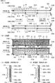
ここで、第1演出装置300について、図3及び図4に基づいて説明する。図3は、(A)は枠側ユニット及び盤側ユニットを示す平面図、(B)は枠側ユニット及び盤側ユニットを示す正面図、(C)は枠側演出体を示す縦断面図、(D)は盤側演出体を示す断面図である。図4は、パチンコ遊技機の上部における内部機構を示す概略縦断面図である。
Here, the
図3及び図4に示すように、第1演出装置300は、正面視横長四角形状に形成された3つの枠側演出体301A,301B,301Cと、3つのうち2つの枠側演出体301B,301Cを駆動するための駆動機構302と、枠側演出体301B,301Cの位置を検出するための枠側演出体位置センサ330A〜330Eと、枠側発光部9Hを構成する複数の演出用LED9が前面に設けられたLED基板9Aと、を有する枠側演出体ユニット300Aと、正面視横長四角形状に形成された3つの盤側演出体311A,311B,311Cと、3つのうち2つの盤側演出体311B,311Cを駆動するための駆動機構312と、盤側演出体311B,311Cの位置を検出するための盤側演出体位置センサ340A〜340Eと、を有する盤側演出体ユニット300Bと、から主に構成される。
As shown in FIGS. 3 and 4, the
枠側演出体301A,301B,301C及び盤側演出体311A,311B,311Cは、各々の正面視形状は全て同形状をなし、非透光性部材からなるベース部材370と、ベース部材370の前面側に該前面を被覆するように取付けられるカバー部材371と、から構成され、内部には、複数の枠側文字用LED350A,350B,350C、盤側文字用LED360A,360B,360Cが前方に光を照射可能に設けられたLED基板と、複数の枠側背景用LED351A,351B,351C、盤側背景用LED361A,361B,361Cが前方に光を照射可能に設けられたLED基板と、が内蔵されている。
The frame-
カバー部材371の前面には、光を透過可能な透過性部材からなる第1演出部372A、第2演出部372Bが設けられている。第1演出部372A、第2演出部372Bは、枠側文字用LED350A,350B,350C、盤側文字用LED360A,360B,360Cからの光が出射される第1領域Z1と、枠側背景用LED351A,351B,351C、盤側背景用LED361A,361B,361Cからの光が出射される第2領域Z2と、を有している。尚、枠側文字用LED350A,350B,350C、盤側文字用LED360A,360B,360Cと枠側背景用LED351A,351B,351C、盤側背景用LED361A,361B,361Cとは遮光性部材により仕切られており、第1領域Z1と第2領域Z2とを個別に発光させることができるようになっている。
On the front surface of the
また、枠側演出体301Aの第1領域Z1は「熱」の文字の上部、盤側演出体311Aの第1領域Z1は「熱」の文字の下部、枠側演出体301Bの第1領域Z1は「激」の文字の上部、盤側演出体311Bの第1領域Z1は「激」の文字の下部、枠側演出体301Cの第1領域Z1は「超」の文字の上部、盤側演出体311Cの第1領域Z1は「超」の文字の下部を各々模った形状とされている。
Further, the first area Z1 of the frame
盤側演出体311Aは、盤側演出体ユニット300Bの右側に移動不能に立設されている。盤側演出体311Aの後側には、盤側演出体311Bが、盤側演出体311Aの背面側に位置する第1位置(原点位置)と、第1位置よりも左側の第2位置と、の間で左右方向に移動可能に立設されている。さらに、盤側演出体311Bの後側には、盤側演出体311Cが、盤側演出体311Aの背面側に位置する第1位置(原点位置)と、第2位置よりもさらに左側の第3位置と、の間で左右方向に移動可能に立設されている。
The board-
枠側演出体301Aは、枠側演出体ユニット300Aの右側に移動不能に立設されている。枠側演出体301Aの後側には、枠側演出体301Bが、枠側演出体301Aの背面側に位置する第1位置(原点位置)と、枠側演出体301Aの左側に位置し盤側演出体311Bの第2位置に対応する第2対応位置と、の間で左右方向に移動可能に立設されている。さらに、枠側演出体301Bの後側には、枠側演出体301Cが、枠側演出体301Aの背面側に位置する第1位置(原点位置)と、第2対応位置よりもさらに左側であって盤側演出体311Cの第3位置に対応する第3対応位置と、の間で左右方向に移動可能に立設されている。
The frame-
尚、本実施例では、枠側演出体301Bが第2位置及び盤側演出体311Bが第2対応位置に移動した状態においてパチンコ遊技機1を正面側の所定の視点位置から視たときに、枠側演出体301B及び盤側演出体311Bの右側辺部と枠側演出体301A及び盤側演出体311Aの左側辺部とが僅かに重畳し、枠側演出体301C及び盤側演出体311Cが第3位置及び第3対応位置に移動した状態においてパチンコ遊技機1を正面側の所定の視点位置から視たときに、枠側演出体301C及び盤側演出体311Cの右側辺部と枠側演出体301B及び盤側演出体311Bの左側辺部とが僅かに重畳するようになっているが、互いの側辺部が左右方向のほぼ同位置に配置されてもよいし、互いに離れた位置に配置されてもよい。
In this embodiment, when the pachinko gaming machine 1 is viewed from a predetermined viewpoint position on the front side in a state where the
枠側演出体ユニット300Aの駆動機構302は、枠側演出体301Bを駆動するための枠側演出体用モータ310Aと、枠側演出体ユニット300Aの下部に左右方向に延設され枠側演出体用モータ310Aにより軸心周りに回動する駆動軸375Aと、駆動軸375Aの上方に左右方向に延設される案内軸376Aと、枠側演出体301Cを駆動するための枠側演出体用モータ310Bと、枠側演出体ユニット300Aの下部における駆動軸375Aの後側に左右方向に延設され枠側演出体用モータ310Bにより軸心周りに回動する駆動軸375Bと、駆動軸375Bの上方に左右方向に延設される案内軸376Bと、を有する。
The
駆動軸375A,375Bは、枠側演出体301B,301C各々のベース部材370の下部に左右方向に形成された貫通孔に挿入され、案内軸376A,376Bは、枠側演出体301B,301C各々のベース部材370の上部に左右方向に形成された貫通孔に挿入されており、枠側演出体301B,301Cは、これら駆動軸375A,375Bと案内軸376A,376Bとにより立設した状態で左右方向に移動可能に支持されている。また、駆動軸375A,375Bの周面には凹状の溝部(図示略)が螺旋状に形成されており、該溝部には、枠側演出体301B,301C各々のベース部材370の下部に左右方向に形成された貫通孔の内周面に形成された係止部(図示略)が係止されている。よって、枠側演出体301B,301Cは、枠側演出体用モータ310A,310Bにより駆動軸375A,375Bが正逆回動することで左右方向に移動する。
The
盤側演出体ユニット300Bの駆動機構312は、盤側演出体311Bを駆動するための盤側演出体用モータ320Aと、盤側演出体ユニット300Bの下部に左右方向に延設され盤側演出体用モータ320Aにより軸心周りに回動する駆動軸385Aと、駆動軸385Aの上方に左右方向に延設される案内軸386Aと、盤側演出体311Cを駆動するための盤側演出体用モータ320Bと、盤側演出体ユニット300Bの下部における駆動軸385Aの後側に左右方向に延設され盤側演出体用モータ320Bにより軸心周りに回動する駆動軸385Bと、駆動軸385Bの上方に左右方向に延設される案内軸386Bと、を有する。
The drive mechanism 312 of the board-
駆動軸385A,385Bは、盤側演出体311B,311C各々のベース部材370の下部に左右方向に形成された貫通孔に挿入され、案内軸386A,386Bは、盤側演出体311B,311C各々のベース部材370の上部に左右方向に形成された貫通孔に挿入されており、盤側演出体311B,311Cは、これら駆動軸385A,385Bと案内軸386A,386Bとにより立設した状態で左右方向に移動可能に支持されている。また、駆動軸385A,385Bの周面には凹状の溝部(図示略)が螺旋状に形成されており、該溝部には、盤側演出体311B,311C各々のベース部材370の下部に左右方向に形成された貫通孔の内周面に形成された係止部(図示略)が係止されている。よって、盤側演出体311B,311Cは、盤側演出体用モータ320A,320Bにより駆動軸385A,385Bが正逆回動することで左右方向に移動する。
The
また、駆動軸375A,375B、385A,385B各々の下方には、枠側演出体301B,301C及び盤側演出体311B,311Cの下面における左端部から突出する被検出片315を検出可能な枠側演出体位置センサ330A〜330E及び盤側演出体位置センサ340A〜340Eが設けられている。詳しくは、枠側演出体位置センサ330A,330C及び盤側演出体位置センサ340A,340Cは、枠側演出体301B,301C及び盤側演出体311B,311Cが第1位置に位置しているか否かを検出するセンサであり、枠側演出体位置センサ330B,330D及び盤側演出体位置センサ340B,340Dは、枠側演出体301B,301C及び盤側演出体311B,311Cが第2位置に位置しているか否かを検出するセンサであり、枠側演出体位置センサ330E及び盤側演出体位置センサ340Eは、枠側演出体301B,301C及び盤側演出体311B,311Cが第3位置に位置しているか否かを検出するセンサであり、これら枠側演出体位置センサ330A〜330E及び盤側演出体位置センサ340A〜340Eは演出制御基板12に接続されている。
Further, below each of the
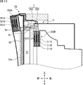
図4に示すように、枠側演出体ユニット300Aは、ガラス扉枠50の上部に設けられ、盤側演出体ユニット300Bは、遊技機用枠3における遊技盤2の盤面板200の上部背面側に設けられている。詳しくは、盤側演出体ユニット300Bは、枠側演出体ユニット300Aに対し下方かつ後方にずれた位置に配置されているが、盤側演出体ユニット300Bの上端と枠側演出体ユニット300Aの下端とは上下方向のほぼ同じ位置に配置されている。つまり、枠側演出体ユニット300Aと盤側演出体ユニット300Bとは、前後方向及び上下方向の異なる位置(互いに重複しない位置)に配置されているが、パチンコ遊技機1を正面側の所定の視点位置から視たときに、盤側演出体ユニット300Bの上端が枠側演出体ユニット300Aの下端に近接して見えるように配置されている(図1参照)。
As shown in FIG. 4, the frame
さらに、枠側演出体ユニット300Aの右側に固定された枠側演出体301Aの直下に、盤側演出体ユニット300Bの右側に固定された盤側演出体311Aが近接して配置されることで、パチンコ遊技機1を正面側の所定の視点位置から視たときに、枠側演出体301Aと盤側演出体311Aの第1領域Z1により「熱」の文字が形成される。また、枠側演出体301Bと枠側演出体301Bとが各々第2位置に移動した場合、枠側演出体301Bの直下に盤側演出体311Bが近接して配置されることで、パチンコ遊技機1を正面側の所定の視点位置から視たときに、枠側演出体301Bと盤側演出体311Bの第1領域Z1により「激」の文字が形成される。また、枠側演出体301Bと枠側演出体301Bとが各々第3位置に移動した場合、枠側演出体301Cの直下に盤側演出体311Cが近接して配置されることで、パチンコ遊技機1を正面側の所定の視点位置から視たときに、枠側演出体301Cと盤側演出体311Cの第1領域Z1により「超」の文字が形成される。
Furthermore, the board-
このように構成される第1演出装置300は、後述する可動演出を行っていない状態において、枠側演出体301B,301C及び盤側演出体311B,311Cが第1位置(原点位置)にあるため、枠側演出体301Aと盤側演出体311Aの第1領域Z1からなる「熱」の文字と、その左側の枠側発光部9Hとが視認可能である(図24(A)参照)。また、後述する可動演出において、枠側演出体301Bと枠側演出体301Bとが各々第2位置に移動した場合は、枠側演出体301A,301Bと盤側演出体311A,311Bの第1領域Z1からなる「激熱」の文字が視認可能となる一方、枠側発光部9Hの右半部が視認不能となる。また、枠側演出体301Bと枠側演出体301Bとが各々第2位置に移動し、かつ、枠側演出体301Cと枠側演出体301Cとが各々第3位置に移動した場合、枠側演出体301A,301B,301Cと盤側演出体311A,311B,311Cの第1領域Z1からなる「超激熱」の文字が視認可能となる一方、枠側発光部9Hの全域が視認不能となる。
In the
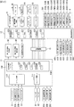
パチンコ遊技機1には、例えば、図2に示すような主基板11、演出制御基板12、音声制御基板13、LED制御基板14といった、各種の制御基板が搭載されている。また、パチンコ遊技機1には、主基板11と演出制御基板12との間で伝送される各種の制御信号を中継するための中継基板15なども搭載されている。その他にも、遊技盤2などの背面には、例えば払出制御基板、情報端子基板、発射制御基板、インタフェース基板、電源基板などといった、各種の基板が配置されている。
The pachinko gaming machine 1 is equipped with various control boards such as a main board 11, an
主基板11は、メイン側の制御基板であり、パチンコ遊技機1での遊技の進行を制御するための各種回路が搭載されている。主基板11は、主として、特図ゲームにて用いる乱数の設定機能、所定位置に配設されたスイッチ等からの出力信号を入力可能とする機能、演出制御基板12などからなるサブ側の制御基板に宛てて、指令情報の一例となる制御コマンドを制御信号として出力して送信する機能、外部に各種情報を出力する機能などを備えている。また、主基板11は、第1特別図柄表示器4Aと第2特別図柄表示器4Bを構成する各LED(例えばセグメントLED)などの点灯/消灯制御を行って第1特図や第2特図の変動表示を制御することや、普通図柄表示器20の点灯/消灯/発色制御などを行って普通図柄表示器20による普通図柄の変動表示を制御することといった、所定の表示図柄の変動表示を制御する機能も備えている。
The main board 11 is a main-side control board on which various circuits for controlling the progress of the game in the pachinko gaming machine 1 are mounted. The main board 11 is a sub-side control board mainly composed of a random number setting function used in a special figure game, a function that allows an output signal from a switch or the like disposed at a predetermined position to be input, and an
主基板11には、例えば遊技制御用マイクロコンピュータ100や、遊技球検出用の各種スイッチからの検出信号を取り込んで遊技制御用マイクロコンピュータ100に伝送するスイッチ回路110、遊技制御用マイクロコンピュータ100からのソレノイド駆動信号をソレノイド81,82に伝送するソレノイド回路111などが搭載されている。
The main board 11 includes, for example, a
演出制御基板12は、主基板11とは独立したサブ側の制御基板であり、中継基板15を介して主基板11から伝送された制御信号を受信して、演出表示装置5、スピーカ8L,8R及び演出用LED9といった演出用の電気部品による演出動作を制御するための各種回路が搭載されている。即ち、演出制御基板12は、演出表示装置5の表示動作や、第1演出装置300の枠側演出体301B,301Cや盤側演出体311B,311Cを駆動する枠側演出体用モータ310A,310B、盤側演出体用モータ320A,320B、第2演出装置400の可動体401を駆動する第2可動体用モータ410及び第3演出装置500の可動体501を駆動する第3可動体用モータ510の動作制御や、スピーカ8L,8Rからの音声出力動作の全部または一部、演出用LED9、可動体401に内蔵された第2可動体用LED450、可動体501に内蔵された第3可動体用LED550などの点灯/消灯動作の全部または一部といった、演出用の電気部品に所定の演出動作を実行させるための制御内容を決定する機能を備えている。尚、中継基板15を有しない構成としても良い。
The
音声制御基板13は、演出制御基板12とは別個に設けられた音声出力制御用の制御基板であり、演出制御基板12からの指令や制御データ(音番号や音量レベル等)などに基づき、スピーカ8L,8Rから音声を出力させるための音声信号処理を実行する処理回路などが搭載されている。LED制御基板14は、演出制御基板12とは別個に設けられたLED出力制御用の制御基板であり、演出制御基板12からの指令や制御データなどに基づき、演出用LED9などの点灯/消灯駆動を行うLEDドライバ回路などが搭載されている。
The
図2に示すように、主基板11には、ゲートスイッチ21、第1始動口スイッチ22A、第2始動口スイッチ22B、カウントスイッチ23からの検出信号を伝送する配線が接続されている。尚、ゲートスイッチ21、第1始動口スイッチ22A、第2始動口スイッチ22B、カウントスイッチ23は、例えばセンサと称されるものなどのように、遊技球を検出できる任意の構成を有するものであればよい。また、主基板11には、第1特別図柄表示器4A、第2特別図柄表示器4B、普通図柄表示器20、第1保留表示器25A、第2保留表示器25B、普図保留表示器25Cなどの表示制御を行うための指令信号を伝送する配線が接続されている。
As shown in FIG. 2, wiring for transmitting detection signals from the
主基板11から演出制御基板12に向けて伝送される制御信号は、中継基板15によって中継される。中継基板15を介して主基板11から演出制御基板12に対して伝送される制御コマンドは、例えば電気信号として送受信される演出制御コマンドである。
A control signal transmitted from the main board 11 toward the
本実施例で用いられる演出制御コマンドは、例えば2バイト構成であり、1バイト目はMODE(コマンドの分類)を示し、2バイト目はEXT(コマンドの種類)を表す。尚、以下に説明するコマンドは一例であって、他のコマンド形態を用いてもよい。ここで、XXHは不特定の16進数であることを示し、演出制御コマンドによる指示内容に応じた値であればよい。 The effect control command used in the present embodiment has, for example, a 2-byte configuration. The first byte indicates MODE (command classification), and the second byte indicates EXT (command type). Note that the commands described below are merely examples, and other command forms may be used. Here, XXH indicates an unspecified hexadecimal number and may be a value corresponding to the instruction content by the effect control command.
コマンド8001Hは、第1特別図柄表示器4Aでの変動開始を指定する第1変動開始コマンドである。コマンド8002Hは、第2特別図柄表示器4Bでの変動開始を指定する第2変動開始コマンドである。コマンド81XXHは、変動パターン(変動時間)を指定する変動パターン指定コマンドであり、指定する変動パターンなどに応じて、異なるEXTデータが設定される。
The command 8001H is a first change start command that specifies the start of change in the first
コマンド8CXXHは、変動表示結果通知コマンドであり、変動表示結果を指定する演出制御コマンドである。尚、コマンド8C00Hは、「はずれ」となる旨の事前決定結果を示すコマンドである。コマンド8C01Hは、「大当り」で大当り種別が「確変大当りA」となる旨を通知するコマンドである。コマンド8C02Hは、「大当り」で大当り種別が「確変大当りB」となる旨を通知するコマンドである。コマンド8C03Hは、「大当り」で大当り種別が「非確変大当り」となる旨を通知するコマンドである。 The command 8CXXH is a change display result notification command, and is an effect control command for designating the change display result. Note that the command 8C00H is a command indicating a pre-determined result indicating that it is “off”. The command 8C01H is a command for notifying that the big hit type is “big hit big hit A”. The command 8C02H is a command for notifying that “big hit” is the big hit type and “probable big hit B”. The command 8C03H is a command for notifying that the big hit type is “big hit” and the big hit type is “non-probable big hit”.
コマンド8F00Hは、演出図柄の変動停止(確定)を指定する図柄確定コマンドである。コマンド95XXHは、その時点の遊技状態を指定する遊技状態指定コマンドである。コマンドA0XXHは、大当り遊技状態の開始を指定する大当り開始指定コマンド(「ファンファーレコマンド」ともいう)である。コマンドA1XXHは、大当り遊技状態にて、大入賞口が開放状態となったこと及び大入賞口が開放状態である期間であることを通知する大入賞口開放中通知コマンドである。コマンドA2XXHは、大当り遊技状態にて、大入賞口が開放状態から閉鎖状態となったこと及び大入賞口が閉鎖状態である期間であることを通知する大入賞口開放後通知コマンドである。コマンドA3XXHは、大当り遊技状態の終了を指定する大当り終了指定コマンドである。尚、大入賞口開放中通知コマンドや大入賞口開放後通知コマンドでは、例えば通常開放大当り状態や短期開放大当り状態のラウンドの実行回数(例えば「1」〜「16」または「1」〜「5」)に対応したEXTデータが設定される。 The command 8F00H is a symbol confirmation command for designating the stop of variation (determination) of the effect symbol. The command 95XXH is a gaming state designation command that designates the gaming state at that time. The command A0XXH is a jackpot start designation command (also referred to as a “fanfare command”) that designates the start of a jackpot gaming state. The command A1XXH is a big prize opening open notification command for notifying that the big prize opening is in an open state and that the big prize opening is in an open state in the big hit gaming state. The command A2XXH is a notification command after opening the big prize opening notifying that the big prize opening has been changed from the open state to the closed state and that the big prize opening is in the closed state in the big hit gaming state. Command A3XXH is a jackpot end designation command for designating the end of the jackpot gaming state. It should be noted that the notification command during the opening of the big prize opening or the notification command after the big prize opening is opened, for example, the number of rounds executed in the normal opening big hit state or the short-term opening big hit state (for example, “1” to “16” or “1” to “5”). EXT data corresponding to ")" is set.
コマンドB100Hは、普通入賞球装置6Aが形成する第1始動入賞口への入賞によって第1始動条件が成立したことを通知する第1始動口入賞指定コマンドである。コマンドB200Hは、普通可変入賞球装置6Bが形成する第2始動入賞口への入賞によって第2始動条件が成立したことを通知する第2始動口入賞指定コマンドである。コマンドC1XXHは、第1特図保留記憶数を通知する第1保留記憶数通知コマンドである。コマンドC2XXHは、第2特図保留記憶数を通知する第2保留記憶数通知コマンドである。
The command B100H is a first start port winning designation command for notifying that the first start condition has been established by winning a first start winning port formed by the normal
主基板11に搭載された遊技制御用マイクロコンピュータ100は、例えば1チップのマイクロコンピュータであり、遊技制御用のプログラムや固定データ等を記憶するROM101(Read only Memory 101)と、遊技制御用のワークエリアを提供するRAM102(Random Access Memory 102)と、遊技制御用のプログラムを実行して制御動作を行うCPU103(Central Processing Unit 103)と、CPU103とは独立して乱数値を示す数値データの更新を行う乱数回路104と、I/O105(Input/Outputport 105)とを備えて構成される。
The
一例として、遊技制御用マイクロコンピュータ100では、CPU103がROM101から読み出したプログラムを実行することにより、遊技の進行を制御するための各種処理が実行される。
As an example, in the
主基板11では、特図表示結果判定用の乱数値MR1、大当り種別判定用の乱数値MR2、変動パターン判定用の乱数値MR3、普図表示結果判定用の乱数値MR4等の各種乱数値の数値データが、カウント可能に制御される。尚、乱数回路104は、これらの乱数値MR1〜MR4の一部または全部を示す数値データをカウントできるものであればよく、乱数回路104にてカウントしない乱数値については、CPU103が、ソフトウェアによって各種の数値データを更新することでカウントするようにすればよい。
In the main board 11, various random number values such as a random value MR1 for determining a special figure display result, a random value MR2 for determining a jackpot type, a random value MR3 for determining a variation pattern, a random value MR4 for determining a normal figure display result, etc. Numerical data is controlled to be countable. The
本実施例では、複数の変動パターンが予め用意されている。具体的に、本実施例では、変動表示結果が「はずれ」となる場合のうち、演出図柄の変動表示態様が「非リーチ」である場合と「リーチ」である場合のそれぞれに対応して、また、変動表示結果が「大当り」となる場合などに対応して、複数の変動パターンが予め用意されている。 In this embodiment, a plurality of variation patterns are prepared in advance. Specifically, in the present embodiment, among the cases where the variation display result is “out of”, corresponding to each of the case where the variation display mode of the production symbol is “non-reach” and “reach”, A plurality of variation patterns are prepared in advance in response to a case where the variation display result is “big hit”.
変動表示結果が「大当り」である場合に対応した変動パターンである大当り変動パターンや、演出図柄の変動表示態様が「リーチ」である場合のリーチ変動パターンには、ノーマルリーチのリーチ演出が実行されるノーマルリーチ変動パターンと、スーパーリーチα、スーパーリーチβといったスーパーリーチのリーチ演出が実行されるスーパーリーチ変動パターンとがある。尚、本実施例では、ノーマルリーチ変動パターンを1種類のみしか設けていないが、本発明はこれに限定されるものではなく、スーパーリーチと同様に、ノーマルリーチα、ノーマルリーチβ、…のように、複数のノーマルリーチ変動パターンを設けても良い。また、スーパーリーチ変動パターンでも、スーパーリーチαやスーパーリーチβに加えてスーパーリーチγ…といった3以上のスーパーリーチ変動パターンを設けても良い。 The reach effect of normal reach is executed for the jackpot variation pattern, which is a variation pattern corresponding to the case where the variation display result is “big hit”, and the reach variation pattern when the variation display mode of the effect design is “reach”. There are a normal reach fluctuation pattern and a super reach fluctuation pattern in which a reach expression of super reach such as super reach α and super reach β is executed. In this embodiment, only one type of normal reach variation pattern is provided. However, the present invention is not limited to this, and a plurality of normal reach α, normal reach β,... The normal reach fluctuation pattern may be provided. Also, in the super reach variation pattern, three or more super reach variation patterns such as super reach γ... In addition to super reach α and super reach β may be provided.
本実施例におけるノーマルリーチのリーチ演出が実行されるノーマルリーチ変動パターンの特図変動時間については、スーパーリーチ変動パターンであるスーパーリーチα、スーパーリーチβよりも短く設定されている。また、本実施例におけるスーパーリーチα、スーパーリーチβといったスーパーリーチのリーチ演出が実行されるスーパーリーチ変動パターンの特図変動時間については、スーパーリーチβのスーパーリーチ演出が実行される変動パターンの方が、スーパーリーチαのスーパーリーチ演出が実行される変動パターンよりも特図変動時間が長く設定されている。 The special figure fluctuation time of the normal reach fluctuation pattern in which the reach effect of the normal reach in the present embodiment is set shorter than the super reach α and super reach β that are the super reach fluctuation patterns. In addition, regarding the special figure variation time of the super reach variation pattern in which super reach reach production such as super reach α and super reach β in this embodiment is performed, the variation pattern in which super reach β super reach production is performed. However, the special figure variation time is set longer than the variation pattern in which the super reach production of the super reach α is executed.
尚、本実施例では、スーパーリーチβ、スーパーリーチα、ノーマルリーチの順に変動表示結果が「大当り」となる大当り期待度(大当り信頼度)が高くなるように設定されているため、ノーマルリーチ変動パターン及びスーパーリーチ変動パターンにおいては変動時間が長いほど大当り期待度(大当り信頼度)が高くなっている。また、本実施例では、大当りとなる場合に、必ずリーチ状態となってスーパーリーチβ、スーパーリーチα、ノーマルリーチのいずれかが実行されるようになっているが、本発明はこれに限定されるものではなく、非リーチの変動パターンでも大当りとなる場合があるようにしてもよい。 In this embodiment, since the big hit expectation (big hit reliability) that the fluctuation display result is “big hit” is set in the order of super reach β, super reach α, and normal reach, the normal reach fluctuation pattern and In the super reach variation pattern, the longer the variation time, the higher the jackpot expectation (hit hit reliability). Further, in this embodiment, when a big hit is made, the reach state is always set and any one of the super reach β, the super reach α, and the normal reach is executed, but the present invention is limited to this. It may be a big hit even with a non-reach fluctuation pattern.
図2に示す遊技制御用マイクロコンピュータ100が備えるROM101には、ゲーム制御用のプログラムの他にも、遊技の進行を制御するために用いられる各種の選択用データ、テーブルデータなどが格納されている。例えば、ROM101には、CPU103が各種の判定や決定、設定を行うために予め用意された複数の判定テーブルや設定テーブルなどを構成するデータが記憶されている。また、ROM101には、CPU103が主基板11から各種の制御コマンドとなる制御信号を送信するために用いられる複数のコマンドテーブルを構成するテーブルデータや、変動パターンを複数種類格納する変動パターンテーブルを構成するテーブルデータなどが、記憶されている。
In addition to the game control program, the
ROM101に記憶される表示結果判定テーブルは、第1特別図柄表示器4Aや第2特別図柄表示器4Bの特図ゲームにおいて確定特別図柄が導出表示される前に、その変動表示結果を「大当り」として大当り遊技状態に制御するか否かを、乱数値MR1に基づいて決定するために参照されるテーブルである。
The display result determination table stored in the
本実施例の表示結果判定テーブルでは、遊技状態が通常状態または時短状態(低確状態)であるか、確変状態(高確状態)であるかに応じて、乱数値MR1と比較される数値(判定値)が、「大当り」や「はずれ」の特図表示結果に割り当てられている。 In the display result determination table of the present embodiment, a numerical value (compared to the random value MR1 depending on whether the gaming state is the normal state, the short time state (low probability state), or the probability variation state (high probability state) ( (Judgment value) is assigned to the special figure display result of “big hit” or “out of place”.
表示結果判定テーブルでは、特図表示結果を「大当り」として大当り遊技状態に制御するか否かの決定結果に対して判定用データが割り当てられている。具体的に、本実施例では、遊技状態が確変状態(高確状態)であるときに、通常状態または時短状態(低確状態)であるときよりも多くの判定値が、「大当り」の特図表示結果に割り当てられている。これにより、確変制御が行われる確変状態(高確状態)では、通常状態または時短状態(低確状態)であるときに特図表示結果を「大当り」として大当り遊技状態に制御すると決定される確率(本実施例では約1/300)に比べて、特図表示結果を「大当り」として大当り遊技状態に制御すると決定される確率が高くなる(本実施例では約1/30)。即ち、表示結果判定テーブルでは、遊技状態が確変状態(高確状態)であるときに、通常状態や時短状態であるときに比べて大当り遊技状態に制御すると決定される確率が高くなるように、判定用データが大当り遊技状態に制御するか否かの決定結果に割り当てられている。 In the display result determination table, determination data is assigned to a determination result as to whether or not to control the big hit gaming state with the special figure display result as “big hit”. Specifically, in the present embodiment, when the gaming state is the probability variation state (high probability state), more judgment values than the normal state or the short time state (low probability state) are characteristic of “big hit”. Assigned to diagram display results. With this, in the probability variation state (high probability state) in which probability variation control is performed, the probability that the special figure display result will be determined to be “big hit” and controlled to the big hit gaming state in the normal state or the short time state (low probability state) Compared to (about 1/300 in the present embodiment), the probability that the special figure display result is determined to be “big hit” and controlled to the big hit gaming state becomes higher (about 1/30 in the present embodiment). That is, in the display result determination table, when the gaming state is a probability change state (high probability state), the probability that it is determined to control to the big hit gaming state is higher than when the gaming state is a normal state or a short time state. The determination data is assigned to the determination result of whether or not to control the big hit gaming state.
尚、ROM101には、大当り遊技状態に制御すると決定されたときに、乱数値MR2に基づき、大当り種別を複数種類のいずれかに決定するために参照される大当り種別判定テーブルや、乱数値MR3に基づいて変動パターンを、前述した変動パターンのいずれかに決定するための変動パターン判定テーブルも記憶されている。
In the
設定例として、変動特図が第1特図であるか第2特図であるかに応じて、「確変大当りA」と「確変大当りB」の大当り種別に対する判定値の割当てが異なっている。つまり、変動特図が第2特図である場合には、ラウンド数の少ない「確変大当りB」の大当り種別に割当てがなく、第2特図の変動表示では「確変大当りB」が発生しないようにすることで、時短制御に伴う高開放制御により、普通可変入賞球装置6Bが形成する第2始動入賞口に遊技球が進入しやすい遊技状態中に、得られる賞球が少ない「確変大当りB」が頻発して遊技興趣が低下してしまうことを防止できるようになっている。
As a setting example, the allocation of the judgment value to the big hit types of “probability variation big hit A” and “probability big hit B” differs depending on whether the variation special chart is the first special chart or the second special chart. That is, when the fluctuation special chart is the second special figure, there is no allocation to the big hit type of “probability big hit B” with a small number of rounds, and “probability big hit B” does not occur in the fluctuation display of the second special figure. Therefore, the number of prize balls obtained is small in the gaming state in which the game balls are likely to enter the second starting prize opening formed by the normally variable prize-winning
また、ROM101に記憶されている変動パターン判定テーブルとしては、「大当り」とすることが事前決定されたときに使用される大当り用変動パターン判定テーブルと、「はずれ」にすることが事前決定されたときに使用されるはずれ用変動パターン判定テーブルとが予め用意されている。尚、本実施例では、はずれのときよりも大当りとなるときの方がリーチの変動パターンが決定されやすくなり、リーチが発生した場合の方が大当りになる可能性(信頼度や期待度)が高くなるとともに、同じリーチの変動パターンであっても、ノーマルリーチよりもスーパーリーチの方が大当りになる可能性(信頼度や期待度)が高く、同じスーパーリーチであってもスーパーリーチβの変動パターンの方が、確変大当りになる可能性(信頼度や期待度)が高くなるように、大当り用変動パターン判定テーブルとはずれ用変動パターン判定テーブルにおいて、各変動パターンに対応する判定値が設定されている。
The variation pattern determination table stored in the
尚、はずれ用変動パターン判定テーブルは、合計保留記憶数や時短状態に対応した複数のテーブルを含んでおり、保留記憶数や時短状態に応じて、合計保留記憶数が2〜4個に対応する短縮の非リーチはずれの変動パターン(PA1−2)や、合計保留記憶数が5〜8個に対応する短縮の非リーチはずれの変動パターン(PA1−3)や、短縮の非リーチはずれの変動パターン(PA1−4)を、合計保留記憶数や遊技状態(時短状態)に応じて決定することで、合計保留記憶数が多くなる程、短い変動パターンが実行され易い、つまり、単位時間当りの変動回数が高まることで、無駄な始動入賞の発生を防ぐことが可能であるとともに、時短制御中(時短状態中)では、時短制御が実行されていないときよりも、短縮の非リーチはずれの変動パターン(PA1−4)が多く決定されて単位時間当りの変動回数が高まることで、次の大当りまでの期間を短縮でき、遊技者の連荘感を向上できるようになっている。 The variation pattern determination table for loss includes a plurality of tables corresponding to the total number of reserved memories and the short time state, and the total number of reserved memories corresponds to 2 to 4 according to the number of reserved memories and the short time state. Short non-reach shift variation pattern (PA1-2), short non-reach shift variation pattern (PA1-3) corresponding to a total number of pending storages of 5 to 8, and short non-reach shift variation pattern By determining (PA1-4) according to the total number of reserved memories and the gaming state (short time state), the larger the total number of reserved memories, the easier the short variation pattern is executed, that is, the fluctuation per unit time By increasing the number of times, it is possible to prevent the occurrence of useless start winnings, and during non-time control (during short-time state), the non-reach deviation of the shortening changes more than when the time control is not executed. Pattern (PA1-4) that is often determined by increasing the number of times of the change per unit time, can reduce the time to the next jackpot, and to be able to improve the extended game player's sense of.
図2に示す遊技制御用マイクロコンピュータ100が備えるRAM102は、その一部または全部が所定の電源基板からのバックアップ電源によってバックアップされているバックアップRAMであればよい。すなわち、パチンコ遊技機1に対する電力供給が停止しても、所定期間(バックアップ電源としてのコンデンサが放電してバックアップ電源が電力供給不能になるまで)は、RAM102の一部または全部の内容は保存され、再度の電源投入にて、遊技状態すなわち遊技制御手段の制御状態に応じたデータ(特図プロセスフラグなど)と未払出賞球数を示すデータ等の遊技の進行状態を示すデータを引き継ぐようにすればよい。
The
このようなRAM102には、遊技の進行などを制御するために用いられる各種のデータを保持する領域として、図示しない遊技制御用データ保持エリアが設けられている。遊技制御用データ保持エリアは、普通入賞球装置6Aが形成する第1始動入賞口を遊技球が通過(進入)して始動入賞(第1始動入賞)が発生したものの未だ開始されていない第1特図を用いた特図ゲームの保留データとして、乱数値MR1、乱数値MR2、乱数値MR3を示す数値データなどを記憶する第1特図保留記憶部と、普通可変入賞球装置6Bが形成する第2始動入賞口を遊技球が通過(進入)して始動入賞(第2始動入賞)が発生したものの未だ開始されていない第2特図を用いた特図ゲームの保留データとして、乱数値MR1、乱数値MR2、乱数値MR3を示す数値データなどを記憶する第2特図保留記憶部と、普図保留記憶部と、特図プロセスフラグ等の遊技の進行状況などに応じて状態を更新可能な複数種類のフラグが設けられている遊技制御フラグ設定部と、遊技の進行を制御するために用いられる各種のタイマが設けられている遊技制御タイマ設定部と、遊技の進行を制御するために用いられるカウント値を計数するための複数種類のカウンタが設けられている遊技制御カウンタ設定部と、遊技の進行を制御するために用いられるデータを一時的に記憶する各種のバッファが設けられている遊技制御バッファ設定部とを備えている。
In such a
図2に示すように、演出制御基板12には、プログラムに従って制御動作を行う演出制御用CPU120と、演出制御用のプログラムや固定データ等を記憶するROM121と、演出制御用CPU120のワークエリアを提供するRAM122と、演出表示装置5での表示動作の制御内容を決定するための処理などを実行する表示制御部123と、演出制御用CPU120とは独立して乱数値を示す数値データの更新を行う乱数回路124と、I/O125とが搭載されている。
As shown in FIG. 2, the
一例として、演出制御基板12では、演出制御用CPU120がROM121から読み出した演出制御用のプログラムを実行することにより、演出用の電気部品による演出動作を制御するための各種処理が実行される。例えば、これら演出動作を制御するための処理として、演出制御用CPU120がI/O125を介して演出制御基板12の外部から各種信号の入力を受け付ける受信処理、演出制御用CPU120がI/O125を介して演出制御基板12の外部へと各種信号を出力する送信処理なども行われる。
As an example, in the
尚、演出制御基板12の側でも、主基板11と同様に、例えば、各種演出の実行、非実行や、演出の種別等を決定するための各種の乱数値(演出用乱数ともいう)が設定されている。また、ROM121には、演出制御用のプログラムの他にも、第1演出装置300の枠側演出体301B,301Cや盤側演出体311B,311C、第2演出装置400の可動体401及び第3演出装置500の可動体501の動作を含む演出動作を制御するために用いられる各種のテーブルデータ、例えば、各種演出の実行、非実行や、演出の種別等を決定するための複数の判定テーブルを構成するテーブルデータ、各変動パターンに対応する演出制御パターンを構成するパターンデータなどが記憶されている。
Note that, on the side of the
演出制御パターンのうち、特図変動時演出制御パターンは、各変動パターンに対応して、特別図柄の変動が開始されてから確定特別図柄が導出表示されるまでの期間における、演出図柄の変動表示動作や各可動体(第1演出装置300の枠側演出体301B,301Cや盤側演出体311B,311C、第2演出装置400の可動体401及び第3演出装置500の可動体501)を動作させるリーチ演出等の様々な演出動作の制御内容を示すデータなどから構成されている。
Among the effect control patterns, the effect control pattern at the time of special symbol variation displays the variation of the effect symbol during the period from the start of the variation of the special symbol until the finalized special symbol is derived and displayed corresponding to each variation pattern. Operation and operation of each movable body (frame
また、RAM122には、演出動作を制御するために用いられる各種データを保持する領域として、例えば図示しない演出制御用データ保持エリアが設けられている。演出制御用データ保持エリアは、演出動作状態や主基板11から送信された演出制御コマンド等に応じて状態を更新可能な複数種類のフラグが設けられている演出制御フラグ設定部と、各種演出動作の進行を制御するために用いられる複数種類のタイマやカウンタが設けられている演出制御タイマ設定部や演出制御カウンタ設定部と、各種演出動作の進行を制御するために用いられるデータを一時的に記憶する各種のバッファが設けられている演出制御バッファ設定部とを備えている。
The
尚、本実施例では、演出制御バッファ設定部の所定領域に、第1特図保留記憶の合計保留記憶数の最大値(例えば「4」)に対応した格納領域(バッファ番号「1−1」〜「1−4」に対応した領域)と、第2特図保留記憶の合計保留記憶数の最大値(例えば「4」)に対応した格納領域(バッファ番号「2−1」〜「2−4」に対応した領域)が設けられ、その時点の保留記憶の状況を特定可能な保留記憶バッファを構成するデータが記憶されており、該保留記憶バッファのデータに基づいて、第1保留記憶表示エリア5Dと第2保留記憶表示エリア5Uの保留表示が表示される。
In the present embodiment, the storage area (buffer number “1-1”) corresponding to the maximum value (for example, “4”) of the total reserved memory number of the first special figure reserved memory is stored in the predetermined area of the production control buffer setting unit. To "1-4") and storage areas (buffer numbers "2-1" to "2-" corresponding to the maximum value (for example, "4") of the total reserved memory number of the second special figure reserved memory). 4 ”is provided, and data constituting a pending storage buffer capable of specifying the status of the pending storage at that time is stored, and the first pending storage display is based on the data in the pending storage buffer. The hold display of the
演出制御基板12には、可動体としての第1演出装置300の枠側演出体301B,301Cや盤側演出体311B,311C、第2演出装置400の可動体401を駆動する第2可動体用モータ410及び第3演出装置500の可動体501を駆動する第3可動体用モータ510が接続されており、該第1演出装置300の枠側演出体301B,301Cや盤側演出体311B,311C、第2演出装置400の可動体401及び第3演出装置500の可動体501の動作が演出制御基板12(演出制御用CPU120)により制御される。
The
また、演出制御用CPU120は、遊技制御用マイクロコンピュータ100から送信された演出制御コマンド(制御情報)に基づいて、演出図柄の変動表示制御や予告演出といった遊技に関連する各種演出を実行可能とされている。演出制御用CPU120が演出図柄の変動表示中において実行する予告演出としては、例えば、大当りの可能性を示唆する大当り予告演出(リーチ演出やスーパーリーチ演出等を含む)、リーチになるか否かを示唆するリーチ予告、停止図柄を予告する停止図柄予告、遊技状態が確率変動状態であるか否か(潜伏しているか否か)を予告する潜伏予告といったように、変動表示開始時やリーチ成立時において実行される複数の予告を含む。そして演出制御用CPU120は、これら予告演出を含む各種演出において、各可動体(第1演出装置300の枠側演出体301B,301Cや盤側演出体311B,311C、第2演出装置400の可動体401及び第3演出装置500の可動体501)を原点位置(第1位置など)から演出位置(第3位置や第2位置)まで動作させる可動体演出を実行可能としている。
Further, the
尚、第1演出装置300の枠側演出体301B,301Cや盤側演出体311B,311C及び第2演出装置400の可動体401は、動作により変位する可動体であるため、原点位置を検出する原点検出センサを有している原点検出対象役物とされているのに対し、第3演出装置500の可動体501は、正面視円形をなし、また、所定の模様には特に上下がないとともに、回転軸を中心として回転するだけで所定位置から移動することがないので、原点位置を設けていない。よって、原点位置を検出する原点検出センサを有していない原点検出非対象役物とされている。
In addition, since the frame
次に、本実施例のパチンコ遊技機1の動作(作用)を説明する。主基板11では、所定の電源基板からの電力供給が開始されると、遊技制御用マイクロコンピュータ100が起動し、CPU103によって遊技制御メイン処理となる所定の処理が実行される。遊技制御メイン処理を開始すると、CPU103は、割込み禁止に設定した後、必要な初期設定を行う。この初期設定では、例えばRAM102がクリアされる。また、遊技制御用マイクロコンピュータ100に内蔵されたCTC(カウンタ/タイマ回路)のレジスタ設定を行う。これにより、以後、所定時間(例えば、2ミリ秒)ごとにCTCから割込み要求信号がCPU103へ送出され、CPU103は定期的にタイマ割込み処理を実行することができる。初期設定が終了すると、割込みを許可した後、ループ処理に入る。尚、遊技制御メイン処理では、パチンコ遊技機1の内部状態を前回の電力供給停止時の状態に復帰させるための処理を実行してから、ループ処理に入るようにしてもよい。
Next, the operation (action) of the pachinko gaming machine 1 of the present embodiment will be described. In the main board 11, when power supply from a predetermined power supply board is started, the
こうした遊技制御メイン処理を実行したCPU103は、CTCからの割込み要求信号を受信して割込み要求を受け付けると、遊技制御用タイマ割込み処理を実行する。遊技制御用タイマ割込み処理を開始すると、CPU103は、まず、所定のスイッチ処理を実行することにより、スイッチ回路110を介してゲートスイッチ21、第1始動口スイッチ22A、第2始動口スイッチ22B、カウントスイッチ23といった各種スイッチから入力される検出信号の状態を判定する(S11)。続いて、所定のメイン側エラー処理を実行することにより、パチンコ遊技機1の異常診断を行い、その診断結果に応じて必要ならば警告を発生可能とする(S12)。この後、所定の情報出力処理を実行する(S13)。
When the
次に、乱数値MR1〜MR4といった遊技用乱数の少なくとも一部をソフトウェアにより更新するための遊技用乱数更新処理を実行する(S14)。この後、特別図柄プロセス処理を実行する(S15)。 Next, a game random number update process for updating at least a part of the game random numbers such as the random number values MR1 to MR4 by software is executed (S14). Thereafter, special symbol process processing is executed (S15).
特別図柄プロセス処理に続いて、普通図柄表示器20での表示動作(例えばセグメントLEDの点灯、消灯など)を制御して、普通図柄の変動表示や普通可変入賞球装置6Bの可動翼片の傾動動作設定などを行う普通図柄プロセス処理が実行される(S16)。その後、コマンド制御処理を実行することにより、主基板11から演出制御基板12などのサブ側の制御基板に対して制御コマンドを送信(出力)する(S17)。
Subsequent to the special symbol process, the display operation on the normal symbol display 20 (for example, turning on / off the segment LED) is controlled to display the variation of the normal symbol and the tilt of the movable wing piece of the normal variable winning
この特別図柄プロセス処理では、まず、始動入賞判定処理を実行する(S21)。その後、遊技制御フラグ設定部に設けられた特図プロセスフラグの値に応じて、S22〜S29の処理のいずれかを選択して実行する。 In this special symbol process, first, a start winning determination process is executed (S21). Then, according to the value of the special figure process flag provided in the game control flag setting unit, one of the processes of S22 to S29 is selected and executed.
S21の始動入賞処理では、第1始動口スイッチ22Aや第2始動口スイッチ22Bによる第1始動入賞や第2始動入賞があったか否かを判定し、入賞があった場合には、乱数値MR1、MR2、MR3を抽出して、第1始動入賞である場合には、第1特図保留記憶部の空きエントリの最上位に格納し、第2始動入賞である場合には、第2特図保留記憶部の空きエントリの最上位に格納する。
In the start winning process of S21, it is determined whether or not there is a first start prize or a second start prize by the first
S22の特別図柄通常処理は、特図プロセスフラグの値が“0”のときに実行される。特別図柄通常処理では、保留データの有無などに基づいて特図ゲームを開始するか否かの判定が行われる。また、乱数値MR1を示す数値データに基づき、変動表示結果を「大当り」とするか否かを、その変動表示結果が導出表示される前に決定(事前決定)する。さらに、変動表示結果に対応して確定特別図柄(大当り図柄やはずれ図柄のいずれか)が設定される。そして、特図プロセスフラグの値が“1”に更新される。 The special symbol normal process of S22 is executed when the value of the special symbol process flag is “0”. In the special symbol normal process, it is determined whether or not to start the special symbol game based on the presence / absence of pending data. Further, based on the numerical data indicating the random number value MR1, whether or not the variation display result is “big hit” is determined (predetermined) before the variation display result is derived and displayed. Furthermore, a confirmed special symbol (either a big hit symbol or a missing symbol) is set corresponding to the variation display result. Then, the value of the special figure process flag is updated to “1”.
S23の変動パターン設定処理は、特図プロセスフラグの値が“1”のときに実行される。変動パターン設定処理には、変動表示結果を「大当り」とするか否かの事前決定結果などに基づき、乱数値MR3を示す数値データを用いて変動パターンを複数種類のいずれかに決定する処理などが含まれている。そして、特図プロセスフラグの値が“2”に更新される。 The variation pattern setting process of S23 is executed when the value of the special figure process flag is “1”. The variation pattern setting process includes a process of determining a variation pattern as one of a plurality of types using numerical data indicating the random value MR3 based on a result of prior determination as to whether or not the variation display result is “big hit”. It is included. Then, the value of the special figure process flag is updated to “2”.
S24の特別図柄変動処理は、特図プロセスフラグの値が“2”のときに実行される。特別図柄変動処理には、第1特別図柄表示器4Aや第2特別図柄表示器4Bにて特別図柄を変動させるための設定を行う処理や、その特別図柄が変動を開始してからの経過時間を計測する処理などが含まれている。尚、特別図柄の変動経過時間が特図変動時間に達したときには、特図プロセスフラグの値が“3”に更新される。
The special symbol variation process of S24 is executed when the value of the special symbol process flag is “2”. The special symbol variation process includes a process for setting the special symbol on the first
S25の特別図柄停止処理は、特図プロセスフラグの値が“3”のときに実行される。特別図柄停止処理には、第1特別図柄表示器4Aや第2特別図柄表示器4Bにて特別図柄の変動表示結果となる確定特別図柄を停止表示(導出)させるための設定を行う処理が含まれている。そして、大当りフラグがオンとなっているか否かの判定などが行われ、大当りフラグがオンである場合には特図プロセスフラグの値が“4”に更新される。その一方で、大当りフラグがオフである場合には、特図プロセスフラグの値が“0”に更新される。
The special symbol stop process of S25 is executed when the value of the special symbol process flag is “3”. The special symbol stop process includes a process for performing a setting for stopping and displaying (deriving) a fixed special symbol that is a variation display result of the special symbol on the first
S26の大当り開放前処理は、特図プロセスフラグの値が“4”のときに実行される。大当り開放前処理には、変動表示結果が「大当り」となったことなどに基づき、大当り遊技状態にてラウンドの実行を開始して大入賞口を開放状態とするための設定を行う処理などが含まれている。具体的には、大入賞口を開放状態とする期間の上限を「29秒」に設定するとともに、ラウンドを実行する上限回数となる大入賞口の開放回数を、「非確変大当り」または「確変大当りA」である場合には、「16回」に設定する。一方、大当り種別が「確変大当りB」である場合には、ラウンドを実行する上限回数となる大入賞口の開放回数を「5回」に設定する。このときには、特図プロセスフラグの値が“5”に更新される。 The big hit release pre-processing of S26 is executed when the value of the special figure process flag is “4”. The pre-opening process for the big hit includes a process for starting the execution of the round in the big hit gaming state and setting the big winning opening to the open state based on the fact that the fluctuation display result is “big hit”. include. Specifically, the upper limit of the period during which the winning a prize opening is in the open state is set to “29 seconds”, and the opening number of the winning a prize opening which is the upper limit number of times for executing the round is set to “non-probable big hit” or “probable change”. If it is a “big hit A”, it is set to “16 times”. On the other hand, when the big hit type is “probability big hit B”, the number of times of opening of the big winning opening that is the upper limit number of times to execute the round is set to “5 times”. At this time, the value of the special figure process flag is updated to “5”.
S27の大当り開放中処理は、特図プロセスフラグの値が“5”のときに実行される。この大当り開放中処理には、大入賞口を開放状態としてからの経過時間を計測する処理や、その計測した経過時間やカウントスイッチ23によって検出された遊技球の個数などに基づいて、大入賞口を開放状態から閉鎖状態に戻すタイミングとなったか否かを判定する処理などが含まれている。そして、大入賞口を閉鎖状態に戻すときには、大入賞口扉用のソレノイド82に対するソレノイド駆動信号の供給を停止させる処理などを実行した後、特図プロセスフラグの値が“6”に更新される。
The big hit release process of S27 is executed when the value of the special figure process flag is “5”. In the big hit opening process, the winning prize opening is based on the process of measuring the elapsed time since the big winning opening is in the open state, the measured elapsed time, the number of game balls detected by the
S28の大当り開放後処理は、特図プロセスフラグの値が“6”のときに実行される。この大当り開放後処理には、大入賞口を開放状態とするラウンドの実行回数が大入賞口開放回数最大値に達したか否かを判定する処理や、大入賞口開放回数最大値に達した場合に大当り終了指定コマンドを送信するための設定を行う処理などが含まれている。そして、ラウンドの実行回数が大入賞口開放回数最大値に達していないときには、特図プロセスフラグの値が“5”に更新される一方、大入賞口開放回数最大値に達したときには、特図プロセスフラグの値が“7”に更新される。 The big hit release post-processing in S28 is executed when the value of the special figure process flag is “6”. In this post-hit opening process, the process of determining whether or not the number of rounds in which the winning opening is in the open state has reached the maximum number of opening of the big winning opening, or the maximum number of opening of the big winning opening has been reached. In some cases, processing for setting to transmit a jackpot end designation command is included. When the number of round executions has not reached the maximum value of the number of times of winning the special winning opening, the value of the special figure process flag is updated to “5”. The value of the process flag is updated to “7”.
S29の大当り終了処理は、特図プロセスフラグの値が“7”のときに実行される。この大当り終了処理には、大当り遊技状態の終了を報知するエンディング演出が実行される期間に対応した待ち時間が経過するまで待機する処理などが含まれている。こうした設定が行われたときには、特図プロセスフラグの値が“0”に更新される。 The big hit end processing of S29 is executed when the value of the special figure process flag is “7”. The jackpot end process includes a process of waiting until a waiting time corresponding to a period in which an ending effect for notifying the end of the jackpot gaming state is executed. When such setting is performed, the value of the special figure process flag is updated to “0”.
尚、大当り終了処理では、遊技制御バッファ設定部に記憶されている大当り種別バッファ値を読み出して、大当り種別が「非確変大当り」、「確変大当りA」、「確変大当りB」のいずれであったかを特定する。そして、特定した大当り種別が「非確変大当り」ではないと判定された場合には、確変制御を開始するための設定(確変フラグのセット)を行う。 In the big hit end process, the big hit type buffer value stored in the game control buffer setting unit is read, and whether the big hit type is “non-probable big hit”, “probable big hit A”, or “probable big hit B”. Identify. If it is determined that the identified big hit type is not “non-probable variation big hit”, setting for starting the probability variation control (setting of the probability variation flag) is performed.
また、特定した大当り種別が「非確変大当り」である場合には、時短制御を開始するための設定(時短フラグのセットと時短制御中に実行可能な特図ゲームの上限値に対応して予め定められたカウント初期値(本実施例では「100」)を時短回数カウンタにセット)を行う。 In addition, when the specified big hit type is “non-probable variable big hit”, the setting for starting the time reduction control (in advance corresponding to the setting of the time reduction flag and the upper limit value of the special game that can be executed during the time reduction control). A predetermined count initial value (“100” in the present embodiment) is set in the short-time counter.
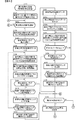
次に、演出制御基板12の動作を説明する。先ず、演出制御用CPU120は、電源が投入されると、図5に示すメイン処理の実行を開始する。メイン処理では、まず、RAM領域のクリアや各種初期値の設定、また演出制御の起動間隔(例えば、2ms)を決めるためのタイマの初期設定等を行うための第1初期化処理(S50)と、各可動体(第1演出装置300の枠側演出体301B,301Cや盤側演出体311B,311C、第2演出装置400の可動体401及び第3演出装置500の可動体501)の原点位置への復帰と動作確認を行うための第2初期化処理を行う(S51)。
Next, the operation of the
その後、演出制御用CPU120は、タイマ割込フラグの監視(S52)を行うループ処理に移行する。タイマ割込が発生すると、演出制御用CPU120は、タイマ割込処理によりタイマ割込フラグをセットする。メイン処理で、タイマ割込フラグがセット(オン)されていたら、演出制御用CPU120は、そのフラグをクリアし(S53)、以下の処理を実行する。
Thereafter, the
演出制御用CPU120は、まず、コマンド解析処理を行う(S54)。コマンド解析処理では、受信コマンドバッファに格納されている主基板11から送信されてきたコマンドが、どのコマンド(図5参照)であるのか解析する。尚、遊技制御用マイクロコンピュータ100から送信された演出制御コマンドは、演出制御INT信号にもとづく割込処理で受信され、RAMに形成されているバッファ領域に保存されている。そして、受信した演出制御コマンドに応じたフラグをセットする処理等を行う。
The
次いで、演出制御用CPU120は、演出制御プロセス処理を行う(S55)。演出制御プロセス処理では、制御状態に応じた各プロセスのうち、現在の制御状態(演出制御プロセスフラグ)に対応した処理を選択して演出表示装置5の表示制御を実行する。
Next, the
次いで、大当り図柄判定用乱数などの演出用乱数を生成するためのカウンタのカウント値を更新する演出用乱数更新処理を実行した後(S56)、サブ側エラー処理(S57)を実行し、その後、S52に移行する。 Next, after performing the effect random number update process for updating the counter value for generating the effect random number such as the jackpot symbol determination random number (S56), the sub-side error process (S57) is performed, The process proceeds to S52.
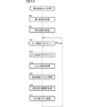
図6は、本実施例の第2初期化処理(S51)を示すフローチャートである。第2初期化処理において演出制御用CPU120は、先ず、設定データに基づいて最初に動作させる可動体を特定する(S101)。設定データには、可動体の順序データが含まれており、本実施例では、該順序として第1演出装置300→第2演出装置400→第3演出装置500の順が予め設定されている。第1演出装置300は、複数の可動体(枠側演出体301B,301C及び盤側演出体311B,311C)を有していることから、枠側演出体301B→枠側演出体301C→盤側演出体311B→盤側演出体311C→可動体401→可動体501の順が予め設定されている。よって、最初にS101が実行されるときには、第1演出装置300の枠側演出体301Bが対象の可動体として特定されることになる。尚、動作順序は任意であり、種々に変更可能である。
FIG. 6 is a flowchart showing the second initialization process (S51) of this embodiment. In the second initialization process, the
次いで、S101で特定した可動体が原点検出を行うことが必要な原点検出対象可動体であるか否かを判定する(S102)。 Next, it is determined whether or not the movable body specified in S101 is an origin detection target movable body that requires origin detection (S102).
本実施例において、これら原点検出を行うことが必要な原点検出対象可動体としては、枠側演出体位置センサ330A〜330E及び盤側演出体位置センサ340A〜340Eを有する第1演出装置300と、第2可動体用位置センサ420を有する第2演出装置400と、を有し、原点検出センサを有しない第3演出装置500の可動体501は該当しない。よって、S101で特定した可動体が第1演出装置300の枠側演出体301B,301C、盤側演出体311B,311C、第2演出装置400の可動体401のいずれかである場合には、該判定において「Y」と判定される一方、S101で特定した可動体が第3演出装置500である場合には、「N」と判定されることになる。
In the present embodiment, as the origin detection target movable body that needs to perform the origin detection, the
S102において「N」と判定された場合にはS130に進む。一方、S102において「Y」と判定された場合には、S103に進んで、動作対象可動体に対応する原点検出センサの検出状態を特定し(S103)、原点検出センサが検出状態であるか否か、つまり、対象の可動体が原点位置(初期位置)に位置しているか否かを判定する(S104)。 When it is determined “N” in S102, the process proceeds to S130. On the other hand, if “Y” is determined in S102, the process proceeds to S103, the detection state of the origin detection sensor corresponding to the movable body to be operated is specified (S103), and whether the origin detection sensor is in the detection state or not. That is, it is determined whether or not the target movable body is located at the origin position (initial position) (S104).
原点位置(初期位置)に位置していない場合(S104;N)には、S105に進んで、非検出時動作制御の実行回数を計数するための非検出時動作回数カウンタに0をセットした後(S105)、動作対象可動体を動作させるための制御速度として、後述する実動作確認用動作制御(ロング初期化動作制御)における最低速度(図8、図9参照)と同じ動作速度で動作対象可動体を動作させるための最低制御速度を設定し(S106)、動作対象可動体の駆動モータ、例えば、動作対象可動体が第1演出装置300であれば、枠側演出体用モータ310A,310B及び盤側演出体用モータ320A,320Bを原点位置方向に駆動開始し、例えば、動作対象可動体が第2演出装置400であれば、第2可動体用モータ410を原点位置方向に駆動開始するとともに(S107)、非検出時動作期間タイマのタイマカウントを開始する(S108)。尚、非検出時動作期間タイマのタイマカウントは、例えば、第1初期化処理にて初期化されたCTCから一定期間毎に出力される信号の数をカウントすること等により行うようにすればよい。
If it is not at the origin position (initial position) (S104; N), the process proceeds to S105, and after setting the non-detection operation count counter to 0 to count the number of executions of non-detection operation control (S105) As a control speed for operating the operation target movable body, the operation target is the same operation speed as the minimum speed (see FIGS. 8 and 9) in the actual operation confirmation operation control (long initialization operation control) described later. A minimum control speed for operating the movable body is set (S106), and if the operation target movable body is the
そして、原点検出センサが検出状態となるかとともに、非検出時動作期間タイマが上限時間に対応する値となったか否かを監視する監視状態に移行する(S109、S110)。 Then, a transition is made to a monitoring state in which the origin detection sensor enters a detection state and monitors whether or not the non-detection operation period timer has reached a value corresponding to the upper limit time (S109, S110).
動作対象可動体の駆動装置(例えば、枠側演出体用モータ310A,310B及び盤側演出体用モータ320A,320B等)を原点位置方向に駆動させることで動作対象可動体が原点位置(初期位置)に位置して原点検出センサが検出状態となった場合には、駆動モータの駆動を停止してS130に進む。一方、非検出時動作期間タイマが上限時間に対応する値となった場合、つまり、上限時間が経過しても動作対象可動体が原点位置(初期位置)に位置しなかった場合には、S112に進んで、非検出時動作回数カウンタに1を加算して(S112)、該加算後の非検出時動作回数カウンタの値が、動作エラー判定回数(例えば3)に達したか否かを判定する(S113)。
The operation target movable body is moved to the origin position (initial position) by driving the drive apparatus for the operation target movable body (for example, the frame
S113において非検出時動作回数カウンタの値が動作エラー判定回数に達している場合には、駆動モータの駆動を停止し、当該動作対象可動体の動作エラー(原点復帰エラー)を記憶し(S114)、S130に進む。つまり、非検出時動作制御において動作対象可動体が原点位置(初期位置)に位置しなかった場合には、当該動作対象可動体について後述する実動作確認用動作制御を実行しないようにする(当該動作対象可動体をデッドエンド状態する)ために動作エラーを記憶し、S130に進む。 If the value of the non-detection operation number counter reaches the number of operation error determinations in S113, the drive motor is stopped and the operation error (origin return error) of the operation target movable body is stored (S114). The process proceeds to S130. That is, when the operation target movable body is not located at the origin position (initial position) in the non-detection operation control, the operation control for actual operation confirmation described later is not executed for the operation target movable body ( The operation error is stored in order to set the operation target movable body to the dead end state, and the process proceeds to S130.
尚、本実施例では、S113において非検出時動作回数カウンタの値が動作エラー判定回数に達している場合には、当該動作対象可動体をデッドエンド状態する形態を例示したが、本発明はこれに限定されるものではなく、S113において非検出時動作回数カウンタの値が動作エラー判定回数に達している場合に、初期化エラー処理を開始し、該初期化エラー処理を実行することにより、第2初期化処理を中断することで、演出制御メイン処理がS52に進むことなく中断され、演出制御基板12(演出制御用CPU120など)は起動しない状態(デットエンド状態)にするようにしてもよい。
In this embodiment, when the value of the non-detection operation frequency counter reaches the operation error determination number in S113, the operation target movable body is illustrated as being in a dead end state. When the value of the non-detection operation number counter reaches the operation error determination number in S113, the initialization error process is started, and the initialization error process is executed, whereby 2 By interrupting the initialization process, the effect control main process may be interrupted without proceeding to S52, and the effect control board 12 (
また、動作対象可動体をデッドエンド状態とした場合、演出制御基板12(演出制御用CPU120など)は起動するが、例えば、演出制御用CPU120は、可動体を動作させることを示す入力信号(例えば、演出ボタン等の検出信号)の受付けを無効としたり、該入力信号が入力されても、当該動作対象可動体を動作させないようにするといった処理を実行することが好ましい。
When the operation target movable body is set to the dead end state, the effect control board 12 (the
一方、非検出時動作回数カウンタの値が動作エラー判定回数に達していない場合には、駆動モータの駆動を停止してS106に戻り、再度、S106〜S108の処理を行うことにより、動作対象可動体を、実動作確認用動作制御(ロング初期化動作制御)における最低速度にて原点位置に移動させる動作(非検出時動作制御)を開始して、前述したS109、S110の監視状態に移行する。 On the other hand, if the value of the non-detection operation number counter has not reached the number of operation error determinations, the drive motor is stopped, the process returns to S106, and the processes of S106 to S108 are performed again to move the operation target. The operation of moving the body to the origin position at the lowest speed in the actual operation confirmation operation control (long initialization operation control) (non-detection operation control) is started, and the monitoring state of S109 and S110 described above is entered. .
よって、S110にてエラー判定時間が経過したと判定されたとしても、動作エラー判定回数に達するまで繰返し動作対象可動体を原点位置(初期位置)に移動させる動作(非検出時動作制御)を実行している間に動作対象可動体が原点位置(初期位置)にて検出した場合には、S114に進むことなく、S130に進むことになる。 Therefore, even if it is determined in S110 that the error determination time has elapsed, the operation (moving control at the time of non-detection) is performed to repeatedly move the movable object to be moved to the origin position (initial position) until the operation error determination count is reached. If the operation target movable body is detected at the origin position (initial position) during the operation, the process proceeds to S130 without proceeding to S114.
一方、上記したS104において「Y」と判定されてS120に進んだ場合には、検出時動作回数カウンタに0をセットした後、検出時動作プロセスデータをセットし(S121a)、検出時動作プロセスタイマのタイマカウントを開始する(S121b)。尚、検出時動作プロセスタイマのタイマカウントとしては、前述した非検出時動作期間タイマのタイマカウントと同様に、第1初期化処理にて初期化されたCTCから一定期間毎に出力される信号の数をカウントすること等により行うようにすればよい。また、本実施例の検出時動作プロセスデータには、動作対象可動体を動作させるための制御速度として、後述する実動作確認用動作制御(ロング初期化動作制御)における最低速度(図8、図9参照)と同じ動作速度で動作対象可動体を動作させるための最低制御速度が記述(設定)されている。 On the other hand, if “Y” is determined in S104 and the process proceeds to S120, 0 is set in the operation count counter at detection, and then the operation process data at detection is set (S121a). The timer count is started (S121b). As the timer count of the detection process timer, the signal output at regular intervals from the CTC initialized in the first initialization process is the same as the timer count of the non-detection operation period timer described above. This may be done by counting the number or the like. Further, in the detection operation process data of the present embodiment, as a control speed for operating the movable object to be operated, a minimum speed (actual operation check operation control (long initialization operation control) described later (FIG. 8, FIG. 8) 9), the minimum control speed for operating the movable object to be operated is described (set).
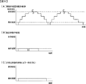
次いで、セットされた検出時動作プロセスデータに設定されている最低制御速度に基づいて動作対象可動体を動作させるとともに(S122)、プロセスデータが完了したか否かを判定し(S123)、プロセスデータが完了していない場合には、S122に戻り、動作対象可動体を検出時動作プロセスデータに設定されている最低制御速度に基づいて動作させる。 Next, the operation target movable body is operated based on the minimum control speed set in the set detection-time operation process data (S122), and it is determined whether or not the process data is completed (S123). If not completed, the process returns to S122, and the operation target movable body is operated based on the minimum control speed set in the operation process data at the time of detection.
このように、検出時動作制御においては、検出時動作プロセスデータが完了するまで、検出時動作プロセスデータに設定されている最低制御速度に基づく最低速度、つまり、実動作確認用動作制御(ロング初期化動作制御)における最低速度にて、原点位置(初期位置)から一旦離れ、該原点位置(初期位置)から離れた位置から原点位置(初期位置)に戻るという動作を行う(図8参照)。尚、原点位置から離れた位置とは、原点位置の近傍位置、つまり、各原点センサにより各可動体の被検出部を検出できない位置であって各演出位置よりも原点位置に近い所定位置(検出時動作位置)として設定されている。 In this way, in the detection operation control, until the detection operation process data is completed, the minimum speed based on the minimum control speed set in the detection operation process data, that is, the actual operation confirmation operation control (long initial At the lowest speed in the control operation), an operation of once leaving the origin position (initial position) and returning from the position away from the origin position (initial position) to the origin position (initial position) is performed (see FIG. 8). The position away from the origin position is a position in the vicinity of the origin position, that is, a position where the detected part of each movable body cannot be detected by each origin sensor, and is a predetermined position (detection) closer to the origin position than each effect position. Hour operating position).
S123の判定において、セットされている検出時動作プロセスデータが完了したと判定した場合には、可動役物駆動モータの駆動を停止してS124に進んで、原点検出センサが検出状態になっているか否か、つまり、動作対象可動体が原点位置(初期位置)に位置しているか否かを判定(確認)する。 If it is determined in S123 that the set operation process data at the time of detection is completed, the driving of the movable accessory drive motor is stopped and the process proceeds to S124, and the origin detection sensor is in the detection state. It is determined (confirmed) whether or not the operation target movable body is located at the origin position (initial position).
原点検出センサが検出状態になっている場合、つまり、動作対象可動体が原点位置(初期位置)に位置している場合にはS130に進む。 If the origin detection sensor is in the detection state, that is, if the operation target movable body is located at the origin position (initial position), the process proceeds to S130.
一方、原点検出センサが検出状態になっていない場合、つまり、動作対象可動体が原点位置(初期位置)に位置していない場合には、検出時動作回数カウンタに1を加算して(S126)、該加算後の検出時動作回数カウンタの値が、動作エラー判定回数(例えば3)に達したか否かを判定する(S127)。検出時動作回数カウンタの値が動作エラー判定回数に達している場合には、S128に進んで当該動作対象可動体の動作エラーを記憶し(S128)、S130に進む。つまり、検出時動作制御において動作対象可動体が原点位置(初期位置)に位置しなかった場合には、当該動作対象可動体について後述する実動作確認用動作制御を実行しないようにする(当該動作対象可動体をデッドエンド状態する)ために動作エラーを記憶し、S130に進む。 On the other hand, when the origin detection sensor is not in the detection state, that is, when the operation target movable body is not located at the origin position (initial position), 1 is added to the operation count counter during detection (S126). Then, it is determined whether or not the value of the detection-time operation number counter after the addition has reached the operation error determination number (for example, 3) (S127). When the value of the operation number counter at the time of detection reaches the number of operation error determinations, the process proceeds to S128 to store the operation error of the movable object to be operated (S128), and the process proceeds to S130. That is, when the operation target movable body is not located at the origin position (initial position) in the operation control at the time of detection, the operation control for actual operation confirmation to be described later is not executed for the operation target movable body (the operation concerned) The operation error is stored in order to set the target movable body to the dead end state, and the process proceeds to S130.
尚、本実施例では、S127において検出時動作回数カウンタの値が動作エラー判定回数に達している場合には、当該動作対象可動体をデッドエンド状態する形態を例示したが、本発明はこれに限定されるものではなく、S113において検出時動作回数カウンタの値が動作エラー判定回数に達している場合に、初期化エラー処理を開始し、該初期化エラー処理を実行することにより、第2初期化処理が中断されることで、演出制御メイン処理がS52に進むことなく中断され、演出制御基板12は起動しない状態(デットエンド状態)にするようにしてもよい。
In the present embodiment, the mode in which the operation target movable body is set to the dead end state when the value of the operation count counter at the time of detection reaches the number of operation error determinations in S127 is exemplified. Without being limited thereto, when the value of the detection operation number counter reaches the number of operation error determinations in S113, the initialization error process is started, and the initialization error process is executed, whereby the second initial The production control main process may be interrupted without proceeding to S52 and the
また、動作対象可動体をデッドエンド状態とした場合、演出制御基板12(演出制御用CPU120など)は起動するが、例えば、演出制御用CPU120は、可動体を動作させる入力信号(例えば、演出ボタン等の検出信号)の受付けを無効としたり、該入力信号が入力されても当該動作対象可動体を動作させないようにするといった処理を実行することが好ましい。
Also, when the operation target movable body is set to the dead end state, the effect control board 12 (the
S102で「N]と判定された場合、S109で「Y」と判定された場合、もしくはS124で「Y」と判定された場合に実行するS130においては、可動体のうちで未だ動作対象としていない残りの可動体が存在するか否かを判定し、残りの可動体が存在しない場合(具体的には、動作対象可動体が第3演出装置500である場合)には、図7に示す実動作確認用動作制御を行う処理に移行する。一方、残りの可動体が存在する場合には、S131に進んで、次に動作させる可動体を特定した後、S102に戻って、該特定した動作対象可動体について、S102以降の上記した処理を同様に実行する。 In S130, which is executed when “N” is determined in S102, “Y” is determined in S109, or “Y” is determined in S124, the movable body is not yet an operation target. It is determined whether or not there is a remaining movable body, and when there is no remaining movable body (specifically, when the operation target movable body is the third effect device 500), the actual operation shown in FIG. The processing shifts to processing for performing operation control for operation confirmation. On the other hand, if there are remaining movable bodies, the process proceeds to S131, the movable body to be operated next is specified, then the process returns to S102, and the above-described processing from S102 is performed on the identified movable object. Do the same.
尚、動作対象可動体が第1演出装置300の枠側演出体301Bである場合にS131が実行される場合には、設定データに基づいて第1演出装置300の枠側演出体301Cが動作対象可動体として特定され、動作対象可動体が第1演出装置300の枠側演出体301Cである場合にS131が実行される場合には、第1演出装置300の盤側演出体311Bが動作対象可動体として特定され、動作対象可動体が第1演出装置300の盤側演出体311Bである場合にS131が実行される場合には、設定データに基づいて第1演出装置300の盤側演出体311Cが動作対象可動体として特定され、動作対象可動体が第1演出装置300の盤側演出体311Cである場合にS131が実行される場合には、設定データに基づいて第2演出装置400の可動体401が動作対象可動体として特定され、動作対象可動体が第2演出装置400の可動体401である場合にS131が実行される場合には、第3演出装置500の可動体501が動作対象可動体として特定される。
In addition, when S131 is performed when the operation target movable body is the frame
次に図7に示す処理について説明すると、図7に示すS200において演出制御用CPU120は、先ず、前述のS101と同様に、設定データに基づいて最初に動作確認する可動体(確認対象可動体)を特定する(S200)。次いで、当該対象可動体の動作エラーの記憶が有るか否かを判定する(S201)。
Next, the processing shown in FIG. 7 will be described. First, in S200 shown in FIG. 7, the
確認対象可動体の動作エラーの記憶が有る場合は、S202a〜S213までの処理を実行することなくS220に進む。このようにすることで、本実施例では、これら非検出時動作制御や検出時動作制御において動作エラーと判定された可動体については実動作確認用動作制御を行わないようになっている。 If there is a storage of the operation error of the movable body to be confirmed, the process proceeds to S220 without executing the processes from S202a to S213. In this way, in this embodiment, the operation control for actual operation confirmation is not performed for the movable body that is determined to be an operation error in the non-detection operation control or the detection operation control.
一方、確認対象可動体の動作エラーの記憶が無い場合は、S202aに進んで、確認対象可動体に対応する実動作確認用プロセスデータをセットする。つまり、確認対象可動体が第1演出装置300(枠側演出体301B,301C及び盤側演出体311B,311C)であれば、第1演出装置300の実動作確認用プロセスデータをセットし、確認対象可動体が第2演出装置400(可動体401)であれば、第2演出装置400の実動作確認用プロセスデータをセットし、確認対象可動体が第3演出装置500(可動体501)であれば、第3演出装置500の実動作確認用プロセスデータをセットする。尚、これら各実動作確認用プロセスデータには、演出において当該可動体が可動体演出において実際に行う動作と同一の動作を行うように制御速度等が記述(設定)されている。
On the other hand, when there is no memory of the operation error of the confirmation target movable body, the process proceeds to S202a, where process data for actual operation confirmation corresponding to the confirmation target movable body is set. That is, if the confirmation target movable body is the first effect device 300 (the frame-
次いで、実動作確認用プロセスタイマのタイマカウントを開始する(S202b)。尚、実動作確認用プロセスタイマのタイマカウントとしては、前述した非検出時動作期間タイマのタイマカウントと同様に、第1初期化処理にて初期化されたCTCから一定期間毎に出力される信号の数をカウントすること等により行うようにすればよい。 Next, the timer count of the process timer for actual operation confirmation is started (S202b). Note that the timer count of the process timer for actual operation confirmation is a signal output at regular intervals from the CTC initialized in the first initialization process, like the timer count of the non-detection operation period timer described above. This may be done by counting the number of
そして、セットされた実動作確認用プロセスデータにおいて実動作確認用プロセスタイマのタイマカウント値に対応して設定されている制御速度にて確認対象可動体を動作させるとともに(S203)、プロセスデータが完了したか否かを判定し(S204)、プロセスデータが完了していない場合には、S203に戻り、確認対象可動体を、その時点の実動作確認用プロセスタイマのタイマカウント値に対応して設定されている制御速度に基づいて動作させる。 Then, the movable object to be confirmed is operated at the control speed set corresponding to the timer count value of the actual operation confirmation process timer in the set actual operation confirmation process data (S203), and the process data is completed. (S204) If the process data is not completed, the process returns to S203, and the confirmation object movable body is set corresponding to the timer count value of the actual operation confirmation process timer at that time. Operate based on the controlled speed.
このように、実動作確認用プロセスデータが完了するまで、実動作確認用プロセスデータに実動作確認用プロセスタイマのタイマカウント値に対応して設定されている制御速度にて確認対象可動体を動作させることにより、確認対象可動体の制御速度を、時系列的に順次変更して、可動体演出において当該可動体を実際に動作させる際に設定する制御速度と同一の加速または減速を行うことができる。 As described above, until the actual operation check process data is completed, the confirmation target movable body is operated at the control speed set in the actual operation check process data corresponding to the timer count value of the actual operation check process timer. By doing so, the control speed of the movable body to be confirmed can be sequentially changed in time series, and the same acceleration or deceleration as the control speed set when the movable body is actually operated in the movable body effect can be performed. it can.
そして、S204の判定において、セットされている実動作確認用プロセスデータが完了したと判定した場合には、駆動モータの駆動を停止し、当該確認対象可動体は原点検出対象可動体であるか否かを判定する(S204a)。当該確認対象可動体が原点検出対象可動体でなければ、つまり、第3演出装置500であればS220に進む。一方、当該対象役物が原点検出対象可動体であれば、つまり、第1演出装置300または第2演出装置400であれば原点検出センサが検出状態になっているか否か、つまり、動作対象可動体が原点位置(初期位置)に位置しているか否かを判定(確認)する(S205)。
If it is determined in step S204 that the set process data for actual operation confirmation has been completed, the drive motor is stopped, and whether or not the confirmation target movable body is an origin detection target movable body. Is determined (S204a). If the confirmation target movable body is not the origin detection target movable body, that is, if it is the
原点検出センサが検出状態になっている場合、つまり、確認対象可動体が原点位置(初期位置)に位置している場合にはS220に進む。一方、原点検出センサが検出状態になっていない場合、つまり、確認対象可動体が原点位置(初期位置)に位置していない場合には、前述した非検出時動作制御を(図6参照)を行って確認対象可動体を原点位置(初期位置)に位置させるためにS206〜S213の処理を行う。 When the origin detection sensor is in the detection state, that is, when the confirmation target movable body is located at the origin position (initial position), the process proceeds to S220. On the other hand, when the origin detection sensor is not in the detection state, that is, when the confirmation target movable body is not located at the origin position (initial position), the above-described non-detection operation control is performed (see FIG. 6). Steps S206 to S213 are performed in order to position the movable body to be confirmed at the origin position (initial position).
具体的には、非検出時動作制御の実行回数を計数するための非検出時動作回数カウンタに0をセットした後(S206)、制御速度として実動作確認用動作制御(ロング初期化動作制御)における最低速度と同じ動作速度で動作対象可動体を動作させるための最低制御速度を設定し(S207)、確認対象可動体の駆動装置、例えば、確認対象可動体が第1演出装置300であれば、枠側演出体用モータ310A,310B、盤側演出体用モータ320A,320Bを原点位置(初期位置)方向に駆動開始するとともに(S208)、非検出時動作期間タイマのタイマカウントを開始する(S209)。
Specifically, after setting 0 to the non-detection operation frequency counter for counting the number of executions of non-detection operation control (S206), the actual operation check operation control (long initialization operation control) is set as the control speed. The minimum control speed for operating the operation target movable body at the same operation speed as the minimum speed is set (S207), and the confirmation target movable body drive device, for example, if the confirmation target movable body is the
そして、原点検出センサが検出状態となるかとともに、非検出時動作期間タイマが上限時間に対応する値となったか否かを監視する監視状態に移行する(S210、S211)。 Then, a transition is made to a monitoring state for monitoring whether the origin detection sensor is in a detection state and whether the non-detection operation period timer has a value corresponding to the upper limit time (S210, S211).
確認対象可動体の駆動装置(例えば、枠側演出体用モータ310A,310B、盤側演出体用モータ320A,320B)を原点位置(初期位置)方向に駆動させることで確認対象可動体が原点位置(初期位置)に位置して原点検出センサが検出状態となった場合には、S210にて「Y」と判定されてS220に進む。一方、非検出時動作期間タイマが上限時間に対応する値となった場合、つまり、上限時間が経過しても確認対象可動体が原点位置(初期位置)に位置しなかった場合には、S212に進んで、非検出時動作回数カウンタに1を加算して(S212)、該加算後の非検出時動作回数カウンタの値が、動作エラー判定回数(例えば3)に達したか否かを判定する(S213)。
The confirmation target movable body is moved to the origin position by driving the confirmation target movable body drive device (for example, the frame side
非検出時動作回数カウンタの値が動作エラー判定回数に達している場合には、当該動作対象可動体の動作エラーを記憶して(S214)、当該動作対象可動体について以後は実動作を実行しないようにするようにし、S220に進む。尚、本実施例では、S213において非検出時動作回数カウンタの値が動作エラー判定回数に達している場合に、当該動作対象可動体の動作エラーを記憶し、当該動作対象可動体について以後は実動作を実行しないようにするようにしたが、本発明はこれに限定されるものではなく、S213において非検出時動作回数カウンタの値が動作エラー判定回数に達している場合には、当該動作対象可動体をデッドエンド状態にするようにしてもよい。あるいは、初期化エラー処理を開始し、該初期化エラー処理を実行することにより、第2初期化処理が中断されることで、演出制御メイン処理がS52に進むことなく中断され、演出制御基板12は起動しない状態(デットエンド状態)にするようにしてもよい。
When the value of the non-detection operation number counter reaches the number of operation error determinations, the operation error of the operation target movable body is stored (S214), and the actual operation is not executed thereafter for the operation target movable body. And proceed to S220. In this embodiment, when the value of the non-detection operation number counter reaches the number of operation error determinations in S213, the operation error of the operation target movable body is stored, and the operation target movable body is actually executed thereafter. The operation is not executed, but the present invention is not limited to this. When the value of the non-detection operation number counter reaches the operation error determination number in S213, the operation target The movable body may be in a dead end state. Alternatively, by starting the initialization error process and executing the initialization error process, the second initialization process is interrupted, whereby the effect control main process is interrupted without proceeding to S52, and the
また、動作対象可動体をデッドエンド状態とした場合、演出制御基板12(演出制御用CPU120など)は起動するが、例えば、演出制御用CPU120は、可動体を動作させる入力信号(例えば、演出ボタン等の検出信号)の受付けを無効としたり、該入力信号が入力されても当該動作対象可動体を動作させないようにするといった処理を実行することが好ましい。
Also, when the operation target movable body is set to the dead end state, the effect control board 12 (the
一方、非検出時動作回数カウンタの値が動作エラー判定回数に達していない場合には、S207に戻り、再度、S207、S208、S209の処理を行うことにより、確認対象可動体を、実動作確認用動作制御(ロング初期化動作制御)における最低速度にて原点位置(初期位置)に移動させる動作(原点復帰時動作)を開始して、前述したS210、S211の監視状態に移行する。 On the other hand, when the value of the non-detection operation number counter has not reached the operation error determination number, the process returns to S207, and the processing of S207, S208, and S209 is performed again, and the movable body to be confirmed is confirmed as the actual operation The operation to move to the origin position (initial position) at the lowest speed in the operation control (long initialization operation control) (the operation at the time of returning to the origin) is started, and the process proceeds to the monitoring state of S210 and S211 described above.
よって、S211にてエラー判定時間が経過したと判定されたとしても、動作エラー判定回数に達するまで繰返し確認対象可動体を原点位置(初期位置)に移動させる動作(非検出時動作制御)を実行している間において、確認対象可動体が原点位置(初期位置)にて検出された場合には、S220に進むことになる。 Therefore, even if it is determined in S211 that the error determination time has elapsed, an operation (non-detection operation control) of moving the movable object to be repeatedly checked to the origin position (initial position) is performed until the operation error determination count is reached. If the confirmation target movable body is detected at the origin position (initial position) during the operation, the process proceeds to S220.
S201で「Y」と判定された場合、S204aで「N」と判定された場合、S205で「Y」と判定された場合、もしくはS210で「Y」と判定された場合に実行するS220においては、可動体のうちで未だ動作確認の確認対象としていない残りの可動体が存在するか否かを判定し、残りの可動体が存在しない場合(具体的には、動作確認の対象役物が第3演出装置500である場合)には、当該処理を終了する一方、残りの可動体が存在する場合には、S221に進んで、次に動作確認する可動体を特定した後、S201に戻って、該特定した対象体について、S201以降の上記した処理を同様に実行する。尚、S220において残りの可動体が存在しない場合に動作エラー記録が記憶されている場合、次回の電源投入時に第2初期化処理が実行されることで解消した場合、その時点でクリアされることになる。 In S220 executed when “Y” is determined in S201, “N” is determined in S204a, “Y” is determined in S205, or “Y” is determined in S210. , It is determined whether or not there are any remaining movable bodies that have not yet been confirmed for operation confirmation, and if there are no remaining movable bodies (specifically, In the case of the 3 effect device 500), the process ends. On the other hand, if there are remaining movable bodies, the process proceeds to S221, the movable body to be checked next is specified, and the process returns to S201. The above-described processing from S201 onward is similarly executed for the identified target object. Note that if an operation error record is stored when there is no remaining movable body in S220, it is cleared when the second initialization process is executed when the power is turned on next time. become.
ここで、これら図6、図7に示す第2初期化処理が実行されることによる可動体の動作態様及び制御内容について、図8、図9を用いて説明する。図8は、演出制御用CPU120が行う非検出時動作制御、検出時動作制御及び実動作確認用動作制御の動作態様を示す概略説明図である。図9は、(A)は実動作確認用動作制御における制御速度を示す説明図、(B)は検出時動作制御における制御速度を示す説明図、(C)は非検出時動作制御における制御速度を示す説明図である。
Here, the operation mode and control contents of the movable body by executing the second initialization process shown in FIGS. 6 and 7 will be described with reference to FIGS. FIG. 8 is a schematic explanatory diagram illustrating operation modes of the non-detection operation control, the detection operation control, and the actual operation confirmation operation control performed by the
尚、図8及び図9においては、原点検出対象可動体である第1演出装置300の枠側演出体301B,301Cや盤側演出体311B,311C及び第2演出装置400の可動体401における非検出時動作制御(ショート初期化動作制御)、検出時動作制御(ショート初期化動作制御)及び実動作確認用動作制御(ロング初期化動作制御)についてのみ説明し、原点検出対象可動体でない第3演出装置500の可動体501についての説明は省略することとする。また、第1演出装置300の枠側演出体301B,301Cや盤側演出体311B,311C各々の往復動作距離(回動範囲)と第2演出装置400の可動体401の往復動作距離(移動範囲)とは同一ではないが、説明の便宜上、同一の概念図を用いて説明することとする。
8 and 9, the frame-side effects bodies 301 </ b> B and 301 </ b> C and the board-side effects bodies 311 </ b> B and 311 </ b> C of the
図8に示すように、第1演出装置300の枠側演出体301B,301Cや盤側演出体311B,311C及び第2演出装置400の可動体401は、それぞれ原点位置(退避位置、初期位置)と演出位置(操作可能位置)との間で往復動作可能に設けられており、原点位置から演出位置への往動作や演出位置から原点位置への復動作は、前述した可動体演出等において実際に行う実動作とされている。
As shown in FIG. 8, the frame-
演出制御用CPU120は、第2初期化処理を実行したときに可動体の被検出部が原点検出センサにより検出されない場合、つまり、可動体が何らかの理由(例えば、搬送や遊技島への設置時に原点位置から動いてしまっている場合、前回の動作時に原点復帰できなかった場合(例えば、演出の実行時において、モータの脱調、故障、引っ掛かりなどにより可動体の原点復帰が確認できなかったり動作できなくなるといった可動体エラー(動作異常)が発生した場合など)、遊技機の振動により原点位置から動いてしまった場合など)により原点位置以外の位置(例えば、図8における非検出時動作制御に対応する黒丸で示す位置など、原点位置と演出位置との間の所定位置)にある場合、原点復帰させるための非検出時動作制御を実行する。この非検出時動作制御を実行する場合、可動体は原点位置から離れた位置にあるため、動作としては可動体を原点位置方向に移動させる動作のみとされている。
When the second initialization process is executed, the
また、演出制御用CPU120は、第2初期化処理を実行したときに第1演出装置300の枠側演出体301B,301Cや盤側演出体311B,311C及び第2演出装置400の可動体401の被検出部が原点検出センサにより検出された場合、検出時動作制御を実行する。
In addition, when the second initialization process is executed, the
例えば、被検出部が原点検出センサにより確実に検出されるように、被検出部が原点検出センサにより検出されたときから可動体の原点位置方向への動作が規制されるまでの間に所定の動作可能範囲(例えば、遊び)が設定されている場合などにおいては、原点復帰して原点検出センサにより検出された位置よりもさらに奥側にずれた位置に停止することがある。よって、被検出部が原点検出センサにより検出されていても、可動体をより正確な原点位置に復帰させるための検出時動作制御を行う。 For example, in order to ensure that the detected part is detected by the origin detection sensor, a predetermined period between the time when the detected part is detected by the origin detection sensor and the operation of the movable body in the direction of the origin position is restricted. When an operable range (for example, play) is set, the origin may return and stop at a position shifted further to the back than the position detected by the origin detection sensor. Therefore, even when the detected portion is detected by the origin detection sensor, the operation control during detection for returning the movable body to the more accurate origin position is performed.
この検出時動作制御は、原点検出センサによる被検出部の検出状態を一旦解除するために可動体を原点位置から離れた位置へ移動させた後に原点位置に復帰させる必要があるが、演出位置まで移動させる必要はないので、可動体を原点位置から該原点位置の近傍である検出時動作位置まで移動させた後、原点位置に復帰させる。つまり、実動作よりも短い距離で往復動作させる(図12(A)(B)参照)。 In this detection operation control, it is necessary to move the movable body to a position away from the origin position and then return it to the origin position in order to temporarily cancel the detection state of the detected part by the origin detection sensor. Since there is no need to move the movable body, the movable body is moved from the origin position to the detection-time operation position in the vicinity of the origin position, and then returned to the origin position. That is, the reciprocating operation is performed at a shorter distance than the actual operation (see FIGS. 12A and 12B).
また、演出制御用CPU120は、第2初期化処理において非検出時動作制御または検出時動作制御を実行した後、実動作確認用動作制御を実行する。実動作確認用動作制御は、可動体が各種演出等において実際に行う実動作と同一の動作とされている。尚、本実施例では、実動作確認用動作制御(ロング初期化動作制御)は、後述する可動演出パターンCのときの動作を行う。また、実動作確認用動作制御では、第1演出装置300の枠側演出体301B,301Cや盤側演出体311B,311C及び第2演出装置400の可動体401の各動作を確認するものであり、枠側演出体301B,301Cや盤側演出体311B,311C及び可動体401の連動はしない。
Further, the
次に、演出制御用CPU120が非検出時動作制御、検出時動作制御及び実動作確認用動作制御を実行する際に設定する制御速度について比較する。尚、図9(A)、図9(B)、図9(C)にて示す速度は、演出制御用CPU120が各可動体を動作させるために設定する制御速度であって、可動体の実際の動作速度とは異なる。つまり、例えば、所定の可動体を動作させる場合において、原点位置と演出位置との間における一の移動区間と他の移動区間に同一の制御速度を設定した場合でも、一の移動区間と他の移動区間とで態様が異なる場合(例えば、バネがある区間とない区間、直線区間と曲線区間)や、同一の移動区間でも上昇する場合と下降する場合においては、可動体を実際に動作させた場合の動作速度は制御速度とは異なることがある。また、可動体に対し同一の制御速度を設定しても、各可動体の大きさ、重量、動作態様、動作距離、駆動機構等の違いがある場合、各可動体の実際の動作速度は必ずしも同一にはならない。複数の可動体を同一性能のステッピングモータにて動作させる場合において、各可動体に対し同一の制御速度を設定しても、各可動体の大きさ、重量、動作態様、動作距離、駆動機構等の違いがある場合、各可動体の実際の動作速度は必ずしも同一にはならない。
Next, the control speeds set when the
図9(A)に示すように、演出制御用CPU120は、実動作確認用動作制御を実行する場合、セットした実動作確認用プロセスデータにおいて実動作確認用プロセスタイマのタイマカウント値に対応して設定されている制御速度に基づいて確認対象可動体を動作させる。具体的には、原点位置から加速した後に減速して演出位置に停止させるとともに、演出位置から加速した後に減速して原点位置に停止させる制御を行う。すなわち、各可動体が正常に動作可能であることを確認するための実動作確認用動作制御では、原点位置と演出位置との間において、可動体の制御速度を低速→高速→低速の順に変化させる。つまり、演出制御用CPU120は、各可動体の可動体演出を実行する場合、第1速度である最低速度(低速)と該最低速度よりも速い第2速度としての最高速度(高速)との範囲内の速度で各可動体が動作するように制御するため、実動作確認用動作制御を実行する場合においても、第1速度である最低速度(低速)と該最低速度よりも速い第2速度としての最高速度(高速)との範囲内の速度で各可動体が動作するように制御する。
As shown in FIG. 9A, when performing the actual operation confirmation operation control, the
すなわち、上記第1速度としての最低速度や第2速度としての最高速度は、可動体の実際の動作速度であって、該動作速度としての最低速度や最高速度となるように制御速度が設定されることになる。尚、以下においては、最低制御速度に基づいて可動体を動作させた場合は最低速度にて動作し、最高制御速度に基づいて可動体を動作させた場合は最高速度にて動作するものとして説明する。 That is, the minimum speed as the first speed and the maximum speed as the second speed are actual operating speeds of the movable body, and the control speed is set to be the minimum speed and the maximum speed as the operating speed. Will be. In the following description, it is assumed that when the movable body is operated based on the minimum control speed, it operates at the minimum speed, and when the movable body is operated based on the maximum control speed, it operates at the maximum speed. To do.
ここで、可動体の加速時及び減速時における動作速度が、実動作確認用動作制御における最低速度となるように制御速度が設定されている。また、演出位置に移動した後に原点位置に復帰させる際においては、演出位置に停止させるときよりも長い時間にわたり実動作確認用動作制御における最低速度となるように制御することで、可動体を確実に減速させてから原点検出センサにより被検出部が検出されるようにしている。 Here, the control speed is set so that the operation speed at the time of acceleration and deceleration of the movable body becomes the minimum speed in the operation control for actual operation confirmation. In addition, when returning to the origin position after moving to the production position, the movable body can be surely secured by controlling so that it becomes the minimum speed in the action control for actual operation confirmation over a longer time than when stopping at the production position. The detected portion is detected by the origin detection sensor after the vehicle is decelerated.
図9(B)に示すように、演出制御用CPU120は、検出時動作制御を実行する場合、原点位置から演出位置まで移動させる期間及び演出位置から原点位置まで移動させる期間において、常に実動作確認用動作制御における最低速度(第1速度)にて可動体が動作するように制御する。つまり、演出制御用CPU120は、第1動作制御としての検出時動作制御における最高速度が、第2動作制御としての実動作確認用動作制御における最低速度以下の速度(本実施例では、実動作確認用動作制御における最低速度と同じ速度)となるように、常に実動作確認用動作制御において設定されている制御速度のうち最も低い最低制御速度に基づいて可動体を動作させる制御を行う。
As shown in FIG. 9B, when performing the motion control at the time of detection, the
また、検出時動作制御の場合、実動作確認用動作制御に比べて可動体の動作距離が短いため、実動作確認用動作制御において加速したときの制御速度、つまり高速で動作させると、原点検出センサにて被検出部を確実に検出できなかったり、近距離から可動体が原点位置に復帰して移動規制されたときの衝撃により可動体等が破損したりする虞があるため、実動作確認用動作制御における最低速度にて動作するように制御する。 In the case of motion control during detection, the moving distance of the movable body is shorter than that for motion control for actual motion check. Check the actual operation because the sensor may not be able to detect the detected part reliably, or the movable body may be damaged due to impact when the movable body returns to the home position from a short distance and the movement is restricted. Control to operate at the lowest speed in operation control.
また、図9(C)に示すように、演出制御用CPU120は、非検出時動作制御を実行する場合、原点位置と演出位置との間の任意の位置から原点位置まで移動させる期間において、常に実動作確認用動作制御における最低速度(第1速度)にて動作するように制御する。つまり、演出制御用CPU120は、第1動作制御としての非検出時動作制御における最高速度(最大動作速度)が、第2動作制御としての実動作確認用動作制御における最低速度以下の速度(本実施例では、実動作確認用動作制御における最低速度と同じ速度)となるように、常に実動作確認用動作制御において設定されている制御速度のうち最も低い最低制御速度に基づいて可動体を動作させる制御を行う。
Further, as shown in FIG. 9C, when performing the non-detection operation control, the
この場合、可動体は原点位置からどの程度離れた位置にあるかが不明であるため、可動体が原点位置の近傍に位置していた場合、実動作確認用動作制御において加速したときの制御速度、つまり高速で動作させると、可動体が原点位置に復帰したときに原点検出センサにて被検出部を確実に検出できなかったり、近距離から可動体が原点位置に復帰して移動規制されたときの衝撃により可動体等が破損したりする虞があるため、実動作確認用動作制御における最低速度にて動作するように制御する。 In this case, since it is unknown how far the movable body is from the origin position, if the movable body is located near the origin position, the control speed when accelerating in the operation control for actual operation confirmation In other words, when operated at high speed, when the movable body returns to the origin position, the origin detection sensor cannot reliably detect the detected part, or the movable body returns to the origin position from a short distance and the movement is restricted. Since there is a possibility that the movable body or the like may be damaged due to an impact, control is performed so as to operate at the lowest speed in the operation control for actual operation confirmation.
このように本実施例では、演出制御用CPU120は、第1動作制御としての非検出時動作制御や検出時動作制御を実行する場合、実動作確認用動作制御において設定されている最低制御速度に基づいて常に単一(一定)の動作速度で可動体が動作するように制御を行う。そして、これら最低速度は、各可動体に対応する実動作確認用動作制御における最低速度であり、各可動体に共通する動作速度ではないので、各可動体における最低速度は異なる場合がある。
As described above, in the present embodiment, when performing the non-detection operation control or the detection operation control as the first operation control, the
具体的には、第1演出装置300の枠側演出体301B,301Cや盤側演出体311B,311C及び第2演出装置400の可動体401は、図1に示すように、大きさ、重量、動作態様、動作距離、駆動モータを含む駆動機構が各々異なるため、同一の制御速度を設定した場合でも可動体の実際の動作速度は異なる。また、各可動体に対し異なる制御速度を設定した場合においても可動体の実際の動作速度は異なる。このように、最低速度は各可動体に応じて設定された制御速度に基づく動作速度であり、可動体に最適な最低速度にて動作するように制御するため、態様が異なる複数の可動体を原点位置にて確実に検出させることが可能となる。
Specifically, the frame
図10は、演出制御メイン処理の演出制御プロセス処理(S55)を示すフローチャートである。演出制御プロセス処理では、演出制御用CPU120は、先ず、演出表示装置5の第1保留記憶表示エリア5D及び第2保留記憶表示エリア5Uでの保留記憶表示を、保留記憶バッファの記憶内容に応じた表示に更新する保留表示更新処理を実行する(S72)。
FIG. 10 is a flowchart showing the effect control process (S55) of the effect control main process. In the effect control process, the
その後、演出制御用CPU120は、演出制御プロセスフラグの値に応じてS73〜S79のうちのいずれかの処理を行う。各処理においては、以下のような処理を実行する。
Thereafter, the
変動パターン指定コマンド受信待ち処理(S73):遊技制御用マイクロコンピュータ100から変動パターン指定コマンドを受信しているか否か確認する。具体的には、コマンド解析処理で変動パターン指定コマンドを受信しているか否か確認する。変動パターン指定コマンドを受信していれば、演出制御プロセスフラグの値を演出図柄変動開始処理(S74)に対応した値に変更する。
Fluctuation pattern designation command reception waiting process (S73): It is confirmed whether or not a variation pattern designation command is received from the
演出図柄変動開始処理(S74):演出図柄の変動が開始されるように制御する。そして、演出制御プロセスフラグの値を演出図柄変動中処理(S75)に対応した値に更新する。 Effect symbol variation start processing (S74): Control is performed so that the variation of the effect symbol is started. Then, the value of the effect control process flag is updated to a value corresponding to the effect symbol changing process (S75).
演出図柄変動中処理(S75):変動パターンを構成する各変動状態(変動速度)の切替タイミングや、後述する可動演出において枠側演出体301A,301B,301C及び盤側演出体311A,311B,311Cの駆動やLEDの発光等を制御するとともに、変動時間の終了を監視する。そして、変動時間が終了したら、演出制御プロセスフラグの値を演出図柄変動停止処理(S76)に対応した値に更新する。
Production symbol variation processing (S75): The switching timing of each variation state (fluctuation speed) constituting the variation pattern and the frame-
演出図柄変動停止処理(S76):全図柄停止を指示する演出制御コマンド(図柄確定コマンド)を受信したことにもとづいて、演出図柄の変動を停止し表示結果(停止図柄)を導出表示する制御を行う。そして、演出制御プロセスフラグの値を大当り表示処理(S77)または変動パターン指定コマンド受信待ち処理(S73)に対応した値に更新する。 Effect symbol variation stop processing (S76): Based on the reception of the effect control command (symbol confirmation command) for instructing all symbols to stop, control is performed to stop the variation of the effect symbol and derive and display the display result (stop symbol). Do. Then, the value of the effect control process flag is updated to a value corresponding to the jackpot display process (S77) or the variation pattern designation command reception waiting process (S73).
大当り表示処理(S77):変動時間の終了後、演出表示装置5に大当りの発生を報知するための画面を表示する制御を行う。そして、演出制御プロセスフラグの値を大当り遊技中処理(S78)に対応した値に更新する。
Jackpot display process (S77): After the end of the variation time, control is performed to display a screen for notifying the
大当り遊技中処理(S78):大当り遊技中の制御を行う。例えば、大入賞口開放中指定コマンドや大入賞口開放後指定コマンドを受信したら、演出表示装置5におけるラウンド数の表示制御等を行う。そして、演出制御プロセスフラグの値を大当り終了演出処理(S79)に対応した値に更新する。
Big hit game processing (S78): Control during the big hit game is performed. For example, when receiving a special command during opening of the special prize opening or a designation command after opening the special prize opening, display control of the number of rounds in the
大当り終了演出処理(S79):演出表示装置5において、大当り遊技状態が終了したことを遊技者に報知する表示制御を行う。そして、演出制御プロセスフラグの値を変動パターン指定コマンド受信待ち処理(S73)に対応した値に更新する。
Big hit end effect process (S79): In the
図11は、図10に示された演出制御プロセス処理における演出図柄変動開始処理(S74)を示すフローチャートである。演出図柄変動開始処理において、演出制御用CPU120は、まず、S271において第1変動開始コマンド受信フラグがセットされているか否かを判定する(S271)。第1変動開始コマンド受信フラグがセットされている場合は(S271;Y)、始動入賞時受信コマンドバッファにおける第1特図保留記憶のバッファ番号「1−0」〜「1−4」に対応付けて格納されている各種コマンドデータと各種フラグを、バッファ番号1個分ずつ上位にシフトする(S272)。尚、バッファ番号「1−0」の内容については、シフトする先が存在しないためにシフトすることはできないので消去される。
FIG. 11 is a flowchart showing the effect symbol variation start process (S74) in the effect control process shown in FIG. In the effect symbol variation start process, the
具体的には、第1特図保留記憶のバッファ番号「1−1」に対応付けて格納されている各種コマンドデータと各種フラグをバッファ番号「1−0」に対応付けて格納するようにシフトし、第1特図保留記憶のバッファ番号「1−2」に対応付けて格納されている各種コマンドデータと各種フラグをバッファ番号「1−1」に対応付けて格納するようにシフトし、第1特図保留記憶のバッファ番号「1−3」に対応付けて格納されている各種コマンドデータと各種フラグをバッファ番号「1−2」に対応付けて格納するようにシフトし、第1特図保留記憶のバッファ番号「1−4」に対応付けて格納されている各種コマンドデータと各種フラグをバッファ番号「1−3」に対応付けて格納するようにシフトする。 Specifically, various command data and various flags stored in association with the buffer number “1-1” in the first special figure hold memory are shifted so as to be stored in association with the buffer number “1-0”. Then, the various command data and various flags stored in association with the buffer number “1-2” in the first special figure reservation memory are shifted so as to be stored in association with the buffer number “1-1”. Various command data and various flags stored in association with the buffer number “1-3” in the 1 special figure hold memory are shifted so as to be stored in association with the buffer number “1-2”. Various command data and various flags stored in association with the buffer number “1-4” in the pending storage are shifted so as to be stored in association with the buffer number “1-3”.
また、S271において第1変動開始コマンド受信フラグがセットされていない場合は(S271;N)、第2変動開始コマンド受信フラグがセットされているか否かを判定する(S273)。第2変動開始コマンド受信フラグがセットされていない場合は(S273;N)、演出図柄変動開始処理を終了し、第2変動開始コマンド受信フラグがセットされている場合は(S273;Y)、始動入賞時受信コマンドバッファにおける第2特図保留記憶のバッファ番号「2−0」〜「2−4」に対応付けて格納されている各種コマンドデータと各種フラグを、バッファ番号1個分ずつ上位にシフトする(S274)。尚、バッファ番号「2−0」の内容については、シフトする先が存在しないためにシフトすることはできないので消去される。 If the first variation start command reception flag is not set in S271 (S271; N), it is determined whether or not the second variation start command reception flag is set (S273). When the second variation start command reception flag is not set (S273; N), the effect symbol variation start process is terminated, and when the second variation start command reception flag is set (S273; Y), the start The various command data and various flags stored in association with the buffer numbers “2-0” to “2-4” of the second special figure hold memory in the received command buffer at the time of winning are placed higher by one buffer number. Shift (S274). Note that the contents of the buffer number “2-0” are erased because they cannot be shifted because there is no destination to shift.
具体的には、第2特図保留記憶のバッファ番号「2−1」に対応付けて格納されている各種コマンドデータと各種フラグをバッファ番号「2−0」に対応付けて格納するようにシフトし、第2特図保留記憶のバッファ番号「2−2」に対応付けて格納されている各種コマンドデータと各種フラグをバッファ番号「2−1」に対応付けて格納するようにシフトし、第2特図保留記憶のバッファ番号「2−3」に対応付けて格納されている各種コマンドデータと各種フラグをバッファ番号「2−2」に対応付けて格納するようにシフトし、第2特図保留記憶のバッファ番号「2−4」に対応付けて格納されている各種コマンドデータと各種フラグをバッファ番号「2−3」に対応付けて格納するようにシフトする。 Specifically, various command data and various flags stored in association with the buffer number “2-1” in the second special figure reservation memory are shifted so as to be stored in association with the buffer number “2-0”. Then, the various command data and the various flags stored in association with the buffer number “2-2” in the second special figure reservation memory are shifted so as to be stored in association with the buffer number “2-1”. The second special figure is shifted so that the various command data and the various flags stored in association with the buffer number “2-3” stored in the special figure hold memory are associated with the buffer number “2-2”. Various command data and various flags stored in association with the buffer number “2-4” in the pending storage are shifted so as to be stored in association with the buffer number “2-3”.
S272またはS274の実行後、演出制御用CPU120は、変動パターン指定コマンド格納領域から変動パターン指定コマンドを読み出す(S275)。
After execution of S272 or S274, the
次いで、表示結果指定コマンド格納領域に格納されているデータ(即ち、受信した表示結果指定コマンド)に応じて演出図柄の表示結果(停止図柄)を決定する(S276)。この場合、演出制御用CPU120は、表示結果指定コマンドで指定される表示結果に応じた演出図柄の停止図柄を決定し、決定した演出図柄の停止図柄を示すデータを演出図柄表示結果格納領域に格納する。
Next, the display result of the effect symbol (stop symbol) is determined according to the data stored in the display result specification command storage area (that is, the received display result specification command) (S276). In this case, the
尚、この実施例では、受信した変動表示結果指定コマンドが確変大当りAに該当する第2変動表示結果指定コマンドである場合において、演出制御用CPU120は、例えば、停止図柄として3図柄が「7」で揃った演出図柄の組合せ(大当り図柄)を決定する。また、受信した変動表示結果指定コマンドが確変大当りBに該当する第3変動表示結果指定コマンドである場合においては、停止図柄として、「7」以外の奇数図柄の複数の組合せ(例えば「111」、「333」、「555」、「999」などの演出図柄の組合せ)の中から決定する。また、受信した変動表示結果指定コマンドが非確変大当りに該当する第4変動表示結果指定コマンドである場合において、演出制御用CPU120は、例えば、停止図柄として3図柄が偶数図柄で揃った演出図柄の組合せ(大当り図柄)を決定する。また、受信した変動表示結果指定コマンドが、はずれに該当する第1変動表示結果指定コマンドである場合には、停止図柄として3図柄が不揃いとなる演出図柄の組合せ(はずれ図柄)を決定する。
In this embodiment, when the received variation display result designation command is the second variation display result designation command corresponding to the probability variation big hit A, the
これら停止図柄の決定においては、演出制御用CPU120は、例えば、停止図柄を決定するための乱数を抽出し、演出図柄の組合せを示すデータと数値とが対応付けられている停止図柄判定テーブルを用いて、演出図柄の停止図柄を決定すれば良い。即ち、抽出した乱数に一致する数値に対応する演出図柄の組合せを示すデータを選択することによって停止図柄を決定すれば良い。
In determining these stop symbols, the
次いで、演出制御用CPU120は、S275にて変動パターン指定コマンド格納領域から読み出した変動パターン指定コマンドから変動パターンを特定し、該特定した変動パターンがスーパーリーチβ変動パターンであるか否かを判定する(S277)。スーパーリーチβ変動パターンでない場合はS281に進む。また、スーパーリーチβ変動パターンである場合は、可動演出パターン決定用乱数を抽出するとともに、図12に示す可動演出パターン決定用テーブルを用いて、可動演出の実行及び実行する可動演出の演出パターン(種別)を決定し(S278)、S278にて決定した可動演出パターンを記憶し(S279)、S281に進む。
Next, the
尚、本実施例では、可動演出パターン決定用乱数は、例えば、1〜100の範囲の乱数とされていて1〜100の範囲のいずれかの値が抽出される。つまり、可動演出パターン決定用乱数の判定値数は1〜100の範囲の100個とされているが、本発明はこれに限定されるものではなく、これら可動演出パターン決定用乱数の範囲等は適宜に決定すれば良い。また、これら可動演出パターン決定用乱数を生成するための可動演出パターン決定用乱数カウンタがRAM122に設定されており、該可動演出パターン決定用乱数カウンタが乱数更新処理にてタイマ割込毎に更新される。また、S277においてスーパーリーチβ変動パターンであると判定した場合、後述するパターンA〜Cのいずれかに基づいて可動演出を実行するようにしているが、可動演出の実行の有無を決定するようにしてもよい。
In the present embodiment, the random number for determining the movable effect pattern is, for example, a random number in the range of 1 to 100, and any value in the range of 1 to 100 is extracted. That is, although the number of determination values of the random number for determining the movable effect pattern is 100 in the range of 1 to 100, the present invention is not limited to this. What is necessary is just to determine suitably. Further, a random counter for determining the movable effect pattern for generating the random numbers for determining the movable effect pattern is set in the
本実施例の可動演出は、スーパーリーチβ変動パターンに基づく変動表示期間中に実行されるスーパーリーチβ演出(以下、スーパーリーチ演出と略称する)の実行期間における所定の演出タイミング(本実施例では、大当りまたははずれの確定報知を実行する直前のタイミング)において開始され、第1演出装置300の枠側演出体301A,301B,301C、盤側演出体311A,311B,311C、枠側文字用LED350A,350B,350C、盤側文字用LED360A,360B,360C、枠側背景用LED351A,351B,351C、盤側背景用LED361A,361B,361C、演出用LED9、演出表示装置5等を用いて大当りになる可能性を示唆する示唆演出とされている。
The movable effect in this embodiment is a predetermined effect timing (in this embodiment, in the execution period of a super reach β effect (hereinafter abbreviated as a super reach effect) executed during a variable display period based on the super reach β change pattern. , The timing immediately before executing the big hit or outset confirmation notification), the frame
図18(A)に示すように、パターンAは、第1演出装置300の枠側演出体301B,301C及び盤側演出体311B,311Cを枠側演出体301A,盤側演出体311Aの背面側の第1位置に視認不能に停止させたまま、枠側文字用LED350A及び盤側文字用LED360Aにより「熱」の文字に対応する第1領域Z1を発光した後、所定期間(例えば、枠側演出体301C及び盤側演出体311Cを第2位置まで移動させるのに要する期間。例えば、約2秒)経過後において、枠側背景用LED351A及び盤側背景用LED361Aにより第2領域Z2を発光させるとともに(図20(F)参照)、演出表示装置5においてカットイン画像(図20(F)参照)を表示する特別演出を実行するパターンとされている。
As shown in FIG. 18 (A), the pattern A includes the frame-
図18(B)に示すように、パターンBは、枠側文字用LED350A,350B及び盤側文字用LED360A,360Bにより「激」及び「熱」の文字に対応する第1領域Z1を発光させるとともに、枠側演出体301B及び盤側演出体311Bを第3位置(第3対応位置)まで移動させる連動演出を実行して「激熱」の文字を視認可能な複合演出部が形成された場合に、枠側背景用LED351A,351B及び盤側背景用LED361A,361Bにより第2領域Z2を発光させるとともに、演出表示装置5においてカットイン画像を表示する特別演出を実行するパターンとされている。
As shown in FIG. 18B, in the pattern B, the frame-
図18(C)に示すように、パターンCは、枠側文字用LED350A,350B,350C及び盤側文字用LED360A,360B,360Cにより「超」、「激」、「熱」の文字に対応する第1領域Z1を発光させるとともに、枠側演出体301B,301C及び盤側演出体311B,311Cを第2位置(第2対応位置)まで移動する第1連動演出を実行し、さらに枠側演出体301C及び盤側演出体311Cを第3位置(第3対応位置)まで移動させる第2連動演出を実行して「超激熱」の文字を視認可能な複合演出部が形成された場合に、枠側背景用LED351A,351B,351C及び盤側背景用LED361A,361B,361Cにより第2領域Z2を発光させるとともに、演出表示装置5においてカットイン画像(図20(D)参照)を表示する特別演出を実行するパターンとされている。
As shown in FIG. 18C, the pattern C corresponds to characters of “super”, “super”, and “heat” by the frame
図12に示すように、可動演出パターン決定用テーブルにおいては、「パターンA」、「パターンB」、「パターンC」のそれぞれに対して、変動表示結果が大当りとなる場合、変動パターンがスーパーリーチβはずれである場合のそれぞれに異なる判定値が、図12に示す判定値数となるように割り当てられている。 As shown in FIG. 12, in the movable effect pattern determination table, when the variation display result is a big hit for each of “pattern A”, “pattern B”, and “pattern C”, the variation pattern is super reach. Different determination values are assigned so that the number of determination values shown in FIG.
具体的には、変動表示結果が大当りとなる場合については、「パターンA」に対して10個の判定値が割り当てられ、「パターンB」に対して30個の判定値が割り当てられ、「パターンC」に対して60個の判定値が割り当てられている。また、変動パターンがスーパーリーチβはずれである場合については、「パターンA」に対して60個の判定値が割り当てられ、「パターンB」に対して30個の判定値が割り当てられ、「パターンC」に対して10個の判定値が割り当てられている。 Specifically, when the variable display result is a big hit, 10 judgment values are assigned to “pattern A”, 30 judgment values are assigned to “pattern B”, and “pattern” 60 determination values are assigned to “C”. In the case where the variation pattern is out of super reach β, 60 decision values are assigned to “pattern A”, 30 decision values are assigned to “pattern B”, and “pattern C” ”Is assigned 10 decision values.
このように判定値が割り当てられていることにより、当該スーパーリーチβ変動パターンに基づく変動表示において、大当りとなる場合には、スーパーリーチはずれとなる場合よりも高い割合でパターンCに基づく可動演出が実行される。一方、スーパーリーチβはずれである場合については、大当りとなる場合よりも高い割合でパターンAに基づく可動演出が実行される。 By assigning the determination value in this way, in the variation display based on the super reach β variation pattern, when the big win is achieved, the movable effect based on the pattern C is generated at a higher rate than when the super reach is lost. Executed. On the other hand, when the super reach β is off, the movable effect based on the pattern A is executed at a higher rate than in the case of the big hit.
すなわち、パターンCに基づく可動演出が実行される場合、パターンA、Bに基づく可動演出が実行される場合よりも大当り期待度が高く、パターンBに基づく可動演出が実行される場合、パターンAに基づく可動演出が実行される場合よりも大当り期待度が高い。尚、本実施例では、スーパーリーチβ変動パターンに基づく変動表示において100%の割合で可動演出が実行されるようになっているが、スーパーリーチβ変動パターンに基づく変動表示において所定の割合で可動演出の非実行を決定し得るようにする場合にあっては、パターンA〜Cのいずれかに基づく可動演出が実行される場合、可動演出が実行されない場合よりも大当り期待度が高くなるようにすればよい。 That is, when the movable effect based on the pattern C is executed, the big hit expectation is higher than when the movable effect based on the patterns A and B is executed, and when the movable effect based on the pattern B is executed, the pattern A The big hit expectation degree is higher than the case where the movable presentation based on is executed. In this embodiment, the movable effect is executed at a rate of 100% in the variation display based on the super reach β variation pattern, but it is movable at a predetermined rate in the variation display based on the super reach β variation pattern. In the case where the non-execution of the effect can be determined, when the movable effect based on one of the patterns A to C is executed, the big hit expectation is higher than the case where the movable effect is not executed. do it.
尚、各パターンA〜Cの大当り期待度(信頼度)とは、各パターンA〜Cのいずれかに基づく可動演出が実行されて「大当り」となる確率を、各パターンA〜Cのいずれかに基づく可動演出が実行されて「大当り」となる確率と各パターンA〜Cのいずれかに基づく可動演出が実行されて「はずれ」となる確率との和で除算した数値である。 Note that the big hit expectation degree (reliability) of each pattern A to C is the probability that a movable effect based on any one of the patterns A to C will be executed, resulting in a “big hit” for any of the patterns A to C. This is a numerical value obtained by dividing by the sum of the probability that a movable effect based on “A” will be “big hit” and the probability that a movable effect based on one of the patterns A to C will be “out”.
尚、特に図示しないが、演出制御用CPU120は、S277〜S279の処理に加えて、可動演出の他に、予告演出決定処理を実施して、当該変動表示において大当りになる可能性を示唆する予告演出を実行するか否かを決定するようにしてもよい。
Although not shown in particular, the
図11に戻って、S281において演出制御用CPU120は、変動パターン指定コマンドに応じた演出制御パターン(プロセステーブル)を選択する。そして、選択したプロセステーブルのプロセスデータ1におけるプロセスタイマをスタートさせる(S282)。
Returning to FIG. 11, in S281, the
尚、プロセステーブルには、演出表示装置5の表示を制御するための表示制御実行データ、各LEDの点灯を制御するためのLED制御実行データ、スピーカ8L,8Rから出力する音の制御するための音制御実行データや、プッシュボタン31Bやスティックコントローラ31Aの操作を制御するための操作部制御実行データ等が、各プロセスデータn(1〜N番まで)に対応付けて時系列に順番配列されている。
In the process table, display control execution data for controlling display of the
次いで、演出制御用CPU120は、プロセスデータ1の内容(表示制御実行データ1、LED制御実行データ1、音制御実行データ1、操作部制御実行データ1)に従って演出装置(演出用部品としての演出表示装置5、演出用部品としての各種LED及び演出用部品としてのスピーカ8L,8R、操作部(プッシュボタン31B、スティックコントローラ31A等))の制御を実行する(S283)。例えば、演出表示装置5において変動パターンに応じた画像を表示させるために、表示制御部123に指令を出力する。また、各種LEDを点灯/消灯制御を行わせるために、LED制御基板14に対して制御信号(LED制御実行データ)を出力する。また、スピーカ8L,8Rからの音声出力を行わせるために、音声制御基板13に対して制御信号(音番号データ)を出力する。
Next, the
尚、この実施例では、演出制御用CPU120は、変動パターン指定コマンドに1対1に対応する変動パターンによる演出図柄の変動表示が行われるように制御するが、演出制御用CPU120は、変動パターン指定コマンドに対応する複数種類の変動パターンから、使用する変動パターンを選択するようにしてもよい。
In this embodiment, the
そして、変動時間タイマに、変動パターン指定コマンドで特定される変動時間に相当する値を設定する(S284)。また、変動制御タイマに所定時間を設定する(S285)。尚、所定時間は例えば30msであり、演出制御用CPU120は、所定時間が経過する毎に左中右の演出図柄の表示状態を示す画像データをVRAMに書き込み、表示制御部123がVRAMに書き込まれた画像データに応じた信号を演出表示装置5に出力し、演出表示装置5が信号に応じた画像を表示することによって演出図柄の変動が実現される。次いで、演出制御プロセスフラグの値を演出図柄変動中処理(S75)に対応した値にする(S286)。
Then, a value corresponding to the variation time specified by the variation pattern designation command is set in the variation time timer (S284). Further, a predetermined time is set in the fluctuation control timer (S285). The predetermined time is, for example, 30 ms, and the
図13は、本実施例の演出図柄変動中処理の一例を示すフロー図である。演出図柄変動中処理において、演出制御用CPU120は、プロセスタイマ、変動時間タイマ、変動制御タイマのそれぞれの値を−1する(S301,S302,S303)。
FIG. 13 is a flowchart illustrating an example of the effect symbol variation processing of the present embodiment. In the effect symbol variation process, the
そして、演出制御用CPU120は、プロセスタイマがタイマアウトしたか否か確認する(S304)。プロセスタイマがタイマアウトしていない場合には、プロセスタイマに対応するプロセスデータの内容(表示制御実行データ、LED制御実行データ、音制御実行データ、操作部制御データ等)に従って演出装置(演出用部品)の制御を実行する(S305)。
Then, the
一方、プロセスタイマがタイマアウトしていたら、プロセスデータの切り替えを行う(S306)。即ち、プロセステーブルにおける次に設定されているプロセスタイマ設定値をプロセスタイマに設定することによってプロセスタイマをあらためてスタートさせる(S307)。また、その次に設定されている表示制御実行データ、LED制御実行データ、音制御実行データ、操作部制御データ等にもとづいて演出装置(演出用部品)に対する制御状態を変更する(S308)。 On the other hand, if the process timer has timed out, the process data is switched (S306). That is, the process timer is started again by setting the process timer setting value set next in the process table in the process timer (S307). Further, the control state for the effect device (effect parts) is changed based on the display control execution data, LED control execution data, sound control execution data, operation unit control data, etc., set next (S308).
そして、演出制御用CPU120は、スーパーリーチβのプロセスデータか否かを確認する(S309)。具体的には、変動パターン指定コマンド格納領域から読み出した変動パターン指定コマンドから変動パターンを特定し、該特定した変動パターンがスーパーリーチβ変動パターンであるか否かを判定する。
Then, the
スーパーリーチβのプロセスデータでない場合には、S330に進む。一方、スーパーリーチβのプロセスデータである場合には、S310に進んで、枠側演出体(枠側演出体ユニット300A)または盤側演出体(盤側演出体ユニット300B)のいずれかの動作エラーの記録(例えば、S51の第2初期化処理において動作エラー記録が記憶されている場合や、前回の可動演出において動作エラーが記録された場合など)があるか否か確認する。
If the process data is not super reach β, the process proceeds to S330. On the other hand, if the process data is super reach β, the process proceeds to S310, and an operation error of either the frame side effector (frame
枠側演出体(枠側演出体ユニット300A)または盤側演出体(盤側演出体ユニット300B)のいずれかの動作エラーの記録がある場合には、S330に進む。これにより、枠側演出体ユニット300Aまたは盤側演出体ユニット300Bが動作異常状態であるにもかかわらず可動演出を実行してしまうことを回避できる。一方、枠側演出体(枠側演出体ユニット300A)または盤側演出体(盤側演出体ユニット300B)のいずれかの動作エラーの記録がない場合には、S311に進んで、可動演出の実行期間であるか否かを判定する。
If there is an operation error record for either the frame side effector (frame
可動演出処理実行タイミング、つまり、可動演出を実行する期間である場合には、S312に進んで可動演出処理を実行し、可動演出処理実行タイミングでない場合には、可動演出を実行せずにS330に進む。よって、演出図柄の変動表示中の予め定められたタイミングとなったときに、可動演出処理が開始されて、可動演出パターンのうち「パターンA」、「パターンB」、「パターンC」のいずれかが実行される。 If it is a movable effect process execution timing, that is, a period during which the movable effect is to be executed, the process proceeds to S312 to execute the movable effect process, and if it is not the movable effect process execution timing, the process proceeds to S330 without executing the movable effect. move on. Therefore, when the predetermined timing during the variation display of the effect symbol is reached, the movable effect process is started, and any one of “pattern A”, “pattern B”, and “pattern C” among the movable effect patterns. Is executed.
ここで、S312にて実行される可動演出処理について、図14〜図17に基づいて説明する。図14〜図17は、可動演出処理の一例を示すフローチャートである。 Here, the movable effect process executed in S312 will be described with reference to FIGS. 14 to 17 are flowcharts illustrating an example of the movable effect process.
可動演出処理(S312)において演出制御用CPU120は、先ず、可動演出を中断したことを示す可動演出中断フラグがセットされているか否かを判定する(S340)。可動演出中断フラグがセットされている場合には、S341〜S350までの処理を実行することなくS352に進む。一方、可動演出中断フラグがセットされていない場合には、S341に進み、可動演出が実行中であることを示す可動演出実行中フラグがセットされているか否かを判定する。
In the movable effect process (S312), the
可動演出実行中フラグがセットされている場合には、S342〜S350までの処理を実行することなくS351に進み、可動演出実行中フラグがセットされていない場合には、S342に進んで、可動演出実行中フラグをセットする。そして、S343に進んで、可動演出期間タイマに所定の可動演出期間(例えば、可動演出を実行する時間(例えば、約5秒など)に対応する値)をセットする。 When the movable effect execution flag is set, the process proceeds to S351 without executing the processing from S342 to S350, and when the movable effect execution flag is not set, the process proceeds to S342 to move the movable effect. Set the running flag. Then, the process proceeds to S343, and a predetermined movable effect period (for example, a value corresponding to a time (for example, about 5 seconds) for executing the movable effect) is set in the movable effect period timer.
S344においては、可動演出パターンはパターンAであるか否かを判定する。S344において可動演出パターンがパターンAであると判定された場合には、S345に進み、パターンAに応じた可動演出プロセスデータを選択し、S349に進む。S344において可動演出パターンがパターンAでないと判定された場合には、S346に進み、可動演出パターンはパターンBであるか否かを判定する。可動演出パターンがパターンBであると判定された場合には、S347に進み、パターンBに応じた可動演出プロセスデータを選択し、S349に進む。 In S344, it is determined whether or not the movable effect pattern is the pattern A. If it is determined in S344 that the movable effect pattern is the pattern A, the process proceeds to S345, the movable effect process data corresponding to the pattern A is selected, and the process proceeds to S349. If it is determined in S344 that the movable effect pattern is not the pattern A, the process proceeds to S346, and it is determined whether or not the movable effect pattern is the pattern B. If it is determined that the movable effect pattern is the pattern B, the process proceeds to S347, the movable effect process data corresponding to the pattern B is selected, and the process proceeds to S349.
S346において可動演出パターンがパターンBでないと判定された場合には、S348に進み、パターンCに応じた可動演出プロセスデータを選択し、S349に進む。S349においては、可動演出プロセスタイマをスタートし、可動演出の最初のプロセスデータの内容の制御を実施(S350)し、当該処理を終了する。 If it is determined in S346 that the movable effect pattern is not the pattern B, the process proceeds to S348, the movable effect process data corresponding to the pattern C is selected, and the process proceeds to S349. In S349, the movable effect process timer is started, the content of the first process data of the movable effect is controlled (S350), and the process ends.
S351においては、可動演出プロセスタイマを−1し、S352に進み、S352においては、可動演出期間タイマを−1する。そして、演出制御用CPU120は、可動演出期間タイマがタイマアウトしたか否か確認する(S353)。可動演出期間タイマがタイマアウトした場合には、可動演出を終了するためにS360に進み、可動演出実行中フラグをクリアするとともに、可動演出中断フラグがセットされていれば該可動演出中断フラグをクリアして、可動演出処理を終了する。
In S351, the movable effect process timer is decremented by 1, and the process proceeds to S352. In S352, the movable effect period timer is decremented by 1. Then, the
一方、可動演出期間タイマがタイマアウトしていない場合には、S354に進み、可動演出中断フラグがセットされているか否かを判定する。可動演出中断フラグがセットされている場合には、当該処理を終了する。また、可動演出中断フラグがセットされていない場合には、S355に進み、可動演出プロセスタイマがタイマアウトしたか否か確認する。また、可動演出プロセスタイマがタイマアウトしていない場合には、S358に進み、可動演出プロセスタイマがタイマアウトした場合には、可動演出プロセスデータの切替を実行し、次の可動演出プロセスタイマをスタートさせる(S356、S357)。 On the other hand, if the movable effect period timer has not timed out, the process proceeds to S354, and it is determined whether the movable effect interruption flag is set. If the movable effect interruption flag is set, the process is terminated. If the movable effect interruption flag is not set, the process proceeds to S355 to check whether the movable effect process timer has timed out. If the movable effect process timer has not timed out, the process proceeds to S358. If the movable effect process timer has timed out, the movable effect process data is switched and the next movable effect process timer is started. (S356, S357).
そして、演出制御用CPU120は、可動演出プロセスデータの制御内容を実施し、可動演出パターンがパターンAであるか否かを判定する(S358、S359)。可動演出パターンがパターンAである場合には、当該処理を終了する。また、可動演出パターンがパターンAでない場合には、図15のS362に進む。
Then, the
図15に示すように、S362において演出制御用CPU120は、先ず、可動演出パターンがパターンBであるか否かを判定する。可動演出パターンがパターンBでない場合(可動演出パターンがパターンCである場合)には、図16のS378に進む。
As shown in FIG. 15, in S362, the
一方、可動演出パターンがパターンBである場合には、S363に進み、枠側演出体301B及び盤側演出体311Bが、可動演出期間において第1位置から第2位置への移動開始タイミングであるか否かを判定する。枠側演出体301B及び盤側演出体311Bが第1位置から第2位置への移動開始タイミングでない場合には、S368に進み、第1位置から第2位置への移動開始タイミングである場合には、S364に進む。
On the other hand, if the movable effect pattern is the pattern B, the process proceeds to S363, and is it the timing when the
S364においては、演出制御用CPU120は、先ず、第1位置に対応する枠側演出体位置センサ330Aが検出状態であるか否か、つまり、枠側演出体301Bが第1位置に位置しているか否かを判定する。第1位置に対応する枠側演出体位置センサ330Aが検出状態である場合には、S365に進み、第1位置に対応する盤側演出体位置センサ340Aが検出状態であるか否か、つまり、盤側演出体311Bが第1位置に位置しているか否かを判定する。そして、第1位置に対応する盤側演出体位置センサ340Aが検出状態である場合には、枠側演出体301B及び盤側演出体311Bが第1位置に正常に位置しているとして、処理を終了する。
In S364, first, the
一方、S364にて第1位置に対応する枠側演出体位置センサ330Aが検出状態ではない場合、またはS365において盤側演出体位置センサ340Aが検出状態ではない場合には、いずれかが第1位置に位置していない、つまり、動作異常が発生している可能性があるとしてS366に進み、S366において可動演出中断フラグをセットし、サブ側エラー処理において枠側演出体301B及び盤側演出体311Bを第1位置に復帰させるための復帰フラグをセット(S367)して、当該処理を終了する。
On the other hand, if the frame side
尚、本実施例では、演出制御用CPU120は、可動演出処理における各タイミングで可動演出中断フラグをセットした場合、スーパーリーチ演出の実行は継続したまま、セットしたタイミング以降に実行する予定であった可動演出処理を中断する。また、可動演出処理における各タイミングで復帰フラグをセットした場合、スーパーリーチ演出の実行は継続したまま、サブ側エラー処理において各演出体を第1位置に復帰させるための復帰動作処理を並行して実行する。尚、復帰動作処理においては、S51の第2初期化処理における復帰動作処理と同様に、複数回(例えば、3回)にわたり原点復帰動作を実行する。また、復帰動作処理において各演出体が原点位置に復帰した場合はエラー記録をクリアし、各演出体が原点位置に復帰しなかった場合、演出制御用CPU120は動作エラー記録を記憶することで、次回、スーパーリーチβの変動パターンが実行される際にS310にて動作エラー記録があると判定されることになり、これにより動作異常が解消しないまま可動演出が開始されることを回避できる。
In this embodiment, when the movable effect interruption flag is set at each timing in the movable effect process, the
また、各演出体の第1位置への復帰動作処理をサブ側エラー処理にて実行することで、例えば、可動演出の終了間近で動作異常が発生した場合において、可動演出が終了した後でも復帰動作処理を並行して実行することができるため、復帰動作処理を確実に実行することが可能となるが、本発明はこれに限定されるものではなく、可動演出処理において実行するようにしてもよい。あるいは、次回第2初期化処理が実行されるまでこのような復帰動作処理を実行しないようにしてもよい。 In addition, by performing the return operation processing of each effector to the first position in the sub-side error processing, for example, when an operation abnormality occurs near the end of the movable effect, the return is performed even after the movable effect ends. Since the operation process can be executed in parallel, the return operation process can be surely executed, but the present invention is not limited to this, and may be executed in the movable effect process. Good. Alternatively, such a return operation process may not be executed until the second initialization process is executed next time.
S368においては、演出制御用CPU120は、枠側演出体301B及び盤側演出体311Bが、可動演出期間において第1位置から第2位置への移動完了タイミングであるか否かを判定する。
In S368, the
枠側演出体301B及び盤側演出体311Bが第1位置から第2位置への移動完了タイミングでない場合には、S373に進み、枠側演出体301B及び盤側演出体311Bが第1位置から第2位置への移動完了タイミングである場合には、S369に進む。
When the frame-
S369においては、演出制御用CPU120は、第2位置に対応する枠側演出体位置センサ330Bが検出状態であるか否か、つまり、枠側演出体301Bが第2位置に位置しているか否かを判定する。第2位置に対応する枠側演出体位置センサ330Bが検出状態である場合には、S370に進み、第2位置に対応する盤側演出体位置センサ340Bが検出状態であるか否か、つまり、盤側演出体311Bが第2位置に位置しているか否かを判定する。そして、第1位置に対応する盤側演出体位置センサ340Bが検出状態である場合には、枠側演出体301B及び盤側演出体311Bが第2位置に正常に位置しているとして、処理を終了する。
In S369, the
一方、S369にて第2位置に対応する枠側演出体位置センサ330Bが検出状態ではない場合、またはS370において盤側演出体位置センサ340Bが検出状態ではない場合には、いずれかが第2位置に位置していない、つまり、動作異常が発生している可能性があるとしてS371に進み、S371において可動演出中断フラグをセットし、サブ側エラー処理において枠側演出体301B及び盤側演出体311Bを第1位置に復帰させるための復帰フラグをセット(S372)して、当該処理を終了する。
On the other hand, if the frame side
S373においては、演出制御用CPU120は、枠側演出体301B及び盤側演出体311Bが、可動演出期間において第2位置から第1位置への移動完了タイミングであるか否かを判定する。枠側演出体301B及び盤側演出体311Bが第2位置から第1位置への移動完了タイミングでない場合には、当該処理を終了する。
In S373, the
一方、枠側演出体301B及び盤側演出体311Bが第2位置から第1位置への移動完了タイミングである場合には、S374に進み、第1位置に対応する枠側演出体位置センサ330Aが検出状態であるか否か、つまり、枠側演出体301Bが第1位置に位置しているか否かを判定する。第1位置に対応する枠側演出体位置センサ330Aが検出状態である場合には、S375に進み、第1位置に対応する盤側演出体位置センサ340Aが検出状態であるか否か、つまり、盤側演出体311Bが第1位置に位置しているか否かを判定する。そして、第1位置に対応する盤側演出体位置センサ340Aが検出状態である場合には、枠側演出体301B及び盤側演出体311Bが第1位置に正常に位置しているとして、当該処理を終了する。
On the other hand, when the frame-
一方、S374にて第1位置に対応する枠側演出体位置センサ330Aが検出状態ではない場合、またはS375において盤側演出体位置センサ340Aが検出状態ではない場合には、いずれかが第1位置に位置していない、つまり、動作異常が発生している可能性があるとしてS376に進み、S376において可動演出中断フラグをセットし、サブ側エラー処理において枠側演出体301B及び盤側演出体311Bを第1位置に復帰させるための復帰フラグをセット(S367)して、当該処理を終了する。
On the other hand, if the frame side
図16に示すS378において、演出制御用CPU120は、先ず、枠側演出体301B,301C及び盤側演出体311B,311Cが、可動演出期間において第1位置から第2位置への移動開始タイミングであるか否かを判定する。枠側演出体301B,301C及び盤側演出体311B,311Cが第1位置から第2位置への移動開始タイミングでない場合には、S383に進み、枠側演出体301B,301C及び盤側演出体311B,311Cが第1位置から第2位置への移動開始タイミングである場合には、S379に進む。
In S378 shown in FIG. 16, the
S379においては、演出制御用CPU120は、先ず、第1位置に対応する枠側演出体位置センサ330A,330Cが検出状態であるか否か、つまり、枠側演出体301B,301Cが第1位置に位置しているか否かを判定する。第1位置に対応する枠側演出体位置センサ330A,330Cが検出状態である場合には、S380に進み、第1位置に対応する盤側演出体位置センサ340A,340Cが検出状態であるか否か、つまり、盤側演出体311B,311Cが第1位置に位置しているか否かを判定する。そして、第1位置に対応する盤側演出体位置センサ340A,340Cが検出状態である場合には、枠側演出体301B,301C及び盤側演出体311B,311Cが第1位置に正常に位置しているとして、処理を終了する。
In S379, the
一方、S379にて第1位置に対応する枠側演出体位置センサ330A,330Cが検出状態ではない場合、またはS380において盤側演出体位置センサ340A,340Cが検出状態ではない場合には、いずれかが第1位置に位置していない、つまり、動作異常が発生している可能性があるとしてS381に進み、S381において可動演出中断フラグをセットし、サブ側エラー処理において枠側演出体301B,301C及び盤側演出体311B,311Cを第1位置に復帰させるための復帰フラグをセット(S382)して、当該処理を終了する。
On the other hand, if the frame side
S383においては、演出制御用CPU120は、枠側演出体301B,301C及び盤側演出体311B,311Cが、可動演出期間において第1位置から第2位置への移動完了タイミングであるか否かを判定する。枠側演出体301B,301C及び盤側演出体311B,311Cが第1位置から第2位置への移動完了タイミングでない場合には、S388に進み、枠側演出体301B,301C及び盤側演出体311B,311Cが第1位置から第2位置への移動完了タイミングである場合には、S384に進む。
In S383, the
S384においては、演出制御用CPU120は、第2位置に対応する枠側演出体位置センサ330B,330Dが検出状態であるか否か、つまり、枠側演出体301B,301Cが第2位置に位置しているか否かを判定する。第2位置に対応する枠側演出体位置センサ330B,330Dが検出状態である場合には、S385に進み、第2位置に対応する盤側演出体位置センサ340B,340Dが検出状態であるか否か、つまり、盤側演出体311B,311Cが第2位置に位置しているか否かを判定する。そして、第2位置に対応する盤側演出体位置センサ340B,340Dが検出状態である場合には、枠側演出体301B,301C及び盤側演出体311B,311Cが第2位置に正常に位置しているとして、処理を終了する。
In S384, the
一方、S384にて第2位置に対応する枠側演出体位置センサ330B,330Dが検出状態ではない場合、またはS385において盤側演出体位置センサ340B,340Dが検出状態ではない場合には、いずれかが第2位置に位置していない、つまり、動作異常が発生している可能性があるとしてS386に進み、S386において可動演出中断フラグをセットし、サブ側エラー処理において枠側演出体301B,301C及び盤側演出体311B,311Cを第1位置に復帰させるための復帰フラグをセット(S387)して、当該処理を終了する。つまり、枠側演出体301B,301C及び盤側演出体311B,311Cを第1位置から第3位置(第3対応位置)まで移動させる途中段階において、枠側演出体301B,301C及び盤側演出体311B,311Cのうちいずれかが第2位置(第2対応位置)まで移動していない場合、途中段階で可動演出を即座に中断するため、動作異常であるにもかかわらず枠側演出体301C及び盤側演出体311Cを第3位置まで移動させる処理を実行することを回避できる。
On the other hand, if the frame side
S388においては、演出制御用CPU120は、枠側演出体301Cが、可動演出期間において第2位置から第3位置への移動開始タイミングであるか否かを判定する。枠側演出体301Cが第2位置から第3位置への移動開始タイミングでない場合には、S393に進み、枠側演出体301Cが第2位置から第3位置への移動開始タイミングである場合には、S389に進む。
In S388, the
S389においては、演出制御用CPU120は、先ず、第2位置に対応する枠側演出体位置センサ330Dが検出状態であるか否か、つまり、枠側演出体301Cが第2位置に位置しているか否かを判定する。第2位置に対応する枠側演出体位置センサ330Dが検出状態である場合には、S390に進み、第2位置に対応する盤側演出体位置センサ340Dが検出状態であるか否か、つまり、盤側演出体311Cが第2位置に位置しているか否かを判定する。そして、第2位置に対応する盤側演出体位置センサ340Dが検出状態である場合には、枠側演出体301C及び盤側演出体311Cが第2位置に正常に位置しているとして、処理を終了する。
In S389, the
一方、S389にて第2位置に対応する枠側演出体位置センサ330Dが検出状態ではない場合、またはS390において盤側演出体位置センサ340Dが検出状態ではない場合には、いずれかが第2位置に位置していない、つまり、動作異常が発生している可能性があるとしてS391に進み、S391において可動演出中断フラグをセットし、サブ側エラー処理において枠側演出体301B,301C及び盤側演出体311B,311Cを第1位置に復帰させるための復帰フラグをセット(S392)して、当該処理を終了する。
On the other hand, if the frame-side effect
S393においては、演出制御用CPU120は、枠側演出体301Cが、可動演出期間において第2位置から第3位置への移動完了タイミングであるか否かを判定する。枠側演出体301Cが第2位置から第3位置への移動完了タイミングでない場合には、図17のS398に進む。一方、枠側演出体301Cが第2位置から第3位置への移動完了タイミングである場合には、S394に進む。
In S393, the
S394においては、演出制御用CPU120は、先ず、第3位置に対応する枠側演出体位置センサ330Eが検出状態であるか否か、つまり、枠側演出体301Cが第3位置に位置しているか否かを判定する。第3位置に対応する枠側演出体位置センサ330Eが検出状態である場合には、S395に進み、第3位置に対応する盤側演出体位置センサ340Eが検出状態であるか否か、つまり、盤側演出体311Cが第3位置に位置しているか否かを判定する。そして、第3位置に対応する盤側演出体位置センサ340Eが検出状態である場合には、枠側演出体301C及び盤側演出体311Cが第3位置に正常に位置しているとして、当該処理を終了する。
In S394, the
また、このS394、S395において枠側演出体301C及び盤側演出体311Cが第3位置に正常に位置していると判定したタイミングで、演出制御用CPU120は、複合演出部が形成されたとして、枠側文字用LED350A,350B,350C、盤側文字用LED360A,360B,360C、枠側背景用LED351A,351B,351C、盤側背景用LED361A,361B,361C、演出用LED9を特別発光態様にて発光させるとともに、演出表示装置5に特別画像(例えば、カットイン画像など)を表示する特別演出を実行する。尚、可動演出の開始時や複合演出部が形成されたタイミングにおいてこれらLEDを発光させたり演出表示装置5に画像を表示したりする制御は、プロセスデータに従って実行される。
Further, at the timing when it is determined in S394 and S395 that the frame-
一方、S394にて第3位置に対応する枠側演出体位置センサ330Eが検出状態ではない場合、またはS395において盤側演出体位置センサ340Eが検出状態ではない場合には、いずれかが第3位置に位置していない、つまり、動作異常が発生している可能性があるとしてS396に進み、S396において可動演出中断フラグをセットし、サブ側エラー処理において枠側演出体301B,301C及び盤側演出体311B,311Cを第1位置に復帰させるための復帰フラグをセット(S397)して、当該処理を終了する。
On the other hand, if the frame side
図17に示すように、S398において演出制御用CPU120は、枠側演出体301C及び盤側演出体311Cが、可動演出期間において第3位置から第1位置への移動完了タイミングであるか否かを判定する。尚、第3位置から第1位置への移動する枠側演出体301C及び盤側演出体311Cが第2位置に到達したタイミングで枠側演出体301B及び盤側演出体311Bが枠側演出体301C及び盤側演出体311Cとともに第1位置へ移動する。
As shown in FIG. 17, in S398, the
枠側演出体301Cが第3位置から第1位置への移動完了タイミング(枠側演出体301B及び盤側演出体311Bが第2位置から第1位置への移動完了タイミング)でない場合には、当該処理を終了する。一方、枠側演出体301Cが第3位置から第1位置への移動完了タイミングである場合には、S399に進む。
If the frame-
S399においては、演出制御用CPU120は、第1位置に対応する枠側演出体位置センサ330Cが検出状態であるか否か、つまり、枠側演出体301Cが第1位置に位置しているか否かを判定する。尚、このとき、第1位置に対応する枠側演出体位置センサ330Aが検出状態であるか否か、つまり、枠側演出体301Bが第1位置に位置しているか否かも判定する。
In S399, the
第1位置に対応する枠側演出体位置センサ330A,330Cが検出状態である場合には、S400に進み、第1位置に対応する盤側演出体位置センサ340A,340Cが検出状態であるか否か、つまり、盤側演出体311B,311Cが第1位置に位置しているか否かを判定する。そして、第1位置に対応する盤側演出体位置センサ340A,340Cが検出状態である場合には、枠側演出体301B,301C及び盤側演出体311B,311Cが第1位置に正常に位置しているとして、処理を終了する。
When the frame side
一方、S399にて第1位置に対応する枠側演出体位置センサ330A,330Cが検出状態ではない場合、またはS400において盤側演出体位置センサ340A,340Cが検出状態ではない場合には、いずれかが第1位置に位置していない、つまり、動作異常が発生している可能性があるとしてS401に進み、S401において可動演出中断フラグをセットし、サブ側エラー処理において枠側演出体301B,301C及び盤側演出体311B,311Cを第1位置に復帰させるための復帰フラグをセット(S402)して、当該処理を終了する。
On the other hand, if the frame side
尚、本実施例では、S363,S378,S388の各移動開始タイミング及びS368,S373,S383,S393,398の各移動完了タイミングにおいて、演出制御用CPU120は、各演出体位置センサのいずれかが検出状態でない場合に可動演出中断フラグをセットする形態を例示したが、本発明はこれに限定されるものではなく、各タイミングにおいて各演出体位置センサのいずれかが検出状態でない場合に、複数回(例えば、3回など)にわたり各演出体位置センサの検出状況を確認しても検出状態でないと判定した場合に可動演出中断フラグをセットするようにしてもよい。
In this embodiment, at each movement start timing of S363, S378, and S388 and at each movement completion timing of S368, S373, S383, S393, and 398, the
また、図22のS378〜S387の処理については、図21のS363〜S372の処理と共通処理にしてもよい。 Further, the processing of S378 to S387 in FIG. 22 may be made common to the processing of S363 to S372 in FIG.
図13に戻って、S330においては、変動制御タイマがタイマアウトしているか否かを確認する(S330)。変動制御タイマがタイマアウトしている場合には(S330;Y)、演出制御用CPU120は、左中右の演出図柄の次表示画面(前回の演出図柄の表示切り替え時点から30ms経過後に表示されるべき画面)の画像データを作成し、VRAMの所定領域に書き込む(S331)。そのようにして、演出表示装置5において、演出図柄の変動制御が実現される。表示制御部123は、設定されている背景画像等の所定領域の画像データと、プロセステーブルに設定されている表示制御実行データにもとづく画像データとを重畳したデータに基づく信号を演出表示装置5に出力する。そのようにして、演出表示装置5において、演出図柄の変動における背景画像、キャラクタ画像及び演出図柄が表示される。また、変動制御タイマに所定値を再セットする(S332)。
Returning to FIG. 13, in S330, it is confirmed whether or not the fluctuation control timer has expired (S330). When the variation control timer has timed out (S330; Y), the
また、変動制御タイマがタイマアウトしていない場合(S330;N)、S332の実行後、演出制御用CPU120は、変動時間タイマがタイマアウトしているか否か確認する(S333)。変動時間タイマがタイマアウトしていれば、演出制御プロセスフラグの値を演出図柄変動停止処理(S76)に応じた値に更新する(S335)。変動時間タイマがタイマアウトしていなくても、図柄確定指定コマンドを受信したことを示す確定コマンド受信フラグがセットされていたら(S334;Y)、演出制御プロセスフラグの値を演出図柄変動停止処理(S76)に応じた値に更新する(S335)。変動時間タイマがタイマアウトしていなくても図柄確定指定コマンドを受信したら変動を停止させる制御に移行するので、例えば、基板間でのノイズ等に起因して長い変動時間を示す変動パターン指定コマンドを受信したような場合でも、正規の変動時間経過時(特別図柄の変動終了時)に、演出図柄の変動を終了させることができる。
If the variation control timer has not timed out (S330; N), after executing S332, the
尚、演出図柄の変動制御に用いられているプロセステーブルには、演出図柄の変動表示中のプロセスデータが設定されている。つまり、プロセステーブルにおけるプロセスデータ1〜nのプロセスタイマ設定値の和は演出図柄の変動時間に相当する。よって、S334の処理において最後のプロセスデータnのプロセスタイマがタイマアウトしたときには、切り替えるべきプロセスデータ(表示制御実行データやLED制御実行データ等)はなく、プロセステーブルにもとづく演出図柄の演出制御は終了する。 In the process table used for the variation control of the effect symbol, process data during the effect symbol variation display is set. That is, the sum of the process timer setting values of the process data 1 to n in the process table corresponds to the production symbol variation time. Therefore, when the process timer of the last process data n is timed out in the process of S334, there is no process data to be switched (display control execution data, LED control execution data, etc.), and the effect control of the effect symbol based on the process table ends. To do.
次に、演出制御用CPU120がスーパーリーチβ変動パターンに基づく変動表示中に実行するスーパーリーチ演出における制御内容について、図19〜図23に基づいて説明する。図19は、演出パターンCに基づく可動演出の実行時における制御内容の一例を示すタイミングチャートである。図20は、(A)〜(G)はスーパーリーチ演出の演出態様の一例を示す説明図である。
Next, the control contents in the super reach effect that the
図19に示すように、演出制御用CPU120は、スーパーリーチβ変動パターンに基づく演出図柄の変動表示を開始したタイミングT1から所定期間が経過したタイミングT2において、演出表示装置5において演出図柄による変動表示をリーチ状態とした後(図20(A)参照)、スーパーリーチ演出に発展させる(図20(B)参照)。スーパーリーチ演出においては、味方キャラクタと敵キャラクタとがバトルを行い(図20(C)参照)、味方キャラクタが勝利すれば大当りとなり、敗北すればはずれとなる。
As shown in FIG. 19, the
次いで、演出制御用CPU120は、バトルの決着がつく直前、つまり、スーパーリーチ演出を開始したタイミングT2から所定期間が経過したタイミングT3において、可動演出を開始する。具体的には、演出制御用CPU120は、まず、枠側演出体位置センサ330A,330C及び盤側演出体位置センサ340A,340Cが検出状態であるか否か、つまり、枠側演出体301B,301C及び盤側演出体311B,311Cが第1位置(原点位置)に位置しているか否かを判定する。そして、枠側演出体位置センサ330A,330C及び盤側演出体位置センサ340A,340Cが検出状態である場合、つまり、枠側演出体301B,301C及び盤側演出体311B,311Cが第1位置(原点位置)に位置している場合、枠側文字用LED350A,350B,350C及び盤側文字用LED360A,360B,360Cの点灯を開始するとともに、枠側演出体用モータ310A,310B及び盤側演出体用モータ320A,320Bにより枠側演出体301B,301C及び盤側演出体311B,311Cを駆動させる。
Next, the
次いで、タイミングT3から所定期間、すなわち、枠側演出体301B,301C及び盤側演出体311B,311Cが第1位置から第2位置に到達するのに要する期間(例えば、約1秒)が経過したタイミングT4において、枠側演出体位置センサ330B,330D及び盤側演出体位置センサ340B,340Dが検出状態であるか否か、つまり、枠側演出体301B,301C及び盤側演出体311B,311Cが第2位置に位置しているか否かを判定する。そして、枠側演出体位置センサ330B,330D及び盤側演出体位置センサ340B,340Dが検出状態である場合、つまり、枠側演出体301B,301C及び盤側演出体311B,311Cが第2位置まで正常に移動したと判定した場合、枠側演出体用モータ310A及び盤側演出体用モータ320Aを停止する一方、枠側演出体用モータ310B及び盤側演出体用モータ320Bを継続して駆動する。これにより、枠側演出体301A,301B及び盤側演出体311A,311Bにより「激熱」の文字が形成されるとともに、枠側演出体301C及び盤側演出体311Cは第2位置を通過してさらに第3位置に向けて移動する。
Next, a predetermined period from the timing T3, that is, a period (for example, about 1 second) required for the frame
タイミングT4から所定期間、すなわち、枠側演出体301C及び盤側演出体311Cが第2位置から第3位置に到達するのに要する期間(例えば、約1秒)が経過したタイミングT5において、枠側演出体位置センサ330E及び盤側演出体位置センサ340Eが検出状態であるか否か、つまり、枠側演出体301C及び盤側演出体311Cが第3位置に位置しているか否かを判定する。そして、枠側演出体位置センサ330E及び盤側演出体位置センサ340Eが検出状態である場合、つまり、枠側演出体301C及び盤側演出体311Cが第3位置まで正常に移動したと判定した場合、枠側演出体用モータ310B及び盤側演出体用モータ320Bの駆動を停止する。これにより、枠側演出体301A,301B,301C及び盤側演出体311A,311B,311Cにより「超激熱」の文字が形成される(図20(D)参照)。
At a timing T5 when a predetermined period from the timing T4, that is, a period (for example, about 1 second) required for the frame-
さらに、演出制御用CPU120は、枠側演出体301A,301B,301C及び盤側演出体311A,311B,311Cにより、「超激熱」の文字を有する複合演出部が形成されたことに基づいて、枠側背景用LED351A,351B,351C及び盤側背景用LED361A,361B,361Cや演出用LED9をパターンCに対応する発光色(例えば、赤色、金色、虹色など。図18(C)や図20(D)における網線領域参照)にて点灯するとともに、演出表示装置5にパターンCに対応する態様のカットイン画像(例えば、キャラクタ画像大)を表示する特別演出を実行する(図20(D)参照)。
Furthermore, the
また、可動演出パターンとしてパターンAが決定されている場合は、タイミングT3において枠側演出体位置センサ330A,330C及び盤側演出体位置センサ340A,340Cが検出状態であるか否か、つまり、枠側演出体301B,301C及び盤側演出体311B,311Bが第1位置(原点位置)に位置していると判定した場合、枠側演出体301A及び盤側演出体311Aにより「熱」の文字を有する複合演出部が形成されたことに基づいて、枠側背景用LED351A及び盤側背景用LED361Aや演出用LED9をパターンAに対応する発光色(例えば、白色、青色など。図20(F)における斜線領域参照)にて点灯するとともに、演出表示装置5にパターンAに対応する態様のカットイン画像(例えば、キャラクタ画像小)を表示する特別演出を実行する(図20(F)参照)。
When the pattern A is determined as the movable effect pattern, whether or not the frame side
尚、可動演出パターンとしてパターンBが決定されている場合は、タイミングT3から所定期間(例えば、約1秒)が経過したタイミングT4において、枠側演出体位置センサ330B及び盤側演出体位置センサ340Bが検出状態であるか否か、つまり、枠側演出体301B及び盤側演出体311Bが第2位置に位置しているか否かを判定する。そして、枠側演出体位置センサ330B及び盤側演出体位置センサ340Bが検出状態である場合、つまり、枠側演出体301B及び盤側演出体311Bが第2位置まで正常に移動したと判定した場合、枠側演出体用モータ310A及び盤側演出体用モータ320Aを停止する。これにより、枠側演出体301A,301B及び盤側演出体311A,311Bにより「激熱」の文字が形成される。そして、演出制御用CPU120は、枠側演出体301A,301B及び盤側演出体311A,311Bにより、「激熱」の文字を有する複合演出部が形成されたことに基づいて、枠側背景用LED351A,351B及び盤側背景用LED361A,361Bや演出用LED9をパターンBに対応する発光色(例えば、黄色、緑色など。図18(B)における斜線領域参照)にて点灯するとともに、演出表示装置5にパターンBに対応する態様のカットイン画像(例えば、キャラクタ画像中)を表示する特別演出を実行する(図示略)。
When the pattern B is determined as the movable effect pattern, the frame side
尚、図19に示すように、パターンCの場合、特別演出が「超激熱」の複合演出部が形成されたタイミングT5からタイミングT6の期間にわたり実行され、パターンBの場合は、特別演出が「激熱」の複合演出部が形成されたタイミングT4からタイミングT6の期間にわたり実行され、パターンAの場合は、特別演出が「熱」の複合演出部が形成されるタイミングT3からタイミングT6の期間にわたり実行されるが、パターンA,BにおいてもパターンCに対応するタイミングT5から開始されるようにしてもよい。また、特別演出の終了タイミングもタイミングT6に限らず、特別演出を開始してから一定期間が経過したタイミングで終了するようにしてもよい。 As shown in FIG. 19, in the case of the pattern C, the special effect is executed from the timing T5 to the timing T6 when the combined effect part of “super intense heat” is formed. This is executed over the period from timing T4 to timing T6 when the “super hot” combined effect portion is formed. In the case of pattern A, the period from timing T3 to timing T6 when the combined effect portion whose special effect is “heat” is formed. However, the patterns A and B may be started at the timing T5 corresponding to the pattern C. Further, the end timing of the special effect is not limited to the timing T6, and may be ended at a timing when a certain period has elapsed since the start of the special effect.
そして、演出制御用CPU120は、特別演出が終了したタイミングT6において、点灯している枠側文字用LED350A,350B,350C、盤側文字用LED360A,360B,360C及び枠側背景用LED351A,351B,351C、盤側背景用LED361A,361B,361Cを消灯するとともに、枠側演出体301B,301C及び盤側演出体311B,311Cが第2位置や第3位置へ移動している場合は第1位置へ退避させる。
Then, at the timing T6 when the special effect ends, the
尚、図19に示すように、本実施例では、パターンC,Bにおいて枠側演出体301B,301C及び盤側演出体311B,311Cを第2位置や第3位置へ進出させる際の移動速度と、第2位置や第3位置から第1位置へ退避させる移動速度とは同じであるが、進出速度と退避速度とを異ならせてもよい。例えば、進出速度を退避速度より速くすることで、複合演出部がより瞬時に形成されるように見せることができるため、インパクトある演出を提供することができる一方で、退避動作速度(原点復帰動作速度)を、前述した実動作確認用動作制御(ロング初期化動作制御)における最低制御速度とすることで、好適に原点復帰させることが可能となる。
As shown in FIG. 19, in this embodiment, in the patterns C and B, the movement speed when the frame
次いで、変動表示結果が大当りの場合は、バトルに勝利して大当りになったことを示す確定報知が実行される(図20(E)参照)。一方、変動表示結果がはずれの場合は、バトルに敗北してはずれになったことを示す確定報知が実行される(図20(G)参照)。尚、可動演出が終了してから確定報知を実行するまでに、変動表示結果に応じて(例えば、大当りになる場合のみ)、第2演出装置400の可動体401や第3演出装置500の可動体501を動作させる可動体演出等を実行するようにしてもよい。また、可動演出の実行に連動して第2演出装置400の可動体401や第3演出装置500の可動体501を動作させる可動体演出を実行するようにしてもよい。
Next, when the fluctuation display result is a big hit, a definite notification is executed indicating that the battle has been won and the big win has been won (see FIG. 20E). On the other hand, when the fluctuation display result is out of order, a definite notification indicating that the battle has been lost and lost is executed (see FIG. 20G). It should be noted that the
また、本実施例では、演出制御用CPU120は、特別演出が終了したタイミングT6において、点灯している枠側文字用LED350A,350B,350C、盤側文字用LED360A,360B,360C及び枠側背景用LED351A,351B,351C、盤側背景用LED361A,361B,361Cを消灯するようにしているが(図20(E)(G)参照)、図20(D)(E)にて実行したパターンに基づく特別演出を確定報知が終了するまで継続するようにしてもよい。このようにする場合、大当りの確定報知を行う場合は、枠側文字用LED350A,350B,350C、盤側文字用LED360A,360B,360C及び枠側背景用LED351A,351B,351C、盤側背景用LED361A,361B,361Cを虹色にて発光させ、はずれの確定報知を行う場合は、枠側文字用LED350A,350B,350C、盤側文字用LED360A,360B,360C及び枠側背景用LED351A,351B,351C、盤側背景用LED361A,361B,361Cを消灯することが好ましい。
In the present embodiment, the
上記したように、パターンB,Cに基づく可動演出は、第1部材であるガラス扉枠50側に設けられる枠側演出体301B,301Cと、第2部材である遊技機用枠3側に設けられる盤側演出体311B,311Cとが第2位置(第2対応位置)または第3位置(第3対応位置)まで連動して、枠側演出体301B,301Cの前面に表示される文字の上半部(第1演出部372A)と盤側演出体311B,311Cの前面に表示される文字の下半部(第2演出部372B)とが各々上下に対応する位置に近接して配置され、左右方向に並設される2つの文字(例えば、「激熱」)または3つの文字(例えば、「超激熱」)及び背景からなる複合演出部が形成された場合に、枠側文字用LED350A,350B,350C、盤側文字用LED360A,360B,360C及び枠側背景用LED351A,351B,351C、盤側背景用LED361A,361B,361Cの点灯及び演出表示装置5でのカットイン画像の表示による特別演出が実行されるものである。
As described above, the movable effects based on the patterns B and C are provided on the frame
しかし、「超」及び「激」の上半部が各々表示される枠側演出体301B,301Cと、「超」及び「激」の下半部が各々表示される盤側演出体311B,311Cとは、それぞれ別個所に設けられ、かつ、別個の駆動機構302,312により各々独立して駆動可能なものであるため、例えば、枠側の演出体と盤側の演出体のうち少なくとも一方が何らかの理由(例えば、引っ掛かり、モータ(駆動源)の故障、断線、ノイズなど)により動作しない、つまり、動作異常が発生した場合、他方のみが動作したとしても、一の文字、つまり、第1演出部372Aと第2演出部372Bとからなる複合演出部が形成されない。
However, the frame
特に、演出制御基板12は遊技盤2の背面側、つまり、遊技機用枠3側に設けられているため、第1部材であるガラス扉枠50側に設けられる枠側演出体301B,301Cを駆動する枠側演出体用モータ310A,310Bは、第2部材である遊技機用枠3側に設けられる盤側演出体311B,311Cを駆動する盤側演出体用モータ320A,320Bに比べて、演出制御基板12に接続する配線が長くなるとともに、ガラス扉枠50は遊技機用枠3に対し開閉可能であるため、ガラス扉枠50の開閉に応じて配線の所定部位で曲げが生じる。このように配線が長くなることで、ノイズの影響を受けやすくなるばかりか、中継基板等との接続箇所が増加するので断線の可能性が高くなる。また、ガラス扉枠50の開閉による振動で引っ掛かりなどが生じやすくなる。
In particular, since the
よって、本実施例では、演出制御用CPU120は、可動演出において枠側の演出体と盤側の演出体のうち少なくとも一方が動作しない場合、他方のみが動作したとしても複合演出部が形成されないので、特別演出を実行しない。
Therefore, in this embodiment, when at least one of the frame side effector and the board side effector does not operate in the movable effect, the
ここで、演出パターンCに基づく可動演出の実行時に動作異常が発生した場合の制御内容について、図21〜図23に基づいて説明する。図21は、演出パターンCに基づく可動演出の実行時に動作異常が発生した場合の制御内容の一例を示すタイミングチャートである。図22は、(A)〜(D)は図21に対応する説明図である。図23は、演出パターンCに基づく可動演出の実行時に動作異常が発生した場合の制御内容の他の例を示すタイミングチャートである。 Here, the control contents when an operation abnormality occurs during the execution of the movable effect based on the effect pattern C will be described with reference to FIGS. FIG. 21 is a timing chart showing an example of control contents when an operation abnormality occurs during the execution of the movable effect based on the effect pattern C. 22A to 22D are explanatory diagrams corresponding to FIG. FIG. 23 is a timing chart showing another example of control contents when an operation abnormality occurs during execution of a movable effect based on the effect pattern C.
図21に示すように、演出制御用CPU120は、スーパーリーチ演出を開始したタイミングT2から所定期間が経過したタイミングT3において、枠側演出体位置センサ330A,330C及び盤側演出体位置センサ340A,340Cが検出状態であるか否かを判定し、枠側演出体位置センサ330A,330C及び盤側演出体位置センサ340A,340Cが検出状態である場合、つまり、枠側演出体301B,301C及び盤側演出体311B,311Cが第1位置(原点位置)に位置している場合、枠側文字用LED350A,350B,350C及び盤側文字用LED360A,360B,360Cの点灯を開始するとともに、枠側演出体用モータ310A,310B及び盤側演出体用モータ320A,320Bにより枠側演出体301B,301C及び盤側演出体311B,311Cを駆動させる(図22(A)(B)参照)。
As shown in FIG. 21, the
次いで、タイミングT3から所定期間(例えば、約1秒)が経過したタイミングT4において、枠側演出体位置センサ330B,330D及び盤側演出体位置センサ340B,340Dが検出状態であるか否かを判定する。ここで、例えば、枠側演出体位置センサ330B,330D及び盤側演出体位置センサ340Dは検出状態であるが、盤側演出体位置センサ340Bが検出状態にならない場合、つまり、盤側演出体311Bが第2位置まで移動していないと判定した場合、盤側演出体311Bが第1位置から移動していないか、あるいは、第1位置と第2位置との間で停止してしまっているとして、可動演出中断フラグをセットし、可動演出を中断するための処理を実行するとともに、移動させた各演出体を第1位置まで復帰させるための復帰フラグをセットする。
Next, at a timing T4 when a predetermined period (for example, about 1 second) has elapsed from the timing T3, it is determined whether or not the frame side
具体的には、可動演出中断フラグをセットしたことに基づいて、全ての枠側演出体用モータ310A,310B及び盤側演出体用モータ320A,320Bを停止するとともに、枠側文字用LED350A,350B,350C及び盤側文字用LED360A,360B,360Cを消灯し、可動演出を中断する(図22(C)参照)。よって、本来、枠側演出体301C及び盤側演出体311Cが第3位置に到達するタイミングになっても、枠側背景用LED351A,351B,351C、盤側背景用LED361A,361B,361C、演出用LED9を消灯したままとするとともに、演出表示装置5に特別画像としてのカットイン画像を表示しない。つまり、特別演出を実行しない。
Specifically, based on the setting of the movable effect suspension flag, all the frame-
また、復帰フラグをセットしたことに基づいて、第2位置まで移動している枠側演出体301B,301C及び盤側演出体311Cを第1位置に復帰させる復帰動作制御を実行する(図22(D)参照)。
Further, based on the setting of the return flag, return operation control for returning the frame
このように、演出制御用CPU120は、枠側演出体301B,301C及び盤側演出体311B,311Cを第1位置から第3位置まで移動させる処理を開始したにもかかわらず、いずれかの演出体(ここでは盤側演出体311B)が第2位置まで移動していないと判定した場合、可動演出を中断する。すなわち、「超激熱」なる文字からなる複合演出部を形成できないので、複合演出部が形成された場合に行う特別演出も実行しない。これにより、図22(C)に示すように、「激」の上半部と「超」の過半部とが上下に近接配置されて複合演出部が形成されていない状態で不適切な演出が行われることを回避できる。
As described above, the
尚、図21では、枠側演出体301B,301C及び盤側演出体311B,311Cが第2位置に到達するタイミングT4において、盤側演出体311Bが第1位置から動いていないことで第2位置にて検出されない形態を例示したが、第1位置から移動したが第2位置に到達するまでの間で停止してしまった場合においても可動演出は中断される。
In FIG. 21, at the timing T4 when the frame
また、図21では、枠側演出体301B,301C及び盤側演出体311B,311Cが第2位置に到達するタイミングT4において、盤側演出体311Bが第2位置に到達していないことで可動演出を中断する形態を例示したが、枠側演出体301B以外の枠側演出体301B,301Cや盤側演出体311Cのうち少なくとも一の演出体が第2位置に到達していない場合でも、可動演出を中断する。
Further, in FIG. 21, at the timing T4 when the frame
また、タイミングT4において、全ての枠側演出体位置センサ330B,330D及び盤側演出体位置センサ340B,340Dが検出状態であると判定した、つまり、全ての枠側演出体301B,301C及び盤側演出体311B,311Cが第2位置まで移動したが、枠側演出体301C及び盤側演出体311Cが第3位置に到達するタイミングにおいて、枠側演出体位置センサ330Eと盤側演出体位置センサ340Eのうち少なくとも一方が検出状態にならない、つまり、第3位置まで移動していないと判定した場合、いずれかが第2位置から移動していないか、あるいは、第2位置と第3位置との間で停止してしまっているとして、可動演出中断フラグをセットし、可動演出を中断するための処理を実行するとともに、移動させた各演出体を第1位置まで復帰させるための復帰フラグをセットする。
Further, at the timing T4, it is determined that all the frame side
また、本実施例では、タイミングT4において、全ての枠側演出体位置センサ330B,330D及び盤側演出体位置センサ340B,340Dが検出状態であると判定する、つまり、枠側演出体301B,301Cと盤側演出体311B,311Cのうちいずれかが第2位置(第2対応位置)まで移動しない場合には可動演出を中断するようになっているが、タイミングT4において少なくとも「激」に対応する枠側演出体301Bと盤側演出体311Bとが第2位置(第2対応位置)まで移動していることを検出できれば、タイミングT4において演出を中断させなくてもよい。
In the present embodiment, at the timing T4, it is determined that all the frame side
また、図21では、枠側演出体301B,301C及び盤側演出体311B,311Cが第2位置に到達するタイミングT4において、盤側演出体311Bが第2位置に到達していないことで可動演出を中断する形態を例示したが、例えば、図23に示すように、スーパーリーチ演出を開始したタイミングT2から所定期間が経過したタイミングT3において、枠側演出体位置センサ330A,330C及び盤側演出体位置センサ340A,340Cのうち少なくとも1つのセンサが非検出状態である場合、つまり、枠側演出体301B,301C及び盤側演出体311B,311Cのうち少なくとも1つの演出体が第1位置に位置していない場合は、可動演出中断フラグをセットして可動演出を中断する。
Further, in FIG. 21, at the timing T4 when the frame
枠側演出体301B,301C及び盤側演出体311B,311Cのうち少なくとも1つの演出体が第1位置に位置していない場合の要因としては、例えば、可動演出の実行期間以外において、ノイズの影響等により枠側演出体用モータ310A,310B及び盤側演出体用モータ320A,320Bが誤作動してしまったり、パチンコ遊技機1の振動などにより演出体が移動してしまうこと等が考えられる。このような場合、「超激熱」なる文字からなる複合演出部を形成できない可能性があるとして可動演出を中断してしまうため、複合演出部が形成されていない状態で特別演出などの不適切な演出が行われることを回避できる。
As a factor in the case where at least one effector is not located at the first position among the
このように演出制御用CPU120は、スーパーリーチβ演出(以下、スーパーリーチ演出と略称する)の実行期間における所定の演出タイミング(本実施例では、大当りまたははずれの確定報知を実行する直前のタイミング)において、第2演出部としての盤側演出体311B,311Cが第1位置から第2位置または第3位置まで移動して(第1状態から第2状態に変化して)、枠側演出体301A,301B,301Cと盤側演出体311A,311B,311Cとを含む複数の演出部からなる複合演出部が形成された場合に、枠側文字用LED350A,350B,350C、盤側文字用LED360A,360B,360C、枠側背景用LED351A,351B,351C、盤側背景用LED361A,361B,361C、演出用LED9を特別発光態様にて発光させるとともに、演出表示装置5に特別画像(例えば、カットイン画像など)を表示する特別演出を実行可能である一方、前記所定の演出タイミングにおいて、盤側演出体311B,311Cが第1位置から第2位置または第3位置まで移動せずに複合演出部が形成されない場合は前記特別演出を実行しない。具体的には、枠側文字用LED350A,350B,350C、盤側文字用LED360A,360B,360C、枠側背景用LED351A,351B,351C、盤側背景用LED361A,361B,361C、演出用LED9を消灯するとともに、演出表示装置5に特別画像としてのカットイン画像を表示しない。
As described above, the
また、演出制御用CPU120は、盤側演出体311B,311Cの第1位置から第2位置への移動に連動して、枠側演出体301B,301Cを第1対応位置から第2対応位置に移動させる第1連動演出と、盤側演出体311B,311Cの第2位置から第2位置への移動に連動して、枠側演出体301B,301Cを第2対応位置から第3対応位置に移動させる第2連動演出と、を実行可能である。
Further, the
そして、第1連動演出の実行後に第2連動演出を実行可能であり、第1連動演出の実行により盤側演出体311B,311Cが第2位置に移動するとともに枠側演出体301B,301Cが第2対応位置に変化したことに基づいて第2連動演出を開始することで、盤側演出体311B,311Cが第2位置まで移動しない、または枠側演出体301B,301Cが第2対応位置まで移動しないにもかかわらず第2連動演出が行われることがないので、不適切な第2連動演出が実行されることにより遊技者に違和感を与えることを抑制できる。
Then, the second interlocking effect can be executed after the first interlocking effect is executed, and the
また、演出制御用CPU120は、図23に示すように、盤側演出体311B,311Cの第1位置から第2位置への移動に連動して、枠側演出体301B,301Cを第1対応位置から第2対応位置に移動させることが可能であり、大当りまたははずれの確定報知を実行する直前のタイミングT3において、盤側演出体311B,311Cと枠側演出体301B,301Cとのうち一方が動作不能な状態である場合、他方も動作させないことで、不適切な演出が実行されることにより遊技者に違和感を与えることを抑制できる。
Further, as shown in FIG. 23, the
また、演出制御用CPU120は、前記所定の演出タイミング(例えば、スーパーリーチβ演出の実行期間における大当りまたははずれの確定報知を実行する直前のタイミング)以外の演出タイミングにおいて、枠側演出体301A,301B,301Cによる演出を単独で実行可能である。
Further, the
例えば、図24に示すように、演出用表示窓60は、ガラス扉枠50の左右側辺部に上下方向に延設される枠側発光部9Lの上部と枠側発光部9Rの上部とを連設するように横長に形成されている。第1演出装置300は、可動演出を行っていない状態において、枠側演出体301B,301C及び盤側演出体311B,311Cが第1位置(原点位置)にあるため、演出用表示窓60を透して枠側演出体301Aと枠側発光部9Hとが左右に並設されている状態が視認可能となる。
For example, as shown in FIG. 24, the
ここで、枠側演出体301Aは、前面に「熱」の上半部の文字の外形線が装飾されているものの、図24(A)に示すように、枠側文字用LED350Aと枠側背景用LED351Aとが消灯していれば「熱」の上半部の文字は目立たない。尚、その下方の盤側演出体311Aも盤側文字用LED360Aと盤側背景用LED361Aとが消灯していれば「熱」の下半部の文字は目立たない。
Here, although the frame-
よって、例えば、図24(B)に示すように、演出制御用CPU120は、可動演出を行っていない状態において、盤側文字用LED360A及び盤側背景用LED361Aを消灯するとともに、盤側演出体311B,311Cを第1位置に配置したまま、枠側発光部9Hと枠側文字用LED350A及び枠側背景用LED351Aとを枠側発光部9L,9Rの発光態様に応じた発光態様にて発光させる、つまり、枠側演出体301A,301B,301Cによる単独演出を、可動演出以外の演出(例えば、予告演出や大当り演出など)として実行可能である。このように、可動演出において複合演出部の一部を構成する枠側演出体301Aを、枠側発光部9L,9R,9Hと同様の枠側発光部の一部として違和感なく利用することができる。このようにすることで、可動演出を実行したときに、いつもは枠側発光部の一部として発光している部位が複合演出部の一部を構成することになるため、遊技者に意外性を与えることができる。
Therefore, for example, as shown in FIG. 24 (B), the
また、演出制御用CPU120は、例えば、所定のエラー(異常)の発生に伴い、枠側発光部9L,9R,9Hを該エラーの報知として発光させている場合、該エラー報知を妨げることがないように、可動演出の実行を制限してエラー報知を優先して実行するようにしてもよい。このようにすることで、異常の発生を遊技店の店員等が早期に把握することができる。
In addition, for example, when the
以上説明したように、本発明の実施例としてのパチンコ遊技機1にあっては、第1部材としてのガラス扉枠50に設けられる第1演出部としての枠側演出体301A,301B,301Cと、ガラス扉枠50とは異なる第2部材としての遊技機用枠3に設けられる第2演出部としての盤側演出体311A,311B,311Cと、を備え、盤側演出体311B,311Cは、所定動作により第1位置と第3位置との間で移動可能であり、演出制御用CPU120は、スーパーリーチβ演出の実行期間における大当りまたははずれの確定報知を実行する直前のタイミングにおいて、盤側演出体311B,311Cが第1位置から第2位置または第3位置まで移動するとともに、枠側演出体301B,301Cが第1対応位置から第2対応位置または第3対応位置まで移動して、枠側演出体301A,301B,301Cの第1演出部372Aと盤側演出体311A,311B,311Cの第2演出部372Bとを含む複数の演出部からなる複合演出部が形成された場合に、枠側文字用LED350A,350B,350C、盤側文字用LED360A,360B,360C、枠側背景用LED351A,351B,351C、盤側背景用LED361A,361B,361C、演出用LED9を特別発光態様にて発光させるとともに、演出表示装置5に特別画像(例えば、カットイン画像など)を表示する特別演出を実行可能であり、前記所定の演出タイミングにおいて、盤側演出体311B,311Cが第1位置から第2位置または第3位置まで移動せずに複合演出部が形成されない場合は前記特別演出を実行しない(例えば、本実施例では、枠側文字用LED350A,350B,350C、盤側文字用LED360A,360B,360C、枠側背景用LED351A,351B,351C、盤側背景用LED361A,361B,361C、演出用LED9を消灯するとともに、演出表示装置5に特別画像としてのカットイン画像を表示しない)。
As described above, in the pachinko gaming machine 1 as an embodiment of the present invention, the frame-
このようにすることで、盤側演出体311B,311C(枠側演出体301B,301C)のうちいずれかが第2位置(第2対応位置)または第3位置(第3対応位置)まで移動せず複合演出部が形成されないにもかかわらず特別演出が行われることがないので、不適切な演出が実行されることにより遊技者に違和感を与えることを抑制できる。
By doing in this way, either board
また、本実施例では、大当りとなる場合に、必ずリーチ状態となってスーパーリーチβ、スーパーリーチα、ノーマルリーチのいずれかが実行されるようになっており、スーパーリーチβ、スーパーリーチα、ノーマルリーチの順に変動表示結果が「大当り」となる大当り期待度(大当り信頼度)が高くなるように設定されている。よって、スーパーリーチβ演出の可動演出において可動演出(特別演出)が実行された場合、可動演出(特別演出)が実行されない場合より高い割合で遊技者にとって有利な価値(例えば、大当り遊技状態)が付与されることになる。つまり、特別演出が実行されるスーパーリーチβ演出は、実行された場合に遊技者にとって有利度が高い演出であることで、遊技者は可動演出において特別演出が実行されることを期待するようになるため、特別演出に注目させることが可能となる。 Further, in this embodiment, when a big hit is reached, the reach state is always set, and any one of the super reach β, the super reach α, and the normal reach is executed, and the super reach β, the super reach α, and the normal reach are executed. The big hit expectation degree (big hit reliability) that the fluctuation display result becomes “big hit” in this order is set so as to increase. Therefore, when the movable effect (special effect) is executed in the movable effect of the super reach β effect, a value (for example, a big hit gaming state) advantageous to the player is higher than when the movable effect (special effect) is not executed. Will be granted. In other words, the super reach β effect in which the special effect is executed is an effect that is highly advantageous to the player when executed, so that the player expects the special effect to be executed in the movable effect. Therefore, it is possible to focus attention on special effects.
尚、有利度とは、例えば、賞球、大当りラウンド数の多寡や、大当り、確率変動制御、時短制御といった出球の増加にかかわる制御の実行(付与)に対する期待度だけでなく、上記制御の実行を示唆する演出(成功演出)の実行に対する期待度等を含む。言い換えると、演出制御用CPU120は、賞球、大当りラウンド数、大当り、確率変動制御、時短制御や演出成功の実行(付与)を決定した場合、決定していないときよりも高い割合で特別演出の実行を決定することになる。
The advantage is, for example, not only the degree of expectation for the execution (granting) of control related to an increase in the number of balls, such as a large number of winning balls, jackpot rounds, jackpots, probability variation control, and short-time control, This includes the degree of expectation for the execution of the performance suggesting execution (successful performance). In other words, when the
また、本実施例では、演出制御用CPU120は、スーパーリーチβ演出の実行期間における大当りまたははずれの確定報知を実行する直前のタイミングにおいて、盤側演出体311B,311C(枠側演出体301B,301C)のうちいずれかが第2位置(第2対応位置)または第3位置(第3対応位置)まで移動せず複合演出部が形成されない場合は前記特別演出を実行しない形態(例えば、本実施例では、枠側文字用LED350A,350B,350C、盤側文字用LED360A,360B,360C、枠側背景用LED351A,351B,351C、盤側背景用LED361A,361B,361C、演出用LED9を消灯するとともに、演出表示装置5に特別画像としてのカットイン画像を表示しない)を例示したが、本発明はこれに限定されるものではなく、例えば、盤側演出体311B,311C(枠側演出体301B,301C)のうちいずれかが第2位置(第2対応位置)または第3位置(第3対応位置)まで移動せず複合演出部が形成されない場合に、特別演出とは異なる特殊演出を実行可能としてもよい。
Further, in the present embodiment, the
具体的には、特別演出の実行タイミングにおいて、枠側文字用LED350A,350B,350C、盤側文字用LED360A,360B,360C、枠側背景用LED351A,351B,351C、盤側背景用LED361A,361B,361C、演出用LED9を特別発光態様とは異なる特殊発光態様(例えば、発光色や発光輝度等が異なる発光態様)にて発光させたり、演出表示装置5に特別画像としてのカットイン画像とは態様が異なるカットイン画像(例えば、キャラクタなし画像など)を表示したり、カットイン画像とは異なる画像を表示するようにしてもよく、このようにすることで、何もせずに演出効果が低下することを抑制できる。
Specifically, at the execution timing of the special effect, the frame
つまり、本実施例では、可動演出において、枠側演出体301B,301C及び盤側演出体311B,311Cのいずれかが正常に動作しない場合、移動開始タイミングにおいて最初から移動させずに可動演出を中断すること、移動途中で移動を停止して可動演出を中断すること、移動完了タイミングにおいて第2位置(第2対応位置)や第3位置(第3対応位置)まで移動していない場合に可動演出を中断することを含む形態、すなわち、枠側演出体301B,301C及び盤側演出体311B,311Cの動作処理を最初から実行しないことで複合演出部が形成されない場合や、動作処理を実行したが複合演出部が形成されない場合に、可動演出を中断することで特別演出を実行しない形態を例示したが、本発明はこれに限定されるものではなく、枠側演出体301B,301C及び盤側演出体311B,311Cの動作処理を最初から実行しないことで複合演出部が形成されない場合や、動作処理を実行したが複合演出部が形成されない場合に、可動演出を中断せずに、特別演出以外の特殊演出を実行可能とするようにしてもよい。
In other words, in this embodiment, when any of the frame-
また、本実施例では、第2演出部としての盤側演出体311B,311Cだけでなく、第1演出部としての枠側演出体301B,301Cが、第2対応位置または第3対応位置と、の間で左右方向に移動可能に設けられている。
Further, in the present embodiment, not only the board-
このように、第2演出部だけでなく第1演出部も移動可能に設けられているため、演出効果を高めることができる。 Thus, since not only the 2nd production | presentation part but the 1st production | presentation part is provided so that a movement is possible, the production effect can be heightened.
また、本実施例では、演出制御用CPU120が、盤側演出体311B,311Cの第1位置から第2位置への移動に連動して、枠側演出体301B,301Cを第1対応位置から第2対応位置に移動させる第1連動演出と、盤側演出体311B,311Cの第2位置から第3位置への移動に連動して、枠側演出体301B,301Cを第2対応位置から第3対応位置に移動させる第2連動演出と、を実行可能である。
Further, in this embodiment, the
このようにすることで、盤側演出体311B,311Cと枠側演出体301B,301Cとが、第2位置及び第2対応位置を経て第3位置及び第3対応位置まで移動するので、演出効果を高めることができる。
By doing in this way, the board-
また、前記実施例では、演出制御用CPU120は、第1連動演出の実行後に第2連動演出を実行可能であり、第1連動演出の実行により盤側演出体311B,311Cが第2位置に移動するとともに枠側演出体301B,301Cが第2対応位置に変化したことに基づいて第2連動演出を開始する。
Further, in the embodiment, the
このようにすることで、盤側演出体311B,311Cが第2位置まで移動しないまたは枠側演出体301B,301Cが第2対応位置まで移動しないにもかかわらず第2連動演出が行われることがないので、不適切な第2連動演出が実行されることにより遊技者に違和感を与えることを抑制できる。
By doing in this way, even if the board
また、本実施例では、図24(B)に示すように、演出制御用CPU120は、盤側文字用LED360A及び盤側背景用LED361Aを消灯するとともに、盤側演出体311B,311Cを第1位置に配置したまま、枠側発光部9Hと枠側文字用LED350A及び枠側背景用LED351Aとを枠側発光部9L,9Rの発光態様に応じた発光態様にて発光させることが可能である。
In the present embodiment, as shown in FIG. 24B, the
このようにすることで、第1演出部372Aを可動演出以外の他の演出にも利用できるので、演出効果を高めることができる。
By doing in this way, since the
また、本実施例では、演出制御用CPU120は、図23に示すように、盤側演出体311B,311Cの第1位置から第2位置への移動に連動して、枠側演出体301B,301Cを第1対応位置から第2対応位置に移動させることが可能であり、大当りまたははずれの確定報知を実行する直前のタイミングT3において、盤側演出体311B,311Cと枠側演出体301B,301Cとのうち一方が動作不能な状態である場合は、他方が動作可能な状態であっても動作させない。
Further, in the present embodiment, as shown in FIG. 23, the
このようにすることで、第1演出部と第2演出部とのうち一方が変化しないにもかかわらず他方が変化することがないので、不適切な演出が実行されることにより遊技者に違和感を与えることを抑制できる。 By doing in this way, since one side does not change among the 1st production part and the 2nd production part, the other does not change, so a player feels uncomfortable by performing an inappropriate production. Can be suppressed.
以上、本発明の実施例を図面により説明してきたが、具体的な構成はこれら実施例に限られるものではなく、本発明の要旨を逸脱しない範囲における変更や追加があっても本発明に含まれる。 Although the embodiments of the present invention have been described with reference to the drawings, the specific configuration is not limited to these embodiments, and modifications and additions within the scope of the present invention are included in the present invention. It is.
例えば、前記実施例では、第1部材としてのガラス扉枠50に設けられる第1演出部を枠側演出体301A,301B,301Cとし、第2部材としての遊技機用枠3に設けられる第2演出部を盤側演出体311A,311B,311Cとした形態を例示したが、本発明はこれに限定されるものではなく、第1部材としての遊技機用枠3に設けられる第1演出部を盤側演出体311A,311B,311Cとし、第2演出部をガラス扉枠50に設けられる第2部材としての枠側演出体301A,301B,301Cとしてもよい。
For example, in the said Example, the 1st effect part provided in the
また、前記実施例では、第1部材や第2部材として、ガラス扉枠50や遊技機用枠3を適用した形態を例示したが、本発明はこれに限定されるものではなく、第1部材と第2部材とは、互いに異なる部材であれば、例えば、ガラス扉枠50と遊技機用枠3とのうちいずれか一方に設けられる2つの部材であってもよいし、ガラス扉枠50や遊技機用枠3以外の部材(例えば、ガラス扉枠50の下方の下扉枠や外枠など)に設けられる部材であってもよい。あるいは、一の部材の第1部位に第1演出部を設け、第1部位とは異なる第2部位に第2演出部を設けてもよい。
Moreover, in the said Example, although the form which applied the
また、前記実施例では、第1演出装置300は、パチンコ遊技機1の上辺部に沿うように設けられている形態を例示したが、本発明はこれに限定されるものではなく、左側辺部、右側辺部、下辺部などに沿うように設けられていてもよく、遊技者が一の視点から視認可能な位置であれば、いずれの箇所に設けられていてもよい。
Moreover, in the said Example, although the 1st production |
また、前記実施例では、第1演出部としての枠側演出体301B,301Cと第2演出部としての盤側演出体311B,311Cとは、各々ガラス扉枠50の上辺部付近に設けられている形態を例示したが、本発明はこれに限定されるものではなく、少なくとも第2演出部は、複数個所に各々独立して配置される複数の演出部を有していてもよい。さらに、第1演出部や第2演出部は各々複数の演出部を有していなくても、一の演出部のみにより構成されていてもよい。
Moreover, in the said Example, the frame
また、前記実施例では、第1演出装置300は、第1演出部としての枠側演出体301B,301Cと第2演出部としての盤側演出体311B,311Cとは、それぞれ上下に対応するように配置され、左右方向に移動可能に設けられた形態を例示したが、本発明はこれに限定されるものではなく、第1演出部と第2演出部とは、上下に対応する位置だけでなく、左右または前後に対応する位置に設けられていてもよい。
Moreover, in the said Example, the 1st production |
また、少なくとも第2演出部は、第1状態から第2状態に変化可能であれば、前記実施例のように、第1位置と第2位置との間でスライド移動可能なものでなくてもよく、例えば、変形例2のように回動可能に設けられたものであってもよい。つまり、所定の動作(例えば、移動、回動、回転、揺動、変形など)により状態が変化するものであれば、必ずしも移動可能に設けられていなくてもよい。 Further, at least the second rendering unit may not be slidable between the first position and the second position as in the above embodiment as long as it can change from the first state to the second state. For example, it may be provided so as to be rotatable as in the second modification. That is, as long as the state is changed by a predetermined operation (for example, movement, rotation, rotation, swinging, deformation, etc.), the movement may not necessarily be provided.
また、前記実施例では、第2演出部としての盤側演出体311B,311Cが移動可能なだけでなく、第1演出部としての枠側演出体301B,301Cも移動可能な形態を例示したが、本発明はこれに限定されるものではなく、少なくとも第2演出部が第1状態と第2状態とに変化可能であれば、第1演出部は必ずしも第1状態に対応する第1対応状態と第2状態に対応する第2対応状態とに変化可能でなくてもよい。
Moreover, in the said Example, although the board
例えば、前記実施例の場合、予め第1演出部としての枠側演出体301Bが第2対応位置、枠側演出体301Cが第3対応位置に各々位置し、「超激熱」の文字の上半部を構成している状態で固定されているものにおいて、第2演出部としての盤側演出体311A,311B,311Cを、各枠側演出体301A,301B,301Cに対応する位置へ移動可能とするもの等であってもよい。
For example, in the case of the above-described embodiment, the
また、前記実施例では、第1演出部としての枠側演出体301B,301Cと第2演出部としての盤側演出体311B,311Cとが、第1位置から第2位置(第2対応位置)または第3位置(第3対応位置)に移動することで、第1演出部372Aと第2演出部372Bとからなる複合演出部(例えば、「熱」、「激熱」、「超激熱」など)が形成される形態を例示したが、本発明はこれに限定されるものではなく、第1演出装置300のように、第1演出部としての枠側演出体301A,301B,301Cと第2演出部の盤側演出体311A,311B,311Cによってのみ複合演出部が形成されるものに限定されるものではなく、第1演出部及び第2演出部以外の他の演出部を含む複数の演出部により複合演出部が形成されるようにしてもよい。
Moreover, in the said Example, the frame
このような形態の一例を、図25に示す変形例1に基づいて説明する。図25は、本発明の変形例1を示す図である。 An example of such a form will be described based on Modification 1 shown in FIG. FIG. 25 is a diagram showing a first modification of the present invention.
図25に示すように、本変形例1のパチンコ遊技機1は、遊技機用枠3の遊技盤2の背面上部左右側の第1位置と遊技盤2の背面中央部の第2位置との間で揺動可能な第2演出部701,702と、ガラス扉枠50の上面を構成する第1対応位置とガラス扉枠50の上面に対し突出する第2対応位置との間で動作可能な第1演出部711,712と、ガラス扉枠50側に動作不能に設けられた第3演出部703と、を有する。そして、左側の第1演出部711と右側の第2演出部701が第2位置及び第2対応位置へ動作した後、右側の第1演出部712と左側の第2演出部702が第2位置及び第2対応位置へ動作することで、第1演出部711,712と第2演出部701,702と第3演出部703とを含む複数の演出部により、正面視円形状の前面に「V」の文字が表示される複合演出部が形成される。
As shown in FIG. 25, the pachinko gaming machine 1 according to the first modification includes a first position on the left and right upper side of the
また、前記実施例では、第1演出部としての枠側演出体301B,301Cと第2演出部としての盤側演出体311B,311Cとは、所定の視点から見たときに互いに上下に近接して配置されている形態を例示したが、本発明はこれに限定されるものではなく、本変形例1のように、第1演出部711,712と第2演出部701,702とが(第3演出部703を挟んで上下に)離間して配置されるものであってもよい。
Moreover, in the said Example, the frame
また、前記実施例では、第1演出部としての枠側演出体301B,301Cと第2演出部としての盤側演出体311B,311Cとは、各々第2位置(第2対応位置)側に向けて同じ方向にスライド移動可能に設けられた形態を例示したが、本発明はこれに限定されるものではなく、本変形例1のように、第1演出部と第2演出部の動作態様が異なる(例えば、動作方向、動作角度、動作速度など)ものであってもよい。
Moreover, in the said Example, the frame
また、前記実施例や変形例1では、複合演出部として、「超激熱」や「V」などの文字が視認可能な演出部を例示したが、本発明はこれに限定されるものではなく、複合演出部は、複数の演出部により形成されるものであれば、「超激熱」や「V」などの文字だけでなく、記号、数字、図形、図柄、絵柄、装飾等を含むものであってもよいし、これらを含まないもの(例えば、複数の演出部により所定形状(例えば、円形や星形など)の演出部が形成されるもの)等であってもよい。さらには、複数の演出部により必ずしも一の演出体を形成する複合演出部でなくてもよく、例えば、点在する複数の第1演出部により文字の左半部が形成され、点在する複数の第2演出部により文字の右半部が形成されることにより複合演出部が形成されるもの等であってもよい。 Moreover, in the said Example and the modification 1, although the production | presentation part which can visually recognize characters, such as "super intense heat" and "V", was illustrated as a composite production | presentation part, this invention is not limited to this. , If the composite production part is formed by a plurality of production parts, it includes not only characters such as “super intense heat” and “V” but also symbols, numbers, figures, designs, designs, decorations, etc. It may be a thing which does not contain these (for example, the thing where the production part of predetermined shape (for example, circular, star shape, etc.) is formed by a plurality of production parts). Furthermore, it does not necessarily have to be a composite effect part that forms a single effect body by a plurality of effect parts. For example, the left half part of a character is formed by a plurality of first effect parts that are scattered, For example, the composite effect portion may be formed by forming the right half of the character by the second effect portion.
次に、本発明の変形例2について、図26に基づいて説明する。図26は、本発明の変形例2を示すタイミングチャートである。 Next, a second modification of the present invention will be described with reference to FIG. FIG. 26 is a timing chart showing a second modification of the present invention.
前記実施例では、可動演出において第1演出装置300が動作する際に、第2演出装置400や第3演出装置500は動作しない形態を例示していたが、例えば、図26に示すように、連動開始タイミングT3において、第1演出装置300に連動して第2演出装置400や第3演出装置500を動作させてもよい。このようにすることで、演出効果がより向上する。
In the said Example, when the
また、第1演出装置300による可動演出に連動して第2演出装置400や第3演出装置500が動作している期間中にガラス扉枠50が開放した場合、開放したタイミングT4で第1演出部としての枠側演出体301B,301Cと第2演出部としての盤側演出体311B,311Cの動作を停止させるようにしてもよい。このようにすることで、ガラス扉枠50の開放により盤側演出体311B,311Cの移動を停止したにもかかわらず枠側演出体301B,301Cが移動することがないので、不適切な演出が実行されることにより遊技者に違和感を与えることを抑制できる。
Further, when the
また、前記実施例では、第1演出装置300の枠側演出体301B,301Cは、演出用表示窓60により被覆されていることで、外部から触れることができない構成とされていたが、例えば、第1演出部と第2演出部のうち第1演出部をパチンコ遊技機1から外方に突出可能に設けてもよい。この場合、第1演出部が突出した状態でガラス扉枠50を開放すると、突出した第1演出部が隣接するパチンコ遊技機や遊技用装置等の周囲の構造物や人に接触する可能性があり危険であるため、第1演出部が突出動作している期間にガラス扉枠50が開放された場合、第1演出部の突出動作を中断して停止するようにすることが好ましい。
Moreover, in the said Example, although the frame
ここで、第2演出部は遊技機用枠3側にあり外方に突出することはないが、第1演出部の突出動作を停止した場合は可動演出中断フラグがセットされることになり、これに応じて第2演出部の動作も停止するため、不適切な演出が実行されることにより遊技者に違和感を与えることを抑制できる。 Here, the second effect unit is on the gaming machine frame 3 side and does not protrude outward, but when the projecting operation of the first effect unit is stopped, the movable effect interruption flag is set, In response to this, the operation of the second effect section is also stopped, so that it is possible to prevent the player from feeling uncomfortable by executing an inappropriate effect.
また、第1演出装置300の可動演出に連動している第2演出装置400や第3演出装置500にあっては、遊技機用枠3側にあり外方に突出することはないため、第1演出装置300の動作停止に応じて停止させずに動作を継続することが可能である。
In addition, the
また、本変形例2では、枠側演出体301B,301C及び盤側演出体311B,311Cの動作期間中にガラス扉枠50が開放した場合、枠側演出体301B,301C及び盤側演出体311B,311Cの動作を停止する形態を例示したが、本発明はこれに限定されるものではなく、ガラス扉枠50の開放に応じて、枠側演出体301B,301C及び盤側演出体311B,311Cの動作を停止した後、直ちに原点位置に復帰させるようにしてもよい。また、このようにした場合、第1演出部の突出動作期間だけでなく、突出状態においてガラス扉枠50が開放した場合でも、原点位置に復帰させることができるため、突出した第1演出部が周囲の構造物や人に接触することを回避できる。
In the second modification, when the
また、前記実施例では、演出制御用CPU120は、可動演出を、スーパーリーチβ変動パターンに基づく変動表示期間中に実行されるスーパーリーチβ演出の実行期間における大当りまたははずれの確定報知を実行する直前のタイミングにて開始する形態を例示したが、本発明はこれに限定されるものではなく、スーパーリーチβ演出の実行期間における他のタイミング(例えば、リーチが成立したタイミング、スーパーリーチに発展するタイミング、確定報知演出を実行するタイミングなど)にて開始するようにしてもよい。
Further, in the above-described embodiment, the
また、前記実施例では、演出制御用CPU120は、確定報知を実行する直前のタイミングに到達したときに前記可動演出を開始する形態を例示したが、本発明はこれに限定されるものではなく、例えば、確定報知を実行する直前において、プッシュボタン31Bやスティックコントローラ31Aの操作有効期間において操作を検出したタイミングで可動演出を開始するようにしてもよい。
Moreover, in the said Example, CPU120 for production | presentation control illustrated the form which starts the said movable production | presentation when it arrived at the timing just before performing fixed alerting | reporting, but this invention is not limited to this, For example, immediately before the confirmation notification is executed, the movable effect may be started at the timing when the operation is detected during the operation effective period of the
さらに、可動演出は、スーパーリーチβ演出の実行期間だけでなく、例えば、可動演出以外の演出(例えば、大当りの可能性を示唆する予告演出、リーチ演出、擬似連演出、大当り中において実行されるラウンド数を報知するラウンド数報知演出、大当り終了後に高確率状態に移行することを報知する昇格報知演出、大当り終了後に高確率状態に移行することが報知されていない状態において高確率状態に制御されている可能性を示唆する潜伏報知演出など)における種々のタイミングで実行してもよい。 Furthermore, the movable effect is executed not only during the execution period of the super reach β effect, but also, for example, in an effect other than the movable effect (for example, a notice effect that suggests the possibility of a big hit, a reach effect, a pseudo-ream effect, or a big hit) Round number notification effect to notify the number of rounds, promotion notification effect to notify the transition to the high probability state after the jackpot end, control to the high probability state in the state where the transition to the high probability state is not notified after the jackpot end It may be executed at various timings in a latent notification effect that suggests the possibility of being present).
また、前記実施例では、図19及び図20にて説明したパターンCに基づく可動演出では、タイミングT3において、枠側演出体301B,301Cと盤側演出体311B,311Cとを一斉に第2位置(第2対応位置)及び第3位置(第3対応位置)まで移動させて一気に「超激熱」の文字を形成する形態を例示したが、本発明はこれに限定されるものではなく、例えば、枠側演出体301B,301Cと盤側演出体311B,311Cを第2位置(第2対応位置)まで移動して一時停止させ、一時停止させてから所定時間経過後に枠側演出体301Cと盤側演出体311Cとを第3位置(第3対応位置)まで移動させるようにしてもよい。
In the embodiment, in the movable effect based on the pattern C described with reference to FIGS. 19 and 20, the frame-
つまり、枠側演出体301B,301Cと盤側演出体311B,311Cを段階的(ステップアップ的)に移動させるようにしてもよい。また、例えば、リーチ成立時に枠側演出体301B,301Cと盤側演出体311B,311Cを第2位置(第2対応位置)まで移動して一時停止させておき、リーチ演出中に枠側演出体301Cと盤側演出体311Cとを第3位置(第3対応位置)まで移動させるようにするなど、各移動タイミングを異ならせてもよい。
That is, the frame
さらに、枠側演出体301B,301Cと盤側演出体311B,311Cの移動を開始する前に、枠側演出体301B,301Cと盤側演出体311B,311Cを振動させたり、枠側文字用LED350A,350B,350C、盤側文字用LED360A,360B,360C及び枠側背景用LED351A,351B,351C、盤側背景用LED361A,361B,361C等を点滅させたりすること等により、移動開始を示唆する予告動作を実行するようにしてもよい。
Further, before the movement of the frame
また、前記実施例では、図19及び図20にて説明したパターンCに基づく可動演出では、枠側演出体301B,301Cと盤側演出体311B,311Cとを一斉に第2位置(第2対応位置)及び第3位置(第3対応位置)まで移動させる形態を例示したが、本発明はこれに限定されるものではなく、例えば、「激」に対応する枠側演出体301Bと盤側演出体311Bとを最初に第2位置(第2対応位置)まで移動させた後、「超」に対応する枠側演出体301Cと盤側演出体311Cとを一気に第3位置(第3対応位置)まで移動させるようにしてもよい。
Moreover, in the said Example, in the movable production | presentation based on the pattern C demonstrated in FIG.19 and FIG.20, frame side production |
さらに、枠側演出体301Bを第2対応位置に移動した後に盤側演出体311Bを第2位置まで移動し、枠側演出体301Cを第3対応位置に移動した後に盤側演出体311Cを第3位置まで移動するなど、各枠側演出体と盤側演出体とを交互に移動させてもよい。つまり、第1演出部と第2演出部の連動とは、必ずしも一緒(同時、一斉)に動作するものでなくてもよい。
Further, after moving the frame
また、前記実施例では、可動演出における特別演出として、枠側背景用LED351A,351B,351C及び盤側背景用LED361A,361B,361Cにより第2領域Z2を発光させるとともに、演出表示装置5においてカットイン画像を表示する演出とした形態を例示したが、本発明はこれに限定されるものではなく、特別演出の演出態様は種々に変更可能であり、上記以外の演出装置を用いた演出としてもよい。詳しくは、第1演出部に設けた第1演出手段(例えば、枠側背景用LED351A,351B,351C)と第2演出部に設けた第2演出手段(例えば、盤側背景用LED361A,361B,361C)とを用いた演出に限定されるものではなく、第1演出部や第2演出部以外に設けられた演出手段(例えば、演出表示装置5など)を用いた演出としてもよい。
In the embodiment, as the special effect in the movable effect, the frame-
また、前記実施例によれば、第1演出装置300や第2演出装置400の動作を制御する制御手段としての演出制御用CPU120は、第1動作制御としての非検出時動作制御や検出時動作制御と、可動体が正常に動作可能であることを確認するための第2動作制御としての実動作確認用動作制御と、可動体による可動演出や可動体演出を行うための第3動作制御と、を実行可能であり、実動作確認用動作制御を実行する場合、第1速度である最低速度(低速)と該最低速度よりも速い第2速度としての最高速度(高速)との範囲内の速度で可動体が動作するように制御し、非検出時動作制御や検出時動作制御を実行する場合、第2動作制御としての実動作確認用動作制御における最低速度以下の速度で可動体が動作するように制御する。
Further, according to the embodiment, the
このようにすることで、第1動作制御において、可動体はいかなるタイミングでも停止可能な速度で動作するため、安全に原点位置に位置させることができる。具体的には、非検出時動作制御や検出時動作制御では、実動作確認用動作制御に比べて可動体を原点位置まで移動させる距離が短い場合があるため、非検出時動作制御や検出時動作制御における最高速度を、実動作確認用動作制御における最低速度とすることで、被検出部を検出手段により確実に検出させることができるとともに、可動体を高速で移動させたまま移動規制された衝撃で破損することを回避できる。 In this way, in the first operation control, the movable body operates at a speed at which it can be stopped at any timing, and thus can be safely positioned at the origin position. Specifically, in non-detection operation control and detection operation control, the distance to move the movable body to the origin position may be shorter than in actual operation confirmation operation control. By making the maximum speed in the operation control the minimum speed in the operation control for actual operation confirmation, the detected part can be detected reliably by the detecting means, and the movement is restricted while the movable body is moved at a high speed. It can avoid being damaged by impact.
尚、非検出時動作制御や検出時動作制御を実行する際に、実動作確認用動作制御における最低速度以下の速度で可動体が動作するように制御する場合、非検出時動作制御や検出時動作制御を実行する際に設定する制御速度と、実動作確認用動作制御において設定する最低制御速度とは同一の制御速度でもよいし異なる制御速度でもよい。 When performing non-detection operation control or detection operation control, when controlling the movable body to operate at a speed lower than the minimum speed in the actual operation check operation control, The control speed set when executing the operation control and the minimum control speed set in the action control for actual operation confirmation may be the same control speed or different control speeds.
また、演出制御用CPU120は、非検出時動作制御及び検出時動作制御を実行する場合、常に予め設定された単一(一定)の動作速度、つまり、常に実動作確認用動作制御における最低速度にて第1演出装置300や第2演出装置400が動作するように制御する。このようにすることで、第1演出装置300や第2演出装置400を原点位置に位置させる際の速度を一定とすることができ、第1演出装置300や第2演出装置400の破損等を防ぐことができる。
In addition, when performing the non-detection operation control and the detection operation control, the
また、演出制御用CPU120は、非検出時動作制御及び検出時動作制御を実行する場合、実動作確認用動作制御における最低速度(第1速度)にて第1演出装置300や第2演出装置400が動作するように制御する。このようにすることで、第1演出装置300や第2演出装置400の安全動作を確保しつつ、過度に速度を下げる(例えば、実動作確認用動作制御における最低速度よりも遅い速度とするなど)ことなく安全に動作できる最高速度(第1速度)を選択することで、非検出時動作制御や検出時動作制御の期間を短縮することができる。
Further, when performing the non-detection operation control and the detection operation control, the
また、演出制御用CPU120は、第2初期化処理におけるS104にて原点検出センサが検出状態(ON)ではない場合はS105〜S114の非検出時動作制御を実行し、S104にて原点検出センサが検出状態である場合はS120〜S128の検出時動作制御を実行し、非検出時動作制御を実行する場合、検出時動作制御における最低速度で可動体が動作するように制御する。
In addition, when the origin detection sensor is not in the detection state (ON) in S104 in the second initialization process, the
このようにすることで、非検出時動作制御や検出時動作制御によって、各原点位置センサの不具合の有無も把握することができる。また、非検出時動作制御を実行する場合は、可動体が原点位置の近くにあるか否かが不明であるのに対し、検出時動作制御を実行する場合は、可動体は原点位置にあることため、検出時動作制御においては、非検出時動作制御よりも速い速度であって、実動作確認用動作制御における最低速度以下の速度で動作するようにしてもよい。 By doing in this way, the presence or absence of a defect of each origin position sensor can be grasped by non-detection operation control or detection operation control. In addition, when performing non-detection operation control, it is unclear whether or not the movable body is near the origin position, whereas when performing detection operation control, the movable body is in the origin position. Therefore, the operation control at the time of detection may be performed at a speed faster than the operation control at the time of non-detection, which is lower than the minimum speed in the operation control for actual operation confirmation.
また、演出制御用CPU120は、特定の異常(例えば、演出の実行時に発生した動作異常など)が発生している場合において、第2初期化処理におけるステップS109にて原点検出センサが検出状態でない場合、動作エラー判定回数が「3」に達するまで、実動作確認用動作制御における最低速度にて第1演出装置300や第2演出装置400が原点位置方向へ向けて移動するように制御する。
Further, the
このようにすることで、特定の異常(例えば、演出の実行時に発生した動作異常などのエラー)が発生している場合に実行される異常時動作においても、第1演出装置300や第2演出装置400を安全に動作させることができる。具体的には、例えば、演出の実行時に動作異常が発生した場合、その後に第2初期化処理が行われるときは、可動体は原点位置に復帰していないため、非検出時動作制御が実行されることになる。また、動作異常が発生した場合、第2初期化処理においても可動体は動作しないことが考えられるため、異常時動作として実動作確認用動作制御における最低速度にて第1演出装置300や第2演出装置400が原点位置方向へ向けて動作するように制御する。
By doing in this way, also in the operation at the time of abnormality performed when the specific abnormality (for example, errors, such as operation abnormality which occurred at the time of execution of an effect) has occurred, the
また、演出制御用CPU120は、第2初期化処理におけるステップS201にて当該対象役物の動作エラーの記憶が有る場合、S220に進んで実動作確認用動作制御を行わない。
In addition, when there is an operation error storage of the target accessory in step S201 in the second initialization process, the
このようにすることで、異常によって第1演出装置300や第2演出装置400が実動作確認用動作制御中に原点位置以外で停止してしまうことを防ぐことができる。具体的には、例えば、演出の実行時に動作異常が発生した場合、第2初期化処理においても可動体は動作しないことが考えられるため、その場合は実動作確認用動作制御を実行しても駆動手段に負荷がかかるだけで無駄になるため、実動作確認用動作制御は実行しないことが好ましい。
By doing so, it is possible to prevent the
また、第1可動体としての第1演出装置300、第2演出装置400と、第2可動役物としての第3演出装置500とを有し、演出制御用CPU120は、第2初期化処理におけるステップS102において、可動体が原点検出を行うことが必要な原点検出対象可動体であると判定した場合、非検出時動作制御または検出時動作制御と実動作確認用動作制御とを実行する一方、ステップS102において可動体が原点検出を行うことが必要な原点検出対象可動体でないと判定した場合、ステップS130に進み非検出時動作制御と検出時動作制御とを行わない。
Moreover, it has the 1st production |
このようにすることで、必要な可動体だけ実動作確認用動作制御を行うことができ、実動作確認用動作制御による動作確認時間を短縮することができる。 By doing so, it is possible to perform the operation control for actual operation confirmation only for the necessary movable body, and it is possible to shorten the operation confirmation time by the operation control for actual operation confirmation.
また、第1可動体としての第1演出装置300、第2演出装置400と、第2可動役物としての第3演出装置500とを有し、演出制御用CPU120は、第1演出装置300と第2演出装置400の各々の第1動作としての非検出時動作制御や検出時動作制御を実行する場合、各々の実動作確認用動作制御における最低速度にて可動体が動作するように制御し、実動作確認用動作制御の動作速度は、第1演出装置300と第2演出装置400とで異なるようにする。
Moreover, it has the
このようにすることで、各々の可動体に応じた動作速度によって各可動体の安全動作を確保しつつ、非検出時動作制御及び検出時動作制御の期間を短縮することができる。例えば、第1演出装置300と第2演出装置400とにおいて、実動作確認用動作制御において同一の制御速度を設定しても、各可動体の大きさ、重量、動作態様、動作距離、駆動機構等の違いがある場合、非検出時動作制御及び検出時動作制御を実行した場合の各可動体の実際の動作速度は異なることになる。
By doing in this way, the period of non-detection time operation control and detection time operation control can be shortened, ensuring the safe operation of each movable body by the operation speed according to each movable body. For example, in the
具体的には、非検出時動作制御及び検出時動作制御において、同一の制御速度(実動作確認用動作制御において設定されている最低制御速度)を設定した場合でも、複数の可動体のうち重量が大きい可動体の実際の動作速度は、重量が小さい可動体の実際の動作速度よりも遅くなる。また、可動体を上昇させる場合、下降させる場合に比べて実際の動作速度は遅くなる。また、駆動機構として可動部を演出方向に付勢するバネ等が設けられている場合、バネが縮んでいる状態で付勢力に抗する方向に移動させる場合、バネが伸びている状態で付勢力に抗する方向に移動させる場合に比べて実際の動作速度は遅くなる。このように、非検出時動作制御及び検出時動作制御において、可動体を実動作確認用動作制御における最低速度以下の速度で可動体が動作するように制御する場合、各可動体の大きさ、重量、動作態様、動作距離、駆動機構等を考慮して、各々の実動作確認用動作制御において個別の最低制御速度を設定することが好ましい。 Specifically, in the non-detection operation control and the detection operation control, even when the same control speed (minimum control speed set in the actual operation confirmation operation control) is set, the weight among the plurality of movable bodies. The actual operation speed of the movable body having a large value is slower than the actual operation speed of the movable body having a small weight. Further, when the movable body is raised, the actual operation speed is slower than when the movable body is lowered. In addition, when a spring or the like that biases the movable part in the effect direction is provided as the drive mechanism, when the spring is contracted and moved in a direction against the biasing force, the biasing force is in a state where the spring is extended. The actual operation speed is slower than when moving in a direction against the above. Thus, in the non-detection operation control and the detection operation control, when controlling the movable body so that the movable body operates at a speed equal to or lower than the minimum speed in the actual operation confirmation operation control, the size of each movable body, In consideration of weight, operation mode, operation distance, drive mechanism, etc., it is preferable to set an individual minimum control speed in each actual operation check operation control.
例えば、第1可動部と第2可動部とが、原点位置に向けて移動する際に遊技者から見たときに第1可動部の手前側に第2可動部が重なるように前後に配置されるものにおいて、非検出時動作制御、検出時動作制御及び実動作確認用動作制御のいずれかを実行する際に、第1可動部及び第2可動部双方の動作制御を一緒に行う場合、第1可動部と第2可動部の動作速度(最低速度)が異なるように制御することが好ましい。このようにすることで、仮に、第1可動部と第2可動部とが何らかの理由でそれぞれ原点位置から離れた位置まで移動した状態で電源が検出状態とされ、S51の第2初期化処理において第1可動部及び第2可動部双方の非検出時動作制御が一緒に実行される場合において、第1可動部及び第2可動部双方の動作速度(最低速度)が同一になるように制御されると、第2可動部により第1可動部が隠れて原点位置へ移動する状況が見え難くなるが、第1可動部と第2可動部の最低速度が異なるように制御することで、第1可動部と第2可動部とが移動する際にずれていくので、第1可動部及び第2可動部各々の原点復帰動作を確認しやすくなる。 For example, the first movable part and the second movable part are arranged in front and back so that the second movable part overlaps the front side of the first movable part when viewed from the player when moving toward the origin position. In the case of performing any one of the non-detection operation control, the detection operation control, and the actual operation confirmation operation control, when performing the operation control of both the first movable unit and the second movable unit together, It is preferable to control the operation speed (minimum speed) of the first movable part and the second movable part to be different. By doing so, the power source is set to the detection state in a state where the first movable portion and the second movable portion have moved to positions away from the origin position for some reason, and in the second initialization process of S51 When the non-detection operation control of both the first movable part and the second movable part is performed together, the operation speed (minimum speed) of both the first movable part and the second movable part is controlled to be the same. Then, although the situation in which the first movable part is hidden by the second movable part and moves to the origin position becomes difficult to see, the first movable part and the second movable part are controlled so that the minimum speeds are different from each other. Since the movable part and the second movable part move when moving, it becomes easy to confirm the origin return operation of each of the first movable part and the second movable part.
また、第1可動部と、該第1可動部よりも大きい(あるいは長い)第2可動部とを有する場合においても、第1可動部と第2可動部の動作速度(最低速度)が異なるように制御することが好ましい。このようにすることで、例えば、第2可動部よりも小さい(あるいは短い)ので目立たない第1可動部の非検出時動作制御、検出時動作制御及び実動作確認用動作制御のいずれかにおける最低速度が、第1可動部よりも大きい(あるいは長い)ので目立つ第2可動部の非検出時動作制御、検出時動作制御及び実動作確認用動作制御のいずれかにおける最低速度よりも遅くすることで、第1可動部及び第2可動部それぞれの動作を確認しやすくなる。 Further, even when the first movable part and the second movable part larger (or longer) than the first movable part are included, the operation speed (minimum speed) of the first movable part and the second movable part is different. It is preferable to control. In this way, for example, the minimum in any one of the non-detection operation control, the detection operation control, and the actual operation confirmation operation control of the first movable unit which is smaller (or shorter) than the second movable unit and is not noticeable. Since the speed is larger (or longer) than that of the first movable part, it is made slower than the minimum speed in any one of the non-detection operation control, the detection operation control, and the actual operation confirmation operation control of the second movable part that stands out. It becomes easy to confirm the operation of each of the first movable part and the second movable part.
このように、第1可動部と該第1可動部とは異なる第2可動部とを有する場合において、第1可動部と第2可動部それぞれの非検出時動作制御、検出時動作制御及び実動作確認用動作制御における動作速度(最低速度)が異なるように制御することが好ましい。尚、このように第1可動部と第2可動部の動作速度(最低速度)が異なるように制御する場合、第1可動部と第2可動部それぞれの非検出時動作制御、検出時動作制御及び実動作確認用動作制御において設定する最低制御速度は異なっていてもよいし、同一でもよい。 As described above, when the first movable portion and the second movable portion different from the first movable portion are provided, the non-detection operation control, the detection operation control, and the actual operation of the first movable portion and the second movable portion, respectively. It is preferable to perform control so that the operation speed (minimum speed) in the operation control for operation confirmation is different. In addition, when controlling so that the operation speed (minimum speed) of the 1st movable part and the 2nd movable part differs in this way, operation control at the time of non-detection and operation control at the time of detection of each of the 1st movable part and the 2nd movable part And the minimum control speed set in the operation control for actual operation confirmation may be different or the same.
また、前記実施例では、可動体の一例として、原点位置と演出位置との間で回動可能な第1演出装置300における枠側演出体301B,301C及び盤側演出体311B,311Cと、原点位置と演出位置との間で直線移動可能な第2演出装置400と、回転軸を中心として回転可能な第3演出装置500とを適用した形態を例示したが、本発明はこれに限定されるものではなく、これら可動役物の動作態様(例えば、移動方向や回動方向)や設置数は上記のものに限らず種々に変更可能である。また、上記以外の動作態様にて動作する可動体を適用してもよい。
Moreover, in the said Example, as an example of a movable body, the frame
また、前記実施例では、原点検出対象可動体として原点位置と演出位置との間で動作可能な第1演出装置300、第2演出装置400を適用し、原点非対象役物として第3演出装置500を適用した形態を例示したが、本発明はこれに限定されるものではなく、原点位置と演出位置との間で動作しない第3演出装置500のような可動役物においても、可動体501の回転位置に原点位置を設定することにより原点検出対象可動体としてもよい。
Moreover, in the said Example, the
また、前記実施例では、第2初期化処理において、一の可動役物に対し第1動作制御としての非検出時動作制御または検出時動作制御を実行する形態を例示したが、本発明はこれに限定されるものではなく、少なくとも非検出時動作制御のみを実行するようにしてもよい。尚、非検出時動作制御のみを実行可能とする場合、第2初期化処理において原点検出センサにより可動役物が検出されている場合は非検出時動作制御を実行しなくてもよい。 Further, in the above-described embodiment, the non-detection operation control or the detection operation control as the first operation control is executed as the first operation control for one movable accessory in the second initialization process. However, the present invention is not limited to this, and at least only non-detection operation control may be executed. When only non-detection operation control can be executed, the non-detection operation control does not have to be executed when a movable accessory is detected by the origin detection sensor in the second initialization process.
また、前記実施例では、演出制御用CPU120が、第1動作制御としての非検出時動作制御や検出時動作制御を実行する場合、第2動作制御としての実動作確認用動作制御における最低速度と同じ速度で可動役物が動作するように制御する形態を例示したが、本発明はこれに限定されるものではなく、非検出時動作制御や検出時動作制御において、第2動作制御としての実動作確認用動作制御における最低速度以下の速度で可動役物が動作するように制御すればよく、例えば、実動作確認用動作制御における最低速度よりも遅い動作速度にて可動役物が動作するように制御してもよい。
In the embodiment, when the
また、前記実施例では、第1動作制御である非検出時動作制御または検出時動作制御においては、常に予め設定された単一の動作速度(実動作確認用動作制御における最低速度)にて可動役物が動作する、つまり、可動役物が常に一定の速度にて動作するように制御する形態を例示したが、本発明はこれに限定されるものではなく、例えば、原点位置に復帰する際に、実動作確認用動作制御における最低速度から漸次減速させて最低速度よりも低い速度にて動作するように制御してもよい。つまり、第1動作制御である非検出時動作制御または検出時動作制御においては、実動作確認用動作制御における最低速度よりも低い速度であれば、所定の移動期間において速度が可変するようにしてもよい。 In the above-described embodiment, the non-detection operation control or the detection operation control that is the first operation control is always movable at a preset single operation speed (the minimum speed in the actual operation confirmation operation control). The mode is illustrated in which the accessory is operated, that is, the movable accessory is controlled to always operate at a constant speed. However, the present invention is not limited to this, for example, when returning to the origin position. Alternatively, control may be performed so that the operation is performed at a speed lower than the minimum speed by gradually decelerating from the minimum speed in the operation control for actual operation confirmation. In other words, in the non-detection operation control or the detection operation control that is the first operation control, if the speed is lower than the minimum speed in the actual operation confirmation operation control, the speed is varied in a predetermined movement period. Also good.
また、前記実施例では、第1動作制御である非検出時動作制御または検出時動作制御においては、それぞれ同一の動作速度(実動作確認用動作制御における最低速度)にて可動役物の動作を制御する形態を例示したが、本発明はこれに限定されるものではなく、非検出時動作制御における最高速度が、検出時動作制御における最低速度以下の速度となるように制御するようになっていれば、例えば、非検出時動作制御と検出時動作制御とで異なる動作速度にて可動役物を動作させるようにしてもよい。 Further, in the above-described embodiment, in the non-detection operation control or the detection operation control that is the first operation control, the operation of the movable accessory is performed at the same operation speed (the minimum speed in the actual operation confirmation operation control). Although the form to control was illustrated, the present invention is not limited to this, and the maximum speed in the non-detection operation control is controlled to be equal to or lower than the minimum speed in the detection operation control. For example, the movable accessory may be operated at different operation speeds in the non-detection operation control and the detection operation control.
また、前記実施例では、エラーなど特定の異常が発生している場合に可動役物が検出手段にて検出されていないとき、つまり、第2初期化処理におけるステップS109にて原点検出センサが検出状態でない場合、動作エラー判定回数が「3」に達するまで、実動作確認用動作制御における最低速度にて第1演出装置300や第2演出装置400を原点位置方向へ向けて移動させる制御を繰返し行う形態を例示したが、本発明はこれに限定されるものではなく、検出時動作制御における最低速度よりも低い速度、例えば、エラー用に設定され、比較的大きなトルクが得られる低速である特別速度で可動役物が動作するように制御するようにしてもよい。
Further, in the above embodiment, when a specific abnormality such as an error has occurred, when the movable accessory is not detected by the detection means, that is, the origin detection sensor detects in step S109 in the second initialization process. If it is not in the state, the control for moving the
また、前記実施例では、第2初期化処理におけるステップS124にて原点検出センサが検出状態になっていない場合、つまり、動作対象可動体が原点位置(初期位置)に位置していない場合には、原点検出センサが検出状態になるまで、S122〜S127の処理を繰返し行う、つまり、設定されたプロセスデータに基づき、実動作確認用動作制御において設定されている最低制御速度に基づいて可動役物を検出時動作制御させる形態を例示したが、本発明はこれに限定されるものではなく、第2初期化処理におけるステップS124にて原点検出センサが検出状態になっていない場合には、その時点から可動役物を実動作確認用動作制御において設定されている最低制御速度に基づいて原点位置方向へ移動させる非検出時動作制御を実行するようにしてもよい。 In the above embodiment, when the origin detection sensor is not in the detection state in step S124 in the second initialization process, that is, when the movable object to be operated is not located at the origin position (initial position). The processes of S122 to S127 are repeated until the origin detection sensor is in the detection state, that is, based on the set process data, the movable accessory based on the minimum control speed set in the actual operation check operation control. However, the present invention is not limited to this, and if the origin detection sensor is not in the detection state in step S124 in the second initialization process, the time is Executes non-detection motion control to move the movable accessory from the base to the home position based on the minimum control speed set in the actual motion check motion control. It may be so that.
また、前記実施例では、複数の可動体として第1演出装置300、第2演出装置400、第3演出装置500を備え、第2初期化処理においては、非検出時動作制御、検出時動作制御、実動作確認用動作制御の実行対象とする可動体として、第1演出装置300、第2演出装置400、第3演出装置500を適用した形態を例示したが、本発明はこれに限定されるものではなく、第2初期化処理において非検出時動作制御、検出時動作制御、実動作確認用動作制御の実行対象とする可動役物とは、第1演出装置300、第2演出装置400、第3演出装置500といった一の可動体を実行対象とするものに限らず、例えば、一の可動体が動作可能な複数の可動部を有する場合、これら各可動部各々を非検出時動作制御、検出時動作制御、実動作確認用動作制御の実行対象とし、各可動部を順次非検出時動作制御、検出時動作制御、実動作確認用動作制御させるようにしてもよい。
Further, in the embodiment, the
また、前記実施例では、第2初期化処理における実動作確認用動作制御において、演出制御用CPU120は、可動役物を往動作及び復動作それぞれにおいて加速及び減速して、低速→高速→低速→停止となるように制御する形態を例示したが、本発明はこれに限定されるものではなく、可動体演出時の動作制御や実動作確認用動作制御における動作速度は上記した形態に制御するものに限らず、例えば、低速→高速→低速→高速→低速→停止といったように低速と高速とを複数回繰り返すように制御してもよいし、動作速度が低速→中速→高速の順に変化するように制御してもよい。
In the embodiment, in the operation control for confirming the actual operation in the second initialization process, the
また、往動作と復動作とで動作速度の変化態様や最低速度が異なるように制御してもよい。尚、往動作と復動作とで最低速度が異なる場合、非検出時動作制御や検出時動作制御における最高速度を、実動作確認用動作制御における往動作と復動作とのうち速度が低い方の最低速度以下の速度となるように設定すればよい。 Further, control may be performed so that the change mode and the minimum speed of the operation speed are different between the forward operation and the reverse operation. If the minimum speed is different between forward operation and reverse operation, the maximum speed in non-detection operation control or detection operation control is set to the lower speed of forward operation and reverse operation in actual operation check operation control. What is necessary is just to set so that it may become the speed below the minimum speed.
また、前記実施例では、第2初期化処理における実動作確認用動作制御において、演出制御用CPU120は、可動体を加速及び減速して動作速度を変化させる制御を行う形態を例示したが、本発明はこれに限定されるものではなく、単一の動作速度にて可動体が動作するように制御してもよい。このように単一の動作速度にて可動体が動作するように制御する場合、該単一の動作速度が、実動作確認用動作制御における最低速度となるため、非検出時動作制御や検出時動作制御における最高速度を、該最低速度以下の速度となるように設定すればよい。
In the above-described embodiment, in the operation control for actual operation confirmation in the second initialization process, the
また、前記実施例では、第1動作としての非検出時動作制御や検出時動作制御を、パチンコ遊技機1の起動時である第2初期化処理において実行する形態を例示したが、本発明はこれに限定されるものではなく、起動時以外のタイミング(例えば、役物エラーや他の各種エラーを含むエラー処理の実行後や、図柄の変動開始時や、可動役物演出の実行後など)にて実行するようにしてもよい。 Moreover, in the said Example, although the non-detection operation control and detection operation control as 1st operation | movement were illustrated in the 2nd initialization process which is the time of starting of the pachinko gaming machine 1, the present invention illustrated It is not limited to this, but timing other than at the time of activation (for example, after execution of error processing including an accessory error or other various errors, at the start of symbol variation, or after execution of a movable accessory effect) You may make it perform in.
また、前記実施例では、第2初期化処理における可動役物の順序データとして、第1演出装置300→第2演出装置400→第3演出装置500の順に非検出時動作制御または検出時動作制御や実動作確認用動作制御が実行される形態を例示したが、本発明はこれに限定されるものではなく、順序は任意であり、前述したように、上記以外の順序で各動作を実行するようにしてもよい。また、複数のうち2以上の可動役物についての非検出時動作制御、検出時動作制御及び実動作確認用動作制御のうちいずれかを並行して一緒に実行するようにしてもよい。
Moreover, in the said Example, operation control at the time of non-detection or operation control at the time of detection is carried out in order of the 1st effect device 300-> 2nd effect device 400-> the
また、全ての可動体について非検出時動作制御または検出時動作制御を実行した後に実動作確認用動作制御が実行される形態を例示したが、本発明はこれに限定されるものではなく、一の可動体の非検出時動作制御または検出時動作制御と実動作確認用動作制御とを実行した後、他の非検出時動作制御または検出時動作制御と実動作確認用動作制御とを実行するようにしてもよい。 Further, although the mode in which the operation control for actual operation confirmation is executed after the non-detection operation control or the detection operation control is executed for all the movable bodies is illustrated, the present invention is not limited to this. After performing the non-detection operation control or the detection operation control and the actual operation confirmation operation control of the movable body, the other non-detection operation control or the detection operation control and the actual operation confirmation operation control are executed. You may do it.
また、前記実施例では、実動作確認用プロセスデータを、実際の演出時の動作と同一の動作内容が記述されたものとした形態を例示したが、本発明はこれに限定されるものではなく、これら実動作確認用動作制御としては、実際の演出における動作速度の各動作を全て含むものであれば、完全に同一の動作でなくともよく、例えば、動作の一部が異なる複数の演出動作がある場合には、異なる複数の演出動作を全て組み込んだ確認専用の動作を記述した実動作確認用プロセスデータとしてもよい。 In the above-described embodiment, the actual operation confirmation process data is exemplified by the description of the same operation content as the actual production operation. However, the present invention is not limited to this. As the operation control for actual operation confirmation, as long as all the operations of the operation speed in the actual performance are included, the operation may not be completely the same, for example, a plurality of performance operations in which some of the operations are different. If there is, it may be the process data for actual operation confirmation describing the operation exclusively for confirmation incorporating all of the plurality of different rendering operations.
また、前記実施例では、S113、S127、S213の動作エラー判定回数を「3」とした形態を例示したが、本発明はこれに限定されるものではなく、これら動作エラー判定回数は、「3」以外の回数に適宜に設定してもよく、S113、S127、S213各々の動作エラー判定回数を異なる回数としてもよい。 In the above-described embodiment, the operation error determination number in S113, S127, and S213 is exemplified as “3”. However, the present invention is not limited to this, and the operation error determination number is “3”. The number of times of operation error determination in S113, S127, and S213 may be set differently.
また、前記実施例では、非検出時動作制御、検出時動作制御及び実動作確認用動作制御を第2初期化処理にて実行する形態を例示したが、本発明はこれに限定されるものではなく、例えば、非検出時動作制御や検出時動作制御の実行タイミングは任意に設定可能であり、例えば、可動体演出の終了後や、図柄の変動表示が開始されるときや、デモ演出を実行したときなどに実行するようにしてもよい。 In the above-described embodiment, the non-detection operation control, the detection operation control, and the actual operation confirmation operation control are exemplified in the second initialization process. However, the present invention is not limited to this. For example, the execution timing of the non-detection operation control and the detection operation control can be arbitrarily set. For example, after the end of the movable body effect, when the symbol variation display is started, or when the demonstration effect is executed. It may be executed when it is done.
また、前記実施例では、遊技機の一例としてパチンコ遊技機1を例示しているが、本発明はこれに限定されるものではなく、例えば、予め定められた球数の遊技球が遊技機内部に循環可能に内封され、遊技者による貸出要求に応じて貸し出された貸出球や、入賞に応じて付与された賞球数が加算される一方、遊技に使用された遊技球数が減算されて記憶される、所謂、封入式遊技機にも本発明を適用可能である。尚、これら封入式遊技機においては遊技球ではなく得点やポイントが遊技者に付与されるので、これら付与される得点やポイントが遊技価値に該当する。 Further, in the above embodiment, the pachinko gaming machine 1 is illustrated as an example of the gaming machine, but the present invention is not limited to this. For example, a predetermined number of gaming balls are inside the gaming machine. The number of loaned balls that are enclosed in a circulating manner and lent in response to a loan request by a player and the number of prize balls that are awarded in response to winnings are added, while the number of game balls used in the game is subtracted. The present invention can also be applied to so-called enclosed game machines that are stored in the memory. In these enclosed game machines, not the game ball but points and points are given to the player, so these points and points assigned correspond to the game value.
また、前記実施例では、遊技機の一例としてパチンコ遊技機が適用されていたが、例えば遊技用価値を用いて1ゲームに対して所定数の賭数を設定することによりゲームが開始可能となるとともに、各々が識別可能な複数種類の図柄を変動表示可能な変動表示装置に変動表示結果が導出されることにより1ゲームが終了し、該変動表示装置に導出された変動表示結果に応じて入賞が発生可能とされたスロットマシンにも適用可能である。 In the embodiment, a pachinko gaming machine is applied as an example of a gaming machine. However, for example, a game can be started by setting a predetermined number of bets for one game using a gaming value. At the same time, one game is completed by deriving a variation display result to a variation display device capable of variably displaying a plurality of types of symbols that can be identified, and a prize is awarded according to the variation display result derived to the variation display device. This can also be applied to a slot machine that can generate
具体的には、筐体と該筐体の前面を開閉可能な開閉扉を備えるスロットマシンに本発明を適用する場合、例えば、第1部材としての筐体に第1演出部を設け、第2部材としての開閉扉に第2演出部を設けるとともに、これら第1演出部と第2演出部とを開閉扉に設けた視認窓から視認可能とし、所定の演出タイミングにおいて、前記第2演出部が前記第1状態から前記第2状態に変化して前記第1演出部と前記第2演出部とを含む複数の演出部からなる複合演出部が形成されるようにすればよい。 Specifically, when the present invention is applied to a slot machine including a housing and an opening / closing door that can open and close the front surface of the housing, for example, a first effect unit is provided in the housing as the first member, and the second While providing the 2nd production | presentation part in the opening / closing door as a member, the 1st production part and the 2nd production part are made visible from the visual recognition window provided in the opening / closing door. What is necessary is just to make it change from the said 1st state to the said 2nd state, and the composite production | presentation part which consists of a several production | presentation part containing the said 1st production | presentation part and the said 2nd production | presentation part may be formed.
また、開閉扉に、筐体に設けられるリールを透視可能な透視窓や画像を表示可能な表示領域が視認可能に設けられるとともに、これら透視窓や表示領域の前面側が透光性部材からなるカバーパネルにより被覆されてなるものにおいて、該カバーパネルにより覆われた空間内に設けられた第1部材に第1演出部を設け、該空間外に設けられた第2部材に第2演出部を指触可能に設け、所定の演出タイミングにおいて、前記第2演出部が前記第1状態から前記第2状態に変化して前記第1演出部と前記第2演出部とを含む複数の演出部からなる複合演出部が形成されるようにしてもよい。 The open / close door is provided with a see-through window through which a reel provided in the housing can be seen through and a display area capable of displaying an image, and a front surface of the see-through window and the display area is made of a translucent member. In what is covered by the panel, the first effect portion is provided in the first member provided in the space covered by the cover panel, and the second effect portion is designated in the second member provided outside the space. Provided to be touchable, and at a predetermined performance timing, the second performance section changes from the first state to the second state and includes a plurality of performance sections including the first performance section and the second performance section. A composite effect section may be formed.
また、前記実施例では、遊技媒体の一例として、球状の遊技球(パチンコ球)が適用されていたが、球状の遊技媒体に限定されるものではなく、例えば、メダル等の非球状の遊技媒体であってもよい。 In the above embodiment, a spherical game ball (pachinko ball) is applied as an example of the game medium. However, the present invention is not limited to the spherical game medium, and for example, a non-spherical game medium such as a medal. It may be.
1 パチンコ遊技機
5 演出表示装置
120 演出制御用CPU
300 第1演出装置
301A,301B,301C 枠側演出体
311A,311B,311C 盤側演出体
350A,350B,350C 枠側文字用LED
360A,360B,360C 盤側文字用LED
372A 第1演出部
372B 第2演出部
400 第2演出装置
500 第3演出装置
1
300
360A, 360B, 360C Board side LED
372A
Claims (1)
第1部材に設けられる第1演出部と、
前記第1部材とは異なる第2部材に設けられる第2演出部と、
を備え、
前記第2演出部は、所定動作により第1状態と該第1状態とは異なる第2状態とに変化可能であり、
所定の演出タイミングにおいて、前記第2演出部が前記第1状態から前記第2状態に変化して前記第1演出部と前記第2演出部とを含む複数の演出部からなる複合演出部が形成された場合に特別演出を実行可能な演出実行手段を備え、
前記演出実行手段は、前記所定の演出タイミングにおいて、前記第2演出部が前記第1状態から前記第2状態に変化せずに前記複合演出部が形成されない場合は前記特別演出を実行しない
ことを特徴とする遊技機。 A gaming machine capable of playing games,
A first rendering unit provided on the first member;
A second rendering unit provided on a second member different from the first member;
With
The second rendering unit can change between a first state and a second state different from the first state by a predetermined operation,
At a predetermined production timing, the second production unit changes from the first state to the second state, and a composite production unit including a plurality of production units including the first production unit and the second production unit is formed. It is equipped with production execution means that can perform special production when
The effect execution means does not execute the special effect when the second effect portion does not change from the first state to the second state and the composite effect portion is not formed at the predetermined effect timing. A featured gaming machine.
Priority Applications (1)
| Application Number | Priority Date | Filing Date | Title |
|---|---|---|---|
| JP2017097875A JP2018191971A (en) | 2017-05-17 | 2017-05-17 | Game machine |
Applications Claiming Priority (1)
| Application Number | Priority Date | Filing Date | Title |
|---|---|---|---|
| JP2017097875A JP2018191971A (en) | 2017-05-17 | 2017-05-17 | Game machine |
Publications (2)
| Publication Number | Publication Date |
|---|---|
| JP2018191971A true JP2018191971A (en) | 2018-12-06 |
| JP2018191971A5 JP2018191971A5 (en) | 2019-01-24 |
Family
ID=64569273
Family Applications (1)
| Application Number | Title | Priority Date | Filing Date |
|---|---|---|---|
| JP2017097875A Pending JP2018191971A (en) | 2017-05-17 | 2017-05-17 | Game machine |
Country Status (1)
| Country | Link |
|---|---|
| JP (1) | JP2018191971A (en) |
Citations (5)
| Publication number | Priority date | Publication date | Assignee | Title |
|---|---|---|---|---|
| JP2007202639A (en) * | 2006-01-31 | 2007-08-16 | Okumura Yu-Ki Co Ltd | Game machine |
| JP2008079967A (en) * | 2006-09-28 | 2008-04-10 | Samii Kk | Game machine |
| JP2013034639A (en) * | 2011-08-08 | 2013-02-21 | Sophia Co Ltd | Game machine |
| JP2014176564A (en) * | 2013-03-15 | 2014-09-25 | Newgin Co Ltd | Game machine |
| JP6637462B2 (en) * | 2017-03-15 | 2020-01-29 | 株式会社三共 | Gaming machine |
-
2017
- 2017-05-17 JP JP2017097875A patent/JP2018191971A/en active Pending
Patent Citations (5)
| Publication number | Priority date | Publication date | Assignee | Title |
|---|---|---|---|---|
| JP2007202639A (en) * | 2006-01-31 | 2007-08-16 | Okumura Yu-Ki Co Ltd | Game machine |
| JP2008079967A (en) * | 2006-09-28 | 2008-04-10 | Samii Kk | Game machine |
| JP2013034639A (en) * | 2011-08-08 | 2013-02-21 | Sophia Co Ltd | Game machine |
| JP2014176564A (en) * | 2013-03-15 | 2014-09-25 | Newgin Co Ltd | Game machine |
| JP6637462B2 (en) * | 2017-03-15 | 2020-01-29 | 株式会社三共 | Gaming machine |
Similar Documents
| Publication | Publication Date | Title |
|---|---|---|
| JP6637462B2 (en) | Gaming machine | |
| JP6711804B2 (en) | Amusement machine | |
| JP2015159966A (en) | Game machine | |
| JP5201162B2 (en) | Bullet ball machine | |
| JP2008029603A (en) | Game machine | |
| JP6487471B2 (en) | Game machine | |
| JP7016624B2 (en) | Pachinko machine | |
| JP6516777B2 (en) | Gaming machine | |
| JP2016052509A (en) | Game machine | |
| JP2005296285A (en) | Game machine | |
| JP6688771B2 (en) | Amusement machine | |
| JP2018191971A (en) | Game machine | |
| JP2018149245A (en) | Game machine | |
| JP6835760B2 (en) | Game machine | |
| JP6722207B2 (en) | Amusement machine | |
| JP6776282B2 (en) | Game machine | |
| JP6720116B2 (en) | Amusement machine | |
| JP6549079B2 (en) | Gaming machine | |
| JP2019146650A (en) | Game machine | |
| JP6585885B2 (en) | Game machine | |
| JP6585886B2 (en) | Game machine | |
| JP2018175329A (en) | Game machine | |
| JP6496757B2 (en) | Game machine | |
| JP6810067B2 (en) | Game machine | |
| JP2018064694A (en) | Game machine |
Legal Events
| Date | Code | Title | Description |
|---|---|---|---|
| A621 | Written request for application examination |
Free format text: JAPANESE INTERMEDIATE CODE: A621 Effective date: 20180614 |
|
| A521 | Request for written amendment filed |
Free format text: JAPANESE INTERMEDIATE CODE: A523 Effective date: 20181127 |
|
| A131 | Notification of reasons for refusal |
Free format text: JAPANESE INTERMEDIATE CODE: A131 Effective date: 20190305 |
|
| A521 | Request for written amendment filed |
Free format text: JAPANESE INTERMEDIATE CODE: A523 Effective date: 20190417 |
|
| A131 | Notification of reasons for refusal |
Free format text: JAPANESE INTERMEDIATE CODE: A131 Effective date: 20190910 |
|
| A521 | Request for written amendment filed |
Free format text: JAPANESE INTERMEDIATE CODE: A523 Effective date: 20191028 |
|
| A02 | Decision of refusal |
Free format text: JAPANESE INTERMEDIATE CODE: A02 Effective date: 20200331 |