JP2018178228A - Raw material for high frequency induction hardening component - Google Patents
Raw material for high frequency induction hardening component Download PDFInfo
- Publication number
- JP2018178228A JP2018178228A JP2017083120A JP2017083120A JP2018178228A JP 2018178228 A JP2018178228 A JP 2018178228A JP 2017083120 A JP2017083120 A JP 2017083120A JP 2017083120 A JP2017083120 A JP 2017083120A JP 2018178228 A JP2018178228 A JP 2018178228A
- Authority
- JP
- Japan
- Prior art keywords
- mass
- induction hardening
- amount
- less
- raw material
- Prior art date
- Legal status (The legal status is an assumption and is not a legal conclusion. Google has not performed a legal analysis and makes no representation as to the accuracy of the status listed.)
- Pending
Links
Images


Abstract
Description
本発明は、高周波焼入れ部品用素材に関し、さらに詳しくは、高周波焼入れ後に高い疲労強度が得られる高周波焼入れ部品用素材に関する。 The present invention relates to a material for induction hardened parts, and more particularly to a material for induction hardened parts which can obtain high fatigue strength after induction hardening.
自動車用部品には、燃費を向上させるために、軽量化が求められている。そのため、各種部品の高強度化のニーズがますます高くなっている。通常、高い強度が要求される部品については、浸炭や高周波焼入れ等の熱処理が施される。高周波焼入れは、コイルを用いて鋼材の表面のみを加熱し、焼入れすることによって、表面のみを硬化させる熱処理法である。高周波焼入れは、安価、かつ高効率であり、鋼材表面に高硬度及び高圧縮残留応力を付与することができる。そのため、高周波焼入れは、ギア、ステアリング用ラック、ドライブシャフト等、多くの高強度部品に適用されている。 Weight reduction is required for automobile parts in order to improve fuel consumption. Therefore, the need for high strength of various parts is increasing more and more. Usually, heat treatment such as carburizing or induction hardening is applied to parts requiring high strength. Induction hardening is a heat treatment method in which only the surface is hardened by heating and hardening only the surface of a steel material using a coil. Induction hardening is inexpensive and highly efficient, and can impart high hardness and high compressive residual stress to the steel surface. Therefore, induction hardening is applied to many high strength parts such as gears, steering racks, and drive shafts.
このような高周波焼入れ用の鋼材及び部品に関し、従来から種々の提案がなされている。例えば、特許文献1には、
(a)C、Si、Mn、Crを含有する鋼材を熱間加工により直径25mm、長さ80mmの棒状試験片に熱間加工し、棒状試験片を空冷し、
(b)加熱用コイル内にて棒状試験片を誘導加熱し、棒状試験片を水冷する、
高周波焼入れ方法が開示されている。
同文献には、1000℃から空冷したときの組織は、フェライト面積率が20〜40%のフェライトとパーライトとの混相組織となり、表層部には、高周波焼入れによる焼入れ硬化層が形成されるが記載されている。
Various proposals have conventionally been made regarding such steel materials and parts for induction hardening. For example, in
(A) A steel material containing C, Si, Mn, and Cr is hot-worked into a bar-shaped test piece 25 mm in diameter and 80 mm in length by hot working, and the bar-shaped test piece is air-cooled,
(B) induction heating the bar-shaped test piece in the heating coil and water-cooling the bar-shaped test piece;
A method of induction hardening is disclosed.
The document describes that the structure when air cooled from 1000 ° C. is a mixed phase structure of ferrite and pearlite having a ferrite area ratio of 20 to 40%, and a hardened layer formed by induction hardening is formed in the surface layer portion. It is done.
特許文献2には、
(a)所定の組成を有する鋼材を800〜1000℃より焼入れし、
(b)その後、600℃〜Ac1で炭化物の析出処理を行う
高周波焼入用鋼の製造方法が開示されている。
同文献には、このような方法により炭化物の平均粒径が5μm以下、平均粒子間隔が20μm以下となり、冷鍛性及び高周波焼入性が向上する点が記載されている。
(A) Hardening a steel material having a predetermined composition from 800 to 1000 ° C.
(B) Then, the production method of the steel for induction hardening which performs deposition treatment of carbides is disclosed in 600 ° C. to A c1.
The document describes that the average grain size of carbides is 5 μm or less and the average grain spacing is 20 μm or less by such a method, and cold forgeability and induction hardenability are improved.
特許文献3には、高周波焼入れ後にショットピーニング処理を行う方法が開示されている。
同文献には、このような方法により、部品の表層圧縮残留応力を高めることができる点が記載されている。
The document describes that the surface layer compressive residual stress of the component can be increased by such a method.
さらに、特許文献4には、高周波焼入れ硬化層の旧オーステナイト結晶粒度Nγが8〜15番である高周波輪郭焼入れ鋼材が開示されている。
同文献には、
(a)このような方法により、高周波焼入れ硬化層の脆性破壊が抑制される点、及び
(b)このような方法により、低サイクル疲労特性が向上する点
が記載されている。
Furthermore,
In the same document,
(A) It is described that brittle fracture of the induction hardening layer is suppressed by such a method, and (b) low cycle fatigue characteristics are improved by such a method.
特許文献1、2に記載の方法を用いると、高周波焼入れ後に600HVの表層硬度と、600MPa程度の圧縮残留応力が得られる。しかし、現在の高強度化のニーズに対しては、強度面で必ずしも十分とは言えない。
また、特許文献3に記載されているように、高周波焼入れ後にショットピーニングを施すと、750MPa程度の高い圧縮残留応力が得られる。しかし、この方法は、ショットピーニング工程が追加されるため、高コストである。
さらに、特許文献4には、表層の旧オーステナイト粒径を細かくすることにより、低サイクル疲労特性(5000回強度)が向上する点が記載されている。しかし、同文献には、高サイクル疲労特性(106回以上の破壊強度)については言及されていない。
When the methods described in
Further, as described in
Further,
本発明が解決しようとする課題は、製造性と疲労特性(特に、高サイクル疲労特性)に優れた高周波焼入れ部品用素材を提供することにある。 The problem to be solved by the present invention is to provide a material for induction hardening parts which is excellent in manufacturability and fatigue characteristics (in particular, high cycle fatigue characteristics).
上記課題を解決するために本発明に係る高周波焼入れ部品用素材は、以下の構成を備えていることを要旨とする。
(1)前記高周波焼入れ部品用素材は、
0.20≦C≦0.60mass%
0.01≦Si≦2.00mass%、
0.20≦Mn≦3.00mass%、
P≦0.200mass%、
0.001≦S≦0.200mass%、
0.01≦Cu≦2.00mass% ,
0.01≦Ni≦3.00mass%、
0.10≦Cr≦3.00mass%、
0.10≦Mo≦2.00mass%、及び、
0.10≦V≦1.00mass%
を含み、残部がFe及び不可避的不純物からなる。
(2)前記高周波焼入れ部品用素材は、次の式(a)及び式(b)の関係を満たす。
20≦A≦40 ・・・(a)
但し、A=3×[C]+10×[Mn]+2×[Cu]+2×[Ni]+12×[Cr]+9×[Mo]+2×[V]。
B≧800 ・・・(b)
但し、B=865.4×[C]+110.5×[Si]+85.9×[Mn]+37.5×[Ni]+99.8×[Cr]+199.3×[Mo]+786.2×[V]+1300.8×[Ti]+1090.6×[Nb]。
In order to solve the above-mentioned subject, the material for induction hardening parts concerning the present invention makes it a summary to have the following composition.
(1) The material for the induction hardening parts is
0.20 ≦ C ≦ 0.60 mass%
0.01 ≦ Si ≦ 2.00 mass%,
0.20 ≦ Mn ≦ 3.00 mass%,
P ≦ 0.200 mass%,
0.001 ≦ S ≦ 0.200 mass%,
0.01 ≦ Cu ≦ 2.00 mass%,
0.01 ≦ Ni ≦ 3.00 mass%,
0.10 ≦ Cr ≦ 3.00 mass%,
0.10 ≦ Mo ≦ 2.00 mass%, and
0.10 ≦ V ≦ 1.00 mass%
And the balance consists of Fe and unavoidable impurities.
(2) The material for the induction hardening parts satisfies the relationship of the following formulas (a) and (b).
20 ≦ A ≦ 40 (a)
However, A = 3 x [C] + 10 x [Mn] + 2 x [Cu] + 2 x [Ni] + 12 x [Cr] + 9 x [Mo] + 2 x [V].
B 800 800 (b)
However, B = 865.4 x [C] + 110.5 x [Si] + 85.9 x [Mn] + 37.5 x [Ni] + 99.8 x [Cr] + 199.3 x [Mo] + 786.2 x [V] + 1300.8 × [Ti] + 1090.6 × [Nb].
少なくともC、Mo、及びVを含み、かつ、圧延後、あるいは、圧延後の所望の部品形状に熱間鍛造した後にベイナイト組織とすることができる素材(高Cベイナイト時効鋼)に対して時効処理を施すと、Mo、V炭化物が析出し、素材の耐力が向上する。この状態で素材の高周波焼入れ及び焼戻しを行うと、表層部に従来よりも高い圧縮残留応力が発生する。この方法は、ショットピーニング工程が不要であるため、製造性が高い。また、表層部に高い圧縮残留応力が発生するため、疲労特性も向上する。 Aging treatment of a material (high-C bainitic aged steel) that contains at least C, Mo and V and can be bainitic after hot forging to a desired part shape after rolling or after rolling When Mo is applied, Mo and V carbides are precipitated, and the yield strength of the material is improved. When induction hardening and tempering of the material are carried out in this state, a compressive residual stress higher than before occurs in the surface layer portion. This method is highly manufacturable because it does not require a shot peening step. In addition, since high compressive residual stress occurs in the surface layer, fatigue characteristics are also improved.
以下に、本発明の一実施の形態について詳細に説明する。
[1. 高周波焼入れ部品用素材]
[1.1. 組成]
[1.1.1. 主構成元素]
本発明に係る高周波焼入れ部品用素材は、以下のような元素を含み、残部がFe及び不可避的不純物からなる。添加元素の種類、その成分範囲、及び、その限定理由は、以下の通りである。
Hereinafter, an embodiment of the present invention will be described in detail.
[1. Material for Induction Hardened Parts]
[1.1. composition]
[1.1.1. Main constituent element]
The material for an induction-quenched part according to the present invention contains the following elements, with the balance being Fe and unavoidable impurities. The type of the additive element, the component range thereof, and the reason for limitation thereof are as follows.
(1)0.20≦C≦0.60mass%:
Cは、時効処理によりMo、V炭化物を析出させ、素材部(中心部)の耐力を向上させるために必要である。また、Cは、表層部の硬さ(HV≧500)を向上させ、耐摩耗性を向上させるためにも必要である。このような効果を得るためには、C量は、0.20mass%以上である必要がある。C量は、好ましくは、0.3mass%以上である。
一方、C量が過剰になると、セメンタイト量が増加し、靱性が低下する。従って、C量は、0.60mass%以下である必要がある。C量は、好ましくは、0.55mass%以下である。
(1) 0.20 ≦ C ≦ 0.60 mass%:
C is necessary to precipitate Mo and V carbides by aging treatment and to improve the proof stress of the material portion (central portion). Further, C is also required to improve the hardness (HV) 500) of the surface layer portion and to improve the wear resistance. In order to obtain such an effect, the amount of C needs to be 0.20 mass% or more. The amount of C is preferably 0.3 mass% or more.
On the other hand, when the amount of C becomes excessive, the amount of cementite increases and the toughness decreases. Therefore, the amount of C needs to be 0.60 mass% or less. The amount of C is preferably 0.55 mass% or less.
(2)0.01≦Si≦2.00mass%:
Siは、脱酸材として、及び強度向上のために添加される。このような効果を得るためには、Si量は、0.01mass%以上である必要がある。
一方、Si量が過剰になると、素材を加工する際に用いられる金型寿命を低下させる原因となる。従って、Si量は、2.00mass%以下である必要がある。
(2) 0.01 ≦ Si ≦ 2.00 mass%:
Si is added as a deoxidizer and to improve strength. In order to obtain such an effect, the amount of Si needs to be 0.01 mass% or more.
On the other hand, when the amount of Si becomes excessive, it causes a decrease in the life of the mold used when processing the material. Therefore, the amount of Si needs to be 2.00 mass% or less.
(3)0.20≦Mn≦3.00mass%:
Mnは、焼入れ性の確保(ベイナイト組織の確保)、強度向上、及び被削性の向上(MnS晶出)のために添加される。このような効果を得るためには、Mn量は、0.20mass%以上である必要がある。
一方、Mn量が過剰になると、マルテンサイトの生成を招く。従って、Mn量は、3.00mass%以下である必要がある。Mn量は、好ましくは、2.20mass%以下である。
(3) 0.20 ≦ Mn ≦ 3.00 mass%:
Mn is added to secure hardenability (secure bainite structure), improve strength, and improve machinability (MnS crystallization). In order to acquire such an effect, the amount of Mn needs to be 0.20 mass% or more.
On the other hand, when the amount of Mn is excessive, the formation of martensite is caused. Therefore, the amount of Mn needs to be 3.00 mass% or less. The amount of Mn is preferably 2.20 mass% or less.
(4)P≦0.200mass%:
Pは、不純物レベルで混入する。P量が過剰になると、靱性劣化、及び鋳造性悪化の要因となる。従って、P量は、0.200mass%以下である必要がある。P量は、好ましくは、0.100mass%以下、さらに好ましくは、0.040mass%以下である。
(4) P ≦ 0.200 mass%:
P mixes at the impurity level. An excessive amount of P causes deterioration of toughness and deterioration of castability. Therefore, the amount of P needs to be 0.200 mass% or less. The amount of P is preferably 0.100 mass% or less, more preferably 0.040 mass% or less.
(5)0.001≦S≦0.200mass%:
Sは、被削性確保のために添加される。このような効果を得るためには、S量は、0.001mass%以上である必要がある。S量は、好ましくは、0.010mass%以上である。
一方、S量が過剰になると、製造性悪化の要因となる。従って、S量は、0.200mass%以下である必要がある。S量は、好ましくは、0.120mass%以下である。
(5) 0.001 ≦ S ≦ 0.200 mass%:
S is added to secure machinability. In order to obtain such an effect, the amount of S needs to be 0.001 mass% or more. The amount of S is preferably 0.010 mass% or more.
On the other hand, when the amount of S becomes excessive, it causes the deterioration of productivity. Therefore, the amount of S needs to be 0.200 mass% or less. The amount of S is preferably 0.120 mass% or less.
(6)0.01≦Cu≦2.00mass%:
Cuは、焼入れ性の確保(ベイナイト組織の確保)、及び強度向上のために添加される。このような効果を得るためには、Cu量は、0.01mass%以上である必要がある。
一方、Cu量が過剰になると、コストの増加や、製造性悪化の要因となる。従って、Cu量は、2.00mass%以下である必要がある。Cu量は、好ましくは、1.00mass%以下である。
(6) 0.01 ≦ Cu ≦ 2.00 mass%:
Cu is added to secure hardenability (secure bainite structure) and to improve strength. In order to obtain such an effect, the amount of Cu needs to be 0.01 mass% or more.
On the other hand, when the amount of Cu becomes excessive, it causes an increase in cost and a deterioration in manufacturability. Therefore, the amount of Cu needs to be 2.00 mass% or less. The amount of Cu is preferably 1.00 mass% or less.
(7)0.01≦Ni≦3.00mass%:
Niは、焼入れ性の確保(ベイナイト組織の確保)、及び靱性向上のために添加される。このような効果を得るためには、Ni量は、0.01mass%以上である必要がある。
一方、Ni量が過剰になると、コストが増加する。従って、Ni量は、3.00mass%以下である必要がある。Ni量は、好ましくは、2.00mass%以下である。
(7) 0.01 ≦ Ni ≦ 3.00 mass%:
Ni is added to secure hardenability (secure bainite structure) and to improve toughness. In order to obtain such an effect, the amount of Ni needs to be 0.01 mass% or more.
On the other hand, when the amount of Ni becomes excessive, the cost increases. Therefore, the amount of Ni needs to be 3.00 mass% or less. The amount of Ni is preferably 2.00 mass% or less.
(8)0.10≦Cr≦3.00mass%:
Crは、焼入れ性の確保(ベイナイト組織の確保)、及び強度向上のために添加される。このような効果を得るためには、Cr量は、0.10mass%以上である必要がある。
一方、Cr量が過剰になると、コストが増加する。従って、Cr量は、3.00mass%以下である必要がある。
(8) 0.10 ≦ Cr ≦ 3.00 mass%:
Cr is added to secure hardenability (secure bainite structure) and to improve strength. In order to obtain such an effect, the amount of Cr needs to be 0.10 mass% or more.
On the other hand, when the amount of Cr becomes excessive, the cost increases. Therefore, the amount of Cr needs to be 3.00 mass% or less.
(9)0.10≦Mo≦2.00mass%:
Moは、Vと同様に、時効処理によりMo、V炭化物を析出させ、素材部の耐力を向上させるために添加される。このような効果を得るためには、Mo量は、0.10mass%以上である必要がある。Mo量は、好ましくは、0.15mass%以上である。
一方、Mo量が過剰になると、コストが増加する。従って、Mo量は、2.00mass%以下である必要がある。Mo量は、好ましくは、1.30mass%以下である。
(9) 0.10 ≦ Mo ≦ 2.00 mass%:
Mo, like V, is added to precipitate Mo and V carbides by aging treatment and to improve the yield strength of the material portion. In order to obtain such an effect, the amount of Mo needs to be 0.10 mass% or more. The amount of Mo is preferably 0.15 mass% or more.
On the other hand, when the Mo amount becomes excessive, the cost increases. Therefore, the amount of Mo needs to be 2.00 mass% or less. The amount of Mo is preferably 1.30 mass% or less.
(10)0.10≦V≦1.00mass%:
Vは、Moと同様に、時効処理によりMo、V炭化物を析出させ、素材部の耐力を向上させるために添加される。このような効果を得るためには、V量は、0.10mass%以上である必要がある。V量は、好ましくは、0.20mass%以上である。
一方、V量が過剰になると、コストが増加する。従って、V量は、1.00mass%以下である必要がある。V量は、好ましくは、0.70mass%以下である。
(10) 0.10 ≦ V ≦ 1.00 mass%:
V, like Mo, is added to precipitate Mo and V carbides by aging treatment and to improve the yield strength of the material portion. In order to obtain such an effect, the V amount needs to be 0.10 mass% or more. The amount of V is preferably 0.20 mass% or more.
On the other hand, when the amount of V becomes excessive, the cost increases. Therefore, the V amount needs to be 1.00 mass% or less. The amount of V is preferably 0.70 mass% or less.
[1.1.2. 副構成元素]
本発明に係る高周波焼入れ部品用素材は、上述した主構成元素に加えて、以下のような1又は2以上の元素をさらに含んでいても良い。添加元素の種類、その成分範囲、及び、その限定理由は、以下の通りである。
[1.1.2. Secondary constituent element]
The material for induction hardening parts according to the present invention may further contain one or more of the following elements in addition to the above-mentioned main constituent elements. The type of the additive element, the component range thereof, and the reason for limitation thereof are as follows.
(11)0.001≦Ti≦0.300mass%:
(12)0.001≦Nb≦0.300mass%:
Tiは、時効処理によりTi炭化物を析出させ、耐力をさらに向上させる作用があり、必要に応じて添加することができる。また、Tiは、TiNを析出させる作用がある。TiNが析出すると、MnSが微細化し、加工性が向上する。このような効果を得るためには、Ti量は、0.001mass%以上が好ましい。
一方、Ti量が過剰になると、靱性が低下する。従って、Ti量は、0.300mass%以下が好ましい。
(11) 0.001 ≦ Ti ≦ 0.300 mass%:
(12) 0.001 ≦ Nb ≦ 0.300 mass%:
Ti has the effect of precipitating Ti carbide by aging treatment to further improve the yield strength, and can be added as needed. In addition, Ti has a function of precipitating TiN. When TiN precipitates, MnS becomes finer and the processability improves. In order to obtain such an effect, the amount of Ti is preferably 0.001 mass% or more.
On the other hand, when the amount of Ti becomes excessive, the toughness decreases. Therefore, the amount of Ti is preferably 0.300 mass% or less.
同様に、Nbは、時効処理によりNb炭化物を析出させ、耐力をさらに向上させる作用があり、必要に応じて添加することができる。このような効果を得るためには、Nb量は、0.001mass%以上が好ましい。
一方、Nb量が過剰になると、靱性が低下する。従って、Nb量は、0.300mass%以下が好ましい。
なお、高周波焼入れ部品用素材は、Ti及びNbのいずれか一方を含んでいても良く、あるいは、双方を含んでいても良い。
Similarly, Nb has the effect of precipitating Nb carbide by aging treatment to further improve the proof stress, and can be added as necessary. In order to obtain such an effect, the amount of Nb is preferably 0.001 mass% or more.
On the other hand, when the amount of Nb becomes excessive, the toughness decreases. Therefore, the amount of Nb is preferably 0.300 mass% or less.
The material for induction hardening parts may contain either Ti or Nb, or may contain both.
(13)0.001≦Pb≦0.300mass%:
(14)0.001≦Bi≦0.300mass%:
(15)0.001≦Te≦0.300mass%:
(16)0.001≦Ca≦0.010mass%:
Pb、Bi、Te及びCaは、いずれも快削元素であり、必要に応じて添加することができる。このような効果を得るためには、これらの元素の含有量は、上述した下限値以上が好ましい。
一方、これらの元素の含有量が過剰になると、強度や熱間加工性が低下する。従って、これらの元素の含有量は、上述した上限値以下が好ましい。
なお、高周波焼入れ部品用素材は、これらのいずれか1種の元素を含んでいても良く、あるいは、2種以上を含んでいても良い。
(13) 0.001 ≦ Pb ≦ 0.300 mass%:
(14) 0.001 ≦ Bi ≦ 0.300 mass%:
(15) 0.001 ≦ Te ≦ 0.300 mass%:
(16) 0.001 ≦ Ca ≦ 0.010 mass%:
Pb, Bi, Te and Ca are all free-cutting elements, and can be added as needed. In order to obtain such an effect, the content of these elements is preferably equal to or more than the lower limit value described above.
On the other hand, when the content of these elements is excessive, the strength and the hot workability are reduced. Therefore, the content of these elements is preferably equal to or less than the above-described upper limit value.
In addition, the material for induction hardening parts may contain any one of these elements, or may contain two or more kinds.
(17)0.0001≦B≦0.0100mass%:
Bは、高周波焼入れ部の靱性を向上させる作用があり、必要に応じて添加することができる。また、Bは、捩り疲労強度、及び静捩り強度をさらに向上させる作用がある。このような効果を得るためには、B量は、0.0001mass%以上が好ましい。B量は、好ましくは、0.0003mass%以上である。
一方、B量が過剰になると、強度や熱間加工性を低下させる。従って、B量は、0.0100mass%以下が好ましい。B量は、好ましくは、0.0050mass%以下、さらに好ましくは、0.0030mass%以下である。
(17) 0.0001 B B 0.0 0.0100 mass%:
B has the effect of improving the toughness of the induction hardened portion, and can be added as needed. B also has the effect of further improving torsional fatigue strength and static torsional strength. In order to obtain such an effect, the amount of B is preferably 0.0001 mass% or more. The amount of B is preferably 0.0003 mass% or more.
On the other hand, when the B content is excessive, the strength and the hot workability are reduced. Therefore, the amount of B is preferably 0.0100 mass% or less. The B content is preferably 0.0050 mass% or less, more preferably 0.0030 mass% or less.
[1.2. 成分バランス]
本発明に係る高周波焼入れ部品用素材は、成分元素が上記の範囲にあることに加えて、次の式(a)及び式(b)の関係を満たしている必要がある。
20≦A≦40 ・・・(a)
但し、A=3×[C]+10×[Mn]+2×[Cu]+2×[Ni]+12×[Cr]+9×[Mo]+2×[V]。
B≧800 ・・・(b)
但し、B=865.4×[C]+110.5×[Si]+85.9×[Mn]+37.5×[Ni]+99.8×[Cr]+199.3×[Mo]+786.2×[V]+1300.8×[Ti]+1090.6×[Nb]。
なお、式(a)及び式(b)において、[X]は、元素Xの含有量(mass%)を表す。
[1.2. Ingredient balance]
In addition to the component elements being in the above range, the material for an induction-quenched part according to the present invention needs to satisfy the relationship of the following formulas (a) and (b).
20 ≦ A ≦ 40 (a)
However, A = 3 x [C] + 10 x [Mn] + 2 x [Cu] + 2 x [Ni] + 12 x [Cr] + 9 x [Mo] + 2 x [V].
B 800 800 (b)
However, B = 865.4 x [C] + 110.5 x [Si] + 85.9 x [Mn] + 37.5 x [Ni] + 99.8 x [Cr] + 199.3 x [Mo] + 786.2 x [V] + 1300.8 × [Ti] + 1090.6 × [Nb].
In the formulas (a) and (b), [X] represents the content (mass%) of the element X.
[1.2.1. 式(a)]
式(a)は、素材の基地組織をベイナイト組織にするための条件を表す。一般に、A値が大きくなるほど、基地組織はベイナイト組織になりやすい。基地組織の85%以上をベイナイト組織とするためには、A値は、20以上である必要がある。
一方、A値が過度に大きくなると、多量のマルテンサイトが生成し、基地組織の85%以上をベイナイト組織とすることができない。従って、A値は、40以下である必要がある。
[1.2.1. Formula (a)]
Formula (a) represents the conditions for making the base structure of the material into a bainite structure. In general, the larger the A value, the easier the base tissue is to be a bainite structure. In order to make 85% or more of the base tissue into a bainite structure, the A value needs to be 20 or more.
On the other hand, when the A value becomes excessively large, a large amount of martensite is formed, and 85% or more of the base structure can not be made into a bainite structure. Therefore, the A value needs to be 40 or less.
[1.2.2. 式(b)]
式(b)は、合金元素の添加量(左辺)と、素材の耐力(右辺)との関係を表す経験式である。B値が800以上であることは、適切な熱処理を施すことにより、素材の耐力が800MPa以上となることを表す。一般に、B値が大きくなるほど、素材の耐力が高くなり、その結果として高周波焼入れ後の素材の表面に発生する圧縮残留応力が大きくなる。高い圧縮残留応力を発生させるためには、B値は、800以上である必要がある。B値は、好ましくは、1000以上である。
[1.2.2. Formula (b)]
Formula (b) is an empirical formula showing the relationship between the addition amount (left side) of the alloy element and the proof stress (right side) of the material. That B value is 800 or more represents that the proof stress of a raw material will be 800 Mpa or more by performing appropriate heat processing. Generally, the larger the B value, the higher the proof stress of the material, and as a result, the larger the compressive residual stress generated on the surface of the material after induction hardening. In order to generate high compressive residual stress, B value needs to be 800 or more. The B value is preferably 1000 or more.
[1.3. ベイナイト面積率]
本発明に係る高周波焼き入れ部品用素材は、高Cベイナイト時効鋼からなり、圧延後、あるいは、圧延後の所望の部品形状に熱間鍛造した後にベイナイト組織となる。素材部(中心部)に多量のフェライト(F)が析出すると、素材部の耐力が低下する。一方、素材部に多量のマルテンサイト(M)が生成すると、被削性が低下する。高い耐力と良好な被削性を得るためには、ベイナイト面積率は、80%以上が好ましい。ベイナイト面積率は、好ましくは、85%以上、さらに好ましくは、90%以上である。上述したように、式(a)を満たすように成分を調整すると、高いベイナイト面積率が得られる。
ここで、「ベイナイト面積率」とは、断面を顕微鏡観察した時に、視野の総面積に対するベイナイトの面積の割合をいう。
[1.3. Bainite area rate]
The material for induction hardening parts according to the present invention is made of high-C bainitic aged steel, and has a bainitic structure after rolling or after hot forging to a desired part shape after rolling. When a large amount of ferrite (F) precipitates in the material portion (central portion), the proof stress of the material portion is reduced. On the other hand, when a large amount of martensite (M) is generated in the material portion, the machinability is reduced. In order to obtain high proof stress and good machinability, the bainite area ratio is preferably 80% or more. The bainite area ratio is preferably 85% or more, more preferably 90% or more. As described above, when the components are adjusted to satisfy the formula (a), a high bainite area ratio can be obtained.
Here, "the bainite area ratio" refers to the ratio of the area of bainite to the total area of the field of view when the cross section is observed by a microscope.
[2. 高周波焼入れ部品用素材の製造方法]
本発明に係る高周波焼入れ部品用素材は、
(a)目的とする組成となるように原料を配合し、溶解・鋳造し、
(b)鋳塊に対して機械加工及び熱間加工を行い、所定の形状を有する素材とし、
(c)素材に対して時効処理する
ことにより製造することができる。
時効処理した後、素材に対して、さらに高周波焼入れ及び焼き戻しを行う。
[2. Method of manufacturing material for induction hardening parts]
The material for induction hardening parts according to the present invention is
(A) Mix the raw materials to achieve the target composition, melt and cast them,
(B) The ingot is machined and hot-worked to form a material having a predetermined shape,
(C) The material can be manufactured by aging treatment.
After the aging treatment, the material is further subjected to induction hardening and tempering.
[2.1. 溶解鋳造工程]
まず、目的とする組成となるように原料を配合し、溶解・鋳造する(溶解鋳造工程)。溶解・鋳造の方法及び条件は、特に限定されるものではなく、目的に応じて最適な方法及び条件を選択することができる。
[2.1. Melting and casting process]
First, raw materials are blended so as to obtain a target composition, and they are melted and cast (melt and casting process). The method and conditions for melting and casting are not particularly limited, and the optimum method and conditions can be selected according to the purpose.
[2.2. 加工工程]
次に、得られた鋳塊に対して、機械加工及び熱間加工を行い、所定の形状を有する素材とする。鋳塊の加工方法及び加工条件は、特に限定されるものではなく、目的に応じて最適な方法及び条件を選択することができる。但し、熱間加工後、0.1℃/s以下となるような徐冷を行うと、A値20以上であろうとも、フェライト生成が起こるため、そのような徐冷は避ける必要がある。
[2.2. Processing process]
Next, machining and hot working are performed on the obtained ingot to obtain a material having a predetermined shape. The processing method and processing conditions of an ingot are not specifically limited, According to the objective, the optimal method and conditions can be selected. However, if slow cooling is performed so as to be 0.1 ° C./s or less after hot working, even if the A value is 20 or more, such slow cooling must be avoided because ferrite formation occurs.
[2.3. 時効工程]
次に、所定の形状に加工された素材に対して時効処理を行う。時効処理は、素材内部にMo、V、Ti、Nb等を含む各種の炭化物を析出させ、素材の耐力を向上させるために行われる。
[2.3. Aging process]
Next, an aging treatment is performed on the material processed into a predetermined shape. Aging treatment is performed to precipitate various carbides including Mo, V, Ti, Nb and the like inside the material to improve the yield strength of the material.
時効温度が低すぎると、炭化物の析出が不十分となる。従って、時効温度は、550℃以上が好ましい。時効温度は、好ましくは、570℃以上である。
一方、時効温度が高すぎると、炭化物が大きくなりすぎ、十分な時効後、十分な耐力が得られない。従って、時効温度は、700℃以下が好ましい。時効温度は、好ましくは、670℃以下である。
時効時間は、時効温度に応じて、最適な時間を選択する。一般に、時効温度が高くなるほど、短時間で時効処理を完了させることができる。最適な時効時間は、時効温度により異なるが、通常、0.5時間〜6時間である。
If the aging temperature is too low, carbide precipitation will be insufficient. Therefore, the aging temperature is preferably 550 ° C. or more. The aging temperature is preferably 570 ° C. or higher.
On the other hand, when the aging temperature is too high, the carbides become too large, and after sufficient aging, sufficient proof stress can not be obtained. Therefore, the aging temperature is preferably 700 ° C. or less. The aging temperature is preferably 670 ° C. or less.
Aging time selects the optimal time according to the aging temperature. Generally, the higher the aging temperature, the shorter the aging treatment can be completed. The optimal aging time varies depending on the aging temperature, but is usually 0.5 hours to 6 hours.
[2.4. 高周波焼入れ及び焼戻し]
素材に対して高周波を印加すると、表皮効果により素材表面に渦電流が発生し、表層のみが加熱される。そのため、素材に高周波を長時間印加すると、熱伝導により素材部も加熱される。一方、高周波の印加時間が短すぎると、硬化層の厚さが薄くなる。従って、高周波焼き入れの条件は、目的とする強度、表面硬さ、及び疲労特性が得られるように、最適な条件を選択するのが好ましい。
高周波焼き入れを行った後、焼き戻しを行う。最適な焼き戻し条件は、素材の組成や要求される特性により異なるが、焼戻し温度は、通常、120℃〜400℃であり、焼戻し時間は、通常、0.5時間〜6時間である。
[2.4. Induction hardening and tempering]
When a high frequency is applied to the material, an eddy current is generated on the surface of the material due to the skin effect, and only the surface layer is heated. Therefore, when a high frequency is applied to the material for a long time, the material portion is also heated by heat conduction. On the other hand, when the high frequency application time is too short, the thickness of the hardened layer becomes thin. Therefore, as the induction hardening conditions, it is preferable to select optimum conditions so as to obtain the target strength, surface hardness and fatigue characteristics.
After induction hardening, tempering is performed. The optimum tempering conditions vary depending on the composition of the material and the required properties, but the tempering temperature is usually 120 ° C. to 400 ° C., and the tempering time is usually 0.5 hours to 6 hours.
[3. 作用]
少なくともC、Mo、及びVを含み、かつ、圧延後、あるいは、圧延後の所望の部品形状への熱間鍛造した後にベイナイト組織とすることができる素材(高Cベイナイト時効鋼)に対して時効処理を施すと、Mo、V炭化物が析出し、素材の耐力が向上する。この状態で素材の高周波焼入れ及び焼戻しを行うと、表層部に従来よりも高い圧縮残留応力が発生する。この方法は、ショットピーニング工程が不要であるため、製造性が高い。また、表層部に高い圧縮残留応力が発生するため、疲労特性も向上する。
[3. Action]
Aging for a material (high C bainitic aged steel) that contains at least C, Mo and V and can be bainitic after hot forging to the desired part shape after rolling or after rolling When treated, Mo and V carbides are precipitated, and the yield strength of the material is improved. When induction hardening and tempering of the material are carried out in this state, a compressive residual stress higher than before occurs in the surface layer portion. This method is highly manufacturable because it does not require a shot peening step. In addition, since high compressive residual stress occurs in the surface layer, fatigue characteristics are also improved.
(実施例1〜22、比較例1〜5)
[1. 試料の作製]
表1に示す成分の鋼材150kgを真空誘導加熱炉にて溶製した。得られたインゴットを1250℃加熱でφ40mmの丸棒に鍛伸した。その後、丸棒の焼ならし(950℃×1h→AC)を施した。さらに、処理材を図4に示す試験片形状(引張試験用の試験片を除く)に加工した。
次に、試験片を500〜700℃で1〜12時間の時効硬化処理を行った。時効硬化処理を施した後、平滑部(φ22部)の表層から5.5mm程度が焼入れ部となるように、高周波焼入れを行った。高周波焼入れ後、焼戻し処理(150℃×2h)を行った。
(Examples 1 to 22, Comparative Examples 1 to 5)
[1. Preparation of sample]
150 kg of steel materials having the components shown in Table 1 were melted in a vacuum induction heating furnace. The obtained ingot was forged into a 棒 40 mm round bar by heating at 1250 ° C. Thereafter, the round bar was normalized (950 ° C. × 1 h → AC). Furthermore, the treated material was processed into the test piece shape shown in FIG. 4 (excluding the test piece for tensile test).
Next, the specimen was subjected to an age hardening treatment at 500 to 700 ° C. for 1 to 12 hours. After the age hardening treatment, induction hardening was performed so that about 5.5 mm from the surface layer of the smooth portion (

[2. 試験方法]
[2.1. 硬さ]
ビッカース硬度計を用いて、荷重300gにて、時効前硬さ、非高周波焼入れ部(素材部)の硬さ、及び高周波焼入れ部の硬さを測定した。
[2.2. ベイナイト面積率]
非高周波焼入れ部(素材部)について、ナイタール腐食後、光学顕微鏡(倍率400倍)にて観察し、ベイナイト面積率を測定した。ベイナイト面積率が85%以上であった場合を「○」、ベイナイト組織とフェライト組織の混合組織(フェライト組織の面積率が15%以上)であった場合を「×F」、ベイナイト組織とマルテンサイト組織の混合組織(マルテンサイト組織の面積率が15%以上)であった場合を「×M」とした。なお、表2には、これらの評価と併せて、実際に測定されたベイナイト面積率も示した。
[2. Test method]
[2.1. Hardness]
Using a Vickers hardness tester, the hardness before aging, the hardness of the non-high-frequency-hardened portion (material portion), and the hardness of the high-frequency-hardened portion were measured at a load of 300 g.
[2.2. Bainite area rate]
About the non-induction induction hardening part (material part), after nital corrosion, it observed with an optical microscope (magnification of 400 times), and measured a bainite area rate. "○" when the bainite area ratio is 85% or more, "× F" when the mixed structure of the bainite structure and the ferrite structure (the area ratio of the ferrite structure is 15% or more), the bainite structure and the martensite The case where the mixed structure of the structure (the area ratio of the martensitic structure is 15% or more) was taken as “× M”. In addition, in Table 2, the bainite area ratio actually measured was shown together with these evaluations.
[2.3. 機械特性(耐力、引張強度)]
平滑部の非高周波焼入れ部(素材部)について、JIS Z 2201の14号試験片(図5参照)を作製した。この試験片を用いて、引張速度1mm/secの条件で引張試験を行い、0.2%耐力、及び引張強度を求めた。
[2.4. 圧縮残留応力]
平滑部中央(φ22部)の表層の長手方向及び円周方向について、それぞれ、X線回折により圧縮残留応力を測定した。長手方向と円周方向の平均値を各材料の圧縮残留応力値として採用した。
[2.5. 捩り疲労強度]
捩り試験機(周波数3Hz)を用いて、トルク−破断寿命曲線を採取した。その曲線から、106回破断強度を算出し、その強度値を捩り疲労強度として採用した。
[2.3. Mechanical properties (force resistance, tensile strength)]
Test piece No. 14 of JIS Z 2201 (see FIG. 5) was produced for the non-high-frequency-hardened part (material part) of the smooth part. Using this test piece, a tensile test was carried out under the conditions of a tensile speed of 1 mm / sec to determine 0.2% proof stress and tensile strength.
[2.4. Compressive residual stress]
The compressive residual stress was measured by X-ray diffraction in each of the longitudinal direction and the circumferential direction of the surface layer at the center of the smooth portion (φ22 portion). The average value in the longitudinal direction and circumferential direction was adopted as the compressive residual stress value of each material.
[2.5. Torsional fatigue strength]
A torque-rupture life curve was taken using a torsion tester (
[3. 結果]
[3.1. 機械的特性]
表2に、結果を示す。表2より、以下のことがわかる。
(1)実施例1〜22は、いずれも、素材部の耐力が800MPa以上であり、かつ、表層部の圧縮残留応力が900MPa以上であった。また、焼入れ・焼き戻し後の表層部の硬さは、いずれも450HV以上であった。
(2)比較例1〜3は、いずれも式(b)を満たしていない。そのため、素材部の耐力は、いずれも800MPa未満であった。圧縮残留応力も900MPa以下であった。
(3)比較例4は、A値が20未満であるために多量のフェライト(F)が生成した。このため、耐力も低くなり、圧縮残留応力も900MPa以下であった。一方、比較例5は、A値が40を超えているために多量のマルテンサイト(M)が生成した。比較例5は、1200MPa以上の耐力が得られ、圧縮残留応力も900MPa以上が得られている。しかし、組織がマルテンサイトであるため、実施例1〜22に対し、被削性が著しく劣位となった。
(4)比較例5を除いた比較例1〜4は、捩り強度が650MPa以下であったのに対し、実施例1〜22は、いずれも1000MPa以上の高い圧縮残留応力が得られた。その結果、上記比較例よりも高い650MPa以上の捩り強度が得られた。
[3. result]
[3.1. Mechanical properties]
Table 2 shows the results. From Table 2, the following can be seen.
(1) In each of Examples 1 to 22, the proof stress of the material portion was 800 MPa or more, and the compressive residual stress of the surface layer portion was 900 MPa or more. In addition, the hardness of the surface layer portion after quenching and tempering was all 450 HV or more.
(2) The comparative examples 1 to 3 do not satisfy the formula (b). Therefore, the yield strength of the material portion was less than 800 MPa in all cases. The compressive residual stress was also 900 MPa or less.
(3) In Comparative Example 4, a large amount of ferrite (F) was generated because the A value was less than 20. For this reason, the yield strength was also lowered, and the compressive residual stress was also 900 MPa or less. On the other hand, in Comparative Example 5, a large amount of martensite (M) was generated because the A value exceeded 40. In Comparative Example 5, a proof stress of 1200 MPa or more is obtained, and a compressive residual stress of 900 MPa or more is obtained. However, since the structure is martensite, the machinability is significantly inferior to Examples 1 to 22.
(4) While the torsional strength was 650 MPa or less in Comparative Examples 1 to 4 except Comparative Example 5, high compressive residual stress of 1000 MPa or more was obtained in each of Examples 1 to 22. As a result, a torsional strength of 650 MPa or more higher than that of the comparative example was obtained.
[3.2. ミクロ組織及びビッカース硬さ]
図1に、実施例3で得られた高周波焼入れ部品用素材の高周波焼入れ部(図1(A))及び素材部(図1(B))の組織写真を示す。図2に、従来の高周波焼入れ部品用素材の高周波焼入れ部(図2(A))及び素材部(図2(B))の組織写真を示す。
図2に示すように、従来の高周波焼入れ部品用素材には、主に炭素鋼が用いられている。そのため、焼入れ・焼き戻し後の状態において、素材部は粗大なフェライト(F)+パーライト(P)の混合組織からなり、表層部はマルテンサイト(M)からなる。
一方、本発明に係る高周波焼入れ部品用素材は、高Cベイナイト時効鋼からなる。そのため、焼入れ・焼き戻し後の状態において、素材部は微細なベイナイト(B)からなり、表層部はマルテンサイト(M)からなる。
[3.2. Microstructure and Vickers Hardness]
The structure | tissue photograph of the induction hardening part (FIG. 1 (A)) and the raw material part (FIG. 1 (B)) of the raw material for induction hardening components obtained in Example 3 is shown in FIG. FIG. 2 shows a photograph of the structure of the induction hardening portion (FIG. 2A) and the material portion (FIG. 2B) of the conventional material for induction hardening parts.
As shown in FIG. 2, carbon steel is mainly used as a conventional material for induction hardening parts. Therefore, in the state after quenching and tempering, the material portion is composed of a coarse mixed structure of ferrite (F) + perlite (P), and the surface layer portion is composed of martensite (M).
On the other hand, the material for induction hardening parts according to the present invention is made of high C bainitic aged steel. Therefore, in the state after quenching and tempering, the material portion is made of fine bainite (B), and the surface portion is made of martensite (M).
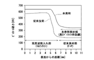
図3に、素材の表面からの距離とビッカース硬さHVとの関係の一例を示す。なお、図3には、本発明に係る高周波焼入れ部品用素材の焼入れ・焼き戻し後のビッカース硬さに加えて、従来の材料の焼入れ・焼き戻し後のビッカース硬さも示した。
図3より、本発明に係る高周波焼入れ部品用素材は、従来の材料に比べて、素材部の硬さ及び表層部の硬さが高いことがわかる。素材部の硬さが向上しているのは、時効処理によりMo、V炭化物を析出させているためである。また、表層部の硬さが向上しているのは、素材部の耐力が向上しているためである。
FIG. 3 shows an example of the relationship between the distance from the surface of the material and the Vickers hardness HV. In addition to the Vickers hardness of the material for induction hardening parts according to the present invention after quenching and tempering, FIG. 3 also shows the Vickers hardness of the conventional material after quenching and tempering.
From FIG. 3, it can be seen that the material for induction hardening parts according to the present invention is higher in hardness of the material portion and hardness of the surface layer portion as compared with the conventional material. The hardness of the material portion is improved because Mo and V carbides are precipitated by aging treatment. Further, the hardness of the surface layer portion is improved because the resistance of the material portion is improved.
以上、本発明の実施の形態について詳細に説明したが、本発明は上記実施の形態に何ら限定されるものではなく、本発明の要旨を逸脱しない範囲内で種々の改変が可能である。 As mentioned above, although embodiment of this invention was described in detail, this invention is not limited at all to the said embodiment, A various change is possible within the range which does not deviate from the summary of this invention.
本発明に係る高周波焼入れ部品用素材は、自動車用のギア、ステアリング用ラック、ドライブシャフト等に用いることができる。 The material for induction hardening parts according to the present invention can be used as a gear for an automobile, a rack for steering, a drive shaft and the like.
Claims (4)
(1)前記高周波焼入れ部品用素材は、
0.20≦C≦0.60mass%
0.01≦Si≦2.00mass%、
0.20≦Mn≦3.00mass%、
P≦0.200mass%、
0.001≦S≦0.200mass%、
0.01≦Cu≦2.00mass%、
0.01≦Ni≦3.00mass%、
0.10≦Cr≦3.00mass%、
0.10≦Mo≦2.00mass%、及び、
0.10≦V≦1.00mass%
を含み、残部がFe及び不可避的不純物からなる。
(2)前記高周波焼入れ部品用素材は、次の式(a)及び式(b)の関係を満たす。
20≦A≦40 ・・・(a)
但し、A=3×[C]+10×[Mn]+2×[Cu]+2×[Ni]+12×[Cr]+9×[Mo]+2×[V]。
B≧800 ・・・(b)
但し、B=865.4×[C]+110.5×[Si]+85.9×[Mn]+37.5×[Ni]+99.8×[Cr]+199.3×[Mo]+786.2×[V]+1300.8×[Ti]+1090.6×[Nb]。 Material for induction hardening parts with the following configuration.
(1) The material for the induction hardening parts is
0.20 ≦ C ≦ 0.60 mass%
0.01 ≦ Si ≦ 2.00 mass%,
0.20 ≦ Mn ≦ 3.00 mass%,
P ≦ 0.200 mass%,
0.001 ≦ S ≦ 0.200 mass%,
0.01 ≦ Cu ≦ 2.00 mass%,
0.01 ≦ Ni ≦ 3.00 mass%,
0.10 ≦ Cr ≦ 3.00 mass%,
0.10 ≦ Mo ≦ 2.00 mass%, and
0.10 ≦ V ≦ 1.00 mass%
And the balance consists of Fe and unavoidable impurities.
(2) The material for the induction hardening parts satisfies the relationship of the following formulas (a) and (b).
20 ≦ A ≦ 40 (a)
However, A = 3 x [C] + 10 x [Mn] + 2 x [Cu] + 2 x [Ni] + 12 x [Cr] + 9 x [Mo] + 2 x [V].
B 800 800 (b)
However, B = 865.4 x [C] + 110.5 x [Si] + 85.9 x [Mn] + 37.5 x [Ni] + 99.8 x [Cr] + 199.3 x [Mo] + 786.2 x [V] + 1300.8 × [Ti] + 1090.6 × [Nb].
0.001≦Nb≦0.300mass%
をさらに含む請求項1に記載の高周波焼入れ部品用素材。 0.001 ≦ Ti ≦ 0.300 mass%, and / or,
0.001 ≦ Nb ≦ 0.300 mass%
The material for induction hardening parts according to claim 1, further comprising
0.001≦Bi≦0.300mass%、
0.001≦Te≦0.300mass%、及び
0.001≦Ca≦0.010mass%
からなる群から選ばれるいずれか1以上の元素をさらに含む請求項1又は2に記載の高周波焼入れ部品用素材。 0.001 ≦ Pb ≦ 0.300 mass%,
0.001 ≦ Bi ≦ 0.300 mass%,
0.001 ≦ Te ≦ 0.300 mass% and 0.001 ≦ Ca ≦ 0.010 mass%
The material for induction-hardened parts according to claim 1 or 2, further comprising any one or more elements selected from the group consisting of
をさらに含む請求項1から3までのいずれか1項に記載の高周波焼入れ部品用素材。 0.0001 B B 100 0.0100 mass%
The material for induction hardening parts according to any one of claims 1 to 3, further comprising
Priority Applications (1)
| Application Number | Priority Date | Filing Date | Title |
|---|---|---|---|
| JP2017083120A JP2018178228A (en) | 2017-04-19 | 2017-04-19 | Raw material for high frequency induction hardening component |
Applications Claiming Priority (1)
| Application Number | Priority Date | Filing Date | Title |
|---|---|---|---|
| JP2017083120A JP2018178228A (en) | 2017-04-19 | 2017-04-19 | Raw material for high frequency induction hardening component |
Publications (1)
| Publication Number | Publication Date |
|---|---|
| JP2018178228A true JP2018178228A (en) | 2018-11-15 |
Family
ID=64281310
Family Applications (1)
| Application Number | Title | Priority Date | Filing Date |
|---|---|---|---|
| JP2017083120A Pending JP2018178228A (en) | 2017-04-19 | 2017-04-19 | Raw material for high frequency induction hardening component |
Country Status (1)
| Country | Link |
|---|---|
| JP (1) | JP2018178228A (en) |
Cited By (1)
| Publication number | Priority date | Publication date | Assignee | Title |
|---|---|---|---|---|
| CN113564496A (en) * | 2021-07-22 | 2021-10-29 | 中国铁道科学研究院集团有限公司金属及化学研究所 | Long-life railway bearing steel and preparation method thereof |
-
2017
- 2017-04-19 JP JP2017083120A patent/JP2018178228A/en active Pending
Cited By (2)
| Publication number | Priority date | Publication date | Assignee | Title |
|---|---|---|---|---|
| CN113564496A (en) * | 2021-07-22 | 2021-10-29 | 中国铁道科学研究院集团有限公司金属及化学研究所 | Long-life railway bearing steel and preparation method thereof |
| CN113564496B (en) * | 2021-07-22 | 2022-04-05 | 中国铁道科学研究院集团有限公司金属及化学研究所 | Long-life railway bearing steel and preparation method thereof |
Similar Documents
| Publication | Publication Date | Title |
|---|---|---|
| JP2719892B2 (en) | Surface carburized stainless steel alloy for high temperature, product made therefrom, and method of manufacturing the same | |
| US20130186522A1 (en) | Carburizing steel having excellent cold forgeability and method of manufacturing the same | |
| JP4808828B2 (en) | Induction hardening steel and method of manufacturing induction hardening steel parts | |
| WO2006008960A1 (en) | Component for machine structure, method for producing same, and material for high-frequency hardening | |
| JP4464862B2 (en) | Case-hardening steel with excellent grain coarsening resistance and cold workability that can be omitted for soft annealing. | |
| JP5035159B2 (en) | High-strength steel rough product and method for producing the same | |
| JP4844902B2 (en) | Piston ring material for internal combustion engines | |
| JPWO2017115842A1 (en) | Case-hardened steel, carburized parts and method for producing case-hardened steel | |
| JP6620490B2 (en) | Age-hardening steel | |
| JP5871085B2 (en) | Case-hardened steel with excellent cold forgeability and ability to suppress grain coarsening | |
| JP2004204263A (en) | Steel material for case hardening superior in cold workability and coarse-particle-preventing property in carburization, and manufacturing method therefor | |
| US20180245172A1 (en) | Age-hardenable steel, and method for manufacturing components using age-hardenable steel | |
| JP4752800B2 (en) | Non-tempered steel | |
| JP4488228B2 (en) | Induction hardening steel | |
| JP4556770B2 (en) | Carburizing steel and method for producing the same | |
| JPH11217649A (en) | Steel for induction hardening having both cold workability and high strength and its production | |
| JP6390685B2 (en) | Non-tempered steel and method for producing the same | |
| JP5679440B2 (en) | Induction hardening steel with excellent cold forgeability and excellent torsional strength after induction hardening, and method for producing the same | |
| KR101713677B1 (en) | Steel for high nitrogen air hardened bearing with high performance on rolling contact fatigue and method producing the same | |
| JP5443277B2 (en) | High-strength steel with excellent machinability and method for producing the same | |
| JP2018178228A (en) | Raw material for high frequency induction hardening component | |
| JP6459704B2 (en) | Steel for cold forging parts | |
| KR101184987B1 (en) | Steel for mechanical and structural parts having ultra fine grain size after induction hardening and method of manufacturing the same | |
| WO2023248556A1 (en) | Steel for high-frequency hardening | |
| KR101280547B1 (en) | Steel for mechanical and structural parts having ultra fine grain size after induction hardening and method of manufacturing the same |