JP2018150089A - Operation method of tower crane - Google Patents
Operation method of tower crane Download PDFInfo
- Publication number
- JP2018150089A JP2018150089A JP2017045564A JP2017045564A JP2018150089A JP 2018150089 A JP2018150089 A JP 2018150089A JP 2017045564 A JP2017045564 A JP 2017045564A JP 2017045564 A JP2017045564 A JP 2017045564A JP 2018150089 A JP2018150089 A JP 2018150089A
- Authority
- JP
- Japan
- Prior art keywords
- mast
- self
- supporting
- tower crane
- stay
- Prior art date
- Legal status (The legal status is an assumption and is not a legal conclusion. Google has not performed a legal analysis and makes no representation as to the accuracy of the status listed.)
- Granted
Links
Images


Abstract
Description
本発明は、タワークレーンの運用方法に関するものである。 The present invention relates to a method for operating a tower crane.
一般に、ビル等の建築物の建設時或いは解体時には、クライミングクレーン等のタワークレーンが使用される。 Generally, a tower crane such as a climbing crane is used when a building such as a building is constructed or dismantled.
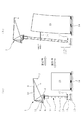
図7は従来のタワークレーンの一例を示す概略図であって、タワークレーン1は、上方へマストブロック2aを順次継ぎ足し可能なマスト2の頂部に、該マスト2に沿って昇降可能な昇降ユニット3を介して旋回体4を旋回自在に配置し、該旋回体4上にジブ5を起伏自在に取り付け、前記旋回体4に、後方へ延びるカウンタフレーム6を一体に設け、該カウンタフレーム6上に、吊荷用フック7を吊り下げるワイヤロープ8を巻上げ下げするための巻上装置9と、ジブ5の起伏用のワイヤロープ10を巻上げ下げするための起伏装置11とを設置してなる構成を有している。
FIG. 7 is a schematic view showing an example of a conventional tower crane. The
前記マスト2の底部は、基礎12上に設けられた架台13に対しボルト・ナット等の締結部材(図示せず)により固定されている。
The bottom of the mast 2 is fixed to a
一方、前記建築物としては、近年、免震装置14を備えた免震構造物15が増加している。
On the other hand, as the building, in recent years,
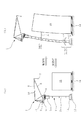
そして、例えば、前記免震構造物15の建設時において、前記タワークレーン1は、予め設定された自立できる最大の高さまでは、図7(a)に示される如く、マストブロック2aが順次継ぎ足されてマスト2単独での自立状態で免震構造物15の建設作業が進められる。
For example, at the time of construction of the
前記免震構造物15の建設作業が進行し、タワークレーン1の最大自立高さを超えると、図7(b)に示される如く、免震構造物15に対しマスト2をステー16によってつないだ状態でそれ以降の作業が続けられる。
When the construction work of the
因みに、前記免震構造物15の解体時には、タワークレーン1の最大自立高さを超えている場合、図7(b)に示される如く、免震構造物15に対しマスト2をステー16によってつないだ状態から解体作業が進められ、マストブロック2aが上方から順次撤去されていき、タワークレーン1の最大自立高さ以下になると、前記ステー16が取り外され、図7(a)に示される如く、マスト2単独での自立状態で免震構造物15の解体作業が進められる。
Incidentally, when the
尚、前述の如きタワークレーン1と関連する一般的技術水準を示すものとしては、例えば、特許文献1がある。
In addition, there exists
しかしながら、地震発生時に免震構造物15の免震装置14が働いてステー16の取付箇所が水平方向へ大きく変位した場合、タワークレーン1のマスト2下部は固定支持となっているため、マスト2、架台13、基礎12に過大なモーメントと水平力が作用してしまう虞があった。
However, when the
因みに、地震発生時に免震構造物15の変位に追従してタワークレーン1が撓むことにより許容できる強制変位量を大きくするためには、例えば、免震構造物15に対するステー16の取付箇所を高くすることが挙げられるが、該ステー16の取付箇所を高くするには、タワークレーン1の自立高さを高くする必要があり、これに伴って、マスト2、架台13、基礎12の強度を高めなければならず、コストアップにつながるという不具合を有していた。
Incidentally, in order to increase the amount of forcible displacement that can be tolerated when the
本発明は、上記従来の問題点に鑑みてなしたもので、マスト、架台、基礎に過大なモーメントと水平力が作用することを防止し得、コストダウンを図りつつ安定性向上を図り得るタワークレーンの運用方法を提供しようとするものである。 The present invention has been made in view of the above-described conventional problems, and can prevent an excessive moment and horizontal force from acting on the mast, mount, and foundation, and can improve stability while reducing costs. It is intended to provide a crane operating method.
上記目的を達成するために、本発明のタワークレーンの運用方法は、構造物の建設時或いは解体時に使用されるタワークレーンの運用方法であって、
前記構造物に対しマストをステーによってつなぐ接続工程と、
該接続工程でつないだステーより下方位置に設定された連結部でマストを上下に分断する分断工程と、
該分断工程で上下に分断したマスト間に介装された自動調心形軸受により、前記マストに作用する水平荷重及び垂直荷重を支持しつつ前記マストを前記連結部において回動自在に支持するピン支持工程と
を有することができる。
In order to achieve the above object, the tower crane operation method of the present invention is a tower crane operation method used during construction or dismantling of a structure,
A connecting step of connecting a mast to the structure by a stay;
A dividing step of dividing the mast up and down at a connecting portion set at a lower position than the stay connected in the connecting step;
A pin that supports the mast rotatably at the connecting portion while supporting a horizontal load and a vertical load acting on the mast by a self-aligning bearing interposed between the masts divided in the vertical direction in the dividing step. And a supporting step.
前記タワークレーンの運用方法において、前記構造物の建設時には、前記接続工程の前段階において、前記連結部を固定しマストを自立させる自立工程を有することができる。 In the operation method of the tower crane, when the structure is constructed, it is possible to have a self-supporting process of fixing the connecting portion and self-supporting the mast in a previous stage of the connection process.
又、前記タワークレーンの運用方法において、前記構造物の解体時には、前記ピン支持工程の後段階において、前記分断工程で分断された連結部を固定し且つ前記接続工程でつないだステーを撤去してマストを自立させる自立工程を有することができる。 In the tower crane operation method, when the structure is dismantled, the connecting portion divided in the dividing step is fixed and the stay connected in the connecting step is removed at a later stage of the pin supporting step. It can have a self-supporting process that makes the mast self-supporting.
本発明のタワークレーンの運用方法によれば、マスト、架台、基礎に過大なモーメントと水平力が作用することを防止し得、コストダウンを図りつつ安定性向上を図り得るという優れた効果を奏し得る。 According to the tower crane operation method of the present invention, it is possible to prevent an excessive moment and a horizontal force from acting on the mast, the gantry, and the foundation, and it is possible to improve the stability while reducing the cost. obtain.
以下、本発明の実施の形態を添付図面を参照して説明する。 Embodiments of the present invention will be described below with reference to the accompanying drawings.
図1〜図6は本発明のタワークレーンの運用方法の実施例であって、図中、図7と同一の符号を付した部分は同一物を表わしている。 FIGS. 1-6 is an Example of the operation method of the tower crane of this invention, Comprising: The part which attached | subjected the code | symbol same as FIG. 7 in the figure represents the same thing.
本実施例の場合、免震構造物15の建設時には、図1に示す如く、自立工程SC1と、接続工程SC2と、分断工程SC3と、ピン支持工程SC4とを有している。
In the case of the present embodiment, when the
前記自立工程SC1は、マスト2の底部(ステー16より下方位置)に設定した連結部17を固定してマスト2を自立させ、マストブロック2aを順次継ぎ足してマスト2単独での自立状態で免震構造物15の建設作業を進めるようになっている(図3(a)参照)。
In the self-supporting process SC1, the connecting
前記接続工程SC2は、前記自立工程SC1で免震構造物15の建設作業が進行し、タワークレーン1の最大自立高さを超えた場合に、前記免震構造物15に対しマスト2をステー16によってつなぐようになっている(図3(b)参照)。
In the connection process SC2, when the construction work of the
前記分断工程SC3は、前記接続工程SC2でつないだステー16より下方位置に設定された連結部17においてマスト2を上下に分断するようになっている。
In the dividing step SC3, the mast 2 is divided up and down at a connecting
前記ピン支持工程SC4は、前記分断工程SC3で上下に分断したマスト2間に介装された自動調心形軸受19により、前記マスト2に作用する水平荷重及び垂直荷重を支持しつつ前記マスト2を前記連結部17において回動自在に支持するようになっており、この状態で免震構造物15の建設作業を行うようになっている。
In the pin support step SC4, the mast 2 is supported while supporting a horizontal load and a vertical load acting on the mast 2 by a self-aligning bearing 19 interposed between the mast 2 divided in the vertical direction in the division step SC3. Is pivotally supported by the connecting
一方、本実施例の場合、免震構造物15の解体時には、図2に示す如く、接続工程SD1と、分断工程SD2と、ピン支持工程SD3と、自立工程SD4とを有している。
On the other hand, in the case of the present embodiment, when the
前記接続工程SD1は、タワークレーン1の最大自立高さを超えている免震構造物15の場合、図3(b)に示される如く、免震構造物15に対しマスト2をステー16によってつないだ状態から解体作業を進めるようになっている。
In the case of the
前記分断工程SD2は、前記接続工程SD1でつないだステー16より下方位置に設定された連結部17においてマスト2を上下に分断するようになっている。
In the dividing step SD2, the mast 2 is vertically divided at the connecting
前記ピン支持工程SD3は、前記分断工程SD2で上下に分断したマスト2間に介装された自動調心形軸受19により、前記マスト2に作用する水平荷重及び垂直荷重を支持しつつ前記マスト2を前記連結部17において回動自在に支持するようになっており、この状態で免震構造物15の解体作業を行うようになっている。
In the pin support step SD3, the mast 2 is supported while supporting a horizontal load and a vertical load acting on the mast 2 by a self-aligning bearing 19 interposed between the mast 2 divided in the vertical direction in the division step SD2. Is pivotally supported by the connecting
前記自立工程SD4は、前記ピン支持工程SD3で前記マスト2を前記連結部17において回動自在に支持した状態から、免震構造物15の解体作業を進め、マストブロック2aを上方から順次撤去していき、タワークレーン1の最大自立高さ以下になった場合に、前記ステー16を取り外し、マスト2の底部(ステー16より下方位置)に設定した連結部17を固定してマスト2を自立させ、マスト2単独での自立状態で免震構造物15の解体作業を進めるようになっている(図3(a)参照)。
In the self-supporting process SD4, from the state in which the mast 2 is pivotally supported by the connecting
上記の運用方法を実施する上での各部の構造について以下に詳述する。 The structure of each part in carrying out the above operation method will be described in detail below.
前記連結部17は、前記ステー16より下方位置に設定され且つ前記マスト2を上下に分断した状態或いは締結機構18により固定した状態に切換自在としてある。
The connecting
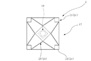
前記連結部17を固定した状態に保持する締結機構18は、図4に示す如く、上側フランジ部18aと、下側フランジ部18bと、テーパ面18cと、中間フランジ部18dと、締結部材18eとを備えている。前記上側フランジ部18aは、前記上下に分断したマスト2の上側マスト2bの下端外周部に、四隅の主材2dと一体化する形で配設されている。前記下側フランジ部18bは、前記上下に分断したマスト2の下側マスト2cの上端外周部に、四隅の主材2eと一体化する形で配設されている。前記テーパ面18cは、前記上側フランジ部18aと下側フランジ部18bの対向面に、マスト2の外周側から中心側へ向け前記対向面の間隔を狭めるよう形成されている。尚、前記テーパ面18cは、必ずしも前記上側フランジ部18aと下側フランジ部18bの対向面の両方に形成する必要はなく、前記上側フランジ部18aと下側フランジ部18bの対向面の何れか一方のみに形成しても良い。前記中間フランジ部18dは、前記テーパ面18cに沿い前記上側フランジ部18aと下側フランジ部18bとの間に嵌挿自在な部材である。前記締結部材18eは、前記中間フランジ部18dと前記上側フランジ部18a及び下側フランジ部18bとを貫通して締結自在なボルト・ナット等の部材である。
As shown in FIG. 4, the
前記締結機構18による連結部17の固定状態を解除し上下に分断したマスト2間には、ラジアル荷重とアキシアル荷重を同時に負荷できる自動調心形軸受19が介装されている。前記上側マスト2bの下部には、四隅の主材2d間に掛け渡すように形成した上側十字箱型梁20が取り付けられ、同様に、前記下側マスト2cの上部には、四隅の主材2e間に掛け渡すように形成した下側十字箱型梁21が取り付けられている。前記自動調心形軸受19は、図5及び図6に示す如く、上側十字箱型梁20の下面中央部に取り付けられた球状凸面部19aと、下側十字箱型梁21の上面中央部に取り付けられ且つ前記球状凸面部19aが滑動自在に嵌入される球状凹面部19bとを備え、前記マスト2に作用する水平荷重及び垂直荷重を支持しつつ前記マスト2を前記連結部17において回動自在に支持するようになっている。尚、前記自動調心形軸受19は、上側十字箱型梁20の下面中央部に球状凹面部19bを取り付け、下側十字箱型梁21の上面中央部に球状凸面部19aを取り付けるようにしても良い。又、前記自動調心形軸受19は、ラジアル荷重とアキシアル荷重を同時に負荷できるものであれば、どのような形式の軸受であっても良い。
A self-aligning
次に、上記実施例の作用を説明する。 Next, the operation of the above embodiment will be described.
免震構造物15の建設時には、先ず、自立工程SC1として、マスト2の底部(ステー16より下方位置)に設定した連結部17が締結機構18により固定されてマスト2を自立させ、マストブロック2aを順次継ぎ足してマスト2単独での自立状態で免震構造物15の建設作業が進められる(図3(a)参照)。ここで、前記締結機構18の中間フランジ部18dが上側フランジ部18aと下側フランジ部18bとの間にテーパ面18cに沿って嵌挿され、締結部材18eが前記中間フランジ部18dと上側フランジ部18a及び下側フランジ部18bとを貫通して締結されると、前記連結部17は締結機構18により固定された状態となる。
When the
前記自立工程SC1で免震構造物15の建設作業が進行し、タワークレーン1の最大自立高さを超えると、接続工程SD1として、前記免震構造物15に対しマスト2がステー16によってつながれる(図3(b)参照)。
When construction work of the
前記接続工程SD1で前記免震構造物15に対しマスト2がステー16によってつながれると、分断工程SC3として、前記連結部17でマスト2が上下に分断される。ここで、前記締結部材18eの締結を解除し、図6の仮想線で示す如く、前記中間フランジ部18dを上側フランジ部18aと下側フランジ部18bとの間からテーパ面18cに沿ってマスト2の外周側へ引き抜くと、前記連結部17は締結機構18による固定が解除された状態となる。
When the mast 2 is connected to the
前記分断工程SC3で上下に分断したマスト2間には自動調心形軸受19が介装されているため、ピン支持工程SC4として、前記マスト2に作用する水平荷重及び垂直荷重が支持されつつ前記マスト2が前記連結部17において回動自在に支持され、この状態で免震構造物15の建設作業が行われる。ここで、地震発生時には、前記自動調心形軸受19の球状凸面部19aが球状凹面部19bに対し滑動することにより、前記マスト2が前記連結部17において回動する形となる。
Since a self-aligning
一方、タワークレーン1の最大自立高さを超えている免震構造物15の解体時には、先ず、接続工程SD1として、免震構造物15に対しマスト2がステー16によってつながれた状態から解体作業が進められる(図3(b)参照)。
On the other hand, when the
この時、分断工程SD2として、前記接続工程SD1でつないだステー16より下方位置に設定された連結部17においてマスト2は上下に分断されている。ここで、締結機構18の締結部材18eによる締結は解除され、図6の仮想線で示す如く、中間フランジ部18dは上側フランジ部18aと下側フランジ部18bとの間からテーパ面18cに沿ってマスト2の外周側へ引き抜かれており、前記連結部17は締結機構18による固定が解除された状態となっている。
At this time, as the dividing step SD2, the mast 2 is vertically divided at the connecting
前記分断工程SD2で上下に分断したマスト2間には自動調心形軸受19が介装されているため、ピン支持工程SD3として、前記マスト2に作用する水平荷重及び垂直荷重が支持されつつ前記マスト2が前記連結部17において回動自在に支持され、この状態で免震構造物15の解体作業が行われる。
Since a self-aligning
前記ピン支持工程SD3で前記マスト2が前記連結部17において回動自在に支持された状態から、免震構造物15の解体作業が進められ、マストブロック2aが上方から順次撤去されていき、タワークレーン1の最大自立高さ以下になると、前記ステー16が取り外され、マスト2の底部(ステー16より下方位置)に設定した連結部17が固定され、自立工程SD4として、マスト2単独での自立状態で前記免震構造物15の解体作業が進められる(図3(a)参照)。ここで、前記締結機構18の中間フランジ部18dが上側フランジ部18aと下側フランジ部18bとの間にテーパ面18cに沿って嵌挿され、締結部材18eが前記中間フランジ部18dと上側フランジ部18a及び下側フランジ部18bとを貫通して締結されると、前記連結部17は締結機構18により固定された状態となる。
From the state where the mast 2 is rotatably supported at the connecting
これにより、本実施例では、地震発生時に免震構造物15の免震装置14が働いてステー16の取付箇所が水平方向へ大きく変位したとしても、タワークレーン1のマスト2下部は固定支持ではなくピン支持となっているため、免震構造物15の建設時或いは解体時の何れの場合であっても、マスト2、架台13、基礎12に過大なモーメントと水平力が作用してしまうことがなくなる。
As a result, in this embodiment, even if the
これに伴い、例えば、免震構造物15に対するステー16の取付箇所を高くして、地震発生時に免震構造物15の変位に追従してタワークレーン1が撓むことにより許容できる強制変位量を大きくする必要がなくなるため、タワークレーン1の自立高さを高くしなくて済み、マスト2、架台13、基礎12の強度を低く抑えることが可能となり、コストアップが避けられる。
Along with this, for example, the mounting position of the
こうして、マスト2、架台13、基礎12に過大なモーメントと水平力が作用することを防止し得、コストダウンを図りつつ安定性向上を図り得る。
In this way, it is possible to prevent an excessive moment and horizontal force from acting on the mast 2, the
尚、本発明のタワークレーンの運用方法は、上述の実施例にのみ限定されるものではなく、免震構造物に限らず、耐震、制震機能を有する構造物にも適用可能なこと等、その他、本発明の要旨を逸脱しない範囲内において種々変更を加え得ることは勿論である。 In addition, the operation method of the tower crane of the present invention is not limited to the above-described embodiments, and is not limited to seismic isolation structures, but can be applied to structures having seismic resistance and vibration control functions, etc. In addition, it goes without saying that various changes can be made without departing from the scope of the present invention.
1 タワークレーン
2 マスト
15 免震構造物(構造物)
16 ステー
17 連結部
18 締結機構
19 自動調心形軸受
SC1 自立工程
SC2 接続工程
SC3 分断工程
SC4 ピン支持工程
SD1 接続工程
SD2 分断工程
SD3 ピン支持工程
SD4 自立工程
1 Tower crane 2
16
Claims (3)
前記構造物に対しマストをステーによってつなぐ接続工程と、
該接続工程でつないだステーより下方位置に設定された連結部でマストを上下に分断する分断工程と、
該分断工程で上下に分断したマスト間に介装された自動調心形軸受により、前記マストに作用する水平荷重及び垂直荷重を支持しつつ前記マストを前記連結部において回動自在に支持するピン支持工程と
を有することを特徴とするタワークレーンの運用方法。 A tower crane operation method used during construction or dismantling of a structure,
A connecting step of connecting a mast to the structure by a stay;
A dividing step of dividing the mast up and down at a connecting portion set at a lower position than the stay connected in the connecting step;
A pin that supports the mast rotatably at the connecting portion while supporting a horizontal load and a vertical load acting on the mast by a self-aligning bearing interposed between the masts divided in the vertical direction in the dividing step. A tower crane operating method comprising: a supporting step.
Priority Applications (1)
| Application Number | Priority Date | Filing Date | Title |
|---|---|---|---|
| JP2017045564A JP6882019B2 (en) | 2017-03-10 | 2017-03-10 | How to operate a tower crane |
Applications Claiming Priority (1)
| Application Number | Priority Date | Filing Date | Title |
|---|---|---|---|
| JP2017045564A JP6882019B2 (en) | 2017-03-10 | 2017-03-10 | How to operate a tower crane |
Publications (2)
| Publication Number | Publication Date |
|---|---|
| JP2018150089A true JP2018150089A (en) | 2018-09-27 |
| JP6882019B2 JP6882019B2 (en) | 2021-06-02 |
Family
ID=63681289
Family Applications (1)
| Application Number | Title | Priority Date | Filing Date |
|---|---|---|---|
| JP2017045564A Active JP6882019B2 (en) | 2017-03-10 | 2017-03-10 | How to operate a tower crane |
Country Status (1)
| Country | Link |
|---|---|
| JP (1) | JP6882019B2 (en) |
Cited By (4)
| Publication number | Priority date | Publication date | Assignee | Title |
|---|---|---|---|---|
| JP2019112198A (en) * | 2017-12-25 | 2019-07-11 | 株式会社竹中工務店 | Climbing construction method of tower crane |
| JP2020070114A (en) * | 2018-10-29 | 2020-05-07 | ポルタパーク株式会社 | Work ship with tower crane and its operating method |
| JP2020097468A (en) * | 2018-12-18 | 2020-06-25 | Ihi運搬機械株式会社 | Bottom pin supporting structure of tower crane |
| TWI834746B (en) | 2018-10-29 | 2024-03-11 | 日商塔駐車股份有限公司 | Work platform vessel equipped with crane and method of using the crane |
Citations (5)
| Publication number | Priority date | Publication date | Assignee | Title |
|---|---|---|---|---|
| JPS6445690U (en) * | 1987-09-16 | 1989-03-20 | ||
| JP2009057754A (en) * | 2007-08-31 | 2009-03-19 | Sansei Kenki Kk | Strut unit connection device adaptable to base-isolated structure |
| JP2009214950A (en) * | 2008-03-07 | 2009-09-24 | Ishikawajima Transport Machinery Co Ltd | Base isolated supporting structure of crane |
| JP2009249153A (en) * | 2008-04-10 | 2009-10-29 | Ishikawajima Transport Machinery Co Ltd | Base isolation support device of crane |
| JP2012254836A (en) * | 2011-06-07 | 2012-12-27 | Shimizu Corp | Mast support structure of tower crane and support method of tower crane |
-
2017
- 2017-03-10 JP JP2017045564A patent/JP6882019B2/en active Active
Patent Citations (5)
| Publication number | Priority date | Publication date | Assignee | Title |
|---|---|---|---|---|
| JPS6445690U (en) * | 1987-09-16 | 1989-03-20 | ||
| JP2009057754A (en) * | 2007-08-31 | 2009-03-19 | Sansei Kenki Kk | Strut unit connection device adaptable to base-isolated structure |
| JP2009214950A (en) * | 2008-03-07 | 2009-09-24 | Ishikawajima Transport Machinery Co Ltd | Base isolated supporting structure of crane |
| JP2009249153A (en) * | 2008-04-10 | 2009-10-29 | Ishikawajima Transport Machinery Co Ltd | Base isolation support device of crane |
| JP2012254836A (en) * | 2011-06-07 | 2012-12-27 | Shimizu Corp | Mast support structure of tower crane and support method of tower crane |
Cited By (8)
| Publication number | Priority date | Publication date | Assignee | Title |
|---|---|---|---|---|
| JP2019112198A (en) * | 2017-12-25 | 2019-07-11 | 株式会社竹中工務店 | Climbing construction method of tower crane |
| JP7085346B2 (en) | 2017-12-25 | 2022-06-16 | 株式会社竹中工務店 | Climbing method for tower cranes |
| JP2020070114A (en) * | 2018-10-29 | 2020-05-07 | ポルタパーク株式会社 | Work ship with tower crane and its operating method |
| WO2020090611A1 (en) * | 2018-10-29 | 2020-05-07 | ポルタパーク株式会社 | Work ship having tower crane and crane operating method therefor |
| JP7197118B2 (en) | 2018-10-29 | 2022-12-27 | ポルタパーク株式会社 | Work barge equipped with a crane and its crane operation method |
| TWI834746B (en) | 2018-10-29 | 2024-03-11 | 日商塔駐車股份有限公司 | Work platform vessel equipped with crane and method of using the crane |
| JP2020097468A (en) * | 2018-12-18 | 2020-06-25 | Ihi運搬機械株式会社 | Bottom pin supporting structure of tower crane |
| JP7253909B2 (en) | 2018-12-18 | 2023-04-07 | Ihi運搬機械株式会社 | Tower crane floor climbing method |
Also Published As
| Publication number | Publication date |
|---|---|
| JP6882019B2 (en) | 2021-06-02 |
Similar Documents
| Publication | Publication Date | Title |
|---|---|---|
| JP5675041B2 (en) | How to raise a crane boom | |
| JP5580975B2 (en) | How to raise a crane boom | |
| JP6655840B2 (en) | Crane equipment used at the construction site of reinforced concrete buildings | |
| JP2018150089A (en) | Operation method of tower crane | |
| CN106006455B (en) | The hydraulic elevator without scaffold building template frame can be achieved | |
| JP5825864B2 (en) | Tower crane mast support structure and tower crane support method | |
| US10392233B2 (en) | Crane tower | |
| CN206999277U (en) | A kind of wallboard turning device | |
| JP2010242429A (en) | Demolition method for steel tower | |
| KR101922047B1 (en) | bracing removing apparatus of tower crane | |
| JP7253909B2 (en) | Tower crane floor climbing method | |
| CN204416960U (en) | A kind of bipod mast Lift-on/Lift-off System being convenient to movement | |
| JP4669692B2 (en) | Climbing type jib crane | |
| CN104609318A (en) | Herringbone mast hoisting system convenient to move | |
| KR100427751B1 (en) | An installation beam of tower-crane for an outer wall | |
| JP4914130B2 (en) | Climbing crane | |
| JP2021031234A (en) | Panel standing tool and panel standing method using the panel standing tool | |
| CN214243539U (en) | Be used for maintenance of equipment auxiliary device in marine engine room bottom | |
| CN204416962U (en) | A kind of bipod mast being convenient to movement | |
| JP6300356B2 (en) | Steel tower dismantling and assembly equipment | |
| JP6814717B2 (en) | How to install horizontal members and how to build a building frame | |
| JP5264299B2 (en) | Crane jib support equipment | |
| JP3532161B2 (en) | Tower construction machine and tower construction method | |
| CN216583910U (en) | Movable lifting type hoisting tool | |
| JP6159197B2 (en) | Steel tower dismantling method and dismantling apparatus |
Legal Events
| Date | Code | Title | Description |
|---|---|---|---|
| A621 | Written request for application examination |
Free format text: JAPANESE INTERMEDIATE CODE: A621 Effective date: 20191218 |
|
| A977 | Report on retrieval |
Free format text: JAPANESE INTERMEDIATE CODE: A971007 Effective date: 20200917 |
|
| A131 | Notification of reasons for refusal |
Free format text: JAPANESE INTERMEDIATE CODE: A131 Effective date: 20201006 |
|
| A521 | Request for written amendment filed |
Free format text: JAPANESE INTERMEDIATE CODE: A523 Effective date: 20201105 |
|
| A131 | Notification of reasons for refusal |
Free format text: JAPANESE INTERMEDIATE CODE: A131 Effective date: 20210105 |
|
| A521 | Request for written amendment filed |
Free format text: JAPANESE INTERMEDIATE CODE: A523 Effective date: 20210225 |
|
| TRDD | Decision of grant or rejection written | ||
| A01 | Written decision to grant a patent or to grant a registration (utility model) |
Free format text: JAPANESE INTERMEDIATE CODE: A01 Effective date: 20210427 |
|
| A61 | First payment of annual fees (during grant procedure) |
Free format text: JAPANESE INTERMEDIATE CODE: A61 Effective date: 20210506 |
|
| R150 | Certificate of patent or registration of utility model |
Ref document number: 6882019 Country of ref document: JP Free format text: JAPANESE INTERMEDIATE CODE: R150 |