JP2018113600A - Light emitting device, imaging device, information transmission system, information transmission method, and program - Google Patents
Light emitting device, imaging device, information transmission system, information transmission method, and program Download PDFInfo
- Publication number
- JP2018113600A JP2018113600A JP2017003085A JP2017003085A JP2018113600A JP 2018113600 A JP2018113600 A JP 2018113600A JP 2017003085 A JP2017003085 A JP 2017003085A JP 2017003085 A JP2017003085 A JP 2017003085A JP 2018113600 A JP2018113600 A JP 2018113600A
- Authority
- JP
- Japan
- Prior art keywords
- light
- light emission
- movement
- light emitting
- unit
- Prior art date
- Legal status (The legal status is an assumption and is not a legal conclusion. Google has not performed a legal analysis and makes no representation as to the accuracy of the status listed.)
- Pending
Links
Images


Classifications
-
- H—ELECTRICITY
- H04—ELECTRIC COMMUNICATION TECHNIQUE
- H04B—TRANSMISSION
- H04B10/00—Transmission systems employing electromagnetic waves other than radio-waves, e.g. infrared, visible or ultraviolet light, or employing corpuscular radiation, e.g. quantum communication
- H04B10/60—Receivers
- H04B10/66—Non-coherent receivers, e.g. using direct detection
-
- H—ELECTRICITY
- H04—ELECTRIC COMMUNICATION TECHNIQUE
- H04B—TRANSMISSION
- H04B10/00—Transmission systems employing electromagnetic waves other than radio-waves, e.g. infrared, visible or ultraviolet light, or employing corpuscular radiation, e.g. quantum communication
- H04B10/11—Arrangements specific to free-space transmission, i.e. transmission through air or vacuum
- H04B10/114—Indoor or close-range type systems
- H04B10/116—Visible light communication
-
- G—PHYSICS
- G06—COMPUTING; CALCULATING OR COUNTING
- G06T—IMAGE DATA PROCESSING OR GENERATION, IN GENERAL
- G06T7/00—Image analysis
- G06T7/20—Analysis of motion
- G06T7/246—Analysis of motion using feature-based methods, e.g. the tracking of corners or segments
- G06T7/248—Analysis of motion using feature-based methods, e.g. the tracking of corners or segments involving reference images or patches
-
- G—PHYSICS
- G06—COMPUTING; CALCULATING OR COUNTING
- G06T—IMAGE DATA PROCESSING OR GENERATION, IN GENERAL
- G06T7/00—Image analysis
- G06T7/70—Determining position or orientation of objects or cameras
- G06T7/73—Determining position or orientation of objects or cameras using feature-based methods
- G06T7/74—Determining position or orientation of objects or cameras using feature-based methods involving reference images or patches
-
- H—ELECTRICITY
- H04—ELECTRIC COMMUNICATION TECHNIQUE
- H04B—TRANSMISSION
- H04B10/00—Transmission systems employing electromagnetic waves other than radio-waves, e.g. infrared, visible or ultraviolet light, or employing corpuscular radiation, e.g. quantum communication
- H04B10/50—Transmitters
- H04B10/501—Structural aspects
- H04B10/502—LED transmitters
-
- H—ELECTRICITY
- H04—ELECTRIC COMMUNICATION TECHNIQUE
- H04B—TRANSMISSION
- H04B10/00—Transmission systems employing electromagnetic waves other than radio-waves, e.g. infrared, visible or ultraviolet light, or employing corpuscular radiation, e.g. quantum communication
- H04B10/50—Transmitters
- H04B10/516—Details of coding or modulation
-
- H—ELECTRICITY
- H04—ELECTRIC COMMUNICATION TECHNIQUE
- H04N—PICTORIAL COMMUNICATION, e.g. TELEVISION
- H04N23/00—Cameras or camera modules comprising electronic image sensors; Control thereof
- H04N23/50—Constructional details
- H04N23/55—Optical parts specially adapted for electronic image sensors; Mounting thereof
-
- H—ELECTRICITY
- H04—ELECTRIC COMMUNICATION TECHNIQUE
- H04N—PICTORIAL COMMUNICATION, e.g. TELEVISION
- H04N23/00—Cameras or camera modules comprising electronic image sensors; Control thereof
- H04N23/60—Control of cameras or camera modules
-
- H—ELECTRICITY
- H04—ELECTRIC COMMUNICATION TECHNIQUE
- H04N—PICTORIAL COMMUNICATION, e.g. TELEVISION
- H04N23/00—Cameras or camera modules comprising electronic image sensors; Control thereof
- H04N23/60—Control of cameras or camera modules
- H04N23/617—Upgrading or updating of programs or applications for camera control
Abstract
Description
本発明は、発光装置、撮像装置、情報伝送システム、情報伝送方法及びプログラムに関する。 The present invention relates to a light emitting device, an imaging device, an information transmission system, an information transmission method, and a program.
従来より、可視光を通信媒体として情報伝送を行う技術が知られている(例えば特許文献1参照)。 2. Description of the Related Art Conventionally, a technique for transmitting information using visible light as a communication medium is known (see, for example, Patent Document 1).
上記特許文献1は、可視光通信を行う装置間の位置が変化することについては考慮されていないが、位置が変化するケースを想定した場合であっても受光装置側における発光位置の捕捉は確実に行われることが望ましい。より具体的手法としては、発光装置側が短い周期で発光し、これに応じて撮像装置が短い周期で撮影することが考えられるが、このように発光装置における発光周期及び撮像装置における撮影周期を短くすることは、双方の装置において処理負荷を増加させるという問題があった。 Although Patent Document 1 does not take into consideration that the position between devices that perform visible light communication changes, even when the case where the position changes is assumed, the capture of the light emission position on the light receiving device side is certain. It is desirable to be performed. As a more specific method, it is conceivable that the light emitting device emits light with a short cycle, and the imaging device takes a picture with a short cycle accordingly. In this way, the light emission cycle of the light emitting device and the shooting cycle of the imaging device are shortened. Doing so has the problem of increasing the processing load on both devices.
本願発明はこのような問題点に鑑みてなされたものであり、発光装置と撮像装置の双方の位置関係が変化する場合であっても、撮像装置側での発光装置の発光位置の捕捉を容易にすることを目的とする。 The present invention has been made in view of such problems, and even when the positional relationship between both the light emitting device and the imaging device changes, it is easy to capture the light emitting position of the light emitting device on the imaging device side. The purpose is to.
上記目的を達成するため、本発明に係る発光装置は、
光を通信媒体として任意の情報を外部の撮像装置へ送信する発光装置であって、
発光手段と、
前記発光手段の移動を検知する移動検知手段と、
前記移動検知手段の検知結果に応じて、前記撮像装置による前記任意の情報の受信のための発光位置の捕捉が可能となるように、前記発光手段の発光態様を変更する発光制御手段と、
を備えることを特徴とする。
In order to achieve the above object, a light emitting device according to the present invention includes:
A light emitting device that transmits arbitrary information to an external imaging device using light as a communication medium,
A light emitting means;
Movement detecting means for detecting movement of the light emitting means;
A light emission control unit that changes a light emission mode of the light emitting unit so that a light emission position for receiving the arbitrary information can be captured by the imaging device according to a detection result of the movement detection unit;
It is characterized by providing.
上記目的を達成するため、本発明に係る撮像装置は、
所定の撮影周期で撮像するとともに光を通信媒体として任意の情報を送信する発光装置からの光を受信する撮像装置であって、
撮影手段と、
前記撮影手段により撮影された画像に含まれる前記発光装置からの光の像から前記任意の情報を取得する情報取得手段と、
前記所定の撮影周期の撮影により取得された複数の画像から前記光の像の移動を検知する移動検知手段と、
前記移動検知手段の検知結果に応じて、前記所定の撮影周期を変更する撮影周期制御手段と、
を備えることを特徴とする。
In order to achieve the above object, an imaging apparatus according to the present invention provides:
An imaging device that receives light from a light emitting device that picks up an image at a predetermined shooting period and transmits arbitrary information using light as a communication medium,
Photographing means;
Information acquisition means for acquiring the arbitrary information from an image of light from the light emitting device included in the image captured by the imaging means;
Movement detecting means for detecting movement of the image of the light from a plurality of images acquired by shooting at the predetermined shooting period;
An imaging cycle control unit that changes the predetermined imaging cycle according to a detection result of the movement detection unit;
It is characterized by providing.
上記目的を達成するため、本発明に係る情報伝送システムは、
発光装置と撮像装置との間で、光を通信媒体として任意の情報を伝送する情報伝送システムであって、
前記発光装置は、
発光手段と、
前記発光手段の移動を検知する第1の移動検知手段と、
前記第1の移動検知手段の検知結果に応じて、前記撮像装置による前記任意の情報の受信のための発光位置の捕捉が可能となるように、前記発光手段の発光態様を変更する発光制御手段と、
を備えることを特徴とする。
In order to achieve the above object, an information transmission system according to the present invention includes:
An information transmission system that transmits arbitrary information using light as a communication medium between a light emitting device and an imaging device,
The light emitting device
A light emitting means;
First movement detecting means for detecting movement of the light emitting means;
Light emission control means for changing the light emission mode of the light emitting means so that the light emitting position for receiving the arbitrary information can be captured by the imaging device according to the detection result of the first movement detecting means. When,
It is characterized by providing.
上記目的を達成するため、本発明に係る情報伝送方法は、
発光装置と撮像装置との間で、光を通信媒体として任意の情報を伝送する情報伝送システムにおける情報伝送方法であって、
前記発光装置が発光部の移動を検知する移動検知ステップと、
前記発光装置が前記移動検知ステップでの検知結果に応じて、前記撮像装置による前記任意の情報の受信のための発光位置の捕捉が可能となるように、前記発光部の発光態様を変更する発光制御ステップと、
を含むことを特徴とする。
In order to achieve the above object, an information transmission method according to the present invention includes:
An information transmission method in an information transmission system for transmitting arbitrary information using light as a communication medium between a light emitting device and an imaging device,
A movement detecting step in which the light emitting device detects movement of the light emitting unit;
Light emission that changes the light emission mode of the light emitting unit so that the light emitting device can capture the light emission position for receiving the arbitrary information by the imaging device according to the detection result in the movement detection step. Control steps;
It is characterized by including.
上記目的を達成するため、本発明に係るプログラムは、
外部の撮像装置へ光を通信媒体として任意の情報を送信する発光装置が備えるコンピュータを、
発光部の移動を検知する移動検知手段、
前記移動検知手段の検知結果に応じて、前記撮像装置による前記任意の情報の受信のための発光位置の捕捉が可能となるように、前記発光部の発光態様を変更する発光制御手段、
として機能させることを特徴とする。
In order to achieve the above object, a program according to the present invention provides:
A computer provided in a light emitting device that transmits arbitrary information using light as a communication medium to an external imaging device,
A movement detecting means for detecting movement of the light emitting unit;
A light emission control unit that changes a light emission mode of the light emitting unit so that a light emission position for receiving the arbitrary information can be captured by the imaging device according to a detection result of the movement detection unit.
It is made to function as.
上記目的を達成するため、本発明に係るプログラムは、
撮影部にて所定の撮影周期で撮像するとともに、光を通信媒体として任意の情報を送信する発光装置からの光を受光する撮像装置が備えるコンピュータを、
前記撮影部により撮影された画像に含まれる前記発光装置からの光の像から前記任意の情報を取得する情報取得手段、
前記所定の撮影周期の撮影により取得された複数の画像から前記光の像の移動を検知する移動検知手段、
前記移動検知手段の検知結果に応じて、前記所定の撮影周期を変更する撮影周期制御手段、
として機能させることを特徴とする。
In order to achieve the above object, a program according to the present invention provides:
A computer provided with an imaging device that receives light from a light emitting device that transmits arbitrary information using light as a communication medium while capturing an image at a photographing unit in a photographing unit,
Information acquisition means for acquiring the arbitrary information from an image of light from the light emitting device included in the image captured by the imaging unit;
A movement detecting means for detecting movement of the image of the light from a plurality of images acquired by shooting at the predetermined shooting period;
An imaging cycle control unit that changes the predetermined imaging cycle according to a detection result of the movement detection unit,
It is made to function as.
本発明によれば、双方の位置関係が変化する場合であっても、発光装置の発光位置の捕捉を容易なものとすることが可能となる。 According to the present invention, it is possible to easily capture the light emission position of the light emitting device even when the positional relationship between the two changes.
以下、図面を参照して、本発明の実施形態に係る情報処理システムとしての可視光通信システムを説明する。 Hereinafter, a visible light communication system as an information processing system according to an embodiment of the present invention will be described with reference to the drawings.
図1は、可視光通信システムの構成を示す図である。図1に示すように、可視光通信システム1は、サーバ200と、移動可能な機器(移動機器)100a、100b、100c(以下、移動機器100a、100b、100cのそれぞれを限定しない場合には、適宜「移動機器100」と称する)と、サーバ200とを含んで構成される。移動機器100aは、LED(Light Emitting Diode)102aを含み、移動機器100bは、LED102bを含み、移動機器100cは、LED102cを含む(以下、LED102a、102b、102cのそれぞれを限定しない場合には、適宜「LED102」と称する)。サーバ200は、撮影部201を含む。移動機器100は、発光装置に対応し、サーバ200は、撮像装置に対応する。
FIG. 1 is a diagram illustrating a configuration of a visible light communication system. As shown in FIG. 1, the visible light communication system 1 includes a
本実施形態において、移動機器100内のLED102が送信対象の情報に対応する光を発することにより情報を送信する。一方、サーバ200では、サーバ200内の撮影部201が撮影を行い、撮影により得られた光の画像から情報を取得するとともに、移動機器100の発光位置の捕捉をする。
In the present embodiment, the
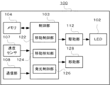
図2は、移動機器100の構成の一例を示す図である。図2に示すように、移動機器100は、LED102、制御部103、メモリ104、速度センサ107、通信部108、駆動部112、移動部128を含む。
FIG. 2 is a diagram illustrating an example of the configuration of the mobile device 100. As illustrated in FIG. 2, the mobile device 100 includes an
制御部103は、例えばCPU(Central Processing Unit)によって構成される。制御部103は、メモリ104に記憶されたプログラム(例えば、後述する図4に示す移動機器100の動作を実現するためのプログラム)に従ってソフトウェア処理を実行することにより、移動機器100が具備する各種機能を制御する。
The
メモリ104は、例えばRAM(Random Access Memory)やROM(Read Only Memory)である。メモリ104は、移動機器100における制御等に用いられる各種情報(プログラム等)を記憶する。速度センサ107は、移動機器100の速度を検出する。通信部108は、例えばLAN(Local Area Network)カードである。通信部108は、他の通信装置との間で通信を行う。
The
制御部103には、移動制御部122、移動検知部124及び発光制御部126が構成される。移動制御部122は、通信部108によって受信された移動制御用の情報等に基づいて、移動機器100の移動を制御する。移動検知部124は、速度センサ107による検出結果に基づき、移動機器100の移動の有無、及び移動した際のその移動速度を取得する。尚、移動の検出対象は移動機100でも良く、移動器100とLED102(発光部)とが相対的に位置変化する機構を搭載している場合は、LED102を移動の検出対象としても良い。発光制御部126は、移動機器100の速度に応じて、LED102が発する色相の時間的な変化を示す任意の情報として所定の光を発光する発光パターンを決定する。更に、発光制御部126は、決定した発光パターンの情報を駆動部112へ出力する。
The
駆動部112は、発光制御部126からの発光パターンの情報に応じて、LED102が発する光の色相を時間的に変化させるための駆動信号を生成する。LED102は、駆動部112から出力される駆動信号に応じて、時間的に色相が変化する光を発する。移動部128は、移動機器100を移動させるための構成を備え、端的にはモーターや駆動回路、及び駆動手段を備える。
The
図3は、サーバ200の構成の一例を示す図である。図3に示すように、サーバ200は、撮影部201、制御部202、画像処理部204、メモリ205、操作部206、表示部207及び通信部208を含む。
FIG. 3 is a diagram illustrating an example of the configuration of the
撮影部201は、レンズ203を含む。レンズ203は、ズームレンズ等により構成される。レンズ203は、操作部206からのズーム制御操作、及び、制御部202による合焦制御により移動する。レンズ203の移動によって撮影部201が撮影する撮影画角や光学像が制御される。
The
撮影部201は、受光面に規則的に二次元配列された複数の受光素子により構成される。受光素子は、例えば、CCD(Charge Coupled Device)、CMOS(Complementary Metal Oxide Semiconductor)等の撮影デバイスである。撮影部201は、レンズ203を介して入光された光学像を、制御部202からの制御信号に基づいて所定範囲の撮影画角で撮影(受光)し、その撮影画角内の画像信号をデジタルデータに変換してフレームを生成する。また、撮影部201は、撮影とフレームの生成とを時間的に連続して行い、連続するフレームを画像処理部204に出力する。
The
画像処理部204は、制御部202からの制御信号に基づいて、撮影部201から出力されたフレーム(デジタルデータ)をそのまま制御部202へ出力するとともに、当該フレームについて、表示部207にスルー画像として表示させるべく、画質や画像サイズを調整して制御部202へ出力する。また、画像処理部204は、操作部206からの記録指示操作に基づく制御信号が入力されると、記録指示された時点の撮影部201における撮影画角内、あるいは、表示部207に表示される表示範囲内の光学像を、例えば、JPEG(Joint Photographic Experts Group)等の圧縮符号化方式にて符号化、ファイル化する機能を有する。
Based on the control signal from the
制御部202は、例えばCPUによって構成される。制御部202は、メモリ205に記憶されたプログラム(例えば、後述する図9に示すサーバ200の動作を実現するためのプログラム)に従ってソフトウェア処理を実行することにより、サーバ200が具備する各種機能を制御する。
The
メモリ205は、例えばRAMやROMである。メモリ205は、サーバ200における制御等に用いられる各種情報(プログラム等)を記憶する。通信部208は、例えばLANカードである。通信部208は、外部の通信装置との間で通信を行う。
The
操作部206は、テンキーやファンクションキー等によって構成され、ユーザの操作内容を入力するために用いられるインタフェースである。表示部207は、例えば、LCD(Liquid Crystal Display)、PDP(Plasma Display Panel)、EL(Electroluminescence)ディスプレイ等によって構成される。表示部207は、制御部202から出力された画像信号に従って画像を表示する。
The
制御部202には、移動検知部232、情報取得部234及び撮影周期制御部236が構成される。移動検知部232は、画像処理部204からのフレームの時間的な変化から移動機器100の発光位置の捕捉をしつつ、当該移動機器100の速度を検知する。情報取得部234は、移動検知部232によって検知された移動機器100の速度に応じた発光パターンを判別する。更に、情報取得部234は、移動機器100内のLED102が、判別した発光パターンで色相が時間的に変化する光を発しているものと見なし、判別した発光パターンに応じた情報取得を行う。撮影周期制御部236は、移動検知部232によって検知された移動機器100の速度に応じて撮影部201による撮影周期を決定する。更に、撮影周期制御部236は、決定した撮影周期で撮影するように撮影部201を制御する。
The
次に、可視光通信システム1の動作を説明する。図4は、可視光通信システム1内の移動機器100による送信処理の動作の一例を示すフローチャートである。 Next, the operation of the visible light communication system 1 will be described. FIG. 4 is a flowchart illustrating an example of operation of transmission processing by the mobile device 100 in the visible light communication system 1.
移動機器100内の速度センサ107は、移動部128の動作に基づく移動機器100の速度を検出し、制御部103へ出力する(ステップS101)。制御部103内の移動検知部124は、速度センサ107からの移動機器100の速度を取得する。更に、移動検知部124は、取得した移動機器100の速度に基づいて、移動機器100が停止しているか否かを判定する(ステップS102)。
The
移動機器100が停止していると判定された場合(ステップS102;YES)、制御部103内の発光制御部126は、LED102が第1発光パターンに応じた発光を行うように当該LED102を制御する(ステップS103)。第1発光パターンは、送信対象のデータの送信のために用いられるものであるが、サーバ200における移動機器100の発光位置の捕捉に用いることも可能となっている。
When it is determined that the mobile device 100 is stopped (step S102; YES), the light
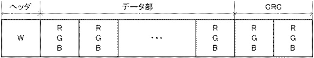
図5は、第1発光パターンの一例を示す図である。図5に示す第1発光パターンは、発光周波数(1つの色相での発光の期間)が2[Hz]以下である。第1発光パターンは、ヘッダとしての1回の消灯(Bk)と、データ部としての所定回数の赤(R)、緑(G)、青(B)の何れかの発光と、誤り訂正用のCRC(Cyclic Redundancy Check)としての2回の赤、緑、青の何れかの発光を含んで構成される。 FIG. 5 is a diagram illustrating an example of the first light emission pattern. In the first light emission pattern shown in FIG. 5, the light emission frequency (light emission period in one hue) is 2 [Hz] or less. The first light emission pattern includes one turn-off (Bk) as a header, a predetermined number of red (R), green (G), and blue (B) light emission as a data portion, and error correction. It is configured to include either red, green, or blue light emission as a CRC (Cyclic Redundancy Check).
発光制御部126は、送信対象のデータ(例えば、移動機器100の状態を示すデータ)をビットデータ列に符号化し、当該ビットデータ列に基づくデジタル変調を行って、赤、緑、青の何れかの発光の組み合わせを決定する。更に、発光制御部126は、決定した発光の組み合わせを第1発光パターンのデータ部に割り当てるとともに、CRCに対応する色の発光を割り当てる。次に、発光制御部126は、第1発光パターンの情報を駆動部112へ出力する。
The light
駆動部112は、発光制御部126からの第1発光パターンの情報に応じて、LED102が発する光の色相を時間的に変化させるための駆動信号を生成する。LED102は、駆動部112から出力される駆動信号に基づいて、第1発光パターンに応じて時間的に色相が変化する光を発する。
The
一方、移動機器100が停止していないと判定された場合(ステップS102;NO)、移動検知部124は、取得した移動機器100の速度に基づいて、移動機器100の速度がα未満であるか否かを判定する(ステップS104)。なお、ここでいうαの値は、移動機器100が送信対象のデータを送信しながら移動しても、サーバ200において撮影部201が所定の撮像周期で撮影しても受信と発光位置の捕捉とが可能な速度を示す。
On the other hand, when it is determined that the mobile device 100 is not stopped (step S102; NO), the
移動機器100の速度がα未満であると判定された場合(ステップS104;YES)、発光制御部126は、LED102が第2発光パターンに応じた発光を行うように当該LED102を制御する(ステップS105)。第2発光パターンは、サーバ200における移動機器100の発光位置の捕捉と、送信対象のデータの送信とに用いられる。
When it is determined that the speed of the mobile device 100 is less than α (step S104; YES), the light
図6は、第2発光パターンの一例を示す図である。図6に示す第2発光パターンは、発光周波数が10[Hz]以下である。第2発光パターンは、ヘッダとしての1回の白(W)の発光と、データ部としての所定回数の赤、緑、青の何れかの発光と、誤り訂正用のCRCとしての2回の赤、緑、青の何れかの発光を含んで構成される。 FIG. 6 is a diagram illustrating an example of the second light emission pattern. The second light emission pattern shown in FIG. 6 has a light emission frequency of 10 [Hz] or less. The second light emission pattern includes one white (W) light emission as a header, a predetermined number of red, green, and blue light emission as a data portion, and two red as an error correction CRC. , Green or blue light emission.
図7は、第2発光パターンの他の例を示す図である。図7に示す第2発光パターンは、発光周波数が10[Hz]以下である。第2発光パターンは、ヘッダとしての3回の赤の発光と、データ部としての所定回数の赤、緑、青の何れかの発光と、誤り訂正用のCRCとしての2回の赤、緑、青の何れかの発光を含んで構成される。 FIG. 7 is a diagram illustrating another example of the second light emission pattern. The second light emission pattern shown in FIG. 7 has a light emission frequency of 10 [Hz] or less. The second light emission pattern includes three red light emission as a header, a predetermined number of red, green, and blue light emission as a data portion, and two red, green, and error correction CRCs. It is configured to include any light emission of blue.
第1発光パターンの場合と同様、発光制御部126は、送信対象のデータをビットデータ列に符号化し、当該ビットデータ列に基づくデジタル変調を行って、赤、緑、青の何れかの発光の組み合わせを決定する。更に、発光制御部126は、決定した発光の組み合わせを第2発光パターンのデータ部に割り当てるとともに、CRCに対応する色の発光を割り当てる。次に、発光制御部126は、第2発光パターンの情報を駆動部112へ出力する。
As in the case of the first light emission pattern, the light
駆動部112は、発光制御部126からの第2発光パターンの情報に応じて、LED102が発する光の色相を時間的に変化させるための駆動信号を生成する。LED102は、駆動部112から出力される駆動信号に基づいて、第2発光パターンに応じて時間的に色相が変化する光を発する。
The
一方、移動機器100の速度がα未満でないと判定された場合(ステップS104;NO)、発光制御部126は、LED102が第3発光パターンに応じた発光を行うように当該LED102を制御する(ステップS106)。第3発光パターンは、上述した第1発光パターン及び第2発光パターンとは異なり、送信対象のデータの送信には用いられず、サーバ200における移動機器100の発光位置の捕捉のみに用いられる。
On the other hand, when it is determined that the speed of the mobile device 100 is not less than α (step S104; NO), the light
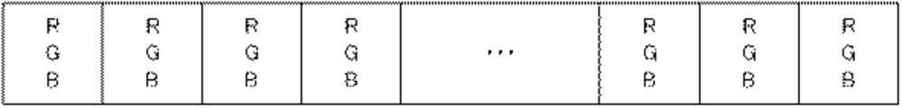
図8は、第3発光パターンの一例を示す図である。図8に示す第3発光パターンは、発光周波数が30[Hz]以下である。第3発光パターンは、赤、緑、青の何れかの発光が繰り返されるものである。 FIG. 8 is a diagram illustrating an example of the third light emission pattern. The third light emission pattern shown in FIG. 8 has a light emission frequency of 30 [Hz] or less. In the third light emission pattern, red, green, or blue light emission is repeated.
発光制御部126は、第3発光パターンの情報を駆動部112へ出力する。駆動部112は、発光制御部126からの第3発光パターンの情報に応じて、LED102が発する光の色相を時間的に変化させるための駆動信号を生成する。LED102は、駆動部112から出力される駆動信号に基づいて、第3発光パターンに応じて時間的に色相が変化する光を発する。
The light
次に、可視光通信システム1の動作を説明する。図9は、可視光通信システム1内のサーバ200による受信処理の動作の一例を示すフローチャートである。なお、以下において、サーバ200は、3種類の発光パターンが存在し、LED102が、移動機器100が停止中の場合には第1発光パターンで発光し、移動機器100が停止していないが速度α未満である場合には第2発光パターンで発光し、移動機器100の速度がα以上である場合には、第3発光パターンで発光することを認識しているものとする。
Next, the operation of the visible light communication system 1 will be described. FIG. 9 is a flowchart showing an example of an operation of reception processing by the
まず、制御部202内の撮影周期制御部236は、撮影部201が60[fps]の撮影周期で撮影を行うように制御する。撮影部201は、撮影周期制御部236の制御に応じて、60[fps]の撮影周期で撮影を行い、撮影毎にフレームを生成する(ステップS201)。
First, the imaging
画像処理部204は、撮影部201から出力されたフレーム(デジタルデータ)をそのまま制御部202へ出力する。制御部202内の移動検知部232は、画像処理部204からの複数のフレーム間の時間的な変化から周知の手法を用いてLED102の発光箇所を検出し、複数のフレーム間でのLED102の発光箇所の変化から周知の手法を用いて移動機器100の速度を検知する。更に、移動検知部232は、検知した移動機器100の速度に基づいて、移動機器100が停止しているか否かを判定する(ステップS202)。
The
移動機器100が停止していると判定された場合(ステップS202;YES)、撮影周期制御部236は、撮影部201が4[fps]の撮影周期で撮影を行うように制御する(ステップS203)。ここで撮影周期を4[fps]とするのは、LED102が第1発光パターン、すなわち発光周波数が2[Hz]以下で発光する場合の色の変化を全て検出可能とするためである。
When it is determined that the mobile device 100 is stopped (step S202; YES), the imaging
撮影部201は、撮影周期制御部236の制御に応じて、4[fps]の撮影周期で撮影を行い、撮影毎にフレームを生成する。画像処理部204は、撮影部201から出力されたフレームをそのまま制御部202へ出力する。制御部202内の情報取得部234は、移動機器100が停止していると判定されたことに基づいて、移動機器100内のLED102が第1発光パターンに応じた発光を行っているものと見なす。
The
次に、情報取得部234は、複数のフレーム内におけるLED102の発光箇所のうち、第1発光パターンのデータ部に対応する発光箇所を検出する。具体的には、情報取得部234は、発光箇所が黒となっているフレームをヘッダに対応するフレームと見なし、次以降の複数のフレームを第1発光パターンのデータ部に対応する発光箇所であると判定する。更に、情報取得部234は、複数のフレームにおける第1発光パターンのデータ部に対応する発光箇所の色の変化に基づいて、復号処理を行うことにより、元のデータ(送信対象のデータ)を取得する。更に、移動検知部232は、複数のフレーム内におけるLED102の発光箇所を、移動機器100の位置と見なして発光位置の捕捉を行う(ステップS204)。
Next, the
一方、移動機器100が停止していないと判定された場合(ステップS202;NO)、移動検知部232は、検知した移動機器100の速度がα未満であるか否かを判定する(ステップS205)。
On the other hand, when it is determined that the mobile device 100 is not stopped (step S202; NO), the
移動機器100の速度がα未満であると判定された場合(ステップS205;YES)、撮影周期制御部236は、撮影部201が20[fps]の撮影周期で撮影を行うように制御する(ステップS206)。ここで撮影周期を20[fps]とするのは、LED102が第2発光パターン、すなわち発光周波数が10[Hz]以下で発光する場合の色の変化を全て検出可能とするためである。
When it is determined that the speed of the mobile device 100 is less than α (step S205; YES), the imaging
撮影部201は、撮影周期制御部236の制御に応じて、20[fps]の撮影周期で撮影を行い、撮影毎にフレームを生成する。画像処理部204は、撮影部201から出力されたフレームをそのまま制御部202へ出力する。制御部202内の情報取得部234は、移動機器100の速度がα未満であると判定されたことに基づいて、移動機器100内のLED102が第2発光パターンに応じた発光を行っているものと見なす。
The
その後は、ステップS204と同様、情報取得部234は、複数のフレーム内におけるLED102の発光箇所のうち、第2発光パターンのデータ部に対応する発光箇所を検出する。具体的には、情報取得部234は、発光箇所が白である1つのフレーム、又は、発光箇所が赤となっている連続する3つのフレームをヘッダに対応するフレームと見なし、次以降の複数のフレームを第2発光パターンのデータ部に対応する発光箇所であると判定する。更に、情報取得部234は、複数のフレームにおける第2発光パターンのデータ部に対応する発光箇所の色の変化に基づいて、復号処理を行うことにより、元のデータ(送信対象のデータ)を取得する。更に、移動検知部232は、複数のフレーム内におけるLED102の発光箇所、特に、ヘッダに対応する発光箇所を、移動機器100の位置と見なして発光位置の捕捉を行う(ステップS207)。
Thereafter, as in step S204, the
一方、移動機器100の速度がα未満でないと判定された場合(ステップS205;NO)、撮影周期制御部236は、撮影部201が60[fps]の撮影周期を維持して撮影を行うように制御する(ステップS208)。ここで撮影周期を60[fps]とするのは、LED102が第3発光パターン、すなわち発光周波数が30[Hz]以下で発光する場合の色の変化を全て検出可能とするためである。
On the other hand, when it is determined that the speed of the mobile device 100 is not less than α (step S205; NO), the imaging
撮影部201は、撮影周期制御部236の制御に応じて、60[fps]の撮影周期で撮影を行い、撮影毎にフレームを生成する。画像処理部204は、撮影部201から出力されたフレームをそのまま制御部202へ出力する。制御部202内の情報取得部234は、移動機器100の速度がα未満でない、すなわち、移動機器100の速度がα以上であると判定されたことに基づいて、移動機器100内のLED102が第3発光パターンに応じた発光を行っているものと見なす。
The
次に、情報取得部234は、複数のフレーム内におけるLED102の発光箇所を、移動機器100の位置と見なして発光位置の捕捉を行う(ステップS209)。
Next, the
このように本実施形態では、移動機器100は自身の速度を検知し、移動機器100内のLED102は、移動機器100の速度が速いほど発光周期が短くなるように第1発光パターン、第2発光パターン及び第3発光パターンの何れかに応じた発光を行う。一方、サーバ200は、撮影部201の撮影により得られたフレームから移動機器100の速度を検知し、速度が遅いほど撮影周期が長くなるように撮影部201の撮影周期を制御する。このように、移動機器100の速度が遅いほど、移動機器100内のLED102の発光周期が長くなり、サーバ200内の撮影部201の撮影周期が長くなるようにすることで、発光及び撮影による処理負担の軽減、例えば消費電力の軽減を図ることができる。一方、移動機器100の速度が速いほど、移動機器100内のLED102の発光周期が短くなり、サーバ200内の撮影部201の撮影周期が短くなるようにすることで、移動機器100の速度が速い場合であっても、サーバ200が移動機器100の発光位置の捕捉を安定的に行うことが可能となる。
Thus, in this embodiment, the mobile device 100 detects its own speed, and the
また、移動機器100が停止している場合には、サーバ200における発光位置の捕捉が容易であるために、移動機器100における送信対象のデータの送信のために用いられる第1発光パターンをサーバ200における移動機器100の発光位置の捕捉にも用いるようにし、移動機器100の速度がα以上である場合には、サーバ200における移動機器100の発光位置の捕捉が困難であるために、発光位置の捕捉専用の第3発光パターンが用いられる。これにより、情報の伝送を効率よく行うとともに、サーバ200が移動機器100の発光位置の捕捉を安定的に行うことが可能となる。
Further, when the mobile device 100 is stopped, it is easy to capture the light emission position in the
また、移動機器100の速度がα未満である場合には、移動機器100における送信対象のデータの送信及びサーバ200における移動機器100の発光位置の捕捉のための第2発光パターンが用いられる。第2発光パターンは、図6に示すように第1発光パターンにおけるヘッダの黒を白に置き換えたものであり、あるいは、図7に示すように第1発光パターンにおけるヘッダの黒を3つの赤に置き換えたものである。このため、サーバ200がヘッダにおける発光を移動機器100の発光位置の捕捉に用いることで、発光位置の捕捉を容易に行うことができる。
When the speed of the mobile device 100 is less than α, the second light emission pattern for transmitting the transmission target data in the mobile device 100 and capturing the light emission position of the mobile device 100 in the
なお、本発明は、上記実施形態の説明及び図面によって限定されるものではなく、上記実施形態及び図面に適宜変更等を加えることは可能である。 Note that the present invention is not limited by the description of the above-described embodiment and the drawings, and appropriate modifications and the like can be made to the above-described embodiment and the drawings.
例えば、上述した実施形態では、サーバ200において、制御部202内の移動検知部232は、画像処理部204からの複数のフレーム間の時間的な変化から周知の手法を用いてLED102の発光箇所を検出し、複数のフレーム間でのLED102の発光箇所の変化から周知の手法を用いて移動機器100の速度を検知するようにした。しかし、移動機器100の速度の検知は、これに制限されず、何らかの通信方法を用いて、移動機器100からサーバ200へ速度の情報が通知されるようにしてもよい。例えば、発光パターンのデータ部に速度の情報が割り当てられるようにし、移動機器100内のLED102が、データ部に速度の情報が割り当てられた発光パターンに応じた発光を行うようにし、サーバ200が、データ部に対応する発光箇所の色の変化に基づいて、復号処理を行うことにより、移動機器100の速度を取得するようにしてもよい。また、移動機器100が停止した場合には、移動機器100内のLED102が、データ部に停止したことを示す情報が割り当てられた発光パターンに応じた発光を行うようにし、サーバ200が、データ部に対応する発光箇所の色の変化に基づいて、復号処理を行うことにより、移動機器100が停止したことを認識するようにしてもよい。
For example, in the embodiment described above, in the
また、上述した実施形態では、可視光である赤、緑、青の光を通信に用いる場合について説明したが、他の色の可視光を用いてもよく、更には、赤外線等の可視光以外の光を用いてもよい。また、第1発光パターン、第2発光パターン及び第3発光パターンの発光の構成は他の発光パターンの発光の構成でもよく、更には、何れかの発光パターンの組み合わせとしてもよく、組み合わせた発光パターンの時間的な順番の組み合わせによるものであってもよい。また、発光パターンは色相が時間的に変化するものに限定されず、輝度(明度)や彩度が時間的に変化するものであってもよい。また、移動機器100が移動中である場合には、LED102の輝度を向上させてもよい。これにより、サーバ200における発光位置の捕捉がしやすくなる。
In the above-described embodiment, the case of using visible light of red, green, and blue for communication has been described. However, visible light of other colors may be used, and further, other than visible light such as infrared rays. May be used. In addition, the light emission configuration of the first light emission pattern, the second light emission pattern, and the third light emission pattern may be a light emission configuration of another light emission pattern, or may be a combination of any one of the light emission patterns. It may be based on a combination of time order. Further, the light emission pattern is not limited to the one whose hue changes with time, and the luminance (brightness) and saturation may change with time. Further, when the mobile device 100 is moving, the brightness of the
また、上記実施形態では、第1発光パターン〜第3発光パターンの長さ(繰り返し周期)については特に限定していないが、移動機器100の速度が速いほど長い発光パターンが用いられるようにしてもよい。これにより、サーバ200における発光位置の捕捉がしやすくなる。また、移動機器100が停止した場合、あるいは、一定期間停止した場合には、LED102は、発光を停止するようにし、サーバ200に発光を停止する旨を、他の通信システムで通知して撮影部201を省電力モードに移行させるようにしてもよく、発光を再開する場合には、上記と同様にサーバ200へ発光を再開する旨を通知して撮影部201を通常の動作モードに移行させるようにしてもよい。これにより、移動機器100が停止しておりサーバ200における発光位置の捕捉が不要である場合に、発光位置の捕捉のための不要な発光が行われないようにして、発光による処理負担の軽減を図ることができる。また、受光(撮像)することによる処理負担の軽減を図ることができる。
Moreover, in the said embodiment, although it does not specifically limit about the length (repetition period) of a 1st light emission pattern-a 3rd light emission pattern, You may make it use a long light emission pattern, so that the speed of the mobile device 100 is quick. Good. Thereby, it becomes easy to capture the light emission position in the
また、移動機器100内の光源はLEDに限定されない。例えば、表示装置を構成するLCD、PDP、ELディスプレイ等の一部に光源が構成されていてもよい。 Further, the light source in the mobile device 100 is not limited to the LED. For example, a light source may be configured in a part of an LCD, PDP, EL display, or the like that constitutes the display device.
また、サーバ200は、撮影部が設けられて撮影が可能であれば、どのような装置でもよい。
Further, the
また、上記実施形態において、実行されるプログラムは、フレキシブルディスク、CD−ROM(Compact Disc Read - Only Memory)、DVD(Digital Versatile Disc)、MO(Magneto - Optical Disc)等のコンピュータで読み取り可能な記録媒体に格納して配布し、そのプログラムをインストールすることにより、上述の処理を実行するシステムを構成することとしてもよい。 In the above embodiment, the program to be executed is a computer-readable recording such as a flexible disk, a CD-ROM (Compact Disc Read-Only Memory), a DVD (Digital Versatile Disc), and an MO (Magneto-Optical Disc). A system that executes the above-described processing may be configured by storing and distributing the program on a medium and installing the program.
また、プログラムをインターネット等のネットワーク上の所定のサーバが有するディスク装置等に格納しておき、例えば、搬送波に重畳させて、ダウンロード等するようにしてもよい。 Further, the program may be stored in a disk device or the like of a predetermined server on a network such as the Internet, and may be downloaded, for example, superimposed on a carrier wave.
なお、上述の機能を、OS(Operating System)が分担して実現する場合又はOSとアプリケーションとの協働により実現する場合等には、OS以外の部分のみを媒体に格納して配布してもよく、また、ダウンロード等してもよい。 Note that when the above functions are realized by sharing an OS (Operating System) or when the functions are realized by cooperation between the OS and an application, only the part other than the OS may be stored in a medium and distributed. You may also download it.
以上、本発明の好ましい実施形態について説明したが、本発明は係る特定の実施形態に限定されるものではなく、本発明には、特許請求の範囲に記載された発明とその均等の範囲が含まれる。以下に、本願出願の当初の特許請求の範囲に記載された発明を付記する。 As mentioned above, although preferable embodiment of this invention was described, this invention is not limited to the specific embodiment which concerns, This invention includes the invention described in the claim, and its equivalent range It is. Hereinafter, the invention described in the scope of claims of the present application will be appended.
(付記1)
光を通信媒体として任意の情報を外部の撮像装置へ送信する発光装置であって、
発光手段と、
前記発光手段の移動を検知する移動検知手段と、
前記移動検知手段の検知結果に応じて、前記撮像装置による前記任意の情報の受信のための発光位置の捕捉が可能となるように、前記発光手段の発光態様を変更する発光制御手段と、
を備えることを特徴とする発光装置。
(Appendix 1)
A light emitting device that transmits arbitrary information to an external imaging device using light as a communication medium,
A light emitting means;
Movement detecting means for detecting movement of the light emitting means;
A light emission control unit that changes a light emission mode of the light emitting unit so that a light emission position for receiving the arbitrary information can be captured by the imaging device according to a detection result of the movement detection unit;
A light emitting device comprising:
(付記2)
前記発光制御手段は、前記移動検知手段による前記発光手段の移動を検知しない場合に、前記任意の情報を所定の発光パターンで発光するように前記発光手段の発光態様を変更することを特徴とする付記1に記載の発光装置。
(Appendix 2)
The light emission control means changes the light emission mode of the light emission means so that the arbitrary information is emitted in a predetermined light emission pattern when the movement detection means does not detect the movement of the light emission means. The light-emitting device according to attachment 1.
(付記3)
前記移動検知手段により前記発光手段の移動を検知した場合、その移動速度が所定速度以上か未満かを判断する移動速度判断手段を更に備え、
前記発光制御手段は、前記移動速度判断手段により前記発光手段の移動速度が所定速度以上であると判断された場合に、前記発光位置の捕捉が可能となる発光パターンで発光するように前記発光手段の発光態様を変更することを特徴とする付記1又は2に記載の発光装置。
(Appendix 3)
When the movement detecting means detects the movement of the light emitting means, the apparatus further comprises a moving speed determining means for determining whether the moving speed is equal to or higher than a predetermined speed.
The light emission control unit is configured to emit light in a light emission pattern that enables capturing of the light emission position when the movement speed determination unit determines that the movement speed of the light emission unit is equal to or higher than a predetermined speed. The light-emitting device according to appendix 1 or 2, wherein the light-emission mode is changed.
(付記4)
前記発光制御手段は、前記移動速度判断手段により前記発光手段の移動速度が所定速度未満であると判断された場合に、所定の発光パターンと前記発光位置の捕捉が可能となる発光パターンとを含む発光パターンで発光するように前記発光手段の発光態様を変更することを特徴とする付記3に記載の発光装置。
(Appendix 4)
The light emission control means includes a predetermined light emission pattern and a light emission pattern capable of capturing the light emission position when the movement speed determination means determines that the movement speed of the light emission means is less than a predetermined speed. The light-emitting device according to appendix 3, wherein the light-emitting mode of the light-emitting means is changed so as to emit light in a light-emitting pattern.
(付記5)
前記所定の発光パターンには、前記発光手段に発光させない非発光の期間が含まれ、
前記発光制御手段は、前記移動速度判断手段により前記発光手段の移動速度が所定速度未満であると判断された場合に、前記所定の発光パターンにおける前記非発光の期間を発光する期間に置き換えるように前記発光手段の発光態様を変更することを特徴とする付記4に記載の発光装置。
(Appendix 5)
The predetermined light emission pattern includes a non-light emission period during which the light emitting means does not emit light,
The light emission control means replaces the non-light emission period in the predetermined light emission pattern with a light emission period when the movement speed determination means determines that the movement speed of the light emission means is less than a predetermined speed. The light-emitting device according to appendix 4, wherein the light-emitting mode of the light-emitting means is changed.
(付記6)
前記所定の発光パターンには、前記発光手段に発光させない非発光の期間が含まれ、
前記発光制御手段は、前記移動速度判断手段により前記発光手段の移動速度が所定速度未満であると判断された場合に、前記所定の発光パターンにおける前記非発光の期間を所定の色で発光する期間に置き換えるように前記発光手段の発光態様を変更することを特徴とする付記4に記載の発光装置。
(Appendix 6)
The predetermined light emission pattern includes a non-light emission period during which the light emitting means does not emit light,
The light emission control means is a period in which the non-light emission period in the predetermined light emission pattern is emitted in a predetermined color when the movement speed determination means determines that the movement speed of the light emission means is less than a predetermined speed. The light-emitting device according to appendix 4, wherein the light-emitting mode of the light-emitting means is changed so as to replace
(付記7)
前記発光態様には所定の発光パターンの発光周期が含まれ、
前記発光制御手段は、前記移動速度判断手段が判断する際に取得した移動速度に応じて、前記所定の発光パターンの発光周期を変更することを特徴とする付記3〜6の何れか1つに記載の発光装置。
(Appendix 7)
The light emission mode includes a light emission period of a predetermined light emission pattern,
The light emission control means changes the light emission cycle of the predetermined light emission pattern according to the movement speed acquired when the movement speed judgment means judges. The light-emitting device of description.
(付記8)
前記発光制御手段は、前記移動速度判断手段が判断する際に取得した移動速度が速くなるほど、前記所定の発光パターンの発光周期を短くすることを特徴とする付記7に記載の発光装置。
(Appendix 8)
The light emitting device according to appendix 7, wherein the light emission control means shortens the light emission cycle of the predetermined light emission pattern as the movement speed acquired when the movement speed judgment means judges becomes faster.
(付記9)
所定の撮影周期で撮像するとともに光を通信媒体として任意の情報を送信する発光装置からの光を受信する撮像装置であって、
撮影手段と、
前記撮影手段により撮影された画像に含まれる前記発光装置からの光の像から前記任意の情報を取得する情報取得手段と、
前記所定の撮影周期の撮影により取得された複数の画像から前記光の像の移動を検知する移動検知手段と、
前記移動検知手段の検知結果に応じて、前記所定の撮影周期を変更する撮影周期制御手段と、
を備えることを特徴とする撮像装置。
(Appendix 9)
An imaging device that receives light from a light emitting device that picks up an image at a predetermined shooting period and transmits arbitrary information using light as a communication medium,
Photographing means;
Information acquisition means for acquiring the arbitrary information from an image of light from the light emitting device included in the image captured by the imaging means;
Movement detecting means for detecting movement of the image of the light from a plurality of images acquired by shooting at the predetermined shooting period;
An imaging cycle control unit that changes the predetermined imaging cycle according to a detection result of the movement detection unit;
An imaging apparatus comprising:
(付記10)
発光装置と撮像装置との間で、光を通信媒体として任意の情報を伝送する情報伝送システムであって、
前記発光装置は、
発光手段と、
前記発光手段の移動を検知する第1の移動検知手段と、
前記第1の移動検知手段の検知結果に応じて、前記撮像装置による前記任意の情報の受信のための発光位置の捕捉が可能となるように、前記発光手段の発光態様を変更する発光制御手段と、
を備えることを特徴とする情報伝送システム。
(Appendix 10)
An information transmission system that transmits arbitrary information using light as a communication medium between a light emitting device and an imaging device,
The light emitting device
A light emitting means;
First movement detecting means for detecting movement of the light emitting means;
Light emission control means for changing the light emission mode of the light emitting means so that the light emitting position for receiving the arbitrary information can be captured by the imaging device according to the detection result of the first movement detecting means. When,
An information transmission system comprising:
(付記11)
前記撮像装置は、
撮影手段と、
前記撮影手段により撮影された画像に含まれる前記発光装置からの光の像から前記任意の情報を取得する情報取得手段と、
所定の撮影周期の撮影により取得された複数の画像から前記光の像の移動を検知する第2の移動検知手段と、
前記第2の移動検知手段の検知結果に応じて、前記所定の撮影周期を変更する撮影周期制御手段と、
を備えることを特徴とする付記10に記載の情報伝送システム。
(Appendix 11)
The imaging device
Photographing means;
Information acquisition means for acquiring the arbitrary information from an image of light from the light emitting device included in the image captured by the imaging means;
Second movement detection means for detecting movement of the light image from a plurality of images acquired by imaging at a predetermined imaging cycle;
An imaging cycle control unit that changes the predetermined imaging cycle according to a detection result of the second movement detection unit;
The information transmission system according to appendix 10, characterized by comprising:
(付記12)
前記撮像装置は、
前記第2の移動検知手段により移動が検知された場合に、前記光の像の移動速度を取得する移動速度取得手段を更に備え、
前記撮影周期制御手段は、前記移動速度取得手段により取得された前記光の像の移動速度に基づいて、前記所定の撮影周期を変更することを特徴とする付記11に記載の情報伝送システム。
(Appendix 12)
The imaging device
A movement speed acquisition means for acquiring a movement speed of the image of the light when movement is detected by the second movement detection means;
12. The information transmission system according to appendix 11, wherein the imaging cycle control unit changes the predetermined imaging cycle based on a moving speed of the light image acquired by the moving speed acquisition unit.
(付記13)
発光装置と撮像装置との間で、光を通信媒体として任意の情報を伝送する情報伝送システムにおける情報伝送方法であって、
前記発光装置が発光部の移動を検知する移動検知ステップと、
前記発光装置が前記移動検知ステップでの検知結果に応じて、前記撮像装置による前記任意の情報の受信のための発光位置の捕捉が可能となるように、前記発光部の発光態様を変更する発光制御ステップと、
を含むことを特徴とする情報伝送方法。
(Appendix 13)
An information transmission method in an information transmission system for transmitting arbitrary information using light as a communication medium between a light emitting device and an imaging device,
A movement detecting step in which the light emitting device detects movement of the light emitting unit;
Light emission that changes the light emission mode of the light emitting unit so that the light emitting device can capture the light emission position for receiving the arbitrary information by the imaging device according to the detection result in the movement detection step. Control steps;
An information transmission method comprising:
(付記14)
外部の撮像装置へ光を通信媒体として任意の情報を送信する発光装置が備えるコンピュータを、
発光部の移動を検知する移動検知手段、
前記移動検知手段の検知結果に応じて、前記撮像装置による前記任意の情報の受信のための発光位置の捕捉が可能となるように、前記発光部の発光態様を変更する発光制御手段、
として機能させることを特徴とするプログラム。
(Appendix 14)
A computer provided in a light emitting device that transmits arbitrary information using light as a communication medium to an external imaging device,
A movement detecting means for detecting movement of the light emitting unit;
A light emission control unit that changes a light emission mode of the light emitting unit so that a light emission position for receiving the arbitrary information can be captured by the imaging device according to a detection result of the movement detection unit.
A program characterized by functioning as
(付記15)
撮影部にて所定の撮影周期で撮像するとともに、光を通信媒体として任意の情報を送信する発光装置からの光を受光する撮像装置が備えるコンピュータを、
前記撮影部により撮影された画像に含まれる前記発光装置からの光の像から前記任意の情報を取得する情報取得手段、
前記所定の撮影周期の撮影により取得された複数の画像から前記光の像の移動を検知する移動検知手段、
前記移動検知手段の検知結果に応じて、前記所定の撮影周期を変更する撮影周期制御手段、
として機能させることを特徴とするプログラム。
(Appendix 15)
A computer provided with an imaging device that receives light from a light emitting device that transmits arbitrary information using light as a communication medium while capturing an image at a photographing unit in a photographing unit,
Information acquisition means for acquiring the arbitrary information from an image of light from the light emitting device included in the image captured by the imaging unit;
A movement detecting means for detecting movement of the image of the light from a plurality of images acquired by shooting at the predetermined shooting period;
An imaging cycle control unit that changes the predetermined imaging cycle according to a detection result of the movement detection unit,
A program characterized by functioning as
1…可視光通信システム、100、100a、100b、100c…移動機器、102、102a、102b、102c…LED、103、202…制御部、104、205…メモリ、107…速度センサ、108、208…通信部、112…駆動部、122…移動制御部、124、232…移動検知部、126…発光制御部、128…移動部、200…サーバ、201…撮影部、203…レンズ、204…画像処理部、206…操作部、207…表示部、234…情報取得部、236…撮影周期制御部
DESCRIPTION OF SYMBOLS 1 ... Visible light communication system, 100, 100a, 100b, 100c ... Mobile equipment, 102, 102a, 102b, 102c ... LED, 103, 202 ... Control part, 104, 205 ... Memory, 107 ... Speed sensor, 108, 208 ...
Claims (15)
発光手段と、
前記発光手段の移動を検知する移動検知手段と、
前記移動検知手段の検知結果に応じて、前記撮像装置による前記任意の情報の受信のための発光位置の捕捉が可能となるように、前記発光手段の発光態様を変更する発光制御手段と、
を備えることを特徴とする発光装置。 A light emitting device that transmits arbitrary information to an external imaging device using light as a communication medium,
A light emitting means;
Movement detecting means for detecting movement of the light emitting means;
A light emission control unit that changes a light emission mode of the light emitting unit so that a light emission position for receiving the arbitrary information can be captured by the imaging device according to a detection result of the movement detection unit;
A light emitting device comprising:
前記発光制御手段は、前記移動速度判断手段により前記発光手段の移動速度が所定速度以上であると判断された場合に、前記発光位置の捕捉が可能となる発光パターンで発光するように前記発光手段の発光態様を変更することを特徴とする請求項1又は2に記載の発光装置。 When the movement detecting means detects the movement of the light emitting means, the apparatus further comprises a moving speed determining means for determining whether the moving speed is equal to or higher than a predetermined speed.
The light emission control unit is configured to emit light in a light emission pattern that enables capturing of the light emission position when the movement speed determination unit determines that the movement speed of the light emission unit is equal to or higher than a predetermined speed. The light emitting device according to claim 1, wherein the light emitting mode is changed.
前記発光制御手段は、前記移動速度判断手段により前記発光手段の移動速度が所定速度未満であると判断された場合に、前記所定の発光パターンにおける前記非発光の期間を発光する期間に置き換えるように前記発光手段の発光態様を変更することを特徴とする請求項4に記載の発光装置。 The predetermined light emission pattern includes a non-light emission period during which the light emitting means does not emit light,
The light emission control means replaces the non-light emission period in the predetermined light emission pattern with a light emission period when the movement speed determination means determines that the movement speed of the light emission means is less than a predetermined speed. The light emitting device according to claim 4, wherein a light emitting mode of the light emitting unit is changed.
前記発光制御手段は、前記移動速度判断手段により前記発光手段の移動速度が所定速度未満であると判断された場合に、前記所定の発光パターンにおける前記非発光の期間を所定の色で発光する期間に置き換えるように前記発光手段の発光態様を変更することを特徴とする請求項4に記載の発光装置。 The predetermined light emission pattern includes a non-light emission period during which the light emitting means does not emit light,
The light emission control means is a period in which the non-light emission period in the predetermined light emission pattern is emitted in a predetermined color when the movement speed determination means determines that the movement speed of the light emission means is less than a predetermined speed. The light-emitting device according to claim 4, wherein the light-emitting mode of the light-emitting means is changed to replace
前記発光制御手段は、前記移動速度判断手段が判断する際に取得した移動速度に応じて、前記所定の発光パターンの発光周期を変更することを特徴とする請求項3〜6の何れか1項に記載の発光装置。 The light emission mode includes a light emission period of a predetermined light emission pattern,
The light emission control means changes the light emission cycle of the predetermined light emission pattern according to the movement speed acquired when the movement speed judgment means judges. The light emitting device according to 1.
撮影手段と、
前記撮影手段により撮影された画像に含まれる前記発光装置からの光の像から前記任意の情報を取得する情報取得手段と、
前記所定の撮影周期の撮影により取得された複数の画像から前記光の像の移動を検知する移動検知手段と、
前記移動検知手段の検知結果に応じて、前記所定の撮影周期を変更する撮影周期制御手段と、
を備えることを特徴とする撮像装置。 An imaging device that receives light from a light emitting device that picks up an image at a predetermined shooting period and transmits arbitrary information using light as a communication medium,
Photographing means;
Information acquisition means for acquiring the arbitrary information from an image of light from the light emitting device included in the image captured by the imaging means;
Movement detecting means for detecting movement of the image of the light from a plurality of images acquired by shooting at the predetermined shooting period;
An imaging cycle control unit that changes the predetermined imaging cycle according to a detection result of the movement detection unit;
An imaging apparatus comprising:
前記発光装置は、
発光手段と、
前記発光手段の移動を検知する第1の移動検知手段と、
前記第1の移動検知手段の検知結果に応じて、前記撮像装置による前記任意の情報の受信のための発光位置の捕捉が可能となるように、前記発光手段の発光態様を変更する発光制御手段と、
を備えることを特徴とする情報伝送システム。 An information transmission system that transmits arbitrary information using light as a communication medium between a light emitting device and an imaging device,
The light emitting device
A light emitting means;
First movement detecting means for detecting movement of the light emitting means;
Light emission control means for changing the light emission mode of the light emitting means so that the light emitting position for receiving the arbitrary information can be captured by the imaging device according to the detection result of the first movement detecting means. When,
An information transmission system comprising:
撮影手段と、
前記撮影手段により撮影された画像に含まれる前記発光装置からの光の像から前記任意の情報を取得する情報取得手段と、
所定の撮影周期の撮影により取得された複数の画像から前記光の像の移動を検知する第2の移動検知手段と、
前記第2の移動検知手段の検知結果に応じて、前記所定の撮影周期を変更する撮影周期制御手段と、
を備えることを特徴とする請求項10に記載の情報伝送システム。 The imaging device
Photographing means;
Information acquisition means for acquiring the arbitrary information from an image of light from the light emitting device included in the image captured by the imaging means;
Second movement detection means for detecting movement of the light image from a plurality of images acquired by imaging at a predetermined imaging cycle;
An imaging cycle control unit that changes the predetermined imaging cycle according to a detection result of the second movement detection unit;
The information transmission system according to claim 10, further comprising:
前記第2の移動検知手段により移動が検知された場合に、前記光の像の移動速度を取得する移動速度取得手段を更に備え、
前記撮影周期制御手段は、前記移動速度取得手段により取得された前記光の像の移動速度に基づいて、前記所定の撮影周期を変更することを特徴とする請求項11に記載の情報伝送システム。 The imaging device
A movement speed acquisition means for acquiring a movement speed of the image of the light when movement is detected by the second movement detection means;
12. The information transmission system according to claim 11, wherein the imaging cycle control unit changes the predetermined imaging cycle based on a moving speed of the light image acquired by the moving speed acquisition unit.
前記発光装置が発光部の移動を検知する移動検知ステップと、
前記発光装置が前記移動検知ステップでの検知結果に応じて、前記撮像装置による前記任意の情報の受信のための発光位置の捕捉が可能となるように、前記発光部の発光態様を変更する発光制御ステップと、
を含むことを特徴とする情報伝送方法。 An information transmission method in an information transmission system for transmitting arbitrary information using light as a communication medium between a light emitting device and an imaging device,
A movement detecting step in which the light emitting device detects movement of the light emitting unit;
Light emission that changes the light emission mode of the light emitting unit so that the light emitting device can capture the light emission position for receiving the arbitrary information by the imaging device according to the detection result in the movement detection step. Control steps;
An information transmission method comprising:
発光部の移動を検知する移動検知手段、
前記移動検知手段の検知結果に応じて、前記撮像装置による前記任意の情報の受信のための発光位置の捕捉が可能となるように、前記発光部の発光態様を変更する発光制御手段、
として機能させることを特徴とするプログラム。 A computer provided in a light emitting device that transmits arbitrary information using light as a communication medium to an external imaging device,
A movement detecting means for detecting movement of the light emitting unit;
A light emission control unit that changes a light emission mode of the light emitting unit so that a light emission position for receiving the arbitrary information can be captured by the imaging device according to a detection result of the movement detection unit.
A program characterized by functioning as
前記撮影部により撮影された画像に含まれる前記発光装置からの光の像から前記任意の情報を取得する情報取得手段、
前記所定の撮影周期の撮影により取得された複数の画像から前記光の像の移動を検知する移動検知手段、
前記移動検知手段の検知結果に応じて、前記所定の撮影周期を変更する撮影周期制御手段、
として機能させることを特徴とするプログラム。 A computer provided with an imaging device that receives light from a light emitting device that transmits arbitrary information using light as a communication medium while capturing an image at a photographing unit in a photographing unit,
Information acquisition means for acquiring the arbitrary information from an image of light from the light emitting device included in the image captured by the imaging unit;
A movement detecting means for detecting movement of the image of the light from a plurality of images acquired by shooting at the predetermined shooting period;
An imaging cycle control unit that changes the predetermined imaging cycle according to a detection result of the movement detection unit,
A program characterized by functioning as
Priority Applications (3)
| Application Number | Priority Date | Filing Date | Title |
|---|---|---|---|
| JP2017003085A JP2018113600A (en) | 2017-01-12 | 2017-01-12 | Light emitting device, imaging device, information transmission system, information transmission method, and program |
| US15/852,894 US10326534B2 (en) | 2017-01-12 | 2017-12-22 | Light-emitting apparatus, imaging apparatus, information transmission system and information transmission method |
| CN201810028661.3A CN108306682B (en) | 2017-01-12 | 2018-01-11 | Light emitting device, information transmission system, and information transmission method |
Applications Claiming Priority (1)
| Application Number | Priority Date | Filing Date | Title |
|---|---|---|---|
| JP2017003085A JP2018113600A (en) | 2017-01-12 | 2017-01-12 | Light emitting device, imaging device, information transmission system, information transmission method, and program |
Publications (2)
| Publication Number | Publication Date |
|---|---|
| JP2018113600A true JP2018113600A (en) | 2018-07-19 |
| JP2018113600A5 JP2018113600A5 (en) | 2019-03-28 |
Family
ID=62783659
Family Applications (1)
| Application Number | Title | Priority Date | Filing Date |
|---|---|---|---|
| JP2017003085A Pending JP2018113600A (en) | 2017-01-12 | 2017-01-12 | Light emitting device, imaging device, information transmission system, information transmission method, and program |
Country Status (3)
| Country | Link |
|---|---|
| US (1) | US10326534B2 (en) |
| JP (1) | JP2018113600A (en) |
| CN (1) | CN108306682B (en) |
Cited By (1)
| Publication number | Priority date | Publication date | Assignee | Title |
|---|---|---|---|---|
| JP2021148712A (en) * | 2020-03-23 | 2021-09-27 | カシオ計算機株式会社 | Position measuring system, position measuring device, position measuring method, and program |
Families Citing this family (1)
| Publication number | Priority date | Publication date | Assignee | Title |
|---|---|---|---|---|
| JP7052696B2 (en) * | 2018-11-30 | 2022-04-12 | カシオ計算機株式会社 | Transmitter, transmission method and program |
Citations (10)
| Publication number | Priority date | Publication date | Assignee | Title |
|---|---|---|---|---|
| JPH10200477A (en) * | 1997-01-14 | 1998-07-31 | Mitsubishi Electric Corp | Optical transmitter-receiver |
| JP2006287921A (en) * | 2005-03-09 | 2006-10-19 | Fuji Photo Film Co Ltd | Moving image generating apparatus, moving image generation method, and program |
| JP2007272511A (en) * | 2006-03-31 | 2007-10-18 | Casio Comput Co Ltd | Information transmission system, imaging device, information output method, and information output program |
| JP2008148064A (en) * | 2006-12-11 | 2008-06-26 | Seiko Epson Corp | Vehicle control value determining device, imaging apparatus, imaging and reproduction system, vehicle control value determining method, and imaging method |
| JP2008219428A (en) * | 2007-03-02 | 2008-09-18 | Fujifilm Corp | Imaging apparatus |
| JP2012043302A (en) * | 2010-08-20 | 2012-03-01 | Toshiba Corp | Visible light information processor, visible light information processing method and program thereof |
| JP2013219814A (en) * | 2009-09-19 | 2013-10-24 | Samsung Electronics Co Ltd | Apparatus and method for supporting mobility of mobile terminal that performs visible light communication |
| JP2013236363A (en) * | 2012-04-13 | 2013-11-21 | Casio Comput Co Ltd | Display device and program |
| JP2015177262A (en) * | 2014-03-13 | 2015-10-05 | カシオ計算機株式会社 | Imaging apparatus, subject tracking method, and program |
| JP2016124332A (en) * | 2014-12-26 | 2016-07-11 | 司 小笠原 | Safety confirmation lamp system |
Family Cites Families (10)
| Publication number | Priority date | Publication date | Assignee | Title |
|---|---|---|---|---|
| JP2002010243A (en) | 2000-06-16 | 2002-01-11 | Mitsubishi Heavy Ind Ltd | Moving picture processing camera |
| CN1878034B (en) * | 2006-05-26 | 2010-04-21 | 上海大学 | Radio optical communication system for rectilinear motion objects |
| JP5199171B2 (en) * | 2009-04-17 | 2013-05-15 | 株式会社ジャパンディスプレイイースト | Display device |
| CN102577180B (en) * | 2009-09-18 | 2016-03-30 | 交互数字专利控股公司 | Visible light communication (VLC) is carried out to the method and apparatus of the light modulation of speed control |
| JP5648866B2 (en) | 2012-10-02 | 2015-01-07 | カシオ計算機株式会社 | Imaging system, imaging method, imaging apparatus, and program |
| CN103259592B (en) * | 2013-05-24 | 2016-05-11 | 江苏大学 | A kind of visible light communication net and WLAN fusion method |
| JP6194702B2 (en) * | 2013-08-30 | 2017-09-13 | ソニー株式会社 | EXPOSURE CONTROL DEVICE, EXPOSURE CONTROL METHOD, AND IMAGING DEVICE |
| CN103475409B (en) * | 2013-09-05 | 2016-05-25 | 江苏大学 | Moving vehicle visible ray radio communication receives switching method and apparatus |
| JP6459620B2 (en) | 2015-02-24 | 2019-01-30 | カシオ計算機株式会社 | Light receiving unit, light emission control method and program |
| WO2016189591A1 (en) * | 2015-05-22 | 2016-12-01 | オリンパス株式会社 | Scanning endoscope and control method therefor |
-
2017
- 2017-01-12 JP JP2017003085A patent/JP2018113600A/en active Pending
- 2017-12-22 US US15/852,894 patent/US10326534B2/en active Active
-
2018
- 2018-01-11 CN CN201810028661.3A patent/CN108306682B/en active Active
Patent Citations (10)
| Publication number | Priority date | Publication date | Assignee | Title |
|---|---|---|---|---|
| JPH10200477A (en) * | 1997-01-14 | 1998-07-31 | Mitsubishi Electric Corp | Optical transmitter-receiver |
| JP2006287921A (en) * | 2005-03-09 | 2006-10-19 | Fuji Photo Film Co Ltd | Moving image generating apparatus, moving image generation method, and program |
| JP2007272511A (en) * | 2006-03-31 | 2007-10-18 | Casio Comput Co Ltd | Information transmission system, imaging device, information output method, and information output program |
| JP2008148064A (en) * | 2006-12-11 | 2008-06-26 | Seiko Epson Corp | Vehicle control value determining device, imaging apparatus, imaging and reproduction system, vehicle control value determining method, and imaging method |
| JP2008219428A (en) * | 2007-03-02 | 2008-09-18 | Fujifilm Corp | Imaging apparatus |
| JP2013219814A (en) * | 2009-09-19 | 2013-10-24 | Samsung Electronics Co Ltd | Apparatus and method for supporting mobility of mobile terminal that performs visible light communication |
| JP2012043302A (en) * | 2010-08-20 | 2012-03-01 | Toshiba Corp | Visible light information processor, visible light information processing method and program thereof |
| JP2013236363A (en) * | 2012-04-13 | 2013-11-21 | Casio Comput Co Ltd | Display device and program |
| JP2015177262A (en) * | 2014-03-13 | 2015-10-05 | カシオ計算機株式会社 | Imaging apparatus, subject tracking method, and program |
| JP2016124332A (en) * | 2014-12-26 | 2016-07-11 | 司 小笠原 | Safety confirmation lamp system |
Cited By (3)
| Publication number | Priority date | Publication date | Assignee | Title |
|---|---|---|---|---|
| JP2021148712A (en) * | 2020-03-23 | 2021-09-27 | カシオ計算機株式会社 | Position measuring system, position measuring device, position measuring method, and program |
| JP7006714B2 (en) | 2020-03-23 | 2022-01-24 | カシオ計算機株式会社 | Positioning system, position measuring device, position measuring method and program |
| US11783497B2 (en) | 2020-03-23 | 2023-10-10 | Casio Computer Co., Ltd. | Position measuring device, position measuring method, and recording medium |
Also Published As
| Publication number | Publication date |
|---|---|
| US10326534B2 (en) | 2019-06-18 |
| CN108306682A (en) | 2018-07-20 |
| US20180198532A1 (en) | 2018-07-12 |
| CN108306682B (en) | 2021-06-08 |
Similar Documents
| Publication | Publication Date | Title |
|---|---|---|
| JP5973704B2 (en) | Projection control apparatus and projection control method | |
| JP2018113600A (en) | Light emitting device, imaging device, information transmission system, information transmission method, and program | |
| US10951313B2 (en) | Transmitting device, transmission method, and recording medium | |
| JP2013009072A5 (en) | Information transmission system, information transmission device, information reception device, information transmission method, information transmission method, information reception method, and program | |
| US9729794B2 (en) | Display device, display control method, and non-transitory recording medium | |
| JP6459620B2 (en) | Light receiving unit, light emission control method and program | |
| CN108668089B (en) | Information processing apparatus, information processing method, and recording medium | |
| US9843387B2 (en) | Decoding apparatus, decoding method, and non-transitory recording medium | |
| JP2018121169A (en) | Light-emitting device, photoreceiver, information processing system, information processing method and program | |
| US10264228B2 (en) | Decoding apparatus, decoding method, and non-transitory recording medium | |
| WO2021020355A1 (en) | Color estimation device, color estimation method, and program | |
| JP7024186B2 (en) | Display devices, information processing systems, information processing methods and programs | |
| JP2021152456A (en) | Information processing device, information processing system, information processing method, and program | |
| JP7070530B2 (en) | Information acquisition device, information acquisition method and program | |
| JP6645473B2 (en) | Information processing apparatus, information processing method and program | |
| CN112118045B (en) | Position acquisition device, position acquisition method, and recording medium | |
| JP2021022916A (en) | Color estimation device, color estimation method, and program | |
| JP2021150895A (en) | Control circuit, optical communication method, program, and mounting fixture | |
| JP2019054008A (en) | Light emitting unit, light receiving unit, light emission control method, and program | |
| JP2017097309A (en) | Control device, control method and program | |
| JP2015029212A (en) | Encoding device |
Legal Events
| Date | Code | Title | Description |
|---|---|---|---|
| A521 | Request for written amendment filed |
Free format text: JAPANESE INTERMEDIATE CODE: A523 Effective date: 20190218 |
|
| A621 | Written request for application examination |
Free format text: JAPANESE INTERMEDIATE CODE: A621 Effective date: 20190218 |
|
| A977 | Report on retrieval |
Free format text: JAPANESE INTERMEDIATE CODE: A971007 Effective date: 20191111 |
|
| A131 | Notification of reasons for refusal |
Free format text: JAPANESE INTERMEDIATE CODE: A131 Effective date: 20191119 |
|
| A521 | Request for written amendment filed |
Free format text: JAPANESE INTERMEDIATE CODE: A523 Effective date: 20200117 |
|
| A131 | Notification of reasons for refusal |
Free format text: JAPANESE INTERMEDIATE CODE: A131 Effective date: 20200609 |
|
| A02 | Decision of refusal |
Free format text: JAPANESE INTERMEDIATE CODE: A02 Effective date: 20201208 |