JP2018074879A - Rotary electric machine system - Google Patents
Rotary electric machine system Download PDFInfo
- Publication number
- JP2018074879A JP2018074879A JP2016216417A JP2016216417A JP2018074879A JP 2018074879 A JP2018074879 A JP 2018074879A JP 2016216417 A JP2016216417 A JP 2016216417A JP 2016216417 A JP2016216417 A JP 2016216417A JP 2018074879 A JP2018074879 A JP 2018074879A
- Authority
- JP
- Japan
- Prior art keywords
- abnormality
- electrical machine
- rotating electrical
- normal
- torque
- Prior art date
- Legal status (The legal status is an assumption and is not a legal conclusion. Google has not performed a legal analysis and makes no representation as to the accuracy of the status listed.)
- Granted
Links
Images


Abstract
Description
回転電機、回転電機に電力を供給する電源システム、及び回転電機の制御に用いる所定の状態量を検出するセンサを含む回転電機システムの異常判定装置に関する。 The present invention relates to a rotating electrical machine system abnormality determination apparatus including a rotating electrical machine, a power supply system that supplies electric power to the rotating electrical machine, and a sensor that detects a predetermined amount of state used for controlling the rotating electrical machine.
特許文献1には、回転電機における異常判定を行う構成が記載されている。特許文献1の構成では、回転電機に供給される電圧が所定値以上であるタイミングにおいて、回転電機の巻線に流れる電流が閾値以下の状態が所定時間継続した場合に、断線が生じていると判定する。
ここで、回転電機、回転電機に電力を供給する電源システム、及び回転電機の制御に用いる所定の状態量を検出するセンサを含む回転電機システムにおける異常判定を行う構成では、回転電機システムに生じた異常を判定できるものの回転電機システムが正常であるか否かを判定することはできない。 Here, in the rotating electrical machine system, an abnormality determination in the rotating electrical machine system including a rotating electrical machine, a power supply system that supplies electric power to the rotating electrical machine, and a sensor that detects a predetermined state amount used for controlling the rotating electrical machine occurred in the rotating electrical machine system. Although the abnormality can be determined, it cannot be determined whether or not the rotating electrical machine system is normal.
本発明は、上記課題に鑑みてなされたものであり、回転電機システムを対象として、異常判定に加え、精度よく正常判定を実施することが可能な異常判定装置を提供することを主たる目的とする。 The present invention has been made in view of the above problems, and a main object thereof is to provide an abnormality determination device capable of accurately performing normal determination in addition to abnormality determination for a rotating electrical machine system. .
第1の構成は、回転電機(10)、前記回転電機に電力を供給する電源システム(21,22)、及び前記回転電機の制御に用いる所定の状態量を検出するセンサ(26,28,94)を備える回転電機システム(5)であって、所定の異常判定期間にわたって所定の異常判定条件が継続して成立している場合に、前記回転電機システムに異常が生じていると判定する異常判定を実施する異常判定部(41)と、所定の正常判定期間にわたって、前記回転電機の動作時に成立する所定の正常判定条件が成立し、かつ、前記異常判定条件が成立していない場合に、前記回転電機システムが正常であると判定する正常判定を実施するとともに、前記回転電機システムが正常であると判定した場合に、外部装置に対して、前記回転電機システムが正常である旨を通知する正常判定部(41)と、を備える。 The first configuration includes a rotating electrical machine (10), a power supply system (21, 22) that supplies power to the rotating electrical machine, and sensors (26, 28, 94) that detect predetermined state quantities used for controlling the rotating electrical machine. ), And an abnormality determination that determines that an abnormality has occurred in the rotating electric machine system when a predetermined abnormality determination condition is continuously established over a predetermined abnormality determination period. When the abnormality determination unit (41) that performs the operation and a predetermined normal determination condition that is satisfied during operation of the rotating electrical machine is satisfied over a predetermined normal determination period, and the abnormality determination condition is not satisfied, A normal determination is made to determine that the rotating electrical machine system is normal, and when it is determined that the rotating electrical machine system is normal, the rotating electrical machine system is correctly connected to an external device. It comprises a normality determination unit (41) for notifying it.
異常判定部による異常判定では、所定の異常判定期間にわたって、所定の異常判定条件が継続して成立している場合に回転電機、電源システム、及びセンサを含む回転電機システムに異常が生じていると判定する。当該構成によって、実際に異常が生じている可能性が高い場合には、異常が生じている判定することができる。 In the abnormality determination by the abnormality determination unit, when a predetermined abnormality determination condition is continuously satisfied over a predetermined abnormality determination period, an abnormality has occurred in the rotating electric machine system including the rotating electric machine, the power supply system, and the sensor. judge. With this configuration, when there is a high possibility that an abnormality has actually occurred, it can be determined that an abnormality has occurred.
ここで、異常判定部による異常判定は、回転電機システムに異常が生じていることを好適に判定できる一方で、回転電機システムが正常であるか否かの判定を行うものではない。そこで、本構成では、回転電機の動作時に成立する所定の正常判定条件が成立し、かつ、所定の正常判定期間にわたって前記異常判定条件が成立していない場合に回転電機システムが正常であると判定する正常判定部を備えるものとした。当該正常判定部を備える構成とすることで、実際に回転電機が動作する状況下において、回転電機システムが正常であると判定することが可能になる。回転電機が動作している状況下で正常判定を実施することで、精度よく正常判定を実施することができる。 Here, the abnormality determination by the abnormality determination unit can suitably determine that an abnormality has occurred in the rotating electrical machine system, but does not determine whether or not the rotating electrical machine system is normal. Therefore, in this configuration, it is determined that the rotating electrical machine system is normal when a predetermined normality determination condition that is satisfied during the operation of the rotating electrical machine is satisfied and the abnormality determination condition is not satisfied over a predetermined normality determination period. A normality determination unit is provided. With the configuration including the normality determination unit, it is possible to determine that the rotating electrical machine system is normal under a situation where the rotating electrical machine actually operates. By performing the normality determination under a situation where the rotating electrical machine is operating, the normality determination can be performed with high accuracy.
そして、正常判定部が、回転電機システムが正常である旨を外部装置に対して通知することで、例えば、外部装置による回転電機に対する制御を許可したり、回転電機システムが正常であることをユーザに通知したりすることが可能になる。 Then, the normality determination unit notifies the external device that the rotating electrical machine system is normal, thereby permitting, for example, control of the rotating electrical machine by the external device or that the rotating electrical machine system is normal. Can be notified.
第2の構成は、第1の構成において、前記異常判定部及び前記正常判定部は、前記回転電機又は前記電源システムにおいてショート異常が生じていることを前記異常判定条件とし、前記正常判定部は、前記電源システムから前記回転電機へ電流が出力されていることを前記正常判定条件として、前記ショート異常が生じていないか否かの前記正常判定を実施する。 According to a second configuration, in the first configuration, the abnormality determination unit and the normality determination unit use the abnormality determination condition that a short-circuit abnormality occurs in the rotating electrical machine or the power supply system, and the normality determination unit includes: The normality determination as to whether or not the short circuit abnormality has occurred is performed under the normality determination condition that current is output from the power supply system to the rotating electrical machine.
制御装置は、回転電機又は電源システムにおいてショート異常が生じていることを異常判定条件とするものである。さらに、制御装置は、電源システムから前記回転電機へ電流が出力されていることを正常判定条件として、回転電機又は電源システムにおいてショート異常が生じていいないか否かの正常判定を実施する。電源システムから前記回転電機へ電流が出力されていることを正常判定条件とすることで、電源システムから回転電機に対して実際に電力供給が実施されている状況下で、ショート異常が生じているか否かの正常判定が実施される。このため、ショート異常が生じているか否かの正常判定の精度を向上させることができる。 The control device uses an abnormality determination condition that a short circuit abnormality has occurred in the rotating electrical machine or the power supply system. Further, the control device performs a normal determination as to whether or not a short circuit abnormality has occurred in the rotating electric machine or the power supply system on the basis of a normal determination condition that a current is output from the power supply system to the rotating electric machine. Whether or not a short-circuit abnormality has occurred under the condition that power is actually supplied from the power supply system to the rotating electrical machine by setting the normal judgment condition that current is output from the power supply system to the rotating electrical machine A normal judgment of NO is performed. For this reason, it is possible to improve the accuracy of normality determination as to whether or not a short abnormality has occurred.
第3の構成は、第1又は第2の構成において、前記異常判定部及び前記正常判定部は、前記回転電機又は前記電源システムにおいてオープン異常が生じていることを前記異常判定条件とするものであり、前記正常判定部は、前記回転電機又は前記電源システムに所定の閾値より大きい電流が流れていることを前記正常判定条件として、前記オープン異常が生じていないか否かの前記正常判定を実施する。 According to a third configuration, in the first or second configuration, the abnormality determination unit and the normality determination unit use the abnormality determination condition that an open abnormality has occurred in the rotating electrical machine or the power supply system. And the normality determination unit performs the normality determination as to whether or not the open abnormality has occurred under the normality determination condition that a current larger than a predetermined threshold value is flowing in the rotating electrical machine or the power supply system. To do.
制御装置は、回転電機又は電源システムにおいてオープン異常が生じていることを異常判定条件とするものである。さらに、制御装置は、回転電機又は電源システムに所定の閾値より大きい電流が流れていることを正常判定条件として、回転電機又は電源システムにおいてオープン異常が生じてないか否かの正常判定を実施する。当該構成によれば、実際に電流が流れている状況下でオープン異常の有無に関する正常判定が実施される。このため、オープン異常が生じているか否かの正常判定の精度を向上させることができる。 The control device uses an abnormality determination condition that an open abnormality has occurred in the rotating electrical machine or the power supply system. Further, the control device performs a normal determination as to whether or not an open abnormality has occurred in the rotating electrical machine or the power supply system on the basis of a normal determination condition that a current larger than a predetermined threshold is flowing in the rotating electrical machine or the power supply system. . According to the said structure, the normal determination regarding the presence or absence of an open abnormality is implemented under the condition where the electric current is actually flowing. For this reason, it is possible to improve the accuracy of the normality determination as to whether or not an open abnormality has occurred.
第4の構成は、第1乃至第3の構成のいずれかにおいて、ドライバによる操舵トルクに応じたトルクを出力する電動パワーステアリング装置(5)に適用されるものであり、前記センサは、前記回転電機の回転角度を検出する角度センサ(28,29)を含み、前記異常判定部及び前記正常判定部は、前記角度センサの検出値に異常が生じていることを前記異常判定条件とするものであり、前記正常判定部は、前記角度センサの検出値が所定の範囲で変化したことを前記正常判定条件として、前記角度センサの検出値が正常であるか否かの前記正常判定を実施する。 The fourth configuration is applied to the electric power steering device (5) that outputs torque according to the steering torque by the driver in any of the first to third configurations, and the sensor is the rotation Including an angle sensor (28, 29) for detecting the rotation angle of the electric machine, wherein the abnormality determination unit and the normality determination unit use the detection value of the angle sensor as abnormal as the abnormality determination condition. In addition, the normality determination unit performs the normality determination as to whether or not the detection value of the angle sensor is normal, with the detection value of the angle sensor changing within a predetermined range as the normality determination condition.
制御装置は、回転電機の回転角度を検出する角度センサの検出値に異常が生じていることを異常判定条件とするものである。さらに、制御装置は、角度センサの検出値が所定の範囲で変化したことを正常判定条件として、角度センサの検出値が正常であるか否かの正常判定を実施する。当該構成によれば、実際に回転電機が回転している状況下で角度センサの検出値が正常であるか否かの正常判定が実施される。このため、角度センサの検出値に異常が生じているか否かの正常判定の精度を向上させることができる。 The control device uses an abnormality in the detection value of the angle sensor that detects the rotation angle of the rotating electrical machine as an abnormality determination condition. Further, the control device performs a normal determination as to whether or not the detection value of the angle sensor is normal on the basis of the normal determination condition that the detection value of the angle sensor has changed within a predetermined range. According to the said structure, the normal determination whether the detected value of an angle sensor is normal under the condition where the rotary electric machine is actually rotating is implemented. For this reason, it is possible to improve the accuracy of the normal determination as to whether or not an abnormality has occurred in the detection value of the angle sensor.
第5の構成は、第1乃至第4の構成のいずれかにおいて、ドライバによる操舵トルクに応じたトルクを出力する電動パワーステアリング装置に適用されるものであり、前記センサ、前記操舵トルクを検出するトルクセンサ(94)を含み、前記異常判定部及び前記正常判定部は、前記トルクセンサの検出値に異常が生じていることを前記異常判定条件とするものであり、前記正常判定部は、前記トルクセンサの検出値が所定値より大きいことを条件として、前記トルクセンサの検出値が正常であるか否かの前記正常判定を実施する。 The fifth configuration is applied to any one of the first to fourth configurations and is applied to an electric power steering device that outputs a torque corresponding to a steering torque by a driver, and detects the sensor and the steering torque. Including the torque sensor (94), wherein the abnormality determination unit and the normality determination unit use the abnormality determination condition that the detection value of the torque sensor is abnormal, and the normality determination unit includes: The normality determination of whether or not the detected value of the torque sensor is normal is performed on condition that the detected value of the torque sensor is larger than a predetermined value.
制御装置は、操舵トルクを検出するトルクセンサの検出値に異常が生じていることを異常判定条件とするものである。さらに、制御装置は、トルクセンサの検出値が所定値より大きいことを正常判定条件として、トルクセンサの検出値が正常であるか否かの正常判定を実施する。当該構成によれば、トルクセンサが実際に操舵トルクを検出している状況下でトルクセンサの検出値に対する正常判定が実施される。このため、トルクセンサの検出値が正常であるか否かの正常判定の精度を向上させることができる。 The control device uses an abnormality in the detection value of the torque sensor that detects the steering torque as an abnormality determination condition. Further, the control device performs a normal determination as to whether or not the detected value of the torque sensor is normal on the condition that the detected value of the torque sensor is greater than a predetermined value. According to this configuration, normality determination with respect to the detected value of the torque sensor is performed under a situation where the torque sensor is actually detecting the steering torque. For this reason, it is possible to improve the accuracy of normality determination as to whether or not the detection value of the torque sensor is normal.
第6の構成は、第1乃至第5の構成において、ドライバによる操舵トルクに応じたトルクを出力する手動制御と、ドライバによる操舵トルクによらず自律的にトルクを出力する自律制御とを切り替えて実施する電動パワーステアリング装置に適用されるものであり、前記電動パワーステアリング装置は、前記外部装置として、前記自律制御を実施する自律運転制御装置を含み、前記自律運転制御装置は、前記手動制御から前記自律制御への切り替えの際、前記回転電機システムが正常である旨の通知が前記正常判定部から行われていないことを条件として、前記電源システムから前記回転電機に対して所定パターンの電力を供給することで前記正常判定条件を成立させ、前記電源システムから前記回転電機に対して前記所定パターンの電力を供給した後に、前記正常判定部から、前記回転電機システムが正常である旨の通知がなされたことを条件として、前記手動制御から前記自律制御への切り替えを実施する。 The sixth configuration switches between manual control for outputting torque according to the steering torque by the driver and autonomous control for autonomously outputting torque regardless of the steering torque by the driver in the first to fifth configurations. The electric power steering device includes an autonomous driving control device that performs the autonomous control as the external device, and the autonomous driving control device includes the manual control. At the time of switching to the autonomous control, on the condition that the notification that the rotating electrical machine system is normal is not sent from the normality determination unit, the power supply system supplies a predetermined pattern of power to the rotating electrical machine. The normality determination condition is established by supplying the electric power of the predetermined pattern from the power supply system to the rotating electrical machine. After feeding, from the normality determination unit, on condition that the rotary electric machine system to the effect that normal notification is made to perform the switching to the autonomous control from said manual control.
自律運転制御装置は、手動制御から自律制御への切り替えの際、回転電機システムが正常である旨の通知が正常判定部から行われていないことを条件として、電源システムから回転電機に対して所定パターンの電力を供給する制御を実施する。回転電機に対して所定パターンの電力を供給することで、回転電機を動作させ、正常判定条件を成立させる。これにより、正常判定部としての制御装置による正常判定が実施される。そして、正常判定部としての制御装置から回転電機システムが正常である旨の通知がなされたことを条件として、手動制御から自律制御への切り替えを実施する。このような自立運転ECUによる制御によって、回転電機システムの正常判定が行われた後に手動制御から自律制御への切り替えが実施されることになり、回転電機システムが正常でない場合に、自律制御が実施されることが抑制される。このため、自律制御の安全性を向上させることができる。 The autonomous driving control device, when switching from manual control to autonomous control, provides a predetermined notification from the power supply system to the rotating electrical machine on the condition that a notification that the rotating electrical machine system is normal is not sent from the normality determination unit. Control to supply pattern power is performed. By supplying electric power of a predetermined pattern to the rotating electrical machine, the rotating electrical machine is operated and the normality determination condition is established. Thereby, the normality determination by the control device as the normality determination unit is performed. Then, switching from manual control to autonomous control is performed on condition that a notification that the rotating electrical machine system is normal is sent from the control device as the normality determination unit. By such control by the autonomous operation ECU, switching from manual control to autonomous control is performed after the normality determination of the rotating electrical machine system is performed, and autonomous control is performed when the rotating electrical machine system is not normal. Is suppressed. For this reason, the safety | security of autonomous control can be improved.
第7の構成は、第6の構成において、前記自律運転制御装置は、前記所定パターンの電力として、前記回転電機に流れるd軸電流が0以外の所定電流となり、かつ、前記回転電機に流れるq軸電流が略0となる電力を供給する。 According to a seventh configuration, in the sixth configuration, the autonomous operation control device is configured such that the d-axis current flowing through the rotating electrical machine is a predetermined current other than 0 as the electric power of the predetermined pattern, and the q flowing through the rotating electrical machine Electric power is supplied so that the axial current becomes substantially zero.
具体的には、所定パターンの電力として、d軸電流の大きさが所定値より大きく、かつ、q軸電流が略0となるような電流を供給する。q軸電流を略0とすることで、回転電機の出力トルクを略0とするとともに、d軸電流の大きさを0より大きくすることで、電源システムから回転電機に対して電力が供給される状況を作ることができる。電源システムから回転電機に対して電力が供給される状況下では、特に、オープン異常、及び、ショート異常に関する正常判定を実施することが可能になる。 Specifically, as the power of the predetermined pattern, a current is supplied such that the magnitude of the d-axis current is larger than a predetermined value and the q-axis current is substantially zero. By setting the q-axis current to approximately 0, the output torque of the rotating electrical machine is set to approximately 0, and the d-axis current is made larger than 0, whereby electric power is supplied from the power supply system to the rotating electrical machine. You can make a situation. Under the situation where electric power is supplied from the power supply system to the rotating electrical machine, it is possible to make a normal determination regarding an open abnormality and a short abnormality.
第8の構成は、第6又は第7の構成において、ドライバによる操舵トルクに応じたトルクを出力する電動パワーステアリング装置に適用されるものであり、前記自律運転制御装置は、前記所定パターンの電力として、前記回転電機に対し、前記回転電機からトルクが出力されてから車両のヨーレイトが変化するまでの応答時間であるヨーレイト時定数より短い周期で変化する電力パターンを供給する。 The eighth configuration is applied to the electric power steering device that outputs torque according to the steering torque by the driver in the sixth or seventh configuration, and the autonomous driving control device uses the power of the predetermined pattern. As described above, an electric power pattern that changes in a cycle shorter than a yaw rate time constant that is a response time from when torque is output from the rotating electric machine to when the yaw rate of the vehicle changes is supplied to the rotating electric machine.
所定パターンの電力として、回転電機からトルクが出力されてから車両のヨーレイトが変化するまでの応答時間であるヨーレイト時定数より短い周期で変化する電力を供給することで、車両のヨーレイトの変動を抑制するとともに、電源システムから回転電機に対して電力が供給される状況を作ることができる。電源システムから回転電機に対して電力が供給される状況下では、特に、オープン異常、及び、ショート異常に関する正常判定を実施することが可能になる。 By supplying power that changes in a cycle shorter than the yaw rate time constant, which is the response time from when torque is output from the rotating electrical machine to when the yaw rate of the vehicle changes, as a predetermined pattern of electric power, fluctuations in the yaw rate of the vehicle are suppressed. In addition, it is possible to create a situation where power is supplied from the power supply system to the rotating electrical machine. Under the situation where electric power is supplied from the power supply system to the rotating electrical machine, it is possible to make a normal determination regarding an open abnormality and a short abnormality.
第9の構成は、前記回転電機は、独立した2組の電機子巻線を含むものであり、前記自律運転制御装置は、前記所定パターンの電力として、前記2組の電機子巻線において、出力トルクが打ち消しあう電力を供給する。 In a ninth configuration, the rotating electric machine includes two sets of armature windings independent from each other, and the autonomous operation control device uses the predetermined pattern of power as the two sets of armature windings. Supply power that cancels out output torque.
所定パターンの電力として、2組の電機子巻線において、出力トルクが打ち消しあうように電力を供給することで、回転電機の出力トルクを略0とするとともに、電源システムから回転電機に対して電力が供給される状況を作ることができる。電源システムから回転電機に対して電力が供給される状況下では、特に、オープン異常、及び、ショート異常に関する正常判定を実施することが可能になる。 By supplying power so that the output torque cancels out in the two sets of armature windings as the power of the predetermined pattern, the output torque of the rotating electrical machine is substantially zero and the power from the power supply system to the rotating electrical machine Can make the situation that is supplied. Under the situation where electric power is supplied from the power supply system to the rotating electrical machine, it is possible to make a normal determination regarding an open abnormality and a short abnormality.
本実施形態における「回転電機システム」を図1〜図3に示す。本実施形態の「回転電機システム」は、ドライバによるステアリング操作を補助するための電動パワーステアリング装置5を含むステアリングシステム90に適用される。
A “rotary electric machine system” in the present embodiment is shown in FIGS. The “rotary electric machine system” of this embodiment is applied to a
図1は、ステアリングシステム90の全体構成を示す。ステアリングシステム90は、ハンドル(ステアリングホイール)91、ステアリングシャフト92、ピニオンギア96、ラック軸97、車輪98、および、電動パワーステアリング装置5を備えている。
FIG. 1 shows the overall configuration of the
ハンドル91(ステアリングホイール)に接続されたステアリングシャフト92には、操舵トルクを検出するためのトルクセンサ94が設けられている。トルクセンサ94は、ステアリングシャフト92の回転に伴うトルクを電圧に変換して出力する。ステアリングシャフト92の先端にはピニオンギア96が設けられており、ピニオンギア96はラック軸97に噛み合っている。ラック軸97の両端には、タイロッド等を介して一対の車輪98が回転可能に連結されている。
A steering
運転者がハンドル91を回転させると、ハンドル91に接続されたステアリングシャフト92が回転する。ステアリングシャフト92の回転運動は、ピニオンギア96によってラック軸97の直線運動に変換され、ラック軸97の変位量に応じた角度に一対の車輪98が操舵される。
When the driver rotates the
電動パワーステアリング装置5は、操舵アシストトルクを発生するモータ10(回転電機)、モータ10を駆動する回転電機制御装置1、回転軸の回転を減速してステアリングシャフト92に伝達する減速ギア9、及び、トルクセンサ94を含む。本実施形態のモータ10は3相交流ブラシレスモータであり、減速ギア9を正逆回転させる。
The electric power steering device 5 includes a motor 10 (rotary electric machine) that generates steering assist torque, a rotary electric
図2に示すように、モータ10は、3相ブラシレスモータであって、いずれも図示しないロータおよびステータを有する。ロータは、円筒状の部材であり、その表面に永久磁石が貼り付けられ、磁極を有する。ステータには、2組の巻線群11,12(電機子巻線群)が巻回される。
As shown in FIG. 2, the
第1巻線群11は、U1コイル111、V1コイル112、及び、W1コイル113から構成される。第2巻線群12は、U2コイル121、V2コイル122、及び、W2コイル123から構成される。
The first winding
第1巻線群11と第2巻線群12とは、電気的には独立しているが、同一のステータに巻回されており、モータ10が構成する磁気回路により磁気的に結合されている。また、第1巻線群11のU1コイル111と、第2巻線群12のU2コイル121とは、位相が30°ずれた位置に配置される。V相、W相についても同様である。
The first winding
回転電機制御装置1は、第1インバータ部21、第2インバータ部22、第1電流検出部26(電流センサ)、第2電流検出部27、第1角度センサ28、第2角度センサ29、第1電源リレー31、第2電源リレー32、第1コンデンサ33、第2コンデンサ34、駆動回路(プリドライバ)35、及び、制御部41を備える。
The rotating electrical
第1インバータ部21は、6つのスイッチング素子(以下、「スイッチ」と記載する。)211〜216を有し、第1巻線群11のコイル111、112、113への通電を切り替える。
The
高電位側に設けられる上アームスイッチ211,212,213のドレインは、第1上側母線218を経由してバッテリ30の正極側とそれぞれ接続されている。上アームスイッチ211,212,213のソースは、低電位側に設けられる下アームスイッチ214,215,216のドレインとそれぞれ接続されている。下アームスイッチ214,215,216のソースは、第1下側母線219を経由してバッテリ30の負極側と接続される。上アームスイッチ211,212,213と下アームスイッチ214,215,216との接続点は、それぞれ、U1コイル111、V1コイル112、W1コイル113の一端と接続される。
The drains of the upper arm switches 211, 212, and 213 provided on the high potential side are connected to the positive electrode side of the
第2インバータ部22は、6つのスイッチ221〜226を有し、第2巻線群12のコイル121、122、123への通電を切り替える。
The
高電位側に設けられる上アームスイッチ221,222,223のドレインは、第2上側母線228を経由してバッテリ30の正極側とそれぞれ接続されている。上アームスイッチ221,222,223のソースは、低電位側に設けられる下アームスイッチ224,225,226のドレインとそれぞれ接続されている。下アームスイッチ224,225,226のソースは、第2下側母線229を経由してバッテリ30の負極側と接続される。上アームスイッチ221,222,223と下アームスイッチ224,225,226との接続点は、それぞれ、U2コイル121,V2コイル122,W2コイル123の一端と接続される。
The drains of the upper arm switches 221, 222, and 223 provided on the high potential side are connected to the positive electrode side of the
本実施形態のスイッチ211〜216,221〜226は、いずれもMOSFET(金属酸化物絶縁効果トランジスタ)であるが、IGBT(絶縁ゲートバイポーラトランジスタ)やサイリスタや機械式のリレースイッチなどとしてもよい。 The switches 211 to 216 and 221 to 226 of the present embodiment are all MOSFETs (metal oxide insulating transistors), but may be IGBTs (insulated gate bipolar transistors), thyristors, mechanical relay switches, or the like.
第1電流検出部26は、電流検出素子261,262,263から構成される。電流検出素子261は、スイッチ214の低電位側に設けられ、U1コイル111に通電される電流であるU1電流Iu1を検出する。電流検出素子262は、スイッチ215の低電位側に設けられ、V1コイル112に通電される電流であるV1電流Iv1を検出する。電流検出素子263は、スイッチ216の低電位側に設けられ、W1コイル113に通電される電流であるW1電流Iw1を検出する。
The first
第2電流検出部27は、電流検出素子271、272、273から構成される。電流検出素子271は、スイッチ224の低電位側に設けられ、U2コイル121に通電される電流であるU2電流Iu2を検出する。電流検出素子272は、スイッチ225の低電位側に設けられ、V2コイル122に通電される電流であるV2電流Iv2を検出する。電流検出素子273は、スイッチ226の低電位側に設けられ、W2コイル123に通電される電流であるW2電流Iw2を検出する。本実施形態の電流検出素子261〜263、271〜273は、シャント抵抗である。なお、シャント抵抗に代えてホール素子などを用いてもよい。
The second
角度センサ28,29は、ともにモータ10の回転角を検出する。角度センサ28,29は、それぞれ、モータ10の回転子側に設けられる磁気発生部である磁石と、当該磁石に近接して設けられる磁気検出素子とによって構成され、モータ10の回転角度に応じた電圧を出力する。角度センサ28,29を構成する磁気検出素子は、具体的には、トンネル磁気抵抗(TMR: Tunnel Magneto Resistance)素子である。なお、角度センサ28,29を構成する磁気検出素子としてホール素子などを用いてもよい。角度センサ28,29により検出されたモータ10の電気角θは、制御部41へ出力される。
Both
角度センサ28,29は、モータ10の回転子の回転角度に応じた正弦波電圧と、当該正弦波に対して90度位相が進んだ余弦波電圧とを出力する。また、角度センサ28,29における異常などに対応すべく、角度センサ28,29はそれぞれ、第1の余弦波電圧Vx1、及び第1の正弦波電圧Vy1を出力する第1磁気検出素子と、第2の余弦波電圧Vx2、及び第2の正弦波電圧Vy2を出力する第2磁気検出素子と、を備える構成としている。角度センサ28,29がそれぞれ正常な場合、余弦波電圧Vx1と余弦波電圧Vx2とは略等しい値となり、正弦波電圧Vy1と正弦波電圧Vy2とは略等しい値となる。
The
後述する制御部41は、余弦波電圧Vx1,Vx2と正弦波電圧Vy1,Vy2との比(Vy1/Vx1,Vy2/Vx2)の逆正接を算出することで、モータ10の電気角θを取得する。ここで、第1角度センサ28の出力値に基づいて取得されるモータ10の電気角の検出値をθ1と表し、第2角度センサ29の出力値に基づいて取得されるモータ10の電気角の検出値をθ2と表す。
The
第1電源リレー31は、バッテリ30から第1インバータ部21への電力供給を遮断可能に設けられている。第2電源リレー32は、バッテリ30から第2インバータ部22への電力供給を遮断可能に設けられている。本実施形態において、電源リレー31,32は、スイッチ211などと同様にMOSFETとしているが、IGBTやサイリスタや機械式のリレースイッチなどとしてもよい。
The 1st
また、電源リレー31,32をMOSFETとする場合、バッテリ30が誤って逆向きに接続された場合にダイオードを経由して逆向きの電流が流れるのを防ぐべく、ダイオードの向きが反対向きとなるように電源リレー31,32と直列に接続される図示しない逆接保護リレーをそれぞれ設けることが好ましい。
Further, when the power relays 31 and 32 are MOSFETs, the direction of the diodes is reversed in order to prevent a reverse current from flowing through the diodes when the
第1コンデンサ33は、バッテリ30及び第1インバータ部21の入力側と並列に接続される。第2コンデンサ34は、バッテリ30及び第2インバータ部22の入力側と並列に接続される。コンデンサ33,34は、電荷を蓄えることで、インバータ部21,22への入力電圧を安定化させたり、サージ電流などのノイズ成分を抑制したりする。
The
本実施形態では、第1巻線群11、ならびに、第1巻線群11の通電制御に係る第1インバータ部21、第1電流検出部26、第1角度センサ28、第1電源リレー31、及び、第1コンデンサ33を「第1系統101」とし、第2巻線群12、ならびに、第2巻線群12の通電制御に係る第2インバータ部22、第2電流検出部27、第2角度センサ29、第2電源リレー32、及び、第2コンデンサ34を「第2系統102」とする。
In the present embodiment, the first winding
制御部41は、電動パワーステアリング装置5全体の制御を司るものであり、各種演算を実行するマイクロコンピュータ等により構成される。制御部41における各処理は、ROMなどに予め記憶されたプログラムをCPUで実行することによるソフトウェアによって実施されてもよいし、専用の電子回路によるハードウェアによって実施されてもよい。
The
制御部41は、信号生成部48を有する。信号生成部48は、トルクセンサ94から取得される操舵トルク、および、角度センサ28,29から取得される電気角θ1,θ2などに基づき、スイッチ211〜216,221〜226のオンオフを制御する制御信号を生成する。生成された制御信号は、駆動回路35を経由して、スイッチ211〜216,221〜226のゲートに出力される。制御部41は、スイッチ211〜216,221〜226のオンオフ動作を制御することにより、モータ10の駆動を制御する。なお、図2においては、信号生成部48以外の制御部41の構成の記載を省略している。
The
制御部41の詳細を図3に示す。図3では、第1系統101の制御に係る構成を記載している。また、制御部41は、第2系統102の制御に係る構成を備えているが、図3では省略している。
Details of the
制御部41は、3相2相変換部510、減算器512,513、制御器514,515、dq非干渉電圧演算部516,517、非干渉電圧補正部518,519、及び、2相3相変換部520を有する。
The
3相2相変換部510は、第1電流検出部26により検出されたU1電流検出値Iu1、V1電流検出値Iv1、及び、W1電流検出値Iw1を、電気角θ1に基づいてUVW座標系からdq座標系に変換し、第1巻線群11のd軸電流検出値Id1、及び、q軸電流検出値Iq1を算出する。ここで、dq軸の電流検出値Id1,Iq1は、3相の電流検出値Iu1,Iv1,Iw1をdq変換した値であり、いずれも電流検出値の概念に含まれるものである。
The three-phase to two-
d軸減算器512は、d軸電流偏差ΔId1を算出する。d軸電流偏差ΔId1は、d軸電流指令値Id1*とフィードバック制御の対象であるd軸電流検出値Id1との偏差である。q軸減算器513は、q軸電流偏差ΔIq1を算出する。q軸電流偏差ΔIq1は、q軸電流指令値Iq1*とフィードバック制御の対象であるq軸電流検出値Iq1との偏差である。
The d-
d軸制御器514は、d軸電流偏差ΔId1が0に収束するように、PI演算により基本d軸電圧指令値Vd1*_bを算出する。q軸制御器515は、q軸電流偏差ΔIq1が0に収束するように、PI演算により基本q軸電圧指令値Vq1*_dを算出する。制御器514,515はPID演算などを実施してもよい。
The d-
dq非干渉電圧演算部516は、q軸電流偏差ΔIq1に基づき、d軸非干渉化電圧Vd1_dcを算出する。dq非干渉電圧演算部517は、d軸電流偏差ΔId1に基づき、q軸非干渉化電圧Vq1_dcを算出する。
The dq
d軸非干渉電圧補正部518は、基本d軸電圧指令値Vd1*_bからd軸非干渉化電圧Vd1_dcを減算することで、d軸電圧指令値Vd1*を算出する。q軸非干渉電圧補正部519は、基本q軸電圧指令値Vq1*_bにq軸非干渉化電圧Vq1_dcを加算することで、q軸電圧指令値Vq1*を算出する。
The d-axis non-interference
2相3相変換部520は、電気角θ1に基づき、d軸電圧指令値Vd1*およびq軸電圧指令値Vq1*をdq座標系からUVW座標系に変換する逆dq変換を行い、U相電圧指令値Vu1*、V相電圧指令値Vv1*、及び、W相電圧指令値Vw1*を算出する。
The two-phase / three-
2相3相変換部520により算出された電圧指令値Vu1*,Vv1*,Vw1*は、信号生成部48(図2参照)に出力される。信号生成部48では、電圧指令値Vu1*,Vv1*,Vw1*に基づいて、スイッチ211〜216のオンオフを制御する制御信号を生成する。具体的には、信号生成部48は、各電圧指令値Vu1*,Vv1*,Vw1*に応じた電圧が出力されるようにPWM演算を実施する。生成された制御信号は、駆動回路35(図2参照)を経由して、第1インバータ部21に出力される。図3においては、信号生成部48および駆動回路35の記載を省略している。
The voltage command values Vu1 *, Vv1 *, Vw1 * calculated by the two-phase / three-
制御部41による第2系統102の制御は、上述した第1系統101の制御と同等であるため説明を省略する。本実施形態の制御部41は、第1角度センサ28の検出値θ1に基づいて第1インバータ部21の制御を行い、第2角度センサ29の検出値θ2に基づいて第2インバータ部22の電力制御を行う。ここで、第1インバータ部21の制御主体と、第2インバータ部22の制御主体とは異なる装置であってもよい。
Since the control of the
以上説明したように、本実施形態の電動パワーステアリング装置5は、互いに磁気的に結合する複数の巻線群11,12を有するモータ10の駆動を制御するものであって、インバータ部21,22と、制御部41と、を備える。
As described above, the electric power steering apparatus 5 of the present embodiment controls the driving of the
インバータ部21,22は、巻線群11,12毎に設けられている。第1インバータ部21は、第1巻線群11の各相に対応して設けられる上アームスイッチ211〜213、及び、上アームスイッチ211〜213の低電位側に接続される下アームスイッチ214〜216を有する。第2インバータ部22は、第2巻線群12の各相に対応して設けられる上アームスイッチ221〜223、及び、上アームスイッチ221〜223の低電位側に接続される下アームスイッチ224〜226を有する。制御部41は、インバータ部21,22を制御する。具体的には、制御部41は、インバータ部21,22のスイッチ211〜216、221〜226のオンオフ作動を制御する。
The
図4に示すように、回転電機制御装置1(制御部41)は、車両の自律運転用の制御を行う制御装置60と、表示装置61との通信を行う。 As shown in FIG. 4, the rotating electrical machine control device 1 (the control unit 41) communicates with a display device 61 and a control device 60 that performs control for autonomous driving of the vehicle.
制御装置60は、ドライバなどによって操作される操作部63からの入力信号に応じて、ドライバの操作に応じて車両の走行状態を制御する手動制御と、車両の走行状態を各種センサからの入力に応じて自律的に制御する自律制御とを切り替えて実施する。手動制御時には、電動パワーステアリング装置5は、ドライバによる操舵トルクに応じたトルクを出力する。 In response to an input signal from the operation unit 63 operated by a driver or the like, the control device 60 performs manual control for controlling the traveling state of the vehicle according to the operation of the driver, and inputs the traveling state of the vehicle from various sensors. In response, autonomous control is performed by switching autonomously. At the time of manual control, the electric power steering device 5 outputs a torque corresponding to the steering torque by the driver.
ここで、制御装置60が実施する自律制御は、ドライバの操作に応じた制御と、自律的な制御とを組み合わせたものを含み、例えば、ドライバの操作に応じた車両の加減速に関する制御と、車両の操舵を自律的に行う制御と、を組み合わせたものを含むものである。制御装置60は、自律制御時には、車両に取り付けられたカメラなどを含む各種センサから入力される情報に基づいて、車両の操舵を自律的に制御する。 Here, the autonomous control performed by the control device 60 includes a combination of control according to the driver's operation and autonomous control, for example, control related to acceleration / deceleration of the vehicle according to the driver's operation, This includes a combination of control for autonomously steering the vehicle. At the time of autonomous control, the control device 60 autonomously controls the steering of the vehicle based on information input from various sensors including a camera attached to the vehicle.
表示装置61は、車両の速度などの情報を表示する一般的なものであり、液晶ディスプレイを含む表示部と、当該表示部を制御する制御部とを含むものである。操作部62は、機械的に操作されるスイッチや、タッチパネルに対する入力や音声による入力などによって操作されるソフトウェア的なものを含むものである。
The display device 61 is a general device that displays information such as the speed of the vehicle, and includes a display unit including a liquid crystal display and a control unit that controls the display unit. The
制御装置60は、操作部62に対するドライバによる操作に応じて、手動制御から自律制御への切り替えを行う。制御装置60は、車両の操舵を自律的に制御する場合、モータ10が出力すべきトルク量(トルク指令値)を回転電機制御装置1に通知する。回転電機制御装置1は、モータ10からそのトルク指令値に応じたトルクを出力させる制御を実施する。なお、制御装置60から回転電機制御装置1に対し、トルク指令値に代えて、ステアリングシャフト92の回転角度などを通知するものであってもよい。
The control device 60 performs switching from manual control to autonomous control in response to an operation by the driver on the
ここで、モータ10を含む電動パワーステアリング装置5に異常が生じている状態では、自律制御を正常に実施できない。そこで、制御装置60は、電動パワーステアリング装置5に異常が生じている場合に、手動制御から自律制御への切り替えを禁止する。なお、手動制御から自律制御への切り替えを禁止する主体は制御部41であってもよい。
Here, in the state where the electric power steering device 5 including the
制御部41は、電動パワーステアリング装置5の異常判定を行う。具体的には、制御部41は、巻線群11,12、巻線群11,12に電力供給を行うインバータ部21,22、巻線群11,12とインバータ部21,22との間の配線、インバータ部21,22とバッテリ30との配線、及び、バッテリ30を含む電源システム、並びに、インバータ部21,22から巻線群11,12への電力出力の制御に用いられる所定の状態量(θ,Id1,Iq1,Id2,Iq2)を検出する電流検出部26,27、及び、角度センサ28,29の異常を判定する。また、制御部41は、トルクセンサ94の異常を判定する。「異常判定部」としての制御部41は、所定の異常判定期間にわたって所定の異常判定条件が継続して成立している場合に、電動パワーステアリング装置5に異常が生じていると判定する。
The
「異常判定部」としての制御部41は、以下に説明する第1巻線群11及び第1電源システムにおけるショート異常、オープン異常、第1電流検出部26の異常、第1角度センサ28の異常、及び、トルクセンサ94の異常を判定する。以下、ショート異常、オープン異常、第1電流検出部26の異常、第1角度センサ28の異常、及び、トルクセンサ94の異常のそれぞれについて説明する。なお、制御部41は、第2巻線群12及び第2電源システムにおけるショート異常、オープン異常、第2電流検出部27の異常、及び、第2角度センサ29の異常を判定するが、第1巻線群11及び第1電源システムにおけるショート異常、オープン異常、第1電流検出部26の異常、及び、第1角度センサ28の異常の判定と同等であるため、説明を省略する。
The
制御部41によるショート異常の判定について説明する。制御部41は、第1巻線群11、及び、第1巻線群11に電力供給を行う第1電源システムの少なくとも一方においてショート異常が生じているか否かを判定する。ここで、第1巻線群11に電力供給を行う第1電源システムとは、バッテリ30、バッテリ30と第1インバータ部21との間の配線、第1巻線群11に電力供給を行う第1インバータ部21、及び第1巻線群11と第1インバータ部21との間の配線を含むものである。また、ショート異常は、第1巻線群11が筐体などと接触することで生じる地絡や、第1インバータ部21におけるスイッチ211〜216におけるショート故障(閉固着)や、バッテリ30と第1インバータ部21との間の配線が筐体などと接触することで生じる地絡や、第1巻線群11と第1インバータ部21との間の配線が筐体などと接触することで生じる地絡を含むものである。
The determination of the short abnormality by the
第1電流検出部26による相電流Iu1,Iv1,Iw1の検出値や、バッテリ30から第1インバータ部21への入力電流の検出値に基づいて、ショート異常の発生を判定する。より具体的には、第1電流検出部26による相電流Iu1,Iv1,Iw1の検出値が所定の閾値を超える場合に、第1巻線群11、又は、第1巻線群11と第1インバータ部21との間の配線におけるショート異常が発生していると判定する。また、制御部41は、バッテリ30から第1インバータ部21への入力電流の検出値が所定値を超える場合に、バッテリ30と第1インバータ部21との間の配線、又は、第1インバータ部21におけるショート異常が発生していると判定する。
The occurrence of a short circuit abnormality is determined based on the detection values of the phase currents Iu1, Iv1, Iw1 by the first
次に、制御部41によるオープン異常の判定について説明する。制御部41は、第1巻線群11、及び、第1巻線群11に電力供給を行う第1電源システムの少なくとも一方においてオープン異常が生じているか否かを判定する。オープン異常は、第1巻線群11における断線や、第1インバータ部21におけるスイッチ211〜216におけるオープン故障(開固着)や、バッテリ30と第1インバータ部21との間の配線における断線や、第1巻線群11と第1インバータ部21との間の配線における断線を含むものである。
Next, determination of open abnormality by the
制御部41は、第1電流検出部26による相電流Iu1,Iv1,Iw1の検出値や、バッテリ30から第1インバータ部21への入力電流の検出値に基づいて、オープン異常の発生を判定する。より具体的には、第1インバータ部21が所定電圧を出力している状況下で第1電流検出部26による相電流Iu1,Iv1,Iw2の検出値が所定の閾値を下回る場合に、第1巻線群11、第1巻線群11と第1インバータ部21との間の配線、又は、第1インバータ部21におけるオープン異常が発生していると判定する。また、制御部41は、第1インバータ部21の出力電圧の指令値Vu1*,Vv*1,Vw*1が0より大きい所定電圧とされている状況下でバッテリ30から第1インバータ部21への入力電流の検出値が所定値を下回る場合に、バッテリ30と第1インバータ部21との間の配線、又は、第1インバータ部21におけるオープン異常が発生していると判定する。
The
次に、制御部41による第1電流検出部26における異常の判定について説明する。制御部41は、第1電流検出部26に異常が生じているか否かを判定する。第1電流検出部26による電流Iu1,Iv1,Iw1の検出値の合計値の大きさは、第1電流検出部26が正常な場合略0となり、相電流を検出する検出素子261〜263や、検出素子261〜263と制御部41との配線などにおいて異常が生じていると0より大きい値となる。そこで、制御部41は、第1電流検出部26による電流Iu1,Iv1,Iw1の検出値の合計値の大きさが所定値より大きい(略0となっていない)場合に、第1電流検出部26に異常が生じていると判定する。
Next, the abnormality determination in the first
次に、制御部41による第1角度センサ28における異常の判定について説明する。制御部41は、第1角度センサ28に異常が生じているか否かを判定する。第1角度センサ28は、同一の回転角度を出力する2つの検出素子を備えている。これらの検出素子が正常である場合、検出素子の出力値は同じ値となる。そこで、制御部41は、第1角度センサ28を構成する2つの検出素子の出力値を比較して、所定値以上のずれが生じていた場合に第1角度センサ28に異常が生じていると判定する。
Next, abnormality determination in the
具体的には、制御部41は、第1角度センサ28の第1磁気検出素子が出力する余弦波電圧Vx1と、第1角度センサ28の第2磁気検出素子が出力する余弦波電圧Vx2とを比較する。また、制御部41は、第1角度センサ28の第1磁気検出素子が出力する正弦波電圧Vy1と第1角度センサ28の第2磁気検出素子が出力する正弦波電圧Vy2とを比較する。図5に各磁気検出素子が出力する余弦波電圧Vx1,Vx2と、正弦波電圧Vy1,Vy2と、を示す。制御部41は、余弦波電圧Vx1,Vx2の間で所定値以上の差異が生じている場合、又は、正弦波電圧Vy1,Vy2の間で所定値以上の差異が生じている場合、第1角度センサ28に異常が生じていると判定する。
Specifically, the
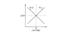
次に、制御部41によるトルクセンサ94における異常の判定について説明する。制御部41は、トルクセンサ94に異常が生じているか否かを判定する。トルクセンサ94は、2つの検出素子を備え、その2つの検出素子が、それぞれステアリングシャフト92の回転に伴うトルクを電圧に変換し、制御部41に対して出力する。本実施形態では、2つの検出素子は逆方向のトルクを検出するように設けられており、それぞれ図6に示す電圧Vt1,Vt2を出力する。なお、2つの検出素子は、同一方向のトルクを検出するものであってもよい。トルクセンサ94を構成する検出素子は、正常時においては、同一の大きさとなる。そこで、制御部41は、トルクセンサ94を構成する2つの検出素子による出力電圧Vt1,Vt2を比較して、所定値以上のずれが生じていた場合にトルクセンサ94に異常が生じていると判定する。
Next, determination of abnormality in the
ここで、「正常判定部」としての制御部41は、上述した異常判定に加え、電動パワーステアリング装置5が正常に動作するか否かの判定を行う。そして、制御部41は、外部装置としての制御装置60及び表示装置61に対して、電動パワーステアリング装置5が正常である旨を通知する。本実施形態の制御装置60は、電動パワーステアリング装置5が正常である旨が制御部41から通知されたことを条件として、手動制御から自律制御への切り替えを許可する。なお、手動制御から自律制御への切り替えを許可する主体は制御部41であってもよい。「正常判定部」としての制御部41は、所定の正常判定期間にわたって、モータ10の動作時に成立する所定の正常判定条件が成立し、且つ、異常判定条件が成立していない場合に、電動パワーステアリング装置5が正常であると判定する。
Here, the
なお、「正常判定部」としての制御部41は、第2巻線群12及び第2電源システムにおけるショート異常、オープン異常、第2電流検出部27の異常、及び、第2角度センサ29の異常に係る正常判定を実施するが、第1巻線群11及び第1電源システムにおけるショート異常、オープン異常、第1電流検出部26の異常、及び、第1角度センサ28の異常に係る正常判定と同等であるため、説明を省略する。
Note that the
「正常判定部」としての制御部41は、ショート異常に係る正常判定時において、第1電流検出部26による相電流Iu1,Iv1,Iv2の検出値が所定値を超えることを異常判定条件とするともに、正常判定条件とする。
The
「正常判定部」としての制御部41は、オープン異常に係る正常判定時において、第1インバータ部21が所定電圧を出力している状況下で第1電流検出部26による相電流Iu1,Iv1,Iw2の検出値のいずれかが所定の閾値を下回ることを異常判定条件とする。また、制御部41は、第1電流検出部26による相電流Iu1,Iv1,Iv2の検出値それぞれが所定の閾値を超えることを正常判定条件とする。
The
また、「正常判定部」としての制御部41は、第1電流検出部26の正常判定時において、第1電流検出部26による相電流Iu1,Iv1,Iw1の検出値の合計値の大きさが所定の閾値を超えることを異常判定条件とする。また、制御部41は、第1電流検出部26による相電流Iu1,Iv1,Iw1の検出値の大きさがそれぞれ所定の閾値を超えることを正常判定条件とする。
In addition, the
また、「正常判定部」としての制御部41は、第1角度センサ28の正常判定時において、第1角度センサ28を構成する2つの検出素子の出力値を比較して、所定の閾値を超えるずれが生じていることを異常判定条件とする。また、制御部41は、第1角度センサ28の検出値が所定の範囲で変化したことを正常判定条件とする。具体的には、第1角度センサ28の検出値θ1の変化量を積算した値が所定の閾値(例えば、360度)を超えていることを正常判定条件とする。また、モータ10が第1角度センサ28の検出範囲の半分以上、即ち、180度以上回転したことを判定できるように所定の範囲を設定してもよい。
The
また、第1角度センサ28による電気角θの検出範囲を所定数の区画に分割し、第1角度センサ28の検出値θ1が所定数の区画を通過したことを正常判定条件としてもよい。例えば、第1角度センサ28による電気角θの検出範囲を6つの区画、即ち、第1区画:0度〜60度、第2区画:60度〜120度、第3区画:120度〜180度、第4区画:180度〜240度、第5区画:240度〜300度、第6区画:300度〜360度に分割する。そして、第1角度センサ28の検出値θ1が、第1〜第6区画の全てを通過したこと(第1角度センサ28の検出値θ1が、各区画に属する値のいずれかと等しくなったこと)を正常判定条件としてもよい。なお、第1角度センサ28の検出値θ1が、第1〜第6区画のうち所定数(例えば、3つの区画)を通過したことを正常判定条件としてもよい。
Further, the detection range of the electrical angle θ by the
また、「正常判定部」としての制御部41は、トルクセンサ94を構成する第1検出素子の出力値Vt1の大きさと第2検出素子の出力値Vt2の大きさとを比較して、所定の閾値を超えるずれが生じていることを異常判定条件とする。また、制御部41は、トルクセンサ94によるトルクの検出値の大きさが所定値を超えることを正常判定条件とする。
Further, the
図7にショート異常に係る異常判定及び正常判定処理を表すフローチャートを示す。当該処理は制御部41によって実施される。ステップS01〜S05の処理が「異常判定部」としての制御部41による処理に相当し、ステップS01〜S09が「正常判定部」としての制御部41による処理に相当する。
FIG. 7 is a flowchart showing the abnormality determination and normality determination processing related to the short abnormality. The process is performed by the
ステップS01において、第1電流検出部26からU1相、V1相、W1相に流れる電流Iu1,Iv1,Iw1の検出値を取得し、相電流Iu1,Iv1,Iw1の検出値の大きさのいずれかが所定の閾値(例えば、100A)を超えているか否かを判定する。ここで、ステップS01の判定に用いる閾値は、第1インバータ部21から第1巻線群11に電流が流れる経路において、ショート異常が生じていることが判定可能な値に設定されている。つまり、ステップS01の判定に用いる閾値は、モータ10の正常動作時における相電流Iu1,Iv1,Iw1の検出値の大きさより大きく、ショート異常の発生時の相電流Iu1,Iv1,Iw1の検出値の大きさより小さい値に設定されている。
In step S01, the detection values of the currents Iu1, Iv1, and Iw1 flowing in the U1, V1, and W1 phases are acquired from the first
ステップS01において肯定的な判断がなされた場合(S01:YES)、即ち、ショート異常に係る異常判定条件が成立している場合、ステップS02において、異常カウンタを1増加させる。なお、異常カウンタの初期値は0に設定されている。また、ステップS01において否定的な判断がなされた場合(S01:NO)、即ち、ショート異常に係る異常判定条件が成立していない場合、ステップS03において、異常カウンタを0に初期化する。ステップS02,S03の後、ステップS04において、異常カウンタの値が所定値(例えば、50)以下か否かを判定する。異常カウンタの値が所定値より大きい場合(S04:NO)、ステップS05においてショート異常が発生していると判定を行い、当該異常判定の結果を制御装置80に通知し、処理を終了する。 If an affirmative determination is made in step S01 (S01: YES), that is, if the abnormality determination condition relating to the short circuit abnormality is satisfied, the abnormality counter is incremented by 1 in step S02. Note that the initial value of the abnormality counter is set to zero. If a negative determination is made in step S01 (S01: NO), that is, if the abnormality determination condition relating to the short abnormality is not satisfied, the abnormality counter is initialized to 0 in step S03. After steps S02 and S03, in step S04, it is determined whether or not the value of the abnormality counter is a predetermined value (for example, 50) or less. If the value of the abnormality counter is larger than the predetermined value (S04: NO), it is determined that a short abnormality has occurred in step S05, the result of the abnormality determination is notified to the control device 80, and the process is terminated.
ステップS04において異常カウンタの値が所定値以下であると判定された場合(S04:YES)の後、ステップS06において、異常カウンタが0であるか否かを判定する。異常カウンタが0より大きい場合(S06:NO)、ステップS01以降の処理を繰り替えし実施する。異常カウンタが0の場合(S06:YES)、ステップS07において、正常カウンタを1増加させる。なお、正常カウンタの初期値は0に設定されている。ステップS08において、正常カウンタが50より大きいか否かを判定する。正常カウンタが50以下の場合(S08:NO)、ステップS09において、ショート異常が生じていないとする正常判定を行い、当該正常判定の結果を制御装置80に通知し、ステップS01以降の処理を繰り返し実施する。 If it is determined in step S04 that the value of the abnormality counter is equal to or smaller than the predetermined value (S04: YES), it is determined in step S06 whether the abnormality counter is 0 or not. When the abnormality counter is larger than 0 (S06: NO), the processes after step S01 are repeated and executed. If the abnormality counter is 0 (S06: YES), the normal counter is incremented by 1 in step S07. The initial value of the normal counter is set to 0. In step S08, it is determined whether or not the normal counter is greater than 50. If the normal counter is 50 or less (S08: NO), it is determined in step S09 that no short circuit abnormality has occurred, the result of the normal determination is notified to the control device 80, and the processing from step S01 is repeated. carry out.
図8にオープン異常に係る異常判定及び正常判定処理を表すフローチャートを示す。当該処理は制御部41によって実施される。図7と同等の処理については同一の符号を付し、適宜説明を省略する。また、図7に示す異常カウンタ及び正常カウンタと、図8に示す異常カウンタ及び正常カウンタとは、説明の便宜上同一の名前を付しているが異なる変数である。
FIG. 8 is a flowchart showing the abnormality determination and normality determination processing related to the open abnormality. The process is performed by the
図8に示すフローチャートでは、図7のステップS01に代えて、ステップS11の処理を実行し、ステップS04の肯定的な判断とステップS06の処理との間でステップS12の処理を実行する。ステップS11,S02〜S05の処理が「異常判定部」としての制御部41による処理に相当し、ステップS11,S02〜S05,S12,S06〜S09の処理が「正常判定部」としての制御部41による処理に相当する。
In the flowchart shown in FIG. 8, the process of step S11 is executed instead of step S01 of FIG. 7, and the process of step S12 is executed between the positive determination of step S04 and the process of step S06. The processing of steps S11, S02 to S05 corresponds to the processing by the
ステップS11では、オープン異常時の異常判定条件が成立しているか否かを判定する。具体的には、相電流Iu1,Iv1,Iw1の検出値、バッテリ30の出力電圧(電源電圧)の検出値、第1インバータ部21の出力電圧の指令値Vu1*,Vv1*,Vw1*、及び、モータ10の回転速度を取得する。そして、電源電圧の検出値が所定値(例えば、9V)より大きく、且つ、出力電圧の指令値Vu1*,Vv1*,Vw1*のそれぞれが所定値(例えば、5V)より大きく、且つ、モータ10の回転速度が所定値(例えば500rpm)より小さく、且つ、相電流Iu1,Iv1,Iw1の検出値の少なくとも一つが所定の閾値(30A)より小さい場合に、オープン異常が生じていると判定する。ステップS11において肯定的な判断がなされた場合、ステップS02の処理に進み、ステップS11において否定的な判断がなされた場合、ステップS03の処理に進む。
In step S11, it is determined whether an abnormality determination condition at the time of an open abnormality is satisfied. Specifically, the detected values of the phase currents Iu1, Iv1, Iw1, the detected value of the output voltage (power supply voltage) of the
ステップS12では、相電流Iu1,Iv1,Iw1の検出値の大きさのうち少なくとも一が、所定の閾値(5A)より大きいか否かを判定する。相電流Iu1,Iv1,Iw1の検出値の大きさのうち少なくとも一つが、所定の閾値(5A)より大きい場合(S12:YES)、ステップS06以降の処理を実施する。また、相電流Iu1,Iv1,Iw1の検出値の大きさのいずれもが、所定の閾値(5A)以下の場合(S12:NO)、再度ステップS11以降の処理を実施する。 In step S12, it is determined whether at least one of the magnitudes of the detected values of the phase currents Iu1, Iv1, Iw1 is greater than a predetermined threshold value (5A). When at least one of the magnitudes of the detected values of the phase currents Iu1, Iv1, Iw1 is larger than the predetermined threshold (5A) (S12: YES), the processes after step S06 are performed. Further, when the magnitudes of the detected values of the phase currents Iu1, Iv1, and Iw1 are not more than the predetermined threshold value (5A) (S12: NO), the processes after step S11 are performed again.
図9に第1電流検出部26に係る異常判定及び正常判定処理を表すフローチャートを示す。当該処理は制御部41によって実施される。図6と同等の処理については同一の符号を付し、適宜説明を省略する。図9に示すフローチャートでは、図6のステップS01に代えて、ステップS21の処理を実行し、ステップS04の肯定的な判断とステップS06の処理との間にステップS22の処理を実行する。ステップS21,S02〜S05の処理が「異常判定部」としての制御部41による処理に相当し、ステップS21,S02〜S05,S22,S06〜S09の処理が「正常判定部」としての制御部41による処理に相当する。
FIG. 9 is a flowchart showing the abnormality determination and normality determination processing related to the first
ステップS21では、第1電流検出部26に係る異常判定条件が成立しているか否かを判定する。具体的には、相電流Iu1,Iv1,Iw1の検出値の合計値の大きさが所定の閾値(5A)より大きいか否かを判定する。相電流Iu1,Iv1,Iw1の検出値の合計値の大きさが所定の閾値(5A)より大きい場合、電流検出素子261,262,263の少なくとも一つおいて異常(例えば、出力値が常に0になる異常)が生じていると判定する。ステップS21において肯定的な判断がなされた場合、ステップS02の処理に進み、ステップS21において否定的な判断がなされた場合、ステップS03の処理に進む。
In step S <b> 21, it is determined whether an abnormality determination condition related to the first
ステップS22では、相電流Iu1,Iv1,Iw1の検出値の大きさのうち少なくとも一が、所定の閾値(5A)より大きいか否かを判定する。相電流Iu1,Iv1,Iw1の検出値の大きさのうち少なくとも一つが、所定の閾値(5A)より大きい場合(S22:YES)、ステップS06以降の処理を実施する。また、相電流Iu1,Iv1,Iw1の検出値の大きさのいずれもが、所定の閾値(5A)以下の場合(S22:NO)、再度ステップS21以降の処理を実施する。 In step S22, it is determined whether at least one of the detected values of the phase currents Iu1, Iv1, Iw1 is greater than a predetermined threshold (5A). When at least one of the magnitudes of the detected values of the phase currents Iu1, Iv1, and Iw1 is larger than the predetermined threshold (5A) (S22: YES), the processes after step S06 are performed. Further, when the magnitudes of the detected values of the phase currents Iu1, Iv1, and Iw1 are not more than the predetermined threshold value (5A) (S22: NO), the processes after step S21 are performed again.
図10に第1角度センサ28に係る異常判定及び正常判定処理を表すフローチャートを示す。当該処理は制御部41によって実施される。図6と同等の処理については同一の符号を付し、適宜説明を省略する。図10に示すフローチャートでは、図6のステップS01に代えて、ステップS31の処理を実行し、ステップS04の肯定的な判断とステップS06の処理との間にステップS32の処理を実行する。ステップS31,S02〜S05の処理が「異常判定部」としての制御部41による処理に相当し、ステップS31,S02〜S05,S32,S06〜S09の処理が「正常判定部」としての制御部41による処理に相当する。
FIG. 10 is a flowchart showing the abnormality determination and normality determination processing related to the
ステップS31では、第1角度センサ28に異常が生じているか否かを判定する。具体的には、余弦波電圧Vx1,Vx2の間で所定値(例えば、0.2V)以上の差異が生じている場合、又は、正弦波電圧Vy1,Vy2の間で所定値(例えば、0.2V)以上の差異が生じている場合、第1角度センサ28に異常が生じていると判定する。ステップS31において肯定的な判断がなされた場合、ステップS02の処理に進み、ステップS31において否定的な判断がなされた場合、ステップS03の処理に進む。
In step S31, it is determined whether or not an abnormality has occurred in the
ステップS32では、第1角度センサ28から入力されるモータ10の電気角θ1の変化量の積算値が所定値(例えば、360度)を超えているか否かを判定する。第1角度センサ28から入力されるモータ10の電気角θ1の変化量の積算値が所定値を超えている場合(S32:YES)、ステップS06以降の処理を実施する。また、第1角度センサ28から入力されるモータ10の電気角θ1の変化量の積算値が所定値以下の場合(S32:NO)、再度ステップS31以降の処理を実施する。
In step S32, it is determined whether or not the integrated value of the change amount of the electrical angle θ1 of the
図11にトルクセンサ94に係る異常判定及び正常判定処理を表すフローチャートを示す。当該処理は制御部41によって実施される。図6と同等の処理については同一の符号を付し、適宜説明を省略する。図11に示すフローチャートでは、図6のステップS01に代えて、ステップS41の処理を実行し、ステップS03の処理とステップS06の処理との間にステップS42の処理を実行する。ステップS41,S02〜S05の処理が「異常判定部」としての制御部41による処理に相当し、ステップS41,S02〜S05,S42,S06〜S09の処理が「正常判定部」としての制御部41による処理に相当する。
FIG. 11 is a flowchart showing abnormality determination and normality determination processing related to the
ステップS41では、トルクセンサ94に異常が生じているか否かを判定する。具体的には、トルクセンサ94の第1検出素子によるトルクの検出値と、トルクセンサ94の第2検出素子によるトルクの検出値とを比較して、所定値以上のずれが生じている場合、トルクセンサ94において異常が生じていると判定する。ステップS41において肯定的な判断がなされた場合、ステップS02の処理に進み、ステップS41において否定的な判断がなされた場合、ステップS03の処理に進む。
In step S41, it is determined whether or not an abnormality has occurred in the
ステップS42では、トルクセンサ94から入力されるハンドル91のトルクの検出値が所定値(例えば、0.5Nm)より大きいか否かを判定する。トルクセンサ94入力されるトルクの検出値が所定値より大きい場合(S42:YES)、ステップS06以降の処理を実施する。また、トルクセンサ94から入力されるトルクの検出値が所定値以下の場合(S42:NO)、再度ステップS41以降の処理を実施する。
In step S42, it is determined whether or not the detected value of the torque of the
図12に手動制御から自律制御への切り替え処理を表すフローチャートを示す。当該処理は、制御装置60によって所定周期毎に実施される。 FIG. 12 shows a flowchart showing a switching process from manual control to autonomous control. This process is performed by the control device 60 at predetermined intervals.
ステップS51において、操作部63から手動制御から自律制御への切り替え指令が入力されているか否かを判定する。切り替え指令が入力されていない場合(S51:NO)、処理を終了する。切り替え指令が入力されている場合(S51:YES)、ステップS52において、電動パワーステアリング装置5に異常が発生している旨の判定が制御部41によってなされているか否かを判定する。
In step S51, it is determined whether or not a switching command from manual control to autonomous control is input from the operation unit 63. If no switching command is input (S51: NO), the process is terminated. When the switching command is input (S51: YES), in step S52, it is determined whether or not the
電動パワーステアリング装置5に異常が発生している旨の判定が制御部41によってなされていない場合(S52:NO)、ステップS53において、電動パワーステアリング装置5が正常である旨の判定が制御部41によってなされているか否かを判定する。電動パワーステアリング装置5が正常である旨の通知が制御部41によってなされている場合(S53:YES)、ステップS54において、手動制御から自律制御への切り替えを実施する。電動パワーステアリング装置5に異常が発生している旨の判定が制御部41によってなされている場合(S52:YES)、ステップS57において、手動制御から自律制御への切り替えを禁止し処理を終了する。
If it is not determined by the
電動パワーステアリング装置5が正常である旨の判定が制御部41によってなされていない場合(S53:NO)、ステップS55において、インバータ部21,22から巻線群11,12に対して所定の電力パターンを供給するように制御部41に指令を行い、所定時間待機する.その後、ステップS56において、電動パワーステアリング装置5が正常である旨の判定が制御部41によってなされているか否かを再び判定する。電動パワーステアリング装置5が正常である旨の判定が制御部41によってなされている場合(S56:YES)、ステップS54において、手動制御から自律制御への切り替えを実施する。電動パワーステアリング装置5が正常である旨の通知が制御部41によってなされていない場合(S56:NO)、ステップS57において、手動制御から自律制御への切り替えを禁止し処理を終了する。
If the determination that the electric power steering device 5 is normal is not made by the control unit 41 (S53: NO), a predetermined power pattern is applied from the
ステップS53〜57の処理により、制御装置60は、手動制御から自律制御への切り替えの際、電動パワーステアリング装置5が正常である旨の通知が制御部41から行われていないことを条件として、インバータ部21,22からモータ10に対して所定パターンの電力を供給することで正常判定条件を成立させる。そして、インバータ部21,22からモータ10に対して所定パターンの電力を供給した後に、制御部41から、電動パワーステアリング装置5が正常である旨の通知がなされたことを条件として、手動制御から自律制御への切り替えを実施する。
By the processing of Steps S53 to 57, the control device 60, on the condition that notification that the electric power steering device 5 is normal is not performed from the
ここで、ステップS55における指令に伴って、インバータ部21,22から巻線群11,12に対して供給される所定の電力パターンとは、特に、ショート異常、オープン異常、第1電流検出部26の異常、又は、第1角度センサ28の異常を検出可能な電力パターンである。
Here, the predetermined power patterns supplied from the
例えば、制御部41は、所定の電力パターンとして、モータ10に流れるd軸電流Id1,Id2が0以外の所定電流となり、かつ、モータ10に流れるq軸電流Iq1,Iq2が略0となる電力を供給する。当該電力を供給することで、モータ10の出力トルクを変動させることなく、オープン異常、及び、ショート異常に関する正常判定を実施することが可能になる。
For example, the
また、例えば、制御部41は、所定パターンの電力として、モータ10に対し、モータ10からトルクが出力されてから車両のヨーレイトが変化するまでの応答時間であるヨーレイト時定数より短い周期で変化する電力を供給する。当該電力を通電することで、車両のヨーレイトを変動させることなく、オープン異常、ショート異常、及び、第1電流検出部26に関する正常判定を実施することが可能になる。ヨーレイト時定数より短い周期で変化し、かつ、インバータ部21,22から見た巻線群11,12側の回路の時定数より長い周期で変化する電力パターンとすることで、インバータ部21,22から巻線群11,12側に電流を流すことができる。また、ヨーレイト時定数より短い周期で変化し、かつ、実効値が0となるようにd軸電流の指令値Id1*,Id2*が変化する電力パターンを供給することで、モータ10におけるヨーレイトの変動を抑えることができる。
Further, for example, the
また、例えば、制御部41は、所定パターンの電力として、巻線群11,12において、出力トルクが打ち消しあう電力パターンをインバータ部21,22から供給する。当該電力パターンを供給することで、モータ10の出力トルクを変動させることなく、オープン異常、ショート異常、及び、第1電流検出部26に関する正常判定を実施することが可能になる。
In addition, for example, the
また、制御部41は、所定の電力パターンとして、モータ10が実際に回転するような電力パターンを供給することで、第1角度センサ28に関する正常判定を行うことが可能になる。
In addition, the
(他の実施形態)
・上記実施形態の制御部41は、ショート異常、オープン異常、第1電流検出部26の異常、第1角度センサ28の異常、及び、トルクセンサ94の異常を判定する。これを変更し、制御部41が、ショート異常、オープン異常、第1電流検出部26の異常、第1角度センサ28の異常、及び、トルクセンサ94の異常のうち少なくともいずれか一つを判定する構成としてもよい。
(Other embodiments)
-The
・上記実施形態のモータ10は、2つの巻線群11,12を備える構成としたが、これを変更し、1つ、又は3つ以上の巻線群を備える構成としてもよい。
-Although the
・上記実施形態のモータ10として、永久磁石型ブラシレスモータを用いたがこれを変更してもよい。例えば、界磁巻線型ブラシレスモータを用いてもよい。
-Although the permanent magnet type brushless motor was used as the
・自律運転制御装置60による自律運転制御は省略してもよい。 -The autonomous driving control by the autonomous driving control device 60 may be omitted.
・回転電機システムは、ステアリングシステム以外に適用されるものであってもよい。即ち、車両の動力源として動作する回転電機を含む回転電機システムに本実施形態の構成を適用してもよい。 -A rotary electric machine system may be applied in addition to a steering system. That is, the configuration of the present embodiment may be applied to a rotating electrical machine system including a rotating electrical machine that operates as a power source for a vehicle.
5…電動パワーステアリング装置、10…モータ、21…第1インバータ部(電源システム)、22…第2インバータ部(電源システム)、26…第1電流検出部、28…第1角度センサ、41…制御部、94…トルクセンサ。 DESCRIPTION OF SYMBOLS 5 ... Electric power steering apparatus, 10 ... Motor, 21 ... 1st inverter part (power supply system), 22 ... 2nd inverter part (power supply system), 26 ... 1st electric current detection part, 28 ... 1st angle sensor, 41 ... Control unit, 94 ... torque sensor.
Claims (9)
所定の異常判定期間にわたって所定の異常判定条件が継続して成立している場合に、前記回転電機システムに異常が生じていると判定する異常判定を実施する異常判定部(41)と、
所定の正常判定期間にわたって、前記回転電機の動作時に成立する所定の正常判定条件が成立し、かつ、前記異常判定条件が成立していない場合に、前記回転電機システムが正常であると判定する正常判定を実施するとともに、前記回転電機システムが正常であると判定した場合に、外部装置に対して、前記回転電機システムが正常である旨を通知する正常判定部(41)と、を備える回転電機システム。 Rotating electrical machine system including a rotating electrical machine (10), power supply systems (21, 22) for supplying electric power to the rotating electrical machine, and sensors (26, 28, 94) for detecting predetermined state quantities used for controlling the rotating electrical machine (5)
An abnormality determination unit (41) that performs abnormality determination to determine that an abnormality has occurred in the rotating electrical machine system when a predetermined abnormality determination condition is continuously established over a predetermined abnormality determination period;
Normality that determines that the rotating electrical machine system is normal when a predetermined normality determination condition that is satisfied during operation of the rotating electrical machine is satisfied and the abnormality determination condition is not satisfied over a predetermined normality determination period A rotating electrical machine comprising: a normality determining unit (41) that performs determination and notifies an external device that the rotating electrical machine system is normal when it is determined that the rotating electrical machine system is normal system.
前記正常判定部は、前記電源システムから前記回転電機へ電流が出力されていることを前記正常判定条件として、前記ショート異常が生じていないか否かの前記正常判定を実施する請求項1に記載の回転電機システム。 The abnormality determination unit and the normality determination unit, as the abnormality determination condition, that a short abnormality has occurred in the rotating electrical machine or the power supply system,
2. The normality determination unit according to claim 1, wherein the normality determination unit performs the normality determination as to whether or not the short circuit abnormality has occurred, with the normality determination condition that current is output from the power supply system to the rotating electrical machine. Rotating electrical machine system.
前記正常判定部は、前記回転電機又は前記電源システムに所定の閾値より大きい電流が流れていることを前記正常判定条件として、前記オープン異常が生じていないか否かの前記正常判定を実施する請求項1又は2に記載の回転電機システム。 The abnormality determination unit and the normality determination unit are used as the abnormality determination condition that an open abnormality has occurred in the rotating electrical machine or the power supply system,
The normality determination unit performs the normality determination as to whether or not the open abnormality has occurred under the normality determination condition that a current larger than a predetermined threshold value is flowing in the rotating electrical machine or the power supply system. Item 3. The rotating electrical machine system according to Item 1 or 2.
前記センサは、前記回転電機の回転角度を検出する角度センサ(28,29)を含み、
前記異常判定部及び前記正常判定部は、前記角度センサの検出値に異常が生じていることを前記異常判定条件とするものであり、
前記正常判定部は、前記角度センサの検出値が所定の範囲で変化したことを前記正常判定条件として、前記角度センサの検出値が正常であるか否かの前記正常判定を実施する請求項1乃至3のいずれか1項に記載の回転電機システム。 It is applied to an electric power steering device (5) that outputs torque according to steering torque by a driver,
The sensor includes angle sensors (28, 29) for detecting a rotation angle of the rotating electrical machine,
The abnormality determination unit and the normality determination unit use the abnormality determination condition that an abnormality has occurred in the detection value of the angle sensor,
The normality determination unit performs the normality determination as to whether or not the detection value of the angle sensor is normal, with the detection value of the angle sensor changing within a predetermined range as the normality determination condition. The rotating electrical machine system according to any one of items 1 to 3.
前記センサ、前記操舵トルクを検出するトルクセンサ(94)を含み、
前記異常判定部及び前記正常判定部は、前記トルクセンサの検出値に異常が生じていることを前記異常判定条件とするものであり、
前記正常判定部は、前記トルクセンサの検出値が所定値より大きいことを条件として、前記トルクセンサの検出値が正常であるか否かの前記正常判定を実施する請求項1乃至4のいずれか1項に記載の回転電機システム。 It is applied to an electric power steering device that outputs torque according to steering torque by a driver,
Including the sensor, a torque sensor (94) for detecting the steering torque;
The abnormality determination unit and the normality determination unit use the abnormality determination condition that an abnormality has occurred in the detection value of the torque sensor,
The normality determination unit performs the normality determination as to whether or not the detected value of the torque sensor is normal on the condition that the detected value of the torque sensor is greater than a predetermined value. The rotating electrical machine system according to item 1.
前記電動パワーステアリング装置は、前記外部装置として、前記自律制御を実施する自律運転制御装置を含み、
前記自律運転制御装置は、
前記手動制御から前記自律制御への切り替えの際、前記回転電機システムが正常である旨の通知が前記正常判定部から行われていないことを条件として、前記電源システムから前記回転電機に対して所定パターンの電力を供給することで前記正常判定条件を成立させ、
前記電源システムから前記回転電機に対して前記所定パターンの電力を供給した後に、前記正常判定部から、前記回転電機システムが正常である旨の通知がなされたことを条件として、前記手動制御から前記自律制御への切り替えを実施する請求項1乃至5のいずれか1項に記載の回転電機システム。 It is applied to an electric power steering device that switches between manual control that outputs torque according to steering torque by a driver and autonomous control that outputs torque autonomously regardless of the steering torque by the driver,
The electric power steering device includes an autonomous driving control device that performs the autonomous control as the external device,
The autonomous driving control device is
When switching from the manual control to the autonomous control, a notification that the rotating electrical machine system is normal is not sent from the normality determination unit to the rotating electrical machine from the power supply system. The normal judgment condition is established by supplying pattern power,
After supplying the power of the predetermined pattern from the power supply system to the rotating electrical machine, the normality determination unit notifies that the rotating electrical machine system is normal from the manual control. The rotating electrical machine system according to any one of claims 1 to 5, wherein switching to autonomous control is performed.
前記自律運転制御装置は、前記所定パターンの電力として、前記回転電機に対し、前記回転電機からトルクが出力されてから車両のヨーレイトが変化するまでの応答時間であるヨーレイト時定数より短い周期で変化する電力パターンを供給する請求項6又は7に記載の回転電機システム。 It is applied to an electric power steering device that outputs torque according to steering torque by a driver,
The autonomous driving control device changes the electric power of the predetermined pattern at a cycle shorter than a yaw rate time constant that is a response time from when torque is output from the rotating electric machine to when the yaw rate of the vehicle changes with respect to the rotating electric machine. The rotating electrical machine system according to claim 6 or 7, wherein an electric power pattern is supplied.
前記自律運転制御装置は、前記所定パターンの電力として、前記2組の電機子巻線において、出力トルクが打ち消しあう電力を供給する請求項6乃至8のいずれか1項に記載の回転電機システム。 The rotating electrical machine includes two independent armature windings,
The rotating electrical machine system according to any one of claims 6 to 8, wherein the autonomous operation control device supplies, as the electric power of the predetermined pattern, power that cancels output torque in the two sets of armature windings.
Priority Applications (1)
| Application Number | Priority Date | Filing Date | Title |
|---|---|---|---|
| JP2016216417A JP6822074B2 (en) | 2016-11-04 | 2016-11-04 | Rotating electrical system |
Applications Claiming Priority (1)
| Application Number | Priority Date | Filing Date | Title |
|---|---|---|---|
| JP2016216417A JP6822074B2 (en) | 2016-11-04 | 2016-11-04 | Rotating electrical system |
Publications (2)
| Publication Number | Publication Date |
|---|---|
| JP2018074879A true JP2018074879A (en) | 2018-05-10 |
| JP6822074B2 JP6822074B2 (en) | 2021-01-27 |
Family
ID=62116031
Family Applications (1)
| Application Number | Title | Priority Date | Filing Date |
|---|---|---|---|
| JP2016216417A Active JP6822074B2 (en) | 2016-11-04 | 2016-11-04 | Rotating electrical system |
Country Status (1)
| Country | Link |
|---|---|
| JP (1) | JP6822074B2 (en) |
Cited By (1)
| Publication number | Priority date | Publication date | Assignee | Title |
|---|---|---|---|---|
| US11251740B2 (en) | 2017-06-30 | 2022-02-15 | Denso Corporation | Current sensor state determination device and in-vehicle rotating electric machine system having same |
Citations (5)
| Publication number | Priority date | Publication date | Assignee | Title |
|---|---|---|---|---|
| JP2008304367A (en) * | 2007-06-08 | 2008-12-18 | Denso Corp | Failure-diagnosis information collection apparatus |
| JP2013107450A (en) * | 2011-11-18 | 2013-06-06 | Jtekt Corp | Four-wheel steering control system |
| JP2013172543A (en) * | 2012-02-21 | 2013-09-02 | Omron Automotive Electronics Co Ltd | Motor control device |
| JP2014011908A (en) * | 2012-07-02 | 2014-01-20 | Toyo Electric Mfg Co Ltd | Power converter and detection method for open-circuit failure thereof |
| JP2015202019A (en) * | 2014-04-10 | 2015-11-12 | 日立オートモティブシステムズ株式会社 | Controller of electric motor |
-
2016
- 2016-11-04 JP JP2016216417A patent/JP6822074B2/en active Active
Patent Citations (5)
| Publication number | Priority date | Publication date | Assignee | Title |
|---|---|---|---|---|
| JP2008304367A (en) * | 2007-06-08 | 2008-12-18 | Denso Corp | Failure-diagnosis information collection apparatus |
| JP2013107450A (en) * | 2011-11-18 | 2013-06-06 | Jtekt Corp | Four-wheel steering control system |
| JP2013172543A (en) * | 2012-02-21 | 2013-09-02 | Omron Automotive Electronics Co Ltd | Motor control device |
| JP2014011908A (en) * | 2012-07-02 | 2014-01-20 | Toyo Electric Mfg Co Ltd | Power converter and detection method for open-circuit failure thereof |
| JP2015202019A (en) * | 2014-04-10 | 2015-11-12 | 日立オートモティブシステムズ株式会社 | Controller of electric motor |
Cited By (2)
| Publication number | Priority date | Publication date | Assignee | Title |
|---|---|---|---|---|
| US11251740B2 (en) | 2017-06-30 | 2022-02-15 | Denso Corporation | Current sensor state determination device and in-vehicle rotating electric machine system having same |
| US11616466B2 (en) | 2017-06-30 | 2023-03-28 | Denso Corporation | Current sensor state determination device and in vehicle rotating electric machine system having same |
Also Published As
| Publication number | Publication date |
|---|---|
| JP6822074B2 (en) | 2021-01-27 |
Similar Documents
| Publication | Publication Date | Title |
|---|---|---|
| JP5760830B2 (en) | Control device for three-phase rotating machine | |
| JP5622053B2 (en) | Control device for multi-phase rotating machine and electric power steering device using the same | |
| JP6769247B2 (en) | Rotating electrical system | |
| JP6287756B2 (en) | Motor control device | |
| JP5614661B2 (en) | Rotating electrical machine control device and electric power steering device using the same | |
| JP5590076B2 (en) | Control device for multi-phase rotating machine | |
| JP6358104B2 (en) | Rotating electrical machine control device | |
| JP5826292B2 (en) | Motor control device and electric power steering device | |
| JP4998836B2 (en) | Control device for multi-phase rotating machine and electric power steering device using the same | |
| JP6040963B2 (en) | Rotating machine control device | |
| CN106877755B (en) | Rotating electric machine control device and electric power steering device including the same | |
| JP6494860B2 (en) | Three-phase duplex motor device for electric power steering device | |
| JPWO2017158681A1 (en) | Electric motor control system and electric power steering apparatus provided with the same | |
| CN102916641A (en) | Multi-phase rotary machine control apparatus and electric power steering system using the same | |
| JP2019013098A (en) | State determination device current sensor, and on-vehicle rotary electric machine system | |
| JP6685427B2 (en) | Rotating electric machine control device, and electric power steering apparatus including the rotating electric machine control device | |
| JP2013048524A (en) | Control device of multi-phase rotary machine | |
| JP6488923B2 (en) | Motor control device | |
| US20190363658A1 (en) | Motor controlling method, motor controlling system, and electronic power steering system | |
| JP5625947B2 (en) | Motor control device and electric power steering device using the same | |
| JP6822074B2 (en) | Rotating electrical system | |
| US20200001915A1 (en) | Motor controlling method, motor controlling system, and electronic power steering system | |
| US20200007062A1 (en) | Motor controlling method, motor controlling system, and electronic power steering system | |
| JP5880492B2 (en) | Rotating electrical machine control device | |
| JP2019068642A (en) | Control device for multi-phase rotary machine |
Legal Events
| Date | Code | Title | Description |
|---|---|---|---|
| A621 | Written request for application examination |
Free format text: JAPANESE INTERMEDIATE CODE: A621 Effective date: 20190618 |
|
| A977 | Report on retrieval |
Free format text: JAPANESE INTERMEDIATE CODE: A971007 Effective date: 20200526 |
|
| A131 | Notification of reasons for refusal |
Free format text: JAPANESE INTERMEDIATE CODE: A131 Effective date: 20200630 |
|
| A521 | Request for written amendment filed |
Free format text: JAPANESE INTERMEDIATE CODE: A523 Effective date: 20200826 |
|
| TRDD | Decision of grant or rejection written | ||
| A01 | Written decision to grant a patent or to grant a registration (utility model) |
Free format text: JAPANESE INTERMEDIATE CODE: A01 Effective date: 20201208 |
|
| A61 | First payment of annual fees (during grant procedure) |
Free format text: JAPANESE INTERMEDIATE CODE: A61 Effective date: 20201221 |
|
| R151 | Written notification of patent or utility model registration |
Ref document number: 6822074 Country of ref document: JP Free format text: JAPANESE INTERMEDIATE CODE: R151 |