JP2018049764A - Switch unit and railway vehicle - Google Patents
Switch unit and railway vehicle Download PDFInfo
- Publication number
- JP2018049764A JP2018049764A JP2016184980A JP2016184980A JP2018049764A JP 2018049764 A JP2018049764 A JP 2018049764A JP 2016184980 A JP2016184980 A JP 2016184980A JP 2016184980 A JP2016184980 A JP 2016184980A JP 2018049764 A JP2018049764 A JP 2018049764A
- Authority
- JP
- Japan
- Prior art keywords
- switch unit
- bushing
- switch
- movable electrode
- cable
- Prior art date
- Legal status (The legal status is an assumption and is not a legal conclusion. Google has not performed a legal analysis and makes no representation as to the accuracy of the status listed.)
- Pending
Links
Images


Classifications
-
- H—ELECTRICITY
- H01—ELECTRIC ELEMENTS
- H01H—ELECTRIC SWITCHES; RELAYS; SELECTORS; EMERGENCY PROTECTIVE DEVICES
- H01H33/00—High-tension or heavy-current switches with arc-extinguishing or arc-preventing means
- H01H33/60—Switches wherein the means for extinguishing or preventing the arc do not include separate means for obtaining or increasing flow of arc-extinguishing fluid
- H01H33/66—Vacuum switches
- H01H33/666—Operating arrangements
-
- B—PERFORMING OPERATIONS; TRANSPORTING
- B60—VEHICLES IN GENERAL
- B60L—PROPULSION OF ELECTRICALLY-PROPELLED VEHICLES; SUPPLYING ELECTRIC POWER FOR AUXILIARY EQUIPMENT OF ELECTRICALLY-PROPELLED VEHICLES; ELECTRODYNAMIC BRAKE SYSTEMS FOR VEHICLES IN GENERAL; MAGNETIC SUSPENSION OR LEVITATION FOR VEHICLES; MONITORING OPERATING VARIABLES OF ELECTRICALLY-PROPELLED VEHICLES; ELECTRIC SAFETY DEVICES FOR ELECTRICALLY-PROPELLED VEHICLES
- B60L5/00—Current collectors for power supply lines of electrically-propelled vehicles
-
- B—PERFORMING OPERATIONS; TRANSPORTING
- B61—RAILWAYS
- B61C—LOCOMOTIVES; MOTOR RAILCARS
- B61C3/00—Electric locomotives or railcars
-
- B—PERFORMING OPERATIONS; TRANSPORTING
- B61—RAILWAYS
- B61G—COUPLINGS; DRAUGHT AND BUFFING APPLIANCES
- B61G5/00—Couplings for special purposes not otherwise provided for
- B61G5/06—Couplings for special purposes not otherwise provided for for, or combined with, couplings or connectors for fluid conduits or electric cables
- B61G5/10—Couplings for special purposes not otherwise provided for for, or combined with, couplings or connectors for fluid conduits or electric cables for electric cables
Abstract
Description
本発明は、鉄道車両に搭載する開閉器ユニット、および、それを用いた鉄道車両に関するものである。 The present invention relates to a switch unit mounted on a railway vehicle and a railway vehicle using the switch unit.
従来、鉄道車両などに搭載される高圧引き通しケーブルシステムは、開閉機能を有しないものが多かった。高圧引き通しケーブルシステムが開閉機能を有しないと、地絡故障が生じた場合、乗務員が手作業で地絡箇所を切り離さなければならず、大きな手間となっていた。これを改善した高圧引き通しケーブルシステムの一例として、開閉機能を持つ回路遮断ユニットを鉄道車両の屋根上に設置した、特許文献1に記載のものがある。
Conventionally, there are many high-voltage cable systems that are installed in railway vehicles and the like that do not have an opening / closing function. If the high-voltage passing cable system does not have an opening / closing function, when a ground fault occurs, the crew member has to manually disconnect the ground fault location, which is a great effort. As an example of the high-voltage lead-through cable system that improves this, there is one described in
そのケーブルシステムは、架線からの電力を集電する集電装置と、集電装置に接続され、車両の屋根上に設置された回路遮断ユニットと、回路遮断ユニットに接続された複数の電力ケーブルと、を備え、回路遮断ユニットは、屋根の上方に配置され、複数の電力ケーブルが接続されているものであり、より具体的には、同文献の図7等に示されるように、この開閉装置の8個のブッシングのうちの4個のそれぞれに、T型ケーブルヘッドを有する高電圧ケーブルが接続されているものである。 The cable system includes a current collector that collects power from an overhead wire, a circuit breaker unit connected to the current collector and installed on the roof of the vehicle, and a plurality of power cables connected to the circuit breaker unit. The circuit breaker unit is disposed above the roof and is connected to a plurality of power cables. More specifically, as shown in FIG. A high voltage cable having a T-shaped cable head is connected to each of four of the eight bushings.
特許文献1では、高電圧の課電部である開閉装置の端子部が剥き出しで気中絶縁された状態にある。一方、車両の屋根は安全上、接地電位とされているため、開閉装置の端子部と車両の屋根との距離を離隔することが必須となる。また、特許文献1の回路遮断ユニットは、本体部と制御ボックスを縦方向に分離し両者間を支持体で連結した構造であるため、必然的に進行方向から見た時の投影面積が大きくなり、鉄道車両走行時の空気抵抗も大きくなってしまうという問題があった。
In
一方で、鉄道車両の屋根等に配置される開閉装置に対してはスペース的な制約も多く、また、鉄道車両走行時の空気抵抗を小さくする面でも、特に高さと幅を低減できることが望ましい。 On the other hand, there are many space restrictions with respect to the switchgear disposed on the roof of a railway vehicle, and it is desirable that the height and width can be reduced particularly in terms of reducing the air resistance during traveling of the railway vehicle.
そこで、本発明では高さと幅を低減できる開閉器ユニット、および、それを用いた鉄道車両を提供することを目的とする。 Therefore, an object of the present invention is to provide a switch unit that can reduce the height and width, and a railway vehicle using the switch unit.
上記の課題を解決するために、本発明に係る開閉装置は、固定電極と可動電極を接離する開閉器と、前記固定電極と電気的に接続された第一のブッシング導体と、前記可動電極と電気的に接続された第二のブッシング導体と、前記開閉器に駆動力を供給する操作機構と、前記開閉器、前記第一のブッシング導体、および、前記第二のブッシング導体を覆う絶縁ケースと、を具備する開閉器ユニットであって、前記可動電極の可動方向と前記操作機構を略直線状に配置した。 In order to solve the above-described problems, a switchgear according to the present invention includes a switch that contacts and separates a fixed electrode and a movable electrode, a first bushing conductor that is electrically connected to the fixed electrode, and the movable electrode. A second bushing conductor electrically connected to the switch, an operating mechanism for supplying a driving force to the switch, an insulating case covering the switch, the first bushing conductor, and the second bushing conductor The switch unit includes: a movable direction of the movable electrode and the operation mechanism are arranged substantially linearly.
本発明によれば、高さと幅を低減できる開閉器ユニット、および、それを用いた鉄道車両を提供することが可能になる。 ADVANTAGE OF THE INVENTION According to this invention, it becomes possible to provide the switch unit which can reduce height and width, and a rail vehicle using the same.
以下、本発明を実施する上で好適となる実施例について図面を用いて説明する。尚、下記はあくまでも実施の例に過ぎず、発明の内容が下記具体的態様に限定されるものではない。本発明は、下記態様を含めて種々の態様に変形することが無論可能である。 Hereinafter, preferred embodiments for carrying out the present invention will be described with reference to the drawings. In addition, the following is only an example of implementation, and the content of the invention is not limited to the following specific embodiment. It goes without saying that the present invention can be modified into various modes including the following modes.
実施例1について図1から図6を用いて説明する。 Example 1 will be described with reference to FIGS.
まず、図1は実施例1における車両編成を示す。この図に示す如く、本実施例の鉄道車両100は一両目100a〜八両目100hの八両で編成されている。二両目100b〜六両目100fの屋根72上には、破線で示す高圧引き通しケーブルRC1〜RC5が配置されており、四両目100dと六両目100fの高圧引き通しケーブルRC3、RC5は、図示しないき電線から、パンタグラフPG1、PG2を介して電力を受電する。各高圧引き通しケーブルは直線ジョイントSJ1〜SJ4で車両間を接続されており、また、高圧引き通しケーブルRC3、RC5は、T分岐ジョイントTJ1、TJ2で車両床下方向に分岐されている。このT分岐ジョイントTJ1と直線ジョイントSJ2、および、T分岐ジョイントTJ2と直線ジョイントSJ4はそれぞれ一体に構成され、図3で詳細説明する高圧引き通しケーブル用開閉器である開閉器ユニット70a、70bの一部を構成する。
First, FIG. 1 shows vehicle formation in the first embodiment. As shown in this figure, the
次に、図2を用いて鉄道車両100のき電回路を説明する。ここに示すように、二両目100b、四両目100d、六両目100fの床下(Bottom)には、それぞれ、受電用真空遮断器VCB1、VCB2、VCB3、および、主変圧器Tr1、Tr2、Tr3が設けられている。
Next, the feeder circuit of the
また、二両目100bの高圧引き通しケーブルRC1は、床下に設けられた受電用真空遮断器VCB1の1次側に直接接続され、受電用真空遮断器VCB1の2次側は主変圧器Tr1の1次巻線に接続され、主変圧器Tr1の2次巻線は電動機に電力を供給し、3次巻線はエアコンや照明などの補器へ電力を供給する。同じく、四両目100dと六両目100fのT分岐ユニットTJ1、TJ2で分岐された高圧引き通しケーブルはそれぞれ、床下に設けられた受電用真空遮断器VCB2、VCB3の1次側に接続され、受電用真空遮断器VCB2、VCB3の2次側は主変圧器Tr2、Tr3の1次巻線に接続され、主変圧器Tr2、Tr3の2次巻線は電動機に電力を供給し、3次巻線は補器へ電力を供給する。
Further, the high-voltage passing cable RC1 of the
上述したように、鉄道車両の屋根72上の高圧引き通しケーブルシステムに地絡故障が生じた場合、作業者が屋根72の上に登って地絡箇所を切り離すのは利便性を欠くため、極力登らずに作業出来ることが好ましい。また、屋根72上に機器を配置する場合、車両の屋根72の特に高さ方向でのスペースの制約が大きく、電気機器も高さを低減できることが望まれる。
As described above, when a ground fault occurs in the high-voltage passing cable system on the
図2の回路において、三両目100cの高圧引き通しケーブルRC2で地絡故障Faultが発生した場合には、外部からの指令により開閉器ユニット70aを動作させ、直線ジョイントSJ2を自動で開放することで、地絡故障Faultの影響を受ける主変圧器Tr1およびそれに接続された電動機を切り離す。このとき、地絡故障Faultの影響を受けない主変圧器Tr2、Tr3は接続されたままであるので、それらに接続された電動機を用いて車両100の運転を続行することができる。
In the circuit of FIG. 2, when a ground fault Fault occurs in the high-voltage passing cable RC2 of the
本実施例では、符号Faultで示した位置で地絡故障が生じた場合を例に説明しているため、故障の波及を防ぐべく、開閉器ユニット70aを動作させて直線ジョイントSJ2を開放しているが、地絡故障の場所に応じて、動作させる開閉器ユニット70、すなわち、切り離しを行う直線ジョイントSJが変わるのは言うまでも無い。本構造とすることで、車両の屋根72上に作業者が登ることなく、不具合箇所を含む高電圧ケーブルと健全な高電圧ケーブルとを自動的に分離することができる。
In this embodiment, the case where a ground fault has occurred at the position indicated by the symbol “Fault” has been described as an example. Therefore, in order to prevent the failure from spreading, the
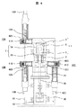
図3の上面図および図6Aの側面図を用いて、本実施例の開閉器ユニット70(高圧引き通しケーブル用開閉器)の詳細を示す。これらの図面に示すように、開閉器ユニット70は、主に、固定側に接続されたケーブルと可動側に接続されたケーブルを接離する開閉器として作用する真空インタラプタ1と、その接離に要する駆動力を発生させる操作機構として作用する電磁操作器30を直線状に並べて構成したものである。
Details of the switch unit 70 (switch for a high-voltage passing cable) according to this embodiment will be described with reference to the top view of FIG. 3 and the side view of FIG. 6A. As shown in these drawings, the
電磁操作器30の詳述は省略するが、例えば、バネに永久磁石と電磁石を組み合わせ、電磁石を構成するコイルへの通電をON/OFF切り換えることで駆動力を発生させるものであり、それらを機構ケース82で覆って構成されたものである。
Although detailed description of the
一方、真空インタラプタ1は、固定電極3と、固定電極3に対して接触または開離する可動電極5と、両電極の周囲を覆うアークシールド6と、アークシールド6を支持し真空インタラプタ1の外側容器の一部を構成する円筒形状のセラミック絶縁筒7と、ベローズ2等から構成されており、セラミック絶縁筒7の両端を端板で覆うことで、その内部を真空状態に維持している。なお、セラミック絶縁筒7は、セラミック絶縁筒7Aとセラミック絶縁筒7Bから構成されており、両者の間にアークシールド6のフランジを挟むことで、アークシールド6を固定している。
On the other hand, the
真空インタラプタ1の固定電極3は、真空インタラプタ1の外に引き出された固定導体を介してブッシング導体12Aと電気的に接続されている。また、可動電極5は、真空インタラプタ1の外に引き出された可動導体を介してブッシング導体12B、12Cと電気的に接続されるとともに、電磁操作器30が駆動する気中絶縁操作ロッド20によって固定電極3との接離が制御される。ブッシング中心導体12A、12B、12Cと絶縁ケース21を構成する絶縁物が組み合わされることで、ブッシング10A、10B、10Cが形成される。この構成により、固定側のブッシング10Aを、可動側のブッシング10B、10Cから切り離すことができる。ベローズ2は、可動導体と可動側の端版の間に配置されて、真空インタラプタ1の真空状態を維持したまま可動導体が可動出来る様にしている。
The fixed
開閉器ユニット70の外殻をなすエポキシ樹脂などで形成された絶縁ケース21は、真空インタラプタ1、固定側のブッシング導体12A、可動側のブッシング導体12B、12C等をモールドして封入するとともに、所定の周囲空間を残しながら、気中絶縁操作ロッド20の周囲を覆っている。気中絶縁操作ロッド20の周囲の空間は、絶縁ケース21と封止手段によって封止し、内部には乾燥空気やSF6ガスなどの絶縁ガスを封入している。なお、封止手段としては直線シールやベローズが適用される。気中絶縁操作ロッド20は電磁操作器30に接続されている。
An insulating
以上で説明した開閉器ユニット70は、絶縁ケース21に設けたステー83A、および、機構ケース82に設けたステー83B、83Cを介して、ベース81にボルト締結などで固定され、鉄道車両100への搭載時には、鉄道車両100の屋根72とベース81が接するように設置される。
The
図4は、図3の開閉器ユニット70を、可動電極5の可動方向と鉄道車両100の進行方向が略一致するように、かつ、鉄道車両100の屋根72上と接するように設置し、ブッシング10A、10B、10Cのそれぞれに、ケーブル42A、42B、42Cを接続した状態を示す図である。ここに示すケーブル42Aは鉄道車両の前方(図1、図2の左方向)へ引き通され、また、ケーブル42Bは鉄道車両100の後方(図1、図2の右方向)へ引き通され、ケーブル42Cは床下の受電用真空遮断器VCBを介して主変圧器Trに接続されるものである。すなわち、開閉器ユニット70は、ケーブル42Aとケーブル42Bを接続する直線ジョイントSJとしての機能と、ケーブル42Cを分岐するT型ジョイントTJとしての機能を有するものである。
FIG. 4 shows that the
図4に示す様に、各ケーブルのT型ケーブルヘッド40A、40B、40Cを接続するブッシング10A、10B、10Cを進行方向に対して側方に配置し、それらを真空インタラプタ1と略同一平面内に配置したことで、前後方向に直線状に並ぶ絶縁ケース21(真空インタラプタ1)および機構ケース82(電磁操作器30)と干渉しないように複数のケーブルを接続できるため、絶縁ケース21(真空インタラプタ1)と機構ケース82(電磁操作器30)を上下方向あるいは左右方向に並べた従来の構成に比べ、開閉器ユニット70の全高および全幅を縮小し、進行方向から見た時の投影面積を縮小することができる。これにより、鉄道車両100の屋根72上に開閉器ユニット70を設けても、それによる空気抵抗の増加を抑制することができる。なお、各T型ケーブルヘッド40A、40B、40Cは、接続端と反対側に絶縁栓41A、41B、41Cを設けており、これによりT型ケーブルヘッドの表面は接地電位に保たれている。
As shown in FIG. 4,
図5と図6Bは、図4と図6Aに示した開閉器ユニット70を、外装ケース80に収納して屋根72に設置した状態を示す図である。この外装ケース80は、前方の傾斜部と他の部分を構成する平面部によって開閉器ユニット70を覆って空気抵抗を小さくするものであるとともに、ケーブル42A〜42Cを機械的に保持することで、ブッシング10A〜10Cに偏荷重が掛からないようにしながら、鉄道車両100の屋根72に設置できるようにしたものである。図4でも説明したように、本実施例の開閉器ユニット70は、従来構造に比べ全高および全幅を縮小したものであるため、これを覆う外装ケース80も全高および全幅を小さくでき、進行方向から見た時の投影面積を小さくできる。これにより、屋根72上の開閉器ユニット70を外装ケース80で覆った場合も、それによる空気抵抗の増加を抑制することができる。
5 and 6B are views showing a state in which the
以上で説明したように、本実施例では、作業者の安全性を確保するべく、鉄道車両100の屋根72、T型ケーブルヘッド40、開閉器ユニット70の表面の何れも接地電位になっている。このため、開閉器ユニット70あるいは外装ケース80と鉄道車両100の屋根72との間で絶縁距離を確保する必要が無く、両者を近接配置しても良いため、屋根72から開閉器ユニット70あるいは外装ケース80の最高部までの高さを低減できる。より具体的には、開閉器ユニット70または外装ケース80を屋根72と接触させて配置することも可能になるため、鉄道車両の屋根72を従来より高くしたとしても、パンタグラフPGの位置を従来と同じ高さに留めることができる。
As described above, in the present embodiment, the
また、各ブッシング10A、10B、10Cは可動電極5の可動方向に対して実質的に直角な方向に配置されていることで、T型ケーブルヘッドを接続する際の作業性を向上させている。
Further, the
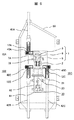
実施例2について図7を用いて説明する。なお、実施例1と共通する点は説明を省略する。 A second embodiment will be described with reference to FIG. Note that the description of the points in common with the first embodiment will be omitted.
実施例1では可動側のブッシングを二つ設けた構成を例示したが、本実施例では、可動側のブッシングを一つだけ設けている。すなわち、本実施例の開閉器ユニット70は、ケーブル42Aとケーブル42Bを接続する直線ジョイントSJとしての機能を有するが、T型ジョイントTJとしての機能を有さないものである。
In the first embodiment, the configuration in which two movable-side bushings are provided is illustrated, but in this embodiment, only one movable-side bushing is provided. That is, the
本実施例の開閉器ユニット70では、可動側ケーブルの分岐はできないが、実施例1の構成よりも横幅を小さくすることができ、鉄道車両100の屋根72上に設置したときの空気抵抗をより小さくすることができる。
In the
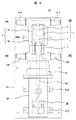
実施例3について図8を用いて説明する。なお、上述の実施例と共通する点は説明を省略する。 A third embodiment will be described with reference to FIG. Note that the description of the points in common with the above embodiment will be omitted.
実施例1では固定側のブッシングを一つだけ設けた構成を例示したが、本実施例では、固定側にもブッシングを2つ設けている。すなわち、本実施例の開閉器ユニット70は、ケーブル42Aとケーブル42Bを接続する直線ジョイントSJとしての機能と、ケーブル42Cを可動側で分岐するT型ジョイントTJとしての機能と、図示しないケーブル42Dを固定側で分岐するT型ジョイントTJとしての機能を有するものである。
In the first embodiment, a configuration in which only one fixed-side bushing is provided is illustrated, but in this embodiment, two bushings are also provided on the fixed side. That is, the
本実施例では、可動側に加え、固定側でもケーブルを分岐することが可能になるため、取り得る回路構成を拡大することができる。 In this embodiment, since the cable can be branched on the fixed side in addition to the movable side, the possible circuit configuration can be expanded.
実施例4について図9を用いて説明する。なお、上述の実施例と共通する点は説明を省略する。 Example 4 will be described with reference to FIG. Note that the description of the points in common with the above embodiment will be omitted.
実施例1では、図6の側面図等に示すように、真空インタラプタ1、気中絶縁操作ロッド20、電磁操作器30の三者を一直線に並べたが、本実施例では、図9に示すように、気中絶縁操作ロッド20と電磁操作器30の軸をずらして配置し、リンク84を介して両者を接続している。これにより、電磁操作器30と真空インタラプタ1のストロークを等しくする必要がなくなり、また、実施例1に比べて小さな出力の電磁操作器30を用いる場合であっても、梃子として作用するリンク84によって、真空インタラプタ1を適切に駆動できるため、電磁操作器30と真空インタラプタ1をぞれぞれ独立に選べるようになる。また、調整作業性が向上する。
In the first embodiment, as shown in the side view of FIG. 6 and the like, the three members of the
実施例5について図10を用いて説明する。なお、上述の実施例と共通する点は説明を省略する。 Example 5 will be described with reference to FIG. Note that the description of the points in common with the above embodiment will be omitted.
本実施例では、図3等の構成に対し、気中絶縁操作ロッド20とフランジ85の間に絶縁ガスを封止するベローズ2Aを追加している。真空インタラプタ1が閉路状態にあるときに、電磁操作器30を駆動し、固定電極3から開離するように可動電極5を移動させると、可動電極5側に設けられたベローズ2が圧縮するとともに、その反対側に設けられたベローズ2Aが伸長するため、ベローズ2の内部空間が減少すると同時に、ベローズ2Aの内部空間が増加する。本実施例では、図10に示すように、ベローズ2とベローズ2Aの直径を略等しくしており、また、同軸配置されたベローズ2の圧縮量とベローズ2Aの伸長量は等しいため、ベローズ2の圧縮による容積減少量と、ベローズ2Aの伸長による容積増加量は略等しい。すなわち、真空インタラプタ1を閉路状態から開路状態にするときに、両ベローズに挟まれた気中絶縁操作ロッド20の周囲空間は増減しない。同様の理由により、真空インタラプタ1を開路状態から閉路状態にするときにも、両ベローズに挟まれた気中絶縁操作ロッド20の周囲空間は増減しない。
In the present embodiment, a bellows 2A for sealing an insulating gas is added between the air-insulating
これにより、真空インタラプタ1が開閉動作しても、気中絶縁操作ロッド20周囲の容積変化がごく小さくなるため、真空インタラプタ1を開閉するときに要する開閉操作力を小さくできる。
Thereby, even if the
1 真空インタラプタ
2、2A ベローズ
3 固定電極
5 可動電極
6 アークシールド
7 セラミック絶縁筒
10A、10B、10C ブッシング
12A、12B、12C ブッシング導体
20 気中絶縁操作ロッド
21 絶縁ケース
30 電磁操作器
40A、40B、40C T型ケーブルヘッド
41A、41B、41C 絶縁栓
42A、42B、42C ケーブル
70、70a、70b 開閉器ユニット
72 屋根
80 外装ケース
81 ベース
82 機構ケース
83A、83B、83C ステー
84 リンク
85 フランジ
DESCRIPTION OF
Claims (9)
前記固定電極と電気的に接続された第一のブッシング導体と、
前記可動電極と電気的に接続された第二のブッシング導体と、
前記開閉器に駆動力を供給する操作機構と、
前記開閉器、前記第一のブッシング導体、および、前記第二のブッシング導体を覆う絶縁ケースと、
を具備する開閉器ユニットであって、
前記可動電極の可動方向と前記操作機構を略直線状に配置したことを特徴とする開閉器ユニット。 A switch that contacts and separates the fixed electrode and the movable electrode;
A first bushing conductor electrically connected to the fixed electrode;
A second bushing conductor electrically connected to the movable electrode;
An operating mechanism for supplying a driving force to the switch;
An insulating case covering the switch, the first bushing conductor, and the second bushing conductor;
A switch unit comprising:
A switch unit characterized in that the movable direction of the movable electrode and the operation mechanism are arranged substantially linearly.
前記第一のブッシングと前記第二のブッシングは、前記絶縁ケースの側方に設けられていることを特徴とする開閉器ユニット。 The switchgear unit according to claim 1, wherein
The switch unit, wherein the first bushing and the second bushing are provided on a side of the insulating case.
前記開閉器、前記第一のブッシング、および、前記第二のブッシングは、略同一平面内に配置されることを特徴とする高圧引き通しケーブル用開閉器。 In the switch unit according to claim 1 or 2,
The switch for a high-voltage lead-through cable, wherein the switch, the first bushing, and the second bushing are arranged in substantially the same plane.
前記絶縁ケースには、さらに、
前記第一のブッシング導体に接続された第三のブッシング、または、
前記第二のブッシング導体に接続された第四のブッシングを有することを特徴とする開閉器ユニット。 The switch unit according to any one of claims 1 to 3,
The insulating case further includes
A third bushing connected to the first bushing conductor, or
A switch unit comprising a fourth bushing connected to the second bushing conductor.
前記可動電極と前記操作機構は同軸に配置されており、それらと同軸に設けられた絶縁操作ロッドを介して駆動力が供給されることを特徴とする開閉器ユニット。 In the switch unit according to any one of claims 1 to 4,
The switch unit, wherein the movable electrode and the operation mechanism are arranged coaxially, and a driving force is supplied through an insulating operation rod provided coaxially with the movable electrode.
前記可動電極と前記操作機構は異なる高さに配置されており、前記可動電極と同軸に設けられた絶縁操作ロッド、および、該絶縁操作ロッドと前記操作機構を接続するリンクを介して駆動力が供給されることを特徴とする開閉器ユニット。 In the switch unit according to any one of claims 1 to 4,
The movable electrode and the operation mechanism are arranged at different heights, and a driving force is generated via an insulating operation rod provided coaxially with the movable electrode, and a link connecting the insulation operation rod and the operation mechanism. A switch unit that is supplied.
絶縁ガスが封入された前記絶縁操作ロッドの周囲空間は、前記開閉器側に設けた第一のベローズと、前記操作機構側に設けられた第二のベローズで挟まれており、
前記絶縁操作ロッドが移動するときの、前記第一のベローズの容積変化量と、前記第二のベローズの容積変化量が略一致することを特徴とする開閉器ユニット。 In the switch unit according to claim 5 or 6,
The space around the insulating operation rod filled with insulating gas is sandwiched between a first bellows provided on the switch side and a second bellows provided on the operation mechanism side,
The switch unit, wherein the volume change amount of the first bellows and the volume change amount of the second bellows when the insulating operation rod moves substantially coincide with each other.
請求項1ないし7の何れか一項に記載の開閉器ユニットを、前記可動電極の可動方向と前記鉄道車両の進行方向が略一致するように屋根上に設置するとともに、
前記第一のブッシングに接続した第一のケーブルヘッドと、前記第二のブッシングに接続した第二のケーブルヘッドの接続を接離できることを特徴とする鉄道車両。 A railway vehicle,
The switch unit according to any one of claims 1 to 7 is installed on the roof so that the movable direction of the movable electrode and the traveling direction of the railway vehicle substantially coincide with each other,
A railway vehicle characterized in that the connection of the first cable head connected to the first bushing and the connection of the second cable head connected to the second bushing can be separated.
さらに、前記開閉器ユニットの側方と上方を覆うとともに、前記第一のケーブルヘッドに接続された第一のケーブル、および、前記第二のケーブルヘッドに接続された第二のケーブルを機械的に保持する外装ケースを有することを特徴とする鉄道車両。 The railway vehicle according to claim 8,
Further, the first cable connected to the first cable head and the second cable connected to the second cable head are mechanically covered while covering the side and upper side of the switch unit. A railway vehicle having an exterior case for holding.
Priority Applications (3)
| Application Number | Priority Date | Filing Date | Title |
|---|---|---|---|
| JP2016184980A JP2018049764A (en) | 2016-09-23 | 2016-09-23 | Switch unit and railway vehicle |
| EP17182416.2A EP3300096A1 (en) | 2016-09-23 | 2017-07-20 | Switch unit and rail car using the same |
| CN201710766971.0A CN107867184A (en) | 2016-09-23 | 2017-08-31 | Shutter unit and use its rail truck |
Applications Claiming Priority (1)
| Application Number | Priority Date | Filing Date | Title |
|---|---|---|---|
| JP2016184980A JP2018049764A (en) | 2016-09-23 | 2016-09-23 | Switch unit and railway vehicle |
Publications (2)
| Publication Number | Publication Date |
|---|---|
| JP2018049764A true JP2018049764A (en) | 2018-03-29 |
| JP2018049764A5 JP2018049764A5 (en) | 2019-02-07 |
Family
ID=59383503
Family Applications (1)
| Application Number | Title | Priority Date | Filing Date |
|---|---|---|---|
| JP2016184980A Pending JP2018049764A (en) | 2016-09-23 | 2016-09-23 | Switch unit and railway vehicle |
Country Status (3)
| Country | Link |
|---|---|
| EP (1) | EP3300096A1 (en) |
| JP (1) | JP2018049764A (en) |
| CN (1) | CN107867184A (en) |
Cited By (1)
| Publication number | Priority date | Publication date | Assignee | Title |
|---|---|---|---|---|
| WO2021140668A1 (en) * | 2020-01-10 | 2021-07-15 | 三菱電機株式会社 | Vacuum interrupter |
Families Citing this family (1)
| Publication number | Priority date | Publication date | Assignee | Title |
|---|---|---|---|---|
| FR3111733B1 (en) * | 2020-06-17 | 2022-07-01 | Alstom Transp Tech | Switching device, associated assembly and vehicle comprising such an assembly |
Family Cites Families (8)
| Publication number | Priority date | Publication date | Assignee | Title |
|---|---|---|---|---|
| FR2753834B1 (en) * | 1996-09-23 | 1998-12-04 | HIGH VOLTAGE CIRCUIT BREAKER WITH SHOCK ABSORBER | |
| JP2002124162A (en) * | 2000-10-16 | 2002-04-26 | Mitsubishi Electric Corp | Switchgear |
| JP4906892B2 (en) * | 2009-08-12 | 2012-03-28 | 株式会社日立製作所 | Switchgear |
| EP2664481A4 (en) * | 2011-01-14 | 2016-11-30 | Kawasaki Heavy Ind Ltd | Circuit breaker unit, and rolling stock provided therewith |
| CN103050320A (en) * | 2011-05-13 | 2013-04-17 | 中煤电气有限公司 | Miniaturized large-current handcart-type vacuum circuit breaker |
| JP6216529B2 (en) * | 2013-03-28 | 2017-10-18 | 株式会社日立産機システム | Railway vehicle |
| JP2015043656A (en) * | 2013-08-26 | 2015-03-05 | 株式会社東芝 | Circuit breaker |
| JP2015056239A (en) * | 2013-09-10 | 2015-03-23 | 株式会社東芝 | Circuit breaker |
-
2016
- 2016-09-23 JP JP2016184980A patent/JP2018049764A/en active Pending
-
2017
- 2017-07-20 EP EP17182416.2A patent/EP3300096A1/en not_active Withdrawn
- 2017-08-31 CN CN201710766971.0A patent/CN107867184A/en active Pending
Cited By (1)
| Publication number | Priority date | Publication date | Assignee | Title |
|---|---|---|---|---|
| WO2021140668A1 (en) * | 2020-01-10 | 2021-07-15 | 三菱電機株式会社 | Vacuum interrupter |
Also Published As
| Publication number | Publication date |
|---|---|
| EP3300096A1 (en) | 2018-03-28 |
| CN107867184A (en) | 2018-04-03 |
Similar Documents
| Publication | Publication Date | Title |
|---|---|---|
| US8710388B2 (en) | Switchgear and method for operating switchgear | |
| JP6328998B2 (en) | Unit switch, switchgear, and railway vehicle | |
| KR101736290B1 (en) | Railroad vehicle | |
| JP2018049764A (en) | Switch unit and railway vehicle | |
| JP6778129B2 (en) | Switch unit for railroad vehicles | |
| JP6713940B2 (en) | Radiator for solid insulated switchgear unit, solid insulated switchgear unit, and railway vehicle | |
| US10589760B2 (en) | Branching unit and vehicular system | |
| JP6783720B2 (en) | Vacuum switchgear | |
| JP6933598B2 (en) | Solid insulation type vacuum switch | |
| JP2018049764A5 (en) | ||
| JP6951201B2 (en) | Switch unit and railroad vehicle using it | |
| WO2023119453A1 (en) | Switch | |
| JP2013206665A (en) | Vacuum switch | |
| JPS6389005A (en) | Portable gas insulated switchgear | |
| JPH08222094A (en) | Vacuum circuit breaker, and metal closed type switch gear |
Legal Events
| Date | Code | Title | Description |
|---|---|---|---|
| A521 | Written amendment |
Free format text: JAPANESE INTERMEDIATE CODE: A523 Effective date: 20181220 |
|
| A621 | Written request for application examination |
Free format text: JAPANESE INTERMEDIATE CODE: A621 Effective date: 20181220 |
|
| A131 | Notification of reasons for refusal |
Free format text: JAPANESE INTERMEDIATE CODE: A131 Effective date: 20191001 |
|
| A977 | Report on retrieval |
Free format text: JAPANESE INTERMEDIATE CODE: A971007 Effective date: 20190927 |
|
| A02 | Decision of refusal |
Free format text: JAPANESE INTERMEDIATE CODE: A02 Effective date: 20200324 |