JP2018043255A - Meandering prediction system and meandering prediction method - Google Patents
Meandering prediction system and meandering prediction method Download PDFInfo
- Publication number
- JP2018043255A JP2018043255A JP2016178307A JP2016178307A JP2018043255A JP 2018043255 A JP2018043255 A JP 2018043255A JP 2016178307 A JP2016178307 A JP 2016178307A JP 2016178307 A JP2016178307 A JP 2016178307A JP 2018043255 A JP2018043255 A JP 2018043255A
- Authority
- JP
- Japan
- Prior art keywords
- meandering
- rolling
- plate material
- act
- cal
- Prior art date
- Legal status (The legal status is an assumption and is not a legal conclusion. Google has not performed a legal analysis and makes no representation as to the accuracy of the status listed.)
- Granted
Links
Images


Abstract
Description
本発明は、蛇行予測システム及び蛇行予測方法に関し、特に、圧延ロールの入側における板材の蛇行を予測する蛇行予測システム及び蛇行予測方法に関する。 The present invention relates to a meandering prediction system and a meandering prediction method, and more particularly to a meandering prediction system and a meandering prediction method for predicting meandering of a plate material on the entrance side of a rolling roll.
従来、タンデム式圧延機などにおいて一対の圧延ロール間に板材を通過させることにより、板材を所望の厚さに加工する技術が知られている。このような圧延加工においては、通板時間の経過と共に板材が圧延ロールの軸方向中心に対して左右にずれるように蛇行する場合がある。これにより、板材の幅方向の端部が搬送路の両サイドに衝突するなど、圧延トラブルを招くという問題がある。 Conventionally, a technique for processing a plate material to a desired thickness by passing the plate material between a pair of rolling rolls in a tandem rolling mill or the like is known. In such a rolling process, the plate material may meander so as to be shifted to the left and right with respect to the axial center of the rolling roll as the sheet passing time elapses. Thereby, there exists a problem of causing a rolling trouble, such as the edge part of the width direction of a board | plate colliding with both sides of a conveyance path.
これに対して、下記特許文献1〜3に開示されるように、圧延時に生じ得る板材の蛇行を制御するための様々な方法が検討されている。下記特許文献1,2には、圧延ロールの入側又は出側における板材の差張力を測定し、その結果に基づいて圧延ロールのレベリング調整を行う方法が開示されている。また下記特許文献3には、圧延ロールの入側における板材の差張力及び圧延ロールが板材から受ける差荷重を用いて、ファジー推論に基づいてレベリング調整量を計算する方法が開示されている。
On the other hand, as disclosed in the following
上記特許文献1〜3に提案される方法では、圧延時に起こる板材の蛇行をある程度予測することは可能であるが、以下のように実際の蛇行挙動とのずれが大きく、予測の正確性に問題があった。
In the methods proposed in
上記特許文献1,2は、圧延ロール間のギャップが広い方のサイドへ板材が蛇行するという予測のみに基づいて、圧延ロールのレベリング量を調整するものである。しかし、実際には、圧延ロール間のギャップが狭い方のサイドへ板材が寄る場合もあり、この場合はレベリング調整を行わなくても蛇行が停留する。即ち、ミル定数差などにより圧延ロールに左右のレベル差が生じている状況でも、必ずしも蛇行が進展するとは限らず、板材が圧延ロールの軸方向中心に対して若干オフセンターした状態で安定する場合がある。このため、実際の蛇行挙動とずれた予測に基づいてレベリング調整を行うと、却って蛇行の進展を助長してしまう虞がある。
In
また上記特許文献3の蛇行予測に用いられるファジー推論は、実際の圧延時に起こる蛇行のメカニズムに立脚した力学モデルに基づくものではない。よって、上記特許文献1,2と同様に板材の蛇行を正確に予測するのは困難であり、ファジー推論に基づくレベリング操作を行うことで、蛇行の進展を助長してしまう虞がある。
Further, the fuzzy inference used for meandering prediction in Patent Document 3 is not based on a dynamic model based on the meandering mechanism that occurs during actual rolling. Therefore, it is difficult to accurately predict the meandering of the plate material as in
本発明は、上記課題に鑑みてなされたものであり、その目的は、圧延時に生じ得る板材の蛇行をより正確に予測可能な蛇行予測システム及び蛇行予測方法を提供することである。 The present invention has been made in view of the above problems, and an object thereof is to provide a meandering prediction system and a meandering prediction method that can more accurately predict meandering of a plate material that may occur during rolling.
本発明の一局面に係る蛇行予測システムは、一対の圧延ロールの入側における板材の蛇行を予測するシステムである。上記蛇行予測システムは、前記圧延ロールの差荷重の実績値ΔPactと、前記圧延ロールの出側における前記板材の差張力の実績値ΔσD actと、を受け付ける受付部と、前記差荷重の計算値ΔPcalと、前記差張力の計算値ΔσD calと、を計算するための演算部と、を備える。前記演算部は、数値モデルにより前記板材の蛇行量Ys及び前記圧延ロールのレベル差ΔSを計算するように構成されている。上記蛇行予測システムは、ΔPact=ΔPcal且つΔσD act=ΔσD calの時点における前記板材の蛇行量YS及び前記圧延ロールのレベル差ΔSの計算結果を出力する出力部をさらに備える。 The meandering prediction system according to one aspect of the present invention is a system that predicts meandering of a plate material on the entry side of a pair of rolling rolls. The meandering prediction system includes a receiving unit that receives the actual value ΔP act of the differential load of the rolling roll and the actual value Δσ D act of the differential tension of the plate material on the exit side of the rolling roll, and the calculation of the differential load An arithmetic unit for calculating a value ΔP cal and a calculated value Δσ D cal of the differential tension. The calculation unit is configured to calculate a meandering amount Ys of the plate material and a level difference ΔS of the rolling rolls by a numerical model. The meander prediction system further includes an output unit for outputting the calculation result of [Delta] P act = [Delta] P cal and Δσ D act = Δσ meandering amount of the plate at the time of D cal Y S and level difference of the rolling rolls [Delta] S.
上記蛇行予測システムでは、数値モデルにより板材の蛇行量YS及び圧延ロールのレベル差ΔSを計算すると共に、圧延ロールの差荷重及び板材の出側差張力の計算値がそれぞれ実績値と一致する(ΔPact=ΔPcal、ΔσD act=ΔσD cal)時点における計算結果を出力する。これにより、差荷重及び出側差張力の実績値ΔPact,ΔσD actに対応する蛇行量YS及びレベル差ΔSの計算値を出力することが可能になり、実際の圧延時に生じ得る板材の蛇行をより正確に予測することができる。このように、蛇行量YS及びレベル差ΔSを正確に計算し、これに基づいて適切な蛇行防止措置を講じることで、蛇行による圧延トラブルの発生を未然に防止することができる。 In the meandering prediction system, the meandering amount Y S of the plate material and the level difference ΔS of the rolling roll are calculated by a numerical model, and the calculated values of the differential load of the rolling roll and the delivery side differential tension of the rolling material are coincident with the actual values ( ΔP act = ΔP cal , Δσ D act = Δσ D cal ) is output. As a result, it becomes possible to output the calculated values of the meandering amount Y S and the level difference ΔS corresponding to the actual values ΔP act and Δσ D act of the differential load and the outgoing differential tension. Meander can be predicted more accurately. Thus, accurately calculate the amount of meandering Y S and level difference [Delta] S, by appropriate meandering preventive measures based on this, it is possible to prevent the occurrence of rolling troubles due meandering in advance.
上記蛇行予測システムにおいて、前記演算部は、下記の式(1)〜(4)のヤコビアン(ヤコビ行列)J11,J12,J21,J22を計算し、前記ヤコビアンJ11,J12,J21,J22の逆行列J11 −1,J12 −1,J21 −1,J22 −1を用いて、下記の式(5),(6)により前記板材の蛇行量YS及び前記圧延ロールのレベル差ΔSを計算するように構成されていてもよい。 In the meandering prediction system, the calculation unit calculates Jacobians (Jacobi matrices) J 11 , J 12 , J 21 , J 22 of the following formulas (1) to (4), and the Jacobian J 11 , J 12 , J 21, the inverse matrix J 11 -1 of J 22, J 12 -1, J 21 -1, with a J 22 -1, the following equation (5), meandering amount Y S and the plate (6) The level difference ΔS of the rolling rolls may be calculated.
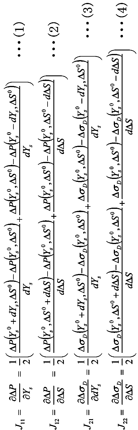
本発明者らは、実際の圧延時における蛇行挙動に即して、板材の蛇行をより正確に予測するための方策について、鋭意検討を行った。その結果、上記の式(1)〜(4)に示される蛇行モデルのヤコビアンJ(J11,J12,J21,J22)を計算し、その逆行列J−1(J11 −1,J12 −1,J21 −1,J22 −1)を用いて上記の式(5),(6)により板材の蛇行量YS及び圧延ロールのレベル差ΔSを計算するモデルに着目し、本発明に想到した。 The present inventors diligently studied a policy for more accurately predicting the meandering of the plate material in accordance with the meandering behavior during actual rolling. As a result, the meandering model Jacobian J (J 11 , J 12 , J 21 , J 22 ) represented by the above equations (1) to (4) is calculated, and its inverse matrix J −1 (J 11 −1 , J 12 −1 , J 21 −1 , J 22 −1 ) and paying attention to a model for calculating the meandering amount Y S of the plate material and the level difference ΔS of the rolling roll by the above formulas (5) and (6), The present invention has been conceived.
上記蛇行予測システムでは、ヤコビアンJの逆行列J−1を用いた上記の式(5),(6)により、板材の蛇行量YS及び圧延ロールのレベル差ΔSを計算することができる。これにより、従来のシステムとは異なり、蛇行の停留や発散を含む実際の蛇行挙動に即した正確な計算が可能になる。 In the meandering prediction system, the meandering amount Y S of the plate material and the level difference ΔS of the rolling roll can be calculated by the above equations (5) and (6) using the inverse matrix J −1 of the Jacobian J. As a result, unlike conventional systems, it is possible to calculate accurately in accordance with the actual meandering behavior including meandering stop and divergence.
上記蛇行予測システムは、前記板材の蛇行量YSの時間変化が予め定められた閾値を超えるか否かを判定するための判定部と、前記判定部において前記板材の蛇行量YSの時間変化が前記閾値を超えたと判定されたときに警報を発生する警報発生部と、をさらに備えていてもよい。 The meandering prediction system includes a determination unit for determining whether a time change of the meandering amount Y S of the plate material exceeds a predetermined threshold value, and a time change of the meandering amount Y S of the plate material in the determination unit. An alarm generation unit that generates an alarm when it is determined that the threshold value exceeds the threshold value.
この構成によれば、蛇行量YSの時間変化が閾値を超えて有害な蛇行が発生していることを、オペレータが警報によって容易に認識することができる。これにより、オペレータに対して蛇行防止措置を講じる必要があることをより確実に伝えることができる。 According to this configuration, the harmful serpentine beyond the time variation threshold in meandering amount Y S has occurred, the operator can easily recognize the warning. As a result, it is possible to more reliably notify the operator that it is necessary to take a meandering prevention measure.
上記蛇行予測システムは、タンデム式圧延機における最上流に配置された前記一対の圧延ロールと、前記タンデム式圧延機の上流側に配置された上流側ロールと、の間における前記板材の蛇行を予測するように構成されていてもよい。 The meandering prediction system predicts meandering of the plate material between the pair of rolling rolls arranged in the uppermost stream in the tandem rolling mill and the upstream roll arranged on the upstream side of the tandem rolling mill. It may be configured to.
この構成によれば、タンデム式圧延機の最上流に配置された圧延ロールの入側で生じ得る板材の蛇行を正確に予測することができる。 According to this configuration, it is possible to accurately predict the meandering of the plate material that may occur on the entry side of the rolling roll disposed in the uppermost stream of the tandem rolling mill.
本発明の他局面に係る蛇行予測方法は、一対の圧延ロールの入側における板材の蛇行を予測する方法である。上記蛇行予測方法は、前記圧延ロールの差荷重の実績値ΔPactと、前記圧延ロールの出側における前記板材の差張力の実績値ΔσD actと、を入力するステップと、前記差荷重の計算値ΔPcalと、前記差張力の計算値ΔσD calと、を計算するステップと、数値モデルにより前記板材の蛇行量YS及び前記圧延ロールのレベル差ΔSを計算するステップと、ΔPact=ΔPcal且つΔσD act=ΔσD calの時点における前記板材の蛇行量YS及び前記圧延ロールのレベル差ΔSの計算結果を出力するステップと、を備える。 The meandering prediction method according to another aspect of the present invention is a method for predicting meandering of a plate material on the entry side of a pair of rolling rolls. The meandering prediction method includes a step of inputting an actual value ΔP act of the differential load of the rolling roll and an actual value Δσ D act of the differential tension of the plate material on the exit side of the rolling roll; and calculation of the differential load A step of calculating a value ΔP cal and a calculated value Δσ D cal of the differential tension, a step of calculating a meandering amount Y S of the plate material and a level difference ΔS of the rolling roll by a numerical model, and ΔP act = ΔP cal and Δσ D act = Δσ D cal , and outputting the calculation result of the meandering amount Y S of the plate and the level difference ΔS of the rolling roll.
上記蛇行予測方法によれば、数値モデルにより板材の蛇行量YS及び圧延ロールのレベル差ΔSを計算すると共に、圧延ロールの差荷重及び板材の出側差張力の計算値がそれぞれ実績値と一致する(ΔPact=ΔPcal、ΔσD act=ΔσD cal)時点における計算結果を出力する。これにより、差荷重及び出側差張力の実績値ΔPact,ΔσD actに対応する蛇行量YS及びレベル差ΔSの計算値を得ることができ、実際の圧延時に生じ得る板材の蛇行をより正確に予測することができる。 According to the meandering prediction method, the numerical model with calculating the meandering amount Y S and level difference ΔS of the rolling rolls of sheet material, the calculated value of the outlet side differential tension differences load and plate rolling rolls coincide with each actual value (ΔP act = ΔP cal , Δσ D act = Δσ D cal ) is output. Thereby, the calculated values of the meandering amount Y S and the level difference ΔS corresponding to the actual values ΔP act and Δσ D act of the differential load and the outlet side differential tension can be obtained, and the meandering of the plate material that can occur during actual rolling can be obtained. It can be predicted accurately.
上記蛇行予測方法において、前記計算するステップは、下記の式(1)〜(4)のヤコビアンJ11,J12,J21,J22を計算するステップと、前記ヤコビアンJ11,J12,J21,J22の逆行列J11 −1,J12 −1,J21 −1,J22 −1を用いて、下記の式(5),(6)により前記板材の蛇行量YS及び前記圧延ロールのレベル差ΔSを計算するステップと、を含んでいてもよい。 In the meandering prediction method, the steps of calculating include the steps of calculating Jacobians J 11 , J 12 , J 21 , J 22 of the following formulas (1) to (4), and the Jacobians J 11 , J 12 , J 21, the inverse matrix J 11 -1 of J 22, J 12 -1, J 21 -1, with a J 22 -1, the following equation (5), meandering amount Y S and the of the plate (6) Calculating a level difference ΔS of the rolling rolls.
上記蛇行予測方法では、ヤコビアンJの逆行列J−1を用いた上記の式(5),(6)により、板材の蛇行量YS及び圧延ロールのレベル差ΔSを計算することができる。これにより、従来の計算方法とは異なり、蛇行の停留や発散を含む実際の蛇行挙動に即した正確な計算が可能になる。 In the meandering prediction method, the meandering amount Y S of the plate material and the level difference ΔS of the rolling roll can be calculated by the above formulas (5) and (6) using the inverse matrix J −1 of the Jacobian J. Thus, unlike the conventional calculation method, it is possible to perform an accurate calculation according to the actual meandering behavior including the meandering stop and divergence.
上記蛇行予測方法では、前記板材の蛇行量YSの時間変化が予め定められた閾値を超えたときに警報を発生させてもよい。 In the above-described meander prediction method may generate an alarm when the time variation in the meandering amount Y S of the plate exceeds a predetermined threshold.
この方法によれば、有害な蛇行が発生していることをオペレータが警報によって容易に認識することができる。これを受けて、オペレータが板材のセンタリングなどの適切な蛇行防止措置を講じることにより、蛇行による圧延トラブルの発生を未然に防止することができる。 According to this method, the operator can easily recognize the occurrence of harmful meandering by an alarm. In response to this, the operator can prevent the occurrence of rolling troubles due to meandering by taking appropriate meandering prevention measures such as centering of the plate material.
上記蛇行予測方法は、タンデム式圧延機における最上流に配置された前記一対の圧延ロールと、前記タンデム式圧延機の上流側に配置された上流側ロールと、の間における前記板材の蛇行を予測する方法であってもよい。 The meandering prediction method predicts meandering of the plate material between the pair of rolling rolls arranged in the uppermost stream in the tandem rolling mill and the upstream roll arranged on the upstream side of the tandem rolling mill. It may be a method to do.
この方法によれば、タンデム式圧延機の最上流に配置された圧延ロールの入側で生じ得る板材の蛇行を正確に予測することができる。 According to this method, it is possible to accurately predict the meandering of the plate material that may occur on the entry side of the rolling roll disposed in the uppermost stream of the tandem rolling mill.
以上の説明から明らかなように、本発明によれば、圧延時に生じ得る板材の蛇行をより正確に予測可能な蛇行予測システム及び蛇行予測方法を提供することができる。 As is apparent from the above description, according to the present invention, it is possible to provide a meandering prediction system and a meandering prediction method capable of more accurately predicting meandering of a plate material that may occur during rolling.
以下、図面に基づいて、本発明の実施形態につき詳細に説明する。 Hereinafter, embodiments of the present invention will be described in detail with reference to the drawings.
(実施形態1)
[タンデム式圧延機]
まず、本実施形態に係る蛇行予測システム及び蛇行予測方法が適用されるタンデム式圧延機10について、図1〜図4を参照して説明する。タンデム式圧延機10は、一対の圧延ロール11,12により鋼板などの板材2を所望の厚さに加工するためのものである。なお、タンデム式圧延機10は、一対の圧延ロール11,12を備えた複数台の圧延スタンドが上流から下流に向かって並べられたものであるが、図1は、最上流に配置された#1スタンド10Aのみを示している。
(Embodiment 1)
[Tandem type rolling mill]
First, a
#1スタンド10Aは、板材2が進入可能な隙間(ギャップ)を空けて配置された上下一対の圧延ロール11,12と、圧延ロール11,12を支持する上下一対のバックアップロール13,14と、を備える。図1に示すように、圧延ロール11,12を図略のモータにより互いに逆周りに回転させつつ板材2をロール間のギャップに進入させることにより、厚さhEの板材2を所望の厚さhD(<hE)に加工することができる。以下、hEを板材2の「入側板厚」、hDを板材2の「出側板厚」とも称する。
The # 1 stand 10A has a pair of upper and lower rolling rolls 11 and 12 arranged with a gap (gap) through which the
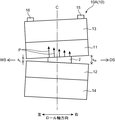
図2に示すように、#1スタンド10Aは、図中左側が作業側(Work Side;WS)となっており、図中右側が駆動側(Drive Side;DS)となっている。WS側はオペレータが作業するための領域であり、DS側は各ロール11〜14を回転させるモータなどの駆動機構が配置される領域である。
As shown in FIG. 2, the # 1 stand 10A has a working side (Work Side; WS) on the left side in the drawing, and a driving side (Drive Side; DS) on the right side in the drawing. The WS side is an area for the operator to work, and the DS side is an area where a drive mechanism such as a motor for rotating the
#1スタンド10Aは、圧延ロール11,12の左右の圧下位置(レベリング量)を調整するための手段として、図略の油圧シリンダを備える。これにより、圧延ロール11,12の左右の部分を当該シリンダのピストンによって押すことで、上下移動させることができる。よって、ミル中心C(圧延ロール11,12のロール軸方向の中心)におけるロール間の隙間を一定に維持しつつ左右の隙間を調整することで、圧延ロール11,12のレベル差ΔSを調整することができる。レベル差ΔSとは、WS側における圧延ロール11,12間の隙間SLと、DS側における圧延ロール11,12間の隙間SRとの差(SL−SR)である。よって、DS側の圧下量が大きい場合(SL>SR)にはレベル差ΔSがプラス値となり、WS側の圧下量が大きい場合(SL<SR)にはレベル差ΔSがマイナス値となる。
The # 1
図2に示すように、圧延ロール11,12は、圧延中に板材2からの反力として圧延荷重Pを受ける。#1スタンド10Aには、この圧延荷重Pを検出するための手段として、ロードセル15,16が左右に設けられている。これにより、DS側及びWS側のそれぞれにおいて、圧延ロール11,12が板材2から受ける圧延荷重Pを個別に検出することができる。そして、これらの検出値の差によって、圧延ロール11,12の差荷重の実績値ΔPactを測定することができる。つまり「圧延ロールの差荷重」とは、WS側に加わる圧延荷重PとDS側に加わる圧延荷重Pとの差であり、WS側の圧延荷重PからDS側の圧延荷重Pを引いたものである。よって、WS側の圧延荷重PがDS側の圧延荷重Pよりも大きい場合には差荷重がプラス値となり、その逆の場合には差荷重がマイナス値となる。
As shown in FIG. 2, the rolling rolls 11 and 12 receive a rolling load P as a reaction force from the
出側板厚hDは、次のように表される。即ち、圧延ロール11,12間の隙間をS、圧延荷重をP、スタンドのミル定数をMとすると、出側板厚hDは下記の式(7)により表される。ミル定数とは、スタンドの縦剛性係数であって、スタンド全体の垂直方向の変形量に対する圧延荷重の比である。なお、圧延ロール11,12の入側及び出側には、図略の板厚センサーが設けられており、これにより入側板厚hE及び出側板厚hDを各々測定することができる。 The delivery side plate thickness h D is expressed as follows. That is, assuming that the gap between the rolling rolls 11 and 12 is S, the rolling load is P, and the mill constant of the stand is M, the outlet side thickness h D is expressed by the following formula (7). The mill constant is a longitudinal rigidity coefficient of the stand, and is a ratio of the rolling load to the amount of deformation in the vertical direction of the entire stand. Note that the entry side and the delivery side of the rolling rolls 11 and 12 is provided with an unillustrated plate thickness sensor, thereby respectively measuring the thickness at entrance side h E and delivery side thickness h D.
図3に示すように、板材2は、圧延ロール11,12に対して接触弧長l(lL,lR)の長さだけ接触する。この接触弧長lは、次のように表される。即ち、圧延ロール11,12の半径をR、入側板厚をhE、出側板厚をhDとすると、接触弧長lは、下記の式(8)により表される。
As shown in FIG. 3, the
![]()
![]()
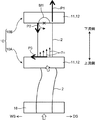
図4に示すように、圧延ロール11,12の出側には、板材2の張力を検出するための手段として、出側張力センサー17,19が設けられている。出側張力センサー17,19は、DS側及びWS側に各々設けられている。この張力センサー17,19によって、圧延ロール11,12の出側における板材2のDS側及びWS側の各張力を検出することができる。そして、これらの検出値の差から、圧延ロール11,12の出側における板材2の差張力(以下「出側差張力」とも称する)の実績値ΔσD actを測定することができる。つまり、出側差張力とは、圧延ロール11,12の出側におけるWS側の張力とDS側の張力との差であり、WS側の張力からDS側の張力を引いたものである。よって、WS側の出側張力がDS側の出側張力よりも大きい場合には出側差張力がプラス値となり、その逆の場合には出側差張力がマイナス値となる。なお、圧延ロール11,12の入側にも張力センサー(入側張力センサー)が設けられ、これによって圧延ロール11,12の入側における板材2の差張力(入側差張力)も測定可能となっていてもよい。
As shown in FIG. 4, exit
[タンデム式圧延機における板材の蛇行挙動]
次に、上記タンデム式圧延機10による圧延時において、実際に起こり得る板材2の蛇行挙動について、図5〜図8を参照して説明する。図5及び図6は、板材2の蛇行が停留する場合、即ち板材2の蛇行量が通板時間と共に増加せずに一定となる場合を示す。図7及び図8は、板材2の蛇行量が通板時間と共に増加し、蛇行が発散する場合を示す。
[Meandering behavior of plate material in tandem rolling mill]
Next, meandering behavior of the
図5に示すように、板材2は、タンデム式圧延機10の上流側に配置されたステアリングロール18(上流側ロール)に巻き付けられた状態で拘束されつつ、#1スタンド10Aの圧延ロール11,12間に進入する。そして、#1スタンド10Aを通過した板材2は、その下流に配置された#2スタンド10Bに送られる。
As shown in FIG. 5, the
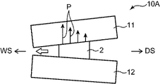
#1スタンド10Aにおいて、WS側よりもDS側のロール間ギャップが広い場合には、板材2はDS側に蛇行しようとする。より具体的には、DS側のギャップが広い状態で板材2が進入すると、図3に示すように、左右の接触弧長lL,lRに差が発生する(lL>lR)。この状態で板材2が進入すると、板材2の進行方向D1と圧延ロール11,12の回転方向D2(ロール軸方向に垂直な方向)との間に入射角θが形成される。これにより、DS側に向かう速度成分Vが発生し、当該速度成分Vにより板材2がDS側に蛇行しようとする。
In the # 1
この状態で、図5に示すように#2スタンド10Bの圧延ロール11,12間に板材2が進入すると、DS側に引張応力P1が発生すると共にWS側に圧縮応力P2が発生する。この引張応力P1及び圧縮応力P2は、板材2の長手方向にそれぞれ作用する。このように、板材2のDS側及びWS側のそれぞれに対して互いに反対向きの応力P1,P2が加わることにより、幅方向中心を起点として板材2を反時計回りに回転させようとするモーメントM1が発生する。このモーメントM1とのつり合いを取るため、#1スタンド10Aにおいては、板材2をWS側に寄せる力P3が発生する。このため、DS側への蛇行の発散が起こらず、蛇行は停留する。この場合、#1スタンド10Aの圧延ロール11,12が受ける圧延荷重Pは、図6に示すようにWS側がDS側よりも大きくなり、#1スタンド10Aの出側張力σDは、図5に示すようにDS側がWS側よりも大きくなる。
In this state, when the
またステアリングロール18による板材2の拘束も、上記モーメントM1と同様に板材2の蛇行を停留させるように働く。具体的には、板材2をステアリングロール18に巻き付けて板材2の送り出し方向及び送り出し位置を拘束することにより、#1スタンド10Aの入側差張力が変化する。この変化を受けて、#1スタンド10Aにおける圧延ロール11,12のレベル差ΔSが縮小し、入射角θが小さくなることにより、蛇行が停留する。
Further, the restraint of the
一方、DS側に蛇行しようとする板材2が#2スタンド10Bに対して真っ直ぐに進入した場合において、図7中波線で示すように、#2スタンド10Bの入側において板材2のWS側の部分に座屈が生じる場合がある。この場合、図5の場合とは異なり、板材2を回転させようとするモーメントが小さくなり、又は当該モーメントが発生しない。このため、#1スタンド10Aにおいて板材2をWS側へ寄せる力P4が小さくなる。よって、DS側への蛇行成分を抑えることができず、DS側へ蛇行が発散する。この場合、圧延ロール11,12が受ける圧延荷重Pは、図8に示すようにDS側がWS側よりも大きくなり、#1スタンド10Aの出側張力σDは、図7に示すようにDS側がWS側よりも大きくなる。
On the other hand, when the
このように、実際の圧延においては、WS側のロール間ギャップがDS側よりも狭いという同じ状況であっても、板材2の蛇行が停留する場合もあり(図5)、一方で蛇行が発散する場合もある(図7)。以下に説明する本実施形態に係る蛇行予測システム及び蛇行予測方法によれば、このような実際の蛇行挙動に即した正確な蛇行予測が可能になる。
Thus, in actual rolling, the meandering of the
[蛇行予測システム]
次に、本実施形態に係る蛇行予測システム1について、図9を参照して説明する。図9は、蛇行予測システム1の機能ブロック図である。蛇行予測システム1は、#1スタンド10Aの一対の圧延ロール11,12の入側における板材2の蛇行を予測するためのシステムである。即ち、蛇行予測システム1は、#1スタンド10Aの一対の圧延ロール11,12と、ステアリングロール18と、の間における板材2の蛇行を予測するために用いられる。蛇行予測システム1は、例えば圧延ラインに付設されるコンピュータにより構成されており、演算部21と、受付部22と、出力部23と、記憶部24と、判定部25と、警報発生部26と、を備える。
[Meander prediction system]
Next, the
受付部22は、演算部21による計算に必要な各種データを受け付ける部分である。受付データとしては、例えば、入側板厚hE、出側板厚hD、板幅W、圧延荷重P、WRベンディング力J、入側張力σE、出側張力σD、圧延ロール11,12の差荷重の実績値ΔPact、及び板材2の出側差張力の実績値ΔσD actなどが挙げられる。これらの実績データは、板材2の仕様や圧延機に付設される各種センサー(張力センサー、ロードセル、板厚センサー)などにより取得され、受付部22に送信される。
The accepting
演算部21は、例えばCPU(Central Processing Unit)などの処理装置により構成されている。演算部21は、受付部22から送信された各種データに基づいて、数値モデルにより板材2の蛇行量YS及び圧延ロール11,12のレベル差ΔSの計算に必要な種々の演算を実行する。演算部21の各演算機能をブロック別に説明すると、演算部21は、入側張力演算部21Aと、差荷重演算部21Bと、板厚演算部21Cと、出側張力演算部21Dと、入射角演算部21Eと、ヤコビアン演算部21Fと、蛇行量演算部21Gと、レベル差演算部21Hと、を有する。
The
演算部21による演算処理の詳細については後述するが、概略以下の通りである。入側張力演算部21Aは、圧延ロール11,12間への板材2の入射角θ及び蛇行量YS(ミル中心Cからの板材2のオフセンター量)と、ステアリングロール18による板材2の拘束条件と、に基づいて、板材2の入側差張力を計算する。差荷重演算部21Bは、入側張力演算部21Aにより計算した板材2の入側差張力に基づいて、圧延ロール11,12の差荷重を計算する。板厚演算部21Cは、差荷重演算部21Bにより計算した差荷重の計算値ΔPcalを含む、圧延ロール11,12における左右の圧下率の違いに影響を与える因子(例えば、レベル差ΔS、左右の入側板厚hEの差、左右のミル定数の差など)を用いて、出側板厚hDの分布を計算する。出側張力演算部21Dは、入側張力演算部21Aにより計算した入側差張力に基づいて、板材2の出側差張力ΔσD calを計算する。入射角演算部21Eは、板厚演算部21Cにより計算した出側板厚hDの分布に基づいて、板材2の入射角θを計算する。ヤコビアン演算部21Fは、下記の式(1)〜(4)に示される蛇行モデルのヤコビアンJ11,J12,J21,J22をそれぞれ計算する。蛇行量演算部21Gは、ヤコビアンJ11,J12の逆行列J11 −1,J12 −1を用いて、下記の式(5)により蛇行量YSを計算する。レベル差演算部21Hは、ヤコビアンJ21,J22の逆行列J21 −1,J22 −1を用いて、下記の式(6)によりレベル差ΔSを計算する。
The details of the calculation processing by the
上記の式(1)〜(4)において、ΔPは圧延ロールの差荷重、YSは蛇行量、dYSは蛇行量の微小変化量、YS 0は蛇行量の初期値、ΔSはレベル差、dΔSはレベル差の微小変化量、ΔS0はレベル差の初期値、ΔσDは出側差張力、をそれぞれ示している。 In the above formulas (1) to (4), ΔP is the differential load of the rolling rolls, Y S is the meandering amount, dY S is the minute change amount of the meandering amount, Y S 0 is the initial value of the meandering amount, and ΔS is the level difference. , DΔS represents a minute change amount of the level difference, ΔS 0 represents an initial value of the level difference, and Δσ D represents an exit side differential tension.
出力部23は、演算部21による計算結果を出力するための部分である。具体的には、出力部23は、圧延ロール11,12の差荷重及び出側差張力において実績値と計算値が一致した時点(ΔPact=ΔPcal且つΔσD act=ΔσD cal)における板材2の蛇行量YS及び圧延ロール11,12のレベル差ΔSの計算結果を出力する。出力部23は、例えばディスプレイなどの表示機器により構成されている。
The
判定部25は、演算部21により計算された板材2の蛇行量YSの時間変化が、予め定められた閾値を超えるか否かを判定する。この閾値は、オペレータが任意に設定可能なものであり、記憶部24に保存される。警報発生部26は、判定部25において板材の蛇行量YSの時間変化が閾値を超えたと判定されたときに警報を発生させる。これにより、有害な蛇行が発生したことをオペレータに認識させる。警報発生部26は、例えば警報ブザーを鳴らす音声式のものにより構成されていてもよいし、警告灯を表示する点灯式のものにより構成されていてもよい。
The
記憶部24は、演算部21による計算に必要な各種演算式の情報を格納するものであり、例えばメモリやハードディスクなどの記憶装置により構成されている。具体的には、上記の式(1)〜(4)のヤコビアン計算のための演算式や、上記の式(5),(6)のヤコビアンの逆行列を用いたオフセンター量及びレベル差の計算のための演算式などが記憶部24に格納される。演算部21は、記憶部24に格納されたこれらの演算プログラムに従って計算処理を実行する。
The
[蛇行予測方法]
次に、上記蛇行予測システム1を用いて実施される本実施形態に係る蛇行予測方法について、図10に示すフローに従って説明する。この蛇行予測方法では、#1スタンド10Aの一対の圧延ロール11,12の入側における板材2の蛇行を予測する。即ち、#1スタンド10Aの圧延ロール11,12と、ステアリングロール18と、の間における板材2の蛇行を予測する。図10は、PAD(Problem Analysis Diagram)により演算処理のフローを示したものである。
[Meander prediction method]
Next, a meandering prediction method according to this embodiment implemented using the
まず、圧延実績を入力するステップS10が実行される。このステップS10では、入側板厚hE、出側板厚hD、板幅W、圧延荷重P、WRベンディング力J、入側張力σE、出側張力σD、差荷重の実績値ΔPact及び出側差張力の実績値ΔσD actが、それぞれ圧延実績値として受付部22に送信される。これらのデータは、圧延機に設けられた各種センサーから自動で取得される。
First, step S10 for inputting the rolling record is executed. In this step S10, the entry side plate thickness h E , the exit side plate thickness h D , the plate width W, the rolling load P, the WR bending force J, the entry side tension σ E , the exit side tension σ D , the actual value ΔP act of the differential load and The actual value Δσ D act of the delivery-side differential tension is transmitted to the receiving
次に、初期値を設定するステップS20が実行される。このステップS20では、レベル差の初期値ΔS0、蛇行量の初期値YS 0及び入射角の初期値θ0がそれぞれ設定され、受付部22に送信される。
Next, step S20 for setting an initial value is executed. In this step S20, the initial value ΔS 0 of the level difference, the initial value Y S 0 of the meandering amount, and the initial value θ 0 of the incident angle are set and transmitted to the accepting
次に、蛇行量YS j及びレベル差ΔSj(j=1〜max)を連続計算するステップS30が実行される。このステップS30では、まず、以下のようにして入射角θi(i=1〜max)の連続計算を実行する。 Next, step S30 for continuously calculating the meandering amount Y S j and the level difference ΔS j (j = 1 to max) is executed. In step S30, first, continuous calculation of the incident angle θ i (i = 1 to max) is executed as follows.
はじめに、ステアリングロール18と#1スタンド10Aとの間における板材2の応力分布を解析する(S31)。具体的には、入射角の初期値θ0及び蛇行量の初期値YS 0を一方の境界条件として設定し、且つ、ステアリングロール18による板材2の拘束条件を他方の境界条件として設定する。そして、二次元有限要素法(2D−FEM(Finite Element Method))などの解析手法により、#1スタンド10Aの圧延ロール11,12の入側における板材2の差張力を計算する。この時、ステアリングロール18による拘束条件としては、ステアリングロール18から#1スタンド10Aに向かって板材2を送り出す方向及び板材2の送り出し位置などが用いられる。この計算は、入側張力演算部21Aにより実行される。
First, the stress distribution of the
次に、入側差張力に基づく圧延ロール11,12の差荷重ΔPcalの計算(差荷重演算部21B)、差荷重の計算値ΔPcalに基づく圧延ロール11,12の出側板厚分布hD(z)の計算(板厚演算部21C)、及び板材2の出側差張力ΔσD calの計算(出側張力演算部21D)、を順に実行する(S32)。差荷重ΔPcalは、入側張力が大きい方のサイドにおいて圧延荷重Pが小さくなり、入側張力が小さい方のサイドにおいて圧延荷重Pが大きくなるように計算される。また出側板厚分布hD(z)は、差荷重ΔPcalに基づいて圧延ロール11,12のたわみを計算した後、当該ロールたわみに基づいて計算する。また出側差張力ΔσD calは、上記ステップS31で計算した入側差張力に基づいて、入側張力σEと出側張力σDとの干渉係数を考慮して計算する。
Next, calculation of the differential load ΔP cal of the rolling rolls 11 and 12 based on the entry side differential tension (differential
次に、入射角θiの計算を行う(S33)。具体的には、まず、出側板厚分布hD(z)を用いて板材2の接触弧長lL,lRをそれぞれ計算する(図3)。具体的には、ロール径R、左右の入側板厚hE及び左右の出側板厚hDを用いて、上記の式(8)により接触弧長lL,lRをそれぞれ計算する。そして、図3に示すように、接触弧長の差lL−lRと板材2が圧延ロール11,12に接触する幅Wとの間に下記の式(9)が成立するため、これを用いて板材2の入射角θiを計算する。
Next, the incident angle θ i is calculated (S33). Specifically, first, the contact arc lengths l L and l R of the
次に、θi=θi−1の関係式が満たされるか否かを判定する(S34)。θi≠θi−1の場合には(図中「NO」)、下記の式(10)によりθi+1の計算を行う(S36)。この式(10)は、θi+1の値を決定するための指数平滑法の式であり、「g」は今回求めたθiの重みを示す係数であり、「1−g」は前回求めたθi−1の重みを示す係数である。 Next, it is determined whether or not the relational expression of θ i = θ i−1 is satisfied (S34). When θ i ≠ θ i−1 (“NO” in the figure), θ i + 1 is calculated by the following equation (10) (S36). This equation (10) is an exponential smoothing equation for determining the value of θ i + 1 , “g” is a coefficient indicating the weight of θ i obtained this time, and “1-g” is obtained last time. This is a coefficient indicating the weight of θ i−1 .
![]()
![]()
その後、次回ステップの入射角θi+2の計算に移行する(S37)。そして、上記の式(10)により求めたθi+1を用いて#1スタンド10Aの入側における板材2の差張力を再計算し(S31)、上記と同様に差荷重ΔPcalの計算、出側板厚分布hD(z)の計算及び出側差張力ΔσD calの計算を順に行い(S32)、その後、入射角θi+2の計算(S33)を行う。このような入射角θiの計算を繰り返し行う。
Thereafter, the process proceeds to the calculation of the incident angle θ i + 2 in the next step (S37). Then, the differential tension of the
上記ステップS34の判定においてθi=θi−1の関係式が満たされると(図中「YES」)、次の判定ステップS38に移行する。このステップS38では、圧延ロール11,12の差荷重ΔP及び板材2の出側差張力ΔσDについて、上記ステップS10で入力した実績値と上記ステップS32で求めた計算値とが一致するか否かを判定する。つまり、ΔPcal=ΔPact及びΔσD cal=ΔσD actの関係式がそれぞれ満たされるか否かを判定する。
When the relational expression of θ i = θ i−1 is satisfied in the determination in step S34 (“YES” in the figure), the process proceeds to the next determination step S38. In this step S38, with respect to the differential load ΔP of the rolling rolls 11 and 12 and the outlet side differential tension Δσ D of the
上記判定においてΔPcal≠ΔPact又はΔσD cal≠ΔσD actの場合には(図中「NO」)、数値モデルにより板材2の蛇行量YS及び圧延ロール11,12のレベル差ΔSを計算するステップに移行する。このステップは、ヤコビアンの計算ステップ(S39)と、ヤコビアンの逆行列を用いて板材2の蛇行量YS及び圧延ロール11,12のレベル差ΔSを計算するステップ(S40)と、を含む。ステップS39では、ヤコビアン演算部21Fにおいて、下記の式(1)〜(4)に示すヤコビアンJ11,J12,J21,J22をそれぞれ計算する。
When ΔP cal ≠ ΔP act or Δσ D cal ≠ Δσ D act (“NO” in the figure) in the above determination, the meandering amount Y S of the
そして、ステップS40では、ヤコビアンJ11,J12,J21,J22の逆行列J11 −1,J12 −1,J21 −1,J22 −1を用いて、下記の式(5),(6)により蛇行量YS及びレベル差ΔSの修正量を計算する。この計算では、上記ステップS10で入力したΔPact,ΔσD actの値、及び上記ステップS32で計算したΔPcal及びΔσD calの値が用いられる。これらの計算は、蛇行量演算部21G及びレベル差演算部21Hにおいてそれぞれ実行される。
Then, in step S40, the Jacobian J 11, J 12, J 21 , the inverse matrix J 11 -1 of J 22, J 12 -1, J 21 -1, with a J 22 -1, the following equation (5) , (6), the correction amount of the meandering amount Y S and the level difference ΔS is calculated. In this calculation, the values of ΔP act and Δσ D act input in step S10 and the values of ΔP cal and Δσ D cal calculated in step S32 are used. These calculations are executed in the meandering
その後、下記の式(11),(12)により、次回計算用の推定外乱として、YS j+1及びΔSj+1をそれぞれ計算する(S41)。そして、ステップS31に戻り、YS j+1及びΔSj+1を用いて上述したステップS31〜S41が繰り返し行われる。 Thereafter, Y S j + 1 and ΔS j + 1 are respectively calculated as estimated disturbances for the next calculation by the following formulas (11) and (12) (S41). Then, returning to step S31, steps S31 to S41 described above are repeatedly performed using Y S j + 1 and ΔS j + 1 .
そして、上記ステップS38の判定においてΔPcal=ΔPact且つΔσD cal=ΔσD actの関係式が満たされると、蛇行量YS及びレベル差ΔSの計算結果が出力部23に出力される(S60)。以上のような計算を上記ステップS10で入力する圧延実績のデータを変えながら連続的に行うことにより、蛇行量YS及びレベル差ΔSの時間変化を計算することができる。 When the relational expression of ΔP cal = ΔP act and Δσ D cal = Δσ D act is satisfied in the determination of step S38, the calculation result of the meandering amount Y S and the level difference ΔS is output to the output unit 23 (S60). ). By performing the above calculation continuously while changing the rolling record data input in step S10, the time change of the meandering amount Y S and the level difference ΔS can be calculated.
そして、計算された蛇行量YSの時間変化が予め定められた閾値を超えたときには、判定部25において有害な蛇行が発生したと判定する。そして、判定部25から警報発生部26に信号が送られ、警報発生部26においてアラームを発生させる。このアラームを受けて、オペレータが圧延ロール11,12のレベリング調整などの措置を取ることにより、板材2の蛇行による圧延トラブルの発生を未然に防止することができる。
Then, it is determined that when the time variation of the calculated amount of meandering Y S exceeds a predetermined threshold, harmful serpentine occurs in the
[蛇行予測方法による計算結果]
次に、上記蛇行予測方法による計算結果の一例について、図11のグラフを参照して説明する。図11は、圧延ロール11,12の差荷重の実績値ΔPact及び出側差張力の実績値ΔσD actから、蛇行量YS及びレベル差ΔSの時間変化を計算した結果を示している。
[Calculation result by meandering prediction method]
Next, an example of the calculation result by the meandering prediction method will be described with reference to the graph of FIG. FIG. 11 shows a result of calculating the time variation of the meandering amount Y S and the level difference ΔS from the actual value ΔP act of the differential load of the rolling rolls 11 and 12 and the actual value Δσ D act of the outlet side differential tension.
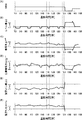
図11において、(A)は、圧延機を駆動するMRH回路のモータ速度の時間変化を示している。(B)は、レベル差ΔS(μm)の実績値の時間変化を示している。(C)は、差荷重の実績値ΔPact(Ton)の時間変化を示している。(D)は、出側差張力の実績値ΔσD act(kg/mm2)の時間変化を示している。(E)は、レベル差ΔS(μm)の計算値の時間変化を示している。(F)は、蛇行量YS(mm)の計算値の時間変化を示している。(A)〜(F)の各グラフにおいて、横軸は板材2を圧延ロール11,12間に通過させる通板時間(秒)を示している。
In FIG. 11, (A) shows the time change of the motor speed of the MRH circuit that drives the rolling mill. (B) shows the time change of the actual value of the level difference ΔS (μm). (C) has shown the time change of the track load value (DELTA) Pact (Ton) of a differential load. (D) shows the time change of the actual value Δσ D act (kg / mm 2 ) of the outlet side differential tension. (E) shows the time change of the calculated value of the level difference ΔS (μm). (F) shows the change over time of the calculated value of the meandering amount Y S (mm). In each of the graphs (A) to (F), the horizontal axis indicates the sheet passing time (seconds) for passing the
図11において、約780〜1320秒の時間帯では、グラフ(E)の通りレベル差ΔSがマイナス値となっており、WS側の圧下量がDS側の圧下量よりも大きくなっている。そして、グラフ(C)の通り差荷重ΔPactはプラス値となっており、図6に示したようにWS側の圧延荷重がDS側よりも大きくなっている。この場合、グラフ(D)のように差張力ΔσD actが一時的にマイナス値となり、図5に示したようにDS側の出側張力がWS側より大きくなっても、グラフ(F)の通り蛇行量YSは略一定となっている。つまり、図5及び図6を参照して説明したような蛇行の停留挙動が、上記計算により正確に表現されている。 In FIG. 11, in the time period of about 780 to 1320 seconds, the level difference ΔS is a negative value as shown in the graph (E), and the WS side reduction amount is larger than the DS side reduction amount. As shown in the graph (C), the differential load ΔP act is a positive value, and the rolling load on the WS side is larger than that on the DS side as shown in FIG. In this case, as shown in the graph (D), the differential tension Δσ D act temporarily becomes a negative value, and even if the DS side outlet tension becomes larger than the WS side as shown in FIG. as meandering amount Y S is substantially constant. That is, the meandering stop behavior described with reference to FIGS. 5 and 6 is accurately expressed by the above calculation.
一方、約1320〜1440秒の領域では、グラフ(C),(D)の通り差荷重ΔPact及び差張力ΔσD actがいずれもマイナス値であるため、図7及び図8に示したように圧延荷重P及び出側張力σDのいずれもDS側が大きくなっている。この場合、グラフ(F)の通り蛇行量YSがマイナス側に転じ、DS側への蛇行量が増加する。よって、図7及び図8を参照して説明したような蛇行の発散挙動も、上記計算により正確に表現されている。 On the other hand, in the region of about 1320 to 1440 seconds, the differential load ΔP act and the differential tension Δσ D act are both negative values as shown in the graphs (C) and (D), as shown in FIGS. any of the rolling load P and the exit-side tension sigma D is DS side is larger. In this case, as meandering amount Y S of the graph (F) is turned negative side, meandering amount of the DS side increases. Therefore, the meandering divergence behavior described with reference to FIGS. 7 and 8 is also accurately expressed by the above calculation.
以上のように、本実施形態では、圧延ロール11,12の差荷重ΔP及び出側差張力ΔσDに応じて変化する板材2の蛇行を正確に予測することが可能になる。これにより、オペレータが板材2のセンタリングなどの蛇行防止措置を適切なタイミングで行うことが可能となり、板材2の蛇行による圧延トラブルの発生を未然に防止することができる。
As described above, in this embodiment, it is possible to accurately predict the meandering of the
(その他実施形態)
最後に、本発明のその他実施形態について説明する。
(Other embodiments)
Finally, other embodiments of the present invention will be described.
上記実施形態1では、ヤコビアン及びその逆行列を用いて、差荷重ΔP及び差張力ΔσDに基づいて板材2の蛇行量YS及び圧延ロール11,12のレベル差ΔSを計算する方法について説明したが、これに限定されない。例えば、次のような計算方法を採用することも可能である。
In the first embodiment, the method of calculating the meandering amount Y S of the
まず、適当な蛇行量YS及びレベル差ΔSの初期値を仮定し、圧延モデルを用いて差荷重の計算値ΔPcal及び出側差張力の計算値ΔσD calをそれぞれ算出する。この圧延モデルとしては、圧延工程における物理的関係式に基づいて、ΔP、Δσ、ΔS及びYSの関係を適宜数値モデル化したものを用いることができる。 First, assuming appropriate initial values of meandering amount Y S and level difference ΔS, a calculated value ΔP cal of a differential load and a calculated value Δσ D cal of a delivery side differential tension are respectively calculated using a rolling model. As the rolling model, a model in which the relation among ΔP, Δσ, ΔS, and Y S is appropriately numerically modeled based on a physical relational expression in the rolling process can be used.
ΔPcal及びΔσD calが圧延実績であるΔPact及びΔσD actと異なる場合、その誤差が小さくなる方向にYS及びΔSを僅かだけ変化させる。そして、ΔPcal及びΔσD calを再び計算する。 When ΔP cal and Δσ D cal are different from ΔP act and Δσ D act which are actual rolling results, Y S and ΔS are slightly changed in a direction in which the error is reduced. Then, ΔP cal and Δσ D cal are calculated again.
この計算ステップを計算値(ΔPcal、ΔσD cal)と実績値(ΔPact、ΔσD act)との差が十分小さくなるまで繰り返してもよい。また、YS及びΔSを僅かだけ変化させる際、山登り法(Simplex法)等の数値計算法が用いられてもよい。 This calculation step may be repeated until the difference between the calculated values (ΔP cal , Δσ D cal ) and the actual values (ΔP act , Δσ D act ) becomes sufficiently small. Further, Y S and ΔS when which only slightly changed, numerical methods such as hill-climbing method (Simplex Method) may be used.
上記実施形態1では、タンデム式圧延機10における最上流に配置された#1スタンド10Aの圧延ロール11,12と、ステアリングロール18と、の間における板材2の蛇行を予測する場合について説明したが、これに限定されない。例えば、図12に示すように、#2スタンド10Bにおける圧延ロール11,12の差荷重ΔPと、#2スタンド10Bの出側差張力ΔσDと、に基づいて、#1〜#2スタンド間における板材2の蛇行を予測する場合に適用されてもよい。また#3以降のスタンドにおいても同様に、隣り合うスタンド間における板材2の蛇行予測に適用されてもよい。
In the first embodiment, the case where the meandering of the
上記実施形態1の蛇行予測システム1において、判定部25及び警報発生部26は必須の構成ではなく、省略されてもよい。
In the
上記実施形態1の蛇行予測方法において、少なくともΔPact及びΔσD actが圧延実績データとして入力されればよく、他の入力データとしては、hE、hD、W、P、J、σE、σDのうち一部のデータのみが用いられてもよい。 In the meandering prediction method of the first embodiment, at least ΔP act and Δσ D act may be input as rolling performance data, and other input data include h E , h D , W, P, J, σ E , σ may be only a part of the data are used of D.
上記実施形態1の蛇行予測方法では、ステップS31〜S37において入射角θが一定になるまで繰り返し計算を行う場合について説明したがこれに限定されず、繰り返し計算を行わずに次のステップS38に移行してもよい。 In the meandering prediction method of the first embodiment, the case where the calculation is repeated until the incident angle θ becomes constant in steps S31 to S37 has been described. However, the present invention is not limited to this, and the process proceeds to the next step S38 without performing the repetition calculation. May be.
上記実施形態1では、複数基のスタンドからなるタンデム式圧延機10における蛇行予測について説明したがこれに限定されず、スタンド1基のみで構成された圧延機の蛇行予測にも適用することができる。また図1に示した4重圧延機だけでなく、2重圧延機、6重圧延機又はクラスター圧延機などにおける蛇行予測にも適用することができる。また熱間圧延及び冷間圧延のいずれにおいても適用することができる。
In the said
今回開示された実施形態は、全ての点で例示であって、制限的なものではないと解されるべきである。本発明の範囲は、上記した説明ではなくて特許請求の範囲により示され、特許請求の範囲と均等の意味及び範囲内での全ての変更が含まれることが意図される。 It should be understood that the embodiments disclosed herein are illustrative and non-restrictive in every respect. The scope of the present invention is defined by the terms of the claims, rather than the description above, and is intended to include any modifications within the scope and meaning equivalent to the terms of the claims.
1 蛇行予測システム
2 板材
10 タンデム式圧延機
11,12 圧延ロール
18 ステアリングロール(上流側ロール)
21 演算部
22 受付部
23 出力部
25 判定部
26 警報発生部
J11,J12,J21,J22 ヤコビアン
J11 −1,J12 −1,J21 −1,J22 −1 逆行列
ΔPact 差荷重の実績値
ΔPcal 差荷重の計算値
ΔS レベル差
YS 蛇行量(オフセンター量)
ΔσD act 差張力の実績値
ΔσD cal 差張力の計算値
DESCRIPTION OF
21
Actual value of Δσ D act differential tension ΔCalculated value of Δσ D cal differential tension
Claims (8)
前記圧延ロールの差荷重の実績値ΔPactと、前記圧延ロールの出側における前記板材の差張力の実績値ΔσD actと、を受け付ける受付部と、
前記差荷重の計算値ΔPcalと、前記差張力の計算値ΔσD calと、を計算するための演算部と、を備え、
前記演算部は、数値モデルにより前記板材の蛇行量YS及び前記圧延ロールのレベル差ΔSを計算するように構成され、
ΔPact=ΔPcal且つΔσD act=ΔσD calの時点における前記板材の蛇行量YS及び前記圧延ロールのレベル差ΔSの計算結果を出力する出力部をさらに備えた、蛇行予測システム。 A meandering prediction system for predicting meandering of a plate material on the entry side of a pair of rolling rolls,
A receiving unit that receives the actual value ΔP act of the differential load of the rolling roll and the actual value Δσ D act of the differential tension of the plate material on the exit side of the rolling roll;
A calculation unit for calculating the calculated value ΔP cal of the differential load and the calculated value Δσ D cal of the differential tension,
The calculation unit is configured to calculate a meandering amount Y S of the plate material and a level difference ΔS of the rolling roll by a numerical model,
ΔP act = ΔP cal equipped and Δσ D act = Δσ D meandering amount of the plate at the time of cal Y S and further an output unit for outputting the calculation result of the level difference ΔS of said rolling roll, meander prediction system.
前記判定部において前記板材の蛇行量YSの時間変化が前記閾値を超えたと判定されたときに警報を発生する警報発生部と、をさらに備えた、請求項1又は2に記載の蛇行予測システム。 A determination unit for determining whether the time change of the meandering amount Y S of the plate material exceeds a predetermined threshold;
An alarm generating unit time changes in the meandering amount Y S of the plate in the evaluation unit generates an alarm when it is determined that exceeds the threshold value, further comprising a meandering prediction system according to claim 1 or 2 .
前記圧延ロールの差荷重の実績値ΔPactと、前記圧延ロールの出側における前記板材の差張力の実績値ΔσD actと、を入力するステップと、
前記差荷重の計算値ΔPcalと、前記差張力の計算値ΔσD calと、を計算するステップと、
数値モデルにより前記板材の蛇行量Ys及び前記圧延ロールのレベル差ΔSを計算するステップと、
ΔPact=ΔPcal且つΔσD act=ΔσD calの時点における前記板材の蛇行量YS及び前記圧延ロールのレベル差ΔSの計算結果を出力するステップと、を備えた、蛇行予測方法。 A meandering prediction method for predicting meandering of a plate material on the entry side of a pair of rolling rolls,
Inputting the actual value ΔP act of the differential load of the rolling roll and the actual value Δσ D act of the differential tension of the plate material on the exit side of the rolling roll;
Calculating a calculated value ΔP cal of the differential load and a calculated value Δσ D cal of the differential tension;
Calculating a meandering amount Ys of the plate material and a level difference ΔS of the rolling roll by a numerical model;
And outputting ΔP act = ΔP cal and Δσ D act = Δσ meandering amount of the plate at the time of D cal Y S and the calculation result of the level difference ΔS of said rolling rolls, with a meandering prediction method.
式(1)〜(4)のヤコビアンJ11,J12,J21,J22を計算するステップと、
前記ヤコビアンJ11,J12,J21,J22の逆行列J11 −1,J12 −1,J21 −1,J22 −1を用いて、式(5),(6)により前記板材の蛇行量YS及び前記圧延ロールのレベル差ΔSを計算するステップと、を含む、請求項5に記載の蛇行予測方法。
Calculating Jacobians J 11 , J 12 , J 21 , J 22 of equations (1)-(4);
Using the inverse matrix J 11 −1 , J 12 −1 , J 21 −1 , J 22 −1 of the Jacobian J 11 , J 12 , J 21 , J 22 , the plate material according to the formulas (5) and (6). meandering amount Y S and and calculating the level difference ΔS of said rolling roll, meandering prediction method according to claim 5.
Priority Applications (1)
| Application Number | Priority Date | Filing Date | Title |
|---|---|---|---|
| JP2016178307A JP6688706B2 (en) | 2016-09-13 | 2016-09-13 | Meandering prediction system and meandering prediction method |
Applications Claiming Priority (1)
| Application Number | Priority Date | Filing Date | Title |
|---|---|---|---|
| JP2016178307A JP6688706B2 (en) | 2016-09-13 | 2016-09-13 | Meandering prediction system and meandering prediction method |
Publications (2)
| Publication Number | Publication Date |
|---|---|
| JP2018043255A true JP2018043255A (en) | 2018-03-22 |
| JP6688706B2 JP6688706B2 (en) | 2020-04-28 |
Family
ID=61693442
Family Applications (1)
| Application Number | Title | Priority Date | Filing Date |
|---|---|---|---|
| JP2016178307A Active JP6688706B2 (en) | 2016-09-13 | 2016-09-13 | Meandering prediction system and meandering prediction method |
Country Status (1)
| Country | Link |
|---|---|
| JP (1) | JP6688706B2 (en) |
Cited By (4)
| Publication number | Priority date | Publication date | Assignee | Title |
|---|---|---|---|---|
| JP2020066050A (en) * | 2018-10-26 | 2020-04-30 | 株式会社神戸製鋼所 | Rolling mill meandering detection device and rolling mill meandering detection method |
| CN111346927A (en) * | 2020-03-03 | 2020-06-30 | 首钢京唐钢铁联合有限责任公司 | Control method for rolling force of temper mill |
| JP2020185609A (en) * | 2019-05-17 | 2020-11-19 | 株式会社神戸製鋼所 | Rolling mill meandering suppression method |
| WO2021048984A1 (en) | 2019-09-12 | 2021-03-18 | 東芝三菱電機産業システム株式会社 | System for predicting contraction |
-
2016
- 2016-09-13 JP JP2016178307A patent/JP6688706B2/en active Active
Cited By (10)
| Publication number | Priority date | Publication date | Assignee | Title |
|---|---|---|---|---|
| JP2020066050A (en) * | 2018-10-26 | 2020-04-30 | 株式会社神戸製鋼所 | Rolling mill meandering detection device and rolling mill meandering detection method |
| JP7080795B2 (en) | 2018-10-26 | 2022-06-06 | 株式会社神戸製鋼所 | Meander detection device for rolling mills and meander detection method for rolling mills |
| JP2020185609A (en) * | 2019-05-17 | 2020-11-19 | 株式会社神戸製鋼所 | Rolling mill meandering suppression method |
| JP7191765B2 (en) | 2019-05-17 | 2022-12-19 | 株式会社神戸製鋼所 | Rolling mill meandering suppression method |
| WO2021048984A1 (en) | 2019-09-12 | 2021-03-18 | 東芝三菱電機産業システム株式会社 | System for predicting contraction |
| KR20210046738A (en) | 2019-09-12 | 2021-04-28 | 도시바 미쓰비시덴키 산교시스템 가부시키가이샤 | Tightening occurrence prediction system |
| CN112839746A (en) * | 2019-09-12 | 2021-05-25 | 东芝三菱电机产业系统株式会社 | Fold generation prediction system |
| CN112839746B (en) * | 2019-09-12 | 2022-10-11 | 东芝三菱电机产业系统株式会社 | Fold generation prediction system |
| EP3838432B1 (en) * | 2019-09-12 | 2023-01-04 | Toshiba Mitsubishi-Electric Industrial Systems Corporation | System for predicting contraction |
| CN111346927A (en) * | 2020-03-03 | 2020-06-30 | 首钢京唐钢铁联合有限责任公司 | Control method for rolling force of temper mill |
Also Published As
| Publication number | Publication date |
|---|---|
| JP6688706B2 (en) | 2020-04-28 |
Similar Documents
| Publication | Publication Date | Title |
|---|---|---|
| JP6688706B2 (en) | Meandering prediction system and meandering prediction method | |
| JP4962334B2 (en) | Rolling mill control method | |
| JP4214150B2 (en) | Rolling method and rolling apparatus for metal sheet | |
| JP4988171B2 (en) | Rolling mill control device | |
| JP5790636B2 (en) | Rolled material meander control method, rolled material meander control device, rolled material meander control program, and rolled material manufacturing method | |
| JP5734112B2 (en) | Thickness control method in rolling mill | |
| JP4903676B2 (en) | Rolling method and rolling apparatus for metal sheet | |
| JP4267609B2 (en) | Rolling method and rolling apparatus for metal sheet | |
| JP6688727B2 (en) | Meandering prediction system, meandering prediction method, and rolling mill operator support method | |
| JP6324259B2 (en) | Rolling control device, rolling control method, and rolling control program | |
| JP4214099B2 (en) | Rolling method and rolling apparatus for metal sheet | |
| JP2007061876A (en) | Method for controlling thickness in cold tandem rolling | |
| CN113710386B (en) | Method for controlling meandering of rolled material | |
| JP4306273B2 (en) | Strip meander control device and meander control method for tandem rolling mill | |
| JP6031344B2 (en) | Rolling control device, rolling control method, and rolling control program | |
| JP4288888B2 (en) | Strip meander control device and meander control method for tandem rolling mill | |
| JP4214069B2 (en) | Rolling method and rolling apparatus for metal sheet | |
| JP2006122980A (en) | Method for predicting deformation resistance of rolling material and frictional coefficient between roll and rolling material in tandem cold rolling mill, and tandem cold rolling method | |
| JP6057774B2 (en) | Identification method of mill elongation formula in rolling mill | |
| JP6760252B2 (en) | Roller control device and control method | |
| JP2009034730A (en) | Tension control device for tandem rolling mill | |
| JP2004050217A (en) | Tension controller for tandem rolling mill | |
| JP4564438B2 (en) | Steel sheet elongation measuring apparatus and elongation measuring method | |
| JP2002210512A (en) | Method for setting screw-down location in sheet rolling | |
| JP3583835B2 (en) | Setup method in hot finish rolling |
Legal Events
| Date | Code | Title | Description |
|---|---|---|---|
| A621 | Written request for application examination |
Free format text: JAPANESE INTERMEDIATE CODE: A621 Effective date: 20181203 |
|
| A977 | Report on retrieval |
Free format text: JAPANESE INTERMEDIATE CODE: A971007 Effective date: 20190919 |
|
| A131 | Notification of reasons for refusal |
Free format text: JAPANESE INTERMEDIATE CODE: A131 Effective date: 20191023 |
|
| A521 | Written amendment |
Free format text: JAPANESE INTERMEDIATE CODE: A523 Effective date: 20191204 |
|
| A131 | Notification of reasons for refusal |
Free format text: JAPANESE INTERMEDIATE CODE: A131 Effective date: 20200107 |
|
| A521 | Written amendment |
Free format text: JAPANESE INTERMEDIATE CODE: A523 Effective date: 20200124 |
|
| TRDD | Decision of grant or rejection written | ||
| A01 | Written decision to grant a patent or to grant a registration (utility model) |
Free format text: JAPANESE INTERMEDIATE CODE: A01 Effective date: 20200331 |
|
| A61 | First payment of annual fees (during grant procedure) |
Free format text: JAPANESE INTERMEDIATE CODE: A61 Effective date: 20200406 |
|
| R150 | Certificate of patent or registration of utility model |
Ref document number: 6688706 Country of ref document: JP Free format text: JAPANESE INTERMEDIATE CODE: R150 |