JP2017538470A - X-ray flux reducer for photon counting detector - Google Patents
X-ray flux reducer for photon counting detector Download PDFInfo
- Publication number
- JP2017538470A JP2017538470A JP2017525971A JP2017525971A JP2017538470A JP 2017538470 A JP2017538470 A JP 2017538470A JP 2017525971 A JP2017525971 A JP 2017525971A JP 2017525971 A JP2017525971 A JP 2017525971A JP 2017538470 A JP2017538470 A JP 2017538470A
- Authority
- JP
- Japan
- Prior art keywords
- radiation
- filter device
- flux
- rigid
- flux filter
- Prior art date
- Legal status (The legal status is an assumption and is not a legal conclusion. Google has not performed a legal analysis and makes no representation as to the accuracy of the status listed.)
- Granted
Links
Images


Classifications
-
- A—HUMAN NECESSITIES
- A61—MEDICAL OR VETERINARY SCIENCE; HYGIENE
- A61B—DIAGNOSIS; SURGERY; IDENTIFICATION
- A61B6/00—Apparatus for radiation diagnosis, e.g. combined with radiation therapy equipment
- A61B6/02—Devices for diagnosis sequentially in different planes; Stereoscopic radiation diagnosis
- A61B6/03—Computerised tomographs
- A61B6/032—Transmission computed tomography [CT]
- A61B6/035—Mechanical aspects of CT
-
- A—HUMAN NECESSITIES
- A61—MEDICAL OR VETERINARY SCIENCE; HYGIENE
- A61B—DIAGNOSIS; SURGERY; IDENTIFICATION
- A61B6/00—Apparatus for radiation diagnosis, e.g. combined with radiation therapy equipment
- A61B6/04—Positioning of patients; Tiltable beds or the like
- A61B6/0407—Supports, e.g. tables or beds, for the body or parts of the body
-
- A—HUMAN NECESSITIES
- A61—MEDICAL OR VETERINARY SCIENCE; HYGIENE
- A61B—DIAGNOSIS; SURGERY; IDENTIFICATION
- A61B6/00—Apparatus for radiation diagnosis, e.g. combined with radiation therapy equipment
- A61B6/06—Diaphragms
-
- A—HUMAN NECESSITIES
- A61—MEDICAL OR VETERINARY SCIENCE; HYGIENE
- A61B—DIAGNOSIS; SURGERY; IDENTIFICATION
- A61B6/00—Apparatus for radiation diagnosis, e.g. combined with radiation therapy equipment
- A61B6/42—Apparatus for radiation diagnosis, e.g. combined with radiation therapy equipment with arrangements for detecting radiation specially adapted for radiation diagnosis
- A61B6/4208—Apparatus for radiation diagnosis, e.g. combined with radiation therapy equipment with arrangements for detecting radiation specially adapted for radiation diagnosis characterised by using a particular type of detector
- A61B6/4241—Apparatus for radiation diagnosis, e.g. combined with radiation therapy equipment with arrangements for detecting radiation specially adapted for radiation diagnosis characterised by using a particular type of detector using energy resolving detectors, e.g. photon counting
Abstract
イメージングシステムは、検査領域106のまわりを回転して、検査領域を横切る放射線を放出するように構成される放射線源108を含む。イメージングシステムは、検査領域を横切る放射線を検出して、検出される放射線を示す信号を出力するように構成される放射線感受性ピクセル112のアレイを更に含む。放射線感受性ピクセルのアレイは、検査領域の間に、放射線源に対向して配置される。 イメージングシステムは、放射線源及びフォトンカウンティングピクセルの放射線感受性検出器アレイの間の検査領域に配置されるリジッドフラックスフィルタ装置130を更に含む。リジッドフラックスフィルタ装置は、検査領域を横切る放射線及びそれに関する入射をフィルタリングするように構成される。 リジッドフラックスフィルタ装置を離れる放射線は、所定のフラックスを有する。The imaging system includes a radiation source 108 that is configured to rotate about the examination region 106 to emit radiation across the examination region. The imaging system further includes an array of radiation sensitive pixels 112 configured to detect radiation across the examination region and output a signal indicative of the detected radiation. An array of radiation sensitive pixels is disposed between the examination regions and facing the radiation source. The imaging system further includes a rigid flux filter device 130 disposed in the examination region between the radiation source and the radiation sensitive detector array of photon counting pixels. The rigid flux filter device is configured to filter radiation and associated incidents across the examination region. The radiation leaving the rigid flux filter device has a predetermined flux.
Description
以下は、概してイメージングシステムのフォトンカウンティング検出器のX線フラックス入力を制御することに関し、コンピューター断層撮影(CT)への特定の適用で記述される。 しかしながら、以下はフラットパネル、X線、放射線療法及び/又はその他のイメージングアプリケーションにも適用可能である。 The following will be described with specific application to computed tomography (CT), generally relating to controlling the x-ray flux input of a photon counting detector of an imaging system. However, the following is also applicable to flat panel, x-ray, radiation therapy and / or other imaging applications.
コンピューター断層撮影スキャナは、X線ビームを放出するX線管を含む。 X線ビームの一部は検査領域の視野に位置される被験体又は対象物を横切って、被験体又は対象物の放射密度の関数として減衰される。 X線ビームの他のサブ部分は、被験体又は対象物を横切ることなく、検査領域の視野を横切る。 検出器アレイは視野を横切る放射線を検出して、それを示す信号を生成する。 再構成器は信号を再構成し、ボリュメトリック画像データを生成する。 The computed tomography scanner includes an x-ray tube that emits an x-ray beam. A portion of the x-ray beam is attenuated as a function of the radiation density of the subject or object across the subject or object located in the field of view of the examination area. Other sub-portions of the x-ray beam traverse the field of view of the examination area without traversing the subject or object. The detector array detects radiation across the field of view and generates a signal indicative thereof. The reconstructor reconstructs the signal and generates volumetric image data.
ビームシェーパーは、X線管及び検査領域の間でX線ビームのパスに位置決めされる。ビームシェーパーは、その概略的な物理的な形状がボウタイに似ているのでボウタイフィルタと称される。ビームシェーパーはビームを、ビームの周辺より大幅に減衰させるように形成される。これにより、ビームシェーパーは、より高いフラックスレートで不十分なカウントレート性能を被る、直接変換フォトンカウンティング検出器に関連して、周辺におけるフラックスを減衰させるのに非常に適している。 The beam shaper is positioned in the path of the X-ray beam between the X-ray tube and the examination area. A beam shaper is called a bow tie filter because its schematic physical shape resembles a bow tie. The beam shaper is formed to attenuate the beam significantly from the periphery of the beam. This makes the beam shaper very suitable for attenuating flux in the vicinity in connection with direct conversion photon counting detectors that suffer from poor count rate performance at higher flux rates.
残念なことに、減衰構造(例えば、足の間のスペース)の間にゼロ(又は低)減衰構造を備える被験体の部分(例えば、足と腕のような四肢)又は対象物のため、ビームシェーパーは、直接変換フォトンカウンティング検出器にとってあまり適切でない。 これは、たとえば、ビームシェーパーが、このより中央の領域においてフラックスを十分に減らさないからである。 その結果、検出器アレイのいくらか中央に位置される検出器要素は、過度のフラックスを受け、検出し、再構成されるボリュメトリック画像データにおける画質は低下させられ得る。 Unfortunately, for parts of the subject (eg, extremities such as legs and arms) or objects with zero (or low) attenuation structure between the dampening structures (eg, the space between the legs), the beam Shapers are less suitable for direct conversion photon counting detectors. This is because, for example, the beam shaper does not reduce the flux sufficiently in this more central region. As a result, detector elements located in the middle of the detector array may experience excessive flux, detect, and reduce the image quality in volumetric image data that is reconstructed.
これは、ギャップ1006によって分離される対象物1002及び1004に関連して、図10において理解されることができる。 図10において、放出されるビーム1008は、周辺領域1012でより厚く、中央領域1014でより薄く、ビームシェーパー1010によってフィルタリングされ、周辺領域1018においてより大きく、中央領域1020においてより小さくフィルタリングされるフィルタビーム1016が生成される。 ギャップ1006に近い検出器アレイ1024の領域1022は、過度のフラックスを受ける検出器アレイ1024の領域を表す。
This can be seen in FIG. 10 in connection with
一つの態様において、イメージングシステムは、検査領域のまわりを回転して、検査領域を横切る放射線を放出するように構成される放射線源を含む。 イメージングシステムは、検査領域を横切る放射線を検出して、検出される放射線を示す信号を出力するように構成される放射線感受性ピクセルのアレイを更に含む。放射線感受性ピクセルのアレイは、検査領域の間に、放射線源に対向して配置される。 イメージングシステムは、放射線源及び放射線感受性検出器アレイの間の検査領域に配置されるリジッドフラックスフィルタ装置を更に含む。リジッドフラックスフィルタ装置は、検査領域を横切る放射線及びそれに関する入射をフィルタリングするように構成される。 リジッドフラックスフィルタ装置を離れる放射線は、所定のフラックスを有する。 In one embodiment, the imaging system includes a radiation source configured to rotate around the examination region and emit radiation across the examination region. The imaging system further includes an array of radiation sensitive pixels configured to detect radiation across the examination region and output a signal indicative of the detected radiation. An array of radiation sensitive pixels is disposed between the examination regions and facing the radiation source. The imaging system further includes a rigid flux filter device disposed in the examination region between the radiation source and the radiation sensitive detector array. The rigid flux filter device is configured to filter radiation and associated incidents across the examination region. The radiation leaving the rigid flux filter device has a predetermined flux.
他の態様において、本方法は検査領域のまわりで放射線源を回転させるステップを含む。 放射線源は、検査領域を横切る放射線を放出する。 本方法は、検査領域に配置されるリジッドフラックスフィルタ装置で検査領域を横切る放射線をフィルタリングするステップを更に含む。 本方法は、放射線源に対向して位置される検出器ピクセルを用いて、検査領域の向かいで、リジッドフラックスフィルタ装置を横切る放射線を検出し、それを示す信号を生成するステップを更に含む。 In other embodiments, the method includes rotating the radiation source around the examination region. The radiation source emits radiation that traverses the examination area. The method further includes filtering radiation across the examination region with a rigid flux filter device disposed in the examination region. The method further includes detecting radiation across the rigid flux filter device, opposite the examination region, using a detector pixel located opposite the radiation source and generating a signal indicative thereof.
さらに他の態様において、リジッドフラックスフィルタ装置は放射線源及びフォトンカウンティングピクセルの放射線感受性検出器アレイの間の検査領域に配置されるように構成され、リジッドフラックスフィルタ装置は、検査領域を横切る放射線及びそれに関する入射をフィルタリングするように構成され、 リジッドフラックスフィルタ装置を離れる放射線は所定のフラックスを有する。リジッドフラックスフィルタ装置は、ポリテトラフルオロエチレン材又はアルミニウムの少なくとも一つを含み、所与の放射線源電圧及び所与の放射線源電流に対応する厚みを有する。 In yet another aspect, the rigid flux filter device is configured to be disposed in an examination region between the radiation source and the radiation sensitive detector array of photon counting pixels, the rigid flux filter device comprising radiation that crosses the examination region and And the radiation leaving the rigid flux filter device has a predetermined flux. The rigid flux filter device includes at least one of a polytetrafluoroethylene material or aluminum and has a thickness corresponding to a given radiation source voltage and a given radiation source current.
本発明は、様々なコンポーネント及びコンポーネントの構成、並びに様々なステップ及びステップの構成の形状を取り得る。図面は好ましい実施形態を例示するためのものに過ぎず、本発明を限定するものとして解釈すべきではない。 The invention may take form in various components and arrangements of components, and in various steps and arrangements of steps. The drawings are only for purposes of illustrating the preferred embodiments and are not to be construed as limiting the invention.
図1は、コンピューター断層撮影(CT)スキャナのようなイメージングシステム例100を図示する。 イメージングシステム100は、回転ガントリ102及び静止ガントリ104を含む。 回転ガントリ102は、静止ガントリ104によって回転可能に支持される。 回転ガントリ102は、長手方向又はz軸について検査領域106のまわりを回転するように構成される。
FIG. 1 illustrates an
イメージングシステム100は、回転ガントリ102によって回転可能に支持されるX線管のような放射線源108を更に含む。 放射線源108は検査領域106のまわりで回転ガントリ102により回転し、検査領域106を横切る放射線を放出するように構成される。 イメージングシステム100は、放射線源コントローラ110を更に含む。 放射線源コントローラ110は、放射線放出を調整するように構成される。 このために、放射線コントローラ110はカソードの加熱電流、放射線源108に供給される電圧を変え、電子が流れることを可能にするか、又は抑制するグリッドスイッチを制御し、放射線ビームに、及び放射線ビームから物理フィルタを動かすこと等ができる。
The
イメージングシステム100は、ビームシェーパー109を更に含む。 ビームシェーパー109は、放射線源108及び検査領域106の間でX線ビームのパスに配置される。 ビームシェーパー109は、ビームを、ビームの周辺においてより大幅に減衰させるように形成される。これにより、ビームシェーパーは、より高いフラックスレートで不十分なカウントレート性能を被る、直接変換フォトンカウンティング検出器に関連して、周辺におけるフラックスを減衰させるのに非常に適している。ビームシェーパー109の例は、ボウタイに似ている形状を有するボウタイフィルタである。
The
イメージングシステム100は、z軸方向に沿って構成される放射線感受性ピクセル112のアレイを更に含む。 ピクセル112は、検査領域106の間に、放射線源108に対向して位置され、検査領域106を横切る放射線を検出して、検出される放射線を示す信号を生成する。図の例において、ピクセル112は直接変換フォトンカウンティング検出器ピクセルを含む。 このようなピクセルにより、生成される信号は、検出フォトンのエネルギーを示すピーク振幅又はピーク高さを有する電流又は電圧を含む。 直接変換フォトンカウンティング検出器ピクセルは、CdTe、CdZnTe、Si、Ge、GaAsのような何れかの適切な直接変換物質又は他の直接変換物質を含む。
The
イメージングシステム100は、検出器ピクセル112によって出力される電気信号を処理して、検出フォトンのエネルギーを示す電圧のようなパルス又は他のパルスを生成する、パルスシェーパー114を更に含む。。イメージングシステム100は、パルスをエネルギー識別するエネルギー識別器116をさらに含む。 図の例において、エネルギー識別器116はパルスの振幅を関心エネルギーに対応する少なくとも一つのエネルギー閾値と比較する少なくとも一つのコンパレーター118を含む。 コンパレーター118は、検出フォトンのエネルギーが閾値の上又は下にあるかを示す出力信号を生成する。
The
イメージングシステム100は、各々の閾値のためのカウント値をインクリメント(又はディクリメント)するカウンター120を更に含む。たとえば、特定の閾値のためのコンパレーター118の出力が、パルスの振幅は対応する閾値を上回ることを示すとき、その閾値のためのカウント値はインクリメントされる。イメージングシステム100はカウントされるパルスを、異なるエネルギー範囲に対応するエネルギービンに割り当てるビナー122を更に含む。 たとえば、ビンは2つの閾値の間でエネルギー範囲のために規定される。 この例の場合、ビナー122は、より高い閾値のためでなく、より低い閾値のためにカウントをもたらすフォトンを、2つの閾値の間のエネルギー範囲のために規定されるビンに割り当てる。
The
イメージングシステム100は、スペクトル及び/又は従来の再構成アルゴリズムを使用してビニングされるデータを再構成して、スペクトル及び/又は従来のボリュメトリック画像データを生成する再構成器124を更に含む。 イメージングシステム100は、オペレーターコンソール126として用いられる計算システムを更に含み、ディスプレイのような出力装置及びキーボード、マウス等のような入力デバイスを含む。 コンソール126の常駐ソフトウェアはシステム100の動作を制御し、選択スキャンプロトコルに応じて管電流の変調を制御する。
The
イメージングシステム100は、ベース132及びテーブルトップ134を備える被験体支持部128を更に含む。テーブルトップ134は、ベース132に可動に取り付けられ、患者ローディング、患者スキャン及び患者アンローディングのためのスキャンの前、その間、及びその後に、検査領域106に、及びそれから水平に並進するように構成される。ベース132は検査部屋のフロア136に取り付けられるか、又はそれに置かれる。 ベース132は、上下に垂直に動き、それゆえに、たとえば、患者をローディング及びアンローディングするため、並びにたとえばスキャンされるべき領域に基づいてスキャン視野のアイソセンターをスキャンするように適切な高さに患者を位置決めするためにテーブルトップ134を上下に動かすように構成される。
The
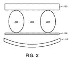
減衰構造の間でゼロ構造又は低減衰構造を含む対象物又は被験体の一部をスキャンするためのフラックスフィルタ装置130が提供される。このようなスキャンのために、フラックスフィルタ装置130は、フラックスフィルタ装置130に出力される放射線及び検出器ピクセルの内部領域への入射の所定のフラックス範囲におけるフラックスを有するように、(ゼロ構造又は低減衰構造に対応する)放射線感受性ピクセルのアレイの検出器ピクセルの内部領域の方へ横切る放射線を少なくとも減衰させるように構成される。通常、フラックスフィルタ装置130は、放射線ビームの間の放射線を均一に減衰させるように構成される。
A
図2、3、4、5、6、7及び8によれば、フラックスフィルタ装置130の非限定的な例が図示される。
2, 3, 4, 5, 6, 7, and 8, non-limiting examples of
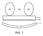
図2は、フラックスフィルタ装置130が、構造202及び204の間にエアギャップ206を備える構造202及び204(例えば、足)に位置されて、置かれる実施例を示す。この例において、フィルタ装置130は、構造202及び204とエアギャップ206との間で均一に放射線を減衰させる。図3も、フラックスフィルタ装置130が、構造202及び204の間にエアギャップ206を備える構造202及び204に位置されて、置かれる実施例を示す。しかしながら、この例において、フィルタ装置130は、過度のフラックスが検出器アレイ112及び軽くだけ放射線を減衰させる外部領域302に達することを防ぐためにエアギャップ206を横切る放射線を減衰させる内部領域300を含む。
FIG. 2 shows an embodiment in which the
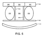
フラックスフィルタ装置130が、被験体支持部128に置かれ、構造202及び204並びにその間のエアギャップ206に渡ってフィルタ部分400を有するように構成されるフィルタ部分400並びにブラケット402及び404を含むこと以外、図4は図2と類似している。ブラケット402及び404は細長くてリジッドであり、X線放射線を軽くだけ減衰させる物質を含む。 フラックスフィルタ装置130が、構造202及び204並びにその間のエアギャップ206に渡って内部及び外部部分300及び302を保持するブラケット502及び504を含むこと以外、図5は図3と類似している。同様に、ブラケット502及び504は、X線放射線を軽くだけ減衰させる物質を含む。
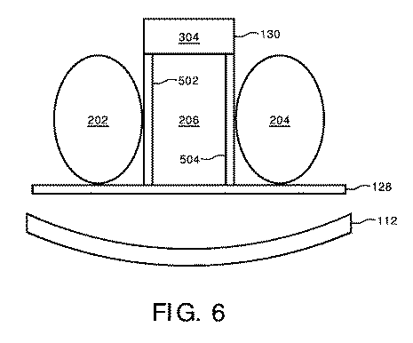
フラックスフィルタ装置130が外部部分302を含まない以外、図6は図5と類似している。図4-6に示される構成に関して、フラックスフィルタ装置130はブラケット402、404、502若しくは504の一つだけ、又はブラケット402、404、502若しくは504の二つより多くを含むことは評価される。 さらに、ブラケット402、404、502又は504の一つ又はそれより多くは延在可能なように構成され、スキャンされる対象物のサイズに基づくフラックスフィルタ装置130の高さの調整を可能にする。延在可能なブラケット例は、伸縮部材、ベース部材及びベース部材に付けられる一つ又はそれより多くの伸縮部材、交換可能で異なるサイズのブラケットのセット等を含む。
FIG. 6 is similar to FIG. 5 except that the
図7は、図2のフラックスフィルタ装置130が構造202及び204並びに構造202及び204の間のエアギャップ206の下に位置される例を示す。
FIG. 7 shows an example in which the
続けて図1-7を参照すると、一つの例において、フラックスフィルタ装置130は、曲がらなくて、位置される対象物の形状に適合しないという点でリジッド構造である。むしろ、フラックスフィルタ装置130は、対象物の形状に関係なく、その形状を維持する。図示のフラックスフィルタ装置130は、非減衰放射線又は低減衰放射線を受けるフォトンカウンティング検出器ピクセル112が飽和しないように、放射線を減衰させる物質を含む。図示のフラックスフィルタ装置130は、光電吸収及びコンプトン散乱によって放射線を減衰させる物質を含む。好適な物質は、水又は通常の軟組織より相対的により高い光電吸収を有する、高い原子量、Z、(例えば、Z≧13)物質を含む。
With continued reference to FIGS. 1-7, in one example, the
通常、フラックスフィルタ装置130は、光電吸収及びビームハードニングの間の所定の妥協点を提供する。 このような物質の例は、テトラフルオロエチレン、アルミニウム(Al)等の合成フッ素重合体であるポリテトラフルオロエチレン(PTFE)を含む。 適切なPTFE材の例は,
デュポン社(USA)の製品であるTeflon(R)である。
Typically, the
Teflon (R), a product of DuPont (USA).
フラックスフィルタ装置130の厚みは、管電圧(V)、管電流(I)、ビームコンディショナー(例えば、プレ患者フィルタ)セッティング(B)のようなスキャンプロトコルパラメータに依存する。 中央検出器ピクセルの最大フラックスは、スキャナの理論的な物理モデル又は較正プロシージャによる関数F(V,B,I)に基づいて推定されることができる。後者の場合、中央検出器のフラックスFCalib(V,B,ICalib)は、すべての可能なV及びBセッティング並びに一つの電流(Icalib)のために測られる。 スキャンプロトコルパラメータFScan,BScan,IScanによるスキャンのための検出器のFMaxの最大フラックスのために、フラックスフィルタ装置130は、
フラックスフィルタ装置130のセットは、スキャンプロトコルパラメータFScan,BScan,IScanの一つ又はそれより多くの異なる組合せのために生成されることができる。スキャンのための特定のフラックスフィルタ装置130はそれから、スキャンプロトコルパラメータFScan,BScan,IScanの一つ又はそれより多くの異なる組合せのためのフラックスフィルタ装置130を含むフラックスフィルタ装置130のセットから臨床医によって選ばれることができる。一つの例において、ユーザーはプロトコルを選び、コンソール126はプロトコルのための適切なフラックスフィルタ装置130を特定する情報を提示する。フラックスフィルタ装置130は、構造及び構造の間のゼロ又は低減衰領域の何れかをカバーするために、構成に依存して、対象物又は被験体(図2)上に位置されることができ、又は構造及び構造の間のゼロ又は低減衰領域の何れかをカバーするために、被験体支持部128(図3)上に位置されることができる。
A set of
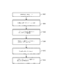
図8は、ここに記述される実施例による方法を例示する。 FIG. 8 illustrates a method according to the embodiments described herein.
以下の行為の順序は例示を意図するものであり限定的ではないことを理解すべきである。そのため、他の順序も本明細書で予期される。加えて、一つ若しくは複数の行為が省略され且つ/又は一つ若しくは複数の追加の行為が含められても良い。 It should be understood that the following sequence of actions is intended to be illustrative and not limiting. As such, other orders are also contemplated herein. In addition, one or more actions may be omitted and / or one or more additional actions may be included.
802において、対象物又は被験体は、被験体支持部にローディングされる。 At 802, an object or subject is loaded onto a subject support.
804において、スキャンプロトコルは、コンソールで選ばれる。 At 804, the scan protocol is selected at the console.
806において、フラックスフィルタ装置は、スキャンプロトコルパラメータ及び対象物又は被験体に基づいて選ばれる。 At 806, a flux filter device is selected based on the scan protocol parameters and the object or subject.
808において、選択フラックスフィルタ装置は、対象物又は被験体上、又はそれに渡って位置される。 At 808, the selective flux filter device is located on or across the object or subject.
810において、スキャンは実行される。 At 810, a scan is performed.
812において、投影データは、ボリュメトリック画像データを生成するように再構成される。 At 812, the projection data is reconstructed to generate volumetric image data.
図9は、ここに記述される実施例による他の方法を例示する。 この例において、被験体は人間又は動物の患者であり、フラックスフィルタ装置130は、例えば図2-6に示されるように、患者がフラックスフィルタ装置130及び被験体支持部128の間にいるように位置される。
FIG. 9 illustrates another method according to embodiments described herein. In this example, the subject is a human or animal patient, and the
以下の行為の順序は例示を意図するものであり限定的ではないことを理解すべきである。そのため、他の順序も本明細書で予期される。加えて、一つ若しくは複数の行為が省略され且つ/又は一つ若しくは複数の追加の行為が含められても良い。 It should be understood that the following sequence of actions is intended to be illustrative and not limiting. As such, other orders are also contemplated herein. In addition, one or more actions may be omitted and / or one or more additional actions may be included.
902において、患者は被験体支持部128の上に位置される。
At 902, the patient is positioned on the
904において、スキャンプロトコルは、コンソール126で選ばれる。 この例において、選択スキャンプロトコルにより、放射線源コントローラ110は、少なくとも、第一のフラックス及び第二の異なるフラックスの間の放射線放出を変調する変調パターンで放射線放出を変調する。次に記述されるように、このような変調は放射線源108角に依存する。
At 904, a scan protocol is selected at
たとえば、一つの変調パターンにより、コントローラ110は、放射線源108が検査領域106に配置される被験体支持部の部分下にある6時位置を通じて、3時位置から9時位置まで(又はシステムが反時計回りに回転する場合、6時位置を通じて、9時位置から3時位置まで)放射線源が回転しているとき、フラックスがより低くなるように、放射線放出を変調する。
For example, with one modulation pattern, the
さらに、この変調パターンにより、コントローラ110は、放射線源108が検査領域106に配置される被験体支持部の部分に対向する12時位置を通じて、9時位置から3時位置まで(又は12時位置を通じて、3時位置から9時位置まで)放射線源が回転しているとき、フラックスがより高くなるように、放射線放出を変調する。
Furthermore, this modulation pattern allows the
フラックスは、放射線源108のカソードで加熱電流を制御するステップを通じて変調されることができる。 他の例において、2つのフラックスのより低い方は、例えば、検査領域106を横切る放射線を妨げるための、グリッドスイッチ、物理フィルタなどを使っているゼロフラックスである。
The flux can be modulated through controlling the heating current at the cathode of the
906において、フラックスフィルタ装置130は、スキャンプロトコルパラメータに基づいてフラックスフィルタ装置130のセットから選ばれる。
At 906, the
908において、ここに及び/又は他で記述されるように、選択フラックスフィルタ装置130は患者の上に、又はそれに渡って位置される。
At 908, the selective
910において、患者は変調パターンを使ってスキャンされる。 At 910, the patient is scanned using the modulation pattern.
たとえば、スキャンの間、放射線源コントローラ110は、放射線源が6時位置を通じて、3時位置から9時位置まで(又は反時計回りの場合、6時位置を通じて、9時位置から3時位置まで)放射線源が回転しているとき、フラックスがより低いフラックスになるように、及び放射線源が12時位置を通じて、9時位置から3時位置まで(又は反時計回りの場合、12時位置を通じて、3時位置から9時位置まで)放射線源が回転しているとき、フラックスがより高くなるように、放射線放出を変調する。
For example, during a scan, the
912において、投影データは、ボリュメトリック画像データを生成するように再構成される。 At 912, the projection data is reconfigured to generate volumetric image data.
図9において、フィルタ装置130は、図2-6で示されるようにフィルタ装置130及び被験体支持部128の間に対象物202及び204を備える被験体支持部128に対向して位置される。図7で示されるように、 フィルタ装置130が対象物202及び204並びに被験体支持部128の間に位置される実施例において、12時位置を通じて、9時位置から3時位置まで放射線源が回転するとき、フラックスがより低いレベルになるように、及び6時位置を通じて、3時位置から9時位置まで放射線源が回転するとき、フラックスがより高いフラックスになるように、フラックスは変調される。概して、患者の前の何れかの減衰がX線ドーズの低減を示唆するが、後の減衰はドーズの浪費を示唆するため、それが後よりも患者を通過する前にフラックスを減衰させるように、利用される特定の変調パターンは選ばれる。
In FIG. 9, the
より詳しくは、このように放射線放出を変調することによって、放射線が患者を横切る前にフィルタリングされる位置に対して、対象物又は被験体を横切る放射線が後続してフィルタリングされる位置に放射線源108がある間、患者への放射線ドーズは低減される。放射線が患者を横切る前にフィルタリングされる位置に放射線源108がある場合、検出器によって観測されるフラックスは低減され、患者ドーズは低くなる。対象物又は被験体を横切る放射線が後続してフィルタリングされる位置に放射線源108がある場合、検出器によって観測されるフラックスは患者ドーズの低減なしに低減され、患者を横切るX線がフィルタリングされ、ボリュメトリック画像データの生成に寄与しない点で浪費されるドーズがもたらされる。
More specifically, by modulating the radiation emission in this manner, the
上記の変調パターンはこのドーズ非効率性を低減し、ボリュメトリック画像データを生成するために利用されない患者に対するドーズを含む。 The modulation pattern described above reduces this dose inefficiency and includes doses for patients that are not utilized to generate volumetric image data.
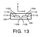
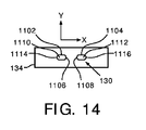
図 11-14は、フラックスフィルタ装置130がテーブルトップ134内、又はその内側に取り外し可能に設置される実施例を例示する。図11は、フラックスフィルタ装置130の斜視図を示す。 図12は、フラックスフィルタ装置130の上面図を示す。 図13は、図12の線A-Aに沿うフラックスフィルタ装置130の第一の断面図を示す。 図14は、図12の線B-Bに沿う、フラックスフィルタ装置130の第二の断面図を示す。
FIGS. 11-14 illustrate an embodiment in which the
フラックスフィルタ装置130は、一つ又はそれより多くのフラックス低減要素を含む。 明確性及び簡潔性のために、2つのフラックス低減要素1102及び1104はこの例で示される。各々のフラックス低減要素1102(又は1104)は、z軸に沿って延在する第一の側1106(又は1108)、第一の側1106(又は1108)から垂直なx軸に沿って延在する第二の側1110(又は1112)、第一及び第二の側1106(又は1108)及び1110(又は1112)の交差部で形成される直角に対向する第3の側1114(又は1116)を備える直角三角形の形状を有する。他の形状もここに考えられる。
The
フラックス低減要素1102及び1104は、互いに対向する第一の側1106及び1108でx/z平面において互いに対してテーブルトップ134のキャビティにおいてアラインされる。一つ又はそれより多くのフラックス低減要素1102及び1104の位置は、マニュアルで、並びに/又はx及び/若しくはz方向に外部制御によって調節可能である。スカウト及び/又は他のスキャンに基づいて、一つ又はそれより多くのフラックス低減要素1102及び1104は、それらがX線吸収物質を低吸収及び/又はゼロ吸収を伴う領域に加えるように位置される。
The
図15は、一つ又はそれより多くのフラックス低減要素1102及び1104が患者1506の肺1504を横切る(すなわち、低吸収)X線1502を減衰する例を図示する。図16は、一つ又はそれより多くのフラックス低減要素1102及び1104が患者1608の脚部1606(すなわち、ゼロ吸収)及び/又は足1606の内部周辺部1610(すなわち、低吸収)の間の空のスペース1604を横切るX線1602を減衰する例を図示する。患者1506及び1608のより高い減衰部分を横切るX線は、明確性のために示されない。
FIG. 15 illustrates an example in which one or more
胸部及び下肢の少なくとも一つのサブ部分をカバーしているスキャンのために、一つ又はそれより多くのフラックス低減要素1102及び1104は、肺(図15)をスキャンするために一つ又はそれより多くのフラックス低減要素1102及び1104の間の非ゼロギャップ1508がある位置から一つ又はそれより多くのフラックス低減要素1102及び1104が隣接して、下肢(図16)をスキャンするために足の間の領域を吸収する連続しているさらなるX線を形成する異なる位置まで少なくともx-方向に動かされる。運動は連続的になり得るか、別々になり得る。 スキャンの間、フラックス低減装置130を動かすことはz-方向における大きな範囲でのスキャンによく適しているが、フラックス低減要素1102及び1104が低吸収の領域をこのような運動なしで完全にカバーしない。 さもなければ、フラックス低減要素1102及び1104は、テーブルトップ134に対して静止したままである。
For scans covering at least one sub-part of the chest and lower limbs, one or more
図11-16において、フラックスフィルタ装置130は、第一の側1106及び1108が回転ガントリ104の近位にあるように設置される。患者が、回転ガントリ104に対して自身の頭を近位にして、自身の足を遠位にしてテーブルトップ134上に横になるこの構成はよく適している。 バリエーションにおいて、フラックスフィルタ装置130は、第一の側1106及び1108が回転ガントリ104に対して遠位になるように設置される。患者が、回転ガントリ104に対して自身の頭を遠位にして、自身の足を近位にしてテーブルトップ134上に横になるこの構成はよく適している。さらに、フラックスフィルタ装置130は、曲がった側を備える図13-16において示される。 示される湾曲が非限定的であり、フラックスフィルタ装置130は他の曲率半径、平らな側、不規則な側及び/又は他の形状の側を有することは理解されるべきである。
11-16, the
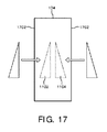
図17は、一つ又はそれより多くのフラックス低減要素1102及び1104が設置され、テーブルトップ134の側1702からテーブルトップ134から取り外される実施例を図示する。 図18は、一つ又はそれより多くのフラックス低減要素1102及び1104が設置され、テーブルトップ134の後ろ1802からテーブルトップ134から取り外される実施例を図示する。 他の例において、一つ又はそれより多くのフラックス低減要素1102及び1104は、テーブルトップ134に設置されることができて、テーブルトップ134の正面1804及び/又は他の領域からテーブルトップ134から取り外されることができる。 一つ又はそれより多くのフラックス低減要素1102及び1104は、アクセスを通じて設置されて、取り外される。
FIG. 17 illustrates an embodiment in which one or more
図19は、フラックスフィルタ装置130が複数のプレート1902を含むバリエーションを示す。 複数のプレート1902は、z方向のビームのサイズより大きい、z方向に渡って不変断面を有する。スキャンの間、複数のプレート1902は、複数のプレート1902の位置が回転ガントリ102に関して変わらないように、テーブルトップ134内において動かされることができる。図 17及び18及び/又は他に関連して記述されるように、複数のプレート1902は、設置されることができ、テーブルトップ134から取り外されることができる。
FIG. 19 shows a variation in which the
図20は、一つ又はそれより多くの中空容器2002がテーブルトップ134の内側に配置されるバリエーションを示す。 このバリエーションにおいて、一つ又はそれより多くの中空容器2002は、導管2006を通じて高度吸収ガス2004(例えば、キセノン)を充填されることができる。 一つ又はそれより多くの中空容器2002の吸収は、圧力レギュレータ2008を介して一つ又はそれより多くの中空容器2002の内側のガスの圧力を調節することによって修正されることができる。ガス2004及び/又は中空容器2002は、被験体支持部128のベース132、静止ガントリ104、照射されないテーブルトップ134の部分、及び/又はその他にもたらされる。
FIG. 20 shows a variation in which one or more
図20のバリエーションにおいて、一つ又はそれより多くの中空容器2002は、バッグ、風船等のような膨張可能及び/又は柔軟な容器を含む。 膨張可能及び/又は柔軟な容器は、テーブルトップ134の内側及び/又は外側で使われることができる。 たとえば、膨張可能及び/又は柔軟な容器は、高度吸収ガス2004及び/又は他の吸収ガスで充填(又は予め充填)され、それからテーブルトップ134の外側の四肢の間に位置される。 この例において、膨張可能及び/又は柔軟な容器は、過度のフラックスが検出器アレイ112に達することを防ぐため、図 2-6及び16に示されるエアギャップ206及び1604を横切る放射線を減衰させる。膨張可能及び/又は柔軟な容器はしぼられ、四肢、支持又は保持装置及び/又はその他を介して所定の位置において保持される。
In the variation of FIG. 20, one or more
図11-20の構成の場合、ここに記述されるように、X線がまず患者1506及び1608を、それからフラックスフィルタ装置130の更なる減衰物質を横切るように、更なる減衰物質が患者1506及び1608と検出器アレイ112との間にあるときフラックスを減少させるように、並びにX線がまず更なる減衰物質を、それから患者1506及び1608を横切るように、更なる減衰物質が患者1506及び1608と検出器アレイ112との間にないときフラックスを増やすように管電流は変調されることができる。ここに記述されるように、これはドーズ非効率性を軽減することを容易にする。
In the configuration of FIGS. 11-20, as described herein, additional attenuation material is applied to the
図21は、ここに記述される実施例による他の方法を例示する。 FIG. 21 illustrates another method according to embodiments described herein.
以下の行為の順序は例示を意図するものであり限定的ではないことを理解すべきである。そのため、他の順序も本明細書で予期される。加えて、一つ若しくは複数の行為が省略され且つ/又は一つ若しくは複数の追加の行為が含められても良い。 It should be understood that the following sequence of actions is intended to be illustrative and not limiting. As such, other orders are also contemplated herein. In addition, one or more actions may be omitted and / or one or more additional actions may be included.
2102において、患者は被験体支持部128に位置決めされる。
At 2102, the patient is positioned on the
2104において、スキャンプロトコルは、コンソール126で選ばれる。 この例において、選択スキャンプロトコルは放射線源コントローラ110に、放射線源108角に依存して、少なくとも一つのより低い及びより高い異なるフラックスの間で放射線放出を変調する変調パターンで放射線放出を変調させる。
At 2104, a scan protocol is selected at
2106において、フラックスフィルタ装置130は、スキャンプロトコルパラメータに基づいてフラックスフィルタ装置130のセットから選ばれる。
At 2106, the
2108において、選択フラックスフィルタ装置130は、テーブルトップ134の位置に移動される。 ここに記述されるように、これは物理的機械装置1102及び1104を位置に動かすステップ、及び/又は高度吸収ガス2004で一つ又はそれより多くの中空容器2002を充填するステップを含む。
At 2108, the selected
2110において、患者は、変調パターンを使って、必要ならば、フラックスフィルタ装置130を動かしてスキャンされる。
At 2110, the patient is scanned using the modulation pattern, moving the
2112において、投影データは、ボリュメトリック画像データを生成するように再構成される。 At 2112, the projection data is reconstructed to generate volumetric image data.
通常、ここに記述されるフラックスフィルタ装置130の異なる実施例は、カウントレート問題を解決するためにフォトンカウンティング検出器を備えるX線及びCTシステムで使われることができる。フラックスフィルタ装置130の異なる実施例は、歯科学及び/又は非破壊検査等のような非医学用途に加えて、胸部、四肢などをスキャンする医学用途のために使われることができる。
Typically, different embodiments of the
本発明が好ましい実施形態に関して説明されてきた。上記の詳細な説明を読んで理解するとき、他者は修正形態及び改変形態に気付くことがある。添付の特許請求の範囲又はその均等物の範囲内に含まれる限り、本発明はそのような全ての修正形態及び改変形態を含むものとして構成されることを意図する。 The invention has been described with reference to the preferred embodiments. When reading and understanding the above detailed description, others may notice modifications and variations. The present invention is intended to be construed as including all such modifications and variations as fall within the scope of the appended claims or their equivalents.
Claims (16)
前記検査領域を横切る放射線を検出し、前記検出される放射線を示す信号を出力するように構成される放射線感受性ピクセルのアレイであって、前記放射線感受性ピクセルのアレイは、前記検査領域の間に、前記放射線源に対向して配置される、放射線感受性ピクセルのアレイと、
前記放射線源及び前記ピクセルの放射線感受性検出器アレイの間の前記検査領域に配置されるリジッドフラックスフィルタ装置であって、前記フラックスフィルタ装置は、前記検査領域を横切る前記放射線及びそれに関する入射をフィルタリングするように構成され、前記フラックスフィルタ装置を離れる前記放射線が所定のフラックスを有する、リジッドフラックスフィルタ装置と
を有する、イメージングシステム。 A radiation source configured to rotate around an examination area and emit radiation across the examination area;
An array of radiation sensitive pixels configured to detect radiation across the examination region and output a signal indicative of the detected radiation, the array of radiation sensitive pixels between the examination region, An array of radiation-sensitive pixels disposed opposite the radiation source;
A rigid flux filter device disposed in the examination region between the radiation source and the radiation sensitive detector array of the pixel, wherein the flux filter device filters the radiation across the examination region and incidents associated therewith. And a rigid flux filter device, wherein the radiation leaving the flux filter device has a predetermined flux.
を更に有する、請求項1乃至7の何れか一項に記載のイメージングシステム。 8. A source controller configured to modulate a radiation source current of the radiation source between at least one first flux and at least one second different flux. The imaging system described in 1.
を更に有する、請求項1乃至7の何れか一項に記載のイメージングシステム。 8. An imaging system according to any preceding claim, further comprising a source controller configured to maintain the same flux throughout the scan.
を更に有する、請求項1乃至10の何れか一項に記載のイメージングシステム。 A subject support comprising a tabletop having a major axis along the z-direction, further comprising a subject support, wherein the rigid flux filter device is disposed inside the tabletop. The imaging system according to any one of 10.
前記検査領域に配置されるリジッドフラックスフィルタ装置で前記検査領域を横切る前記放射線をフィルタリングするステップと、
前記放射線源に対向して位置される検出器ピクセルを用いて、前記検査領域の向かいで、前記フラックスフィルタ装置を横切る放射線を検出し、それを示す信号を生成するステップと
を有する、方法。 Rotating a radiation source around an examination area, the radiation source emitting radiation across the examination area;
Filtering the radiation across the examination area with a rigid flux filter device disposed in the examination area;
Detecting radiation across the flux filter device opposite the examination region using a detector pixel located opposite the radiation source and generating a signal indicative thereof.
Applications Claiming Priority (3)
| Application Number | Priority Date | Filing Date | Title |
|---|---|---|---|
| US201462082184P | 2014-11-20 | 2014-11-20 | |
| US62/082,184 | 2014-11-20 | ||
| PCT/IB2015/058691 WO2016079638A1 (en) | 2014-11-20 | 2015-11-11 | An x-ray flux reducer for a photon counting detector |
Publications (4)
| Publication Number | Publication Date |
|---|---|
| JP2017538470A true JP2017538470A (en) | 2017-12-28 |
| JP2017538470A5 JP2017538470A5 (en) | 2018-12-13 |
| JP7065611B2 JP7065611B2 (en) | 2022-05-12 |
| JP7065611B6 JP7065611B6 (en) | 2022-06-06 |
Family
ID=54695804
Family Applications (1)
| Application Number | Title | Priority Date | Filing Date |
|---|---|---|---|
| JP2017525971A Active JP7065611B6 (en) | 2014-11-20 | 2015-11-11 | X-ray flux reducer for photon counting detector |
Country Status (6)
| Country | Link |
|---|---|
| US (1) | US10959688B2 (en) |
| EP (1) | EP3220827B1 (en) |
| JP (1) | JP7065611B6 (en) |
| CN (1) | CN107072620B (en) |
| RU (1) | RU2699280C2 (en) |
| WO (1) | WO2016079638A1 (en) |
Families Citing this family (4)
| Publication number | Priority date | Publication date | Assignee | Title |
|---|---|---|---|---|
| JP2021504037A (en) * | 2017-11-28 | 2021-02-15 | コーニンクレッカ フィリップス エヌ ヴェKoninklijke Philips N.V. | Spectral imaging using a rotational spectrum filter |
| US10555708B2 (en) | 2018-06-07 | 2020-02-11 | Norad Designs LLC | Head and neck radiation shield structure |
| AU2019343950A1 (en) * | 2018-09-20 | 2021-04-22 | Egg Medical, Inc. | A sled-table for radiographic imaging and medical device integration |
| US11644587B2 (en) | 2021-01-20 | 2023-05-09 | Canon Medical Systems Corporation | Pixel summing scheme and methods for material decomposition calibration in a full size photon counting computed tomography system |
Family Cites Families (29)
| Publication number | Priority date | Publication date | Assignee | Title |
|---|---|---|---|---|
| US3715587A (en) | 1970-10-26 | 1973-02-06 | Norland Corp | Limb holder positioner for bone mineral analyzer |
| JPS52100991A (en) | 1976-02-20 | 1977-08-24 | Hitachi Medical Corp | Xxray sectional checker |
| NL8304398A (en) | 1983-12-22 | 1985-07-16 | Philips Nv | ROENTGEN RESEARCH DEVICE WITH SELECTIVE FILTER. |
| FR2561516B1 (en) * | 1984-03-20 | 1988-03-04 | Thomson Cgr | COMPENSATOR FILTER RADIOLOGY SYSTEM |
| JPS61106204A (en) * | 1984-10-31 | 1986-05-24 | Fuji Eng:Kk | Forming of embossed plywood |
| JPS61106204U (en) * | 1984-10-31 | 1986-07-05 | ||
| JPH09329699A (en) | 1996-06-06 | 1997-12-22 | Sumitomo Rubber Ind Ltd | Compensating filter for x-ray photography |
| IL120097A0 (en) | 1997-01-29 | 1997-04-15 | Elscint Ltd | Variable current CT scanning |
| US6836535B2 (en) * | 2002-04-22 | 2004-12-28 | General Electric Company | Method and apparatus of modulating the filtering of radiation during radiographic imaging |
| US6744846B2 (en) | 2002-09-26 | 2004-06-01 | Siemens Aktiengesellschaft | Method and apparatus for automatic exposure control in CT scanning |
| WO2004071301A1 (en) * | 2003-02-14 | 2004-08-26 | Hitachi Medical Corporation | X-ray ct device |
| JP4509493B2 (en) | 2003-04-25 | 2010-07-21 | ジーイー・メディカル・システムズ・グローバル・テクノロジー・カンパニー・エルエルシー | X-ray CT image capturing method and X-ray CT apparatus |
| EP1646316B1 (en) * | 2003-07-15 | 2009-12-16 | Koninklijke Philips Electronics N.V. | Computed tomography scanner with large gantry bore |
| US7313217B2 (en) * | 2003-10-27 | 2007-12-25 | General Electric Company | System and method of collecting imaging subject positioning information for x-ray flux control |
| US7303334B2 (en) * | 2004-03-25 | 2007-12-04 | Worldwide Innovations & Technologies, Inc. | Radiation attenuation system |
| US7558364B2 (en) | 2004-04-13 | 2009-07-07 | Koninklijke Philips Electronics N.V. | Dynamic dose control for computed tomography |
| JP2006158690A (en) | 2004-12-08 | 2006-06-22 | Ge Medical Systems Global Technology Co Llc | Radiation ct apparatus and method for controlling radiation of radiation ct apparatus |
| DE102005014853A1 (en) * | 2005-03-30 | 2006-10-12 | Siemens Ag | A tomographic device for fast volume scanning of an examination area and method for fast volume scanning of the examination area with such a tomography device |
| DE102005026940A1 (en) * | 2005-06-06 | 2006-12-14 | Schering Ag | X-ray arrangement for image presentation of an examination subject and use of the X-ray arrangement |
| CN201088591Y (en) | 2007-10-15 | 2008-07-23 | 尚汝斌 | Radiation protection device for CT examination |
| JP5523726B2 (en) | 2008-04-04 | 2014-06-18 | 株式会社東芝 | X-ray CT system |
| BRPI0910206A2 (en) * | 2008-06-30 | 2015-09-29 | Koninkl Philips Electronics Nv | computed tomography imaging system and method |
| CN102271587B (en) * | 2009-01-12 | 2013-12-04 | 皇家飞利浦电子股份有限公司 | Method and apparatus to filter x-ray beams generated using a CT apparatus with displaced geometry |
| RU2589723C2 (en) * | 2010-09-30 | 2016-07-10 | Конинклейке Филипс Электроникс Н.В. | Dynamic filter for computed tomography (ct) |
| WO2012077027A1 (en) * | 2010-12-09 | 2012-06-14 | Koninklijke Philips Electronics N.V. | Post-patient dynamic filter for computed tomography (ct) |
| WO2013132361A2 (en) | 2012-03-07 | 2013-09-12 | Koninklijke Philips N.V. | X-ray beam shaper. |
| JP2013236685A (en) | 2012-05-11 | 2013-11-28 | Toshiba Corp | X-ray ct apparatus |
| DE102012217301B4 (en) * | 2012-09-25 | 2021-10-14 | Bayer Pharma Aktiengesellschaft | Combination of contrast agent and mammography CT system with a specified energy range and method for generating tomographic mammography CT images using this combination |
| JP5784090B2 (en) | 2013-09-30 | 2015-09-24 | 株式会社東芝 | X-ray CT system |
-
2015
- 2015-11-11 WO PCT/IB2015/058691 patent/WO2016079638A1/en active Application Filing
- 2015-11-11 JP JP2017525971A patent/JP7065611B6/en active Active
- 2015-11-11 US US15/525,079 patent/US10959688B2/en active Active
- 2015-11-11 RU RU2017121289A patent/RU2699280C2/en active
- 2015-11-11 CN CN201580062900.1A patent/CN107072620B/en active Active
- 2015-11-11 EP EP15798245.5A patent/EP3220827B1/en active Active
Also Published As
| Publication number | Publication date |
|---|---|
| RU2017121289A (en) | 2018-12-20 |
| RU2017121289A3 (en) | 2019-03-27 |
| JP7065611B6 (en) | 2022-06-06 |
| CN107072620B (en) | 2023-04-25 |
| EP3220827A1 (en) | 2017-09-27 |
| CN107072620A (en) | 2017-08-18 |
| RU2699280C2 (en) | 2019-09-04 |
| WO2016079638A1 (en) | 2016-05-26 |
| US10959688B2 (en) | 2021-03-30 |
| JP7065611B2 (en) | 2022-05-12 |
| US20170332984A1 (en) | 2017-11-23 |
| EP3220827B1 (en) | 2020-01-15 |
Similar Documents
| Publication | Publication Date | Title |
|---|---|---|
| EP2822467B1 (en) | X-ray beam shaper | |
| JP5920912B2 (en) | System for dynamic region of interest collimation imaging using x-ray computed tomography and method of operation thereof | |
| JP7065611B2 (en) | X-ray flux reducer for photon counting detector | |
| CN107530036B (en) | Apparatus, system and method for radiological imaging | |
| US9265471B2 (en) | Determination of a multi-energy image | |
| US7639773B2 (en) | X-ray CT apparatus and method of generating an image | |
| US20030058994A1 (en) | Computed tomography method and apparatus for registering data with reduced radiation stress to the patient | |
| JP2016198505A (en) | Scatter correction apparatus and scatter correction method | |
| US20170296132A1 (en) | Method for estimation and correction of grid pattern due to scatter | |
| JP2022545086A (en) | Detection of geometric calibration markers in spectral tomosynthesis systems | |
| US20160073998A1 (en) | X-ray diagnostic apparatus | |
| JP6778337B2 (en) | Dose modulation of photon scanning device | |
| KR101501101B1 (en) | Radiation imaging apparatus, computed tomography and method for obtaining radiation image | |
| JP7161422B2 (en) | Tomosynthesis Imaging Apparatus, Tomosynthesis Imaging Apparatus Operating Method, Tomosynthesis Imaging Apparatus Operating Program | |
| WO2024042901A1 (en) | X-ray imaging device | |
| WO2023175244A1 (en) | Tomographic radiography and calibration | |
| Ning et al. | Flat panel detector-based cone beam CT for dynamic imaging: system evaluation |
Legal Events
| Date | Code | Title | Description |
|---|---|---|---|
| A521 | Request for written amendment filed |
Free format text: JAPANESE INTERMEDIATE CODE: A523 Effective date: 20181101 |
|
| A621 | Written request for application examination |
Free format text: JAPANESE INTERMEDIATE CODE: A621 Effective date: 20181101 |
|
| A977 | Report on retrieval |
Free format text: JAPANESE INTERMEDIATE CODE: A971007 Effective date: 20190927 |
|
| A131 | Notification of reasons for refusal |
Free format text: JAPANESE INTERMEDIATE CODE: A131 Effective date: 20191010 |
|
| A601 | Written request for extension of time |
Free format text: JAPANESE INTERMEDIATE CODE: A601 Effective date: 20200107 |
|
| A521 | Request for written amendment filed |
Free format text: JAPANESE INTERMEDIATE CODE: A523 Effective date: 20200410 |
|
| A02 | Decision of refusal |
Free format text: JAPANESE INTERMEDIATE CODE: A02 Effective date: 20200728 |
|
| A521 | Request for written amendment filed |
Free format text: JAPANESE INTERMEDIATE CODE: A523 Effective date: 20201130 |
|
| C60 | Trial request (containing other claim documents, opposition documents) |
Free format text: JAPANESE INTERMEDIATE CODE: C60 Effective date: 20201130 |
|
| A911 | Transfer to examiner for re-examination before appeal (zenchi) |
Free format text: JAPANESE INTERMEDIATE CODE: A911 Effective date: 20201208 |
|
| C21 | Notice of transfer of a case for reconsideration by examiners before appeal proceedings |
Free format text: JAPANESE INTERMEDIATE CODE: C21 Effective date: 20201210 |
|
| A912 | Re-examination (zenchi) completed and case transferred to appeal board |
Free format text: JAPANESE INTERMEDIATE CODE: A912 Effective date: 20210122 |
|
| C211 | Notice of termination of reconsideration by examiners before appeal proceedings |
Free format text: JAPANESE INTERMEDIATE CODE: C211 Effective date: 20210126 |
|
| C22 | Notice of designation (change) of administrative judge |
Free format text: JAPANESE INTERMEDIATE CODE: C22 Effective date: 20210218 |
|
| C13 | Notice of reasons for refusal |
Free format text: JAPANESE INTERMEDIATE CODE: C13 Effective date: 20210622 |
|
| A601 | Written request for extension of time |
Free format text: JAPANESE INTERMEDIATE CODE: A601 Effective date: 20210910 |
|
| A521 | Request for written amendment filed |
Free format text: JAPANESE INTERMEDIATE CODE: A523 Effective date: 20211221 |
|
| C23 | Notice of termination of proceedings |
Free format text: JAPANESE INTERMEDIATE CODE: C23 Effective date: 20220324 |
|
| C03 | Trial/appeal decision taken |
Free format text: JAPANESE INTERMEDIATE CODE: C03 Effective date: 20220421 |
|
| C30A | Notification sent |
Free format text: JAPANESE INTERMEDIATE CODE: C3012 Effective date: 20220421 |
|
| A61 | First payment of annual fees (during grant procedure) |
Free format text: JAPANESE INTERMEDIATE CODE: A61 Effective date: 20220426 |
|
| R150 | Certificate of patent or registration of utility model |
Ref document number: 7065611 Country of ref document: JP Free format text: JAPANESE INTERMEDIATE CODE: R150 |