JP2017536304A - Articles printed and decorated digitally - Google Patents
Articles printed and decorated digitally Download PDFInfo
- Publication number
- JP2017536304A JP2017536304A JP2017525628A JP2017525628A JP2017536304A JP 2017536304 A JP2017536304 A JP 2017536304A JP 2017525628 A JP2017525628 A JP 2017525628A JP 2017525628 A JP2017525628 A JP 2017525628A JP 2017536304 A JP2017536304 A JP 2017536304A
- Authority
- JP
- Japan
- Prior art keywords
- article
- deposition device
- deposited
- predetermined pattern
- pass
- Prior art date
- Legal status (The legal status is an assumption and is not a legal conclusion. Google has not performed a legal analysis and makes no representation as to the accuracy of the status listed.)
- Pending
Links
Images


Classifications
-
- B—PERFORMING OPERATIONS; TRANSPORTING
- B41—PRINTING; LINING MACHINES; TYPEWRITERS; STAMPS
- B41J—TYPEWRITERS; SELECTIVE PRINTING MECHANISMS, i.e. MECHANISMS PRINTING OTHERWISE THAN FROM A FORME; CORRECTION OF TYPOGRAPHICAL ERRORS
- B41J3/00—Typewriters or selective printing or marking mechanisms characterised by the purpose for which they are constructed
- B41J3/407—Typewriters or selective printing or marking mechanisms characterised by the purpose for which they are constructed for marking on special material
- B41J3/4073—Printing on three-dimensional objects not being in sheet or web form, e.g. spherical or cubic objects
-
- B—PERFORMING OPERATIONS; TRANSPORTING
- B41—PRINTING; LINING MACHINES; TYPEWRITERS; STAMPS
- B41M—PRINTING, DUPLICATING, MARKING, OR COPYING PROCESSES; COLOUR PRINTING
- B41M5/00—Duplicating or marking methods; Sheet materials for use therein
- B41M5/0082—Digital printing on bodies of particular shapes
- B41M5/0088—Digital printing on bodies of particular shapes by ink-jet printing
-
- B—PERFORMING OPERATIONS; TRANSPORTING
- B44—DECORATIVE ARTS
- B44F—SPECIAL DESIGNS OR PICTURES
- B44F9/00—Designs imitating natural patterns
- B44F9/10—Designs imitating natural patterns of metallic or oxidised metallic surfaces
-
- B—PERFORMING OPERATIONS; TRANSPORTING
- B41—PRINTING; LINING MACHINES; TYPEWRITERS; STAMPS
- B41M—PRINTING, DUPLICATING, MARKING, OR COPYING PROCESSES; COLOUR PRINTING
- B41M5/00—Duplicating or marking methods; Sheet materials for use therein
- B41M5/0082—Digital printing on bodies of particular shapes
- B41M5/0094—Digital printing on bodies of particular shapes by thermal printing
Abstract
三次元の物品に直接印刷する、及び/又は三次元の物品を装飾する装置及び方法を含む、物品の表面上に物質を堆積させるための装置及び方法、並びに(印刷など)その上に物質を有する、及び/又はそれで装飾される物品が開示される。場合によっては、装置及び方法は、装飾デバイスによって物品に装飾効果を提供すること、及び少なくとも1つの物品と物質堆積デバイスとの間に再循環する相対運動を生じさせることを伴う。いくつかの実施形態では、物品は、1つ又は2つ以上の物質堆積デバイスを通り過ぎて閉ループ経路に搬送され得る。物品は、1回又は2回以上物質堆積デバイス(複数可)を通り過ぎて搬送され得、物質堆積デバイス(複数可)による各パスの間に、所定のパターンの一部が、物質堆積デバイス(複数可)によって物品に適用され得る。Apparatus and method for depositing a substance on the surface of the article, including apparatus and method for printing directly on and / or decorating a three-dimensional article, and a substance thereon (such as printing) Articles having and / or decorated therewith are disclosed. In some cases, the apparatus and method involve providing a decorative effect to the article by the decorative device and creating a recirculating relative motion between the at least one article and the material deposition device. In some embodiments, the article may be transported through a closed loop path past one or more material deposition devices. The article may be conveyed past the material deposition device (s) one or more times, and during each pass through the material deposition device (s), a portion of the predetermined pattern may be transferred to the material deposition device (s). Yes) can be applied to the article.
Description
本発明は、三次元の物品に直接印刷する、及び/又は三次元の物品を装飾する装置及び方法を含む、物品の上に物質を堆積させるための装置及び方法、並びに(印刷など)その上に物質を有する、及び/又はそれで装飾される物品を対象とする。 The present invention relates to an apparatus and method for depositing material on an article, including an apparatus and method for directly printing on and / or decorating a three-dimensional article, and (such as printing) thereon Articles having and / or decorated with a substance.
印刷の様々な装置及び方法が、特許文献において、及びインターネット上で開示されている。印刷の装置及び方法を開示する特許公報としては、米国特許第6,135,654号(Jennel)、同第6,699,352(B2)号(Sawatsky)、同第7,210,408(B2)号(Uptergrove)、同第7,467,847(B2)号(Baxterら)、同第8,522,989(B2)号(Uptergrove)、同第8,579,402(B2)号(Uptergrove)、同第8,667,895(B2)号(Gerigkら)、及び米国特許出願公開第2011/0232514(A1)号(Putzerら)、同第2013/0019566(A1)号(Schach)、同第2014/0285600(A1)号(Domeierら)、及び国際公開第2015/036334号(Till)が挙げられる。さらに、Xennia Technologyは、You Tubeに、割出し動作する方式で移動する印刷機構を使用して、移動する幟材への印刷プロセスを示す「Digital Outdoor Textile Printing」と題されたビデオを投稿した。その他のタイプの装置及び方法としては、Broadの名前で出願された米国特許出願公開第2012/0031548(A1)号、「Apparatus and Method for Applying a Label to a Non−Ruled Surface」に開示される装置及び方法が挙げられる。 Various printing devices and methods are disclosed in the patent literature and on the Internet. Patent publications disclosing printing apparatuses and methods include US Pat. Nos. 6,135,654 (Jennel), 6,699,352 (B2) (Sawatsky), and 7,210,408 (B2). No.) (Uppergrove), No. 7,467,847 (B2) (Baxter et al.), No. 8,522,989 (B2) (Uptergrove), No. 8,579,402 (B2) (Uptergrove) No. 8,667,895 (B2) (Gerigg et al.), And US Patent Application Publication No. 2011/0232514 (A1) (Putzer et al.), No. 2013/0019566 (A1) (Schach), 2014/0285600 (A1) (Domeier et al.) And International Publication No. 2015/036334 (Till) And the like. In addition, Xenia Technology has posted a video entitled “Digital Output Textile Printing” to You Tube that shows the printing process on the moving wood using a printing mechanism that moves in an indexing manner. Other types of devices and methods include those disclosed in U.S. Patent Application Publication No. 2012/0031548 (A1), "Appratus and Methods for Applying a Label to a Non-Ruled Surface," filed under the name of "Broad". And methods.
多くの現在の取り組みは、ボトルなどの三次元の物品への印刷、特にインクジェット印刷を目的としている。現在の印刷装置は、シングルパスタイプ又はマルチパスタイプのどちらかであり得る。シングルパス装置は、マルチパス装置より速いという利点を有する。マルチパス装置は、より良好な品質を実現することができるが、割出し動作する方式ではプリントヘッドが物品を複数回通過する必要があるので、シングルパス装置よりも遅い。残念ながら、現在のインクジェット技術及び現在の印刷装置を用いて、三次元の物品に直接印刷することによって形成され得るラベルの品質は、別個に印刷された平坦なラベル上に形成されたものほど良好ではない。取り組みのほとんどは、シングルパス装置の品質を改善しようとすることを目的とするように見える。印刷、特に三次元の物品への印刷に関する改善された装置及び方法の必要性が存在する。 Many current efforts are aimed at printing on three-dimensional articles such as bottles, especially inkjet printing. Current printing devices can be either single-pass type or multi-pass type. Single path devices have the advantage of being faster than multipath devices. Multi-pass devices can achieve better quality, but are slower than single-pass devices because the indexing scheme requires the printhead to pass through the article multiple times. Unfortunately, the quality of labels that can be formed by printing directly on a three-dimensional article using current inkjet technology and current printing equipment is better for those formed on separately printed flat labels. is not. Most of the efforts appear to be aimed at improving the quality of single pass devices. There is a need for improved apparatus and methods for printing, particularly for printing on three-dimensional articles.
本発明は、三次元の物品に直接印刷する、及び/又は三次元の物品を装飾する装置及び方法を含む、物品の表面上に物質を堆積させるための装置及び方法、並びに(印刷など)その上に物質を有する、及び/又はそれで装飾される物品を対象とする。 The present invention relates to an apparatus and method for depositing a substance on the surface of an article, including an apparatus and method for printing directly on and / or decorating a three-dimensional article, and (such as printing) Intended for articles having and / or decorated with a substance thereon.
場合によっては、装置及び方法は、少なくとも1つの物品と物質堆積デバイス及び/又は機能デバイスとの間に再循環する相対運動を生じさせることを伴う。いくつかの実施形態では、物品は、1つ若しくは2つ以上の物質堆積デバイス及び/又は機能デバイスを通り過ぎて閉ループ経路に搬送され得る。物品は、1回又は2回以上物質堆積デバイス(複数可)を通り過ぎて搬送され得、物質堆積デバイス(複数可)による各パスの間に、所定のパターンの一部が、物質堆積デバイス(複数可)によって物品に適用され得る。 In some cases, the apparatus and method involve creating a recirculating relative motion between at least one article and the material deposition device and / or functional device. In some embodiments, the article may be conveyed through a closed loop path past one or more material deposition devices and / or functional devices. The article may be conveyed past the material deposition device (s) one or more times, and during each pass through the material deposition device (s), a portion of the predetermined pattern may be transferred to the material deposition device (s). Yes) can be applied to the article.
装置は、物品で機能を実行するための1つ又は2つ以上の追加のステーションにおいて1つ又は2つ以上の機能デバイスを備えてもよい。機能デバイスとしては、追加の物質堆積デバイス、物品を処理するためのデバイス(例えば、物品の表面を処理する、又は物品に適用される物質を硬化させるためのデバイス)、物品を装飾するためのデバイス(例えば、金属箔の適用)、物品の特性を変えるためのデバイス(例えば、レーザー)、又はこれらの組み合わせを挙げることができるが、これらに限定されない。 The apparatus may comprise one or more functional devices at one or more additional stations for performing functions on the article. Functional devices include additional material deposition devices, devices for treating articles (eg, devices for treating the surface of articles or curing substances applied to articles), devices for decorating articles (For example, application of a metal foil), a device for changing the properties of an article (eg, a laser), or a combination thereof may be mentioned, but is not limited thereto.
図面に示される方法、装置(複数可)、及び物品の実施形態は、実際には例証であり、特許請求の範囲によって定義された本発明を制限することを意図しない。さらに、本発明の各特徴は、「発明を実施するための形態」に照らし合わせれば、より完全に明確になり理解されるであろう。 The method, apparatus (s), and article embodiments shown in the drawings are illustrative in nature and are not intended to limit the invention as defined by the claims. Furthermore, each feature of the present invention will become more fully apparent and understood in light of the Detailed Description.
本発明は、三次元の物品に直接印刷する、及び/又は三次元の物品を装飾する装置及び方法を含む、物品の表面上に物質を堆積させるための装置及び方法、並びに(印刷など)その上に物質を有する、及び/又はそれで装飾される物品を対象とする。「方法」という用語は、本明細書において「プロセス」という用語と互換的に使用され得る。 The present invention relates to an apparatus and method for depositing a substance on the surface of an article, including an apparatus and method for printing directly on and / or decorating a three-dimensional article, and (such as printing) Intended for articles having and / or decorated with a substance thereon. The term “method” may be used interchangeably herein with the term “process”.
図1及び2Aは、少なくとも1つの物品10に物質22を堆積させるための装置20の1つの非限定的な実施形態を示す。図1及び2Aに示すように、装置20は、物質堆積デバイス26が位置する少なくとも1つのステーション25Aを通り過ぎて少なくとも1つの物品10を搬送する物品コンベヤー24を備える。「コンベヤー」という用語は、本明細書で使用するとき、一般的に物品を移動させるデバイスを指し、コンベヤーベルトに限定されない。
1 and 2A show one non-limiting embodiment of an
装置20は、多数の異なるタイプの三次元の物品10に物質又は材料22を堆積させるために使用され得る。そのような物品としては、キャップ、栓、ボトル、箱、缶、カートン、容器、洗濯用投入ボール(laundry dosing ball)、かみそり、かみそり刃ヘッド及びハンドルなどの消費者製品の構成要素、噴霧器トリガ、たらい、限定するものではないがタンポンの筒などの筒、並びにデオドラントスティック容器が挙げられるが、これらに限定されない。物品には、使い捨て消費者製品を含む消費者製品の一次パッケージを挙げることができる。さらなる物品としては、ボトルキャップ、及び続いて完成したボトルの形状に吹き込まれるボトルのプリフォームが挙げられるがこれらに限定されない、容器又はパッケージの構成要素が挙げられる。装置20を使用して、空容器、部分的に充填された容器、又は充填された容器を搬送及び印刷することができる。容器は、全部又は一部に剛性又は可撓性の構造を有することができる。そのような容器は、キャップをしていても、キャップをしていなくてもよい。物品は、プラスチック、金属、及び/又はボール紙が挙げられるがこれらに限定されない、任意の好適な材料で作製され得る。
The
物質堆積デバイス(複数可)(「堆積デバイス」)26は、任意の好適な物質(即ち「材料」)を物品10に堆積させることができる。好適な材料としては、インク(UV硬化性インク、及びアクリレート系インクなど)、コーティング、及びローションが挙げられるが、これらに限定されない。材料は、いずれか好適な形態で堆積され得る。好適な形態としては、液体、粉末、及びホットメルト(後者は加熱して流れ得る固体である)が挙げられるが、これらに限定されない。材料は、任意の好適なパターンで堆積され得る。好適なパターンは、規則的若しくは不規則であってもよく、デザイン、画像、テキスト、しるし、テクスチャ、機能被膜、及びそれらの組み合わせが挙げられるが、これらに限定されない。堆積デバイス26は、インクジェットプリントヘッド、ノズル、及びその他のタイプの材料堆積デバイスが挙げられるがこれらに限定されない、任意の好適なタイプのデバイスであり得る。
Material deposition device (s) (“deposition device”) 26 may deposit any suitable material (ie, “material”) on
装置20及び方法は、物品10と堆積デバイス(複数可)26との間に1つ又は2つ以上のタイプの相対運動を生じさせてよい。相対運動は、(1)堆積デバイス26に対して物品(複数可)10を移動させる、(2)物品(複数可)10に対して堆積デバイス26を移動させる、又は物品(複数可)10及び堆積デバイス26の両方を互いに対して移動させることによって生じ得る。物品(複数可)10と堆積デバイス(複数可)26との間に2つ以上の異なるタイプの相対運動が存在し得る。装置及び方法が物品と堆積デバイスとの間に2つ以上の異なるタイプの相対運動を生じさせる場合は、これらを、本明細書において第1のタイプの相対運動、第2のタイプの相対運動などと呼ぶ。
The
図1に矢印Fで示される第1のタイプの相対運動は、任意の好適な目的のために提供され得る。特定の非限定的な実施形態において、コンベヤー24が物品10と堆積デバイス26との間の移動の少なくとも部分的な非線形運動をもたらすとき、第1のタイプの相対運動が生じる。このタイプの相対運動は、物品10に2回以上堆積デバイス26を通過するサイクル(又は「パス」)を受けさせるためにもたらされ得る。堆積デバイス26は、そのような場合において、地面に対して静止若しくは固定され得るか、又は(後述のように)移動可能であり得る。堆積デバイス26が移動可能である場合、堆積デバイス26は、その運動を特定の方向及び特定の量に限定してよい。物品(複数可)10は、少なくとも2回堆積デバイス26を通過してよい。物品(複数可)10は、堆積デバイス26を、2、3、4、5回など最大20回又はそれ以上の回数が挙げられるがこれらに限定されない、任意の好適な回数通過することができる。
A first type of relative motion, indicated by arrow F in FIG. 1, may be provided for any suitable purpose. In certain non-limiting embodiments, a first type of relative motion occurs when the
いくつかの実施形態では、再循環ループの形態で物品コンベヤー24を設けることによって、少なくとも部分的な非線形運動を実現することができる。再循環ループは、任意の好適な構成であることができる。コンベヤー24は、円形路などの曲線経路で、又は線形部分及び曲線部分の両方を含む経路で移動する(したがって、物品10を移動させる)ことができる。そのような経路の非限定的な例としては、円形路、楕円形路、レーストラック型に構成された経路、及びその他の閉ループ経路が挙げられる。再循環ループは、少なくともその一部の間に、物品自体の軸と異なる(例えば、オフセットした)軸の周りでの物品(複数可)10の移動を含む。したがって、物品をそれ自体の軸の周りで急回転させること(缶をマンドレル上の缶自体の軸の周りで急回転させるなど)は、「再循環ループ」であると見なされない。
In some embodiments, at least partial non-linear motion can be achieved by providing the
図1は、少なくとも1つの物品10への印刷など物質22を堆積させるための装置20の1つの非限定的な実施形態を示す。物品10は、堆積デバイス26に対して弓状の経路に沿って移動する。より具体的には、図1に示されるコンベヤー24は、「タレット」型回転デバイスにおいて円形路Pで物品10を移動させる。図1に示すように、コンベヤー24は、回転軸Aを有する。回転軸Aは、垂直方向(コンベヤーがカルーセルのように回転するように)、水平方向(コンベヤーが観覧車のように回転するように)、又は水平と垂直との間のいくつかの方向など、任意の好適な方向に配向されてもよい。
FIG. 1 shows one non-limiting embodiment of an
再循環ループは、物品(複数可)を直動キャリッジ型デバイスより高速(単位時間あたりの物品)で複数回堆積デバイスに提示できるようにして、物品(複数可)10への材料のマルチパス堆積を可能にする。例えば、2回のパスを使用して三次元の物品に物質を堆積させるフラットベッドキャリッジ型デバイスの一種は、1分あたり12個の物品の速度で印刷する。物品(複数可)の寸法に応じて、本発明の方法は、最大60個又はそれ以上の物品/分の印刷が可能であり得る。 The recirculation loop allows multi-pass deposition of material onto the article (s) 10 so that the article (s) can be presented to the deposition device multiple times faster (articles per unit time) than the linear carriage type device. Enable. For example, one type of flatbed carriage type device that uses two passes to deposit material on a three-dimensional article prints at a rate of 12 articles per minute. Depending on the size of the article (s), the method of the invention may be capable of printing up to 60 or more articles / minute.
コンベヤー24は、堆積デバイス26を通過して物品(複数可)10を搬送するための任意の好適なタイプのデバイスであり得る。好適なコンベヤーとしては、タレットコンベヤー、スターホイールコンベヤー、トラック、ベルト、チェーンなどの形態であってもよい無限ループコンベヤーが挙げられるが、これらに限定されない。図1、2A、及び2Bに示すように、コンベヤー24は、キャリア28、及びキャリア28に接合されている少なくとも1つのオプションの物品10用ホルダー30を備えてもよい。「接合した」という用語は、ある要素を他の要素に直接固着することによってある要素を別の要素に直接固定する構成、ある要素を中間部材(類)に固着し次にその中間部材を他の要素に固着することによってある要素を他の要素に間接的に固定する構成、及び、ある要素が別の要素と一体化する構成、即ちある要素が他の要素の本質的な一部分である構成、を包含する。2つ以上のホルダー30が存在する場合、ホルダーは、任意の好適な構成でキャリア28に接合され得る。好適な構成としては、円形キャリア28を取り巻く放射状配列が挙げられるが、これに限定されない。
The
図1及び2Aに示すように、キャリア28は、水平面H内で、この場合は垂直である軸Aの周りを大きな矢印Fの方向に回転し得る。図1では、回転方向Fは、時計回りである。他の実施形態において、回転方向は、時計と反対方向であってもよい。典型的には、コンベヤー24は、堆積デバイス(複数可)26を通り過ぎる物品(複数可)のパス間で、同じ方向(場合に応じて、時計回り又は時計と反対方向)に回転するであろう。したがって、コンベヤー24は、通常はしないが、堆積デバイス(複数可)26を通り過ぎる物品の1回のパスの間に時計回りに回転し、次に別のパスの間に時計と反対方向に回転してもよい(逆もまた同様)。コンベヤー24は、等速で回転してもよいか、又は必要に応じて回転速度を変えることができる。コンベヤー24の回転は、連続的であっても又は必要に応じて断続的であってもよい。物品(複数可)10は、物品が搬送される経路Pに沿った任意の所与の場所における物品10の移動方向(及び速度)を表すベクトルVを有する。
As shown in FIGS. 1 and 2A, the
図1、2A、及び2Bに示すように、堆積デバイス26及びホルダー30は、キャリア28に対していくつかの可能な位置にあり得る。図1及び2Aに示す実施形態において、堆積デバイス(複数可)26が、物品10を保持するホルダー30を含むキャリア28の部分の上に配設されることが望ましい場合がある。図2Aでは、物品10は、水平面H内で移動する。物品10が堆積デバイス26の下にあるとき、物品10の移動方向Vは、描画図形の平面に延びる垂線である。そのような場合、物質22は、垂直軸Aに実質的に平行であり、物品が移動する(この場合は水平面Hである)平面に実質的に垂直である塗布方向Dを有する。塗布方向Dが、水平面Hに実質的に垂直であると言われるとき、塗布方向は、物品移動方向に対して正確に垂直であってもよいが、そうである必要はない。
As shown in FIGS. 1, 2A, and 2B, the
他の実施形態において、図2Bに示すように、またキャリア28も、水平面H内などの平面内で垂直軸Aの周りを回転する。この実施形態において、物品10も、堆積デバイス26に近接するとき、Vが描画図形の平面に延びる垂線である方向に水平面H内で移動する。しかしながら、この実施形態において、塗布方向Dは、水平面Hに対して平行又は実質的に平行であり、物品ホルダー30は、物品10が堆積デバイス26に対向するように、キャリア28の辺縁の側部に位置する。そのような場合において、物品10は、水平面H内で移動し、物質22は、水平面Hに対して(図2Aにおけるように実質的に垂直ではなく)平行である塗布方向Dを有する。しかしながら、この実施形態において、また塗布方向Dも、物品が物品に対して物質を塗布するための堆積デバイス26に近接した位置にあるとき、物品(複数可)の移動方向V(ただし三次元空間内の別の態様で)に対して垂直又は実質的に垂直である。
In other embodiments, as shown in FIG. 2B, the
他の実施形態において、堆積デバイス(複数可)26は、物品10の進行路Pの内側に位置し得る。さらに、図2A及び2Bに示す実施形態のいずれかでキャリア28が、垂直面内で(又は水平と垂直との間に配向された一部の平面内で)存在し回転するように傾斜している場合は、塗布方向Dは、それらの実施形態で記載された回転面と同じ関係のままであってもよいが、回転面は、場合に応じて垂直になるか、又は水平と垂直との間に配向される。
In other embodiments, the deposition device (s) 26 may be located inside the travel path P of the
図3は、少なくとも1つの物品10に物質22を堆積させるための装置20の代替的な実施形態を示す。図3に示す実施形態において、物品コンベヤー24は、レーストラック構成である。このタイプのコンベヤーは、進行路の少なくとも一部の間にコンベヤー24及び物品10が回転する2本の平行な軸を有する。これらの軸は、A1及びA2に指定されている。図3に示される装置20は、その方向(水平又は垂直)、及びコンベヤー24に対する堆積デバイス(複数可)26の配置、及びその上のあらゆる物品ホルダー30の配置が挙げられるがこれらに限定されない、図1、2A、及び2Bに示される装置に関して上述した特性のいずれかを有することができる。そのようなレーストラックの実施形態では、図3に示すように、堆積デバイス(複数可)26がレーストラック状の経路の末端部32の一方に位置するか、レーストラック状の経路の側部34の一方に沿って位置するかに応じて、物品(複数可)10が堆積デバイス(複数可)26を通り過ぎて曲線経路又は線形経路上のいずれかを移動するように、堆積デバイス(複数可)26を配置することが可能である。どちらの場合にも、物品10が移動する経路は、連続ループのままであり、物品(複数可)10が2回目(以降)に所与の堆積デバイス26を通り過ぎて移動するとき、物品は、1回目に堆積デバイス26を通り過ぎて移動したときと同じ方向に移動することになる。したがって、物品10は、通常はしないが、堆積デバイス26を通り過ぎる各パスで反対の方向に移動してもよい。例えば、物品10は、通常はしないが、1回のパスで時計回りに、別のパスで時計と反対方向に移動してもよい。
FIG. 3 shows an alternative embodiment of an
図3Aは、少なくとも1つの物品10に物質を堆積させるための装置20の別の代替的な実施形態を示す。図3Aに示す実施形態では、物品コンベヤー24は、実質的に円筒の形状であるが、その中に少なくとも1つの物品10のための収容部を提供する陥凹部を有する。コンベヤー24は、1、2〜20個以上の収容部を備え得る。示される実施形態には、4つの収容部があり、それぞれは、中に物品10を入れて示されている。収容部は、物品(複数可)10を保持するのに好適な任意の形状であり得る。図3Aに示されるように、コンベヤー24は、矢印Fの方向になど、軸Aの周りを回転する。コンベヤー24は、半径Rを有する。この実施形態は、その上に堆積される物質を有する物品10の表面12の部分が実質的に円筒形のコンベヤー24と同じ曲率、又は実質的に同じ曲率を有するとき、特に有用である。例えば、物品の表面12のその部分は、コンベヤー24の半径Rと実質的に同じ半径を有してもよい(したがって、物品10の表面12の外側に面する部分は、コンベヤー24に沿って円筒形の面を少なくとも部分的に形成(又は完全に形成)してもよい)。装置20はまた、物品上に堆積した物質の乾燥又は硬化のためのオプションのデバイス50も有してもよい。乾燥又は硬化デバイス50は、堆積デバイス26に対してコンベヤー24の反対側など、コンベヤー24に対して任意の好適な位置に位置付けられ得る。
FIG. 3A shows another alternative embodiment of an
図3Aに示される装置は、その方向(水平又は垂直)、及びコンベヤー24に対する堆積デバイス(複数可)26及びその他のステーションの配置が挙げられるがこれらに限定されない、図1、2A、及び2Bに示される装置に関して上述した特性のいずれかを有することができる。コンベヤー24に近接して位置する物質堆積デバイス26はまた、移動可能であってもよい。例えば、コンベヤー24は、時計回り(又は時計と反対方向)に急回転してもよく、物質堆積デバイス26は、縦(軸Aと平行)に内向き(頁の方向に)及び/又は外向きに移動可能であってもよい。図3Aに示される装置は、物品10の表面12の曲率に適合するために堆積デバイス26を物品10の表面12に対して接近及び離間して移動させる必要なしに、物品10の表面12と堆積デバイスとの間で等距離を維持するという利点を提供し得る。
The apparatus shown in FIG. 3A is shown in FIGS. 1, 2A, and 2B, including but not limited to its orientation (horizontal or vertical) and the placement of the deposition device (s) 26 and other stations relative to the
したがって、上に示し、説明したように、第1のタイプの相対運動Fは、通常、プリントヘッドを含むキャリッジを物品上で往復直線移動すること、及びキャリッジ又は物品を割出し動作することを伴う現在のマルチパス印刷のプロセス及び装置と対比され得る。第1のタイプの相対運動Fはまた、プリントヘッドを動かさないで、プリントヘッドに対して物品を割出し動作する現在のマルチパス印刷のプロセス及び装置とも対比され得る。割出し動作する運動とは異なり、第1のタイプの相対運動Fの場合では、物品(複数可)10が移動する経路(及びこの経路を定める全ての軸)は、サイクル間で固定されたままであってもよい。したがって、軸も経路Pも、サイクル間で移動する必要がない。 Thus, as shown and described above, the first type of relative motion F typically involves reciprocating linear movement of the carriage containing the print head over the article and indexing the carriage or article. Contrast with current multi-pass printing processes and equipment. The first type of relative motion F can also be contrasted with current multi-pass printing processes and devices that index the article relative to the print head without moving the print head. Unlike the indexing motion, in the case of the first type of relative motion F, the path (and all axes defining this path) through which the article (s) 10 moves remains fixed between cycles. There may be. Thus, neither the axis nor the path P need to move between cycles.
物品10は、三次元の場合、典型的には少なくとも2つの対向端部を有する。例えば、ボトルは、ベース部及び頂部を有する。物品10はまた、前部、後部、及び側部も有し得る。物品10はまた、表面12も有する。物品10は、例えば、一部のかみそり刃のハンドルと同様に固体、又はボトルと同様に中空であり得る。物品が中空である場合、それらはまた内部も有する。物品10の表面は、平坦であるか又は湾曲していてもよい。表面全体が平坦であるか又は湾曲しているかのいずれかである必要はない。例えば、物品10の表面は、平坦である部分、湾曲している部分を有してもよいか、又は表面は、平坦な部分と湾曲した部分の両方を有してもよい。例えば、ボトルの場合において、表面の少なくとも一部は、凸状湾曲を有してもよい。いくつかの物品が、一部に凹状湾曲を有する表面を有し得ることもまた可能である。
When the
方法及び装置は、湾曲した表面を有する物品に印刷するのに特に有用である。装置及び方法は、物品(複数可)10の表面に物質22を堆積させる。装置及び方法はまた、物品(複数可)10の表面に直接印刷するのに特に有用でもある。例えば、ボトルなどの物品に予め印刷されたラベルを貼り付ける代わりに、装置及び方法を使用して、物品にラベルの内容を直接印刷することができる。当然ながら、装置及び方法は、物品のラベルとしての役割を果たす内容を印刷することに限定されない。装置及び方法はまた、物品にデザインなどを印刷するのにも役立つ。
The method and apparatus are particularly useful for printing on articles having curved surfaces. The apparatus and
物品10は、物品コンベヤー24上で任意の好適な配向にすることができる。例えば、物品10は、コンベヤー24上で(及び任意の物品ホルダー30内で)直立の配向、又は上下逆の配向で位置し得る。あるいは、物品10は、コンベヤー24上に(及び任意の物品ホルダー30内に)平らに置かれてもよい。唯一の必要条件は、物品10に物質22を堆積させたいときに、物質22が堆積される物品10の表面の部分が堆積デバイス26に露出されるべきであるということである。
The
コンベヤー24は、任意の好適な数の物品を一定時間に保持することができる。好適な数の物品10は、1〜20個以上の物品であり得る。したがって、少なくとも1個の物品、少なくとも2個の物品などが存在し得る。一定時間にコンベヤー上に多数の物品が存在する場合、それらは本明細書において物品の「バッチ」と呼ばれることがある。物品のバッチは、典型的には後続の処理のために物品がコンベヤー24から取り除かれるまで、全て同じ経路P上を進行する。一定時間におけるコンベヤー24上の物品10の数は、コンベヤー24に近接して配設された堆積デバイス(複数可)26の数と比べて、小さい、等しい、又は大きくてもよい。装置20は、したがって、必要に応じて、装置上で1つだけの堆積デバイスを含む、より少ない堆積デバイス(複数可)を使用することによって、特定の他の装置よりもコスト優位性を提供し得る。
The
上述のように、堆積デバイス26は、プリントヘッド、ノズル、及びその他のタイプの材料堆積デバイスが挙げられるがこれらに限定されない、任意の好適なタイプのデバイスであり得る。堆積デバイス26は、非接触型の堆積デバイスであってもよい。「非接触」とは、堆積デバイス26が、物質22が堆積される物品(複数可)10の表面に接触しないことを意味する。プリントヘッドの場合において、インクジェットプリントヘッド、ピエゾプリントヘッド、静電プリントヘッド、及び/又は印刷弁プリントヘッドが挙げられるがこれらに限定されない、任意の好適なタイプのプリントヘッドを使用することができる。プリントヘッドは、ドロップオンデマンド型の堆積デバイスであってもよい。「ドロップオンデマンド」とは、言葉、図形(例えば、写真)、又はデザインの形態でパターンを形成するなどの必要がある場所にだけプリントヘッドがインク滴を塗布することができることを意味する。インクジェットプリントヘッドは、通常デジタル的に作動可能であり、コンピュータによって提供された画像を印刷することができる。
As described above, the
インクジェットプリントヘッドは、典型的には複数ノズル40を備える。図1に示すように、プリントヘッドは、直線状の軸Lを備える長さを有する。ノズル40は、典型的には概ね複数列に配列され、インクをその他のノズルの方向に概ね平行である特定の方向に噴出するように構成される。プリントヘッド各列内のノズルは、直線状に配列され得る。あるいは、図1に破線で示すように、ノズル40は、プリントヘッドのより長い径(又は長さ)に対して斜めに配向される1列は2列以上の列になってもよい。そのようなノズルの配置の両方を、実質的に直線状に配列されていると見なすことができる。インクジェットプリントヘッドは、任意の好適な数及び配列のノズルを中に備えることができる。1つの好適なインクジェットプリントヘッドは、2.54cmあたり(インチあたり)約360個のノズルを収容する。Xaar 1002は、本明細書に用いるのに好適なプリントヘッドの例であり、Xaar(Cambridge,UK)から入手可能である。 The ink jet print head typically includes a plurality of nozzles 40. As shown in FIG. 1, the print head has a length with a linear axis L. The nozzles 40 are typically arranged in a plurality of rows and are configured to eject ink in a particular direction that is generally parallel to the direction of the other nozzles. The nozzles in each row of printheads can be arranged in a straight line. Alternatively, as indicated by a broken line in FIG. 1, the nozzles 40 may be arranged in an oblique direction with respect to a longer diameter (or length) of the print head so that two or more rows are arranged. Both such nozzle arrangements can be considered to be arranged substantially linearly. The ink jet printhead can have any suitable number and arrangement of nozzles therein. One suitable inkjet printhead contains about 360 nozzles per 2.54 cm (per inch). Xaar 1002 is an example of a printhead suitable for use herein and is available from Xaar (Cambridge, UK).
インクジェットプリントヘッドによって形成されるインク滴は、約10マイクロメートル以下〜約200マイクロメートル、又はそれ以上の直径の範囲に及び得る。インク滴を、所定の区域上に任意の好適な数で分布させることができる。典型的には、インクジェット印刷において、インク滴は、プリントヘッド又は印刷される物品の移動方向、及びそれに垂直の物品の表面上の方向にインチあたりの滴数(DPI)が指定されるマトリックスを形成する。そのようなインク滴42のマトリックスの二次元表示を、図4及び5に示す(本明細書に記載のプロセスにおいて、そのような配列は、少なくとも部分的に三次元の(例えば、湾曲した)表面に形成されてもよいことが理解されよう)。デジタル画像を形成するために物品の表面に提供されたインク滴の塗布は、少なくとも1つの方向においてインチあたり約200以下〜約2,880以上の滴(DPI)の範囲に及び得る。場合によっては、インク滴を、少なくとも1つの方向においてインチあたり1,080〜1,440滴の範囲のマトリックスで堆積させることができる。場合によっては、インク滴を、少なくとも1つの方向においてインチあたり1,200滴を超えるマトリックスで堆積させてもよい。 Ink drops formed by the inkjet printhead can range in diameter from about 10 micrometers or less to about 200 micrometers, or more. The ink drops can be distributed in any suitable number over a given area. Typically, in ink jet printing, the ink drops form a matrix that specifies the number of drops per inch (DPI) in the direction of travel of the printhead or printed article and perpendicular to the surface of the article. To do. A two-dimensional representation of a matrix of such ink drops 42 is shown in FIGS. 4 and 5 (in the process described herein, such an arrangement is at least partially three-dimensional (eg, curved) surface). It will be understood that it may also be formed). Application of ink drops provided to the surface of the article to form a digital image can range from about 200 or less to about 2,880 or more drops (DPI) per inch in at least one direction. In some cases, ink drops can be deposited in a matrix ranging from 1,080 to 1,440 drops per inch in at least one direction. In some cases, ink drops may be deposited with a matrix of more than 1,200 drops per inch in at least one direction.
装置20は、任意の好適な数、配置、及びタイプの堆積デバイス(複数可)26を備えることができる。例えば、装置は、1〜20個又はそれ以上の堆積デバイス(複数可)26を備えてもよい。このようにして、複数の堆積デバイス26が存在してもよい。堆積デバイス(複数可)26は、物品コンベヤー24に沿って離間した関係で配置されてもよい。あるいは、堆積デバイス(複数可)26うちの1つ又は2つ以上は、堆積デバイス(複数可)26のうち別のものと近接及び接触して位置付けられてもよい。堆積デバイス(複数可)26は、物品コンベヤー24の物品10の上、又は移動経路Pの内側若しくは外側にある物品10の側部のいずれかに位置付けられ得る。
The
堆積デバイス(複数可)26がプリントヘッドを備えるとき、堆積デバイス26のうちの1つ又は2つ以上は、印刷ユニット(又は「印刷ステーション」)を備えてもよい。インクジェットプリントヘッドは、黒、又はカラーを印刷するように構成され得る。各印刷ユニットは、1〜4個以上の任意の好適な数のプリントヘッドを備え得る。例えば、場合によっては、印刷ユニットは、多色印刷の異なる色集合を生成するためのCMYK(シアン、マゼンタ、黄、及びキー(黒))配色用に4個のプリントヘッドを備え得る。印刷ユニットはまた、第1の印刷工程としての下塗り用、若しくは、例えば接着剤などのベース層用の、例えば、白及び若しくは特別な色などの追加の色のために、並びに/又は透明封止剤若しくは保護コーティングを塗布するために、追加のプリントヘッド(複数可)を備えてもよい。いくつかの実施形態では、下塗りに1回又は2回以上、装飾コートに1回又は2回以上、及び上塗りに1回又は2回以上など多数の連続的な再循環ループが存在し得る。
When the deposition device (s) 26 comprise a print head, one or more of the
装置20は、コンベヤー24に沿った任意の所望の位置に位置付けられる1つ又は2つ以上の追加のステーション又はデバイスをさらに含み得る。そのような追加のデバイスとしては、火炎処理デバイス、コロナ処理デバイス、及びプラズマジェット処理デバイスなど、物品の表面を前処理するための前処理デバイス48が挙げることができるが、これらに限定されない。そのような追加のデバイスとしてはまた、印刷又はその他の処理(紫外線(UV)光源又は電子ビーム源など)後に物品を乾燥又は硬化させるためのデバイス50を挙げることもできる。
The
インク(複数可)などの物質を、所定のパターンで物品(複数可)10に直接塗布してもよい。「所定のパターン」という用語は、本明細書で使用するとき、印刷の開始前に決定される言葉、図形(例えば、写真)、又はデザインが挙げられるがこれらに限定されない、任意のタイプの印刷したパターンを指す。上述のように、インクジェット印刷画像は、典型的には、滴又はピクセルのマトリックスに配置される複数のインク滴で構成されている。 Substances such as ink (s) may be applied directly to the article (s) 10 in a predetermined pattern. The term “predetermined pattern” as used herein refers to any type of printing, including but not limited to words, graphics (eg, photographs), or designs that are determined before printing begins. Refers to the pattern. As mentioned above, inkjet printed images are typically composed of a plurality of ink drops arranged in a drop or matrix of pixels.
プリントヘッド(複数可)26などの堆積デバイスは、堆積デバイス26を通り過ぎる物品の各パスにおいて各物品10に所定のパターンの一部だけを堆積させることができる。所定のパターンの部分は、いくつかの可能な形状をとることができる。例えば、所定のパターンは、典型的には物品の所定の区域をカバーする。いくつかの実施形態では、所定のパターンの全区域の第1の部分(例えば、画像の上半分)を、プリントヘッド(複数可)26を通り過ぎる物品の第1パスの間に物品に印刷してもよい。次に、後続のパス(第2のパスなど)において、画像の別の部分(又は画像の残部(下半分など))を物品に印刷してもよい。当然ながら、そのような実施形態は、1回のパスで画像の半分、及び第2のパスでもう半分を印刷することに限定されない。画像の任意の好適な部分を、任意の好適な数のパスにおけるそれぞれのパスで印刷して完全な画像を形成することができる。
A deposition device, such as printhead (s) 26, can deposit only a portion of the predetermined pattern on each
その他の実施形態において、図4及び5に示されるように、堆積デバイス(複数可)26は、所定のパターンの一部を形成するインク滴42Aなどの複数の離間した材料堆積物を第1のパスで堆積させるようにプログラムされてもよく、次に第2、及び任意の後続のパスで、堆積デバイス(複数可)26は、第1のパスで堆積された滴42Aなどの材料堆積物の間に、その少なくとも一部が位置するインク滴42Bなどの材料堆積物を埋めることができる。第1のパス及び後続のパス又は複数のパスで堆積されたインクなどの材料の部分は、共に、図5に示した所定のパターン全体を作る。図4及び5に示されるような実施形態で堆積されたインク滴のパターンは、混合された又はインターリーブされたと見なされ得る。混合又はインターリーブ印刷の1つの利点は、プリントヘッド上の作動しないノズルの1つ又は2つ以上から生じる印刷画像のいかなる欠点も、そのような欠陥のあるノズル(複数可)を使用したシングルパスで全体の画像を印刷する場合より不明確になるだろうということである。
In other embodiments, as shown in FIGS. 4 and 5, the deposition device (s) 26 may receive a plurality of spaced-apart material deposits such as ink drops 42A that form part of a predetermined pattern in a first manner. The deposition device (s) 26 may then be programmed to deposit in a pass, and then in a second, and any subsequent pass, the deposition device (s) 26 of material deposits such as
本明細書に記載された装置及び方法は、図面に示された例に限定されない。本明細書に記載された装置及び方法によって、任意の所定のパターンのどの部分でも、各パスの間に物品に塗布することができるようになることが理解されよう。各パスの間にインクの所定のパターンの任意の部分を印刷することに加えて、所定のパターンはまた、インクの下の下塗り及び/又はインクの上に処理されたクリアコートなどの保護コートも含み得る。そのような場合において、必要に応じて、下塗りを、インクの所定のパターンの全て又は一部のみの下に塗布してもよい。同様に、必要に応じて、クリアコートを、インクの所定のパターンの全て又は一部のみの上に塗布してもよい。 The apparatus and methods described herein are not limited to the examples shown in the drawings. It will be appreciated that the apparatus and methods described herein allow any portion of any given pattern to be applied to an article during each pass. In addition to printing any portion of the predetermined pattern of ink during each pass, the predetermined pattern may also include a protective coat, such as a primer undercoat and / or a clearcoat processed over the ink. May be included. In such a case, an undercoat may be applied under all or only a part of the predetermined pattern of ink, if necessary. Similarly, a clear coat may be applied over all or only part of a predetermined pattern of ink, if desired.
いくつかの実施形態では、所定のパターンの異なる部分を堆積させるために、装置及び方法は、物品10と堆積デバイス26との間に2つ以上のタイプの相対運動を生じさせ得る。例えば、プリントヘッド26を通り過ぎる所与の物品10の第1のパスと第2の(又は後続の)パスとの間などのパス間に物品(複数可)10の異なる部分と揃えるために、プリントヘッド(複数可)26は、物品(複数可)10に対して移動し得る。プリントヘッド(複数可)26は、任意の好適な移動タイプによって、物品(複数可)に対して任意の好適な方法で移動し得る。
In some embodiments, the apparatus and method may cause more than one type of relative movement between the
図1、2A、及び2Bは、そのような第2のタイプの相対運動、Sの方向を示す。特定の実施形態において、コンベヤーの再循環運動(第1のタイプの相対運動)に加えて、第2のタイプの相対運動Sは、物品への物質の塗布方向Dに実質的に垂直である方向への、プリントヘッド(複数可)26などの物質堆積デバイスの移動を伴ってもよい。図1及び2Aに示される実施形態において、第2のタイプの相対運動Sの方向は、平面Hに平行である。図2Bに示される実施形態において、第2のタイプの相対運動Sの方向は、軸Aに平行かつ平面Hに垂直である。両方の場合において、物質が物品に塗布されているとき、第2のタイプの相対運動Sの方向は、物品の移動の方向及び速度Vに(三次元空間の一面において)実質的に垂直である。 1, 2A and 2B show such a second type of relative motion, the direction of S. In a particular embodiment, in addition to the recirculation movement of the conveyor (first type of relative movement), the second type of relative movement S is a direction that is substantially perpendicular to the application direction D of the substance to the article. May involve movement of a material deposition device, such as print head (s) 26, to the head. In the embodiment shown in FIGS. 1 and 2A, the direction of the second type of relative motion S is parallel to the plane H. In the embodiment shown in FIG. 2B, the direction of the second type of relative movement S is parallel to the axis A and perpendicular to the plane H. In both cases, when the substance is applied to the article, the direction of the second type of relative motion S is substantially perpendicular (in one plane of the three-dimensional space) to the direction of movement and the velocity V of the article. .
物質堆積デバイス26は、S1などのある位置とS2などの別の位置との間で移動し得る。いくつかの実施形態において、堆積デバイス26がインクジェットプリントヘッドである場合、位置S1及びS2は、堆積デバイス26がこれらの位置にあるとき、インクノズル40が、所定のパターンを付与される物品10の表面の区域の片側の完全に外側に位置付けられるように、定められ得る。そのような構成において、プリントヘッド26が物品10に対して移動するとき、全てのノズルは、所定のパターンを付与される物品10の表面の区域の片側から所定のパターンを付与される区域の反対側へ物品10にインクを塗布することが可能であるだろう。当然ながら、堆積デバイス26が物品(複数可)10に対して任意の好適な範囲に移動するように、S1及びS2を設定することができる。
The
場合によっては、プリントヘッド(複数可)26は、物品10がインクなどの物質を上に受容するためにそこに近接した位置にあるとき、S1などのある位置と別の位置S2との間の距離の少なくとも一部を移動中に印刷してもよい。場合によっては、プリントヘッド(複数可)26は、物品10がインクなどの物質を上に受容するための位置にあるとき、ある位置から別の位置へ連続的に移動する間に印刷してもよい。他の場合では、プリントヘッド26は、印刷を再開する前にプリントヘッド26を通り過ぎる所与の物品10の後続のパスの間に割出し動作してもよい。換言すれば、プリントヘッド26は、プリントヘッド26を通り過ぎる所与の物品10の後続のパスの間にノズルLの軸に実質的に平行な方向に特定の距離を移動してもよい、又はずれてもよい。割出し動作するプリントヘッド26の場合では、プリントヘッド26は、印刷時に静止してもよい。
In some cases, the print head (s) 26 may be located between one position, such as S1, and another position S2, when the
その他のタイプの相対運動もまた可能である。例えば、特定の実施形態において、堆積デバイス26に物品の異なる部分を提示するために物品10を移動させることが所望される場合がある。例えば、物品10は、プリントヘッド26を通り過ぎる所与の物品10の第1のパスと後続のパスとの間に任意の好適な方法で回動又は回転させることができる。
Other types of relative motion are also possible. For example, in certain embodiments, it may be desirable to move the
2つ以上の堆積デバイス26が存在する場合、1つ又は2つ以上の堆積デバイスは、移動可能であってもよく、1つ又は2つ以上の堆積デバイスは、静止してもよい。2つ以上の移動可能なプリントヘッド26が存在する場合、異なるプリントヘッド26は、全て同じ移動タイプによって移動してもよい。あるいは、特定のプリントヘッド26は、ある移動タイプによって移動することができ、他のプリントヘッド26は、異なる移動タイプによって移動することができる。
If more than one
必要に応じて、物品の表面を印刷の前に処理することができる。共通の表面処理技術としては、火炎処理、コロナ処理、及びプラズマジェット処理が挙げられる。必要に応じて、堆積材料22を、各パスの後を含む、任意のパスの後に硬化させてもよい。例えば、物質22がUV反応性インクである場合、そのようなインクを、1つ又は2つ以上のパスの後に紫外線又は電子ビームへの露出によって硬化させることができる。
If desired, the surface of the article can be treated prior to printing. Common surface treatment techniques include flame treatment, corona treatment, and plasma jet treatment. If desired, the
上述のように、装置20はまた、装飾ステーションも備えることができる。装飾ステーションは、物品10への材料の堆積を用いて、若しくは物品の特性の転換によって、又はそれらの組み合わせで視覚、触覚、又は嗅覚の効果が適用されるステーションである。物品への材料の堆積をしないで物品の特性を転換する例は、レーザーによって物品の表面に画像を付与することである。単一の装飾ステーションを使用して、単一の装飾効果又は多数の装飾効果を適用することができる。あるいは、多数の装飾ステーションを使用して、装飾効果(複数可)を適用することができる。装飾は、物品10への物質の印刷の前又は後に行ってもよい。
As mentioned above, the
いくつかの実施形態では、装飾ステーションは、物品に対する金属性物質の適用を含んでもよい。金属性物質は、箔であってもよい。箔適用ステーションは、ホット又はコールド箔プロセスのいずれかであってもよい。工程は、任意の好適な方法で実行することができる。コールド箔プロセスの場合において、コールド箔適用ステーション(又は複数ステーション)は、物品に次の工程、つまり、1)物品に接着剤を所定のパターンで堆積させる工程(デジタル的な堆積を含む)、2)接着剤に金属箔を押し付ける工程、3)接着剤を少なくとも部分的に硬化させる工程、及び4)接着剤を堆積させたところに金属性効果を残すために、箔を除去する工程、を実行することができる。あるいは、コールド箔適用ステーションは、次の工程、つまり、1)物品に粘着性の低い材料を所定のパターンで堆積させる工程、2)材料を粘着性の高い感圧性接着剤に転換する工程、3)接着剤に金属箔を押し付ける工程、及び4)接着剤を堆積させたところに金属性効果を残すために、箔を除去する工程、を実行することができる。材料を粘着性の高い感圧性接着剤に転換する工程は、熱活性化又は光重合が挙げられるがこれらに限定されない、任意の好適な方法で行うことができる。 In some embodiments, the decoration station may include the application of a metallic material to the article. The metallic substance may be a foil. The foil application station may be either a hot or cold foil process. The process can be performed in any suitable manner. In the case of a cold foil process, the cold foil application station (or stations) is the next step on the article: 1) depositing adhesive on the article in a predetermined pattern (including digital deposition); A) pressing the metal foil against the adhesive, 3) at least partially curing the adhesive, and 4) removing the foil to leave a metallic effect where the adhesive is deposited. can do. Alternatively, the cold foil application station performs the following steps: 1) depositing a low-tack material on the article in a predetermined pattern, 2) converting the material to a high-tack pressure-sensitive adhesive, 3 A) pressing the metal foil against the adhesive, and 4) removing the foil to leave a metallic effect where the adhesive is deposited. The step of converting the material into a highly tacky pressure sensitive adhesive can be performed by any suitable method including, but not limited to, thermal activation or photopolymerization.
必要に応じて、箔は、箔に塗布された、インクの箔への所望の接着を得るために、箔適用後に行ない得る印刷プロセスによって重ね刷り可能(over-printable)である受容コーティング又はプライマーを有することができる。場合によっては、受容コーティング又はプライマーは、ラッカーであってもよい。必要に応じて、塗布されたラッカーなどの保護コーティングを、箔を適用した後に塗布して、箔及びその上に印刷された全てのインクを保護することができる。 Optionally, the foil has a receptive coating or primer applied to the foil that is over-printable by a printing process that can be performed after the foil application to obtain the desired adhesion of the ink to the foil. Can have. In some cases, the receptive coating or primer may be lacquer. If desired, a protective coating such as applied lacquer can be applied after the foil has been applied to protect the foil and all ink printed thereon.
図6A及び6Bは、コールド箔プロセスの2つの実施形態を示す。物品10は、直線状の搬送方向に搬送されているように図6A及び6Bに示されるが、そのようなコールド箔プロセスは、本明細書に記載されるコンベヤー24の異なるタイプのステーション25のいずれかで実行され得ることを理解されたい。
6A and 6B show two embodiments of the cold foil process. Although the
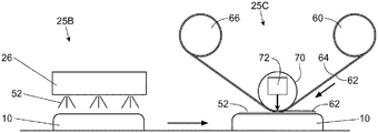
図6Aは、物品10に接着剤52を堆積させる第1の工程を実施するためのステーション25Bを示す。接着剤52は、UV硬化性、感圧性、又は両方が挙げられるがこれらに限定されない、任意の好適なタイプのものであってよい。接着剤52は、任意の好適な方法で塗布することができる。場合によっては、接着剤の精密な位置のためにインクジェット印刷プロセスによってなどデジタルアプリケーションプロセスによって接着剤52を堆積させることが所望されることがある。これは、ステーション25Aで使用されるものと類似したインクジェットプリントヘッド26を使用することによって実行することができる。
FIG. 6A shows a
図6Aはまた、コールド箔プロセスの第2のステーション25Cの一実施形態も示す。第2のステーション25Cにおいて装置は、裏材64の上に金属性物質62を含む巻き出しロール60、巻き取りロール66、感圧性接着剤を使用した場合は裏材64とその上の金属性物質62を共に物品(複数可)に押し付けるためのロール70、及びUV硬化性接着剤を物品(複数可)に塗布した場合は接着剤を少なくとも部分的に硬化させるためのデバイス72を備える。第2のステーション25Cにおける工程は、2)接着剤の上に金属箔を押し付ける工程、3)接着剤を少なくとも部分的に硬化させる工程(硬化性接着剤を使用した場合)、及び4)接着剤を堆積させたところに金属性効果を残すために、箔及びあらゆる未転写の金属を除去する工程、のうち1つ又は2つ以上を含み得る。
FIG. 6A also illustrates one embodiment of the
図6Bは、同様であるが、工程(2)〜(4)を実施するコールド箔プロセスの第2のステーション25Cの別の実施形態によるステーション25Bを示す。図6Bに示す実施形態は、図6Aに示す実施形態とは圧盤74が位置決めロール76と78との間に位置する点で異なる。圧盤74は、次のように、箔62を接着剤52の上に押し付けるために使用される。1)物品10を接着剤と共に圧盤74の下に割出し動作する、2)圧盤74が物品10上の接着剤52の上に箔62を押し付けながら物品10に向かって移動する、3)接着は、UV接着剤を硬化させること、又は高い粘着特性を既に有する接着剤の性質のいずれかによって、箔62と物品10との間に得られる、4)接着剤52を塗布したところに金属性効果を残してフィルムキャリア64及びあらゆる未転写の金属を除去する。
FIG. 6B shows a
所望される所定の画像を物品(複数可)10に適用した後、物品のバッチにおける物品(複数可)は、さらなる処理のためにコンベヤー24によって別のコンベヤー又は装置へ運ばれてもよい。例えば、物品(複数可)10がボトルである場合、ボトルは、コンベヤー24から充填装置、及びふた締め機へ運ばれてもよい。
After applying the desired predetermined image (s) to the article (s) 10, the article (s) in the batch of articles may be conveyed by the
本明細書で開示する寸法及び値は、列挙された正確な数値に厳密に限られるとして理解されるべきではない。それよりむしろ、特に指示がない限り、このような寸法はそれぞれ、列挙された値とその値を囲む機能的に同等な範囲との両方を意味することを意図する。例えば、「90°」として開示される寸法は、「約90°」を意味するものとする。 The dimensions and values disclosed herein are not to be understood as being strictly limited to the exact numerical values recited. Instead, unless otherwise indicated, each such dimension is intended to mean both the recited value and a functionally equivalent range surrounding that value. For example, a dimension disclosed as “90 °” shall mean “about 90 °”.
本明細書の全体を通じて与えられる全ての最大数値限定は、それよりも小さい全ての数値限定を、そのようなより小さい数値限定があたかも本明細書に明確に記載されているかのように包含するものと理解すべきである。本明細書の全体を通じて与えられる全ての最小数値限定は、それより大きい全ての数値限定を、そのようなより大きい数値限定があたかも本明細書に明確に記載されているかのように包含する。本明細書全体を通して与えられる全ての数値範囲は、そのようなより広い数値範囲内に入るそれよりも狭い全ての数値範囲を、そのような狭い数値範囲があたかも全て本明細書に明確に記載されているかのように包含する。 All maximum numerical limits given throughout this specification are intended to include all lower numerical limits as if such lower numerical limits were expressly set forth herein. Should be understood. All minimum numerical limits given throughout this specification include all higher numerical limits as if such higher numerical limits were expressly set forth herein. All numerical ranges given throughout this specification are expressly set forth herein as if all such narrow numerical ranges were narrower than those falling within such wider numerical ranges. Include as if.
発明を実施するための形態において引用された全ての文献は、関連部分において参照により本明細書に組み込まれている。いかなる文献の引用も、本発明に関する先行技術であることを認めるものとして解釈されるべきではない。本明細書における用語のいずれかの意味又は定義が、参照により組み込まれる文献における用語のいずれかの意味又は定義と対立する範囲においては、本明細書においてその用語に付与した意味又は定義を適用するものとする。 All documents cited in the detailed description are hereby incorporated by reference in the relevant part. Citation of any document should not be construed as an admission that it is prior art with respect to the present invention. To the extent that any meaning or definition of a term in this specification conflicts with any meaning or definition of a term in a document incorporated by reference, the meaning or definition given to that term in this specification applies. Shall.
本発明の特定の実施形態が説明及び記載されてきたが、本発明の趣旨及び範囲から逸脱することなく他の様々な変更及び修正を実施できることが当業者には自明であろう。したがって、本発明の範囲内に含まれるそのような全ての変更及び修正は、添付の特許請求の範囲によって網羅されることが意図される。 While particular embodiments of the present invention have been illustrated and described, it would be obvious to those skilled in the art that various other changes and modifications can be made without departing from the spirit and scope of the invention. Accordingly, all such changes and modifications included within the scope of this invention are intended to be covered by the appended claims.
Claims (10)
少なくとも1つの装飾デバイスを提供する工程と、
非接触物質堆積デバイスを提供する工程と、
表面を有する少なくとも1つの三次元の物品を提供する工程と、
前記装飾デバイス及び前記物質堆積デバイスを通過する前記物品を移送するためのコンベヤーを提供する工程と、
前記装飾デバイスによって前記物品に装飾効果を提供する工程と、を含む方法によって作製され、前記方法は、さらに、
前記物品が前記物質堆積デバイスを少なくとも2回通過するように、前記物品と前記物質堆積デバイスとの間に再循環する相対運動を生じさせる工程と、
前記相対運動中に、前記物質堆積デバイスを使用することによって前記物品の前記表面の少なくとも一部の上に物質を堆積させる工程であって、各パスにおいて、前記堆積デバイスは、形成される所定のパターン全体の一部のみを堆積させ、前記所定のパターンを形成するために前記物品が前記物質堆積デバイスを少なくとも2回通過する工程を含むことを特徴とする、物品。 An article having a substance deposited thereon in a predetermined pattern, the article comprising:
Providing at least one decorative device;
Providing a non-contact material deposition device;
Providing at least one three-dimensional article having a surface;
Providing a conveyor for transporting the article passing through the decoration device and the material deposition device;
Providing a decorative effect to the article by the decorative device, the method further comprising:
Creating a recirculating relative motion between the article and the material deposition device such that the article passes through the material deposition device at least twice;
Depositing material on at least a portion of the surface of the article by using the material deposition device during the relative motion, wherein in each pass, the deposition device is An article comprising depositing only a portion of an entire pattern and passing the article through the material deposition device at least twice to form the predetermined pattern.
Applications Claiming Priority (5)
| Application Number | Priority Date | Filing Date | Title |
|---|---|---|---|
| US201462078990P | 2014-11-13 | 2014-11-13 | |
| US62/078,990 | 2014-11-13 | ||
| US201562211993P | 2015-08-31 | 2015-08-31 | |
| US62/211,993 | 2015-08-31 | ||
| PCT/US2015/059682 WO2016077204A1 (en) | 2014-11-13 | 2015-11-09 | Digitally printed and decorated article |
Publications (1)
| Publication Number | Publication Date |
|---|---|
| JP2017536304A true JP2017536304A (en) | 2017-12-07 |
Family
ID=54695845
Family Applications (1)
| Application Number | Title | Priority Date | Filing Date |
|---|---|---|---|
| JP2017525628A Pending JP2017536304A (en) | 2014-11-13 | 2015-11-09 | Articles printed and decorated digitally |
Country Status (7)
| Country | Link |
|---|---|
| US (1) | US20160136969A1 (en) |
| EP (1) | EP3218200A1 (en) |
| JP (1) | JP2017536304A (en) |
| CN (1) | CN107073992A (en) |
| CA (1) | CA2964486A1 (en) |
| MX (1) | MX2017005991A (en) |
| WO (1) | WO2016077204A1 (en) |
Families Citing this family (12)
| Publication number | Priority date | Publication date | Assignee | Title |
|---|---|---|---|---|
| US9925678B2 (en) | 2014-12-30 | 2018-03-27 | The Gillette Company Llc | Razor blade with a printed object |
| US10315323B2 (en) | 2015-01-08 | 2019-06-11 | The Gillette Company Llc | Razor cartridge with a printed lubrication control member |
| US20160199992A1 (en) * | 2015-01-08 | 2016-07-14 | The Gillette Company | Razor cartridge with a printed lubrication member |
| US10675772B2 (en) | 2016-06-29 | 2020-06-09 | The Gillette Company Llc | Printed lubricious material disposed on razor blades |
| US10384360B2 (en) | 2016-06-29 | 2019-08-20 | The Gillette Company Llc | Razor blade with a printed object |
| WO2018008315A1 (en) | 2016-07-08 | 2018-01-11 | 昭和アルミニウム缶株式会社 | Printing apparatus and can body manufacturing system |
| JP6745229B2 (en) * | 2016-07-08 | 2020-08-26 | 昭和アルミニウム缶株式会社 | Printer |
| DE102017112259B3 (en) * | 2017-06-02 | 2018-08-23 | Isimat Gmbh Siebdruckmaschinen | Device and method for decorating objects |
| CN111225799B (en) | 2017-09-19 | 2022-06-03 | 鲍尔公司 | Container decorating apparatus and method |
| JP7123556B2 (en) | 2017-12-27 | 2022-08-23 | アルテミラ株式会社 | printer |
| CN109435488A (en) * | 2018-12-07 | 2019-03-08 | 上海宇田机电设备有限公司 | Bottle cap double-sided stamp device |
| CN111546762B (en) * | 2019-02-12 | 2022-04-19 | 宝洁公司 | Method and apparatus for applying material to articles using a transfer member |
Citations (5)
| Publication number | Priority date | Publication date | Assignee | Title |
|---|---|---|---|---|
| US20040252174A1 (en) * | 2001-06-27 | 2004-12-16 | Baxter William Ronald Stuart | Printing apparatus and method |
| JP2008162645A (en) * | 2006-12-28 | 2008-07-17 | Koa Glass Kk | Manufacturing process of painting glass container |
| JP3148944U (en) * | 2008-12-22 | 2009-03-05 | 株式会社トーヨー工芸工業 | Full surface hot stamp tube container and its alignment device |
| JP2010510141A (en) * | 2006-11-22 | 2010-04-02 | プラスチパック パッケージング,インコーポレイテッド | Digital printing of plastic containers |
| US20110126413A1 (en) * | 2009-12-02 | 2011-06-02 | Andrew Anthony Szczepanowski | Razor cartridge components with indicia |
Family Cites Families (21)
| Publication number | Priority date | Publication date | Assignee | Title |
|---|---|---|---|---|
| CA2131424C (en) * | 1993-09-30 | 2000-01-18 | Masami Ikeda | Image forming method, process for producing decorative aluminum plate, apparatus for carrying out the process, decorative aluminum plate, and recording medium |
| BR9707189A (en) | 1996-01-26 | 1999-04-06 | Tetra Laval Holdings & Finance | Method and apparatus for printing images on packaging material |
| US6209459B1 (en) * | 1998-01-16 | 2001-04-03 | Blount, Inc. | Method for etching characters on bullets and bullets made by the method |
| US6699352B2 (en) | 1999-01-25 | 2004-03-02 | Henry Sawatsky | Decorative and protective system for wares |
| CN100429082C (en) * | 2004-12-08 | 2008-10-29 | 成都清洋包装印务有限责任公司 | Printed matter with decorative or anti false marks and hot transfer printing method, hot transfer printing equipment |
| US7210408B2 (en) * | 2004-12-30 | 2007-05-01 | Plastipak Packaging, Inc. | Printing plastic containers with digital images |
| US8522989B2 (en) | 2006-05-09 | 2013-09-03 | Plastipak Packaging, Inc. | Plastic containers with a base coat thereon |
| WO2009018892A1 (en) | 2007-08-03 | 2009-02-12 | Khs Ag | Device for printing containers |
| DE102008049241A1 (en) * | 2008-09-26 | 2010-04-08 | Khs Ag | Device for applying in each case a multiple printing on packaging |
| US20100086753A1 (en) * | 2008-10-02 | 2010-04-08 | Wade Johnson | Foiled articles and methods of making same |
| MX2011004208A (en) * | 2008-10-20 | 2011-05-24 | Plastipak Packaging Inc | Digital printing plastic containers with improved adhesion and recyclability. |
| DE102009013477B4 (en) | 2009-03-19 | 2012-01-12 | Khs Gmbh | Printing device for printing on bottles or similar containers |
| CN101941327A (en) * | 2010-07-02 | 2011-01-12 | 天津长荣印刷设备股份有限公司 | Digital ink-jet transfer-printing equipment and operating method thereof |
| US20120031548A1 (en) | 2010-08-06 | 2012-02-09 | Broad Gavin J | Apparatus and Method for Applying a Label to a Non-ruled Surface |
| US9403064B2 (en) * | 2011-12-22 | 2016-08-02 | Nike, Inc. | Golf ball with indicia printed under topcoat |
| CN104487609A (en) * | 2012-04-01 | 2015-04-01 | 盖尔创尼克斯有限公司 | Printing method for printing and plating process |
| DE102013205232A1 (en) | 2013-03-25 | 2014-09-25 | Krones Ag | Printing device for printing on containers |
| EP2786878A1 (en) * | 2013-04-04 | 2014-10-08 | Hewlett-Packard Industrial Printing Ltd. | Methods for printing articles |
| DE102013207799A1 (en) * | 2013-04-29 | 2014-10-30 | Krones Ag | Direct printing method for printing on plastic containers with cover layer |
| US20150009666A1 (en) * | 2013-07-03 | 2015-01-08 | Cordelia Lighting, Inc. | Universal led light kit |
| DE102013110103A1 (en) | 2013-09-13 | 2015-03-19 | Till Gmbh | Apparatus for printing rotationally asymmetrical containers |
-
2015
- 2015-11-09 JP JP2017525628A patent/JP2017536304A/en active Pending
- 2015-11-09 WO PCT/US2015/059682 patent/WO2016077204A1/en active Application Filing
- 2015-11-09 EP EP15798295.0A patent/EP3218200A1/en not_active Withdrawn
- 2015-11-09 CN CN201580060872.XA patent/CN107073992A/en active Pending
- 2015-11-09 MX MX2017005991A patent/MX2017005991A/en unknown
- 2015-11-09 US US14/935,474 patent/US20160136969A1/en not_active Abandoned
- 2015-11-09 CA CA2964486A patent/CA2964486A1/en not_active Abandoned
Patent Citations (5)
| Publication number | Priority date | Publication date | Assignee | Title |
|---|---|---|---|---|
| US20040252174A1 (en) * | 2001-06-27 | 2004-12-16 | Baxter William Ronald Stuart | Printing apparatus and method |
| JP2010510141A (en) * | 2006-11-22 | 2010-04-02 | プラスチパック パッケージング,インコーポレイテッド | Digital printing of plastic containers |
| JP2008162645A (en) * | 2006-12-28 | 2008-07-17 | Koa Glass Kk | Manufacturing process of painting glass container |
| JP3148944U (en) * | 2008-12-22 | 2009-03-05 | 株式会社トーヨー工芸工業 | Full surface hot stamp tube container and its alignment device |
| US20110126413A1 (en) * | 2009-12-02 | 2011-06-02 | Andrew Anthony Szczepanowski | Razor cartridge components with indicia |
Also Published As
| Publication number | Publication date |
|---|---|
| CN107073992A (en) | 2017-08-18 |
| WO2016077204A1 (en) | 2016-05-19 |
| EP3218200A1 (en) | 2017-09-20 |
| US20160136969A1 (en) | 2016-05-19 |
| MX2017005991A (en) | 2017-06-29 |
| CA2964486A1 (en) | 2016-05-19 |
Similar Documents
| Publication | Publication Date | Title |
|---|---|---|
| JP2017536304A (en) | Articles printed and decorated digitally | |
| JP2017535455A (en) | Process for decorating articles | |
| US10252544B2 (en) | Apparatus and method for depositing a substance on articles | |
| EP3218201B1 (en) | Digitally printed article | |
| CN109311313A (en) | Device for being printed on three-dimensional article | |
| CA2301917A1 (en) | Application of substances on a package | |
| US11491803B2 (en) | Method and apparatus for applying a material onto articles using a transfer component | |
| US20170056918A1 (en) | Parallel Motion Method for Depositing a Substance on Articles | |
| US20170056900A1 (en) | Parallel Motion Apparatus for Depositing a Substance on Articles |
Legal Events
| Date | Code | Title | Description |
|---|---|---|---|
| A977 | Report on retrieval |
Free format text: JAPANESE INTERMEDIATE CODE: A971007 Effective date: 20180322 |
|
| A131 | Notification of reasons for refusal |
Free format text: JAPANESE INTERMEDIATE CODE: A131 Effective date: 20180327 |
|
| A521 | Request for written amendment filed |
Free format text: JAPANESE INTERMEDIATE CODE: A523 Effective date: 20180612 |
|
| A131 | Notification of reasons for refusal |
Free format text: JAPANESE INTERMEDIATE CODE: A131 Effective date: 20181023 |
|
| A02 | Decision of refusal |
Free format text: JAPANESE INTERMEDIATE CODE: A02 Effective date: 20190521 |