JP2017520316A - Grid calibration system for interventional procedures - Google Patents
Grid calibration system for interventional procedures Download PDFInfo
- Publication number
- JP2017520316A JP2017520316A JP2016574973A JP2016574973A JP2017520316A JP 2017520316 A JP2017520316 A JP 2017520316A JP 2016574973 A JP2016574973 A JP 2016574973A JP 2016574973 A JP2016574973 A JP 2016574973A JP 2017520316 A JP2017520316 A JP 2017520316A
- Authority
- JP
- Japan
- Prior art keywords
- grid
- tracking
- calibration
- tool
- image
- Prior art date
- Legal status (The legal status is an assumption and is not a legal conclusion. Google has not performed a legal analysis and makes no representation as to the accuracy of the status listed.)
- Pending
Links
Images


Classifications
-
- A—HUMAN NECESSITIES
- A61—MEDICAL OR VETERINARY SCIENCE; HYGIENE
- A61B—DIAGNOSIS; SURGERY; IDENTIFICATION
- A61B8/00—Diagnosis using ultrasonic, sonic or infrasonic waves
- A61B8/12—Diagnosis using ultrasonic, sonic or infrasonic waves in body cavities or body tracts, e.g. by using catheters
-
- A—HUMAN NECESSITIES
- A61—MEDICAL OR VETERINARY SCIENCE; HYGIENE
- A61B—DIAGNOSIS; SURGERY; IDENTIFICATION
- A61B17/00—Surgical instruments, devices or methods, e.g. tourniquets
- A61B17/00234—Surgical instruments, devices or methods, e.g. tourniquets for minimally invasive surgery
-
- A—HUMAN NECESSITIES
- A61—MEDICAL OR VETERINARY SCIENCE; HYGIENE
- A61B—DIAGNOSIS; SURGERY; IDENTIFICATION
- A61B34/00—Computer-aided surgery; Manipulators or robots specially adapted for use in surgery
- A61B34/20—Surgical navigation systems; Devices for tracking or guiding surgical instruments, e.g. for frameless stereotaxis
-
- A—HUMAN NECESSITIES
- A61—MEDICAL OR VETERINARY SCIENCE; HYGIENE
- A61B—DIAGNOSIS; SURGERY; IDENTIFICATION
- A61B8/00—Diagnosis using ultrasonic, sonic or infrasonic waves
- A61B8/42—Details of probe positioning or probe attachment to the patient
- A61B8/4209—Details of probe positioning or probe attachment to the patient by using holders, e.g. positioning frames
-
- A—HUMAN NECESSITIES
- A61—MEDICAL OR VETERINARY SCIENCE; HYGIENE
- A61B—DIAGNOSIS; SURGERY; IDENTIFICATION
- A61B8/00—Diagnosis using ultrasonic, sonic or infrasonic waves
- A61B8/42—Details of probe positioning or probe attachment to the patient
- A61B8/4245—Details of probe positioning or probe attachment to the patient involving determining the position of the probe, e.g. with respect to an external reference frame or to the patient
- A61B8/4263—Details of probe positioning or probe attachment to the patient involving determining the position of the probe, e.g. with respect to an external reference frame or to the patient using sensors not mounted on the probe, e.g. mounted on an external reference frame
-
- A—HUMAN NECESSITIES
- A61—MEDICAL OR VETERINARY SCIENCE; HYGIENE
- A61B—DIAGNOSIS; SURGERY; IDENTIFICATION
- A61B8/00—Diagnosis using ultrasonic, sonic or infrasonic waves
- A61B8/58—Testing, adjusting or calibrating the diagnostic device
- A61B8/587—Calibration phantoms
-
- A—HUMAN NECESSITIES
- A61—MEDICAL OR VETERINARY SCIENCE; HYGIENE
- A61N—ELECTROTHERAPY; MAGNETOTHERAPY; RADIATION THERAPY; ULTRASOUND THERAPY
- A61N5/00—Radiation therapy
- A61N5/10—X-ray therapy; Gamma-ray therapy; Particle-irradiation therapy
- A61N5/1001—X-ray therapy; Gamma-ray therapy; Particle-irradiation therapy using radiation sources introduced into or applied onto the body; brachytherapy
- A61N5/1007—Arrangements or means for the introduction of sources into the body
-
- A—HUMAN NECESSITIES
- A61—MEDICAL OR VETERINARY SCIENCE; HYGIENE
- A61N—ELECTROTHERAPY; MAGNETOTHERAPY; RADIATION THERAPY; ULTRASOUND THERAPY
- A61N5/00—Radiation therapy
- A61N5/10—X-ray therapy; Gamma-ray therapy; Particle-irradiation therapy
- A61N5/1001—X-ray therapy; Gamma-ray therapy; Particle-irradiation therapy using radiation sources introduced into or applied onto the body; brachytherapy
- A61N5/1027—Interstitial radiation therapy
-
- A—HUMAN NECESSITIES
- A61—MEDICAL OR VETERINARY SCIENCE; HYGIENE
- A61N—ELECTROTHERAPY; MAGNETOTHERAPY; RADIATION THERAPY; ULTRASOUND THERAPY
- A61N5/00—Radiation therapy
- A61N5/10—X-ray therapy; Gamma-ray therapy; Particle-irradiation therapy
- A61N5/1048—Monitoring, verifying, controlling systems and methods
- A61N5/1075—Monitoring, verifying, controlling systems and methods for testing, calibrating, or quality assurance of the radiation treatment apparatus
-
- A—HUMAN NECESSITIES
- A61—MEDICAL OR VETERINARY SCIENCE; HYGIENE
- A61B—DIAGNOSIS; SURGERY; IDENTIFICATION
- A61B17/00—Surgical instruments, devices or methods, e.g. tourniquets
- A61B17/00234—Surgical instruments, devices or methods, e.g. tourniquets for minimally invasive surgery
- A61B2017/00238—Type of minimally invasive operation
- A61B2017/00274—Prostate operation, e.g. prostatectomy, turp, bhp treatment
-
- A—HUMAN NECESSITIES
- A61—MEDICAL OR VETERINARY SCIENCE; HYGIENE
- A61B—DIAGNOSIS; SURGERY; IDENTIFICATION
- A61B34/00—Computer-aided surgery; Manipulators or robots specially adapted for use in surgery
- A61B34/20—Surgical navigation systems; Devices for tracking or guiding surgical instruments, e.g. for frameless stereotaxis
- A61B2034/2046—Tracking techniques
- A61B2034/2051—Electromagnetic tracking systems
-
- A—HUMAN NECESSITIES
- A61—MEDICAL OR VETERINARY SCIENCE; HYGIENE
- A61N—ELECTROTHERAPY; MAGNETOTHERAPY; RADIATION THERAPY; ULTRASOUND THERAPY
- A61N5/00—Radiation therapy
- A61N5/10—X-ray therapy; Gamma-ray therapy; Particle-irradiation therapy
- A61N5/1001—X-ray therapy; Gamma-ray therapy; Particle-irradiation therapy using radiation sources introduced into or applied onto the body; brachytherapy
- A61N5/1007—Arrangements or means for the introduction of sources into the body
- A61N2005/1012—Templates or grids for guiding the introduction of sources
Abstract
グリッド較正システムは、1又は複数の介入ツールを有する介入機器23と、較正領域内で介入ツール23を支持しガイドするための孔マトリクスを有するグリッド22と、グリッド22に対して位置付けられ、較正領域内の介入ツール23を示すツール画像を生成するイメージング装置24と、を用いる。グリッド較正システムは更に、ツール画像と、グリッドの孔マトリクスを表す点マトリクスを有する仮想グリッドとの画像位置合わせから導き出される、グリッド22及びイメージング装置24の相対的な位置付けの任意のアライメント調整を表示するために、グリッド較正ワークステーション40を用いる。The grid calibration system is positioned relative to the grid 22 with an interventional instrument 23 having one or more intervention tools, a grid 22 with a hole matrix for supporting and guiding the intervention tool 23 within the calibration area, and a calibration area. An imaging device 24 for generating a tool image showing the intervention tool 23 therein. The grid calibration system further displays any alignment adjustment of the relative positioning of the grid 22 and the imaging device 24 derived from image alignment of the tool image and a virtual grid having a point matrix that represents the hole matrix of the grid. For this purpose, a grid calibration workstation 40 is used.
Description
本発明は、概して、介入プロシージャ(例えば、前立腺ブラキセラピープロシージャ)に組み込まれるグリッド較正システムに関する。本発明は、特に、介入プロシージャの最中、超音波プローブのイメージング平面に対し、解剖学的関心領域内で介入ツール(例えば、カテーテル、ニードル、その他)を支持しガイドするためのグリッド(テンプレートとしても知られる)の較正に関する。 The present invention relates generally to grid calibration systems that are incorporated into interventional procedures (eg, prostate brachytherapy procedures). In particular, the present invention provides a grid (as a template) for supporting and guiding interventional tools (eg, catheters, needles, etc.) within the anatomical region of interest relative to the imaging plane of the ultrasound probe during the interventional procedure. Also known).
前立腺癌は、最も一般的な非皮膚関連の癌であり、アメリカ人男性の癌死亡の第2の主要な原因である。男性の6人に1人に影響を及ぼし、前立腺癌の約238,000の新しい症例が2013年に診断されており、そのうち30,000は命にかかわるものである。ブラキセラピーは、高線量レート(「HDR」)及び低線量レート(「LDR」)プロシージャによって、前立腺癌を治療するために使用される一般的な放射線治療である。概して、HDR前立腺ブラキセラピーは、前立腺への10−20のカテーテルの経会陰的挿入と、その後の、リモートアフターローダを使用したこれらのカテーテル内への放射性線源の順次の挿入とを含む。これに対して、LDR前立腺ブラキセラピーは、前立腺に挿入される多数のニードルを通じて供給される約100の放射性シードの前立腺内への永続的な埋め込みを含む。 Prostate cancer is the most common non-skin-related cancer and the second leading cause of cancer death in American men. Affecting one in six men, approximately 238,000 new cases of prostate cancer were diagnosed in 2013, of which 30,000 are life-threatening. Brachytherapy is a common radiation therapy used to treat prostate cancer through high dose rate (“HDR”) and low dose rate (“LDR”) procedures. In general, HDR prostate brachytherapy involves transperineal insertion of 10-20 catheters into the prostate, followed by sequential insertion of radioactive sources into these catheters using a remote afterloader. In contrast, LDR prostate brachytherapy involves the permanent implantation of about 100 radioactive seeds delivered through a number of needles inserted into the prostate into the prostate.
HDR及びLDR前立腺ブラキセラピープロシージャの両方並びに他の前立腺プロシージャ(例えば、経会陰的前立腺生検)に関して、カテーテル又はニードルは、グリッド/テンプレートを通じて一般に挿入され、グリッド/テンプレートは、会陰に対して位置付けられ、カテーテル又はニードルが前立腺に挿入されると、カテーテル又はニードルの均一な分布及び固定のための支援及びガイダンスを提供する。 For both HDR and LDR prostate brachytherapy procedures as well as other prostate procedures (eg, transperineal prostate biopsy), the catheter or needle is typically inserted through the grid / template and the grid / template is positioned relative to the perineum. Once the catheter or needle is inserted into the prostate, it provides assistance and guidance for uniform distribution and fixation of the catheter or needle.
例えば、図1は、カテーテル/ニードル23を含む典型的な前立腺ブラキセラピー機器セットアップ20を示す。具体的には、例示の前立腺ブラキセラピープロシージャは、セットアップ20全体に安定性を提供するためにステッパ21上にグリッド/テンプレート22と共に位置付けられる経直腸的超音波(「TRUS」)プローブ24を使用して、超音波ガイダンス中に実現される。グリッド/テンプレート22が適当な位置に保持され、TRUSプローブ24は、グリッド/テンプレート22に対しほぼ垂直な軸方向において並進し、軸方向を中心に回転することを可能にされる。カテーテル/ニードル23は、予め決められた計画に従って位置付けられ、又は前立腺10及び周囲器官のセグメント化とともに超音波画像において遡及的に識別され、カテーテル/ニードル23と器官セグメント化との間の相対的なジオメトリが、放射性シード(例えば放射性シード11)の線量分布及び特定の治療計画を決定するために使用される。
For example, FIG. 1 shows a typical prostate
超音波画像におけるエコーフラッシュによるカテーテル/ニードル23の手動識別は、例えば貧弱な画像品質、隠れている構造及びオペレータ経験のような要因により、エラーを被りやすい。これらの制限を克服し精度を改善するために、追跡システム30(例えば電磁(「EM」)追跡システム又は光学追跡システム)が、今日、HDR及びLDR前立腺ブラキセラピープロシージャに関して提案されている。特にEM追跡システムの場合、EMセンサ(図示せず)が、前立腺10及び周囲の解剖学的関心領域に対しカテーテル/ニードル23及びTRUSプローブ24をEM座標系内において正確に空間的に位置特定するために、カテーテル/ニードル23及びTRUSプローブ24の両方に組み込まれる。グリッド/テンプレート22が、追跡センサと一体化されることもでき、その一方、グリッド/テンプレート22が追跡センサと一体化されない場合、EM座標系内でグリッド/テンプレート22を位置特定する代替の方法は、EMグリッド較正の実施を含むことができ、この較正において、追跡されるカテーテル/ニードル23は、グリッド/テンプレート22の全体のマッピングを生成するために孔マトリクスのさまざまなロケーションに挿入される。EM座標系でのグリッド/テンプレート22の孔マトリクスのこの位置特定は、「EMグリッド」として知られる。
Manual identification of the catheter /
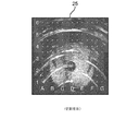
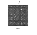
前立腺ブラキセラピープロシージャの最中、超音波スキャナの特定のモデルは、例えば図2に示す超音波画像25上の白色ドットの仮想グリッドのオーバレイのようなグリッド/テンプレート22の孔マトリクスのアライメントについて視覚的な支援を提供するために、TRUSプローブ24からの超音波画像上に「仮想グリッド」をオーバレイするフィーチャを具備する。これは、TRUSプローブ24の画像平面(図示せず)へのグリッド/テンプレート22の孔マトリクスの投影として役立つことを意味する。図2に例示的に示されるように、仮想グリッドは、超音波画像25へのMxNグリッド点の単純なオーバレイであり、選択された間隔(一般に5mm又は10mm)は、グリッド/テンプレート22の孔マトリクスのMxN孔及び間隔に一致し又はそれと等価である。正確な追跡のために、仮想グリッドに対する孔マトリクスグリッド/テンプレート22のアライメントは、オペレータによって手動で実施される。セットアップ20のためのこの較正は、一般に、水槽内でグリッド/テンプレート22の孔マトリクスにカテーテル/ニードルを挿入し、必要に応じてグリッド/テンプレート22の物理的な位置を調整することによって、ときどき(例えば毎日/毎週/毎月)行われ、それにより、仮想グリッドオーバレイは、TRUSプローブ24の画像平面におけるツールのエコーフラッシュによって表現されるように、グリッド/テンプレート22の孔マトリクスに最大限に一致するようになる。図3は、仮想グリッドに対するグリッド/テンプレート22の孔マトリクスの真のアライメントを表す超音波画像26内のC3及びE5ロケーションに対応する2つの超音波エコーを示す。しかしながら、実際、このような真のアライメントは、多くの前立腺ブラキセラピープロシージャの進行中にめったに達成されず及び/又は維持されない。
During the prostate brachytherapy procedure, a particular model of the ultrasound scanner is used for visualizing the pore matrix alignment of the grid /
今日、グリッド/テンプレート22の孔マトリクスを超音波仮想グリッドにアラインさせるためのグリッド較正のプロセスは、手動で行われており、オペレータによるアライメントの主観的な視覚的確認を必要とする。より具体的には、垂直方向及び/又は水平方向におけるグリッド/テンプレート22の並進並びにTRUSプローブ24の回転は、「試行錯誤」で調整され、これは、時間がかかり、オペレータ間で異なりやすい。こうして、従来技術における問題は、ステッパ21に対するグリッド/テンプレート22及びTRUSプローブ24の正確な位置付けのために必要とされるグリッド並進及び/又はプローブ回転の最適な組み合わせを決定し、図3に示されるように仮想グリッドオーバレイに対しグリッド/テンプレート22の孔マトリクスをアラインすることの難しさである。
Today, the process of grid calibration for aligning the pore matrix of the grid /
本発明は、グリッド/テンプレート(例えば図1に示されるグリッド/テンプレート22)の較正を助けるための自動化された品質保証方法を提案し、更にアライメントエラーの定量化を提供する。本発明は、仮想グリッドを通じてツールフラッシュ及び投影される超音波グリッド点のロケーションを自動的に検出するための画像識別方法の使用を含む。この情報から、仮想グリッドに対するグリッド/テンプレートの正確なアライメントのために必要とされる正確な並進及び/又は回転パラメータが、計算され、オペレータに表示されることができる。本発明は更に、グリッド/テンプレートと、仮想グリッド又は他のタイプの任意の外部グリッド基準(例えば図1に示される追跡システム30)との間の適合エラーを決定するために利用されることができる。
The present invention proposes an automated quality assurance method to help calibrate the grid / template (eg, the grid /
本発明の1つの形態は、1又は複数の介入ツール(例えばカテーテル又はニードル)を有する介入機器と、較正領域内において介入ツールを支持及びガイドするための孔マトリクスを有するグリッドと、グリッドに対して位置付けられ、較正領域内の介入ツールを示すツール画像を生成する超音波プローブと、を用いるグリッド較正システムである。 One form of the present invention includes an interventional instrument having one or more interventional tools (eg, catheters or needles), a grid having a hole matrix for supporting and guiding the interventional tool in the calibration region, and a grid A grid calibration system using an ultrasound probe that is positioned and generates a tool image showing an interventional tool in a calibration region.
グリッド較正システムは更に、ツール画像と、グリッドの孔マトリクスを表す点マトリクスを有する仮想グリッドとの画像位置合わせから導き出される、グリッド及び超音波プローブの相対的な位置付けのアライメント調整を表示するためにグリッド較正ワークステーションを用いる。 The grid calibration system further includes a grid to display the alignment adjustment of the relative positioning of the grid and the ultrasound probe, derived from the image alignment of the tool image and a virtual grid having a point matrix representing the hole matrix of the grid. Use a calibration workstation.
アライメント調整は、超音波プローブに対するグリッドの水平方向の並進調整、超音波プローブに対するグリッドの垂直方向の並進調整、及び/又はグリッドに対するプローブの回転調整を含むことができる。 The alignment adjustment can include a horizontal translation adjustment of the grid relative to the ultrasound probe, a vertical translation adjustment of the grid relative to the ultrasound probe, and / or a rotation adjustment of the probe relative to the grid.
単に並進調整のために、好適には、2又はより多くの介入ツールが、ツール画像を生成するために利用される。 For just translational adjustment, preferably two or more intervention tools are utilized to generate the tool image.
回転調整のために、好適には、3又はより多くの介入ツールが、ツール画像を生成するために利用される。 For rotational adjustment, preferably three or more intervention tools are utilized to generate the tool image.
グリッド較正ワークステーションは更に、仮想グリッドに対するツール画像のアライメント適合エラー(例えば最小2乗)を表示することができる。アライメント適合エラーは、アライメント適合エラーが対応する介入プロシージャ(例えばHDR又はLDR前立腺ブラキセラピープロシージャ)について許容できるか又は許容できないかを示す閾値に対して適用されることができる。 The grid calibration workstation may further display tool image alignment alignment errors (eg, least squares) relative to the virtual grid. The alignment fit error can be applied against a threshold that indicates whether the alignment fit error is acceptable or unacceptable for the corresponding interventional procedure (eg, HDR or LDR prostate brachytherapy procedure).
介入機器は更に、追跡システム(例えばEM追跡システム)を有することができ、追跡システムは、グリッドに対して位置付けられ、グリッドの孔マトリクスを表す追跡グリッドを生成するために介入ツール及び/又はグリッドと一体化されるセンサを有する。追跡グリッドの生成によって、グリッド較正ワークステーションは更に、仮想グリッドに対する追跡グリッドの仮想追跡適合エラー(例えば最小2乗)、及び/又はツール画像に対する追跡グリッドの画像追跡適合エラー(例えば最小2乗)を表示することができる。追跡適合エラーは、EM追跡システムの追跡の正確さが対応する介入プロシージャについて許容できるか又は許容できないかを示す閾値に対して適用されることができる。 The interventional device can further include a tracking system (eg, an EM tracking system) that is positioned relative to the grid and includes an interventional tool and / or grid to generate a tracking grid that represents the pore matrix of the grid. Has an integrated sensor. By generating the tracking grid, the grid calibration workstation can further generate a tracking grid virtual tracking adaptation error (eg, least squares) for the virtual grid and / or a tracking grid image tracking adaptation error (eg, least squares) for the tool image. Can be displayed. The tracking adaptation error can be applied to a threshold that indicates whether the tracking accuracy of the EM tracking system is acceptable or unacceptable for the corresponding intervention procedure.
本発明の上述の形態及び他の形態並びに本発明のさまざまな特徴及び効果は、添付の図面と関連して理解される本発明のさまざまな実施形態の以下の詳細な説明から一層明らかになる。詳細な説明及び図面は、本発明の単に説明するものであり、制限するものではなく、本発明の範囲は、添付の請求項及びその等価なものによって規定される。 The foregoing forms and other forms of the present invention, as well as various features and advantages of the present invention, will become more apparent from the following detailed description of various embodiments of the present invention understood in conjunction with the accompanying drawings. The detailed description and drawings are merely illustrative of the invention rather than limiting, the scope of the invention being defined by the appended claims and equivalents thereof.
本発明の理解を容易にするために、図4及び図5にそれぞれ示される本発明のグリッド較正システム及び方法の例示的な実施形態が、EM追跡システムによって追跡される介入ツールの超音波イメージングの状況において、ここに提供される。例示的な実施形態の記述から、当業者であれば、(1)追跡グリッドを除くベース較正方法について、(2)追跡グリッドを含む追跡較正方法について、(3)さまざまなタイプの介入ツール及びいずれの較正方法のためのグリッド、(4)いずれの較正方法のための代替のイメージング装置、及び(5)追跡較正方法のための代替追跡システム、に関して、本発明の動作原理を如何にしてグリッド較正システム/方法のインプリメンテーションに適用するかが分かるであろう。 To facilitate understanding of the present invention, exemplary embodiments of the grid calibration system and method of the present invention shown in FIGS. 4 and 5, respectively, are provided for ultrasound imaging of interventional tools tracked by an EM tracking system. In the situation provided here. From the description of the exemplary embodiments, those skilled in the art will recognize that (1) a base calibration method excluding a tracking grid, (2) a tracking calibration method including a tracking grid, (3) various types of intervention tools and any Grid calibration for any of the calibration methods, (4) alternative imaging device for any calibration method, and (5) alternative tracking system for the tracking calibration method. You will see how it applies to system / method implementations.
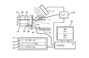
図4を参照して、図1の介入機器20は更に、水タンク/ファントム28の超音波画像27を容易にするために、当技術分野において知られているステッパ21のサポート29上に位置付けられる水タンク/ファントム28を用いる。EM追跡システムは、EM磁界生成器31、介入ツール23と一体化されるEMセンサ32、TRUSプローブ24と一体化されるEMセンサ(図示せず)、グリッド/テンプレート22と一体化される任意のEMセンサ、及び当分野において知られているツールトラッカ33を用いる。
Referring to FIG. 4, the
通常、動作中、1又は複数の介入ツール23は、グリッド/テンプレート22の孔マトリクスのさまざまな孔を通して挿入され、介入ツール23は、超音波画像27においてエコーフラッシュとして可視である。好適には、2又はより多くの介入ツール23のイメージングから、グリッド較正並進調整が、(1)TRUSプローブ24に対するグリッド/テンプレート22の高さ調整のための垂直方向におけるグリッド/テンプレート22の並進、及び(2)TRUSプローブ24に対するグリッド/テンプレート22の横方向調整のための水平方向におけるグリッド/テンプレート22の並進、に関して表示される。好適には3又はより多くの介入ツール23のイメージングから、グリッド較正回転調整が、グリッド/テンプレート22に対する超音波画像27の角度調整のために、時計回り又は反時計回りの方向におけるTRUSプローブ24の回転に関して表示される。この目的で、グリッド較正ワークステーション40は、ワークステーション40のハードウェア、ソフトウェア、ファームウェア及び/又は回路として構造的に構成されるモジュラネットワーク41を用いる。
Typically, in operation, one or
具体的には、モジュラネットワーク41は、グリッド/テンプレート22の孔マトリクスを通して挿入される介入ツール23の超音波画像27(以下「ツール画像27」)上への仮想グリッドオーバレイを有するグリッド較正画像(例えば図3に示されるGCI26)を生成するグリッド較正画像(「GCI」)生成器42を有する。
Specifically, the
実際、仮想グリッドオーバレイは、グリッド点のM×Nマトリクス(好適にはM≧2及びN≧2)の任意の形である。一実施形態において、GCI生成器42は、特にプリセットされた仮想グリッドの点の数及び間隔がグリッド/テンプレート22の孔マトリクスと同一でなく又は等価でない場合に、さまざまなプリセットされた仮想グリッドの中から選択するための又は特定の仮想グリッドを特定するためのインタフェースを、ワークステーション40のユーザに提供する。
In fact, the virtual grid overlay is any form of an M × N matrix of grid points (preferably M ≧ 2 and N ≧ 2). In one embodiment, the
モジュラネットワーク41は更に、仮想グリッドオーバレイとツール画像27との間の「ベストフィット(best fit、最良の適合)」を達成するために、グリッド/テンプレート22及びTRUSプローブ24の上述の並進及び/又は回転グリッド較正調整を計算するグリッドアライメント計算器43を有する。更に、グリッドアライメント計算器43は、(1)仮想グリッドオーバレイとツール画像27との間の「調整適合エラー」、(2)仮想グリッドオーバレイと当分野において知られているグリッド/テンプレート22の孔マトリクスのEMローカライゼーションを表わすEMグリッドとの間の「仮想追跡適合エラー」、及び/又は(3)ツール画像と当分野において知られているグリッド/テンプレート22の孔マトリクスのEMローカライゼーションを表すEMグリッドとの間の「画像追跡適合エラー」を計算することができる。
The
モジュラネットワーク41は更に、グリッド/テンプレート22の孔マトリクス及び仮想グリッドオーバレイのアライメントを達成するために、グリッド/テンプレート22が並進され、及び/又はTRUSプローブ24が回転されるとき、並進及び/又は回転グリッド較正調整のリアルタイム表示を生成するグリッド調整表示生成器44を有する。計算される場合、グリッド調整表示生成器44が更に、仮想グリッドオーバレイとツール画像27との間の調整適合エラー、仮想グリッドオーバレイとEMグリッドとの間の仮想追跡適合エラー、及び/又はツール画像とEMグリッドとの間の画像追跡適合エラーのリアルタイム表示を生成する。
The
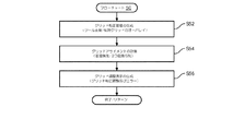
本発明の理解を容易にするために、フローチャート40によって実行される本発明のグリッド較正方法を表すフローチャート50が、以下に記述される。フローチャート50の記述は、グリッド較正目的のために6つの介入ツールを利用する状況におけるものであるが、当業者であれば、介入ツールの任意の数がこのようなグリッド較正目的のために使用されることができ、好適には3乃至7の介入ツールが使用されることが分かるであろう。
To facilitate understanding of the present invention, a
図5を参照して、フローチャート50のステージS52は、ツール画像上への仮想グリッドオーバレイを有するグリッド較正画像の、ワークステーション40による生成を含む。
Referring to FIG. 5, stage S52 of
図6に例示的に示される1つの実施形態において、TRUSプローブ24は、ロケーションA6、B2、D4、F3、G5及びH1においてグリッド/テンプレート22の6行×8列の孔マトリクスを通して挿入される6つの介入ツール23からの、6つのエコーフラッシュ(「EF」)点を有するツール画像60を生成するように動作される。ステージS52のフェーズP52aの最中、生成器42は、グリッド較正画像62を表示するために、ツール画像60上に仮想グリッド61をオーバレイする。任意には、6つの介入ツール23のEM追跡及び/又はグリッド/テンプレート22に基づいて、ステージS52のフェーズP52bの最中、生成器42は、グリッド較正画像62上にEM点の6行×8列のEMグリッド63をオーバレイして、グリッド較正画像64を形成する。この実施形態は、ツール画像60及び仮想グリッド61のアライメントが、2以上の行間隔及び/又は2以上の列間隔オフセットされている場合、有利であり、6つの介入ツールのEM座標が、オフセットを検出するために利用されることができる。
In one embodiment exemplarily shown in FIG. 6,
図5に戻って、フローチャート50のステージS54は、ツール画像60及び仮想グリッド61を最大限にアラインするためのグリッド較正調整の計算を含む。
Returning to FIG. 5, stage S54 of
図7に例示的に示される1つの実施形態において、計算器43(図4)は、フラッシュ画像65及び点マトリクス画像67を生成するために、当分野において知られているGCI62又はGCI64の画像識別/セグメント化アルゴリズムを実行する。その後、計算器43は、フラッシュ画像65に関連付けられる2D座標系66から、点マトリクス画像67に関連付けられる2D座標系68への、2次元(「2D」)変換マトリクス69を計算する。変換マトリクス69は、ツール画像60及び仮想グリッド61をアラインするために、現在の並進/回転位置から「ベストフィット」まで、グリッド/テンプレート22及び/又はTRUSプローブ24を調整するために必要な任意の並進及び/又は回転値を提供する。更に、「ベストフィット」が達成されると、変換マトリクス69は、ツール画像60と仮想グリッド61との間の調整適合エラー(例えば最小2乗)、EMグリッド63と仮想グリッド61との間の仮想追跡適合エラー、及び任意にはツール画像60とEMグリッド63との間のツール追跡適合エラー、の計算を容易にする。上述したように、グリッド/テンプレート22の現在ロケーションにおける追跡適合エラーは、EMグリッド63の忠実性を示し、従って、新しいEMグリッド較正が現在のグリッドロケーションにおいて実施される必要があるかどうかを示す。
In one embodiment exemplarily shown in FIG. 7, the calculator 43 (FIG. 4) uses the
図5に戻って、グリッド/テンプレート22及び/又はTRUSプローブ24は、「ベストフィット」を達成するように調整されるので、フローチャート50のステージS56は、必要とされる計算されたグリッド調整の、リアルタイムの表示を含む。
Returning to FIG. 5, since the grid /
図8に例示的に示される1つの実施形態において、ユーザインタフェース70は、ダイナミックグリッド較正画像71、グリッド/プローブ調整提示情報72及びグリッド較正エラー73を示す。
In one embodiment exemplarily shown in FIG. 8, the
ダイナミックグリッド較正画像71は、グリッド/テンプレート22及び/又はTRUSプローブ24の調整を強調表示し、例えば、調整前期間中の画像71のミスアライメントは、調整後期間中にアラインされるように示されている。
The dynamic
アライメントを達成することを支援するために、調整前期間中の提示情報72は、時計回り(「CW」)又は反時計回り(「CCW」)の方向においてTRUSプローブ24に必要とされる任意の計算された回転と、X方向及び/又はY方向においてグリッド/テンプレート22に必要とされる任意の計算された並進と、を提供する。同時に、提示情報73は、ツール画像60と仮想グリッド61との間の現在適合エラーFE1(「TGI vs VGI」)、及び/又はEMグリッド63と仮想グリッド61との間の現在適合エラーFE2(「EGI vs VGI」)を提供する。
In order to assist in achieving alignment, the
グリッド/テンプレート22及び/又はプローブ24が調整されるに従って、提示情報72及び73は、ツール画像60及び仮想グリッド61のアライメントを最大限に達成することを助けるために、リアルタイムに更新される。実際、提示情報72及び73は、大きい調整/適合エラー(例えば赤)及び軽微な調整/適合エラー(例えば緑)を示すためにカラーコード化されることができる。
As the grid /
更に実際に、ワークステーション40は、特定の閾値を超えている調整/適合エラーについて警告を提供することができ、ツール画像60と仮想グリッド61との間のいかなるオフセット(例えばTRUプローブ24に対するグリッド/テンプレート22の任意の回転)も、付加のエラー計算又は修正のために保存されることができ、そののち、追跡座標系が、必要に応じて修正されることができる。
Furthermore, in practice, the
図4−図8を参照して、当業者であれば、特にブラキセラピープロシージャに関する最適グリッド較正を非限定的な例として含む本発明の多くの利点がわかるであろう。 4-8, those skilled in the art will appreciate the many advantages of the present invention including, as a non-limiting example, optimal grid calibration, particularly with respect to the brachytherapy procedure.
更に、実際に、本発明のワークステーションの実施形態は、スタンドアロンのワークステーションであってもよく、又は、介入プロシージャ(例えば前立腺ブラキセラピー)を実施するための知られているワークステーションにソフトウェアソリューションとして統合されることもできる。 Further, in practice, the workstation embodiments of the present invention may be stand-alone workstations or integrated as a software solution into known workstations for performing interventional procedures (eg, prostate brachytherapy). Can also be done.
本発明のさまざまな実施形態が図示され記述されているが、当業者であれば、本願明細書に記述される本発明の実施形態は例示であり、本発明の真の範囲を逸脱することなく、さまざまな変形及び変更が行われることができるとともに、等価なものがその構成要素と置き換えられることができることが分かるであろう。更に、多くの変形が、本発明の教示を適応させるために、その中心的範囲を逸脱することなく実行されることができる。従って、本発明は、本発明を実施するために考えられる最良の形態として開示された特定の実施形態に制限されず、本発明は、添付の特許請求の範囲に入るすべての実施形態を含むことが意図される。 While various embodiments of the invention have been illustrated and described, those skilled in the art will appreciate that the embodiments of the invention described herein are exemplary and do not depart from the true scope of the invention. It will be understood that various modifications and changes can be made and equivalents can be substituted for the components. In addition, many modifications may be made without departing from its central scope in order to accommodate the teachings of the present invention. Accordingly, the invention is not limited to the specific embodiments disclosed as the best mode contemplated for carrying out the invention, and the invention includes all embodiments that fall within the scope of the appended claims. Is intended.
Claims (20)
較正領域内において前記少なくとも1つの介入ツールを支持しガイドするための孔マトリックスを有するグリッドと、
前記グリッドに対し位置付けられ、前記較正領域内の前記少なくとも1つの介入ツールを示すツール画像を生成するイメージング装置と、
前記イメージング装置と通信するとともに、前記ツール画像と前記グリッドの前記孔マトリックスを表す点マトリックスを有する仮想グリッドとの画像位置合わせから導き出される、前記グリッド及び前記イメージング装置の相対的な位置付けに対する較正調整を表示するグリッド較正ワークステーションと、
を有するグリッド較正システム。 An interventional instrument having at least one interventional tool;
A grid having a hole matrix for supporting and guiding the at least one interventional tool in a calibration region;
An imaging device that is positioned relative to the grid and that generates a tool image showing the at least one interventional tool in the calibration region;
Calibration adjustments relative to the relative positioning of the grid and the imaging device, derived from image alignment of the tool image and a virtual grid having a point matrix representing the hole matrix of the grid, in communication with the imaging device A grid calibration workstation to display;
Grid calibration system.
前記較正領域内の少なくとも1つの介入ツールを示すツール画像を生成するステップと、
前記ツール画像と、前記グリッドの前記孔マトリクスを表す点マトリクスを有する仮想グリッドとの画像位置合わせから導き出される、前記グリッド及び前記イメージング装置の相対的な位置付けに対する較正調整を表示するステップと、
を含むグリッド較正方法。 A grid calibration method for a grid having a hole matrix that supports and guides at least one interventional tool in a calibration region, and an imaging device positioned relative to the grid, comprising:
Generating a tool image showing at least one intervention tool in the calibration region;
Displaying calibration adjustments relative to the relative positioning of the grid and the imaging device, derived from image alignment of the tool image and a virtual grid having a point matrix representing the hole matrix of the grid;
Grid calibration method including:
前記追跡グリッドは、追跡座標系内の前記グリッド及び前記追跡座標系内の前記グリッドによって支持されガイドされる少なくとも1つの介入ツールの少なくとも一方の追跡を表す、請求項16に記載のグリッド較正方法。 Calculating and displaying a tracking grid virtual tracking fit error relative to the virtual grid;
The grid calibration method of claim 16, wherein the tracking grid represents tracking of at least one of the grid in a tracking coordinate system and at least one interventional tool supported and guided by the grid in the tracking coordinate system.
前記追跡グリッドは、追跡座標系内の前記グリッド及び前記追跡座標系内の前記グリッドによって支持されガイドされる少なくとも1つの介入ツールの少なくとも一方の追跡を表す、請求項16に記載のグリッド較正方法。 Calculating and displaying an image tracking fit error of the tracking grid for the tool image;
The grid calibration method of claim 16, wherein the tracking grid represents tracking of at least one of the grid in a tracking coordinate system and at least one interventional tool supported and guided by the grid in the tracking coordinate system.
Applications Claiming Priority (3)
| Application Number | Priority Date | Filing Date | Title |
|---|---|---|---|
| US201462023977P | 2014-07-14 | 2014-07-14 | |
| US62/023,977 | 2014-07-14 | ||
| PCT/IB2015/055201 WO2016009312A1 (en) | 2014-07-14 | 2015-07-09 | Grid calibration system for interventional procedures |
Publications (2)
| Publication Number | Publication Date |
|---|---|
| JP2017520316A true JP2017520316A (en) | 2017-07-27 |
| JP2017520316A5 JP2017520316A5 (en) | 2018-08-02 |
Family
ID=53969389
Family Applications (1)
| Application Number | Title | Priority Date | Filing Date |
|---|---|---|---|
| JP2016574973A Pending JP2017520316A (en) | 2014-07-14 | 2015-07-09 | Grid calibration system for interventional procedures |
Country Status (5)
| Country | Link |
|---|---|
| US (1) | US10369384B2 (en) |
| EP (1) | EP3169242A1 (en) |
| JP (1) | JP2017520316A (en) |
| CN (1) | CN106659477A (en) |
| WO (1) | WO2016009312A1 (en) |
Families Citing this family (8)
| Publication number | Priority date | Publication date | Assignee | Title |
|---|---|---|---|---|
| US10357326B1 (en) * | 2016-07-29 | 2019-07-23 | Devicor Medical Products, Inc. | MRI breast biopsy targeting grid and cube |
| US11464568B2 (en) * | 2017-05-10 | 2022-10-11 | Best Medical International, Inc. | Customizable saturation biopsy |
| IT201700067474A1 (en) * | 2017-06-16 | 2018-12-16 | Univ Cattolica Del Sacro Cuore | APPLICATOR DEVICE FOR INTERVENTISTIC RADIOTHERAPY (BRACHITHERAPY) AND PERINEAL INTERVENTION AND / OR DIAGNOSTIC PROCEDURES |
| JP7319248B2 (en) * | 2017-08-28 | 2023-08-01 | コーニンクレッカ フィリップス エヌ ヴェ | Automatic field-of-view update for position-tracking interventional devices |
| EP3962367A4 (en) | 2019-05-03 | 2023-01-11 | Neil Glossop | Systems, methods, and devices for registering and tracking organs during interventional procedures |
| DE102020102213A1 (en) * | 2020-01-30 | 2021-08-05 | Carl Zeiss Meditec Ag | Brachytherapy preparation method, brachytherapy method and brachytherapy system |
| US11797545B2 (en) | 2020-04-21 | 2023-10-24 | International Business Machines Corporation | Dynamically generating facets using graph partitioning |
| EP4243927A1 (en) * | 2020-11-12 | 2023-09-20 | Alpha Tau Medical Ltd. | Radiotherapy template assembly |
Citations (10)
| Publication number | Priority date | Publication date | Assignee | Title |
|---|---|---|---|---|
| JP2001346795A (en) * | 2000-06-07 | 2001-12-18 | Canon Inc | Method of evaluating alignment between x-ray source and scattered ray removing grid, and feedback method, feedback device, x-ray radiography and x-ray radiographic device |
| JP2004354257A (en) * | 2003-05-29 | 2004-12-16 | Olympus Corp | Calibration slippage correction device, and stereo camera and stereo camera system equipped with the device |
| JP2007000226A (en) * | 2005-06-22 | 2007-01-11 | Toshiba Corp | Medical image diagnostic apparatus |
| US20120302890A1 (en) * | 2011-05-26 | 2012-11-29 | David Strong | Cradle apparatus for a stepper to hold ultra-sound probe |
| WO2013144832A1 (en) * | 2012-03-29 | 2013-10-03 | Koninklijke Philips N.V. | Quality assurance system and method for navigation-assisted procedures |
| US20130274725A1 (en) * | 2010-12-23 | 2013-10-17 | Christian Rathjen | Device for processing material of a workpiece and method for calibrating such a device |
| WO2014013418A2 (en) * | 2012-07-17 | 2014-01-23 | Koninklijke Philips N.V. | Determination apparatus for determining the pose and shape of an introduction element |
| WO2014033583A1 (en) * | 2012-08-28 | 2014-03-06 | Koninklijke Philips N.V. | Interventional guidance system with integrated tracking setup |
| JP2014507247A (en) * | 2011-03-08 | 2014-03-27 | ケアストリーム ヘルス インク | Alignment apparatus for X-ray imaging system |
| US20140121501A1 (en) * | 2012-10-31 | 2014-05-01 | Queen's University At Kingston | Automated intraoperative ultrasound calibration |
Family Cites Families (4)
| Publication number | Priority date | Publication date | Assignee | Title |
|---|---|---|---|---|
| US6438401B1 (en) | 2000-04-28 | 2002-08-20 | Alpha Intervention Technology, Inc. | Indentification and quantification of needle displacement departures from treatment plan |
| JP5848762B2 (en) * | 2010-06-28 | 2016-01-27 | コーニンクレッカ フィリップス エヌ ヴェKoninklijke Philips N.V. | Real-time quality control of EM calibration |
| US10362967B2 (en) * | 2012-07-09 | 2019-07-30 | Covidien Lp | Systems and methods for missed breath detection and indication |
| EP2996587B1 (en) | 2013-03-28 | 2022-08-24 | Koninklijke Philips N.V. | Instrument localization in guided high dose rate brachytherapy |
-
2015
- 2015-07-09 WO PCT/IB2015/055201 patent/WO2016009312A1/en active Application Filing
- 2015-07-09 JP JP2016574973A patent/JP2017520316A/en active Pending
- 2015-07-09 US US15/324,765 patent/US10369384B2/en not_active Expired - Fee Related
- 2015-07-09 EP EP15754008.9A patent/EP3169242A1/en not_active Withdrawn
- 2015-07-09 CN CN201580038326.6A patent/CN106659477A/en active Pending
Patent Citations (10)
| Publication number | Priority date | Publication date | Assignee | Title |
|---|---|---|---|---|
| JP2001346795A (en) * | 2000-06-07 | 2001-12-18 | Canon Inc | Method of evaluating alignment between x-ray source and scattered ray removing grid, and feedback method, feedback device, x-ray radiography and x-ray radiographic device |
| JP2004354257A (en) * | 2003-05-29 | 2004-12-16 | Olympus Corp | Calibration slippage correction device, and stereo camera and stereo camera system equipped with the device |
| JP2007000226A (en) * | 2005-06-22 | 2007-01-11 | Toshiba Corp | Medical image diagnostic apparatus |
| US20130274725A1 (en) * | 2010-12-23 | 2013-10-17 | Christian Rathjen | Device for processing material of a workpiece and method for calibrating such a device |
| JP2014507247A (en) * | 2011-03-08 | 2014-03-27 | ケアストリーム ヘルス インク | Alignment apparatus for X-ray imaging system |
| US20120302890A1 (en) * | 2011-05-26 | 2012-11-29 | David Strong | Cradle apparatus for a stepper to hold ultra-sound probe |
| WO2013144832A1 (en) * | 2012-03-29 | 2013-10-03 | Koninklijke Philips N.V. | Quality assurance system and method for navigation-assisted procedures |
| WO2014013418A2 (en) * | 2012-07-17 | 2014-01-23 | Koninklijke Philips N.V. | Determination apparatus for determining the pose and shape of an introduction element |
| WO2014033583A1 (en) * | 2012-08-28 | 2014-03-06 | Koninklijke Philips N.V. | Interventional guidance system with integrated tracking setup |
| US20140121501A1 (en) * | 2012-10-31 | 2014-05-01 | Queen's University At Kingston | Automated intraoperative ultrasound calibration |
Also Published As
| Publication number | Publication date |
|---|---|
| WO2016009312A1 (en) | 2016-01-21 |
| US10369384B2 (en) | 2019-08-06 |
| CN106659477A (en) | 2017-05-10 |
| EP3169242A1 (en) | 2017-05-24 |
| US20170203128A1 (en) | 2017-07-20 |
Similar Documents
| Publication | Publication Date | Title |
|---|---|---|
| JP2017520316A (en) | Grid calibration system for interventional procedures | |
| US11633629B2 (en) | Method of calibration of a stereoscopic camera system for use with a radio therapy treatment apparatus | |
| Bharat et al. | Electromagnetic tracking for catheter reconstruction in ultrasound-guided high-dose-rate brachytherapy of the prostate | |
| US5778043A (en) | Radiation beam control system | |
| JP2016193222A (en) | Method and apparatus for analyzing images | |
| EP3148643B1 (en) | Systems for brachytherapy planning based on imaging data | |
| CN110227214B (en) | Radiotherapy positioning method based on positioning target | |
| US20180132821A1 (en) | Electromagnetic tracker based ultrasound probe calibration | |
| WO2009012577A1 (en) | Methods and systems for compensating for changes in anatomy of radiotherapy patients | |
| JP2008022896A (en) | Positioning system | |
| JP2017510349A (en) | Quality assurance and data linkage of electromagnetic tracking system | |
| CN109925054B (en) | Auxiliary method, device and system for determining target point path and readable storage medium | |
| Zheng et al. | A novel method for accurate needle-tip identification in trans-rectal ultrasound-based high-dose-rate prostate brachytherapy | |
| JP4614957B2 (en) | Use of magnetic resonance imaging to locate anatomical targets | |
| French et al. | Real-time dosimetry for prostate brachytherapy using TRUS and fluoroscopy | |
| Talbot et al. | A method for patient set-up guidance in radiotherapy using augmented reality | |
| CN114096990A (en) | Image registration method and device, radiotherapy equipment and computer-readable storage medium | |
| JP6526346B2 (en) | Brachytherapy system and method | |
| GB2589929A (en) | Calibration of radiotherapy apparatus | |
| CN217014241U (en) | Positioning apparatus and positioning system | |
| US20240123260A1 (en) | Method of calibration of a stereoscopic camera system for use with a radio therapy treatment apparatus | |
| CN110663083B (en) | Brachytherapy treatment planning system | |
| CN114949633A (en) | Patient positioning method and device, storage medium and computer equipment | |
| JP2022165419A (en) | X-ray transmission image analysis for evaluation of linac isocenter quality | |
| JP2019507648A (en) | Check patient positioning with MPRS and crosshairs |
Legal Events
| Date | Code | Title | Description |
|---|---|---|---|
| RD04 | Notification of resignation of power of attorney |
Free format text: JAPANESE INTERMEDIATE CODE: A7424 Effective date: 20170214 |
|
| A521 | Request for written amendment filed |
Free format text: JAPANESE INTERMEDIATE CODE: A523 Effective date: 20180622 |
|
| A621 | Written request for application examination |
Free format text: JAPANESE INTERMEDIATE CODE: A621 Effective date: 20180622 |
|
| A977 | Report on retrieval |
Free format text: JAPANESE INTERMEDIATE CODE: A971007 Effective date: 20190313 |
|
| A131 | Notification of reasons for refusal |
Free format text: JAPANESE INTERMEDIATE CODE: A131 Effective date: 20190418 |
|
| A601 | Written request for extension of time |
Free format text: JAPANESE INTERMEDIATE CODE: A601 Effective date: 20190717 |
|
| A521 | Request for written amendment filed |
Free format text: JAPANESE INTERMEDIATE CODE: A523 Effective date: 20191018 |
|
| A131 | Notification of reasons for refusal |
Free format text: JAPANESE INTERMEDIATE CODE: A131 Effective date: 20191203 |
|
| A02 | Decision of refusal |
Free format text: JAPANESE INTERMEDIATE CODE: A02 Effective date: 20200623 |