JP2017516227A - Geodesic drawing on curved surfaces - Google Patents
Geodesic drawing on curved surfaces Download PDFInfo
- Publication number
- JP2017516227A JP2017516227A JP2016567564A JP2016567564A JP2017516227A JP 2017516227 A JP2017516227 A JP 2017516227A JP 2016567564 A JP2016567564 A JP 2016567564A JP 2016567564 A JP2016567564 A JP 2016567564A JP 2017516227 A JP2017516227 A JP 2017516227A
- Authority
- JP
- Japan
- Prior art keywords
- geodetic
- curve
- cad model
- curves
- geodesic
- Prior art date
- Legal status (The legal status is an assumption and is not a legal conclusion. Google has not performed a legal analysis and makes no representation as to the accuracy of the status listed.)
- Ceased
Links
Images


Classifications
-
- G—PHYSICS
- G06—COMPUTING; CALCULATING OR COUNTING
- G06F—ELECTRIC DIGITAL DATA PROCESSING
- G06F30/00—Computer-aided design [CAD]
Abstract
測地編集を実施する方法および対応するシステムならびにコンピュータ読み取り可能媒体。方法には、少なくとも1つの三次元(3D)サーフェスを含む1つのCADモデル(1000)を受け取るステップ(1105)が含まれる。この方法には、第1の測地フィーチャ(1002)の編集をユーザから受け取るステップ(1110)と、この編集に応答して、CADモデルに対し階層ベースによる更新を実施するステップ(1115)が含まれ、このステップ(1115)には、第1の測地フィーチャに対する編集に基づき、CADモデルの少なくとも1つの他のフィーチャ(1004)に対し相応の編集を実施して、更新されたCADモデル(1050)を生成するステップが含まれる。さらにこの方法には、更新されたCADモデルを記憶するステップ(1120)が含まれる。Method and corresponding system and computer readable medium for performing geodetic editing. The method includes receiving (1105) a CAD model (1000) that includes at least one three-dimensional (3D) surface. The method includes receiving (1110) an edit of a first geodetic feature (1002) from a user and performing (1115) a hierarchy-based update to the CAD model in response to the edit. In this step (1115), based on the edit to the first geodetic feature, at least one other feature (1004) of the CAD model is subjected to a corresponding edit to obtain an updated CAD model (1050). Generating step is included. The method further includes storing (1120) the updated CAD model.
Description
本発明は、全般的に言えば、コンピュータ支援による設計、視覚化および製造システム、製品ライフサイクルマネージメント("PLM")システム、ならびに製品および他の項目のデータを管理する同等のシステム(これらをまとめて「製品データ管理」システムまたはPDMシステムと称する)に関する。 The present invention generally includes computer-aided design, visualization and manufacturing systems, product lifecycle management ("PLM") systems, and equivalent systems that manage data for products and other items (summarizing them). The product data management system or PDM system).
発明の背景
PDMシステムは、PLMおよび他のデータを管理する。この場合、改善されたシステムが望まれている。
BACKGROUND OF THE INVENTION A PDM system manages PLM and other data. In this case, an improved system is desired.
発明の概要
本発明による種々の実現形態には、測地編集を実施する方法および対応するシステムならびにコンピュータ読み取り可能媒体が含まれる。本発明による方法は、少なくとも1つの三次元(3D)サーフェスを含む1つのCADモデルを受け取るステップを含む。本発明による方法は、第1の測地フィーチャの編集をユーザから受け取り、この編集に応答して、CADモデルに対し階層ベースによる更新を実施するステップを含み、さらにこのステップは、第1の測地フィーチャに対する編集に基づき、CADモデルの少なくとも1つの他のフィーチャに対し相応の編集を実施して、更新されたCADモデルを生成するステップを含む。さらに本発明による方法は、更新されたCADモデルを記憶するステップを含む。
SUMMARY OF THE INVENTION Various implementations according to the present invention include methods and corresponding systems for performing geodetic editing and computer readable media. The method according to the present invention includes receiving a CAD model that includes at least one three-dimensional (3D) surface. The method according to the present invention includes receiving a first geodetic feature edit from a user and performing a hierarchy-based update to the CAD model in response to the edit, the step further comprising: A corresponding editing is performed on at least one other feature of the CAD model based on the editing to generate an updated CAD model. Furthermore, the method according to the invention comprises the step of storing an updated CAD model.
これまでの記載は、以下の詳細な説明を当業者がよりよく理解できるよう、本発明の特徴および技術的な利点をどちらかと言えば大雑把に略述したものである。各請求項の要旨を成す本発明のその他の特徴および利点については、あとで述べることにする。当業者であれば理解できるように、当業者は開示された着想や特定の実施形態を、本発明と同じ目的を成し遂げるための変更または異なる構造設計のベースとして、ただちに使用することができる。さらに当業者であれば、最も広い形態で開示した本発明の着想および範囲を逸脱することなく、かかる等価の構造を実現することもできる。 The foregoing has outlined rather broadly the features and technical advantages of the present invention in order that those skilled in the art may better understand the detailed description that follows. Additional features and advantages of the invention will be described hereinafter that form the subject of each claim. As those skilled in the art will appreciate, those skilled in the art can readily use the disclosed ideas and specific embodiments as a basis for modification or different structural designs to accomplish the same purpose as the present invention. Further, those skilled in the art can realize such an equivalent structure without departing from the concept and scope of the present invention disclosed in its broadest form.
以下の発明の詳細な説明に入る前に、本明細書全体を通して用いられるいくつかの用語や表現について、ここで定義しておくのがよいと思われる。「を含む」および「を有する」なる表現ならびにそれらの派生語は、制限のない包含を表す。「または」なる表現は、「および/または」の意味も含む。「と関連する」および「それと関連する」ならびにそれらの派生語は、「含む」、「の中に含まれる」、「と相互接続された」、「を含有する」、「の中に含有される」、「に接続する」または「と接続する」、「に結合する」または「と結合する」、「と連携可能である」、「と共働する」、「をはさむ」、「に並置する」、「のすぐ近くにある」、「に結び付けられる」または「と結び付けられる」、「を有する」、「の所有物である」等を意味する場合もある。さらに「コントローラ」なる用語は、ハードウェアで実装されていようと、ファームウェア、ソフトウェア、またはそれらのうち少なくとも2つの組み合わせで実装されていようと、少なくとも1つのオペレーションを制御する何らかのデバイス、システムまたはそれらの一部分を表す。さらにここで留意しておきたいのは、いずれかの特定のコントローラと結び付けられた機能を、ローカルであろうとリモートであろうと、集中させてもよいし分散させてもよい、ということである。いくつかの用語および表現に対する定義は、本明細書全体にわたって規定されるものであり、当業者であれば理解できるように、かかる定義は、大部分の事例ではないにしても数多くの事例において、ここで定義した用語および表現の以前の使用にも将来の使用にも適用される。いくつかの用語は、幅広い種類の実施形態を含むことができるけれども、添付の特許請求の範囲では、それらの用語が特定の実施形態に明確に制限されてもよい。 Before proceeding to the detailed description of the invention below, it is believed that some terms and expressions used throughout the specification are to be defined here. The expressions “including” and “having” and their derivatives represent unlimited inclusions. The expression “or” also includes the meaning of “and / or”. “Related to” and “related to” and their derivatives are “included”, “included in”, “interconnected”, “contained”, “contained in” , "Connect to" or "connect to", "couple to" or "couple to", "can work with", "cooperate with", "pinch", "jump to" It may mean “to be”, “in the immediate vicinity”, “bound to” or “bound to”, “has”, “is the property of”, and the like. Further, the term “controller” refers to any device, system, or device that controls at least one operation, whether implemented in hardware, firmware, software, or a combination of at least two of them. Represents a part. It should also be noted here that the functions associated with any particular controller may be centralized or distributed, whether local or remote. Definitions for some terms and expressions are provided throughout this specification and, as those skilled in the art will appreciate, such definitions are in many cases, if not most cases, This applies to previous and future use of the terms and expressions defined herein. Although some terms may include a wide variety of embodiments, in the appended claims, the terms may be explicitly limited to a particular embodiment.
本発明およびその利点について、いっそう完全に理解できるようにする目的で、添付の図面を参照しながら本発明について以下で説明する。なお、図中、対象が同じであれば同じ参照符号が付されている。 In order that the present invention and its advantages may be more fully understood, the invention will be described hereinafter with reference to the accompanying drawings. In the figure, the same reference numerals are assigned to the same object.
以下で述べる図1〜図12および種々の実施形態を用いて、本明細書における本発明の基本原理を説明するが、それらは例示の目的で用いたにすぎず、いかなる点においても本発明の範囲を限定しようというものではない。当業者であれば理解できるように、本発明の基本原理を、適切に構成された任意の装置において実現することができる。本願の数多くの革新的な着想について、具体例として挙げた非限定的な実施形態を参照しながら説明する。 The basic principles of the present invention herein will be described with reference to FIGS. 1-12 and the various embodiments described below, which are merely used for illustrative purposes, and in any respect the present invention. It is not intended to limit the scope. As will be appreciated by those skilled in the art, the basic principles of the present invention can be implemented in any suitably configured device. Numerous innovative ideas of the present application will be described with reference to non-limiting embodiments given as specific examples.
CADモデリングにおいて測地曲線とは、湾曲したマニホールドなど、数学的に定義された任意の空間における2点間の距離を局所的に最小化する曲線である。換言すれば、これは最小湾曲経路である。湾曲していない三次元空間であれば、測地線は直線である。CADユーザによって望まれていたのは、測地曲線(点、線、弧、オフセット)を描いて、それらを変形(トリム、延長、フィレット、面取り)する能力、および複数の湾曲サーフェスから成る集合においてそれらの元の定義を編集することである。本発明の実施形態によれば、かかるプロセスが実現され、多数の曲線がサポートされ、多数の固有のフィーチャとして生成することなく、それらの間の元の関係が維持される。ここで述べるプロセスを使用するCADモデリングによって、測地曲線の高速かつ使い勝手のよい編集が提供される。 In CAD modeling, a geodesic curve is a curve that locally minimizes the distance between two points in an arbitrary space defined mathematically, such as a curved manifold. In other words, this is the minimum curved path. If the 3D space is not curved, the geodesic line is a straight line. What CAD users wanted was the ability to draw geodesic curves (points, lines, arcs, offsets) and deform them (trim, extend, fillet, chamfer), and in a set of curved surfaces Is to edit the original definition of. According to embodiments of the present invention, such a process is realized, multiple curves are supported, and the original relationship between them is maintained without being generated as multiple unique features. CAD modeling using the process described here provides for fast and user-friendly editing of geodetic curves.
本明細書において用いられる「測地線」とは、サーフェスの定義に基づき標準最小距離に従って得られたものである。測地弧および測地円は、サーフェス上の1点までの1つの共通の測地距離を有する点の集合の軌跡である、と定義される。測地寸法は、測地距離によって測定される。測地オフセットは、基本曲線から何らかの測地距離を有する曲線オフセットである。測地フィレットは、両方の側縁曲線に対し正接状態の測地弧である。測地面取りは、2つの側縁曲線上の2点を結ぶ測地線である。この場合、1つの中心点は、2つの側縁曲線に対しこれら2つの点の位置で、1つの共通の最小測地距離を有する(フィレットであれば、これらの2点が弧の終点となる)。 As used herein, a “geodesic line” is obtained according to a standard minimum distance based on a surface definition. Geodesic arcs and geodetic circles are defined as the trajectory of a set of points that have one common geodetic distance to a point on the surface. Geodesic dimensions are measured by geodesic distance. The geodesic offset is a curve offset having some geodetic distance from the basic curve. A geodesic fillet is a geodesic arc that is tangent to both side edge curves. Geodesic measurement is a geodesic line connecting two points on two side edge curves. In this case, one center point has one common minimum geodetic distance at the position of these two points with respect to the two side edge curves (if a fillet, these two points are the end points of the arc) .
本発明の実施形態によれば、平面上または平坦なサーフェス上での描画に使用するための技術に改良が加えられる。慣用の描画の場合、曲線およびそれらの関係は、すべての拘束を同時に解決するソルバによって維持される。いずれの二次元の曲線および関係であっても、それらは幾何学的に極めて単純であるため、これを1つの平面上で実施できる。湾曲したサーフェス上に、単独の測地曲線を生成するためには、非線形の微分方程式を繰り返し解くことが必要とされる。同時に解決するためにそれらの多数を組み合わせるのは、指数関数的にいっそう複雑になり、したがって実行不可能である。本発明による実施形態には、測地曲線を生成および編集するためにいっそう効率的なプロセスが含まれる。 According to embodiments of the present invention, improvements are made to techniques for use in drawing on a flat or flat surface. In conventional drawing, the curves and their relationships are maintained by a solver that solves all constraints simultaneously. Any two-dimensional curves and relationships can be implemented on one plane because they are geometrically very simple. In order to generate a single geodetic curve on a curved surface, it is necessary to repeatedly solve a nonlinear differential equation. Combining many of them to solve at the same time becomes exponentially more complicated and therefore infeasible. Embodiments according to the present invention include a more efficient process for generating and editing geodetic curves.
図1には、1つの実施形態を実現可能なデータ処理システムのブロック図が示されている。これはたとえば、特に本明細書で述べるプロセスを実行するためのソフトウェアまたは他の手段によって構築されたPDMシステムとして実現可能であり、特に、本明細書で説明するように、相互接続され通信を行う複数のシステムのうちの1つとして実現可能である。図示されているデータ処理システムには、レベル2キャッシュ/ブリッジ104と接続されたプロセッサ102が含まれており、キャッシュ/ブリッジ104自体はローカルシステムバス106と接続されている。たとえばローカルシステムバス106を、PCI(peripheral component interconnect)アーキテクチャのバスとすることができる。図示の実施例ではローカルシステムバスにさらに、メインメモリ108とグラフィックアダプタ110も接続されている。グラフィックアダプタ110を、ディスプレイ111と接続することができる。
FIG. 1 shows a block diagram of a data processing system that can implement one embodiment. This can be implemented, for example, as a PDM system built specifically by software or other means for performing the processes described herein, and in particular interconnected and communicated as described herein. It can be realized as one of a plurality of systems. The illustrated data processing system includes a processor 102 connected to a level 2 cache /
ローカルエリアネットワーク(LAN)/ワイドエリアネットワーク/ワイヤレス(たとえばWiFi)アダプタ112などといった他の周辺機器を、ローカルシステムバス106と接続することもできる。拡張バスインタフェース114によって、ローカルシステムバス106が入出力(I/O)バス116と接続されている。I/Oバス116は、キーボード/マウスアダプタ118、ディスクコントローラ120、およびI/Oアダプタ122と接続されている。ディスクコントローラ120を記憶装置126と接続することができ、この記憶装置126を、機械で使用可能または機械で読み取り可能な任意の適切な記憶媒体とすることができ、このような記憶媒体には、以下に限定されるわけではないが、リードオンリーメモリ(ROM)など不揮発性で変更不可能な媒体、または消去可能であり電気的にプログラミング可能なリードオンリーメモリ(EEPROM)、磁気テープ媒体、ユーザが記録可能なタイプの媒体たとえばフロッピーディスク、ハードディスクドライブ、およびコンパクトディスク型リードオンリーメモリ(CD−ROM)、またはディジタル多用途ディスク(DVD)、さらに他の周知の光学的、電気的または磁気的な記憶デバイスが含まれる。
Other peripherals such as a local area network (LAN) / wide area network / wireless (eg, WiFi)
図示されているこの実施例では、I/Oバス116にオーディオアダプタ124も接続されており、サウンド再生のためにこのアダプタにスピーカ(図示せず)を接続することができる。キーボード/マウスアダプタ118によって、マウス、トラックボール、トラックポインタ、タッチスクリーンなどポインティングデバイス(図示せず)のための接続が提供される。
In the illustrated embodiment, an audio adapter 124 is also connected to the I /
当業者であれば理解できるように、図1に描かれているハードウェアを特定の実現形態に合わせて変更できる。たとえば、図示されているハードウェアに加えて、またはその代替として、光ディスクドライブなどのような他の周辺機器を使用してもよい。図示されている実施例は、例示目的で示されているにすぎず、本発明に関して構造上の制限を意図したものではない。 As will be appreciated by those skilled in the art, the hardware depicted in FIG. 1 can be modified for a particular implementation. For example, other peripheral devices such as optical disk drives may be used in addition to or as an alternative to the hardware shown. The illustrated embodiment is shown for illustrative purposes only and is not intended to be a structural limitation with respect to the present invention.
本発明の1つの実施形態によるデータ処理システムには、グラフィックユーザインタフェースを用いるオペレーティングシステムが含まれている。このオペレーティングシステムによれば、同時に複数のディスプレイウィンドウをグラフィックユーザインタフェースとして表示させることができ、各ディスプレイウィンドウによって、それぞれ異なるアプリケーションに対するインタフェースが提供され、または同じアプリケーションの異なるインスタンスに対するインタフェースが提供される。ユーザはポインティングデバイスによって、グラフィックユーザインタフェースのカーソルを操作することができる。その際、カーソルのポジションを変更することができ、および/または、望ましいレスポンスを生じさせるために、マウスボタンのクリックなどのイベントを発生させることができる。 A data processing system according to one embodiment of the present invention includes an operating system using a graphic user interface. According to this operating system, a plurality of display windows can be simultaneously displayed as a graphic user interface, and each display window provides an interface for a different application or an interface for different instances of the same application. The user can operate the cursor of the graphic user interface with the pointing device. In doing so, the position of the cursor can be changed and / or an event such as a mouse button click can be generated to produce the desired response.
適切に変更を加えれば、様々な市販のオペレーティングシステムのうちの1つを採用することができ、たとえば, Washington州RedmondのMicrosoft社の製品であるMicrosoft Windows(登録商標)の1つのバージョンを採用することができる。オペレーティングシステムは、ここで説明するように本発明に従って変更または作成される。 With appropriate changes, one of a variety of commercially available operating systems can be employed, for example, one version of Microsoft Windows®, a product of Microsoft Corporation in Redmond, Washington. be able to. The operating system is modified or created according to the present invention as described herein.
LAN/WAN/ワイヤレスアダプタ112を(データ処理システム100の一部ではない)ネットワーク130に接続することができ、このネットワークを、当業者に周知のように、公用または専用のデータ処理システムネットワークあるいは複数のネットワークの組み合わせとすることができ、これにはインターネットが含まれる。データ処理システム100は、ネットワーク130を介してサーバシステム140と通信することができ、このサーバシステムもデータ処理システム100の一部ではないが、たとえば別個の異なるデータ処理システム100として実装してもよい。
The LAN / WAN /
本発明の実施形態によれば、1つのCADモデルの結合された複数の湾曲サーフェスから成る集合において、数多くの種類のレシピ曲線および測地曲線をシステマティックに描画することができる。このシステムによれば、測地スケッチャープロセスが実装され、一般的に使用されるすべての曲線タイプの生成および編集がサポートされる。それらの曲線タイプには、測地線および測地弧、交差曲線、投影曲線、オフセット曲線、トリム曲線、フィレット曲線および面取り曲線が含まれる。本発明の実施形態によればさらに、複数の点および複数の曲線の間の測地寸法の生成および編集もサポートされ、複数の曲線タイプにレベルを与えることができる。種々の実施形態において、高レベル曲線は低レベル曲線を参照することができ、システムはそれらのレベル階層に基づき、任意の低レベル曲線が編集されたならば、高レベル曲線を更新することができる。特に、本発明による実施形態によれば、測地フィレット曲線および測地面取り曲線ならびに測地寸法設定を処理することができる。 According to the embodiment of the present invention, many kinds of recipe curves and geodetic curves can be systematically drawn in a set of a plurality of curved surfaces connected to one CAD model. According to this system, a geodetic sketcher process is implemented to support the generation and editing of all commonly used curve types. These curve types include geodesic and geodesic arcs, intersection curves, projection curves, offset curves, trim curves, fillet curves and chamfer curves. Further, according to embodiments of the present invention, the generation and editing of geodesic dimensions between points and curves can also be supported, giving levels to multiple curve types. In various embodiments, a high level curve can refer to a low level curve, and the system can update the high level curve based on their level hierarchy and if any low level curve is edited. . In particular, according to an embodiment of the present invention, geodetic fillet curves and geodesic curve and geodetic dimension setting can be processed.
図2A〜図10Cには、本発明の実施形態による測地フィーチャが描かれている。以下の各実施例の場合、図示されたCADモデルは、複数の結合されたサーフェスから成る集合であって、ここで説明する技術は、以下に挙げるフィーチャを含むフィーチャの測地描画のために用いられる。 2A-10C depict geodetic features according to embodiments of the present invention. For each of the following examples, the illustrated CAD model is a collection of a plurality of connected surfaces, and the techniques described here are used for geodetic drawing of features including the following features: .
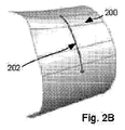
図2Aおよび図2Bには、CADモデル200における測地線202が描かれている。測地線202は、CADモデル200のサーフェスの定義に基づき標準最小距離に従って得られたものである。図2Aの場合、測地線202は2つの点から得られたものである。図2Bの場合、測地線202は、1つの点と1つの方向に沿った所定の距離とから得られたものである。
2A and 2B, a
図3Aおよび図3Bには、CADモデル300における測地円302と、CADモデル310における測地弧312とが描かれている。測地円302は、CADモデル300のサーフェス上の点304に対し1つの共通の測地距離を有する複数の点の集合に従って得られたものである。同様に測地弧312は、CADモデル310のサーフェス上の点314に対し1つの共通の測地距離を有する複数の点の集合に従って得られたものである。
3A and 3B, a
図4には、CADモデル400のサーフェス上の投影曲線402が描かれている。この実施例によれば、曲線網404がCADモデル400のサーフェス上に投影されており、これによって相応の測地投影曲線網402が生成される。
In FIG. 4, a
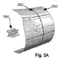
図5Aおよび図5Bには、CADモデルにおける交差曲線が描かれている。図5Aによる実施例の場合、オブジェクト504とCADモデル500との交差によって、測地交差曲線502が生成される。図5Bによる実施例の場合、オブジェクト514とCADモデル510との交差によって、測地交差曲線512が生成される。
5A and 5B depict cross curves in a CAD model. In the embodiment according to FIG. 5A, a
図6には、CADモデル600のサーフェス上の測地オフセット曲線602が描かれている。この実施例によれば、測地オフセット曲線602は、各曲線間の測地オフセット距離がサーフェス全体にわたり一定に維持されるように、CADモデル600のサーフェス上の曲線604からオフセットしている。
In FIG. 6, a geodetic offset
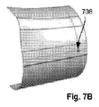
図7Aおよび図7Bには、CADモデルにおける測地点が描かれている。これらの点によって、その生成物である「レシピ」が描かれる。点702は、サーフェス上に位置する1つの点である。点704は、サーフェス上で曲線上に位置する1つの点である。点706は、サーフェス上で2つの曲線の交差点に位置する1つの点である。点708は、サーフェス上に位置し1つの曲線からオフセットしている1つの点である。
In FIG. 7A and FIG. 7B, a station point in the CAD model is drawn. With these points, the product "recipe" is drawn.
図8Aおよび図8Bには、CADモデルにおける測地寸法が描かれている。図8Aの実施例の場合、CADモデル800における点802は、垂直方向の線から測地寸法804だけオフセットしている。この寸法は、上述の点と線との間の測地距離によって測定されたものである。同様に図8Bの実施例の場合、CADモデル810における点812は、水平方向の線から測地寸法814だけオフセットしている。
8A and 8B depict geodetic dimensions in the CAD model. In the example of FIG. 8A, the
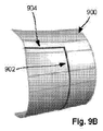
図9Aおよび図9Bには、CADモデルにおけるトリミング測地曲線が描かれている。図9Aには、CADモデル900のサーフェス上で交差する測地曲線902および904が描かれている。図9Bには、これらの測地曲線が交差部分でトリミングされた後の状態が描かれている。
9A and 9B show trimming geodesic curves in the CAD model. FIG. 9A depicts
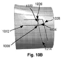
図10A〜図10Dには、測地フィレットおよび測地面取りが描かれており、これについては、あとで図12のフローチャートを参照しながら説明する。図10Aには、CADモデル1000のサーフェス上で交差する曲線1002および1004が描かれている。
FIGS. 10A to 10D depict a geodesic fillet and a geodesic measure, which will be described later with reference to the flowchart of FIG. FIG. 10A depicts
図10Bには、オフセット曲線1012および1014、交差点1008、測地線1022および1024、ならびに終点1026および1028が描かれている。
In FIG. 10B, offset
図10Cには測地フィレット1006が描かれており、更新されたCADモデル1050において、この測地フィレット1006によって交差部分が置き換えられている。この場合、測地フィレット1006の半径は、点1008からの測地距離に従って得られたものである。図10Dには測地面取り1010が描かれており、これによって交差部分が置き換えられている。
In FIG. 10C, a
本発明による実施形態は、かかる測地描画、階層ベースによる更新、測地フィレットおよび測地面取り、測地寸法、ならびに本発明による他のフィーチャを組み込むことができる。 Embodiments in accordance with the present invention can incorporate such geodetic rendering, hierarchy-based updates, geodetic fillets and geodetic measurements, geodetic dimensions, and other features in accordance with the present invention.
種々の実施形態によれば、曲線のオペレーションが元の曲線の定義と関連づけられており、ここで説明している測地描画プロセスによって、元の定義の編集をフィーチャモデリングシステムと同じように実施できるようになる。本発明による測地描画プロセスの1つの利点は、長いフィーチャツリーを扱う負担をユーザに負わせたままにするのではなく、このプロセスによってすべての従属関係が自動的にカプセル化される、ということである。ユーザは、スクリーン上の曲線を選択するだけで描画プロセスを開始すればよく、編集後、関連する曲線が、本発明によるプロセスによって局所的に更新されるようになる。このことは、他の描画プロセスにまさる重要な利点であり、この場合、曲線はそれらがどのように生成されたのかを記憶しないが、すべての曲線は1回の編集で同時に変形される。 According to various embodiments, the operation of the curve is associated with the definition of the original curve, and the geodetic drawing process described here allows the editing of the original definition to be performed in the same way as a feature modeling system. become. One advantage of the geodetic drawing process according to the present invention is that instead of leaving the burden of handling long feature trees to the user, this process automatically encapsulates all dependencies. is there. The user only has to select the curve on the screen to start the drawing process, and after editing, the associated curve will be updated locally by the process according to the invention. This is an important advantage over other drawing processes, where the curves do not remember how they were generated, but all curves are deformed simultaneously in a single edit.
本発明による種々の測地描画プロセスの出力は、完全なフィーチャモデルにおける多数の曲線を含むただ1つのフィーチャである。このフィーチャは、モデルにおける上流のフィーチャからの完全な結合性を有しており、出力曲線を下流のフィーチャによって参照することができる。このことにより、2Dベースの描画プロセスも差別化される。この場合、1回の変換だけで基準面が異なるものとなる可能性があり、したがって変更に応答して、すべての曲線を一度にリジッドに変換させることができる。 The output of the various geodetic drawing processes according to the present invention is a single feature that contains a number of curves in a complete feature model. This feature has full connectivity from upstream features in the model, and the output curve can be referenced by downstream features. This also differentiates the 2D based drawing process. In this case, the reference plane may be different by only one conversion, so all curves can be converted to rigid at once in response to the change.
本発明による実施形態は、湾曲したサーフェスと完全に相互作用する。親サーフェスが更新されると、新たなサーフェスの幾何要素およびそれらの相対関係に基づき、それぞれ異なるようにすべての曲線を更新することができる。本発明による実施形態によって、このような複雑な更新が集合的に管理される。 Embodiments according to the present invention fully interact with curved surfaces. When the parent surface is updated, all curves can be updated differently based on the new surface geometry and their relative relationships. Embodiments according to the present invention collectively manage such complex updates.
いくつかのシステムによれば単に総当たりの更新が行われ、このような更新によれば、曲線の生成タイムスタンプに基づきすべての曲線が再生成されるが、これには重大なパフォーマンスの問題が伴う。このアプローチは、大量のオブジェクトとオペレーション(フィーチャ)が普通に存在し、かつリアルタイムのフィードバックが期待される描画システムにとって、特に許容できない。 Some systems simply do a brute force update, and such an update regenerates all curves based on the curve generation timestamp, which has serious performance issues. Accompany. This approach is particularly unacceptable for a rendering system where a large number of objects and operations (features) are normally present and real-time feedback is expected.
本発明による実施形態は、階層ベースによる更新を用いてこれらの問題に取り組むものである。最初にこのシステムは、各オブジェクトタイプに更新レベルを割り当てる。 Embodiments in accordance with the present invention address these issues using hierarchy-based updates. Initially, the system assigns an update level to each object type.
レベル0は、サーフェス集合(3D CADのボディ)を含むスタティックな入力を参照し、これは第1の方向と第2の方向を含むことができる。それらは測地描画プロセスに対する入力としての役割を果たすことができ、以下で説明する測地描画プロセスよりも先行して存在する基準オブジェクトおよび基準要素である。 Level 0 refers to a static input that includes a surface set (3D CAD body), which can include a first direction and a second direction. They can serve as inputs to the geodetic drawing process and are reference objects and reference elements that exist prior to the geodetic drawing process described below.
レベル1のオブジェクトとは、「アウトサイド・イン」曲線であるステージ1の曲線のことを指す。本明細書において用いられる「アウトサイド・イン」(outside in)とは、測地描画外のオブジェクトの参照により生成される曲線または点のことを指し、「インサイド・イン」(inside in)とは、描画内のオブジェクトの参照により生成される曲線および点のことを指す。たとえば「アウトサイド・イン」測地オフセットとは、(描画のサーフェスの稜線などのように)描画に属さない曲線からのオフセットのことであり、他方、「インサイド・イン」測地オフセットとは、(投影曲線などのように)描画に属する曲線からのオフセットのことである。それらには交差、投影および測地オフセットを含めることができる。レベル1のオブジェクトには、交差点および投影点などのような点も含めることができる。 Level 1 objects refer to stage 1 curves that are “outside-in” curves. As used herein, “outside in” refers to a curve or point generated by reference to an object outside the geodetic drawing, and “inside in” Refers to curves and points generated by reference to objects in the drawing. For example, an “outside-in” geodetic offset is an offset from a curve that does not belong to the drawing (such as the edge of a drawing surface), while an “inside-in” geodetic offset (projection) An offset from a curve that belongs to a drawing (such as a curve). They can include intersections, projections and geodetic offsets. Level 1 objects can also include points such as intersections and projection points.
レベル2のオブジェクトとは、ステージ2の曲線のことを指し、それらの曲線は、「インサイド・イン」曲線を含むステージ1の曲線を参照する曲線である。それらには、測地オフセットを含めることができる。 Level 2 objects refer to stage 2 curves, which are curves that reference stage 1 curves, including “inside-in” curves. They can include geodetic offsets.
レベル3のオブジェクトとは、フェース上および曲線上の測地点および測地寸法のことを指す。それらには、1つの点から1つのフェース上の1つの曲線までの測地距離、1つの終点から1つの曲線に沿った距離、および第1の点から第2の点までの距離を含めることができる。寸法によって測地点のロケーションが制御され、その逆に測地点のロケーションによって寸法が制御される。これらの点および寸法を、同じレベルで同時に解決することができる。 Level 3 objects refer to station and geodetic dimensions on the face and on the curve. They include the geodetic distance from one point to one curve on one face, the distance from one end point to one curve, and the distance from the first point to the second point. it can. The location of the station is controlled by the dimension, and vice versa. These points and dimensions can be solved simultaneously at the same level.
レベル4のオブジェクトとは、線、弧および円を含む測地プリミティブ曲線のことを指す。線または弧を定義する点は、1つの測地点と結合されている。 Level 4 objects refer to geodesic primitive curves including lines, arcs and circles. The points defining a line or arc are combined with one station.
レベル5のオブジェクトとは、フィレットおよび面取りを含む測地コーナー曲線のことを指す。測地コーナー曲線は、低レベルの2つの曲線を参照し、それらの曲線に従ってコーナーが更新されるようになる。しかしながらこれらのコーナー曲線は、次のレベルのトリムオペレーションを単一のフィーチャオブジェクトとして一緒に結合することができる。このトリムは、コーナー曲線の終点において低レベルの曲線に作用する。 Level 5 objects refer to geodetic corner curves including fillets and chamfers. The geodesic corner curve refers to two low-level curves, and the corner is updated according to these curves. However, these corner curves can combine the next level trim operations together as a single feature object. This trim affects the low level curve at the end of the corner curve.
レベル6のオブジェクトは、測地曲線をトリムまたは延長するオペレーションなど、測地曲線範囲のことを指す。システムは、曲線または測地曲線を相互に、またはサーフェス集合の稜線に対し、または外部の基準面に対し、トリムまたは延長することができる。1つの元の曲線において、これを複数回、行わせることができる。システムは毎回、変形される曲線の始点と終点を表す2つの新たな範囲点を定義する。最終的な範囲点だけしか意味がないので、曲線ごとに1つのフィーチャだけしか必要とされず、最終的にそのフィーチャが更新されることになる。 Level 6 objects refer to geodetic curve ranges, such as operations that trim or extend a geodetic curve. The system can trim or extend curves or geodetic curves to each other or to the edges of a set of surfaces, or to an external reference plane. This can be done multiple times in one original curve. Each time the system defines two new range points that represent the start and end points of the curve to be deformed. Since only the final range point is meaningful, only one feature is required per curve, and that feature will eventually be updated.
上述のレベル階層は、一般的な産業上のワークフローに基づいて定義されているが、ワークフローの違いに基づいて変更してもよい。たとえばレベル2の曲線を、本発明の範囲内の種々の実現形態において、レベル4の測地プリミティブ曲線の後に続くものとしてもよい。 The level hierarchy described above is defined based on a general industrial workflow, but may be changed based on a difference in workflow. For example, a level 2 curve may follow a level 4 geodesic primitive curve in various implementations within the scope of the present invention.
高レベルのオブジェクトだけしか、低レベルのオブジェクトを参照できない。これによって、オブジェクトが変更されたときに更新しなければならない従属オブジェクトの個数が大幅に低減され、したがっていっそう高速になる。更新は順位階層に基づき実行され、一般にこの階層を、オブジェクト生成のタイムスタンプの順序とは異ならせることができる。オブジェクトレベルの設計によって、入力が同じであれば、順序づけられた更新結果をタイムスタンプ生成と確実に同じものとすることができる。特に、曲線の修正(コーナー、範囲)は更新の最後に行われるので、元の曲線だけしか参照されず、したがってどのタイムスタンプで曲線が参照されるのかは問題にはならない。さらに各曲線の元の幾何要素の1つのコピーが曲線オブジェクトに保持されるので、元の曲線を再生成することなく曲線変形を高速で更新することができる。元の曲線は、その親オブジェクトが変更されるときだけ更新すればよい。 Only high level objects can reference low level objects. This greatly reduces the number of subordinate objects that must be updated when the object is changed, and is thus much faster. Updates are performed based on a rank hierarchy, and in general this hierarchy can be different from the order of time stamps for object creation. The object level design ensures that the ordered update results are the same as the time stamp generation if the inputs are the same. In particular, since the curve correction (corner, range) is performed at the end of the update, only the original curve is referenced, so it does not matter at which time stamp the curve is referenced. Furthermore, since one copy of the original geometric element of each curve is held in the curve object, the curve deformation can be updated at high speed without regenerating the original curve. The original curve need only be updated when its parent object is changed.
図11には、本発明の実施形態によるプロセスのフローチャートが示されている。このフローチャートはたとえば、ここで説明する1つまたは複数のCADシステム(以下では総称的に「システム」と称する)により実行することができる。 FIG. 11 shows a flowchart of a process according to an embodiment of the present invention. This flowchart may be performed, for example, by one or more CAD systems (hereinafter collectively referred to as “systems”) described herein.
このシステムは、少なくとも1つの三次元(3D)サーフェスを含む1つのCADモデルを受け取る(1105)。3Dサーフェスを、複数の結合されたサーフェスから成る集合により構成することができる。本明細書において用いられる「受け取る」なる表現には、記憶装置からのロード、他のデバイスまたはプロセスからの受け取り、ユーザとの対話を介した受け取り、および他のものを含めることができる。また、3D CADモデルには、上述のレベル0オブジェクトを含めることができる。 The system receives (1105) a CAD model that includes at least one three-dimensional (3D) surface. A 3D surface can be composed of a collection of multiple connected surfaces. As used herein, the expression “receive” may include loads from storage devices, receipts from other devices or processes, receipts through user interaction, and others. In addition, the above-described level 0 object can be included in the 3D CAD model.
システムは、ユーザから第1の測地フィーチャの編集を受け取る(1110)。この編集を、CADモデルへの測地フィーチャの追加、CADモデルからの測地フィーチャの削除、CADモデル内での測地フィーチャの移動、またはCADモデル内の測地フィーチャに対するその他の変更、たとえば寸法、拘束またはその他の点に対する変更、とすることができる。編集が測地フィレットまたは測地面取りの追加の場合には、以下で説明するプロセスを用いることができる。 The system receives a first geodetic feature edit from the user (1110). This can be done by adding geodetic features to the CAD model, deleting geodetic features from the CAD model, moving geodetic features in the CAD model, or other changes to the geodetic features in the CAD model, such as dimensions, constraints or other It is possible to make a change to this point. If the edit is an addition of a geodetic fillet or a geodetic grab, the process described below can be used.
編集に応答して、システムはCADモデルに対し階層ベースによる更新を実施する。その際、第1の測地フィーチャの編集に基づき、CADモデルの少なくとも1つの他のフィーチャに対し相応の編集を実施して、更新されたCADモデルを生成する(1115)。階層ベースによる更新において、第1の測地フィーチャに対する編集に基づき、最低レベルのオブジェクトから最高レベルのオブジェクトまで、CADモデルの他のフィーチャが逐次、更新される。 In response to the edit, the system performs a hierarchy-based update to the CAD model. At this time, based on the editing of the first geodetic feature, corresponding editing is performed on at least one other feature of the CAD model to generate an updated CAD model (1115). In a hierarchy-based update, other features of the CAD model are updated sequentially from the lowest level object to the highest level object based on the edits to the first geodetic feature.
システムは、更新されたCADモデルを記憶する(1120)。 The system stores the updated CAD model (1120).
図12には、本発明の実施形態によるプロセスのフローチャートが示されている。このフローチャートはたとえば、測地フィレットまたは測地面取りを加えるために、ここで説明する1つまたは複数のCADシステム(以下では総称的に「システム」と称する)により実行することができる。以下で説明するプロセスは、上述の図10A〜図10Dに描かれたものである。 FIG. 12 shows a flowchart of a process according to an embodiment of the present invention. This flowchart can be executed, for example, by one or more CAD systems described herein (hereinafter collectively referred to as “systems”) to add geodetic fillets or geodetic measurements. The process described below is depicted in FIGS. 10A-10D above.
このシステムは、少なくとも1つの三次元(3D)サーフェスと、この3Dサーフェス上の2つの側縁曲線とを含む1つのCADモデルを受け取る(1205)。3Dサーフェスを、複数の結合されたサーフェスから成る集合により構成することができる。このステップを、2つの側縁曲線が存在する上述のステップ1105と同じものとすることができる。一般に、これらの側縁曲線を互いに交差したものとすることができ、それらによってフィレットの四分円を定義することができる。
The system receives a CAD model that includes at least one three-dimensional (3D) surface and two edge curves on the 3D surface (1205). A 3D surface can be composed of a collection of multiple connected surfaces. This step can be the same as
システムは、ユーザから第1の測地フィーチャの編集を受け取る(1210)。このステップを上述のステップ1110と同じものとすることができ、この場合、編集は、2つの側縁曲線間における測地フィレットまたは測地面取りの追加である。受け取った編集には、フィレットまたは面取りの半径が含まれる。
The system receives an edit of the first geodetic feature from the user (1210). This step can be the same as
システムは2つの側縁曲線に応じて、それらの側縁曲線の法線方向に沿ってそれぞれ半径と等しい測地距離でオフセット曲線を計算し、オフセット曲線の交差点を求める(1215)。 In response to the two side edge curves, the system calculates an offset curve at geodesic distances equal to the radius along the normal direction of the side edge curves to determine the intersection of the offset curves (1215).
システムはこの交差点から、2つのオフセット線の法線に沿って2つの側縁曲線に戻るフィレット半径とそれぞれ等しい測地距離で、2つの測地線を生成する(1220)。したがってこれら2つの測地線は、個々の終点で2つの側縁曲線と交差することになる。2つの終点は、フィレットまたは面取りのために2つの側縁曲線をトリミングするポジションである。 From this intersection, the system generates (1220) two geodesic curves with geodesic distances equal to the fillet radii that return to the two edge curves along the normals of the two offset lines. Thus, these two geodesic lines will intersect the two side edge curves at their respective end points. The two end points are the positions where the two side edge curves are trimmed for fillet or chamfering.
システムはこれらの終点で、2つの側縁曲線をトリムする(1225)。 At these endpoints, the system trims the two side edge curves (1225).
システムは各終点間において、CADモデルに第1の測地フィーチャを付加する(1230)。 The system adds a first geodetic feature to the CAD model between each endpoint (1230).
第1の測地フィーチャが測地フィレットであれば、システムは、中心として交差点を有する測地弧と、リミットとして2つの終点と、半径としてフィレット半径を生成する。この場合、測地弧は、2つの側縁曲線に対し正接状態となる。したがってこのプロセスによれば、測地正円をコストをかけて生成し、側縁曲線との交差を計算することなく、側縁曲線上の終点を決定することができ、これによってパフォーマンス上の重要な利点が得られる。 If the first geodetic feature is a geodetic fillet, the system generates a geodetic arc with an intersection as the center, two endpoints as limits, and a fillet radius as radius. In this case, the geodesic arc is tangent to the two side edge curves. Therefore, this process can generate a geodesic circle at cost and determine the end point on the side curve without calculating the intersection with the side curve, which is important for performance. Benefits are gained.
第1の測地フィーチャが測地面取りであるならば、システムは、2つの終点間に1つの測地線を追加することによって、測地面取りを生成する。 If the first geodetic feature is a geodesic, the system generates a geodesic by adding a geodesic line between the two endpoints.
その後、このシステムは、たとえば上述のステップ1115〜1120で説明したようにして、CADモデルの更新を実施することができる(1235)。
The system can then perform a CAD model update (1235), for example, as described in
種々の実施形態によれば、駆動寸法に対する1つの点およびその逆に湾曲サーフェス上の1つの点を許可するために、測地寸法を処理することもできる。1つのCADモデルのサーフェス上に、1つの点と、結合された複数の曲線から成る集合とがあれば、システムはその点から曲線集合までの測地(最小)距離を求めて、距離の寸法を生成することができる。曲線の点が変化したときに、この寸法を更新することができる。 According to various embodiments, geodetic dimensions can also be processed to allow one point on the drive dimension and vice versa on a curved surface. If there is a point and a set of connected curves on the surface of a CAD model, the system determines the geodesic (minimum) distance from that point to the set of curves and determines the distance dimension. Can be generated. This dimension can be updated when the point of the curve changes.
他方、この寸法自体を編集して新たな値とすることができ、この値によって、曲線集合までの測地距離としてこの新たな値を有する新たなポジションへ、上述の1つの点が駆動されることになる。 On the other hand, this dimension itself can be edited to a new value, which drives the one point mentioned above to a new position with this new value as the geodetic distance to the curve set. become.
当然ながら当業者に自明のとおり、オペレーションシーケンスにより特に指示または要求がなされないかぎり、上述のプロセスにおけるいくつかのステップを省略してもよいし、同時に実施しても逐次に実施してもよく、あるいは異なる順序で実施してもよい。 Of course, as will be apparent to those skilled in the art, some steps in the process described above may be omitted, performed simultaneously or sequentially, unless otherwise indicated or required by the operational sequence. Or you may implement in a different order.
さらに当業者であれば理解できるとおり、簡単かつ明瞭にするため、本発明による使用に適したあらゆるデータ処理システムの構造およびオペレーションを、本明細書においてすべて描いたまたは説明したわけではない。そうではなく、データ処理システムのうち、本発明に特有のところだけを、または本発明の理解に必要なところだけを描いて説明したにすぎない。データ処理システム100の構造およびオペレーションのその他の部分は、この分野で周知の現在行われている様々な実装形態および実施手法の任意のものに適合させることができる。
Furthermore, as will be appreciated by those skilled in the art, for the sake of simplicity and clarity, not all data processing system structures and operations suitable for use with the present invention have been depicted or described herein. Rather, only the portions of the data processing system that are unique to the present invention or that are necessary for an understanding of the present invention have been described. The rest of the structure and operation of the
ここで特に述べておきたいのは、本発明には、完全に機能的なシステムに関連した説明が含まれているけれども、当業者に自明であるとおり、本発明におけるメカニズムの少なくとも一部分は、機械で使用可能な媒体、コンピュータで使用可能な媒体、またはコンピュータで読み取り可能な媒体に記憶された命令として、任意の種類の形態で配布可能なものであること、さらに本発明は、特定のタイプの命令、信号担体または記憶媒体が使用されようとも、そのような配布物を実際に実行するために等しく適用されることである。機械で使用可能/読み取り可能な媒体、またはコンピュータで使用可能/読み取り可能な媒体の例として、以下のものが含まれる:リードオンリーメモリ(ROM)など不揮発性で変更不可能にコーディングされたタイプの媒体、または消去可能であり電気的にプログラミング可能なリードオンリーメモリ(EEPROM)、ならびにユーザが記録可能なタイプの媒体たとえばフロッピーディスク、ハードディスクドライブ、およびコンパクトディスク型リードオンリーメモリ(CD−ROM)、またはディジタル多用途ディスク(DVD)。 It should be particularly noted that although the present invention includes a description relating to a fully functional system, as will be apparent to those skilled in the art, at least a portion of the mechanisms in the present invention are Can be distributed in any kind of form as instructions stored on a computer usable medium, a computer usable medium, or a computer readable medium. Whether instructions, signal carriers or storage media are used, they are equally applicable to actually implement such distributions. Examples of machine-usable / readable media or computer-usable / readable media include the following: Non-volatile, immutable coded type such as read only memory (ROM) Medium, or erasable and electrically programmable read only memory (EEPROM), and user recordable types of media such as floppy disks, hard disk drives, and compact disk type read only memory (CD-ROM), or Digital versatile disc (DVD).
これまで本発明の実施例について詳しく説明してきたが、当業者であれば理解できるように、最も広い形態で開示した本発明の着想および範囲を超えることなく、様々な変更、置き換え、変形ならびに本明細書で開示した改善を行うことができる。 While the embodiments of the present invention have been described in detail so far, those skilled in the art will appreciate that various changes, substitutions, modifications and books can be made without exceeding the concept and scope of the present invention disclosed in its broadest form. The improvements disclosed in the specification can be made.
本願の記載内容のいずれも、何らかの特定の部材、ステップまたは機能が特許請求の範囲に含まれなければならない必須の要素である、という趣旨で読まれるべきではない。本発明の範囲は、特許付与された請求項によってのみ定められるものである。しかも、厳密な語「〜のための手段」の次に分詞が続かないのであれば、これらの請求項のいずれも、米国特許法第112条(f)が適用されることを意図したものではない。 None of the description in this application should be read to the effect that any particular element, step or function is an essential element that must be included in the claims. The scope of the present invention is defined only by the patented claims. Moreover, if the exact word "means for" is not followed by a participle, none of these claims is intended to apply 35 USC 112 (f). Absent.
Claims (20)
・少なくとも1つの三次元(3D)サーフェスを含むCADモデル(1000)を受け取るステップ(1105)と、
・第1の測地フィーチャ(1002)の編集をユーザから受け取るステップ(1110)と、
・前記編集に応答して、前記CADモデルに対し階層ベースによる更新を実施するステップ(1115)であって、前記第1の測地フィーチャに対する編集に基づき、前記CADモデルにおける少なくとも1つの他のフィーチャ(1004)に対し、相応の編集を実施して、更新されたCADモデル(1050)を生成するステップを含むステップ(1115)と、
・前記更新されたCADモデルを記憶するステップ(1120)と
を含む、
CADモデルにおいて測地編集を実施する方法。 A method for performing geodetic editing in a CAD model, the method being performed by at least one data processing system (100), comprising the following steps:
Receiving (1105) a CAD model (1000) comprising at least one three-dimensional (3D) surface;
Receiving (1110) an edit of the first geodetic feature (1002) from the user;
In response to the editing, performing (1115) a hierarchy-based update to the CAD model, based on editing to the first geodetic feature, at least one other feature in the CAD model ( 1004), performing corresponding edits to generate an updated CAD model (1050);
Storing (1120) the updated CAD model;
A method for performing geodetic editing in a CAD model.
請求項1記載の方法。 In the update based on the hierarchy, the curve of the stage 1 (602), the curve of the stage 2 that refers to the curve of the stage 1 (604), the measurement point on the face and the curve (704), the geodetic dimension (804), the geodetic survey Update in order for primitive curves, geodetic corner curves, and geodetic curve ranges,
The method of claim 1.
請求項2記載の方法。 The geodetic corner curve includes at least one of a fillet (1006) and a chamfer (1010).
The method of claim 2.
請求項2記載の方法。 The geodetic curve range includes operations for trimming or extending a geodetic curve (1002, 1004),
The method of claim 2.
請求項2記載の方法。 The geodetic dimension (804) represents the geodetic distance from one point (802) to one curve,
The method of claim 2.
・前記2つの側縁曲線に応じて、該側縁曲線の法線方向に沿ってそれぞれ半径と等しい測地距離で、オフセット曲線(1012,1014)を計算し、該オフセット曲線の交差点(1008)を求め、
・該交差点から、2つのオフセット線の法線方向に沿ってそれぞれ前記2つの側縁曲線に戻る半径と等しい測地距離で、2つの測地線(1022,1024)を生成して、2つの終点(1026,1028)を同定し、
・前記終点の個所で前記2つの側縁曲線をトリムし、
・前記終点の間において、前記CADモデルにフィレット(1006)または面取り(1010)を付加する、
請求項1記載の方法。 The editing of the first geodetic feature from the user is the addition of a fillet or chamfer (1210) between two side curves (1002, 1004) of the CAD model, the system comprising:
In accordance with the two side edge curves, an offset curve (1012 and 1014) is calculated at geodesic distances equal to the radius along the normal direction of the side edge curve, and an intersection (1008) of the offset curves is calculated. Seeking
Generate two geodesic lines (1022, 1024) from the intersection with geodesic distances equal to the radii that return to the two side curve respectively along the normal direction of the two offset lines, and two end points ( 1026, 1028),
Trim the two side edge curves at the end point,
Adding a fillet (1006) or chamfer (1010) to the CAD model between the end points;
The method of claim 1.
前記第1の測地フィーチャが測地面取り(1010)であるならば、前記システムは、2つの終点間に1つの測地線を追加することによって、前記測地面取りを生成する、
請求項6記載の方法。 If the first geodetic feature is a geodetic fillet, the system will have a geodetic arc (1006) with the intersection (1008) as the center, two end points (1026, 1028) as limits, and a fillet radius as radius. Produces
If the first geodetic feature is a geodesic (1010), the system generates the geodesic by adding a geodesic line between two endpoints.
The method of claim 6.
プロセッサ(102)と、アクセス可能なメモリ(108)とが設けられており、該データ処理システムは特に、以下のように構成されている、すなわち、
・少なくとも1つの三次元(3D)サーフェスを含むCADモデル(1000)を受け取り(1105)、
・第1の測地フィーチャ(1002)の編集をユーザから受け取り(1110)、
・前記編集に応答して、前記CADモデルに対し階層ベースによる更新を実施し(1115)、該更新の実施において、前記第1の測地フィーチャに対する編集に基づき、前記CADモデルにおける少なくとも1つの他のフィーチャ(1004)に対し、相応の編集を実施して、更新されたCADモデル(1050)を生成し、
・前記更新されたCADモデルを記憶する(1120)、
ように構成されている、
データ処理システム(100)。 In the data processing system (100),
A processor (102) and an accessible memory (108) are provided, and the data processing system is specifically configured as follows:
Receiving (1105) a CAD model (1000) comprising at least one three-dimensional (3D) surface;
Receiving (1110) an edit of the first geodetic feature (1002) from the user;
In response to the edit, perform a hierarchically-based update to the CAD model (1115), wherein in performing the update, based on the edit to the first geodetic feature, at least one other in the CAD model Appropriate editing is performed on the feature (1004) to generate an updated CAD model (1050),
Storing the updated CAD model (1120);
Configured as
Data processing system (100).
請求項8記載のデータ処理システム。 In the update based on the hierarchy, the curve of the stage 1 (602), the curve of the stage 2 that refers to the curve of the stage 1 (604), the measurement point on the face and the curve (704), the geodetic dimension (804), the geodetic survey Update in order for primitive curves, geodetic corner curves, and geodetic curve ranges,
The data processing system according to claim 8.
請求項9記載のデータ処理システム。 The geodetic corner curve includes at least one of a fillet (1006) and a chamfer (1010).
The data processing system according to claim 9.
請求項9記載のデータ処理システム。 The geodetic curve range includes operations for trimming or extending a geodetic curve (1002, 1004),
The data processing system according to claim 9.
請求項9記載のデータ処理システム。 The geodetic dimension (804) represents the geodetic distance from one point (802) to one curve,
The data processing system according to claim 9.
・前記2つの側縁曲線に応じて、該側縁曲線の法線方向に沿ってそれぞれ半径と等しい測地距離で、オフセット曲線(1012,1014)を計算し、該オフセット曲線の交差点(1008)を求め、
・該交差点から、2つのオフセット線の法線方向に沿ってそれぞれ前記2つの側縁曲線に戻る半径と等しい測地距離で、2つの測地線(1022,1024)を生成して、2つの終点(1026,1028)を同定し、
・前記終点の個所で前記2つの側縁曲線をトリムし、
・前記終点の間において、前記CADモデルにフィレット(1006)または面取り(1010)を付加する、
請求項8記載のデータ処理システム。 The editing of the first geodetic feature from the user is the addition of a fillet or chamfer (1210) between two side curves (1002, 1004) of the CAD model, the system comprising:
In accordance with the two side edge curves, an offset curve (1012 and 1014) is calculated at geodesic distances equal to the radius along the normal direction of the side edge curve, and an intersection (1008) of the offset curves is calculated. Seeking
Generate two geodesic lines (1022, 1024) from the intersection with geodesic distances equal to the radii that return to the two side curve respectively along the normal direction of the two offset lines, and two end points ( 1026, 1028),
Trim the two side edge curves at the end point,
Adding a fillet (1006) or chamfer (1010) to the CAD model between the end points;
The data processing system according to claim 8.
前記第1の測地フィーチャが測地面取り(1010)であるならば、前記システムは、2つの終点間に1つの測地線を追加することによって、前記測地面取りを生成する、
請求項13記載のデータ処理システム。 If the first geodetic feature is a geodetic fillet, the system will have a geodetic arc (1006) with the intersection (1008) as the center, two end points (1026, 1028) as limits, and a fillet radius as radius. Produces
If the first geodetic feature is a geodesic (1010), the system generates the geodesic by adding a geodesic line between two endpoints.
The data processing system according to claim 13.
・少なくとも1つの三次元(3D)サーフェスを含むCADモデル(1000)を受け取り(1105)、
・第1の測地フィーチャ(1002)の編集をユーザから受け取り(1110)、
・前記編集に応答して、前記CADモデルに対し階層ベースによる更新を実施し(1115)、該更新の実施において、前記第1の測地フィーチャに対する編集に基づき、前記CADモデルにおける少なくとも1つの他のフィーチャ(1004)に対し、相応の編集を実施して、更新されたCADモデル(1050)を生成し、
・前記更新されたCADモデルを記憶する(1120)、
非一時的なコンピュータ読み取り可能媒体(126)。 A non-transitory computer readable medium (126) coded with executable instructions that when executed, the one or more data processing systems (100)
Receiving (1105) a CAD model (1000) comprising at least one three-dimensional (3D) surface;
Receiving (1110) an edit of the first geodetic feature (1002) from the user;
In response to the edit, perform a hierarchically-based update to the CAD model (1115), wherein in performing the update, based on the edit to the first geodetic feature, at least one other in the CAD model Appropriate editing is performed on the feature (1004) to generate an updated CAD model (1050),
Storing the updated CAD model (1120);
Non-transitory computer readable medium (126).
請求項15記載のコンピュータ読み取り可能媒体。 In the update based on the hierarchy, the curve of the stage 1 (602), the curve of the stage 2 that refers to the curve of the stage 1 (604), the measurement point on the face and the curve (704), the geodetic dimension (804), the geodetic survey Update in order for primitive curves, geodetic corner curves, and geodetic curve ranges,
The computer readable medium of claim 15.
請求項16記載のコンピュータ読み取り可能媒体。 The geodetic corner curve includes at least one of a fillet (1006) and a chamfer (1010).
The computer readable medium of claim 16.
請求項16記載のコンピュータ読み取り可能媒体。 The geodetic curve range includes operations for trimming or extending a geodetic curve (1002, 1004),
The computer readable medium of claim 16.
請求項16記載のコンピュータ読み取り可能媒体。 The geodetic dimension (804) represents the geodetic distance from one point (802) to one curve,
The computer readable medium of claim 16.
・前記2つの側縁曲線に応じて、該側縁曲線の法線方向に沿ってそれぞれ半径と等しい測地距離で、オフセット曲線(1012,1014)を計算し、該オフセット曲線の交差点(1008)を求め、
・該交差点から、2つのオフセット線の法線方向に沿ってそれぞれ前記2つの側縁曲線に戻る半径と等しい測地距離で、2つの測地線(1022,1024)を生成して、2つの終点(1026,1028)を同定し、
・前記終点の個所で前記2つの側縁曲線をトリムし、
・前記終点の間において、前記CADモデルにフィレット(1006)または面取り(1010)を付加し、
前記第1の測地フィーチャが測地フィレットであるならば、前記システムは、中心として前記交差点(1008)を有する測地弧(1006)と、リミットとして2つの終点(1026,1028)と、半径としてフィレット半径を生成し、
前記第1の測地フィーチャが測地面取り(1010)であるならば、前記システムは、2つの終点間に1つの測地線を追加することによって、前記測地面取りを生成する、
請求項15記載のコンピュータ読み取り可能媒体。 The editing of the first geodetic feature from the user is the addition of a fillet or chamfer (1210) between two side curves (1002, 1004) of the CAD model, the system comprising:
In accordance with the two side edge curves, an offset curve (1012 and 1014) is calculated at geodesic distances equal to the radius along the normal direction of the side edge curve, and an intersection (1008) of the offset curves is calculated. Seeking
Generate two geodesic lines (1022, 1024) from the intersection with geodesic distances equal to the radii that return to the two side curve respectively along the normal direction of the two offset lines, and two end points ( 1026, 1028),
Trim the two side edge curves at the end point,
Between the end points, add fillets (1006) or chamfers (1010) to the CAD model,
If the first geodetic feature is a geodetic fillet, the system will have a geodetic arc (1006) with the intersection (1008) as the center, two end points (1026, 1028) as limits, and a fillet radius as radius. Produces
If the first geodetic feature is a geodesic (1010), the system generates the geodesic by adding a geodesic line between two endpoints.
The computer readable medium of claim 15.
Applications Claiming Priority (1)
| Application Number | Priority Date | Filing Date | Title |
|---|---|---|---|
| PCT/CN2014/077337 WO2015172309A1 (en) | 2014-05-13 | 2014-05-13 | Geodesic sketching on curved surfaces |
Publications (1)
| Publication Number | Publication Date |
|---|---|
| JP2017516227A true JP2017516227A (en) | 2017-06-15 |
Family
ID=54479135
Family Applications (1)
| Application Number | Title | Priority Date | Filing Date |
|---|---|---|---|
| JP2016567564A Ceased JP2017516227A (en) | 2014-05-13 | 2014-05-13 | Geodesic drawing on curved surfaces |
Country Status (5)
| Country | Link |
|---|---|
| US (1) | US20160275206A1 (en) |
| EP (1) | EP3143529A4 (en) |
| JP (1) | JP2017516227A (en) |
| CN (1) | CN106462650A (en) |
| WO (1) | WO2015172309A1 (en) |
Families Citing this family (5)
| Publication number | Priority date | Publication date | Assignee | Title |
|---|---|---|---|---|
| WO2014205632A1 (en) * | 2013-06-24 | 2014-12-31 | Adobe Systems Incorporated | Gravity point drawing method |
| US9957031B2 (en) | 2015-08-31 | 2018-05-01 | The Boeing Company | Systems and methods for manufacturing a tubular structure |
| US9965582B2 (en) * | 2015-08-31 | 2018-05-08 | The Boeing Company | Systems and methods for determining sizes and shapes of geodesic modules |
| CN111325815B (en) * | 2020-03-05 | 2023-05-02 | 成都威爱新经济技术研究院有限公司 | Editing method of multi-level B spline curve |
| CN113409452B (en) * | 2021-07-12 | 2023-01-03 | 深圳大学 | Three-dimensional line generation method, storage medium and system |
Citations (4)
| Publication number | Priority date | Publication date | Assignee | Title |
|---|---|---|---|---|
| JP2006039668A (en) * | 2004-07-22 | 2006-02-09 | Honda Motor Co Ltd | Method and program for calculating fillet surface |
| JP2006048230A (en) * | 2004-08-02 | 2006-02-16 | Toyota Industries Corp | Method for preparing product model in three-dimensional cad system and three-dimensional cad system |
| JP2006209763A (en) * | 2005-01-26 | 2006-08-10 | Solidworks Corp | Recognition and active feature for computer-aided design system |
| JP2011222003A (en) * | 2010-04-02 | 2011-11-04 | Dassault Systemes | Design of part modeled by parallel geodesic curves |
Family Cites Families (8)
| Publication number | Priority date | Publication date | Assignee | Title |
|---|---|---|---|---|
| US6256039B1 (en) * | 1998-08-14 | 2001-07-03 | The Board Of The Leland Stanford Junior University | Methods for manipulating curves constrained to unparameterized surfaces |
| US20070242067A1 (en) * | 2006-04-18 | 2007-10-18 | Buro Happold Limited | SmartForm |
| US7814441B2 (en) * | 2006-05-09 | 2010-10-12 | Inus Technology, Inc. | System and method for identifying original design intents using 3D scan data |
| GB0712552D0 (en) * | 2007-06-29 | 2007-08-08 | Airbus Uk Ltd | Elongate composite structural members and improvements therein |
| CN101807308B (en) * | 2009-02-12 | 2015-07-08 | 富士通株式会社 | Three-dimensional model segmenting device and method |
| EP2521055B1 (en) * | 2011-05-06 | 2019-07-10 | Dassault Systèmes | Selection of three-dimensional parametric shapes |
| US9142042B2 (en) * | 2011-09-13 | 2015-09-22 | University Of Utah Research Foundation | Methods and systems to produce continuous trajectories from discrete anatomical shapes |
| CN104699865B (en) * | 2013-12-09 | 2018-05-22 | 南京智周信息科技有限公司 | A kind of digitalized oral cavity fixes the method and device repaired |
-
2014
- 2014-05-13 EP EP14892106.7A patent/EP3143529A4/en not_active Withdrawn
- 2014-05-13 US US14/435,413 patent/US20160275206A1/en not_active Abandoned
- 2014-05-13 CN CN201480078788.6A patent/CN106462650A/en active Pending
- 2014-05-13 WO PCT/CN2014/077337 patent/WO2015172309A1/en active Application Filing
- 2014-05-13 JP JP2016567564A patent/JP2017516227A/en not_active Ceased
Patent Citations (4)
| Publication number | Priority date | Publication date | Assignee | Title |
|---|---|---|---|---|
| JP2006039668A (en) * | 2004-07-22 | 2006-02-09 | Honda Motor Co Ltd | Method and program for calculating fillet surface |
| JP2006048230A (en) * | 2004-08-02 | 2006-02-16 | Toyota Industries Corp | Method for preparing product model in three-dimensional cad system and three-dimensional cad system |
| JP2006209763A (en) * | 2005-01-26 | 2006-08-10 | Solidworks Corp | Recognition and active feature for computer-aided design system |
| JP2011222003A (en) * | 2010-04-02 | 2011-11-04 | Dassault Systemes | Design of part modeled by parallel geodesic curves |
Also Published As
| Publication number | Publication date |
|---|---|
| US20160275206A1 (en) | 2016-09-22 |
| WO2015172309A1 (en) | 2015-11-19 |
| EP3143529A4 (en) | 2018-01-10 |
| CN106462650A (en) | 2017-02-22 |
| EP3143529A1 (en) | 2017-03-22 |
Similar Documents
| Publication | Publication Date | Title |
|---|---|---|
| US8447576B2 (en) | System and method for producing editable three-dimensional models | |
| JP6324544B2 (en) | Generate relevant 3D product documentation from drawing notes | |
| JP2017516227A (en) | Geodesic drawing on curved surfaces | |
| US20120221297A1 (en) | Global Deformation for a Modeled Object | |
| JP2015525919A (en) | A method for ordering additional constraints in a variational system. | |
| CN103136790A (en) | Creating a surface from a plurality of 3d curves | |
| CN106462654B (en) | Associating material with subject matter in computer-aided design file | |
| US10540454B2 (en) | System maintaining domain-specific 3D models as a graph within computer aided design | |
| JP5837055B2 (en) | System and method for identifying a shape being defined by a single constraint scheme | |
| JP6150805B2 (en) | Data processing apparatus, method executed by data processing apparatus, and non-volatile computer-readable medium in which instructions executable by data processing apparatus are encoded | |
| US20150278400A1 (en) | Hybrid variational solving in cad models | |
| JP6129156B2 (en) | Method of operating CAD data processing system and CAD system | |
| JP6192861B2 (en) | Aerospace industry joggles on multiple adjacent web faces with intersecting runouts | |
| JP5538526B2 (en) | CAD system, method, program and recording medium for wireframe connection | |
| JP6203384B2 (en) | Rule-based constraint interaction in geometric models | |
| JP2013543619A (en) | Integrated non-history and history-based modeling | |
| JP2017519319A (en) | CAD component with overlay data | |
| JP2016524754A (en) | Apparatus and method for defining sketch dimensions in a drawing view | |
| JP2017516229A (en) | Method for building step features in a 3D model | |
| JP5955485B1 (en) | Modeling blends in a solid pocket model | |
| JP6494665B2 (en) | Intelligent constraint selection for positioning tasks | |
| JP6320561B2 (en) | Method and data processing system for product data management | |
| JP6147333B2 (en) | Determining what participates in Boolean domain operations for a conceptual context given an arbitrary body | |
| JP6338696B2 (en) | How to generate and edit large constraint networks |
Legal Events
| Date | Code | Title | Description |
|---|---|---|---|
| A977 | Report on retrieval |
Free format text: JAPANESE INTERMEDIATE CODE: A971007 Effective date: 20171219 |
|
| A131 | Notification of reasons for refusal |
Free format text: JAPANESE INTERMEDIATE CODE: A131 Effective date: 20180109 |
|
| A521 | Request for written amendment filed |
Free format text: JAPANESE INTERMEDIATE CODE: A523 Effective date: 20180409 |
|
| A01 | Written decision to grant a patent or to grant a registration (utility model) |
Free format text: JAPANESE INTERMEDIATE CODE: A01 Effective date: 20181001 |
|
| A045 | Written measure of dismissal of application [lapsed due to lack of payment] |
Free format text: JAPANESE INTERMEDIATE CODE: A045 Effective date: 20190225 |