JP2017513613A - System for closed transfer of fluid - Google Patents
System for closed transfer of fluid Download PDFInfo
- Publication number
- JP2017513613A JP2017513613A JP2016563943A JP2016563943A JP2017513613A JP 2017513613 A JP2017513613 A JP 2017513613A JP 2016563943 A JP2016563943 A JP 2016563943A JP 2016563943 A JP2016563943 A JP 2016563943A JP 2017513613 A JP2017513613 A JP 2017513613A
- Authority
- JP
- Japan
- Prior art keywords
- collet
- syringe adapter
- locking member
- connection interface
- present
- Prior art date
- Legal status (The legal status is an assumption and is not a legal conclusion. Google has not performed a legal analysis and makes no representation as to the accuracy of the status listed.)
- Pending
Links
- 239000012530 fluid Substances 0.000 title claims description 23
- 238000012546 transfer Methods 0.000 title claims description 16
- 230000013011 mating Effects 0.000 claims abstract description 19
- 239000012528 membrane Substances 0.000 claims description 73
- 238000004891 communication Methods 0.000 description 7
- 239000003814 drug Substances 0.000 description 7
- 229940079593 drug Drugs 0.000 description 7
- 238000003466 welding Methods 0.000 description 7
- 239000000314 lubricant Substances 0.000 description 5
- 238000000034 method Methods 0.000 description 5
- 230000008569 process Effects 0.000 description 4
- 230000036541 health Effects 0.000 description 3
- 239000000463 material Substances 0.000 description 3
- 206010028980 Neoplasm Diseases 0.000 description 2
- 201000011510 cancer Diseases 0.000 description 2
- 238000001802 infusion Methods 0.000 description 2
- 239000007788 liquid Substances 0.000 description 2
- 230000007246 mechanism Effects 0.000 description 2
- 238000012986 modification Methods 0.000 description 2
- 230000004048 modification Effects 0.000 description 2
- 238000003825 pressing Methods 0.000 description 2
- 231100000331 toxic Toxicity 0.000 description 2
- 230000002588 toxic effect Effects 0.000 description 2
- 230000007704 transition Effects 0.000 description 2
- 208000012266 Needlestick injury Diseases 0.000 description 1
- 230000006978 adaptation Effects 0.000 description 1
- 239000000853 adhesive Substances 0.000 description 1
- 230000001070 adhesive effect Effects 0.000 description 1
- 238000012387 aerosolization Methods 0.000 description 1
- 239000002246 antineoplastic agent Substances 0.000 description 1
- 230000004888 barrier function Effects 0.000 description 1
- 238000002512 chemotherapy Methods 0.000 description 1
- 229940044683 chemotherapy drug Drugs 0.000 description 1
- 239000011248 coating agent Substances 0.000 description 1
- 238000000576 coating method Methods 0.000 description 1
- 230000006835 compression Effects 0.000 description 1
- 238000007906 compression Methods 0.000 description 1
- 238000002788 crimping Methods 0.000 description 1
- 238000013461 design Methods 0.000 description 1
- 238000011161 development Methods 0.000 description 1
- 230000018109 developmental process Effects 0.000 description 1
- 230000002708 enhancing effect Effects 0.000 description 1
- 201000005787 hematologic cancer Diseases 0.000 description 1
- 208000024200 hematopoietic and lymphoid system neoplasm Diseases 0.000 description 1
- 238000003780 insertion Methods 0.000 description 1
- 230000037431 insertion Effects 0.000 description 1
- 238000005304 joining Methods 0.000 description 1
- 239000010410 layer Substances 0.000 description 1
- 238000005461 lubrication Methods 0.000 description 1
- 210000000653 nervous system Anatomy 0.000 description 1
- 229920001296 polysiloxane Polymers 0.000 description 1
- 239000000843 powder Substances 0.000 description 1
- 230000002265 prevention Effects 0.000 description 1
- 210000004994 reproductive system Anatomy 0.000 description 1
- 230000000717 retained effect Effects 0.000 description 1
- 238000011282 treatment Methods 0.000 description 1
- 230000000007 visual effect Effects 0.000 description 1
Images


Classifications
-
- A—HUMAN NECESSITIES
- A61—MEDICAL OR VETERINARY SCIENCE; HYGIENE
- A61J—CONTAINERS SPECIALLY ADAPTED FOR MEDICAL OR PHARMACEUTICAL PURPOSES; DEVICES OR METHODS SPECIALLY ADAPTED FOR BRINGING PHARMACEUTICAL PRODUCTS INTO PARTICULAR PHYSICAL OR ADMINISTERING FORMS; DEVICES FOR ADMINISTERING FOOD OR MEDICINES ORALLY; BABY COMFORTERS; DEVICES FOR RECEIVING SPITTLE
- A61J1/00—Containers specially adapted for medical or pharmaceutical purposes
- A61J1/14—Details; Accessories therefor
- A61J1/20—Arrangements for transferring or mixing fluids, e.g. from vial to syringe
- A61J1/2003—Accessories used in combination with means for transfer or mixing of fluids, e.g. for activating fluid flow, separating fluids, filtering fluid or venting
- A61J1/2048—Connecting means
-
- A—HUMAN NECESSITIES
- A61—MEDICAL OR VETERINARY SCIENCE; HYGIENE
- A61J—CONTAINERS SPECIALLY ADAPTED FOR MEDICAL OR PHARMACEUTICAL PURPOSES; DEVICES OR METHODS SPECIALLY ADAPTED FOR BRINGING PHARMACEUTICAL PRODUCTS INTO PARTICULAR PHYSICAL OR ADMINISTERING FORMS; DEVICES FOR ADMINISTERING FOOD OR MEDICINES ORALLY; BABY COMFORTERS; DEVICES FOR RECEIVING SPITTLE
- A61J1/00—Containers specially adapted for medical or pharmaceutical purposes
- A61J1/14—Details; Accessories therefor
- A61J1/20—Arrangements for transferring or mixing fluids, e.g. from vial to syringe
- A61J1/2003—Accessories used in combination with means for transfer or mixing of fluids, e.g. for activating fluid flow, separating fluids, filtering fluid or venting
- A61J1/2006—Piercing means
-
- A—HUMAN NECESSITIES
- A61—MEDICAL OR VETERINARY SCIENCE; HYGIENE
- A61J—CONTAINERS SPECIALLY ADAPTED FOR MEDICAL OR PHARMACEUTICAL PURPOSES; DEVICES OR METHODS SPECIALLY ADAPTED FOR BRINGING PHARMACEUTICAL PRODUCTS INTO PARTICULAR PHYSICAL OR ADMINISTERING FORMS; DEVICES FOR ADMINISTERING FOOD OR MEDICINES ORALLY; BABY COMFORTERS; DEVICES FOR RECEIVING SPITTLE
- A61J1/00—Containers specially adapted for medical or pharmaceutical purposes
- A61J1/14—Details; Accessories therefor
- A61J1/20—Arrangements for transferring or mixing fluids, e.g. from vial to syringe
- A61J1/2003—Accessories used in combination with means for transfer or mixing of fluids, e.g. for activating fluid flow, separating fluids, filtering fluid or venting
- A61J1/2048—Connecting means
- A61J1/2055—Connecting means having gripping means
-
- A—HUMAN NECESSITIES
- A61—MEDICAL OR VETERINARY SCIENCE; HYGIENE
- A61J—CONTAINERS SPECIALLY ADAPTED FOR MEDICAL OR PHARMACEUTICAL PURPOSES; DEVICES OR METHODS SPECIALLY ADAPTED FOR BRINGING PHARMACEUTICAL PRODUCTS INTO PARTICULAR PHYSICAL OR ADMINISTERING FORMS; DEVICES FOR ADMINISTERING FOOD OR MEDICINES ORALLY; BABY COMFORTERS; DEVICES FOR RECEIVING SPITTLE
- A61J1/00—Containers specially adapted for medical or pharmaceutical purposes
- A61J1/14—Details; Accessories therefor
- A61J1/20—Arrangements for transferring or mixing fluids, e.g. from vial to syringe
- A61J1/2096—Combination of a vial and a syringe for transferring or mixing their contents
-
- A—HUMAN NECESSITIES
- A61—MEDICAL OR VETERINARY SCIENCE; HYGIENE
- A61J—CONTAINERS SPECIALLY ADAPTED FOR MEDICAL OR PHARMACEUTICAL PURPOSES; DEVICES OR METHODS SPECIALLY ADAPTED FOR BRINGING PHARMACEUTICAL PRODUCTS INTO PARTICULAR PHYSICAL OR ADMINISTERING FORMS; DEVICES FOR ADMINISTERING FOOD OR MEDICINES ORALLY; BABY COMFORTERS; DEVICES FOR RECEIVING SPITTLE
- A61J1/00—Containers specially adapted for medical or pharmaceutical purposes
- A61J1/14—Details; Accessories therefor
- A61J1/1406—Septums, pierceable membranes
-
- A—HUMAN NECESSITIES
- A61—MEDICAL OR VETERINARY SCIENCE; HYGIENE
- A61J—CONTAINERS SPECIALLY ADAPTED FOR MEDICAL OR PHARMACEUTICAL PURPOSES; DEVICES OR METHODS SPECIALLY ADAPTED FOR BRINGING PHARMACEUTICAL PRODUCTS INTO PARTICULAR PHYSICAL OR ADMINISTERING FORMS; DEVICES FOR ADMINISTERING FOOD OR MEDICINES ORALLY; BABY COMFORTERS; DEVICES FOR RECEIVING SPITTLE
- A61J1/00—Containers specially adapted for medical or pharmaceutical purposes
- A61J1/14—Details; Accessories therefor
- A61J1/20—Arrangements for transferring or mixing fluids, e.g. from vial to syringe
- A61J1/2003—Accessories used in combination with means for transfer or mixing of fluids, e.g. for activating fluid flow, separating fluids, filtering fluid or venting
- A61J1/2006—Piercing means
- A61J1/201—Piercing means having one piercing end
-
- A—HUMAN NECESSITIES
- A61—MEDICAL OR VETERINARY SCIENCE; HYGIENE
- A61J—CONTAINERS SPECIALLY ADAPTED FOR MEDICAL OR PHARMACEUTICAL PURPOSES; DEVICES OR METHODS SPECIALLY ADAPTED FOR BRINGING PHARMACEUTICAL PRODUCTS INTO PARTICULAR PHYSICAL OR ADMINISTERING FORMS; DEVICES FOR ADMINISTERING FOOD OR MEDICINES ORALLY; BABY COMFORTERS; DEVICES FOR RECEIVING SPITTLE
- A61J1/00—Containers specially adapted for medical or pharmaceutical purposes
- A61J1/14—Details; Accessories therefor
- A61J1/20—Arrangements for transferring or mixing fluids, e.g. from vial to syringe
- A61J1/2003—Accessories used in combination with means for transfer or mixing of fluids, e.g. for activating fluid flow, separating fluids, filtering fluid or venting
- A61J1/2048—Connecting means
- A61J1/2065—Connecting means having aligning and guiding means
Abstract
シリンジアダプタは、第1端および第2端を有し、第1端が、第1の容器に固定されるように構成されたハウジングと、第1端および第2端を有し、第2端が、ハウジング内に配置されるカニューレと、第1端および第2端を有し、その少なくとも一部がハウジング内に受容されるコレットを含む。コレットは、通路を画定する本体と、通路に受容されるシール部材と、コレットの本体に接続される、弧状で、弾性のロック部材とを含む。コレットは、ロック部材が開かれ、相手コネクタを受容する第1の位置から、ロック部材の径方向外方への移動が規制される第2の位置へ移動可能である。The syringe adapter has a first end and a second end, the first end having a housing configured to be secured to the first container, a first end and a second end, and a second end. Includes a cannula disposed within the housing and a collet having a first end and a second end, at least a portion of which is received within the housing. The collet includes a body defining a passage, a seal member received in the passage, and an arcuate, resilient locking member connected to the body of the collet. The collet is movable from a first position where the locking member is opened and receiving the mating connector to a second position where movement of the locking member radially outward is restricted.
Description
本開示は、一般的には、流体の閉じた移送のためのシステムに関する。特に、本開示は、第1の容器から第2の容器への流体移送中に、漏れのないシールを提供するシステムに関する。 The present disclosure relates generally to a system for closed transfer of fluid. In particular, the present disclosure relates to a system that provides a leak-proof seal during fluid transfer from a first container to a second container.
医療提供者の、癌治療のような有害な薬剤の再構成、移送、および、投与は、医療提供者をこれらの薬剤への曝露の危険にさらし、医療環境に大きな危険を提供し得る。例えば、癌患者を治療する看護師は、化学療法薬およびそれらの毒性作用にさらされることをあえて行う。意図しない化学療法曝露は、神経系に影響を与え、生殖系を損ない、将来的には血液癌を発症するリスクの増大をもたらし得る。毒性薬剤にさらされる医療提供者のリスクを低減するために、これらの薬剤の閉じた移送が重要となる。 The reconfiguration, transport, and administration of harmful drugs such as cancer treatments by health care providers can put the health care providers at risk of exposure to these drugs and can pose a great risk to the health care environment. For example, nurses treating cancer patients dare to be exposed to chemotherapeutic drugs and their toxic effects. Unintentional chemotherapy exposure can affect the nervous system, impair the reproductive system, and increase the risk of developing blood cancer in the future. Closed transport of these drugs is important to reduce the risk of healthcare providers exposed to toxic drugs.
いくつかの薬物は、それらが投与される前に、溶解または希釈されねばならず、それは、針を用いて、一つの容器から、粉末または液体の形態の薬物を包含する密封されたバイアルに溶媒を移送することを伴う。薬物は、バイアルからの針の引き抜き中、および、針がバイアルの内部にある間、バイアルの内部と周囲の大気との間に圧力差が存在するなら、ガス状で、または、エアロゾル化を通して、大気中に不注意に放出され得る。 Some drugs must be dissolved or diluted before they can be administered, using a needle from a container to a sealed vial containing the drug in powder or liquid form. With the transport. The drug is either gaseous or through aerosolization during withdrawal of the needle from the vial and if there is a pressure difference between the inside of the vial and the surrounding atmosphere while the needle is inside the vial. May be inadvertently released into the atmosphere.
一態様において、シリンジアダプタは、第1端が第1の容器に固定されるように構成された、第1端と第2端を有するハウジング、第2端がハウジング内に配置された、第1端と第2端を有するカニューレ、および、コレットの少なくとも一部が、ハウジング内に受容された、第1端と第2端を有するコレットを含む。コレットは、通路を画定する本体、通路に受容されるシール部材、および、コレットの本体に接続された、弧状で、弾性のロック部材を含む。コレットは、ロック部材が、相手コネクタを受容するために開いている、第1の位置から、ロック部材の径方向外方への移動が規制される、第2の位置へ、移動可能である。 In one aspect, the syringe adapter includes a housing having a first end and a second end configured to be secured to the first container at a first end, and a first end disposed within the housing. A cannula having an end and a second end, and at least a portion of the collet includes a collet having a first end and a second end received in the housing. The collet includes a body defining a passage, a seal member received in the passage, and an arcuate, resilient locking member connected to the body of the collet. The collet is movable from a first position where the locking member is open to receive the mating connector to a second position where movement of the locking member radially outward is restricted.
ロック部材は、複数のアームを介して本体に接続され得る。ロック部材は、リング形状であり得、コレットの長手方向軸に垂直な方向に延びる開口部を画定し得る。ロック部材は、ロック部材が、半径方向外方に拡がるのを許可するように構成された、複数の切欠きを有する連続的なリングであり得る。ロック部材は、複数のアームに対して、半径方向内方および半径方向外方に突出し得る。ロック部材は、本体の延長部を介して、本体に接続され得、本体の延長部とロック部材は、ロック部材が、径方向外側に拡がることを許容するように構成されたスリットを画定する。システムは、第1接続インターフェースを有する接続構造を含み得、第1接続インターフェースは、相手コネクタの対応する接続インターフェースと係合するように構成される。コレットは、コレットが第2の位置にあるとき、接続構造の第1接続インターフェースに係合するように構成された、第2接続インターフェースを含み得る。 The lock member can be connected to the main body via a plurality of arms. The locking member may be ring-shaped and may define an opening that extends in a direction perpendicular to the longitudinal axis of the collet. The locking member can be a continuous ring having a plurality of notches configured to allow the locking member to expand radially outward. The locking member may project radially inward and radially outward relative to the plurality of arms. The locking member may be connected to the main body via an extension of the main body, the main body extension and the locking member defining a slit configured to allow the locking member to expand radially outward. The system may include a connection structure having a first connection interface, the first connection interface configured to engage a corresponding connection interface of the mating connector. The collet may include a second connection interface configured to engage the first connection interface of the connection structure when the collet is in the second position.
さらなる態様において、流体の閉じた移送のためのシステムは、第1の容器に固定されるように構成された第1端、および、第2端を有するハウジング、第1端および第2端を有し、第2端がハウジング内に配置されるカニューレ、および、第1端および第2端を有し、コレットの少なくとも一部が、ハウジング内に受容されるコレットを有するシリンジアダプタを含む。コレットは、通路を画定する本体、シール部材、および、本体に接続されたロック部材を含み、コレットは、ロック部材が、相手コネクタを受容するために開いている、第1の位置から、ロック部材の半径方向外方への移動が規制される、第2の位置へ移動可能である。シリンジアダプタは、また、第1接続インターフェースを有する接続構造を含み、第1接続インターフェースは、相手コネクタの対応する接続インターフェースと係合するように構成される。システムは、さらに、メンブレンと、コレットのロック部材を受容し、係合するように構成された、コレットインターフェース表面を有する、第2の構成要素を含む。 In a further aspect, a system for closed transfer of fluid has a first end configured to be secured to a first container and a housing having a second end, a first end and a second end. And a cannula having a second end disposed within the housing and a syringe adapter having a first end and a second end, wherein at least a portion of the collet has a collet received within the housing. The collet includes a body defining a passage, a seal member, and a locking member connected to the body, the collet from the first position where the locking member is open to receive a mating connector from the first position. Can be moved to a second position where movement outward in the radial direction is restricted. The syringe adapter also includes a connection structure having a first connection interface, the first connection interface configured to engage with a corresponding connection interface of the mating connector. The system further includes a membrane and a second component having a collet interface surface configured to receive and engage the collet locking member.
第2の構成要素は、コレットが、第2の位置にあるときに、第1接続インターフェースに係合するように構成された第2接続インターフェースを含み得る。コレットは、コレットが第2の位置にあるときに、接続構造の第1接続インターフェースに係合するように構成された第2接続インターフェースを含み得る。ロック部材は、弧状で、弾性であり得、ロック部材は、複数のアームを介して本体に接続される。ロック部材は、リング形状であり得、コレットの長手方向軸に垂直な方向に延びる開口部を画定する。ロック部材は、ロック部材が、半径方向外方に拡がることを許容するように構成された、複数の切欠きを有する連続的なリングであり得る。ロック部材は、複数のアームに対して、半径方向内方および半径方向外方に突出し得る。ロック部材は、リング形状、弾性であり得、ロック部材は、本体の延長部を介して本体に接続されており、本体の延長部とロック部材は、ロック部材が、半径方向外方に拡がることを許容するように構成されたスリットを画定する。第2の構成要素は、第1端および第2端を有する、患者コネクタであり得、患者コネクタは、通路を画定する本体、および、患者のIVラインに固定されるように構成された患者コネクタの第2端を有する。 The second component may include a second connection interface configured to engage the first connection interface when the collet is in the second position. The collet may include a second connection interface configured to engage the first connection interface of the connection structure when the collet is in the second position. The locking member may be arcuate and elastic, and the locking member is connected to the main body via a plurality of arms. The locking member may be ring-shaped and defines an opening extending in a direction perpendicular to the longitudinal axis of the collet. The locking member can be a continuous ring having a plurality of notches configured to allow the locking member to expand radially outward. The locking member may project radially inward and radially outward relative to the plurality of arms. The lock member may be ring-shaped and elastic, the lock member is connected to the main body via an extension of the main body, and the lock member extends outward in the radial direction. Defining a slit configured to allow The second component may be a patient connector having a first end and a second end, wherein the patient connector is configured to be secured to a body defining a passageway and a patient IV line. Having a second end.
本開示の、上述の、および、その他の、特徴および利点、ならびに、それらを達成する方法は、添付の図面と併せて解される、以下の本開示の態様の説明を参照することによってより明らかになり、本開示自体は、よりよく理解されるであろう。 The foregoing and other features and advantages of the present disclosure, as well as the manner in which they are achieved, will become more apparent by reference to the following description of aspects of the present disclosure, taken in conjunction with the accompanying drawings. Thus, the present disclosure itself will be better understood.
対応する参照文字は、いくつかの図を通して対応する部分を示す。本明細書に述べられた例示は、本開示の例示的な態様を説明し、そのような例示は、いかなる方法においても本開示の範囲を限定するものとして解釈されるべきではない。 Corresponding reference characters indicate corresponding parts throughout the several views. The illustrations set forth herein illustrate exemplary aspects of the disclosure, and such illustrations should not be construed as limiting the scope of the disclosure in any way.
以下の説明は、当業者が、本発明を実施するために企図された、説明された態様を、製造し使用することを可能にするために提供される。しかしながら、種々の修正、均等、変形、および、代替が、当業者には、容易に明らかになるであろう。任意の、および、全ての、そのような修正、変形、均等、および、代替が、本発明の精神および範囲内に入ることが意図される。 The following description is provided to enable any person skilled in the art to make and use the described aspects contemplated for practicing the present invention. However, various modifications, equivalents, variations and alternatives will be readily apparent to those skilled in the art. Any and all such modifications, variations, equivalents, and alternatives are intended to be within the spirit and scope of the present invention.
以下の説明の目的のため、用語「上」「下」、「右」、「左」、「垂直」、「水平」、「頂部」、「底部」、「横方向」、「長手方向」、および、それの派生語は、それが、図面に向いているとして、本発明に関連するであろう。しかし、本発明は、明白にそれに反して特定される場合を除き、様々な代替の変形を想定し得ることが理解されるべきである。また、添付の図面に示され、以下の明細書に記載される、特定の器具は、単に、本発明の例示的な態様であることが理解されるべきである。したがって、本明細書に開示された態様に関連する特定の寸法および他の物理的特性は限定的であると考慮されるべきではない。 For purposes of the following description, the terms “up”, “down”, “right”, “left”, “vertical”, “horizontal”, “top”, “bottom”, “lateral”, “longitudinal”, And its derivatives will be relevant to the present invention as it is suitable for the drawings. However, it is to be understood that the present invention may assume various alternative variations, except where expressly specified to the contrary. It should also be understood that the specific devices illustrated in the accompanying drawings and described in the following specification are merely exemplary aspects of the invention. Thus, specific dimensions and other physical characteristics associated with the embodiments disclosed herein should not be considered limiting.
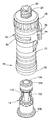
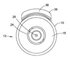
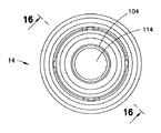
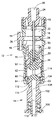
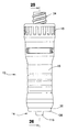
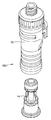
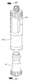
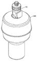
図1を参照すると、流体の閉じた移送のためのシステム10の一態様は、シリンジアダプタ12と患者コネクタ14を含む。システム10は、バイアルのような、第1の容器(図示せず)から、シリンジ、IVバッグ、または、患者IVラインのような、第2の容器(図示せず)への流体の移送中に、漏れのないシールを実質的に提供する。システム10の漏れのないシールは、システム10の使用中、空気と液体の両方の漏れを、実質的に防止する。図示されないが、システム10は、さらに、バイアルアダプタ、圧力均等化装置、または、IVバッグアダプタ、ならびに、注入ラインおよび拡張セットのような、閉鎖系移送器具に典型的に利用される他の構成要素を含み得る。
With reference to FIG. 1, one aspect of a
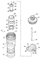
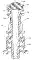
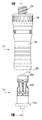
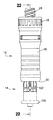
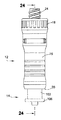
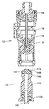
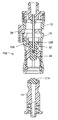
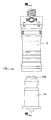
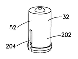
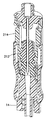
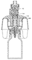
図2−14を参照すると、シリンジアダプタ12の一態様は、第1端18と第2端20を有し、内部空間22を画定するハウジング16を含む。シリンジアダプタ12のハウジング16の第1端18は、通路26を画定する、雌型ルアーコネクタのような、シリンジアタッチメント24を含む。雌ルアーコネクタ(図示せず)が、シリンジの対応する雄ルアーコネクタとの接続のために示されるが、他の適切な接続構造が、シリンジ、容器、または、任意の他の医療器具への接続のために利用され得る。任意の他の適切な接続が利用され得るが、シリンジアタッチメント24は、ねじ接続を介してハウジング16の第1端18に固定される。遠位端30を有するカニューレ28は、シリンジアタッチメント24に固定され、シリンジアタッチメント24の通路26と流体連通する。シリンジアダプタ12は、さらに、シリンジアダプタ12のハウジング16内に配置されたシール構造を含んでいます。シール構造は、第1のメンブレン34を受容するコレット32を含む。コレット32は、以下により詳細に説明されるように、シリンジアダプタ12のハウジング16の内部空間22内を移動するように構成される。シリンジアダプタ12のハウジング16は、使用者によるシリンジアダプタ12の把持を強めるための構造を含み得る。追加または代替の把持構造および表面が、使用者がシリンジアダプタ12の本体を把持することを支援するために提供され得る。
With reference to FIGS. 2-14, one embodiment of the
図2−8を参照すると、シリンジアダプタ12は、シリンジアダプタ12のハウジング16の第1および第2端18、20の中間に配置された、第1接続インターフェース36を含み、それは、シリンジアダプタ12のハウジング16の横方向開口40内に収容されるロック部材38を含む。ロック部材38は、閉位置と開位置との間で移動するように構成される。ロック部材38は、中央開口部42を画定し、シリンジアダプタの使用者またはオペレータの手によって係合されるように構成されたボタン44を含む。ロック部材38は、さらに、シリンジアダプタ12の長手方向に延びる片持ちばね46を含む。ロック部材38は、シリンジアダプタ12のハウジング16から半径方向外方に延びるカム面と係合するように構成される。特に、ロック部材38は、外力がロック部材38に印加されないとき、ロック部材38の中央開口部42に隣接するロック部材38の一部が、シリンジアダプタ12の内部空間22内に配置される、閉位置に配設されるように構成される。ロック部材38の中央開口部42が、シリンジアダプタ12の内部空間22に整合させられるか、内部空間22に挿入されるオブジェクトに対する干渉または障壁を生成しない、開位置に、ロック部材38が移動させられると、片持ちばね46は、カム面に係合し、ロック部材38を閉位置に向かって後方に推進する付勢力を作成する。したがって、ロック部材38が開位置に移動させられると、ロック部材38に作用する外力が解除されたとき、ロック部材38は、閉位置に戻るように推進されるであろう。ロック部材38は、片持ちばね46を有して示されるが、圧縮ばね、拡張ばね、エラストマー材料などを含むが、これらに限定されない、任意の他の適切な付勢部材が設けられ得る。
With reference to FIGS. 2-8, the
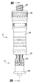
図2を参照すると、ロック部材38は、さらに、ロック部材38から半径方向外方に延びる一対の突起48を含む。一対の突起48は、シリンジアダプタ12のハウジング16に設けられた、対応する突起に係合するように構成され、ロック部材38をシリンジアダプタ12のハウジング16に保持する。つまり、ロック部材38の突起48は、シリンジアダプタ12のハウジング16の突起に係合するように構成され、ロック部材38が、シリンジアダプタ12のハウジング16の横方向開口40から離脱させられ、除去されるのを防止する。
Referring to FIG. 2, the locking
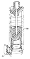
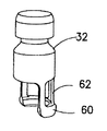
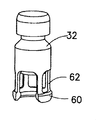
図8−11を参照すると、コレット32は、第1端54と第2端56を有する本体52を有する。本体52は、本体52を通って延びる通路58を画定する。他の適当な形状のコレットが利用され得るが、本体52は、概して円筒形である。コレット32は、さらに、コレット32の本体52に接続されたロック部材60を含む。以下でより詳細に説明されるように、コレット32は、ロック部材60が、開かれ、患者コネクタ14のような、相手コネクタ(図18に示される)を受容する、第1の位置から、ロック部材60の半径方向外方への移動が規制される、第2の位置へ移動可能である。ロック部材60は、複数のアーム62を介して本体52に接続される。ロック部材60は、複数のアーム62を介したロック部材60の本体52への接続の結果として、弧状で弾力性である。より具体的には、複数のアーム62は柔軟であり、ロック部材60が半径方向外方または半径方向内方に延びることを可能にする。一態様において、ロック部材60は、患者コネクタ14のような、相手コネクタが、ロック部材60に挿入されるとき、半径方向外方に延びるように構成され、続いて、コレット32が、第1の位置から第2の位置に移行させられると半径方向内方に移動する。あるいは、患者コネクタ14のような、相手コネクタが、ロック部材60に挿入されるとき、ロック部材60は、半径方向内方または外方に移動しなくてもよく、続いて、コレット32が、第1の位置から第2の位置に移行させられると、半径方向内方に移動し得る。シリンジアダプタ12のハウジング16の第2端20は、コレット32が第1の位置にあるとき、ロック部材60を受け入れる、内部空間22に隣接する環状凹部64を画定する。ハウジング16の環状凹部64は、ロック部材60が半径方向外方に延びるための空間を提供する。コレット32が、第1の位置から第2の位置へ移行させられると、コレット32は、シリンジアダプタ12の第1端18に向かって軸方向に移動し、ロック部材60とシリンジアダプタ12のハウジング16との係合により、ロック部材60は、半径方向内方に付勢される。
With reference to FIGS. 8-11, the
図9に示されるように、コレット32のロック部材60は、コレット32の長手方向軸に垂直な方向に延びる一対の開口部66を画定する。開口部66は、それぞれ、二つのアーム62によってコレット32の本体52に接続された、2つの弧状部分に、ロック部材60を分ける。しかしながら、以下でより詳細に説明されるように、コレット32とロック部材60のための、他の適切な配置および形状が利用され得る。コレット32のロック部材60は、複数のアーム62に対して、半径方向内方および半径方向外方に突出する。
As shown in FIG. 9, the locking
図8−11を再び参照すると、コレット32の本体52は、シリンジアダプタ12の第1接続インターフェース36と係合し、噛み合うように構成された第2接続インターフェース70を含む。第2接続インターフェース70は、コレット32の本体52によって画定され、より具体的には、ロック表面72によって画定される。第2接続インターフェース70は、さらに、コレット32の第1端54によって画定される導入表面を含む。第2接続インターフェース70の導入表面は、コレット32の本体52と導入表面との間の丸みを帯びた移行部を画定する。ロック表面72は、コレット32の本体52に対して窪ませられ、第1接続インターフェース36のロック部材38を受容するように構成された、リング形状の凹部である。他の適切な形状および角度が利用され得るが、ロック表面72は、90度の角度によって画定される。コレット32の第1端54は、第1接続インターフェース36のロック部材38が開位置にあるとき、シリンジアダプタ12の内部空間22内に受容されるように構成され、ロック部材38が閉位置にあるとき、シリンジアダプタ12の内部空間22内において移動することを規制される。第2接続インターフェース70の導入表面は、第1接続インターフェース36のロック部材38に係合するように構成され、ロック部材38を、さらに移動させ、片持ちばね46を、さらに付勢させる。第2接続インターフェース70が、完全に第1接続インターフェース36に係合させられるとき、第1接続インターフェース36のロック部材38は、閉位置にあって、ロック表面72内に受容されるように構成され、第2接続インターフェース70に対する、第1接続インターフェース36の長手方向および横方向移動をロックするが、なお、それに対する回転運動を可能にする。
Referring again to FIGS. 8-11, the
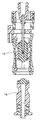
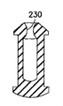
図2および8を参照すると、第1メンブレン34は、第1端84および第2端86を有する本体82を含む。第1メンブレン34の本体82の第1端84と第2端86は、それぞれ、第1ヘッド部88と第2ヘッド部90を含む。第1のメンブレン34の本体82は、本体82の第2端86に向かって第1端84から延びる通路92を画定する。通路92は、本体82の第1および第2端84、86の中間の位置で終端する。図8に示されるように、第1メンブレン34の本体82は、コレット32の通路58によって受容され、コレット32に固定される。第1メンブレン34の第1ヘッド部88は、コレット32の通路58に隣接するコレット32の座繰り部に係合する。第2ヘッド部90は、コレット32の本体52の通路58を越えて延び、第2ヘッド部90は、コレット32の本体52に係合する。以下により詳細に説明されるように、他の適切なメンブレン構造が設けられ得るが、第2ヘッド部90は、凸面を画定する。カニューレ28は、第1メンブレン34の通路92内に受容され、カニューレ28の遠位端30は、コレット32が第1の位置にあるとき、通路92内に配置される。カニューレ28の遠位端30は、コレット32が、第1位置から第2位置に移行させられるとき、第1メンブレン34を貫通し、第1メンブレン34を通って延びるように構成される。第1メンブレン34は、シリンジアダプタ12の使用中に、カニューレ28の中間部分に係合してシールするように構成され、患者コネクタ14または相手部品との、密封された、漏れのない接続を維持する。
With reference to FIGS. 2 and 8, the
以下により詳細に説明されるように、使用中に、患者コネクタ14、バイアルアダプタ、または、IVバッグスパイクからのメンブレンのような、対応するメンブレンによる第1のメンブレン34の係合で、コレット32は、シリンジアダプタ12の第1端18に向かって移動し、第1位置から第2位置へ移行するように構成され、カニューレ28の遠位端30は、第1メンブレン34を貫通し、シリンジアダプタ12を、シリンジアダプタ12に固定された対応するデバイスと流体連通に置く。コレット32が第1の位置に戻されると、第1のメンブレン34は、対応するメンブレンから離脱させられ得、それにより、コレット32と第1メンブレン34の通路58、92内に、カニューレ28の遠位端30を位置づける。そのような配置は、カニューレ28の遠位端30を遮蔽し、針刺し事故を防止し、また、シリンジアダプタ12を使用する場合、流体の移送中に、いかなる流体の漏れをも防止する。
As described in more detail below, during use, the
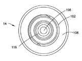
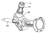
図12−16を参照すると、患者コネクタ14は、第1端104と第2端106を有する本体102を含み、それを通って延びる通路108を画定する。患者コネクタ14の第1端104は、また、コレットインターフェース110を含む。コレットインターフェース110は、患者コネクタ14の本体102の第1端104に対して凹ませられた、患者コネクタ14の本体102の一部によって画定される。患者コネクタ14の本体102の第1端104は、また、第2メンブレン114を受容するメンブレンシート112を含む。シリンジアダプタ12に関連して上述したように、患者コネクタ14の第2メンブレン114は、シリンジアダプタ12の第1メンブレン34と係合し、流体の移送中、シリンジアダプタ12との漏れのない接続を提供するように構成される。任意の他の適切な接続構造が利用され得るが、患者コネクタ14の第2端106は、雄ルアーコネクタのような、IVラインアタッチメント116を含む。
Referring to FIGS. 12-16, the
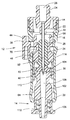
図17−26を参照すると、シリンジアダプタ12を患者コネクタ14に係合する工程が示される。シリンジアダプタ12は、患者コネクタ14に接続されて示されるが、シリンジアダプタ12は、バイアルアダプタおよびIVバッグアダプタを含むが、これらに限定されない、患者のコネクタ14と同様の構造を有する他の構成要素に、同様に接続するであろう。図17および18に示されるように、シリンジアダプタ12の内部空間22は、患者コネクタ14と整列させられる。特に、シリンジアダプタ12の長手方向軸は、閉位置にある第1接続インターフェース36のロック部材38を備えて、患者コネクタ14の長手方向軸と整列させられる。図19および20に示されるように、コレット32が、第1の位置に設けられ、ロック部材60が、患者コネクタ14を受け入れるために開いている状態で、患者コネクタ14は、コレット32に向かってシリンジアダプタ12の内部空間22に移動させられる。
Referring to FIGS. 17-26, the process of engaging the
図21および22を参照すると、シリンジアダプタ12の第1端18に向かう患者コネクタ14のさらなる移動は、第1のメンブレン34が、第2のメンブレン114と係合し、患者コネクタ14の第1端104が、コレット32のロック部材60を通過することをもたらす。上述したように、ロック部材60内の患者コネクタ14の移動は、ロック部材60を、半径方向外方に付勢し得、または、代わりに、ロック部材60のいかなる半径方向の移動もなしに、患者コネクタ14の第1端104を受容し得る。ロック部材60とシリンジアダプタ12のハウジング16の間の干渉、並びに、患者コネクタ14の第1端104とロック部材60との接触に起因して、第1および第2メンブレン34、114が十分に圧縮され、ロック部材60が、患者コネクタ14のコレットインターフェース110内に受容されるまで、コレット32は、シリンジアダプタ12の第1端18に向かって移動しないであろう。第1および第2のメンブレン34、114が十分に圧縮されると、ロック部材60は、ロック部材60のシリンジアダプタ12のハウジング16との係合、および、シリンジアダプタ12の第1端18に向けた、コレット32の継続した軸方向移動に起因して、患者コネクタ14のコレットインターフェース110に押しやられるであろう。
Referring to FIGS. 21 and 22, further movement of the
図23および24を参照すると、シリンジアダプタ12の第1端18に向かう、患者コネクタ14の更なる継続した移動は、コレット32が、また、第1および第2メンブレン34、114の間の係合を介して、シリンジアダプタ12の第1端18に向かって移動することをもたらす。この段階で、コレット32は、第2の位置にあり、患者コネクタ14の第1端104は、コレット32のロック部材60のコレットインターフェース110との係合により、コレット32に、ロックされ、固定されるであろう。コレット32のロック部材60は、コレット32が第1の位置に戻されるまで、患者コネクタ14を解放するために、半径方向外方に拡がることができない。また、この段階での継続した移動中、第1接続インターフェース36のロック部材38は、コレット32の第2接続インターフェース70と係合し、閉位置(図22に示される)から開位置(図24に示される)に、ロック部材38を移行させる。
Referring to FIGS. 23 and 24, further continued movement of the
ロック部材38が閉位置から開位置へ移動させられると、片持ちばね46は、シリンジアダプタ12のハウジング16のカム面に係合し、ロック部材38を閉位置に戻すように付勢する付勢力を生成する。しかしながら、閉位置に戻るそのような移動は、ロック部材38のコレット32の本体52との係合によって防止される。図24は、コレット32と第1接続インターフェース36の間の重なりを示すけれども、本明細書において説明されるように、コレット32は、第1接続インターフェース36を移動させるであろう。同様に、コレット32のロック部材60は、シリンジアダプタ12のハウジング16と重ならないだろうが、本明細書に記載されるように、内方に付勢されるだろう。第1接続インターフェース36のロック部材38が開位置にある状態で、第2接続インターフェース70は、シリンジアダプタ12の内部空間22内におけるその移動を継続させることを可能とされ、患者コネクタ14へのシリンジアダプタ12の係合の工程を続行する。この工程の間、カニューレ28の遠位端30は、第1および第2のメンブレン34、114を穿刺し、患者コネクタ14の通路108と流体連通に置かれる。
When the
図25および26を参照すると、第1のメンブレン34が、シリンジアダプタ12のシリンジアタッチメント24に当接するまで、および/または、患者コネクタ14の第2端106が、シリンジアダプタ12の第2端20に当接するまで、患者コネクタ14とコレット32は、シリンジアダプタ12の第1端18に向かって移動させられる。この段階で、コレット32の第2接続インターフェース70は、第1接続インターフェース36のロック部材38と整列させられ、ロック部材38は、第2接続インターフェース70内に受容される。ロック部材38は、片持ちばね46によって閉位置に向かって付勢され、ロック部材38が、第2接続インターフェース70に到達するとき、ロック部材38は、ロック部材38の一部が、シリンジアダプタ12の内部空間22内に配置される閉位置に、自由に移動する。
Referring to FIGS. 25 and 26, until the
図26に示された位置において、第1接続インターフェース36は、第2接続インターフェース70に対して、完全に、係合され、ロックされる。そのような位置で、シリンジアダプタ12は、第1接続インターフェース36のロック部材38および第2接続インターフェース70の係合により、患者コネクタ14から離脱させられるのを防止される。第1接続インターフェース36および第2接続インターフェース70の間のロック係合は、互いに対する軸方向および横方向の動きを防止するが、第1接続インターフェース36および第2接続インターフェース70は、互いにロックされたとき、互いに対して回転自在であり、これは、有利には、IVラインの絡まり、および/または、構成要素間の回転の欠如に関連する、他の偶発的な離脱または器具の故障を防止する。特に、患者コネクタ14は、典型的には、患者IVラインに取り付けられ、第2接続インターフェース70に対する第1接続インターフェース36の回転は、患者コネクタ14に接続された患者IVラインのねじれを防止することを支援する。しかし、第1接続インターフェース36および第2接続インターフェース70は、所望であれば、そのような相対的な回転を防止するためのキー付き表面構造を備え得る。
In the position shown in FIG. 26, the
図17−26を再び参照すると、第2接続インターフェース70から第1接続インターフェース36を離脱させるために、第1接続インターフェース36のロック部材38のボタン44は、使用者によって捕まれ、半径方向内方に押されて、ロック部材38を、閉位置から開位置に移行させる。患者コネクタ14は、それから、患者コネクタ14にシリンジアダプタ12を接続するための工程の逆の順序で、シリンジアダプタ12の内部空間22から除去され得る。第2接続インターフェース70が、第1接続インターフェース36から分離させられると、ロック部材38は、閉位置に移動させられる。患者コネクタ14は、コレット32が、図22に示される第1の位置に戻されるまで、シリンジアダプタ12から分離され得ず、第1の位置で、コレット32のロック部材60は、ハウジング16の環状凹部64内に、半径方向外方に拡がり得、それによって、コレット32から患者コネクタ14の分離を可能にする。図示されないが、シリンジアダプタ12は、相手部品へのシリンジアダプタの接続中に、使用者への視覚的、触覚的、または、聴覚的指示を提供するために、1つ以上の指示構造を備え得る。
Referring again to FIGS. 17-26, in order to disengage the
上述のシステム10、ならびに、以下に説明されるシステム10の更なる態様は、第1のメンブレン34とカニューレ28との間の摩擦を低減するための1つ以上の構造を含み得る。そのような構造は、第1のメンブレン34および/またはカニューレ28の上または中に設けられた潤滑剤であり得る。潤滑剤は、任意の他の適切な潤滑剤、コーティング、層、材料等が利用され得るが、シリコーン系潤滑剤であり得る。第1のメンブレン34および/またはカニューレ28は、滑りやすい、または、摩擦を低減された材料から製造され得、潤滑剤を塗布され得、および/または、潤滑剤を含浸させられ得る。第1メンブレン34とニードル28との間の摩擦を低減するための構造は、湿式および/または乾式の潤滑システムであり得る。
The
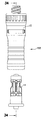
図27−30を参照すると、流体の閉じた移送のための、システム140のさらなる態様が示される。図27−30に示されるシステム140は、図1−26に示され、上述されたシステム10と類似している。しかしながら、図27−30に示されるシステム140において、コレット32のロック部材60は、リング形状であり、コレット32の長手方向軸に対して横方向に延びるただ一つの開口142を画定する。さらに、システム140は、シリンジアダプタ12からシリンジの偶発的離脱を防止する、離脱防止機構144を含む。コレット32が、完全に、シリンジアダプタ12の第1端18に向かって変位させられると、コレット32は、離脱防止機構144と係合し得、シリンジアタッチメント24が自由に回転することを可能にすることで、シリンジアダプタ12からのシリンジの離脱を、実質的に防止する。患者コネクタ14は、また、第2のメンブレン114の対応する形状の部分を受容して係合する、少なくとも一つの突起部と上部リム148を有するメンブレンシート146を含み得る。他の適切な取付け構造が利用され得るが、第2メンブレン114は、超音波溶接を介して、シート146をかしめることにより、または、接着剤によって、メンブレンシート146に固定され得る。
Referring to FIGS. 27-30, a further aspect of the
図31−34を参照すると、流体の閉じた移送のためのシステム152のさらなる態様が示される。図31〜34に示されるシステム152は、図1−26に示され、上述されたシステム10と類似する。図31−34に示されるシステム152において、しかしながら、第1メンブレン154は、コレット32によって画定される対応するシート158内に受容される、フランジ部156を備える概してT字形である。
With reference to FIGS. 31-34, a further aspect of a
図35−38を参照すると、流体の閉じた移送のためのシステム162のさらなる態様が示される。図35〜38に示されるシステム162は、図1−26に示され、上述されたシステムに類似する。しかしながら、図35−38に示されるシステム162において、コレット32は、コレット32内でそれらの間の空間を画定する、一対の離間したメンブレン164を受容する。一対のメンブレン164は、それぞれ、第1および第2のメンブレンシート166に受容される。
With reference to FIGS. 35-38, a further aspect of a
図39−42を参照すると、流体の閉じた移送のためのシステム170のさらなる態様が示される。図39−42に示されるシステム170は、図1−26に示され、上述されたシステム10と類似する。しかしながら、図39−42に示されたシステム170において、第1メンブレン171は、コレット32の対応する突起174によって受容される環状凹部172を画定する。また、第1メンブレン171は、輪郭形成され、コレット32の、対応して輪郭形成された部分によって受容される。第2メンブレン175は、また、患者コネクタ14の対応する突出部178によって受容される環状凹部176を画定する。患者コネクタ14の本体102は、超音波溶接、スピン溶接、または、レーザ溶接のような、任意の適切な固定構造を介して、互いに固定される、外側部分180と内側部分182によって画定される。
Referring to FIGS. 39-42, a further aspect of a
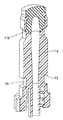
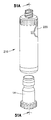
図43A、43B、および44を参照すると、シリンジアダプタ12Aの別の態様が示される。図43A、43B、および44に示されるシリンジアダプタ12Aは、図1−11に示され、上述されたシリンジアダプタ12と類似する。図43A、43B、および44に示されるシリンジアダプタ12Aは、しかしながら、シリンジアダプタ12Aの第2端20またはその近傍に、第1接続インターフェース36を備える。さらに、コレット32に第2接続インターフェース70を備えるよりは、むしろ、患者コネクタ14が、コレットインターフェース110、並びに、第2接続インターフェース70の両方を含む。シリンジアダプタ12Aは、図1−26に関連して上述されたのと同様に作動する。
Referring to FIGS. 43A, 43B, and 44, another aspect of the
図45A−45Fを参照すると、図9−11のコレット32のさらなる態様が示される。図45Aにおいて、コレット32のロック部材60は、連続的でリング形状であり、ロック部材60が半径方向外方に拡がることを可能にするように構成された、複数のノッチを画定する。図45Bにおいて、ロック部材60は、リング形状であり、コレットの長手方向軸に対して横方向に延びる小さなスリットを画定する。図45Cにおいて、コレット32の本体52は、本体52の延長部202を介して、ロック部材60に固定され、ロック部材60は、リング形状であり、ロック部材60が、半径方向外方に拡がることを許容するように構成されたスリット204を画定する。図45Dにおいて、複数のアーム62は、それぞれ、それぞれのアーム62の端の拡大ヘッド部分によって形成される、それぞれのロック部材60を含む。図45Eにおいて、ロック部材60は、半リング形状である。図45Fにおいて、ロック部材60は、弧状であり、単一の開口部を画定する。
45A-45F, a further aspect of the
図46を参照すると、図1−11のシリンジアダプタ12の更なる態様が示される。特に、第1メンブレン34は、概してスリーブ状であり、患者コネクタ14との係合で後退するように構成される。
Referring to FIG. 46, a further aspect of the
図47を参照すると、図1−11のシリンジアダプタ12の更なる態様が示される。特に、第1メンブレン34は、第1のメンブレン34の第1および第2端に凸部を有する、概して円筒形である。
Referring to FIG. 47, a further aspect of the
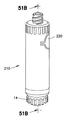
図48A−49Bを参照すると、図1−11のシリンジアダプタ12の更なる態様が示される。図48A−49Bに示されるシリンジアダプタ210は、コレット212と一体的に設けられた、一対の弾性ボタン214を有するコレット212を含む。ボタン214は、シリンジアダプタ210のハウジング16の一対の開口216によって受容され、シリンジアダプタ210が、患者コネクタ14のような相手コネクタと完全に接続され、流体連通すると、コレット212をロックする。ボタン214を押すことは、相手コネクタが、シリンジアダプタ210から離脱させられ、取り外されることを可能にするだろう。
48A-49B, a further aspect of the
図50A−51Bを参照すると、図48A−49Bに示されるように、コレット212にボタン214を設けるよりは、むしろ、間接的なボタン構造が提供され得る。特に、シリンジアダプタ210のハウジング16は、シリンジアダプタ210の内部空間22内に内方に押されるように構成される、一対のボタン220を備える。コレット212は、シリンジアダプタ210が、患者コネクタ14のような相手コネクタと完全に接続され、流体連通すると、コレット212をロックするように構成された、弾性ボタンインターフェース部222を含む。ボタン220を押すことは、コレット212のボタンインターフェース部222を離脱させ、相手コネクタが、シリンジアダプタ210から離脱させられ、取り外されることを可能にするだろう。
Referring to FIGS. 50A-51B, rather than providing a
図52〜54を参照すると、図9−11のコレット32のさらなる態様が示される。特に、一体型、または、単一の成形部品として形成されるコレットを備えるよりも、むしろ、コレット32は、コレット32を形成するために互いに固定される、1つ以上の部品から形成され得る。複数片コレット32態様は、メンブレンが、コレット32の最終的な組立に先立って搭載され得る場合、様々なメンブレン構造を可能にする。コレット32を形成する複数片は、超音波溶接、スピン溶接、または、レーザ溶接のような、任意の適切な接合方法を介して相互に固定され得る。
Referring to FIGS. 52-54, a further embodiment of the
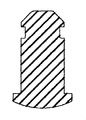
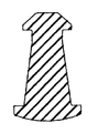
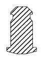
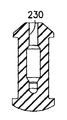
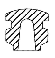
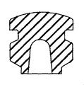
図55A−55Gを参照すると、第1メンブレン34の更なる態様が示される。特に、様々な形状、構造、および、空洞が、第1メンブレン34に利用され得る。また、図55Gに示されるように、第1メンブレン34は、第1のメンブレン34内に配置された挿入片228を含み得る。図55A−55Gに示される形状は、相手部品内に、押し引きされ得、二次組立工程または複数片ハウジングを必要とせずに保持され得る。図55D、55E、および55Fに示される第1メンブレン34の態様は、第1のメンブレン34の頂部にシール部230を含み、使用中に、カニューレ28の中間部に係合して、シールする。
Referring to FIGS. 55A-55G, a further aspect of the
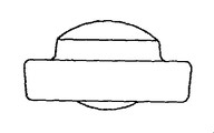
図56A−56Fを参照すると、第2メンブレン114の更なる態様が示される。特に、様々な形状、構造、および、空洞が、第2メンブレン114に利用され得る。
56A-56F, a further aspect of the
図57−60を参照すると、バイアルアダプタ240と係合され、使用される、シリンジアダプタ12が示される。図60に示されるように、バイアルアダプタ240は、患者コネクタ14に、また設けられる、コレットインターフェース110と第2のメンブレン114を含む。シリンジアダプタ12は、シリンジアダプタ12が患者コネクタ14に接続される、上述したのと同様の方法で、バイアルアダプタ240に接続される。バイアルアダプタ240は、バイアルに固定され、コレットインターフェース110を備え、シリンジアダプタ12は、バイアルと流体連通するように配置され得、また、流体が外部環境に漏れるのを防ぐために、圧力均等化装置を備える。
Referring to FIGS. 57-60, the
図61および62を参照すると、IVバッグアダプタ260の一態様が示される。上述したように、シリンジアダプタ12は、典型的には、閉鎖系移送器具システムで利用される、種々の構成要素に接続され得る。IVバッグアダプタ260は、また、患者コネクタ14とバイアルアダプタ240に設けられる、コレットインターフェース110と第2メンブレン114を、また含む。IVバッグアダプタ260は、シリンジアダプタ12が、注入またはIVセットとの流体連通に置かれることを可能にし、第1および第2チャネル264、266を有するスパイク部材262を含む。
With reference to FIGS. 61 and 62, one embodiment of an
本開示は例示的な設計を有するものとして説明されたが、本開示は、本開示の精神および範囲内で、さらに変更され得る。本出願は、したがって、その一般的な原理を用いる、本開示の任意の変形、用途、または、適応をカバーすることを意図される。さらに、本出願は、本開示が関係し、および、添付の特許請求の範囲の範囲内に入る、本開示からの当技術分野で公知または通例の実践内に至るような発展をカバーすることを意図される。 While this disclosure has been described as having an exemplary design, the present disclosure can be further modified within the spirit and scope of this disclosure. This application is therefore intended to cover any variations, uses, or adaptations of the disclosure using its general principles. Furthermore, this application is intended to cover developments that are within the skill of the art known or customary from the present disclosure and that fall within the scope of the appended claims and to which the present disclosure pertains. Intended.
Claims (17)
第1端および第2端を有し、前記第1端が、第1の容器に固定されるように構成される、ハウジングと、
第1端および第2端を有するカニューレであって、該カニューレの第2端が、前記ハウジング内に配置された、前記カニューレと、
第1端および第2端を有するコレットであって、該コレットの少なくとも一部は、前記ハウジング内に受容され、前記コレットは、通路を画定する本体と、前記通路に受容されるシール部材と、弧状で、弾性の、前記コレットの前記本体に接続されるロック部材とを備え、前記コレットは、前記ロック部材が、開かれて、相手コネクタを受容する第1の位置から、前記ロック部材の径方向外方への移動が規制される第2の位置に移動可能である、前記コレット、
を含むことを特徴とするシリンジアダプタ。 A syringe adapter,
A housing having a first end and a second end, wherein the first end is configured to be secured to a first container;
A cannula having a first end and a second end, wherein the cannula second end is disposed within the housing;
A collet having a first end and a second end, wherein at least a portion of the collet is received in the housing, the collet including a body defining a passageway, a seal member received in the passageway, An arcuate, elastic, locking member connected to the body of the collet, the collet having a diameter of the locking member from a first position where the locking member is opened to receive a mating connector The collet movable to a second position in which movement outward in the direction is restricted,
Syringe adapter characterized by including.
シリンジアダプタであって、
第1端および第2端を有し、前記第1端が、第1の容器に固定されるように構成される、ハウジングと、
第1端および第2端を有し、前記第2端が、前記ハウジング内に配置される、カニューレと、
第1端および第2端を有するコレットであって、該コレットの少なくとも一部は、前記ハウジング内に受容され、前記コレットは、通路を画定する本体と、シール部材と、前記本体に接続されたロック部材を含み、前記コレットは、前記ロック部材が開かれ、相手コネクタを受容する第1の位置から、前記ロック部材の半径方向外方への移動が制限される第2の位置へ移動可能である前記コレットと、
第1接続インターフェースを有し、該第1接続インターフェースは、相手コネクタの対応する接続インターフェースと係合するように構成される、接続構造を含む、
シリンジアダプタと、
メンブレンと、前記コレットの前記ロック部材を受容し、前記ロック部材と係合するように構成されたコレットインターフェースを含む第2の構成要素、
を含むことを特徴とする流体の閉じた移送のためのシステム。 A system for closed transfer of fluid, comprising:
A syringe adapter,
A housing having a first end and a second end, wherein the first end is configured to be secured to a first container;
A cannula having a first end and a second end, wherein the second end is disposed within the housing;
A collet having a first end and a second end, wherein at least a portion of the collet is received in the housing, the collet connected to a body defining a passage, a seal member, and the body The collet includes a locking member, and the collet is movable from a first position where the locking member is opened to receive a mating connector to a second position where movement of the locking member radially outward is restricted. A certain collet;
A first connection interface, the first connection interface including a connection structure configured to engage with a corresponding connection interface of the mating connector;
A syringe adapter;
A second component including a membrane and a collet interface configured to receive and engage the locking member of the collet;
A system for closed transfer of fluids.
Applications Claiming Priority (3)
| Application Number | Priority Date | Filing Date | Title |
|---|---|---|---|
| US201461982072P | 2014-04-21 | 2014-04-21 | |
| US61/982,072 | 2014-04-21 | ||
| PCT/US2015/026812 WO2015164333A1 (en) | 2014-04-21 | 2015-04-21 | System for closed transfer of fluids |
Related Child Applications (1)
| Application Number | Title | Priority Date | Filing Date |
|---|---|---|---|
| JP2020012612A Division JP7042856B2 (en) | 2014-04-21 | 2020-01-29 | System for closed transfer of fluid |
Publications (1)
| Publication Number | Publication Date |
|---|---|
| JP2017513613A true JP2017513613A (en) | 2017-06-01 |
Family
ID=53059438
Family Applications (3)
| Application Number | Title | Priority Date | Filing Date |
|---|---|---|---|
| JP2016563943A Pending JP2017513613A (en) | 2014-04-21 | 2015-04-21 | System for closed transfer of fluid |
| JP2020012612A Active JP7042856B2 (en) | 2014-04-21 | 2020-01-29 | System for closed transfer of fluid |
| JP2021162983A Active JP7268109B2 (en) | 2014-04-21 | 2021-10-01 | Systems for closed transfer of fluids |
Family Applications After (2)
| Application Number | Title | Priority Date | Filing Date |
|---|---|---|---|
| JP2020012612A Active JP7042856B2 (en) | 2014-04-21 | 2020-01-29 | System for closed transfer of fluid |
| JP2021162983A Active JP7268109B2 (en) | 2014-04-21 | 2021-10-01 | Systems for closed transfer of fluids |
Country Status (10)
| Country | Link |
|---|---|
| US (2) | US10456329B2 (en) |
| EP (2) | EP4233827A3 (en) |
| JP (3) | JP2017513613A (en) |
| CN (1) | CN106470657B (en) |
| AU (1) | AU2015249915B2 (en) |
| BR (1) | BR112016024684B1 (en) |
| CA (1) | CA2946549C (en) |
| ES (1) | ES2950990T3 (en) |
| IL (1) | IL248410B2 (en) |
| WO (1) | WO2015164333A1 (en) |
Cited By (3)
| Publication number | Priority date | Publication date | Assignee | Title |
|---|---|---|---|---|
| JP2019042054A (en) * | 2017-08-31 | 2019-03-22 | 株式会社トップ | Connector system |
| JP2021514708A (en) * | 2018-02-27 | 2021-06-17 | エクアシールド メディカル リミテッド | Device for fixing device coupling |
| JP7442568B2 (en) | 2018-04-19 | 2024-03-04 | ベクトン ディキンソン アンド カンパニー リミテッド | Syringe adapter with suction assembly |
Families Citing this family (32)
| Publication number | Priority date | Publication date | Assignee | Title |
|---|---|---|---|---|
| US7547300B2 (en) | 2006-04-12 | 2009-06-16 | Icu Medical, Inc. | Vial adaptor for regulating pressure |
| WO2010022095A1 (en) | 2008-08-20 | 2010-02-25 | Icu Medical, Inc. | Anti-reflux vial adaptors |
| CN102724946B (en) | 2009-07-29 | 2015-06-10 | Icu医学有限公司 | Fluid transfer devices and methods of use |
| AU2012296495B2 (en) | 2011-08-18 | 2016-03-10 | Icu Medical, Inc. | Pressure-regulating vial adaptors |
| DK2802377T3 (en) | 2012-01-13 | 2017-03-20 | Icu Medical Inc | Pressure regulating bottle adapter and method |
| AU2013204180B2 (en) | 2012-03-22 | 2016-07-21 | Icu Medical, Inc. | Pressure-regulating vial adaptors |
| US9089475B2 (en) | 2013-01-23 | 2015-07-28 | Icu Medical, Inc. | Pressure-regulating vial adaptors |
| DK2948125T3 (en) | 2013-01-23 | 2019-08-19 | Icu Medical Inc | PRESSURE REGULATING VAPE ADAPTERS |
| AU2014290124B2 (en) | 2013-07-19 | 2019-05-09 | Icu Medical, Inc. | Pressure-regulating fluid transfer systems and methods |
| EP3073982B1 (en) | 2013-11-25 | 2020-04-08 | ICU Medical, Inc. | Methods and system for filling iv bags with therapeutic fluid |
| ES2689083T3 (en) * | 2014-04-21 | 2018-11-08 | Becton Dickinson and Company Limited | Syringe adapter with combined decoupling movement |
| JP6449910B2 (en) | 2014-04-21 | 2019-01-09 | ベクトン ディキンソン アンド カンパニー リミテッド | Fluid transfer device and packaging thereof |
| EP3134053B1 (en) * | 2014-04-21 | 2020-05-27 | Becton Dickinson and Company Limited | System for closed transfer of fluids and membrane arrangements for use thereof |
| US9833605B2 (en) | 2014-04-21 | 2017-12-05 | Becton Dickinson and Company Limited | Fluid transfer device and packaging therefor |
| EP3157491B1 (en) | 2014-06-20 | 2022-06-22 | ICU Medical, Inc. | Pressure-regulating vial adaptors |
| US11883364B2 (en) | 2015-05-22 | 2024-01-30 | Fresenius Kabi Deutschland Gmbh | Connection assembly for directing a medical liquid |
| AU2016266694B2 (en) * | 2015-05-22 | 2020-07-09 | Fresenius Kabi Deutschland Gmbh | Connection assembly for conducting a medical liquid |
| WO2017086867A1 (en) * | 2015-11-19 | 2017-05-26 | Hemcheck Sweden Aktiebolag | A protective device for and method of reducing the risk to medical personnel of accidentally puncturing themselves on a hypodermic needle |
| JP6710758B2 (en) | 2015-12-04 | 2020-06-17 | アイシーユー・メディカル・インコーポレーテッド | Electronic medical fluid transfer device for transferring medical fluid |
| WO2017132588A1 (en) | 2016-01-29 | 2017-08-03 | Icu Medical, Inc. | Pressure-regulating vial adaptors |
| USD851745S1 (en) | 2016-07-19 | 2019-06-18 | Icu Medical, Inc. | Medical fluid transfer system |
| CA3031529A1 (en) | 2016-07-25 | 2018-02-01 | Icu Medical, Inc. | Systems, methods, and components for trapping air bubbles in medical fluid transfer modules and systems |
| AU2017308385B2 (en) * | 2016-08-09 | 2021-12-02 | Nipro Corporation | Connector, Connector-Attached Drug Container, and Liquid Drug Transfer Device |
| CA3037577A1 (en) * | 2016-09-30 | 2018-04-05 | Icu Medical, Inc. | Pressure-regulating vial access devices and methods |
| BR112019014384B1 (en) * | 2017-01-12 | 2023-04-11 | Becton Dickinson and Company Limited | CLOSED SYSTEM STRESS RESISTANT MEMBRANE |
| IL268042B2 (en) * | 2017-01-17 | 2023-04-01 | Becton Dickinson & Co Ltd | Syringe adapter for closed transfer of fluids |
| CA3050460A1 (en) | 2017-01-17 | 2018-07-26 | Becton Dickinson and Company Limited | Syringe adapter |
| CA3050433A1 (en) * | 2017-01-17 | 2018-07-26 | Becton Dickinson and Company Limited | Syringe adapter with cap |
| IL307599A (en) | 2017-01-17 | 2023-12-01 | Becton Dickinson & Co Ltd | Syringe adapter with lock mechanism |
| IL303046B1 (en) * | 2017-01-17 | 2024-02-01 | Becton Dickinson & Co Ltd | Connector for system for closed transfer of fluids |
| US20200282155A1 (en) * | 2017-10-06 | 2020-09-10 | Nordson Corporation | Tamper-evident closure assembly |
| US11590057B2 (en) | 2020-04-03 | 2023-02-28 | Icu Medical, Inc. | Systems, methods, and components for transferring medical fluids |
Citations (3)
| Publication number | Priority date | Publication date | Assignee | Title |
|---|---|---|---|---|
| WO2012002314A1 (en) * | 2010-06-30 | 2012-01-05 | テルモ株式会社 | Connector and connector assembly |
| US8287513B2 (en) * | 2007-09-11 | 2012-10-16 | Carmel Pharma Ab | Piercing member protection device |
| JP2013066748A (en) * | 2007-04-23 | 2013-04-18 | Plastmed Ltd | Method and apparatus for contamination-free transfer of hazardous drug |
Family Cites Families (136)
| Publication number | Priority date | Publication date | Assignee | Title |
|---|---|---|---|---|
| US4436125A (en) | 1982-03-17 | 1984-03-13 | Colder Products Company | Quick connect coupling |
| JPS59127691A (en) | 1983-01-05 | 1984-07-23 | Showa Eng Kk | Advanced treatment of secondary treated water of night soil |
| SE434700B (en) | 1983-05-20 | 1984-08-13 | Bengt Gustavsson | DEVICE FOR AIRED TRANSFER OF SUBSTANCE FROM A KERLE TO ANOTHER |
| CA1215945A (en) | 1983-03-20 | 1986-12-30 | Bengt Gustavsson | Fluid transfer system |
| IT1173370B (en) | 1984-02-24 | 1987-06-24 | Erba Farmitalia | SAFETY DEVICE TO CONNECT A SYRINGE TO THE MOUTH OF A BOTTLE CONTAINING A DRUG OR A TUBE FOR DISPENSING THE SYRINGE DRUG |
| DE3772773D1 (en) | 1986-11-06 | 1991-10-10 | Bengt Gustavsson | CONTAINER FOR STORAGE OR COLLECTION OF LIQUIDS AND DRY SUBSTANCES. |
| US4768568A (en) * | 1987-07-07 | 1988-09-06 | Survival Technology, Inc. | Hazardous material vial apparatus providing expansible sealed and filter vented chambers |
| US5334188A (en) | 1987-12-07 | 1994-08-02 | Nissho Corporation | Connector with injection site |
| US5104158A (en) | 1989-03-13 | 1992-04-14 | Colder Products Company | Two piece molded female coupling |
| US5052725A (en) | 1989-03-13 | 1991-10-01 | Colder Products Company | Two piece molded female coupling |
| US5122129A (en) | 1990-05-09 | 1992-06-16 | Olson Donald J | Sampler coupler device useful in the medical arts |
| DE9105229U1 (en) | 1991-04-27 | 1991-06-13 | B. Braun Melsungen Ag, 3508 Melsungen, De | |
| PT681493E (en) | 1991-12-18 | 2000-12-29 | Icu Medical Inc | MEDICAL VALVE |
| SE9203659L (en) | 1992-12-04 | 1994-02-14 | Dicamed Ab | Valve device for aseptic injection and withdrawal of medical fluid in / out of containers and its use |
| US5332518A (en) | 1992-04-23 | 1994-07-26 | Kao Corporation | Stable slurry-coated sodium percarbonate, process for producing the same and bleach detergent composition containing the same |
| US5478328A (en) | 1992-05-22 | 1995-12-26 | Silverman; David G. | Methods of minimizing disease transmission by used hypodermic needles, and hypodermic needles adapted for carrying out the method |
| GB9211912D0 (en) | 1992-06-04 | 1992-07-15 | Drg Flexpak Ltd | Vial connector system |
| US5290254A (en) | 1992-11-16 | 1994-03-01 | Vaillancourt Vincent L | Shielded cannula assembly |
| US5509911A (en) | 1992-11-27 | 1996-04-23 | Maxxim Medical, Inc. | Rotating adapter for a catheterization system |
| WO1994023775A1 (en) | 1993-03-23 | 1994-10-27 | Abbott Laboratories | Securing collar for cannula connector |
| US5280876A (en) | 1993-03-25 | 1994-01-25 | Roger Atkins | Limited restriction quick disconnect valve |
| US5395348A (en) | 1993-05-04 | 1995-03-07 | Symbiosis Corporation | Medical intravenous administration line connectors |
| US5360011A (en) | 1993-07-13 | 1994-11-01 | Mccallister Teresa D | Blood sample collection |
| US5472430A (en) | 1993-08-18 | 1995-12-05 | Vlv Associates | Protected needle assembly |
| US5609584A (en) | 1994-05-18 | 1997-03-11 | Gettig Technologies, Inc. | Adaptor system for use with a syringe |
| US5487728A (en) | 1994-05-19 | 1996-01-30 | Vaillancourt; Vincent L. | Connector assembly |
| CA2193702C (en) | 1994-06-24 | 2009-10-13 | George A. Lopez | Fluid transfer device and method of use |
| US5545152A (en) | 1994-10-28 | 1996-08-13 | Minimed Inc. | Quick-connect coupling for a medication infusion system |
| US5607392A (en) | 1995-01-13 | 1997-03-04 | Ryder International Corporation | Fixed needle connector for IV assembly and method of assembling |
| US5492147A (en) * | 1995-01-17 | 1996-02-20 | Aeroquip Corporation | Dry break coupling |
| US5647845A (en) | 1995-02-01 | 1997-07-15 | Habley Medical Technology Corporation | Generic intravenous infusion system |
| IL114960A0 (en) | 1995-03-20 | 1995-12-08 | Medimop Medical Projects Ltd | Flow control device |
| SE509950C2 (en) | 1995-05-02 | 1999-03-29 | Carmel Pharma Ab | Device for the administration of toxic liquid |
| US5700248A (en) | 1995-12-15 | 1997-12-23 | Icu Medical, Inc. | Medical valve with tire seal |
| US5807347A (en) | 1995-12-21 | 1998-09-15 | Bonaldo; Jean M. | Medical valve element |
| US5897526A (en) | 1996-06-26 | 1999-04-27 | Vaillancourt; Vincent L. | Closed system medication administering system |
| US6221056B1 (en) | 1996-12-20 | 2001-04-24 | David G. Silverman | Strong diaphragm/safe needle units and components for transfer of fluids |
| US6089541A (en) | 1998-09-10 | 2000-07-18 | Halkey-Roberts Corporation | Valve having a valve body and a deformable stem therein |
| BR9814620A (en) | 1997-11-14 | 2000-10-03 | Kellog Co | Expandable food products and process for manufacturing such products |
| IT236233Y1 (en) | 1997-11-26 | 2000-08-08 | Eurospital S P A | DEVICE FOR THE CONNECTION OF A PHARMACEUTICAL PRODUCT CONTAINER TO A BAG OF LIQUID PRODUCT TO CARRY OUT THE |
| US6159192A (en) | 1997-12-04 | 2000-12-12 | Fowles; Thomas A. | Sliding reconstitution device with seal |
| DE19828651C2 (en) | 1998-06-26 | 2000-07-13 | Fresenius Medical Care De Gmbh | Connector element with closure part for medical technology |
| US6358236B1 (en) | 1998-08-06 | 2002-03-19 | Baxter International Inc. | Device for reconstituting medicaments for injection |
| US6113583A (en) | 1998-09-15 | 2000-09-05 | Baxter International Inc. | Vial connecting device for a sliding reconstitution device for a diluent container |
| AR021220A1 (en) | 1998-09-15 | 2002-07-03 | Baxter Int | CONNECTION DEVICE FOR ESTABLISHING A FLUID COMMUNICATION BETWEEN A FIRST CONTAINER AND A SECOND CONTAINER. |
| US20020173748A1 (en) | 1998-10-29 | 2002-11-21 | Mcconnell Susan | Reservoir connector |
| CA2533850C (en) | 1998-10-29 | 2009-09-01 | Medtronic Minimed, Inc. | Reservoir connector |
| FR2789369B1 (en) | 1999-02-10 | 2001-04-27 | Biodome | CONNECTION DEVICE BETWEEN A CONTAINER AND A CONTAINER AND READY-TO-USE ASSEMBLY COMPRISING SUCH A DEVICE |
| US6832994B2 (en) | 2000-01-24 | 2004-12-21 | Bracco Diagnostics Inc. | Table top drug dispensing vial access adapter |
| US6544246B1 (en) | 2000-01-24 | 2003-04-08 | Bracco Diagnostics, Inc. | Vial access adapter and vial combination |
| US6139534A (en) | 2000-01-24 | 2000-10-31 | Bracco Diagnostics, Inc. | Vial access adapter |
| SE0001278L (en) | 2000-04-06 | 2001-10-08 | Peter Unger Med P U Med Konsul | sterile Coupling |
| JP4372310B2 (en) | 2000-04-10 | 2009-11-25 | ニプロ株式会社 | Adapter for mixed injection |
| US6343629B1 (en) | 2000-06-02 | 2002-02-05 | Carmel Pharma Ab | Coupling device for coupling a vial connector to a drug vial |
| US6629958B1 (en) | 2000-06-07 | 2003-10-07 | Ronald P. Spinello | Leak sealing needle |
| SE517084C2 (en) | 2000-08-10 | 2002-04-09 | Carmel Pharma Ab | Procedures and devices for aseptic preparation |
| FR2819174B1 (en) | 2001-01-08 | 2003-06-13 | Pierre Frezza | BULB FOR PACKAGING AND TRANSFERRING LIQUID OR POWDER FOR MEDICAL USE IN A CONTAINER |
| US6474375B2 (en) | 2001-02-02 | 2002-11-05 | Baxter International Inc. | Reconstitution device and method of use |
| US6656433B2 (en) | 2001-03-07 | 2003-12-02 | Churchill Medical Systems, Inc. | Vial access device for use with various size drug vials |
| US7004934B2 (en) | 2001-09-06 | 2006-02-28 | Vaillancourt Vincent L | Closed system connector assembly |
| US6715520B2 (en) | 2001-10-11 | 2004-04-06 | Carmel Pharma Ab | Method and assembly for fluid transfer |
| JP3972665B2 (en) | 2002-01-25 | 2007-09-05 | 株式会社ジェイ・エム・エス | Aseptic connector system |
| US6911025B2 (en) | 2002-01-25 | 2005-06-28 | Jms Co., Ltd. | Connector system for sterile connection |
| US6875205B2 (en) | 2002-02-08 | 2005-04-05 | Alaris Medical Systems, Inc. | Vial adapter having a needle-free valve for use with vial closures of different sizes |
| US7744581B2 (en) | 2002-04-08 | 2010-06-29 | Carmel Pharma Ab | Device and method for mixing medical fluids |
| US7867215B2 (en) | 2002-04-17 | 2011-01-11 | Carmel Pharma Ab | Method and device for fluid transfer in an infusion system |
| EP2286870B1 (en) | 2002-04-26 | 2014-09-03 | EMD Millipore Corporation | Disposable steam sterilisable medical valve |
| US7350535B2 (en) | 2002-04-26 | 2008-04-01 | Gl Tool And Manufacturing Co. Inc. | Valve |
| SE523001C2 (en) | 2002-07-09 | 2004-03-23 | Carmel Pharma Ab | Coupling component for transmitting medical substances, comprises connecting mechanism for releasable connection to second coupling component having further channel for creating coupling, where connecting mechanism is thread |
| EP1560622B1 (en) | 2002-07-09 | 2008-03-05 | Carmel Pharma AB | A device for injecting medical substances |
| US7040598B2 (en) | 2003-05-14 | 2006-05-09 | Cardinal Health 303, Inc. | Self-sealing male connector |
| US20040249235A1 (en) | 2003-06-03 | 2004-12-09 | Connell Edward G. | Hazardous material handling system and method |
| GB0317175D0 (en) | 2003-07-23 | 2003-08-27 | Liversidge Barry P | Medical needle system |
| KR100940701B1 (en) | 2003-07-31 | 2010-02-08 | 가부시끼가이샤 제이엠에스 | Connector system for medical use |
| US7390321B2 (en) | 2003-09-18 | 2008-06-24 | Advanced Technology Materials, Inc. | Connection having laminar flow for the delivery of a substance |
| EP3108911A1 (en) | 2003-10-30 | 2016-12-28 | Teva Medical Ltd. | Safety drug handling device |
| US20080287914A1 (en) | 2003-12-22 | 2008-11-20 | Philip Wyatt | Medicament administration apparatus |
| US7530546B2 (en) | 2004-01-13 | 2009-05-12 | Rymed Technologies, Inc. | Swabbable needle-free injection port valve system with zero fluid displacement |
| EP1787667A4 (en) | 2004-08-04 | 2010-07-07 | Ajinomoto Kk | Communicating needle used to cause two or more containers to communicate |
| US7731678B2 (en) | 2004-10-13 | 2010-06-08 | Hyprotek, Inc. | Syringe devices and methods for mixing and administering medication |
| US20080045919A1 (en) | 2004-12-23 | 2008-02-21 | Bracco Research S.A. | Liquid Transfer Device for Medical Dispensing Containers |
| JP4647365B2 (en) | 2005-03-31 | 2011-03-09 | 日本シャーウッド株式会社 | Medical connection device |
| US7648491B2 (en) | 2005-05-13 | 2010-01-19 | Bob Rogers | Medical substance transfer system |
| US20070088292A1 (en) | 2005-07-06 | 2007-04-19 | Fangrow Thomas F Jr | Medical connector with closeable male luer |
| EP1951344B1 (en) | 2005-11-07 | 2014-05-28 | Industrie Borla SpA | Vented safe handling vial adapter |
| EP1797919A1 (en) | 2005-12-16 | 2007-06-20 | Bracco Research S.A. | Liquid transfer device for medical dispensing containers |
| AT503142B1 (en) | 2006-01-18 | 2009-05-15 | Friedrich Ing Pipelka | CONTAINER FOR INTRODUCING AT LEAST ONE UNSTERILE VESSEL IN A STERILE AREA |
| US7547300B2 (en) | 2006-04-12 | 2009-06-16 | Icu Medical, Inc. | Vial adaptor for regulating pressure |
| US8257286B2 (en) | 2006-09-21 | 2012-09-04 | Tyco Healthcare Group Lp | Safety connector apparatus |
| US7857805B2 (en) | 2006-10-02 | 2010-12-28 | B. Braun Medical Inc. | Ratcheting luer lock connector |
| US8167863B2 (en) | 2006-10-16 | 2012-05-01 | Carefusion 303, Inc. | Vented vial adapter with filter for aerosol retention |
| AU2007308835A1 (en) | 2006-10-25 | 2008-05-02 | Icu Medical, Inc. | Medical connector |
| US7900659B2 (en) | 2006-12-19 | 2011-03-08 | Carefusion 303, Inc. | Pressure equalizing device for vial access |
| US7883499B2 (en) | 2007-03-09 | 2011-02-08 | Icu Medical, Inc. | Vial adaptors and vials for regulating pressure |
| US7942860B2 (en) | 2007-03-16 | 2011-05-17 | Carmel Pharma Ab | Piercing member protection device |
| US7975733B2 (en) | 2007-05-08 | 2011-07-12 | Carmel Pharma Ab | Fluid transfer device |
| GB2451891A (en) | 2007-08-17 | 2009-02-18 | Univ Sheffield Hallam | Medical fluid connector with features to ensure correct coupling |
| CN101918074B (en) | 2007-09-18 | 2013-02-27 | 麦迪麦珀医疗工程有限公司 | Medicament mixing and injection apparatus |
| PT2231100E (en) | 2008-01-17 | 2012-01-24 | Teva Medical Ltd | Syringe adapter element in drug mixing system |
| US8449521B2 (en) | 2008-02-06 | 2013-05-28 | Intravena, Llc | Methods for making and using a vial shielding convenience kit |
| FR2928539B1 (en) | 2008-03-12 | 2012-02-24 | Vygon | INTERFACING DEVICE FOR PERFORATING BOTTLES FOR THE PREPARATION OF PERFUME FLUIDS |
| WO2009133754A1 (en) | 2008-05-02 | 2009-11-05 | テルモ株式会社 | Connector assembly |
| WO2009133755A1 (en) | 2008-05-02 | 2009-11-05 | テルモ株式会社 | Connector assembly |
| JP4490498B2 (en) | 2008-09-30 | 2010-06-23 | 新田ゼラチン株式会社 | Disease inhibitor |
| US8512309B2 (en) * | 2009-01-15 | 2013-08-20 | Teva Medical Ltd. | Vial adapter element |
| WO2010099000A2 (en) | 2009-02-24 | 2010-09-02 | Teva Medical Ltd. | Vial adapter assembly in drug mixing system |
| US8454579B2 (en) | 2009-03-25 | 2013-06-04 | Icu Medical, Inc. | Medical connector with automatic valves and volume regulator |
| US8317741B2 (en) | 2009-05-26 | 2012-11-27 | Kraushaar Timothy Y | Apparatus and methods for administration of reconstituted medicament |
| CN104721898B (en) | 2009-07-01 | 2018-05-18 | 弗雷塞尼斯医疗保健控股公司 | Drug delivery device and related system and method |
| US8277424B2 (en) | 2009-07-17 | 2012-10-02 | Pan Hsiu-Feng | Needle-less syringe adapter |
| CN102724946B (en) | 2009-07-29 | 2015-06-10 | Icu医学有限公司 | Fluid transfer devices and methods of use |
| EP2480281B1 (en) | 2009-09-04 | 2018-11-07 | B. Braun Melsungen AG | Selectively sealable male needleless connectors |
| US9662271B2 (en) | 2009-10-23 | 2017-05-30 | Amgen Inc. | Vial adapter and system |
| EP2332510B1 (en) | 2009-12-09 | 2013-02-13 | F. Hoffmann-La Roche AG | Connecting element |
| FR2956326A1 (en) | 2010-02-17 | 2011-08-19 | Vygon | CONNECTOR ASSEMBLY FOR A LIQUID CIRCUIT |
| CA2794052C (en) | 2010-03-22 | 2018-10-16 | Alex Yeung | Injection safety system |
| EP2554152A4 (en) | 2010-03-30 | 2015-09-23 | Terumo Corp | Connector and connector assembly |
| NZ629637A (en) | 2010-05-27 | 2015-12-24 | J&J Solutions Inc | Closed fluid transfer system |
| EP2589409A1 (en) | 2010-06-30 | 2013-05-08 | Terumo Kabushiki Kaisha | Connector and connector assembly |
| CN102985050A (en) | 2010-07-12 | 2013-03-20 | 株式会社Jms | Drug solution delivery device for medical use |
| EP2642965B1 (en) | 2010-11-22 | 2015-11-04 | Novartis AG | Adapter |
| EP2462971A1 (en) | 2010-12-13 | 2012-06-13 | Sanofi-Aventis Deutschland GmbH | Needle assembly for drug delivery devices |
| US8857470B2 (en) | 2011-01-25 | 2014-10-14 | Fresenius Kabi Deutschland Gmbh | Connection device for connecting a first reservoir with a second reservoir |
| WO2012117648A1 (en) * | 2011-02-28 | 2012-09-07 | テルモ株式会社 | Connector assembly |
| EP2680807B1 (en) | 2011-03-04 | 2016-08-10 | Duoject Medical Systems Inc. | Easy linking transfer system |
| US20120265163A1 (en) | 2011-04-14 | 2012-10-18 | Marc Bunjiun Cheng | Coupling system to transfer material between containers |
| FR2975896B1 (en) | 2011-06-06 | 2014-06-06 | Biocorp Rech Et Dev | DEVICE FOR CONNECTION BETWEEN A CONTAINER AND A CONTAINER, METHOD FOR ASSEMBLING AND USING SUCH A DEVICE |
| US8793572B2 (en) * | 2011-06-30 | 2014-07-29 | Konica Minolta Laboratory U.S.A., Inc. | Positioning graphical objects within previously formatted text |
| AU2012296495B2 (en) | 2011-08-18 | 2016-03-10 | Icu Medical, Inc. | Pressure-regulating vial adaptors |
| IL215699A0 (en) | 2011-10-11 | 2011-12-29 | Medimop Medical Projects Ltd | Liquid drug reconstitution assemblage for use with iv bag and drug vial |
| EP2773309B1 (en) | 2011-10-31 | 2016-04-20 | GE Healthcare Limited | Pierce and fill device |
| SG192311A1 (en) | 2012-02-02 | 2013-08-30 | Becton Dickinson Holdings Pte Ltd | Adaptor with injection device for coupling to a medical container |
| US9808401B2 (en) | 2012-05-31 | 2017-11-07 | Kinki University | Exposure-preventing cap |
| ES2836824T3 (en) | 2012-06-27 | 2021-06-28 | Carmel Pharma Ab | Medical connection device |
| EP2953858B1 (en) | 2013-02-07 | 2018-04-18 | Equashield Medical Ltd. | Improvements to a closed drug transfer system |
| IL226281A (en) | 2013-05-09 | 2017-01-31 | Kriheli Marino | Needle valve and connectors for use in liquid transfer apparatuses |
-
2015
- 2015-04-21 EP EP23180963.3A patent/EP4233827A3/en active Pending
- 2015-04-21 CN CN201580031197.8A patent/CN106470657B/en active Active
- 2015-04-21 EP EP15721412.3A patent/EP3134056B1/en active Active
- 2015-04-21 JP JP2016563943A patent/JP2017513613A/en active Pending
- 2015-04-21 ES ES15721412T patent/ES2950990T3/en active Active
- 2015-04-21 WO PCT/US2015/026812 patent/WO2015164333A1/en active Application Filing
- 2015-04-21 IL IL248410A patent/IL248410B2/en unknown
- 2015-04-21 BR BR112016024684-5A patent/BR112016024684B1/en active IP Right Grant
- 2015-04-21 US US14/691,831 patent/US10456329B2/en active Active
- 2015-04-21 AU AU2015249915A patent/AU2015249915B2/en active Active
- 2015-04-21 CA CA2946549A patent/CA2946549C/en active Active
-
2019
- 2019-09-23 US US16/578,907 patent/US11903901B2/en active Active
-
2020
- 2020-01-29 JP JP2020012612A patent/JP7042856B2/en active Active
-
2021
- 2021-10-01 JP JP2021162983A patent/JP7268109B2/en active Active
Patent Citations (4)
| Publication number | Priority date | Publication date | Assignee | Title |
|---|---|---|---|---|
| JP2013066748A (en) * | 2007-04-23 | 2013-04-18 | Plastmed Ltd | Method and apparatus for contamination-free transfer of hazardous drug |
| US8287513B2 (en) * | 2007-09-11 | 2012-10-16 | Carmel Pharma Ab | Piercing member protection device |
| WO2012002314A1 (en) * | 2010-06-30 | 2012-01-05 | テルモ株式会社 | Connector and connector assembly |
| US20130076019A1 (en) * | 2010-06-30 | 2013-03-28 | Terumo Kabushiki Kaisha | Connector and connector assembly |
Cited By (4)
| Publication number | Priority date | Publication date | Assignee | Title |
|---|---|---|---|---|
| JP2019042054A (en) * | 2017-08-31 | 2019-03-22 | 株式会社トップ | Connector system |
| JP2021514708A (en) * | 2018-02-27 | 2021-06-17 | エクアシールド メディカル リミテッド | Device for fixing device coupling |
| JP7235758B2 (en) | 2018-02-27 | 2023-03-08 | エクアシールド メディカル リミテッド | Device for fixing device coupling |
| JP7442568B2 (en) | 2018-04-19 | 2024-03-04 | ベクトン ディキンソン アンド カンパニー リミテッド | Syringe adapter with suction assembly |
Also Published As
| Publication number | Publication date |
|---|---|
| IL248410B1 (en) | 2023-07-01 |
| JP2021192885A (en) | 2021-12-23 |
| EP3134056B1 (en) | 2023-07-26 |
| US10456329B2 (en) | 2019-10-29 |
| IL248410A0 (en) | 2016-11-30 |
| EP4233827A2 (en) | 2023-08-30 |
| CA2946549A1 (en) | 2015-10-29 |
| WO2015164333A1 (en) | 2015-10-29 |
| ES2950990T3 (en) | 2023-10-17 |
| CN106470657B (en) | 2020-03-17 |
| EP3134056A1 (en) | 2017-03-01 |
| EP3134056C0 (en) | 2023-07-26 |
| US20150297454A1 (en) | 2015-10-22 |
| JP7042856B2 (en) | 2022-03-28 |
| US20200016036A1 (en) | 2020-01-16 |
| JP7268109B2 (en) | 2023-05-02 |
| JP2020062539A (en) | 2020-04-23 |
| BR112016024684B1 (en) | 2022-06-28 |
| BR112016024684A2 (en) | 2017-08-15 |
| EP4233827A3 (en) | 2023-11-01 |
| CN106470657A (en) | 2017-03-01 |
| CA2946549C (en) | 2019-11-12 |
| US11903901B2 (en) | 2024-02-20 |
| AU2015249915B2 (en) | 2017-11-30 |
| AU2015249915A1 (en) | 2016-11-10 |
| IL248410B2 (en) | 2023-11-01 |
Similar Documents
| Publication | Publication Date | Title |
|---|---|---|
| JP7268109B2 (en) | Systems for closed transfer of fluids | |
| JP6985536B2 (en) | A system for the closed transfer of fluids, and a membrane construct for its use | |
| JP6466967B2 (en) | Syringe adapter with disconnect feedback mechanism |
Legal Events
| Date | Code | Title | Description |
|---|---|---|---|
| A621 | Written request for application examination |
Free format text: JAPANESE INTERMEDIATE CODE: A621 Effective date: 20161215 |
|
| A131 | Notification of reasons for refusal |
Free format text: JAPANESE INTERMEDIATE CODE: A131 Effective date: 20171031 |
|
| A521 | Request for written amendment filed |
Free format text: JAPANESE INTERMEDIATE CODE: A523 Effective date: 20180131 |
|
| A02 | Decision of refusal |
Free format text: JAPANESE INTERMEDIATE CODE: A02 Effective date: 20180515 |
|
| A521 | Request for written amendment filed |
Free format text: JAPANESE INTERMEDIATE CODE: A523 Effective date: 20180918 |
|
| A911 | Transfer to examiner for re-examination before appeal (zenchi) |
Free format text: JAPANESE INTERMEDIATE CODE: A911 Effective date: 20180926 |
|
| A912 | Re-examination (zenchi) completed and case transferred to appeal board |
Free format text: JAPANESE INTERMEDIATE CODE: A912 Effective date: 20181019 |
|
| A521 | Request for written amendment filed |
Free format text: JAPANESE INTERMEDIATE CODE: A523 Effective date: 20200129 |