JP2017512114A - Portable hemodialysis machine and disposable cartridge - Google Patents
Portable hemodialysis machine and disposable cartridge Download PDFInfo
- Publication number
- JP2017512114A JP2017512114A JP2016572355A JP2016572355A JP2017512114A JP 2017512114 A JP2017512114 A JP 2017512114A JP 2016572355 A JP2016572355 A JP 2016572355A JP 2016572355 A JP2016572355 A JP 2016572355A JP 2017512114 A JP2017512114 A JP 2017512114A
- Authority
- JP
- Japan
- Prior art keywords
- dialysate
- pump
- blood
- flow path
- dialyzer
- Prior art date
- Legal status (The legal status is an assumption and is not a legal conclusion. Google has not performed a legal analysis and makes no representation as to the accuracy of the status listed.)
- Pending
Links
- 238000001631 haemodialysis Methods 0.000 title claims abstract description 80
- 230000000322 hemodialysis Effects 0.000 title claims abstract description 80
- 210000004369 blood Anatomy 0.000 claims abstract description 98
- 239000008280 blood Substances 0.000 claims abstract description 98
- 238000000502 dialysis Methods 0.000 claims abstract description 59
- 230000017531 blood circulation Effects 0.000 claims description 38
- 239000012528 membrane Substances 0.000 claims description 21
- 239000000385 dialysis solution Substances 0.000 claims description 13
- 238000011144 upstream manufacturing Methods 0.000 claims description 13
- 238000000108 ultra-filtration Methods 0.000 claims description 9
- 210000003462 vein Anatomy 0.000 claims description 6
- 210000001367 artery Anatomy 0.000 claims description 5
- 230000033001 locomotion Effects 0.000 claims description 5
- 239000002441 uremic toxin Substances 0.000 claims 1
- QGZKDVFQNNGYKY-UHFFFAOYSA-N Ammonia Chemical compound N QGZKDVFQNNGYKY-UHFFFAOYSA-N 0.000 description 42
- 239000012530 fluid Substances 0.000 description 33
- 229910021529 ammonia Inorganic materials 0.000 description 21
- 238000011282 treatment Methods 0.000 description 18
- 239000007788 liquid Substances 0.000 description 16
- 239000000463 material Substances 0.000 description 16
- 238000000034 method Methods 0.000 description 10
- 230000008878 coupling Effects 0.000 description 8
- 238000010168 coupling process Methods 0.000 description 8
- 238000005859 coupling reaction Methods 0.000 description 8
- 230000036772 blood pressure Effects 0.000 description 6
- 239000007789 gas Substances 0.000 description 6
- BVKZGUZCCUSVTD-UHFFFAOYSA-M Bicarbonate Chemical compound OC([O-])=O BVKZGUZCCUSVTD-UHFFFAOYSA-M 0.000 description 5
- 239000012141 concentrate Substances 0.000 description 5
- 238000010586 diagram Methods 0.000 description 5
- 238000012544 monitoring process Methods 0.000 description 5
- 230000002572 peristaltic effect Effects 0.000 description 5
- 239000004033 plastic Substances 0.000 description 5
- CVSVTCORWBXHQV-UHFFFAOYSA-N creatine Chemical compound NC(=[NH2+])N(C)CC([O-])=O CVSVTCORWBXHQV-UHFFFAOYSA-N 0.000 description 4
- 238000009792 diffusion process Methods 0.000 description 4
- 239000004417 polycarbonate Substances 0.000 description 4
- 229920000515 polycarbonate Polymers 0.000 description 4
- 239000000047 product Substances 0.000 description 4
- 230000032258 transport Effects 0.000 description 4
- 239000002699 waste material Substances 0.000 description 4
- XLYOFNOQVPJJNP-UHFFFAOYSA-N water Substances O XLYOFNOQVPJJNP-UHFFFAOYSA-N 0.000 description 4
- XSQUKJJJFZCRTK-UHFFFAOYSA-N Urea Chemical compound NC(N)=O XSQUKJJJFZCRTK-UHFFFAOYSA-N 0.000 description 3
- 239000002253 acid Substances 0.000 description 3
- 230000008901 benefit Effects 0.000 description 3
- 239000004202 carbamide Substances 0.000 description 3
- 230000008859 change Effects 0.000 description 3
- 239000003814 drug Substances 0.000 description 3
- 229940079593 drug Drugs 0.000 description 3
- 230000036541 health Effects 0.000 description 3
- 238000005259 measurement Methods 0.000 description 3
- 230000008569 process Effects 0.000 description 3
- 239000003053 toxin Substances 0.000 description 3
- 231100000765 toxin Toxicity 0.000 description 3
- 108700012359 toxins Proteins 0.000 description 3
- 206010003226 Arteriovenous fistula Diseases 0.000 description 2
- 206010016717 Fistula Diseases 0.000 description 2
- WQZGKKKJIJFFOK-GASJEMHNSA-N Glucose Natural products OC[C@H]1OC(O)[C@H](O)[C@@H](O)[C@@H]1O WQZGKKKJIJFFOK-GASJEMHNSA-N 0.000 description 2
- 239000004696 Poly ether ether ketone Substances 0.000 description 2
- ZLMJMSJWJFRBEC-UHFFFAOYSA-N Potassium Chemical compound [K] ZLMJMSJWJFRBEC-UHFFFAOYSA-N 0.000 description 2
- NIXOWILDQLNWCW-UHFFFAOYSA-N acrylic acid group Chemical group C(C=C)(=O)O NIXOWILDQLNWCW-UHFFFAOYSA-N 0.000 description 2
- 230000009471 action Effects 0.000 description 2
- 238000010276 construction Methods 0.000 description 2
- 229960003624 creatine Drugs 0.000 description 2
- 239000006046 creatine Substances 0.000 description 2
- 230000007423 decrease Effects 0.000 description 2
- 238000007599 discharging Methods 0.000 description 2
- 239000003792 electrolyte Substances 0.000 description 2
- 230000003890 fistula Effects 0.000 description 2
- 239000008103 glucose Substances 0.000 description 2
- 239000012510 hollow fiber Substances 0.000 description 2
- 230000002706 hydrostatic effect Effects 0.000 description 2
- 230000001976 improved effect Effects 0.000 description 2
- 229920002530 polyetherether ketone Polymers 0.000 description 2
- 239000011591 potassium Substances 0.000 description 2
- 229910052700 potassium Inorganic materials 0.000 description 2
- 239000011347 resin Substances 0.000 description 2
- 229920005989 resin Polymers 0.000 description 2
- 239000000126 substance Substances 0.000 description 2
- 238000012546 transfer Methods 0.000 description 2
- OYPRJOBELJOOCE-UHFFFAOYSA-N Calcium Chemical compound [Ca] OYPRJOBELJOOCE-UHFFFAOYSA-N 0.000 description 1
- OKTJSMMVPCPJKN-UHFFFAOYSA-N Carbon Chemical compound [C] OKTJSMMVPCPJKN-UHFFFAOYSA-N 0.000 description 1
- VEXZGXHMUGYJMC-UHFFFAOYSA-M Chloride anion Chemical compound [Cl-] VEXZGXHMUGYJMC-UHFFFAOYSA-M 0.000 description 1
- 206010053567 Coagulopathies Diseases 0.000 description 1
- DGAQECJNVWCQMB-PUAWFVPOSA-M Ilexoside XXIX Chemical compound C[C@@H]1CC[C@@]2(CC[C@@]3(C(=CC[C@H]4[C@]3(CC[C@@H]5[C@@]4(CC[C@@H](C5(C)C)OS(=O)(=O)[O-])C)C)[C@@H]2[C@]1(C)O)C)C(=O)O[C@H]6[C@@H]([C@H]([C@@H]([C@H](O6)CO)O)O)O.[Na+] DGAQECJNVWCQMB-PUAWFVPOSA-M 0.000 description 1
- FYYHWMGAXLPEAU-UHFFFAOYSA-N Magnesium Chemical compound [Mg] FYYHWMGAXLPEAU-UHFFFAOYSA-N 0.000 description 1
- 229910019142 PO4 Inorganic materials 0.000 description 1
- 208000001647 Renal Insufficiency Diseases 0.000 description 1
- 229910006404 SnO 2 Inorganic materials 0.000 description 1
- QCWXUUIWCKQGHC-UHFFFAOYSA-N Zirconium Chemical compound [Zr] QCWXUUIWCKQGHC-UHFFFAOYSA-N 0.000 description 1
- 230000003213 activating effect Effects 0.000 description 1
- 230000004913 activation Effects 0.000 description 1
- 238000013459 approach Methods 0.000 description 1
- 239000002473 artificial blood Substances 0.000 description 1
- WQZGKKKJIJFFOK-VFUOTHLCSA-N beta-D-glucose Chemical compound OC[C@H]1O[C@@H](O)[C@H](O)[C@@H](O)[C@@H]1O WQZGKKKJIJFFOK-VFUOTHLCSA-N 0.000 description 1
- 230000005540 biological transmission Effects 0.000 description 1
- 210000000601 blood cell Anatomy 0.000 description 1
- -1 blood cells Chemical class 0.000 description 1
- 210000004204 blood vessel Anatomy 0.000 description 1
- 239000011575 calcium Substances 0.000 description 1
- 229910052791 calcium Inorganic materials 0.000 description 1
- 229910052799 carbon Inorganic materials 0.000 description 1
- 230000015556 catabolic process Effects 0.000 description 1
- 238000006243 chemical reaction Methods 0.000 description 1
- 230000035602 clotting Effects 0.000 description 1
- 238000011109 contamination Methods 0.000 description 1
- 230000003247 decreasing effect Effects 0.000 description 1
- 230000002950 deficient Effects 0.000 description 1
- 238000006731 degradation reaction Methods 0.000 description 1
- 238000012217 deletion Methods 0.000 description 1
- 230000037430 deletion Effects 0.000 description 1
- 238000013461 design Methods 0.000 description 1
- 238000001514 detection method Methods 0.000 description 1
- 238000010494 dissociation reaction Methods 0.000 description 1
- 230000005593 dissociations Effects 0.000 description 1
- 230000005611 electricity Effects 0.000 description 1
- 239000000835 fiber Substances 0.000 description 1
- 230000006870 function Effects 0.000 description 1
- 238000010438 heat treatment Methods 0.000 description 1
- 230000001939 inductive effect Effects 0.000 description 1
- 239000004615 ingredient Substances 0.000 description 1
- 238000001990 intravenous administration Methods 0.000 description 1
- 210000003734 kidney Anatomy 0.000 description 1
- 201000006370 kidney failure Diseases 0.000 description 1
- 150000002605 large molecules Chemical class 0.000 description 1
- 230000031700 light absorption Effects 0.000 description 1
- 229920002521 macromolecule Polymers 0.000 description 1
- 239000011777 magnesium Substances 0.000 description 1
- 229910052749 magnesium Inorganic materials 0.000 description 1
- 238000007726 management method Methods 0.000 description 1
- 238000004519 manufacturing process Methods 0.000 description 1
- 238000011034 membrane dialysis Methods 0.000 description 1
- 239000000203 mixture Substances 0.000 description 1
- 238000012986 modification Methods 0.000 description 1
- 230000004048 modification Effects 0.000 description 1
- RVTZCBVAJQQJTK-UHFFFAOYSA-N oxygen(2-);zirconium(4+) Chemical compound [O-2].[O-2].[Zr+4] RVTZCBVAJQQJTK-UHFFFAOYSA-N 0.000 description 1
- NBIIXXVUZAFLBC-UHFFFAOYSA-K phosphate Chemical compound [O-]P([O-])([O-])=O NBIIXXVUZAFLBC-UHFFFAOYSA-K 0.000 description 1
- 239000010452 phosphate Substances 0.000 description 1
- 229920001184 polypeptide Polymers 0.000 description 1
- 239000002244 precipitate Substances 0.000 description 1
- 238000003825 pressing Methods 0.000 description 1
- 102000004196 processed proteins & peptides Human genes 0.000 description 1
- 108090000765 processed proteins & peptides Proteins 0.000 description 1
- 238000012545 processing Methods 0.000 description 1
- 108090000623 proteins and genes Proteins 0.000 description 1
- 102000004169 proteins and genes Human genes 0.000 description 1
- 238000004904 shortening Methods 0.000 description 1
- 239000011734 sodium Substances 0.000 description 1
- 229910052708 sodium Inorganic materials 0.000 description 1
- 230000008093 supporting effect Effects 0.000 description 1
- 238000001356 surgical procedure Methods 0.000 description 1
- 238000012360 testing method Methods 0.000 description 1
- 238000012549 training Methods 0.000 description 1
- 229910052726 zirconium Inorganic materials 0.000 description 1
- 229910001928 zirconium oxide Inorganic materials 0.000 description 1
- 229910000166 zirconium phosphate Inorganic materials 0.000 description 1
- LEHFSLREWWMLPU-UHFFFAOYSA-B zirconium(4+);tetraphosphate Chemical compound [Zr+4].[Zr+4].[Zr+4].[O-]P([O-])([O-])=O.[O-]P([O-])([O-])=O.[O-]P([O-])([O-])=O.[O-]P([O-])([O-])=O LEHFSLREWWMLPU-UHFFFAOYSA-B 0.000 description 1
Images


Classifications
-
- A—HUMAN NECESSITIES
- A61—MEDICAL OR VETERINARY SCIENCE; HYGIENE
- A61M—DEVICES FOR INTRODUCING MEDIA INTO, OR ONTO, THE BODY; DEVICES FOR TRANSDUCING BODY MEDIA OR FOR TAKING MEDIA FROM THE BODY; DEVICES FOR PRODUCING OR ENDING SLEEP OR STUPOR
- A61M1/00—Suction or pumping devices for medical purposes; Devices for carrying-off, for treatment of, or for carrying-over, body-liquids; Drainage systems
- A61M1/14—Dialysis systems; Artificial kidneys; Blood oxygenators ; Reciprocating systems for treatment of body fluids, e.g. single needle systems for hemofiltration or pheresis
- A61M1/16—Dialysis systems; Artificial kidneys; Blood oxygenators ; Reciprocating systems for treatment of body fluids, e.g. single needle systems for hemofiltration or pheresis with membranes
- A61M1/1601—Control or regulation
- A61M1/1603—Regulation parameters
-
- A—HUMAN NECESSITIES
- A61—MEDICAL OR VETERINARY SCIENCE; HYGIENE
- A61M—DEVICES FOR INTRODUCING MEDIA INTO, OR ONTO, THE BODY; DEVICES FOR TRANSDUCING BODY MEDIA OR FOR TAKING MEDIA FROM THE BODY; DEVICES FOR PRODUCING OR ENDING SLEEP OR STUPOR
- A61M1/00—Suction or pumping devices for medical purposes; Devices for carrying-off, for treatment of, or for carrying-over, body-liquids; Drainage systems
- A61M1/14—Dialysis systems; Artificial kidneys; Blood oxygenators ; Reciprocating systems for treatment of body fluids, e.g. single needle systems for hemofiltration or pheresis
- A61M1/15—Dialysis systems; Artificial kidneys; Blood oxygenators ; Reciprocating systems for treatment of body fluids, e.g. single needle systems for hemofiltration or pheresis with a cassette forming partially or totally the flow circuit for the treating fluid, e.g. the dialysate fluid circuit or the treating gas circuit
- A61M1/152—Details related to the interface between cassette and machine
- A61M1/1524—Details related to the interface between cassette and machine the interface providing means for actuating on functional elements of the cassette, e.g. plungers
-
- A—HUMAN NECESSITIES
- A61—MEDICAL OR VETERINARY SCIENCE; HYGIENE
- A61M—DEVICES FOR INTRODUCING MEDIA INTO, OR ONTO, THE BODY; DEVICES FOR TRANSDUCING BODY MEDIA OR FOR TAKING MEDIA FROM THE BODY; DEVICES FOR PRODUCING OR ENDING SLEEP OR STUPOR
- A61M1/00—Suction or pumping devices for medical purposes; Devices for carrying-off, for treatment of, or for carrying-over, body-liquids; Drainage systems
- A61M1/14—Dialysis systems; Artificial kidneys; Blood oxygenators ; Reciprocating systems for treatment of body fluids, e.g. single needle systems for hemofiltration or pheresis
- A61M1/15—Dialysis systems; Artificial kidneys; Blood oxygenators ; Reciprocating systems for treatment of body fluids, e.g. single needle systems for hemofiltration or pheresis with a cassette forming partially or totally the flow circuit for the treating fluid, e.g. the dialysate fluid circuit or the treating gas circuit
- A61M1/154—Dialysis systems; Artificial kidneys; Blood oxygenators ; Reciprocating systems for treatment of body fluids, e.g. single needle systems for hemofiltration or pheresis with a cassette forming partially or totally the flow circuit for the treating fluid, e.g. the dialysate fluid circuit or the treating gas circuit with sensing means or components thereof
-
- A—HUMAN NECESSITIES
- A61—MEDICAL OR VETERINARY SCIENCE; HYGIENE
- A61M—DEVICES FOR INTRODUCING MEDIA INTO, OR ONTO, THE BODY; DEVICES FOR TRANSDUCING BODY MEDIA OR FOR TAKING MEDIA FROM THE BODY; DEVICES FOR PRODUCING OR ENDING SLEEP OR STUPOR
- A61M1/00—Suction or pumping devices for medical purposes; Devices for carrying-off, for treatment of, or for carrying-over, body-liquids; Drainage systems
- A61M1/14—Dialysis systems; Artificial kidneys; Blood oxygenators ; Reciprocating systems for treatment of body fluids, e.g. single needle systems for hemofiltration or pheresis
- A61M1/15—Dialysis systems; Artificial kidneys; Blood oxygenators ; Reciprocating systems for treatment of body fluids, e.g. single needle systems for hemofiltration or pheresis with a cassette forming partially or totally the flow circuit for the treating fluid, e.g. the dialysate fluid circuit or the treating gas circuit
- A61M1/155—Dialysis systems; Artificial kidneys; Blood oxygenators ; Reciprocating systems for treatment of body fluids, e.g. single needle systems for hemofiltration or pheresis with a cassette forming partially or totally the flow circuit for the treating fluid, e.g. the dialysate fluid circuit or the treating gas circuit with treatment-fluid pumping means or components thereof
-
- A—HUMAN NECESSITIES
- A61—MEDICAL OR VETERINARY SCIENCE; HYGIENE
- A61M—DEVICES FOR INTRODUCING MEDIA INTO, OR ONTO, THE BODY; DEVICES FOR TRANSDUCING BODY MEDIA OR FOR TAKING MEDIA FROM THE BODY; DEVICES FOR PRODUCING OR ENDING SLEEP OR STUPOR
- A61M1/00—Suction or pumping devices for medical purposes; Devices for carrying-off, for treatment of, or for carrying-over, body-liquids; Drainage systems
- A61M1/14—Dialysis systems; Artificial kidneys; Blood oxygenators ; Reciprocating systems for treatment of body fluids, e.g. single needle systems for hemofiltration or pheresis
- A61M1/15—Dialysis systems; Artificial kidneys; Blood oxygenators ; Reciprocating systems for treatment of body fluids, e.g. single needle systems for hemofiltration or pheresis with a cassette forming partially or totally the flow circuit for the treating fluid, e.g. the dialysate fluid circuit or the treating gas circuit
- A61M1/156—Constructional details of the cassette, e.g. specific details on material or shape
- A61M1/1563—Details of incorporated filters
- A61M1/15632—Details of incorporated filters the filter being a dialyser
-
- A—HUMAN NECESSITIES
- A61—MEDICAL OR VETERINARY SCIENCE; HYGIENE
- A61M—DEVICES FOR INTRODUCING MEDIA INTO, OR ONTO, THE BODY; DEVICES FOR TRANSDUCING BODY MEDIA OR FOR TAKING MEDIA FROM THE BODY; DEVICES FOR PRODUCING OR ENDING SLEEP OR STUPOR
- A61M1/00—Suction or pumping devices for medical purposes; Devices for carrying-off, for treatment of, or for carrying-over, body-liquids; Drainage systems
- A61M1/14—Dialysis systems; Artificial kidneys; Blood oxygenators ; Reciprocating systems for treatment of body fluids, e.g. single needle systems for hemofiltration or pheresis
- A61M1/16—Dialysis systems; Artificial kidneys; Blood oxygenators ; Reciprocating systems for treatment of body fluids, e.g. single needle systems for hemofiltration or pheresis with membranes
- A61M1/1601—Control or regulation
- A61M1/1603—Regulation parameters
- A61M1/1605—Physical characteristics of the dialysate fluid
-
- A—HUMAN NECESSITIES
- A61—MEDICAL OR VETERINARY SCIENCE; HYGIENE
- A61M—DEVICES FOR INTRODUCING MEDIA INTO, OR ONTO, THE BODY; DEVICES FOR TRANSDUCING BODY MEDIA OR FOR TAKING MEDIA FROM THE BODY; DEVICES FOR PRODUCING OR ENDING SLEEP OR STUPOR
- A61M1/00—Suction or pumping devices for medical purposes; Devices for carrying-off, for treatment of, or for carrying-over, body-liquids; Drainage systems
- A61M1/14—Dialysis systems; Artificial kidneys; Blood oxygenators ; Reciprocating systems for treatment of body fluids, e.g. single needle systems for hemofiltration or pheresis
- A61M1/16—Dialysis systems; Artificial kidneys; Blood oxygenators ; Reciprocating systems for treatment of body fluids, e.g. single needle systems for hemofiltration or pheresis with membranes
- A61M1/1621—Constructional aspects thereof
-
- A—HUMAN NECESSITIES
- A61—MEDICAL OR VETERINARY SCIENCE; HYGIENE
- A61M—DEVICES FOR INTRODUCING MEDIA INTO, OR ONTO, THE BODY; DEVICES FOR TRANSDUCING BODY MEDIA OR FOR TAKING MEDIA FROM THE BODY; DEVICES FOR PRODUCING OR ENDING SLEEP OR STUPOR
- A61M1/00—Suction or pumping devices for medical purposes; Devices for carrying-off, for treatment of, or for carrying-over, body-liquids; Drainage systems
- A61M1/14—Dialysis systems; Artificial kidneys; Blood oxygenators ; Reciprocating systems for treatment of body fluids, e.g. single needle systems for hemofiltration or pheresis
- A61M1/16—Dialysis systems; Artificial kidneys; Blood oxygenators ; Reciprocating systems for treatment of body fluids, e.g. single needle systems for hemofiltration or pheresis with membranes
- A61M1/1692—Detection of blood traces in dialysate
-
- A—HUMAN NECESSITIES
- A61—MEDICAL OR VETERINARY SCIENCE; HYGIENE
- A61M—DEVICES FOR INTRODUCING MEDIA INTO, OR ONTO, THE BODY; DEVICES FOR TRANSDUCING BODY MEDIA OR FOR TAKING MEDIA FROM THE BODY; DEVICES FOR PRODUCING OR ENDING SLEEP OR STUPOR
- A61M1/00—Suction or pumping devices for medical purposes; Devices for carrying-off, for treatment of, or for carrying-over, body-liquids; Drainage systems
- A61M1/14—Dialysis systems; Artificial kidneys; Blood oxygenators ; Reciprocating systems for treatment of body fluids, e.g. single needle systems for hemofiltration or pheresis
- A61M1/16—Dialysis systems; Artificial kidneys; Blood oxygenators ; Reciprocating systems for treatment of body fluids, e.g. single needle systems for hemofiltration or pheresis with membranes
- A61M1/1694—Dialysis systems; Artificial kidneys; Blood oxygenators ; Reciprocating systems for treatment of body fluids, e.g. single needle systems for hemofiltration or pheresis with membranes with recirculating dialysing liquid
- A61M1/1696—Dialysis systems; Artificial kidneys; Blood oxygenators ; Reciprocating systems for treatment of body fluids, e.g. single needle systems for hemofiltration or pheresis with membranes with recirculating dialysing liquid with dialysate regeneration
-
- A—HUMAN NECESSITIES
- A61—MEDICAL OR VETERINARY SCIENCE; HYGIENE
- A61M—DEVICES FOR INTRODUCING MEDIA INTO, OR ONTO, THE BODY; DEVICES FOR TRANSDUCING BODY MEDIA OR FOR TAKING MEDIA FROM THE BODY; DEVICES FOR PRODUCING OR ENDING SLEEP OR STUPOR
- A61M1/00—Suction or pumping devices for medical purposes; Devices for carrying-off, for treatment of, or for carrying-over, body-liquids; Drainage systems
- A61M1/36—Other treatment of blood in a by-pass of the natural circulatory system, e.g. temperature adaptation, irradiation ; Extra-corporeal blood circuits
- A61M1/3621—Extra-corporeal blood circuits
- A61M1/3622—Extra-corporeal blood circuits with a cassette forming partially or totally the blood circuit
- A61M1/36222—Details related to the interface between cassette and machine
- A61M1/362227—Details related to the interface between cassette and machine the interface providing means for actuating on functional elements of the cassette, e.g. plungers
-
- A—HUMAN NECESSITIES
- A61—MEDICAL OR VETERINARY SCIENCE; HYGIENE
- A61M—DEVICES FOR INTRODUCING MEDIA INTO, OR ONTO, THE BODY; DEVICES FOR TRANSDUCING BODY MEDIA OR FOR TAKING MEDIA FROM THE BODY; DEVICES FOR PRODUCING OR ENDING SLEEP OR STUPOR
- A61M1/00—Suction or pumping devices for medical purposes; Devices for carrying-off, for treatment of, or for carrying-over, body-liquids; Drainage systems
- A61M1/36—Other treatment of blood in a by-pass of the natural circulatory system, e.g. temperature adaptation, irradiation ; Extra-corporeal blood circuits
- A61M1/3621—Extra-corporeal blood circuits
- A61M1/3622—Extra-corporeal blood circuits with a cassette forming partially or totally the blood circuit
- A61M1/36224—Extra-corporeal blood circuits with a cassette forming partially or totally the blood circuit with sensing means or components thereof
-
- A—HUMAN NECESSITIES
- A61—MEDICAL OR VETERINARY SCIENCE; HYGIENE
- A61M—DEVICES FOR INTRODUCING MEDIA INTO, OR ONTO, THE BODY; DEVICES FOR TRANSDUCING BODY MEDIA OR FOR TAKING MEDIA FROM THE BODY; DEVICES FOR PRODUCING OR ENDING SLEEP OR STUPOR
- A61M1/00—Suction or pumping devices for medical purposes; Devices for carrying-off, for treatment of, or for carrying-over, body-liquids; Drainage systems
- A61M1/36—Other treatment of blood in a by-pass of the natural circulatory system, e.g. temperature adaptation, irradiation ; Extra-corporeal blood circuits
- A61M1/3621—Extra-corporeal blood circuits
- A61M1/3622—Extra-corporeal blood circuits with a cassette forming partially or totally the blood circuit
- A61M1/36225—Extra-corporeal blood circuits with a cassette forming partially or totally the blood circuit with blood pumping means or components thereof
-
- A—HUMAN NECESSITIES
- A61—MEDICAL OR VETERINARY SCIENCE; HYGIENE
- A61M—DEVICES FOR INTRODUCING MEDIA INTO, OR ONTO, THE BODY; DEVICES FOR TRANSDUCING BODY MEDIA OR FOR TAKING MEDIA FROM THE BODY; DEVICES FOR PRODUCING OR ENDING SLEEP OR STUPOR
- A61M1/00—Suction or pumping devices for medical purposes; Devices for carrying-off, for treatment of, or for carrying-over, body-liquids; Drainage systems
- A61M1/36—Other treatment of blood in a by-pass of the natural circulatory system, e.g. temperature adaptation, irradiation ; Extra-corporeal blood circuits
- A61M1/3621—Extra-corporeal blood circuits
- A61M1/3622—Extra-corporeal blood circuits with a cassette forming partially or totally the blood circuit
- A61M1/36226—Constructional details of cassettes, e.g. specific details on material or shape
- A61M1/362263—Details of incorporated filters
- A61M1/362264—Details of incorporated filters the filter being a blood filter
-
- A—HUMAN NECESSITIES
- A61—MEDICAL OR VETERINARY SCIENCE; HYGIENE
- A61M—DEVICES FOR INTRODUCING MEDIA INTO, OR ONTO, THE BODY; DEVICES FOR TRANSDUCING BODY MEDIA OR FOR TAKING MEDIA FROM THE BODY; DEVICES FOR PRODUCING OR ENDING SLEEP OR STUPOR
- A61M60/00—Blood pumps; Devices for mechanical circulatory actuation; Balloon pumps for circulatory assistance
- A61M60/10—Location thereof with respect to the patient's body
- A61M60/104—Extracorporeal pumps, i.e. the blood being pumped outside the patient's body
- A61M60/109—Extracorporeal pumps, i.e. the blood being pumped outside the patient's body incorporated within extracorporeal blood circuits or systems
- A61M60/113—Extracorporeal pumps, i.e. the blood being pumped outside the patient's body incorporated within extracorporeal blood circuits or systems in other functional devices, e.g. dialysers or heart-lung machines
-
- A—HUMAN NECESSITIES
- A61—MEDICAL OR VETERINARY SCIENCE; HYGIENE
- A61M—DEVICES FOR INTRODUCING MEDIA INTO, OR ONTO, THE BODY; DEVICES FOR TRANSDUCING BODY MEDIA OR FOR TAKING MEDIA FROM THE BODY; DEVICES FOR PRODUCING OR ENDING SLEEP OR STUPOR
- A61M60/00—Blood pumps; Devices for mechanical circulatory actuation; Balloon pumps for circulatory assistance
- A61M60/20—Type thereof
- A61M60/247—Positive displacement blood pumps
- A61M60/253—Positive displacement blood pumps including a displacement member directly acting on the blood
- A61M60/268—Positive displacement blood pumps including a displacement member directly acting on the blood the displacement member being flexible, e.g. membranes, diaphragms or bladders
- A61M60/279—Peristaltic pumps, e.g. roller pumps
-
- A—HUMAN NECESSITIES
- A61—MEDICAL OR VETERINARY SCIENCE; HYGIENE
- A61M—DEVICES FOR INTRODUCING MEDIA INTO, OR ONTO, THE BODY; DEVICES FOR TRANSDUCING BODY MEDIA OR FOR TAKING MEDIA FROM THE BODY; DEVICES FOR PRODUCING OR ENDING SLEEP OR STUPOR
- A61M60/00—Blood pumps; Devices for mechanical circulatory actuation; Balloon pumps for circulatory assistance
- A61M60/30—Medical purposes thereof other than the enhancement of the cardiac output
- A61M60/36—Medical purposes thereof other than the enhancement of the cardiac output for specific blood treatment; for specific therapy
- A61M60/37—Haemodialysis, haemofiltration or diafiltration
-
- A—HUMAN NECESSITIES
- A61—MEDICAL OR VETERINARY SCIENCE; HYGIENE
- A61M—DEVICES FOR INTRODUCING MEDIA INTO, OR ONTO, THE BODY; DEVICES FOR TRANSDUCING BODY MEDIA OR FOR TAKING MEDIA FROM THE BODY; DEVICES FOR PRODUCING OR ENDING SLEEP OR STUPOR
- A61M60/00—Blood pumps; Devices for mechanical circulatory actuation; Balloon pumps for circulatory assistance
- A61M60/40—Details relating to driving
- A61M60/424—Details relating to driving for positive displacement blood pumps
- A61M60/438—Details relating to driving for positive displacement blood pumps the force acting on the blood contacting member being mechanical
- A61M60/441—Details relating to driving for positive displacement blood pumps the force acting on the blood contacting member being mechanical generated by an electromotor
-
- A—HUMAN NECESSITIES
- A61—MEDICAL OR VETERINARY SCIENCE; HYGIENE
- A61M—DEVICES FOR INTRODUCING MEDIA INTO, OR ONTO, THE BODY; DEVICES FOR TRANSDUCING BODY MEDIA OR FOR TAKING MEDIA FROM THE BODY; DEVICES FOR PRODUCING OR ENDING SLEEP OR STUPOR
- A61M60/00—Blood pumps; Devices for mechanical circulatory actuation; Balloon pumps for circulatory assistance
- A61M60/50—Details relating to control
- A61M60/508—Electronic control means, e.g. for feedback regulation
- A61M60/538—Regulation using real-time blood pump operational parameter data, e.g. motor current
- A61M60/554—Regulation using real-time blood pump operational parameter data, e.g. motor current of blood pressure
-
- A—HUMAN NECESSITIES
- A61—MEDICAL OR VETERINARY SCIENCE; HYGIENE
- A61M—DEVICES FOR INTRODUCING MEDIA INTO, OR ONTO, THE BODY; DEVICES FOR TRANSDUCING BODY MEDIA OR FOR TAKING MEDIA FROM THE BODY; DEVICES FOR PRODUCING OR ENDING SLEEP OR STUPOR
- A61M60/00—Blood pumps; Devices for mechanical circulatory actuation; Balloon pumps for circulatory assistance
- A61M60/80—Constructional details other than related to driving
- A61M60/845—Constructional details other than related to driving of extracorporeal blood pumps
- A61M60/849—Disposable parts
-
- A—HUMAN NECESSITIES
- A61—MEDICAL OR VETERINARY SCIENCE; HYGIENE
- A61M—DEVICES FOR INTRODUCING MEDIA INTO, OR ONTO, THE BODY; DEVICES FOR TRANSDUCING BODY MEDIA OR FOR TAKING MEDIA FROM THE BODY; DEVICES FOR PRODUCING OR ENDING SLEEP OR STUPOR
- A61M60/00—Blood pumps; Devices for mechanical circulatory actuation; Balloon pumps for circulatory assistance
- A61M60/80—Constructional details other than related to driving
- A61M60/845—Constructional details other than related to driving of extracorporeal blood pumps
- A61M60/851—Valves
- A61M60/853—Valves the valve being formed by a flexible tube element which is clamped for restricting the flow
-
- A—HUMAN NECESSITIES
- A61—MEDICAL OR VETERINARY SCIENCE; HYGIENE
- A61M—DEVICES FOR INTRODUCING MEDIA INTO, OR ONTO, THE BODY; DEVICES FOR TRANSDUCING BODY MEDIA OR FOR TAKING MEDIA FROM THE BODY; DEVICES FOR PRODUCING OR ENDING SLEEP OR STUPOR
- A61M1/00—Suction or pumping devices for medical purposes; Devices for carrying-off, for treatment of, or for carrying-over, body-liquids; Drainage systems
- A61M1/14—Dialysis systems; Artificial kidneys; Blood oxygenators ; Reciprocating systems for treatment of body fluids, e.g. single needle systems for hemofiltration or pheresis
- A61M1/16—Dialysis systems; Artificial kidneys; Blood oxygenators ; Reciprocating systems for treatment of body fluids, e.g. single needle systems for hemofiltration or pheresis with membranes
- A61M1/1601—Control or regulation
-
- A—HUMAN NECESSITIES
- A61—MEDICAL OR VETERINARY SCIENCE; HYGIENE
- A61M—DEVICES FOR INTRODUCING MEDIA INTO, OR ONTO, THE BODY; DEVICES FOR TRANSDUCING BODY MEDIA OR FOR TAKING MEDIA FROM THE BODY; DEVICES FOR PRODUCING OR ENDING SLEEP OR STUPOR
- A61M1/00—Suction or pumping devices for medical purposes; Devices for carrying-off, for treatment of, or for carrying-over, body-liquids; Drainage systems
- A61M1/36—Other treatment of blood in a by-pass of the natural circulatory system, e.g. temperature adaptation, irradiation ; Extra-corporeal blood circuits
- A61M1/3621—Extra-corporeal blood circuits
- A61M1/3626—Gas bubble detectors
-
- A—HUMAN NECESSITIES
- A61—MEDICAL OR VETERINARY SCIENCE; HYGIENE
- A61M—DEVICES FOR INTRODUCING MEDIA INTO, OR ONTO, THE BODY; DEVICES FOR TRANSDUCING BODY MEDIA OR FOR TAKING MEDIA FROM THE BODY; DEVICES FOR PRODUCING OR ENDING SLEEP OR STUPOR
- A61M2205/00—General characteristics of the apparatus
- A61M2205/12—General characteristics of the apparatus with interchangeable cassettes forming partially or totally the fluid circuit
- A61M2205/121—General characteristics of the apparatus with interchangeable cassettes forming partially or totally the fluid circuit interface between cassette and base
-
- A—HUMAN NECESSITIES
- A61—MEDICAL OR VETERINARY SCIENCE; HYGIENE
- A61M—DEVICES FOR INTRODUCING MEDIA INTO, OR ONTO, THE BODY; DEVICES FOR TRANSDUCING BODY MEDIA OR FOR TAKING MEDIA FROM THE BODY; DEVICES FOR PRODUCING OR ENDING SLEEP OR STUPOR
- A61M2205/00—General characteristics of the apparatus
- A61M2205/12—General characteristics of the apparatus with interchangeable cassettes forming partially or totally the fluid circuit
- A61M2205/123—General characteristics of the apparatus with interchangeable cassettes forming partially or totally the fluid circuit with incorporated reservoirs
-
- A—HUMAN NECESSITIES
- A61—MEDICAL OR VETERINARY SCIENCE; HYGIENE
- A61M—DEVICES FOR INTRODUCING MEDIA INTO, OR ONTO, THE BODY; DEVICES FOR TRANSDUCING BODY MEDIA OR FOR TAKING MEDIA FROM THE BODY; DEVICES FOR PRODUCING OR ENDING SLEEP OR STUPOR
- A61M2205/00—General characteristics of the apparatus
- A61M2205/12—General characteristics of the apparatus with interchangeable cassettes forming partially or totally the fluid circuit
- A61M2205/125—General characteristics of the apparatus with interchangeable cassettes forming partially or totally the fluid circuit with incorporated filters
-
- A—HUMAN NECESSITIES
- A61—MEDICAL OR VETERINARY SCIENCE; HYGIENE
- A61M—DEVICES FOR INTRODUCING MEDIA INTO, OR ONTO, THE BODY; DEVICES FOR TRANSDUCING BODY MEDIA OR FOR TAKING MEDIA FROM THE BODY; DEVICES FOR PRODUCING OR ENDING SLEEP OR STUPOR
- A61M2205/00—General characteristics of the apparatus
- A61M2205/15—Detection of leaks
-
- A—HUMAN NECESSITIES
- A61—MEDICAL OR VETERINARY SCIENCE; HYGIENE
- A61M—DEVICES FOR INTRODUCING MEDIA INTO, OR ONTO, THE BODY; DEVICES FOR TRANSDUCING BODY MEDIA OR FOR TAKING MEDIA FROM THE BODY; DEVICES FOR PRODUCING OR ENDING SLEEP OR STUPOR
- A61M2205/00—General characteristics of the apparatus
- A61M2205/33—Controlling, regulating or measuring
- A61M2205/3303—Using a biosensor
-
- A—HUMAN NECESSITIES
- A61—MEDICAL OR VETERINARY SCIENCE; HYGIENE
- A61M—DEVICES FOR INTRODUCING MEDIA INTO, OR ONTO, THE BODY; DEVICES FOR TRANSDUCING BODY MEDIA OR FOR TAKING MEDIA FROM THE BODY; DEVICES FOR PRODUCING OR ENDING SLEEP OR STUPOR
- A61M2205/00—General characteristics of the apparatus
- A61M2205/33—Controlling, regulating or measuring
- A61M2205/3331—Pressure; Flow
- A61M2205/3334—Measuring or controlling the flow rate
-
- A—HUMAN NECESSITIES
- A61—MEDICAL OR VETERINARY SCIENCE; HYGIENE
- A61M—DEVICES FOR INTRODUCING MEDIA INTO, OR ONTO, THE BODY; DEVICES FOR TRANSDUCING BODY MEDIA OR FOR TAKING MEDIA FROM THE BODY; DEVICES FOR PRODUCING OR ENDING SLEEP OR STUPOR
- A61M2205/00—General characteristics of the apparatus
- A61M2205/33—Controlling, regulating or measuring
- A61M2205/3368—Temperature
-
- A—HUMAN NECESSITIES
- A61—MEDICAL OR VETERINARY SCIENCE; HYGIENE
- A61M—DEVICES FOR INTRODUCING MEDIA INTO, OR ONTO, THE BODY; DEVICES FOR TRANSDUCING BODY MEDIA OR FOR TAKING MEDIA FROM THE BODY; DEVICES FOR PRODUCING OR ENDING SLEEP OR STUPOR
- A61M2205/00—General characteristics of the apparatus
- A61M2205/33—Controlling, regulating or measuring
- A61M2205/3379—Masses, volumes, levels of fluids in reservoirs, flow rates
-
- A—HUMAN NECESSITIES
- A61—MEDICAL OR VETERINARY SCIENCE; HYGIENE
- A61M—DEVICES FOR INTRODUCING MEDIA INTO, OR ONTO, THE BODY; DEVICES FOR TRANSDUCING BODY MEDIA OR FOR TAKING MEDIA FROM THE BODY; DEVICES FOR PRODUCING OR ENDING SLEEP OR STUPOR
- A61M2205/00—General characteristics of the apparatus
- A61M2205/36—General characteristics of the apparatus related to heating or cooling
- A61M2205/3653—General characteristics of the apparatus related to heating or cooling by Joule effect, i.e. electric resistance
-
- A—HUMAN NECESSITIES
- A61—MEDICAL OR VETERINARY SCIENCE; HYGIENE
- A61M—DEVICES FOR INTRODUCING MEDIA INTO, OR ONTO, THE BODY; DEVICES FOR TRANSDUCING BODY MEDIA OR FOR TAKING MEDIA FROM THE BODY; DEVICES FOR PRODUCING OR ENDING SLEEP OR STUPOR
- A61M2205/00—General characteristics of the apparatus
- A61M2205/50—General characteristics of the apparatus with microprocessors or computers
Abstract
在宅使用に適した携行用血液透析システムが提供される。血液透析システムは、使い捨てカートリッジと再利用式透析機械とを含む。使い捨てカートリッジは、透析器と、透析器で反対方向に流れる透析液流路および血液流路とを含む。加えて、使い捨てカートリッジは、透析液と血液とをそれぞれの流路を経て送入するための(ポンプモータではない)ポンプアクチュエータを備えている。ポンプアクチュエータは、内部側壁を形成する中央空洞を有するハウジングと、空洞に偏心状態で配置されて、ロータの周囲で径方向に整列されたスロットを有するロータと、スロットに摺動可能に配置され、空洞の内部側壁と密閉を行って血液または透析液を送入するベーン室を作成するためスロットに対して出入摺動するようにスロットに配置されたベーンとを含む非変形部品を有する。A portable hemodialysis system suitable for home use is provided. The hemodialysis system includes a disposable cartridge and a reusable dialysis machine. The disposable cartridge includes a dialyzer and a dialysate channel and a blood channel that flow in opposite directions in the dialyzer. In addition, the disposable cartridge includes a pump actuator (not a pump motor) for feeding dialysate and blood through the respective flow paths. The pump actuator includes a housing having a central cavity defining an inner sidewall, a rotor having an eccentrically disposed in the cavity and radially aligned around the rotor, and a slidable disposed in the slot; It has a non-deformable part that includes an inner side wall of the cavity and a vane disposed in the slot to slide in and out of the slot to create a vane chamber that seals and delivers blood or dialysate.
Description
関連出願
本出願は、2014年2月27日に出願された同時係属米国仮特許出願第61/945,698号の継続出願である。上述した出願の内容は、参照により援用される。
Related Applications This application is a continuation of co-pending US Provisional Patent Application No. 61 / 945,698, filed February 27, 2014. The contents of the above-mentioned application are incorporated by reference.
本発明は、透析を行う際に使用するための人工腎臓システムに関する。詳しく記すと、本発明は、幅広い患者に血液透析を提供するとともに血液透析の全体コストを低下させるように血液透析治療を著しく向上させる血液透析システムに関する。 The present invention relates to an artificial kidney system for use in performing dialysis. Specifically, the present invention relates to a hemodialysis system that provides hemodialysis to a wide range of patients and significantly improves hemodialysis treatment so as to reduce the overall cost of hemodialysis.
出願人は、本出願で引用または言及されるいかなる、またすべての特許および公開特許出願を、参照により援用する。 Applicants incorporate by reference any and all patents and published patent applications cited or referred to in this application.
血液透析は、クレアチンと尿素と自由水とを含む老廃物の、患者の血液からの体外除去を達成するのに使用されて、半透膜での溶質の拡散を伴う医療処置である。これらの老廃物を適切に除去しないと、腎不全を招く結果となりうる。 Hemodialysis is a medical procedure that is used to achieve extracorporeal removal of waste products including creatine, urea, and free water from the patient's blood, with diffusion of solutes through the semipermeable membrane. Failure to properly remove these waste products can result in renal failure.
血液透析中に、患者の血液は動脈ラインにより取り出され、透析機械により処置され、静脈ラインにより人体へ戻される。透析機械は、血液が輸送される半透膜を形成する多数の中空繊維を格納する透析器を含む。加えて、透析機械は、適量の電解質と他の必須成分(グルコースなど)とを含有して、やはり透析器を経て送入される透析液体を利用する。 During hemodialysis, the patient's blood is drawn by the arterial line, treated by a dialysis machine, and returned to the human body by the venous line. The dialysis machine includes a dialyzer that houses a number of hollow fibers that form a semipermeable membrane through which blood is transported. In addition, the dialysis machine utilizes a dialysis fluid that contains an appropriate amount of electrolyte and other essential components (such as glucose) and is also delivered through a dialyzer.
一般的に、水を適切な比率の酸濃縮物および重炭酸塩濃縮物と混合することにより、透析液が用意される。好ましくは、酸濃縮物中のカルシウムおよびマグネシウムは、重炭酸塩濃縮物中で高レベルの重炭酸塩と接触すると沈殿するので、透析器での使用の直前の最終混合まで、酸と重炭酸塩濃縮物とは分離されている。透析液はまた、適切なレベルのナトリウム、カリウム、塩化物、およびグルコースも含んでいる。 In general, dialysate is prepared by mixing water with an appropriate ratio of acid concentrate and bicarbonate concentrate. Preferably, calcium and magnesium in the acid concentrate will precipitate upon contact with high levels of bicarbonate in the bicarbonate concentrate, so that the acid and bicarbonate until final mixing just prior to use in the dialyzer. It is separated from the concentrate. The dialysate also contains appropriate levels of sodium, potassium, chloride, and glucose.
膜での透析プロセスは、拡散と対流との組み合わせにより達成される。拡散は、高濃度の領域から低濃度の領域へのランダムな動きによる分子の移動を伴う。一方で、対流は、一般的には静水圧の差に応じた溶質の動きを伴う。半透膜を形成する繊維は、透析液から血漿を分離して、拡散が行われるための広い表面積を設け、こうして、尿素とカリウムとリン酸塩とを含む老廃物を透析液へ浸透させる一方で、血球とポリペプチドとある種のタンパク質などの大きな分子の透析液への移送を防止する。 The membrane dialysis process is accomplished by a combination of diffusion and convection. Diffusion involves the movement of molecules by random movement from a high concentration region to a low concentration region. On the other hand, convection generally involves the movement of a solute according to the difference in hydrostatic pressure. The fibers that form the semipermeable membrane separate the plasma from the dialysate and provide a large surface area for diffusion, thus allowing waste products containing urea, potassium, and phosphate to penetrate into the dialysate. This prevents the transfer of large molecules such as blood cells, polypeptides and certain proteins to the dialysate.
一般的に、透析液は、体外回路で血液流と反対方向に流れる。向流の流れは、透析の効率を高めるように半透膜での濃度勾配を維持する。場合によっては、限外ろ過とも呼ばれる流体除去が血液透析で行われることがある。限外ろ過は通常、透析器の透析液区画の静水圧を低下させて、電解質と他の透過性物質とを含む溶解溶質を含有する水が血漿から透析液へ膜を移動することにより、達成される。珍しい状況では、透析器の透析液流路部分の流体が血液流部分よりも高く、透析流路から血液流路へ流体を移動させる。これは通常、逆限外ろ過と呼ばれる。限外ろ過と逆限外ろ過とは患者にとってのリスクを高めるので、限外ろ過と逆限外ろ過とは一般的に、高度な訓練を受けた医療従事者の監督下のみで実施される。 In general, dialysate flows in the opposite direction to the blood flow in an extracorporeal circuit. The countercurrent flow maintains a concentration gradient across the semipermeable membrane to increase the efficiency of dialysis. In some cases, fluid removal, also called ultrafiltration, is performed by hemodialysis. Ultrafiltration is usually accomplished by lowering the hydrostatic pressure in the dialysate compartment of the dialyzer and moving water containing dissolved solutes, including electrolytes and other permeable substances, from the plasma to the dialysate. Is done. In an unusual situation, the fluid in the dialysate flow path portion of the dialyzer is higher than the blood flow portion and moves the fluid from the dialysis flow path to the blood flow path. This is usually called reverse ultrafiltration. Because ultrafiltration and reverse ultrafiltration increase the risk for the patient, ultrafiltration and reverse ultrafiltration are generally performed only under the supervision of highly trained medical personnel.
残念なことに、血液透析は幾つかの欠点を抱えている。動静脈瘻孔は最も広く認識されているアクセス箇所である。瘻孔を作成するため、医師は動脈と静脈を一緒に結合する。こうして患者の毛細血管を迂回するので、血液が急速に流れる。各透析セッション中に、透析器へ血液を送ってこれから血液を戻すため、瘻孔は太い針で穿孔されなければならない。一般的に、この処置は週に3回行われ、各治療に3〜4時間を要する。程度は低いが、患者は自宅で血液透析を行う。在宅透析は一般的に、週に6日、2時間にわたって行われる。在宅血液透析はストレスが少ないと考えられ、一般的にはカテーテルで実施されるので、より簡単であると考えられる。しかし、在宅血液透析は、より頻繁な治療を必要とする。 Unfortunately, hemodialysis has several drawbacks. The arteriovenous fistula is the most widely recognized access site. To create a fistula, the doctor joins the artery and vein together. This bypasses the patient's capillaries so that blood flows rapidly. During each dialysis session, the fistula must be punctured with a thick needle in order to pump blood into and out of the dialyzer. In general, this treatment is performed three times a week and each treatment takes 3-4 hours. To a lesser extent, patients do hemodialysis at home. Home dialysis is typically performed over 6 days a week for 2 hours. Home hemodialysis is considered to be less stressful and is generally performed more easily with a catheter because it is generally performed with a catheter. However, home hemodialysis requires more frequent treatment.
在宅血液透析は、さらに付加的な短所を抱えている。現在の在宅透析システムは大型かつ複雑で威圧感があり、操作が困難である。この機器は、かなりの訓練を必要とする。在宅血液透析システムは現在、携行するには大きすぎるため、血液透析患者を旅行から遠ざけている。患者が機械類の支払いをする必要がない施設内血液透析と比較すると特に、在宅血液透析システムは高い初期金銭投資を必要とする。現在の在宅血液透析システムは、納入業者による再利用には適しておらず、在宅血液透析は医療器具納入業者にとって経済的に見てそれほど実現可能ではない。上述した短所のため、前向きな患者でも在宅血液透析の苦労を引き受ける者はごくわずかである。 Home hemodialysis has additional disadvantages. Current home dialysis systems are large, complex, intimidating and difficult to operate. This equipment requires considerable training. Home hemodialysis systems are currently too large to carry and keep hemodialysis patients away from travel. In particular, home hemodialysis systems require a high initial monetary investment compared to in-house hemodialysis, where the patient does not have to pay for machinery. Current home hemodialysis systems are not suitable for reuse by suppliers, and home hemodialysis is not very feasible for medical instrument suppliers. Because of the shortcomings mentioned above, very few prospective patients undertake home hemodialysis difficulties.
現在、大部分の血液透析システムは、可撓性チューブ材料と係合して透析流路または血液流路で流体を推進させる蠕動ローラポンプを採用している。これらのローラポンプは高価で非効率的である。やはり面倒なことに、血液透析での使用のためのローラポンプは、血小板を破壊して凝固のリスクを招く。 Currently, most hemodialysis systems employ a peristaltic roller pump that engages a flexible tube material to propel fluid through the dialysis or blood flow path. These roller pumps are expensive and inefficient. Still troublesome, roller pumps for use in hemodialysis destroy platelets and pose a risk of clotting.
したがって、輸送可能で軽量、使用が容易、患者に優しく、そのため在宅使用が可能な血液透析システムの需要は大きい。 Therefore, there is a great demand for a hemodialysis system that is transportable, lightweight, easy to use, and patient-friendly, and therefore can be used at home.
また、患者に危険を与えうるポンプ、モータ、チューブ、または電子機器の不良個所を一つも備えていない在宅血液透析システムを用意することが望ましいだろう。 It would also be desirable to have a home hemodialysis system that does not have any defective pumps, motors, tubes, or electronics that could pose a risk to the patient.
さらに、血液流路で血液を圧搾することがなく、蠕動ローラポンプで採用されるような可撓性材料を取り入れていないポンプを採用する血液透析システムを用意することが望ましいだろう。 In addition, it would be desirable to have a hemodialysis system that employs a pump that does not squeeze blood in the blood flow path and does not incorporate flexible materials such as those employed in peristaltic roller pumps.
さらに付加的な態様では、血液または透析液と接触したポンプ部品が1回の患者治療の後に処分されるがポンプモータは再利用されうる血液透析システムを用意することが望ましいだろう。 In yet an additional aspect, it would be desirable to have a hemodialysis system in which pump components in contact with blood or dialysate are discarded after a single patient treatment, but the pump motor can be reused.
本発明の態様は、以下の要約に記載されるように、これらの需要を満たし、さらに関連の利点を提供する。 Aspects of the present invention meet these needs and provide related advantages as described in the following summary.
発明の第一態様によれば、患者から血液を集めるため患者の動脈に接続される動脈血ラインと、患者へ血液を戻すため患者の静脈に接続される静脈血ラインと、再利用式透析機械と、使い捨てカートリッジとを含む血液透析システムが用意される。発明の第二態様において、本発明は、血液透析機械での使用のためのカートリッジを提供する。 According to a first aspect of the invention, an arterial blood line connected to the patient's artery for collecting blood from the patient, a venous blood line connected to the patient's vein for returning blood to the patient, a reusable dialysis machine, A hemodialysis system including a disposable cartridge is provided. In a second aspect of the invention, the present invention provides a cartridge for use in a hemodialysis machine.
動脈血ラインおよび静脈血ラインは、当業者に周知の一般的構造のものである。例えば、動脈血ラインは、患者の動脈から血液を集めるため針に接続される従来の可撓性中空チューブ材料である。同様に、静脈血ラインは、患者の静脈へ血液を戻すための従来の可撓性チューブおよび針である。静脈内カテーテル、動静脈瘻孔、または人工血管を含めて、様々な構造および外科処置が、患者の血液へのアクセスを設けるために採用されうる。 Arterial and venous blood lines are of general construction well known to those skilled in the art. For example, an arterial blood line is a conventional flexible hollow tube material that is connected to a needle to collect blood from a patient's artery. Similarly, the venous blood line is a conventional flexible tube and needle for returning blood to the patient's vein. Various structures and surgical procedures can be employed to provide access to the patient's blood, including intravenous catheters, arteriovenous fistulas, or artificial blood vessels.
使い捨てカートリッジは、一回の患者治療を想定したものであり、再利用されない。使い捨てカートリッジは、当業者に周知の構造および設計の透析器を含む。適当な透析器は、Fresenius Medical Care、Baxter international,Inc.、および、Nipro Medical Corporationから入手可能である。好ましくは、透析器は、半透膜を形成する多数の中空繊維を含む。 The disposable cartridge is intended for a single patient treatment and is not reused. The disposable cartridge includes a dialyzer of construction and design well known to those skilled in the art. A suitable dialyzer is available from Fresenius Medical Care, Baxter International, Inc. And available from Nipro Medical Corporation. Preferably, the dialyzer includes a number of hollow fibers that form a semipermeable membrane.
使い捨てカートリッジは、血液流路と透析液流路とを含む。血液流路は、患者から透析器へ、そして再び患者へ血液を輸送するため動脈血ラインおよび静脈血ラインに接続されることにより閉ループシステムで血液を輸送する。一方、透析液流路は、タンクから透析器へ、そして再びタンクへ、閉ループシステムで透析液を輸送する。血液流路と透析液流路の両方は透析器を通過するが、透析器の半透膜により分離される。 The disposable cartridge includes a blood channel and a dialysate channel. The blood flow path transports blood in a closed loop system by being connected to arterial and venous blood lines to transport blood from the patient to the dialyzer and back to the patient. On the other hand, the dialysate flow path transports dialysate in a closed loop system from the tank to the dialyzer and back to the tank. Both the blood flow path and the dialysate flow path pass through the dialyzer but are separated by the semipermeable membrane of the dialyzer.
好ましくは、カートリッジは3個のポンプアクチュエータを含む。ここでの目的において、「ポンプ」の語は、流体を移動させるのに吸引または圧力を使用するアクチュエータと、アクチュエータを機械的に動かすためのモータの両方を指すことを意味している。適当なポンプアクチュエータは、インペラ、ピストン、ダイヤフラム、ローブポンプのローブ、スクリュポンプのスクリュ、蠕動ポンプのローラや線形運動フィンガ、または、当業者により判断されるように流体を移動させるための他の機械的構造を含みうる。一方でモータは、アクチュエータを動かすための電気機械装置である。モータは、シャフトその他によりポンプアクチュエータに接続されうる。好適な実施形態において、使い捨てカートリッジのポンプアクチュエータは、ハウジングの中央空洞内で回転するロータに摺動可能に取り付けられたベーンを含む摺動ベーンロータリポンプ構造である。ロータは円形で、実質的に円形の大きな空洞の中で回転する。ロータの中心は空洞の中心に対してオフセットされて、偏心が設けられる。空洞の内部側壁とともに密閉を行って、流体を送入するベーン室を作成するように、ベーンはロータに対して摺動出入される。以下でより詳しく説明されるように、好ましくは、使い捨てカートリッジはポンプモータを含まない。 Preferably, the cartridge includes three pump actuators. For purposes herein, the term “pump” is meant to refer to both an actuator that uses suction or pressure to move fluid and a motor to move the actuator mechanically. Suitable pump actuators include impellers, pistons, diaphragms, lobe pump lobes, screw pump screws, peristaltic pump rollers and linear motion fingers, or other machines for moving fluids as determined by one skilled in the art. May include a structural structure. On the other hand, a motor is an electromechanical device for moving an actuator. The motor can be connected to the pump actuator by a shaft or the like. In a preferred embodiment, the pump actuator of the disposable cartridge is a sliding vane rotary pump structure that includes a vane slidably attached to a rotor that rotates within the central cavity of the housing. The rotor is circular and rotates in a substantially circular large cavity. The center of the rotor is offset with respect to the center of the cavity to provide an eccentricity. The vanes are slid into and out of the rotor so as to seal together with the internal sidewalls of the cavity to create a vane chamber for feeding fluid. As will be described in more detail below, the disposable cartridge preferably does not include a pump motor.
第1および第2ポンプアクチュエータは、タンクから透析器へ、そして再びタンクへ、透析液流路を経て透析液を送入するため透析液流路に接続されている。好ましくは、第1ポンプアクチュエータは、透析器の「上流で」(流路前方を意味する)透析液流路に接続されるのに対して、第2ポンプアクチュエータは、透析器の「下流で」(流路後方を意味する)透析液流路に接続される。一方、使い捨てカートリッジの第3ポンプアクチュエータは、血液流路に接続されている。第3ポンプアクチュエータは、患者から動脈血ラインを経て、透析器を経て、再び患者へ戻すため静脈血ラインを経て血液を送入する。第3ポンプアクチュエータは、透析器の上流で血液流路に接続されることが好ましい。使い捨てカートリッジは、3個より多いか少ないポンプアクチュエータを格納してもよい。例えば、単一のポンプアクチュエータのみを利用して、透析液が透析器を経て送入されうる。しかし、透析器の上流の第1ポンプアクチュエータと透析器の下流の第2ポンプアクチュエータとを含む2個のポンプアクチュエータを使い捨てカートリッジが格納することが好ましい。 The first and second pump actuators are connected to the dialysate flow path for delivering dialysate from the tank to the dialyzer and back to the tank via the dialysate flow path. Preferably, the first pump actuator is connected “upstream” of the dialyzer to the dialysate flow path (meaning forward of the flow path), whereas the second pump actuator is “downstream” of the dialyzer. Connected to dialysate flow path (meaning rear of flow path). On the other hand, the third pump actuator of the disposable cartridge is connected to the blood flow path. The third pump actuator pumps blood from the patient through the arterial blood line, through the dialyzer, and back to the patient through the venous blood line. The third pump actuator is preferably connected to the blood flow path upstream of the dialyzer. A disposable cartridge may contain more or less than three pump actuators. For example, dialysate can be pumped through the dialyzer using only a single pump actuator. However, the disposable cartridge preferably contains two pump actuators including a first pump actuator upstream of the dialyzer and a second pump actuator downstream of the dialyzer.
使い捨てカートリッジは、血漿から半透膜を経て透析液へ透過した毒素を除去するため透析液流路に接続されたフィルタも格納している。好ましくは、透析液がタンクへ輸送される前に透析器により透析液へ移送された毒素を除去するように、フィルタは透析器の下流で透析液流路に接続されている。カートリッジでの使用のためのフィルタ材料は、当業者には周知である。例えば、適当な材料は、ジルコニウム系樹脂を含む樹脂床を含む。好ましくは、フィルタは、酸化ジルコニウムとリン酸ジルコニウムと炭素の層を含有するハウジングを有する。許容範囲の材料は、米国特許第8,647,506号と米国特許出願公開第2014/0001112号に記載されている。他の許容範囲のフィルタ材料は、過度の実験を伴わずに当業者により開発および利用されうる。好ましくは、フィルタハウジングは、アンモニアを含むガスを放出できるが、液体、特にフィルタを流れる透析液体は放出できない蒸気膜を含む。 The disposable cartridge also stores a filter connected to the dialysate flow path to remove toxins that have permeated from plasma through the semipermeable membrane into the dialysate. Preferably, the filter is connected to the dialysate flow path downstream of the dialyzer so as to remove toxins transferred to the dialysate by the dialyzer before being transported to the tank. Filter materials for use in cartridges are well known to those skilled in the art. For example, a suitable material includes a resin bed containing a zirconium-based resin. Preferably, the filter has a housing containing a layer of zirconium oxide, zirconium phosphate and carbon. Acceptable materials are described in US Pat. No. 8,647,506 and US Patent Application Publication No. 2014/0001112. Other acceptable filter materials can be developed and utilized by those skilled in the art without undue experimentation. Preferably, the filter housing includes a vapor membrane that is capable of releasing gas containing ammonia but not liquid, particularly dialysis liquid flowing through the filter.
好ましくは、使い捨てカートリッジは血液透析を監視するためのセンサを格納している。このため、好ましくは、カートリッジは、透析液流路内での流体流量(容積および/または速度)を検出するため透析液流路に接続された流量センサを有する。加えて、透析液流路内での圧力を検出するため使い捨てカートリッジが一つ以上の圧力センサを格納していることが好ましい。好ましくは、使い捨てカートリッジは、血液流路内での圧力および/または流体流量を測定するための一つ以上のセンサも備えている。好適な実施形態において、カセットは、透析器の上流での透析液流の圧力を測定する第1圧力センサと、透析器の下流での透析液流の圧力を測定する第2圧力センサと、透析器の上流での血液流の圧力を測定する第3圧力センサと、透析器の下流での血液流の圧力を測定する第4圧力センサとを含む4個の圧力センサを備えている。さらに、好適なカセットは、透析器の上流での透析液流の流速を測定する第1流量センサと、透析器の下流での透析液流の流速を測定する第2流量センサと、透析器の上流での血液流の流速を測定する第3流量センサと、透析器の下流での血液流の流速を測定する第4流量センサとを含む4個の流量センサを備えている。圧力および流速センサは別々の部品であるか、圧力および流速の測定は単一のセンサにより行われる。例えば、好適な実施形態において、透析液流路は、圧力のみを測定するための2個の圧力センサと、流速のみを測定するための2個のセンサとを備え、結果的には、透析液流路での透析液の圧力または流速を4個のセンサが監視する。しかし、好適な使い捨てカートリッジは、血液流路に接続された2個のセンサのみを含み、各センサが圧力と流速の両方を測定できる。流量センサと圧力センサにより求められた測定値を伝えるため、好ましくは、流量センサおよび圧力センサに電気接続された外部取り付けの電気端子を使い捨てカートリッジが備える。 Preferably, the disposable cartridge contains a sensor for monitoring hemodialysis. For this reason, preferably the cartridge has a flow sensor connected to the dialysate flow path for detecting fluid flow rate (volume and / or velocity) within the dialysate flow path. In addition, it is preferred that the disposable cartridge contain one or more pressure sensors to detect the pressure in the dialysate flow path. Preferably, the disposable cartridge also includes one or more sensors for measuring pressure and / or fluid flow in the blood flow path. In a preferred embodiment, the cassette includes a first pressure sensor that measures the pressure of the dialysate stream upstream of the dialyzer, a second pressure sensor that measures the pressure of the dialysate stream downstream of the dialyzer, and dialysis. There are four pressure sensors, including a third pressure sensor that measures the pressure of the blood flow upstream of the vessel and a fourth pressure sensor that measures the pressure of the blood flow downstream of the dialyzer. In addition, a suitable cassette includes a first flow sensor that measures the flow rate of the dialysate stream upstream of the dialyzer, a second flow sensor that measures the flow rate of the dialysate stream downstream of the dialyzer, Four flow sensors are provided, including a third flow sensor that measures the flow rate of the blood flow upstream, and a fourth flow sensor that measures the flow rate of the blood flow downstream of the dialyzer. The pressure and flow rate sensors are separate components or the pressure and flow rate measurements are made by a single sensor. For example, in a preferred embodiment, the dialysate flow path comprises two pressure sensors for measuring only pressure and two sensors for measuring only flow rate, resulting in dialysate Four sensors monitor the dialysate pressure or flow rate in the flow path. However, a suitable disposable cartridge includes only two sensors connected to the blood flow path, each sensor being able to measure both pressure and flow rate. In order to communicate the measured values determined by the flow sensor and the pressure sensor, the disposable cartridge is preferably provided with an externally mounted electrical terminal electrically connected to the flow sensor and the pressure sensor.
高品質のポリカーボネートやアクリルなど、耐久性を備えるが高強度のプラスチックで使い捨てカートリッジが製作されることが好ましい。ポリカーボネートおよび/またはアクリルは、高屈折率の能力のため、そして極めて高い電気抵抗と良好な誘電率のため、有利であると考えられる。好ましくは、カートリッジの血液流路と透析液流路とは、カートリッジのプラスチックハウジング内に形成される導管である。また、使い捨てカートリッジがチューブレスである、つまり、動脈血ラインおよび静脈血ライン以外の血液透析システム全体で患者または臨床医にとってアクセス可能な可撓性チューブは設けられていないことが好ましい。具体的には、使い捨てカートリッジハウジングとポンプアクチュエータとが硬質プラスチックで製作されて、蠕動ポンプで採用されるものなどの可撓性チューブ材料を採用しないことが好ましい。 It is preferable that the disposable cartridge is made of a high-strength plastic such as high-quality polycarbonate or acrylic that has durability. Polycarbonate and / or acrylic are considered advantageous because of their high refractive index capability and because of their very high electrical resistance and good dielectric constant. Preferably, the cartridge blood flow path and dialysate flow path are conduits formed within the plastic housing of the cartridge. It is also preferred that the disposable cartridge is tubeless, that is, there is no flexible tube accessible to the patient or clinician throughout the hemodialysis system other than the arterial and venous blood lines. Specifically, it is preferable that the disposable cartridge housing and the pump actuator are made of hard plastic and do not employ flexible tube material such as that employed in peristaltic pumps.
使い捨てカートリッジに加えて、血液透析システムは、使い捨てカートリッジのポンプアクチュエータに接続されてこれを制御するためと、使い捨てカートリッジのセンサを監視するため使い捨てカートリッジと合体する再利用式「透析機械」を含む。このため、好適な透析機械は、カートリッジの3個のポンプアクチュエータと係合してこれを作動させるための3個のポンプモータを含む。具体的に記すと、透析機械は、透析液流路に接続される第1および第2ポンプアクチュエータと係合してこれを作動させるための第1および第2ポンプモータを含む。透析機械の第3ポンプモータは、カートリッジの血液流路で血液の制御および送入を行うため血液流路に接続されたカートリッジの第3ポンプアクチュエータと係合してこれを作動させる。ツールを利用することも、透析機械と使い捨てカートリッジのいずれかに損傷を与えることもなく、ポンプアクチュエータをポンプモータに手で押圧することのみにより、好ましくはポンプモータおよびポンプアクチュエータが互いに容易に係合および解離可能であると、有利である。ポンプモータおよびポンプアクチュエータは、当業者に周知の様々な構造を利用して機械的に接続されうる。例えば、ポンプモータまたはポンプアクチュエータは、対応のポンプアクチュエータまたはポンプモータのキー付き収容部に突出してこれと係合するように配置されているキー付きシャフトを含みうる。しかし、好適な実施形態では、ポンプモータとポンプアクチュエータとは複数の磁石により接続され、ポンプモータは、ポンプアクチュエータ内の反対極性の磁石と係合するように配置された複数の磁石を備えている。 In addition to the disposable cartridge, the hemodialysis system includes a reusable “dialysis machine” that connects to and controls the pump actuator of the disposable cartridge and merges with the disposable cartridge to monitor the sensors of the disposable cartridge. For this reason, a suitable dialysis machine includes three pump motors for engaging and actuating the three pump actuators of the cartridge. Specifically, the dialysis machine includes first and second pump motors for engaging and activating first and second pump actuators connected to the dialysate flow path. The third pump motor of the dialysis machine engages and activates the third pump actuator of the cartridge connected to the blood flow path to control and deliver blood in the blood flow path of the cartridge. The pump motor and the pump actuator are preferably easily engaged with each other only by manually pressing the pump actuator against the pump motor without using tools or damaging either the dialysis machine or the disposable cartridge It is advantageous if it is dissociable. The pump motor and pump actuator can be mechanically connected utilizing various structures well known to those skilled in the art. For example, a pump motor or pump actuator may include a keyed shaft that is arranged to project and engage with a keyed receptacle of the corresponding pump actuator or pump motor. However, in a preferred embodiment, the pump motor and pump actuator are connected by a plurality of magnets, and the pump motor comprises a plurality of magnets arranged to engage opposite polarity magnets in the pump actuator. .
好ましくは、透析機械は、透析溶液を保管するためのタンクを格納している。透析機械が使い捨てカートリッジに合体すると、タンクがカートリッジの透析液流路に接続されて、タンクからカートリッジの透析器へ、そして再びタンクへ透析液を輸送するための閉ループシステムを形成する。タンクは、適切な血液透析治療を実施するのに臨床医により必要とされるいかなるサイズのものでもよい。しかし、透析機械が携行容易であるようにタンクは十分に小型であることが好ましい。 Preferably, the dialysis machine contains a tank for storing the dialysis solution. When the dialysis machine is combined into a disposable cartridge, the tank is connected to the cartridge dialysate flow path to form a closed loop system for transporting dialysate from the tank to the cartridge dialyzer and back into the tank. The tank may be of any size required by the clinician to perform an appropriate hemodialysis treatment. However, the tank is preferably sufficiently small so that the dialysis machine is easy to carry.
透析機械は好ましくは、タンク内に保管される流体を加熱するためタンクに熱的接続されるヒータを備えている。ヒータは好ましくは、電気により起動され、電流の通過とともに熱を発生する抵抗器を含む。 The dialysis machine preferably includes a heater that is thermally connected to the tank to heat the fluid stored in the tank. The heater preferably includes a resistor that is activated by electricity and generates heat with the passage of current.
血液透析システムの適正な動作を監視するため、透析機械は様々なセンサを備えている。透析機械は、タンク内での流体の温度を測定するための温度センサを含む。加えて、透析機械は、タンクでの流体の液位を検出するための液位センサを備えている。さらに、透析液流路を経た透析液の流れを監視し、透析器の半透膜を経て透析液流路へ血液が不適切に拡散されたかどうかを検出する漏血検出器を透析機械が含むことが好ましい。 In order to monitor the proper operation of the hemodialysis system, the dialysis machine is equipped with various sensors. The dialysis machine includes a temperature sensor for measuring the temperature of the fluid in the tank. In addition, the dialysis machine includes a liquid level sensor for detecting the liquid level in the tank. In addition, the dialysis machine includes a blood leak detector that monitors the flow of dialysate through the dialysate flow path and detects whether blood is improperly diffused through the dialyzer semi-permeable membrane into the dialysate flow path. It is preferable.
透析機械は好ましくは、カートリッジフィルタ内にアンモニアが形成されるかどうかを検知するように使い捨てカートリッジの蒸気膜に隣接して配置されているアンモニアセンサと、静脈血ラインの圧力を検出するための静脈血ライン圧力センサと、静脈血ラインに気泡が形成されたかどうかを検出するため静脈血ラインに接続されている気泡センサとを含む追加センサを含む。透析機械は、静脈血ラインを経た血液の流れを選択的に許容または妨害するため静脈血ラインに接続されているピンチバルブも格納している。ピンチバルブは、静脈血ラインを挟持することにより、いずれかのセンサが非安全条件を検出した場合に患者への血液の逆流を防止するように設けられている。 The dialysis machine preferably has an ammonia sensor positioned adjacent to the vapor membrane of the disposable cartridge to detect whether ammonia is formed in the cartridge filter and a vein for detecting the pressure in the venous blood line. Additional sensors including a blood line pressure sensor and a bubble sensor connected to the venous blood line to detect whether bubbles have formed in the venous blood line. The dialysis machine also houses a pinch valve that is connected to the venous blood line to selectively allow or block blood flow through the venous blood line. The pinch valve is provided so as to prevent the backflow of blood to the patient when any sensor detects an unsafe condition by pinching the venous blood line.
透析機械は、血液透析システムを制御するための専用の電子機器を格納するプロセッサを備えている。プロセッサは、血液透析システムの適正な動作を制御するためポンプモータと透析機械センサとピンチバルブに接続された電力管理回路構成を格納している。加えて、透析機械は、カートリッジの流量センサおよび圧力センサをプロセッサと接続してプロセッサが使い捨てカートリッジセンサも監視できるように使い捨てカートリッジの電気端子と係合してこれに電気接続される配置を持つ電気端子を備えている。プロセッサは様々なセンサの各々を監視して、医療従事者によりユーザインタフェースに入力されたプリプログラム手順に従って血液透析治療が進行することを保証する。 The dialysis machine includes a processor that stores dedicated electronics for controlling the hemodialysis system. The processor stores power management circuitry connected to the pump motor, dialysis machine sensor, and pinch valve to control proper operation of the hemodialysis system. In addition, the dialysis machine has an electrical arrangement that engages and is electrically connected to the electrical terminals of the disposable cartridge such that the cartridge flow and pressure sensors are connected to the processor so that the processor can also monitor the disposable cartridge sensor. It has a terminal. The processor monitors each of the various sensors to ensure that the hemodialysis treatment proceeds according to a preprogrammed procedure entered by the health care professional into the user interface.
透析機械および使い捨てカートリッジは、輸送可能かつ軽量で、使いやすく、患者に優しく、在宅での使用が可能である血液透析システムを提供する。 The dialysis machine and disposable cartridge provide a hemodialysis system that is transportable and lightweight, easy to use, patient friendly and can be used at home.
使い捨てカートリッジと血液ラインとが患者への供与の前に殺菌されて血液透析治療の後で処分されると、有利である。血液ラインは再利用式機械ではなく使い捨てカートリッジに直接接続されるため、汚染を受けやすい非変形ポンプ部品を含むすべての部品が各治療後に処分されて、次回の治療に先立って交換される。しかし、ポンプモータは次回の治療で再利用されうる。 It is advantageous if the disposable cartridge and the blood line are sterilized prior to delivery to the patient and disposed of after hemodialysis treatment. Since the blood line is connected directly to a disposable cartridge rather than a reusable machine, all parts, including non-deformable pump parts that are susceptible to contamination, are disposed of after each treatment and replaced prior to the next treatment. However, the pump motor can be reused in the next treatment.
また、患者に対する潜在的危険エリアを減少させるように血液透析システムが動脈血ラインおよび静脈血ライン以外の可撓性チューブ材料を利用しないと、有利である。 It is also advantageous if the hemodialysis system does not utilize flexible tubing other than arterial and venous blood lines so as to reduce the potential risk area for the patient.
さらに付加的な利点は、血液流路で血液を圧搾することのないポンプを血液透析システムが採用していることである。 An additional advantage is that the hemodialysis system employs a pump that does not squeeze blood in the blood flow path.
加えて、血液透析システムは、患者安全性を強化するように、従来は血液透析システムにより提供されていない膨大な量の制御および監視を提供する。 In addition, the hemodialysis system provides a tremendous amount of control and monitoring not conventionally provided by hemodialysis systems to enhance patient safety.
本発明の他の特徴および利点は、図面を参照して以下に挙げる詳細な説明を読むことで当業者に認識されるだろう。 Other features and advantages of the present invention will be appreciated to those of ordinary skill in the art upon reading the following detailed description with reference to the drawings.
本発明は、図面に示されているように様々な形の実施形態が可能であるが、以下では、本開示は発明の例示と考えられるべきであることを理解したうえで、現時点で好適な本発明の実施形態が記載され、図示された特定実施形態に発明を限定することは意図されていない。 While the invention is susceptible to various forms of embodiments as shown in the drawings, it is to be understood that the present disclosure is to be considered as illustrative of the invention and presently preferred. Embodiments of the invention have been described and are not intended to limit the invention to the particular embodiments illustrated.
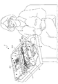
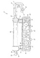
図1〜15を参照すると、本発明の血液透析システム1は、再利用式透析機械201と、使い捨てカートリッジ11と、患者の動脈へ接続するための針7を含む動脈血ライン3と、患者の静脈へ接続するための針7を含む静脈血ライン5とを含む。特に図1〜5および15を参照すると、使い捨てカートリッジ11は、血液流路15となる導管17と、透析液流路19となる導管21とを有するハウジング13を含む。好ましくは、カートリッジの血液流路および透析液流路は、内径がおよそ0.156インチ(3〜5ミリメートル)の導管である。使い捨てカートリッジ11は、単体構造でよい。しかし、好ましくは、またここで記載されるように、透析器25およびフィルタ79の解離を許容するように使い捨てカートリッジが多数の部分に分解されうるが、多数の部分が組み立てられると使い捨てカートリッジ11となる。好ましくは、カートリッジのハウジングはアメリカ食品医薬品局承認材料で製造される。カートリッジのハウジングのための現時点で好適な材料は、ポリカーボネートプラスチックである。
1-15, a
使い捨てカートリッジの血液流路15は、一端部で動脈血ライン3へ、他端部で静脈血ライン5に接続されている。血液流路15と透析液流路19の両方は透析器25を通って、半透膜(不図示)により透析液流路が血液流路から隔離されている閉ループシステムを経て、それぞれの流体を輸送する。好ましくは、透析液を受容するための入口31と、透析液を排出するための出口33と、患者から血液を受容するための入口27と、患者へ血液を戻すための出口29とを備える透析器25において、透析液が血液流と反対方向に流れる。
The
より詳しくは、また図1,3,9に図示されているように、使い捨てカートリッジのハウジング13は、透析器の入口27を動脈血ライン3へ接続するための継手37と、透析器の血液出口29を静脈血ライン5へ接続するための継手39とを含む。加えて、使い捨てカートリッジのハウジング13は、タンク209に対して透析液を出入輸送するための導管21を含むカセット区分23を含む。このために、カセット23は、継手47,43を経て透析器の入口31および出口33に接続されている。透析液は、カセットの継手47を経てカセット23に受容される。その後、透析器入口31で透析器25に入るまで、透析液は(導管21内の)透析液流路19を通る。それから透析液は透析器出口33で透析器25を出て、続いて、継手43でカセット23から出るまで、導管21内の透析液流路19を移動する。
More particularly, and as illustrated in FIGS. 1, 3, and 9, the
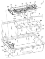
好ましくは、カートリッジのカセット23は、2個のポンプアクチュエータ51,53を備えている。第1ポンプアクチュエータ51は透析器25の上流に配置され、透析液流路19を経て透析器25へ透析液を送入する。第2ポンプアクチュエータ53は、透析器25から透析液を送入するため透析器25のほとんどすぐ下流に配置されている。第1ポンプアクチュエータ51の動作を第2ポンプアクチュエータ53に対して独立制御することにより、透析器25内での透析液流体の圧力を上昇または低下させることができる。好ましくは、使い捨てカートリッジのハウジング13は、動脈血ライン3に接続されるハウジングの継手37の中に配置される第3ポンプアクチュエータ55を含む。この第3ポンプアクチュエータ55は血液流路15を経て血液を送入し、好ましくは透析器25の上流に配置されている。
Preferably, the
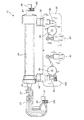
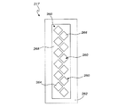
図2,7,8に最も分かりやすく図示されているように、使い捨てカートリッジ11はフィルタ79を含む。フィルタ79は、透析液体から毒素を除去するためのフィルタ材料を包囲するためのハウジング81を含む。フィルタ材料は周知の組成および構造のものであるか、様々な老廃物、主に尿素とクレアチンとを血液から除去するものとして当業者に判断されるものである。フィルタ71は、入口83と出口85とを含む。後でより詳しく記載されるように、フィルタの入口83はカセットの継手43に接続され、フィルタの出口85はタンクの入口211に接続される。好適な実施形態において、フィルタのハウジング81は、図7および8に図示された蒸気膜87を含む。蒸気膜87は、フィルタ79を流れるアンモニアを含むガスを放出できるが、液体、特に透析液体は放出できない半透膜である。
As best shown in FIGS. 2, 7, and 8, the
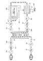
以下に詳しく記すように、使い捨てカートリッジ11は、透析器25で行われる透析を監視するための様々なセンサを備えている。図5〜10に図示されているように、好適な使い捨てカートリッジ11は、透析液流路19で透析液の流体流量および圧力を測定するための、二対の流量センサ93および圧力センサ95をカセットに含む。好ましくは、カセット流量センサ93は透析器25の上流および下流にそれぞれ配置される。好適な実施形態において、各流量センサ93は、透析液流路の円形室91と、透析液の流れにより回転される室91の中の回転スポークホイール(不図示)とを含む。好ましくは、ホイールスポークは、流体流量を判断するのに使用されるホイールの回転位置および回転速度を明らかにする反対極性の2個の磁石を含む。好ましくは、透析液圧力を測定するためのカセット圧力センサ95も、透析液が透析器25へ入る前に、また透析液が透析器25から出てから、透析液の圧力を測定するため、透析器25の上流および下流にそれぞれ配置されている。カセットの圧力および流量センサは、当業者により選択されうるアメリカ食品医薬品局承認センサでありうる。
As will be described in detail below, the
好ましくは、使い捨てカートリッジは、血液流路15を通る血液の圧力および流体流量を、患者から血液を受容した直後と患者へ血液を戻す前の両方で測定するための追加センサ97を備えている。好適な実施形態において、血液の圧力および流体流量の両方の測定は単一のセンサにより行われる。図5,9,10,13,15に最も分かりやすく図示されているように、好適なカートリッジ11は、血液が透析器25へ入る前に動脈血ライン3により受容される際に血液の圧力および流体流量を測定するための、継手37の中の第1圧力/流体センサ97を含む。加えて、好ましくは、静脈血ライン5を経て血液が患者へ戻される前に血液の圧力および流体流量を測定するための、継手39の中の第2圧力/流体センサ97をカートリッジが備える。カセット流量センサおよび圧力センサにより得られる測定値を伝えるため、使い捨てカートリッジ11は電気端子101を備えている。
Preferably, the disposable cartridge includes an
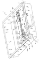
血液透析システムの透析機械201が、図1〜5に最も分かりやすく図示されている。好ましくは、透析機械201は、透析機械201および使い捨てカートリッジ11の様々な部品を包囲および保護するための空洞207を有するケース205を備えている。好ましくは、ケース205は、民間航空機の頭上荷物入れでの移動に適したサイズのものである。透析機械201は、血液透析処置中に透析液を保管するためのタンク209を備えている。好適なタンクは、タンクの着脱キャップ215を経てタンクへ導入されうる透析液を1ガロン(3.785リットル)保管する。加えて、タンク209は入口211と出口213とを含む。図7に最も分かりやすく図示されているように、タンクの入口211は使い捨てカートリッジのフィルタ出口85に接続されている。一方、タンクの出口213は使い捨てカートリッジのコネクタ47に接続されている。好ましくは、透析機械は、透析液の温度を所望の温度まで加熱して維持するためタンク209に熱的結合されているヒータ221(図15に図示)を備えている。
A dialysis machine 201 of a hemodialysis system is best illustrated in FIGS. Preferably, the dialysis machine 201 comprises a
好ましくは、透析機械201は、使い捨てカートリッジのハウジング13、透析器25、動脈ライン継手37、静脈ライン継手39を支持してこれに合体するためのトレイ219を含む。トレイ219は、透析機械210との係合状態で使い捨てカートリッジ11を固定するためのラッチ225を含みうる。好適な実施形態において、トレイ219は、使い捨てカートリッジの3個のポンプアクチュエータ(51,53,55)に結合されるための3個のポンプモータ(227,229,231)も含む。図5,6,11を参照すると、透析機械は、使い捨てカートリッジの第1ポンプアクチュエータ51と結合されるための第1ポンプモータ227と、使い捨てカートリッジの第2ポンプアクチュエータ53と結合されるための第2ポンプモータ221と、使い捨てカートリッジの第3ポンプアクチュエータ55と結合されるための第3ポンプモータ231とを含む。好ましくは、ポンプモータは、当業者により選択されるような従来の市販の回転式電動モータである。
Preferably, the dialysis machine 201 includes a
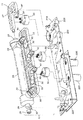
図6に図示されているように、好ましくは、各ポンプアクチュエータ(51,53,55)は、動脈ラインまたは静脈ラインと係合する通常のローラポンプとともに採用されるものなど、送入動作を提供するための変形部材を採用していない。代わりに、好適なポンプアクチュエータは、摺動ベーン構造を備えている。このために各ポンプアクチュエータは、空洞63へ流体を導入するための入口57と、このような流体を排出するための出口59とを含む。さらに、各ポンプアクチュエータは、径方向可動ベーン69を受容するためのスロット67を有する円形ロータ65を含む。遠心力、油圧、および/または、バネやプッシュロッドなどの付勢手段が空洞63の壁へベーンを押圧して、ロータとベーンと空洞側壁とにより形成される室を形成する。図6に図示された好適な実施形態では、ロータの回転により生じる遠心力が空洞側壁へベーンを押圧する。好ましくは、空洞63とロータ67とは実質的に円形であり、ロータは、より大きな空洞の中に配置される。しかし、ロータの中心と空洞の中心とは軸方向において互いにオフセット(偏心)している。動作時に、ロータ65とベーン69とはインペラを形成する。ロータが回転すると、流体は入口57を経てポンプアクチュエータへ入る。ロータおよびベーンの回転は、ポンプアクチュエータの出口59から排出されることになる流体を送入する。好ましくは、アメリカ食品医薬品局承認のプラスチックを含む実質的に変形不能な材料で各ポンプアクチュエータが製作される。ここで使用される際に、「変形不能」の語は、ポンプ動作中にポンプアクチュエータ部品がわずかな変形も受けないことを意味する意図はない。しかし、変形不能ポンプアクチュエータ部品は、現在の血液透析治療で通常は採用されているように、血液ラインなどの可撓性チューブと係合する蠕動ローラポンプにより提供されるような送入動作を提供するような形で変形することはない。好適な実施形態において、ポンプアクチュエータのハウジングとロータとはポリカーボネートで製作され、ポンプアクチュエータのベーンはポリエーテルエーテルケトン(PEEK)で製作される。
As shown in FIG. 6, preferably each pump actuator (51, 53, 55) provides a delivery action, such as that employed with a conventional roller pump that engages an arterial or venous line. The deformation member for doing is not adopted. Instead, a suitable pump actuator comprises a sliding vane structure. For this purpose, each pump actuator includes an
やはり図6を参照すると、ポンプアクチュエータのロータ63は、当業者に周知の様々な構造により電動モータ67に接続されている。例えば、ロータにより形成される対応の受容部との圧入を形成するようにキーが設けられているシャフトをロータが含みうる。しかし、図6に図示されている好適な実施形態において、モータ227とロータ65とが磁石71を利用して結合されている。図示されているように、好適なロータは、隣接の各磁石71について極性(南北方向)が交互する6個の磁石を備えている。同様に、モータ227は、各磁石の極性が交互する6個の追加磁石71を格納している。使い捨てカートリッジ11が透析機械201に結合されると、ロータ磁石と密着接触するようにモータ磁石が配置および整列される。磁力がポンプモータをポンプアクチュエータに結合するため、ポンプモータの被制御起動はロータを回転させ、こうしてポンプアクチュエータを作動させる。
Still referring to FIG. 6, the
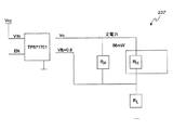
以下で詳しく記すように、使い捨てカートリッジ11に見られるセンサに加えて、好適な透析機械201は、血液透析システム1の適正動作を監視するための様々なセンサも備えている。例えば、透析機械は好ましくは、タンク209での透析液の温度を測定するための温度センサ223を含む。加えて、透析システムは、フィルタ79内のアンモニアを検出するためフィルタの蒸気膜87に隣接して配置されているアンモニアセンサ237(図15参照)を含む。図2,3,12に図示されているように、好ましくは、透析機械201はまた、やはり付加的な冗長安全性を患者に提供するため、一対のセンサ(239,241)と、静脈血ライン5に接続されたバルブ245とを含む。付加的なセンサは、静脈血ライン5での血液の圧力を測定するための圧力センサ239と、静脈血ライン5に不要な気泡が存在するかどうかを判断する気泡センサ241とを含む。血圧が所定範囲内でない場合、または不要な気泡が検出された場合には、ピンチバルブ245が閉じられる。
As will be described in detail below, in addition to the sensors found in the
図14を参照すると、透析機械201は、プロセッサ249と、ユーザインタフェース25と、プロセッサ249とユーザインタフェース251とポンプモータとセンサとへ電力を提供するための電源253とを含む。プロセッサ249は、従来の電気回路構成により、透析機械センサ(タンク液位センサ217と漏血センサ235とアンモニアセンサ237と静脈血ライン圧力センサ239と静脈血ライン気泡センサ241とを含む)と、3個のポンプモータ227,229,231と、ピンチバルブ245とに接続されている。加えて、透析機械は、プロセッサ249を使い捨てカートリッジのセンサ(流量および圧力センサを含む)と接続するように使い捨てカートリッジの電気端子101へ接続するための電気端子247(図11参照)を備えている。プロセッサは、様々なセンサを監視してヒータとポンプとピンチバルブとの自動または誘導制御を提供すると当業者に判断されるような、汎用コンピュータまたはハードウェアとソフトウェアとを含むマイクロプロセッサでよい。プロセッサは、回路基板の電子機器内に、または多数の回路基板を処理する集合体に設置されうる。
Referring to FIG. 14, the dialysis machine 201 includes a
動作時に、プロセッサ249は、ポンプモータの起動および回転速度を制御するため第1、第2、第3のポンプモータに電気接続され、ポンプモータはポンプアクチュエータを制御し、ポンプアクチュエータは血液流路での血液と透析液流路での透析液との圧力および流体速度を制御する。第1および第2ポンプアクチュエータの動作を独立制御することにより、プロセッサは、透析器における透析液流路での圧力および/または流体流量を維持、増加、または減少できる。また、3個のポンプアクチュエータすべてを独立制御することにより、プロセッサ249は透析器の半透膜での圧力差を制御して、所定の圧力差(ゼロ、正、または負)を維持するか、所定の圧力範囲を維持する。例えば、大部分の血液透析は半透膜での圧力差がゼロまたはほぼゼロで実施され、このため、プロセッサはポンプを監視および制御してこの所望のゼロまたはほぼゼロの圧力差を維持する。代替的に、プロセッサが圧力センサを監視するとともにポンプモータを制御し、またポンプアクチュエータが、透析器での透析液流路の圧力に対する透析器での血液流路の正圧を上昇および維持する。この圧力差がプロセッサによる影響を受けて、限外ろ過を行うとともに、血液から透析液への自由水および溶解溶質の移送を行うことも可能であると、有利である。
In operation, the
また、プロセッサは様々なセンサのすべてを監視して、血液透析機械が効率的かつ安全に作動することを保証し、非安全な、または非指定の条件が検出された場合には、プロセッサが欠陥を修正するか、それ以上の血液透析治療を中止する。例えば、静脈血ライン圧力センサ239が非安全な圧力を示すか、気泡センサ241が静脈血ラインでの気泡を検出した場合には、プロセッサがアラームを発し、ポンプが停止され、ピンチバルブ245が閉じられて患者への血液のさらなる流れを防止する。同様に、透析器の半透膜を血液が透過したことを漏血センサ235が検出した場合、プロセッサ249はアラームを発してさらなる血液透析治療を中止する。
The processor also monitors all of the various sensors to ensure that the hemodialysis machine operates efficiently and safely, and if an unsafe or non-designated condition is detected, the processor will fail. Correct or discontinue further hemodialysis treatment. For example, if the venous blood
透析機械のユーザインタフェース251は、患者または医療従事者が治療に関するコマンドを入力するか、患者または医療従事者が血液透析システムの性能を監視するためのキーボードまたはタッチスクリーンを含みうる。また、プロセッサは遠隔箇所への情報や制御の伝達のためのWi−Fi接続を含みうる。
The
上述したように、血液透析システム1は、これまでは血液透析器具に組み込まれたことのない多数の改良センサを取り入れている。改良センサは、アンモニアセンサ237と流体液位センサ217と漏血センサ235とを含む。これらのセンサの各々は、以下でより詳しく記載される。
As described above, the
アンモニアセンサシステム
やはり上述したように、少なくとも一つのアンモニアセンサ237は、フィルタの蒸気膜87に隣接して配置され、フィルタ79内のアンモニアを検出するように構成されている。もう少し詳しく記すと、少なくとも一実施形態において、各アンモニアセンサ237は、以下のパラメータを有するヒータ(不図示)を内蔵している。

少なくとも一つの実施形態において、アンモニアセンサ237の化学的感応膜の性質のため、ヒータからの温度上昇がアンモニアヒータ237の寿命にわたって反復可能かつ一定であることが重要である。このため、とりわけアンモニアセンサ237の寿命にわたってヒータの抵抗が変化することを把握したうえで、ヒータに印加される電力をできる限り常に制御することも重要である。少なくとも一つの実施形態において、アンモニアセンサ237は、ヒータと直列の単一の負荷抵抗器を使用する。この構成は、VCCとともにRHの変動に極めて影響を受けやすい。定格のVCC=3.3V±3.0%とRL=36.5Ω±1.0%を使用すると、以下の表で実証されているように、PH=0.0669W±10.3%(設計中心PH=0.0667W)が求められる。
少なくとも一つの実施形態では、ヒータでの電力散逸をより細かく制御するため、図16に示された回路が使用される。LDOはRLへ一定の電流を送るのに使用され、RPはRHで電流の均衡を保つのに使用される。以下の表で実証されているように、VFB=0.8V±1.25%、RL=13.0Ω±1%、RP=69.8Ω±1%、PH=0.0658W±1.65%(設計中心PH=0.0661W)である。
最大電力散逸はP(RL)=0.050WとP(RP)=0.076Wであり、これらは、1/10Wの0603抵抗器の定格動作パラメータに十分に含まれる。LDOに必要とされる最大VOUTは、3.12V(V(RH)+VFB)である。62mAでのドロップアウト電圧は〜80mVである。VCC(最小)=3.12+0.08=3.20Vであり、これは3.3V±3%のVCC電源を必要とする。 The maximum power dissipation is P (R L ) = 0.050 W and P (RP) = 0.076 W, which are well within the rated operating parameters of 1/10 W 0603 resistor. The maximum VOUT required for LDO is 3.12V (V (R H ) + V FB ). The dropout voltage at 62 mA is ~ 80 mV. V CC (minimum) = 3.12 + 0.08 = 3.20V, which requires 3.3V ± 3% VCC power supply.
少なくとも一つの実施形態において、アンモニアセンサ237の感応層は化学抵抗特性を有する。感応層の製作により、基準抵抗R0(周囲条件、合成空気)は細かく制御されない。アンダーバイアスおよび導電性が高くなると、SnO2ガス検知層は高温ではNH3(および他のガス)を減少させるので、電流検知抵抗RSを求めて周囲抵抗でこれを割ることにより、ガス検知が実施される。RS/R0比はガス濃度を表し、校正および閾値検出に使用される。感応層特徴は以下の表に示されている。
アンモニアセンサ237の出力はRL(差動)で読み取られるので、V(RL)は適正な範囲内変換についてはコンバータ(0.5V)の差動フルスケール入力範囲より下に保たれなければならない。R0のダイナミックレンジが広いため、アンモニアセンサ237の読み取りを管理するように多数の抵抗が切り換えられる必要があるのは明白である。以下は、少なくとも一つの実施形態の構成を示している。低電流が関係すると、GPIO信号はGNDであると(または反復的にGNDに近づく)と推定される。GPIOピンは、高Z条件(浮遊)のままであるか、0になる。
この構成は、感応層利得境界での適正な低下を保証するため、感応層で実用的な最高電圧を保証するのに使用される。感応層で最大の電流および電力は、以下の式により定義される。
IS=2.5/(RS+RL)=2.5/(820+200)=2.5mA
PS=IS 2*RS=0.00252*820=5.1mW
This configuration is used to ensure the highest practical voltage in the sensitive layer to ensure proper degradation at the sensitive layer gain boundary. The maximum current and power in the sensitive layer is defined by the following equation:
I S = 2.5 / (R S + R L ) = 2.5 / (820 + 200) = 2.5 mA
P S = I S 2 * R S = 0.0025 2 * 820 = 5.1 mW
ウォームアップ後に基準R0が判断されると動的範囲を増大させるのにコンバータの内部利得が使用されうることにも注目すべきである。 It should also be noted that the converter internal gain can be used to increase the dynamic range once the reference R 0 is determined after warm-up.
漏血センサ
やはり上述したように、漏血センサ235は、血液が透析器25の半透膜を透過したかどうかを検出するように配置および構成されている。もう少し詳細に記すと、少なくとも一つの実施形態において、漏血センサ235は透析液での血液の存在を判断するのに光吸収の原理を用いる。二つの別々の波長のエミッタを使用して、漏血センサ235は透析液透明性の変化を補う。
As described above, the
液位センサ
上述したように、少なくとも一つの液位センサ217は、透析液タンク209での透析流体の液位を監視および測定するように配置および構成されている(図13および15)。少なくとも一つの実施形態では、タンク209に流体が格納され、液位センサ217はタンク209の外側に隣接して配置されている。液位センサ217は、流体液位の上昇および低下について透析液タンク209を監視する際に安全重視機能を提供する。致命的な流体損失(つまりタンク209や流路19の破裂)は別にして、透析流体の利得または損失は、透析器25での圧力バランスが正しくなく、調節されなければならないことを表している。
Level Sensor As described above, at least one
もう少し詳しく記すと、少なくとも一つの実施形態において、液位センサ217は、タンク209の流体液位を判断するのに静電容量の変化を使用する。一連の電極260および接地面262がタンク209に隣接して配置され、所与の電極260での静電容量の変化は、弱導電性の透析流体の存在または不在を反映している。少なくとも一つの実施形態では、図17に図示されているように、電極260が千鳥状パターンで配設されて、電極260の間に重複が見られる。この重複は、非重複電極260よりも比較的良好な液位解像度も可能にする。電極260と接地面262(「GND」)との間の容量結合は、透析流体の存在に応じて変化する。この静電容量の変化が測定されて、すべての電極260での流体液位を判断するのに使用される。電極260のうち、液位センサ217は、透析流体の容量結合と周囲の容量結合との基準として使用される基準湿式電極264および基準乾式電極266を含む。少なくとも一つの実施形態において、正常動作中には、基準湿式電極264は常に透析流体液位より下に配置され、基準乾式電極266は常に透析流体液位より上に配置される。
More specifically, in at least one embodiment, the
続けて図17を参照すると、少なくとも一つの実施形態において、液位センサ217はさらに、電極260の各々と接地面262との間の静電容量を測定する静電容量デジタルコンバータ(不図示)を備える。液位センサ217は、従動電極260と同位相であるACシールド出力268も備え、浮遊接地結合から電極260を隔離するのに使用される。ACシールド268は、電極260の後方の平面では浮遊接地から電極260をシールドするのに、そして電極位置では各電極260について均等な負荷を保証するのに使用される。少なくとも一つの実施形態において、各電極260は90度回転した対称方形であり、全高は12mm、全幅は12mm(すべての辺が長さ8.49mmの回転方形)であり、面積は72mm2である。電極260は、電極260の中心の間で垂直方向に7.5mm離間している。この空間により表される透析流体の容積は、流体液位の断面積に比例する。例示的実施形態において、タンク209の断面積は3.102mm2である。液位の偏差により表される容積は、以下の式を用いて計算される。
Vol(ml)=3,102mm2*偏差(mm)/1000mm3/ml
例示的実施形態において、液位センサ217は、透析流体の5.8%に当たる±58mlの基本スパン(±18.75mm)を有する。
With continued reference to FIG. 17, in at least one embodiment, the
Vol (ml) = 3,102 mm 2 * deviation (mm) / 1000 mm 3 / ml
In the exemplary embodiment, the
最後になるが、ここに図示および説明された本発明の例示的実施形態に関して、携行用血液透析機械と使い捨てカートリッジが開示されていることが認識されるだろう。発明の原理は図示および説明されたもの以外の幾つかの構成で実践されうるため、発明は例示的実施形態によりいかなる点でも限定されず、概して携行用血液透析機械および使い捨てカートリッジに関するものであって、発明の趣旨および範囲を逸脱することなくこれを行うのに数多くの形を取りうることが理解されるはずである。本発明は開示された構造に特定の幾何学形状および材料に限定されず、発明の趣旨および範囲を逸脱することなく、現在周知であるか今後開発される機能的に同等の他の構造および材料を代わりに伴ってもよいことがまた当業者によって認識されるだろう。さらに、上記実施形態の各々の様々な特徴は、論理的な手法で組み合わされてもよく、本発明の範囲に含まれる意図を持つ。 Finally, it will be appreciated that a portable hemodialysis machine and a disposable cartridge are disclosed with respect to the exemplary embodiments of the present invention shown and described herein. Since the principles of the invention may be practiced in several configurations other than those shown and described, the invention is not limited in any way by exemplary embodiments and generally relates to portable hemodialysis machines and disposable cartridges. It should be understood that numerous forms of doing this can be made without departing from the spirit and scope of the invention. The present invention is not limited to the specific geometries and materials of the disclosed structure, and other functionally equivalent structures and materials now known or later developed without departing from the spirit and scope of the invention It will also be appreciated by those skilled in the art that may be accompanied instead. Further, the various features of each of the above embodiments may be combined in a logical manner and are intended to be within the scope of the present invention.
本発明の代替的な実施形態、要素、またはステップのグループ分けは、限定として解釈されてはならない。各グループの構成要素は、個別に、またはここに開示される他のグループ構成要素との組み合わせで言及および請求されうる。グループの一つ以上の構成要素は、簡便性および/または特許性を理由として、グループに内含されることも、これから削除されることもある。このような内含または削除が行われた時に、明細書はこのように変形されたグループを含有すると見なされる。 Alternative groupings of elements, elements or steps of the invention should not be construed as limiting. Each group of components may be referred to and claimed individually or in combination with other group components disclosed herein. One or more members of the group may be included in the group or deleted from it for reasons of simplicity and / or patentability. When such inclusions or deletions are made, the specification is considered to contain such modified groups.
他に指摘されない限り、本明細書および請求項で使用される特徴、物品、量、パラメータ、特性、期間、その他を表すすべての数字は、すべての事例において「約」の語により修正されるものと理解されるはずである。ここで使用される際に、「約」の語は、こうして修飾される特徴、物品、量、パラメータ、特性、または期間が、記載された特徴、物品、量、パラメータ、特性、または期間の値の上下プラスマイナス10パーセントの範囲を包含することを意味する。したがって、反対の指摘がなければ、明細書および添付請求項に提示されている数値パラメータは、変化しうる近似値である。少なくとも、また、請求項の範囲への均等論の適用を制限する意図ではなく、各数値表示は、報告された有効数字を考慮して、また通常の丸め技法を適用することにより、少なくとも解釈されるべきである。広い発明範囲で提示される数値範囲と数値とが近似値であるにも関わらず、特定例で提示される数値範囲および数値は、できる限り正確に報告される。しかし、何らかの数値範囲または数値は、それぞれの試験測定に見られる標準偏差から必然的に生じるある種の誤差を本質的に含む。ここでの値の数値範囲の記載は、範囲に含まれる別々の数値の各々に個別に言及することに代わる短縮方法として機能することを意図しているに過ぎない。他に指摘がなければ、数値範囲の各個別値は、個々に記載されているかのように本明細書に取り入れられる。 Unless otherwise indicated, all numbers representing features, articles, quantities, parameters, characteristics, periods, etc. used in the specification and claims shall be modified by the word “about” in all cases. Should be understood. As used herein, the term “about” refers to the value of the feature, article, quantity, parameter, property, or period described in the feature, article, quantity, parameter, property, or period described. It is meant to encompass a range of plus or minus 10 percent above and below. Accordingly, unless indicated to the contrary, the numerical parameters presented in the specification and appended claims are approximations that can vary. At least, and not intended to limit the application of the doctrine of equivalents to the scope of the claims, each numerical representation is interpreted at least by considering the reported significant figures and applying normal rounding techniques. Should be. Although the numerical ranges and numerical values presented in the broad scope of the invention are approximate values, the numerical ranges and numerical values presented in the specific examples are reported as accurately as possible. Any numerical range or numerical value, however, inherently contains certain errors necessarily resulting from the standard deviation found in their respective testing measurements. The description of a numerical range of values herein is intended only to serve as a shortening method instead of individually referring to each of the different numerical values included in the range. Unless otherwise indicated, each individual value in a numerical range is incorporated herein as if it were individually described.
本発明を説明する文脈で(特に以下の請求項の文脈で)使用される「a」、「an」、「the」、および類似の指示対象は、他に指摘がないか文脈との矛盾が明白でない限り、単数と複数の両方を含むものと解釈される。ここに記載されるすべての方法は、他に指摘されないか文脈との矛盾が明白でない限り、適当な順序で実施されうる。ここに挙げられるいずれかまたすべての例や例示的文言の使用(例えば「など」)は、本発明をより明確にすることのみを意図したものであって、他に請求された発明の範囲に限定を加えるものではない。本明細書のいかなる文言も、発明の実施について本質的である非請求要素を指すと解釈されるべきではない。 “A”, “an”, “the”, and similar designations used in the context of describing the present invention (especially in the context of the following claims) are subject to conflict or contradiction to the context. Unless expressly stated, it is intended to include both singular and plural. All methods described herein can be performed in any suitable order unless otherwise indicated herein or otherwise contradicted by context. Use of any and all examples or exemplary language (eg, “etc.”) herein is intended only to clarify the invention and is within the scope of other claimed inventions. There is no limitation. No language in the specification should be construed as referring to unclaimed elements that are essential to the practice of the invention.
ここに開示される特定の実施形態は、文言を使用するか文言で構成されるか本質的に文言で構成される請求項でさらに限定されうる。請求項で使用される時には、出願時のものであっても補正で追加されるものであっても、接続句である「〜で構成される」は、請求項に明記されていない要素、ステップ、または成分を除外する。接続句「〜で本質的に構成される」は、指定された材料またはステップと、基本的で新規の特徴に実質的な影響を与えないものとに、請求項の範囲を限定する。このように請求された本発明の実施形態は、本質的または明白に記載され、ここで実行可能である。 Particular embodiments disclosed herein may be further limited in the claims that use, consist of, or consist essentially of the wording. When used in a claim, whether it is as filed or added in an amendment, the connective phrase “consisting of” is an element, step not specified in the claim Or exclude ingredients. The connection phrase “consisting essentially of” limits the scope of the claims to the specified materials or steps and to those that do not substantially affect the basic novel features. The embodiments of the invention thus claimed are described in nature or expressly and can be practiced here.
論理コード、プログラム、モジュール、プロセス、方法、そして各方法のそれぞれの要素が実施される順序は純粋に例示的であると理解されるべきである。実行例に応じて、本開示で他に指摘されない限り、これらはいかなる順序でも、また並行して実施されうる。さらに、論理コードは特定のプログラミング言語に関連しないか限定されず、分散型、非分散型、またはマルチ処理の環境において一つ以上のプロセッサで実行される一つ以上のモジュールを含みうる。 It should be understood that the logic code, programs, modules, processes, methods, and the order in which the respective elements of each method are implemented are purely exemplary. Depending on the implementation, these may be performed in any order and in parallel, unless otherwise noted in this disclosure. Further, the logical code is not related or limited to a particular programming language, and may include one or more modules that execute on one or more processors in a distributed, non-distributed, or multi-processing environment.
発明の幾つかの特定の形態が図示および説明されたが、発明の趣旨および範囲を逸脱することなく様々な変形が行われうることは明白であろう。そのため、以下の請求項を除いて発明が限定されることは意図されていない。 While several particular forms of the invention have been illustrated and described, it will be apparent that various modifications can be made without departing from the spirit and scope of the invention. Therefore, it is not intended that the invention be limited except in the following claims.
1 血液透析システム
3 動脈血ライン
5 静脈血ライン
7 針
11 使い捨てカートリッジ
13 ハウジング
15 血液流路
17 導管
19 透析液流路
23 カセット
25 透析器
31 入口
33 出口
37,39,43,47 継手
51,53,55 ポンプアクチュエータ
57 入口
59 出口
63 空洞
65 円形ロータ
67 スロット
69 ベーン
71 磁石
79 フィルタ
81 ハウジング
83 入口
85 出口
87 蒸気膜
93 流量センサ
95 圧力センサ
97 第1圧力/流体センサ
101 電気端子
205 ケース
207 空洞
209 タンク
211 入口
213 出口
215 着脱キャップ
217 タンク液位センサ
219 トレイ
221 ヒータ
223 温度センサ
225 ラッチ
227,229,231 ポンプモータ
235 漏血センサ
237 アンモニアセンサ
239 静脈血ライン圧力センサ
241 静脈血ライン気泡センサ
245 ピンチバルブ
247 電気端子
249 プロセッサ
251 ユーザインタフェース
253 電源
260 電極
262 接地面
264 湿式基準電極
266 乾式基準電極
268 ACシールド出力
DESCRIPTION OF
Claims (6)
患者へ血液を戻すため患者の静脈に接続される静脈血ラインと、
透析器と、
患者から前記透析器へ、そして再び患者へ血液を輸送するため、前記動脈血ラインおよび前記静脈血ラインに接続されている血液流路と、
透析溶液を保管するためのタンクと、
前記タンクから前記透析器へ、そして再び前記タンクへ透析液を輸送するため、前記血液流路から隔離されている透析液流路と、
前記透析器の後で前記透析液を前記タンクへ戻す前に、前記透析液流路の透析液から尿毒症毒素を除去するため、前記透析器の下流で前記透析液流路に接続されているフィルタと、
第1ポンプモータと第1ポンプアクチュエータとを含み、前記透析液流路を経て前記透析器へ透析液を送入するため前記透析器の上流で前記透析液流路に接続されている第1ポンプであって、前記第1ポンプアクチュエータが、内部側壁を形成する中央空洞を有するハウジングと、前記空洞に偏心状態で配置されているロータとを含む非変形部品を有する摺動ベーン構造を含み、前記ロータが、前記ロータの周囲で径方向に整列された複数のスロットと、前記スロットに摺動可能に配置され、前記空洞の内部側壁と密閉を行って前記透析液流路を経て透析液を送入するベーン室を作成するため前記スロットに対して出入摺動するように前記スロットに摺動可能に配置されたベーンとを有する、第1ポンプと、
第2ポンプモータと第2ポンプアクチュエータとを含み、前記透析液流路を経て透析液を送入するため前記透析器の上流で前記透析液流路に接続されている第2ポンプであって、前記第2ポンプアクチュエータが、内部側壁を形成する中央空洞を有するハウジングと、前記空洞に偏心状態で配置されているロータとを含む非変形部品を有する摺動ベーン構造を含み、前記ロータが、前記ロータの周囲で径方向に整列された複数のスロットと、前記スロットに摺動可能に配置され、前記空洞の内部側壁と密閉を行って前記透析液流路を経て透析液を送入するベーン室を作成するため前記スロットに対して出入摺動するように前記スロットに摺動可能に配置されたベーンとを有する、第2ポンプと、
第3ポンプモータと第3ポンプアクチュエータとを含み、前記血液流路を経て血液を送入するため前記血液流路に接続されている第3ポンプであって、前記第3ポンプアクチュエータが、内部側壁を形成する中央空洞を有するハウジングと、前記空洞に偏心状態で配置されているロータとを含む非変形部品を有する摺動ベーン構造を含み、前記ロータが、前記ロータの周囲で径方向に整列された複数のスロットと、前記スロットに摺動可能に配置され、前記空洞の内部側壁と密閉を行って前記血液流路を経て血液を送入するベーン室を作成するため前記スロットに対して出入摺動するように前記スロットに摺動可能に配置されたベーンとを有する、第3ポンプと、
前記ポンプモータの動作を制御するため前記第1、第2、および第3のポンプモータに接続されているプロセッサと、
を含む、血液透析システム。 An arterial blood line connected to the patient's artery to collect blood from the patient;
A venous blood line connected to the patient's vein to return blood to the patient;
A dialyzer,
A blood flow path connected to the arterial blood line and the venous blood line for transporting blood from the patient to the dialyzer and back to the patient;
A tank for storing the dialysis solution;
A dialysate flow path isolated from the blood flow path for transporting dialysate from the tank to the dialyzer and back to the tank;
Connected to the dialysate channel downstream of the dialyzer to remove uremic toxins from the dialysate in the dialysate channel before returning the dialysate to the tank after the dialyzer Filters,
A first pump including a first pump motor and a first pump actuator and connected to the dialysate flow path upstream of the dialyzer for delivering dialysate to the dialyzer via the dialysate flow path The first pump actuator includes a sliding vane structure having a non-deformable part including a housing having a central cavity forming an inner side wall and a rotor arranged eccentrically in the cavity; A rotor is arranged in a plurality of slots radially arranged around the rotor, and is slidably disposed in the slot. The rotor seals the inner side wall of the cavity and sends the dialysate through the dialysate flow path. A first pump having a vane slidably disposed in the slot to slide into and out of the slot to create a vane chamber to enter;
A second pump that includes a second pump motor and a second pump actuator, and is connected to the dialysate flow path upstream of the dialyzer for feeding dialysate through the dialysate flow path; The second pump actuator includes a sliding vane structure having a non-deformable part including a housing having a central cavity forming an inner side wall and a rotor arranged eccentrically in the cavity, wherein the rotor includes the rotor A plurality of slots radially aligned around the rotor, and a vane chamber that is slidably disposed in the slot and seals the inner side wall of the cavity and feeds dialysate through the dialysate flow path A second pump having a vane slidably disposed in the slot to slide in and out of the slot to create
A third pump including a third pump motor and a third pump actuator and connected to the blood flow path for feeding blood through the blood flow path, the third pump actuator having an inner sidewall A sliding vane structure having a non-deformable part including a housing having a central cavity forming a rotor and a rotor disposed eccentrically in the cavity, wherein the rotor is radially aligned around the rotor A plurality of slots, and a slot that is slidably disposed in the slots, seals the inner side wall of the cavity, and slides in and out of the slots to create a vane chamber for feeding blood through the blood channel. A third pump having a vane slidably disposed in the slot for movement;
A processor connected to the first, second, and third pump motors for controlling operation of the pump motor;
Including a hemodialysis system.
再利用式透析機械および使い捨てカートリッジであって、前記使い捨てカートリッジが前記再利用式透析機械に対して接続および分断可能である、再利用式透析機械および使い捨てカートリッジ、
を含み、
前記第1、第2、および第3のポンプモータが前記再利用式透析機械に配置され、前記第1、第2、および第3のポンプアクチュエータが前記使い捨てカートリッジに配置される、
請求項1の血液透析システム。 further,
A reusable dialysis machine and a disposable cartridge, wherein the disposable cartridge is connectable and disconnectable to the reusable dialysis machine;
Including
The first, second, and third pump motors are disposed on the reusable dialysis machine, and the first, second, and third pump actuators are disposed on the disposable cartridge;
The hemodialysis system according to claim 1.
Applications Claiming Priority (3)
| Application Number | Priority Date | Filing Date | Title |
|---|---|---|---|
| US201461945698P | 2014-02-27 | 2014-02-27 | |
| US61/945,698 | 2014-02-27 | ||
| PCT/US2015/017744 WO2015130927A1 (en) | 2014-02-27 | 2015-02-26 | Portable hemodialysis machine and disposable cartridge |
Publications (2)
| Publication Number | Publication Date |
|---|---|
| JP2017512114A true JP2017512114A (en) | 2017-05-18 |
| JP2017512114A5 JP2017512114A5 (en) | 2017-08-10 |
Family
ID=53881214
Family Applications (2)
| Application Number | Title | Priority Date | Filing Date |
|---|---|---|---|
| JP2016572355A Pending JP2017512114A (en) | 2014-02-27 | 2015-02-26 | Portable hemodialysis machine and disposable cartridge |
| JP2016572353A Ceased JP2017510396A (en) | 2014-02-27 | 2015-02-26 | Portable hemodialysis machine and disposable cartridge |
Family Applications After (1)
| Application Number | Title | Priority Date | Filing Date |
|---|---|---|---|
| JP2016572353A Ceased JP2017510396A (en) | 2014-02-27 | 2015-02-26 | Portable hemodialysis machine and disposable cartridge |
Country Status (17)
| Country | Link |
|---|---|
| US (2) | US9364599B2 (en) |
| EP (2) | EP3110471A4 (en) |
| JP (2) | JP2017512114A (en) |
| KR (2) | KR101768874B1 (en) |
| CN (2) | CN106061523B (en) |
| AP (2) | AP2016009460A0 (en) |
| AU (2) | AU2015222971B2 (en) |
| CA (2) | CA2939155C (en) |
| CL (2) | CL2016002160A1 (en) |
| CU (2) | CU20160124A7 (en) |
| EC (2) | ECSP16076606A (en) |
| IL (2) | IL247496A (en) |
| MX (2) | MX2016010736A (en) |
| PE (2) | PE20161241A1 (en) |
| SG (2) | SG11201607056WA (en) |
| WO (2) | WO2015130906A1 (en) |
| ZA (1) | ZA201606042B (en) |
Families Citing this family (23)
| Publication number | Priority date | Publication date | Assignee | Title |
|---|---|---|---|---|
| ES2864727T3 (en) | 2014-04-29 | 2021-10-14 | Outset Medical Inc | Dialysis system and methods |
| FR3042974B1 (en) * | 2015-11-04 | 2017-12-08 | Isp Investments Inc | SYNERGISTIC EXTRACT OF PALMARIA PALMATA AND JASMIN, COMPOSITIONS COMPRISING THE SAME AND USES THEREOF |
| CN105709291B (en) * | 2016-01-07 | 2018-12-04 | 王贵霞 | A kind of Intelligent blood diafiltration device |
| US11534537B2 (en) | 2016-08-19 | 2022-12-27 | Outset Medical, Inc. | Peritoneal dialysis system and methods |
| GB2554414A (en) * | 2016-09-26 | 2018-04-04 | Quanta Dialysis Technologies Ltd | Liquid preparation for use in dialysis |
| CN108720885B (en) * | 2017-04-20 | 2021-02-05 | 南台科技大学 | Hemostatic device |
| EP3634528B1 (en) | 2017-06-07 | 2023-06-07 | Shifamed Holdings, LLC | Intravascular fluid movement devices, systems, and methods of use |
| US10682455B2 (en) | 2017-07-11 | 2020-06-16 | Fresenius Medical Care Holdings, Inc. | Fluid leak detection in a dialysis machine |
| WO2019016904A1 (en) * | 2017-07-19 | 2019-01-24 | 株式会社ジェイ・エム・エス | Flow passage opening/closing mechanism, and peritoneum dialysis device provided with said flow passage opening/closing mechanism |
| CN111556763B (en) | 2017-11-13 | 2023-09-01 | 施菲姆德控股有限责任公司 | Intravascular fluid movement device and system |
| CN111565772A (en) * | 2017-12-06 | 2020-08-21 | 费森尤斯医疗护理德国有限责任公司 | Movable dialysis chair |
| DE102018100568A1 (en) * | 2018-01-11 | 2019-07-11 | B. Braun Avitum Ag | Blood treatment machine with a hollow fiber filter module for horizontal arrangement and a hollow fiber filter module and its use |
| JP7410034B2 (en) | 2018-02-01 | 2024-01-09 | シファメド・ホールディングス・エルエルシー | Intravascular blood pump and methods of use and manufacture |
| CN109238571B (en) * | 2018-10-30 | 2020-06-23 | 浙江师范大学 | Trace blood leakage monitoring device and method for blood purification system |
| US20200375471A1 (en) * | 2019-05-31 | 2020-12-03 | iTrend Medical Research Limited | System and method for measuring pressure waves in dialysis lines |
| WO2021016372A1 (en) | 2019-07-22 | 2021-01-28 | Shifamed Holdings, Llc | Intravascular blood pumps with struts and methods of use and manufacture |
| EP4034192A4 (en) | 2019-09-25 | 2023-11-29 | Shifamed Holdings, LLC | Intravascular blood pump systems and methods of use and control thereof |
| US20210128801A1 (en) * | 2019-11-05 | 2021-05-06 | Diality Inc. | Syringe pump |
| EP4054698A4 (en) * | 2019-11-05 | 2023-12-06 | Diality Inc. | Disposable cartridge and pump track mechanism |
| WO2021096706A1 (en) | 2019-11-12 | 2021-05-20 | Fresenius Medical Care Deutschland Gmbh | Blood treatment systems |
| WO2021094140A1 (en) | 2019-11-12 | 2021-05-20 | Fresenius Medical Care Deutschland Gmbh | Blood treatment systems |
| EP4058094A1 (en) | 2019-11-12 | 2022-09-21 | Fresenius Medical Care Deutschland GmbH | Blood treatment systems |
| CA3160952A1 (en) | 2019-11-12 | 2021-05-20 | Fresenius Medical Care Deutschland Gmbh | Blood treatment systems |
Citations (4)
| Publication number | Priority date | Publication date | Assignee | Title |
|---|---|---|---|---|
| JP2002147371A (en) * | 2000-08-31 | 2002-05-22 | Jigyo Sozo Kenkyusho:Kk | Vane pump |
| JP2008255984A (en) * | 2007-03-15 | 2008-10-23 | Matsushita Electric Works Ltd | Vane pump |
| JP2008540018A (en) * | 2005-05-19 | 2008-11-20 | イペルボレアル ファルマ エス.アール.エル | Blood filtration device |
| WO2012108910A1 (en) * | 2011-02-08 | 2012-08-16 | Fresenius Medical Care Holdings, Inc. | Portable dialysis machine |
Family Cites Families (35)
| Publication number | Priority date | Publication date | Assignee | Title |
|---|---|---|---|---|
| CS200909B1 (en) | 1977-12-23 | 1980-10-31 | Petr Slovak | Haemodlialysation device |
| US4650587A (en) | 1982-09-09 | 1987-03-17 | Akzona Incorporated | Ammonia scavenger |
| US4661246A (en) | 1984-10-01 | 1987-04-28 | Ash Medical Systems, Inc. | Dialysis instrument with dialysate side pump for moving body fluids |
| US5336165A (en) | 1991-08-21 | 1994-08-09 | Twardowski Zbylut J | Artificial kidney for frequent (daily) Hemodialysis |
| US5902476A (en) | 1991-08-21 | 1999-05-11 | Twardowski; Zbylut J. | Artificial kidney for frequent (daily) hemodialysis |
| US6471872B2 (en) * | 1991-10-11 | 2002-10-29 | Children's Hospital Medical Center | Hemofiltration system and method based on monitored patient parameters |
| US5944684A (en) | 1995-08-31 | 1999-08-31 | The Regents Of The University Of California | Wearable peritoneum-based system for continuous renal function replacement and other biomedical applications |
| US5858186A (en) | 1996-12-20 | 1999-01-12 | The Regents Of The University Of California | Urea biosensor for hemodialysis monitoring |
| US7241272B2 (en) | 2001-11-13 | 2007-07-10 | Baxter International Inc. | Method and composition for removing uremic toxins in dialysis processes |
| US7890341B2 (en) | 2002-12-09 | 2011-02-15 | Baxter International Inc. | System and a method for providing integrated access management for peritoneal dialysis and hemodialysis |
| US6979306B2 (en) * | 2003-08-13 | 2005-12-27 | Moll Family Trust | Method and device for monitoring loss of body fluid and dislodgment of medical instrument from body |
| MX351817B (en) | 2003-10-28 | 2017-10-30 | Baxter Healthcare Sa | Improved priming, integrity and head height methods and apparatuses for medical fluid systems. |
| US8029454B2 (en) | 2003-11-05 | 2011-10-04 | Baxter International Inc. | High convection home hemodialysis/hemofiltration and sorbent system |
| US8038639B2 (en) | 2004-11-04 | 2011-10-18 | Baxter International Inc. | Medical fluid system with flexible sheeting disposable unit |
| BRPI0611042A2 (en) * | 2005-05-06 | 2010-12-14 | Imi Vision Ltd | disposable cartridge and dialysis machine |
| US20100089807A1 (en) | 2006-05-08 | 2010-04-15 | Keith James Heyes | Dialysis machine |
| US8109893B2 (en) | 2006-12-19 | 2012-02-07 | Lande Arnold J | Chronic access system for extracorporeal treatment of blood including a continously wearable hemodialyzer |
| US7901376B2 (en) | 2007-07-05 | 2011-03-08 | Baxter International Inc. | Dialysis cassette having multiple outlet valve |
| US7955295B2 (en) | 2007-07-05 | 2011-06-07 | Baxter International Inc. | Fluid delivery system with autoconnect features |
| US8496609B2 (en) | 2007-07-05 | 2013-07-30 | Baxter International Inc. | Fluid delivery system with spiked cassette |
| US8512553B2 (en) | 2007-07-05 | 2013-08-20 | Baxter International Inc. | Extracorporeal dialysis ready peritoneal dialysis machine |
| US20090120864A1 (en) * | 2007-10-05 | 2009-05-14 | Barry Neil Fulkerson | Wearable dialysis methods and devices |
| JP5409645B2 (en) | 2007-11-16 | 2014-02-05 | フレセニウス メディカル ケア ホールディングス インコーポレーテッド | Dialysis system |
| CA2706919C (en) | 2007-11-29 | 2018-03-06 | Fresenius Medical Care Holdings, Inc. | System and method for conducting hemodialysis and hemofiltration |
| DE102008038097A1 (en) | 2008-08-18 | 2010-02-25 | Fresenius Medical Care Deutschland Gmbh | Cassette for conveying liquids, in particular dialysis liquids |
| US8409444B2 (en) | 2008-09-30 | 2013-04-02 | Fresenius Medical Care Holdings, Inc. | Acid zirconium phosphate and alkaline hydrous zirconium oxide materials for sorbent dialysis |
| CA2976872C (en) * | 2008-10-07 | 2021-04-13 | Fresenius Medical Care Holdings, Inc. | Priming system and method for dialysis systems |
| WO2010062716A2 (en) | 2008-11-03 | 2010-06-03 | Fresenius Medical Care Holdings, Inc. | Portable peritoneal dialysis system |
| US20100312172A1 (en) * | 2009-06-06 | 2010-12-09 | Hoffman Josef C A | Method of Peritoneal Dialysis |
| US8753515B2 (en) | 2009-12-05 | 2014-06-17 | Home Dialysis Plus, Ltd. | Dialysis system with ultrafiltration control |
| KR101090414B1 (en) | 2010-02-23 | 2011-12-06 | 최낙명 | Dialysate pump and blood dialyzing apparatus having the same |
| GB201019228D0 (en) * | 2010-11-15 | 2010-12-29 | Corp | Dialysis device and method of dialysis |
| GB2498925A (en) | 2012-01-06 | 2013-08-07 | Richard Weatherley | Vane pump with magnetic coupling |
| CN104168934B (en) | 2012-01-19 | 2016-08-17 | 贝克斯特国际公司 | For removing the method and composition of the uremic toxins in dialysis procedure |
| USD706836S1 (en) | 2013-11-04 | 2014-06-10 | Renato Giordano | Pump head and pump motor housing |
-
2015
- 2015-02-26 CN CN201580010630.XA patent/CN106061523B/en not_active Expired - Fee Related
- 2015-02-26 AP AP2016009460A patent/AP2016009460A0/en unknown
- 2015-02-26 PE PE2016001525A patent/PE20161241A1/en not_active Application Discontinuation
- 2015-02-26 CU CUP2016000124A patent/CU20160124A7/en unknown
- 2015-02-26 KR KR1020167026619A patent/KR101768874B1/en active IP Right Grant
- 2015-02-26 AP AP2016009454A patent/AP2016009454A0/en unknown
- 2015-02-26 AU AU2015222971A patent/AU2015222971B2/en not_active Ceased
- 2015-02-26 PE PE2016001526A patent/PE20161123A1/en not_active Application Discontinuation
- 2015-02-26 CA CA2939155A patent/CA2939155C/en not_active Expired - Fee Related
- 2015-02-26 JP JP2016572355A patent/JP2017512114A/en active Pending
- 2015-02-26 CA CA2939152A patent/CA2939152C/en not_active Expired - Fee Related
- 2015-02-26 US US14/632,163 patent/US9364599B2/en active Active
- 2015-02-26 CU CUP2016000123A patent/CU20160123A7/en unknown
- 2015-02-26 US US14/632,421 patent/US9180237B2/en active Active
- 2015-02-26 WO PCT/US2015/017695 patent/WO2015130906A1/en active Application Filing
- 2015-02-26 SG SG11201607056WA patent/SG11201607056WA/en unknown
- 2015-02-26 MX MX2016010736A patent/MX2016010736A/en active IP Right Grant
- 2015-02-26 KR KR1020167026616A patent/KR101737769B1/en active IP Right Grant
- 2015-02-26 WO PCT/US2015/017744 patent/WO2015130927A1/en active Application Filing
- 2015-02-26 MX MX2016010625A patent/MX2016010625A/en unknown
- 2015-02-26 SG SG11201607127QA patent/SG11201607127QA/en unknown
- 2015-02-26 EP EP15755508.7A patent/EP3110471A4/en not_active Withdrawn
- 2015-02-26 CN CN201580010623.XA patent/CN106061545A/en active Pending
- 2015-02-26 EP EP15755104.5A patent/EP3110494A4/en not_active Withdrawn
- 2015-02-26 JP JP2016572353A patent/JP2017510396A/en not_active Ceased
- 2015-02-26 AU AU2015222992A patent/AU2015222992B2/en not_active Ceased
-
2016
- 2016-08-25 IL IL247496A patent/IL247496A/en not_active IP Right Cessation
- 2016-08-25 IL IL247494A patent/IL247494A/en not_active IP Right Cessation
- 2016-08-26 CL CL2016002160A patent/CL2016002160A1/en unknown
- 2016-08-26 CL CL2016002161A patent/CL2016002161A1/en unknown
- 2016-08-31 ZA ZA2016/06042A patent/ZA201606042B/en unknown
- 2016-09-23 EC ECIEPI201676606A patent/ECSP16076606A/en unknown
- 2016-09-23 EC ECIEPI201676635A patent/ECSP16076635A/en unknown
Patent Citations (4)
| Publication number | Priority date | Publication date | Assignee | Title |
|---|---|---|---|---|
| JP2002147371A (en) * | 2000-08-31 | 2002-05-22 | Jigyo Sozo Kenkyusho:Kk | Vane pump |
| JP2008540018A (en) * | 2005-05-19 | 2008-11-20 | イペルボレアル ファルマ エス.アール.エル | Blood filtration device |
| JP2008255984A (en) * | 2007-03-15 | 2008-10-23 | Matsushita Electric Works Ltd | Vane pump |
| WO2012108910A1 (en) * | 2011-02-08 | 2012-08-16 | Fresenius Medical Care Holdings, Inc. | Portable dialysis machine |
Also Published As
Similar Documents
| Publication | Publication Date | Title |
|---|---|---|
| JP2017512114A (en) | Portable hemodialysis machine and disposable cartridge | |
| US10172989B2 (en) | Portable hemodialysis machine and disposable cartridge with blood leak sensor | |
| US10980929B2 (en) | Hemodialysis system with ultrafiltration controller |
Legal Events
| Date | Code | Title | Description |
|---|---|---|---|
| A521 | Request for written amendment filed |
Free format text: JAPANESE INTERMEDIATE CODE: A523 Effective date: 20170630 |
|
| A131 | Notification of reasons for refusal |
Free format text: JAPANESE INTERMEDIATE CODE: A131 Effective date: 20171031 |
|
| A601 | Written request for extension of time |
Free format text: JAPANESE INTERMEDIATE CODE: A601 Effective date: 20180130 |
|
| A521 | Request for written amendment filed |
Free format text: JAPANESE INTERMEDIATE CODE: A523 Effective date: 20180501 |
|
| A02 | Decision of refusal |
Free format text: JAPANESE INTERMEDIATE CODE: A02 Effective date: 20181023 |