JP2017500171A - Osmotic drug delivery device, kit and method - Google Patents
Osmotic drug delivery device, kit and method Download PDFInfo
- Publication number
- JP2017500171A JP2017500171A JP2016552464A JP2016552464A JP2017500171A JP 2017500171 A JP2017500171 A JP 2017500171A JP 2016552464 A JP2016552464 A JP 2016552464A JP 2016552464 A JP2016552464 A JP 2016552464A JP 2017500171 A JP2017500171 A JP 2017500171A
- Authority
- JP
- Japan
- Prior art keywords
- fluid
- drug
- reservoir
- tube
- elongated tube
- Prior art date
- Legal status (The legal status is an assumption and is not a legal conclusion. Google has not performed a legal analysis and makes no representation as to the accuracy of the status listed.)
- Pending
Links
Images


Classifications
-
- A—HUMAN NECESSITIES
- A61—MEDICAL OR VETERINARY SCIENCE; HYGIENE
- A61M—DEVICES FOR INTRODUCING MEDIA INTO, OR ONTO, THE BODY; DEVICES FOR TRANSDUCING BODY MEDIA OR FOR TAKING MEDIA FROM THE BODY; DEVICES FOR PRODUCING OR ENDING SLEEP OR STUPOR
- A61M31/00—Devices for introducing or retaining media, e.g. remedies, in cavities of the body
- A61M31/002—Devices for releasing a drug at a continuous and controlled rate for a prolonged period of time
-
- A—HUMAN NECESSITIES
- A61—MEDICAL OR VETERINARY SCIENCE; HYGIENE
- A61K—PREPARATIONS FOR MEDICAL, DENTAL OR TOILETRY PURPOSES
- A61K31/00—Medicinal preparations containing organic active ingredients
- A61K31/70—Carbohydrates; Sugars; Derivatives thereof
- A61K31/7042—Compounds having saccharide radicals and heterocyclic rings
- A61K31/7052—Compounds having saccharide radicals and heterocyclic rings having nitrogen as a ring hetero atom, e.g. nucleosides, nucleotides
- A61K31/706—Compounds having saccharide radicals and heterocyclic rings having nitrogen as a ring hetero atom, e.g. nucleosides, nucleotides containing six-membered rings with nitrogen as a ring hetero atom
- A61K31/7064—Compounds having saccharide radicals and heterocyclic rings having nitrogen as a ring hetero atom, e.g. nucleosides, nucleotides containing six-membered rings with nitrogen as a ring hetero atom containing condensed or non-condensed pyrimidines
- A61K31/7068—Compounds having saccharide radicals and heterocyclic rings having nitrogen as a ring hetero atom, e.g. nucleosides, nucleotides containing six-membered rings with nitrogen as a ring hetero atom containing condensed or non-condensed pyrimidines having oxo groups directly attached to the pyrimidine ring, e.g. cytidine, cytidylic acid
-
- A—HUMAN NECESSITIES
- A61—MEDICAL OR VETERINARY SCIENCE; HYGIENE
- A61K—PREPARATIONS FOR MEDICAL, DENTAL OR TOILETRY PURPOSES
- A61K9/00—Medicinal preparations characterised by special physical form
- A61K9/0002—Galenical forms characterised by the drug release technique; Application systems commanded by energy
- A61K9/0004—Osmotic delivery systems; Sustained release driven by osmosis, thermal energy or gas
-
- A—HUMAN NECESSITIES
- A61—MEDICAL OR VETERINARY SCIENCE; HYGIENE
- A61K—PREPARATIONS FOR MEDICAL, DENTAL OR TOILETRY PURPOSES
- A61K9/00—Medicinal preparations characterised by special physical form
- A61K9/0012—Galenical forms characterised by the site of application
- A61K9/0034—Urogenital system, e.g. vagina, uterus, cervix, penis, scrotum, urethra, bladder; Personal lubricants
-
- A—HUMAN NECESSITIES
- A61—MEDICAL OR VETERINARY SCIENCE; HYGIENE
- A61K—PREPARATIONS FOR MEDICAL, DENTAL OR TOILETRY PURPOSES
- A61K9/00—Medicinal preparations characterised by special physical form
- A61K9/20—Pills, tablets, discs, rods
-
- A—HUMAN NECESSITIES
- A61—MEDICAL OR VETERINARY SCIENCE; HYGIENE
- A61K—PREPARATIONS FOR MEDICAL, DENTAL OR TOILETRY PURPOSES
- A61K9/00—Medicinal preparations characterised by special physical form
- A61K9/20—Pills, tablets, discs, rods
- A61K9/2004—Excipients; Inactive ingredients
- A61K9/2009—Inorganic compounds
-
- A—HUMAN NECESSITIES
- A61—MEDICAL OR VETERINARY SCIENCE; HYGIENE
- A61K—PREPARATIONS FOR MEDICAL, DENTAL OR TOILETRY PURPOSES
- A61K9/00—Medicinal preparations characterised by special physical form
- A61K9/20—Pills, tablets, discs, rods
- A61K9/2004—Excipients; Inactive ingredients
- A61K9/2013—Organic compounds, e.g. phospholipids, fats
- A61K9/2018—Sugars, or sugar alcohols, e.g. lactose, mannitol; Derivatives thereof, e.g. polysorbates
-
- A—HUMAN NECESSITIES
- A61—MEDICAL OR VETERINARY SCIENCE; HYGIENE
- A61L—METHODS OR APPARATUS FOR STERILISING MATERIALS OR OBJECTS IN GENERAL; DISINFECTION, STERILISATION OR DEODORISATION OF AIR; CHEMICAL ASPECTS OF BANDAGES, DRESSINGS, ABSORBENT PADS OR SURGICAL ARTICLES; MATERIALS FOR BANDAGES, DRESSINGS, ABSORBENT PADS OR SURGICAL ARTICLES
- A61L31/00—Materials for other surgical articles, e.g. stents, stent-grafts, shunts, surgical drapes, guide wires, materials for adhesion prevention, occluding devices, surgical gloves, tissue fixation devices
- A61L31/04—Macromolecular materials
- A61L31/06—Macromolecular materials obtained otherwise than by reactions only involving carbon-to-carbon unsaturated bonds
-
- A—HUMAN NECESSITIES
- A61—MEDICAL OR VETERINARY SCIENCE; HYGIENE
- A61L—METHODS OR APPARATUS FOR STERILISING MATERIALS OR OBJECTS IN GENERAL; DISINFECTION, STERILISATION OR DEODORISATION OF AIR; CHEMICAL ASPECTS OF BANDAGES, DRESSINGS, ABSORBENT PADS OR SURGICAL ARTICLES; MATERIALS FOR BANDAGES, DRESSINGS, ABSORBENT PADS OR SURGICAL ARTICLES
- A61L31/00—Materials for other surgical articles, e.g. stents, stent-grafts, shunts, surgical drapes, guide wires, materials for adhesion prevention, occluding devices, surgical gloves, tissue fixation devices
- A61L31/08—Materials for coatings
- A61L31/10—Macromolecular materials
-
- A—HUMAN NECESSITIES
- A61—MEDICAL OR VETERINARY SCIENCE; HYGIENE
- A61L—METHODS OR APPARATUS FOR STERILISING MATERIALS OR OBJECTS IN GENERAL; DISINFECTION, STERILISATION OR DEODORISATION OF AIR; CHEMICAL ASPECTS OF BANDAGES, DRESSINGS, ABSORBENT PADS OR SURGICAL ARTICLES; MATERIALS FOR BANDAGES, DRESSINGS, ABSORBENT PADS OR SURGICAL ARTICLES
- A61L31/00—Materials for other surgical articles, e.g. stents, stent-grafts, shunts, surgical drapes, guide wires, materials for adhesion prevention, occluding devices, surgical gloves, tissue fixation devices
- A61L31/14—Materials characterised by their function or physical properties, e.g. injectable or lubricating compositions, shape-memory materials, surface modified materials
- A61L31/16—Biologically active materials, e.g. therapeutic substances
-
- A—HUMAN NECESSITIES
- A61—MEDICAL OR VETERINARY SCIENCE; HYGIENE
- A61P—SPECIFIC THERAPEUTIC ACTIVITY OF CHEMICAL COMPOUNDS OR MEDICINAL PREPARATIONS
- A61P13/00—Drugs for disorders of the urinary system
- A61P13/10—Drugs for disorders of the urinary system of the bladder
-
- A—HUMAN NECESSITIES
- A61—MEDICAL OR VETERINARY SCIENCE; HYGIENE
- A61P—SPECIFIC THERAPEUTIC ACTIVITY OF CHEMICAL COMPOUNDS OR MEDICINAL PREPARATIONS
- A61P23/00—Anaesthetics
- A61P23/02—Local anaesthetics
-
- A—HUMAN NECESSITIES
- A61—MEDICAL OR VETERINARY SCIENCE; HYGIENE
- A61P—SPECIFIC THERAPEUTIC ACTIVITY OF CHEMICAL COMPOUNDS OR MEDICINAL PREPARATIONS
- A61P35/00—Antineoplastic agents
-
- A—HUMAN NECESSITIES
- A61—MEDICAL OR VETERINARY SCIENCE; HYGIENE
- A61P—SPECIFIC THERAPEUTIC ACTIVITY OF CHEMICAL COMPOUNDS OR MEDICINAL PREPARATIONS
- A61P43/00—Drugs for specific purposes, not provided for in groups A61P1/00-A61P41/00
-
- A—HUMAN NECESSITIES
- A61—MEDICAL OR VETERINARY SCIENCE; HYGIENE
- A61J—CONTAINERS SPECIALLY ADAPTED FOR MEDICAL OR PHARMACEUTICAL PURPOSES; DEVICES OR METHODS SPECIALLY ADAPTED FOR BRINGING PHARMACEUTICAL PRODUCTS INTO PARTICULAR PHYSICAL OR ADMINISTERING FORMS; DEVICES FOR ADMINISTERING FOOD OR MEDICINES ORALLY; BABY COMFORTERS; DEVICES FOR RECEIVING SPITTLE
- A61J1/00—Containers specially adapted for medical or pharmaceutical purposes
- A61J1/14—Details; Accessories therefor
- A61J1/20—Arrangements for transferring or mixing fluids, e.g. from vial to syringe
- A61J1/2096—Combination of a vial and a syringe for transferring or mixing their contents
-
- A—HUMAN NECESSITIES
- A61—MEDICAL OR VETERINARY SCIENCE; HYGIENE
- A61L—METHODS OR APPARATUS FOR STERILISING MATERIALS OR OBJECTS IN GENERAL; DISINFECTION, STERILISATION OR DEODORISATION OF AIR; CHEMICAL ASPECTS OF BANDAGES, DRESSINGS, ABSORBENT PADS OR SURGICAL ARTICLES; MATERIALS FOR BANDAGES, DRESSINGS, ABSORBENT PADS OR SURGICAL ARTICLES
- A61L2300/00—Biologically active materials used in bandages, wound dressings, absorbent pads or medical devices
- A61L2300/20—Biologically active materials used in bandages, wound dressings, absorbent pads or medical devices containing or releasing organic materials
- A61L2300/23—Carbohydrates
- A61L2300/232—Monosaccharides, disaccharides, polysaccharides, lipopolysaccharides
-
- A—HUMAN NECESSITIES
- A61—MEDICAL OR VETERINARY SCIENCE; HYGIENE
- A61L—METHODS OR APPARATUS FOR STERILISING MATERIALS OR OBJECTS IN GENERAL; DISINFECTION, STERILISATION OR DEODORISATION OF AIR; CHEMICAL ASPECTS OF BANDAGES, DRESSINGS, ABSORBENT PADS OR SURGICAL ARTICLES; MATERIALS FOR BANDAGES, DRESSINGS, ABSORBENT PADS OR SURGICAL ARTICLES
- A61L2300/00—Biologically active materials used in bandages, wound dressings, absorbent pads or medical devices
- A61L2300/40—Biologically active materials used in bandages, wound dressings, absorbent pads or medical devices characterised by a specific therapeutic activity or mode of action
- A61L2300/402—Anaestetics, analgesics, e.g. lidocaine
-
- A—HUMAN NECESSITIES
- A61—MEDICAL OR VETERINARY SCIENCE; HYGIENE
- A61L—METHODS OR APPARATUS FOR STERILISING MATERIALS OR OBJECTS IN GENERAL; DISINFECTION, STERILISATION OR DEODORISATION OF AIR; CHEMICAL ASPECTS OF BANDAGES, DRESSINGS, ABSORBENT PADS OR SURGICAL ARTICLES; MATERIALS FOR BANDAGES, DRESSINGS, ABSORBENT PADS OR SURGICAL ARTICLES
- A61L2300/00—Biologically active materials used in bandages, wound dressings, absorbent pads or medical devices
- A61L2300/40—Biologically active materials used in bandages, wound dressings, absorbent pads or medical devices characterised by a specific therapeutic activity or mode of action
- A61L2300/416—Anti-neoplastic or anti-proliferative or anti-restenosis or anti-angiogenic agents, e.g. paclitaxel, sirolimus
-
- A—HUMAN NECESSITIES
- A61—MEDICAL OR VETERINARY SCIENCE; HYGIENE
- A61L—METHODS OR APPARATUS FOR STERILISING MATERIALS OR OBJECTS IN GENERAL; DISINFECTION, STERILISATION OR DEODORISATION OF AIR; CHEMICAL ASPECTS OF BANDAGES, DRESSINGS, ABSORBENT PADS OR SURGICAL ARTICLES; MATERIALS FOR BANDAGES, DRESSINGS, ABSORBENT PADS OR SURGICAL ARTICLES
- A61L2300/00—Biologically active materials used in bandages, wound dressings, absorbent pads or medical devices
- A61L2300/40—Biologically active materials used in bandages, wound dressings, absorbent pads or medical devices characterised by a specific therapeutic activity or mode of action
- A61L2300/432—Inhibitors, antagonists
- A61L2300/436—Inhibitors, antagonists of receptors
-
- A—HUMAN NECESSITIES
- A61—MEDICAL OR VETERINARY SCIENCE; HYGIENE
- A61M—DEVICES FOR INTRODUCING MEDIA INTO, OR ONTO, THE BODY; DEVICES FOR TRANSDUCING BODY MEDIA OR FOR TAKING MEDIA FROM THE BODY; DEVICES FOR PRODUCING OR ENDING SLEEP OR STUPOR
- A61M2205/00—General characteristics of the apparatus
- A61M2205/04—General characteristics of the apparatus implanted
-
- A—HUMAN NECESSITIES
- A61—MEDICAL OR VETERINARY SCIENCE; HYGIENE
- A61M—DEVICES FOR INTRODUCING MEDIA INTO, OR ONTO, THE BODY; DEVICES FOR TRANSDUCING BODY MEDIA OR FOR TAKING MEDIA FROM THE BODY; DEVICES FOR PRODUCING OR ENDING SLEEP OR STUPOR
- A61M2209/00—Ancillary equipment
- A61M2209/04—Tools for specific apparatus
- A61M2209/045—Tools for specific apparatus for filling, e.g. for filling reservoirs
Abstract
薬物を含有する流体を患者に送達するための医療デバイス、キット、及び方法が提供される。デバイス(102、402、702)は、管腔及び管腔内で移動可能な浸透圧駆動ピストン(420)を画定するハウジング(104、404、704)を含む。これらのハウジングは、患者の尿道を通した挿入に好適な第1の形状と患者の膀胱内でのデバイスの保持に好適な第2の形状との間で弾性的に変形可能であり得る。【選択図】図4BMedical devices, kits, and methods for delivering fluid containing a drug to a patient are provided. The device (102, 402, 702) includes a housing (104, 404, 704) that defines a lumen and an osmotic drive piston (420) movable within the lumen. These housings may be elastically deformable between a first shape suitable for insertion through the patient's urethra and a second shape suitable for holding the device in the patient's bladder. [Selection] Figure 4B
Description
関連出願の相互参照
本出願は、2013年11月5日出願の米国仮出願第61/899,982号に対する優先権を主張するものであり、参照によりその全体が本明細書に組み込まれる。
CROSS REFERENCE TO RELATED APPLICATIONS This application claims priority to US Provisional Application No. 61 / 899,982, filed Nov. 5, 2013, which is hereby incorporated by reference in its entirety.
本開示は、概して、薬物送達デバイスの分野に関し、より具体的には、患者への薬物放出を制御するために浸透圧を利用する薬物送達デバイス、キット、及び方法の分野に関する。 The present disclosure relates generally to the field of drug delivery devices, and more specifically to the field of drug delivery devices, kits, and methods that utilize osmotic pressure to control drug release to a patient.
液体薬物製剤を浸透圧により送達するための既知の方法及びデバイスは、真っ直ぐな剛性のバレル内に位置付けられた弾性ピストンを有するプランジャを利用するシリンジ型デバイスを含む。例えば、DUROS(登録商標)薬物分注システムは、エラストマー材料から作製されたピストン及び剛性チタンハウジングを有する。これらのデバイスは、バレルがシリコーン又はポリジメチルシロキサン(PDMS)流体で潤滑されるときでさえ、シリンジバレル内で中実ピストンを移動させるために克服されなければならない大きな摩擦力を受ける。このデバイス本体の剛性は、このようなデバイスが特に患者の痛み又は不快感を伴うことなく長期間にわたって配備され得る患者の部位も制限する。 Known methods and devices for osmotic delivery of liquid drug formulations include syringe-type devices that utilize a plunger with an elastic piston positioned within a straight rigid barrel. For example, the DUROS® drug dispensing system has a piston and a rigid titanium housing made from an elastomeric material. These devices are subject to large frictional forces that must be overcome to move the solid piston within the syringe barrel, even when the barrel is lubricated with silicone or polydimethylsiloxane (PDMS) fluid. The rigidity of the device body also limits the patient site where such a device can be deployed over extended periods of time without particularly patient pain or discomfort.
Leeらの米国特許第8,182,464号及びDanielらの米国特許第8,343,516号は、薬物を膀胱に局所投与するための薬物送達デバイス及び方法を記載している。TARIS Biomedicalによる米国出願公開第2011/0060309号及び米国特許第8,679,094号も、可撓性ハウジングからの薬物の制御放出を提供する様々な薬物送達デバイスを記載している。これらの可撓性デバイスは、有利に、長期間にわたって薬物を放出しながら患者の膀胱内に自由かつ許容可能に保持され得る。薬物を退出させるために浸透圧を採用するこれらのデバイスの実施形態は、ピストンがなく、浸透圧駆動力を作り出すためにデバイス内の可溶化薬物の製剤に少なくとも部分的に依存する。このようにして、ある特定の低溶解度の薬物に必要であり得る任意の浸透圧剤は、薬物と共にデバイスから放出される。 US Pat. No. 8,182,464 to Lee et al. And US Pat. No. 8,343,516 to Daniel et al. Describe drug delivery devices and methods for local administration of drugs to the bladder. US Application Publication No. 2011/0060309 and US Pat. No. 8,679,094 by TARIS Biomedical also describe various drug delivery devices that provide controlled release of drug from a flexible housing. These flexible devices can advantageously be held freely and acceptable in the patient's bladder while releasing the drug over an extended period of time. Embodiments of these devices that employ osmotic pressure to expel the drug are without a piston and rely at least in part on the formulation of the solubilized drug within the device to create an osmotic driving force. In this way, any osmotic agent that may be necessary for a particular low solubility drug is released from the device along with the drug.
しかしながら、デバイス内の可溶化薬物の製剤が浸透圧駆動力を生成するために設計上の配慮から独立して主に選択され得る新規の浸透圧駆動薬物送達システムを提供することが望ましいであろう。膀胱内での使用に好適なこのような薬物送達デバイス及び方法を提供することも望ましいであろう。 However, it would be desirable to provide a novel osmotically driven drug delivery system in which the formulation of solubilized drug in the device can be selected primarily independent of design considerations to generate osmotic driving force. . It would also be desirable to provide such a drug delivery device and method suitable for use in the bladder.
一態様では、管腔及び管腔内で移動可能な浸透圧駆動ピストンを画定するハウジングを含む医療デバイスが提供される。ある特定の実施形態では、ハウジングは、患者の尿道を通した挿入に好適な第1の形状と患者の膀胱内でのデバイスの保持に好適な第2の形状との間で弾性的に変形可能である。 In one aspect, a medical device is provided that includes a lumen and a housing defining an osmotically driven piston movable within the lumen. In certain embodiments, the housing is elastically deformable between a first shape suitable for insertion through the patient's urethra and a second shape suitable for holding the device in the patient's bladder. It is.
別の態様では、本明細書に記載の医療デバイス、患者に送達される流体(又はその前駆体)を収容する容器、及び流体(又は前駆体)を容器から医療デバイス内に移すためのデバイスを含むキットが提供される。 In another aspect, a medical device described herein, a container containing a fluid (or precursor thereof) to be delivered to a patient, and a device for transferring fluid (or precursor) from the container into the medical device. A kit is provided.
また別の態様では、患者の尿道を介して、管腔を画定するハウジング及び分注される流体を有する薬物送達デバイスを患者の膀胱内に配備することを含む薬物送達方法が提供される。ある特定の実施形態では、デバイスは、尿道を通した挿入に好適な第1の形状と膀胱内でのデバイスの保持に好適な第2の形状との間で弾性的に変形可能であり、デバイスは、管腔内で浸透圧駆動ピストンを移動させて、デバイスから流体を排出するように動作可能である。 In yet another aspect, a drug delivery method is provided including deploying a drug delivery device having a housing defining a lumen and a dispensed fluid into a patient's bladder via the patient's urethra. In certain embodiments, the device is elastically deformable between a first shape suitable for insertion through the urethra and a second shape suitable for retention of the device in the bladder, Is operable to move an osmotically driven piston within the lumen to expel fluid from the device.
一態様では、本明細書において、透圧駆動薬物送達デバイス、方法、及びキットが提供される。本デバイスは、浸透圧駆動の可撓性流体ピストンを介して液体薬物製剤を送達するように構成され得る。ピストンは、ピストンの駆動側の浸透圧溶液及び/又はピストンの分注側の液体薬物製剤のいずれかに実質的に不混和性であるガス又は液体である。一実施形態では、ピストンは、空気もしくは別のガスの泡又は小塊である。実施例及び図において、流体ピストンは空気からなり、しばしば、「空隙」又は「気泡」と称される。一実施形態では、流体ピストンは、ゲル又は懸濁液を含む。ピストンは、好ましくは、液体薬物製剤及び/又は浸透圧溶液と実質的に反応性ではない。 In one aspect, provided herein are permeable driven drug delivery devices, methods, and kits. The device can be configured to deliver a liquid drug formulation via an osmotically driven flexible fluid piston. The piston is a gas or liquid that is substantially immiscible with either the osmotic solution on the drive side of the piston and / or the liquid drug formulation on the dispensing side of the piston. In one embodiment, the piston is air or another gas bubble or blob. In the examples and figures, the fluid piston consists of air and is often referred to as “void” or “bubble”. In one embodiment, the fluid piston comprises a gel or suspension. The piston is preferably not substantially reactive with liquid drug formulations and / or osmotic solutions.
有利に、ピストンは、流体であるため、薬物製剤がピストンによって排出されるまで貯蔵される細長いチャネル、コンパートメント、又はハウジングである可撓性薬物貯蔵部の形状に一致することが可能である。このようにして、可撓性流体ピストンは有利に、薬物送達に失敗するか、又はピストンで漏れることなくこのシステムが屈曲するか、ねじれるか、又は歪むことを可能にする。加えて、可撓性流体ピストンはほぼ摩擦がないため、ピストンの前進は、有益に、より反応性が高い。例えば、ピストンの前進は、同じ浸透圧下の中実のエラストマーピストンを備える従来のシリンジシステムよりも非常に速い可能性がある。さらに、浸透圧剤が薬物と共に患者内に放出されないことも利点であり得る。 Advantageously, since the piston is a fluid, it can conform to the shape of the flexible drug reservoir, which is an elongated channel, compartment, or housing that stores the drug formulation until it is expelled by the piston. In this way, the flexible fluid piston advantageously allows the system to bend, twist or distort without failing drug delivery or leaking with the piston. In addition, since the flexible fluid piston is substantially free of friction, piston advancement is beneficially more responsive. For example, the advancement of the piston can be much faster than a conventional syringe system with a solid elastomeric piston under the same osmotic pressure. Furthermore, it may be advantageous that the osmotic agent is not released into the patient with the drug.
別の態様では、(i)管腔を画定するハウジング、及び(ii)管腔内で移動可能な浸透圧駆動ピストンを含む医療デバイスが提供され、該ハウジングは、患者の尿道を通した挿入に好適な第1の形状と患者の膀胱内でのデバイスの保持に好適な第2の形状との間で弾性的に変形可能である。ある実施形態では、医療デバイスは、(iii)患者に分注される物質をさらに含み、該デバイスは、管腔内でピストンを移動させて、デバイスから物質を排出するように動作可能である。 In another aspect, a medical device is provided that includes (i) a housing that defines a lumen, and (ii) an osmotically driven piston that is movable within the lumen, wherein the housing is adapted for insertion through a urethra of a patient. It is elastically deformable between a preferred first shape and a second shape suitable for holding the device in the patient's bladder. In certain embodiments, the medical device further includes (iii) a substance dispensed to the patient, the device operable to move the piston within the lumen to expel the substance from the device.
医療デバイスの特定の実施形態では、ハウジングは細長い管を備え、ピストンはガスを含み、物質は薬物を含む。ある特定の実施形態は、ハウジングの薬物含有部分が細長い管であることを基準に説明されるが、他の好適なハウジング設計も使用され得ることを理解するべきである。 In certain embodiments of the medical device, the housing comprises an elongated tube, the piston contains a gas, and the substance contains a drug. While certain embodiments are described with reference to the drug-containing portion of the housing being an elongated tube, it should be understood that other suitable housing designs may be used.
本明細書で使用される、用語「物質」は、患者に送達される流体薬物製剤又は患者に送達される流体薬物製剤の前駆体(例えば、固体又は半固体薬物製剤、固体又は半固体薬物製剤の溶剤)を指し得る。例えば、薬物製剤は、使用前の活性薬学的成分を安定して貯蔵するために乾燥固体形態で提供され、その後、使用直前に、薬物製剤が再構築される、即ち、薬学的に許容されるビヒクル、例えば、生理食塩水又は任意に1つ以上の薬学的に許容される賦形剤を含む別の生体適合性液体の注入により可溶化される。 As used herein, the term “substance” refers to a fluid drug formulation delivered to a patient or a precursor of a fluid drug formulation delivered to a patient (eg, a solid or semi-solid drug formulation, a solid or semi-solid drug formulation) Solvent). For example, the drug formulation is provided in a dry solid form for stable storage of the active pharmaceutical ingredient before use, after which the drug formulation is reconstituted, i.e. pharmaceutically acceptable, just prior to use. Solubilized by injection of a vehicle, such as saline or optionally another biocompatible liquid containing one or more pharmaceutically acceptable excipients.
本明細書に開示されるデバイス及び方法は、男性もしくは女性、成人もしくは子供に関わらずヒトにおいて使用するために、又は獣医学もしくは家畜用途などの動物に使用するのに適合され得る。したがって、用語「患者」は、ヒト又は他の哺乳動物対象を指す場合がある。 The devices and methods disclosed herein may be adapted for use in humans, whether male or female, adults or children, or for animals such as veterinary or livestock applications. Thus, the term “patient” may refer to a human or other mammalian subject.
本明細書に開示されるデバイス、キット、及び方法は、米国特許第8,182,464号(MIT11824DIV)、同第8,343,516号(TB102)、同第8,679,094号(TB112)、同第8,690,840号(TB117)、同第8,721,621号(TB107)、並びに米国特許出願公開第2009/0149833号(MIT12988)、同第2010/0331770号(TB101)、同第2011/0060309号(TB108)、同第2012/0089121号(TB116)、同第2012/0191068号(TB120)、同第2013/0158675号(TB113)、及び同第2014/0276636号(TB134)に記載の薬物送達デバイス及び方法の様々な特色に基づき得、これらの各々は、関連部分において参照により本明細書に組み込まれる。 The devices, kits, and methods disclosed herein are disclosed in US Pat. Nos. 8,182,464 (MIT11824DIV), 8,343,516 (TB102), and 8,679,094 (TB112). ), 8,690,840 (TB117), 8,721,621 (TB107), and US Patent Application Publication No. 2009/0149833 (MIT12988), 2010/0331770 (TB101), 2011/0060309 (TB108), 2012/0089121 (TB116), 2012/0191068 (TB120), 2013/0158675 (TB113), and 2014/0276636 (TB134) Based on various features of the drug delivery devices and methods described in You can obtain, each of which are incorporated herein by reference in relevant part.
医療デバイス、方法、及びキットの様々な非限定的な実施形態及び特色は、以下に詳細に記載される。 Various non-limiting embodiments and features of medical devices, methods, and kits are described in detail below.
薬物送達デバイス
デバイスは、製造時から搭載された薬物製剤と共に提供されるか、又は流体薬物製剤もしくはその前駆体は、患者内に挿入される前にデバイス内に装填され得る。
Drug delivery device The device can be provided with a drug formulation loaded from the time of manufacture, or a fluid drug formulation or precursor thereof can be loaded into the device prior to insertion into the patient.
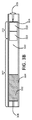
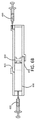
したがって、図1に示されるように、薬物を装填する準備ができている実施形態では、デバイス102は、流体を放出するための放出構造108を有する第1の端部、及び反対側の第2の端部を有する細長い管106を備えたハウジング104を含む。細長い管106は、流体薬物又はその前駆体を受容するように構成される。ハウジング104は、細長い管106の第2の端部に接続され、浸透圧剤110が配置される貯蔵部114も画定する。ハウジング104は、水が貯蔵部114に入り、浸透圧剤110と接触することを可能にするための透水性壁112を含む。デバイス102は、流体又はその前駆体を受容したときに、ピストンが流体と浸透圧剤110との間に形成されたガスを含むように構成される。デバイスは、透水性壁112を介して貯蔵部114内に水を吸収し、浸透圧剤によって発生した浸透圧を介して細長い管106を通してガスピストンを前進させて、放出構造108を介してデバイスから流体を送るように構成される。
Thus, as shown in FIG. 1, in an embodiment ready to be loaded with a drug, the
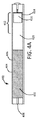
図4A〜図4Bに示される流体を予め装填した実施形態では、デバイス402は、流体432を放出するための放出構造408を有する第1の端部、及び反対側の第2の端部を有する細長い管406を備えたハウジング404を含む。ハウジング404は、細長い管406の第2の端部に接続され、浸透圧剤410が配置される貯蔵部414をさらに画定する。ハウジングは、水が貯蔵部に入り、浸透圧剤と接触することを可能にするための透水性壁412を含む。図4Bに示されるように、ガスピストン420は、浸透圧剤410によって発生した浸透圧下で、細長い管406の第1の端部に向かって細長い管406の管腔内を前進して、放出構造408を介して流体432を管腔の外に排出させるように動作可能である。
In the pre-loaded embodiment shown in FIGS. 4A-4B,
図4A〜図4Bに示されるように、これらの実施形態では、デバイスは、ピストン420を前進させて、デバイス402から薬物含有流体432を送る浸透圧がデバイス内で生じるように、透水性壁412を介して水411を吸収するように構成される。例えば、デバイスは、水性体液が存在する身体の内腔などの部位で患者に挿入又は移植するために構成され得る。例えば、デバイスは、流体薬物製剤の放出をもたらすために、尿がデバイス内に吸収され得る膀胱内に挿入するために構成され得る。
As shown in FIGS. 4A-4B, in these embodiments, the device is
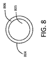
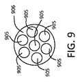
図8に示されるように、ある特定の実施形態では、ハウジング804は、単一の中心管腔805を有する環状管806を備える。別の実施形態では、細長い管906は、図9に示される、複数の管腔905を含む。各管腔は、流体薬物製剤又はその前駆体(例えば薬物の溶剤)を受容するように構成されるか、又はそれで装填され得る。
As shown in FIG. 8, in certain embodiments, the
図1に示されるように、ある特定の実施形態では、貯蔵部114は、流体を含むか、又はそれを受容するように構成される細長い管106と一体形成された環状管113によって形成又は画定される。一実施形態では、ハウジングは、第1のコンパートメント(例えば薬物流体含有コンパートメント)、及び第2のコンパートメント(例えば浸透圧剤含有コンパートメント)を画定する単一管を有する。
As shown in FIG. 1, in certain embodiments, the
他の実施形態では、貯蔵部は、流体を含むか、又はそれを受容するように構成される細長い管に接続される環状管によって形成される。一実施形態では、デバイスは、細長い管と貯蔵部とを接続するコネクタを含む。例えば、コネクタは、スペーサー開口部、弁、又は他の好適な接続機構であり得る。例えば、コネクタは、とげ付きのポリプロピレン取付具であり得る。 In other embodiments, the reservoir is formed by an annular tube connected to an elongate tube that contains or is configured to receive a fluid. In one embodiment, the device includes a connector that connects the elongated tube and the reservoir. For example, the connector can be a spacer opening, a valve, or other suitable connection mechanism. For example, the connector can be a barbed polypropylene fitting.
図3A〜図3Cに示されるように、細長い管304に流体又は前駆体332を受容したときに、ガスピストン320(空気の小塊又は泡)が流体332と浸透圧剤310との間に形成される。ガスピストン320は、浸透圧剤310と流体薬物製剤332との間に介在し、浸透圧剤310によって発生した浸透圧下で、放出構造308(即ち、細長い管の第1の端部)に向かって前進して、放出機構を介して流体薬物製剤332をデバイスの外に排出させるように動作可能である。
As shown in FIGS. 3A-3C, a gas piston 320 (air blob or bubble) forms between the fluid 332 and the
一実施形態では、細長い管の壁及び/又は貯蔵部の壁は、50ショアA〜90ショアAの範囲の硬さを有するエラストマーポリマーなどのポリマーから形成される。例えば、ポリマーは、シリコーン又はポリウレタンであり得る。一実施形態では、図3A〜図3Cに示されるように、細長い管304の壁307は、水不透過性である。ある特定の実施形態では、透水性部分312以外の貯蔵部314の壁の一部分307も水不透過性である。一実施形態では、細長い管の壁及び/又は貯蔵部の壁も空気不透過性である。例えば、細長い管及び/又は貯蔵部は、実質的に水及びガス不透過性のエラストマーポリマーで少なくとも部分的に形成されるか、又は実質的に水及びガス不透過性のコーティングを有し得る。例えば、細長い管の壁及び/又は貯蔵部の壁は、パリレンコーティングされたシリコーンから形成され得る。一実施形態では、パリレンは、パリレンCである。
In one embodiment, the wall of the elongated tube and / or the reservoir wall is formed from a polymer such as an elastomeric polymer having a hardness in the range of 50 Shore A to 90 Shore A. For example, the polymer can be silicone or polyurethane. In one embodiment, as shown in FIGS. 3A-3C, the
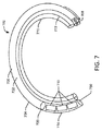
一実施形態では、浸透圧剤を含有する貯蔵部又はハウジングは、透水性管である。例えば、図1に示されるように、貯蔵部114は、透水性の壁領域112を有する管であり得る。別の実施形態では、図6A〜図6Cに示されるように、貯蔵部614の壁の透水性部分は、貯蔵部614の一端に透水性膜650を含む。例えば、図7に示されるように、貯蔵部714は、管状であってよく、管の端部に透水性ディスク750を含む。例えば、貯蔵部の壁の透水性部分は、親水性ポリマー、Tecophilic(登録商標)(Lubrizol Advanced Materials,Inc.)、HydroThane(商標)(AdvanSource Biomaterials)、Quadraphilic(商標)(Biomerics)などの熱可塑性ポリウレタン、又は親水性Pebax(登録商標)MV 1074 SA 01 MED(Arkema)などの親水性ポリエーテルブロックアミドコポリマーを含み得る。
In one embodiment, the reservoir or housing containing the osmotic agent is a water permeable tube. For example, as shown in FIG. 1, the
一実施形態では、流体を含有又は受容する細長い管は、毛管力が管内で重力より優勢であるように寸法決定された内径を有する。つまり、管は、流体薬物製剤が実質的に重力の補助なく分注端部に向かって管を貫流することが可能であるように寸法決定及び成形され得る。単一管腔管及び複数管腔管の断面図は、それぞれ、図8及び9に示される。複数管腔管の総開口面積が単一管腔管と同じ場合、流体薬物製剤、流体ピストン、及び浸透圧溶液を確実に分離させるために複数管腔管が好ましい場合がある。各個々の管腔の内径は、毛管力が浮力又は重力より優勢であり得るように十分に小さくなくてはならない。次に、圧縮空気小塊は、流体薬物製剤と分離されたままであり、浸透圧流入によって支持されたピストン又はプランジャとして作用し得る。図8と比較して、図9の管は、流体製剤の通路として機能し得る複数の小さい毛管路(即ち、管腔)905を有する。 In one embodiment, the elongate tube containing or receiving fluid has an inner diameter dimensioned such that capillary forces prevail over gravity within the tube. That is, the tube can be sized and shaped so that the fluid drug formulation can flow through the tube toward the dispensing end with substantially no gravity assistance. Cross-sectional views of a single lumen tube and a multiple lumen tube are shown in FIGS. 8 and 9, respectively. If the total open area of the multiple lumen tube is the same as the single lumen tube, the multiple lumen tube may be preferred to ensure separation of the fluid drug formulation, the fluid piston, and the osmotic solution. The inner diameter of each individual lumen must be small enough so that capillary forces can prevail over buoyancy or gravity. The compressed air blob can then remain separated from the fluid drug formulation and act as a piston or plunger supported by osmotic inflow. Compared to FIG. 8, the tube of FIG. 9 has a plurality of small capillary channels (ie, lumens) 905 that can serve as fluid formulation passages.
毛管力が浮力/重力より優勢であるために、ボンド数に基づき寸法分析を行うことができ、これは、
![]()
![]()
![]()
![]()
![]()
![]()
一実施形態では、細長い管及び貯蔵部は、約1mm〜約3mmの内径を有するシリコーン管から形成される。例えば、ハウジングは、1mm〜3mmの直径を有する中心管腔を有し得る。 In one embodiment, the elongated tube and reservoir are formed from a silicone tube having an inner diameter of about 1 mm to about 3 mm. For example, the housing may have a central lumen having a diameter of 1 mm to 3 mm.
一実施形態では、図3A〜図3Cに示されるように、デバイスは、細長い管又は貯蔵部314(貯蔵部314と連通して図示される)と流体連通している空気孔315も含む。空気孔315は、細長い管が流体又は前駆体332を受容した時点で、プラグ316などで塞がれるように構成される。図3Aに示されるように、流体の充填中、空気孔315は、流体が充填後に排出されないように(ガスピストンにより)開いたままであってよい。空気孔315は、この実施形態では1つ以上の浸透圧錠剤310の後ろに位置付けられ得るため、錠剤(複数可)314は、貯蔵部314に封止部を作製するのを避け、それによって、空気が充填中に空気孔315に向かって錠剤(複数可)310の周囲に流れるのを可能にするように寸法決定及び成形されるべきである。
In one embodiment, as shown in FIGS. 3A-3C, the device also includes an
代替の実施形態では、空気孔は、一時的に画定され、プラグが省かれる。つまり、端部のプラグは、中空の針が挿入され、空気が充填プロセス中に通気され得る通路を提供し、充填後、中空の針が引き出され、弾性材料が中空の針によって作製された穴を自己封止することを可能にし得る弾性材料から形成され得る。このようにして、プラグは必要ない。 In an alternative embodiment, the air holes are temporarily defined and the plug is omitted. That is, the plug at the end provides a passage through which a hollow needle can be inserted and air can be vented during the filling process, and after filling, the hollow needle is withdrawn and the elastic material is made by a hollow needle. May be formed from an elastic material that may allow the self-sealing. In this way, no plug is necessary.
一実施形態では、流体放出構造は、開口部及び/又は逆止弁を含む。例えば、逆止弁は、デバイスの外側から内側への毛細管又は不要な逆拡散を防止し得る。例えば、図3Aに示されるように、デバイスは、シリンジ334などの放出構造308を介して流体又は前駆体332を受容するように構成され得る。
In one embodiment, the fluid discharge structure includes an opening and / or a check valve. For example, a check valve may prevent capillaries or unwanted back diffusion from the outside to the inside of the device. For example, as shown in FIG. 3A, the device may be configured to receive a fluid or
図12に示されるように、一実施形態では、デバイスは、流体薬物製剤1232で装填され、スペーサー開口部コネクタ1282によって接続された2つのコンパートメント1206を含む。
As shown in FIG. 12, in one embodiment, the device includes two
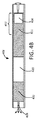
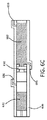
一実施形態では、図6A〜図6Cに示されるように、デバイスは、貯蔵部614に隣接し、貯蔵部の壁の透水性部分650を介して貯蔵部内に吸収される水660を収容するように構成されたコンパートメント652も含む。例えば、搭載された水コンパートメントを有するデバイスは、患者の子宮など、薬物送達のための水が少ない組織部位での使用に好適であり得る。
In one embodiment, as shown in FIGS. 6A-6C, the device is adjacent to the
ある特定の実施形態では、図6A〜図6Cに示されるように、貯蔵部614の透水性壁650は、貯蔵部614とコンパートメント652との間に位置付けられる親水性膜を含む。一実施形態では、デバイスは、コンパートメント652と流体連通している空気孔654をさらに含む。この実施形態では、コンパートメントが水660を受容した時点で、空気孔は、プラグ655などで塞がれるように構成される。コンパートメントは、水660をコンパートメント内に導入することができるポート656も含み得る。ポート656は、水がコンパートメント652から浸透圧貯蔵部614内に引き込まれる間、コンパートメント652が崩壊しないように、開かれたままであってよい。別の実施形態では、コンパートメントの壁は、薄いプラスチックフィルムなどの折り畳み可能な材料から作製することができるため、水がコンパートメントから浸透圧貯蔵部内に引き込まれる間、壁は、容易に崩壊することができる。この場合、コンパートメントの任意のポートは、水を受容するときに閉められる。
In certain embodiments, as shown in FIGS. 6A-6C, the
図6A〜図6Cに示されるように、ある特定の実施形態では、デバイスは、細長い管606又は貯蔵部614と流体連通している空気孔615も含む。空気孔615は、細長い管606が流体又は前駆体632を受容した時点で、プラグ616などで塞がれるように構成される。図6Bに示されるように、流体の充填中、空気孔615は、流体が充填後に排出されないように(ガスピストンにより)開いたままであってよい。
As shown in FIGS. 6A-6C, in certain embodiments, the device also includes an air hole 615 in fluid communication with the
一実施形態では、デバイスは、薬物溶液を収容するための第1のコンパートメント、浸透圧剤を収容する第2のコンパートメント、及び同様に流体を受容し、放出するためのコンパートメントを含む。例えば、デバイスは、デバイスの中心に浸透圧領域及びそれに隣接した複数の空気小塊/薬物コンパートメントを有する2重放出設計を有し得る。 In one embodiment, the device includes a first compartment for containing a drug solution, a second compartment for containing an osmotic agent, and a compartment for receiving and releasing fluid as well. For example, the device may have a dual release design with an osmotic region in the center of the device and a plurality of air blob / drug compartments adjacent to it.
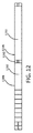
一実施形態では、図7に示されるように、薬物送達デバイス702は、(i)液体薬物製剤732で装填された管腔を有する細長い可撓性管706であって、(a)液体薬物製剤732を放出するための分注開口部708を有する第1の端部、及び(b)反対側の第2の端部を有する管、(ii)細長い管706の第2の端部に接続され、浸透圧剤710が配置される貯蔵部を画定するハウジング部分714であって、水が貯蔵部に入り、かつ浸透圧剤710と接触することを可能にするための透水性壁750を有する、ハウジング部分、並びに(iii)浸透圧剤710と液体薬物製剤732との間に介在する管腔中に流体ピストン720を含み、該流体ピストン720は、浸透圧剤710によって発生した浸透圧下で、第1の端部に向かって管腔内を前進して、分注開口部708を介して液体薬物製剤732を管腔の外に排出させる(矢印の方向に)ように動作可能である。使用中、水は壁750を通して吸収され、管腔に入り、浸透圧剤710を可溶化し、浸透圧溶液を形成する。水は吸収され続け、浸透圧を作り出し、これは、流体ピストン720の排出によって解放される。
In one embodiment, as shown in FIG. 7,
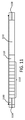
デバイス702は、保持フレーム772が固定される保持フレーム管腔770をさらに含む。図7に示されるように、弾性ワイヤ(例えば、ニチノールなどの超弾性合金)を備え得る保持フレームは、コイル形状をデバイスに付与する。図示される実施形態では、保持フレームは、圧縮荷重の不在下で、医療デバイスを、コイルを有する形状にさせる。例えば、この形状は、圧縮荷重が患者の尿道の管腔を通したデバイスの挿入に好適であろう示される真っ直ぐな形状に医療デバイスを維持する、図11に示されるデバイスの実施形態とは対照的に、患者の膀胱内でのデバイスの保持に好適であろう。
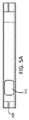
一実施形態では、図1に示されるように、細長い管内に装填される流体は、薬物の溶液である、即ち、放出される流体薬物製剤である。別の実施形態では、図5A〜図5Cに示されるように、薬物531の固体又は半固体製剤は細長い管内に収容され、細長い部分内に装填される流体533は、細長い管内に流体前駆体を受容したときに、溶剤が薬物を溶解して、デバイスから放出される流体薬物製剤を形成するような、流体薬物製剤の前駆体(例えば薬物製剤の溶剤)である。例えば、薬物は、粉末又は1つ以上の錠剤、カプセル、もしくはペレットの形態であってよい。溶剤は、例えば、水、ジメチルスルホキシド(DMSO)、及び/又はジメチルホルムアミド(DMF)であり得る。特定の実施形態では、DMSOは、間質性膀胱炎と呼ばれる膀胱状態の症状を緩和するための膀胱内薬剤としての使用が既に知られているため、好ましい溶剤であり得る。
In one embodiment, as shown in FIG. 1, the fluid loaded into the elongate tube is a solution of drug, ie, a fluid drug formulation that is released. In another embodiment, as shown in FIGS. 5A-5C, a solid or semi-solid formulation of
本明細書において使用される、用語「薬物」は、任意の好適な薬学的に活性な成分を包含する。薬物は、他の形態/種類の活性成分の中でも、小分子、巨大分子、生物学的製剤、又は代謝物であり得る。本明細書に記載の薬物は、塩形態、遊離酸形態、有機塩基形態、及び水和物などのその代替形態を含む。薬物は、当該技術分野において既知の1つ以上の薬学的に許容される賦形剤と共に製剤化され得る。薬物の非限定的な例は、ゲムシタビン、オキサリプラチン、及び/もしくは別の化学療法剤、オキシブチニン、トロスピウム、及び/もしくは別の抗ムスカリン剤、並びに/又はリドカイン、及び/もしくは別の麻酔剤を含む。一実施形態では、第1のコンパートメント(例えば細長い管)は、薬物の組み合わせが送達されるように、2つ以上の種類の薬物錠剤(例えば異なる薬物)で装填され得る。 As used herein, the term “drug” includes any suitable pharmaceutically active ingredient. The drug can be a small molecule, macromolecule, biologic, or metabolite, among other forms / types of active ingredients. The drugs described herein include salt forms, free acid forms, organic base forms, and alternative forms thereof such as hydrates. The drug can be formulated with one or more pharmaceutically acceptable excipients known in the art. Non-limiting examples of drugs include gemcitabine, oxaliplatin, and / or another chemotherapeutic agent, oxybutynin, trospium, and / or another antimuscarinic agent, and / or lidocaine, and / or another anesthetic agent . In one embodiment, the first compartment (eg, elongate tube) can be loaded with more than one type of drug tablet (eg, different drugs) such that a combination of drugs is delivered.
いくつかの実施形態では、薬物は、疼通を治療するために使用されるものである。様々な麻酔剤、鎮痛剤、及びこれらの組み合わせが使用され得る。一実施形態では、薬物は麻酔剤である。麻酔剤は、コカイン類似体であり得る。麻酔剤は、アミノアミド、アミノエステル、又はこれらの組み合わせであり得る。アミノアミド又はアミドクラスの麻酔剤の代表的な例としては、アルチカイン、ブピバカイン、カルチカイン、シンコカイン、エチドカイン、レボブピバカイン、リドカイン、メピバカイン、プリロカルン(prilocalne)、ロピバカイン、及びトリメカインが挙げられる。アミノエステル又はエステルクラスの麻酔剤の代表的な例としては、アミロカルン(amylocalne)、ベンゾカイン、ブタカイン、クロロプロカイン、コカイン、シクロメチカイン、ジメトカイン、ヘキシルカイン、ラロカイン、メプリルカイン、メタブトキシカイン、オルトカイン、ピペロカイン、プロカイン、プロパラカイン、プロポキシカイン、プロキシメタカイン、リソカイン、及びテトラカインが挙げられる。薬物はまた、オキシブチニン又はプロピベリンなどの麻酔作用を呈する抗ムスカリン化合物であってもよい。複数の実施形態では、鎮痛剤はオピオイドを含む。オピオイド作動薬の代表的な例としては、アルフェンタニル、アリルプロジン、アルファプロジン、アニレリジン、ベンジルモルヒネ、ベジトラミド、ブプレノルフィン、ブトルファノール、クロニタゼン、コデイン、デソモルヒネ、デキストロモラミド、デゾシン、ジアンプロミド、ジアモルフォン、ジヒドロコデイン、ジヒドロモルヒネ、ジメノキサドール(dimenoxadol)、ジメフェプタノール、ジメチルチアムブテン、ジオキサフェチルブチレート、ジピパノン、エプタゾシン、エトヘプタジン、エチルメチルチアムブテン、エチルモルヒネ、エトニタゼンフェンタニール、ヘロイン、ヒドロコドン、ヒドロモルフォン、ヒドロキシペチジン、イソメタドン、ケトベミドン、レボルファノール、レボフェナシルモルファン、ロフェンタニル、メペリジン、メプタジノール、メタゾシン、メタドン、メトポン、モルヒネ、ミロフィン、ナルブフィン、ナルセイン、ニコモルヒネ、ノルレボルファノール、ノルメタドン、ナロルフィン、ノルモルヒネ、ノルピパノン、アヘン、オキシコドン、オキシモルフォン、パパベレタム(papavereturn)、ペンタゾシン、フェナドキソン、フェノモルファン、フェナゾシン、フェノペリジン、ピミノジン、ピリトラミド、プロヘプタジン、プロメドール、プロペリジン、プロピラム、プロポキシフェン、スフェンタニル、チリジン、トラマドール、これらの薬学的に許容される塩、及びこれらの混合物が挙げられる。ミュー、カッパ、デルタ、及び他の痛覚オピオイド受容体作動薬などの他のオピオイド薬物が想定される。他の好適な疼通緩和剤の代表的な例としては、サリチルアルコール、フェナゾピリジン塩酸塩、アセトアミノフェン、アセチルサリチル酸、フルフェニサール、イブプロフェン、インドプロフェン、インドメタシン、ナプロキセンなどの薬剤が挙げられる。 In some embodiments, the drug is one used to treat pain. A variety of anesthetics, analgesics, and combinations thereof can be used. In one embodiment, the drug is an anesthetic. The anesthetic agent can be a cocaine analog. The anesthetic agent can be an aminoamide, an aminoester, or a combination thereof. Representative examples of aminoamide or amide class anesthetics include articaine, bupivacaine, calcicaine, cinchocaine, etidocaine, levobupivacaine, lidocaine, mepivacaine, prilocalne, ropivacaine, and trimecaine. Representative examples of aminoester or ester class anesthetics include amylocaln, benzocaine, butacaine, chloroprocaine, cocaine, cyclomethicaine, dimethocaine, hexylcaine, larocaine, meprilucaine, metabutoxycaine, orthocaine, piperocaine , Procaine, proparacaine, propoxycaine, proxymetacaine, lysokine, and tetracaine. The drug may also be an antimuscarinic compound that exhibits anesthetic action such as oxybutynin or propiverine. In embodiments, the analgesic comprises an opioid. Representative examples of opioid agonists include alfentanil, allylprozin, alphaprozin, anilellidine, benzylmorphine, vegitramide, buprenorphine, butorphanol, clonitazene, codeine, desomorphine, dextromoramide, dezocine, dianpromide, diamorphone, dihydrocodeine, Dihydromorphine, dimenoxadol, dimefeptanol, dimethylthiambutene, dioxafetylbutyrate, dipipanone, eptazocine, etoheptadine, ethylmethylthiambutene, ethylmorphine, etonitazenfentanil, heroin, hydrocodone, hydromorphone , Hydroxypetidin, isomethadone, ketobemidone, levorphanol, levofenacil morphane Lofentanil, meperidine, meptazinol, metazocine, methadone, methopone, morphine, mylofin, nalbuphine, narcein, nicomorphine, norlevorphanol, normethadone, nalolphine, normorphine, norpipanone, opium, oxycodone, oxymorphone, papaverpeturson, papaverzotson , Phenomorphan, phenazosin, phenoperidine, pimidine, pyritramide, proheptadine, promedol, properidine, propyram, propoxyphene, sufentanil, tyridine, tramadol, pharmaceutically acceptable salts thereof, and mixtures thereof. Other opioid drugs are envisioned, such as mu, kappa, delta, and other nociceptive opioid receptor agonists. Representative examples of other suitable pain relieving agents include drugs such as salicyl alcohol, phenazopyridine hydrochloride, acetaminophen, acetylsalicylic acid, flufenisal, ibuprofen, indoprofen, indomethacin, naproxen. It is done.
いくつかの実施形態では、薬物は、間質性膀胱炎、放射線膀胱炎、有痛性膀胱症候群、前立腺炎、尿道炎、術後痛、及び腎結石、などの炎症性状態を治療するために使用されるものである。これらの状態用の薬物の非限定的な例としては、リドカイン、グリコサミノグルカン(例えば、硫酸コンドロイチン、スロデキシド)、ペントサンポリ硫酸ナトリウム(PPS)、ジメチルスルホキシド(DMSO)、オキシブチニン、マイトマイシンC、ヘパリン、フラボキサート、ケトロラク、又はこれらの組み合わせが挙げられる。ICの治療に使用され得る薬物の他の非限定的な例としては、タネズマブ及びカルシウムチャネルアルファ−2−デルタ調節剤(PD−299685又はガベペンチンなど)などの神経成長因子モノクローナル抗体(MAB)拮抗薬が挙げられる。 In some embodiments, the drug is for treating inflammatory conditions such as interstitial cystitis, radiation cystitis, painful bladder syndrome, prostatitis, urethritis, postoperative pain, and kidney stones It is what is used. Non-limiting examples of drugs for these conditions include lidocaine, glycosaminoglucan (eg chondroitin sulfate, sulodexide), sodium pentosan polysulfate (PPS), dimethyl sulfoxide (DMSO), oxybutynin, mitomycin C, heparin , Flavoxate, ketorolac, or combinations thereof. Other non-limiting examples of drugs that can be used in the treatment of IC include nerve growth factor monoclonal antibody (MAB) antagonists such as tanezumab and calcium channel alpha-2-delta modulators (such as PD-299985 or gavepentin) Is mentioned.
いくつかの実施形態では、薬物は、切迫性失禁及び神経因性失禁、並びに膀胱三角部炎を含む、頻繁な又は切迫性の尿失禁を治療するために使用されるものである。使用され得る薬物は、抗コリン薬、鎮痙薬、抗ムスカリン剤、β−2作動薬、アルファアドレナリン作動薬、抗痙攣薬、ノルエピネフィリン取り込み阻害剤、セロトニン取り込み阻害剤、カルシウムチャネル遮断剤、カリウムチャネル開口薬、及び筋弛緩薬を含む。失禁を治療するための好適な薬剤の代表的な例としては、オキシブチニン、S−オキシブチリン、エメプロニウム、ベラパミル、イミプラミン、フラボキサート、アトロピン、プロパンテリン、トルテロジン、ロシベリン、クレンブテロール、ダリフェナシン、テロジリン、トロスピウム、ヒヨスチアミン、プロピベリン、デスモプレシン、バミカミド、臭化クリジニウム、ジサイクロミンHCl、グリコピロレートアミノアルコールエステル、臭化イプラトロピウム、臭化メペンゾラート、臭化メトスコポラミン、臭化水素酸スコポラミン、臭化イオトロピウム、フマル酸フェソテロジン、YM−46303(Yamanouchi Co.,Japan)、ランペリゾン(Nippon Kayaku Co.,Japan)、イナペリソン、NS−21(Nippon Shinyaku Orion,Formenti,Japan/Italy)、NC−1800(Nippon Chemiphar Co.,Japan)、Z D−6169(Zeneca Co.,United Kingdom)、及びヨウ化スチロニウムが挙げられる。 In some embodiments, the drug is one used to treat frequent or urge urinary incontinence, including urge and neurogenic incontinence, and cystitis. Drugs that can be used include anticholinergic drugs, antispasmodics, antimuscarinic drugs, beta-2 agonists, alpha adrenergic drugs, anticonvulsants, norepinephrine uptake inhibitors, serotonin uptake inhibitors, calcium channel blockers, Includes potassium channel openers and muscle relaxants. Representative examples of suitable agents for treating incontinence include oxybutynin, S-oxybutyrin, emepronium, verapamil, imipramine, flavoxate, atropine, propantheline, tolterodine, rosiverine, clenbuterol, darifenacin, terodiline, trospium, hyoscyamine , Propiverine, desmopressin, bamicamide, clidinium bromide, dicyclomine HCl, glycopyrrolate amino alcohol ester, ipratropium bromide, mepenzolate bromide, methoscopolamine bromide, scopolamine hydrobromide, itropium bromide, fesoterodine fumarate, YM- 46303 (Yamanouchi Co., Japan), Lamperisone (Nippon Kayaku Co., Japan), Inaperiso , NS-21 (Nippon Shinyaku Orion, Formenti, Japan / Italy), NC-1800 (Nippon Chemiphar Co., Japan), Z D-6169 (Zeneca Co., United Kingdom), and include iodide Suchironiumu.
いくつかの実施形態では、薬物は、膀胱癌及び前立腺癌などの尿路癌を治療するために使用されるものである。使用され得る薬物は、抗増殖性薬剤、細胞毒性薬剤、化学療法剤、又はこれらの組み合わせを含む。尿路癌の治療に好適であり得る薬物の代表的な例としては、カルメット−ゲラン桿菌(BCG)ワクチン、シスプラチン、ドキソルビシン、バルルビシン、ゲムシタビン、マイコバクテリア細胞壁−DNA複合体(MCC)、メトトレキサート、ビンブラスチン、チオテパ、マイトマイシン、フルオロウラシル、ロイプロリド、ジエチルスチルベストロール、エストラムスチン、酢酸メゲストール、シプロテロン、フルタミド、選択的エストロゲン受容体調節剤(即ち、タモキシフェンなどのSERM)、ボツリヌス毒素、及びシクロホスファミドが挙げられる。薬物は、生物学的製剤であってよく、モノクローナル抗体、TNF阻害剤、抗ロイキンなどを含み得る。薬物はまた、TLR作動薬(イミキモド又は別のTLR7作動薬を含む)などの免疫調節剤であってもよい。薬物は、特に線維芽細胞成長因子受容体−3(FGFR3)−選択的チロシンキナーゼ阻害剤、ホスファチジルイノシトール3キナーゼ(PI3K)阻害剤、又はマイトジェン活性化タンパク質キナーゼ(MAPK)阻害剤、又はこれらの組み合わせなどのキナーゼ阻害剤であってもよい。他の例は、セレコキシブ、エロロチニブ、ゲフィチニブ、パクリタキセル、ポリフェノンE、バルルビシン、ネオカルジノスタチン、アパジコン(apaziquone)、ベリノスタット、インゲノールメブテート、Urocidin(MCC)、Proxinium(VB 4845)、BC 819(BioCancell Therapeutics)、キーホールリンペットヘモシアニン、LOR 2040(Lorus Therapeutics)、ウロカニン酸、OGX 427(OncoGenex)、及びSCH 721015(Schering−Plough)を含む。他の膀胱内癌治療は、小分子(アパジコン、アドリアマイシン、AD−32、ドキソルビシン、ドセタキセル、エピルビシン、ゲムシタビン、HTI−286(ヘミアステリン類似体)、イダルビシン、γ−リノレン酸、ミトザントロン、メグルミン、及びチオテパなど)、巨大分子(活性化マクロファージ、活性化T細胞、EGF−デキストラン、HPC−ドキソルビシン、IL−12、IFN−a2b、IFN−γ、α−ラクトアルブミン、p53アデノベクター、TNFαなど)、組み合わせ(エピルビシン+BCG、IFN+ファルマルビシン(farmarubicin)、ドキソルビシン+5−FU(経口)、BCG+IFN、及び百日咳毒素+嚢胞切除)、活性化細胞(マクロファージ及びT細胞など)、膀胱内注入(IL−2及びドキソルビシンなど)、化学増感剤(BCG+抗線溶薬(antifirinolytics)(パラメチル安息香酸又はアミノカプロン酸など)及びドキソルビシン+ベラピミルなど)、診断剤/造影剤(ヘキサアミノレブリン酸塩、5−アミノレブリン酸、ヨードデキシウリジン(Iododexyuridine)、HMFG1 Mab+Tc99mなど)、並びにホルマリン(出血性膀胱炎)などの局所毒性を管理するための薬剤を含む。 In some embodiments, the drug is one used to treat urinary tract cancers such as bladder cancer and prostate cancer. Drugs that can be used include antiproliferative agents, cytotoxic agents, chemotherapeutic agents, or combinations thereof. Representative examples of drugs that may be suitable for the treatment of urinary tract cancer include: Calmet-Guerin bacilli (BCG) vaccine, cisplatin, doxorubicin, valrubicin, gemcitabine, mycobacterial cell wall-DNA complex (MCC), methotrexate, vinblastine Thiotepa, mitomycin, fluorouracil, leuprolide, diethylstilbestrol, estramustine, megestol acetate, cyproterone, flutamide, selective estrogen receptor modulators (ie, SERMs such as tamoxifen), botulinum toxin, and cyclophosphamide Can be mentioned. The drug can be a biologic and can include monoclonal antibodies, TNF inhibitors, anti-leukins, and the like. The drug may also be an immunomodulator such as a TLR agonist (including imiquimod or another TLR7 agonist). The drug is in particular a fibroblast growth factor receptor-3 (FGFR3) -selective tyrosine kinase inhibitor, a phosphatidylinositol 3 kinase (PI3K) inhibitor, or a mitogen activated protein kinase (MAPK) inhibitor, or a combination thereof Kinase inhibitors such as Other examples are celecoxib, erlotinib, gefitinib, paclitaxel, polyphenone E, valrubicin, neocarzinostatin, apadicon, verinostat, ingenol mebutate, Urocidin (MCC), Proxinium (VB 4845), C BioCancell Therapeutics), keyhole limpet hemocyanin, LOR 2040 (Lorus Therapeutics), urocanic acid, OGX 427 (OncoGenex), and SCH 721015 (Schering-Plough). Other intravesical cancer treatments include small molecules (apadicon, adriamycin, AD-32, doxorubicin, docetaxel, epirubicin, gemcitabine, HTI-286 (hemiasterin analog), idarubicin, γ-linolenic acid, mitozantrone, meglumine, thiotepa, etc. ), Macromolecules (activated macrophages, activated T cells, EGF-dextran, HPC-doxorubicin, IL-12, IFN-a2b, IFN-γ, α-lactalbumin, p53 adenovector, TNFα, etc.), combinations (epirubicin) + BCG, IFN + farmarubicin, doxorubicin + 5-FU (oral), BCG + IFN, and pertussis toxin + cystectomy), activated cells (such as macrophages and T cells), intravesical infusion (IL-2 And doxorubicin), chemical sensitizers (BCG + antifibrinolytics (such as paramethylbenzoic acid or aminocaproic acid) and doxorubicin + verapimil), diagnostic / contrast agents (hexaaminolevulinate, 5-aminolevulinic acid, Includes drugs for managing local toxicity such as iododexuridine, such as HMFG1 Mab + Tc99m, and formalin (hemorrhagic cystitis).
いくつかの実施形態では、薬物は、膀胱、前立腺、及び尿道に関する感染を治療するために使用されるものである。抗生物質、抗菌剤、抗真菌剤、抗原虫薬、消毒剤、抗ウイルス剤、及び他の抗感染剤がそのような感染を治療するために投与され得る。感染を治療するための薬剤の代表的な例としては、マイトマイシン、シプロフロキサシン、ノルフロキサシン、オフロキサシン、メタンアミン、ニトロフラントイン、アンピシリン、アモキシリン、ナフシリン、トリメトプリム、スルホンアミド、トリメトプリムスルファメトキサゾール、エリスロマイシン、ドキシサイクリン、メトロニダゾール、テトラサイクリン、カナマイシン、ペニシリン、セファロスポリン、及びアミノグリコシドが挙げられる。 In some embodiments, the drug is one used to treat infections involving the bladder, prostate, and urethra. Antibiotics, antibacterial agents, antifungal agents, antiprotozoal agents, disinfectants, antiviral agents, and other anti-infective agents can be administered to treat such infections. Representative examples of drugs for treating infection include mitomycin, ciprofloxacin, norfloxacin, ofloxacin, methanamine, nitrofurantoin, ampicillin, amoxiline, naphthylline, trimethoprim, sulfonamide, trimethoprimsulfamethoxazole, Examples include erythromycin, doxycycline, metronidazole, tetracycline, kanamycin, penicillin, cephalosporin, and aminoglycosides.
いくつかの実施形態では、薬物は、膀胱又は子宮などの泌尿生殖器部位の線維症を治療するために使用されるものである。筋腫を治療するための薬物の代表的な例としては、ペントクスフィリン(pentoxphylline)(キサンチン類似体)、抗TNF剤、抗TGF剤、GnRH類似体、外因性プロゲスチン、抗プロゲスチン、選択的エストロゲン受容体調節剤、ダナゾール、及びNSAIDが挙げられる。 In some embodiments, the drug is one used to treat fibrosis of urogenital sites such as the bladder or uterus. Representative examples of drugs for treating myoma include pentoxphyllin (xanthine analog), anti-TNF agent, anti-TGF agent, GnRH analog, exogenous progestin, antiprogestin, selective estrogen receptor Body regulators, danazol, and NSAIDs.
いくつかの実施形態では、薬物は、神経因性膀胱を治療するために使用されるものである。そのような薬物の代表的な例は、鎮痛剤又は麻酔剤(リドカイン、ブピバカイン、メピバカイン、プリロカルン(prilocalne)、アルチカイン、及びロピバカインなど)、抗コリン作用薬、抗ムスカリン剤(オキシブチニン又はプロピベリンなど)、バニロイド(カサプサイチン又はレシニフェラトキシンなど)、抗ムスカリン剤(M3ムスカリンアセチルコリン受容体(mAChR)に作用するもの)、鎮痙薬(バクロフェンなどのGABAB作動薬を含む)、ボツリヌス毒素、カサプサイチン、α−アドレナリン拮抗薬、抗痙攣薬、セロトニン取り込み阻害剤(アミトリプチリンなど)、及び神経成長因子拮抗薬が挙げられる。様々な実施形態では、薬物は、膀胱求心路に作用するもの、又はReitz et al.,Spinal Cord 42:267−72(2004)に記載の遠心路コリン性伝達に作用するものであり得る。 In some embodiments, the drug is one used to treat neurogenic bladder. Representative examples of such drugs are analgesics or anesthetics (such as lidocaine, bupivacaine, mepivacaine, prilocalne, articaine, and ropivacaine), anticholinergics, antimuscarinic agents (such as oxybutynin or propiverine), Vanilloids (such as casapsaitin or resiniferatoxin), antimuscarinic agents (acting on M3 muscarinic acetylcholine receptor (mAChR)), antispasmodic drugs (including GABA B agonists such as baclofen), botulinum toxin, casapsaitin, α- Adrenaline antagonists, anticonvulsants, serotonin uptake inhibitors (such as amitriptyline), and nerve growth factor antagonists. In various embodiments, the drug acts on the bladder afferent, or Reitz et al. , Spinal Cord 42: 267-72 (2004).
いくつかの実施形態では、薬物は、神経系排尿筋過活動及び/又はコンプライアンス排尿筋に起因する失禁を治療するために使用されるものである。これらの種類の薬物の例としては、膀胱弛緩薬(例えば、オキシブチニン(明白な筋弛緩活性及び局所麻酔活性を有する抗ムスカリン剤)、プロピベリン、インプラトロピウム(impratroprium)、チオトロピウム、トロスピウム、テロジリン、トルテロジン、プロパンテリン、オキシフェンサイクリミン、フラボキサート、及び三環系抗うつ薬、膀胱及び尿道を支配する神経を遮断する薬物(例えば、バニロイド(カプサイシン、レシニフェラトキシン)、ボツリヌス毒素A)、又は排尿筋収縮強度、排尿反射、排尿筋括約筋協調不全を調節する薬物(例えば、GABAb作動薬(バクロフェン)、ベンゾジアザピン)が挙げられる。別の実施形態では、神経系括約筋不全に起因する失禁の治療用として知られるものから選択される。これらの薬物の例としては、α−アドレナリン作動薬、エストロゲン、βアドレナリン作動薬、三環系抗うつ薬(イミプラミン、アミトリプチリン)が挙げられる。さらに別の実施形態では、薬物は、排尿を促進することが知られるものから選択される(例えば、α−アドレナリン拮抗薬(フェントラミン)又はコリン作動薬)。また別の実施形態では、薬物は、抗コリン作動薬(例えば、ジサイクロミン)、カルシウムチャネル遮断薬(例えば、ベラパミル)トロパンアルカロイド(例えば、アトロピン、スコポラミン)、ノシセプチン/オルファニンFQ、及びベタネコール(例えば、M3ムスカリン作動薬、コリンエステル)の中から選択される。 In some embodiments, the drug is one used to treat incontinence due to nervous detrusor overactivity and / or compliance detrusor. Examples of these types of drugs include bladder relaxants (eg, oxybutynin (an antimuscarinic agent with overt muscle relaxant activity and local anesthetic activity), propiverine, impratropium, tiotropium, trospium, terodiline, tolterodine , Propantheline, oxyphencyclimine, flavoxate, and tricyclic antidepressants, drugs that block the nerves that control the bladder and urethra (eg, vanilloid (capsaicin, resiniferatoxin), botulinum toxin A), or urination Drugs that modulate muscle contraction strength, micturition reflex, detrusor sphincter coordination dysfunction (eg, GABAb agonist (baclofen), benzodiazapine) In another embodiment, for the treatment of incontinence due to nervous system sphincter dysfunction Select from known Examples of these drugs include α-adrenergic drugs, estrogens, β-adrenergic drugs, tricyclic antidepressants (imipramine, amitriptyline) In yet another embodiment, the drug Selected from those known to promote (eg, α-adrenergic antagonists (phentolamine) or cholinergic agents) In yet another embodiment, the drug is an anticholinergic agent (eg, dicyclomine), calcium channel A blocker (eg, verapamil) tropane alkaloid (eg, atropine, scopolamine), nociceptin / orphanin FQ, and bethanechol (eg, M3 muscarinic agonist, choline ester).
浸透圧剤は、固体、半固体、又は溶液の形態であり得る。一実施形態では、浸透圧剤は、粉末、又は1つ以上の錠剤、カプセル、もしくはペレットの形態である。例えば、管状貯蔵部は、1つ以上の円筒形浸透圧剤の錠剤を収容し得る。浸透圧剤は、クエン酸一ナトリウム、クエン酸二ナトリウム、クエン酸三ナトリウム、ラクトース、塩化ナトリウム、尿素、スクロース、及びこれらの組み合わせからなる群から選択され得る。他の浸透圧剤も想定される。 The osmotic agent can be in the form of a solid, semi-solid, or solution. In one embodiment, the osmotic agent is in the form of a powder or one or more tablets, capsules or pellets. For example, the tubular reservoir may contain one or more cylindrical osmotic tablets. The osmotic agent may be selected from the group consisting of monosodium citrate, disodium citrate, trisodium citrate, lactose, sodium chloride, urea, sucrose, and combinations thereof. Other osmotic agents are also envisioned.
好ましい実施形態では、その例は図7に示され、デバイス702は、弾性的に変形可能である。例えば、デバイスは、患者の尿道を通した挿入に好適な第1の形状と患者の膀胱内でのデバイスの保持に好適な第2の形状との間で弾性的に変形可能であり得る。例えば、膀胱内に配備された後に保持形状にある場合、デバイスは有利に、排尿力又は他の力に応答する排泄を防止し得る。デバイスは管腔又は体腔内に保持されるように設計されるため、それらは、膀胱に関連するものなど、従来の治療に欠けているいくつかの部分を克服することが可能である。
In a preferred embodiment, an example is shown in FIG. 7, and the
本明細書に記載のデバイスは、一度挿入され、手術又は頻繁に介入をすることなく、所望の時間期間放出され得る。結果として、デバイスは、感染及び副作用の可能性を低減することができ、膀胱に局所的又は局部的に送達される薬物の量を増加させることができ、治療プロセス中の患者の生活の質を改善することができる。薬物放出が完了した後、デバイスは患者から除去される。除去は、例えばカテーテルもしくは膀胱鏡を用いて医師により、尿道を通して延在するデバイスに接続された回収糸を用いて退出させることにより、デバイスを体内で生分解もしくは生浸食させることにより、又はデバイス(又はその部品)が排尿中に排泄されるようにその保持形状を失うための手段を有するデバイスを提供することにより回収することを含む、いくつかの異なる方法によって達成することができる。これらの手段は、デバイスを部分的もしくは全体的に生浸食性材料で形成すること、及び/又は例えば閉じ込められたガスをデバイスから逃がすことによってデバイスに浮力を失わせることによることを含み得る。 The devices described herein can be inserted once and released for a desired period of time without surgery or frequent intervention. As a result, the device can reduce the likelihood of infection and side effects, increase the amount of drug delivered locally or locally to the bladder, and improve the patient's quality of life during the treatment process. Can be improved. After drug release is complete, the device is removed from the patient. Removal may be accomplished by a doctor using, for example, a catheter or cystoscope, withdrawing with a collection thread connected to a device extending through the urethra, by biodegrading or bioeroding the device in the body, or by a device ( Or a part thereof) can be achieved by a number of different methods, including recovery by providing a device having means for losing its retaining shape so that it is excreted during urination. These means may include forming the device partially or wholly of a bioerodible material and / or by causing the device to lose buoyancy, eg, by escaping trapped gas from the device.
一実施形態では、薬物送達デバイスは、自然に保持形状を取ることができ、手動で又は外部装置の補助のいずれかにより、身体内に挿入するための比較的真っ直ぐな形状に変形され得る。配備された時点で、デバイスは、自発的に又は自然に、身体内で保持するための初期保持形状に戻ることができる。本開示の目的のため、用語「保持形状」は、一般に、デバイスを膀胱内に保持するのに適したコイル又は「プレッツェル」形状を含むがこれらに限定されない、意図される移植位置にデバイスを保持するのに適した任意の形状を指す。同様に、用語「比較的真っ直ぐな形状」は、一般に、カテーテル、膀胱鏡、もしくは尿道などの身体の内腔に位置付けられる他の配備機器の作業チャネルを通してデバイスを配備するのに適した線形又は細長い形状を含むがこれらに限定されない、身体内に薬物送達デバイスを配備するのに適した任意の形状を指す。 In one embodiment, the drug delivery device can naturally take a retained shape and be deformed into a relatively straight shape for insertion into the body, either manually or with the aid of an external device. Once deployed, the device can spontaneously or spontaneously return to its initial holding shape for holding in the body. For purposes of this disclosure, the term “holding shape” generally holds the device in the intended implantation position, including but not limited to a coil or “pretzel” shape suitable for holding the device in the bladder. Refers to any shape suitable to do. Similarly, the term “relatively straight shape” is generally linear or elongated suitable for deploying a device through the working channel of a catheter, cystoscope, or other deployment instrument located in a body lumen such as the urethra. Refers to any shape suitable for deploying a drug delivery device within the body, including but not limited to a shape.
一実施形態では、薬物送達デバイスは、比較的真っ直ぐな形状と保持形状との間で弾性的に変形可能である保持フレームを必要としない。これらの実施形態では、ハウジングが形成される材料がデバイスが2つの形状間で弾性的に変形することを可能にさせる。別の実施形態では、薬物送達デバイスは、ハウジング704に関連する、例えば、図7などに示される保持フレーム772を収容する別個の管腔770に保持フレーム772を含む。保持フレームの特性は、デバイスをバネとして機能させ、圧縮荷重に応じて変形するが、荷重が取り除かれた時点で、自発的にその初期形状に戻る。一実施形態では、保持フレーム772は、図7に示されるように、ハウジング704と一体形成されるか、ないしは別の方法でそれに接続される保持フレーム管腔770に位置する。別の実施形態では、保持フレームは、接着剤などの好適な手段によってハウジングに固定される。
In one embodiment, the drug delivery device does not require a holding frame that is elastically deformable between a relatively straight shape and a holding shape. In these embodiments, the material from which the housing is formed allows the device to elastically deform between the two shapes. In another embodiment, the drug delivery device includes a
ある特定の実施形態では、デバイス自体と同様、保持フレームは、自然に保持形状を取ることができ、比較的真っ直ぐな形状に変形することができ、身体内に挿入されたときに自発的に保持形状に戻ることができる。保持形状の保持フレームは、体腔に保持するために成形され得、比較的真っ直ぐな形状の保持フレームは、カテーテル又は膀胱鏡などの配備機器の作業チャネルを通して身体内に挿入するために成形され得る。このような結果を得るために、保持フレームは、移植された時点で、デバイスが比較的低プロファイルの形状を取るのを防止するように選択された弾性限界、係数、及び/又はバネ定数を有し得る。そのような構成は、予想される力下でデバイスが身体から偶発的に排出されるのを制限又は防止し得る。例えば、デバイスは、排尿又は排尿筋の収縮中、膀胱内に保持され得る。 In certain embodiments, like the device itself, the holding frame can naturally take a holding shape, deform into a relatively straight shape, and hold spontaneously when inserted into the body. Return to shape. The retention shaped retention frame can be shaped for retention in a body cavity, and the relatively straight shaped retention frame can be shaped for insertion into the body through the working channel of a deployment device such as a catheter or cystoscope. To obtain such results, the retention frame has an elastic limit, modulus, and / or spring constant selected to prevent the device from taking a relatively low profile shape when implanted. Can do. Such a configuration may limit or prevent the device from being accidentally ejected from the body under anticipated forces. For example, the device may be held in the bladder during micturition or detrusor contraction.
一実施形態では、保持フレームは、弾性ワイヤ又は弾性ストリップを含むか、又はそれからなる。一実施形態では、弾性ワイヤは、当該技術分野において既知の生体適合性の形状記憶材料又は生分解性形状記憶ポリマーを含み得る。例えば、保持フレームは、ニチノール合金ワイヤを含み得る。弾性ワイヤは、比較的低係数エラストマーも含み得、これは、膀胱もしくは移植部位内の潰瘍を比較的あまり刺激しないか、又はそれをあまり生じさせない可能性があり、デバイスを除去する必要がないように生分解性であり得る。低係数エラストマーの例としては、ポリウレタン、シリコーン、スチレン系熱可塑性エラストマー、及びポリ(グリセロール−セバケート)(PGS)が挙げられる。弾性ワイヤは、シリコーン、ポリウレタン、スチレン系熱可塑性エラストマー、Silitek、Tecoflex、C−flex、及びPercuflexのうちの1つ以上から形成されたコーティングなど、生体適合性ポリマーでコーティングされ得る。 In one embodiment, the holding frame comprises or consists of an elastic wire or elastic strip. In one embodiment, the elastic wire may comprise a biocompatible shape memory material or biodegradable shape memory polymer known in the art. For example, the retaining frame can include a nitinol alloy wire. The elastic wire may also include a relatively low modulus elastomer, which may be relatively less irritating or less likely to cause ulcers in the bladder or implantation site, so that the device does not need to be removed It can be biodegradable. Examples of low modulus elastomers include polyurethane, silicone, styrenic thermoplastic elastomer, and poly (glycerol-sebacate) (PGS). The elastic wire may be coated with a biocompatible polymer, such as a coating formed from one or more of silicone, polyurethane, styrenic thermoplastic elastomer, Silitek, Tecoflex, C-flex, and Percuflex.
保持フレームは、平面に限定される2次元構造体、3次元構造体(球状体の内部を占める構造体など)、又はこれらのある組み合わせを有し得る。フレームは、線形又は放射状のいずれかに接続され、同一もしくは交互方向に曲がり、重複もしくは重複しない1つ以上のループ、巻き、又は半円を有し得る。フレームは、2次元もしくは3次元構成に配置された1つ以上の円又は楕円を含み得、閉鎖型もしくは開放型のいずれかの円又は楕円は、同一もしくは異なる大きさを有し、重複もしくは重複せず、1つ以上の接続点で一緒に接合される。保持フレーム部分も、球面空間などの球状形状の空間の周囲を占めるか、又はそれに巻き付くように成形される3次元構造体であってよく、空間は長球状形状を有するか、又は空間は偏球形状を有する。保持フレーム部分は、球面空間の周囲を占めるか、又はそれに巻き付くように成形され得る。保持フレーム部分は、一般に、異なる平面にある2つの交差する円、内方向に丸まった端部を有する異なる平面にある2つの交差する円、異なる平面にある3つの交差する円、又は球面らせん形状を取ることができる。これらの例の各々において、保持フレーム部分は、配備機器を通して配備するための線形形状に伸ばすことができる。保持フレーム部分は、様々な他の様式で、球面空間もしくは他の球状形状空間の周囲に又はそれを通して巻き付くことができる。保持フレーム及び保持フレーム管腔のうちの1つ又はその両方は省かれてよく、その場合、ハウジング自体が本明細書に記載の任意の保持形状を取るか、又はそれに変形され得る。代替構成の例は、米国特許及び出願に記載されており、参照により本明細書に組み込まれる。 The holding frame may have a two-dimensional structure limited to a plane, a three-dimensional structure (such as a structure occupying the interior of a sphere), or some combination thereof. The frames are connected either linearly or radially, bend in the same or alternating directions, and may have one or more loops, turns, or semicircles that overlap or do not overlap. The frame may include one or more circles or ellipses arranged in a two-dimensional or three-dimensional configuration, either closed or open circles or ellipses having the same or different sizes and overlapping or overlapping Instead, they are joined together at one or more connection points. The holding frame portion may also be a three-dimensional structure that occupies or is shaped to wrap around a spherically shaped space, such as a spherical space, where the space has an oblong shape or the space is biased. It has a spherical shape. The retaining frame portion may be shaped to occupy or wrap around the spherical space. The holding frame portion is typically two intersecting circles in different planes, two intersecting circles in different planes with inwardly rounded edges, three intersecting circles in different planes, or a spherical spiral shape Can take. In each of these examples, the retaining frame portion can be extended to a linear shape for deployment through the deployment device. The retaining frame portion can wrap around or through the spherical space or other spherical shaped space in various other manners. One or both of the retaining frame and the retaining frame lumen may be omitted, in which case the housing itself may take any of the retaining shapes described herein or be modified thereto. Examples of alternative configurations are described in US patents and applications and are incorporated herein by reference.
デバイスは、膀胱鏡又はカテーテルを用いて患者内に挿入することができる。典型的に、成人のヒト用の膀胱鏡は、約5mmの外径を有し、作業チャネルは約2.4mm〜約2.6mmの内径を有する。複数の実施形態では、膀胱鏡は、4mm以上の内径など、より大きい内径を有する作業チャネルを有し得る。よって、デバイスは、大きさが比較的小さくてよい。例えば、デバイスが挿入に好適な比較的真っ直ぐな形状に弾性的に変形される場合、成人患者用のデバイスは、約2.0mm〜約2.4mmなど、約2.6mm未満の総外径を有し得る。小児患者については、デバイスの寸法は、より小さいことが予想され、例えば身体構造上の大きさの差及び/又は成人と小児患者との間の薬物投薬量の差に基づき比例する。挿入を可能にすることに加え、大きさが比較的小さいデバイスは、患者の不快感及び膀胱への外傷も低減し得る。 The device can be inserted into the patient using a cystoscope or a catheter. Typically, an adult human cystoscope has an outer diameter of about 5 mm and the working channel has an inner diameter of about 2.4 mm to about 2.6 mm. In embodiments, the cystoscope can have a working channel with a larger inner diameter, such as an inner diameter of 4 mm or more. Thus, the device may be relatively small in size. For example, if the device is elastically deformed into a relatively straight shape suitable for insertion, the device for an adult patient has a total outer diameter of less than about 2.6 mm, such as about 2.0 mm to about 2.4 mm. Can have. For pediatric patients, the size of the device is expected to be smaller and proportional, for example, based on differences in body structure size and / or drug dosage differences between adult and pediatric patients. In addition to allowing insertion, a relatively small device may also reduce patient discomfort and trauma to the bladder.
一実施形態では、デバイスの全体的な構成は、大半の患者の膀胱におけるインビボ忍容性を助長する。特定の実施形態では、デバイスは、米国特許第8,679,094号(TB 112)に記載される膀胱の特徴及び設計仕様に基づく忍容性のために構成される(その該当する部分は参照により本明細書に組み込まれる)。 In one embodiment, the overall configuration of the device facilitates in vivo tolerance in the bladder of most patients. In certain embodiments, the device is configured for tolerability based on bladder characteristics and design specifications as described in US Pat. No. 8,679,094 (TB 112) (see relevant portions for reference). Incorporated herein by reference).
一実施形態では、デバイスが不均一の形状であるように、デバイスは、3方向のうちの少なくとも2方向、いくつかの場合では、3方向のうちの各々において異なる寸法を有し得る。形状が不均一のため、デバイスは、形状が同様に不均一な空の膀胱において圧縮が低減された配向を実現することが可能であり得る。換言すれば、空の膀胱におけるデバイスの特定の配向は、デバイスが膀胱壁に対して接触圧をあまりかけないことを可能にし、患者にデバイスをより忍容させることができる。 In one embodiment, the device may have different dimensions in at least two of the three directions, and in some cases in each of the three directions, so that the device is a non-uniform shape. Due to the non-uniform shape, the device may be able to achieve an orientation with reduced compression in an empty bladder that is similarly non-uniform in shape. In other words, the specific orientation of the device in the empty bladder allows the device to apply less contact pressure against the bladder wall and can make the device more tolerated.
デバイスの全体的な形状は、デバイスが膀胱内で自然と再配向して、膀胱壁とのその係合又は接触を低減させることができる。例えば、デバイスの全体的な外側形状は湾曲してよく、デバイスの外側もしくは露出した表面の全て又は大部分は、実質的に丸くてよい。デバイスは鋭利な縁も実質的になくてよく、外側表面は、膀胱壁との摩擦係合を減少させる材料で形成され得る。そのような構成は、デバイスが膀胱壁に対して低い接触圧を加えるように、空の膀胱内で自然と再位置付けすることが可能であり得る。換言すれば、デバイスは、膀胱壁に対して、低エネルギー位置、つまり、デバイスが圧縮をあまり受けない位置に滑るか、又は転がることができる。 The overall shape of the device allows the device to naturally reorient within the bladder, reducing its engagement or contact with the bladder wall. For example, the overall outer shape of the device may be curved, and all or most of the outer or exposed surface of the device may be substantially round. The device may be substantially free of sharp edges and the outer surface may be formed of a material that reduces frictional engagement with the bladder wall. Such a configuration may be capable of being naturally repositioned within an empty bladder so that the device applies a low contact pressure to the bladder wall. In other words, the device can slide or roll to a low energy position relative to the bladder wall, i.e., where the device is less subject to compression.
デバイスは、ハウジング構成要素用の低密度材料の構成体などを用いて、及び/又は例えば米国特許出願公開第2012/0089121号(TB 116)に記載のハウジング内にガスもしくはガス発生材料を組み込むことにより、浮力を促すようにも構成され得る(その該当する部分は参照により本明細書に組み込まれる)。 The device incorporates a gas or gas generating material, such as using a low density material construction for the housing components, and / or within the housing as described, for example, in US 2012/0089121 (TB 116). Can also be configured to promote buoyancy (the relevant portions are incorporated herein by reference).
移植可能な薬物送達デバイスは、薬物製剤の放出後にデバイスの外植又は回収が必要ないように、完全に又は部分的に生浸食性であるように作製され得る。いくつかの実施形態では、デバイスは、部分的に浸食するときに、デバイスが膀胱から排泄されるのに十分に小さい非浸食性の小片に分割するように、部分的に生浸食性である。本明細書で使用される、用語「生浸食性」は、デバイス又はその一部が溶解、酵素加水分解、浸食、吸収、又はこれらの組み合わせによりインビボで分解することを意味する。一実施形態では、この分解は、デバイスからの薬物の意図される放出速度を妨害しない時点で生じる。例えば、デバイスの実質的な浸食は、薬物製剤が実質的又は完全に放出された後まで生じなくてよい。別の実施形態では、デバイスは浸食性であり、薬物製剤の放出は、浸食性デバイス本体の分解又は浸食特徴によって少なくとも部分的に制御される。本明細書に記載のデバイスは、米国特許第8,690,840号(TB 117)(参照により本明細書に組み込まれる)に記載されるものの特徴と一致するように設計され得る。 Implantable drug delivery devices can be made fully or partially bioerodible so that explantation or recovery of the device is not required after release of the drug formulation. In some embodiments, the device is partially bioerodible so that when partially eroded, the device divides into non-erodible pieces that are small enough to be excreted from the bladder. As used herein, the term “bioerodible” means that the device or a portion thereof degrades in vivo by dissolution, enzymatic hydrolysis, erosion, absorption, or a combination thereof. In one embodiment, this degradation occurs at a time that does not interfere with the intended release rate of the drug from the device. For example, substantial erosion of the device may not occur until after the drug formulation has been substantially or completely released. In another embodiment, the device is erodible and the release of the drug formulation is at least partially controlled by the degradation or erosion characteristics of the erodible device body. The devices described herein can be designed to match the features of those described in US Pat. No. 8,690,840 (TB 117), which is incorporated herein by reference.
あるいは、移植可能な薬物送達デバイスは、少なくとも部分的に非浸食性であり得る。当該技術分野において既知の医療グレードのシリコーンもしくはポリウレタン又はこれらの材料の組み合わせから形成され得る。他の好適な構成体の材料が想定される。薬物の放出後、デバイスは、実質的にそのままで、又は複数の小片で除去され得る。 Alternatively, the implantable drug delivery device can be at least partially non-erodible. It can be formed from medical grade silicones or polyurethanes known in the art or combinations of these materials. Other suitable construction materials are envisioned. After drug release, the device can be removed substantially intact or in multiple pieces.
キット
本明細書に記載の薬物送達デバイスは、例えば薬物及び/又は浸透圧剤を常温保存可能な又は貯蔵に好適な形態に保つことができるように、キットの一部として提供され得る。一実施形態では、図1に示されるように、キット100は、(i)開示の又は他の好適なデバイスの特色の任意の組み合わせを含む、本明細書に記載の薬物送達デバイス102、(ii)デバイス102内に装填される物質、流体、又はこれらの前駆体132を入れる容器130、及び(iii)容器130から薬物送達デバイス102(例えば細長い管内)に流体成分を移すための手段134を含む。図1に示される、キット100は、流体薬物製剤132を含有するアンプル130を含み得る。
Kits The drug delivery devices described herein can be provided as part of a kit so that, for example, the drug and / or osmotic agent can be kept in a form that can be stored at room temperature or suitable for storage. In one embodiment, as shown in FIG. 1, the
一実施形態では、容器に含有される流体は、デバイスによって送達される流体薬物製剤である。別の実施形態では、流体は、細長い管に装填される固体/半固体薬物を溶解して、薬物を含有する流体を形成する、薬物の溶剤など、流体薬物製剤の前駆体である。一実施形態では、図1に示されるように、流体を移すための手段は、当該技術分野において既知の針とシリンジ134などのデバイスを含む。他の実施形態では、移すための手段は、ポンプ、漏斗、ピペットなどを含み得る。
In one embodiment, the fluid contained in the container is a fluid drug formulation delivered by the device. In another embodiment, the fluid is a precursor to a fluid drug formulation, such as a drug solvent, that dissolves a solid / semi-solid drug loaded into an elongated tube to form a fluid containing the drug. In one embodiment, as shown in FIG. 1, means for transferring fluid include devices such as needles and
一実施形態では、図3に示されるように、キットは、薬物送達デバイスが充填及び/又は充填中に通気される開口部(複数可)内に挿入されるように構成された1つ以上のピン309(即ち、閉鎖デバイス)も含む。一実施形態では、ピンは、分解性材料から構築され、インビボで挿入されたときに、分解性ピンが分解して、薬物含有流体が放出構造を介してデバイスから放出されるように、流体が細長い管内に導入された後に放出構造に固定されるように寸法決定される。分解性ピンは、例えばポリ(乳酸)(PLA)、ポリ(グリコール酸)(PGA)、ポリ(ラクチド−コ−グリコリド)コポリマー(PLGA)、ポリジオキサノン(PDS)、又は本明細書に記載のもしくは当該技術分野において既知の別の生体適合性の浸食性材料、又はこれらの組み合わせから作製され得る。 In one embodiment, as shown in FIG. 3, the kit is one or more configured to be inserted into the opening (s) through which the drug delivery device is filled and / or vented during filling. Also includes a pin 309 (ie, a closure device). In one embodiment, the pin is constructed from a degradable material, and when inserted in vivo, the fluid is such that the degradable pin degrades and the drug-containing fluid is released from the device through the release structure. Dimensioned to be secured to the release structure after being introduced into the elongated tube. The degradable pin can be, for example, poly (lactic acid) (PLA), poly (glycolic acid) (PGA), poly (lactide-co-glycolide) copolymer (PLGA), polydioxanone (PDS), or as described herein It can be made from other biocompatible erodible materials known in the art, or combinations thereof.
一実施形態では、図1に示されるように、デバイスは、上述の1つ以上の空気孔115を含み、キット100は、流体、前駆体、及び/又は水を細長い管及び/又は水コンパートメント内に導入したときに、空気孔115を塞ぐように構成された1つ以上のプラグ116を含む。図2は、プラグ216の代替構成を示す。
In one embodiment, as shown in FIG. 1, the device includes one or more air holes 115 as described above, and the
方法
本明細書に記載の浸透圧薬剤送達デバイスを用いて、1つ以上の薬物を患者に送達するための様々な方法が想定される。薬物送達デバイスは、開示のデバイスの特色の任意の好適な組み合わせを含む、本明細書に記載の任意の薬物送達デバイスであり得る。
Methods Various methods are contemplated for delivering one or more drugs to a patient using the osmotic drug delivery devices described herein. The drug delivery device can be any drug delivery device described herein, including any suitable combination of features of the disclosed devices.
一実施形態では、薬物送達方法は、患者の尿道を介して薬物送達デバイスを患者の膀胱内に配備することを含み、該デバイスは、管腔を画定するハウジング、及び患者に分注される流体を含む。デバイスは、尿道を通した挿入に好適な第1の形状と膀胱内でのデバイスの保持に好適な第2の形状との間で弾性的に変形可能であり得る。デバイスは、管腔内で浸透圧駆動ピストンを移動させて、流体をデバイスから排出するように動作可能であり得る。特定の実施形態では、ハウジングは細長い管を備え、ピストンはガスを含み、流体は薬物を含む。 In one embodiment, the drug delivery method includes deploying a drug delivery device through the patient's urethra into the patient's bladder, the device including a housing defining a lumen, and a fluid dispensed to the patient. including. The device may be elastically deformable between a first shape suitable for insertion through the urethra and a second shape suitable for holding the device in the bladder. The device may be operable to move the osmotic drive piston within the lumen to expel fluid from the device. In certain embodiments, the housing comprises an elongated tube, the piston contains a gas, and the fluid contains a drug.
ある特定の実施形態では、細長い管は、流体を放出するための放出構造を有する第1の端部と、反対側の第2の端部とを有し、ハウジングは、細長い管の第2の端部に接続され、浸透圧剤が配置される貯蔵部をさらに画定する。ハウジングは、水が貯蔵部に入り、かつ浸透圧剤と接触することを可能にするための透水性壁を含み得、ピストンは、浸透圧剤によって発生した浸透圧下で、細長い管の第1の端部に向かって管腔内を前進して、放出構造を介して流体を管腔の外に排出させるように動作可能であり得る。 In certain embodiments, the elongate tube has a first end having a discharge structure for discharging fluid and an opposite second end, and the housing is a second end of the elongate tube. Further defining a reservoir connected to the end and in which the osmotic agent is disposed. The housing may include a water permeable wall to allow water to enter the reservoir and contact with the osmotic agent, and the piston is the first of the elongated tube under osmotic pressure generated by the osmotic agent. It may be operable to advance in the lumen toward the end and drain fluid out of the lumen via the discharge structure.
ある特定の実施形態では、薬物送達方法は、(i)(a)液体を収容するように構成された第1のコンパートメント、(b)第1のコンパートメントと連通し、浸透圧剤を収容する第2のコンパートメントであって、第2のコンパートメントの壁の少なくとも一部分が透水性である、第2のコンパートメント、及び(c)第1のコンパートメントと流体連通している液体放出構造を含む、薬物送達デバイスを提供することと、(ii)流体ピストンが液体(及びその中に含有される薬物)と浸透圧剤との間に形成されるように、液体を第1のコンパートメント内に導入することと、(iii)薬物送達デバイスを患者内、例えば患者の膀胱内に挿入することと、(iv)水(例えば挿入の部位から)が透水性壁を通過し、透水性壁を介して第2のコンパートメント内に入ることを可能にする(即ち、水が第2のコンパートメント内に吸収されることを可能にする)こととを含む。それにより、これは、第2のコンパートメントを浸透圧ポンプとして機能させて、浸透圧を発生させ、これは、第1のコンパートメントを通して流体ピストンを排出させる、即ち、前進させて、液体放出構造を介してデバイスから患者の身体内に薬物含有液体を送る。 In certain embodiments, a drug delivery method includes: (i) (a) a first compartment configured to contain a liquid; (b) a first compartment in communication with the first compartment and containing an osmotic agent. A drug delivery device comprising: a second compartment, wherein at least a portion of a wall of the second compartment is water permeable; and (c) a liquid release structure in fluid communication with the first compartment And (ii) introducing a liquid into the first compartment such that a fluid piston is formed between the liquid (and the drug contained therein) and the osmotic agent; (Iii) inserting the drug delivery device into the patient, eg, into the patient's bladder; and (iv) water (eg, from the site of insertion) passing through the permeable wall and passing through the permeable wall. Allowing to enter inside the compartment (i.e., to allow the water is absorbed in the second compartment) and a possible. Thereby, this causes the second compartment to function as an osmotic pump to generate osmotic pressure, which causes the fluid piston to be expelled through the first compartment, i.e. advanced, via the liquid discharge structure. The drug-containing liquid from the device into the patient's body.
図1に示されるように、キット100は、薬物送達デバイス102、プラグ116、針を有するシリンジ134、及びアンプル130を含み得る。薬物送達デバイスは、弾性的に屈曲可能であるように設計され得、このシステムは、最初は湾曲し得るが(例えば保持形状にある)、図1では真っ直ぐに示されている。図1のデバイスは、流体放出構造108及び空気孔115を有し、これは、キット100に含まれるプラグ116で閉鎖される。
As shown in FIG. 1, the
複数の実施形態では、壁(複数可)の少なくとも一部分、例えば浸透圧剤を包囲する貯蔵部の壁は、透水性である。浸透圧剤は、1つ以上の錠剤の形態であってよい。透水性領域112は、図1に図示される実施形態に示される。この透水性領域は、水が浸透によってこのシステム内に吸収されることを可能にする。開口部と浸透圧剤との間の任意の空間は、最初は空隙であるか、又は空気で充填され得る。
In embodiments, at least a portion of the wall (s), such as the wall of the reservoir surrounding the osmotic agent, is water permeable. The osmotic agent may be in the form of one or more tablets. The water
一実施形態では、流体を細長い管内に導入することは、放出構造を介して流体又は前駆体を細長い管内に注入することを含む。 In one embodiment, introducing the fluid into the elongated tube includes injecting the fluid or precursor into the elongated tube via the release structure.
図3に示されるように、流体332は、開口部308を通して針型シリンジ334により細長い管内に導入され得る。流体充填中、空気孔315は、シリンジが充填後に引き抜かれる際、流体製剤が排出されない(圧縮空気によって)ように、開いたままであってよい。流体が装填された後、プラグ316を用いて空気孔314を閉鎖することができる。つまり、本方法は、流体又は前駆体が細長い管内に導入された後に、細長い管又は貯蔵部と流体連通している空気孔を塞ぐことを含み得る。例えば、嵌合が、デバイスが水を吸収した時点で生じる、デバイス内の浸透圧に耐えるのに十分に気密であるように、空気孔とプラグとの間に摩擦嵌合が存在し得る。空気孔がエラストマーポリマーから作製され、一端にビーズを有するプラグが挿入するのに十分に硬く、空気孔に留まる、代替のプラグ設計も図2に示される。例えば、流体は、医師又は他の医療関係者によってデバイス内に導入され得る。
As shown in FIG. 3,
図3に示されるように、流体製剤が装填される壁部分(例えば細長い管)307は、流体薬物製剤に実質的に不透過性であり得る。流体製剤と浸透圧錠剤との間に示される空気は、ガスピストン320である/となる空気である。デバイスの壁は、一般に、流体ピストンの空気がデバイス動作中に管腔内に留まるように、空気に十分に不透過性である。プラグが空気孔に挿入された後、流体製剤が取り扱いプロセス中の流体の偶発的な排出を防止するのに役立ち得る浸透ではなく、重力によって開口部の外に流れる傾向がある場合、負のゲージ圧が高まる。
As shown in FIG. 3, a wall portion (eg, elongated tube) 307 loaded with a fluid formulation can be substantially impermeable to the fluid drug formulation. The air shown between the fluid formulation and the osmotic tablet is the air that is / is the
加えて、図3に示されるように、分解性ピン309は、デバイスを膀胱内に配備したときに、分解性ピンが分解して、薬物を含有する流体が放出構造を介してデバイスから放出されるように、流体又は前駆体が細長い管内に導入された後に放出構造内に挿入され得る。例えば、分解性ピンは、摩擦嵌合などで開口部内に挿入されて、取り扱い及び挿入プロセス中の望ましくない流体の排出のリスクをさらに低減し得る。分解性ピンは、水と接触した時点で比較的迅速に(例えば1日未満)溶解する分解性材料から作製され得る。
In addition, as shown in FIG. 3, the
次に、デバイスは、十分な体液又は水が得られる患者の身体の内腔内に挿入され得る。例えば、デバイスは、尿と接触する膀胱内に移植され得る。図4A〜4Bに示されるように、次に、水411は、貯蔵部の透水性壁412を通して浸透圧により吸収され、ガスピストンの空気420が圧縮され、空気圧が流体製剤(薬物/溶剤)に適用され、それにより流体製剤を開口部408の外に分注させるように細長い管を通して前進する。初期の空気の小塊/泡は、少量の空気が流体に溶解されるか、又はデバイスの壁を通して外に拡散するかのいずれかであっても、デバイス操作中に2つの流体領域を分離させるのに十分な量のものでなければならない。
The device can then be inserted into the lumen of the patient's body where sufficient bodily fluid or water is obtained. For example, the device can be implanted in the bladder in contact with urine. 4A-4B, the water 411 is then absorbed by osmotic pressure through the water
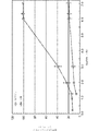
最初に十分な量の浸透圧剤がデバイスに装填される場合、浸透圧溶液の濃度は、薬剤が可溶化されるときに一定のままであり得るが、浸透圧流入領域は増加する。したがって、壁を通して流入する浸透圧水の全体的な量は、浸透圧流入領域が増加すると経時的に増加し、浸透圧溶液は飽和のままである。しかしながら、最初に十分な量の浸透圧剤が装填されない場合、浸透圧溶液の濃度は、経時的に減少するが、浸透圧流入領域は増加する。したがって、時間依存性浸透圧溶液濃度と時間依存性浸透圧流入領域の増加は、どれだけ速く浸透圧溶液が薬物流体製剤を外に押し出すかを決定する。 If a sufficient amount of osmotic agent is initially loaded into the device, the concentration of the osmotic solution may remain constant as the agent is solubilized, but the osmotic inflow area increases. Thus, the overall amount of osmotic water flowing through the wall increases over time as the osmotic pressure inflow region increases and the osmotic solution remains saturated. However, if not initially loaded with a sufficient amount of osmotic agent, the concentration of the osmotic solution decreases over time, but the osmotic inflow region increases. Thus, the increase in the time-dependent osmotic solution concentration and the time-dependent osmotic inflow region determines how fast the osmotic solution pushes the drug fluid formulation out.
一実施形態では、図6A〜図6Cに示されるように、薬物送達デバイスは、貯蔵部614に隣接したコンパートメント652を含み、コンパートメント652は、貯蔵部の壁の透水性部分650(例えばコンパートメントと貯蔵部との間に位置付けられる親水性膜)を介して貯蔵部614内に吸収される水660を収容するように構成される。例えば、このデバイスの実施形態は、子宮などの十分な体液又は水が得られない移植部位に好適であり得る。これらの実施形態では、方法は、ポートを介して水をコンパートメント内に導入することを含む。ある特定の実施形態では、方法は、水がコンパートメント内に導入された後に、コンパートメントと流体連通している空気孔を塞ぐことも含む。よって、空気孔は、充填プロセス中開いたままであってよい。コンパートメントに関連する水注入ポートは、コンパートメント内の水が親水性膜を通して貯蔵部内に移動するときに、負のゲージ圧が発生できないように開いたままであってよい。
In one embodiment, as shown in FIGS. 6A-6C, the drug delivery device includes a
一実施形態では、薬物送達デバイスを患者に挿入することは、患者の尿道を介して薬物送達デバイスを患者の膀胱内に配備することを含む。例えば、デバイスは、尿道などの実の身体の内腔に位置付けられるカテーテル又は膀胱鏡などの配備機器を通して膀胱などの体腔内に配備され得る。配備機器は典型的に、薬物送達デバイスが処方された治療期間の間膀胱又は他の体腔内に留まる一方で、身体の内腔から除去される。例えば、デバイスは非外科的に移植することができ、移植手順が終わった後、数日間、数週間、数ヶ月以上薬物を送達することができる。 In one embodiment, inserting the drug delivery device into the patient includes deploying the drug delivery device into the patient's bladder via the patient's urethra. For example, the device can be deployed in a body cavity such as the bladder through a deployment device such as a catheter or cystoscope positioned in a real body lumen such as the urethra. The deployment device is typically removed from the body lumen while the drug delivery device remains in the bladder or other body cavity for the prescribed treatment period. For example, the device can be implanted non-surgically and the drug can be delivered for days, weeks, months or more after the implantation procedure is complete.
いくつかの実施形態では、デバイスは、独立した手順で、又は別の泌尿器もしくは他の手順又は手術と併せて、他の手順前、手順中、又は手順後のいずれかで、患者の膀胱内に配備され得る。一実施形態では、デバイスは、配備機器を通して薬物送達デバイスを通過させ、配備機器から身体内にデバイスを放出することにより移植される。デバイスが膀胱などの体腔内に配備される場合では、デバイスは、デバイスが配備機器から空洞内に出た時点で、拡張又は高プロファイルの形状などの保持形状を取ることができる。デバイスは、術中、術後、又はその両方のいずれかで、療法もしくは予防のために局所及び/又は局部組織に送達される1つ以上の薬物を放出することができる。放出は制御することができ、長期間にわたって有効量で薬物を放出することができる。その後、デバイスは、除去、吸収、排泄されるか、又はこれらのいくつかの組み合わせが行われ得る。ある特定の実施形態では、デバイスは、膀胱内に存在し、2週間、3週間、4週間、1ヶ月以上など、所定の期間にわたって薬物を放出する。よって、移植された時点で、デバイスは、所望の所定の期間にわたって、所望の量の薬物の長期的、連続的、断続的、又は周期的な放出を提供することができる。ある特定の実施形態では、デバイスは、12時間、24時間、5日間、7日間、10日間、14日間、又は20、25、30、45、60、もしくは90日以上など、長期間にわたって所望の用量の薬物を送達することができる。送達速度及び薬物の投薬量は、送達される薬物及び治療される疾患又は状態に応じて選択され得る。 In some embodiments, the device is placed in the patient's bladder either in an independent procedure or in conjunction with another urinary or other procedure or surgery, either before, during, or after another procedure. Can be deployed. In one embodiment, the device is implanted by passing the drug delivery device through the deployment device and releasing the device from the deployment device into the body. In the case where the device is deployed in a body cavity such as the bladder, the device can assume a retention shape, such as an expanded or high profile shape, when the device exits the deployment device into the cavity. The device can release one or more drugs delivered to local and / or local tissues for therapy or prophylaxis, either intraoperatively, postoperatively, or both. Release can be controlled and the drug can be released in effective amounts over an extended period of time. The device can then be removed, absorbed, excreted, or some combination of these can be performed. In certain embodiments, the device is present in the bladder and releases the drug over a predetermined period, such as 2 weeks, 3 weeks, 4 weeks, 1 month or more. Thus, once implanted, the device can provide long-term, continuous, intermittent, or periodic release of a desired amount of drug over a desired predetermined period. In certain embodiments, the device may be desired over a long period of time, such as 12 hours, 24 hours, 5 days, 7 days, 10 days, 14 days, or more than 20, 25, 30, 45, 60, or 90 days. A dose of drug can be delivered. Delivery rate and drug dosage may be selected depending on the drug to be delivered and the disease or condition being treated.
一実施形態では、図3A〜図3Cに示されるように、流体は薬物の溶液である。別の実施形態では、図5A〜図5Cに示されるように、薬物送達デバイスは、細長い管内に収容される薬物531の固体又は半固体製剤を含み、流体前駆体533は、流体前駆体が細長い管内に導入されたときに、流体前駆体が薬物を溶解して、デバイスから送られる薬物を含有する流体を形成するような、薬物の溶剤である。例えば、薬物がより安定しており、かつ/又は液体形態より固体形態の改善された取り扱いを示す場合、又は薬物の取り扱いに関連する安全上の問題がある場合、デバイスは薬物の固体形態で予め装填され得る。
In one embodiment, the fluid is a drug solution, as shown in FIGS. 3A-3C. In another embodiment, as shown in FIGS. 5A-5C, the drug delivery device comprises a solid or semi-solid formulation of
デバイスは、間質性膀胱炎、放射線膀胱炎、骨盤痛、過活動膀胱症候群、膀胱癌、神経因性膀胱、神経障害性もしくは非神経障害性膀胱−括約筋不全、感染、術後痛、又は膀胱に送達される薬物で治療される他の疾患、障害、及び状態を治療するために使用され得る。デバイスは、膀胱に局所的に、及び膀胱付近の他の部位に局部的に薬物を放出することができる。デバイスは、膀胱容量、コンプライアンス、及び/又は非制御の収縮頻度などの膀胱機能を改善する、膀胱もしくは他の付近の領域の疼通及び不快感を低減する、又は他の作用を有する、あるいはこれらの組み合わせの薬物を送達することができる。膀胱内に配備されたデバイスは、特に腎臓、尿道、尿管、陰茎、精巣、精嚢、輸精管、射精管、前立腺、膣、子宮、卵巣、もしくは卵管、又はこれらの組み合わせを含む、身体の泌尿器もしくは生殖器系内の他の位置など、身体内の他の泌尿生殖器部位に、治療有効量の1つ以上の薬物を送達することもできる。例えば、薬物送達デバイスは、他の疾患、障害、及び状態の中でも、腎結石又は線維症、勃起不全の治療に使用され得る。薬物は、ゲムシタビン、オキサリプラチン、及び/もしくは別の化学療法剤、トロスピウム及び/もしくは別の抗ムスカリン剤、又はリドカイン及び/もしくは別の麻酔剤を含み得る。 The device is interstitial cystitis, radiation cystitis, pelvic pain, overactive bladder syndrome, bladder cancer, neurogenic bladder, neuropathic or non-neuropathic bladder-sphincter failure, infection, postoperative pain, or bladder It can be used to treat other diseases, disorders, and conditions that are treated with drugs delivered to. The device can release the drug locally to the bladder and locally to other sites near the bladder. The device improves bladder function, such as bladder capacity, compliance, and / or uncontrolled contraction frequency, reduces pain and discomfort in the bladder or other nearby areas, or has other effects A combination of drugs can be delivered. Devices deployed in the bladder include bodily, especially including the kidney, urethra, ureter, penis, testis, seminal vesicle, vas deferens, ejaculatory tube, prostate, vagina, uterus, ovary, or fallopian tube, or combinations thereof A therapeutically effective amount of one or more drugs can also be delivered to other urogenital sites in the body, such as the urinary organ or other locations within the genital system. For example, drug delivery devices can be used to treat kidney stones or fibrosis, erectile dysfunction, among other diseases, disorders, and conditions. The drug may include gemcitabine, oxaliplatin, and / or another chemotherapeutic agent, trospium and / or another antimuscarinic agent, or lidocaine and / or another anesthetic agent.
その後、デバイスは、デバイスが吸収性でないか、ないしは別の方法で除去される必要がある場合など、身体から回収され得る。この目的のための回収デバイスは、当該技術分野において既知であるか、又は特別に製造され得る。デバイスはまた、デバイス全体が吸収されるか、又はデバイスが例えば排尿中に膀胱から排出されるのに十分に分解するかのいずれかであるとき、回収が必要でないように、完全に、もしくは部分的に、生浸食性、吸収性、又は生分解性であってもよい。デバイスは、薬物の一部又は好ましくは大半のもしくは全ての薬物が放出されるまで、回収又は吸収されなくてよい。必要な場合、回収と同じ手順中に、又は後刻、新しい薬物装填デバイスを後に移植することができる。 The device can then be recovered from the body, such as when the device is not absorbable or needs to be removed otherwise. Recovery devices for this purpose are known in the art or can be specially manufactured. The device can also be fully or partially so that no recovery is required when either the entire device is absorbed or the device degrades sufficiently to be excreted from the bladder during urination, for example. In particular, it may be bioerodible, absorbable, or biodegradable. The device may not be collected or absorbed until some or preferably most or all of the drug is released. If necessary, a new drug loading device can be implanted later, either during the same procedure as recovery or at a later time.
本発明は、以下の非限定的な実施例を参照することによりさらに理解することができる。 The invention can be further understood by reference to the following non-limiting examples.
本明細書に開示されるデバイスの実施形態が製造され、試験された。一実施例では、10cm(1.02mmID×2.16mmOD)の長さを有するシリコーン管を、230mg/2.3cmの量のNaCl錠剤で充填された親水性HP−93A−100管(2.64mmID×3.05mmOD)に接続した。別の実施例では、13.5cm(0.51mmID×0.94mmOD)の長さを有するシリコーン管を、241mg/2.2cmの量のNaCl錠剤で充填された親水性HP−93A−100管(2.64mmID×3.05mmOD)に接続した。シリコーン管は、メチレンブルー(MB)水溶液で充填され、脱気DI水に浸漬された。目視観察により、水の流動により水溶液を親水性管内に前進させ、空気の小塊は、ピストン又は分離子として機能した。 Embodiments of the devices disclosed herein have been manufactured and tested. In one example, a silicone tube having a length of 10 cm (1.02 mm ID × 2.16 mm OD) is replaced with a hydrophilic HP-93A-100 tube (2.64 mm ID) filled with NaCl tablets in an amount of 230 mg / 2.3 cm. × 3.05 mm OD). In another example, a silicone tube having a length of 13.5 cm (0.51 mm ID × 0.94 mm OD) is a hydrophilic HP-93A-100 tube filled with NaCl tablets in an amount of 241 mg / 2.2 cm ( 2.64 mm ID × 3.05 mm OD). The silicone tube was filled with methylene blue (MB) aqueous solution and immersed in degassed DI water. By visual observation, the aqueous solution was advanced into the hydrophilic tube by the flow of water, and the air blob functioned as a piston or separator.
別の実施例では、固体部と液体部との間に気泡(即ち、空隙又は流体ピストン)を有する、又は有さないユニットのゲムシタビン(薬物)及びクエン酸三ナトリウム(浸透圧剤)放出プロファイルが試験された。図10〜図11に示されるものに類似するデバイスが製造され、試験された。 In another embodiment, the gemcitabine (drug) and trisodium citrate (osmotic agent) release profile of a unit with or without air bubbles (ie, voids or fluid pistons) between the solid and liquid parts. Tested. Devices similar to those shown in FIGS. 10-11 were manufactured and tested.
具体的には、約7.5cmの固体のクエン酸三ナトリウム93%錠剤(1010、1110)及び約15cmの液体ゲムシタビンHCl含有水(5mg FBE/mL)(1032、1132)を含有するデバイスが製造された。長さが5mm、及び500μmの開口部IDを有する空気孔スペーサー開口部(1080、1180)を、シリコーン接着剤で、浸透圧錠剤に隣接した管端部に固定した。長さが5mm、及び300μmの開口部IDを有する溶液注入/放出スペーサー開口部(1008、1108)を、シリコーン接着剤で、反対側の管端部に固定した。注入開口部を通して、シリンジでゲムシタビン溶液を注入した。薬物溶液をユニット内に注入した後、ニチノールピン(1016、1116)を空気孔スペーサー開口部に嵌合させた。液体薬物溶液及び浸透圧錠剤が触れる3つのユニット(図10に示される)、並びに長さが約2cmの空気小塊(1120)が浸透圧錠剤と液体薬物溶液との間に提供される3つのユニット(図11に示される)を準備した。ユニットを37℃の100mLの脱イオン水に設置し、各測定試料が採取される前に、5mLをピペットで入れて出すことを3回行うことにより放出媒体を混合した。 Specifically, a device containing about 7.5 cm of solid trisodium citrate 93% tablets (1010, 1110) and about 15 cm of liquid gemcitabine HCl-containing water (5 mg FBE / mL) (1032, 1132) is manufactured. It was done. An air hole spacer opening (1080, 1180) having an opening ID of 5 mm in length and 500 μm was secured to the tube end adjacent to the osmotic tablet with silicone adhesive. A solution injection / release spacer opening (1008, 1108) having an opening ID of 5 mm in length and 300 μm was secured to the opposite tube end with silicone adhesive. The gemcitabine solution was injected with a syringe through the injection opening. After injecting the drug solution into the unit, Nitinol pins (1016, 1116) were fitted into the air hole spacer openings. Three units (shown in FIG. 10) that the liquid drug solution and osmotic tablet touch, and three air lumps (1120) about 2 cm in length are provided between the osmotic tablet and the liquid drug solution. A unit (shown in FIG. 11) was prepared. The release medium was mixed by placing the unit in 100 mL deionized water at 37 ° C. and pipetting 5 mL three times before each measurement sample was collected.
図13〜図16は、これらの試験の結果を示す。空隙を有するユニット対空隙を有さないユニットについて、図13は、経時的に測定された放出されたゲムシタビン(パーセント)を示し、図14は、経時的なゲムシタビン放出速度を示す。示されるように、空隙ユニットは、デバイスが水に浸漬された後直ぐにゲムシタビンの放出を開始したが、空隙を有さないユニットは、24時間後まで薬物の放出が始まらなかった。意外なことに、図13は、約20%のみのゲムシタビン溶液を放出する空隙を有さないユニットと比較して、空隙を有するユニットが100%のゲムシタビン溶液を放出することができたことを示す。さらに、空隙ユニットは、後の時点でより高いゲムシタビン放出速度を有し、これは、持続放出が望ましい薬物について望ましい。 Figures 13-16 show the results of these tests. For units with voids vs. units without voids, FIG. 13 shows the released gemcitabine (percent) measured over time, and FIG. 14 shows the gemcitabine release rate over time. As shown, the void unit started releasing gemcitabine immediately after the device was immersed in water, but the unit without void did not begin to release drug until 24 hours later. Surprisingly, FIG. 13 shows that the unit with voids was able to release 100% gemcitabine solution compared to the unit without voids that released only about 20% gemcitabine solution. . In addition, the void unit has a higher gemcitabine release rate at a later time, which is desirable for drugs where sustained release is desired.
空隙を有するユニット対空隙を有さないユニットについて、図15は、経時的に放出されたクエン酸塩(浸透圧剤)(パーセント)を示し、図16は、経時的なクエン酸塩放出速度を示す。一般に、図13〜図16は、空隙が数日間浸透圧錠剤と薬物溶液との間で維持されることを示す。さらに、空隙は、100%のゲムシタビンが放出されるまで、浸透圧剤の放出を防止する。よって、空隙は、ピストンとして作用し、薬物を放出する間、浸透圧と薬物部との分離を保ち、高パーセンテージのゲムシタビン放出及び後日の高放出速度をもたらす。 For units with voids versus units without voids, FIG. 15 shows the citrate (osmotic agent) (percent) released over time, and FIG. 16 shows the citrate release rate over time. Show. In general, FIGS. 13-16 show that voids are maintained between osmotic tablets and drug solutions for several days. Furthermore, the voids prevent release of the osmotic agent until 100% gemcitabine is released. Thus, the void acts as a piston and keeps the osmotic pressure and drug part separate during drug release, resulting in a high percentage of gemcitabine release and a high release rate at a later date.
別の実施例では、固体部と液体部との間に空隙を有するユニットを異なる浸透圧剤を用いて製造し、錠剤中の浸透圧剤の変更がどのようにゲムシタビン放出プロファイルを変更させるかを決定した。約30cmのより長い液体コア長を有することを除き、図13〜図16に報告された試験のために準備されたものに類似するデバイスを準備した。試験した浸透圧剤は、(1)90%尿素、10%Lubritab(登録商標)(J.Rettenmaier&Sohne GmbH+Co.KG)、(2)90%尿素、600,000の平均分子量を有する9%ポリ(エチレンオキシド)(「PEO(600K)」)、0.5%Neusilin(登録商標)UFL2(Fuji Chemical Industry Co.,Ltd)、0.5%ステアリン酸マグネシウム、(3)87%ラクトース一水和物、8,000の平均分子量を有する8%ポリエチレングリコール(PEG)、5%Plasdone(商標)K−29/32(ISP Pharmaceuticals)、及び(4)90%NaCl、10%Polyplasdone(商標)XL10(ISP Pharmaceuticals)を含んだ。図17は、デバイスの経時的に放出されたゲムシタビン(パーセント)を示し、図18は、デバイスの経時的なゲムシタビン放出速度を示す。図19は、浸透圧剤に尿素を含有する2つのデバイスの経時的に放出された尿素(パーセント)を示し、図20は、浸透圧剤に尿素を含有する2つのデバイスの経時的な尿素放出速度を示す。 In another embodiment, a unit with a gap between the solid and liquid parts is manufactured using different osmotic agents and how changing the osmotic agent in the tablet changes the gemcitabine release profile. Were determined. A device similar to that prepared for the tests reported in FIGS. 13-16 was prepared except having a longer liquid core length of about 30 cm. The osmotic agents tested were (1) 90% urea, 10% Lubritab® (J. Rettenmeier & Sohne GmbH + Co. KG), (2) 90% urea, 9% poly (ethylene oxide with an average molecular weight of 600,000 ) ("PEO (600K)"), 0.5% Neusilin® UFL2 (Fuji Chemical Industry Co., Ltd), 0.5% magnesium stearate, (3) 87% lactose monohydrate, 8 8% polyethylene glycol (PEG) having an average molecular weight of 1,000, 5% Plasdone ™ K-29 / 32 (ISP Pharmaceuticals), and (4) 90% NaCl, 10% Polyplasmone ™ XL10 (ISP Pharmac) euticals). FIG. 17 shows the gemcitabine (percent) released over time for the device, and FIG. 18 shows the gemcitabine release rate over time for the device. FIG. 19 shows the released urea (percent) over time for two devices containing urea in the osmotic agent, and FIG. 20 shows the urea release over time for the two devices containing urea in the osmotic agent. Indicates speed.
図17〜図20に示されるように、尿素:Lubritab(登録商標)デバイスは、3日目〜14日目までほぼ一定のゲムシタビン流量を示し、14日目に100%のゲムシタビンが放出された。尿素:Lubritab(登録商標)の結果も、尿素の希釈が表面積増加により相殺されることを示す。尿素:PEO(600K)デバイスは、3日目〜7日目までほぼ一定のゲムシタビン流量を示す。尿素:PEO(600K)も、尿素の希釈が表面積の増加により最初は相殺されることを示す。しかしながら、結果は、空隙がゲムシタビンと尿素:PEO(600K)との間で維持されなかったことを示し、これは、PEOによる表面張力の減少に起因し得る。ラクトースデバイスは、薬物放出において非常に長い遅延時間を示す。NaClデバイスは、2日目〜9日目までゲムシタビン流量の増加、及び9日目〜11日目まで一定のゲムシタビン流量を示し、11日目に100%のゲムシタビンが放出された。
As shown in FIGS. 17-20, the urea: Lubritab® device showed almost constant gemcitabine flow from day 3 to
これらの実施例は、空隙デバイスが空隙を有さない類似するデバイスよりも非常に優れていることを示す。空隙デバイスは、一定又は増加した放出速度で、100%のそれらの液体薬物負荷量を放出することができる。よって、薬物送達デバイスは、所望の薬物放出プロファイルに基づき調整することができる。 These examples show that void devices are much better than similar devices that do not have voids. Void devices can release 100% of their liquid drug load at a constant or increased release rate. Thus, the drug delivery device can be adjusted based on the desired drug release profile.
これらのデバイスは有利に、液体形態のみで入手可能な薬物、又は貯蔵のための固体形態のより安定した/安全な薬物を送達することができる。つまり、これらのデバイスは、デバイスの浸透圧挙動又は放出速度を変更することなく、薬物を最適な安定度/溶解度に製剤化することを可能にする。さらに、これらのデバイスは、可撓性の実質的に摩擦がないピストンを提供することによって、既知の剛性浸透圧薬物送達デバイスに関連する問題を解決する。可撓性ピストンはその長さに沿ったねじれ及び/又は湾曲を有するデバイスの輪郭をたどることができるため、このピストン設計は、デバイス本体が可撓性のエラストマー材料から作製されることを可能にする。対照的に、剛性ピストンを有する可撓性デバイスは、ハウジングがピストンの後ろの浸透圧によって膨張するため、ピストンで漏れることが分かった。可撓性デバイスは有利に、剛性デバイスより広範囲の用途及び挿入/移植部位においても使用され得る。 These devices can advantageously deliver drugs that are available only in liquid form, or more stable / safe drugs in solid form for storage. That is, these devices allow the drug to be formulated for optimal stability / solubility without changing the osmotic behavior or release rate of the device. In addition, these devices solve the problems associated with known rigid osmotic drug delivery devices by providing a flexible, substantially frictionless piston. This piston design allows the device body to be made from a flexible elastomeric material, as the flexible piston can follow the contours of the device with twist and / or curvature along its length. To do. In contrast, a flexible device with a rigid piston has been found to leak at the piston as the housing expands due to osmotic pressure behind the piston. Flexible devices can advantageously be used in a wider range of applications and insertion / implantation sites than rigid devices.
本明細書に引用される刊行物及びそれらが引用される資料は、参照により具体的に組み込まれる。本明細書に記載の方法及びデバイスの修正及び変形は、先行する発明を実施するための形態から当業者には明らかであろう。このような修正及び変形は、付属の特許請求の範囲の範囲内であることが意図される。 Publications cited herein and the materials for which they are cited are specifically incorporated by reference. Modifications and variations of the methods and devices described herein will be apparent to those skilled in the art from the preceding detailed description. Such modifications and variations are intended to be within the scope of the appended claims.
Claims (50)
管腔を画定するハウジングと、
前記管腔内で移動可能な浸透圧駆動ピストンと、を備え、
前記ハウジングが、患者の尿道を通した挿入に好適な第1の形状と前記患者の膀胱内での前記デバイスの保持に好適な第2の形状との間で弾性的に変形可能である、医療デバイス。 A medical device,
A housing defining a lumen;
An osmotic pressure drive piston movable within the lumen,
The housing is elastically deformable between a first shape suitable for insertion through the patient's urethra and a second shape suitable for holding the device in the patient's bladder; device.
前記ピストンが、ガスを含み、
前記物質が、薬物を含む、請求項2に記載のデバイス。 The housing comprises an elongated tube;
The piston includes a gas;
The device of claim 2, wherein the substance comprises a drug.
前記ハウジングが、前記細長い管の前記第2の端部に接続され、かつ浸透圧剤が配置される貯蔵部をさらに画定し、
前記ハウジングが、水が前記貯蔵部に入り、かつ前記浸透圧剤と接触することを可能にするための透水性壁をさらに備え、
前記ピストンが、前記浸透圧剤によって発生した浸透圧下で、前記細長い管の前記第1の端部に向かって前記管腔内を前進して、前記放出構造を介して前記物質を前記管腔の外に排出させるように動作可能である、請求項3に記載のデバイス。 The elongate tube comprises a first end having a release structure for releasing the substance, and an opposite second end;
The housing is further connected to the second end of the elongated tube and further defines a reservoir in which an osmotic agent is disposed;
The housing further comprises a water permeable wall for allowing water to enter the reservoir and contact the osmotic agent;
The piston is advanced through the lumen toward the first end of the elongate tube under osmotic pressure generated by the osmotic agent to deliver the substance through the release structure to the lumen. The device of claim 3, wherein the device is operable to drain out.
前記ハウジングが、前記細長い管の前記第2の端部に接続され、かつ浸透圧剤が配置される貯蔵部をさらに画定し、
前記ハウジングが、水が前記貯蔵部に入り、かつ前記浸透圧剤と接触することを可能にするための透水性壁をさらに備え、
前記デバイスが、前記流体又はその前駆体を受容したときに、前記ピストンが前記流体と前記浸透圧剤との間に形成されたガスを含むように構成され、
前記デバイスが、前記透水性壁を介して前記貯蔵部内に水を吸収し、前記浸透圧剤によって発生した浸透圧を介して前記細長い管を通して前記ガスピストンを前進させて、前記放出構造を介して前記デバイスから前記流体を送るように構成される、請求項1に記載のデバイス。 The housing is an elongated tube having a first end with a discharge structure for discharging fluid and an opposite second end to receive a fluid drug or precursor thereof. Comprising an elongated tube,
The housing is further connected to the second end of the elongated tube and further defines a reservoir in which an osmotic agent is disposed;
The housing further comprises a water permeable wall for allowing water to enter the reservoir and contact the osmotic agent;
When the device receives the fluid or a precursor thereof, the piston includes a gas formed between the fluid and the osmotic agent;
The device absorbs water into the reservoir through the water permeable wall, advances the gas piston through the elongated tube through the osmotic pressure generated by the osmotic agent, and through the discharge structure. The device of claim 1, configured to deliver the fluid from the device.
前記流体前駆体が、前記細長い管内に前記流体前駆体を受容したときに、前記流体前駆体が前記薬物を溶解して、前記デバイスから送られる前記流体を形成するような、前記薬物の溶剤である、請求項26に記載のデバイス。 The device further comprises a solid or semi-solid formulation of the drug contained within the elongated tube;
With the drug solvent, such that when the fluid precursor receives the fluid precursor in the elongated tube, the fluid precursor dissolves the drug to form the fluid delivered from the device. 27. The device of claim 26, wherein:
請求項3〜28及び31〜33のいずれか一項に記載のデバイスと、
前記物質、前記流体、又はその前駆体を収容する容器と、
前記流体又は前駆体を前記容器から前記細長い管内に移すためのデバイスと、を含む、キット。 A kit,
A device according to any one of claims 3 to 28 and 31 to 33;
A container containing the substance, the fluid, or a precursor thereof;
A device for transferring the fluid or precursor from the container into the elongated tube.
前記容器が、前記薬物の溶剤を含む前駆体を収容する、請求項34に記載のキット。 The device further comprises a solid or semi-solid formulation of the drug contained within the elongated tube;
35. The kit of claim 34, wherein the container contains a precursor containing a solvent for the drug.
前記キットが、前記空気孔を塞ぐように構成された1つ以上のプラグをさらに含む、請求項34に記載のキット。 34. The drug delivery device is the device of any one of claims 27 and 33,
35. The kit of claim 34, wherein the kit further comprises one or more plugs configured to plug the air holes.
前記患者の尿道を介して薬物送達デバイスを患者の膀胱内に配備することであって、前記デバイスが、管腔を画定するハウジング及び前記患者に分注される流体を含む、配備することを含み、
前記デバイスが、前記尿道を通した挿入に好適な第1の形状と前記膀胱内での前記デバイスの保持に好適な第2の形状との間で弾性的に変形可能であり、
前記デバイスが、前記管腔内で浸透圧駆動ピストンを移動させて、前記流体を前記デバイスから排出するように動作可能である、方法。 A method for delivering a drug comprising:
Deploying a drug delivery device through the patient's urethra into the patient's bladder, the device comprising a housing defining a lumen and a fluid dispensed to the patient; ,
The device is elastically deformable between a first shape suitable for insertion through the urethra and a second shape suitable for holding the device in the bladder;
The method wherein the device is operable to move an osmotic drive piston within the lumen to drain the fluid from the device.
前記ピストンが、ガスを含み、
前記流体が、薬物を含む、請求項39に記載の方法。 The housing comprises an elongated tube;
The piston includes a gas;
40. The method of claim 39, wherein the fluid comprises a drug.
前記ハウジングが、前記細長い管の前記第2の端部に接続され、かつ浸透圧剤が配置される貯蔵部をさらに形成し、
前記ハウジングが、水が前記貯蔵部に入り、かつ前記浸透圧剤と接触することを可能にするための透水性壁をさらに備え、
前記ピストンが、浸透圧剤によって発生した浸透圧下で、前記細長い管の前記第1の端部に向かって前記管腔内を前進して、前記放出構造を介して前記流体を前記管腔の外に排出させるように動作可能である、請求項40に記載の方法。 The elongated tube comprises a first end having a discharge structure for discharging the fluid, and an opposite second end;
The housing further forms a reservoir connected to the second end of the elongated tube and in which an osmotic agent is disposed;
The housing further comprises a water permeable wall for allowing water to enter the reservoir and contact the osmotic agent;
The piston is advanced in the lumen toward the first end of the elongated tube under osmotic pressure generated by an osmotic agent to allow the fluid to pass out of the lumen through the discharge structure. 41. The method of claim 40, wherein the method is operable to cause
前記流体前駆体が、前記細長い管内に前記流体前駆体を導入したときに、前記流体前駆体が前記薬物を溶解して、前記デバイスから送られる前記流体を形成するような、前記薬物の溶剤である、請求項43に記載の方法。 The device further comprises a solid or semi-solid formulation of the drug contained within the elongated tube;
With the drug solvent, such that when the fluid precursor introduces the fluid precursor into the elongated tube, the fluid precursor dissolves the drug to form the fluid delivered from the device. 44. The method of claim 43, wherein:
前記方法が、水を前記コンパートメント内に導入することをさらに含む、請求項41に記載の方法。 The drug delivery device further comprises a compartment adjacent to the reservoir, the compartment configured to contain water that is absorbed into the reservoir through the water permeable wall of the reservoir;
42. The method of claim 41, wherein the method further comprises introducing water into the compartment.
Applications Claiming Priority (3)
| Application Number | Priority Date | Filing Date | Title |
|---|---|---|---|
| US201361899982P | 2013-11-05 | 2013-11-05 | |
| US61/899,982 | 2013-11-05 | ||
| PCT/US2014/064063 WO2015069723A1 (en) | 2013-11-05 | 2014-11-05 | Osmotic drug delivery devices, kits, and methods |
Publications (2)
| Publication Number | Publication Date |
|---|---|
| JP2017500171A true JP2017500171A (en) | 2017-01-05 |
| JP2017500171A5 JP2017500171A5 (en) | 2017-12-07 |
Family
ID=51946057
Family Applications (1)
| Application Number | Title | Priority Date | Filing Date |
|---|---|---|---|
| JP2016552464A Pending JP2017500171A (en) | 2013-11-05 | 2014-11-05 | Osmotic drug delivery device, kit and method |
Country Status (10)
| Country | Link |
|---|---|
| US (1) | US20160279399A1 (en) |
| EP (1) | EP3065807A1 (en) |
| JP (1) | JP2017500171A (en) |
| KR (1) | KR20160083061A (en) |
| CN (1) | CN105792880A (en) |
| BR (1) | BR112016010103A8 (en) |
| CA (1) | CA2929554A1 (en) |
| IL (1) | IL245445A0 (en) |
| RU (1) | RU2016120199A (en) |
| WO (1) | WO2015069723A1 (en) |
Families Citing this family (10)
| Publication number | Priority date | Publication date | Assignee | Title |
|---|---|---|---|---|
| JP2016508842A (en) | 2013-03-05 | 2016-03-24 | タリス バイオメディカル エルエルシー | Drug delivery device and method for controlled drug release through an opening in the device |
| KR102338079B1 (en) * | 2014-03-06 | 2021-12-09 | 타리스 바이오메디컬 엘엘씨 | Drug delivery systems and methods for treatment of bladder cancer with gemcitabine |
| EP3277363B1 (en) | 2015-03-30 | 2019-06-19 | TARIS Biomedical LLC | Devices for local delivery of drug to upper urinary tract |
| US9867974B2 (en) * | 2015-06-01 | 2018-01-16 | Wisconsin Alumni Research Foundation | Microfluidic device for multiplexed point source administration of compounds |
| ES2873084T3 (en) * | 2017-02-01 | 2021-11-03 | Taris Biomedical Llc | Devices for in vivo drug delivery |
| CN110944645A (en) | 2017-07-25 | 2020-03-31 | 塔里斯生物医药公司 | Method for treating tumor metastasis |
| US11045589B2 (en) | 2017-09-22 | 2021-06-29 | Becton, Dickinson And Company | 4% trisodium citrate solution for use as a catheter lock solution |
| MX2021001264A (en) | 2018-08-01 | 2021-07-02 | Taris Biomedical Llc | Methods of treating overactive bladder using trospium. |
| CN109589491B (en) * | 2019-01-29 | 2024-01-09 | 上海安翰医疗技术有限公司 | Automatic drug delivery device |
| AU2021354328A1 (en) * | 2020-09-30 | 2023-05-18 | Modibodi Australia Pty Ltd | A fabric insert |
Citations (5)
| Publication number | Priority date | Publication date | Assignee | Title |
|---|---|---|---|---|
| JP2006521897A (en) * | 2003-03-31 | 2006-09-28 | アルザ・コーポレーション | Osmotic pump with means for dissipating internal pressure |
| US20090142313A1 (en) * | 2007-11-22 | 2009-06-04 | Bayer Schering Pharma Oy | Vaginal delivery system |
| JP2011505988A (en) * | 2007-12-11 | 2011-03-03 | マサチューセッツ インスチテュート オブ テクノロジー | Implantable drug delivery device and method for treating bladder and other body vesicles or lumens |
| JP2011530390A (en) * | 2008-08-09 | 2011-12-22 | マサチューセッツ インスチテュート オブ テクノロジー | Implantable drug delivery device and method for treating male genitourinary and surrounding tissues |
| WO2013064745A1 (en) * | 2011-11-01 | 2013-05-10 | Bayer Oy | Osmotically active vaginal delivery system |
Family Cites Families (16)
| Publication number | Priority date | Publication date | Assignee | Title |
|---|---|---|---|---|
| GB2155889B (en) * | 1984-03-21 | 1988-03-02 | Alza Corp | Dispenser-capsule |
| MY125870A (en) * | 1997-07-25 | 2006-08-30 | Alza Corp | Osmotic delivery system flow modulator apparatus and method |
| US6436091B1 (en) * | 1999-11-16 | 2002-08-20 | Microsolutions, Inc. | Methods and implantable devices and systems for long term delivery of a pharmaceutical agent |
| US8133501B2 (en) * | 2002-02-08 | 2012-03-13 | Boston Scientific Scimed, Inc. | Implantable or insertable medical devices for controlled drug delivery |
| US8257963B2 (en) * | 2007-06-01 | 2012-09-04 | Depuy Mitek, Inc. | Chondrocyte container and method of use |
| DK1933810T3 (en) | 2005-08-11 | 2013-01-28 | Childrens Medical Center | Intravesical drug delivery device and method |
| DK2445571T3 (en) | 2009-06-26 | 2013-02-25 | Taris Biomedical Inc | Solid drug tablets for implantable drug delivery devices |
| US8721621B2 (en) | 2009-09-10 | 2014-05-13 | Taris Biomedical, Inc. | Systems and methods for deploying devices to genitourinary sites |
| US9017312B2 (en) | 2009-09-10 | 2015-04-28 | Taris Biomedical Llc | Implantable device for controlled drug delivery |
| JP2013514837A (en) | 2009-12-17 | 2013-05-02 | タリス バイオメディカル,インコーポレイテッド | Implantable device with tolerance in the bladder and method of treatment |
| WO2011112723A2 (en) * | 2010-03-09 | 2011-09-15 | Board Of Regents Of The University Of Texas System | Electro-osmotic pumps, systems, methods, and compositions |
| ES2832524T3 (en) | 2010-08-05 | 2021-06-10 | Taris Biomedical Llc | Ureteral Stent Drug Delivery Device and Kit |
| US9457176B2 (en) | 2010-10-06 | 2016-10-04 | Taris Biomedical Llc | Implantable drug delivery device with bladder retention feature |
| WO2012048114A1 (en) * | 2010-10-06 | 2012-04-12 | Taris Biomedical, Inc. | Time-selective bioresorbable or collapsible drug delivery systems and methods |
| US9114111B2 (en) | 2011-01-10 | 2015-08-25 | Allergan, Inc. | Methods for sustained treatment of bladder pain and irritative voiding |
| JP6517186B2 (en) | 2013-03-15 | 2019-05-22 | タリス バイオメディカル エルエルシー | Drug delivery device comprising a drug permeable component and method |
-
2014
- 2014-11-05 CN CN201480063520.5A patent/CN105792880A/en active Pending
- 2014-11-05 JP JP2016552464A patent/JP2017500171A/en active Pending
- 2014-11-05 BR BR112016010103A patent/BR112016010103A8/en not_active IP Right Cessation
- 2014-11-05 WO PCT/US2014/064063 patent/WO2015069723A1/en active Application Filing
- 2014-11-05 EP EP14802296.5A patent/EP3065807A1/en not_active Withdrawn
- 2014-11-05 US US15/033,692 patent/US20160279399A1/en not_active Abandoned
- 2014-11-05 RU RU2016120199A patent/RU2016120199A/en not_active Application Discontinuation
- 2014-11-05 KR KR1020167014800A patent/KR20160083061A/en not_active Application Discontinuation
- 2014-11-05 CA CA2929554A patent/CA2929554A1/en not_active Abandoned
-
2016
- 2016-05-03 IL IL245445A patent/IL245445A0/en unknown
Patent Citations (5)
| Publication number | Priority date | Publication date | Assignee | Title |
|---|---|---|---|---|
| JP2006521897A (en) * | 2003-03-31 | 2006-09-28 | アルザ・コーポレーション | Osmotic pump with means for dissipating internal pressure |
| US20090142313A1 (en) * | 2007-11-22 | 2009-06-04 | Bayer Schering Pharma Oy | Vaginal delivery system |
| JP2011505988A (en) * | 2007-12-11 | 2011-03-03 | マサチューセッツ インスチテュート オブ テクノロジー | Implantable drug delivery device and method for treating bladder and other body vesicles or lumens |
| JP2011530390A (en) * | 2008-08-09 | 2011-12-22 | マサチューセッツ インスチテュート オブ テクノロジー | Implantable drug delivery device and method for treating male genitourinary and surrounding tissues |
| WO2013064745A1 (en) * | 2011-11-01 | 2013-05-10 | Bayer Oy | Osmotically active vaginal delivery system |
Also Published As
| Publication number | Publication date |
|---|---|
| US20160279399A1 (en) | 2016-09-29 |
| CN105792880A (en) | 2016-07-20 |
| BR112016010103A8 (en) | 2018-01-30 |
| KR20160083061A (en) | 2016-07-11 |
| EP3065807A1 (en) | 2016-09-14 |
| WO2015069723A1 (en) | 2015-05-14 |
| CA2929554A1 (en) | 2015-05-14 |
| IL245445A0 (en) | 2016-06-30 |
| RU2016120199A (en) | 2017-12-11 |
| RU2016120199A3 (en) | 2018-06-29 |
Similar Documents
| Publication | Publication Date | Title |
|---|---|---|
| JP7122999B2 (en) | Drug delivery device with drug permeable component and method | |
| JP6743213B2 (en) | Intravesical drug delivery device | |
| JP5945544B2 (en) | Time-selective bioabsorbable or disintegratable drug delivery system and method | |
| ES2637388T3 (en) | Implantable device for the controlled release of a low solubility drug | |
| RU2669407C2 (en) | Drug delivery devices and methods for drug delivery | |
| JP2017500171A (en) | Osmotic drug delivery device, kit and method | |
| JP7425534B2 (en) | Drug delivery devices and methods with drug permeable components | |
| JP2013504584A (en) | Implantable device for controlled delivery of drugs | |
| BRPI1014320B1 (en) | drug dosage form, and implantable drug dispensing device | |
| KR20200087147A (en) | Drug delivery device and method for use with a urine catheter |
Legal Events
| Date | Code | Title | Description |
|---|---|---|---|
| A521 | Request for written amendment filed |
Free format text: JAPANESE INTERMEDIATE CODE: A523 Effective date: 20171025 |
|
| A621 | Written request for application examination |
Free format text: JAPANESE INTERMEDIATE CODE: A621 Effective date: 20171025 |
|
| A977 | Report on retrieval |
Free format text: JAPANESE INTERMEDIATE CODE: A971007 Effective date: 20180905 |
|
| A131 | Notification of reasons for refusal |
Free format text: JAPANESE INTERMEDIATE CODE: A131 Effective date: 20180910 |
|
| A02 | Decision of refusal |
Free format text: JAPANESE INTERMEDIATE CODE: A02 Effective date: 20190401 |