JP2017500126A - Humidification system connection - Google Patents
Humidification system connection Download PDFInfo
- Publication number
- JP2017500126A JP2017500126A JP2016541360A JP2016541360A JP2017500126A JP 2017500126 A JP2017500126 A JP 2017500126A JP 2016541360 A JP2016541360 A JP 2016541360A JP 2016541360 A JP2016541360 A JP 2016541360A JP 2017500126 A JP2017500126 A JP 2017500126A
- Authority
- JP
- Japan
- Prior art keywords
- circuit connector
- humidification chamber
- base unit
- outlet
- humidification
- Prior art date
- Legal status (The legal status is an assumption and is not a legal conclusion. Google has not performed a legal analysis and makes no representation as to the accuracy of the status listed.)
- Granted
Links
- 239000012530 fluid Substances 0.000 claims abstract description 27
- 238000004891 communication Methods 0.000 claims abstract description 9
- 238000000034 method Methods 0.000 claims description 26
- 230000003434 inspiratory effect Effects 0.000 claims description 9
- 239000012190 activator Substances 0.000 claims description 8
- 239000007788 liquid Substances 0.000 claims description 8
- 230000029058 respiratory gaseous exchange Effects 0.000 claims description 8
- 230000008878 coupling Effects 0.000 abstract description 5
- 238000010168 coupling process Methods 0.000 abstract description 5
- 238000005859 coupling reaction Methods 0.000 abstract description 5
- 239000007789 gas Substances 0.000 description 61
- 230000008901 benefit Effects 0.000 description 13
- 238000003780 insertion Methods 0.000 description 11
- 230000037431 insertion Effects 0.000 description 11
- XLYOFNOQVPJJNP-UHFFFAOYSA-N water Substances O XLYOFNOQVPJJNP-UHFFFAOYSA-N 0.000 description 8
- 238000010438 heat treatment Methods 0.000 description 7
- 230000006870 function Effects 0.000 description 5
- 238000009833 condensation Methods 0.000 description 4
- 230000005494 condensation Effects 0.000 description 4
- 230000000994 depressogenic effect Effects 0.000 description 4
- 238000012986 modification Methods 0.000 description 4
- 230000004048 modification Effects 0.000 description 4
- 238000007789 sealing Methods 0.000 description 4
- 210000003414 extremity Anatomy 0.000 description 3
- 238000002357 laparoscopic surgery Methods 0.000 description 3
- 230000008569 process Effects 0.000 description 3
- 238000002644 respiratory therapy Methods 0.000 description 3
- 239000000523 sample Substances 0.000 description 3
- 230000009471 action Effects 0.000 description 2
- 230000008859 change Effects 0.000 description 2
- 230000000295 complement effect Effects 0.000 description 2
- 238000001816 cooling Methods 0.000 description 2
- 238000001035 drying Methods 0.000 description 2
- 239000000428 dust Substances 0.000 description 2
- 239000000463 material Substances 0.000 description 2
- 230000003287 optical effect Effects 0.000 description 2
- 239000013307 optical fiber Substances 0.000 description 2
- 230000000241 respiratory effect Effects 0.000 description 2
- 230000000717 retained effect Effects 0.000 description 2
- 239000000758 substrate Substances 0.000 description 2
- 206010002091 Anaesthesia Diseases 0.000 description 1
- 241001631457 Cannula Species 0.000 description 1
- 210000000683 abdominal cavity Anatomy 0.000 description 1
- XAGFODPZIPBFFR-UHFFFAOYSA-N aluminium Chemical compound [Al] XAGFODPZIPBFFR-UHFFFAOYSA-N 0.000 description 1
- 229910052782 aluminium Inorganic materials 0.000 description 1
- 230000037005 anaesthesia Effects 0.000 description 1
- 238000013459 approach Methods 0.000 description 1
- 238000005452 bending Methods 0.000 description 1
- 238000000576 coating method Methods 0.000 description 1
- 239000004020 conductor Substances 0.000 description 1
- 238000000354 decomposition reaction Methods 0.000 description 1
- 230000001419 dependent effect Effects 0.000 description 1
- 230000000881 depressing effect Effects 0.000 description 1
- 238000010586 diagram Methods 0.000 description 1
- 239000004744 fabric Substances 0.000 description 1
- 210000003811 finger Anatomy 0.000 description 1
- 239000011521 glass Substances 0.000 description 1
- 238000010348 incorporation Methods 0.000 description 1
- 230000007257 malfunction Effects 0.000 description 1
- 230000013011 mating Effects 0.000 description 1
- 230000002093 peripheral effect Effects 0.000 description 1
- 238000012545 processing Methods 0.000 description 1
- 239000012858 resilient material Substances 0.000 description 1
- 238000000926 separation method Methods 0.000 description 1
- 238000001356 surgical procedure Methods 0.000 description 1
- 210000003813 thumb Anatomy 0.000 description 1
- 238000011282 treatment Methods 0.000 description 1
- 238000009423 ventilation Methods 0.000 description 1
- 210000001835 viscera Anatomy 0.000 description 1
- 230000000007 visual effect Effects 0.000 description 1
- 239000002699 waste material Substances 0.000 description 1
Images


Classifications
-
- A—HUMAN NECESSITIES
- A61—MEDICAL OR VETERINARY SCIENCE; HYGIENE
- A61M—DEVICES FOR INTRODUCING MEDIA INTO, OR ONTO, THE BODY; DEVICES FOR TRANSDUCING BODY MEDIA OR FOR TAKING MEDIA FROM THE BODY; DEVICES FOR PRODUCING OR ENDING SLEEP OR STUPOR
- A61M39/00—Tubes, tube connectors, tube couplings, valves, access sites or the like, specially adapted for medical use
- A61M39/10—Tube connectors; Tube couplings
- A61M39/12—Tube connectors; Tube couplings for joining a flexible tube to a rigid attachment
-
- A—HUMAN NECESSITIES
- A61—MEDICAL OR VETERINARY SCIENCE; HYGIENE
- A61M—DEVICES FOR INTRODUCING MEDIA INTO, OR ONTO, THE BODY; DEVICES FOR TRANSDUCING BODY MEDIA OR FOR TAKING MEDIA FROM THE BODY; DEVICES FOR PRODUCING OR ENDING SLEEP OR STUPOR
- A61M16/00—Devices for influencing the respiratory system of patients by gas treatment, e.g. mouth-to-mouth respiration; Tracheal tubes
- A61M16/021—Devices for influencing the respiratory system of patients by gas treatment, e.g. mouth-to-mouth respiration; Tracheal tubes operated by electrical means
-
- A—HUMAN NECESSITIES
- A61—MEDICAL OR VETERINARY SCIENCE; HYGIENE
- A61M—DEVICES FOR INTRODUCING MEDIA INTO, OR ONTO, THE BODY; DEVICES FOR TRANSDUCING BODY MEDIA OR FOR TAKING MEDIA FROM THE BODY; DEVICES FOR PRODUCING OR ENDING SLEEP OR STUPOR
- A61M16/00—Devices for influencing the respiratory system of patients by gas treatment, e.g. mouth-to-mouth respiration; Tracheal tubes
- A61M16/08—Bellows; Connecting tubes ; Water traps; Patient circuits
- A61M16/0816—Joints or connectors
-
- A—HUMAN NECESSITIES
- A61—MEDICAL OR VETERINARY SCIENCE; HYGIENE
- A61M—DEVICES FOR INTRODUCING MEDIA INTO, OR ONTO, THE BODY; DEVICES FOR TRANSDUCING BODY MEDIA OR FOR TAKING MEDIA FROM THE BODY; DEVICES FOR PRODUCING OR ENDING SLEEP OR STUPOR
- A61M16/00—Devices for influencing the respiratory system of patients by gas treatment, e.g. mouth-to-mouth respiration; Tracheal tubes
- A61M16/08—Bellows; Connecting tubes ; Water traps; Patient circuits
- A61M16/0875—Connecting tubes
-
- A—HUMAN NECESSITIES
- A61—MEDICAL OR VETERINARY SCIENCE; HYGIENE
- A61M—DEVICES FOR INTRODUCING MEDIA INTO, OR ONTO, THE BODY; DEVICES FOR TRANSDUCING BODY MEDIA OR FOR TAKING MEDIA FROM THE BODY; DEVICES FOR PRODUCING OR ENDING SLEEP OR STUPOR
- A61M16/00—Devices for influencing the respiratory system of patients by gas treatment, e.g. mouth-to-mouth respiration; Tracheal tubes
- A61M16/08—Bellows; Connecting tubes ; Water traps; Patient circuits
- A61M16/0883—Circuit type
-
- A—HUMAN NECESSITIES
- A61—MEDICAL OR VETERINARY SCIENCE; HYGIENE
- A61M—DEVICES FOR INTRODUCING MEDIA INTO, OR ONTO, THE BODY; DEVICES FOR TRANSDUCING BODY MEDIA OR FOR TAKING MEDIA FROM THE BODY; DEVICES FOR PRODUCING OR ENDING SLEEP OR STUPOR
- A61M16/00—Devices for influencing the respiratory system of patients by gas treatment, e.g. mouth-to-mouth respiration; Tracheal tubes
- A61M16/10—Preparation of respiratory gases or vapours
- A61M16/1075—Preparation of respiratory gases or vapours by influencing the temperature
- A61M16/1085—Preparation of respiratory gases or vapours by influencing the temperature after being humidified or mixed with a beneficial agent
-
- A—HUMAN NECESSITIES
- A61—MEDICAL OR VETERINARY SCIENCE; HYGIENE
- A61M—DEVICES FOR INTRODUCING MEDIA INTO, OR ONTO, THE BODY; DEVICES FOR TRANSDUCING BODY MEDIA OR FOR TAKING MEDIA FROM THE BODY; DEVICES FOR PRODUCING OR ENDING SLEEP OR STUPOR
- A61M16/00—Devices for influencing the respiratory system of patients by gas treatment, e.g. mouth-to-mouth respiration; Tracheal tubes
- A61M16/10—Preparation of respiratory gases or vapours
- A61M16/1075—Preparation of respiratory gases or vapours by influencing the temperature
- A61M16/109—Preparation of respiratory gases or vapours by influencing the temperature the humidifying liquid or the beneficial agent
-
- A—HUMAN NECESSITIES
- A61—MEDICAL OR VETERINARY SCIENCE; HYGIENE
- A61M—DEVICES FOR INTRODUCING MEDIA INTO, OR ONTO, THE BODY; DEVICES FOR TRANSDUCING BODY MEDIA OR FOR TAKING MEDIA FROM THE BODY; DEVICES FOR PRODUCING OR ENDING SLEEP OR STUPOR
- A61M16/00—Devices for influencing the respiratory system of patients by gas treatment, e.g. mouth-to-mouth respiration; Tracheal tubes
- A61M16/10—Preparation of respiratory gases or vapours
- A61M16/1075—Preparation of respiratory gases or vapours by influencing the temperature
- A61M16/1095—Preparation of respiratory gases or vapours by influencing the temperature in the connecting tubes
-
- A—HUMAN NECESSITIES
- A61—MEDICAL OR VETERINARY SCIENCE; HYGIENE
- A61M—DEVICES FOR INTRODUCING MEDIA INTO, OR ONTO, THE BODY; DEVICES FOR TRANSDUCING BODY MEDIA OR FOR TAKING MEDIA FROM THE BODY; DEVICES FOR PRODUCING OR ENDING SLEEP OR STUPOR
- A61M16/00—Devices for influencing the respiratory system of patients by gas treatment, e.g. mouth-to-mouth respiration; Tracheal tubes
- A61M16/10—Preparation of respiratory gases or vapours
- A61M16/14—Preparation of respiratory gases or vapours by mixing different fluids, one of them being in a liquid phase
- A61M16/16—Devices to humidify the respiration air
-
- H—ELECTRICITY
- H01—ELECTRIC ELEMENTS
- H01R—ELECTRICALLY-CONDUCTIVE CONNECTIONS; STRUCTURAL ASSOCIATIONS OF A PLURALITY OF MUTUALLY-INSULATED ELECTRICAL CONNECTING ELEMENTS; COUPLING DEVICES; CURRENT COLLECTORS
- H01R13/00—Details of coupling devices of the kinds covered by groups H01R12/70 or H01R24/00 - H01R33/00
- H01R13/005—Electrical coupling combined with fluidic coupling
-
- A—HUMAN NECESSITIES
- A61—MEDICAL OR VETERINARY SCIENCE; HYGIENE
- A61M—DEVICES FOR INTRODUCING MEDIA INTO, OR ONTO, THE BODY; DEVICES FOR TRANSDUCING BODY MEDIA OR FOR TAKING MEDIA FROM THE BODY; DEVICES FOR PRODUCING OR ENDING SLEEP OR STUPOR
- A61M13/00—Insufflators for therapeutic or disinfectant purposes, i.e. devices for blowing a gas, powder or vapour into the body
- A61M13/003—Blowing gases other than for carrying powders, e.g. for inflating, dilating or rinsing
-
- A—HUMAN NECESSITIES
- A61—MEDICAL OR VETERINARY SCIENCE; HYGIENE
- A61M—DEVICES FOR INTRODUCING MEDIA INTO, OR ONTO, THE BODY; DEVICES FOR TRANSDUCING BODY MEDIA OR FOR TAKING MEDIA FROM THE BODY; DEVICES FOR PRODUCING OR ENDING SLEEP OR STUPOR
- A61M16/00—Devices for influencing the respiratory system of patients by gas treatment, e.g. mouth-to-mouth respiration; Tracheal tubes
- A61M16/0057—Pumps therefor
- A61M16/0066—Blowers or centrifugal pumps
- A61M16/0069—Blowers or centrifugal pumps the speed thereof being controlled by respiratory parameters, e.g. by inhalation
-
- A—HUMAN NECESSITIES
- A61—MEDICAL OR VETERINARY SCIENCE; HYGIENE
- A61M—DEVICES FOR INTRODUCING MEDIA INTO, OR ONTO, THE BODY; DEVICES FOR TRANSDUCING BODY MEDIA OR FOR TAKING MEDIA FROM THE BODY; DEVICES FOR PRODUCING OR ENDING SLEEP OR STUPOR
- A61M16/00—Devices for influencing the respiratory system of patients by gas treatment, e.g. mouth-to-mouth respiration; Tracheal tubes
- A61M16/06—Respiratory or anaesthetic masks
-
- A—HUMAN NECESSITIES
- A61—MEDICAL OR VETERINARY SCIENCE; HYGIENE
- A61M—DEVICES FOR INTRODUCING MEDIA INTO, OR ONTO, THE BODY; DEVICES FOR TRANSDUCING BODY MEDIA OR FOR TAKING MEDIA FROM THE BODY; DEVICES FOR PRODUCING OR ENDING SLEEP OR STUPOR
- A61M16/00—Devices for influencing the respiratory system of patients by gas treatment, e.g. mouth-to-mouth respiration; Tracheal tubes
- A61M16/08—Bellows; Connecting tubes ; Water traps; Patient circuits
- A61M16/0816—Joints or connectors
- A61M16/0833—T- or Y-type connectors, e.g. Y-piece
-
- A—HUMAN NECESSITIES
- A61—MEDICAL OR VETERINARY SCIENCE; HYGIENE
- A61M—DEVICES FOR INTRODUCING MEDIA INTO, OR ONTO, THE BODY; DEVICES FOR TRANSDUCING BODY MEDIA OR FOR TAKING MEDIA FROM THE BODY; DEVICES FOR PRODUCING OR ENDING SLEEP OR STUPOR
- A61M39/00—Tubes, tube connectors, tube couplings, valves, access sites or the like, specially adapted for medical use
- A61M39/10—Tube connectors; Tube couplings
- A61M2039/1022—Tube connectors; Tube couplings additionally providing electrical connection
-
- A—HUMAN NECESSITIES
- A61—MEDICAL OR VETERINARY SCIENCE; HYGIENE
- A61M—DEVICES FOR INTRODUCING MEDIA INTO, OR ONTO, THE BODY; DEVICES FOR TRANSDUCING BODY MEDIA OR FOR TAKING MEDIA FROM THE BODY; DEVICES FOR PRODUCING OR ENDING SLEEP OR STUPOR
- A61M2205/00—General characteristics of the apparatus
- A61M2205/33—Controlling, regulating or measuring
- A61M2205/3368—Temperature
-
- A—HUMAN NECESSITIES
- A61—MEDICAL OR VETERINARY SCIENCE; HYGIENE
- A61M—DEVICES FOR INTRODUCING MEDIA INTO, OR ONTO, THE BODY; DEVICES FOR TRANSDUCING BODY MEDIA OR FOR TAKING MEDIA FROM THE BODY; DEVICES FOR PRODUCING OR ENDING SLEEP OR STUPOR
- A61M2205/00—General characteristics of the apparatus
- A61M2205/36—General characteristics of the apparatus related to heating or cooling
- A61M2205/3653—General characteristics of the apparatus related to heating or cooling by Joule effect, i.e. electric resistance
-
- A—HUMAN NECESSITIES
- A61—MEDICAL OR VETERINARY SCIENCE; HYGIENE
- A61M—DEVICES FOR INTRODUCING MEDIA INTO, OR ONTO, THE BODY; DEVICES FOR TRANSDUCING BODY MEDIA OR FOR TAKING MEDIA FROM THE BODY; DEVICES FOR PRODUCING OR ENDING SLEEP OR STUPOR
- A61M2205/00—General characteristics of the apparatus
- A61M2205/50—General characteristics of the apparatus with microprocessors or computers
- A61M2205/502—User interfaces, e.g. screens or keyboards
-
- A—HUMAN NECESSITIES
- A61—MEDICAL OR VETERINARY SCIENCE; HYGIENE
- A61M—DEVICES FOR INTRODUCING MEDIA INTO, OR ONTO, THE BODY; DEVICES FOR TRANSDUCING BODY MEDIA OR FOR TAKING MEDIA FROM THE BODY; DEVICES FOR PRODUCING OR ENDING SLEEP OR STUPOR
- A61M2205/00—General characteristics of the apparatus
- A61M2205/60—General characteristics of the apparatus with identification means
- A61M2205/6045—General characteristics of the apparatus with identification means having complementary physical shapes for indexing or registration purposes
Abstract
加湿システムのための回路コネクタであって、当該システムが加湿チャンバにより係合されるように構成されたベースユニットを含む、回路コネクタ。回路コネクタは、加湿チャンバの出口へ流体連通して出口から加湿されたガスを受け入れる入口と、加湿されたガスをユーザへ導くための導管に密閉可能に接続するまたはそれと一体である出口と、回路コネクタをベースユニットと関連する電気端子に電気的に結合するための電気端子とを含む。回路コネクタは加湿チャンバの出口に取り外し可能かつ係止可能に接続可能であってもよく、および/または、配向特徴部がシステムの構成要素部品の向きをそれらが組み立てられるときに制御してもよい。A circuit connector for a humidification system, comprising a base unit configured to be engaged by a humidification chamber. The circuit connector includes an inlet that is in fluid communication with the outlet of the humidification chamber and receives humidified gas from the outlet, an outlet that is sealably connected to or integral with a conduit for directing the humidified gas to the user, and a circuit Electrical terminals for electrically coupling the connector to electrical terminals associated with the base unit. The circuit connector may be removably and lockably connectable to the outlet of the humidification chamber and / or the orientation feature may control the orientation of the system component parts as they are assembled. .
Description
優先権出願の参照による組込み
本出願と共に提出される、外国または国内優先権の主張がアプリケーションデータシートにおいて確認される全ての出願は、米国特許法施行規則1.57の下参照によりここに組み込まれる。本出願は、2013年12月20日に出願された米国仮特許出願第61/919485号明細書、および2014年10月3日に出願された米国仮特許出願第62/059339号明細書の優先権を主張し、これらの各々はその全体が参照によりここに援用される。
INCORPORATION BY REFERENCE OF PRIORITY APPLICATIONS All applications filed with this application for which a claim for foreign or national priority is identified in the application data sheet are incorporated herein by reference under 37 CFR 1.57. . This application is a priority of US Provisional Patent Application No. 61/919485 filed on December 20, 2013 and US Provisional Patent Application No. 62/059339 filed on October 3, 2014. All of which are hereby incorporated by reference in their entirety.
本開示は概して、加熱および/または加湿されたガス、特に呼吸ガスをユーザに提供するための方法またはデバイスに関する。より詳細には、本開示は、加湿システムの構成要素間の接続を提供するまたは可能にする装置および技術に関する。開示される装置および技術は、気道陽圧(PAP)、人工呼吸器、麻酔、ベンチレータ、および吸入システムなどにおいて患者へガスを提供するおよび/または患者からガスを除去するために使用され得る。 The present disclosure generally relates to a method or device for providing a user with heated and / or humidified gas, particularly respiratory gas. More particularly, the present disclosure relates to apparatus and techniques that provide or enable connections between components of a humidification system. The disclosed devices and techniques can be used to provide and / or remove gas from a patient, such as in positive airway pressure (PAP), ventilators, anesthesia, ventilators, and inhalation systems.
呼吸治療、腹腔鏡検査などを含む様々な医療処置のために加熱および/または加湿されたガスを送達する加湿システムが考案されてきた。これらのシステムは、温度、湿度、および流速を制御するように構成され得る。 Humidification systems have been devised that deliver heated and / or humidified gas for a variety of medical procedures, including respiratory therapy, laparoscopy, and the like. These systems can be configured to control temperature, humidity, and flow rate.
加湿システムはまた、加熱および/または加湿されたガスを患者へおよび患者から運ぶための様々な構成要素を含む医療用回路を含む。例えば、PAPまたは補助装置付き呼吸回路などのいくつかの呼吸回路において、患者により吸入されるガスはヒーター−加湿器から吸気チューブを通って送達される。別の例として、チューブは加湿されたガス(一般的にCO2)を吸入回路において腹腔へ送達し得る。これは患者の内臓が乾燥するまたは完全に乾くのを防ぐのに役立つことができ、手術からの回復に必要な時間を減らすことができる。非加熱のチューブは周囲の冷房へのかなりの熱損失を可能にする。この冷房は、暖かい、加湿された空気を運ぶチューブの長さに沿った望ましくない凝結すなわち「レインアウト(rainout)」をもたらし得る。凝結がチューブに形成するのを防止するか少なくとも減らすために、ヒーターワイヤが回路を形成するチューブの少なくとも一部に沿って延在してもよい。 The humidification system also includes a medical circuit that includes various components for carrying heated and / or humidified gas to and from the patient. For example, in some breathing circuits, such as PAP or an auxiliary breathing circuit, gas inhaled by the patient is delivered from the heater-humidifier through an inspiratory tube. As another example, the tube may deliver humidified gas (generally CO 2 ) to the abdominal cavity in an inhalation circuit. This can help prevent the patient's internal organs from drying out or completely dry, and can reduce the time required to recover from surgery. Unheated tubes allow for significant heat loss to the surrounding cooling. This cooling can result in undesirable condensation or “rainout” along the length of the tube carrying warm, humidified air. In order to prevent or at least reduce condensation from forming on the tube, the heater wire may extend along at least a portion of the tube forming the circuit.
従来の配置構成が望ましい治療を提供する一方で、加湿システムの構成要素の接続および/または接続解除をより容易にする装置に対する必要性が残っている。したがって、先行技術の欠点の1つもしくは複数を克服または緩和すること、または少なくとも有用な選択肢を一般に提供することが本開示の特定の特徴、態様、および利点の目的である。 While conventional arrangements provide desirable treatments, there remains a need for devices that make it easier to connect and / or disconnect components of a humidification system. Accordingly, it is an object of certain features, aspects, and advantages of the present disclosure to overcome or alleviate one or more of the disadvantages of the prior art, or at least generally provide a useful option.
本開示の第1の態様によると、加湿システムのための回路コネクタであって、加湿システムがベースユニットと加湿チャンバとを含み、加湿チャンバがベースユニットと係合可能になるように構成され、回路コネクタが、加湿チャンバの出口から加熱および/または加湿されたガスを受け入れるよう加湿チャンバの出口への流体接続を提供するように構成された入口と、患者もしくは他の人へまたは患者もしくは他の人から加熱および/または加湿されたガスを導くための導管への流体接続を提供するように構成された出口と、ベースユニットと関連する電気端子への電気的接続を提供するように構成された電気端子とを含み、回路コネクタが加湿チャンバの出口への取り外し可能かつ係止可能な接続をもたらすように構成され、それにより回路コネクタの入口から加湿チャンバの出口への流体接続を提供し、その結果、加湿チャンバがベースユニットと係合され、回路コネクタが加湿チャンバの出口へ接続されるときに、回路コネクタがまた回路コネクタの電気端子からベースユニットと関連する電気端子への電気的接続を提供する、回路コネクタが提供される。 According to a first aspect of the present disclosure, a circuit connector for a humidification system, wherein the humidification system includes a base unit and a humidification chamber, the humidification chamber configured to be engageable with the base unit, and a circuit An inlet configured to provide a fluid connection to the outlet of the humidification chamber to receive heated and / or humidified gas from the outlet of the humidification chamber; and to the patient or other person or to the patient or other person An outlet configured to provide a fluid connection to a conduit for directing heated and / or humidified gas from an electrical outlet configured to provide an electrical connection to an electrical terminal associated with the base unit And the circuit connector is configured to provide a removable and lockable connection to the outlet of the humidification chamber, thereby Providing a fluid connection from the inlet of the road connector to the outlet of the humidification chamber so that when the humidification chamber is engaged with the base unit and the circuit connector is connected to the outlet of the humidification chamber, the circuit connector is also connected to the circuit connector A circuit connector is provided that provides an electrical connection from one electrical terminal to an electrical terminal associated with the base unit.
本開示のいくつかの態様によると、加湿システムのための回路コネクタが提供される。加湿システムはベースユニットと加湿チャンバとを含む。加湿チャンバはベースユニットと係合可能になるように構成される。回路コネクタは、加湿チャンバの出口から加熱および/または加湿されたガスを受け入れるよう加湿チャンバの出口への流体接続を提供するように構成された入口を含む。出口は患者もしくは他の人へまたは患者もしくは他の人から加熱および/または加湿されたガスを導くための導管への流体接続を提供するように構成される。電気端子は、ベースユニット電気端子への電気的接続を提供するように構成される。電気端子は、ベースユニット電気端子と接触するように大きさを決められ、位置づけられ、構成された露出された接触パッドを含む。 According to some aspects of the present disclosure, a circuit connector for a humidification system is provided. The humidification system includes a base unit and a humidification chamber. The humidification chamber is configured to be engageable with the base unit. The circuit connector includes an inlet configured to provide a fluid connection to the outlet of the humidification chamber to receive heated and / or humidified gas from the outlet of the humidification chamber. The outlet is configured to provide a fluid connection to a conduit for directing heated and / or humidified gas to or from the patient or other person. The electrical terminal is configured to provide an electrical connection to the base unit electrical terminal. The electrical terminals include exposed contact pads that are sized, positioned and configured to contact the base unit electrical terminals.
いくつかのそのような構成において、電気端子は6つの均一に間隔を空けて配された接触パッドを含む。いくつかのそのような構成において、6つの均一に間隔を空けて配された接触パッドは、センサワイヤ用の2つの接触パッドと、識別用の2つの接触パッドと、ヒーターワイヤ用の2つの接触パッドとを含む。いくつかのそのような構成において、ヒーターワイヤ用の2つの接触パッドは、センサワイヤ用の2つの接触パッドおよび識別用の2つの接触パッドより長い。いくつかのそのような構成において、6つの均一に間隔を空けて配された接触パッドは全て同じ長さを有する。いくつかのそのような構成において、電気端子は、全て均一に間隔を空けて配されているわけではない6つの接触パッドを含む。いくつかのそのような構成において、6つの均一に間隔を空けて配された接触パッドは、センサワイヤ用の2つの接触パッドと、識別用の2つの接触パッドと、ヒーターワイヤ用の2つの接触パッドとを含む。いくつかのそのような構成において、ヒーターワイヤ用の2つの接触パッドはセンサワイヤ用の2つの接触パッドおよび識別用の2つの接触パッドより長い。いくつかのそのような構成において、ヒーターワイヤ用の2つの接触パッドは互いに隣接している。いくつかのそのような構成において、センサワイヤ用の2つの接触パッドおよび識別用の2つの接触パッドは均一に間隔を空けて配され、ヒーターワイヤ用の2つの接触パッドはセンサワイヤ用の2つの接触パッド間と同じ間隔で互いから間隔を空けて配されるが、ヒーターワイヤ用の2つの接触パッドは、センサワイヤ用の2つの接触パッドおよび識別用の2つの接触パッドのうち最も近いものから、ヒーターワイヤ用の2つの接触パッドを互いから分離する距離より大きい距離だけ間隔を空けて配される。いくつかのそのような構成において、ヒーターワイヤ用の2つの接触パッドは、センサワイヤ用の2つの接触パッドおよび識別用の2つの接触パッドより長い。いくつかのそのような構成において、接触パッドは回路基板上に形成され、プリント回路基板は外側支持体表面により支持される。いくつかのそのような構成において、外側支持体表面は基端部でよりも先端部で広い。 In some such configurations, the electrical terminals include six evenly spaced contact pads. In some such configurations, six evenly spaced contact pads include two contact pads for sensor wires, two contact pads for identification, and two contacts for heater wires. Including pads. In some such configurations, the two contact pads for the heater wire are longer than the two contact pads for the sensor wire and the two contact pads for identification. In some such configurations, all six evenly spaced contact pads have the same length. In some such configurations, the electrical terminals include six contact pads that are not all evenly spaced. In some such configurations, six evenly spaced contact pads include two contact pads for sensor wires, two contact pads for identification, and two contacts for heater wires. Including pads. In some such configurations, the two contact pads for the heater wire are longer than the two contact pads for the sensor wire and the two contact pads for identification. In some such configurations, the two contact pads for the heater wire are adjacent to each other. In some such configurations, the two contact pads for the sensor wire and the two contact pads for identification are evenly spaced, and the two contact pads for the heater wire have two contact pads for the sensor wire. Although spaced apart from each other with the same spacing between the contact pads, the two contact pads for the heater wire are from the closest of the two contact pads for the sensor wire and the two contact pads for identification. The two contact pads for the heater wires are spaced apart by a distance greater than the distance separating them from each other. In some such configurations, the two contact pads for the heater wire are longer than the two contact pads for the sensor wire and the two contact pads for identification. In some such configurations, contact pads are formed on the circuit board and the printed circuit board is supported by the outer support surface. In some such configurations, the outer support surface is wider at the distal end than at the proximal end.
一実施形態によれば、回路コネクタは、加湿チャンバの出口に対して回路コネクタを方向づけるように、および/または、ベースユニットと関連する電気端子に対して回路コネクタの電気端子を方向づけるように構成された配向器(orientator)を含む。 According to one embodiment, the circuit connector is configured to direct the circuit connector relative to the outlet of the humidification chamber and / or to direct the electrical terminal of the circuit connector relative to the electrical terminal associated with the base unit. Orientator.
回路コネクタが所定の向きでのみ加湿チャンバの出口上へ摺動され得るように、配向器は、加湿チャンバの出口の突起部に摺動可能に係合するように構成された凹部を含んでもよい。反対に、配向器は、加湿チャンバの出口における凹部に摺動可能に係合するように構成された突起部を含んでもよい。 The orienter may include a recess configured to slidably engage a protrusion on the outlet of the humidification chamber so that the circuit connector can only be slid onto the outlet of the humidification chamber in a predetermined orientation. . Conversely, the orienter may include a protrusion configured to slidably engage a recess at the outlet of the humidification chamber.
配向特徴部(features)を設けることは、回路コネクタの電気端子と、ベースユニットと関連する電気端子との整列が存在することを確実にするのに役立ち、組立ての容易さが増す。さらに、回路コネクタの加湿チャンバの出口への取り外し可能かつ係止可能な接続は、正しい向きが維持されることを確実にするのに役立つ。 Providing orientation features helps to ensure that there is an alignment between the electrical terminals of the circuit connector and the electrical terminals associated with the base unit and increases ease of assembly. Furthermore, the removable and lockable connection of the circuit connector to the humidification chamber outlet helps to ensure that the correct orientation is maintained.
加湿チャンバの出口は、加湿チャンバから実質的に垂直に延在する第1部分と第1部分から実質的に水平に延在する第2部分とを含んでもよく、使用中第2部分は第1部分の下流にあり、回路コネクタの入口は回路コネクタの第2部分への流体接続を提供するように構成される。この実施形態によると、回路コネクタは、第1部分を収容するカットアウトを含んでもよく、カットアウトは、カットアウト内に受け入れられた第1部分を収容するよう正しく方向づけられていない場合、回路コネクタの加湿チャンバの出口への係合を阻止または制限する。 The outlet of the humidification chamber may include a first portion that extends substantially vertically from the humidification chamber and a second portion that extends substantially horizontally from the first portion, wherein the second portion is first in use. Downstream of the portion, the circuit connector inlet is configured to provide a fluid connection to the second portion of the circuit connector. According to this embodiment, the circuit connector may include a cutout that receives the first portion, and the circuit connector if the cutout is not properly oriented to receive the first portion received within the cutout. To prevent or limit the engagement of the chamber with the outlet of the humidification chamber.
カットアウトは、開口部が相対的に広く、終端部が相対的に狭くなるよう輪郭形成されてもよく、それにより最初の係合の際に回路コネクタの向きに関する公差を提供し、回路コネクタが加湿チャンバの出口に向かって押されるときに引き続きの係合の際に向きを修正する。 The cutout may be contoured so that the opening is relatively wide and the end is relatively narrow, thereby providing tolerances on the orientation of the circuit connector during initial engagement, Corrects orientation on subsequent engagements when pushed toward the outlet of the humidification chamber.
回路コネクタの電気端子は、使用中プリント回路基板の1つまたは複数のトラックと接触するように構成された1つまたは複数のピンを含んでもよく、前記ベースユニットと関連する前記電気端子は前記プリント回路基板を含む。代替的に、回路コネクタの電気端子は、使用中1つまたは複数のピンと接触するように構成された1つまたは複数のトラックを含むプリント回路基板を含んでもよく、ベースユニットと関連する電気端子は前記1つまたは複数のピンを含む。 The electrical terminals of the circuit connector may include one or more pins configured to contact one or more tracks of the printed circuit board in use, and the electrical terminals associated with the base unit are the printed terminals. Includes circuit board. Alternatively, the electrical terminals of the circuit connector may include a printed circuit board that includes one or more tracks configured to contact one or more pins during use, the electrical terminals associated with the base unit being Including the one or more pins.
回路コネクタの電気端子は代替的に、使用中エッジカードレセプタクル内に受け入れられるように構成されたエッジカードを含んでもよく、ベースユニットと関連する電気端子は前記エッジカードレセプタクルを含む。 The electrical terminal of the circuit connector may alternatively include an edge card configured to be received within the in-use edge card receptacle, and the electrical terminal associated with the base unit includes the edge card receptacle.
回路コネクタの電気端子は、代替的に、使用中エッジカードを受け入れるように構成されたエッジカードレセプタクルを含んでもよく、ベースユニットと関連する電気端子は前記エッジカードを含む。 The electrical terminal of the circuit connector may alternatively include an edge card receptacle configured to receive an edge card in use, and the electrical terminal associated with the base unit includes the edge card.
他の形態の電気端子は当業者には明らかであり、本開示の範囲内に含まれる。 Other forms of electrical terminals will be apparent to those skilled in the art and are included within the scope of this disclosure.
回路コネクタの電気端子は1つまたは複数のヒーターワイヤおよび/または1つまたは複数のセンサワイヤへ電気的に接続されてもよく、導管は前記1つまたは複数のヒーターワイヤおよび/または前記1つまたは複数のセンサワイヤを含むか、それと関連する前記1つまたは複数のヒーターワイヤおよび/または前記1つまたは複数のセンサワイヤを有する。 The electrical terminals of the circuit connector may be electrically connected to one or more heater wires and / or one or more sensor wires, and a conduit is connected to the one or more heater wires and / or the one or more The one or more heater wires and / or the one or more sensor wires include or are associated with a plurality of sensor wires.
回路コネクタは、加湿チャンバのラッチにより係合されるように構成された凹部または突起部(ラッチは加湿チャンバの出口の壁上に設けられる)を含んでもよく、それにより回路コネクタの加湿チャンバの出口への前記取り外し可能かつ係止可能な接続を提供する。 The circuit connector may include a recess or protrusion configured to be engaged by a latch of the humidification chamber (a latch is provided on the outlet wall of the humidification chamber), thereby causing the outlet of the humidification chamber of the circuit connector Providing said removable and lockable connection to
回路コネクタは加えてまたは代替的に、加湿チャンバの出口の壁の凹部または突起部に係合するように構成されたラッチを含んでもよく、それにより回路コネクタの加湿チャンバの出口への前記取り外し可能かつ係止可能な接続を提供する。 The circuit connector may additionally or alternatively include a latch configured to engage a recess or protrusion on the wall of the outlet of the humidification chamber, whereby said removable to the outlet of the humidification chamber of the circuit connector And provide a lockable connection.
回路コネクタは、回路コネクタの加湿チャンバの出口からの除去を可能にするためにラッチを凹部または突起部から係合解除するように構成されたアクティベータを含んでもよい。 The circuit connector may include an activator configured to disengage the latch from the recess or protrusion to allow removal of the circuit connector from the outlet of the humidification chamber.
アクティベータは少なくとも1つの手動で押下可能なボタンまたはスイッチを含んでもよい。 The activator may include at least one manually depressible button or switch.
回路コネクタの少なくとも一部は、加湿チャンバの出口の内側に受け入れ可能であってもよい。 At least a portion of the circuit connector may be receivable inside the outlet of the humidification chamber.
第2の態様によると、加湿システムのための回路コネクタであって、加湿システムがベースユニットと加湿チャンバとを含み、回路コネクタが、加湿チャンバの出口から加熱および/または加湿されたガスを受け入れるよう加湿チャンバの出口への流体接続を提供するように構成された入口と、患者もしくは他の人へまたは患者もしくは他の人から加熱および/または加湿されたガスを導くための導管への流体接続を提供するように構成された出口と、ベースユニットと関連する電気端子への電気的接続を提供するように構成された電気端子と、加湿チャンバの出口に対して回路コネクタを方向づけるように構成された配向器とを含む、回路コネクタが提供される。 According to a second aspect, a circuit connector for a humidification system, wherein the humidification system includes a base unit and a humidification chamber, the circuit connector receiving heated and / or humidified gas from the outlet of the humidification chamber. An inlet configured to provide a fluid connection to the outlet of the humidification chamber and a fluid connection to a conduit for directing heated and / or humidified gas to or from the patient or other person An outlet configured to provide, an electrical terminal configured to provide an electrical connection to an electrical terminal associated with the base unit, and configured to direct the circuit connector relative to the outlet of the humidification chamber A circuit connector is provided including an aligner.
回路コネクタの電気端子は、回路コネクタの入口におよび/または回路コネクタの電気端子をベースユニットと関連する電気端子へ電気的に接続するために使用される係合の方向に実質的に平行であってもよく、それにより電気的接続および流体接続の両方が単一の動きで生じさせられることを可能にする。 The electrical terminals of the circuit connector are substantially parallel to the direction of engagement used to electrically connect the electrical terminals of the circuit connector and / or the electrical terminals associated with the base unit. May allow both electrical and fluidic connections to be made in a single motion.
第3の態様によると、第1または第2の態様の回路コネクタを含む医療用チューブが提供される。回路コネクタは導管へ一体化されるか接続されてもよく、および/または、呼吸回路の吸気肢または呼気肢の少なくとも一部を形成するように構成されてもよい。 According to a third aspect, a medical tube is provided that includes the circuit connector of the first or second aspect. The circuit connector may be integrated or connected to the conduit and / or configured to form at least part of the inspiratory or expiratory limb of the breathing circuit.
第4の態様によると、加湿システムのための加湿チャンバであって、加湿チャンバが、外壁と、外壁へ接続される上壁であって、外壁および上壁が液体を入れるための容積を少なくとも部分的に画定する、上壁と、ガスをガス源から加湿チャンバ内へ受け入れる入口と、加熱および/または加湿されたガスを加湿チャンバから患者または他の人へ導くために回路コネクタへ接続するように構成された出口とを含み、出口が回路コネクタへの取り外し可能かつ係止可能な接続を提供するように構成され、および/または、出口に対する回路コネクタの向きを制御する配向器を含む、加湿チャンバが提供される。 According to a fourth aspect, a humidification chamber for a humidification system, wherein the humidification chamber is an outer wall and an upper wall connected to the outer wall, the outer wall and the upper wall at least partly having a volume for containing liquid Defining a top wall, an inlet for receiving gas from a gas source into the humidification chamber, and connecting to a circuit connector for directing heated and / or humidified gas from the humidification chamber to a patient or other person A humidification chamber comprising a configured outlet, wherein the outlet is configured to provide a removable and lockable connection to the circuit connector and / or includes an orienter that controls the orientation of the circuit connector relative to the outlet Is provided.
回路コネクタが所定の向きでのみ加湿チャンバの出口上へ摺動され得るように、配向器は、回路コネクタ上の突起部に摺動可能に係合するように構成された凹部を含んでもよい。反対に、回路コネクタが所定の向きでのみ加湿チャンバの出口上へ摺動され得るように、配向器は、回路コネクタにおける凹部に摺動可能に係合するように構成された突起部を含んでもよい。 The orienter may include a recess configured to slidably engage a protrusion on the circuit connector so that the circuit connector can only be slid onto the outlet of the humidification chamber in a predetermined orientation. Conversely, the orienter may include a protrusion configured to slidably engage a recess in the circuit connector so that the circuit connector can only be slid over the outlet of the humidification chamber in a predetermined orientation. Good.
加湿チャンバの出口は、加湿チャンバから実質的に垂直に延在する第1部分と第1部分から実質的に水平に延在する第2部分とを含んでもよく、使用中第2部分が第1部分の下流にある。 The outlet of the humidification chamber may include a first portion that extends substantially vertically from the humidification chamber and a second portion that extends substantially horizontally from the first portion, wherein the second portion is first during use. Downstream of the part.
加湿チャンバは、回路コネクタのラッチにより係合されるように構成された凹部または突起部を含んでもよく、それにより回路コネクタの加湿チャンバの出口への前記取り外し可能かつ係止可能な接続を提供する。代替的に、加湿チャンバは、回路コネクタの凹部または突起部に係合するように構成されたラッチを含んでもよい。 The humidification chamber may include a recess or protrusion configured to be engaged by a latch of the circuit connector, thereby providing the removable and lockable connection to the outlet of the humidification chamber of the circuit connector. . Alternatively, the humidification chamber may include a latch configured to engage a recess or protrusion in the circuit connector.
加湿チャンバは、回路コネクタの加湿チャンバの出口からの除去を可能にするためにラッチを凹部または突起部から係合解除するためのアクティベータを含んでもよい。 The humidification chamber may include an activator for disengaging the latch from the recess or protrusion to allow removal of the circuit connector from the humidification chamber outlet.
アクティベータは少なくとも1つの手動で押下可能なボタンまたはスイッチを含んでもよい。 The activator may include at least one manually depressible button or switch.
加湿チャンバの出口は、回路コネクタの少なくとも一部を加湿チャンバの出口の内側に受け入れるように構成されてもよい。 The humidification chamber outlet may be configured to receive at least a portion of the circuit connector inside the humidification chamber outlet.
加湿チャンバは、ベースユニットに対する加湿チャンバの向きを制御する配向器を含んでもよい。 The humidification chamber may include an orienter that controls the orientation of the humidification chamber relative to the base unit.
第5の態様によると、加湿システムのための加湿チャンバであって、加湿チャンバが、外壁と、外壁へ接続される上壁であって、外壁および上壁が液体を入れるための容積を少なくとも部分的に画定する、上壁と、ガスをガス源から受け入れる入口と、加熱および/または加湿されたガスを患者または他の人へ導くための回路コネクタへ接続するように構成された出口と、ベースユニットに対する加湿チャンバの向きを制御する配向器とを含む加湿チャンバが提供される。 According to a fifth aspect, a humidification chamber for a humidification system, wherein the humidification chamber is an outer wall and an upper wall connected to the outer wall, the outer wall and the upper wall at least partly having a volume for containing liquid A top wall, an inlet for receiving gas from a gas source, an outlet configured to connect to a circuit connector for directing heated and / or humidified gas to a patient or other person, and a base A humidification chamber is provided that includes an orienter that controls the orientation of the humidification chamber relative to the unit.
加湿チャンバが所定の向きにおいてのみベースユニットと係合され得るように、配向器は、ベースユニット上のまたはベースユニットと関連する突起部に摺動可能に係合するように構成された凹部を含んでもよい。代替的に、加湿チャンバが所定の向きにおいてのみベースユニットと係合し得るように、配向器は、ベースユニットにおけるまたはベースユニットと関連する凹部に摺動可能に係合するように構成された突起部を含んでもよい。 The orienter includes a recess configured to slidably engage a protrusion on or associated with the base unit so that the humidification chamber can be engaged with the base unit only in a predetermined orientation. But you can. Alternatively, the orienter is a protrusion configured to slidably engage a recess in or associated with the base unit so that the humidification chamber can only engage the base unit in a predetermined orientation. Part may be included.
配向器は、少なくとも部分的に、回路コネクタを加湿チャンバの出口に対して方向づけるように構成されてもよい。加えてまたは代替的に、配向器は、少なくとも部分的に、回路コネクタの電気端子をベースユニットと関連する電気端子に対して方向づけるように構成されてもよい。 The orienter may be configured to at least partially direct the circuit connector relative to the humidification chamber outlet. Additionally or alternatively, the orienter may be configured to at least partially direct the electrical terminals of the circuit connector relative to the electrical terminals associated with the base unit.
一実施形態において、加湿チャンバは、ベースユニットへ、少なくとも部分的に、ベースユニットのまたはベースユニットと関連するカプラを介して、結合するように構成される。加えてまたは代替的に、回路コネクタの少なくとも電気端子は、カプラの電気端子と接続するように構成されてもよい。さらなる接続部が、カプラとベースユニットとの間に、それらの間で情報を交換するために、および/または、例えば導管内のヒーターワイヤに回路コネクタを介して給電するために電力を交換するために、設けられてもよい。 In one embodiment, the humidification chamber is configured to couple to the base unit, at least in part, via a coupler in or associated with the base unit. Additionally or alternatively, at least electrical terminals of the circuit connector may be configured to connect with electrical terminals of the coupler. Additional connections for exchanging power between the coupler and the base unit for exchanging information between them and / or for supplying power to the heater wires in the conduit via circuit connectors, for example May be provided.
一実施形態において、加湿チャンバの出口の少なくとも下流端部は、加湿チャンバのベースユニットとの係合の方向と実質的に平行な方向に方向づけられる。加えてまたは代替的に、ベースユニットと関連する電気端子および/またはベースユニットのためのカプラへの回路コネクタの電気端子の係合の方向が、加湿チャンバの出口の少なくとも下流端部、および/または加湿チャンバのベースユニットとの係合の方向に実質的に平行である。 In one embodiment, at least the downstream end of the humidification chamber outlet is oriented in a direction substantially parallel to the direction of engagement with the base unit of the humidification chamber. Additionally or alternatively, the direction of engagement of the electrical terminal of the circuit connector to the electrical terminal associated with the base unit and / or the coupler for the base unit is at least the downstream end of the humidification chamber outlet, and / or It is substantially parallel to the direction of engagement with the base unit of the humidification chamber.
加湿チャンバは、第1または第2の態様の回路コネクタへ接続するように構成された出口を含んでもよい。 The humidification chamber may include an outlet configured to connect to the circuit connector of the first or second aspect.
第6の態様によると、加湿システムのためのカプラであって、カプラが、カプラを加湿システムのベースユニットへ構造的および電気的に接続するように構成された第1接続部であって、ベースユニットが加湿チャンバに作動的に係合するように構成された第1接続部と、加熱および/または加湿されたガスを患者または他の人へ送達するために加湿チャンバの出口を導管へ流体連通させるように構成された回路コネクタへカプラを電気的に接続するように構成された第2接続部とを含み、カプラが、加湿チャンバおよび/または回路コネクタがカプラと係合させられるときに、加湿チャンバおよび/または回路コネクタをベースユニットに対して方向づけるための1つまたは複数の案内部分を含む、カプラが提供される。 According to a sixth aspect, a coupler for a humidification system, wherein the coupler is a first connection configured to structurally and electrically connect the coupler to a base unit of the humidification system, A first connection configured to operatively engage the humidification chamber with the unit and fluid communication at the outlet of the humidification chamber to the conduit for delivering heated and / or humidified gas to a patient or other person And a second connection configured to electrically connect the coupler to the circuit connector configured to cause the coupler to humidify when the humidification chamber and / or the circuit connector is engaged with the coupler. A coupler is provided that includes one or more guide portions for directing the chamber and / or circuit connector relative to the base unit.
第1および第2接続部は、加湿チャンバおよび/または回路コネクタを実質的に同じ方向に付勢することによりもたらされるように構成され得る、すなわち、方向が平行になり得る。 The first and second connections may be configured to be effected by biasing the humidification chamber and / or the circuit connector in substantially the same direction, i.e. the directions may be parallel.
第7の態様によると、加湿システムのためのベースユニットであって、このシステムにおいて、加湿チャンバが、ベースユニットと係合可能になるように構成され、回路コネクタが加湿チャンバの出口へ流体連通するように構成され、回路コネクタの電気端子が、ベースユニットと関連する電気端子へ電気的に接続するように構成され、ベースユニットが、加湿チャンバおよび/または回路コネクタがベースユニットと係合させられるときに、加湿チャンバおよび/または回路コネクタをベースユニットに対して方向づけるための1つまたは複数の案内部分を含む、ベースユニットが提供される。 According to a seventh aspect, a base unit for a humidification system, wherein the humidification chamber is configured to be engageable with the base unit, and the circuit connector is in fluid communication with the outlet of the humidification chamber. Configured so that the electrical terminals of the circuit connector are configured to electrically connect to electrical terminals associated with the base unit, and the base unit is engaged with the humidification chamber and / or the circuit connector with the base unit. A base unit is provided that includes one or more guide portions for directing the humidification chamber and / or circuit connector relative to the base unit.
第8の態様によると、加湿システムのためのベースユニットであって、このシステムにおいて、加湿チャンバがベースユニットと係合可能になるように構成され、回路コネクタが加湿チャンバの出口へ流体連通するように構成され、回路コネクタの電気端子がベースユニットと関連する電気端子へ電気的に接続するように構成され、ベースユニットが、加湿チャンバを、ベースユニットの電子端子が回路コネクタの電気端子へ電気的に接続するように構成される方向と実質的に同じ方向にまたはそれと平行の方向に、受け入れるように構成される、ベースユニットが提供される。 According to an eighth aspect, a base unit for a humidification system, wherein the humidification chamber is configured to be engageable with the base unit so that the circuit connector is in fluid communication with the outlet of the humidification chamber. The electrical terminal of the circuit connector is configured to electrically connect to the electrical terminal associated with the base unit, the base unit electrically connects the humidification chamber, and the electronic terminal of the base unit electrically connects to the electrical terminal of the circuit connector. A base unit is provided that is configured to receive in a direction substantially the same as or parallel to a direction configured to connect to.
いくつかの構成において、ベースユニットは回路コネクタの電気端子とベースユニットと関連する電気端子との間に位置づけられるインサートブロックを有する。いくつかのそのような構成において、インサートブロックはベースユニットへ取り付けられる。いくつかのそのような構成において、ベースユニットは取り外し可能なカプラを含み、インサートブロックは取り外し可能なカプラへ取り付けられる。いくつかのそのような構成において、インサートブロックは本体を有し、取り外し可能なカプラはフードを有し、インサートブロックの本体は、取り外し可能なカプラのフード内に受け入れられるように大きさを決められ、構成されている。いくつかのそのような構成において、インサートブロックは下方に向く接触面を有する。いくつかのそのような構成において、1つまたは複数の接触端子は下方に向く接触面を越えて下方に突出する。 In some configurations, the base unit has an insert block positioned between the electrical terminals of the circuit connector and the electrical terminals associated with the base unit. In some such configurations, the insert block is attached to the base unit. In some such configurations, the base unit includes a removable coupler and the insert block is attached to the removable coupler. In some such configurations, the insert block has a body, the removable coupler has a hood, and the body of the insert block is sized to be received within the hood of the removable coupler. ,It is configured. In some such configurations, the insert block has a downwardly facing contact surface. In some such configurations, the one or more contact terminals protrude downward beyond the downwardly facing contact surface.
第9の態様によると、加湿システムであって、第1または第2の態様の回路コネクタ、および/または第3の態様の医療用チューブ、および/または第4または第5の態様の加湿チャンバ、および/または第6の態様のカプラ、および/または第7または第8の態様のベースユニットを含む加湿システムが提供される。 According to a ninth aspect, a humidification system, wherein the circuit connector of the first or second aspect, and / or the medical tube of the third aspect, and / or the humidification chamber of the fourth or fifth aspect, A humidification system is provided that includes a coupler of the sixth aspect and / or a base unit of the seventh or eighth aspect.
電気的接続および/または流体接続および/または構造的接続は、第9の態様において挙げられた様々な構成要素間で生じさせることができ、その詳細は第1〜第8の態様に関して特定される。 Electrical connections and / or fluid connections and / or structural connections can occur between the various components listed in the ninth aspect, details of which are specified with respect to the first to eighth aspects. .
第10の態様によると、加湿システムであって、ベースユニットと、ベースユニットへ作動的に接続するように構成された加湿チャンバであって、加湿チャンバが、チャンバを画定する外側本体と、チャンバ内への通路を画定する壁を含む入口ポートと、チャンバから出る通路を画定する壁を含む出口ポートとを含む、加湿チャンバと、出口ポートをガス送達用導管へ接続するように構成された回路コネクタとを含み、回路コネクタの出口ポートへの接続が加湿チャンバのベースユニットへの接続と実質的に同じ方向になされる、加湿システムが提供される。 According to a tenth aspect, a humidification system comprising a base unit and a humidification chamber configured to operatively connect to the base unit, the humidification chamber comprising an outer body defining the chamber, a chamber interior A humidifying chamber including an inlet port including a wall defining a passage to the outlet and an outlet port including a wall defining a passage exiting the chamber, and a circuit connector configured to connect the outlet port to a gas delivery conduit A humidification system is provided wherein the connection to the outlet port of the circuit connector is made in substantially the same direction as the connection to the base unit of the humidification chamber.
回路コネクタは、ガス送達用導管および/または回路コネクタをベースユニットと関連する電気端子へ電気的に接続するように構成された電気端子を含んでもよい。 The circuit connector may include an electrical terminal configured to electrically connect the gas delivery conduit and / or the circuit connector to an electrical terminal associated with the base unit.
回路コネクタの電気端子は、回路コネクタの加湿チャンバの出口ポートへの接続および/または加湿チャンバのベースユニットへの接続と実質的に同じ方向に、ベースユニットと関連する電気端子へ接続してもよい。前記方向は実質的に水平であってもよい。 The electrical terminal of the circuit connector may connect to the electrical terminal associated with the base unit in substantially the same direction as the connection of the circuit connector to the outlet port of the humidification chamber and / or the connection to the base unit of the humidification chamber. . The direction may be substantially horizontal.
ベースユニット、加湿チャンバ、回路コネクタまたは加湿チャンバとベースユニットとの間に設けられたカプラの任意の1つまたは複数は、ベースユニット、加湿チャンバ、回路コネクタまたはカプラのうちの他のものの少なくとも1つの相対的向きを制御する配向器を含み得る。 Any one or more of the base unit, humidification chamber, circuit connector or coupler provided between the humidification chamber and the base unit is at least one of the other of the base unit, humidification chamber, circuit connector or coupler An aligner that controls the relative orientation may be included.
第11の態様によると、加湿システムであって、ベースユニットと、ベースユニットへ作動的に接続するように構成された加湿チャンバであって、加湿チャンバが、チャンバを画定する外側本体と、チャンバ内への通路を画定する壁を含む入口ポートと、チャンバから出る通路を画定する壁を含む出口ポートとを含む、加湿チャンバと、出口ポートをガス送達用導管へ接続するように構成された回路コネクタであって、回路コネクタがベースユニットと関連する電気端子へ電気的に接続するように構成された電気端子を含む回路コネクタとを含み、ベースユニット、加湿チャンバ、回路コネクタまたは加湿チャンバとベースユニットとの間に設けられたカプラの任意の1つまたは複数が、ベースユニット、加湿チャンバ、回路コネクタまたはカプラのうちの他のものの少なくとも1つの相対的向きを制御する配向器を含み得る加湿システムが提供される。 According to an eleventh aspect, a humidification system comprising a base unit and a humidification chamber configured to operatively connect to the base unit, the humidification chamber comprising an outer body defining the chamber, a chamber interior A humidifying chamber including an inlet port including a wall defining a passage to the outlet and an outlet port including a wall defining a passage exiting the chamber, and a circuit connector configured to connect the outlet port to a gas delivery conduit A circuit connector including an electrical terminal configured to electrically connect to an electrical terminal associated with the base unit, the base unit, the humidification chamber, the circuit connector or the humidification chamber, and the base unit Any one or more of the couplers provided between the base unit, the humidification chamber, the circuit connector or Humidification system that may include an alignment device for controlling at least one of the relative orientation of the other of the plug is provided.
加湿システムは加圧ガス源を含んでもよく、加圧ガス源は出口を含み、加圧ガス源の出口は加湿チャンバの入口ポートへ接続されるか接続可能であり、加湿チャンバは加圧ガス源と出口ポートとの間に流路を画定する。 The humidification system may include a source of pressurized gas, the source of pressurized gas includes an outlet, and the outlet of the pressurized gas source is connected to or connectable to the inlet port of the humidification chamber. A flow path is defined between the outlet port and the outlet port.
回路コネクタは、加湿チャンバの出口ポートへの取り外し可能かつ係止可能な接続を提供するように構成され得る。 The circuit connector may be configured to provide a removable and lockable connection to the outlet port of the humidification chamber.
加湿チャンバは、ベースユニットと取り外し可能かつ係止可能に係合可能であってもよい。 The humidification chamber may be detachably and lockably engageable with the base unit.
回路コネクタは、好ましくはベースユニットに動かないようにまたは係止可能に取り付け可能でなく、および/または、回路コネクタは、好ましくは回路コネクタとベースユニットとの間に位置するカプラに動かないようにまたは係止可能に取り付け可能でない。 The circuit connector is preferably non-movable or lockably attachable to the base unit, and / or the circuit connector preferably does not move to the coupler located between the circuit connector and the base unit. Or it is not attachable so that it can be locked.
第12の態様によると、加湿システムの構成要素を取り付ける方法であって、方法が、加湿チャンバをベースユニットへ第1方向に摺動可能に係合させるステップと、回路コネクタを加湿チャンバの出口へ第2方向に摺動可能に係合させるステップとを含み、第1および第2方向が実質的に同じである、方法が提供される。 According to a twelfth aspect, a method of attaching a component of a humidification system, the method comprising slidably engaging the humidification chamber in a first direction with the base unit; and a circuit connector to the outlet of the humidification chamber. Engaging the second direction in a slidable manner, wherein the first and second directions are substantially the same.
回路コネクタを加湿チャンバの出口に前記摺動可能に係合させるステップは、回路コネクタの、ベースユニットおよび/またはベースユニットと関連する制御モジュールへの電気的接続をもたらし得るまたは生じさせ得る。 Said slidably engaging the circuit connector with the outlet of the humidification chamber may or may result in an electrical connection of the circuit connector to the base unit and / or a control module associated with the base unit.
第13の態様によると、加湿システムの構成要素を取り付ける方法であって、方法が、回路コネクタを加湿チャンバの出口へ第1方向に摺動可能に係合させるステップと、加湿チャンバおよび回路コネクタをベースユニットへ第2方向に摺動可能に係合させるステップとを含み、第1および第2方向が実質的に同じである方法が提供される。 According to a thirteenth aspect, a method for attaching a component of a humidification system, the method comprising: slidably engaging a circuit connector with an outlet of a humidification chamber in a first direction; and the humidification chamber and the circuit connector. Engaging the base unit in a second direction in a slidable manner, wherein the first and second directions are substantially the same.
加湿チャンバおよび回路コネクタをベースユニットに前記摺動可能に係合させるステップは、回路コネクタの、ベースユニットおよび/またはベースユニットと関連する制御モジュールへの電気的接続をもたらし得るまたは生じさせ得る。第1および第2方向は実質的に水平であってもよい。 The slidably engaging the humidification chamber and the circuit connector to the base unit may provide or cause an electrical connection of the circuit connector to the base unit and / or a control module associated with the base unit. The first and second directions may be substantially horizontal.
本開示および先行技術を上回って達成された利点を要約する目的で、特定の目的および利点が本明細書において記載されている。全てのそのような目的または利点があらゆる特定の実施形態によって達成される必要はないことは理解されたい。したがって、例えば、当業者は、開示された1つまたは複数の構成は、本明細書において教示または提案され得るとおりの他の利点を必ずしも達成せずに、本明細書において教示または提案されるとおり、1つの利点または一群の利点を達成または最適化する方法で実現または実施されてもよいことを認めるだろう。これらの実施形態の全ては本開示の範囲内にあることが意図される。 For purposes of summarizing the advantages achieved over the present disclosure and the prior art, certain objectives and advantages are described herein. It should be understood that not all such objectives or advantages need be achieved by every particular embodiment. Thus, for example, those skilled in the art will appreciate that one or more disclosed configurations may not necessarily achieve other advantages as may be taught or suggested herein, but may be taught or suggested herein. It will be appreciated that one or a group of advantages may be realized or implemented in a manner that achieves or optimizes. All of these embodiments are intended to be within the scope of this disclosure.
本開示のこれらのおよび他の特徴、態様ならびに利点は、例示的であるが本発明を限定するものであってはならない以下の図面を参照して説明される。 These and other features, aspects and advantages of the present disclosure will be described with reference to the following drawings, which are exemplary but should not be construed as limiting the invention.
加湿システムおよび/または装置および/または方法の特定の実施形態ならびに例が、本明細書において説明される。当業者は、本発明が具体的に開示された実施形態および/または使用ならびにその明らかな修正形態および均等物を越えて拡大適用されることを理解するだろう。したがって、本明細書において開示される本発明の範囲は、本明細書において説明されるいかなる特定の実施形態によっても限定されるものではないことが意図される。 Specific embodiments and examples of humidification systems and / or apparatus and / or methods are described herein. Those skilled in the art will appreciate that the present invention extends beyond the specifically disclosed embodiments and / or uses and obvious modifications and equivalents thereof. Accordingly, it is intended that the scope of the invention disclosed herein is not limited by any particular embodiment described herein.
加湿システム
本開示のより詳細な理解のために、第1に、1つまたは複数の医療用チューブを含む例示的呼吸回路を示す図1を参照する。このような呼吸回路は、持続的、可変、またはバイレベル気道陽圧(PAP)システムであっても、呼吸療法の別の形態であってもよい。
Humidification System For a more detailed understanding of the present disclosure, reference is first made to FIG. 1 showing an exemplary breathing circuit including one or more medical tubes. Such a breathing circuit may be a continuous, variable, or bi-level positive airway pressure (PAP) system, or another form of respiratory therapy.
ガスは以下のとおり図1の呼吸回路内へ運ばれ得る。乾燥したまたは比較的乾燥したガスは、ガス源105から乾燥したガスを加湿する加湿器107へ通る。ガス源105は例えばベンチレータまたは送風機であってもよい。加湿器107はポート111を介して吸気チューブ103の端部109に接続し、それにより加湿されたガスを、呼吸ガスを患者へ送達するように構成され得る吸気チューブ103へ供給する。ガスは吸気チューブ103を通ってYピース113へ流れ、その後Yピース113へ接続される患者インターフェイス115を通って患者101へ流れる。呼気チューブ117もまたYピース113を介して患者インターフェイス115に接続し、呼気ガスを患者101から離れるように移動させるように構成され得る。ここで、呼気チューブ117は呼気ガスを患者101からガス源105へ戻す。
Gas can be carried into the breathing circuit of FIG. 1 as follows. The dried or relatively dried gas passes from a
この例において、乾燥したまたは比較的乾燥したガスはベント119を通じてガス源105へ入る。ファン121は、空気または他のガスをベント119を通じて引き入れることにより、ガス源105内へのガス流を向上させ得る。ファン121は、例えば、電子コントローラ123がファン速度を制御する可変速ファンであってもよい。特に、電子コントローラ123の機能は、主コントローラ125への入力および圧力またはファン速度のユーザが設定する所定の必要値(設定値)に応じてダイアル127を介して電子主コントローラ125により制御されてもよい。
In this example, dry or relatively dry gas enters
加湿器107は、大量の水130または他の好適な加湿用液体を含む加湿チャンバ129を含む。加湿チャンバ129は、加湿チャンバ129がより容易に滅菌されるまたは処分されることを可能にするために、使用後に加湿器107から取り外し可能である。加湿チャンバ129の本体は非導電性ガラスまたはプラスチック材料からできていてもよいが、加湿チャンバ129はまた導電性の構成要素を含んでもよい。例えば、加湿チャンバ129は、加湿器107上のヒータープレート131に接触するまたはそれと関連する高熱伝導性の基材(例えばアルミニウム基材)を含み得る。
The
加湿器107はまた電子制御を含んでもよい。この例において、加湿器107は電子、アナログ、またはデジタルの主コントローラ125を含む。主コントローラ125は、関連するメモリ内に記憶されたコンピュータソフトウェアのコマンドを実行するマイクロプロセッサを用いるコントローラであってもよい。例えばユーザインターフェイス133および他の入力を介してもたらされる湿度または温度の値に応じて、主コントローラ125が、いつ(またはどのレベルに)、加湿チャンバ129内の水130を加熱するために、ヒータープレート131へエネルギー供給するかを決定する。
The
任意の好適な患者インターフェイスが組み込まれてもよい。患者インターフェイスは広義語であり、当業者(すなわち特別なまたは独自の意味に限定されない)にとってその通常のかつ慣習の意味を与えられるものであり、非限定的に、マスク(例えば気管マスク、フェイスマスク、および鼻マスク)、カニューレ、および鼻枕(nasal pillows)を含む。温度プローブ135がYピース113付近の吸気チューブ103へ接続されてもよく、またはYピース113または患者インターフェイス115へ直接接続されてもよい。温度プローブ135は患者インターフェイス115付近または患者インターフェイス115でのガス流の温度を監視する。加熱フィラメント(図示せず)が患者インターフェイス115、Yピース113、および/または吸気チューブ103の温度を調節して、ガス流の温度を飽和温度より高く上げるのに使用されてもよく、それにより望ましくない凝結が起こる可能性を減らす。
Any suitable patient interface may be incorporated. The patient interface is a broad term and is given its ordinary and customary meaning to one of ordinary skill in the art (ie, not limited to a special or unique meaning), but is not limited to a mask (eg, tracheal mask, face mask) And nasal masks), cannulas, and nasal pillows. The
図1において、呼気ガスは患者インターフェイス115から呼気チューブ117を経てガス源105へ戻される。呼気チューブ117は、吸気チューブ103に対して上述のとおり、呼気チューブ117と一体化されて凝結の可能性を減らす温度プローブおよび/または加熱フィラメントを有してもよい。さらに、呼気チューブ117は呼気ガスをガス源105へ戻さなくてもよい。代替的に、呼気ガスは周辺環境へまたは他の補助装置、例えば空気スクラバ/フィルタ(図示せず)へ直接通されてもよい。特定の実施形態において、呼気チューブ117は完全に省略される。
In FIG. 1, exhaled gas is returned from the
図1のシステムは、ユーザまたは患者への加熱および/または加湿されたガス流の供給に関する、腹腔鏡検査、換気などを含むがこれらに限られない、他の用途のために容易に適合され得る。このような用途は代替的なガス、作動パラメータ(例えば、流れ、圧力、温度、または湿度)ならびに患者インターフェイスを使用してもよい。 The system of FIG. 1 can be readily adapted for other uses, including but not limited to laparoscopy, ventilation, etc., for supplying heated and / or humidified gas flow to a user or patient. . Such applications may use alternative gases, operating parameters (eg, flow, pressure, temperature, or humidity) as well as patient interfaces.
本明細書において以下で説明される例示的実施形態は、図1のシステムまたは同様のシステムへ組み込まれるように構成されてもよく、さらなる説明は図1に関連する本開示と併せて読み取られなければならない。 The exemplary embodiments described herein below may be configured to be incorporated into the system of FIG. 1 or a similar system, and further description should be read in conjunction with the present disclosure relating to FIG. I must.
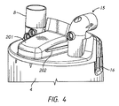
図2Aおよび2Bは、例示的実施形態による加湿装置1を示す。図2Bにおいては、さらなる詳細を示すためにいくつかの部分が除去されている。装置は、医療用チューブまたは導管3を加湿チャンバ4の出口15へ空気圧式に接続する回路コネクタ2を含む。図4に示されるとおり、出口15は、加湿チャンバ4がベースユニット5に設置されるときベースユニット5から離れるように角度がつけられた、実質的に水平な部分において終端し得る。導管3は、患者回路、すなわち加湿されたガスをユーザへ、例えば、患者インターフェイス(図示せず)を経て送達するように構成された患者回路の吸気肢であってもよい。加湿チャンバ4の入口8は加圧ガス源へ流体連通されるように構成される。これは、加湿装置1から取り外し可能であってもよいが、加湿装置1から離れて位置づけられてもその一体部分を形成してもよい。例えば、入口8は、ガスを入口8を通るよう駆動するベースユニット5内のまたはベースユニット5と関連するモータを取り付けたファンへ空気圧式に結合されてもよい。
2A and 2B show a humidifier 1 according to an exemplary embodiment. In FIG. 2B, some parts have been removed to show further details. The apparatus includes a
回路コネクタ2は、カプラ6を介したベースユニット5への電気的接続をさらに容易にする。カプラ6はベースユニット5と一体的に形成されてもよく、または個別の取り替え可能なモジュールまたはカートリッジであってもよい。モジュールを変更する機能が、異なる形態の加湿チャンバおよび/または回路コネクタの使用を可能にするために有利には使用され得る。加えてまたは代替的に、制御回路構成を含むことにより、モジュールが、加湿装置1の動作を変更するよう変えられてもよい。導管3は、システムの1つまたは複数のパラメータに関する信号の連通を電気的にまたは他の方法で容易にする導管および/またはセンサワイヤを通って流れるガスの加熱を提供する1つまたは複数の抵抗加熱ワイヤを含んでもよい。したがって、用語「電気的接続」は「空気圧式接続」と区別するために使用され、限定的であるように解釈されるべきではない。例えば、光ファイバーを介して光信号が伝えられてもよい。結果として、回路コネクタ2はより一般的に、導管3(およびセンサなどの任意の関連する周辺装置)をベースユニット5へ、例えばカプラ6を介して通信可能におよび/または電気的に接続してもよい。
The
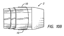
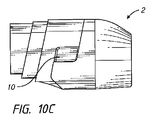
回路コネクタ2は、回路コネクタ2(およびしたがってまた導管3)が加湿チャンバ4から取り外されることを可能にするよう手動で押下され得る少なくとも1つのボタンまたはスイッチ10を含み得る。本明細書において明らかになるとおり、回路コネクタ2および加湿チャンバ4の出口15は、それらの間の接続について係止可能に係合されるようになり得、後で回路コネクタ2を加湿チャンバ4から係合解除可能とすることができるよう少なくとも1つのボタンまたはスイッチ10が使用される。任意の好適な接続が使用され得る。
The
ベースユニット5は、ユーザディスプレイおよび/または制御装置を取り付けるのに使用されてもよいパネル9をさらに含む。例えば、様々なダイアル、スイッチ、および他の入力手段がデバイスの動作を制御するために使用され得る。加えてまたは代替的に、タッチスクリーンディスプレイが使用されてもよい。ユーザディスプレイは、何らかのエラーもしくは誤作動を警告する、またはユーザの行動が必要な場合に入力を促すなどの、システムのパラメータを表示してもよい。タッチスクリーンディスプレイが使用される場合、同じディスプレイが、少なくとも部分的に、情報をユーザへ提示し、ユーザから入力を受信するために、使用されてもよい。
The
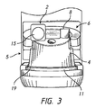
図3に示されるとおり、ベースユニット5は、加湿チャンバ4の内容を加熱するよう制御可能な方法で給電されるヒータープレート11を含む。より迅速な加熱を達成するために、加湿チャンバ4は高熱伝導性材料から作られるベースプレート19を含んでもよい。さらに、加湿チャンバ4のベースプレート19とヒータープレート11との間の良好な接続を確実にするために、2つの表面は互いに向かって偏向されてもよい。例えば、一実施形態によれば、縁12が加湿チャンバ4のベースプレート19からまたはその近くで外側に延在し、加湿チャンバ4がベースユニット5上を摺動するとベースユニット5の突出するリム13の下に受け入れられる。ヒータープレート11は、ヒータープレート11が加湿チャンバ4のベースプレート19内へ上向きに付勢されるようにばね式に取り付けられてもよく、縁12は突出するリム13に抗するよう作用する。
As shown in FIG. 3, the
図2Aを再び参照すると、ベースユニット5はばね付きのラッチバー14をさらに含む。加湿チャンバ4をベースユニット5と係合させるために、ラッチバー14は、第1に、縁12が突出するリム13の下に受け入れられ得るように押下される。これは、加湿チャンバ4のベースプレート19をラッチバー14上に位置づけ、加湿チャンバ4を下向きに、その後ベースユニット5の後方に向かって押すことにより都合よくは実施されてもよい。加湿チャンバ4がベースユニット5と完全に係合されると、ラッチバー14は、加湿チャンバ4のベースユニット5からの意図しない除去を防止するために持ち上げられかつ機械的ストッパとして機能し得る。加湿チャンバ4をベースユニット5から係合解除するためには、ラッチバー14が第1に押下されなければならず、その後加湿チャンバ4が、加湿チャンバ4のベースプレート19をヒータープレート11の表面にわたり、その後ラッチバー14上を摺動することにより、ベースユニット5から引き離されなければならない。図示のとおり、加湿チャンバ4は、加湿チャンバ4がベースユニット5から引き離されるときに、ユーザが加湿チャンバ4を把持するのをより容易にする把持部分16を含み得る。
Referring again to FIG. 2A, the
図4を参照すると、加湿チャンバ4の出口15は、少なくとも加湿チャンバ4から先端側にある出口15の端部において、加湿チャンバ4がベースユニット5上を摺動するまたはそこから滑り落ちるときに、加湿チャンバ4の移動方向に実質的に平行になるように方向づけられてもよい。装置をこのように構成することにより、回路コネクタ2、加湿チャンバ4、およびベースユニット5を、加湿チャンバ4をベースユニット5と係合しその後回路コネクタ2を加湿チャンバ4の出口15へ取り付けるか、または回路コネクタ2を加湿チャンバ4の出口15へ取り付け、その後加湿チャンバ4をベースユニット5と係合するかのいずれかにより組み立てることが可能になる。後者の組み立てオプションは、回路コネクタ2および出口15が係止可能に係合されるように構成され、このことは加湿チャンバ4がベースユニット5上を摺動する間回路コネクタ2が出口15から分離するのを防止することから、従うのがさらにより簡単になる。加えて、後者の組み立てオプションと同様に、導管3および加湿チャンバ4は、配送のために予め組み立てされてもよく、それにより組立プロセスから1ステップを除去する。組立ての順序と関係なく、導管3および/または回路コネクタ2とカプラ6および/またはベースユニット5との間の電気的接続または他の接続は、回路コネクタ2がカプラ6と結合する際になされ得る。
Referring to FIG. 4, the
同様に、分解は異なる順番で実施されてもよい。より詳細には、回路コネクタ2が第1に加湿チャンバ4の出口15から除去され、続いて加湿チャンバ4がベースユニット5から除去される。代替的に、回路コネクタ2が加湿チャンバ4の出口15へ依然として取り付けられているときに、加湿チャンバ4がベースユニット5から除去されてもよい。後者のオプションは、ベースユニット5からの消耗品の分解および廃棄の間の流体の漏れの可能性を減らすのに有利には役立ち得る。
Similarly, the decomposition may be performed in a different order. More specifically, the
案内特徴部
回路コネクタ2、加湿チャンバ4、およびベースユニット5のその組立体上への係合を容易にするために、様々な案内装置が、互いに対するその向きおよび/または位置を制御するために設けられてもよい。より詳細には、加湿チャンバ4が摺動されてベースユニット5およびカプラ6と係合するのを可能にするために、特に回路コネクタ2が出口15に取り付けられるときに、構成要素部品がすぐにかつ容易に整列させられるように、様々な配向特徴部が加湿チャンバ4および/またはカプラ6上に設けられてもよい。例えば、加湿チャンバ4は、回路コネクタ2もカプラ6と係合させられるように、ベースユニット5と完全に係合させられ得る。本明細書において以下に開示されるとおり、回路コネクタ2および/またはカプラ6は加えてまたは代替的に、回路コネクタ2が、回路コネクタ2および加湿チャンバ4のベースユニット5およびカプラ6への簡単な結合を可能にするよう適切に方向づけられた状態で、回路コネクタ2が加湿チャンバ4へ接続されることを確実にするのに役立つように配向特徴部を含んでもよい。
Guide Features To facilitate the engagement of the
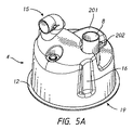
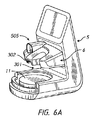
図5A〜5Fは加湿チャンバ4の例示的実施形態の様々な代替図である。図6A〜6Cはカプラ6の代替図である。図5A〜5Fに示されるとおり、加湿チャンバ4は、鼻部分201と案内羽根202とを含み得る。これらの特徴部は、カプラ6における輪郭形成された(contoured)凹部301およびスロット302とそれぞれ係合するように構成される(図6A〜6C参照)。
5A-5F are various alternative views of an exemplary embodiment of the
さらなる開示は、座標系であって、Z軸がヒータープレート11から垂直に延在し、Y軸が加湿チャンバ4とベースユニット5との係合の方向に整列し、X軸がZおよびY軸の両方に垂直である座標系に言及する。さらに、鼻部分201の幅はX軸に沿って画定され、鼻部分201の長さはY軸に沿って画定され、鼻部分201の高さはZ軸に沿って画定される。
A further disclosure is a coordinate system in which the Z axis extends vertically from the
一実施形態において、鼻部分201の幅は鼻部分201の第2端部でよりも第1端部で狭く、鼻部分201の第1端部は、第1に凹部301内に受け入れられるように構成されている。これは、鼻部分201が凹部301内に最初に受け入れられるようにするために、加湿チャンバ4のX軸に沿った(同様にZ軸を中心に回転する)位置に関するいくらかの公差を提供する。さらに、鼻部分201の広い方の第2端部は鼻部分201(およびしたがってまた加湿チャンバ4)のX軸に沿った(およびZ軸を中心として回転する)位置を、鼻部分201と凹部301との間の間隔または公差が減少され、それにより相対的移動の程度が減少するという点において、精緻化するよう機能してもよい。
In one embodiment, the width of the
図示の実施形態において、凹部301は、鼻部分201の傾斜した側壁が、対応しかつ同様に傾斜する凹部301の側壁に当接するように構成される。鼻部分201の側壁および凹部301の側壁をこのように構成することにより、加湿チャンバ4の位置は、X軸に沿ってだけでなくYおよび/またはZ軸を中心とする回転についても制御されるが、その理由は、鼻部分201の長さに沿った、およびまた鼻部分201の高さに沿った少なくとも2つの位置における鼻部分201のX軸に沿った移動が実質的に抑制されるからである。
In the illustrated embodiment, the
しかしながら、鼻部分201の側壁が凹部301の側壁と当接しない場合もこれらの利益のいくつかを達成することは可能である。例えば、鼻部分201が図示のとおりに構成されるが、凹部301の側壁がそれらの長さに沿って実質的に平行であり、鼻部分201のその第2端部での最大幅より大きい距離だけ間隔を空けて配される場合、構成は依然として鼻部分201の凹部301内への最初の挿入を支援し、Z軸を中心としたいくらかの回転移動は可能となり得るが、鼻部分201の第2端部での鼻部分201のX軸に沿った移動を少なくともかなり制限する。鼻部分201の側壁が実質的に平行であり、凹部301がY軸に沿ったその長さに沿って、その開口部から鼻部分201の幅と少なくとも同じ大きさの幅へ狭くなる場合も、同様の結果が達成される。
However, some of these benefits can also be achieved if the side wall of the
凹部301と組み合わされた鼻部分201は加えてまたは代替的に、加湿チャンバ4の最初の配置に対する少なくともZ軸に沿った公差を提供してもよい。さらに、特定の実施形態によると、鼻部分201および凹部301は協働して、Z軸に沿ったおよび/またはXおよび/またはY軸を中心とする回転についての加湿チャンバ4の位置を精緻化し得る。
The
この公差は、X方向における公差と同様の方法で提供される。図示のとおり、例えば図5Cにおいて、鼻部分201の高さは第2端部でよりも第1端部で低くなっており、高さはベースプレート19から計測される。図6Bに示されるとおり、凹部301は同様に輪郭形成され、それにより容易な最初の挿入を提供し、その後加湿チャンバ4のベースユニット5との完全な係合への引き続きの挿入に際してのZ軸に沿った位置の精緻化が続く。X軸に沿った幅方向の公差に関する説明と同様に、凹部301の下側の実質的に下方に向く反対側の壁は、その長さに沿って鼻部分201の上方に面する上側と当接しなくてもよい。例えば、一方または他方が、先に述べられたものと同様の欠点を有して、ヒータープレート11と実質的に平行に方向づけられてもよい。より詳細には、最初の挿入が容易にされ得る一方で、加湿チャンバ4のZ軸に沿った位置の精緻化の度合いは減少され得、ベースプレート19がヒータープレート11に平行になることを確実にするための制御性が低下し得る。
This tolerance is provided in a manner similar to the tolerance in the X direction. As shown in FIG. 5C, for example, the height of the
幾つかの実施形態において、案内羽根202のスロット302との係合は、ベースプレート19とヒータープレート11との突出するリム13を介した整列および係合の必要性を減らすのに十分な移動制限を提供する。いくつかの構成において、ベースユニット5は突出するリム13を含まなくてもよい。幾つかの実施形態において、鼻部分201は案内羽根202がない状態で設けられてもよい。しかしながら、加湿チャンバ4の少なくともZ軸に沿った位置付けの制御性を高めるためにおよび/またはヒータープレート11がベースプレート19に実質的に平行であることを確実にするために、少なくとも、ヒータープレート11がばね式に取り付けられた実施形態においては案内羽根202の使用が好ましい。反対に、案内羽根202は鼻部分201がない状態で設けられてもよいが、このような構成はあまり好ましいものではなく、その理由は鼻部分201は加湿チャンバ4の最初の位置決めをより容易に支援することができ、かつまた、位置を精緻化するためにその最初の粗い調節を行うことができ、案内羽根202が次いでZ軸に沿った加湿チャンバ4の位置をさらに精緻化するのに使用され、少なくともXおよびY軸を中心とした向きを制御する可能性があるからである。鼻部分201が省略される場合、案内羽根202は例えば、加湿チャンバ4から垂直に延在する実質的に剛性の取付具へ取り付けられてもよく、案内羽根202はそこから横方向に延在する。実質的に剛性の取付具は、実質的に平面的であってもよく、略T字型の断面を備える。しかしながら、強度および剛性を増大させるためには、取付具は、厚さを有するより大規模な要素を含んでもよいが、この厚さにより取付具がカプラ6と直接接触することは概してない。
In some embodiments, the engagement of the
例えば、図5Bに示されるとおり、案内羽根202は鼻部分201の第1端部へ完全に至るまでには延在しない。代わりに、それらは鼻部分201の第1端部から間隔を空けて配され、それにより鼻部分201と凹部301との間の最初の係合を、案内羽根202とスロット302との係合なしに可能にし、これは、加湿チャンバ4とベースユニット5との、2つの間の相対的位置が精緻化された後の引き続きの係合に際してのみ生じる。
For example, as shown in FIG. 5B, the
明らかになるとおり、代替的案内手段が代用され得る。例えば、加湿チャンバ4の輪郭形成された凹部がカプラ6の鼻部分または突起部を受け入れるように、鼻部分201が輪郭形成された凹部の形態であってもよく、逆もまた同様である。同様に案内羽根202はカプラ6上の羽根または他の突起部を受け入れる溝で置換されてもよい。同じ機能を果たす他の配置構成も使用され得る。
As will become apparent, alternative guiding means can be substituted. For example, the
また図7から明らかかつ図10A、10D、および10Eにおいてより明らかに図示されるとおり、回路コネクタ2は、出口15の実質的に垂直部分を収容するように構成されたカットアウト403を含み得る。この場合も、完全な挿入は正しい整列でのみ可能であることから、これは、回路コネクタ2が出口15の端部へ挿入される際に正しく方向づけられることを確実にするのに役立つ。さらに、この配置構成はより強い結合をもたらし、以下に記載の電気的接続を可能にする。この場合も、カットアウト403の少なくとも最初の部分は、出口15の垂直部分を受け入れるカットアウト403の第1部分が出口15より広く、必要とされる最初の整列についていくらかの公差を提供するように角度がつけられるか湾曲され得る。しかしながら、出口15が略円形の断面である場合、いくらかの公差が出口15の円形状により本来的にもたらされるため、これは必要とされないこともある。
Also as apparent from FIG. 7 and more clearly illustrated in FIGS. 10A, 10D, and 10E, the
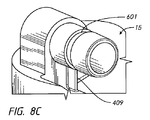
図8Aおよび8Cを参照すると、回路コネクタ2は、加えてまたは代替的に、出口15上の同様に角度がつけられた突起部409を受け入れる角度がつけられたカットアウト408を含んでもよい。この場合も、これは回路コネクタ2および出口15の互いに対する向きを確立および固定するよう機能する。
With reference to FIGS. 8A and 8C, the
加えてまたは代替的に、案内手段がヒータープレート11および/または加湿チャンバ4のベースプレート19に組み込まれてもよい。例えば、ヒータープレート11の隆起部が加湿チャンバ4のベースプレート19の溝の中に受け入れられるように構成されてもよく、逆もまた同様である。
In addition or alternatively, guide means may be incorporated into the
回路コネクタ
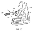
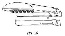
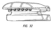
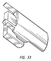
回路コネクタ2の第1実施形態が図2A、2B、6C、および7に示される。回路コネクタ2の第1端部(図2B参照)は、呼吸チューブすなわち導管501の端部を受け入れるおよび空気圧式にシールするように構成される(図6C参照)。
Circuit Connector A first embodiment of
回路コネクタ2は本体502と延長部分504とを含んでもよい。組み立てられると連続的な流路を提供するように、本体502の内部は導管501を出口15の水平な部分へ接続するチャネルを画定する。シール(例えばOリング、二重Oリング、またはリップシール)が、送達されているガスの漏れを防止するために、本体502の内部と出口15の外部との間の接触面の間に設けられてもよい。
The
カプラ6は延長部分504を受け入れかつ覆うシュラウド505を含む状態で図示の。これは、液体が漏れた場合その液体が回路コネクタ2の電気構成要素と接触するようになる可能性を減らすまたは除去するのに役立ってもよく、かつまた結合を強化し硬くするよう機能する。さらに、シュラウド505は、回路コネクタ2を加湿チャンバ4の出口15と係合させる、および/またはベースユニット5と係合させるのを支援し得る。より詳細には、シュラウド505は、回路コネクタ2がどこに位置づけられるべきかについての視覚的な表示を提供する。さらに、シュラウド505は回路コネクタ2の位置の上にいくらかの物理的制御を提供し得る。例えば、図示の実施形態において、少なくとも回路コネクタ2の延長部分504は、ヒータープレート11に対向するシュラウド505の壁の一部に接するように受け入れられる。これは、ヒータープレート11をシュラウド505に向かって付勢するためにヒータープレート11がばね式である場合に特に起こり得る。したがって、回路コネクタ2の少なくとも高さ(すなわちZ軸に沿った)は制御され得る。シュラウド505が湾曲した反対側の壁を備えることで、回路コネクタ2がシュラウド505により形成された円弧の中心に向って付勢されるため、回路コネクタ2のX軸に沿った位置決めを支援することができる。シュラウド505の物理的位置決め機能は、回路コネクタ2の位置の上限だけでなくその実際の位置を制御するためにシュラウド505に少なくとも部分的に回路コネクタ2を取り囲む壁を画定させることにより、なおさらに向上される。
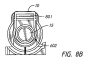
図8A〜8Cは回路コネクタ2と出口15との間の係止可能であるが取り外し可能な結合の実施形態を図示する。回路コネクタ2は、例えば、回路コネクタ2を出口15から除去することを可能にするために例えば親指または他の指により手動で駆動し得るボタン10を含む。ボタン10は弾性的に伸縮自在の(resiliently elastic)材料から作製され、出口15の外壁に形成された凹部601内に受け入れられるように構成された部分を有する。ボタン10の押下は、ボタン10の係合部分を凹部601から係合解除する。図8Dおよび8Eは、ボタン10が実質的に剛性の材料から作製されるがばね式に取り付けられてもよい代替的実施形態を図示する。ボタン10の押下はばねに抗して作用し、ボタン10の係合部分602を出口15の外壁の凹部から係合解除する。
8A-8C illustrate an embodiment of a lockable but removable connection between the
図9Aおよび9Bは、ボタン10またはその少なくとも係合部分602が弾性的に伸縮自在であり、それにより少なくともボタン10の一部が変形して係合部分602を出口15の凹部601から係合解除する、代替的実施形態を図示する。
9A and 9B show that the
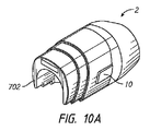
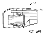
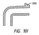
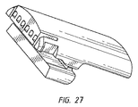
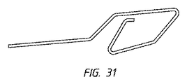
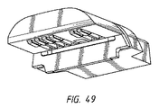
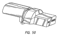
図10A〜10Hは回路コネクタ2の代替的実施形態を図示する。図10F〜10Hにおいて、さらなる詳細を示すために回路コネクタ2の一部が除去されている。この実施形態によると、ボタン10が回路コネクタ2の側部に位置づけられるが、その理由はこれが回路コネクタ2を出口15から分離しようとするときにユーザにとって自然な接触ポイントに置かれるのに便利であり得るためである。ボタン10は伸縮自在(elastically)に変形可能なリング701と一体化されるかそれへ動作可能に結合される。ボタン10の押下がリング701を出口15の上方外側表面および下方外側表面の少なくとも1つに形成された凹部から係合解除し、回路コネクタ2が除去されることを可能にする。図10A〜10Hはまた、電気的接続部または他の接続部を収容するための空洞702を示す。凹部の代替物として、図10Iにおける断面図に示されるとおり出口15において突起部705が使用されてもよい。これは、本明細書において開示されるこのおよび他の実施形態に当てはまる。いくつかのそのような実施形態において、回路コネクタ2が出口15へ結合されるとき、リング701の上部は突起部705の後ろ(または突起部705よりベースユニット5の近くに)にある。回路コネクタ2を出口15から係合解除するためには、リング701の上部が突起部705のレベルより高く上昇し次いで回路コネクタ2が出口15から除去され得るように、ボタン10がリング701を変形させるために押される。電気端子がエッジカード901の形態であるさらなる実施形態が図10Jおよび10Kにおいて示される。さらに図示されるのは、Oリングなどのシールを受け入れられるように構成された溝902である。
10A-10H illustrate an alternative embodiment of the
電気的接続部
例示的電気的接続部801が図8Aおよび8Bにおいて示される。電気的接続部は、それらが空気圧式接続部を越えて延在し、図6Dに示されるとおりカプラ6上の協働コネクタ802へ電気的におよび/または通信可能に結合するように、回路コネクタ2の延長部分504に設けられてもよい。図8Aおよび8Bに示されるとおり、電気的接続部および他の接続部はブレード接続部により形成されてもよく、ブレード接続部はそれへ接続するための接点を収容するカプラ6におけるそれぞれの凹部において受け入れられる。ピンなどの他のコネクタが代替的に使用されてもよいが、ブレード接続部が、凹部でのブレードの正確な相対的位置付けにおけるいくらかの公差を提供するには有利である。図示の実施形態においては、いくらかの垂直の公差が提供される。
Electrical Connection An exemplary
代替的実施形態によると、電気接点は、ばね式ピンであってそれらがハウジングから突出する程度を変更することを可能にする通路内に収容されたばね式ピンを含む1つまたは複数のポゴピンまたはばねピン接点を含み、それにより回路コネクタ2およびカプラ6のピンの軸に沿った相対的位置における公差を提供する。さらに、ピンが押されようになる機能は、協働または嵌合コネクタをより容易に収容するアパーチャへのピンの挿入を生じさせ得る。
According to an alternative embodiment, the electrical contacts are spring-loaded pins and one or more pogo pins or springs comprising spring-loaded pins housed in passages that allow the degree to which they protrude from the housing to be altered It includes pin contacts, thereby providing tolerances in relative positions along the axis of the pins of
別の代替的実施形態によると、電気的接続部はエッジカードコネクタすなわちカードエッジコネクタを含み、コネクタの第1部分は、プリント回路基板上に設けられコネクタの第2部分の1つまたは複数のピンと接触するように構成された1つまたは複数の導電性トラックを有する。 According to another alternative embodiment, the electrical connection comprises an edge card connector or card edge connector, the first portion of the connector being provided on the printed circuit board and one or more pins of the second portion of the connector. Having one or more conductive tracks configured to contact.
代替的実施形態
図11Aは、加湿チャンバ4の出口15と係合された回路コネクタ2の代替実施形態の断面図である。この実施形態において、回路コネクタ2は、回路コネクタ2の少なくとも一部が出口15の内側に受け入れられるように雄接続部を有する。Oリング1005または他のシールが雄部分と出口15の内側壁との間をシールするために使用される。
Alternative Embodiment FIG. 11A is a cross-sectional view of an alternative embodiment of the
図11Bは図11Aのものと同様の図を示すが、出口15が回路コネクタ2の入口の内側壁と嵌合する雄部分として構成されるように修正されている。この場合も、Oリング1005または他のシールが漏れの可能性を減らすまたは除去するために使用されてもよい。
FIG. 11B shows a view similar to that of FIG. 11A, but modified so that the
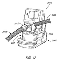
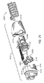
ここで図12を参照すると、加湿システム2000が示されている。加湿システム2000は任意の好適な構成であってよい。加湿システム2000は、持続的、可変、もしくはバイレベル気道陽圧(PAP)または他の任意のタイプの呼吸療法のための加熱および/または加湿されたガスを供給するための他の構成要素と共に使用されてもよい。これは例えば腹腔鏡手術などの手術用途のためのデバイスと共に使用されてもよい。
Referring now to FIG. 12, a
図示の加湿システム2000は、加湿チャンバ2004を受け入れるベース2002を含む。供給導管2006および送達用導管2008が加湿チャンバ2004へ接続されてもよい。供給導管2006は加湿チャンバ2004へ加湿されるガス流を送達してもよい。送達用導管2008は、ガス流がチャンバ2004内で加湿された後、ユーザまたは患者へガス流を送達してもよい。
The illustrated
いくつかの構成において、ベース2002は供給導管2006および送達用導管2008の(例えば吸気肢)一方または両方への電気的接続を含む。図示の構成において、ベース2002はカートリッジまたはカプラ2010を含む。カートリッジまたはカプラ2010はベース2002と一体的に形成されてもよく、または個別の、取り替え可能なモジュールまたはカートリッジであってもよい。導管2006、2008の一方または両方は1つまたは複数のワイヤを含み得る。ワイヤは、導管壁および/またはガス流の加熱をもたらす1つまたは複数の抵抗加熱ワイヤを含んでもよい。ワイヤは、システム2000の1つまたは複数のパラメータに関する信号を伝えるのを容易にする1つまたは複数のセンサワイヤを含んでもよい。したがって、用語「電気的接続」はその最も広い意味で使用され、例えば光ファイバーなどを介した光信号を含むべきであるがこれに限定されない。
In some configurations,
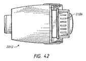
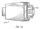
図示の送達用導管2008は、コネクタ2012を含む。コネクタ2012は導管2008とカートリッジ2010との間の電気的接続を容易にする。コネクタ2012はまた導管2008とチャンバ2004との間の空気圧式接続を容易にする。したがって、コネクタ2012は、ベース2002と導管2008との間の(カートリッジ2010を通じた)電気的接続およびチャンバ2004と導管2008との間の空気圧式接続の両方を容易にする。
The illustrated
図示の構成におけるコネクタ2012は水平方向(すなわちチャンバ2004のベース2002内または上への挿入方向に平行な方向)に接続するよう構築される。コネクタ2012は、カートリッジ2010へ水平方向へ電気的に接続するよう構築される。コネクタ2012は、チャンバ2004へ水平方向に空気圧式に接続されるよう構築される。コネクタ2012は、カートリッジ2010およびチャンバ2004の両方へ同じ水平方向に接続するよう構築される。
The
カートリッジまたはカプラ
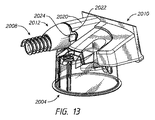
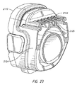
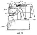
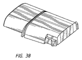
カートリッジまたはカプラ2010、チャンバ2004、およびコネクタ2012間の接続部は図13〜16においてより良好に示される。図示のとおり、カートリッジ2010は、カートリッジ2010の電気コネクタ(例えば、図16に示される電気的接合部2034)を覆うフード部分2020を含み得る。フード部分2020はベース2002の前方に略水平方向に延在してもよい。
Cartridge or Coupler The connections between the cartridge or
フード部分2020は、垂直に延在する部分に沿った凹部2022を含んでもよい。凹部2022は、解放ボタン2024を含むコネクタ2012の一部を受け入れるように大きさを決められ、位置づけられ、構成される。図示の構成において、フード2020の少なくとも一部は、(カートリッジ2010へ接続されるとき)コネクタ2012の上部に沿って、コネクタ2012上の解放ボタン2024の位置に対してベース2002からさらに延在する。他の構成も可能である。
The
インサートブロック
図14を参照すると、図示の構成において、インサートブロック2030はコネクタ2012とカートリッジ2010との間の電気的接続を容易にし得る。いくつかの構成において、水滴または他の湿度がコネクタ2012に存在し得る。インサートブロック2030は、コネクタ2012とカートリッジ2010との間の望ましい電気的接続を容易にする一方で、カートリッジ2010を水または他の湿度から隔離するのに役立つ。
Insert Block Referring to FIG. 14, in the illustrated configuration, the
インサートブロック2030はコネクタ2012へまたはカートリッジ2010へ取り付けられてもよい。いくつかの構成においては、インサートブロック2030はコネクタ2012にもカートリッジ2010にも取り付けられない。図示の構成において、インサートブロック2030はカートリッジ2010へ取り付けられている。インサートブロック2030をカートリッジ2010へ取り付けることにより、導管2008などの交換の間にインサートブロック2030が誤った場所に置かれるようになる可能性が大幅に減少する。インサートブロック2030をコネクタ2012へ取り付けないことにより、導管2008の交換が単純化され、各使用の後に導管2008と共に廃棄されるであろうインサートブロック2030と比べると廃棄物が少ない。
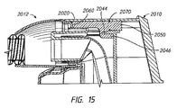
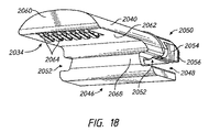
図17〜18を参照すると、インサートブロック2030は第1電気的接合部2032と第2電気的接合部2034とを有する。第1電気的接合部2032は、カートリッジ2010の電気コネクタと係合するように大きさを決められ、位置づけられ、構成される。第2電気的接合部2034は、コネクタ2012の電気接点2036(図14参照)と係合するように大きさを決められ、位置づけられ、構成される。第1電気的接合部2032および第2電気的接合部2034は任意の好適な方法で結合され得る。有利には、インサートブロック2030は、第1電気的接合部2032とカートリッジ2010の電気コネクタとの間の略水平な接続を第2電気的接合部2034とコネクタ2012の電気接点2036との間の略垂直の接続へ変換する。
Referring to FIGS. 17 to 18, the
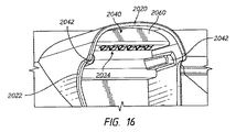
インサートブロック2030は本体2040を含む。本体2040はフード2020内に受け入れられるように大きさを決められ、構成される。いくつかの構成において、本体2040はフード2020内に保持されるように大きさを決められ、構成される。いくつかの構成において、フード2020は1つまたは複数の整列特徴部2042を含む。図示の構成において、フード2020の整列特徴部2042はレール2042を含む。レール2042は任意の好適な構成を有してよい。図示の構成において、2つのレール2042はフード2020の直径方向に対向する側に互いに整列される。さらに、図15において図示のとおり、示されたカートリッジ2010はまたフランジ2044を含む。フランジ2044はレール2042と一体的に形成されてもよく、または、レール2042から個別の特徴部であってもよい。フランジ2044は略水平に延在し、コネクタ2012を受け入れる空洞の後方壁から前方に突出する。フランジ2044はフード2020により覆い隠される。いくつかの構成において、フランジ2044は、先端部が基端部と比べて厚さが薄い段差が付けられた構成を有し、基端部が先端部より空洞の後方壁に近い。
本体2040は取付ボス2046を含む。凹部2048が、取付ボス2046と第1電気的接合部2032へ延在する本体2040の別の部分との間に画定されてもよい。凹部2048は、フランジ2044の少なくとも一部を受け入れるように大きさを決められ、構成されてもよい。特に、本体2040の係合部分2050は取付ボス2044から凹部2048だけ間隔を空けて配されてもよい。他の構成も可能である。
The
取付ボス2044はチャネル2052を含み得る。チャネル2052は、レール2042を受け入れるように大きさを決められ、位置づけられ、構成されてもよい。チャネル2052は、インサートブロック2030がフード2020内に固定されたときレール2042のかなりの部分が取付ボス2044を越えて露出するように、レール2042より長さが短くてもよい。
The mounting
本体2040の係合部分2050は1つまたは複数の保持要素2054を含んでもよい。図示の構成において、1つまたは複数の保持要素2054は各々偏向可能なタブを含んでもよい。少なくとも1つの偏向可能なタブ2054は、本体2040の反対側の各側部に位置づけられてもよい。図示の構成において、本体2040は本体2040の各側面上に配置された偏向可能なタブ2054を有する。
The
タブ2054は捕捉要素2056を含み得る。捕捉要素2056は本体2040から離れるように横方向に延在してもよい。いくつかの構成において、捕捉要素2056は偏向可能なタブ2054の少なくとも一部を本体2040から離す凹部から略垂直に延在してもよい。いくつかの構成において、捕捉要素2056を含む偏向可能なタブ2054の基端部は、インサートブロック2030のフード2020内への挿入の間に本体2040に向かって内側へのタブ2054の偏向を促進するように成形されてもよい。例えば、捕捉要素2056の基端面は上から見ると先細になっていてもよい。
本体2040は先端部2060を含む。先端部2060の近くで、本体2040の上面は、フード2020の内側面に一致するように成形されてもよい。図示の構成においては両方とも湾曲している。
The
本体2040の先端部2060はフード2020内で凹んでいてもよい。図15に示されるとおり、先端部2060は、コネクタ2012の隣接する端部を補完するように成形され、構成されてもよい。例えば、図示の構成において、本体2040の先端部2060はわずかに先細になっていてもよい。
The
接触面2062が先端部2060と取付ボス2046との間に位置づけられてもよい。図示の構成において、接触面2062は下を向いている。いくつかの構成において、接触面2062は略平面である。
接触面は、1つまたは複数の開口であってそれを通って接触端子2064が延在し得る1つまたは複数の開口を含む。接触端子2064は第2電気的接合部2034の少なくとも一部を画定し得る。接触端子2064は任意の好適な構成を有してもよい。
The contact surface includes one or more openings through which the
いくつかの構成において、接触端子2064は水が付着し得る表面を最小化するまたは減らすように構成されているばね付きの端子である。いくつかの構成において、接触端子2064は、拭き取りまたは除塵の間に布が付き得る表面を最小化するまたは減らすように構成されたばね付きの端子である。弛緩した状態において、接触端子2064は有利には接触面2062を越えて下向きに突出する。圧縮されると、接触端子2064は本体2040内へ少なくとも部分的に偏向され得る。
In some configurations, the
図17を参照すると、いくつかの構成において、本体2040は包囲溝2066を含み得る。溝2066は取付ボス2046を係合部分2050へ接続する柱2068の後方に位置づけられてもよい。いくつかの構成において、溝2066はシーリング構成要素2070を受け入れてもよい。いくつかのそのような構成において、シーリング構成要素2070はシール、Oリングなどであってもよい。いくつかの構成においては、溝2066もシーリング構成要素2070も存在しない。
Referring to FIG. 17, in some configurations, the
図15を参照すると、インサートブロック2030はフック2020に挿入されてもよい。挿入の間、レール2042はチャネル2052内に位置づけられる。インサートブロック2030は、フランジ2044が凹部2048内に受け入れられるまで近接して摺動される。存在する場合、シーリング構成要素2070は係合部分2050とカートリッジ2010の囲む部分との間で圧縮され得る。挿入の間、フード2020の内側面上の特徴部は、捕捉要素2056が内側面上の特徴部の基端付近に来るまでタブ2054を本体2040に向かって内側に偏向させ得、ここで捕捉要素2056は内側面上の特徴部の近くに位置づけられ、タブ2054が弛緩した状態へ戻り得る。インサートブロック2030をフード202内に固定するための任意の好適な構成が使用され得る。適切な位置へ挿入されそこに固定されると、第1電気的接合部2032(例えば、レセプタクル)はカートリッジ2010の電気コネクタの対応する要素(例えば、ピン)と電気的に接触してもよい。インサートブロック2030が設置されると、第2電気的接合部2034(例えば、端子2064)は、乾燥、拭き取り、除塵などのために容易にアクセスされ得る。加えて、端子2064の構成を原因として、端子2064などへ施されるコーティング、水および他の液体が端子2064上に残ることもそれに付着することもありそうにない。
Referring to FIG. 15, the
コネクタ
ここで図19〜24を参照すると、コネクタ2012がさらに詳細に説明される。コネクタ2012は導管2008の端部に任意の好適な方法で固定され得る。
Connector Referring now to FIGS. 19-24,
図24を参照すると、コネクタ2012は概して内部プラグ2100を含む。導管2008は、図示の内部プラグ2100上に螺合され、外側被覆または他の任意の好適な技術を使用してそこへ固定されてもよい。いくつかの構成において、シール2102が内部プラグ2100の外側表面へ位置づけられてもよい。シール2102は、チャンバ2004のポートの内側表面と空気圧式シールを形成するのに役立つように使用されてもよい。
Referring to FIG. 24, the
内部プラグ2100はまたプリント回路基板2104を担持する。プリント回路基板2104は接触パッド2106を含み得る。接触パッド2106は任意の好適な構成を有してもよい。接触パッド2106は、インサートブロック2030の第2電気的接合部2034の端子2064と接触するように大きさを決められ、位置づけられ、構成される。図示の構成において、互いに等しい間隔を空けて配された6つの接触パッド2106がある。接触パッド2106は、水滴の存在に起因するショートの可能性を減らすために間隔を空けて配され得る。
The
ここで図42〜44を参照すると、コネクタ2012の例示的実施形態は、様々な設計に従い大きさを決められ、位置づけられ、間隔を空けて配される接触パッド2106を有し得る。図42は導管コネクタ2012の例示的実施形態を示し、均一に大きさを決められ、間隔を空けて配された接触パッド2106を示し、ここで、接触パッド2106はヒーターパッド、識別パッド、センサパッド、センサパッド、識別パッド、ヒーターパッド(これはHISSIHと示され得る)の順で位置づけられ、各々対応するワイヤに接続するために適合される。図43は導管コネクタ2012の例示的実施形態を示し、同様にHISSIHの順で均一に間隔を空けて配されているが、ヒーターワイヤ接続が識別およびセンサワイヤ接続より先に作られ、後で絶たれることを確実にするのに役立ち得る相対的に長いヒーターパッドを備える接触パッド2106を示す。図44は、接触パッド2106が同様に相対的に長いヒーターパッドを有するが、SSIIHHの順で上から下へ不均一に間隔を空けて配されたパッド(これはセンサパッドとヒーターパッドとの間のスペースを増大させる)を備える導管コネクタ2012の例示的実施形態を示す。一実施形態において、(図44において示される上の)第1センサパッドは、正(positive)センサワイヤへの接続のために適合され、第2センサパッドは負(negative)センサワイヤへの接続のために適合され、このことは正センサパッドとヒーターパッドとの間のスペースを最大化するのに役立つ。また、図45を参照すると、コネクタ2012の実施形態は上から下へSSIIHHの順で、相対的に長いヒーターパッドおよびヒーターパッドと他のパッドとの間の間隙を備える接触パッド2106を有し、この場合もヒーターパッドとセンサパッドとの間のスペースを最大化するのに役立つ。
Referring now to FIGS. 42-44, an exemplary embodiment of the
図48はカートリッジ2010の代替実施形態の一部を示し、フード部分2020の下に電気的接合部または接点2034を備えるインサートブロック2030を示す。この実施形態において、電気接点2034は図47の接触パッド2106の間隔に対応する間隔を有し、特に、ヒーターパッドに対応する接点と識別およびセンサパッドに対応する接点との間の間隙を有する。図49および50は、図48に示されるインサートブロック2030の代替実施形態の追加的な図を提供する。
FIG. 48 shows a portion of an alternative embodiment of the
図19〜24を再び参照すると、内部プラグ2100は、前カバー2110および後カバー2112内に画定される空洞内に保持され得る。前カバー2110および後カバー2112は互いに結合されるか、カバー2110、2112内に内部プラグ2100を全体として囲むために内部プラグ2100へ結合され得る。図示の構成において、後カバー2112は内部プラグ2100の一部および前カバー2110へクリップで留まり、前カバー2110も内部プラグ2100の一部へクリップで留まる。
Referring again to FIGS. 19-24, the
いくつかの構成において、前カバー2110および後カバー2112のうちの一方の少なくとも一部で2つのカバー2110、2112の他方の対応する部分を覆うようにすることにより、前カバー2110と後カバー2112との間の縫い目は覆い隠される。図示の構成において、前カバー2110は凹部2114であってその上を後カバー2112の縁2116が滑動する凹部2114を含む。したがって、縁2116は2つのカバー2110、2112間の縫い目を覆い隠し、2つのカバー2110、2112間の当接関係は水がコネクタ2012に浸透する可能性を減らす。
In some configurations, at least a portion of one of the
図示の構成において、係止リング2118が前カバー2110と内部プラグ2100との間に固定され得る。係止リング2118は解放ボタン2024を含む。解放ボタン2024は、前カバー2110および/または後方カバー2112に設けられた開口部2120を通って突出する。係止リング2118はチャンバ2004のポートへラッチするように構成され、係止リング2118は解放ボタン2024を互いに向かって圧迫することにより偏向されることができ、これにより係止リング2118(およびしたがってコネクタ2012)のチャンバ2004のポートからの除去が可能となる。
In the illustrated configuration, a
図19〜22を再び参照すると、図示の前カバー2110は図24に示される構成とわずかに異なる構成を有する。図19〜22において示されるとおり、前カバー2110の先端部2120は傾斜面2122を有してもよい。傾斜面2122は、前カバー2110の底部よりさらに先端側に延在する前カバー2110の上部に由来し得る。いくつかの構成において、傾斜面2122は略平面である。いくつかの構成において、傾斜面2122は曲線をなしていてもよい。他の構成も可能である。
Referring again to FIGS. 19-22, the
図19、21、および23を参照すると、プリント回路基板2104は前カバー2110により支持され得る。図示の構成において、前カバー2110は外側表面2124に全体として囲まれ得る支持体領域2125を包含する。支持体領域2125はプリント回路基板2104の基礎をなし得る。コネクタ2012の接続および使用の間のプリント回路基板2104の屈曲または偏向の可能性を減らすために、支持体領域2125はプリント回路基板2104へ支持を提供し得る。図示の構成において(図23参照)、支持体領域は1つまたは複数のリブなどを含んでもよい。図示の構成において、支持体領域は、プリント回路基板2104を全体として囲むリムの周りに形成されるレッジを含む。図示のレッジは、プリント回路基板2104が凹んでいるか前カバー2110の囲む部分と同一平面であるように凹んでいる。1つまたは複数のリブがプリント回路基板2104のより中央の部分の下に延在してもよく、プリント回路基板2104の少なくとも中央部分に対する支持体を画定することができる。任意の数のリブが使用されてもよい。いくつかの構成において、他の形態の支持体(ボス、平坦部など)が使用されてもよい。いくつかの構成において、中央支持体は使用されない。
With reference to FIGS. 19, 21, and 23, the printed
図22を参照すると、前カバー2110はまた、少なくとも1つのチャネル2126を含む。図示の構成において、前カバー2110は2つのチャネル2126を含む。図示のチャネル2126は、略直径方向に反対側にある。チャネル2126はフード2020のレール2042と整列しそれを受け入れる。かくして、チャネル2126は、カートリッジ2010との結合の間に、コネクタ2012を整列させるのに役立ち得る。チャネル2126およびレール2042はまた、カートリッジ2010に対するコネクタ2012の、この2つが互いに結合されるときの、垂直移動(例えば、上下)、ねじれ(例えば内腔の軸に対する回転)および偏揺れ(例えば内腔の軸に垂直な軸に対する回転)に抵抗するのに役立ちする。
With reference to FIG. 22, the
再び図21を参照すると、前カバー2110は細長い窪み2128を含む。細長い窪み2128は前カバー2110の少なくとも上部の上に延在する。図示の構成において、細長い窪み2128はプリント回路基板2104の幅と少なくとも同じ大きさの横方向の広がりを有する(図20参照)。細長い窪み2128は、コネクタ2012上に漏れ得る液体をプリント回路基板2104から離れるように逸らすのに役立つ。細長い窪み2128はしたがってプリント回路基板2104の基端側であり、細長い窪み2128とプリント回路基板2104との間に少なくとも縁が画定されるように、前カバー2110内へ凹んでいてもよい。他の構成も可能である。
Referring again to FIG. 21, the
図21を参照すると、内部プラグ2100は内腔2130を画定する。内腔2130は導管2008と流体連通している。内腔2130は先端部2132を有する。先端部2132は非正規の(non−normal)構成を有する。換言すると、先端部2132は内腔2130の軸に対して単純に直角にされ(squared off)ない。いくつかの構成において、先端部2132は、それが挿入される加湿チャンバ2004のポートの内側形状を補完するように構成される。いくつかの構成において、内腔2130の先端部2132は、凝縮液が加湿チャンバ2004へ戻るよう排出される機能を高めるために、傾斜しかつポートの中へ可能な限り延在する。これは図15において最も明らかに示される。
Referring to FIG. 21, the
内腔2130の先端部2132は傾斜構成を有する。図示の構成において、内腔2130の先端部2132は、前カバー2110の傾斜面2122に対して異なる傾きで傾斜する。内腔2130の上部は内腔2130の底部に対して先端側にさらに突出する。さらに、内腔2130の上部は前カバー2110の傾斜面2122の最前方部分の前方へ突出する。内腔2130の上部は前カバー2110のいずれの部分よりもさらに先端側に突出する。いくつかの構成において、前カバー2110は内腔2130の底部の先端側に突出するが、内腔2130の上部は前カバー2110の上部よりさらに先端側に突出する。
The
いくつかの構成において、凹部角度Rが画定されてもよい。凹部角度Rは前カバー2110の上部と内腔2130の上部との間の側部から見たときの角度であってもよい。凹部角度Rはいくつかの構成においては18度であってもよい。凹部角度Rが18度より大きい場合、および、コネクタ2012が逆さまで(すなわち、プリント回路基板2104が水平で、接触パッド2106が床に面する)、凝縮液が導管2008から排出されるとき、プリント回路基板2104上に滴り落ちる可能性が大幅に減少するか除去されると考えられる。
In some configurations, a recess angle R may be defined. The recess angle R may be an angle when viewed from the side between the upper portion of the
図45および46を参照すると、コネクタ2012の代替実施形態において、外側支持体表面2124は外に向かって広がっていてもよい、すなわち、細長い窪み2128によってよりも先端部2120で広くなっている。この広がりは、コネクタ2012のフード2020の下への挿入の間に、チャネル2126がレール2042と適切に垂直に整列することを確実にするのに役立つ。
With reference to FIGS. 45 and 46, in an alternative embodiment of
図25を参照すると、チャンバ2004はポート2138を含む。ポート2138は開口部2140において終端する。図示のとおり、内腔2130の先端部2132は、プリント回路基板2104がインサートブロック2030の端子2064との接触に近づく時点で十分ポート2138内にある。かくして、図示の構成において、カートリッジ2010およびポート2138からのコネクタ2012の分離の間に、プリント回路基板2104とインサートブロック2030との間の電気的接続は、内腔2130とポート2138との間の空気圧式接続が絶たれる前に絶たれる。換言すると、電気的接続は空気圧式接続の前に絶たれる。同様に、コネクタ2012とカートリッジ2010およびポート2138との結合の際、空気圧式接続は電気的接続より前に確立される。より詳細には、内腔2130およびポート2138は、端子2064がプリント回路基板2104のパッド2106と接触する前に嵌合する。
Referring to FIG. 25,
特定の実施形態および例が本明細書において開示されたが、発明性のある主題は、具体的に開示された実施形態を越えて、他の代替的実施形態および/または使用へ、ならびにその修正形態および均等物にわたる。したがって、本明細書に添付される特許請求の範囲または実施形態は、本明細書において説明される特定の実施形態のいずれによっても限定されない。例えば、本明細書において開示されたいずれの方法またはプロセスにおいても、方法またはプロセスの行為または動作は任意の好適な順序で実施されることができ、いずれの特定の開示された順序にも必ずしも限定されない。様々な動作が、特定の実施形態を理解するのに役立ち得る方法で、複数の別個の動作として次々に説明され得るが、しかしながら、説明の順序は、これらの動作が順序に依存するものであることを暗示すると解釈されるべきではない。加えて、本明細書において説明されたいくつかの構造は、一体化された構成要素としても個別の構成要素としても実現され得る。様々な実施形態を比較する目的で、これらの実施形態の特定の態様および利点が説明されている。全てのそのような態様または利点が全ての特定の実施形態によって達成される必要はない。したがって、例えば、様々な実施形態が、1つの利点または一群の利点を、本明細書において同様に教示または提案され得る他の態様または利点を必ずしも達成せずに、本明細書において教示されるとおり達成または最適化する方法で実施されてもよい。 While specific embodiments and examples have been disclosed herein, the inventive subject matter extends beyond the specifically disclosed embodiments to other alternative embodiments and / or uses and modifications thereof. Spans forms and equivalents. Accordingly, the claims or embodiments appended hereto are not limited by any of the specific embodiments described herein. For example, in any method or process disclosed herein, the acts or actions of the method or process can be implemented in any suitable order and are not necessarily limited to any particular disclosed order. Not. The various operations may be described in turn as a plurality of separate operations in a manner that can help understand a particular embodiment, however, the order of description is such that these operations are order dependent. Should not be interpreted as implying. In addition, some of the structures described herein can be implemented as integrated components or as individual components. For purposes of comparing various embodiments, certain aspects and advantages of these embodiments have been described. Not all such aspects or advantages need to be achieved by all specific embodiments. Thus, for example, various embodiments are as taught herein, without necessarily achieving one advantage or group of benefits, other aspects or advantages that may also be taught or suggested herein. It may be implemented in a manner that is achieved or optimized.
多くの変形形態および修正形態が本明細書において説明された実施形態に対して作られ得るが、それらの要素は他の許容可能な例の中でもとりわけのものであると理解されるものであることが強調されなければならない。全てのそのような修正形態および変形形態は、本明細書において本開示の範囲内に含まれることを意図され、以下の特許請求の範囲により保護される。さらに、前述の開示におけるいずれのものも、任意の特定の構成要素、特徴または加工工程が必要または必須であると暗示することを意図するものではない。 Many variations and modifications may be made to the embodiments described herein, but those elements should be understood to be among other acceptable examples. Must be stressed. All such modifications and variations are intended to be included herein within the scope of this disclosure and are protected by the following claims. Furthermore, nothing in the foregoing disclosure is intended to imply that any particular component, feature, or processing step is necessary or essential.
Claims (78)
前記加湿チャンバの出口から加熱および/または加湿されたガスを受け入れるよう前記加湿チャンバの前記出口への流体接続を提供するように構成された入口と、
患者もしくは他の人へまたは前記患者もしくは前記他の人から前記加熱および/または加湿されたガスを導くための導管への流体接続を提供するように構成された出口と、
前記ベースユニットと関連する電気端子への電気的接続を提供するように構成された電気端子と、を含み、
前記回路コネクタが前記加湿チャンバの前記出口への取り外し可能かつ係止可能な接続をもたらすように構成され、それにより前記回路コネクタの前記入口から前記加湿チャンバの前記出口への前記流体接続を提供し、
その結果、前記加湿チャンバが前記ベースユニットと係合され、前記回路コネクタが前記加湿チャンバの前記出口へ接続されるときに、前記回路コネクタがまた前記回路コネクタの前記電気端子から前記ベースユニットと関連する前記電気端子への前記電気的接続を提供する、回路コネクタ。 A circuit connector for a humidification system, wherein the humidification system includes a base unit and a humidification chamber, wherein the humidification chamber is configured to be engageable with the base unit, the circuit connector comprising:
An inlet configured to provide a fluid connection to the outlet of the humidification chamber to receive heated and / or humidified gas from the outlet of the humidification chamber;
An outlet configured to provide a fluid connection to a conduit for directing the heated and / or humidified gas to or from the patient or other person;
An electrical terminal configured to provide an electrical connection to an electrical terminal associated with the base unit;
The circuit connector is configured to provide a removable and lockable connection to the outlet of the humidification chamber, thereby providing the fluid connection from the inlet of the circuit connector to the outlet of the humidification chamber. ,
As a result, when the humidification chamber is engaged with the base unit and the circuit connector is connected to the outlet of the humidification chamber, the circuit connector is also associated with the base unit from the electrical terminal of the circuit connector. A circuit connector that provides the electrical connection to the electrical terminal.
前記加湿チャンバの出口から加熱および/または加湿されたガスを受け入れるよう前記加湿チャンバの前記出口への流体接続を提供するように構成された入口と、
患者もしくは他の人へまたは前記患者もしくは前記他の人から前記加熱および/または加湿されたガスを導くための導管への流体接続を提供するように構成された出口と、
ベースユニット電気端子への電気的接続を提供するように構成された電気端子と、を含み、
前記電気端子が、前記ベースユニット電気端子と接触するように大きさを決められ、位置づけられ、構成された露出された接触パッドを含む、回路コネクタ。 A circuit connector for a humidification system, wherein the humidification system includes a base unit and a humidification chamber, wherein the humidification chamber is configured to be engageable with the base unit, the circuit connector comprising:
An inlet configured to provide a fluid connection to the outlet of the humidification chamber to receive heated and / or humidified gas from the outlet of the humidification chamber;
An outlet configured to provide a fluid connection to a conduit for directing the heated and / or humidified gas to or from the patient or other person;
An electrical terminal configured to provide an electrical connection to the base unit electrical terminal;
A circuit connector, wherein the electrical terminal includes an exposed contact pad sized, positioned and configured to contact the base unit electrical terminal.
使用中プリント回路基板の1つまたは複数のトラックと接触するように構成された1つまたは複数のピンであって、前記ベースユニットと関連する前記電気端子が前記プリント回路基板を含む、1つまたは複数のピン、または
使用中1つまたは複数のピンと接触するように構成された1つまたは複数のトラックを含むプリント回路基板であって、前記ベースユニットと関連する前記電気端子が前記1つまたは複数のピンを含む、プリント回路基板
を含む、請求項1〜19のいずれか一項に記載の回路コネクタ。 The electrical terminal of the circuit connector is
One or more pins configured to contact one or more tracks of the printed circuit board in use, wherein the electrical terminal associated with the base unit includes the printed circuit board, or A printed circuit board comprising a plurality of pins or one or more tracks configured to contact one or more pins in use, wherein the electrical terminal associated with the base unit is the one or more 20. A circuit connector according to any one of the preceding claims, comprising a printed circuit board comprising a plurality of pins.
使用中エッジカードレセプタクル内に受け入れられるように構成されたエッジカードであって、前記ベースユニットと関連する前記電気端子が前記エッジカードレセプタクルを含むエッジカード、または
使用中エッジカードを受け入れるように構成されたエッジカードレセプタクルであって、前記ベースユニットと関連する前記電気端子が前記エッジカードを含む、エッジカードレセプタクル
を含む、請求項1、15〜19のいずれか一項に記載の回路コネクタ。 The electrical terminal of the circuit connector is
An edge card configured to be received within an in-use edge card receptacle, wherein the electrical terminal associated with the base unit is configured to receive an edge card that includes the edge card receptacle, or an in-use edge card. 20. A circuit connector according to any one of claims 1, 15-19, comprising an edge card receptacle, wherein the electrical terminal associated with the base unit comprises the edge card.
前記加湿チャンバの出口から加熱および/または加湿されたガスを受け入れるよう前記加湿チャンバの前記出口への流体接続を提供するように構成された入口と、
患者もしくは他の人へまたは前記患者もしくは前記他の人から前記加熱および/または加湿されたガスを導くための導管への流体接続を提供するように構成された出口と、
前記ベースユニットと関連する電気端子への電気的接続を提供するように構成された電気端子と、
前記加湿チャンバの前記出口に対して前記回路コネクタを方向づけるように構成された配向器と、を含む、回路コネクタ。 A circuit connector for a humidification system, wherein the humidification system includes a base unit and a humidification chamber, the circuit connector comprising:
An inlet configured to provide a fluid connection to the outlet of the humidification chamber to receive heated and / or humidified gas from the outlet of the humidification chamber;
An outlet configured to provide a fluid connection to a conduit for directing the heated and / or humidified gas to or from the patient or other person;
An electrical terminal configured to provide an electrical connection to an electrical terminal associated with the base unit;
An orientor configured to direct the circuit connector relative to the outlet of the humidification chamber.
外壁と、
前記外壁へ接続される上壁であって、前記外壁および前記上壁が液体を入れるための容積を少なくとも部分的に画定する、上壁と、
ガスをガス源から前記加湿チャンバ内へ受け入れる入口と、
加熱および/または加湿されたガスを前記加湿チャンバから患者または他の人へ導くために回路コネクタへ接続するように構成された出口と、を含み、
前記出口が前記回路コネクタへの取り外し可能かつ係止可能な接続を提供するように構成され、および/または、前記出口に対する前記回路コネクタの向きを制御する配向器を含む、加湿チャンバ。 A humidification chamber for a humidification system, the humidification chamber comprising:
The outer wall,
An upper wall connected to the outer wall, wherein the outer wall and the upper wall at least partially define a volume for containing liquid;
An inlet for receiving gas from a gas source into the humidification chamber;
An outlet configured to connect to a circuit connector for directing heated and / or humidified gas from the humidification chamber to a patient or other person;
A humidification chamber, wherein the outlet is configured to provide a removable and lockable connection to the circuit connector and / or includes an orienter that controls the orientation of the circuit connector relative to the outlet.
外壁と、
前記外壁へ接続される上壁であって、前記外壁および前記上壁が液体を入れるための容積を少なくとも部分的に画定する、上壁と、
ガスをガス源から受け入れる入口と、
加熱および/または加湿されたガスを患者または他の人へ導くための回路コネクタへ接続するように構成された出口と、
ベースユニットに対する前記加湿チャンバの向きを制御する配向器と、を含む加湿チャンバ。 A humidification chamber for a humidification system, the humidification chamber comprising:
The outer wall,
An upper wall connected to the outer wall, wherein the outer wall and the upper wall at least partially define a volume for containing liquid;
An inlet for receiving gas from a gas source;
An outlet configured to connect to a circuit connector for directing heated and / or humidified gas to a patient or other person;
An orienting device for controlling an orientation of the humidifying chamber with respect to a base unit.
前記加湿チャンバの前記出口の少なくとも下流端部、および/または、前記加湿チャンバの前記ベースユニットとの係合の方向、に実質的に平行である、請求項33〜50のいずれか一項に記載の加湿チャンバ。 The direction of engagement of the electrical connection of the circuit connector to the base unit and / or the coupler of the base unit,
51. A method according to any one of claims 33 to 50, which is substantially parallel to at least the downstream end of the outlet of the humidification chamber and / or the direction of engagement of the humidification chamber with the base unit. Humidification chamber.
前記カプラを前記加湿システムのベースユニットへ構造的および電気的に接続するように構成された第1接続部であって、前記ベースユニットが加湿チャンバに作動的に係合するように構成された第1接続部と、
加熱および/または加湿されたガスを患者または他の人へ送達するために前記加湿チャンバの出口を導管へ流体連通させるように構成された回路コネクタへ前記カプラを電気的に接続するように構成された第2接続部と、を含み、
前記カプラが、前記加湿チャンバおよび/または前記回路コネクタが前記カプラと係合させられるときに、前記加湿チャンバおよび/または前記回路コネクタを前記ベースユニットに対して方向づけるための1つまたは複数の案内部分を含む、カプラ。 A coupler for a humidification system, the coupler comprising:
A first connection configured to structurally and electrically connect the coupler to a base unit of the humidification system, wherein the base unit is configured to operatively engage a humidification chamber; 1 connection,
Configured to electrically connect the coupler to a circuit connector configured to fluidly communicate an outlet of the humidification chamber to a conduit for delivering heated and / or humidified gas to a patient or other person. A second connection part,
One or more guide portions for directing the humidification chamber and / or the circuit connector relative to the base unit when the coupler is engaged with the humidification chamber and / or the circuit connector. Including a coupler.
前記ベースユニットは、前記加湿チャンバおよび/または前記回路コネクタが前記ベースユニットと係合させられるときに、前記加湿チャンバおよび/または前記回路コネクタを前記ベースユニットに対して方向づけるための1つまたは複数の案内部分を含む、ベースユニット。 A base unit for a humidification system, wherein the humidification chamber is configured to be engageable with the base unit, and a circuit connector is configured to be in fluid communication with an outlet of the humidification chamber; An electrical terminal of the circuit connector is configured to electrically connect to an electrical terminal associated with the base unit;
The base unit includes one or more for orienting the humidification chamber and / or the circuit connector relative to the base unit when the humidification chamber and / or the circuit connector is engaged with the base unit. Base unit including a guide part.
前記ベースユニットは、前記加湿チャンバを、前記ベースユニットの前記電子端子が前記回路コネクタの前記電気端子へ電気的に接続するように構成される方向と実質的に同じ方向にまたはそれと平行の方向に、受け入れるように構成される、ベースユニット。 A base unit for a humidification system, wherein the humidification chamber is configured to be engageable with the base unit, and a circuit connector is configured to be in fluid communication with an outlet of the humidification chamber; The electrical terminals of the circuit connector are configured to electrically connect to electrical terminals associated with the base unit;
The base unit has the humidification chamber in a direction substantially the same as or parallel to a direction configured to electrically connect the electronic terminals of the base unit to the electrical terminals of the circuit connector. A base unit that is configured to accept.
請求項1〜29のいずれか一項に記載の回路コネクタ、および/または
請求項30〜32のいずれか一項に記載の医療用チューブ、および/または
請求項33〜52のいずれか一項に記載の加湿チャンバ、および/または
請求項53または54に記載のカプラ、および/または
請求項55〜62に記載のベースユニット
を含む加湿システム。 A humidifying system,
The circuit connector according to any one of claims 1 to 29, and / or the medical tube according to any one of claims 30 to 32, and / or any one of claims 33 to 52. A humidification system comprising: a humidification chamber according to claim 53; and / or a coupler according to claim 53 or 54; and / or a base unit according to claims 55-62.
ベースユニットと、
前記ベースユニットへ作動的に接続するように構成された加湿チャンバであって、前記加湿チャンバが、チャンバを画定する外側本体と、前記チャンバ内への通路を画定する壁を含む入口ポートと、前記チャンバから出る通路を画定する壁を含む出口ポートとを含む、加湿チャンバと、
前記出口ポートを加湿されたガス送達用導管へ接続するように構成された回路コネクタと、を含み、
前記回路コネクタの前記出口ポートへの接続が前記加湿チャンバの前記ベースユニットへの接続と実質的に同じ方向になされる、加湿システム。 A humidifying system,
A base unit,
A humidification chamber configured to operatively connect to the base unit, the humidification chamber including an outer body defining a chamber, an inlet port including a wall defining a passage into the chamber, and A humidification chamber, including an outlet port including a wall defining a passageway exiting the chamber;
A circuit connector configured to connect the outlet port to a humidified gas delivery conduit;
A humidification system, wherein the connection of the circuit connector to the outlet port is made in substantially the same direction as the connection of the humidification chamber to the base unit.
ベースユニットと、
前記ベースユニットへ作動的に接続するように構成された加湿チャンバであって、前記加湿チャンバが、チャンバを画定する外側本体と、前記チャンバ内への通路を画定する壁を含む入口ポートと、前記チャンバから出る通路を画定する壁を含む出口ポートとを含む、加湿チャンバと、
前記出口ポートを加湿されたガス送達用導管へ接続するように構成された回路コネクタであって、前記回路コネクタが前記ベースユニットと関連する電気端子へ電気的に接続するように構成された電気端子を含む回路コネクタと、を含み、
前記ベースユニット、前記加湿チャンバ、前記回路コネクタまたは前記加湿チャンバと前記ベースユニットとの間に設けられたカプラの任意の1つまたは複数が、前記ベースユニット、前記加湿チャンバ、前記回路コネクタまたは前記カプラのうちの他のものの少なくとも1つの相対的向きを制御する配向器を含む、加湿システム。 A humidifying system,
A base unit,
A humidification chamber configured to operatively connect to the base unit, the humidification chamber including an outer body defining a chamber, an inlet port including a wall defining a passage into the chamber, and A humidification chamber, including an outlet port including a wall defining a passageway exiting the chamber;
A circuit connector configured to connect the outlet port to a humidified gas delivery conduit, wherein the circuit connector is configured to electrically connect to an electrical terminal associated with the base unit. Including a circuit connector, and
Any one or more of the base unit, the humidification chamber, the circuit connector, or a coupler provided between the humidification chamber and the base unit are the base unit, the humidification chamber, the circuit connector, or the coupler. A humidification system comprising an orienter that controls the relative orientation of at least one of the others.
加湿チャンバをベースユニットへ第1方向に摺動可能に係合させるステップと、
回路コネクタを前記加湿チャンバの出口へ第2方向に摺動可能に係合させるステップと、を含み、
前記第1および第2方向が実質的に同じである、方法。 A method for assembling a humidification system, the method comprising:
Slidably engaging the humidification chamber to the base unit in a first direction;
Slidably engaging a circuit connector in a second direction with an outlet of the humidification chamber;
The method wherein the first and second directions are substantially the same.
回路コネクタを加湿チャンバの出口へ第1方向に摺動可能に係合させるステップと、
前記加湿チャンバと前記回路コネクタとの組み合わされた部分組立体をベースユニットへ第2方向に摺動可能に係合させるステップと、を含み、
前記第1および第2方向が実質的に同じである、方法。 A method for assembling a humidification system, the method comprising:
Slidably engaging a circuit connector in a first direction with an outlet of the humidification chamber;
Slidably engaging a combined subassembly of the humidification chamber and the circuit connector to a base unit in a second direction;
The method wherein the first and second directions are substantially the same.
Applications Claiming Priority (5)
| Application Number | Priority Date | Filing Date | Title |
|---|---|---|---|
| US201361919485P | 2013-12-20 | 2013-12-20 | |
| US61/919,485 | 2013-12-20 | ||
| US201462059339P | 2014-10-03 | 2014-10-03 | |
| US62/059,339 | 2014-10-03 | ||
| PCT/NZ2014/050024 WO2015093989A1 (en) | 2013-12-20 | 2014-12-19 | Humidification system connections |
Related Child Applications (1)
| Application Number | Title | Priority Date | Filing Date |
|---|---|---|---|
| JP2018220422A Division JP6778730B2 (en) | 2013-12-20 | 2018-11-26 | Humidification system connection |
Publications (3)
| Publication Number | Publication Date |
|---|---|
| JP2017500126A true JP2017500126A (en) | 2017-01-05 |
| JP2017500126A5 JP2017500126A5 (en) | 2017-04-13 |
| JP6442510B2 JP6442510B2 (en) | 2018-12-19 |
Family
ID=53403191
Family Applications (4)
| Application Number | Title | Priority Date | Filing Date |
|---|---|---|---|
| JP2016541360A Active JP6442510B2 (en) | 2013-12-20 | 2014-12-19 | Humidification system connection |
| JP2018220422A Active JP6778730B2 (en) | 2013-12-20 | 2018-11-26 | Humidification system connection |
| JP2020171372A Active JP7404214B2 (en) | 2013-12-20 | 2020-10-09 | Humidification system connection |
| JP2023135041A Pending JP2023159319A (en) | 2013-12-20 | 2023-08-22 | Humidification system connections |
Family Applications After (3)
| Application Number | Title | Priority Date | Filing Date |
|---|---|---|---|
| JP2018220422A Active JP6778730B2 (en) | 2013-12-20 | 2018-11-26 | Humidification system connection |
| JP2020171372A Active JP7404214B2 (en) | 2013-12-20 | 2020-10-09 | Humidification system connection |
| JP2023135041A Pending JP2023159319A (en) | 2013-12-20 | 2023-08-22 | Humidification system connections |
Country Status (19)
| Country | Link |
|---|---|
| US (3) | US10828482B2 (en) |
| EP (2) | EP4223347A3 (en) |
| JP (4) | JP6442510B2 (en) |
| CN (7) | CN110947069A (en) |
| AU (4) | AU2014367362B2 (en) |
| BR (3) | BR122017027130B1 (en) |
| CA (3) | CA3176273A1 (en) |
| DE (1) | DE112014005831T5 (en) |
| DK (1) | DK3082926T3 (en) |
| ES (1) | ES2952715T3 (en) |
| FI (1) | FI3082926T3 (en) |
| GB (5) | GB2558084B (en) |
| HR (1) | HRP20230840T1 (en) |
| HU (1) | HUE062413T2 (en) |
| LT (1) | LT3082926T (en) |
| PL (1) | PL3082926T3 (en) |
| PT (1) | PT3082926T (en) |
| RU (2) | RU2769422C2 (en) |
| WO (1) | WO2015093989A1 (en) |
Cited By (3)
| Publication number | Priority date | Publication date | Assignee | Title |
|---|---|---|---|---|
| JP2019058694A (en) * | 2013-12-20 | 2019-04-18 | フィッシャー アンド ペイケル ヘルスケア リミテッド | Humidification system connections |
| WO2021010027A1 (en) * | 2019-07-12 | 2021-01-21 | 株式会社村田製作所 | Cpap device |
| JP2022506420A (en) * | 2018-11-05 | 2022-01-17 | フィッシャー アンド ペイケル ヘルスケア リミテッド | Respiratory aids and / or their components |
Families Citing this family (26)
| Publication number | Priority date | Publication date | Assignee | Title |
|---|---|---|---|---|
| US11497407B2 (en) | 2005-09-12 | 2022-11-15 | ResMed Pty Ltd | High flow therapy device utilizing a non-sealing respiratory interface and related methods |
| US11833301B2 (en) | 2005-09-12 | 2023-12-05 | ResMed Pty Ltd | High flow therapy device utilizing a non-sealing respiratory interface and related methods |
| US11696992B2 (en) | 2005-09-12 | 2023-07-11 | ResMed Pty Ltd | High flow therapy device utilizing a non-sealing respiratory interface and related methods |
| US11717174B2 (en) | 2005-09-12 | 2023-08-08 | ResMed Pty Ltd | High flow therapy device utilizing a non-sealing respiratory interface and related methods |
| US11458270B2 (en) | 2005-09-12 | 2022-10-04 | ResMed Pty Ltd | High flow therapy device utilizing a non-sealing respiratory interface and related methods |
| US8522782B2 (en) * | 2005-09-12 | 2013-09-03 | Mergenet Medical, Inc. | High flow therapy device utilizing a non-sealing respiratory interface and related methods |
| US11318267B2 (en) | 2006-09-12 | 2022-05-03 | ResMed Pty Ltd | High flow therapy device utilizing a non-sealing respiratory interface and related methods |
| CA3176217A1 (en) | 2012-04-27 | 2013-10-31 | Fisher & Paykel Healthcare Limited | Usability features for respiratory humidification system |
| JP6663850B2 (en) * | 2013-09-13 | 2020-03-13 | フィッシャー アンド ペイケル ヘルスケア リミテッド | Humidification system connection |
| WO2015119515A1 (en) | 2014-02-07 | 2015-08-13 | Fisher & Paykel Healthcare Limited | Respiratory humidification system |
| CN106535971B (en) | 2014-06-03 | 2020-12-04 | 费雪派克医疗保健有限公司 | Flow mixer for respiratory therapy system |
| US11278689B2 (en) | 2014-11-17 | 2022-03-22 | Fisher & Paykel Healthcare Limited | Humidification of respiratory gases |
| US11191919B2 (en) | 2015-06-16 | 2021-12-07 | Fisher & Paykel Healthcare Limited | Adaptors and usability features for respiratory assistance systems |
| CA2988239A1 (en) * | 2015-06-24 | 2016-12-29 | Fisher & Paykel Healthcare Limited | Breathing assistance apparatus |
| EP3551978B1 (en) | 2016-12-07 | 2022-01-26 | Fisher&Paykel Healthcare Limited | Sensing arrangements for medical devices |
| WO2019193535A1 (en) * | 2018-04-05 | 2019-10-10 | John Anna | Dual-pressure respiratory assistance device |
| IT201800005588A1 (en) | 2018-05-22 | 2019-11-22 | METHOD OF CONTROL OF A THERMOREGULATED VENTILATION CIRCUIT. | |
| KR102060182B1 (en) * | 2018-05-23 | 2019-12-27 | 엘지전자 주식회사 | Steam generator |
| CN113476712A (en) * | 2018-08-13 | 2021-10-08 | 费雪派克医疗保健有限公司 | Apparatus for use in a respiratory support system |
| CN112704788B (en) * | 2018-10-26 | 2024-02-13 | 北京怡和嘉业医疗科技股份有限公司 | Humidification assembly and respiratory ventilation apparatus |
| DE102018008493A1 (en) * | 2018-10-30 | 2020-04-30 | Drägerwerk AG & Co. KGaA | Transfer unit, ventilation device, ventilation system and method for changing a ventilation device used for a patient's ventilation process |
| EP4186552A1 (en) * | 2019-04-17 | 2023-05-31 | ResMed Pty Ltd | Cpap system with resilient sealing for heater plate |
| CN217067329U (en) * | 2019-07-08 | 2022-07-29 | 费雪派克医疗保健有限公司 | Medical tube assembly |
| DE102020212441A1 (en) | 2020-10-01 | 2022-04-07 | Raumedic Ag | Process for manufacturing an assembly from a plastic hose section with at least one hose wire insert and a connection connector |
| AU2022280388A1 (en) | 2021-05-26 | 2023-11-16 | Fisher & Paykel Healthcare Limited | Control of components of a breathing assistance apparatus |
| CN114377266A (en) * | 2022-01-17 | 2022-04-22 | 东莞安诺佳医疗器材有限公司 | Humidifier with humidifying pipeline function |
Citations (4)
| Publication number | Priority date | Publication date | Assignee | Title |
|---|---|---|---|---|
| US20030236015A1 (en) * | 2002-06-05 | 2003-12-25 | Edirisuriya Deshitha Airawana | Connector for breathing conduits |
| US20080078387A1 (en) * | 2006-09-29 | 2008-04-03 | Nellcor Puritan Bennett Incorporated | Breathing Assistance System Having Integrated Electrical Conductors for Communicating Data |
| JP2010508875A (en) * | 2006-11-08 | 2010-03-25 | レスメド・リミテッド | Conduit for use in respiratory equipment |
| WO2013045575A1 (en) * | 2011-10-01 | 2013-04-04 | Hamilton Bonaduz Ag | Connection system for a respiratory humidifier |
Family Cites Families (627)
| Publication number | Priority date | Publication date | Assignee | Title |
|---|---|---|---|---|
| US485127A (en) | 1892-10-25 | Island | ||
| US1154259A (en) | 1913-03-17 | 1915-09-21 | Claus H Light | Hose-coupling. |
| US2073335A (en) | 1935-10-05 | 1937-03-09 | Connell Karl | Breathing tube |
| US2516864A (en) | 1948-08-24 | 1950-08-01 | Gen Electric | Method of making hose from elastomeric composition |
| US2634311A (en) | 1950-01-31 | 1953-04-07 | Ralph E Darling | Composite fluid and electrical connector |
| US2745074A (en) | 1951-01-11 | 1956-05-08 | Ralph E Darling | Electrically equipped oxygen hose |
| US2874722A (en) | 1952-10-06 | 1959-02-24 | Eva F Hamblin | Buoyant, insulated flexible tubing and method of making same |
| US2788936A (en) | 1954-12-21 | 1957-04-16 | Gen Electric | Blower connections for vacuum cleaners |
| US3117596A (en) | 1961-06-07 | 1964-01-14 | Acme Hamilton Mfg Corp | Buoyant flexible hose |
| US3163707A (en) | 1962-12-27 | 1964-12-29 | Ralph E Darling | Non-stretch flexible tube with conductors therein |
| US3283580A (en) | 1963-09-24 | 1966-11-08 | Nanmac Corp | Fast response right angle thermocouple |
| NL150210B (en) | 1964-09-14 | 1976-07-15 | Polva Nederland Bv | BENDING STRIP FOR SCREW-SHAPED WRAPPING INTO A TUBE. |
| GB1167551A (en) | 1965-12-01 | 1969-10-15 | Texas Instruments Inc | Heaters and Methods of Making Same |
| US3394954A (en) | 1966-05-06 | 1968-07-30 | Sarns Inc | Tube coupling for medical appliances |
| JPS4422293Y1 (en) | 1966-06-07 | 1969-09-19 | ||
| US3485237A (en) | 1967-03-20 | 1969-12-23 | Rca Corp | Self-propelling hose |
| US3638926A (en) | 1967-09-27 | 1972-02-01 | Alfred W Melville | Humidification |
| CH489758A (en) | 1968-04-25 | 1970-04-30 | Badertscher Hans | Water evaporator |
| US3582968A (en) | 1968-12-23 | 1971-06-01 | Texas Instruments Inc | Heaters and methods of making same |
| US3588859A (en) | 1969-04-21 | 1971-06-28 | Frank Petree | Level detector |
| CH507715A (en) | 1969-07-01 | 1971-05-31 | Hirtz Hans | Device for treating the respiratory tract with warm air |
| US3582094A (en) | 1970-02-16 | 1971-06-01 | Greene Tweed & Co Inc | Sealing assembly |
| US3659604A (en) | 1970-03-30 | 1972-05-02 | Fisher & Paykel | Humidifying means |
| US3766914A (en) | 1970-07-29 | 1973-10-23 | H Jacobs | High pressure resuscitating and ventilating system incorporating humidifying means for the breathing mixture |
| US3703892A (en) | 1970-12-09 | 1972-11-28 | Edward F Meyers | Disposable, retractable thermometer jacket |
| SU379270A1 (en) | 1971-02-01 | 1973-04-20 | DRUG ADAPTER | |
| US3777298A (en) | 1971-12-02 | 1973-12-04 | Empire Prod Inc | Electrical connector |
| DE2308418B2 (en) | 1972-06-21 | 1976-04-08 | Petzetakis, Aristovoulos George, Moschaton, Piräus (Griechenland) | METHOD AND DEVICE FOR MANUFACTURING AN IN PARTICULAR LARGE-CALIBRATED TUBE FROM THERMOPLASTIC PLASTIC |
| US4033808A (en) | 1972-06-21 | 1977-07-05 | Aristovoulos George Petzetakis | Apparatus for the production of hollow bodies, especially large-diameter ducts from thermoplastic synthetic resin |
| US4051205A (en) | 1972-09-13 | 1977-09-27 | Graham Cameron Grant | Apparatus for saturated gas delivery |
| US4060576A (en) | 1972-09-13 | 1977-11-29 | Graham Cameron Grant | Method and apparatus for vapor saturated gas delivery |
| GB1364127A (en) | 1972-12-11 | 1974-08-21 | Cape Eng Co Ltd | Humidifier |
| US3914349A (en) | 1973-04-23 | 1975-10-21 | Sunbeam Corp | Portable humidifier |
| US3954920A (en) | 1973-09-04 | 1976-05-04 | Parkland International Inc. | Gas humidification system |
| GB1490974A (en) | 1973-11-12 | 1977-11-09 | Fodor I | Air humidifiers |
| NL7414546A (en) | 1973-11-15 | 1975-05-20 | Rhone Poulenc Sa | SMOOTH HEATING TUBE AND PROCESS FOR MANUFACTURING IT. |
| US3903742A (en) | 1974-02-06 | 1975-09-09 | J Tec Ass Inc | Disposable respiratory parameter sensor |
| US4028444A (en) | 1974-03-25 | 1977-06-07 | Chemetron Corporation | Humidifier and automatic control system therefor |
| DE2436406C2 (en) | 1974-07-29 | 1986-04-03 | Volker O. Prof. Dr.Med. 8012 Ottobrunn Lang | Device for humidifying and heating gases, preferably breathing gases in respirators |
| US3963856A (en) | 1974-11-25 | 1976-06-15 | Steward Plastics, Inc. | Flexible, corrugated, plastic tubing having conductive helical bead |
| US4110419A (en) | 1975-04-18 | 1978-08-29 | Respiratory Care, Inc. | High-volume disposable and semi-disposable cartridge humidifier with self-contained cartridge sterilizing means, and related method |
| US4013122A (en) | 1975-05-05 | 1977-03-22 | Richard William Long | Diver's gas heater |
| US3987133A (en) | 1975-09-05 | 1976-10-19 | Fisher Scientific Company | Humidifier |
| US3990727A (en) | 1976-01-26 | 1976-11-09 | Stephen Franics Gallagher | Quick detachable coupler |
| CH597997A5 (en) | 1976-02-24 | 1978-04-28 | Lpa Les Produits Associes | |
| DE2609034B2 (en) | 1976-03-05 | 1981-04-30 | Drägerwerk AG, 2400 Lübeck | Connection for breathing apparatus |
| US4172709A (en) | 1976-03-23 | 1979-10-30 | Becton, Dickinson And Company | Bacteria filters with transparent housings |
| US4139762A (en) | 1977-02-22 | 1979-02-13 | Pohrer Harry H | Humidifier |
| SU768402A1 (en) * | 1978-03-31 | 1980-10-07 | Всесоюзный Научно-Исследовательский Институт Медицинского Приборостроения | Moistener |
| GB2056611B (en) | 1979-08-16 | 1984-01-25 | Dayco Corp | Vacuum cleaner hose assembly and method of making same |
| US4183248A (en) | 1978-08-08 | 1980-01-15 | Rwb Labs | Fast response electronic thermometer probe |
| US4172105A (en) | 1979-02-15 | 1979-10-23 | Respiratory Care, Inc. | Pediatric cartridge humidifier |
| FR2464819A1 (en) | 1979-09-10 | 1981-03-20 | Pont A Mousson | TUBE OF PLASTIC MATERIAL OBTAINED BY WINDING WITH A PROFILE |
| JPS56109189U (en) | 1980-01-18 | 1981-08-24 | ||
| US4463593A (en) | 1980-11-11 | 1984-08-07 | G. D. Searle & Co. | Apparatus for monitoring the partial pressure of gases |
| US4333451A (en) | 1980-12-12 | 1982-06-08 | Paluch Bernard R | Positive pressure breathing apparatus with condensate removal |
| US4428403A (en) | 1980-12-19 | 1984-01-31 | Extracorporeal Medical Specialties, Inc. | Conduit having spirally wound monofilament material |
| DE3110903A1 (en) | 1981-03-20 | 1982-09-30 | Hospital Engineering GmbH, 7204 Wurmlingen | Device for connecting supply lines for hospitals, especially operating theatres and intensive care units |
| WO1982003548A1 (en) | 1981-04-24 | 1982-10-28 | Sullivan Colin Edward | Device for treating snoring sickness |
| US4430994A (en) | 1981-05-11 | 1984-02-14 | Clawson Burrell E | Respiratory gas heating and humidifying methods and apparatus |
| JPS5844583U (en) | 1981-09-18 | 1983-03-25 | 金尾 史朗 | Synthetic resin corrugated double pipe |
| US4553023A (en) | 1981-11-27 | 1985-11-12 | Nordson Corporation | Thermally insulated electrically heated hose for transmitting hot liquids |
| US4507707A (en) | 1981-12-30 | 1985-03-26 | Willis John G | Electro-pneumatic assembly device |
| US4574188A (en) | 1982-04-16 | 1986-03-04 | Raychem Corporation | Elongate electrical assemblies |
| US4473923A (en) | 1982-05-10 | 1984-10-02 | Dayco Corporation | Vacuum cleaning tool adapter with electrical control means |
| US4500480A (en) | 1982-08-23 | 1985-02-19 | Respiratory Care, Inc. | Pediatric cartridge humidifier |
| US4564748A (en) | 1982-10-29 | 1986-01-14 | Respiratory Care, Inc. | Variable temperature heating control system for inhalation therapy apparatus |
| DE3246247A1 (en) | 1982-12-14 | 1984-06-14 | Siemens AG, 1000 Berlin und 8000 München | DOUBLE-WALLED, FLEXIBLE HOSE |
| DE3311811A1 (en) | 1983-03-31 | 1984-10-04 | Hirtz & Co, 5000 Köln | Device for treating the airways with hot air |
| US4597917A (en) | 1983-04-19 | 1986-07-01 | Lunsford Kevin S | Portable medical gas warming system |
| US4753758A (en) | 1983-05-19 | 1988-06-28 | Intertech Resources Inc. | Respiratory humidifier |
| US4490575A (en) | 1983-05-26 | 1984-12-25 | Automation Industries, Inc. | Flexible hose with external sheathed electrical conductor |
| ATE44470T1 (en) | 1983-11-08 | 1989-07-15 | Bunnell Life Systems Inc | HUMIDIFIER, ESPECIALLY FOR RESPIRATORY ASSISTANCE SYSTEMS. |
| US4545290A (en) | 1983-12-23 | 1985-10-08 | Tol-O-Matic, Inc. | Pressure cylinder |
| FR2557318A1 (en) | 1983-12-26 | 1985-06-28 | A2F | ELECTRONIC DEVICE PROVIDING A UNIVERSAL INTERFACE BETWEEN SENSORS AND AN APPARATUS FOR INPUT AND SIGNAL PROCESSING FROM SUCH SENSORS |
| US4529867A (en) | 1984-02-09 | 1985-07-16 | Inspiron Corporation | Humidifier and heater |
| JPS60159931U (en) | 1984-04-02 | 1985-10-24 | シャープ株式会社 | humidifier |
| US4684786A (en) | 1984-08-01 | 1987-08-04 | Navistar International Corporation | Electrically heated fuel pick-up assembly for vehicle fuel tanks |
| CA1222300A (en) | 1984-08-21 | 1987-05-26 | Her Majesty The Queen, In Right Of Canada, As Represented By The Minister Of National Defence | Computer controlled constant concentration and size particulate aerosol generation system |
| US4621632A (en) | 1984-11-01 | 1986-11-11 | Bear Medical Systems, Inc. | Humidifier system |
| US4676237A (en) | 1985-01-29 | 1987-06-30 | Boutade Worldwide Investments Nv | Inhaler device |
| GB2173274B (en) | 1985-04-04 | 1989-02-01 | Boc Group Plc | Improvements in inhalation apparatus |
| GB8510805D0 (en) | 1985-04-29 | 1985-06-05 | Penlon Ltd | Vaporizing apparatus |
| AU581986B2 (en) | 1985-05-22 | 1989-03-09 | Fisher & Paykel Healthcare Limited | Improvements in or relating to methods of and/or apparatus for humidifying gases |
| GB2176313A (en) | 1985-06-07 | 1986-12-17 | Fraser Sweatman Ind Inc | Apparatus and method for controlling and monitoring mixing of two or more gases |
| US4722334A (en) | 1985-07-16 | 1988-02-02 | Transpirator Technologies, Inc. | Method and apparatus for pulmonary and cardiovascular conditioning of racehorses and competition animals |
| JPS6265401A (en) | 1985-09-18 | 1987-03-24 | 安田 繁之 | Regulating method for ordinary heating temperature in thermosensitive electric resistance compositiion |
| DE3629916A1 (en) | 1986-01-21 | 1987-07-23 | Venta Gmbh | DEVICE FOR PURIFYING AND / OR HUMIDIFYING AND DEHUMIDIFYING GASES, IN PARTICULAR AIR |
| JPH025799Y2 (en) | 1986-02-07 | 1990-02-13 | ||
| DE3618614A1 (en) | 1986-06-03 | 1987-12-10 | Draegerwerk Ag | Heat exchanger for moistened breathing air |
| BE905330A (en) | 1986-08-26 | 1986-12-16 | Anthony Jean M | Humidifier and heater for medical breathing appts. - is electrically regulated and is of hygienic modular construction |
| DE3629353C1 (en) | 1986-08-28 | 1988-01-07 | Draegerwerk Ag | Ventilation device |
| JPS6365845A (en) | 1986-09-05 | 1988-03-24 | ミノルタ株式会社 | Oximeter apparatus |
| JPH0751126B2 (en) | 1986-12-05 | 1995-06-05 | 住友電気工業株式会社 | Percutaneous blood gas sensor |
| US4813280A (en) | 1987-04-01 | 1989-03-21 | The Dow Chemical Company | Thermal pulse flow meter with disposable cell |
| DE3716653A1 (en) | 1987-05-19 | 1988-12-08 | Draegerwerk Ag | MATERIAL EXCHANGE SYSTEM, IN PARTICULAR FOR HUMIDIFICATION OF GASES |
| DE3717418C1 (en) | 1987-05-23 | 1988-10-06 | Baston Artur Vobau | Cylindrical hollow body made of helically wound plastic profile |
| FR2617943B1 (en) | 1987-07-06 | 1990-10-05 | Inventa Ag | QUICK COUPLER FOR CONNECTING FLEXIBLE OR RIGID DUCT |
| US4941469A (en) | 1987-11-12 | 1990-07-17 | Carmeli Adahan | Portable ventilator apparatus |
| US4861523A (en) | 1987-07-13 | 1989-08-29 | Beran Anthony V | Humidification in respiratory systems |
| US5092326A (en) | 1987-11-19 | 1992-03-03 | Winn Bryan D | Apparatus and method for a ventilator system |
| US4921642A (en) | 1987-12-03 | 1990-05-01 | Puritan-Bennett Corporation | Humidifier module for use in a gas humidification assembly |
| US4830515A (en) | 1987-12-28 | 1989-05-16 | Omega Engineering, Inc. | Mounting clip for a thermocouple assembly |
| US4911157A (en) | 1988-01-07 | 1990-03-27 | Pegasus Research Corporation | Self-regulating, heated nebulizer system |
| US4829997A (en) | 1988-02-18 | 1989-05-16 | University Of Victoria | Portable heat exchanger for inhalation rewarming |
| US4829998A (en) | 1988-02-25 | 1989-05-16 | Jackson Richard R | Delivering breathable gas |
| US4911357A (en) | 1988-04-11 | 1990-03-27 | Shibaura Electronics Company, Ltd. | Humidity controller utilizing absolute humidity |
| GB8811933D0 (en) | 1988-05-20 | 1988-06-22 | Smiths Industries Plc | Ducting |
| JPH0610552B2 (en) * | 1988-07-08 | 1994-02-09 | アトム株式会社 | humidifier |
| FI82133C (en) | 1988-08-17 | 1991-01-10 | Kwh Pipe Ab Oy | SPIRALLINDAT ROER. |
| NZ226784A (en) | 1988-09-29 | 1992-10-28 | Fisher & Paykel | Gas humidifier with microporous wall |
| US4911559A (en) | 1988-11-01 | 1990-03-27 | Diatek, Inc. | Disposable probe cover assembly for medical thermometer |
| US4967744A (en) | 1988-11-03 | 1990-11-06 | Airoflex Medical, Inc. | Flexible breathing circuit |
| US5164652A (en) | 1989-04-21 | 1992-11-17 | Motorola, Inc. | Method and apparatus for determining battery type and modifying operating characteristics |
| US5058588A (en) | 1989-09-19 | 1991-10-22 | Hewlett-Packard Company | Oximeter and medical sensor therefor |
| US5060506A (en) | 1989-10-23 | 1991-10-29 | Douglas David W | Method and apparatus for monitoring the content of binary gas mixtures |
| US5101820A (en) | 1989-11-02 | 1992-04-07 | Christopher Kent L | Apparatus for high continuous flow augmentation of ventilation and method therefor |
| JPH03194747A (en) | 1989-12-22 | 1991-08-26 | Kyocera Corp | Magnetic head for magnetic field modulating magneto-optical recording |
| US5148801A (en) | 1990-03-23 | 1992-09-22 | University Of Victoria | Electronic heater-humidifier for hypothermia treatment |
| US5224923A (en) | 1990-03-26 | 1993-07-06 | Air-Shields, Inc. | Infant incubator |
| JP3193389B2 (en) | 1990-03-26 | 2001-07-30 | エアー−シールドズ インコーポレーテッド | Humidifier for incubators |
| US5031612A (en) | 1990-04-24 | 1991-07-16 | Devilbiss Health Care, Inc. | System and method for delivering warm humidified air |
| DE4020522A1 (en) | 1990-06-28 | 1992-01-09 | Fresenius Ag | Medical equipment system with identification of one-time use articles - uses electrical resistors with values specifying types and sizes |
| US5230331A (en) | 1990-07-19 | 1993-07-27 | R. J. Instruments | Hot wire anemometer adapted for insertion in a calibration socket of a pulmonary gas flow monitor |
| US5117819A (en) | 1990-09-10 | 1992-06-02 | Healthdyne, Inc. | Nasal positive pressure device |
| IT1243853B (en) | 1990-10-19 | 1994-06-28 | Hospital Hi Tec S R L | ALVEOLAR CONTINUOUS POSITIVE PRESSURE BREATHING EQUIPMENT. |
| DE4034611A1 (en) | 1990-10-31 | 1992-05-07 | Stiebel Eltron Gmbh & Co Kg | Two=stage throughflow electric heater - has NTC resistance in second stage avoiding abrupt temp. rise on switching to higher flow rate |
| US5134996A (en) | 1991-01-09 | 1992-08-04 | Smiths Industries Medical Systems, Inc. | Inspiration and expiration indicator for a suction catheter |
| DE4102223A1 (en) | 1991-01-23 | 1992-07-30 | Peter Dr Sc Techn Schaller | Patient hose heating for respirator - has heat exchanger heated by controlled heating element between breathing gas humidifier and inspiration hose |
| US5720293A (en) | 1991-01-29 | 1998-02-24 | Baxter International Inc. | Diagnostic catheter with memory |
| US5197895A (en) | 1991-05-10 | 1993-03-30 | Bicore Monitoring Systems | Disposable electro-fluidic connector with data storage |
| US5529060A (en) | 1991-05-22 | 1996-06-25 | Fisher & Paykel Limited | Humidifiers with control systems to prevent condensation |
| US5630806A (en) | 1991-08-13 | 1997-05-20 | Hudson International Conductors | Spiral wrapped medical tubing |
| US5213376A (en) | 1991-09-03 | 1993-05-25 | Itt Corporation | Squeeze-to-release quick connector |
| SE503089C2 (en) | 1991-09-20 | 1996-03-25 | Gibeck Respiration Ab | Apparatus for connecting a patient to a respirator comprising a humidifier heat exchanger and use of a humidifier for heat exchanger in this apparatus |
| GB2260003B (en) | 1991-09-28 | 1995-06-14 | Motorola Israel Ltd | Option board identification |
| EP0535952B1 (en) | 1991-10-04 | 1997-12-29 | FISHER & PAYKEL LIMITED | Humidifier |
| DE4133235A1 (en) | 1991-10-07 | 1993-04-08 | Draegerwerk Ag | FAN-SUPPORTED BREATHING DEVICE WITH AN ADD-ON CONTROL UNIT |
| JP3463303B2 (en) | 1991-12-27 | 2003-11-05 | 日産自動車株式会社 | Heat pump type air conditioner for vehicles |
| DE9200567U1 (en) | 1992-01-18 | 1992-07-02 | Hew - Kabel Heinz Eilentropp Kg, 5272 Wipperfuerth, De | |
| DE4244493A1 (en) | 1992-01-18 | 1993-07-22 | Eilentropp Hew Kabel | |
| US5231979A (en) | 1992-02-14 | 1993-08-03 | Puritan-Bennett Corporation | Humidifier for CPAP device |
| AU3713193A (en) | 1992-04-24 | 1993-10-28 | Fisher & Paykel Limited | Humidifier apparatus and/or gases distribution chambers and/or temperature probes for the same |
| FI95219C (en) | 1992-04-30 | 1996-01-10 | Kwh Pipe Ab Oy | Welding process in the manufacture of spiral wound tube and welding head for carrying out the process |
| JP2654887B2 (en) | 1992-05-22 | 1997-09-17 | 将秀 大塚 | Humidifier with additional condensation sensor |
| JPH0623051A (en) | 1992-07-06 | 1994-02-01 | Toransumedo Kk | Heating/humidifying apparatus |
| US5307243A (en) | 1992-10-30 | 1994-04-26 | Square D Company | Wire management assembly for an electrical distribution housing |
| DE4242154C2 (en) | 1992-12-14 | 1995-04-20 | United Carr Gmbh Trw | Sealing cover |
| US5347211A (en) | 1993-03-11 | 1994-09-13 | Innova Electronics Corporation | Selectable output power converter |
| US5544275A (en) | 1993-03-17 | 1996-08-06 | Applied Materials, Inc. | Electrically heated fluid carrying conduit having integrated heating elements and electrical conductors |
| IT229819Y1 (en) | 1993-04-19 | 1999-02-05 | Dar Spa | SPIRAL TUBE STRUCTURE FOR ARTIFICIAL VENTILATION EQUIPMENT OF PATIENTS |
| US5389004A (en) | 1993-04-23 | 1995-02-14 | Electrolux Corporation | Handle and wand system for vacuum cleaner |
| US5448447A (en) | 1993-04-26 | 1995-09-05 | Cabot Corporation | Process for making an improved tantalum powder and high capacitance low leakage electrode made therefrom |
| GB9309294D0 (en) | 1993-05-06 | 1993-06-16 | Smiths Ind Public Ltd | Heaters and heated devices |
| DE4318534C2 (en) | 1993-06-03 | 1996-07-11 | United Carr Gmbh Trw | Retaining dowels |
| US5388443A (en) | 1993-06-24 | 1995-02-14 | Manaka; Junji | Atmosphere sensor and method for manufacturing the sensor |
| US5392770A (en) | 1993-06-29 | 1995-02-28 | Clawson; Burrell E. | Tubing circuit systems for humidified respiratory gas |
| US5342126A (en) | 1993-07-09 | 1994-08-30 | General Motors Corporation | Twist lock attachment for a thermal probe |
| US5346128A (en) | 1993-07-22 | 1994-09-13 | Honeywell Inc. | Humidity control system |
| TW270248B (en) | 1993-11-17 | 1996-02-11 | Whitaker Corp | |
| GB2284356B (en) | 1993-11-22 | 1997-10-29 | Fisher & Paykel | Respiratory humidifier conduit |
| US5449234A (en) | 1993-11-29 | 1995-09-12 | Caterpillar Inc. | Air temperature sensor |
| US5759149A (en) | 1993-12-17 | 1998-06-02 | Hill-Rom, Inc. | Patient thermal support device |
| DE4403950B4 (en) | 1994-02-08 | 2007-03-01 | Vorwerk & Co. Interholding Gmbh | Plug Adapter |
| US5600752A (en) | 1994-03-11 | 1997-02-04 | Industrial Design Laboratories, Inc. | Flexible gas hose assembly with concentric helical tube members having reinforcement spring coils |
| EP0672430A3 (en) | 1994-03-15 | 1995-12-27 | Fisher & Paykel | A humidifier conduit. |
| US5848223A (en) | 1994-05-27 | 1998-12-08 | Steward Plastics, Inc. | Double-walled flexible tubing product with helical support bead and heating conductor and apparatus and method for making |
| US5454061A (en) | 1994-05-27 | 1995-09-26 | Steward Plastics, Inc. | Apparatus and method for making flexible tubing with helically wound heating conductor |
| DE9409231U1 (en) | 1994-06-07 | 1994-11-03 | Madaus Schwarzer Medtech | Respirator for sleep medicine |
| JPH0861731A (en) | 1994-08-24 | 1996-03-08 | Matsushita Electric Ind Co Ltd | Air supply and exhaust apparatus |
| DE19534001B4 (en) | 1994-09-20 | 2006-05-18 | Fisher & Paykel, East Tamaki | humidification chamber |
| US5516466A (en) | 1994-10-27 | 1996-05-14 | Armstrong International, Inc. | Steam humidifier system |
| SE503771C2 (en) | 1994-12-01 | 1996-09-02 | Gibeck Respiration Ab | Device for moisture-heat exchanger |
| US5483616A (en) | 1994-12-21 | 1996-01-09 | Duracraft Corporation | Humidifier tank with improved handle |
| IT1272859B (en) | 1995-01-03 | 1997-07-01 | Dar Spa | STRUCTURE OF VENTILATION TUBE PERTICULARLY FOR MEDICAL EQUIPMENT |
| GB9503012D0 (en) | 1995-02-16 | 1995-04-05 | Smiths Industries Plc | Humidifier systems |
| DE29504734U1 (en) | 1995-03-20 | 1996-07-18 | Perycut Chemie Ag | Evaporator device |
| CA2148017A1 (en) | 1995-04-27 | 1996-10-28 | Richard Montreuil | Device for digital reading of spa, pool and whirlpool water temperature |
| US5564415A (en) | 1995-06-07 | 1996-10-15 | Lifecare International, Inc. | Humidifier for a ventilator |
| US5988164A (en) | 1995-07-31 | 1999-11-23 | Paluch; Bernard | Breathing circuits with humidity controls |
| US6024694A (en) | 1995-09-25 | 2000-02-15 | Hill-Rom, Inc. | Humidifier for a thermal support apparatus |
| JP2000500359A (en) | 1995-11-13 | 2000-01-18 | フィッシャー アンド ペイケル リミティド | Heated respiratory conduit |
| US5660567A (en) | 1995-11-14 | 1997-08-26 | Nellcor Puritan Bennett Incorporated | Medical sensor connector with removable encoding device |
| US5630752A (en) | 1995-12-11 | 1997-05-20 | Gubash; Peter J. | Low profile air vent for slanted roof |
| JPH09234247A (en) | 1995-12-27 | 1997-09-09 | Nikkiso Y S I Kk | Artificial respiratory apparatus and improved heating/ humidifying device |
| DE69630395T2 (en) | 1995-12-28 | 2004-08-05 | Omron Healthcare Co., Ltd. | INFRARED THERMOMETER |
| DE19604201A1 (en) | 1996-02-06 | 1997-08-07 | Braun Ag | protective cap |
| DE19608675C2 (en) | 1996-03-06 | 1999-07-29 | Delphi Automotive Systems Gmbh | Temperature measuring device with a media-carrying pipeline |
| CN2243015Y (en) | 1996-03-15 | 1996-12-18 | 许建新 | Sealed telescopic metal flexible tube |
| JPH09276408A (en) | 1996-04-11 | 1997-10-28 | Sanyo Denshi Kogyo Kk | Gas for respiration supply device |
| DE19621541C1 (en) | 1996-05-29 | 1997-04-10 | Draegerwerk Ag | Respirator machine humidifier with hollow fibre membrane |
| US6219490B1 (en) | 1996-06-13 | 2001-04-17 | Mallinckrodt Inc. | Ventilation tube, particularly for medical devices |
| IT240734Y1 (en) | 1996-06-13 | 2001-04-11 | Mallinckrodt Medical S P A | VENTILATION PIPE STRUCTURE PARTICULARLY FOR MEDICAL EQUIPMENT |
| JPH1028737A (en) | 1996-07-16 | 1998-02-03 | Metoran:Kk | Humidification adjusting unit and humidifier for artificial respirator and manufacture of humidification adjusting unit |
| DE19647548C2 (en) | 1996-11-16 | 1999-05-20 | Bgm Buerk Ges Fuer Vertrieb Un | Medical device for heating a breathing gas |
| US5778872A (en) | 1996-11-18 | 1998-07-14 | Medlis, Inc. | Artificial ventilation system and methods of controlling carbon dioxide rebreathing |
| CA2222830C (en) | 1996-12-02 | 2004-03-30 | Fisher & Paykel Limited | Humidifier sleep apnea treatment apparatus |
| AUPO425496A0 (en) | 1996-12-18 | 1997-01-16 | William A Cook Australia Pty Ltd | Medical humidifier |
| US6053482A (en) | 1997-01-31 | 2000-04-25 | Holmes Products Corp. | Humidifier including a water filtration device |
| JPH10223303A (en) | 1997-02-06 | 1998-08-21 | Yazaki Corp | Rubber plug for waterproof connector |
| US5993259A (en) | 1997-02-07 | 1999-11-30 | Teradyne, Inc. | High speed, high density electrical connector |
| US5943473A (en) | 1997-05-29 | 1999-08-24 | Levine; Walter | Heated cartridge humidifier |
| US6402207B1 (en) | 1997-06-09 | 2002-06-11 | Qd Enterprises, Llc | Safety indexed medical connectors |
| US20040221844A1 (en) | 1997-06-17 | 2004-11-11 | Hunt Peter John | Humidity controller |
| CA2619893C (en) | 1997-06-17 | 2011-11-15 | Fisher & Paykel Healthcare Limited | Respiratory humidification system |
| AU746572C (en) | 1997-06-17 | 2004-07-01 | Fisher & Paykel Healthcare Limited | Respiratory humidification system |
| EP1647297B1 (en) | 1997-06-17 | 2016-05-11 | Fisher & Paykel Healthcare Limited | Respiratory humidification system |
| AUPO742297A0 (en) | 1997-06-18 | 1997-07-10 | Resmed Limited | An apparatus for supplying breathable gas |
| USD419522S (en) | 1997-06-19 | 2000-01-25 | Thomas & Betts International, Inc. | Four position two-piece battery block connector assembly |
| US6189870B1 (en) | 1997-07-01 | 2001-02-20 | Gordon Withall | Dual port medical oxygen humidifier |
| JPH1133119A (en) | 1997-07-18 | 1999-02-09 | Frontier:Kk | Breath circuit |
| FR2766547B1 (en) | 1997-07-24 | 1999-09-17 | Gessil | FLEXIBLE CONDUIT, FOR EXAMPLE HOSE FOR MEDICAL OR SURGICAL USE |
| DE19739472A1 (en) | 1997-09-09 | 1999-03-18 | Freudenberg Carl Fa | Sealing arrangement |
| US5938624A (en) | 1997-09-10 | 1999-08-17 | Radi Medical Systems Ab | Male connector with a continous surface for a guide wire and method therefor |
| US6306235B1 (en) | 1997-10-16 | 2001-10-23 | Nomaco, Inc. | Spiral formed products and method of manufacture |
| US6138674A (en) | 1997-10-16 | 2000-10-31 | Datex-Ohmeda, Inc. | Active temperature and humidity compensator for anesthesia monitoring systems |
| US6078729A (en) | 1997-10-21 | 2000-06-20 | National Environmental Products Ltd., Inc. | Foam, drain and fill control system for humidifier |
| US6125847A (en) | 1997-10-22 | 2000-10-03 | Lin; Chung-Yuan | Anesthetic applicator with a temperature humidity regulating capability |
| US6039696A (en) | 1997-10-31 | 2000-03-21 | Medcare Medical Group, Inc. | Method and apparatus for sensing humidity in a patient with an artificial airway |
| US6126610A (en) | 1997-11-03 | 2000-10-03 | Novametrix Medical Systems, Inc. | Pneumatic connector with encoding |
| US6594366B1 (en) | 1997-12-02 | 2003-07-15 | Siemens Information & Communication Networks, Inc. | Headset/radio auto sensing jack |
| NL1007699C2 (en) | 1997-12-04 | 1999-06-09 | Medisize Bv | Ventilation system. |
| US6038457A (en) | 1997-12-05 | 2000-03-14 | Motorola, Inc. | Apparatus and method for detecting and powering an accessory |
| US6358067B1 (en) * | 1998-01-16 | 2002-03-19 | Molex Incorporated | Docking-style intermediate connector |
| DE19802340B4 (en) | 1998-01-22 | 2005-01-20 | Siemens Ag | Medical device system |
| US6167883B1 (en) | 1998-01-23 | 2001-01-02 | Respiratory Support Products, Inc. | Medical air hose internal flow heater |
| US5881393A (en) | 1998-02-02 | 1999-03-16 | Danmar Products, Inc. | Headgear for wrestlers |
| US6158431A (en) | 1998-02-13 | 2000-12-12 | Tsi Incorporated | Portable systems and methods for delivery of therapeutic material to the pulmonary system |
| US6208514B1 (en) | 1998-02-17 | 2001-03-27 | Intel Corporation | Mechanical latch for an electronic cartridge |
| EP0939455B1 (en) * | 1998-02-27 | 2002-08-14 | Lucent Technologies Inc. | Low cross talk connector configuration |
| DE19808590C2 (en) | 1998-02-28 | 2003-03-20 | Draeger Medical Ag | respiratory humidifier |
| JPH11248076A (en) | 1998-03-05 | 1999-09-14 | Fujii Gokin Seisakusho Co Ltd | Outlet for fluid |
| JPH11286058A (en) | 1998-03-31 | 1999-10-19 | Takiron Co Ltd | Production of plastic corrugated pipe |
| US6095505A (en) | 1998-07-15 | 2000-08-01 | Pegasus Research Corporation | Patient-end humidifier |
| SE9803047D0 (en) | 1998-09-09 | 1998-09-09 | Siemens Elema Ab | Moisture and bacterial barrier for medical components |
| US6142974A (en) | 1998-09-18 | 2000-11-07 | Estill Medical Technologies, Incorporated | Portable I.V. fluid warming system |
| US6105649A (en) | 1998-09-30 | 2000-08-22 | Jerry C. Levingston | Pipe extrusion apparatus including winding a hollow profile |
| BG102934A (en) | 1998-11-18 | 2000-06-30 | СТЕФАНОВ Александър | Catheter |
| US6360741B2 (en) | 1998-11-25 | 2002-03-26 | Respironics, Inc. | Pressure support system with a low leak alarm and method of using same |
| US6311958B1 (en) | 1998-12-01 | 2001-11-06 | Emerson Electric Co. | Humidifier with detachable fan assembly |
| SE519030C2 (en) | 1998-12-01 | 2002-12-23 | Uponor Innovation Ab | Spiral wound thermoplastic tube and process for making it |
| AUPQ102999A0 (en) | 1999-06-18 | 1999-07-08 | Resmed Limited | A connector for a respiratory mask and a respiratory mask |
| AU756477C (en) | 1998-12-23 | 2003-09-11 | Fisher & Paykel Healthcare Limited | Fault protection system for a respiratory conduit heater element |
| US6467477B1 (en) | 1999-03-26 | 2002-10-22 | Respironics, Inc. | Breath-based control of a therapeutic treatment |
| DE19915022B4 (en) | 1999-04-01 | 2007-01-18 | Dichtungstechnik G. Bruss Gmbh & Co. Kg | Elastomeric seal between a piston and a cylinder and / or a shaft of an automatic motor vehicle transmission |
| US6384755B1 (en) | 1999-04-09 | 2002-05-07 | Hewlett-Packard Company | Method and apparatus for analog to digital conversion using an impedance device as an identifier |
| US6367974B1 (en) | 1999-04-19 | 2002-04-09 | Peter Lin | Thermocouple apparatus and well for containers having a flanged access opening |
| US6398197B1 (en) | 1999-05-10 | 2002-06-04 | Fisher & Paykel Limited | Water chamber |
| US6631718B1 (en) | 1999-06-08 | 2003-10-14 | Sleepnet Corporation | Air mask with seal |
| US6435180B1 (en) | 1999-07-01 | 2002-08-20 | J&M Distributors Limited | Method and apparatus for delivering humidified air to a face mask |
| JP4695318B2 (en) | 1999-08-05 | 2011-06-08 | エムアーペー メディツィンテクノロジー ゲゼルシャフト・ミット・ベシュレンクテル・ハフツング | Apparatus for supplying exhaled gas, humidifier, breathing tube connection device, breathing tube and connection structure |
| GB9919652D0 (en) | 1999-08-20 | 1999-10-20 | Smiths Industries Plc | Medico-surgical tube assemblies |
| JP2001095920A (en) | 1999-09-29 | 2001-04-10 | Fukuda Denshi Co Ltd | Medical care instrument at home and method for displaying alarm for medical care instrument at home |
| AUPQ339099A0 (en) | 1999-10-13 | 1999-11-04 | Resmed Limited | A humidifier |
| US7933780B2 (en) | 1999-10-22 | 2011-04-26 | Telaric, Llc | Method and apparatus for controlling an infusion pump or the like |
| US6705478B1 (en) | 1999-10-28 | 2004-03-16 | Westinghouse Air Brake Technologies Corporation | Integrated electrical/air connector |
| US7225809B1 (en) | 1999-11-01 | 2007-06-05 | Ric Investments, Llc | Method and apparatus for monitoring and controlling a medical device |
| JP2001129091A (en) | 1999-11-09 | 2001-05-15 | Kofurotsuku Kk | Medical oxygen concentrator |
| US6463925B2 (en) | 1999-11-22 | 2002-10-15 | The United States Of America As Represented By The Secretary Of The Navy | Hot water heater for diver using hydrogen catalytic reactions |
| DE19958296C1 (en) | 1999-12-03 | 2001-09-20 | Map Gmbh | Heated breathing tube for patient has heating element formed by tube wall and consisting of layer of electrically conductive synthetic material, voltage supply line integrated into tube wall |
| US6256454B1 (en) * | 1999-12-11 | 2001-07-03 | Datex- Ohmeda, Inc. | Humidifier for infant warming apparatus |
| US20070047733A1 (en) | 1999-12-15 | 2007-03-01 | Gordon Bremer | System and Method for Premises End Crosstalk Compensation |
| AU2001223396A1 (en) | 2000-02-01 | 2001-08-14 | Disetronic Licensing Ag | Container and device for administering a substance |
| US6540734B1 (en) | 2000-02-16 | 2003-04-01 | Advanced Cardiovascular Systems, Inc. | Multi-lumen extrusion tubing |
| DE10007506B4 (en) | 2000-02-18 | 2006-02-02 | Map Medizin-Technologie Gmbh | Breathing gas hose assembly for supplying a breathing gas |
| SE0000605D0 (en) | 2000-02-24 | 2000-02-24 | Siemens Elema Ab | Conduit for connecting a fluid transfer device to a patient |
| JP2001254876A (en) | 2000-03-08 | 2001-09-21 | Totaku Kogyo Kk | Flexible hose |
| US6226451B1 (en) | 2000-03-13 | 2001-05-01 | Raymond Electric Ltd. | Humidifier |
| US7588029B2 (en) | 2000-03-21 | 2009-09-15 | Fisher & Paykel Healthcare Limited | Humidified gases delivery apparatus |
| US6918389B2 (en) | 2000-03-21 | 2005-07-19 | Fisher & Paykel Healthcare Limited | Breathing assistance apparatus |
| US7111624B2 (en) | 2000-03-21 | 2006-09-26 | Fisher & Paykel Healthcare Limited | Apparatus for delivering humidified gases |
| US7120354B2 (en) | 2000-03-21 | 2006-10-10 | Fisher & Paykel Healthcare Limited | Gases delivery conduit |
| DE10115282B4 (en) | 2000-03-29 | 2006-03-02 | Hitachi, Ltd. | Inlet air control device and internal combustion engine in which it is mounted |
| BR0102116B1 (en) | 2000-05-10 | 2010-09-21 | component for a breathing circuit member. | |
| JP4422293B2 (en) | 2000-05-15 | 2010-02-24 | パナソニック電工株式会社 | Storage device |
| US6367510B1 (en) | 2000-06-02 | 2002-04-09 | Eric Carlson | Tubing product having a helical support bead with lumen and method |
| DE20010553U1 (en) | 2000-06-19 | 2000-11-23 | Hoffrichter Helmut | Humidifier for a ventilator |
| US7559324B2 (en) | 2000-06-21 | 2009-07-14 | Fisher & Paykel Healthcare Limited | Conduit with heated wick |
| US6349724B1 (en) | 2000-07-05 | 2002-02-26 | Compumedics Sleep Pty. Ltd. | Dual-pressure blower for positive air pressure device |
| FR2812350B1 (en) | 2000-07-26 | 2003-01-24 | Asco Joucomatic | IMPROVEMENTS TO PNEUMATIC DISTRIBUTION SYSTEMS |
| US6564011B1 (en) | 2000-08-23 | 2003-05-13 | Fmc Technologies, Inc. | Self-regulating heat source for subsea equipment |
| CN1267167C (en) * | 2000-09-06 | 2006-08-02 | 辅助呼吸产品公司 | Medical air flexible tube with internal fluid heater |
| US6374864B1 (en) | 2000-09-07 | 2002-04-23 | Perry Philp | Helically-wound conduit |
| US6591061B2 (en) | 2000-10-03 | 2003-07-08 | Burton, Inc. | Humidifier |
| US6508249B2 (en) | 2000-10-05 | 2003-01-21 | Vital Signs, Inc. | Connecting apparatus for placing fluid flow paths in fluid communication |
| US6718974B1 (en) | 2000-10-06 | 2004-04-13 | Mallinckrodt, Inc. | CPAP humidifier having sliding access door |
| US6668828B1 (en) | 2000-10-16 | 2003-12-30 | Pulmonox Technologies Corporations | System and elements for managing therapeutic gas administration to a spontaneously breathing non-ventilated patient |
| EP1326665B1 (en) | 2000-10-16 | 2019-05-08 | Fisher & Paykel Healthcare Limited | Apparatus used for the humidification of gases in medical procedures |
| US6895803B2 (en) | 2000-10-20 | 2005-05-24 | Fisher & Paykel Healthcare Limited | Humidity sensor |
| JP3614768B2 (en) | 2000-10-20 | 2005-01-26 | タイコエレクトロニクスアンプ株式会社 | Battery connector |
| EP2308536B1 (en) | 2000-12-12 | 2012-03-28 | ResMed Limited | Headgear |
| CN100335870C (en) | 2000-12-20 | 2007-09-05 | 阿伯塔克斯研究及开发有限公司 | Method and device for measuring liquid level |
| JP4336496B2 (en) | 2000-12-29 | 2009-09-30 | レスメド・リミテッド | Characterizing the mask system |
| US7043979B2 (en) | 2001-01-31 | 2006-05-16 | Fisher & Paykel Healthcare Limited | Respiratory humidification system |
| CN1304068C (en) | 2001-02-16 | 2007-03-14 | 雷斯梅德有限公司 | Air pressure signal monitoring in apparatus for treating sleep disordered breathing |
| EP3254722A3 (en) | 2001-02-16 | 2018-05-02 | ResMed Ltd. | Humidifier with structure to prevent backflow of liquid through the humidifier inlet |
| AU2002244142A1 (en) | 2001-02-23 | 2002-09-12 | Stryker Instruments | Integrated medication delivery system |
| US6685491B2 (en) | 2001-03-15 | 2004-02-03 | Frank Gergek | Combined connector for fluid and electrical connection |
| DE60214694T2 (en) | 2001-04-12 | 2007-09-13 | Lifevent Ltd. | CONTINUOUS POSITIVE AIRWAY PRESSURE DEVICE |
| US6611702B2 (en) | 2001-05-21 | 2003-08-26 | General Electric Company | Apparatus for use in neonatal magnetic resonance imaging |
| WO2002094359A1 (en) | 2001-05-23 | 2002-11-28 | Metran Co., Ltd. | Inspired air temperature measuring device in respiratory circuit |
| US6816669B2 (en) | 2001-06-08 | 2004-11-09 | Algas-Sdi International Llc | Vaporizer with capacity control valve |
| EP1579984B1 (en) | 2001-07-16 | 2008-11-05 | Massachusetts Institute of Technology | Method of forming a fiber waveguide |
| CN1288377C (en) | 2001-07-24 | 2006-12-06 | 郑寅善 | Polytene helix tube |
| US7216647B2 (en) | 2001-09-07 | 2007-05-15 | Resmed Limited | Forehead pad for respiratory mask |
| GB0122097D0 (en) | 2001-09-13 | 2001-10-31 | Intersurgical Ltd | Anti-condensation sheath for breathing tube |
| JP4348182B2 (en) | 2001-09-24 | 2009-10-21 | エフ−コンセプツ エルエルシー | Breathing circuit with unusual breathing conduits and systems and devices for optimal utilization of fresh gas |
| US7938114B2 (en) | 2001-10-12 | 2011-05-10 | Ric Investments Llc | Auto-titration bi-level pressure support system and method of using same |
| DE10151397C1 (en) | 2001-10-18 | 2002-10-02 | Heptec Gmbh | Atomizer or evaporator for increasing relative humidity of breathing air has container for water and heater for water released from container |
| JP2003139276A (en) | 2001-11-06 | 2003-05-14 | Tomonao Ikeda | Universal pipe |
| DE60235107D1 (en) | 2001-11-15 | 2010-03-04 | Draeger Medical Systems Inc | humidifier |
| DE60134060D1 (en) | 2001-11-22 | 2008-06-26 | Resmed Ltd | Respiratory mask with gas venting membrane |
| US6744634B2 (en) | 2001-11-23 | 2004-06-01 | Power Quotient International Co., Ltd. | Low height USB interface connecting device and a memory storage apparatus thereof |
| US20030107325A1 (en) | 2001-12-10 | 2003-06-12 | Birkhead James J. | Removable photocell cover |
| US6910483B2 (en) | 2001-12-10 | 2005-06-28 | Resmed Limited | Double-ended blower and volutes therefor |
| US20040239001A1 (en) | 2001-12-14 | 2004-12-02 | Edirisuriya Deshitha Airawana | Method of forming a respiratory conduit |
| US7157035B2 (en) | 2001-12-14 | 2007-01-02 | Fisher & Paykel Healthcare Limited | Method of forming a respiratory conduit |
| US7156127B2 (en) | 2001-12-17 | 2007-01-02 | Flexible Technologies, Inc. | Current carrying stretch hose |
| US6698424B2 (en) * | 2001-12-21 | 2004-03-02 | Kimberly-Clark Worldwide, Inc. | Medical connector for a respiratory assembly |
| US20030148664A1 (en) | 2002-02-06 | 2003-08-07 | Chih-Jen Cheng | Connection port structure of CF card |
| US7140367B2 (en) * | 2002-02-20 | 2006-11-28 | Fisher & Paykel Healtcare Limited | Conduit overheating detection system |
| DE20202906U1 (en) | 2002-02-25 | 2002-05-23 | Winkler Klaus | Heated line |
| US7448383B2 (en) | 2002-03-08 | 2008-11-11 | Kaerys, S.A. | Air assistance apparatus providing fast rise and fall of pressure within one patient's breath |
| US6827109B2 (en) | 2002-03-25 | 2004-12-07 | Salem-Republic Rubber Company | Flexible hose and method of manufacture |
| JP2003275312A (en) | 2002-03-25 | 2003-09-30 | Ngk Spark Plug Co Ltd | Oxygen concentration device |
| US6932119B2 (en) | 2002-03-28 | 2005-08-23 | Eric Carlson | Multi-mode tubing product and method |
| GB0208358D0 (en) | 2002-04-11 | 2002-05-22 | Armstrong Medical Ltd | Breathing system |
| AUPS192602A0 (en) | 2002-04-23 | 2002-05-30 | Resmed Limited | Nasal mask |
| US7743767B2 (en) | 2002-04-23 | 2010-06-29 | Resmed Limited | Ergonomic and adjustable respiratory mask assembly with frame |
| US8997742B2 (en) | 2002-04-23 | 2015-04-07 | Resmed Limited | Ergonomic and adjustable respiratory mask assembly with cushion |
| US20030200727A1 (en) | 2002-04-26 | 2003-10-30 | Becton, Dickinson And Company | Collection assembly |
| US6827084B2 (en) | 2002-06-21 | 2004-12-07 | Lloyd Thomas Grubb, Jr. | Automatic gas blender |
| PE20040074A1 (en) | 2002-07-12 | 2004-02-25 | Univ Pontificia Catolica Peru | NEONATAL ARTIFICIAL BUBBLE |
| US6648669B1 (en) | 2002-07-17 | 2003-11-18 | Yazaki North America | Electrical connection with sequential disconnect |
| AU2003281774B2 (en) | 2002-07-31 | 2007-02-15 | Fisher & Paykel Healthcare Limited | Isolated temperature sensor for humidification system |
| US6874771B2 (en) | 2002-08-09 | 2005-04-05 | Kaz, Inc. | Humidifier with a heating disc |
| GB2391813B (en) | 2002-08-14 | 2006-03-29 | Cozart Bioscience Ltd | An oral fluid collection, transfer and transportation device and method |
| US20040087213A1 (en) | 2002-08-16 | 2004-05-06 | Chi-Lei Kao | Plug used for connection with a usb receptacle |
| AU2003258918B2 (en) | 2002-08-30 | 2005-11-17 | Fisher & Paykel Healthcare Limited | Humidification system |
| AU2003244171B2 (en) | 2002-09-09 | 2007-11-15 | Fisher & Paykel Healthcare Limited | Limb for Breathing Circuit |
| US7291240B2 (en) | 2002-09-09 | 2007-11-06 | Fisher & Paykel Healthcare Limited | Method of forming a conduit using a wound sacrificial layer |
| EP1884343B1 (en) | 2002-09-11 | 2009-06-24 | Fisher & Paykel Healthcare Limited | Method and apparatus of forming a conduit and said conduit |
| ES2864689T3 (en) * | 2002-09-17 | 2021-10-14 | Fisher & Paykel Healthcare Ltd | Apparatus for supplying humidified gases |
| DE10251134A1 (en) | 2002-10-31 | 2004-05-19 | GRÜNDLER GmbH | Respirator and method |
| DE60328305D1 (en) | 2002-11-01 | 2009-08-20 | Fisher & Paykel Healthcare Ltd | SYSTEM FOR DETECTING THE DELIVERY OF GASES TO A PATIENT |
| JP4633623B2 (en) | 2002-11-12 | 2011-02-16 | フィッシャー アンド ペイケル ヘルスケア リミテッド | Respiratory aids |
| US8016752B2 (en) | 2003-01-17 | 2011-09-13 | Gore Enterprise Holdings, Inc. | Puncturable catheter |
| US7827981B2 (en) | 2003-01-29 | 2010-11-09 | Vapotherm, Inc. | Method for reducing the work of breathing |
| DE202004021758U1 (en) | 2003-02-21 | 2010-09-30 | ResMed Ltd., Bella Vista | Nasal arrangement |
| NZ562412A (en) | 2003-02-21 | 2009-02-28 | Resmed Ltd | Nasal assembly for pillow mask |
| DE10310462B4 (en) | 2003-03-11 | 2017-01-05 | Löwenstein Medical Technology S.A. | Apparatus for ventilation |
| DE10312881B3 (en) | 2003-03-22 | 2004-05-06 | Drägerwerk AG | Respiration hose for medical respiration apparatus incorporating signal line for signal transmission between sensor device and respiration apparatus at its opposite ends |
| US20040193100A1 (en) * | 2003-03-25 | 2004-09-30 | Kimberly-Clark Worldwide, Inc. | Drain assembly with a piercing member for removing liquid from a gas directing tube |
| US7660896B1 (en) | 2003-04-15 | 2010-02-09 | Akamai Technologies, Inc. | Method of load balancing edge-enabled applications in a content delivery network (CDN) |
| SE0301226D0 (en) | 2003-04-28 | 2003-04-28 | Siemens Elema Ab | Acoustic Determination of Moisture Content of a Gas Mixture |
| NZ578600A (en) | 2003-05-02 | 2011-02-25 | Resmed Ltd | A mask system for apnea vent holes in flexible shell and cushion as integral unit |
| US20040250815A1 (en) | 2003-05-27 | 2004-12-16 | Hudson | Heated wire respiratory circuit |
| WO2004105848A1 (en) | 2003-05-30 | 2004-12-09 | E.M.E. (Electro Medical Equipment) Limited | Heaters for breathing tubes |
| NZ748073A (en) * | 2003-06-20 | 2020-06-26 | ResMed Pty Ltd | Breathable gas apparatus with humidifier |
| AU2003903139A0 (en) | 2003-06-20 | 2003-07-03 | Resmed Limited | Breathable gas apparatus with humidifier |
| US20050011524A1 (en) | 2003-07-17 | 2005-01-20 | Marguerite Thomlinson | Nasal interface apparatus |
| US8225796B2 (en) | 2003-07-28 | 2012-07-24 | Salter Labs | Respiratory therapy system including a nasal cannula assembly |
| US8245710B2 (en) * | 2003-08-01 | 2012-08-21 | Fisher & Paykel Healthcare Limited | Apparatus for delivering humidified gases |
| GB0320194D0 (en) | 2003-08-28 | 2003-10-01 | Eme Electro Medical Equip | Heater for ventilator conduit |
| US7396995B2 (en) | 2003-09-19 | 2008-07-08 | Fisher & Paykel Healthcare Limited | Connector |
| US7191780B2 (en) | 2003-09-22 | 2007-03-20 | Comedica Incorporated | Continuous high-frequency oscillation breathing treatment apparatus |
| WO2005050523A2 (en) | 2003-11-13 | 2005-06-02 | Draeger Medical Systems, Inc | A processing device and display system |
| NZ546850A (en) * | 2003-11-25 | 2010-10-29 | Resmed Ltd | Vent system for a mask that has selectable vents, noise reduction means and an alarm |
| US7766050B2 (en) | 2003-11-28 | 2010-08-03 | Fisher & Paykel Healthcare Limited | Conduit and method of forming |
| DE202004006484U1 (en) | 2004-04-21 | 2005-09-08 | GRÜNDLER GmbH | Heatable hose for artificial respiration, respiratory therapies and the like incorporates a temperature sensor which permanently extends into the hose interior |
| US7316768B2 (en) | 2004-04-29 | 2008-01-08 | Advanced Micro Instruments, Inc. | Gas sensor and method of manufacture |
| WO2005115264A1 (en) | 2004-05-28 | 2005-12-08 | Bien-Air Holding Sa | Pipe and universal coupling for supplying dental or surgical instruments |
| DE102004030747A1 (en) | 2004-06-25 | 2006-01-19 | Weinmann Geräte für Medizin GmbH + Co. KG | Air-oxygen breathing mixtures, for emergency respirators, are produced using supply of pressurized oxygen to suck atmospheric air through venturi nozzle eductor |
| WO2006000046A1 (en) | 2004-06-25 | 2006-01-05 | Resmed Limited | Forehead support for a patient interface |
| EP1612892B1 (en) | 2004-06-30 | 2008-03-19 | Tyco Electronics Nederland B.V. | Connector for electronic components |
| WO2006017350A1 (en) | 2004-07-12 | 2006-02-16 | Bacou-Dalloz Fall Protection, Inc. | Safety harnesses |
| CN102961812B (en) | 2004-08-10 | 2016-12-21 | 瑞思迈有限公司 | The method and apparatus of humidification of breathable gas with profiled delivery |
| CN103143099B (en) | 2004-08-20 | 2018-04-20 | 菲舍尔和佩克尔保健有限公司 | For measuring the device for the characteristic for being supplied to the gas of patient |
| DE102005039346A1 (en) | 2004-08-20 | 2006-02-23 | Resmed Ltd., North Ryde | Breathable gas humidifying method for patient, involves channeling breathable gas along air flow path that includes access to a portion of moisture to increase humidification of breathable gas |
| JP4242816B2 (en) | 2004-08-30 | 2009-03-25 | 日本特殊陶業株式会社 | Oxygen concentrator |
| CN1598510A (en) | 2004-08-31 | 2005-03-23 | 胡首信 | Centigrade thermometer and making method and temp. extracting method |
| FR2875138B1 (en) | 2004-09-15 | 2008-07-11 | Mallinckrodt Dev France Sa | CONTROL METHOD FOR A HEATING HUMIDIFIER |
| US8042540B2 (en) | 2004-10-15 | 2011-10-25 | Southmedic Incorporated | Patient oxygen delivery mask |
| EP1824542A1 (en) | 2004-10-26 | 2007-08-29 | Map-Medizintechnologie GmbH | Apparatus for administering a breathable gas, and components thereof |
| US7377820B2 (en) * | 2004-11-19 | 2008-05-27 | J.S.T. Corporation | Terminal having a protrusion for preventing incorrect insertion |
| AU2006220222A1 (en) | 2005-03-01 | 2006-09-08 | Resmed Limited | Recognition system for an apparatus that delivers breathable gas to a patient |
| GB0504915D0 (en) | 2005-03-08 | 2005-04-13 | Smiths Group Plc | Hoses |
| WO2006109351A1 (en) * | 2005-04-05 | 2006-10-19 | Olympus Medical Systems Corp. | Connector for fluid supply device, and fluid supply device |
| US7568483B2 (en) | 2005-05-06 | 2009-08-04 | Ric Investments, Llc | Patient interface with respiratory gas measurement component |
| DE202005008152U1 (en) | 2005-05-21 | 2006-10-05 | GRÜNDLER GmbH | Condensation prevention device for active breathing gas humidification has breathing gas humidifier controller with adjustable element for regulating heating unit for heating exhaling valve/sensing arrangement |
| DE202005008156U1 (en) | 2005-05-21 | 2006-10-05 | GRÜNDLER GmbH | Disposable heated hose with integral temperature sensor for breathing/breathing therapy has hose heating, temperature sensor wires in common multi-wire connecting cable and/or common connecting element, is specified for one-time use |
| US7870857B2 (en) | 2005-05-23 | 2011-01-18 | Aeon Research And Technology, Inc. | Patient interface assemblies for use in ventilator systems to deliver medication to a patient |
| US7090541B1 (en) | 2005-05-27 | 2006-08-15 | Inventec Multimedia & Telecom Corporation | Slim USB electronic device |
| US7334587B2 (en) | 2005-05-31 | 2008-02-26 | Western Oilfields Supply Co. | Fluid containment assembly for use in hydroblast cleaning |
| US8496001B2 (en) | 2005-06-08 | 2013-07-30 | Dräger Medical GmbH | Process and device for the automatic identification of breathing tubes |
| DE602005003345T2 (en) | 2005-07-06 | 2008-06-12 | Deas S.R.L. | Flexible hose with heating elements and elements for transmission of sensory parameters |
| US8640696B2 (en) | 2005-07-07 | 2014-02-04 | Ric Investments Llc | System and method for determining humidity in a respiratory treatment system |
| DE102006034028A1 (en) * | 2005-08-01 | 2007-02-08 | Weinmann Geräte für Medizin GmbH + Co. KG | Artificial respiration e.g. CPAP respiration, apparatus for use in clinic, has respired air humidifier comprising upper part not separable from lower part, and air outlet disposed at preset angle with respect to air inlet |
| EP1924312B1 (en) | 2005-08-15 | 2016-06-29 | ResMed Limited | Humidifier tub for cpap device |
| US8544465B2 (en) | 2005-08-15 | 2013-10-01 | Redmed Limited | Compliant coupling or adaptor |
| DE202006020952U1 (en) | 2005-08-15 | 2011-02-24 | ResMed Ltd., Bella Vista | Humidifier and / or flow generator for CPAP device |
| US8316848B2 (en) | 2005-08-15 | 2012-11-27 | Resmed Limited | CPAP systems |
| US8522782B2 (en) | 2005-09-12 | 2013-09-03 | Mergenet Medical, Inc. | High flow therapy device utilizing a non-sealing respiratory interface and related methods |
| CN101296725A (en) | 2005-09-12 | 2008-10-29 | 莫哲奈特医疗公司 | Nasal cannula |
| US11458270B2 (en) | 2005-09-12 | 2022-10-04 | ResMed Pty Ltd | High flow therapy device utilizing a non-sealing respiratory interface and related methods |
| US8333199B2 (en) | 2005-09-12 | 2012-12-18 | Mergenet Medical, Inc. | High flow therapy artificial airway interfaces and related methods |
| US11833301B2 (en) | 2005-09-12 | 2023-12-05 | ResMed Pty Ltd | High flow therapy device utilizing a non-sealing respiratory interface and related methods |
| US7677246B2 (en) * | 2005-09-23 | 2010-03-16 | Ric Investments, Llc | Modular pressure support system |
| NZ567371A (en) | 2005-10-14 | 2011-06-30 | Resmed Ltd | Flow generator message system for air flow CPAP apparatus to provides messages at predetermined intervals |
| GB0521349D0 (en) | 2005-10-20 | 2005-11-30 | Intersurgical Ltd | Improvements relating to ventilation tubes |
| CA2688920C (en) | 2005-10-21 | 2012-04-10 | Compumedics Limited | Apparatus for delivery of pressurised gas |
| CN101341361A (en) | 2005-10-29 | 2009-01-07 | 皮弗莱克斯公司 | Liquid conduit and manufacturing method therefor |
| WO2007051230A1 (en) | 2005-10-31 | 2007-05-10 | Resmed Ltd | Sensing cuff for breathing apparatus |
| DE102005054344B3 (en) | 2005-11-15 | 2007-06-28 | Dräger Medical AG & Co. KG | A liquid vaporizer |
| CA2622734A1 (en) | 2005-12-14 | 2007-06-14 | Mergenet Medical, Inc. | High flow therapy device utilizing a non-sealing respiratory interface and related methods |
| EP1800705B1 (en) | 2005-12-21 | 2018-01-24 | ResMed Limited | Identification system and method for mask and ventilator components |
| US7327547B1 (en) | 2006-01-20 | 2008-02-05 | Epstein Barry M | Circuit element and use thereof |
| US7540345B2 (en) | 2006-01-26 | 2009-06-02 | Deere & Company | Tractor hood support |
| DE202006007397U1 (en) | 2006-05-08 | 2007-09-20 | GRÜNDLER GmbH | Ventilation hose with different heating zones |
| US7726309B2 (en) | 2006-06-05 | 2010-06-01 | Ric Investments, Llc | Flexible connector |
| DE102007026565A1 (en) | 2006-06-09 | 2007-12-27 | ResMed Ltd., Bella Vista | Accessory devices for portable positive airway device and method of use thereof |
| DE202006011754U1 (en) | 2006-07-28 | 2007-12-06 | GRÜNDLER GmbH | Device for condensate avoidance |
| GB0615872D0 (en) | 2006-08-10 | 2006-09-27 | Intersurgical Ag | Improvements relating to humidification chambers |
| DE102006038754B3 (en) | 2006-08-17 | 2008-01-24 | Dräger Medical AG & Co. KG | Air humidifier for respirator or incubator, has evaporator in thermal-conducting connection with a heating device |
| WO2008028228A1 (en) | 2006-09-07 | 2008-03-13 | Resmed Ltd | Systems for reducing exhalation pressure in a mask system |
| US20080066751A1 (en) | 2006-09-18 | 2008-03-20 | Invacare Corporation | System and method for humidifying a breathing gas |
| US8257286B2 (en) | 2006-09-21 | 2012-09-04 | Tyco Healthcare Group Lp | Safety connector apparatus |
| DE102006045739B3 (en) | 2006-09-27 | 2007-08-30 | Dräger Medical AG & Co. KG | Respiration device for patient, has connection device provided between operating and control units of respirator and humidifier, where device transmits data between control units and has additional unit for transmitting electric energy |
| US8851073B2 (en) | 2006-09-29 | 2014-10-07 | Covidien Lp | Patient interface having an integrated system for communicating data to a ventilator |
| US7607364B2 (en) | 2006-10-03 | 2009-10-27 | Alan John Duff | Method and apparatus for simplified and hygienic access to a fluid chamber |
| EP2079504B8 (en) * | 2006-11-06 | 2023-04-26 | Fisher & Paykel Healthcare Limited | Integrated humidifier chamber & lid |
| US9440040B2 (en) | 2006-11-08 | 2016-09-13 | Resmed Limited | Humidifier for respiratory apparatus |
| US8646447B2 (en) | 2006-11-13 | 2014-02-11 | Resmed Limited | Systems, methods, and/or apparatuses for non-invasive monitoring of respiratory parameters in sleep disordered breathing |
| DE102006053857B3 (en) | 2006-11-14 | 2007-08-16 | Dräger Medical AG & Co. KG | Respiratory tubing connection device for connecting respiratory tubing to a respiratory device has a main body, an enveloping body, a respiratory gas through-channel and link to a respiratory device |
| KR20080043893A (en) | 2006-11-15 | 2008-05-20 | 박재영 | Method and device for manufacturing plastic multiple-walled tube and plastic-walled thereof |
| DE102006056781B4 (en) | 2006-12-01 | 2011-02-17 | Rehau Ag + Co. | helical support |
| US7327949B1 (en) | 2006-12-27 | 2008-02-05 | Apex Medical Corp. | Heater assembly for a respiratory treatment machine |
| US8312875B2 (en) | 2007-01-11 | 2012-11-20 | Resmed Limited | Fastenable conduit for breathable gas delivery |
| DE102007003454B4 (en) | 2007-01-18 | 2009-05-28 | Schaller, Peter, Dr.-Ing.habil. | Heating system for a breathing tube |
| DE102007003455B4 (en) | 2007-01-18 | 2009-03-05 | Schaller, Peter, Dr.-Ing.habil. | Heating system for a breathing tube |
| EP2111248B1 (en) | 2007-01-23 | 2016-04-20 | Fisher & Paykel Healthcare Limited | Humidification apparatus with rfid tag sensor |
| WO2008095245A1 (en) * | 2007-02-09 | 2008-08-14 | Resmed Ltd | Humidification arrangement for a respiratory apparatus |
| US8226293B2 (en) | 2007-02-22 | 2012-07-24 | Medical Solutions, Inc. | Method and apparatus for measurement and control of temperature for infused liquids |
| US8770190B2 (en) * | 2007-04-25 | 2014-07-08 | Resmed Limited | Connectors for connecting components of a breathing apparatus |
| US7794426B2 (en) | 2007-05-21 | 2010-09-14 | Asante Solutions, Inc. | Infusion pump system with contamination-resistant features |
| JP5946602B2 (en) | 2007-06-05 | 2016-07-06 | レスメド・リミテッドResMed Limited | Humidifier for positive pressure breathing device |
| US8365726B2 (en) | 2007-06-07 | 2013-02-05 | Resmed Limited | Tub for humidifier |
| WO2009002004A1 (en) | 2007-06-28 | 2008-12-31 | Ewha University-Industry Collaboration Foundation | An optical module including a plurality of detectors for an optical signal |
| US8240306B2 (en) | 2007-07-18 | 2012-08-14 | Vapotherm, Inc. | Base unit for breathing gas heating and humidification system |
| AU2008203372B2 (en) | 2007-07-30 | 2013-12-19 | Resmed Limited | Patient Interface |
| NZ581899A (en) | 2007-07-31 | 2012-03-30 | Resmed Ltd | An apparatus for delivering breathable gas to a patient comprising a heating element extending through the flow paths and the humidifier chamber |
| DE102007037458B4 (en) | 2007-08-08 | 2010-01-14 | Dräger Medical AG & Co. KG | respiratory humidifier |
| DE102007037955B4 (en) | 2007-08-11 | 2017-07-06 | Drägerwerk AG & Co. KGaA | Temperature measuring device for a ventilation humidifier |
| US9119933B2 (en) | 2007-08-14 | 2015-09-01 | Plastiflex Group | Respiratory system |
| DE102007039391B4 (en) | 2007-08-21 | 2016-06-09 | Drägerwerk AG & Co. KGaA | respiratory humidifier |
| US10034995B2 (en) | 2007-09-20 | 2018-07-31 | Resmed Limited | Retractable tube for CPAP |
| US9322501B2 (en) | 2007-09-25 | 2016-04-26 | Steward Plastics, Inc. | Flexible tubing with embedded helical conductors and method of making |
| US8563864B2 (en) | 2007-09-25 | 2013-10-22 | Eric Carlson | Flexible tubing and novel manufacturing methods for making such a tubing |
| US8563863B2 (en) | 2007-09-25 | 2013-10-22 | Eric Carlson | Flexible tubing with improved signal transmission and method of making |
| US20110168287A1 (en) | 2007-09-25 | 2011-07-14 | Steward Plastics, Inc. | Flexible tubing with dual-level imbedded helical conductors and method of making |
| US7965930B2 (en) | 2007-09-25 | 2011-06-21 | Eric Carlson | Flexible tubing with imbedded helical conductors and method of making |
| US8905023B2 (en) | 2007-10-05 | 2014-12-09 | Vapotherm, Inc. | Hyperthermic humidification system |
| US20090107501A1 (en) | 2007-10-24 | 2009-04-30 | Ana Krieger | System and method of monitoring respiratory airflow and oxygen concentration |
| US8063343B2 (en) | 2007-10-29 | 2011-11-22 | Smiths Medical Asd, Inc. | Heated breathing circuit detection |
| US7983542B2 (en) | 2007-10-29 | 2011-07-19 | Smiths Medical Asd, Inc. | PID coefficient adjustment for respiratory heater closed loop control |
| US8511305B2 (en) | 2007-10-29 | 2013-08-20 | Smiths Medical Asd, Inc. | Redundant power control for respiratory system heaters |
| US8197123B2 (en) | 2007-10-29 | 2012-06-12 | Smiths Medical Asd, Inc. | Thermistor circuit calibration |
| US8122882B2 (en) | 2007-10-29 | 2012-02-28 | Smiths Medical Asd, Inc. | Rainout reduction in a breathing circuit |
| US8059947B2 (en) | 2007-10-29 | 2011-11-15 | Smiths Medical Asd, Inc. | Environmentally protected thermistor for respiratory system |
| US8253076B2 (en) | 2007-10-29 | 2012-08-28 | Smiths Medical Asd, Inc. | Respiratory system heater unit |
| US8079949B2 (en) | 2007-12-05 | 2011-12-20 | Draeger Medical Systems, Inc. | Method and apparatus for providing treatment in a warming device |
| US8137082B2 (en) | 2007-12-20 | 2012-03-20 | G-G Distribution And Development Co., Inc. | Air blower assembly |
| EP2075026A1 (en) | 2007-12-28 | 2009-07-01 | Deas S.R.L. | Fluid delivery conduit and manufacturing method thereof |
| CA2707623C (en) | 2007-12-28 | 2012-11-06 | Nellcor Puritan Bennett Llc | Systems and methods for controlling a heated humidifier |
| US20090221873A1 (en) * | 2008-02-05 | 2009-09-03 | Cook Ireland Limited | Adaptor for Endoscopic Orientation of an Elongate Medical Device |
| US9308343B2 (en) | 2008-02-19 | 2016-04-12 | Circadiance, Llc | Respiratory mask with disposable cloth body |
| US9802022B2 (en) | 2008-03-06 | 2017-10-31 | Resmed Limited | Humidification of respiratory gases |
| US8640560B2 (en) | 2008-03-26 | 2014-02-04 | Emd Millipore Corporation | System and method for interfacing sensors to a sterile flow stream |
| DE102008001022A1 (en) | 2008-04-07 | 2009-10-08 | Dräger Medical AG & Co. KG | Device for ventilating patients |
| US20110046433A1 (en) | 2008-04-22 | 2011-02-24 | Draeger Medical Systems, Inc. | Method and apparatus for controlling temperature in a warming therapy device |
| US8453681B2 (en) | 2009-01-15 | 2013-06-04 | Schouenburg Hose Technology GmbH | Flexible, stretchable, crush resistant hose well suited for medical applications |
| SA109300294B1 (en) * | 2008-05-15 | 2014-08-21 | Wyeth Llc | Portable moist heat system |
| NZ589990A (en) | 2008-06-05 | 2013-04-26 | Resmed Ltd | Treatment of respiratory conditions by automatic control of humidity in high flow rate and with gas leakage at interface to nares |
| ATE526533T1 (en) | 2008-06-10 | 2011-10-15 | Covidien Ag | HOSES WITH CONNECTORS |
| EP2313139A1 (en) | 2008-07-29 | 2011-04-27 | Fisher & Paykel Healthcare Limited | Connection interface between a breathing assistance unit and a peripheral device |
| JP5433002B2 (en) | 2008-08-06 | 2014-03-05 | アールアイシー・インベストメンツ・エルエルシー | System and method for humidity determination in a respiratory treatment system |
| DE102008039137B3 (en) | 2008-08-21 | 2010-02-11 | Dräger Medical AG & Co. KG | Ventilator with a breathing circuit |
| CN104971416B (en) | 2008-09-10 | 2018-05-01 | 瑞思迈有限公司 | Improved power management in respiratory therapy |
| NZ710351A (en) | 2008-09-17 | 2017-01-27 | Resmed Ltd | Humidification of respiratory gases |
| EP2337604B1 (en) | 2008-09-17 | 2018-01-24 | ResMed Limited | Humidification of respiratory gases |
| US9903371B2 (en) | 2008-09-17 | 2018-02-27 | Resmed Limited | Cuff for air delivery conduit |
| JP2012502672A (en) | 2008-09-17 | 2012-02-02 | レスメド・リミテッド | Display and controller for CPAP device |
| US8424520B2 (en) | 2008-09-23 | 2013-04-23 | Covidien Lp | Safe standby mode for ventilator |
| EP2331042A1 (en) | 2008-09-29 | 2011-06-15 | Draeger Medical Systems, Inc. | Warming therapy device including modular humidification system |
| GB2464114B (en) | 2008-10-02 | 2012-06-13 | Cellnovo Ltd | Linear capacitive displacement sensor |
| FR2937723B1 (en) | 2008-10-27 | 2018-12-07 | Sensile Medical Ag | CARTRIDGE WITH FILLING LEVEL DETECTION |
| KR20100048200A (en) * | 2008-10-30 | 2010-05-11 | 삼성전자주식회사 | Connector and connector assembly and display device having the same |
| DE102009013396B3 (en) | 2009-03-16 | 2010-08-05 | Dräger Medical AG & Co. KG | Apparatus and method for controlling the oxygen dosage of a ventilator |
| WO2010084183A2 (en) | 2009-01-22 | 2010-07-29 | Plastiflex Belgium | Heated sleeve for respiratory conduit |
| USD628288S1 (en) | 2009-01-22 | 2010-11-30 | Resmed Limited | Cuff for air delivery tube |
| EP3632491B1 (en) | 2009-02-11 | 2023-04-19 | ResMed Pty Ltd | Acoustic detection for respiratory treatment apparatus |
| US9844636B2 (en) | 2009-02-13 | 2017-12-19 | Koninklijke Philips N.V. | Pressure support device user interface |
| DE102009009790B3 (en) | 2009-02-20 | 2010-06-17 | Schauenburg Hose Technology Gmbh | Heated tube i.e. electrically heated tube, for use as respiratory tube in medical field, has four reinforcing ribs writhing screw line around flexible tube wall, where two of four reinforcing ribs enclose heated wires for heating tube |
| EP2236167B1 (en) | 2009-03-30 | 2011-10-12 | Dräger Medical GmbH | Humidifier for breathing gases |
| AU2010250854B2 (en) | 2009-05-19 | 2015-03-12 | Koninklijke Philips Electronics, N.V. | System and method for prompting a subject to alter one or more breathing parameters |
| US8931481B2 (en) | 2009-06-04 | 2015-01-13 | Redmed Limited | Flow generator chassis assembly with suspension seal |
| DE102009024040B4 (en) | 2009-06-05 | 2020-09-10 | Drägerwerk AG & Co. KGaA | Water trap with improved protective function |
| CN102481431B (en) * | 2009-06-05 | 2015-09-16 | 费雪派克医疗保健有限公司 | The heater support of humidifier |
| CN102365192B (en) | 2009-06-15 | 2014-02-19 | 三菱电机株式会社 | Ultrasonic sensor module attaching device and attaching method |
| EP2269680B1 (en) | 2009-06-30 | 2012-09-19 | Covidien AG | Respiratory gases humidification system with a uniform humidity level |
| US7727028B1 (en) * | 2009-07-14 | 2010-06-01 | Hon Hai Precision Ind. Co., Ltd. | Electrical connector with contact terminals designed to improve impedance |
| AU2010206053B2 (en) | 2009-07-31 | 2014-08-07 | ResMed Pty Ltd | Wire Heated Tube with Temperature Control System, Tube Type Detection, and Active Over Temperature Protection for Humidifier for Respiratory Apparatus |
| US8545096B2 (en) | 2009-08-06 | 2013-10-01 | Ge Infrastructure Sensing, Inc. | Thermal sensor device and method of assembly |
| US20110046494A1 (en) | 2009-08-19 | 2011-02-24 | Mindray Ds Usa, Inc. | Blood Pressure Cuff and Connector Incorporating an Electronic Component |
| NZ598152A (en) | 2009-08-28 | 2014-02-28 | Resmed Ltd | Pap system |
| US20120167880A1 (en) | 2009-09-11 | 2012-07-05 | Koninklijke Philips Electronics N.V. | Humifidier with wireless temperature sensing |
| US8458169B2 (en) | 2009-09-25 | 2013-06-04 | Apple Inc. | Mini-form view for data records |
| WO2011056080A1 (en) * | 2009-10-09 | 2011-05-12 | Fisher & Paykel Healthcare Limited | Breathing assistance apparatus |
| JP5852961B2 (en) | 2009-10-28 | 2016-02-03 | コーニンクレッカ フィリップス エヌ ヴェKoninklijke Philips N.V. | Pressure assist system with guide tube |
| BE1019107A5 (en) | 2009-10-29 | 2012-03-06 | Plastiflex Belgium | STRETCHABLE FLEXIBLE HOSE. |
| GB2474917B (en) | 2009-11-02 | 2015-12-23 | Scott Health & Safety Ltd | Improvements to powered air breathing apparatus |
| US9802015B2 (en) | 2009-11-03 | 2017-10-31 | Resmed Limited | CPAP systems |
| JP5795590B2 (en) | 2009-11-03 | 2015-10-14 | コーニンクレッカ フィリップス エヌ ヴェ | System and method for monitoring respiration |
| WO2011056919A2 (en) | 2009-11-06 | 2011-05-12 | Raphael Hon | Wave energy conversion device |
| US8394053B2 (en) | 2009-11-06 | 2013-03-12 | Crisi Medical Systems, Inc. | Medication injection site and data collection system |
| US20110108031A1 (en) * | 2009-11-11 | 2011-05-12 | Carefusion 2200 Inc. | Heated conduit for respiratory humidification |
| US20110114093A1 (en) | 2009-11-16 | 2011-05-19 | Honeywell International Inc. | Automatic fitment detection and flow calibration using non-contact sensing in powered air purifying respirators |
| EP2340867B1 (en) | 2009-12-30 | 2013-05-15 | Deas S.R.L. | Humidification chamber with a safety sensor for detecting excessive levels of liquid |
| JP2011143107A (en) | 2010-01-15 | 2011-07-28 | Terumo Corp | Oxygen concentrator |
| JP5634095B2 (en) * | 2010-03-31 | 2014-12-03 | ホシデン株式会社 | Connector and printed circuit board foot pattern for connector |
| US8844521B2 (en) | 2010-04-09 | 2014-09-30 | Daniel A. McCarthy | Air/oxygen ventilator system and method |
| CN201672170U (en) | 2010-04-27 | 2010-12-15 | 吴耕田 | Structured-wall pipe molded and wound from fibrous composite material |
| JP6382513B2 (en) | 2010-04-27 | 2018-08-29 | フィッシャー アンド ペイケル ヘルスケア リミテッド | Device for supplying gas to a patient |
| US8453643B2 (en) | 2010-04-27 | 2013-06-04 | Covidien Lp | Ventilation system with system status display for configuration and program information |
| EP2564104B1 (en) | 2010-04-30 | 2016-11-02 | Parker-Hannificn Corporation | High-pressure tube fittings and end-face preparation tools |
| WO2011139194A1 (en) | 2010-05-07 | 2011-11-10 | Maquet Critical Care Ab | User interface for breathing apparatus |
| US9022946B2 (en) | 2010-05-20 | 2015-05-05 | Carefusion 207, Inc. | Contamination removal from sensors placed in an airway |
| JP6392513B2 (en) | 2010-06-04 | 2018-09-19 | コーニンクレッカ フィリップス エヌ ヴェKoninklijke Philips N.V. | Automatic humidity control in pressure assist system |
| JP5919263B2 (en) | 2010-06-04 | 2016-05-18 | コーニンクレッカ フィリップス エヌ ヴェKoninklijke Philips N.V. | Automatic temperature control in patient circuit |
| EP3146994B1 (en) | 2010-06-22 | 2020-11-25 | Fisher & Paykel Healthcare Limited | Breathing tube |
| US20120017904A1 (en) | 2010-07-26 | 2012-01-26 | Ratto David R | Breathing treatment system and method |
| WO2012041923A2 (en) | 2010-09-28 | 2012-04-05 | Unomedical A/S | Transcutaneous device |
| EP3556416B1 (en) | 2010-10-18 | 2023-11-29 | Fisher & Paykel Healthcare Limited | A nasal cannula, conduit and securement system |
| DE202011107902U1 (en) | 2010-11-15 | 2012-01-11 | GRÜNDLER GmbH | Y-piece |
| EP2640451B1 (en) | 2010-11-15 | 2017-06-07 | ResMed Humidification Technologies GmbH | Methods and devices in the field of treatment with medical gases |
| DE202010016037U1 (en) | 2010-11-30 | 2012-03-01 | Resmed Ltd. | bag |
| GB201020496D0 (en) | 2010-12-03 | 2011-01-19 | Intersurgical Ag | Improvements relating to breathing systems |
| CN103379936B (en) | 2010-12-17 | 2016-05-11 | 皇家飞利浦电子股份有限公司 | For bestow the system and method for humidified gases to the patient of ventilation |
| US20120152247A1 (en) | 2010-12-21 | 2012-06-21 | Labollita Steve | Radiant barrier for heated air circuits |
| CN107029334B (en) | 2011-01-24 | 2021-04-06 | 瑞思迈私人有限公司 | Humidifier |
| US8511651B2 (en) | 2011-03-29 | 2013-08-20 | Smiths Medical Asd, Inc. | Heater unit humidification chamber monitor |
| WO2012135912A1 (en) | 2011-04-05 | 2012-10-11 | Resmed Limited | Respiratory breathing apparatus |
| US20120255758A1 (en) | 2011-04-07 | 2012-10-11 | Hyun Mi Lee | Extension Hose for Vacuum Cleaners |
| ES2432740T3 (en) | 2011-04-21 | 2013-12-05 | Plastiflex Group | Flexible plastic hose and method to manufacture it |
| EP2704785B1 (en) * | 2011-05-06 | 2019-07-10 | Fisher & Paykel Healthcare Limited | Component for medical circuit |
| US8910635B2 (en) | 2011-05-11 | 2014-12-16 | Carefusion 207, Inc. | Lateral gas line configuration |
| US8695602B2 (en) | 2011-05-11 | 2014-04-15 | Carefusion 207, Inc. | Corrugated flexible seal of a ventilation mask |
| US8915250B2 (en) | 2011-05-11 | 2014-12-23 | Carefusion 207, Inc. | Tube placement in non-invasive ventilation |
| CN113730752A (en) | 2011-06-03 | 2021-12-03 | 费雪派克医疗保健有限公司 | Medical tube and method of manufacture |
| GB2505579B (en) * | 2011-06-28 | 2017-09-06 | Hewlett Packard Development Co Lp | A computer system port including movable connector |
| DE202012007229U1 (en) | 2011-07-29 | 2012-10-05 | GRÜNDLER GmbH | Apparatus for on-site generation of humidifier water for use in breathing gas humidifiers |
| DE112012003304T5 (en) * | 2011-08-10 | 2014-05-08 | Fisher & Paykel Healthcare Ltd. | Conduit connector for a device for ventilating patients |
| GB201114580D0 (en) | 2011-08-23 | 2011-10-05 | Armstrong Medical Ltd | Humidified gas delivery system |
| US9302066B2 (en) | 2011-09-12 | 2016-04-05 | Resmed Limited | Modularized respiratory treatment apparatus |
| US8733348B2 (en) | 2011-09-30 | 2014-05-27 | Carefusion 207, Inc. | Humidifying respiratory gases |
| US9067036B2 (en) | 2011-09-30 | 2015-06-30 | Carefusion 207, Inc. | Removing condensation from a breathing circuit |
| US9212673B2 (en) | 2011-09-30 | 2015-12-15 | Carefusion 207, Inc. | Maintaining a water level in a humidification component |
| US9205220B2 (en) | 2011-09-30 | 2015-12-08 | Carefusion 207, Inc. | Fluted heater wire |
| DE102011054136A1 (en) | 2011-10-01 | 2013-04-04 | Hamilton Bonaduz Ag | humidifier |
| DE102011054133A1 (en) | 2011-10-01 | 2013-04-04 | Hamilton Bonaduz Ag | Level measuring device for humidifier |
| WO2013050907A1 (en) | 2011-10-05 | 2013-04-11 | Koninklijke Philips Electronics N.V. | Respiratory therapy systems and methods using a gas mixing circuit |
| GB2495771B (en) | 2011-10-21 | 2018-07-04 | Intersurgical Ag | System for controlling delivery of respiratory gas |
| GB2544924B (en) | 2011-11-01 | 2017-09-27 | Intersurgical Ag | Improvements relating to breathing systems |
| DE102011055439A1 (en) | 2011-11-17 | 2013-05-23 | Hamilton Bonaduz Ag | Hose for a ventilation system |
| US9254368B2 (en) | 2011-12-02 | 2016-02-09 | Drägerwerk AG & Co. KGaA | Oxygen regulation with at least two SPO2 monitors and automatic recognition of a signal having a higher rating |
| WO2013124803A1 (en) | 2012-02-24 | 2013-08-29 | Koninklijke Philips N.V. | Rainout protection for respiratory therapy including humidification |
| DE102012101795A1 (en) | 2012-03-02 | 2013-09-05 | Hamilton Bonaduz Ag | breathing tube |
| CA2867266C (en) | 2012-03-15 | 2022-05-31 | Fisher & Paykel Healthcare Limited | Respiratory gas humidification system |
| US9272113B2 (en) | 2012-03-30 | 2016-03-01 | Carefusion 207, Inc. | Transporting liquid in a respiratory component |
| AU2013240675B2 (en) | 2012-03-30 | 2017-10-19 | Fisher & Paykel Healthcare Limited | Humidification system |
| US20130255677A1 (en) | 2012-03-30 | 2013-10-03 | Christopher M. Varga | Disposable respiratory circuit coupled with a disposable temperature sensor |
| CA3176217A1 (en) | 2012-04-27 | 2013-10-31 | Fisher & Paykel Healthcare Limited | Usability features for respiratory humidification system |
| US20150083126A1 (en) | 2012-04-27 | 2015-03-26 | Draeger Medical Systems, Inc. | Breathing Circuit Humidification System |
| EP2844326B1 (en) | 2012-05-02 | 2020-04-15 | Fisher & Paykel Healthcare Limited | Respiratory humidifier communication systems |
| EP2877224B1 (en) | 2012-05-18 | 2020-09-23 | ResMed Pty Ltd | Nasal mask system |
| WO2013176557A1 (en) | 2012-05-23 | 2013-11-28 | Fisher & Paykel Healthcare Limited | Flow path fault detection method for a respiratory assistance apparatus |
| US9272114B2 (en) | 2012-06-18 | 2016-03-01 | Flexible Technologies, Inc. | Heated CPAP hose and fitting |
| CA2879391C (en) | 2012-08-08 | 2021-11-02 | Fisher & Paykel Healthcare Limited | Breathing tube assemblies with adjustable elbow |
| EP2703034B1 (en) | 2012-08-28 | 2017-05-17 | Löwenstein Medical Technology S.A. | Device for the humidification of respiratory gas |
| US9878123B2 (en) | 2012-09-11 | 2018-01-30 | Fisher & Paykel Healthcare Limited | Surgical humidifier control |
| WO2014055407A1 (en) | 2012-10-01 | 2014-04-10 | Circulite, Inc. | Implantable connector assembly and method of communicating an element to an implantable device |
| EP2919840B1 (en) | 2012-11-14 | 2020-02-12 | Fisher & Paykel Healthcare Limited | Zone heating for respiratory circuits |
| CN114042220A (en) | 2012-12-04 | 2022-02-15 | 费雪派克医疗保健有限公司 | Medical tube and method for manufacturing same |
| EP3912667A1 (en) | 2013-01-30 | 2021-11-24 | Fisher & Paykel Healthcare Limited | Respiratory assistance apparatus and disinfection method |
| NZ710078A (en) * | 2013-02-01 | 2017-01-27 | Resmed Ltd | Wire heated tube with temperature control system for humidifier for respiratory apparatus |
| DE102013001888B4 (en) | 2013-02-02 | 2017-07-20 | Drägerwerk AG & Co. KGaA | Apparatus and method for providing a breathing gas stream |
| EP4122517A1 (en) | 2013-03-15 | 2023-01-25 | ResMed Pty Ltd | Respiratory pressure device |
| US9861778B2 (en) | 2013-03-15 | 2018-01-09 | Resmed Limited | Humidifier reservoir |
| US9561341B2 (en) | 2013-05-17 | 2017-02-07 | Katarina Short | Humidification of ventilator gases |
| US9022800B2 (en) * | 2013-05-23 | 2015-05-05 | Hon Hai Precision Industry Co., Ltd. | Electrical connector with heat-dissipation feauter thereof |
| US10549060B2 (en) * | 2013-06-25 | 2020-02-04 | ResMed Pty Ltd | Outlet connection assembly and method of making the same |
| NZ631008A (en) * | 2013-06-25 | 2017-07-28 | Resmed Ltd | Outlet connection assembly and method of making the same |
| US11511069B2 (en) | 2013-09-13 | 2022-11-29 | Fisher & Paykel Healthcare Limited | Humidification system |
| JP6663850B2 (en) | 2013-09-13 | 2020-03-13 | フィッシャー アンド ペイケル ヘルスケア リミテッド | Humidification system connection |
| CN207458600U (en) | 2013-10-21 | 2018-06-05 | 费雪派克医疗保健有限公司 | A kind of respiratory assistance apparatus |
| NZ717147A (en) | 2013-10-21 | 2017-08-25 | Resmed Ltd | Methods of detecting a quantity of water in a humidifier |
| WO2015060731A1 (en) | 2013-10-24 | 2015-04-30 | Fisher & Paykel Healthcare Limited | Delivery of respiratory gases |
| NZ721310A (en) | 2013-12-17 | 2021-07-30 | ResMed Pty Ltd | A respiratory pressure treatment system |
| GB2558084B (en) * | 2013-12-20 | 2018-10-17 | Fisher & Paykel Healthcare Ltd | Humidification system connections |
| WO2015119515A1 (en) | 2014-02-07 | 2015-08-13 | Fisher & Paykel Healthcare Limited | Respiratory humidification system |
| EP3824932A1 (en) | 2014-03-17 | 2021-05-26 | Fisher & Paykel Healthcare Limited | Medical tubes for respiratory systems |
| EP3791914B1 (en) | 2014-04-16 | 2023-07-12 | Fisher & Paykel Healthcare Limited | Systems for delivering gas to a patient |
| US10274909B2 (en) | 2014-04-25 | 2019-04-30 | Vivint, Inc. | Managing barrier and occupancy based home automation system |
| US20170161461A1 (en) | 2014-05-27 | 2017-06-08 | Resmed Limited | Remote data management for medical devices |
| US11116924B2 (en) | 2014-05-27 | 2021-09-14 | Resmed Inc. | Remote respiratory therapy device management |
| WO2015179917A1 (en) | 2014-05-27 | 2015-12-03 | Resmed Limited | Remote diagnostics of respiratory therapy devices |
| US9838759B2 (en) | 2014-06-20 | 2017-12-05 | Google Inc. | Displaying information related to content playing on a device |
| EP3193997B1 (en) | 2014-09-18 | 2019-02-20 | Koninklijke Philips N.V. | System and method for adjusting parameters during pressure support therapy |
| US10888681B2 (en) | 2014-11-26 | 2021-01-12 | ResMed Pty Ltd | Textile patient interface |
| EP3771476B1 (en) | 2014-12-03 | 2024-01-24 | Fisher & Paykel Healthcare Limited | Respiratory gas therapy |
| WO2016139645A1 (en) | 2015-03-05 | 2016-09-09 | Resmed Limited | A humidifier for a respiratory therapy device |
| CN112354053A (en) | 2015-03-13 | 2021-02-12 | 瑞思迈私人有限公司 | Respiratory therapy apparatus and method |
| NZ772572A (en) | 2015-08-14 | 2023-02-24 | ResMed Pty Ltd | Monitoring respiratory pressure therapy |
| CA2998319A1 (en) | 2015-09-09 | 2017-03-16 | Po-Yen Liu | Zone heating for respiratory circuits |
| US10821257B2 (en) | 2015-10-05 | 2020-11-03 | ResMed Pty Ltd | Respiratory system with humidifier and conformable reservoir |
| WO2017126980A2 (en) | 2016-01-18 | 2017-07-27 | Fisher & Paykel Healthcare Limited | Humidification of respiratory gases |
| US11311695B2 (en) | 2016-12-22 | 2022-04-26 | Fisher & Paykel Healthcare Limited | Medical tubes and methods of manufacture |
-
2014
- 2014-12-19 GB GB1721715.9A patent/GB2558084B/en active Active
- 2014-12-19 CN CN201911346258.6A patent/CN110947069A/en active Pending
- 2014-12-19 CA CA3176273A patent/CA3176273A1/en active Pending
- 2014-12-19 DE DE112014005831.9T patent/DE112014005831T5/en active Pending
- 2014-12-19 LT LTEPPCT/NZ2014/050024T patent/LT3082926T/en unknown
- 2014-12-19 BR BR122017027130-0A patent/BR122017027130B1/en active IP Right Grant
- 2014-12-19 GB GB1804138.4A patent/GB2558102B/en active Active
- 2014-12-19 WO PCT/NZ2014/050024 patent/WO2015093989A1/en active Application Filing
- 2014-12-19 CA CA3176263A patent/CA3176263A1/en active Pending
- 2014-12-19 BR BR112016014317-5A patent/BR112016014317B1/en active IP Right Grant
- 2014-12-19 CN CN202310798129.0A patent/CN116808384A/en active Pending
- 2014-12-19 AU AU2014367362A patent/AU2014367362B2/en active Active
- 2014-12-19 CN CN201911345416.6A patent/CN110947067B/en active Active
- 2014-12-19 GB GB1610985.2A patent/GB2538404B/en active Active
- 2014-12-19 CN CN201911346288.7A patent/CN110947070A/en active Pending
- 2014-12-19 RU RU2018124996A patent/RU2769422C2/en active
- 2014-12-19 EP EP23165697.6A patent/EP4223347A3/en active Pending
- 2014-12-19 US US15/105,531 patent/US10828482B2/en active Active
- 2014-12-19 DK DK14872055.0T patent/DK3082926T3/en active
- 2014-12-19 PL PL14872055.0T patent/PL3082926T3/en unknown
- 2014-12-19 JP JP2016541360A patent/JP6442510B2/en active Active
- 2014-12-19 CA CA2934235A patent/CA2934235C/en active Active
- 2014-12-19 CN CN201911345410.9A patent/CN110947066B/en active Active
- 2014-12-19 ES ES14872055T patent/ES2952715T3/en active Active
- 2014-12-19 HR HRP20230840TT patent/HRP20230840T1/en unknown
- 2014-12-19 CN CN201911345439.7A patent/CN110947068B/en active Active
- 2014-12-19 FI FIEP14872055.0T patent/FI3082926T3/en active
- 2014-12-19 GB GB1721717.5A patent/GB2558085B/en active Active
- 2014-12-19 BR BR122017027113-0A patent/BR122017027113B1/en active IP Right Grant
- 2014-12-19 CN CN201480076062.9A patent/CN106029147B/en active Active
- 2014-12-19 PT PT148720550T patent/PT3082926T/en unknown
- 2014-12-19 HU HUE14872055A patent/HUE062413T2/en unknown
- 2014-12-19 EP EP14872055.0A patent/EP3082926B1/en active Active
- 2014-12-19 RU RU2016129481A patent/RU2661736C1/en active
-
2018
- 2018-03-12 GB GBGB1803915.6A patent/GB201803915D0/en not_active Ceased
- 2018-11-26 JP JP2018220422A patent/JP6778730B2/en active Active
-
2019
- 2019-07-31 AU AU2019210575A patent/AU2019210575B2/en active Active
-
2020
- 2020-10-01 US US17/061,408 patent/US11826538B2/en active Active
- 2020-10-09 JP JP2020171372A patent/JP7404214B2/en active Active
-
2021
- 2021-03-22 AU AU2021201787A patent/AU2021201787B2/en active Active
-
2023
- 2023-07-27 AU AU2023208162A patent/AU2023208162A1/en active Pending
- 2023-08-22 JP JP2023135041A patent/JP2023159319A/en active Pending
- 2023-09-28 US US18/477,382 patent/US20240100316A1/en active Pending
Patent Citations (4)
| Publication number | Priority date | Publication date | Assignee | Title |
|---|---|---|---|---|
| US20030236015A1 (en) * | 2002-06-05 | 2003-12-25 | Edirisuriya Deshitha Airawana | Connector for breathing conduits |
| US20080078387A1 (en) * | 2006-09-29 | 2008-04-03 | Nellcor Puritan Bennett Incorporated | Breathing Assistance System Having Integrated Electrical Conductors for Communicating Data |
| JP2010508875A (en) * | 2006-11-08 | 2010-03-25 | レスメド・リミテッド | Conduit for use in respiratory equipment |
| WO2013045575A1 (en) * | 2011-10-01 | 2013-04-04 | Hamilton Bonaduz Ag | Connection system for a respiratory humidifier |
Cited By (6)
| Publication number | Priority date | Publication date | Assignee | Title |
|---|---|---|---|---|
| JP2019058694A (en) * | 2013-12-20 | 2019-04-18 | フィッシャー アンド ペイケル ヘルスケア リミテッド | Humidification system connections |
| US10828482B2 (en) | 2013-12-20 | 2020-11-10 | Fisher & Paykel Healthcare Limited | Humidification system connections |
| US11826538B2 (en) | 2013-12-20 | 2023-11-28 | Fisher & Paykel Healthcare Limited | Humidification system connections |
| JP2022506420A (en) * | 2018-11-05 | 2022-01-17 | フィッシャー アンド ペイケル ヘルスケア リミテッド | Respiratory aids and / or their components |
| JP7395584B2 (en) | 2018-11-05 | 2023-12-11 | フィッシャー アンド ペイケル ヘルスケア リミテッド | Breathing assistance equipment and/or its components |
| WO2021010027A1 (en) * | 2019-07-12 | 2021-01-21 | 株式会社村田製作所 | Cpap device |
Also Published As
Similar Documents
| Publication | Publication Date | Title |
|---|---|---|
| JP7404214B2 (en) | Humidification system connection | |
| JP2022033979A (en) | Connections for humidification system |
Legal Events
| Date | Code | Title | Description |
|---|---|---|---|
| A521 | Request for written amendment filed |
Free format text: JAPANESE INTERMEDIATE CODE: A523 Effective date: 20170310 |
|
| A621 | Written request for application examination |
Free format text: JAPANESE INTERMEDIATE CODE: A621 Effective date: 20170310 |
|
| A131 | Notification of reasons for refusal |
Free format text: JAPANESE INTERMEDIATE CODE: A131 Effective date: 20180119 |
|
| A977 | Report on retrieval |
Free format text: JAPANESE INTERMEDIATE CODE: A971007 Effective date: 20180126 |
|
| A521 | Request for written amendment filed |
Free format text: JAPANESE INTERMEDIATE CODE: A523 Effective date: 20180413 |
|
| A131 | Notification of reasons for refusal |
Free format text: JAPANESE INTERMEDIATE CODE: A131 Effective date: 20180713 |
|
| A521 | Request for written amendment filed |
Free format text: JAPANESE INTERMEDIATE CODE: A523 Effective date: 20181011 |
|
| TRDD | Decision of grant or rejection written | ||
| A01 | Written decision to grant a patent or to grant a registration (utility model) |
Free format text: JAPANESE INTERMEDIATE CODE: A01 Effective date: 20181026 |
|
| A61 | First payment of annual fees (during grant procedure) |
Free format text: JAPANESE INTERMEDIATE CODE: A61 Effective date: 20181126 |
|
| R150 | Certificate of patent or registration of utility model |
Ref document number: 6442510 Country of ref document: JP Free format text: JAPANESE INTERMEDIATE CODE: R150 |
|
| R250 | Receipt of annual fees |
Free format text: JAPANESE INTERMEDIATE CODE: R250 |
|
| R250 | Receipt of annual fees |
Free format text: JAPANESE INTERMEDIATE CODE: R250 |
|
| R250 | Receipt of annual fees |
Free format text: JAPANESE INTERMEDIATE CODE: R250 |