JP2017212811A - Electric motor having balance structure and machine tool including the electric motor - Google Patents
Electric motor having balance structure and machine tool including the electric motor Download PDFInfo
- Publication number
- JP2017212811A JP2017212811A JP2016104665A JP2016104665A JP2017212811A JP 2017212811 A JP2017212811 A JP 2017212811A JP 2016104665 A JP2016104665 A JP 2016104665A JP 2016104665 A JP2016104665 A JP 2016104665A JP 2017212811 A JP2017212811 A JP 2017212811A
- Authority
- JP
- Japan
- Prior art keywords
- electric motor
- balance
- stator
- opening
- rotor
- Prior art date
- Legal status (The legal status is an assumption and is not a legal conclusion. Google has not performed a legal analysis and makes no representation as to the accuracy of the status listed.)
- Granted
Links
Images











Classifications
-
- H—ELECTRICITY
- H02—GENERATION; CONVERSION OR DISTRIBUTION OF ELECTRIC POWER
- H02K—DYNAMO-ELECTRIC MACHINES
- H02K15/00—Processes or apparatus specially adapted for manufacturing, assembling, maintaining or repairing of dynamo-electric machines
- H02K15/16—Centring rotors within the stators
- H02K15/165—Balancing the rotors
-
- F—MECHANICAL ENGINEERING; LIGHTING; HEATING; WEAPONS; BLASTING
- F16—ENGINEERING ELEMENTS AND UNITS; GENERAL MEASURES FOR PRODUCING AND MAINTAINING EFFECTIVE FUNCTIONING OF MACHINES OR INSTALLATIONS; THERMAL INSULATION IN GENERAL
- F16F—SPRINGS; SHOCK-ABSORBERS; MEANS FOR DAMPING VIBRATION
- F16F15/00—Suppression of vibrations in systems; Means or arrangements for avoiding or reducing out-of-balance forces, e.g. due to motion
- F16F15/22—Compensation of inertia forces
-
- F—MECHANICAL ENGINEERING; LIGHTING; HEATING; WEAPONS; BLASTING
- F16—ENGINEERING ELEMENTS AND UNITS; GENERAL MEASURES FOR PRODUCING AND MAINTAINING EFFECTIVE FUNCTIONING OF MACHINES OR INSTALLATIONS; THERMAL INSULATION IN GENERAL
- F16F—SPRINGS; SHOCK-ABSORBERS; MEANS FOR DAMPING VIBRATION
- F16F15/00—Suppression of vibrations in systems; Means or arrangements for avoiding or reducing out-of-balance forces, e.g. due to motion
- F16F15/32—Correcting- or balancing-weights or equivalent means for balancing rotating bodies, e.g. vehicle wheels
- F16F15/322—Correcting- or balancing-weights or equivalent means for balancing rotating bodies, e.g. vehicle wheels the rotating body being a shaft
-
- H—ELECTRICITY
- H02—GENERATION; CONVERSION OR DISTRIBUTION OF ELECTRIC POWER
- H02K—DYNAMO-ELECTRIC MACHINES
- H02K5/00—Casings; Enclosures; Supports
- H02K5/04—Casings or enclosures characterised by the shape, form or construction thereof
-
- H—ELECTRICITY
- H02—GENERATION; CONVERSION OR DISTRIBUTION OF ELECTRIC POWER
- H02K—DYNAMO-ELECTRIC MACHINES
- H02K5/00—Casings; Enclosures; Supports
- H02K5/04—Casings or enclosures characterised by the shape, form or construction thereof
- H02K5/10—Casings or enclosures characterised by the shape, form or construction thereof with arrangements for protection from ingress, e.g. water or fingers
-
- H—ELECTRICITY
- H02—GENERATION; CONVERSION OR DISTRIBUTION OF ELECTRIC POWER
- H02K—DYNAMO-ELECTRIC MACHINES
- H02K5/00—Casings; Enclosures; Supports
- H02K5/24—Casings; Enclosures; Supports specially adapted for suppression or reduction of noise or vibrations
-
- H—ELECTRICITY
- H02—GENERATION; CONVERSION OR DISTRIBUTION OF ELECTRIC POWER
- H02K—DYNAMO-ELECTRIC MACHINES
- H02K9/00—Arrangements for cooling or ventilating
- H02K9/14—Arrangements for cooling or ventilating wherein gaseous cooling medium circulates between the machine casing and a surrounding mantle
- H02K9/16—Arrangements for cooling or ventilating wherein gaseous cooling medium circulates between the machine casing and a surrounding mantle wherein the cooling medium circulates through ducts or tubes within the casing
Landscapes
- Engineering & Computer Science (AREA)
- Power Engineering (AREA)
- General Engineering & Computer Science (AREA)
- Physics & Mathematics (AREA)
- Acoustics & Sound (AREA)
- Aviation & Aerospace Engineering (AREA)
- Mechanical Engineering (AREA)
- Manufacturing & Machinery (AREA)
- Connection Of Motors, Electrical Generators, Mechanical Devices, And The Like (AREA)
- Motor Or Generator Frames (AREA)
- Manufacture Of Motors, Generators (AREA)
- Motor Or Generator Cooling System (AREA)
Abstract
【課題】容易且つ高精度にバランス修正が可能な電動機及び該電動機を備える工作機械を提供すること。【解決手段】筒状のステータ2と、ステータ2の内部に挿入される回転軸部31を有するロータ3と、ステータ2の軸方向両端に取り付けられるハウジング4と、を備える電動機1であって、ハウジング4の外周側面に少なくとも1つ設けられ、ステータ2の内部空間S及びステータ2に形成された通気路9とは隔離して配置される開口部51aと、回転軸部31に取り付けられ、ロータ3のバランスを修正する第1バランス修正用部品61と、を備え、第1バランス修正用部品61は、開口部51aから外部に露出している電動機1及び該電動機1を備える工作機械10である。【選択図】図1An electric motor capable of easily and accurately correcting a balance, and a machine tool including the electric motor. An electric motor (1) comprising a cylindrical stator (2), a rotor (3) having a rotating shaft portion (31) inserted into the stator (2), and housings (4) attached to both axial ends of the stator (2), At least one is provided on the outer peripheral side surface of the housing 4, and the rotor 51 is attached to the rotating shaft 31 and an opening 51 a that is disposed separately from the internal space S of the stator 2 and the air passage 9 formed in the stator 2. 3, the first balance correcting component 61 is a motor 1 exposed to the outside from the opening 51 a and the machine tool 10 including the motor 1. . [Selection] Figure 1
Description
本発明は、バランス構造を有する電動機及び該電動機を備える工作機械に関する。 The present invention relates to an electric motor having a balance structure and a machine tool including the electric motor.
近年、工作機械の主軸の高速回転化が進んでおり、それに合わせて、主軸に結合される電動機においても高速回転化が進んでいる。高速回転する電動機では、高速回転中に振動が過大にならないように、回転子を高精度にバランス修正する必要がある。そのため、種々のバランス構造を有する電動機が提案されている(例えば、特許文献1及び2参照)。
In recent years, spindles of machine tools have been rotated at a high speed, and accordingly, motors coupled to the spindle have also been rotated at a high speed. In an electric motor that rotates at high speed, it is necessary to correct the balance of the rotor with high accuracy so that vibration does not become excessive during high-speed rotation. Therefore, electric motors having various balance structures have been proposed (see, for example,
ところで、回転子のバランス修正は、通常、電動機の組立前に行われる。加えて、電動機の組立後や主軸との結合後においても、回転子をバランス修正すること(フィールドバランス)が重要である。さらには、長期的に稼働する電動機では、振動が徐々に悪化してきた場合などにバランスの再修正をすることが重要である。 Incidentally, the balance adjustment of the rotor is usually performed before the assembly of the electric motor. In addition, it is important to correct the balance of the rotor (field balance) even after assembly of the electric motor and after coupling with the main shaft. Furthermore, it is important to recorrect the balance when the vibration gradually deteriorates in an electric motor that operates for a long period of time.
これに対して特許文献1の電動機では、電動機の前部にバランス修正用タップ付きのラビリンス構造が設けられており、該ラビリンス構造は電動機の外部に露出しているため、外部からタップに芋ネジなどを取り付けることによりバランス修正が可能となっている。しかしながら、電動機を工作機械の主軸などに結合してしまうと、ラビリンス構造は主軸頭内に配置されることになるため、結合後はバランス修正できなかった。
On the other hand, in the electric motor of
また、特許文献2の電動機では、電動機の後部に設けられた放熱円盤にバランス修正用タップが設けられており、芋ネジなどを取り付けることによりバランス修正が可能となっている。しかしながら、電動機の後部には冷却ファンなどが取り付けられており、放熱円盤に設けられたバランス修正用タップが電動機の外部に露出していない。そのため、冷却ファンなどを取り外して分解しなければバランス修正できなかった。
Moreover, in the electric motor of
本発明は上記に鑑みてなされたものであり、その目的は、容易且つ高精度にバランス修正が可能な電動機及び該電動機を備える工作機械を提供することにある。 The present invention has been made in view of the above, and an object thereof is to provide an electric motor capable of easily and accurately correcting a balance, and a machine tool including the electric motor.
上記目的を達成するため本発明は、筒状の固定子(例えば、後述のステータ2)と、前記固定子の内部に挿入される回転軸部(例えば、後述の回転軸部31)を有する回転子(例えば、後述のロータ3)と、前記固定子の軸方向両端に取り付けられるハウジング(例えば、後述のハウジング4,前ハウジング41,後ハウジング42)と、を備える電動機(例えば、後述の電動機1,1A,1B,1C,1D)であって、前記ハウジングの外周側面に少なくとも1つ設けられ、前記固定子の内部空間(例えば、後述の内部空間S)及び前記固定子に形成された通気路(例えば、後述の通気路9)とは隔離して配置される開口部(例えば、後述の開口部51a,52a,53a,51b,52b,53b,54b)と、前記回転軸部に取り付けられ、前記回転子のバランスを修正するバランス修正用部品(例えば、後述のバランス修正用部品6としての第1バランス修正用部品61,第2バランス修正用部品62)と、を備え、前記バランス修正用部品は、前記開口部から外部に露出している電動機を提供する。
In order to achieve the above object, the present invention provides a rotation having a cylindrical stator (for example, a
前記ハウジングは、少なくとも4つの外周側面を有する角筒状であり、前記開口部は、前記4つの外周側面のうち少なくとも1つに設けられていてよい。 The housing may have a rectangular tube shape having at least four outer peripheral side surfaces, and the opening may be provided on at least one of the four outer peripheral side surfaces.
前記バランス修正用部品は、その外周側面(例えば、後述の外周側面61b,62b)に前記回転子のバランス修正が可能なバランス修正部(例えば、後述の第2タップ612,622)を備えていてよい。
The balance correcting component includes a balance correcting portion (for example,
前記バランス修正用部品は、その軸方向端面(例えば、後述の軸方向端面61a,62a)に前記回転子のバランス修正が可能なバランス修正部(例えば、後述の第1タップ611,621)を備えていてよい。
The balance correcting component includes a balance correcting portion (for example,
また本発明は、上述の各電動機を備える工作機械(例えば、後述の工作機械10)を提供する。
In addition, the present invention provides a machine tool (for example, a
本発明によれば、容易且つ高精度にバランス修正が可能な電動機及び該電動機を備える工作機械を提供できる。 ADVANTAGE OF THE INVENTION According to this invention, the machine tool provided with the electric motor which can perform balance correction easily and with high precision, and this electric motor can be provided.
以下、本発明の実施形態について、図面を参照しながら詳しく説明する。なお、第2実施形態、第3実施形態及び変形例の説明において、第1実施形態と同一の構成については同一の符号を付し、対応する構成については同一の規則性を持って対応する符号を付し、その説明を省略する。 Hereinafter, embodiments of the present invention will be described in detail with reference to the drawings. In the description of the second embodiment, the third embodiment, and the modified examples, the same components as those in the first embodiment are denoted by the same reference numerals, and the corresponding components are denoted by the same reference numerals with the same regularity. The description is omitted.
[第1実施形態]
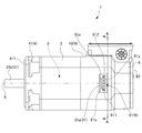
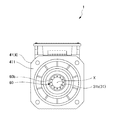
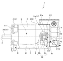
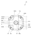
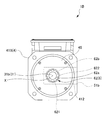
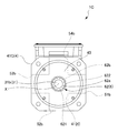
図1は、第1実施形態に係る電動機1の側面図である。図2は、第1実施形態に係る電動機1を軸方向前方から見た図である。図3は、第1実施形態に係る電動機1の軸方向後方から見た図である。図4は、図1の部分断面図であり、図5は、図2の部分断面図であり、図6は、図1のA−A線断面図であり、図7は、図6の第1蓋部材44を取り外した状態を示す図である。また、図8は、第1実施形態の変形例に係る電動機1Aの底面図である。図9は、図8のB−B線断面図であり、図10は、図9の第1蓋部材44Aを取り外した状態を示す図である。また、図11は、第1実施形態に係る電動機1を工作機械10の主軸11に結合したときの部分断面側面図である。
[First Embodiment]
FIG. 1 is a side view of the
ここで、軸方向とは、後述するロータ3の回転軸部31の軸線X方向を意味する。軸方向前方とは、工作機械10の主軸11に取り付けられる主軸取付面411側を意味し、例えば図1では左側を意味する。また、軸方向後方とは、ファンカバー8側を意味し、例えば図1では右側を意味する。
Here, the axial direction means the direction of the axis X of the
本実施形態に係る電動機1は、例えば誘導式電動機であり、後述するステータ2に図示しない巻線を有し、ロータ3に図示しない短絡された裸の導体を有し、巻線から導体への電磁誘導作用によって動作する。この誘導式電動機は、構造が簡単で保守も容易であることから、幅広く利用されている。
An
図1〜図7に示すように、本実施形態に係る電動機1は、ステータ2と、ロータ3と、ハウジング4と、を備える。
As shown in FIGS. 1 to 7, the
ステータ2は、筒状を有し、その内部(内側)に後述するロータ3が回転可能に配置される。ステータ2は、軸方向に積層された複数の磁性鋼板により構成される。ステータ2の周壁部21には、円周方向に等間隔で配置された図示しない複数のスロットが形成される。各スロットは、ステータ2の軸方向に延びて設けられ、図示しない巻線が収容されている。
The
ロータ3は、図示しないロータ本体と、回転軸部31と、を備える。
ロータ本体は、円柱状を有し、回転軸部31に対して同軸に設けられて該回転軸部31に固定されている。ロータ本体には、図示しない短絡された裸の導体が配置される。
回転軸部31は、ステータ2に対して回転可能に設けられ、ロータ本体と一体的に回転する。回転軸部31は、軸方向後方部分を構成する第1軸部31aと、軸方向前方部分を構成する第2軸部31bとにより構成される。第1軸部31aは、後述する後ハウジング42に回転可能に支持され、第2軸部31bは、工作機械10の主軸11に接続される(図11参照)。
The
The rotor body has a columnar shape, is provided coaxially with the
The
電動機1の軸方向後方部には、ロータ3の回転数を検出する回転検出部30が設けられている(図4参照)。この回転検出部30は、第1軸部31aに取り付けられた歯車状の検出用回転要素30aと、この検出用回転要素30aの回転数を検出する回転検出器30bと、により構成される。
A
ハウジング4は、ステータ2の軸方向両端に取り付けられ、ステータ2を支持する。ハウジング4は、ステータ2の軸方向前方に取り付けられる前ハウジング41と、ステータ2の軸方向後方に取り付けられる後ハウジング42と、を有する。
The
ハウジング4、つまり前ハウジング41及び後ハウジング42はいずれも、略四角筒状を有し、4つの主たる外周側面を有する。即ち、これらハウジングは、2つの側面(例えば図1において紙面に平行な面)と、上面(例えば図1において上側の面)と、底面(例えば図1において下側の面)と、を有する。また、これらハウジングは、四隅の角部が面取りされている。
The
前ハウジング41は、ステータ2の軸方向前方部に固定される。前ハウジング41の軸方向前方側の主軸取付面411には、後述する工作機械10の主軸頭12が接続される(図11参照)。
前ハウジング41の主軸取付面411側には、ラビリンス構造のラビリンス部材60が設けられている。このラビリンス部材60は、環境雰囲気中の油などが電動機1内に侵入するのを防止する。また、このラビリンス部材60は、円環状を有し、周方向に等間隔で形成され軸方向に延びる複数のバランス修正用のタップ60bを有する。図示しないがタップ60bに取り付ける芋ネジの重量、数及び配置を調整することで、電動機1のバランス修正が可能となっている。
The
A
後ハウジング42は、ステータ2の軸方向後方部に固定される。後ハウジング42の軸方向後方側の端面421には、後述する開口部51aの軸方向後方側を覆うように第1蓋部材44が取り付け固定されており(図6参照)、この第1蓋部材44を介して後述する冷却ファン7を収容するファンカバー8が取り付けられる。
後ハウジング42の外周側面のうち、一方側の側面(例えば図1において紙面手前側の側面)には、開口部51aが設けられている。また、この開口部51aから外部に露出する位置には、バランス修正用部品6としての第1バランス修正用部品61が配置されている。これら開口部51a及びバランス修正用部品6については、後段で詳述する。
The
Of the outer peripheral side surface of the
ところで、本実施形態の電動機1のような誘導式電動機では、動作の原理上、ステータ2やロータ3が発熱する。そこで、性能を維持するため電動機1は、冷却構造として、冷却ファン7と、ファンカバー8と、通気路9と、を備える。
By the way, in an induction motor such as the
冷却ファン7は、電動機1の軸方向後方側に配置され、後ハウジング42に取り付けられる(図4参照)。冷却ファン7は、例えば遠心型ファンであり、図示しないファンモータの駆動により回転することで、軸方向に気流を発生させる。
The cooling
ファンカバー8は、後ハウジング42に取り付けられ、内部に冷却ファン7を収容している。ファンカバー8には、その内部への外気の流入と内部からの気体の流出を可能とする複数のファン孔81が設けられている。より詳しくは、ファン孔81は、ファンカバー8の軸方向後端面82において、中心に位置する円状の中心部83と、該中心部83の外周から放射状に延びる複数の放射リブ84と、径の異なる複数の円環状の円環リブ85と、により区画されて形成される。
The
通気路9は、ステータ2の周壁部21において、軸方向に貫通する貫通孔により形成される(図4及び図5参照)。通気路9は、ステータ2の周壁部21において周方向に並んで複数形成されている。通気路9の軸方向前方側には流入口91が形成されており、軸方向後方側には流出口92が形成されている。
The
図4中に矢印で示すように、ファンモータの駆動により冷却ファン5が回転すると、軸方向に気流が発生して流入口91から外気が流入する。流入した外気は、通気路9内を軸方向後方に向かって流通して流出口92から流出し、ファンカバー8の内部を通ってファン孔81から排出される。これにより、電動機1の稼働により発熱するステータ2やステータ2を介してロータ3が冷却可能となっている。
As indicated by the arrows in FIG. 4, when the cooling fan 5 is rotated by driving the fan motor, an air flow is generated in the axial direction, and outside air flows from the
次に、開口部51a及びバランス修正用部品6について、詳しく説明する。
開口部51aは、後ハウジング42の外周側面のうち、一方側の側面に設けられている。側面視で、開口部51aの開口の大きさは、後述する第1バランス修正用部品61よりも大きく設定されている。即ち、第1バランス修正用部品61は、開口部51aから外部に露出しており、側面から視認及びアクセス可能となっている。
Next, the
The opening 51 a is provided on one side surface of the outer peripheral side surfaces of the
また、開口部51aは、後ハウジング42の軸方向後方側の端面421において、後述する第1バランス修正用部品61を囲むように設けられた仕切り壁422と、矩形状の第1蓋部材44と、により囲繞されて形成された凹部で構成される(図6及び図7参照)。仕切り壁422は軸方向後方に所定長さ延びて形成され、かかる凹部内に後述する第1バランス修正用部品61が収容されている。即ち、開口部51aは、ステータ2の内部空間Sと、ステータ2に形成された通気路9と、のいずれとも隔離されている。これにより、電動機1の防水性能や冷却性能への悪影響が回避されている。
In addition, the
バランス修正用部品6としての第1バランス修正用部品61は、回転軸部31の軸方向後方部分を構成する第1軸部31aに取り付けられる。第1バランス修正用部品61は、円盤状を有し、回転軸部31と同軸に配置されている。なお図1などでは、便宜上、第1バランス修正用部品61は部分的に断面で示している。
The first
第1バランス修正用部品61の軸方向後方側の端面61aには、周方向に等間隔で軸方向に延びる複数の第1タップ611が設けられ、取り付ける図示しない芋ネジの重量、数及び配置を調整することで、ロータ3のバランスが修正される。
A plurality of
また、第1バランス修正用部品61の外周側面61bには、周方向に等間隔で径方向に延びる複数の第2タップ612が設けられ、取り付ける図示しない芋ネジの重量、数及び配置を調整することで、ロータ3のバランスが修正される。
In addition, a plurality of
以上の構成を備える電動機1は、例えば次のようにしてバランス修正される。
まず、電動機1の組み立て前において、第1バランス修正用部品61の第1タップ611に取り付ける芋ネジの重量、数及び配置を調整し、ロータ3のバランスを修正する。
次いで、電動機1を組み立てた後に、開口部51aから第1バランス修正用部品61にアクセスして、第2タップ612に取り付ける芋ネジの重量、数及び配置を調整し、ロータ3のバランスを修正する。また、電動機1を長時間稼働させた後においても、同様の操作によりバランス修正される。
The
First, before assembling the
Next, after assembling the
以上の構成を備える電動機1は、図8〜図10に示すように、開口部の数や配置を変形できる。この変形例に係る電動機1Aは、後ハウジングの4つの外周側面のうち両側面と底面の3つの面に開口部が設けられている。即ち、電動機1Aの後ハウジング42Aの両側面には、開口部51a及び開口部53aが設けられており、底面には、開口部52aが設けられている。側面視で、いずれの開口部も、その開口の大きさが第1バランス修正用部品61よりも大きく設定されている。即ち、第1バランス修正用部品61は、いずれの開口部からも外部に露出しており、両側面及び底面から視認及びアクセス可能となっている。
As shown in FIGS. 8 to 10, the
これら開口部51a,52a,53aは、後ハウジング42Aの軸方向後方側の端面421Aにおいて、第1バランス修正用部品61を囲むように設けられた仕切り壁422Aと、略T字状の第1蓋部材44Aと、により囲繞されて形成された凹部で構成され、互いに連通している。仕切り壁422Aは軸方向後方に所定長さ延びて形成され、かかる凹部内に後述する第1バランス修正用部品61が収容されている。即ち、いずれの開口部も、ステータ2の内部空間Sと、ステータ2に形成された通気路9と、のいずれとも隔離されており、電動機1の防水性能や冷却性能への悪影響が回避されている。
The
本実施形態によれば、以下の効果が奏される。
本実施形態では、後ハウジング42の外周側面に、ステータ2の内部空間S及びステータ2に形成された通気路9とは隔離して配置される少なくとも1つの開口部51a(52a,53a)を設けた。また、ロータ3の回転軸部31に、ロータ3のバランスを修正する第1バランス修正用部品61を取り付け、該第1バランス修正用部品61を開口部51a(52a,53a)から外部に露出するように配置した。
これにより、電動機1(1A)の組立後や長期間稼働させた後においても、冷却ファン7やファンカバー8などを取り外すことなく、容易且つ高精度に電動機1(1A)のバランスを修正できる。また、開口部51a(52a,53a)は、ステータ2の内部空間Sや通気路9とは隔離されているため、電動機1(1A)の防水性能や冷却性能の低下を回避できる。
According to this embodiment, the following effects are produced.
In the present embodiment, at least one
Thereby, even after the motor 1 (1A) is assembled or operated for a long time, the balance of the motor 1 (1A) can be easily and accurately corrected without removing the cooling
[第2実施形態]
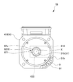
図12は、第2実施形態に係る電動機1Bの側面図である。図13は、第2実施形態に係る電動機1Bを軸方向前方から見た図である。図14は、図13の第2蓋部材45を取り外した状態を示す図である。図15は、図12の部分断面図であり、図16は、図13の部分断面図であり、図17は、図12のC−C線断面図である。また、図18は、第2実施形態の変形例に係る電動機1Cの側面図である。図19は、第2実施形態の変形例に係る電動機1Cの底面図である。図20は、第2実施形態の変形例に係る電動機1Cを軸方向前方から見た図である。図21は、図20の第2蓋部材45を取り外した状態を示す図である。図22は、第2実施形態に係る電動機1Bを工作機械10の主軸11に結合したときの部分断面側面図である。
[Second Embodiment]
FIG. 12 is a side view of the
本実施形態に係る電動機1Bは、開口部51aの代わりに開口部51bを備える点と、第1バランス修正用部品61の代わりに第2バランス修正用部品62を備える点が相違する以外は、第1実形態の電動機1と同一の構成である。以下、これらの相違点について詳しく説明する。
The
開口部51bは、前ハウジング41Bの外周側面のうち、一方側の側面に設けられている。側面視で、開口部51bの開口の大きさは、後述する第2バランス修正用部品62よりも大きく設定されている。即ち、第2バランス修正用部品62は、開口部51bから外部に露出しており、側面から視認及びアクセス可能となっている。
The
また、開口部51bは、前ハウジング41Bの軸方向前方側の端面、即ち主軸取付面411B側において、軸方向後方側に向かって凹んで形成されて後述する第2バランス修正用部品62を収容する凹部412と、該凹部412の軸方向前方側を覆うように設けられた円形状の第2蓋部材45と、により形成される(図13及び図14参照)。即ち、開口部51bは、ステータ2の内部空間Sと、ステータ2に形成された通気路9と、のいずれとも隔離されている。これにより、電動機1の防水性能や冷却性能への悪影響が回避されている。
In addition, the
バランス修正用部品6としての第2バランス修正用部品62は、回転軸部31の軸方向前方部分を構成する第2軸部31bに取り付けられる。第2バランス修正用部品62は、円盤状を有し、回転軸部31と同軸に配置されている。なお図12などでは、便宜上、第2バランス修正用部品62は部分的に断面で示している。
The second
第2バランス修正用部品62は、第1バランス修正用部品61と基本的には向きが逆である以外同様の構成である。即ち、第2バランス修正用部品62の軸方向前方側の端面62aには、周方向に等間隔で軸方向に延びる複数の第1タップ621が設けられ、取り付ける図示しない芋ネジの重量、数及び配置を調整することで、ロータ3のバランスが修正される。
The second
また、第2バランス修正用部品62の外周側面62bには、周方向に等間隔で径方向に延びる複数の第2タップ622が設けられ、取り付ける図示しない芋ネジの重量、数及び配置を調整することで、ロータ3のバランスが修正される。
In addition, a plurality of
以上の構成を備える電動機1Bは、例えば次のようにしてバランス修正される。
まず、電動機1Bの組み立て前において、第2バランス修正用部品62の第1タップ621に取り付ける芋ネジの重量、数及び配置を調整し、ロータ3のバランスを修正する。
次いで、電動機1Bを組み立てた後に、開口部51bから第2バランス修正用部品62にアクセスして、第2タップ622に取り付ける図示しない芋ネジの重量、数及び配置を調整し、ロータ3のバランスを修正する。また、電動機1Bを長時間稼働させた後においても、同様の操作によりバランス修正される。
The
First, before assembling the
Next, after assembling the
以上の構成を備える電動機1Bは、図18〜図22に示すように、開口部の数や配置を変形できる。この変形例に係る電動機1Cは、前ハウジングの4つの外周側面の全ての面に開口部が設けられている。即ち、電動機1Cの前ハウジング41Cの両側面には開口部51b及び開口部53bが設けられており、底面には開口部52bが設けられており、上面には開口部54bが設けられている。側面視で、いずれの開口部も、その開口の大きさが第2バランス修正用部品62よりも大きく設定されている。即ち、第2バランス修正用部品62は、いずれの開口部からも外部に露出しており、両側面、底面及び上面から視認及びアクセス可能となっている。
As shown in FIGS. 18 to 22, the
これら開口部51b,52b,53b,54bは、前ハウジング41Cの軸方向前方側の端面、即ち主軸取付面411C側において、十字状に軸方向後方側に向かって凹んで形成されて後述する第2バランス修正用部品62を中央に収容する凹部412Cと、該凹部412Cの軸方向前方側を覆うように設けられた円形状の第2蓋部材45と、により構成され、互いに連通している。即ち、いずれの開口部も、ステータ2の内部空間Sと、ステータ2に形成された通気路9と、のいずれとも隔離されており、電動機1の防水性能や冷却性能への悪影響が回避されている。
These
本実施形態によれば、第1実施形態と同様の効果が奏される。特に本実施形態によれば、電動機1B(1C)を工作機械10の主軸11に結合した後であっても、容易且つ高精度にバランス修正が可能である。また、開口部51b(52b,53b,54b)は、ステータ2の内部空間Sや通気路9とは隔離されているため、電動機1B(1C)の防水性能や冷却性能の低下を回避できる。
According to the present embodiment, the same effects as those of the first embodiment are exhibited. In particular, according to the present embodiment, even after the
[第3実施形態]
図23は、第3実施形態に係る電動機1Dの側面図である。本実施形態に係る電動機1Dは、第1実施形態と第2実施形態とを組み合わせたものである。即ち、開口部が、後ハウジング及び前ハウジングのいずれにも設けられている点と、第1バランス修正用部品61及び第2バランス修正用部品62のいずれもが設けられている点が相違する以外は、第1実施形態及び第2実施形態と同一の構成である。
なお、本実施形態の変形例としては、第1実施形態の変形例や第2実施形態の変形も含めた組み合わせを採用することができる。
このような構成を備える本実施形態によれば、第1実施形態及び第2実施形態と同様の効果が奏される。
[Third Embodiment]
FIG. 23 is a side view of the
In addition, as a modification of this embodiment, the combination including the modification of 1st Embodiment and the modification of 2nd Embodiment is employable.
According to this embodiment having such a configuration, the same effects as those of the first embodiment and the second embodiment are exhibited.
なお、本発明は上記実施形態に限定されるものではなく、本発明の目的を達成できる範囲での変形、改良は本発明に含まれる。
上述の各実施形態では、ハウジングの形状を略四角筒状としたが、これに限定されない。円筒状でもよく、四角以外の角筒状でもよい。また、開口部は、前ハウジング及び後ハウジングいずれにおいても、外周側面に少なくとも1つ設けられていればよい。
また、開口部はバランス修正部品よりも大きくなくてもよく、バランス修正部品の側面に設けられた少なくとも1個のタップが視認、アクセス可能であればよい。
It should be noted that the present invention is not limited to the above-described embodiment, and modifications and improvements within the scope that can achieve the object of the present invention are included in the present invention.
In each of the above-described embodiments, the shape of the housing is a substantially rectangular tube shape, but is not limited thereto. A cylindrical shape may be sufficient and square tube shapes other than a square may be sufficient. Further, at least one opening may be provided on the outer peripheral side surface in both the front housing and the rear housing.
Further, the opening may not be larger than the balance correction component, and it is sufficient that at least one tap provided on the side surface of the balance correction component is visible and accessible.
1,1A,1B,1C,1D 電動機
2 ステータ(固定子)
3 ロータ(回転子)
4 ハウジング
9 通気路
10 工作機械
31 回転軸部
41 前ハウジング(ハウジング)
42 後ハウジング(ハウジング)
51a,52a,53a,51b,52b,53b,54b 開口部
6 バランス修正用部品
61 第1バランス修正用部品(バランス修正用部品)
62 第2バランス修正用部品(バランス修正用部品)
611,621 第1タップ(バランス修正部)
612,622 第2タップ(バランス修正部)
1, 1A, 1B, 1C,
3 Rotor (rotor)
4
42 Rear housing (housing)
51a, 52a, 53a, 51b, 52b, 53b,
62 Second balance correction component (balance correction component)
611, 621 First tap (balance correction unit)
612, 622 2nd tap (balance corrector)
Claims (5)
前記ハウジングの外周側面に少なくとも1つ設けられ、前記固定子の内部空間及び前記固定子に形成された通気路とは隔離して配置される開口部と、
前記回転軸部に取り付けられ、前記回転子のバランスを修正するバランス修正用部品と、を備え、
前記バランス修正用部品は、前記開口部から外部に露出している電動機。 An electric motor comprising: a cylindrical stator; a rotor having a rotary shaft portion inserted into the stator; and housings attached to both axial ends of the stator,
At least one opening provided on the outer peripheral side surface of the housing, and an opening disposed separately from the internal space of the stator and the air passage formed in the stator;
A balance correcting component that is attached to the rotating shaft and corrects the balance of the rotor;
The balance correcting component is an electric motor exposed to the outside through the opening.
前記開口部は、前記4つの外周側面のうち少なくとも1つに設けられている請求項1に記載の電動機。 The housing has a rectangular tube shape having at least four outer peripheral sides,
The electric motor according to claim 1, wherein the opening is provided in at least one of the four outer peripheral side surfaces.
Priority Applications (5)
| Application Number | Priority Date | Filing Date | Title |
|---|---|---|---|
| JP2016104665A JP6450711B2 (en) | 2016-05-25 | 2016-05-25 | Electric motor having balance structure and machine tool including the electric motor |
| US15/600,821 US10333375B2 (en) | 2016-05-25 | 2017-05-22 | Electric motor having balance structure and machine tool equipped with the electric motor |
| CN201720581121.9U CN206850638U (en) | 2016-05-25 | 2017-05-23 | Motor and the lathe for possessing the motor |
| DE102017208677.7A DE102017208677B4 (en) | 2016-05-25 | 2017-05-23 | Electric motor with balancing structure and machine tool equipped with the electric motor |
| CN201710367556.8A CN107437877B (en) | 2016-05-25 | 2017-05-23 | Motor with balancing structure and the lathe for having the motor |
Applications Claiming Priority (1)
| Application Number | Priority Date | Filing Date | Title |
|---|---|---|---|
| JP2016104665A JP6450711B2 (en) | 2016-05-25 | 2016-05-25 | Electric motor having balance structure and machine tool including the electric motor |
Publications (2)
| Publication Number | Publication Date |
|---|---|
| JP2017212811A true JP2017212811A (en) | 2017-11-30 |
| JP6450711B2 JP6450711B2 (en) | 2019-01-09 |
Family
ID=60269123
Family Applications (1)
| Application Number | Title | Priority Date | Filing Date |
|---|---|---|---|
| JP2016104665A Expired - Fee Related JP6450711B2 (en) | 2016-05-25 | 2016-05-25 | Electric motor having balance structure and machine tool including the electric motor |
Country Status (4)
| Country | Link |
|---|---|
| US (1) | US10333375B2 (en) |
| JP (1) | JP6450711B2 (en) |
| CN (2) | CN107437877B (en) |
| DE (1) | DE102017208677B4 (en) |
Families Citing this family (1)
| Publication number | Priority date | Publication date | Assignee | Title |
|---|---|---|---|---|
| CN110905731B (en) * | 2019-11-14 | 2021-05-11 | 许昌许继风电科技有限公司 | Wind turbine dynamic balance method |
Citations (5)
| Publication number | Priority date | Publication date | Assignee | Title |
|---|---|---|---|---|
| JPS6069301U (en) * | 1983-10-18 | 1985-05-16 | 株式会社東芝 | balance weight attachment device |
| JPH0260456A (en) * | 1988-08-26 | 1990-02-28 | Hitachi Ltd | Superconducting rotating electric machine |
| JP2004204748A (en) * | 2002-12-25 | 2004-07-22 | Toyota Industries Corp | Compressor and method for balancing compressor |
| JP2013158114A (en) * | 2012-01-27 | 2013-08-15 | Toyota Motor Corp | Device and method for adjusting rotor axis of dynamo-electric machine |
| JP2016082629A (en) * | 2014-10-10 | 2016-05-16 | ファナック株式会社 | Electric motor capable of cleaning stator air passage or fan, and electric motor cleaning system |
Family Cites Families (10)
| Publication number | Priority date | Publication date | Assignee | Title |
|---|---|---|---|---|
| US2558737A (en) * | 1946-12-13 | 1951-07-03 | Master Electric Co | Rotor balancing means |
| JPS568894U (en) | 1979-07-02 | 1981-01-26 | ||
| JP2716237B2 (en) | 1990-02-27 | 1998-02-18 | ファナック株式会社 | Motor balance structure |
| US5487640A (en) * | 1994-03-16 | 1996-01-30 | Dresser-Rand Company | Balancing rings for assembled steam turbines |
| JP2966799B2 (en) * | 1996-11-07 | 1999-10-25 | ファナック株式会社 | Air-cooled motor |
| JP2008043149A (en) * | 2006-08-09 | 2008-02-21 | Toyota Industries Corp | Motor cooling structure |
| JP4787351B2 (en) * | 2009-11-09 | 2011-10-05 | ファナック株式会社 | Induction motor with a heat dissipation disk that dissipates heat generated in the rotor |
| CN203398888U (en) * | 2013-07-31 | 2014-01-15 | 无锡法拉第电机有限公司 | High-voltage generator rotor of novel dynamic balancing structure |
| JP5845295B2 (en) * | 2014-01-31 | 2016-01-20 | ファナック株式会社 | Motor cooling device |
| JP6450714B2 (en) * | 2016-06-24 | 2019-01-09 | ファナック株式会社 | Electric motor with terminal box having balance structure and machine tool provided with the electric motor |
-
2016
- 2016-05-25 JP JP2016104665A patent/JP6450711B2/en not_active Expired - Fee Related
-
2017
- 2017-05-22 US US15/600,821 patent/US10333375B2/en active Active
- 2017-05-23 DE DE102017208677.7A patent/DE102017208677B4/en not_active Expired - Fee Related
- 2017-05-23 CN CN201710367556.8A patent/CN107437877B/en not_active Expired - Fee Related
- 2017-05-23 CN CN201720581121.9U patent/CN206850638U/en not_active Expired - Fee Related
Patent Citations (5)
| Publication number | Priority date | Publication date | Assignee | Title |
|---|---|---|---|---|
| JPS6069301U (en) * | 1983-10-18 | 1985-05-16 | 株式会社東芝 | balance weight attachment device |
| JPH0260456A (en) * | 1988-08-26 | 1990-02-28 | Hitachi Ltd | Superconducting rotating electric machine |
| JP2004204748A (en) * | 2002-12-25 | 2004-07-22 | Toyota Industries Corp | Compressor and method for balancing compressor |
| JP2013158114A (en) * | 2012-01-27 | 2013-08-15 | Toyota Motor Corp | Device and method for adjusting rotor axis of dynamo-electric machine |
| JP2016082629A (en) * | 2014-10-10 | 2016-05-16 | ファナック株式会社 | Electric motor capable of cleaning stator air passage or fan, and electric motor cleaning system |
Also Published As
| Publication number | Publication date |
|---|---|
| DE102017208677A1 (en) | 2017-11-30 |
| CN107437877A (en) | 2017-12-05 |
| DE102017208677B4 (en) | 2024-05-16 |
| US20170346362A1 (en) | 2017-11-30 |
| US10333375B2 (en) | 2019-06-25 |
| CN206850638U (en) | 2018-01-05 |
| CN107437877B (en) | 2019-11-05 |
| JP6450711B2 (en) | 2019-01-09 |
Similar Documents
| Publication | Publication Date | Title |
|---|---|---|
| JP6702318B2 (en) | Blower and vacuum cleaner | |
| US9077230B2 (en) | Electric motor with heat dissipating device | |
| CN105099080B (en) | Ceiling fan motor | |
| WO2017082222A1 (en) | Blowing device and cleaner | |
| US10184492B2 (en) | Axial flow fan | |
| US20130216410A1 (en) | Blower assembly with motor integrated into the impeller fan and blower housing constructions | |
| JP7465624B2 (en) | Actuator | |
| JP4407158B2 (en) | Portable power tools | |
| US20110109176A1 (en) | Induction motor equipped with heat dissipating disc for dissipating rotor heat | |
| JP6450714B2 (en) | Electric motor with terminal box having balance structure and machine tool provided with the electric motor | |
| JP6007951B2 (en) | Rotating electric machine | |
| JP6450711B2 (en) | Electric motor having balance structure and machine tool including the electric motor | |
| CN113966440A (en) | Rotating device | |
| JP6172877B2 (en) | Rotating electrical machine unit | |
| JP6720923B2 (en) | Blower | |
| JP7524768B2 (en) | Ducted Fan | |
| JP5468237B2 (en) | Electric motor | |
| JP6857871B2 (en) | Electric tool | |
| JP2021090254A (en) | Electric motor | |
| JP2023039145A (en) | Axial flow fan | |
| JP2014212586A (en) | Rotary electric machine | |
| JP5621553B2 (en) | Rotating electric machine | |
| JP2021078319A (en) | Motor rotor and motor | |
| CN119341287A (en) | Rotating electric machines | |
| CN121308439A (en) | Rotary motor |
Legal Events
| Date | Code | Title | Description |
|---|---|---|---|
| A977 | Report on retrieval |
Free format text: JAPANESE INTERMEDIATE CODE: A971007 Effective date: 20180427 |
|
| A131 | Notification of reasons for refusal |
Free format text: JAPANESE INTERMEDIATE CODE: A131 Effective date: 20180508 |
|
| A521 | Request for written amendment filed |
Free format text: JAPANESE INTERMEDIATE CODE: A523 Effective date: 20180619 |
|
| TRDD | Decision of grant or rejection written | ||
| A01 | Written decision to grant a patent or to grant a registration (utility model) |
Free format text: JAPANESE INTERMEDIATE CODE: A01 Effective date: 20181113 |
|
| A61 | First payment of annual fees (during grant procedure) |
Free format text: JAPANESE INTERMEDIATE CODE: A61 Effective date: 20181210 |
|
| R150 | Certificate of patent or registration of utility model |
Ref document number: 6450711 Country of ref document: JP Free format text: JAPANESE INTERMEDIATE CODE: R150 |
|
| LAPS | Cancellation because of no payment of annual fees |