JP2017210206A - Vehicle body structure - Google Patents
Vehicle body structure Download PDFInfo
- Publication number
- JP2017210206A JP2017210206A JP2016106406A JP2016106406A JP2017210206A JP 2017210206 A JP2017210206 A JP 2017210206A JP 2016106406 A JP2016106406 A JP 2016106406A JP 2016106406 A JP2016106406 A JP 2016106406A JP 2017210206 A JP2017210206 A JP 2017210206A
- Authority
- JP
- Japan
- Prior art keywords
- panel
- cross member
- floor
- floor cross
- vehicle body
- Prior art date
- Legal status (The legal status is an assumption and is not a legal conclusion. Google has not performed a legal analysis and makes no representation as to the accuracy of the status listed.)
- Granted
Links
Images


Landscapes
- Body Structure For Vehicles (AREA)
Abstract
【課題】サイドシルの側面に衝撃荷重が入力された場合と、サイドシルよりも上方側部分に衝撃荷重が入力された場合のいずれにおいても、望ましい乗室保護性能を発揮することができる車体構造を提供する。
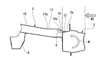
【解決手段】車両は、フロアパネルの車幅方向両側に配置された一対のサイドシル2と、両端部が一対のサイドシル2に結合されたフロアクロスメンバ5と、を備えている。フロアクロスメンバ5は、一対のサイドシル2の各上壁に接合される端縁接合部12と、車幅方向内側から外側に向かって下方傾斜して接合部に連設される高剛性部と、高剛性部の車幅方向内側に連設される中央上壁16と、を有している。端縁接合部12と高剛性部と中央上壁16はサイドシル2の上壁2aの上面よりも上方に配置されている。中央上壁16には、凹状に下方に窪む下方屈曲部17が設けられている。
【選択図】図6The present invention provides a vehicle body structure capable of exhibiting desirable passenger compartment protection performance both when an impact load is input to a side surface of a side sill and when an impact load is input to a portion above the side sill. To do.
The vehicle includes a pair of side sills 2 disposed on both sides of the floor panel in the vehicle width direction, and a floor cross member 5 having both ends coupled to the pair of side sills 2. The floor cross member 5 includes an edge joint portion 12 joined to each upper wall of the pair of side sills 2, a high-rigidity portion that slopes downward from the vehicle width direction inner side toward the outer side, and is provided continuously to the joint portion. And a central upper wall 16 connected to the inside of the high rigidity portion in the vehicle width direction. The edge joint portion 12, the high-rigidity portion, and the central upper wall 16 are disposed above the upper surface of the upper wall 2 a of the side sill 2. The central upper wall 16 is provided with a downward bent portion 17 that is recessed downward in a concave shape.
[Selection] Figure 6
Description
本発明は、車両の下部の車体構造に関するものである。 The present invention relates to a vehicle body structure under a vehicle.
車両の下部の車体構造として、フロアパネルの左右の両側に、車体前後方向に略沿って延出するサイドシルが配置され、車幅方向に略沿って延出するフロアクロスメンバが左右のサイドシルに結合されたものがある(例えば、特許文献1,2参照)。
As the body structure of the lower part of the vehicle, side sills extending approximately along the longitudinal direction of the vehicle body are arranged on both the left and right sides of the floor panel, and floor cross members extending substantially along the vehicle width direction are coupled to the left and right side sills. (For example, refer to
特許文献1に記載の車体構造は、左右のサイドシルの内側側面に、フロアパネルとフロアクロスメンバの左右の各端部が結合され、フロアクロスメンバの上面に脆弱部であるビードが形成されている。この車体構造においては、サイドシルの外側側面に衝撃荷重が入力されたときに、フロアクロスメンバがビード部分を屈曲基点として曲がることで入力衝撃を効率良く吸収する。
In the vehicle body structure described in
特許文献2に記載の車体構造は、左右のサイドシルの内側側面に、フロアパネルとフロアクロスメンバの左右の各端部が結合され、さらに、左右のサイドシルの上面とフロアクロスメンバの側縁部の上面とに補強部材が跨って接合されている。補強部材は、サイドシルの上面からフロアクロスメンバの上面に向かって斜め下方に傾斜し、その斜め下方に傾斜した部分に補強ビードが設けられている。この車体構造の場合、サイドシルの外側側面に衝撃荷重が入力されると、衝撃荷重がフロアクロスメンバの側端部と補強部材を通してフロアクロスメンバの中央領域に伝達され、このときフロアクロスメンバが補強ビードの終端部付近を屈曲基点として曲がることで入力衝撃を効率良く吸収する。
In the vehicle body structure described in
しかしながら、特許文献1,2に記載の車体構造は、いずれもフロアクメスメンバの上面が左右のサイドシルの上面よりも低く、サイドシルの側面に襲撃荷重が入力されたときに屈曲基点となる部分もサイドシルの上面よりも低い位置となっている。
このため、サイドシルの側面に衝撃荷重が入力された場合には、フロアクロスメンバ上の脆弱部を基点として望ましい衝撃吸収性能を発揮することができるが、サイドシルよりも上方側部分、例えば、センターピラー部分等に衝撃荷重が入力された場合には、サイドシルの上部を車幅方向内側に倒す回転モーメントに対してフロアクロスメンバは大きな抗力を発揮しにくい。
However, in the vehicle body structures described in
For this reason, when an impact load is input to the side of the side sill, the desired shock absorbing performance can be exhibited with the fragile part on the floor cross member as a base point, but the upper part of the side sill, for example, the center pillar When an impact load is input to a portion or the like, the floor cross member is unlikely to exert a great resistance against a rotational moment that tilts the upper part of the side sill inward in the vehicle width direction.
そこで本発明は、サイドシルの側面に衝撃荷重が入力された場合と、サイドシルよりも上方側部分に衝撃荷重が入力された場合のいずれにおいても、望ましい乗室保護性能を発揮することができる車体構造を提供しようとするものである。 Therefore, the present invention provides a vehicle body structure capable of exhibiting desirable passenger compartment protection performance both when an impact load is input to the side surface of the side sill and when an impact load is input to a portion above the side sill. Is to provide.
本発明に係る車体構造は、上記課題を解決するために、以下の構成を採用した。
即ち、本発明に係る車体構造は、フロアパネル(例えば、実施形態のフロアパネル3)の車幅方向両側に車体前後方向に略沿って配置された一対のサイドシル(例えば、実施形態のサイドシル2)と、車幅方向に略沿って延出して、両端部が一対の前記サイドシルに結合されたフロアクロスメンバ(例えば、実施形態のフロアクロスメンバ5)と、を備え、前記フロアクロスメンバは、一対の前記サイドシルの各上壁に接合される端縁接合部(例えば、実施形態の端縁接合部12)と、車幅方向内側から外側に向かって下方傾斜して前記端縁接合部に連設される高剛性部(例えば、実施形態のビード14)と、前記高剛性部の車幅方向内側に連設される中央上壁(例えば、実施形態の中央上壁16)と、を有し、前記端縁接合部と前記高剛性部と前記中央上壁が前記サイドシルの前記上壁の上面よりも上方に配置され、前記中央上壁に、凹状に下方に窪む下方屈曲部(例えば、実施形態の下方屈曲部17)が設けられていることを特徴とする。
The vehicle body structure according to the present invention employs the following configuration in order to solve the above problems.
That is, the vehicle body structure according to the present invention includes a pair of side sills (for example, the
上記の構成により、サイドシルの側面に衝撃荷重が入力された場合には、サイドシルに入力された衝撃荷重がフロアクロスメンバの端縁接合部を通して高剛性部と下方屈曲部に作用し、このとき高剛性部の頂部と下方屈曲部の底部を屈曲基点としてフロアクロスメンバが蛇腹状に屈曲する。フロアクロスメンバはこの間に入力衝撃を吸収する。
また、車両のサイドシルよりも上方側部分に衝撃荷重が入力され、サイドシルの上部を車幅方向内側に倒す回転モーメントがサイドシルに作用すると、サイドシルの上壁に端縁接合部を介して接続されたフロアクロスメンバの高剛性部が上記回転モーメントに対して反力を作用させる。このとき、フロアクロスメンバは、下方屈曲部を含む中央上壁と高剛性部がサイドシルの上壁の上面よりも上方側に位置されているため、下方屈曲部には屈曲が生じにくくなる。したがって、車両のサイドシルよりも上方側部分に衝撃荷重が入力された場合には、サイドシルの上部の車幅方向内側への倒れを抑制し、センターピラー等の側壁部材の変形を抑制することができる。
With the above configuration, when an impact load is input to the side surface of the side sill, the impact load input to the side sill acts on the high rigidity portion and the downward bending portion through the edge joint portion of the floor cross member. The floor cross member bends in a bellows shape with the top of the rigid portion and the bottom of the downward bent portion as the bending base point. The floor cross member absorbs the input impact during this time.
In addition, when an impact load is input to the upper part of the side sill of the vehicle and a rotational moment that tilts the upper part of the side sill inward in the vehicle width acts on the side sill, the side sill is connected to the upper wall of the side sill via an edge joint. The highly rigid portion of the floor cross member applies a reaction force to the rotational moment. At this time, in the floor cross member, the central upper wall including the lower bent portion and the high-rigidity portion are positioned above the upper surface of the upper wall of the side sill, so that the lower bent portion is less likely to be bent. Therefore, when an impact load is input to a portion above the side sill of the vehicle, it is possible to suppress the upper side of the side sill from falling inward in the vehicle width direction and to suppress deformation of the side wall member such as the center pillar. .
前記フロアクロスメンバは、前記端縁接合部から車幅方向内側に直線状に延出する内側延長部(例えば、実施形態の内側延長部13)を有し、前記高剛性部は、前記内側延長部に対して上方に隆起するビード(例えば、実施形態のビード14)によって構成されるようにしても良い。
この場合、内側延長部から上方に隆起するビードが、サイドシルの回転モーメントに対して大きな抗力を生じるようになる。また、内側延長部が端縁接合部から直線状に延出しているため、端縁延長部をサイドシルの上壁の上面に対して安定して当接させ易くなる。
The floor cross member has an inner extension (for example, the
In this case, the bead that protrudes upward from the inner extension portion generates a large resistance against the rotational moment of the side sill. In addition, since the inner extension portion extends linearly from the edge joint portion, the end edge extension portion can easily be stably brought into contact with the upper surface of the upper wall of the side sill.
前記フロアクロスメンバの前記下方屈曲部を跨ぐ位置には、乗員着座用のシートを取り付けるための取付ブラケット(例えば、実施形態の取付ブラケット18)が固定されるようにしても良い。
この場合、シート取付用の取付ブラケットがフロアクロスメンバの下方屈曲部を補強することになる。このため、サイドシルよりも上方側部分に衝撃荷重が入力されたときに、サイドシルの回転モーメントに対する反力を発生し易くなる。
A mounting bracket (for example, the
In this case, the mounting bracket for mounting the seat reinforces the downward bent portion of the floor cross member. For this reason, when an impact load is input to the upper part of the side sill, a reaction force against the rotational moment of the side sill is easily generated.
前記フロアパネルは、前記フロアクロスメンバの前方側に配置される低位パネル(例えば、実施形態の低位パネル3A)と、前記フロアクロスメンバの後方側に配置され、少なくとも前縁部が前記低位パネルよりも高位となる高位パネル(例えば、実施形態の高位パネル3B)と、を有し、前記フロアクロスメンバは、閉断面を構成する上板部材(例えば、実施形態の上板部材5U)と下板部材(例えば、実施形態の下板部材5L)とを有し、前記上板部材と前記下板部材が前後のフランジ部(例えば、実施形態のフランジ部5U−f,5L−f、及び、5U−r,5L−r)で相互に接合されているとともに、前後の前記フランジ部が前記低位パネルと前記高位パネルにそれぞれ接合されている構成としても良い。
この場合、フロアパネルは、低位パネルと高位パネルに分離して構成されているが、低位パネルと高位パネルは、これらの間においてフロアクロスメンバの前後のフランジ部にそれぞれ接合されることで、両者の間の剛性が高く維持される。さらに、フロアクロスメンバは、閉断面を構成する上板部材と下板部材とを有しているため、上板部材と下板部材を相互に接合する前に、上板部材に高剛性部や下方屈曲部を形成することができる。したがって、この構成を採用することにより、フロアメンバの加工を容易にすることができる。
The floor panel is disposed on the front side of the floor cross member (for example, the
In this case, the floor panel is composed of a low panel and a high panel, but the low panel and the high panel are joined to the front and rear flanges of the floor cross member between them, The rigidity during is kept high. Further, since the floor cross member has an upper plate member and a lower plate member that constitute a closed cross section, before joining the upper plate member and the lower plate member to each other, A downward bent portion can be formed. Therefore, by adopting this configuration, processing of the floor member can be facilitated.
前記上板部材と前記下板部材は、互いに接合されるフランジ部の間に前記高位パネルと前記低位パネルの一方が挟み込まれた状態で接合されるようにしても良い。
この場合、フロアクロスメンバと高位パネルや低位パネルとの接合部剛性をより高めることができる。
The upper plate member and the lower plate member may be joined in a state in which one of the high level panel and the low level panel is sandwiched between flange portions to be joined to each other.
In this case, the joint rigidity between the floor cross member and the high and low panels can be further increased.
前記フロアパネルの下面側には、車体前後方向に略沿って延出するフロアフレーム(例えば、実施形態のフロアフレーム9)が配置され、前記フロアフレームのうちの前記低位パネルと前記高位パネルの境界部位置には、前記フロアクロスメンバの下方を前後に跨ぎ当該フロアクロスメンバの下面に固定される凹状固定部(例えば、実施形態の凹状固定部11)が設けられるようにしても良い。
この場合、車体前後方向に略沿って配置されるフロアフレームの上方側に、左右のサイドシルを連結するフロアクロスメンバが車幅方向に略沿って配置され、フロアフレームの凹状固定部にフロアクロスメンバの下面が固定されることになる。したがって、車幅方向中央領域の剛性が高まり、サイドシルからフロアクロスメンバに入力される荷重を高い剛性で支持することが可能になる。
On the lower surface side of the floor panel, a floor frame (for example, the
In this case, a floor cross member that connects the left and right side sills is disposed substantially along the vehicle width direction on the upper side of the floor frame that is disposed substantially along the vehicle body longitudinal direction, and the floor cross member is disposed on the concave fixing portion of the floor frame. The lower surface of is fixed. Accordingly, the rigidity in the center region in the vehicle width direction is increased, and the load input from the side sill to the floor cross member can be supported with high rigidity.
前記フロアフレームの前記高位パネルの下方に配置される部位の左右の側壁は、前記低位パネルの下方に配置される部位の左右の側壁よりも上方突出高さが高く設定され、前記高位パネルの下方に配置される部位の左右の前記側壁の少なくとも一方は補強ビード(例えば、実施形態の補強ビード10)を有する構成であっても良い。
この場合、フロアフレームの側壁の高さの高い部位においては、補強ビードによって側壁の支持剛性を確保することができる。したがって、高位パネルに対する支持剛性を有利に高めることができる。
The left and right side walls of the portion of the floor frame disposed below the high level panel are set to have a higher upward projection height than the left and right side walls of the portion disposed below the low level panel, and below the high level panel. The structure which has a reinforcement bead (for example, the reinforcement bead 10 of embodiment) may be sufficient as at least one of the said left and right side walls of the site | part arrange | positioned.
In this case, the support rigidity of the side wall can be ensured by the reinforcing bead in the portion where the height of the side wall of the floor frame is high. Therefore, it is possible to advantageously increase the support rigidity for the high-level panel.
本発明によれば、フロアクロスメンバが端縁接合部と高剛性部と中央上壁とを有し、端縁接合部と高剛性部と中央上壁がサイドシルの上壁の上面よりも上方に配置され、中央上壁に下方屈曲部が設けられているため、サイドシルの側面に衝撃荷重が入力された場合には、高剛性部の頂部と下方屈曲部の底部を屈曲基点としてフロアクロスメンバを効率良く屈曲させることができ、サイドシルよりも上方側部分に衝撃荷重が入力された場合には、フロアクロスメンバの高剛性部が、サイドシルに作用する回転モーメントに対して反力を作用させることができる。 According to the present invention, the floor cross member has the edge joint portion, the high rigidity portion, and the central upper wall, and the edge joint portion, the high rigidity portion, and the central upper wall are located above the upper surface of the upper wall of the side sill. Since the lower bent part is provided on the central upper wall, when an impact load is input to the side of the side sill, the floor cross member is placed with the top part of the high rigidity part and the bottom part of the lower bent part as the bending base points. It can be bent efficiently, and when an impact load is input to the upper part of the side sill, the highly rigid part of the floor cross member can apply a reaction force to the rotational moment acting on the side sill. it can.
以下、本発明の一実施形態を図面に基づいて説明する。なお、以下の説明における前後左右等の向きは、特に記載が無ければ車両における向きと同一とする。また、以下の説明に用いる図中適所には、車両前方を示す矢印FR、車両左方を示す矢印LH、車両上方を示す矢印UPが記されている。 Hereinafter, an embodiment of the present invention will be described with reference to the drawings. Note that the directions such as front, rear, left and right in the following description are the same as those in the vehicle unless otherwise specified. Further, in the drawings used for the following description, an arrow FR indicating the front of the vehicle, an arrow LH indicating the left side of the vehicle, and an arrow UP indicating the upper side of the vehicle are described.
図1は、本実施実施形態の車両1の骨格部を右前部斜め上方側から見た図である。
車両1の左右の側部の下端には、車体前後方向に略沿って延出するサイドシル2が配置されている。左右のサイドシル2の車幅方向内側面には、乗員室の下方のフロアパネル3の左右両端部が接合されている。左右のサイドシル2の車体前後方向の略中央部にはセンターピラー4が立設されている。左右のサイドシル2のセンターピラー4の立設位置よりも前方側には、車幅方向に略沿って延出して左右のサイドシル2を連結するフロアクロスメンバ5が配置されている。また、フロアパネル3の車幅方向の略中央には、下側に開口する略コ字状の断面が車体前後に連続するフロアトンネル6が設けられている。
FIG. 1 is a view of a skeleton portion of a
A
図2は、車両1を図1のII−II断面線に沿って一部を断面にして、左後部斜め下方から見た図であり、図3は、図1のIII部を拡大した図である。また、図4は、図2のIV部を拡大して示した図であり、図5は、図2のIV−IV線に沿う断面を示した図である。
FIG. 2 is a view of the
フロアパネル3は、フロアクロスメンバ5の前方側に配置される低位パネル3Aと、フロアクロスメンバ5の後方側に配置され、少なくとも前縁部3B−1が低位パネル3Aよりも所定高さ高位となる高位パネル3Bと、を備えている。
The
低位パネル3Aは、後端部に立ち上がり壁3A−1を有し、その立ち上がり壁3A−1よりも前方側の略平坦な領域がシートに着座した乗員が足を載せ置く足載せ部3A−2とされている。
The
高位パネル3Bの前縁部3B−1は、低位パネル3Aの立ち上がり壁3A−1の上端部や高位パネル3Bの後部領域よりも上方に膨出している。この上方に膨出した前縁部3B−1の下方には、燃料タンク7(図5参照)やマフラー8が配置されている。なお、図2においては、燃料タンク7の図示は省略されている。
The
フロアクロスメンバ5は、図4に示すように、長尺な金属製の上板部材5Uと下板部材5Lが前後のフランジ部5U−f,5L−f、及び、5U−r,5L−rで相互に接合されて略矩形状の閉断面に形成されている。上板部材5Uと下板部材5Lの前部側のフランジ部5U−f,5L−fは、フロアクロスメンバ5の閉断面の前壁から下方に向かって延出しており、後部側のフランジ部5U−r,5L−rは、フロアクロスメンバ5の閉断面の後壁から車体後方側に向かって延出している。
As shown in FIG. 4, the
前部側のフランジ部5U−f,5L−fの前面側には、低位パネル3Aの立ち上がり壁3A−1が重ねられ、その立ち上がり壁3A−1がフランジ部5U−f,5L−fに対して溶接固定されている。
また、後部側のフランジ部5U−r,5L−rの間には、上位パネル3Bの前縁部3B−1が配置されている。上位パネル3Bの前縁部3B−1は、その状態でフランジ部5U−r,5L−rに溶接固定されている。
On the front side of the
A
また、フロアパネル3の下面のうちの、左右のサイドシル2と中央のフロアトンネル6の間には、車体前後方向に略沿って延出するフロアフレーム9が配置されている。フロアフレーム9は、左右のサイドシル2よりも車幅方向内側位置においてフロアパネル3の下面を支持するフレーム部材であり、前端部と後端部は図示しない他の車体フレーム部材に結合されている。フロアフレーム9は、図5に示すように、上方が開口するハット状の断面形状に形成され、底壁9bと左右の側壁9sとを有している。
Also, a
図2に示すように、フロアフレーム9のうちの、高位パネル3Bの下方に配置される部位の左右の側壁9s−1は、低位パネル3Aの下方に配置される部位の左右の側壁9s−2よりも上方突出高さが高く設定されている。即ち、高位パネル3Bの下方に配置される部位の左右の側壁9s−1は、低位パネル3Aと高位パネル3Bの間の段差部を挟んで上方突出高さが高くなっている。
高位パネル3Bの下方に配置される部位の左右の側壁9s−1のうちの少なくともいずれか一方には、膨出部が略上下方向に延出する複数の補強ビード10が形成されている。
As shown in FIG. 2, the left and
At least one of the left and
また、フロアフレーム9の左右の側壁9s−1の前部上端側には、側壁9s−1の他の部位に対して凹状に窪み、フロアクロスメンバ5の下面に固定される凹状固定部11が設けられている。凹状固定部11は、フロアパネル3の低位パネル3Aと高位パネル3Bの境界部において、フロアフレーム9がフロアクロスメンバ5の下方を前後に跨ぐように凹状に形成されている。
In addition, a concave fixing portion 11 that is recessed in a concave shape with respect to other portions of the
図6,図7は、図3のVI−VI線に沿う断面を示した図である。
フロアクロスメンバ5は、図3,図6,図7に示すように、左右の側縁部に、左右の対応するサイドシル2の上壁2aの上面に接合される端縁接合部12と、端縁接合部12から車幅方向内側に直線状に延出する一対の内側延長部13と、端縁接合部12と内側延長部13に対して上方に隆起する一対のビード14と、一対のビード14を連結する連結壁15と、設けられている。ビード14は、その上面が車幅方向内側から外側に向かって下方傾斜して端部が端縁接合部12に接続されている。本実施形態においては、一対のビード14が端縁接合部12に連設される高剛性部を構成している。
6 and 7 are cross-sectional views taken along line VI-VI in FIG.
As shown in FIGS. 3, 6 and 7, the
また、フロアクロスメンバ5の車幅方向左右のビード14の形成部の間は、車幅方向に延出するフロアクロスメンバ5の中央上壁16によって連結されている。中央上壁16のうちの、左右のビード14の形成部の車幅方向内側に隣接する位置には、下方に凹状に窪む下方屈曲部17が形成されている。
フロアクロスメンバ5は、左右の端縁接合部12と、ビード14と、中央上壁16とが左右のサイドシル2の上壁2aの上面よりも上方に配置されている。また、図1,図2に示すように、フロアクロスメンバ5の左右の各下方屈曲部17の上方を跨ぐ位置には、図示しない乗員着座用のシートを取り付けるための取付ブラケット18が取り付けられている。
Further, the left and
In the
以上の構成において、図1,図6中の矢印W1で示すように、車両1のサイドシル2の外側側面に衝撃荷重W1が直接入力された場合には、その衝撃荷重W1がフロアクロスメンバ5の端縁接合部12を通して傾斜した高剛性のビード14と、そのビード14の車幅方向内側に連設する下方屈曲部17に作用する。このとき、衝撃荷重W1は、図6中の点線で示すように、傾斜したビード14の頂部14aと下方屈曲部17の底部17aを屈曲基点としてフロアクロスメンバ5を蛇腹状に屈曲変形させる。フロアクロスメンバ5は、この蛇腹状の屈曲変形によって衝撃荷重W1を吸収する。
In the above configuration, when the impact load W1 is directly input to the outer side surface of the
また、図1,図7中の矢印W2で示すように、車両1のサイドシル2よりも上方側のセンターピラー4等に衝撃荷重が入力された場合には、サイドシル2の上部を車幅方向内側に倒す回転モーメントMがサイドシル2に作用する。このとき、フロアクロスメンバ5は、下方屈曲部17を含む中央上壁16と高剛性のビード14がサイドシル2の上壁2aの上面よりも上方側に配置されているため、下方屈曲部17を下方に屈曲させることなく、ビード14を通してサイドイル2の上壁2aに対して回転モーメントMに抗する反力Aを作用させる。したがって、サイドシルの上部の車幅方向内側への倒れ込みが抑制され、センターピラー4等の車両1の側壁部材の急激な変形を抑制することができる。
As shown by an arrow W2 in FIGS. 1 and 7, when an impact load is input to the
以上のように、本実施形態の車体構造においては、フロアクロスメンバ5が端縁接合部12と高剛性のビード14と中央上壁16とを備え、端縁接合部12とビード14と中央上壁16がサイドシル2の上壁2aの上面よりも上方に配置されているとともに、中央上壁16に下方屈曲部17が形成されている。このため、サイドシル2の側面に衝撃荷重W1が直接入力された場合には、ビード14の頂部14aと下方屈曲部17の底部17aを屈曲基点としてフロアクロスメンバ5を効率良く屈曲させることができ、また、サイドシル2よりも上方側のセンターピラー4等に衝撃荷重W2が入力された場合には、フロアクロスメンバ5の傾斜した高剛性のビード14が、サイドシル2に作用する回転モーメントMに対して反力を作用させ、車両1の側壁部材の急激な倒れ込みを抑制することができる。したがって、いずれの衝撃荷重の入力形態においても、望ましい乗室保護性能を発揮することができる。
As described above, in the vehicle body structure of the present embodiment, the
また、本実施形態の車体構造においては、フロアクロスメンバ5に、端縁接合部12から車幅方向内側に直線状に延出する内側延長部13と、内側延長部13に対して隆起するビード14が設けられ、ビード14が高剛性部を構成するようになっている。このため、内側延長部13に連続するように形成されたビード14によってサイドシル2の回転モーメントに対する大きな抗力を得ることができる。さらに、本実施形態の場合、端縁接合部12から直線状に延出するように内側延長部13が設けられているため、端縁接合部12をサイドシル2の上壁2aの上面に対して安定して当接させることができる。
Further, in the vehicle body structure of the present embodiment, the
さらに、本実施形態の車体構造においては、フロアクロスメンバ5の下方屈曲部17を跨ぐ位置に、乗員着座用のシートを取り付けるための取付ブラケット18が固定されている。このため、取付ブラケット18によってフロアクロスメンバ5の下方屈曲部17を補強して、サイドシル2に回転モーメントが作用したときに安定した反力を得ることができる。
Furthermore, in the vehicle body structure of the present embodiment, a mounting
さらに、本実施形態の車体構造の場合、フロアパネル3は、低位パネル3Aと高位パネル3Bに分離して構成されているが、低位パネル3Aと高位パネル3Bは、これらの間にフロアクロスメンバ5が配置され、フロアクロスメンバ5の前後のフランジ部5U−f,5L−f、及び、5U−r,5L−rにそれぞれ接合されている。したがって、本車体構造においては、低位パネル3Aと高位パネル3Bの間の剛性を高く維持することができる。
また、フロアクロスメンバ5は、閉断面を構成する上板部材5Uと下板部材5Lを相互に接合して構成されているため、上板部材5Uと下板部材5Lを相互に接合する前に、上板部材5Uにビード14や下方屈曲部17を容易に形成することができる。
Further, in the case of the vehicle body structure of the present embodiment, the
Further, since the
特に、本実施形態においては、フロアクロスメンバ5を構成する上板部材5Uと下板部材5Lは、後部側のフランジ部5U−r,5L−rの間に高位パネル3Bの前縁部3B−1を挟み込んだ状態で相互に接合されている。このため、フロアクロスメンバ5と高位パネル3Bとの接合部剛性をより高めることができる。
In particular, in the present embodiment, the
また、本実施形態の車体構造においては、車体前後方向に略沿って延出するフロアフレーム9がフロアパネル3の下方に配置され、フロアフレーム9のうちの、フロアパネル3の低位パネル3Aと高位パネル3Bの境界部位置に、フロアクロスメンバ5の下方を前後に跨ぎフロアクロスメンバ5の下面に固定される凹状固定部11が設けられている。このため、車体前後方向に略沿って配置されるフロアフレーム9の上方側に、左右のサイドシル2を連結するフロアクロスメンバ5が横切って配置され、かつ、フロアクロスメンバ5の下面がフロアフレーム9によって支持されることになる。この結果、車幅方向中央領域の剛性が高まり、サイドシル2からフロアクロスメンバ5に入力される荷重を高い剛性で支持することが可能になる。
Further, in the vehicle body structure of the present embodiment, the
また、本実施形態の車体構造では、高位パネル3Bの下方に配置される部位のフロアフレーム9の左右の側壁9s−1が、低位パネル3Aの下方に配置される部位の左右の側壁9s−2よりも上方突出高さが高く設定され、高位パネル3Bの下方に配置される部位の左右の側壁9s−1の一方に補強ビード10が形成されている。このため、フロアフレーム9の側壁の高さの高い部位においては、補強ビード10によって側壁9s−1の支持剛性を確保することができる。
Further, in the vehicle body structure of the present embodiment, the left and
なお、本発明は上記の実施形態に限定されるものではなく、その要旨を逸脱しない範囲で種々の設計変更が可能である。 In addition, this invention is not limited to said embodiment, A various design change is possible in the range which does not deviate from the summary.
2…サイドシル
3…フロアパネル
3A…低位パネル
3B…高位パネル
5…フロアクロスメンバ
5U…上板部材
5U−f,5U−r…フランジ部
5L…下板部材
5L−f,5L−r…フランジ部
9…フロアフレーム
9s…側壁
10…補強ビード
11…凹状固定部
12…端縁接合部
13…内側延長部
14…ビード(高剛性部)
16…中央上壁
17…下方屈曲部
18…取付ブラケット
2 ...
16 ... Central
Claims (7)
車幅方向に略沿って延出して、両端部が一対の前記サイドシルに結合されたフロアクロスメンバと、を備え、
前記フロアクロスメンバは、
一対の前記サイドシルの各上壁に接合される端縁接合部と、
車幅方向内側から外側に向かって下方傾斜して前記端縁接合部に連設される高剛性部と、
前記高剛性部の車幅方向内側に連設される中央上壁と、を有し、
前記端縁接合部と前記高剛性部と前記中央上壁が前記サイドシルの前記上壁の上面よりも上方に配置され、
前記中央上壁に、凹状に下方に窪む下方屈曲部が設けられていることを特徴とする車体構造。 A pair of side sills arranged substantially along the vehicle longitudinal direction on both sides in the vehicle width direction of the floor panel;
A floor cross member extending substantially along the vehicle width direction and having both ends coupled to the pair of side sills,
The floor cross member is
Edge joining portions joined to the upper walls of the pair of side sills;
A high-rigidity portion inclined downward from the inside to the outside in the vehicle width direction and connected to the edge joint portion;
A central upper wall continuously provided on the inner side in the vehicle width direction of the high-rigidity portion,
The edge joint portion, the high-rigidity portion, and the central upper wall are disposed above the upper surface of the upper wall of the side sill,
A vehicle body structure characterized in that a lower bent portion that is recessed downward is provided in the central upper wall.
前記高剛性部は、前記内側延長部に対して上方に隆起するビードによって構成されていることを特徴とする請求項1に記載の車体構造。 The floor cross member has an inner extension that linearly extends inward in the vehicle width direction from the edge joint.
The vehicle body structure according to claim 1, wherein the high-rigidity portion is configured by a bead that protrudes upward with respect to the inner extension portion.
前記フロアクロスメンバの前方側に配置される低位パネルと、
前記フロアクロスメンバの後方側に配置され、少なくとも前縁部が前記低位パネルよりも高位となる高位パネルと、を有し、
前記フロアクロスメンバは、閉断面を構成する上板部材と下板部材とを有し、前記上板部材と前記下板部材が前後のフランジ部で相互に接合されているとともに、前後の前記フランジ部が前記低位パネルと前記高位パネルにそれぞれ接合されていることを特徴とする請求項1〜3のいずれか1項に記載の車体構造。 The floor panel is
A lower panel disposed on the front side of the floor cross member;
A high level panel that is disposed on the rear side of the floor cross member and at least the front edge is higher than the low level panel;
The floor cross member has an upper plate member and a lower plate member that constitute a closed cross section, and the upper plate member and the lower plate member are joined to each other by front and rear flange portions, and the front and rear flanges The vehicle body structure according to any one of claims 1 to 3, wherein a portion is joined to each of the lower panel and the higher panel.
前記フロアフレームのうちの前記低位パネルと前記高位パネルの境界部位置には、前記フロアクロスメンバの下方を前後に跨ぎ当該フロアクロスメンバの下面に固定される凹状固定部が設けられていることを特徴とする請求項4または5に記載の車体構造。 On the lower surface side of the floor panel, a floor frame extending substantially along the longitudinal direction of the vehicle body is disposed,
A concave fixing portion is provided at a boundary position between the lower panel and the higher panel in the floor frame so as to straddle the front and back of the floor cross member and be fixed to the lower surface of the floor cross member. The vehicle body structure according to claim 4 or 5, characterized in that
前記高位パネルの下方に配置される部位の左右の前記側壁の少なくとも一方は補強ビードを有していることを特徴とする請求項5に記載の車体構造。 The left and right side walls of the portion disposed below the high level panel of the floor frame are set to have a higher upward projection height than the left and right side walls of the portion disposed below the low level panel,
The vehicle body structure according to claim 5, wherein at least one of the left and right side walls of a portion disposed below the high-level panel has a reinforcing bead.
Priority Applications (1)
| Application Number | Priority Date | Filing Date | Title |
|---|---|---|---|
| JP2016106406A JP6620357B2 (en) | 2016-05-27 | 2016-05-27 | Body structure |
Applications Claiming Priority (1)
| Application Number | Priority Date | Filing Date | Title |
|---|---|---|---|
| JP2016106406A JP6620357B2 (en) | 2016-05-27 | 2016-05-27 | Body structure |
Publications (2)
| Publication Number | Publication Date |
|---|---|
| JP2017210206A true JP2017210206A (en) | 2017-11-30 |
| JP6620357B2 JP6620357B2 (en) | 2019-12-18 |
Family
ID=60475253
Family Applications (1)
| Application Number | Title | Priority Date | Filing Date |
|---|---|---|---|
| JP2016106406A Expired - Fee Related JP6620357B2 (en) | 2016-05-27 | 2016-05-27 | Body structure |
Country Status (1)
| Country | Link |
|---|---|
| JP (1) | JP6620357B2 (en) |
Cited By (2)
| Publication number | Priority date | Publication date | Assignee | Title |
|---|---|---|---|---|
| JP2020097349A (en) * | 2018-12-19 | 2020-06-25 | スズキ株式会社 | Vehicle lower part structure |
| CN113212562A (en) * | 2020-01-21 | 2021-08-06 | 本田技研工业株式会社 | Floor structure of vehicle |
Citations (9)
| Publication number | Priority date | Publication date | Assignee | Title |
|---|---|---|---|---|
| JPS60259577A (en) * | 1984-06-05 | 1985-12-21 | Nissan Motor Co Ltd | Chassis structure of automobile |
| JPS6429033U (en) * | 1987-08-17 | 1989-02-21 | ||
| JPH0445185U (en) * | 1990-08-21 | 1992-04-16 | ||
| JPH05155358A (en) * | 1991-12-06 | 1993-06-22 | Mazda Motor Corp | Car side body structure |
| JP2007276612A (en) * | 2006-04-06 | 2007-10-25 | Toyota Motor Corp | Vehicle floor structure |
| JP2008143292A (en) * | 2006-12-08 | 2008-06-26 | Toyota Motor Corp | Body structure |
| JP2010228482A (en) * | 2009-03-26 | 2010-10-14 | Mazda Motor Corp | Lower body structure of the vehicle |
| JP2015093633A (en) * | 2013-11-14 | 2015-05-18 | マツダ株式会社 | Lower body structure of the vehicle |
| US20160068198A1 (en) * | 2014-09-10 | 2016-03-10 | Toyota Motor Engineering & Manufacturing North America, Inc. | Vehicles having side support reinforcement gussets |
-
2016
- 2016-05-27 JP JP2016106406A patent/JP6620357B2/en not_active Expired - Fee Related
Patent Citations (9)
| Publication number | Priority date | Publication date | Assignee | Title |
|---|---|---|---|---|
| JPS60259577A (en) * | 1984-06-05 | 1985-12-21 | Nissan Motor Co Ltd | Chassis structure of automobile |
| JPS6429033U (en) * | 1987-08-17 | 1989-02-21 | ||
| JPH0445185U (en) * | 1990-08-21 | 1992-04-16 | ||
| JPH05155358A (en) * | 1991-12-06 | 1993-06-22 | Mazda Motor Corp | Car side body structure |
| JP2007276612A (en) * | 2006-04-06 | 2007-10-25 | Toyota Motor Corp | Vehicle floor structure |
| JP2008143292A (en) * | 2006-12-08 | 2008-06-26 | Toyota Motor Corp | Body structure |
| JP2010228482A (en) * | 2009-03-26 | 2010-10-14 | Mazda Motor Corp | Lower body structure of the vehicle |
| JP2015093633A (en) * | 2013-11-14 | 2015-05-18 | マツダ株式会社 | Lower body structure of the vehicle |
| US20160068198A1 (en) * | 2014-09-10 | 2016-03-10 | Toyota Motor Engineering & Manufacturing North America, Inc. | Vehicles having side support reinforcement gussets |
Cited By (12)
| Publication number | Priority date | Publication date | Assignee | Title |
|---|---|---|---|---|
| JP2020097349A (en) * | 2018-12-19 | 2020-06-25 | スズキ株式会社 | Vehicle lower part structure |
| JP7172554B2 (en) | 2018-12-19 | 2022-11-16 | スズキ株式会社 | vehicle undercarriage |
| JP2023002825A (en) * | 2018-12-19 | 2023-01-10 | スズキ株式会社 | vehicle undercarriage |
| JP2023011826A (en) * | 2018-12-19 | 2023-01-24 | スズキ株式会社 | vehicle undercarriage |
| JP2023011827A (en) * | 2018-12-19 | 2023-01-24 | スズキ株式会社 | vehicle undercarriage |
| JP2023012521A (en) * | 2018-12-19 | 2023-01-25 | スズキ株式会社 | vehicle undercarriage |
| JP7380806B2 (en) | 2018-12-19 | 2023-11-15 | スズキ株式会社 | Vehicle undercarriage structure |
| JP7380805B2 (en) | 2018-12-19 | 2023-11-15 | スズキ株式会社 | Vehicle undercarriage structure |
| JP7465456B2 (en) | 2018-12-19 | 2024-04-11 | スズキ株式会社 | Vehicle underbody structure |
| JP7465455B2 (en) | 2018-12-19 | 2024-04-11 | スズキ株式会社 | Vehicle underbody structure |
| CN113212562A (en) * | 2020-01-21 | 2021-08-06 | 本田技研工业株式会社 | Floor structure of vehicle |
| CN113212562B (en) * | 2020-01-21 | 2022-12-20 | 本田技研工业株式会社 | Floor structure of vehicle |
Also Published As
| Publication number | Publication date |
|---|---|
| JP6620357B2 (en) | 2019-12-18 |
Similar Documents
| Publication | Publication Date | Title |
|---|---|---|
| JP4654917B2 (en) | Car body rear structure | |
| JP6550641B2 (en) | Front body structure of the vehicle | |
| JP6332837B2 (en) | Lower body structure of the vehicle | |
| JP2006199132A (en) | Lower body structure | |
| JP6600873B2 (en) | Body structure | |
| JP2015209111A (en) | Vehicle front structure | |
| JP6176086B2 (en) | Lower body structure | |
| JP2005319859A (en) | Body front structure | |
| JP6106006B2 (en) | Front body structure of automobile | |
| JP4853080B2 (en) | Auto body structure | |
| JP6094380B2 (en) | Mounting structure for vehicle seat | |
| JP7087973B2 (en) | Body structure | |
| JP2010116074A (en) | Vehicle hood structure | |
| CN1307074C (en) | vehicle body structure | |
| JP6620357B2 (en) | Body structure | |
| CN109204459B (en) | Vehicle body rear structure | |
| JP2008137483A (en) | Body front structure | |
| JP6384257B2 (en) | Vehicle floor structure | |
| JP4592399B2 (en) | Vehicle front pillar structure | |
| JP7040380B2 (en) | Rear body structure of the vehicle | |
| JP2005212601A (en) | Body floor structure | |
| CN109070947B (en) | Frame structure of vehicle | |
| JP4042716B2 (en) | Body front structure | |
| JP7638322B2 (en) | Underbody structure | |
| JP7213292B2 (en) | rear body structure |
Legal Events
| Date | Code | Title | Description |
|---|---|---|---|
| RD03 | Notification of appointment of power of attorney |
Free format text: JAPANESE INTERMEDIATE CODE: A7423 Effective date: 20181005 |
|
| A621 | Written request for application examination |
Free format text: JAPANESE INTERMEDIATE CODE: A621 Effective date: 20181127 |
|
| A977 | Report on retrieval |
Free format text: JAPANESE INTERMEDIATE CODE: A971007 Effective date: 20190913 |
|
| A131 | Notification of reasons for refusal |
Free format text: JAPANESE INTERMEDIATE CODE: A131 Effective date: 20191001 |
|
| A521 | Request for written amendment filed |
Free format text: JAPANESE INTERMEDIATE CODE: A523 Effective date: 20191008 |
|
| TRDD | Decision of grant or rejection written | ||
| A01 | Written decision to grant a patent or to grant a registration (utility model) |
Free format text: JAPANESE INTERMEDIATE CODE: A01 Effective date: 20191023 |
|
| A61 | First payment of annual fees (during grant procedure) |
Free format text: JAPANESE INTERMEDIATE CODE: A61 Effective date: 20191030 |
|
| R150 | Certificate of patent or registration of utility model |
Ref document number: 6620357 Country of ref document: JP Free format text: JAPANESE INTERMEDIATE CODE: R150 |
|
| LAPS | Cancellation because of no payment of annual fees |