JP2017209503A - Support device, charger, and operation system - Google Patents
Support device, charger, and operation system Download PDFInfo
- Publication number
- JP2017209503A JP2017209503A JP2017127616A JP2017127616A JP2017209503A JP 2017209503 A JP2017209503 A JP 2017209503A JP 2017127616 A JP2017127616 A JP 2017127616A JP 2017127616 A JP2017127616 A JP 2017127616A JP 2017209503 A JP2017209503 A JP 2017209503A
- Authority
- JP
- Japan
- Prior art keywords
- controller
- main body
- game controller
- rail member
- terminal
- Prior art date
- Legal status (The legal status is an assumption and is not a legal conclusion. Google has not performed a legal analysis and makes no representation as to the accuracy of the status listed.)
- Granted
Links
- 230000033001 locomotion Effects 0.000 claims description 76
- 239000002184 metal Substances 0.000 claims description 21
- 230000010365 information processing Effects 0.000 description 392
- 238000004891 communication Methods 0.000 description 262
- 238000000034 method Methods 0.000 description 199
- 230000008569 process Effects 0.000 description 164
- 230000006870 function Effects 0.000 description 88
- 230000002829 reductive effect Effects 0.000 description 82
- 238000012545 processing Methods 0.000 description 73
- 230000007246 mechanism Effects 0.000 description 55
- 238000010586 diagram Methods 0.000 description 50
- 230000003014 reinforcing effect Effects 0.000 description 39
- 238000001514 detection method Methods 0.000 description 38
- 238000003860 storage Methods 0.000 description 36
- 238000003331 infrared imaging Methods 0.000 description 35
- 230000004044 response Effects 0.000 description 35
- 230000001133 acceleration Effects 0.000 description 33
- 230000008859 change Effects 0.000 description 23
- 210000003811 finger Anatomy 0.000 description 21
- 230000015654 memory Effects 0.000 description 20
- 210000003813 thumb Anatomy 0.000 description 18
- 238000003384 imaging method Methods 0.000 description 16
- 238000003825 pressing Methods 0.000 description 16
- 238000001816 cooling Methods 0.000 description 13
- 210000004247 hand Anatomy 0.000 description 11
- 238000003780 insertion Methods 0.000 description 11
- 230000037431 insertion Effects 0.000 description 11
- 238000012937 correction Methods 0.000 description 10
- NJPPVKZQTLUDBO-UHFFFAOYSA-N novaluron Chemical compound C1=C(Cl)C(OC(F)(F)C(OC(F)(F)F)F)=CC=C1NC(=O)NC(=O)C1=C(F)C=CC=C1F NJPPVKZQTLUDBO-UHFFFAOYSA-N 0.000 description 9
- 230000000694 effects Effects 0.000 description 8
- 238000004519 manufacturing process Methods 0.000 description 8
- 239000011347 resin Substances 0.000 description 8
- 229920005989 resin Polymers 0.000 description 8
- 238000006243 chemical reaction Methods 0.000 description 7
- 210000003128 head Anatomy 0.000 description 7
- 210000000078 claw Anatomy 0.000 description 6
- 239000000470 constituent Substances 0.000 description 6
- 239000000047 product Substances 0.000 description 6
- XLYOFNOQVPJJNP-UHFFFAOYSA-N water Substances O XLYOFNOQVPJJNP-UHFFFAOYSA-N 0.000 description 6
- 239000003550 marker Substances 0.000 description 5
- 239000000463 material Substances 0.000 description 5
- 238000000926 separation method Methods 0.000 description 5
- 238000009434 installation Methods 0.000 description 4
- 230000005236 sound signal Effects 0.000 description 4
- 238000012905 input function Methods 0.000 description 3
- 230000001681 protective effect Effects 0.000 description 3
- 230000002787 reinforcement Effects 0.000 description 3
- 125000002066 L-histidyl group Chemical group [H]N1C([H])=NC(C([H])([H])[C@](C(=O)[*])([H])N([H])[H])=C1[H] 0.000 description 2
- 230000002411 adverse Effects 0.000 description 2
- 238000013459 approach Methods 0.000 description 2
- 230000005540 biological transmission Effects 0.000 description 2
- 230000004397 blinking Effects 0.000 description 2
- 230000005611 electricity Effects 0.000 description 2
- 230000001678 irradiating effect Effects 0.000 description 2
- 239000005871 repellent Substances 0.000 description 2
- 238000005476 soldering Methods 0.000 description 2
- 210000003462 vein Anatomy 0.000 description 2
- 239000011358 absorbing material Substances 0.000 description 1
- 230000004913 activation Effects 0.000 description 1
- 238000005452 bending Methods 0.000 description 1
- 230000008901 benefit Effects 0.000 description 1
- 238000005520 cutting process Methods 0.000 description 1
- 230000000994 depressogenic effect Effects 0.000 description 1
- 230000005674 electromagnetic induction Effects 0.000 description 1
- 238000005516 engineering process Methods 0.000 description 1
- 210000000887 face Anatomy 0.000 description 1
- 230000012447 hatching Effects 0.000 description 1
- 230000020169 heat generation Effects 0.000 description 1
- 239000012212 insulator Substances 0.000 description 1
- JEIPFZHSYJVQDO-UHFFFAOYSA-N iron(III) oxide Inorganic materials O=[Fe]O[Fe]=O JEIPFZHSYJVQDO-UHFFFAOYSA-N 0.000 description 1
- 230000000670 limiting effect Effects 0.000 description 1
- 239000004973 liquid crystal related substance Substances 0.000 description 1
- 230000007257 malfunction Effects 0.000 description 1
- 238000010295 mobile communication Methods 0.000 description 1
- 230000004048 modification Effects 0.000 description 1
- 238000012986 modification Methods 0.000 description 1
- 238000000465 moulding Methods 0.000 description 1
- 230000036961 partial effect Effects 0.000 description 1
- 238000005192 partition Methods 0.000 description 1
- 239000012466 permeate Substances 0.000 description 1
- 230000005855 radiation Effects 0.000 description 1
- 230000009467 reduction Effects 0.000 description 1
- 238000007493 shaping process Methods 0.000 description 1
- 230000003068 static effect Effects 0.000 description 1
- 239000000126 substance Substances 0.000 description 1
- 230000001629 suppression Effects 0.000 description 1
- 239000012780 transparent material Substances 0.000 description 1
Images


Classifications
-
- A—HUMAN NECESSITIES
- A63—SPORTS; GAMES; AMUSEMENTS
- A63F—CARD, BOARD, OR ROULETTE GAMES; INDOOR GAMES USING SMALL MOVING PLAYING BODIES; VIDEO GAMES; GAMES NOT OTHERWISE PROVIDED FOR
- A63F13/00—Video games, i.e. games using an electronically generated display having two or more dimensions
- A63F13/20—Input arrangements for video game devices
- A63F13/23—Input arrangements for video game devices for interfacing with the game device, e.g. specific interfaces between game controller and console
-
- A—HUMAN NECESSITIES
- A63—SPORTS; GAMES; AMUSEMENTS
- A63F—CARD, BOARD, OR ROULETTE GAMES; INDOOR GAMES USING SMALL MOVING PLAYING BODIES; VIDEO GAMES; GAMES NOT OTHERWISE PROVIDED FOR
- A63F13/00—Video games, i.e. games using an electronically generated display having two or more dimensions
- A63F13/20—Input arrangements for video game devices
- A63F13/21—Input arrangements for video game devices characterised by their sensors, purposes or types
- A63F13/214—Input arrangements for video game devices characterised by their sensors, purposes or types for locating contacts on a surface, e.g. floor mats or touch pads
- A63F13/2145—Input arrangements for video game devices characterised by their sensors, purposes or types for locating contacts on a surface, e.g. floor mats or touch pads the surface being also a display device, e.g. touch screens
-
- A—HUMAN NECESSITIES
- A63—SPORTS; GAMES; AMUSEMENTS
- A63F—CARD, BOARD, OR ROULETTE GAMES; INDOOR GAMES USING SMALL MOVING PLAYING BODIES; VIDEO GAMES; GAMES NOT OTHERWISE PROVIDED FOR
- A63F13/00—Video games, i.e. games using an electronically generated display having two or more dimensions
- A63F13/20—Input arrangements for video game devices
- A63F13/22—Setup operations, e.g. calibration, key configuration or button assignment
-
- A—HUMAN NECESSITIES
- A63—SPORTS; GAMES; AMUSEMENTS
- A63F—CARD, BOARD, OR ROULETTE GAMES; INDOOR GAMES USING SMALL MOVING PLAYING BODIES; VIDEO GAMES; GAMES NOT OTHERWISE PROVIDED FOR
- A63F13/00—Video games, i.e. games using an electronically generated display having two or more dimensions
- A63F13/20—Input arrangements for video game devices
- A63F13/23—Input arrangements for video game devices for interfacing with the game device, e.g. specific interfaces between game controller and console
- A63F13/235—Input arrangements for video game devices for interfacing with the game device, e.g. specific interfaces between game controller and console using a wireless connection, e.g. infrared or piconet
-
- A—HUMAN NECESSITIES
- A63—SPORTS; GAMES; AMUSEMENTS
- A63F—CARD, BOARD, OR ROULETTE GAMES; INDOOR GAMES USING SMALL MOVING PLAYING BODIES; VIDEO GAMES; GAMES NOT OTHERWISE PROVIDED FOR
- A63F13/00—Video games, i.e. games using an electronically generated display having two or more dimensions
- A63F13/20—Input arrangements for video game devices
- A63F13/24—Constructional details thereof, e.g. game controllers with detachable joystick handles
-
- A—HUMAN NECESSITIES
- A63—SPORTS; GAMES; AMUSEMENTS
- A63F—CARD, BOARD, OR ROULETTE GAMES; INDOOR GAMES USING SMALL MOVING PLAYING BODIES; VIDEO GAMES; GAMES NOT OTHERWISE PROVIDED FOR
- A63F13/00—Video games, i.e. games using an electronically generated display having two or more dimensions
- A63F13/25—Output arrangements for video game devices
- A63F13/26—Output arrangements for video game devices having at least one additional display device, e.g. on the game controller or outside a game booth
-
- A—HUMAN NECESSITIES
- A63—SPORTS; GAMES; AMUSEMENTS
- A63F—CARD, BOARD, OR ROULETTE GAMES; INDOOR GAMES USING SMALL MOVING PLAYING BODIES; VIDEO GAMES; GAMES NOT OTHERWISE PROVIDED FOR
- A63F13/00—Video games, i.e. games using an electronically generated display having two or more dimensions
- A63F13/25—Output arrangements for video game devices
- A63F13/28—Output arrangements for video game devices responding to control signals received from the game device for affecting ambient conditions, e.g. for vibrating players' seats, activating scent dispensers or affecting temperature or light
- A63F13/285—Generating tactile feedback signals via the game input device, e.g. force feedback
-
- A—HUMAN NECESSITIES
- A63—SPORTS; GAMES; AMUSEMENTS
- A63F—CARD, BOARD, OR ROULETTE GAMES; INDOOR GAMES USING SMALL MOVING PLAYING BODIES; VIDEO GAMES; GAMES NOT OTHERWISE PROVIDED FOR
- A63F13/00—Video games, i.e. games using an electronically generated display having two or more dimensions
- A63F13/30—Interconnection arrangements between game servers and game devices; Interconnection arrangements between game devices; Interconnection arrangements between game servers
- A63F13/31—Communication aspects specific to video games, e.g. between several handheld game devices at close range
-
- A—HUMAN NECESSITIES
- A63—SPORTS; GAMES; AMUSEMENTS
- A63F—CARD, BOARD, OR ROULETTE GAMES; INDOOR GAMES USING SMALL MOVING PLAYING BODIES; VIDEO GAMES; GAMES NOT OTHERWISE PROVIDED FOR
- A63F13/00—Video games, i.e. games using an electronically generated display having two or more dimensions
- A63F13/80—Special adaptations for executing a specific game genre or game mode
- A63F13/843—Special adaptations for executing a specific game genre or game mode involving concurrently two or more players on the same game device, e.g. requiring the use of a plurality of controllers or of a specific view of game data for each player
-
- A—HUMAN NECESSITIES
- A63—SPORTS; GAMES; AMUSEMENTS
- A63F—CARD, BOARD, OR ROULETTE GAMES; INDOOR GAMES USING SMALL MOVING PLAYING BODIES; VIDEO GAMES; GAMES NOT OTHERWISE PROVIDED FOR
- A63F13/00—Video games, i.e. games using an electronically generated display having two or more dimensions
- A63F13/90—Constructional details or arrangements of video game devices not provided for in groups A63F13/20 or A63F13/25, e.g. housing, wiring, connections or cabinets
- A63F13/92—Video game devices specially adapted to be hand-held while playing
-
- A—HUMAN NECESSITIES
- A63—SPORTS; GAMES; AMUSEMENTS
- A63F—CARD, BOARD, OR ROULETTE GAMES; INDOOR GAMES USING SMALL MOVING PLAYING BODIES; VIDEO GAMES; GAMES NOT OTHERWISE PROVIDED FOR
- A63F13/00—Video games, i.e. games using an electronically generated display having two or more dimensions
- A63F13/90—Constructional details or arrangements of video game devices not provided for in groups A63F13/20 or A63F13/25, e.g. housing, wiring, connections or cabinets
- A63F13/98—Accessories, i.e. detachable arrangements optional for the use of the video game device, e.g. grip supports of game controllers
-
- G—PHYSICS
- G06—COMPUTING; CALCULATING OR COUNTING
- G06F—ELECTRIC DIGITAL DATA PROCESSING
- G06F1/00—Details not covered by groups G06F3/00 - G06F13/00 and G06F21/00
- G06F1/16—Constructional details or arrangements
- G06F1/1601—Constructional details related to the housing of computer displays, e.g. of CRT monitors, of flat displays
- G06F1/1607—Arrangements to support accessories mechanically attached to the display housing
-
- G—PHYSICS
- G06—COMPUTING; CALCULATING OR COUNTING
- G06F—ELECTRIC DIGITAL DATA PROCESSING
- G06F1/00—Details not covered by groups G06F3/00 - G06F13/00 and G06F21/00
- G06F1/16—Constructional details or arrangements
- G06F1/1613—Constructional details or arrangements for portable computers
- G06F1/1633—Constructional details or arrangements of portable computers not specific to the type of enclosures covered by groups G06F1/1615 - G06F1/1626
- G06F1/1662—Details related to the integrated keyboard
- G06F1/1671—Special purpose buttons or auxiliary keyboards, e.g. retractable mini keypads, keypads or buttons that remain accessible at closed laptop
-
- G—PHYSICS
- G06—COMPUTING; CALCULATING OR COUNTING
- G06F—ELECTRIC DIGITAL DATA PROCESSING
- G06F1/00—Details not covered by groups G06F3/00 - G06F13/00 and G06F21/00
- G06F1/16—Constructional details or arrangements
- G06F1/1613—Constructional details or arrangements for portable computers
- G06F1/1633—Constructional details or arrangements of portable computers not specific to the type of enclosures covered by groups G06F1/1615 - G06F1/1626
- G06F1/1684—Constructional details or arrangements related to integrated I/O peripherals not covered by groups G06F1/1635 - G06F1/1675
-
- G—PHYSICS
- G06—COMPUTING; CALCULATING OR COUNTING
- G06F—ELECTRIC DIGITAL DATA PROCESSING
- G06F3/00—Input arrangements for transferring data to be processed into a form capable of being handled by the computer; Output arrangements for transferring data from processing unit to output unit, e.g. interface arrangements
- G06F3/01—Input arrangements or combined input and output arrangements for interaction between user and computer
- G06F3/011—Arrangements for interaction with the human body, e.g. for user immersion in virtual reality
-
- G—PHYSICS
- G06—COMPUTING; CALCULATING OR COUNTING
- G06F—ELECTRIC DIGITAL DATA PROCESSING
- G06F3/00—Input arrangements for transferring data to be processed into a form capable of being handled by the computer; Output arrangements for transferring data from processing unit to output unit, e.g. interface arrangements
- G06F3/01—Input arrangements or combined input and output arrangements for interaction between user and computer
- G06F3/017—Gesture based interaction, e.g. based on a set of recognized hand gestures
-
- G—PHYSICS
- G06—COMPUTING; CALCULATING OR COUNTING
- G06F—ELECTRIC DIGITAL DATA PROCESSING
- G06F3/00—Input arrangements for transferring data to be processed into a form capable of being handled by the computer; Output arrangements for transferring data from processing unit to output unit, e.g. interface arrangements
- G06F3/01—Input arrangements or combined input and output arrangements for interaction between user and computer
- G06F3/02—Input arrangements using manually operated switches, e.g. using keyboards or dials
-
- G—PHYSICS
- G06—COMPUTING; CALCULATING OR COUNTING
- G06F—ELECTRIC DIGITAL DATA PROCESSING
- G06F3/00—Input arrangements for transferring data to be processed into a form capable of being handled by the computer; Output arrangements for transferring data from processing unit to output unit, e.g. interface arrangements
- G06F3/01—Input arrangements or combined input and output arrangements for interaction between user and computer
- G06F3/03—Arrangements for converting the position or the displacement of a member into a coded form
- G06F3/0304—Detection arrangements using opto-electronic means
-
- G—PHYSICS
- G06—COMPUTING; CALCULATING OR COUNTING
- G06F—ELECTRIC DIGITAL DATA PROCESSING
- G06F3/00—Input arrangements for transferring data to be processed into a form capable of being handled by the computer; Output arrangements for transferring data from processing unit to output unit, e.g. interface arrangements
- G06F3/01—Input arrangements or combined input and output arrangements for interaction between user and computer
- G06F3/03—Arrangements for converting the position or the displacement of a member into a coded form
- G06F3/033—Pointing devices displaced or positioned by the user, e.g. mice, trackballs, pens or joysticks; Accessories therefor
- G06F3/0338—Pointing devices displaced or positioned by the user, e.g. mice, trackballs, pens or joysticks; Accessories therefor with detection of limited linear or angular displacement of an operating part of the device from a neutral position, e.g. isotonic or isometric joysticks
-
- G—PHYSICS
- G06—COMPUTING; CALCULATING OR COUNTING
- G06F—ELECTRIC DIGITAL DATA PROCESSING
- G06F3/00—Input arrangements for transferring data to be processed into a form capable of being handled by the computer; Output arrangements for transferring data from processing unit to output unit, e.g. interface arrangements
- G06F3/01—Input arrangements or combined input and output arrangements for interaction between user and computer
- G06F3/03—Arrangements for converting the position or the displacement of a member into a coded form
- G06F3/033—Pointing devices displaced or positioned by the user, e.g. mice, trackballs, pens or joysticks; Accessories therefor
- G06F3/0346—Pointing devices displaced or positioned by the user, e.g. mice, trackballs, pens or joysticks; Accessories therefor with detection of the device orientation or free movement in a 3D space, e.g. 3D mice, 6-DOF [six degrees of freedom] pointers using gyroscopes, accelerometers or tilt-sensors
-
- G—PHYSICS
- G06—COMPUTING; CALCULATING OR COUNTING
- G06F—ELECTRIC DIGITAL DATA PROCESSING
- G06F3/00—Input arrangements for transferring data to be processed into a form capable of being handled by the computer; Output arrangements for transferring data from processing unit to output unit, e.g. interface arrangements
- G06F3/14—Digital output to display device ; Cooperation and interconnection of the display device with other functional units
- G06F3/1423—Digital output to display device ; Cooperation and interconnection of the display device with other functional units controlling a plurality of local displays, e.g. CRT and flat panel display
-
- G—PHYSICS
- G08—SIGNALLING
- G08C—TRANSMISSION SYSTEMS FOR MEASURED VALUES, CONTROL OR SIMILAR SIGNALS
- G08C17/00—Arrangements for transmitting signals characterised by the use of a wireless electrical link
- G08C17/02—Arrangements for transmitting signals characterised by the use of a wireless electrical link using a radio link
-
- G—PHYSICS
- G08—SIGNALLING
- G08C—TRANSMISSION SYSTEMS FOR MEASURED VALUES, CONTROL OR SIMILAR SIGNALS
- G08C19/00—Electric signal transmission systems
-
- A—HUMAN NECESSITIES
- A63—SPORTS; GAMES; AMUSEMENTS
- A63F—CARD, BOARD, OR ROULETTE GAMES; INDOOR GAMES USING SMALL MOVING PLAYING BODIES; VIDEO GAMES; GAMES NOT OTHERWISE PROVIDED FOR
- A63F2300/00—Features of games using an electronically generated display having two or more dimensions, e.g. on a television screen, showing representations related to the game
- A63F2300/10—Features of games using an electronically generated display having two or more dimensions, e.g. on a television screen, showing representations related to the game characterized by input arrangements for converting player-generated signals into game device control signals
- A63F2300/1068—Features of games using an electronically generated display having two or more dimensions, e.g. on a television screen, showing representations related to the game characterized by input arrangements for converting player-generated signals into game device control signals being specially adapted to detect the point of contact of the player on a surface, e.g. floor mat, touch pad
- A63F2300/1075—Features of games using an electronically generated display having two or more dimensions, e.g. on a television screen, showing representations related to the game characterized by input arrangements for converting player-generated signals into game device control signals being specially adapted to detect the point of contact of the player on a surface, e.g. floor mat, touch pad using a touch screen
-
- A—HUMAN NECESSITIES
- A63—SPORTS; GAMES; AMUSEMENTS
- A63F—CARD, BOARD, OR ROULETTE GAMES; INDOOR GAMES USING SMALL MOVING PLAYING BODIES; VIDEO GAMES; GAMES NOT OTHERWISE PROVIDED FOR
- A63F2300/00—Features of games using an electronically generated display having two or more dimensions, e.g. on a television screen, showing representations related to the game
- A63F2300/20—Features of games using an electronically generated display having two or more dimensions, e.g. on a television screen, showing representations related to the game characterised by details of the game platform
- A63F2300/204—Features of games using an electronically generated display having two or more dimensions, e.g. on a television screen, showing representations related to the game characterised by details of the game platform the platform being a handheld device
-
- G—PHYSICS
- G06—COMPUTING; CALCULATING OR COUNTING
- G06F—ELECTRIC DIGITAL DATA PROCESSING
- G06F1/00—Details not covered by groups G06F3/00 - G06F13/00 and G06F21/00
- G06F1/16—Constructional details or arrangements
- G06F1/1613—Constructional details or arrangements for portable computers
- G06F1/1633—Constructional details or arrangements of portable computers not specific to the type of enclosures covered by groups G06F1/1615 - G06F1/1626
- G06F1/1662—Details related to the integrated keyboard
- G06F1/1669—Detachable keyboards
-
- Y—GENERAL TAGGING OF NEW TECHNOLOGICAL DEVELOPMENTS; GENERAL TAGGING OF CROSS-SECTIONAL TECHNOLOGIES SPANNING OVER SEVERAL SECTIONS OF THE IPC; TECHNICAL SUBJECTS COVERED BY FORMER USPC CROSS-REFERENCE ART COLLECTIONS [XRACs] AND DIGESTS
- Y02—TECHNOLOGIES OR APPLICATIONS FOR MITIGATION OR ADAPTATION AGAINST CLIMATE CHANGE
- Y02D—CLIMATE CHANGE MITIGATION TECHNOLOGIES IN INFORMATION AND COMMUNICATION TECHNOLOGIES [ICT], I.E. INFORMATION AND COMMUNICATION TECHNOLOGIES AIMING AT THE REDUCTION OF THEIR OWN ENERGY USE
- Y02D10/00—Energy efficient computing, e.g. low power processors, power management or thermal management
Abstract
Description
本発明は、ゲームコントローラを支持するための支持装置、充電装置、および、操作システムに関する。 The present invention relates to a support device, a charging device, and an operation system for supporting a game controller.
従来、情報処理装置を保持することが可能なコントローラがある(例えば、特許文献1参照)。例えば、左右のキープレートによって携帯電話を保持するコントローラがある。具体的には、コントローラは、一方のキープレートを他方のキープレート側へ接近する方向へ摺動させるためのバネを備えており、左右のキープレートによって携帯電話を挟むことで携帯電話を保持する。 Conventionally, there is a controller that can hold an information processing apparatus (see, for example, Patent Document 1). For example, there is a controller that holds a mobile phone with left and right key plates. Specifically, the controller includes a spring for sliding one key plate toward the other key plate, and holds the mobile phone by sandwiching the mobile phone between the left and right key plates. .
上記コントローラにおいては、コントローラのみが保持のための機構(すなわち、キープレート)を備えており、携帯電話は保持のための機構を備えていない。そのため、携帯電話からコントローラが外れやすいという課題があった。 In the controller, only the controller has a holding mechanism (that is, a key plate), and the mobile phone does not have a holding mechanism. For this reason, there is a problem that the controller is easily detached from the mobile phone.
それ故、本発明の目的は、支持装置が情報処理装置から外れる可能性を低減することである。 Therefore, an object of the present invention is to reduce the possibility that the support device is detached from the information processing device.
上記の課題を解決すべく、本発明は、以下の構成を採用した。 In order to solve the above problems, the present invention adopts the following configuration.
本発明の一例は、第1ゲームコントローラと第2ゲームコントローラとを支持するための支持装置である。第1ゲームコントローラは、当該第1ゲームコントローラを支持装置に装着するための第1レール部材を有する。第2ゲームコントローラは、当該第2ゲームコントローラを支持装置に装着するための第2レール部材を有する。
支持装置は、支持部と、支持部と接続する本体部とを備える。
支持部は、第1スライド部材と、第2スライド部材とを有する。第1スライド部材は、支持部のうちで所定方向における一方側の部分に設けられ、第1ゲームコントローラの第1レール部材と所定の第1スライド方向にスライド可能に係合することが可能である。第2スライド部材は、支持部のうちで所定方向における他方側の部分に設けられ、第2ゲームコントローラの第2レール部材と所定の第2スライド方向にスライド可能に係合することが可能である。
第1スライド部材は、第1溝部と、第1対向面と、第1端子とを有する。第1溝部は、第1スライド方向に沿って形成される底面を有する。第1対向面は、第1スライド方向における第1スライド部材の一方側と他方側とのうち一方側の端部に設けられ、第1溝部の底面の一部に対向する。第1端子は、第1対向面に設けられる、第1ゲームコントローラと電気的に接続可能である。
第2スライド部材は、第2溝部と、第2対向面と、第2端子とを有する。第2溝部は、第2スライド方向に沿って形成される底面を有する。第2対向面は、第2スライド方向における第2スライド部材の一方側と他方側とのうち一方側の端部に設けられ、第2溝部の底面の一部に対向する。第2端子は、第2対向面に設けられる、第2ゲームコントローラと電気的に接続可能である。
本体部は、ユーザの一方の手で把持するための第1グリップ部と、ユーザの他方の手で把持するための第2グリップ部とを有する。第1グリップ部は、所定方向において本体部の一方側に設けられる。第2グリップ部は、所定方向において本体部の他方側に設けられる。
支持部は、コネクタと、給電制御部と、発光部とを有する。給電制御部は、コネクタを介して供給された電力を第1端子を介して第1ゲームコントローラへ供給することが可能であるとともに、コネクタを介して供給された電力を第2端子を介して第2ゲームコントローラへ供給することが可能である。発光部は、給電制御部により第1ゲームコントローラおよび第2ゲームコントローラの少なくともいずれかに対して電力が供給中であることを通知するために発光する。
第1ゲームコントローラは、第1係止部材を有する。第1係止部材は、第1レール部材が第1スライド部材に対して所定の第1位置まで挿入された状態において、当該第1スライド部材に対する当該第1レール部材のスライド移動であって、当該第1スライド部材が当該第1レール部材に対して挿入される方向とは逆方向へのスライド移動を係止する。第1スライド部材は、第1被係止部を有する。第1被係止部は、第1ゲームコントローラの第1レール部材が第1スライド部材に対して第1位置まで挿入された状態において第1係止部材が係止可能である。
第2ゲームコントローラは、第2係止部材を有する。第2係止部材は、第2レール部材が第2スライド部材に対して所定の第2位置まで挿入された状態において、当該第2スライド部材に対する当該第2レール部材のスライド移動であって、当該第2スライド部材が当該第1レール部材に対して挿入される方向とは逆方向へのスライド移動を係止する。第2スライド部材は、第2被係止部を有する。第2被係止部は、第2ゲームコントローラの第2レール部材が第2スライド部材に対して第2位置まで挿入された状態において第2係止部材が係止可能である。
An example of the present invention is a support device for supporting the first game controller and the second game controller. The first game controller has a first rail member for mounting the first game controller on the support device. The second game controller has a second rail member for mounting the second game controller on the support device.
The support device includes a support part and a main body part connected to the support part.
The support part has a first slide member and a second slide member. The first slide member is provided at one portion of the support portion in a predetermined direction, and can be slidably engaged with the first rail member of the first game controller in the predetermined first slide direction. . The second slide member is provided in a portion of the support portion on the other side in the predetermined direction, and can be slidably engaged with the second rail member of the second game controller in the predetermined second slide direction. .
The first slide member has a first groove, a first facing surface, and a first terminal. The first groove portion has a bottom surface formed along the first sliding direction. The first facing surface is provided at one end of one side and the other side of the first sliding member in the first sliding direction, and faces a part of the bottom surface of the first groove portion. The first terminal can be electrically connected to a first game controller provided on the first facing surface.
The second slide member has a second groove portion, a second facing surface, and a second terminal. The second groove portion has a bottom surface formed along the second sliding direction. The second facing surface is provided at one end of one side and the other side of the second slide member in the second sliding direction, and faces a part of the bottom surface of the second groove portion. The second terminal can be electrically connected to a second game controller provided on the second facing surface.
The main body has a first grip part for gripping with one hand of the user and a second grip part for gripping with the other hand of the user. The first grip portion is provided on one side of the main body portion in a predetermined direction. The second grip portion is provided on the other side of the main body portion in a predetermined direction.
The support unit includes a connector, a power supply control unit, and a light emitting unit. The power supply control unit can supply the power supplied via the connector to the first game controller via the first terminal, and supply the power supplied via the connector via the second terminal. 2 can be supplied to the game controller. The light emitting unit emits light to notify the power supply control unit that power is being supplied to at least one of the first game controller and the second game controller.
The first game controller has a first locking member. The first locking member is a sliding movement of the first rail member relative to the first slide member in a state where the first rail member is inserted to a predetermined first position with respect to the first slide member, The slide movement in the direction opposite to the direction in which the first slide member is inserted into the first rail member is locked. The first slide member has a first locked portion. The first locked portion can be locked with the first locking member in a state where the first rail member of the first game controller is inserted to the first position with respect to the first slide member.
The second game controller has a second locking member. The second locking member is a sliding movement of the second rail member relative to the second slide member in a state where the second rail member is inserted to a predetermined second position with respect to the second slide member, The slide movement in the direction opposite to the direction in which the second slide member is inserted into the first rail member is locked. The second slide member has a second locked portion. The second locked portion can be locked by the second locking member in a state where the second rail member of the second game controller is inserted to the second position with respect to the second slide member.
本発明の他の一例は、第1ゲームコントローラと第2ゲームコントローラとを支持するための支持装置である。第1ゲームコントローラは、当該第1ゲームコントローラを支持装置に装着するための第1レール部材を有する。第2ゲームコントローラは、当該第2ゲームコントローラを支持装置に装着するための第2レール部材を有する。
支持装置は、支持部と、支持部と接続する本体部とを備える。
支持部は、第1スライド部材と、第2スライド部材とを有する。第1スライド部材は、支持部のうちで所定方向における一方側の部分に設けられ、第1ゲームコントローラの第1レール部材と所定の第1スライド方向にスライド可能に係合することが可能である。第2スライド部材は、支持部のうちで所定方向における他方側の部分に設けられ、第2ゲームコントローラの第2レール部材と所定の第2スライド方向にスライド可能に係合することが可能である。
第1スライド部材は、第1対向部と、第1端子とを有する。第1対向部は、支持部の一方側の部分または第1スライド部材に設けられ、他方側を向く第1対向面を有する。第1端子は、第1対向面に設けられ、第1ゲームコントローラと電気的に接続可能である。
第2スライド部材は、第2対向部と、第2端子とを有する。第2対向部は、支持部の他方側の部分または第2スライド部材に設けられ、一方側を向く第2対向面を有する。第2端子は、第2対向面に設けられ、第2ゲームコントローラと電気的に接続可能である。
本体部は、ユーザの一方の手で把持するための第1グリップ部と、ユーザの他方の手で把持するための第2グリップ部とを有する。第1グリップ部は、所定方向において本体部の一方側に設けられる。第2グリップ部は、所定方向において本体部の他方側に設けられる。
Another example of the present invention is a support device for supporting the first game controller and the second game controller. The first game controller has a first rail member for mounting the first game controller on the support device. The second game controller has a second rail member for mounting the second game controller on the support device.
The support device includes a support part and a main body part connected to the support part.
The support part has a first slide member and a second slide member. The first slide member is provided at one portion of the support portion in a predetermined direction, and can be slidably engaged with the first rail member of the first game controller in the predetermined first slide direction. . The second slide member is provided in a portion of the support portion on the other side in the predetermined direction, and can be slidably engaged with the second rail member of the second game controller in the predetermined second slide direction. .
The first slide member has a first facing portion and a first terminal. The first facing portion is provided on one side of the support portion or the first slide member and has a first facing surface facing the other side. The first terminal is provided on the first facing surface and can be electrically connected to the first game controller.
The second slide member has a second facing portion and a second terminal. The second facing portion is provided on the other side portion of the support portion or the second slide member, and has a second facing surface facing one side. The second terminal is provided on the second facing surface and can be electrically connected to the second game controller.
The main body has a first grip part for gripping with one hand of the user and a second grip part for gripping with the other hand of the user. The first grip portion is provided on one side of the main body portion in a predetermined direction. The second grip portion is provided on the other side of the main body portion in a predetermined direction.
本発明の他の一例は、第1ゲームコントローラと第2ゲームコントローラとを支持するための支持装置である。第1ゲームコントローラは、当該第1ゲームコントローラを支持装置に装着するための第1レール部材を有する。第2ゲームコントローラは、当該第2ゲームコントローラを支持装置に装着するための第2レール部材を有する。
支持装置は、支持部を備える。
支持部は、第1スライド部材と、第2スライド部材とを有する。第1スライド部材は、支持部のうちで所定方向における一方側の部分に設けられ、第1ゲームコントローラの第1レール部材と所定の第1スライド方向にスライド可能に係合することが可能である。第2スライド部材は、支持部のうちで所定方向における他方側の部分に設けられ、第2ゲームコントローラの第2レール部材と所定の第2スライド方向にスライド可能に係合することが可能である。
第1スライド部材は、第1対向部と、第1端子とを有する。第1対向部は、支持部の一方側の部分または第1スライド部材に設けられ、他方側を向く第1対向面を有する。第1端子は、第1対向面に設けられ、第1ゲームコントローラと電気的に接続可能である。
第2スライド部材は、第2対向部と、第2端子とを有する。第2対向部は、支持部の他方側の部分または第2スライド部材に設けられ、一方側を向く第2対向面を有する。第2端子は、第2対向面に設けられ、第2ゲームコントローラと電気的に接続可能である。
Another example of the present invention is a support device for supporting the first game controller and the second game controller. The first game controller has a first rail member for mounting the first game controller on the support device. The second game controller has a second rail member for mounting the second game controller on the support device.
The support device includes a support portion.
The support part has a first slide member and a second slide member. The first slide member is provided at one portion of the support portion in a predetermined direction, and can be slidably engaged with the first rail member of the first game controller in the predetermined first slide direction. . The second slide member is provided in a portion of the support portion on the other side in the predetermined direction, and can be slidably engaged with the second rail member of the second game controller in the predetermined second slide direction. .
The first slide member has a first facing portion and a first terminal. The first facing portion is provided on one side of the support portion or the first slide member and has a first facing surface facing the other side. The first terminal is provided on the first facing surface and can be electrically connected to the first game controller.
The second slide member has a second facing portion and a second terminal. The second facing portion is provided on the other side portion of the support portion or the second slide member, and has a second facing surface facing one side. The second terminal is provided on the second facing surface and can be electrically connected to the second game controller.
本発明の他の一例は、第1ゲームコントローラと第2ゲームコントローラとを支持するための支持装置である。第1ゲームコントローラは、当該第1ゲームコントローラを支持装置に装着するための第1レール部材を有する。第2ゲームコントローラは、当該第2ゲームコントローラを支持装置に装着するための第2レール部材を有する。
支持装置は、支持部と、支持部と接続する本体部とを備える。
支持部は、第1スライド部材と、第2スライド部材とを有する。第1スライド部材は、支持部のうちで所定方向における一方側の部分に設けられ、第1ゲームコントローラの第1レール部材と所定の第1スライド方向にスライド可能に係合することが可能である。第2スライド部材は、支持部のうちで所定方向における他方側の部分に設けられ、第2ゲームコントローラの第2レール部材と所定の第2スライド方向にスライド可能に係合することが可能である。
第1スライド部材は、第1対向部を有する。第1対向部は、第1スライド部材の第1スライド方向における一方の端部に設けられ、所定方向における他方側を向く第1対向面を有する。
第2スライド部材は、第2対向部を有する。第2対向部は、第2スライド部材の第2スライド方向における一方の端部に設けられ、所定方向における一方側を向く第2対向面を有する。
本体部は、ユーザの一方の手で把持するための第1グリップ部と、ユーザの他方の手で把持するための第2グリップ部とを有する。第1グリップ部は、所定方向において本体部の一方側に設けられる。第2グリップ部は、所定方向において本体部の他方側に設けられる。
Another example of the present invention is a support device for supporting the first game controller and the second game controller. The first game controller has a first rail member for mounting the first game controller on the support device. The second game controller has a second rail member for mounting the second game controller on the support device.
The support device includes a support part and a main body part connected to the support part.
The support part has a first slide member and a second slide member. The first slide member is provided at one portion of the support portion in a predetermined direction, and can be slidably engaged with the first rail member of the first game controller in the predetermined first slide direction. . The second slide member is provided in a portion of the support portion on the other side in the predetermined direction, and can be slidably engaged with the second rail member of the second game controller in the predetermined second slide direction. .
The first slide member has a first facing portion. The first facing portion has a first facing surface that is provided at one end portion in the first sliding direction of the first sliding member and faces the other side in the predetermined direction.
The second slide member has a second facing portion. The second facing portion is provided at one end portion in the second sliding direction of the second sliding member and has a second facing surface facing one side in the predetermined direction.
The main body has a first grip part for gripping with one hand of the user and a second grip part for gripping with the other hand of the user. The first grip portion is provided on one side of the main body portion in a predetermined direction. The second grip portion is provided on the other side of the main body portion in a predetermined direction.
支持部は、コネクタと、給電制御部とを含んでもよい。給電制御部は、コネクタを介して供給された電力を第1端子を介して第1ゲームコントローラへ供給することが可能であるとともに、コネクタを介して供給された電力を第2端子を介して第2ゲームコントローラへ供給することが可能である。 The support unit may include a connector and a power supply control unit. The power supply control unit can supply the power supplied via the connector to the first game controller via the first terminal, and supply the power supplied via the connector via the second terminal. 2 can be supplied to the game controller.
支持部は、発光部をさらに含んでもよい。発光部は、給電制御部により第1ゲームコントローラおよび第2ゲームコントローラの少なくともいずれかに対して充電が行われていることを通知するために発光する。 The support part may further include a light emitting part. The light emitting unit emits light so as to notify at least one of the first game controller and the second game controller that charging is being performed by the power supply control unit.
発光部は、第1ゲームコントローラおよび第2ゲームコントローラの両方の充電が完了するまで充電中であることを通知してもよい。 The light emitting unit may notify that charging is being performed until charging of both the first game controller and the second game controller is completed.
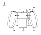
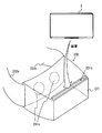
本体部は、第3対向面を有してもよい。第3対向面は、第1スライド部材の底面と対向し、第1レール部材が当該第1スライド部材に係合された第1ゲームコントローラの面のうち、第1レール部材が設けられる面の反対側の面の一部に沿って設けられる。 The main body may have a third facing surface. The third facing surface faces the bottom surface of the first slide member, and is opposite to the surface on which the first rail member is provided, of the surfaces of the first game controller in which the first rail member is engaged with the first slide member. It is provided along a part of the side surface.
支持装置は、第1弾性部材をさらに備えてもよい。第1弾性部材は、第3対向面に設けられ、第1レール部材が第1スライド部材に係合された第1ゲームコントローラに対して支持部の方向への力を加える。 The support device may further include a first elastic member. A 1st elastic member is provided in the 3rd opposing surface, and applies the force to the direction of a support part with respect to the 1st game controller with which the 1st rail member was engaged with the 1st slide member.
本体部は、第1グリップ部と第2グリップ部とを接続する接続部を有してもよい。 The main body part may have a connection part that connects the first grip part and the second grip part.
第1ゲームコントローラは、正面と、当該正面に対する側面であって第1レール部材が設けられる側面と、当該正面の反対側の裏面とを有してもよい。本体部は、第1レール部材が第1スライド部材に係合された第1ゲームコントローラの裏面の少なくとも一部に沿って設けられる面を有してもよい。 The first game controller may have a front surface, a side surface with respect to the front surface on which the first rail member is provided, and a back surface opposite to the front surface. The main body may have a surface provided along at least a part of the back surface of the first game controller in which the first rail member is engaged with the first slide member.
第1ゲームコントローラは、正面と、当該正面に対する側面であって第1レール部材が設けられる側面と、当該正面の反対側の裏面と、当該裏面に対して突出する操作部とを有してもよい。本体部には、第1スライド部材のスライド方向において第1ゲームコントローラが挿入される側の端部に、第1レール部材が当該第1スライド部材に係合された第1ゲームコントローラの操作部を避けるための切欠きが形成されてもよい。 The first game controller may include a front surface, a side surface with respect to the front surface on which the first rail member is provided, a back surface opposite to the front surface, and an operation unit that protrudes from the back surface. Good. The main body has an operation portion of the first game controller in which the first rail member is engaged with the first slide member at an end portion on the side where the first game controller is inserted in the sliding direction of the first slide member. Notches for avoidance may be formed.
第1ゲームコントローラは、正面と、当該正面に対する側面であって第1レール部材が設けられる第1側面と、当該第1側面の反対側の第2側面と、当該正面の反対側の裏面とを有してもよい。第2側面と裏面との接続部分は、丸みを帯びた曲面で形成されてもよい。本体部は、第1面と、第2面と、第3面とを有してもよい。第1面は、第1レール部材が第1スライド部材に対して係合された第1ゲームコントローラの第2側面に沿って設けられる。第2面は、第1面に連続し、第1レール部材が第1スライド部材に対して係合された第1ゲームコントローラの接続部分の曲面に沿って設けられる。第3面は、第2面に連続し、第1レール部材が第1スライド部材に対して係合された第1ゲームコントローラの裏面に沿って設けられる。 The first game controller includes a front surface, a first side surface which is a side surface with respect to the front surface and provided with a first rail member, a second side surface opposite to the first side surface, and a back surface opposite to the front surface. You may have. The connecting portion between the second side surface and the back surface may be formed with a rounded curved surface. The main body may have a first surface, a second surface, and a third surface. The first surface is provided along a second side surface of the first game controller in which the first rail member is engaged with the first slide member. The second surface is continuous with the first surface, and is provided along the curved surface of the connection portion of the first game controller in which the first rail member is engaged with the first slide member. The third surface is continuous with the second surface, and is provided along the back surface of the first game controller in which the first rail member is engaged with the first slide member.
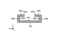
第1対向部は、第1スライド方向における一方側の端部に設けられ、当該第1スライド方向の他方側から挿入された第1レール部材と当接することによって当該第1レール部材のスライド移動を停止させてもよい。第2対向部は、第2スライド方向における一方側の端部に設けられ、当該第2スライド方向の他方側から挿入された第2レール部材と当接することによって当該第2レール部材のスライド移動を停止させてもよい。 The first facing portion is provided at an end portion on one side in the first sliding direction, and makes sliding movement of the first rail member by contacting the first rail member inserted from the other side in the first sliding direction. It may be stopped. The second facing portion is provided at an end portion on one side in the second sliding direction, and slides on the second rail member by contacting the second rail member inserted from the other side in the second sliding direction. It may be stopped.
第1スライド部材は、溝部と、2つの突出部とを有してもよい。溝部は、当該第1スライド部材の底面と、当該底面の両側にそれぞれ接続される各側面とによって形成される。突出部は、各側面からそれぞれ突出して設けられ、第1スライド部材の底面に対向する面を有する。 The first slide member may have a groove and two protrusions. The groove portion is formed by the bottom surface of the first slide member and the side surfaces respectively connected to both sides of the bottom surface. The protruding portion is provided so as to protrude from each side surface, and has a surface facing the bottom surface of the first slide member.
第1ゲームコントローラは、係止部材を有してもよい。係止部材は、第1レール部材が第1スライド部材に対して所定位置まで挿入された状態において、当該第1スライド部材に対する当該第1レール部材のスライド移動であって、当該第1スライド部材が当該第1レール部材に対して挿入される方向とは逆方向へのスライド移動を係止する。第1スライド部材は、被係止部を有してもよい。被係止部は、第1ゲームコントローラの第1レール部材が第1スライド部材に対して所定位置まで挿入された状態において係止部材が係止可能である。 The first game controller may have a locking member. The locking member is a sliding movement of the first rail member relative to the first slide member in a state in which the first rail member is inserted to a predetermined position with respect to the first slide member, and the first slide member The sliding movement in the direction opposite to the direction in which the first rail member is inserted is locked. The first slide member may have a locked portion. The locked member can be locked in a state where the first rail member of the first game controller is inserted to a predetermined position with respect to the first slide member.
第1スライド部材は、スライド方向における一方側の端部と他方側の端部とを有してもよい。第1端子は、第1スライド部材のスライド方向における第1スライド部材の中央よりも一方側の部分に設けられてもよい。被係止部は、第1スライド部材のスライド方向における第1スライド部材の中央よりも他方側の部分に設けられてもよい。 The first slide member may have an end on one side and an end on the other side in the sliding direction. The first terminal may be provided in a portion on one side of the center of the first slide member in the sliding direction of the first slide member. The locked portion may be provided on the other side of the center of the first slide member in the sliding direction of the first slide member.
第1スライド部材は、スライド方向における一方側の端部と他方側の端部とを有してもよい。第1ゲームコントローラは、第1スライド方向における第1スライド部材の他方側の端部に対して第1レール部材を挿入することによって、支持装置に対して装着されることが可能であってもよい。被係止部は、第1スライド部材の中央よりも他方側の部分に設けられてもよい。 The first slide member may have an end on one side and an end on the other side in the sliding direction. The first game controller may be capable of being attached to the support device by inserting the first rail member into the other end portion of the first slide member in the first slide direction. . The locked portion may be provided in a portion on the other side of the center of the first slide member.
第1スライド部材は、溝部と、2つの突出部とを有してもよい。溝部は、当該第1スライド部材の底面と、当該底面の両側にそれぞれ接続される各側面とによって形成される。突出部は、各側面からそれぞれ突出して設けられ、第1スライド部材の底面に対向する面を有する。被係止部は、2つの突出部のそれぞれに設けられてもよい。 The first slide member may have a groove and two protrusions. The groove portion is formed by the bottom surface of the first slide member and the side surfaces respectively connected to both sides of the bottom surface. The protruding portion is provided so as to protrude from each side surface, and has a surface facing the bottom surface of the first slide member. The locked portion may be provided on each of the two protruding portions.
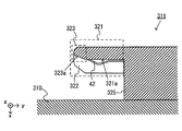
第1スライド部材の底面に入射口が設けられてもよい。第1スライド部材の底面とは異なる支持部の他の面に出射口が設けられてもよい。支持部は、入射口に対して入射された光を出射口まで導光する導光部をさらに備えてもよい。 An incident port may be provided on the bottom surface of the first slide member. The emission port may be provided on the other surface of the support portion different from the bottom surface of the first slide member. The support unit may further include a light guide unit that guides light incident on the entrance to the exit.
第1ゲームコントローラは、正面と、当該正面に対する側面であって第1レール部材が設けられる側面とを有してもよい。出射口は、支持部のうちで、第1レール部材が第1スライド部材に係合された第1ゲームコントローラの正面と同じ向きを向く面に設けられてもよい。 The first game controller may have a front surface and a side surface with respect to the front surface on which the first rail member is provided. The emission port may be provided on a surface of the support portion that faces the same direction as the front surface of the first game controller in which the first rail member is engaged with the first slide member.
導光部は、第1スライド部材の底面よりも凹んだ位置に設けられる入射面を有してもよい。 The light guide section may have an incident surface provided at a position recessed from the bottom surface of the first slide member.
第1スライド部材においては、第1レール部材と係合する部材の少なくとも一部と第1対向部とが一体的に形成されてもよい。 In the first slide member, at least a part of the member engaged with the first rail member and the first facing portion may be integrally formed.
第1スライド部材および第2スライド部材は、金属で構成されてもよい。 The first slide member and the second slide member may be made of metal.
第2スライド部材は、第2スライド方向が第1スライド方向と実質的に平行となる向きに設けられてもよい。 The second slide member may be provided in a direction in which the second slide direction is substantially parallel to the first slide direction.
第1対向部と第2対向部は、第1スライド方向および第2スライド方向において同じ側の端部に設けられてもよい。 The first facing portion and the second facing portion may be provided at the end on the same side in the first sliding direction and the second sliding direction.
支持装置は、第2弾性部材をさらに備えてもよい。第2弾性部材は、第1スライド部材の底面に設けられ、当該第1スライド部材に係合された第1レール部材に対して支持部から離れる方向への力を加える。 The support device may further include a second elastic member. The second elastic member is provided on the bottom surface of the first slide member, and applies a force in a direction away from the support portion to the first rail member engaged with the first slide member.
本発明の他の一例は、第1ゲームコントローラに対して充電を行うための充電装置である。第1ゲームコントローラは、当該第1ゲームコントローラを充電装置に装着するための第1レール部材を有する。
充電装置は、支持部と、第1スライド部材とを備える。第1スライド部材は、支持部のうちで所定方向における一方側の部分に設けられ、第1レール部材と所定の第1スライド方向にスライド可能に係合することが可能である。
第1スライド部材は、第1対向部と、第1端子とを有する。第1対向部は、支持部または第1スライド部材に設けられ、所定方向における他方側を向く第1対向面を有する。第1端子は、第1対向面に設けられる、第1ゲームコントローラと電気的に接続可能である。
充電装置は、コネクタと、給電制御部とを備える。コネクタは、支持部に設けられる。給電制御部は、コネクタを介して供給された電力を第1端子を介して第1ゲームコントローラへ供給することが可能である。
Another example of the present invention is a charging device for charging the first game controller. The first game controller has a first rail member for mounting the first game controller on the charging device.
The charging device includes a support portion and a first slide member. The first slide member is provided on one side of the support portion in a predetermined direction, and can engage with the first rail member so as to be slidable in a predetermined first slide direction.
The first slide member has a first facing portion and a first terminal. The first facing portion is provided on the support portion or the first slide member and has a first facing surface facing the other side in the predetermined direction. The first terminal can be electrically connected to a first game controller provided on the first facing surface.
The charging device includes a connector and a power supply control unit. The connector is provided on the support portion. The power supply control unit can supply the power supplied via the connector to the first game controller via the first terminal.
支持部は、給電制御部により第1ゲームコントローラに対して充電が行われていることを通知するために発光する発光部を含んでもよい。 The support unit may include a light emitting unit that emits light to notify the first game controller that charging is performed by the power supply control unit.
充電装置は、第1ゲームコントローラとは別の第2ゲームコントローラに対して充電を行うことが可能であってもよい。第2ゲームコントローラは、当該第2ゲームコントローラを充電装置に装着するための第2レール部材を有してもよい。
第1スライド部材は、支持部のうちで所定方向において一方側の部分に設けられてもよい。
充電装置は、第2スライド部材を備えてもよい。第2スライド部材は、支持部のうちで所定方向において他方側の部分に設けられ、第2レール部材と所定の第2スライド方向にスライド可能に係合することが可能である。
第2スライド部材は、第2対向部と、第2端子とを有してもよい。第2対向部は、支持部または第2スライド部材に設けられ、一方側を向く第2対向面を有する。第2端子は、第2対向面に設けられる、第2ゲームコントローラと電気的に接続可能である。
給電制御部は、コネクタを介して供給された電力を第1端子を介して第1ゲームコントローラへ供給するとともに、第2端子を介して第2ゲームコントローラへ供給することが可能である。
The charging device may be able to charge a second game controller different from the first game controller. The second game controller may have a second rail member for mounting the second game controller on the charging device.
The first slide member may be provided on one side of the support portion in a predetermined direction.
The charging device may include a second slide member. The second slide member is provided at a portion of the support portion on the other side in the predetermined direction, and can engage with the second rail member so as to be slidable in the predetermined second slide direction.
The second slide member may include a second facing portion and a second terminal. A 2nd opposing part is provided in a support part or a 2nd slide member, and has a 2nd opposing surface which faces one side. The second terminal can be electrically connected to a second game controller provided on the second facing surface.
The power supply control unit can supply the power supplied via the connector to the first game controller via the first terminal and can supply the second game controller via the second terminal.
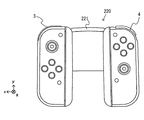
また、本発明の別の一例は、上記第1ゲームコントローラと、上記第2ゲームコントローラと、上記支持装置とを含む操作システムであってもよい。また、本発明の別の一例は、上記の支持装置または充電装置に装着可能な操作装置(例えば、上記ゲームコントローラ)であってもよいし、支持装置とゲームコントローラとを含む操作システムであってもよい。また、本発明の別の一例は、コントローラを装着可能な充電装置であってもよい。また、本発明の別の一例は、上記操作システムにおいて実行される方法であってもよい。 Another example of the present invention may be an operation system including the first game controller, the second game controller, and the support device. Further, another example of the present invention may be an operation device (for example, the game controller) that can be attached to the support device or the charging device, or an operation system including the support device and the game controller. Also good. Another example of the present invention may be a charging device to which a controller can be attached. Another example of the present invention may be a method executed in the operation system.
本発明によれば、支持装置が情報処理装置から外れる可能性を低減することが可能となる。 ADVANTAGE OF THE INVENTION According to this invention, it becomes possible to reduce possibility that a support apparatus will remove | deviate from information processing apparatus.
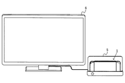
以下、本実施形態の一例に係る情報処理システム、情報処理装置、操作装置、および、付属機器について説明する。本実施形態においては、情報処理システムは、情報処理装置1と、クレードル5とを含む(図28参照)。本実施形態における情報処理装置1は、本体装置2とコントローラ3および4とが着脱可能であり、コントローラ3および4を本体装置2と別体として利用することができる(図2参照)。また、情報処理装置1は、本体装置2に画像を表示する態様と、テレビ等の他の表示装置に画像を表示させる態様との両方の利用態様が可能である。前者の態様において、情報処理装置1は、携帯型装置(例えば、携帯ゲーム機)として利用され、後者の態様において、情報処理装置1は、据置型装置(例えば、据置型ゲーム機)として利用される。
Hereinafter, an information processing system, an information processing device, an operation device, and an accessory device according to an example of the present embodiment will be described. In the present embodiment, the information processing system includes an
[1.システムの外観構成]
[1−1.情報処理装置の構成]
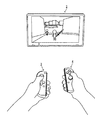
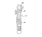
図1は、本実施形態における情報処理装置1の一例を示す図である。図1に示すように、情報処理装置1は、本体装置2と、左コントローラ3と、右コントローラ4とを含む。本体装置2は、ディスプレイ12を備え、情報処理装置1における各種の処理を実行する装置である。また、コントローラ3および4は、ユーザが入力を行うための操作部を備える装置である。
[1. System appearance configuration]
[1-1. Configuration of information processing apparatus]
FIG. 1 is a diagram illustrating an example of an
図2は、本体装置2から各コントローラ3および4を外した状態の一例を示す図である。図1および図2に示すように、各コントローラ3および4は、本体装置2に着脱可能である。左コントローラ3は、本体装置2の左側(図1に示すx軸正方向側)に装着することができる。右コントローラ4は、本体装置2の右側(図1に示すx軸負方向側)に装着することができる。なお、以下において、左コントローラおよび右コントローラの総称として「コントローラ」と記載することがある。以下、本体装置2および各コントローラ3および4の具体的な構成の一例について説明する。
FIG. 2 is a diagram illustrating an example of a state in which the
[1−1−1.本体装置の構成]
図3は、本体装置の一例を示す六面図である。図3に示すように、本体装置2は、略板状のハウジング11を備える。本実施形態において、ハウジング11の主面(換言すれば、表側の面、すなわち、ディスプレイ12が設けられる面)は、大略的には矩形形状である。本実施形態においては、ハウジング11は、横長の形状である。つまり、本実施形態においては、ハウジング11の主面の長手方向(すなわち、図1に示すx軸方向)を横方向(左右方向とも言う)とし、当該主面の短手方向(すなわち、図1に示すy軸方向)を縦方向(上下方向とも言う)とし、主面に垂直な方向(すなわち、図1に示すz軸方向)を奥行き方向(前後方向とも言う)とする。なお、本体装置2は、本体装置2が横長となる向きで利用されることも可能であるし、本体装置2が縦長となる向きで利用されることも可能である。
[1-1-1. Configuration of main unit]
FIG. 3 is a six-sided view illustrating an example of the main device. As shown in FIG. 3, the
なお、ハウジング11の形状および大きさは任意である。例えば、他の実施形態においては、ハウジング11は、ユーザが把持しやすくするための突起部やグリップ部を有していてもよい。
The shape and size of the
(ハウジング11の主面に設けられる構成)
図3に示すように、本体装置2は、ハウジング11の主面に設けられるディスプレイ12を備える。ディスプレイ12は、本体装置2が取得または生成した画像(静止画であってもよいし、動画であってもよい)を表示する。本実施形態においては、ディスプレイ12は液晶表示装置(LCD)であるとするが、任意の種類の表示装置であってよい。
(Configuration provided on the main surface of the housing 11)
As shown in FIG. 3, the
また、本体装置2は、ディスプレイ12の画面上にタッチパネル13を備える。タッチパネル13は、タッチ位置、タッチの圧力、および/または、タッチ入力に関する他の特性を検出してもよい。本実施形態においては、タッチパネル13は、マルチタッチ入力が可能な方式(例えば、静電容量方式)のものである。ただし、タッチパネル13は、任意の種類のものであってよく、例えば、シングルタッチ入力が可能な方式(例えば、抵抗膜方式)のものであってもよい。
The
本体装置2は、ハウジング11の内部においてスピーカ(すなわち、図30に示すスピーカ88)を備えている。図3に示すように、ハウジング11の主面にはスピーカ孔11aおよび11bが形成される。スピーカ88の出力音はこれらのスピーカ孔11aおよび11bから出力される。本実施形態では、本体装置2は2つのスピーカを備えており、左スピーカおよび右スピーカのそれぞれの位置に各スピーカ孔が設けられる。左スピーカ用のスピーカ孔11aは、ディスプレイ12の左側に形成される。右スピーカ用のスピーカ孔11bは、ディスプレイ12の右側に形成される。
The
また、本体装置2は、ハウジング11の内部において環境光センサ(すなわち、図30に示す環境光センサ94)を備えている。図3に示すように、ハウジング11の主面には、ハウジング11の外部の光を環境光センサ94に入力するための窓部14が設けられる。窓部14は、例えば、光を透過する透明な部材、あるいは、環境光センサ94が検知可能な所定波長の光を透過するフィルタ部材によって形成される。
The
なお、スピーカ孔11aおよび11b、ならびに、窓部14の位置、形状、および数は任意である。例えば、他の実施形態においては、各スピーカ孔11aおよび11bはハウジング11の側面あるいは背面に形成されてもよい。また、窓部14は、本実施形態においてはディスプレイ12よりも左下の位置に設けられるが、ハウジング11の主面における他の位置に設けられてもよいし、ハウジング11の側面に設けられてもよい。
In addition, the positions, shapes, and numbers of the speaker holes 11a and 11b and the
(ハウジング11の左側面に設けられる構成)
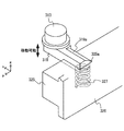
図3に示すように、本体装置2は、ハウジング11の左側面において左レール部材15を備える。左レール部材15は、左コントローラ3を本体装置2に着脱可能に装着するための部材である。ユーザは、左コントローラ3と本体装置2とを機械的および電気的に接続することを容易に行うことができ、左コントローラ3と本体装置2とを単一の装置のように機能させることができる。また、ユーザは、本体装置2から左コントローラ3を容易に外すことができ、左コントローラ3と本体装置2とを機械的に分離した状態で操作することができる。左レール部材15は、ハウジング11の左側面において、上下方向に沿って延びるように設けられる。左レール部材15は、左コントローラ3のスライダ(すなわち、図5に示すスライダ40)と係合可能な形状を有している。詳細は後述するが、左レール部材15とスライダ40とによってスライド機構が形成される。このスライド機構によって、左コントローラ3を本体装置2に対してスライド可能かつ着脱可能に装着することができる。
(Configuration provided on the left side surface of the housing 11)
As shown in FIG. 3, the
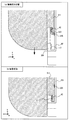
本実施形態においては、左レール部材15は、溝を有する形状である。換言すれば、左レール部材15の断面(具体的には、上下方向に垂直な断面)は、凹型の形状を有する。より具体的には、左レール部材15の断面は、断面の端部が外側から中央への方向を向く形状である。したがって、左レール部材15に係合したスライダ40は、スライド方向(換言すれば、左レール部材15が延びる方向)に垂直な向きに関しては固定されて外れないようになっている(後述する図7参照)。
In the present embodiment, the
図3に示すように、左レール部材15には、係合穴16が形成される。係合穴16は、左コントローラ3が本体装置2に装着された場合に、スライダ40に設けられる突起部41と対向する位置に設けられる。係合穴16の具体的な位置は任意である。本実施形態においては、係合穴16は、左レール部材15の底面(換言すれば、左レール部材15が有する溝の底面)に設けられる。また、係合穴16は、上記突起部(すなわち、図5に示す突起部41)が係合可能な形状に形成される。詳細は後述するが、左コントローラ3が本体装置2に装着された場合には、突起部41が係合穴16に挿入されて係合することによって、左コントローラ3が本体装置2に固定される。なお、他の実施形態においては、左レール部材15に突起部が設けられ、スライダ40に係合穴が設けられてもよい。
As shown in FIG. 3, an
また、本体装置2は左側端子17を備える。左側端子17は、本体装置2が左コントローラ3と有線通信を行うための端子である。つまり、左コントローラ3が本体装置2に装着された場合に、左コントローラ3および本体装置2は左側端子17を介して通信を行うことができる。左側端子17は、左コントローラ3が本体装置2に装着された場合に、左コントローラ3の端子(図5に示す端子42)と接触する位置に設けられる。左側端子17の具体的な位置は任意である。本実施形態においては、図3に示すように、左側端子17は、左レール部材15の底面に設けられる。また、本実施形態においては、左側端子17は、左レール部材15の底面における下側の端部付近に設けられる。左側端子17は、上記係合穴16よりも下側(換言すれば、左レール部材15にスライダ40を挿入する方向を基準としたときの奥側)に設けられる。
The
ハウジング11の左側面には、ストッパー18が設けられる。図3に示すように、ストッパー18は、左レール部材15の端部付近(本実施形態においては、下端付近)に設けられる。ストッパー18は、左レール部材15が有する溝の内部に設けられる。詳細は後述するが、ストッパー18は、左レール部材15に係合されたスライダ40のスライド移動を停止するために設けられる。
A
(ハウジング11の右側面に設けられる構成)
図3に示すように、ハウジング11の右側面には、左側面に設けられる構成と同様の構成が設けられる。すなわち、本体装置2は、ハウジング11の右側面において右レール部材19を備える。右レール部材19は、ハウジング11の右側面において、上下方向に沿って延びるように設けられる。右レール部材19は、右コントローラ4のスライダ(すなわち、図6に示すスライダ62)と係合可能な形状を有している。詳細は後述するが、右レール部材19とスライダ62とによってスライド機構が形成される。このスライド機構によって、右コントローラ4を本体装置2に対してスライド可能かつ着脱可能に装着することができる。
(Configuration provided on the right side surface of the housing 11)
As shown in FIG. 3, the right side surface of the
本実施形態においては、右レール部材19は、左レール部材15と同様の形状を有する。すなわち、右レール部材19は、左レール部材15と同様の断面形状となる溝を有する形状である。ただし、右レール部材19は、左レール部材15と全く同じ形状である必要はない。例えば、他の実施形態においては、右コントローラ4のスライダ62が左レール部材15に係合できないように(および/または、左コントローラ3のスライダ40が右レール部材19に係合できないように)、左レール部材15の溝と右レール部材19の溝とで大きさおよび/または形状が異なっていてもよい。
In the present embodiment, the
図3に示すように、右レール部材19には、係合穴20が形成される。係合穴20は、右コントローラ4が本体装置2に装着された場合に、スライダ62に設けられる突起部63と対向する位置に設けられる。係合穴20の具体的な位置は任意である。本実施形態においては、係合穴20は、右レール部材19の底面(換言すれば、右レール部材19が有する溝の底面)に設けられる。係合穴20は、上記突起部(すなわち、図6に示す突起部63)が係合可能な形状に形成される。詳細は後述するが、右コントローラ4が本体装置2に装着された場合には、突起部63が係合穴20に挿入されて係合することによって、右コントローラ4が本体装置2に固定される。なお、他の実施形態においては、右レール部材19に突起部が設けられ、スライダ62に係合穴が設けられてもよい。
As shown in FIG. 3, an
また、本体装置2は右側端子21を備える。右側端子21は、本体装置2が右コントローラ4と有線通信を行うための端子である。右側端子21は、右コントローラ4が本体装置2に装着された場合に、右コントローラ4の端子(図6に示す端子64)と接触する位置に設けられる。右側端子21の具体的な位置は任意である。本実施形態においては、図3に示すように、右側端子21は、右レール部材19の底面に設けられる。また、本実施形態においては、右側端子21は、右レール部材19の底面における下側の端部付近に設けられる。右側端子21は、上記係合穴20よりも下側(換言すれば、右レール部材19にスライダ62を挿入する方向を基準としたときの奥側)に設けられる。
The
ハウジング11の右側面には、ストッパー22が設けられる。図3に示すように、ストッパー22は、右レール部材19の端部付近(本実施形態においては、下端付近)に設けられる。ストッパー22は、右レール部材19が有する溝の内部に設けられる。詳細は後述するが、ストッパー22は、右レール部材19に係合されたスライダ62のスライド移動を停止するために設けられる。
A
上記のように、本実施形態においては、本体装置2のハウジング11には、左レール部材15および右レール部材19が設けられている。このように、ハウジング11は、コントローラを装着することを前提とした構成となっている。なお、上記各レール部材15および19の位置、形状、および大きさは任意である。例えば、他の実施形態においては、各レール部材15および19は、ハウジング11の主面および/または裏面における左右の端部にそれぞれ設けられてもよい。また、本体装置2と各コントローラ3および4を着脱可能に装着するための機構は任意であり、本実施形態におけるスライダ機構とは異なるスライダ機構が用いられてもよいし、スライダ機構とは異なる機構が用いられてもよい。
As described above, in the present embodiment, the
(ハウジング11の上側面に設けられる構成)
図3に示すように、本体装置2は第1スロット23を備える。第1スロット23は、ハウジング11の上側面に設けられる。第1スロット23は、第1の種類の記憶媒体を装着可能な形状を有する。なお、本実施形態においては、第1スロット23の開口部には開閉可能な蓋部が設けられており、蓋部を開けた状態において、第1スロット23に第1の種類の記憶媒体を挿入することができる。第1の種類の記憶媒体は、例えば、情報処理装置1およびそれと同種の情報処理装置に専用の記憶媒体(例えば、専用メモリカード)である。第1の種類の記憶媒体は、例えば、本体装置2で利用されるデータ(例えば、アプリケーションのセーブデータ等)、および/または、本体装置2で実行されるプログラム(例えば、アプリケーションのプログラム等)を記憶するために用いられる。
(Configuration provided on the upper surface of the housing 11)
As shown in FIG. 3, the
また、本体装置2は、電源ボタン28を備える。図3に示すように、電源ボタン28は、ハウジング11の上側面に設けられる。電源ボタン28は、本体装置2の電源のオン/オフを切り替えるためのボタンである。なお、本実施形態においては、電源ボタン28によって、オンモードとスリープモードとを切り替えることができるものとする。ここで、オンモードは、例えば、ディスプレイ12の画面表示が行われるモードであり、スリープモードは、例えば、ディスプレイ12の画面表示が休止されるモードである。また、スリープモードにおいては、ディスプレイ12の画面表示が休止されることとともに(または代えて)、実行中のアプリケーションにおける所定の処理(例えば、ゲームアプリケーションにおけるゲーム処理)が休止されてもよい。本体装置2は、電源ボタン24に対して長押し操作が行われた場合(具体的には、電源ボタン24が所定時間以上押下し続けられた場合)、本体装置2の電源のオン/オフを切り替える処理を実行する。一方、電源ボタン24に対して短押し操作が行われた場合(具体的には、電源ボタン24が上記所定時間よりも短い時間だけ押下された場合)、本体装置2は、オンモードとスリープモードとを切り替える処理を実行する。
The
上記のように、本実施形態においては、電源ボタン28は、電源のオン/オフの切り替えと、オンモードとスリープモードの切り替えとを行うことができる。なお、他の実施形態においては、電源のオン/オフの切り替えの切り替え機能のみ、あるいは、オンモードとスリープモードの切り替え機能のみを有するボタンが本体装置2に設けられてもよい。
As described above, in the present embodiment, the
本体装置2は、音声入出力端子(具体的には、イヤホンジャック)25を備える。すなわち、本体装置2は、音声入出力端子25にマイクやイヤホンを装着することができる。図3に示すように、音声入出力端子25は、ハウジング11の上側面に設けられる。
The
本体装置2は、音量ボタン26aおよび26bを備える。図3に示すように、音量ボタン26aおよび26bは、ハウジング11の上側面に設けられる。音量ボタン26aおよび26bは、本体装置2によって出力される音量を調整する指示を行うためのボタンである。すなわち、音量ボタン26aは、音量を下げる指示を行うためのボタンであり、音量ボタン26bは、音量を上げる指示を行うためのボタンである。
The
また、ハウジング11には、排気孔11cが形成される。図3に示すように、排気孔11cは、ハウジング11の上側面に形成される。排気孔11cは、ハウジング11の内部で発生した熱をハウジング11の外部へ排気する(換言すれば、放出する)ために形成される。
The
(ハウジング11の下側面に設けられる構成)
本体装置2は下側端子27を備える。下側端子27は、本体装置2が、後述するクレードル5と通信を行うための端子である。図3に示すように、下側端子27は、ハウジング11の下側面に設けられる。詳細は後述するが、本体装置2がクレードル5に装着された場合に、下側端子27は、クレードル5の端子(図29に示す本体端子73)に接続される。本実施形態において、下側端子27は、USBコネクタ(より具体的には、メス側コネクタ)である。
(Configuration provided on the lower surface of the housing 11)
The
また、本体装置2は第2スロット24を備える。本実施形態においては、第2スロット24は、ハウジング11の下側面に設けられる。ただし、他の実施形態においては、第2スロット24は第1スロット23とは同じ面に設けられてもよい。第2スロット24は、第1の種類とは異なる第2の種類の記憶媒体を装着可能な形状を有する。なお、本実施形態においては、第2スロット24の開口部には開閉可能な蓋部が設けられており、蓋部を開けた状態において、第2スロット24に第2の種類の記憶媒体を挿入することができる。第2の種類の記憶媒体は、例えば、汎用の記憶媒体であってもよく、例えば、SDカードであってもよい。第2の種類の記憶媒体は、例えば、第1の種類の記憶媒体と同様、本体装置2で利用されるデータ(例えば、アプリケーションのセーブデータ等)、および/または、本体装置2で実行されるプログラム(例えば、アプリケーションのプログラム等)を記憶するために用いられる。
The
また、ハウジング11には、吸気孔11dが形成される。図3に示すように、吸気孔11dは、ハウジング11の下側面に形成される。吸気孔11dは、ハウジング11の外部の空気をハウジング11の内部へ吸気する(換言すれば、導入する)ために形成される。本実施形態においては、排気孔11cが形成される面の反対側の面に吸気孔11dが形成されるので、ハウジング11内部の放熱を効率良く行うことができる。
The
また、本体装置2は、ハウジングを立てて載置するためのスタンド部材29を備える。図3に示すように、スタンド部材29は、ハウジング11の下側面に設けられる。スタンド部材29は、軸部29aでハウジング11に対して回転可能に接続されている。図3においては、スタンド部材29はハウジング11に収納された状態である。
The
図4は、本体装置2を立てて載置した様子の一例を示す図である。なお、図4においては、本図を用いて説明するポイント部分の構成を見やすくする目的で、本体装置2における当該構成以外の他のいくつかの構成については省略して表している。ここで、上記スタンド部材29の棒状の部分は、軸部29aを軸として回転することによって、ハウジング11から突出した状態となる。したがって、スタンド部材29をハウジング11から突出した状態とすることによって、図4に示すように、本体装置2を立てて載置することができる。なお、本体装置2を立てて載置するための機構は、図3に示すスタンド部材29に限らず、任意である。
FIG. 4 is a diagram illustrating an example of a state in which the
以上に説明した、ハウジング11に設けられる各構成要素(具体的には、ボタン、スロット、端子等)の形状、数、および、設置位置は任意である。例えば、他の実施形態においては、電源ボタン28および各スロット23および24のうちのいくつかは、ハウジング11の他の側面あるいは背面に設けられてもよい。また、他の実施形態においては、本体装置2は、上記各構成要素のうちいくつかを備えていない構成であってもよい。
The shape, number, and installation position of each component (specifically, button, slot, terminal, etc.) provided in the
[1−1−2.左コントローラの構成]
図5は、左コントローラ3の一例を示す六面図である。図5に示すように、左コントローラ3は、略板状のハウジング31を備える。本実施形態において、ハウジング31の主面(換言すれば、表側の面、すなわち、図1に示すz軸負方向側の面)は、大略的には矩形形状である。また、本実施形態においては、ハウジング31は、縦長の形状、すなわち、上下方向(すなわち、図1に示すy軸方向)に長い形状である。なお、左コントローラ3は、本体装置2から外された状態において、縦長となる向きで把持されることも可能であるし(図38参照)、横長となる向きで把持されることも可能である(図35参照)。なお、ハウジング31の形状は任意であり、他の実施形態においては、ハウジング31は略板状でなくてもよい。また、ハウジング31は、矩形形状でなくてもよく、例えば半円状の形状等であってもよい。また、ハウジング31は、縦長の形状でなくてもよい。
[1-1-2. Left controller configuration]
FIG. 5 is a six-sided view illustrating an example of the
ハウジング31の上下方向の長さは、本体装置2のハウジング11の上下方向の長さとほぼ同じである。また、ハウジング31の厚さ(すなわち、前後方向の長さ、換言すれば、図1に示すz軸方向の長さ)は、本体装置2のハウジング11の厚さとほぼ同じである。したがって、左コントローラ3が本体装置2に装着された場合(図1参照)には、ユーザは、本体装置2と左コントローラ3とを一体の装置のような感覚で把持することができる。
The vertical length of the
また、図5に示すように、ハウジング31の主面は、左側の角部分が、右側の角部分よりも丸みを帯びた形状になっている。すなわち、ハウジング31の上側面と左側面との接続部分、および、ハウジング31の下側面と左側面との接続部分は、その上側面と右側面との接続部分、および、その下側面と右側面との接続部分に比べて、丸くなっている(換言すれば、面取りにおけるRが大きい)。したがって、左コントローラ3が本体装置2に装着された場合(図1参照)には、情報処理装置1の左側が丸みを帯びた形状となるので、ユーザにとって持ちやすい形状となる。
Further, as shown in FIG. 5, the main surface of the
左コントローラ3は、アナログスティック32を備える。図5に示すように、アナログスティック32は、ハウジング31の主面に設けられる。アナログスティック32は、方向を入力することが可能な方向入力部の一例である。アナログスティック32は、ハウジング31の主面に平行な全方向(すなわち、上下左右および斜め方向を含む、360°の方向)に傾倒可能なスティック部材を有する。ユーザは、スティック部材を傾倒することによって傾倒方向に応じた方向の入力(および、傾倒した角度に応じた大きさの入力)が可能である。なお、方向入力部は、十字キーまたはスライドスティック等であってもよい。スライドスティックは、ハウジング31の主面に平行な全方向にスライド可能なスティック部材を有する入力部であり、ユーザは、スティック部材をスライドすることによってスライド方向に応じた入力(および、スライド量に応じた大きさの入力)が可能である。また、本実施形態においては、スティック部材を(ハウジング31に垂直な方向に)押下する入力が可能である。すなわち、アナログスティック32は、スティック部材の傾倒方向および傾倒量に応じた方向および大きさの入力と、スティック部材に対する押下入力とを行うことが可能な入力部である。
The
左コントローラ3は、4つの操作ボタン33〜36(具体的には、右方向ボタン33、下方向ボタン34、上方向ボタン35、および、左方向ボタン36)を備える。図5に示すように、これら4つの操作ボタン33〜36は、ハウジング31の主面においてアナログスティック32の下側に設けられる。なお、本実施形態においては、左コントローラ3の主面に設けられる操作ボタンを4つとするが、操作ボタンの数は任意である。これらの操作ボタン33〜36は、本体装置2で実行される各種プログラム(例えば、OSプログラムやアプリケーションプログラム)に応じた指示を行うために用いられる。なお、本実施形態においては、各操作ボタン33〜36は方向入力を行うために用いられてもよいことから、各操作ボタン33〜36を、右方向ボタン33、下方向ボタン34、上方向ボタン35、および、左方向ボタン36と呼んでいる。ただし、各操作ボタン33〜36は、方向入力以外の指示を行うために用いられてもよい。
The
また、左コントローラ3は録画ボタン37を備える。図5に示すように、録画ボタン37は、ハウジング31の主面に設けられ、より具体的には、主面における右下領域に設けられる。録画ボタン37は、本体装置2のディスプレイ12に表示される画像を保存する指示を行うためのボタンである。例えば、ディスプレイ12にゲーム画像が表示されている場合において、ユーザは、録画ボタン37を押下することによって、押下された時点で表示されているゲーム画像を、例えば本体装置2の記憶部に保存することができる。
The
また、左コントローラ3は−(マイナス)ボタン47を備える。図5に示すように、−ボタン47は、ハウジング31の主面に設けられ、より具体的には、主面における右上領域に設けられる。−ボタン47は、本体装置2で実行される各種プログラム(例えば、OSプログラムやアプリケーションプログラム)に応じた指示を行うために用いられる。−ボタン47は、例えば、ゲームアプリケーションにおいてセレクトボタン(例えば、選択項目の切り替えに用いられるボタン)として用いられる。
The
左コントローラ3の主面に設けられる各操作部(具体的には、アナログスティック32および上記各ボタン33〜37,47)は、左コントローラ3が本体装置2に装着される場合、情報処理装置1を把持するユーザの例えば左手の親指によって操作される(図33参照)。また、左コントローラ3が本体装置2から外された状態で使用される場合、上記各操作部は、左コントローラ3を把持するユーザの例えば左右の手の親指で操作される(図34参照)。具体的には、この場合、アナログスティック32はユーザの左手の親指で操作され、各操作ボタン33〜36はユーザの右手の親指で操作される。
The operation units (specifically, the
左コントローラ3は第1Lボタン38を備える。また、左コントローラ3はZLボタン39を備える。これらの操作ボタン38および39は、上記操作ボタン33〜36と同様、本体装置2で実行される各種プログラムに応じた指示を行うために用いられる。図5に示すように、第1Lボタン38は、ハウジング31の側面のうちの左上部分に設けられる。また、ZLボタン39は、ハウジング31の側面から裏面にかけての左上部分(厳密には、ハウジング31を表側から見たときの左上部分)に設けられる。つまり、ZLボタン39は、第1Lボタン38の後側(図1に示すz軸正方向側)に設けられる。本実施形態においては、ハウジング31の左上部分が丸みを帯びた形状であるので、第1Lボタン38およびZLボタン39は、ハウジング31の当該左上部分の丸みに応じた丸みを帯びた形状を有する。
The
左コントローラ3が本体装置2に装着される場合、第1Lボタン38およびZLボタン39は、情報処理装置1における左上部分に配置されることになる(図1参照)。したがって、情報処理装置1を把持するユーザは、左手の人差し指や中指で第1Lボタン38およびZLボタン39を操作することができる(図33参照)。
When the
図5に示すように、ハウジング31の裏面のうちでZLボタン39が設けられる部分(より具体的には、ZLボタン39の周囲の少なくとも一部)は、ハウジング31の他の部分に比べて突起している。また、ZLボタン39は、ハウジング31の裏面における当該他の部分に対して突起して設けられる。したがって、左コントローラ3が装着された本体装置2を、左コントローラ3の裏面が水平な載置面に対向する向きで載置面に載置した場合、ハウジング31の突起した部分が載置面に当接する。その結果、情報処理装置1は、本体装置2の上側が下側よりもやや高くなるように載置される。上記のように情報処理装置1が載置された場合、ユーザにとってはディスプレイ12が見やすくなる。
As shown in FIG. 5, a portion of the rear surface of the
なお、他の実施形態においては、左コントローラ3が装着された本体装置2を、左コントローラ3の裏面が水平な載置面に対向する向きで載置面に載置した場合、ZLボタン39が載置面に当接してもよい。ここで、本実施形態においては、ZLボタン39は、主に上下方向(y軸方向)に押下可能である。つまり、ZLボタン39は、主に上下方向に移動するようにハウジング31に対して支持される。したがって、上記のようにZLボタン39が載置面に当接するように情報処理装置1が載置された場合であっても、ZLボタン39には主に前後方向(z軸方向)に力が加わるので、ZLボタン39は押下されにくい。つまり、情報処理装置1が上記のように載置された場合であっても、ZLボタン39が誤って押下される可能性が小さい。
In another embodiment, when the
また、他の実施形態においては、ZLボタン39は、ハウジング31の裏面から突起しないように形成されてもよい。例えば、ZLボタン39は、ハウジング31の側面に設けられてもよい。また例えば、ハウジング31の裏面のうちでZLボタン39が設けられる部分が他の部分に比べて凹んで形成される(すなわち、他の部分よりも薄く形成される)ことによって、ZLボタン39が当該他の部分よりも突起しないように形成されてもよい。
In other embodiments, the
左コントローラ3は、上述のスライダ40を備えている。図5に示すように、スライダ40は、ハウジング31の右側面において、上下方向に延びるように設けられる。スライダ40は、本体装置2の左レール部材15(より具体的には、左レール部材15の溝)と係合可能な形状を有している。具体的には、スライダ40の断面(具体的には、上下方向に垂直な断面)は、凸型の形状を有する。より具体的には、スライダ40の断面は、左レール部材15の断面形状に応じたT字形状を有する(図7参照)。したがって、左レール部材15に係合したスライダ40は、スライド方向(換言すれば左レール部材15が延びる方向)に垂直な向きに関しては固定されて外れないようになっている(後述する図7参照)。
The
また、図5に示すように、スライダ40には、突起部41が設けられる。突起部41は、左コントローラ3が本体装置2に装着された場合に、上記係合穴16に挿入される位置に配置される。突起部41の具体的な位置は任意である。本実施形態においては、突起部41は、スライダ40の装着面に設けられる。なお、スライダ40の装着面とは、左コントローラ3が本体装置2に装着された場合に左レール部材15の底面に対向する面である。また、突起部41は、左レール部材15の係合穴16に係合可能な形状に形成される。
As shown in FIG. 5, the
本実施形態においては、突起部41は、スライダ40の内部側から外部側に向けて付勢されている。したがって、突起部41に対してスライダ40の外部側から内部側への力を加えることで、突起部41はスライダ40の内部に向けて移動する(すなわち、スライダ40の内側へ引っ込む)。上記のように突起部41を付勢するための構成は任意である。例えば、本実施形態においては、突起部41は、スライダ40の内部において弾性体に接続されており、スライダ40に形成された孔から突起部41の一部がスライダ40の装着面に対して突出した状態で配置されている。なお、他の実施形態においては、突起部41はスライダ40に対して固定的に設けられてもよい。
In the present embodiment, the
また、左コントローラ3は、左コントローラ3が本体装置2と有線通信を行うための端子42を備える。端子42は、左コントローラ3が本体装置2に装着された場合に、本体装置2の左側端子17(図3)と接触する位置に設けられる。端子42の具体的な位置は任意である。本実施形態においては、図5に示すように、端子42は、スライダ40の装着面に設けられる。また、本実施形態においては、端子42は、スライダ40の装着面における下側の端部付近に設けられる。端子42は、上記突起部41よりも下側(換言すれば、スライダ40を左レール部材15に挿入する場合における先端側)に設けられる。
The
また、左コントローラ3は、第2Lボタン43および第2Rボタン44を備える。これらのボタン43および44は、他の操作ボタン33〜36と同様、本体装置2で実行される各種プログラムに応じた指示を行うために用いられる。図5に示すように、第2Lボタン43および第2Rボタン44は、スライダ40の装着面に設けられる。第2Lボタン43は、スライダ40の装着面において、上下方向(図1に示すy軸方向)に関する中央よりも上側に設けられる。第2Rボタン44は、スライダ40の装着面において、上下方向に関する中央よりも下側に設けられる。第2Lボタン43および第2Rボタン44は、左コントローラ3が本体装置2に装着されている状態では押下することができない位置に配置されている。つまり、第2Lボタン43および第2Rボタン44は、左コントローラ3を本体装置2から外した場合において用いられるボタンである。第2Lボタン43および第2Rボタン44は、例えば、本体装置2から外された左コントローラ3を把持するユーザの左右の手の人差し指または中指で操作される(図35参照)。
The
左コントローラ3は、通知用LED45を備える。通知用LED45は、ユーザに対して所定の情報を通知するための通知部である。通知用LED45によって通知される情報は任意である。本実施形態においては、通知用LED45は、本体装置2が複数のコントローラと通信を行う場合に、各コントローラを識別する情報をユーザに示す。具体的には、左コントローラ3は、通知用LED45として、本体装置2が同時に通信可能な左コントローラの数(ここでは、4つ)のLEDを備える。そして、4つのLEDのうち、そのコントローラに付された番号に応じたLEDが点灯する。これによれば、通知用LED45によって上記番号をユーザに通知することができる。
The
他の実施形態においては、通知用LED45は、左コントローラ3と本体装置2との通信に関する状態をユーザに通知してもよい。例えば、本体装置2との通信が確立している場合に通知用LED45が点灯してもよい。また、本実施形態においては、通知用LED45として機能するLED(換言すれば、発光部)の数を4つとするが、当該LEDの数は任意である。
In another embodiment, the
本実施形態においては、通知用LED45は、図5に示すように、スライダ40の装着面に設けられる。このように、通知用LED45は、左コントローラ3が本体装置2に装着されている状態では見えない位置に配置されている。つまり、通知用LED45は、左コントローラ3を本体装置2から外した場合において用いられる。
In the present embodiment, the
左コントローラ3は、ペアリングボタン46を備える。本実施形態において、ペアリングボタン46は、左コントローラ3と本体装置2との無線通信に関する設定(ペアリングとも言う)処理を指示するため、および、左コントローラ3のリセット処理を指示するために用いられる。なお、他の実施形態においては、ペアリングボタン46は、上記設定処理およびリセット処理のいずれか一方の機能のみを有するものであってもよい。
The
すなわち、ペアリングボタン46に対して短押し操作が行われた場合(具体的には、ペアリングボタン46が所定時間よりも短い時間だけ押下された場合)、左コントローラ3は、上記設定処理を実行する。なお、上記設定処理の詳細については後述する。
That is, when a short press operation is performed on the pairing button 46 (specifically, when the
また、ペアリングボタン46に対して長押し操作が行われた場合(具体的には、ペアリングボタン46が上記所定時間以上押し続けられた場合)、左コントローラ3は、リセット処理を実行する。リセット処理は、左コントローラ3の状態をリセットする処理であり、例えば左コントローラ3がフリーズした場合(例えば、本体装置2が左コントローラ3からのデータを取得できなくなった場合等)に実行すべき処理である。リセット処理の具体的な内容は任意であるが、リセット処理は、例えば、左コントローラ3の電源を一端オフにして再度オンにする処理、本体装置2との通信を一端切断して再開する処理、通信開始時に実行する処理を再度実行する処理、および/または、上記設定処理であってもよい。上記ペアリングボタン46によって、本実施形態においては、左コントローラ3が何らかの理由でフリーズした場合であっても、左コントローラ3を利用可能な状態にリセットすることができる。
Further, when a long press operation is performed on the pairing button 46 (specifically, when the
本実施形態においては、ペアリングボタン46は、図5に示すように、スライダ40の装着面に設けられる。このように、ペアリングボタン46は、左コントローラ3が本体装置2に装着されている状態では見えない位置に配置されている。つまり、ペアリングボタン46は、左コントローラ3を本体装置2から外した場合において用いられる。本実施形態においては、ペアリングボタン46は、左コントローラ3を本体装置2から外した状態で押下されると想定され、左コントローラ3が本体装置2に装着される状態では押下される可能性は低いと想定される。そのため、左コントローラ3が本体装置2に装着される状態でペアリングボタン46が誤操作されることを抑止するべく、ペアリングボタン46は上記の位置に配置される。
In the present embodiment, the
なお、本実施形態において、スライダ40の装着面に設けられるボタン(具体的には、第2Lボタン43、第2Rボタン44、およびペアリングボタン46)は、当該装着面に対して突出しないように設けられる。すなわち、上記ボタンの上面(換言すれば押下面)は、スライダ40の装着面と同じ面に配置されるか、あるいは、装着面よりも凹んだ位置に配置される。これによれば、スライダ40が本体装置2の左レール部材15に装着された状態において、スライダ40を左レール部材15に対してスムーズにスライドさせることができる。
In the present embodiment, the buttons (specifically, the
[1−1−3.右コントローラの構成]
図6は、右コントローラ4の一例を示す六面図である。図6に示すように、右コントローラ4は、略板状のハウジング51を備える。本実施形態において、ハウジング51の主面(換言すれば、表側の面、すなわち、図1に示すz軸負方向側の面)は、大略的には矩形形状である。また、本実施形態においては、ハウジング51は、縦長の形状、すなわち、上下方向に長い形状である。なお、右コントローラ4は、本体装置2から外された状態において、縦長となる向きで把持されることも可能であるし(図38参照)、横長となる向きで把持されることも可能である(図35参照)。
[1-1-3. Right controller configuration]
FIG. 6 is a six-sided view illustrating an example of the
右コントローラ4のハウジング51は、左コントローラ3のハウジング31と同様、その上下方向の長さは、本体装置2のハウジング11の上下方向の長さとほぼ同じであり、その厚さは、本体装置2のハウジング11の厚さとほぼ同じである。したがって、右コントローラ4が本体装置2に装着された場合(図1参照)には、ユーザは、本体装置2と右コントローラ4とを一体の装置のような感覚で把持することができる。
Like the
また、図6に示すように、ハウジング51の主面は、右側の角部分が、左側の角部分よりも丸みを帯びた形状になっている。すなわち、ハウジング51の上側面と右側面との接続部分、および、ハウジング51の下側面と右側面との接続部分は、その上側面と左側面との接続部分、および、その下側面と左側面との接続部分に比べて、丸くなっている(換言すれば、面取りにおけるRが大きい)。したがって、右コントローラ4が本体装置2に装着された場合(図1参照)には、情報処理装置1の右側が丸みを帯びた形状となるので、ユーザにとって持ちやすい形状となる。
As shown in FIG. 6, the main surface of the
右コントローラ4は、左コントローラ3と同様、方向入力部としてアナログスティック52を備える。本実施形態においては、アナログスティック52は、左コントローラ3のアナログスティック32と同じ構成である。また、右コントローラ4は、左コントローラ3と同様、4つの操作ボタン53〜56(具体的には、Aボタン53、Bボタン54、Xボタン55、および、Yボタン56)を備える。本実施形態においては、これら4つの操作ボタン53〜56は、左コントローラ3の4つの操作ボタン33〜36と同じ機構である。図6に示すように、これらアナログスティック52および各操作ボタン53〜56は、ハウジング51の主面に設けられる。なお、本実施形態においては、右コントローラ4の主面に設けられる操作ボタンを4つとするが、操作ボタンの数は任意である。
Similar to the
ここで、本実施形態においては、右コントローラ4における2種類の操作部(アナログスティックおよび操作ボタン)の位置関係は、左コントローラ3におけるこれら2種類の操作部の位置関係とは反対になっている。すなわち、右コントローラ4においては、アナログスティック52は各操作ボタン53〜56の上方に配置されるのに対して、左コントローラ3においては、アナログスティック32は各操作ボタン33〜36の下方に配置される。詳細は後述するが、このような配置によって、左右のコントローラ3および4を本体装置2から外して使用する場合に似たような操作感覚で使用することができる。
Here, in the present embodiment, the positional relationship between the two types of operation units (analog stick and operation button) in the
また、右コントローラ4は、+(プラス)ボタン57を備える。図6に示すように、+ボタン57は、ハウジング51の主面に設けられ、より具体的には、主面の左上領域に設けられる。+ボタン57は、他の操作ボタン53〜56と同様、本体装置2で実行される各種プログラム(例えば、OSプログラムやアプリケーションプログラム)に応じた指示を行うために用いられる。+ボタン57は、例えば、ゲームアプリケーションにおいてスタートボタン(例えば、ゲーム開始の指示に用いられるボタン)として用いられる。
The
右コントローラ4は、ホームボタン58を備える。図6に示すように、ホームボタン58は、ハウジング51の主面に設けられ、より具体的には、主面の左下領域に設けられる。ホームボタン58は、本体装置2のディスプレイ12に所定のメニュー画面を表示させるためのボタンである。メニュー画面は、例えば、本体装置2において実行可能な1以上のアプリケーションのうちからユーザが指定したアプリケーションを起動することが可能な画面である。メニュー画面は、例えば、本体装置2の起動時に表示されてもよい。本実施形態においては、本体装置2においてアプリケーションが実行されている状態(すなわち、当該アプリケーションの画像がディスプレイ12に表示されている状態)において、ホームボタン58が押下されると、所定の操作画面がディスプレイ12に表示されてもよい(このとき、操作画面に代えてメニュー画面が表示されてもよい)。なお、操作画面は、例えば、アプリケーションを終了してメニュー画面をディスプレイ12に表示させる指示、および、アプリケーションを再開する指示等を行うことが可能な画面である。
The
右コントローラ4の主面に設けられる各操作部(具体的には、アナログスティック52および上記各ボタン53〜59)は、右コントローラ4が本体装置2に装着される場合、情報処理装置1を把持するユーザの例えば右手の親指によって操作される(図33参照)。また、右コントローラ4が本体装置2から外された状態で使用される場合、上記各操作部は、右コントローラ4を把持するユーザの例えば左右の手の親指で操作される(図34参照)。具体的には、この場合、アナログスティック52はユーザの左手の親指で操作され、各操作ボタン53〜56はユーザの右手の親指で操作される。
Each operation unit (specifically, the
右コントローラ4は第1Rボタン60を備える。また、右コントローラ4はZRボタン61を備える。図6に示すように、第1Rボタン60は、ハウジング51の側面のうちの右上部分に設けられる。また、ZRボタン61は、ハウジング51の側面から裏面にかけての右上部分(厳密には、ハウジング51を表側から見たときの右上部分)に設けられる。つまり、ZRボタン61は、第1Rボタン60の後側(図1に示すz軸正方向側)に設けられる。本実施形態においては、ハウジング51の右上部分が丸みを帯びた形状であるので、第1Rボタン60およびZRボタン61は、ハウジング51の当該右上部分の丸みに応じた丸みを帯びた形状を有する。
The
右コントローラ4が本体装置2に装着される場合、第1Rボタン60およびZRボタン61は、情報処理装置1における右上部分に配置されることになる(図1参照)。したがって、情報処理装置1を把持するユーザは、右手の人差し指や中指で第1Rボタン60およびZRボタン61を操作することができる(図34参照)。
When the
図6に示すように、右コントローラ4におけるZRボタン61は、左コントローラ3におけるZLボタン39と同様、ハウジング51から突起して設けられる。すなわち、ハウジング51の裏面のうちでZRボタン61が設けられる部分(より具体的には、ZRボタン61の周囲の少なくとも一部)は、ハウジング51の他の部分に比べて突起している。また、ZRボタン61は、ハウジング51の裏面における当該他の部分に対して突起して設けられる。したがって、右コントローラ4が本体装置2に装着される場合も、左コントローラ3が本体装置2に装着される場合と同様、右コントローラ4の裏面が水平な載置面に対向する向きで本体装置2を載置面に載置すると、ハウジング51の突起した部分が載置面に当接する。その結果、本体装置2の上側が下側よりもやや高くなるように載置されるので、ユーザにとってはディスプレイ12が見やすくなる。
As shown in FIG. 6, the
なお、本実施形態においては、右コントローラ4におけるZRボタン61は、左コントローラ3におけるZLボタン39と同様、主に上下方向(y軸方向)に押下可能である。したがって、ZRボタン61が載置面に当接するように情報処理装置1が載置された場合であっても、ZLボタン39と同様に、ZRボタン61は押下されにくく、誤って押下される可能性が小さい。なお、他の実施形態においては、ハウジング51の裏面がZRボタン61よりも突起するようにハウジング51が形成されてもよい。また、他の実施形態においては、ZRボタン61は、左コントローラ3におけるZLボタン39と同様、ハウジング51の裏面から突起しないように形成されてもよい。
In the present embodiment, the
また、本実施形態においては、第1Lボタン38の形状と第1Rボタン60の形状とは左右対称にはならず、ZLボタン39の形状とZRボタン61の形状とは左右対称の形状にはなっていない。ただし、他の実施形態においては、第1Lボタン38の形状と第1Rボタン60の形状とは左右対称であってもよく、ZLボタン39の形状とZRボタン61の形状とは左右対称であってもよい。
Further, in the present embodiment, the shape of the
右コントローラ4は、左コントローラ3と同様のスライダ機構を備えている。すなわち、右コントローラ4は、上述のスライダ62を備えている。図6に示すように、スライダ62は、ハウジング51の左側面において、上下方向に延びるように設けられる。スライダ62は、本体装置2の右レール部材19(より具体的には、右レール部材19の溝)と係合可能な形状を有している。具体的には、スライダ62の断面(具体的には、上下方向に垂直な断面)は、凸型の形状を有する。より具体的には、スライダ62の断面は、右レール部材19の断面形状に応じたT字形状を有する(図7参照)。したがって、右レール部材19に係合したスライダ62は、スライド方向(換言すれば右レール部材19が延びる方向)に垂直な向きに関しては固定されて外れないようになっている(図7参照)。
The
また、スライダ62には、突起部63が設けられる。突起部63は、右コントローラ4が本体装置2に装着された場合に、上記係合穴20に挿入される位置に配置される。突起部63の具体的な位置は任意である。本実施形態においては、突起部63は、スライダ62の装着面に設けられる。なお、スライダ62の装着面とは、右コントローラ4が本体装置2に装着された場合に右レール部材19の底面に対向する面である。また、突起部63は、右レール部材19の係合穴20に係合可能な形状に形成される。
The
本実施形態においては、右コントローラ4の突起部63は、左コントローラ3の突起部41と同様、スライダ62の内部側から外部側に向けて付勢されている。したがって、突起部63に対してスライダ62の外部側から内部側への力を加えることで、突起部63はスライダ62の内部に向けて移動する(すなわち、スライダ62の内側へ引っ込む)。なお、上記のように突起部63を付勢するための構成は任意であり、上記左コントローラ3の突起部41と同様の構成であってもよい。
In the present embodiment, the
また、右コントローラ4は、右コントローラ4が本体装置2と有線通信を行うための端子64を備える。端子64は、右コントローラ4が本体装置2に装着された場合に、本体装置2の右側端子21(図3)と接触する位置に設けられる。端子64の具体的な位置は任意である。本実施形態においては、図6に示すように、端子64は、スライダ62の装着面に設けられる。本実施形態においては、端子64は、スライダ62の装着面における下側の端部付近に設けられる。端子64は、上記突起部63よりも下側(換言すれば、スライダ62を右レール部材19に挿入する場合における先端側)に設けられる。
The
また、右コントローラ4は、左コントローラ3と同様、第2Lボタン65および第2Rボタン66を備える。これらのボタン65および66は、他の操作ボタン53〜56と同様、本体装置2で実行される各種プログラムに応じた指示を行うために用いられる。図6に示すように、第2Lボタン65および第2Rボタン66は、スライダ62の装着面に設けられる。第2Lボタン65は、スライダ62の装着面において、上下方向(図1に示すy軸方向)に関する中央よりも下側に設けられる。第2Rボタン66は、スライダ62の装着面において、上下方向に関する中央よりも上側に設けられる。第2Lボタン65および第2Rボタン66は、左コントローラ3の第2Lボタン43および第2Rボタン44と同様、右コントローラ4が本体装置2に装着されている状態では押下することができない位置に配置されており、右コントローラ4を本体装置2から外した場合において用いられるボタンである。第2Lボタン65および第2Rボタン66は、例えば、本体装置2から外された右コントローラ4を把持するユーザの左右の手の人差し指または中指で操作される(図35参照)。
The
右コントローラ4は、通知用LED67を備える。通知用LED67は、左コントローラ3の通知用LED45と同様、ユーザに対して所定の情報を通知するための通知部である。また、右コントローラ4は、通知用LED67として、左コントローラ3と同様に4つのLEDを備え、4つのLEDのうち、当該右コントローラ4に付された番号に応じたLEDが点灯する。本実施形態においては、通知用LED67は、通知用LED45と同様、スライダ62の装着面に設けられる(図6)。このように、通知用LED67は、右コントローラ4が本体装置2に装着されている状態では見えない位置に配置されており、右コントローラ4を本体装置2から外した場合において用いられる。
The
右コントローラ4は、ペアリングボタン69を備える。ペアリングボタン69は、左コントローラ3のペアリングボタン46と同様、右コントローラ4と本体装置2との無線通信に関する設定(ペアリングとも言う)処理を指示するため、および、右コントローラ4のリセット処理を指示するために用いられる。上記設定処理およびリセット処理については、左コントローラ3におけるこれらの処理と同様であるので、詳細な説明を省略する。また、本実施形態においては、ペアリングボタン69は、図6に示すように、スライダ62の装着面に設けられる。つまり、ペアリングボタン69は、左コントローラ3のペアリングボタン46と同様の理由で、右コントローラ4が本体装置2に装着されている状態では見えない位置に配置されている。
The
また、右コントローラ4においても左コントローラ3と同様、スライダ62の装着面に設けられるボタン(具体的には、第2Lボタン65、第2Rボタン66、およびペアリングボタン69)は、当該装着面に対して突出しないように設けられる。これによって、スライダ62が本体装置2の右レール部材19に装着された状態において、スライダ62を右レール部材19に対してスムーズにスライドさせることができる。
Similarly to the
また、ハウジング51の下側面には、窓部68が設けられる。詳細は後述するが、右コントローラ4は、赤外撮像部(図31に示す赤外撮像部123)を備えており、赤外撮像部123によってユーザの手の動きおよび/またはジェスチャなどを検出する。窓部68は、ハウジング51の内部に配置される赤外撮像部123のカメラが右コントローラ4の周囲を撮像するために設けられる。窓部68は、赤外撮像部123のカメラのレンズを保護するためのものであり、当該カメラが検知する波長の光を透過する材質(例えば、透明な材質)で構成される。なお、窓部68は、ハウジング51に形成された孔であってもよい。なお、本実施形態においては、カメラが検知する光(本実施形態においては、赤外光)以外の波長の光の透過を抑制するフィルタ部材を赤外撮像部123自身が有する。ただし、他の実施形態においては、上記窓部がフィルタの機能を有していてもよい。
A
なお、上記各コントローラ3および4において、ハウジング31または51に設けられる各構成要素(具体的には、スライダ、スティック、ボタン、およびLED等)の形状、数、および、設置位置は任意である。例えば、他の実施形態においては、各コントローラ3および4は、アナログスティックとは別の種類の方向入力部を備えていてもよい。また、スライダ40または62は、本体装置2に設けられるレール部材15または19の位置に応じた位置に配置されてよく、例えば、ハウジング31または51の主面または裏面に配置されてもよい。また、他の実施形態においては、コントローラ3および4は、上記各構成要素のうちいくつかを備えていない構成であってもよい。
In each of the
[1−1−4:装着動作]
次に、図7および図8を参照して、本体装置2に対してコントローラを着脱する動作について説明する。なお、以下では、左コントローラ3を本体装置2に対して着脱する動作を例として説明するが、右コントローラ4を本体装置2に対して着脱する動作も左コントローラ3の場合と同様に行うことが可能である。
[1-1-4: Mounting operation]
Next, with reference to FIG. 7 and FIG. 8, the operation | movement which attaches / detaches a controller with respect to the
左コントローラ3を本体装置2に装着する場合、ユーザは、まず、左コントローラ3のスライダ40の下端を、本体装置2の左レール部材15の溝へ、左レール部材15の上端から挿入する。図7は、左レール部材15とスライダ40とが係合する様子の一例を示す図である。なお、図7では、図面を見やすくする目的で、本体装置2の構成を点線で示している。図7に示すように、スライダ40の凸型の断面が左レール部材15の凹型の断面(換言すれば、左レール部材15の溝)に係合する(嵌合するとも言える)ように、スライダ40は左レール部材15へ挿入される。
When attaching the
スライダ40の下端を左レール部材15の溝へ挿入した後、ユーザは、さらに奥へスライダ40を左レール部材15の溝へ挿入する。すなわち、ユーザは、本体装置2に対して下方へ左コントローラ3をスライド移動させる。そして、スライダ40の下端が本体装置2のストッパー18の位置に到達するまで左コントローラ3を下方へスライド移動させると、左コントローラ3は本体装置2に固定される。
After inserting the lower end of the
図8は、スライダ40が左レール部材15に固定される前後の様子の一例を示す図である。なお、図8においては、左レール部材15については、前後方向(z軸方向)に垂直な断面を示している。また、図8においては、説明対象となる構成要素を見やすくする目的で、図3等とは構成要素の位置関係および大きさ等を変更して示している。
FIG. 8 is a diagram illustrating an example of a state before and after the
図8(a)に示すように、左コントローラ3が本体装置2に完全に装着されていない状態(すなわち、スライダ40の下端が本体装置2のストッパー18に達していない状態)においては、スライダ40の突起部41は、レール部材15の底面に当たってスライダ40の内側へ収納された状態となっている。
As shown in FIG. 8A, in a state where the
図8(a)に示す状態の後、スライダ40が左レール部材15の奥側へスライド移動されると、スライダ40の下端が本体装置2のストッパー18の位置に達する(図8(b)参照)。このとき、図8(b)に示すように、スライダ40の突起部41は、左レール部材15の係合穴16に対向する位置となる。そのため、突起部41は、スライダ40の装着面から突出し、係合穴16に挿入された状態となる。これによって、突起部41が係合穴16に係合するので、ある程度の力を加えても外れない程度に、左コントローラ3が本体装置2に固定される(換言すれば、スライダ40が左レール部材15に固定される)。
After the state shown in FIG. 8A, when the
また、左コントローラ3が本体装置2に固定された状態においては、図8(b)に示すように、スライダ40の端子42は、左レール部材15の左側端子17に対向する位置となる。そのため、端子42と左側端子17とが接続される。これによって、左コントローラ3と本体装置2との有線通信(換言すれば、端子同士が物理的に接続されることによって行われる通信)が可能となる。また、本体装置2から左コントローラ3への給電が可能となる。
Further, in a state where the
なお、コントローラ側の端子(すなわち、端子42)と本体装置側の端子(すなわち、左側端子17)とのいずれか一方または両方は、それが設置される面から(少しだけ)突出して設けられる。本実施形態においては、図8(a)に示すように、本体装置側の左側端子17は、設置される面(すなわち、左レール部材15の底面)からやや突出して設けられる。また、突出して設けられる端子の接点となる金属部分17aは、設置される面に近づく方向に変形可能である。したがって、端子同士が接触する場合には、図8(b)に示すように、一方の端子は、他方の端子から押される力を受け、突出する方向に付勢される。その結果、端子同士を確実に接触させることができる。
Note that one or both of the controller-side terminal (that is, the terminal 42) and the main device-side terminal (that is, the left terminal 17) are provided so as to protrude (slightly) from the surface on which the controller is installed. In the present embodiment, as shown in FIG. 8A, the
また、本実施形態においては、本体装置2の左側端子17は、係合穴16よりも下側に設けられる。また、左コントローラ3の端子42は、突起部41よりも下側に設けられる。したがって、スライダ40を左レール部材15に挿入する際には、突起部41が左側端子17に接触することはなく、突起部41によって左側端子17が傷つけられる可能性を低減することができる。
In the present embodiment, the
左コントローラ3を本体装置2から外す場合、ユーザは、左コントローラ3を本体装置2の上方へスライド移動させる。なお、左コントローラ3が本体装置2に装着された状態では、上記突起部41と係合穴16とによって左コントローラ3が本体装置2に固定されている。ただし、左コントローラ3を上方にスライド移動させるための一定以上の力を加えることで、突起部41が係合穴16の位置からずれ、その結果、固定状態が解除される。したがって、固定状態が解除された後は、左コントローラ3をさらに上方へスライド移動させることによって、本体装置2から左コントローラ3を外すことができる。
When removing the
なお、他の実施形態においては、左コントローラ3は、突起部41をスライダ40の内側へ収納される操作を行うことができる機構を備えていてもよい。左コントローラ3は、例えば、左コントローラ3に設けられた所定のボタンをユーザが押下することに応じて、突起部41がスライダ40の内側へ収納される機構を有してもよい。これによれば、ユーザは、上記操作を行うことによって、突起部41によって左コントローラ3が本体装置2に固定される状態を容易に解除することができる。
In other embodiments, the
以上のように、本実施形態においては、レール部材およびスライダによるスライド機構によって、コントローラ3および4を本体装置2に着脱可能に装着することができる。スライド機構によれば、スライド方向以外の方向についてはコントローラ3および4を本体装置2に対して比較的強固に固定することができる。そのため、コントローラ3および4が本体装置2に装着された情報処理装置1をユーザが把持する際に、コントローラ3および4がぐらつくことが少なく、把持しやすい情報処理装置1を提供することができる。また、本実施形態においては、突起部および係合穴の構成によって、スライド方向についてもある程度コントローラ3および4を本体装置2に固定することができる。これによっても、本体装置2に装着されたコントローラ3および4のぐらつきを低減することができ、把持しやすい情報処理装置1を提供することができる。
As described above, in this embodiment, the
[1−2.情報処理装置に関する他の構成例]
なお、コントローラを本体装置2に装着することに関する構成は、上記“[1−1.情報処理装置の構成]”で示した構成例(以下、「第1の構成例」と呼ぶ。)に代えて、以下に説明する第2の構成例であってもよい。以下、本体装置2および各コントローラ3および4に関する第2の構成例について、第1の構成例との相違点を中心に説明する。
[1-2. Other configuration examples regarding information processing apparatus]
The configuration related to mounting the controller on the
[1−2−1.本体装置に関する第2の構成例]
図9は、第2の構成例における本体装置の一例を示す左側面図である。また、図10は、第2の構成例における本体装置の左側面部分の一例を示す斜視図である。第2の構成例において、本体装置2は、ハウジング11の左側面において左レール部材300を備える。図9に示すように、左レール部材300は、上下方向(図9に示すy軸方向)に延びるように設けられる。左レール部材300は、第1の構成例における左レール部材15と同様、左コントローラ3を本体装置2にスライド可能かつ着脱可能に装着するための部材である。第2の構成例では、左レール部材300は、後述する左コントローラ3のスライダ311と係合可能であり、左レール部材300とスライダ311とによってスライド機構が構成される。以下、第1の構成例との相違点を中心に、第2の構成例における左レール部材300の構成について説明する。
[1-2-1. Second configuration example related to main device]
FIG. 9 is a left side view illustrating an example of the main device in the second configuration example. FIG. 10 is a perspective view illustrating an example of a left side portion of the main body device in the second configuration example. In the second configuration example, the
図11は、図9に示すA−A’断面における左レール部材の断面の一例を模式的に示す図である。なお、本明細書において「模式的に示す」とは、説明対象となる構成要素(例えば、図11においては左レール部材)を見やすくする目的で、当該構成要素の大きさおよび形状や、構成要素間の位置関係を、他の図面とは異なるようにして示すことを意味する。 FIG. 11 is a diagram schematically showing an example of a cross section of the left rail member in the A-A ′ cross section shown in FIG. 9. In the present specification, “schematically” means the size and shape of the constituent element and the constituent element for the purpose of making the constituent element (for example, the left rail member in FIG. 11) easy to see. It means that the positional relationship between them is shown differently from other drawings.
図9〜図11に示すように、左レール部材300は、底面部301と、側面部302aおよび302bと、天面部303aおよび303bとを有する。なお、以下において、側面部302aおよび302bの総称として「側面部302」と記載することがある。また、天面部303aおよび303bの総称として「天面部303」と記載することがある。第2の構成例において、各部301〜303は、略板状の部材である。
As shown in FIGS. 9 to 11, the
図9および図10に示すように、底面部301は、ハウジング11の左側面において、当該左側面と実質的に平行に配置される。なお、本明細書において、「実質的に(ある状態となる)」とは、厳密にその状態となる場合と、概ねその状態となる場合との両方を含む意味である。例えば、「実質的に平行」とは、厳密に平行となる状態であってもよいし、厳密には平行でなくても概ね平行となる状態であってもよいことを意味する。
As shown in FIGS. 9 and 10, the
底面部301は、左レール部材300の底面3011を有する。また、図11に示すように、側面部302は、底面3011に対して実質的に垂直な側面3021(具体的には、側面3021aおよび3021b)を有する。側面部302は、底面部301における前後方向(すなわち、z軸方向)に関する両端から、底面部301に対して実質的に垂直に延びる。具体的には、側面部302aは、底面部301の後端側(すなわち、z軸正方向側)から延び、側面部302bは、底面部301の前端側(すなわち、z軸負方向側)から延びる。図11に示すように、底面部301と側面部302とによって、溝部が形成される。
The
図11に示すように、天面部303は、底面3011に実質的に平行な天面3031(具体的には、側面3031aおよび3031b)を有する。天面部303は、側面部302において、底面部301が接続される側と反対側(すなわち、x軸正方向側)から、底面3011と実質的に平行な方向へ延びる。具体的には、天面部303aは、側面部302aのx軸正方向側の端部から延び、天面部303bは、側面部302bのx軸正方向側の端部から延びる。天面部303aと天面部303bとは、側面部302から、互いに近づく方向へ延びる。天面部303は、底面部301と対向するように配置される。第2の構成例では、天面部303は、底面部301と実質的に平行に配置される。天面部303aおよび303bは、側面部302から左レール部材300の内側に向かって突出するように(換言すれば、互いに近づく方向に突出するように)設けられる。また、底面部301と側面部302とによって形成される上記溝部に左コントローラ3のスライダ311を挿入することができるように、天面部303aと天面部303bとは、互いに間隔を空けて配置される(図9〜図11)。
As shown in FIG. 11, the top surface portion 303 has a top surface 3031 (specifically,
以上より、左コントローラ3が本体装置2に装着される場合には、第1の構成例と同様、上記溝部に左コントローラ3のスライダ311が挿入され、左レール部材300とスライダ311とが係合する(第1の構成例における図7参照)。このとき、左レール部材300に係合したスライダ311は、天面部303によって、スライド方向(換言すれば、左レール部材300が延びる方向)に垂直な向きに関しては固定されて外れないことになる。
As described above, when the
以上のように、第2の構成例におけるスライド機構(換言すれば、コントローラ3および4を本体装置2にスライド可能に装着するための機構)は、大略的には第1の構成例と同様の機構である。
As described above, the slide mechanism in the second configuration example (in other words, a mechanism for slidably mounting the
第2の構成例では、図9および図10に示すように、天面部303における上端部分の一部において、切欠きC1が形成される。詳細は後述するが、切欠きC1は、左コントローラ3が本体装置2に装着された状態において左コントローラ3の係止部材319が切欠きC1(厳密には、切欠きC1の周囲の天面部303)に係止するために形成される。
In the second configuration example, as shown in FIGS. 9 and 10, a notch C <b> 1 is formed in a part of the upper end portion of the top surface portion 303. Although details will be described later, the notch C1 is formed by the locking
ここで、「コントローラが本体装置2に装着された状態」とは、本体装置2のレール部材に挿入されて下方向へ移動したコントローラの一部(例えば、スライダの一部、より具体的には、スライダの下側の先端)が、本体装置2の一部(例えば、レール部材の一部)に当接して、それ以上は移動できない状態を指す。以下、このようにコントローラが本体装置2に完全に装着された状態を、「装着状態」と呼ぶことがある。上記装着状態は、本体装置2にコントローラが接続された状態(すなわち、接続状態)と言うこともできる。本実施形態のように本体装置2およびコントローラが端子を有する場合、装着状態は、「端子同士が接続された状態」と言うこともできる。
Here, “the state where the controller is attached to the
上記のように、第2の構成例では、天面部303のうちの切欠きC1を形成する部分(換言すれば、切欠きC1の周囲の部分)が、上記係止部材が係止するための被係止部として機能する。詳細は後述するが、第2の構成例では、第1の構成例における係合穴16および突起部41に代えて、上記被係止部と係止部材319とによって、本体装置2に装着された左コントローラ3のスライド移動が係止される(ロックされるとも言う)。なお、スライド移動が係止される(換言すれば、ロックされる)状態とは、係止部材319が被係止部に引っ掛かることによってスライド移動が妨げられる状態である。なお、「係止(あるいはロック)」とは、一定よりも小さい力によるスライド移動を妨げることができればよく、一定以上の力が加えられた場合には、(係止部材319の被係止部に対する引っ掛かりが外れる結果、)スライド移動が行われてもよい。
As described above, in the second configuration example, a portion of the top surface portion 303 that forms the notch C1 (in other words, a portion around the notch C1) is for the locking member to lock. It functions as a locked part. Although details will be described later, in the second configuration example, instead of the
第2の構成例においては、被係止部は、左レール部材300の上端(すなわち、y軸正方向側の端部)付近に設けられる(図9)。なお、他の実施形態においては、被係止部は、任意の位置に設けられてもよい。例えば、被係止部は、左レール部材300における上下方向(すなわち、y軸方向)に関する中央付近に設けられてもよいし、下端付近に設けられてもよい。また、天面部303には切欠きが形成されず、天面部303の上端部分が被係止部として機能してもよい。つまり、装着状態において、左コントローラ3の係止部材319は天面部303の上端部分に係止してもよい。
In the second configuration example, the locked portion is provided near the upper end of the left rail member 300 (that is, the end on the y-axis positive direction side) (FIG. 9). In other embodiments, the locked portion may be provided at an arbitrary position. For example, the locked portion may be provided near the center of the
また、他の実施形態においては、左レール部材300は、被係止部を有していない構成であってもよい。なお、このような構成であっても、後述する端子同士の接触によって、および/または、板バネ305による押圧によって、本体装置2に装着された左コントローラ3のスライド移動を妨げる力を加えることができ、左コントローラ3が本体装置2から外れることを困難にすることができる。
In another embodiment, the
第2の構成例においては、被係止部は、上記2つの天面部303aおよび303bの両方にそれぞれ設けられる(図9)。天面部303aに設けられる被係止部と、天面部303bに設けられる被係止部とは、上下方向に関して実質的に同じ位置に設けられる。このように、第2の構成例においては、左レール部材300は、実質的に左右対称の形状を有する(図9)。これによれば、本体装置2の左側面に設けられるレール部材および右側面に設けられるレール部材として、同じ形状の部材を用いることができる。これによって、本体装置2の製造の簡易化および低コスト化を図ることができる。
In the second configuration example, the locked portions are provided on both of the two
また、被係止部が天面部303の両側に設けられる場合には、左コントローラ3は、2つの被係止部のうちいずれかに係止する係止部材を備えていればよい。したがって、第2の構成例によれば、本体装置2は、より多くの種類のコントローラに対応することができるようになる。また、第2の構成例によれば、本体装置2に装着可能なコントローラの構成の自由度を向上することができる。なお、他の実施形態においては、被係止部は、2つの天面部303aおよび303bのいずれか一方に設けられてもよい。
Moreover, when the to-be-latched part is provided in the both sides of the top | upper surface part 303, the
図9および図10に示すように、左レール部材300は、対向部304を有する。第2の構成例においては、対向部304が、第1の構成例におけるストッパー18の役割(すなわち、左コントローラ3のスライダ311のスライド移動を停止させる役割)を果たす。つまり、対向部304は、スライド方向における上側から挿入されたスライダ311と当接することによって当該スライダ311のスライド移動を停止させる。また、第2の構成例においては、対向部304に左側端子17が設けられる。なお、他の実施形態においては、対向部304がスライダ311と当接することに代えて(または、共に)、スライダ311の先端(具体的には、後述する突出部321の先端)が、対向部304の奥に設けられる壁面306に当接することによって当該スライダ311のスライド移動を停止してもよい。
As shown in FIGS. 9 and 10, the
図12は、図9に示すB−B’断面における左レール部材の断面の一例を模式的に示す図である。図12に示すように、対向部304は、底面部301の一部(具体的には、底面部301の下端付近の部分)と対向する位置に、底面部301と間隔を空けて設けられる。つまり、対向部304は、底面部301と対向する対向面304aを有する。対向面304aは、本体装置2のハウジング11の方を向く面である。第2の構成例においては、左コントローラ3が本体装置2に装着される際、底面部301と対向部304との間の空間に、左コントローラ3のスライダ311(の先端部分)が挿入される。
FIG. 12 is a diagram schematically showing an example of a cross section of the left rail member in the B-B ′ cross section shown in FIG. 9. As shown in FIG. 12, the facing
図10および図12に示すように、左側端子17は、上記対向面304aに設けられる。したがって、左側端子17は、底面部301を向く側が露出された状態で配置される。このように、第2の構成例においては、左側端子17は、本体装置2の側面(すなわち、底面部301)と間隔を空けて配置される部材(すなわち、対向部304)において、当該部材の裏側(すなわち、底面部301に対向する側)に配置される。これによれば、左側端子17がユーザの手や他の物体に接触する可能性を低減することができ、左側端子17を保護することができる。第2の構成例によれば、例えば、ユーザの手が誤って左側端子17に触れてしまったり、左側端子17が傷ついたりする可能性を低減することができる。
As shown in FIGS. 10 and 12, the
図13は、本体装置2に設けられる端子の一例を示す斜視図である。図13に示すように、第2の構成例においては、対向部304は、対向面304aに設けられる台座部307を有している。左側端子17は、台座部307に設けられる。なお、本実施形態においては、台座部307は、対向面304aに対して位置を若干ずらすことができる程度に、(少なくとも、スライド方向に垂直な方向に)可動に設けられる。これは、本体装置2の左側端子17と左コントローラ3の端子42との位置合わせが行われる際に(位置合わせの詳細については後述する)、左側端子17の位置を調整しやすくするためである。なお、他の実施形態においては、台座部307(換言すれば、左側端子17)は、対向面340に対して可動に設けられなくてもよい(すなわち、対向面340に対して固定的に設けられてもよい)。この場合であっても、下記のうちの少なくとも1つによって、位置合わせが行われる。
・本体装置2の左レール部材300における各部材(例えば、左レール部材300自身、台座部307、および、左側端子17等)のいずれかの弾性による当該部材の変形
・左コントローラ3のスライダ311における各部材(例えば、スライダ311自身、後述する突出部321、および、端子42等)のいずれかの弾性による当該部材の変形
・係合した左レール部材300とスライダ311との間に若干の隙間が生じる場合において、左レール部材300とスライダ311との間の位置関係の変化
また、他の実施形態においては、台座部307に代えて(または共に)、左コントローラ3の端子42が、位置合わせにおける位置の調整のために可動に設けられてもよい。
FIG. 13 is a perspective view illustrating an example of a terminal provided in the
Deformation of the member by elasticity of any of the members (for example, the
図13に示すように、台座部307には、左側端子17の数(ここでは、10個)と同数のスリット307aが形成される。スリット307aは、スライド方向(すなわち、y軸方向)に延びるように形成される。また、各スリット307aは、対向面304aに平行で、かつ、スライド方向に実質的に垂直な方向に(すなわち、z軸方向)に並んで形成される。そのため、対向部304(具体的には、台座部307)は、互いに隣接するスリット307aの間に壁部307bを有すると言うことができる。
As shown in FIG. 13, the
各左側端子17は、上記スリット307a内に設けられる。図13に示すように、左側端子17は、スリット307aの内側に設けられる、すなわち、スリット307aの外部に突出しないように設けられる。左側端子17は、対向面304aに垂直な方向(すなわち、x軸方向)を高さ方向とした場合において、壁部307bより低い位置(換言すれば、対向面304aに近い位置)に設けられる。ここで、上記装着状態において左側端子17と左コントローラ3の端子42が接続される状態においては、左コントローラ3の端子42の一部が、スリット307a内に入り込む。つまり、左コントローラ3の端子42の一部は、2つの壁部307bの間に位置する。なお、各スリット307aの内側に、そのスリット内の左側端子17に対応する端子42の一部がそれぞれ入り込む。これによって、左コントローラ3の端子42が、本体装置2の左側端子17の並び方向(すなわち、z軸方向)にずれる可能性を低減することができる。すなわち、左コントローラ3の端子42が、本体装置2の正しい左側端子17以外の他の左側端子17に接触する結果、本体装置2と左コントローラ3との通信に誤りが生じたり、誤接触した端子間に予期しない電流が流れることに起因する電気的なトラブルが発生したりする可能性を低減することができる。また、スリット307a内に左側端子17が設けられることによって、左側端子17が傷つく可能性をより低減することができる。
Each
また、導電性の異物が端子間に付着するとショートするおそれもある。これに関して、本実施形態においては、各左側端子17の間に壁部307bが設けられるので、導電性の異物が端子間にまたがって付着する可能性を低減することができ、ショートする可能性を低減することができる。
In addition, if conductive foreign matter adheres between the terminals, a short circuit may occur. In this regard, in this embodiment, since the
また、第2の構成例では、図9および図10に示すように、天面部303と対向部304とが一体的に形成される。換言すれば、対向部304の上面(すなわち、x軸正方向側を向く面)は、天面部303の上面(すなわち、x軸正方向側を向く面)と連続するように構成される。これによれば、左レール部材300の形状を単純化することができ、レール部材の製造を容易にすることができる。
In the second configuration example, as shown in FIGS. 9 and 10, the top surface portion 303 and the facing
なお、第2の構成例では、上記各部301〜304を有する左レール部材300が、金属で構成される。これによれば、レール部材の強度を向上することができる。さらに、レール部材の強度を向上することによって、当該レール部材が装着される本体装置2の強度の向上にも寄与することができる。
In the second configuration example, the
上述のように、本実施形態においては、対向部304は、左コントローラ3のスライダ311のスライド移動を停止させる役割を果たす。ここで、第2の構成例では、図9および図10に示すように、対向部304は、スライド方向に沿った軸(すなわち、y軸)の一方側に配置される第1部分と、他方側に配置される第2部分とを有する。本実施形態においては、第1部分と第2部分とは間隔を空けて配置される。この第1部分と第2部分との間隔は、スライダ311を挿入することができない程度の狭い間隔になっている。したがって、スライダ311が左レール部材300に挿入された場合、スライダ311の先端付近の部分(具体的には、後述する軸部325の先端)が対向部304に当接した位置でスライダ311のスライド移動が停止されることとなる(詳細は後述する)。なお、他の実施形態においては、第1部分と第2部分との間隔は無くてもよい。つまり、第1部分と第2部分とは一体的に形成されてもよい。
As described above, in the present embodiment, the facing
また、第2の構成例では、図9に示すように、左側端子17と被係止部(換言すれば、切欠きC1)とは、左レール部材300のスライド方向に関して互いに逆側に配置される。すなわち、左側端子17は、左レール部材300のスライド方向に関する一方側の部分(すなわち、y軸負方向側の部分)に設けられ、被係止部は、左レール部材300のスライド方向に関する他方側の部分(すなわち、y軸正方向側の部分)に設けられる。ここで、詳細は後述するが、装着状態においては、左コントローラ3は、係止部材319および被係止部によってスライド移動が妨げられるとともに、端子同士の接触によってもスライド移動が妨げられる。したがって、第2の構成例においては、左レール部材300のスライド方向に関する両側においてスライド移動を妨げることができるので、スライド移動を妨げる力をバランス良く加えることができる。すなわち、左レール部材300に加わる力を分散させることができ、左レール部材300が破損する可能性を低減することができる。また、左レール部材300と同様に、左コントローラのスライダ311に加わる力についても分散させることができるので、スライダ311が破損する可能性を低減することができる。
In the second configuration example, as shown in FIG. 9, the
図9および図10に示すように、左レール部材300は、板バネ305を有する。板バネ305は、左レール部材300の底面部301に設けられる。板バネ305は、左コントローラ3が本体装置2に装着された状態において、左コントローラ3に対して本体装置2から離れる方向(x軸正方向)への力を加える弾性部材の一例である。他の実施形態においては、板バネに代えて、ゴム等の弾性部材が用いられてもよい。
As shown in FIGS. 9 and 10, the
詳細は後述するが、装着状態においては、板バネ305は、左コントローラ3のスライダ311に当接し、本体装置2から離れる方向(すなわち、x軸正方向)へ左コントローラ3を押圧する(換言すれば、付勢する)。これによって、本体装置2と左コントローラ3とのがたつきを低減することができる。したがって、本体装置2と左コントローラ3とをよりしっかりと接続することができる。また、後述する振動子107によって左コントローラ3が振動する際に生じる音(いわゆる、ビビリ音)を低減することができる。
Although details will be described later, in the mounted state, the
なお、図9に示すように、第2の構成例においては、4つの板バネ305のうち2つは、底面部301の中央よりも上側(すなわち、y軸正方向側)に配置され、残りの2つは、底面部301の中央よりも下側(すなわち、y軸負方向側)に配置される。また、上記4つの板バネ305のうち2つは、底面部301の中央よりも前側(すなわち、z軸正方向側)に配置され、残りの2つは、底面部301の中央よりも後側(すなわち、z軸負方向側)に配置される。このように、複数(ここでは4つ)の板バネ305は、上下方向(y軸方向)に関して、および/または、前後方向(z軸方向)に関して、左レール部材300の中央に対する両側に設けられる。これによれば、本体装置2に装着された左コントローラ3に対して各板バネ305によってバランス良く力を加えることができるので、本体装置2と左コントローラ3とのがたつき、および/または、上記ビビリ音をより効果的に低減することができる。
As shown in FIG. 9, in the second configuration example, two of the four
なお、第2の構成例においては、板バネ305の数は4つであるが、他の実施形態においては、板バネの数は任意であってよい。また、他の実施形態において、板バネ305の配置位置は任意であり、図9に示す位置に限らない。なお、第2の構成例においては、板バネ305は、装着状態において、左コントローラ3のスライダ311の上段面311d(図24参照)の位置に当接するように配置される。
In the second configuration example, the number of
また、図示しないが、本体装置2は、ハウジング11の右側面において右レール部材を備える。右レール部材は、後述する右コントローラ4のスライダ331と係合可能であり、右レール部材とスライダ331とによってスライド機構が構成される。第2の構成例における右レール部材は、第1の構成例における右レール部材19と同様、右コントローラ4を本体装置2に対してスライド可能かつ着脱可能に装着するものであり、スライド部材と言うことができる。第2の構成例において、本体装置2の右側側面の機構(右レール部材を含む)は、左レール部材300を含む左側面の機構と左右対称である(なお、端子に割り当てられる機能については左右対称ではない)。
Although not shown, the
第2の構成例において、右レール部材(右レール部材に設けられる台座部および右側端子を含む)は、上述の左レール部材300と同様の構成である。上述のように、第2の構成例においては、左レール部材300は、前後方向に平行な軸(すなわち、y軸)に関して対称の形状を有するので、右レール部材と左レール部材とで同じ部材を用いることができる。つまり、第2の構成例においては、左レール部材300と同じ形状の右レール部材が本体装置2の右側面に設けられる。これによれば、本体装置2の製造の簡易化および低コスト化を図ることができる。
In the second configuration example, the right rail member (including the pedestal portion and the right terminal provided on the right rail member) has the same configuration as that of the
なお、第2の構成例において、以上において説明した構成以外の本体装置2の構成(例えば、ハウジングの主面、背面、上面、および下面に配置される構成)は、第1の構成例と同じであってよい。
In the second configuration example, the configuration of the
[1−2−2.左コントローラに関する第2の構成例]
図14は、第2の構成例における左コントローラの一例を示す六面図である。第2の構成例において、左コントローラ3は、スライダ311およびそれに設けられる各部の構成について、第1の構成例とは異なる点を有している。以下では、第1の構成例との相違点を中心に、第2の構成例における左コントローラ3の構成について説明する。図14において、図5に示す構成と同じ構成については、同じ参照符号を付し、詳細な説明を省略する。なお、図14において、いくつかの操作部(例えば、録画ボタン37や−ボタン47等)は図5とは異なる形状を有しているが、これらの操作部は、当該操作部と同じ参照符号が付された第1の構成例における操作部と同じ機能を有する。
[1-2-2. Second configuration example regarding left controller]
FIG. 14 is a six-sided view illustrating an example of the left controller in the second configuration example. In the second configuration example, the
図14に示すように、第2の構成例において左コントローラ3は、本体部310と、スライダ311とを備えている。本体部310は、第1の構成例におけるハウジング31と同様の機能を有しており、ハウジング31と同じであってもよい。スライダ311は、第1の構成例におけるスライダ40と同様、左コントローラ3を本体装置2にスライド可能かつ着脱可能に装着するための部材である。
As shown in FIG. 14, in the second configuration example, the
図14に示すように、スライダ311は、左コントローラ3の本体部310の右側面(すなわち、x軸負方向側の側面)において、上下方向(すなわち、y軸方向)に延びるように設けられる。スライダ311は、本体装置2の左レール部材300(より具体的には、左レール部材300の各部301〜303)と係合可能な形状を有している。具体的には、スライダ311の断面(具体的には、上下方向に垂直な断面)は、第1の構成例と同様、本体部310から突出する形状を有しており、具体的には、左レール部材300の断面形状に応じたT字形状を有する(図14に示す“(拡大図)”参照)。
As shown in FIG. 14, the
図14における“(拡大図)”に示すように、スライダ311は、軸部325と、天面部326とを有する。軸部325は、本体部310から突出して設けられる。天面部326は、軸部325において本体部310の反対側(すなわち、x軸負方向側)に設けられる。上述のように、スライダ311は、y軸方向に垂直な断面がT字形状となる。すなわち、天面部326の幅(すなわち、z軸方向に関する長さ)は、軸部325の幅より広い。また、天面部326のz軸方向における端部は、軸部325のz軸方向における端部よりも突出した位置(換言すれば、外側の位置)に配置される。
As shown in “(enlarged view)” in FIG. 14, the
このように、スライダ311は、スライド方向に垂直な断面における断面形状として、本体部310の右側面から突出する(換言すれば、右側面に隣接する)第1部分(軸部325)の幅が、第1部分よりも当該本体部310の右側面から離れた位置にある第2部分(天面部326)の幅よりも短い形状を有する。したがって、左レール部材300の溝部に挿入されたスライダ311は、第1の構成例における図7に示す係合状態と同様に、左レール部材300と係合する。これによって、左レール部材300に係合したスライダ311は、スライド方向(換言すれば左レール部材300が延びる方向)に垂直な向きに関しては左レール部材300に対して固定されて外れないようになっている。
Thus, the
(端子に関する構成)
図14に示すように、第2の構成例においても第1の構成例と同様、端子42は、スライダ311の下側の端部に設けられる。つまり、端子42は、スライダ311の端部のうち、本体装置2に対して挿入することが可能な端部(換言すれば、スライダ311を本体装置2の左レール部材300に対して挿入可能な挿入方向における先端側の部分、すなわち、下側の端部)に設けられる。これによれば、スライダ311が左レール部材300の奥側(すなわち、y軸負方向)へ挿入されるにつれて、端子42は、左レール部材300の左側端子17に向かって移動する。したがって、端子42を、当該端子42が接続されるべき左側端子17の方へ誘導することができ、端子同士を容易に接続することができる。また、スライダ311を本体装置2の左レール部材300に対して最後まで(あるいは、ほぼ最後まで)挿入した場合に、スライダ311の端子42と本体装置2の左側端子17が互いに接触することとなる。これによれば、ユーザは、左コントローラ3を本体装置2に装着する際、端子同士を接続するべく、スライダ311を本体装置2の左レール部材300に対して最後まで挿入するので、正しい装着の仕方で左コントローラ3を本体装置2に装着することができる。
(Terminal configuration)
As shown in FIG. 14, in the second configuration example, as in the first configuration example, the terminal 42 is provided at the lower end of the
ここで、第2の構成例においては、端子42の配置等が第1の構成例とは異なっている。以下、第2の構成例における端子42の配置の詳細について説明する。
Here, in the second configuration example, the arrangement of the
図15は、第2の構成例におけるスライダ311の下端部付近の断面の一例を模式的に示す図である。図15は、図14に示すC−C’断面におけるスライダ311の部分断面の一例を模式的に示す図である。図14および図15に示すように、スライダ311は、スライダ311の下端側に突出部321を有する。突出部321は、スライダ311の下端側においてスライド方向に(より具体的には、下方向、すなわち、y軸負方向に)突出して設けられる。突出部321は、スライダ311において、本体部310から遠い側(すなわち、x軸負方向側)に設けられる。つまり、突出部321は、本体部310の右側面とは間隔を空けて設けられる。突出部321は、左コントローラ3の本体部310の方を向く対向面321aを有する。対向面321aは、左コントローラ3の所定面(具体的には、右側面)に対向する。
FIG. 15 is a diagram schematically showing an example of a cross section near the lower end of the
なお、第2の構成例において、上記突出部321は、スライダ311の上側の端部(すなわち、y軸正方向側の端部)には設けられない(図14参照)。ここで、本体装置2の左レール部材300にスライダ311を挿入する際に、ユーザが誤ってスライダ311の上端から左レール部材300にスライダ311を挿入してしまう場合が考えられる。このような場合であっても、第2の構成例によれば、スライダ311の上端は左レール部材300の左側端子17には届かないので、スライダ311の上端が左側端子17を傷つける可能性を低減することができる。
In the second configuration example, the
端子42は、上記突出部321の対向面321aに設けられる。したがって、端子42は、本体部310を向く側が露出された状態で配置される。このように、第2の構成例においては、端子42は、スライダ311(具体的には、突出部321)の装着面の裏側に配置される。上記のように、端子42が本体部310を向く側が露出されて配置されることによって、端子42がユーザの手や他の物体に接触する可能性を低減することができ、端子42を保護することができる。第2の構成例によれば、例えば、ユーザの手が誤って端子42に触れてしまったり、端子42が傷ついたりする可能性を低減することができる。なお、他の実施形態においては、端子42は、後述する先端部323の傾斜面323aに設けられてもよい(図15)。この傾斜面323aも対向面321aと同様、本体部310の方を向く面であるので、端子42を保護する効果を得ることができる。
The terminal 42 is provided on the facing
図15に示すように、端子42は、本体部310の右側面と間隔を空けて設けられる。詳細は後述するが、左コントローラ3が本体装置2に装着される場合には、端子42(換言すれば、突出部321)と本体部310の右側面との間の空間に、本体装置2の上記対向部304が挿入される(図26)。このように、上記空間が形成されるように端子42および本体部310を配置することによって、当該空間に対向部304が挿入される結果、左コントローラ3が本体装置2に装着される場合に左コントローラ3の端子42が本体装置2の左側端子17に接触可能となる。
As shown in FIG. 15, the terminal 42 is provided at a distance from the right side surface of the
図16は、第2の構成例におけるスライダ311の突出部321の一例を示す斜視図である。図16は、突出部321を裏側から(すなわち、対向面321aの側から)見た図である。図16の“(拡大図)”に示すように、スライダ311の軸部325のうちで突出部321が設けられる面(すなわち、y軸負方向側の端面)に、孔311aが形成される。端子42は、孔311aを介してスライダ311の内側から突出するように設けられる。また、突出部321の対向面321aには、端子42の数(ここでは、10個)と同数のスリット321bが形成される。スリット321bは、上記孔311aと繋がっている。スリット321bは、スライド方向(すなわち、y軸方向)に延びるように形成される。また、図16に示すように、各スリット321bは、対向面321aに平行で、かつ、スライド方向に垂直な方向に(すなわち、z軸方向)に並んで形成される。
FIG. 16 is a perspective view showing an example of the protruding
図16に示すように、端子42は、スリット321bに沿って対向面321aに設けられる。各端子42は、各スリット321bと同様に、スライド方向に垂直な方向に(すなわち、z軸方向)に並んで設けられる。第2の構成例においては、端子42は、その一部(例えば、先端部分)がスリット321b内に設けられ、他の一部がスリット321bの外側に設けられる(図15および図16)。詳細は後述するが、装着状態において左コントローラ3の端子42が本体装置2の左側端子17に接続される状態においては、端子42は左側端子17に押されて変形し、スリット321bに近づく方向(すなわち、x軸負方向)に移動する。すなわち、各端子42は、当該各端子42の少なくとも一部が対向面321aに設けられるスリット321bの内部に入り込むように曲がる。スリット321bは、端子42が変形した際に対向面321aに接触しないよう、変形した端子42を避けるために設けられていると言うことができる。このように、第2の構成例においては、端子42は、対向面321aに接触していないが、対向面321aに設けられるスリット321bに対応する位置に設けられており、スリット321bが無いとすれば対向面321aに接触する位置に設けられている。この意味で、第2の構成例において、端子42は、対向面321aに設けられていると言うことができる。なお、他の実施形態においては、対向面321aにはスリット321bが設けられず、端子42は、対向面321aに接触するように設けられてもよい。また、図16に示すように、端子42は、対向面321aに沿って延びている。
As shown in FIG. 16, the terminal 42 is provided on the opposing
図15および図16に示すように、端子42は、対向面321aよりも突出して(具体的には、x軸正方向側に突出して)設けられる。ここで、上述のように、装着状態において左コントローラ3の端子42が本体装置2の左側端子17に接続される状態においては、端子42の一部が、本体装置2側のスリット307a(図13参照)の内部に(換言すれば、2つの壁部307bの間に)入り込む。このように端子42がスリット307a内に入り込む際に、対向面321aが壁部307bに当たって邪魔にならないように、端子42は、対向面321aよりも突出して設けられる。
As shown in FIGS. 15 and 16, the terminal 42 is provided so as to protrude from the facing
図15および図16に示すように、端子42は、対向面321aから離れる向き(すなわち、x軸正方向の向き)に突出するように、山型に屈曲した形状を有する。このような形状を有することによって、山形の頂点の部分が本体装置2の左側端子17に接触しやすくなっている。換言すれば、端子42は、本体装置2の左側端子17と接触する面(すなわち、本体部310の方を向く面)は、スライド方向から視認可能となっているので、スライダ311の下端側(すなわち、y軸負方向側)が露出していると言うことができる。これによって、端子42は、本体装置2の左側端子17と接触しやすくなっている。
As shown in FIGS. 15 and 16, the terminal 42 has a shape bent in a mountain shape so as to protrude in a direction away from the facing
第2の構成例において、突出部321は、壁部322を有する(図16参照)。壁部322は、上記対向面321aにおいて、対向面321aに平行で、かつ、スライド方向と実質的に垂直な方向(すなわち、z軸方向)に関する両側に設けられる。壁部322によって、端子42がユーザの手や他の物体に接触する可能性をより低減することができるので、端子42をより確実に保護することができる。図16に示すように、本実施形態においては、壁部322は、突出部321の先端まで設けられる。つまり、壁部322は、端子42に比べて、突出部321の先端に近い位置まで延びている。これによって、端子42をより確実に保護することができる。なお、他の実施形態においては、壁部322は、突出部321の先端まで延びていなくてもよい。
In the second configuration example, the protruding
なお、上述のように、端子42は、対向面321aから突出して設けられる。ここで、壁部322は、端子42が対向面321aから突出する高さよりも高く形成される(図15参照)。これによって、壁部322による端子42の保護をより確実にすることができる。なお、他の実施形態においては、壁部322は、端子42が対向面321aから突出する高さと同じまたは当該高さよりも低く形成されてもよい。また、壁部322は、端子42の前後方向(すなわち、z軸方向)に関する片側のみに設けられてもよい。これらのような態様であっても、壁部322は、端子42を保護する一定の効果を奏する。また、他の実施形態においては、突出部321は壁部322を有していない構成であってもよい。
As described above, the terminal 42 is provided so as to protrude from the facing
また、第2の構成例において、突出部321の先端部分(換言すれば、スライダ311の下端部分、すなわち、y軸負方向側の端部)において、壁部322の2つの内壁322aの間隔は、突出部321の先端に向かって次第に広がるように形成される(図16)。これによって、左コントローラ3が本体装置2に装着される際に、本体装置2の左側端子17が左コントローラ3の端子42に対して正しい位置に導かれる。すなわち、左コントローラ3が本体装置2に装着される際、左側端子17の位置が端子42に対して(z軸方向に関して)多少ずれていたとすれば、左側端子17の台座部307が壁部322の内壁に当接することによって左側端子17の位置が修正される。これによって、左側端子17が端子42に対して正しい位置に導かれて、位置合わせが行われる。このように、壁部322は、左側端子17と端子42との位置合わせを行う機能を有する。なお、傾斜面323aは、曲面であってもよく、また、対向面321aと傾斜面323aとの境界は、丸みを帯びていてもよい(換言すれば、面取りされていてもよい)。
In the second configuration example, the distance between the two
図15および図16に示すように、突出部321は、先端部323を有する。先端部323は、スライダ311のスライド方向(すなわち、y軸方向)に関して、端子42よりも先端側(すなわち、y軸負方向側)に設けられる。これによれば、端子42は、スライダ311の先端(具体的には、y軸負方向側の先端)よりもやや奥に配置される。したがって、例えばコントローラ3が本体装置2に装着される場合等にスライダ311の先端が他の物体に接触しても、端子42が当該物体に接触する可能性を低減することができる。このように、先端部323によって、端子42を保護することができる。
As shown in FIGS. 15 and 16, the
また、図15に示すように、先端部323は、先端(具体的には、スライダ311の下端側の先端)に向けて薄くなる形状を有する。より具体的には、先端部323は、端子42が設けられる対向面321aから当該対向面321aの裏側の面に近づく方向へ(換言すれば、本体部310の右側面から離れる方向へ)傾斜する傾斜面323aを有する(図15)。これによれば、左コントローラ3が本体装置2に装着される際に、本体装置2の左側端子17(換言すれば、対向部304)が左コントローラ3の端子42(換言すれば、突出部321)に対して正しい位置に導かれる。すなわち、左コントローラ3が本体装置2に装着される際、左側端子17の位置が端子42に対して(x軸方向に関して)多少ずれていたとすれば、左側端子17の台座部307あるいは対向部304が上記傾斜面323aに当接することによって左側端子17の位置が修正される。これによって、端子42に対して正しい位置に導かれて、位置合わせが行われる。このように、先端部323の傾斜面323aは、左側端子17と端子42との位置合わせを行う機能を有する。
As shown in FIG. 15, the
図14に示すように、スライダ311は、補強部材312を有する。補強部材312は、スライダ311の装着面に設けられる。具体的には、補強部材312は、装着面のうち、端子42が設けられる対向面321aに対応する部分(換言すれば、対向面321aの裏側の部分)に少なくとも設けられる(図17参照)。換言すれば、補強部材312は、少なくとも上記突出部321の位置に設けられる。つまり、突出部321の一部は補強部材312によって構成される。ここで、第2の構成例において、スライダ311の表面を形成する部材のうちで補強部材312以外の他の部分は、樹脂で構成される。一方、補強部材312は、金属で構成される。したがって、補強部材312によって、スライダ311のうちで端子42が設けられる部分(すなわち、突出部321)の強度を増すことができる。また、補強部材312によって、スライダ311が本体装置2の左レール部材300に挿入される際に、左レール部材300に擦れてスライダ311が摩耗することを抑制することができる。なお、第2の構成例においては、装置の小型化を図るためにスライド機構を薄く形成するべく、突出部321が薄く形成される。このように突出部321が薄く形成されても、補強部材312によって構成することで、突出部321の強度を保つことができる。また、突出部321を樹脂で薄く形成する場合には、突出部321の成形が難しくなるおそれがある。これに対して、第2の構成例によれば、上記部分を含む突出部321の製造を容易に行うことができる。
As shown in FIG. 14, the
図17は、スライダに設けられる補強部材および絶縁シートの一例を示す分解図である。図17に示すように、スライダ311の装着面における下端部(すなわち、y軸負方向側の端部)付近には、装着面に対して凹んだ凹み部311bが形成されている。この凹み部311bに補強部材312が取り付けられる。第2の構成例では、凹み部311bにまず絶縁シート316が挿入され、さらに、絶縁シート316の外側に補強部材312が装着されることで、補強部材312がスライダ311(より正確には、スライダ311の補強部材312以外の部分)に取り付けられる。なお、凹み部311bは、突出部321の位置だけでなく、突出部321でないスライダ311の部分にまで亘って形成されている。そのため、第2の構成例では、補強部材312は、突出部321と、突出部321に連続する(スライダ311の)部分とに設けられる。これによれば、突出部321を補強することができ、突出部321が折れてスライダ311の本体部分(すなわち、突出部321以外の部分)から取れてしまう可能性を低減することができる。
FIG. 17 is an exploded view showing an example of a reinforcing member and an insulating sheet provided on the slider. As shown in FIG. 17, a
図17に示すように、凹み部311bの底面には、上述のスリット321bが形成されている。つまり、対向面321aに設けられるスリット321bは、対向面321aの裏側の凹み部311bの底面まで貫通している。なお、端子42は、突出部321の位置だけでなく、スライダ311の内部まで延びている。凹み部311bの底面側におけるスリット321bは、端子42に沿って形成されている。すなわち、凹み部311bの底面側におけるスリット321bは、突出部321の裏側の位置だけでなく、スライダ311の本体部分まで延びて形成されている。これによれば、装着状態において端子42が本体装置2の左側端子17によって押されて変形する際に、端子42が凹み部311bの底面(正確には、仮に凹み部311bにスリット321bが設けられず、スリット321bの位置に底面が設けられるとした場合における、底面)に接触することによって、端子42に大きな力が加わる可能性を低減することができる。
As shown in FIG. 17, the
図17に示すように、補強部材312は、天面部312a、側面部312b、掛止部312c、および、グランド接続部312dを有する。なお、第2の構成例においては、1枚の金属板を折り曲げることで、上記各部312a〜312dを有する補強部材312を作成することが可能であり、補強部材312を容易に作成することができる。
As shown in FIG. 17, the reinforcing
天面部312aは、補強部材312がスライダ311に取り付けられた場合にスライダ311の装着面の一部となる天面を有する部分である。第2の構成例では、天面部312aは、略矩形形状である。補強部材312は4つの側面部312bを有しており、各側面部312bは、天面部312aの4辺から、天面に対してそれぞれ実質的に垂直に延びる。側面部312bは、補強部材312がスライダ311の凹み部311bに取り付けられた場合に、凹み部311bの側面に当接する。
The
掛止部312cは、側面部312bから突出して設けられる。第2の構成例では、4つの側面部312bのうち、天面部312aの長辺から延びる2つの側面部312bと、グランド接続部312dが設けられる側面部312bとの3つの側面部312bにそれぞれ掛止部312cが設けられる。なお、図17における拡大図に示すように、グランド接続部312dは、掛止部312cから突出して設けられる。また、掛止部312cの数は任意であり、2つの側面部312bに設けられてもよいし、4つの側面部312bに設けられてもよい。ここで、凹み部311bの底面は、天面部312aと実質的に同じ形状の矩形形状であり、底面の4辺のうち、掛止部312cが設けられる側面部312bに対応する辺に、スリット311cが形成される。すなわち、第2の構成例では、凹み部311bの底面における3つの辺にスリット311cが形成される。補強部材312がスライダ311に取り付けられる際には、各スリット311cに各掛止部312cがそれぞれ挿入されることによって、補強部材312がスライダ311に取り付けられる。
The latching
図18は、掛止部312cをスリット311cに挿入する様子の一例を示す図である。図18の(a)は、掛止部312cがスリット311cに挿入される前の状態の一例を示す。図18に示すように、掛止部312cは、補強部材312をスリット311cに挿入する挿入方向(すなわち、x軸正方向)に垂直な方向における両側に、爪部312eを有する。爪部312eのうちの上記挿入方向の第1端部は、挿入方向の先端につれて掛止部312cの幅が狭くなるように形成されている。また、爪部312eのうちの上記挿入方向の逆側の第2端部は、挿入方向に実質的に垂直な辺を有するように形成されている。なお、他の実施形態においては、第2端部の辺は、挿入方向の先端につれて掛止部312cの内側に近づく向きに形成されてもよい(図18の(a)に示す点線参照)。このように、爪部312eは、上記挿入方向には掛止部312cが相対的に移動しやすく、挿入方向の逆方向には、第2端部がスリット311cに掛止することによって掛止部312cが相対的に移動しにくい形状を有する。
FIG. 18 is a diagram illustrating an example of a state in which the latching
図18の(b)は、掛止部312cがスリット311cに挿入された状態の一例を示す。図18(b)に示すように、上記の状態において、爪部312eは、スリット311cの側方部分に掛止する。また、図18(b)では、爪部312eの一部が、スライダ311(具体的には、スライダ311に形成されるスリット311cの側方部分)に食い込んだ状態となっている。このように、掛止部312cがスリット311cに挿入された状態では、爪部312eの上記第2端部がスリット311cの側方部分に掛止しているので、掛止部312cがスリット311cから抜けることが困難になっている。つまり、補強部材312がスライダ311から外れにくくなっている。
FIG. 18B shows an example of a state in which the latching
上記のように、第2の構成例においては、端子42と、金属部材である補強部材312とが、比較的近くに配置される。ここで、端子42と金属部材とが近くに配置されると、端子42が金属部材との誤接触による電気的な影響を受ける結果、端子42を介した左コントローラ3と本体装置2との間の通信の誤りや予期しない電流等が生じる可能性がある。例えば、上述したように、装着状態では本体装置2の左側端子17によって端子42が押されて変形し、スリット321b内に移動する場合がある。この場合において、仮に端子42と金属部材である補強部材312とが接触してしまうと、端子42を介した左コントローラ3と本体装置2との間の通信の誤りや予期しない電流等が生じる可能性がある。
As described above, in the second configuration example, the terminal 42 and the reinforcing
上記のような可能性を低減するべく、第2の構成例では、端子42と、補強部材312との間に、絶縁シート316が設けられる(図17)。すなわち、第2の構成例においては、凹み部311bに絶縁シート316が挿入された後で、補強部材312がスライダ311に取り付けられる。これによれば、補強部材312による悪影響を端子42が受ける可能性を低減することができ、その結果、左コントローラ3と本体装置2との間の通信の精度を向上することができる。
In order to reduce the possibility as described above, in the second configuration example, an insulating
なお、本実施形態においては、上記絶縁シート316は、防水の役割をも有する。具体的には、絶縁シート316によれば、補強部材312とスライダ311との境目から入り込んだ水が、スリット321bに入り込むことを抑止することができ、スリット321bに入り込んだ水が端子42に付着する可能性を低減することができる。このように、上記絶縁シート316は、防水の機能を有するので、防水シートと言うこともできる。なお、絶縁シート316は、吸水性を有する材質であってもよいし、撥水性を有する材質であってもよい。絶縁シート316が吸水性のある材質である場合には、絶縁シート316によって水分を吸収することによって、端子42に水が付着する可能性を低減することができる。絶縁シート316が撥水性のある材質である場合には、絶縁シート316によってスリット321bを塞ぐことによって、スリット321bに水が入り込む可能性を低減することができる。
In the present embodiment, the insulating
なお、端子42と金属部材である補強部材312とが(絶縁シート316によって)接触しない構成であっても、端子42を流れる電流や外部からの静電気等によって補強部材312が帯電する場合が考えられる。このように補強部材312が帯電すると、補強部材312による悪影響を端子42が受ける可能性がある。そのため、第2の構成例では、上記のグランド接続部312dを用いて、補強部材312が基準電位(グランド)となるようにする。
Even when the terminal 42 and the reinforcing
図19は、左コントローラ3の内部における構成要素の配置の一例を模式的に示す図である。図19に示すように、左コントローラ3は、内部に、電子回路318を備える。電子回路318は、例えばプリント基板であり、フィルム状の基板で構成されるフレキシブルプリント回路基板であってもよい。また、端子42およびグランド接続部312dは、電子回路318に接続されている。
FIG. 19 is a diagram schematically illustrating an example of the arrangement of components in the
図20は、電子回路318に端子42およびグランド接続部312dが接続される様子の一例を示す図である。なお、図20では、電子回路318に関して、スルーホールとその周囲に形成されたランドのみを示し、プリント配線等を省略している。図20に示すように、電子回路318は、端子42を接続するための端子用ランド部318aを有する。端子42は、端子用ランド部318aのスルーホールに挿入され、半田付け等によって端子用ランド部318aに(電気的に)接続される。なお、図20では、1つの端子用ランド部318aに1つの端子42が接続される状態を示しているが、実際には、10個の各端子用ランド部318aに対して10個の各端子42が1つずつ接続される。
FIG. 20 is a diagram illustrating an example of a state in which the terminal 42 and the
また、電子回路318は、グランド接続部312dを接続するためのグランド用ランド部318bを有する。グランド接続部312dは、グランド用ランド部318bのスルーホールに挿入され、半田付け等によってグランド用ランド部318bに(電気的に)接続される。ここで、グランド用ランド部318bは、基準電位に接続される(換言すれば、基準電位を有する)グランド部である。なお、図示しないが、電子回路318においては、10個の端子42のうちのグランド端子が接続される端子用ランド部318aと、グランド用ランド部318bとが、プリント配線によって電気的に接続されている。つまり、グランド端子は、グランド用ランド部318bに電気的に接続されている。
Further, the
上記のように、第2の構成例においては、補強部材312はグランド部に電気的に接続されるので、補強部材312が帯電する可能性を低減することができる。これによれば、補強部材312による悪影響を端子42が受ける可能性を低減することができ、その結果、左コントローラ3と本体装置2との間の通信の精度を向上することができる。
As described above, in the second configuration example, since the reinforcing
(係止部材に関する構成)
図14に示すように、第2の構成例では、左コントローラ3は、係止部材319を備える。係止部材319は、上記装着状態において本体装置2に対する左コントローラ3のスライダ311のスライド移動を係止するための部材である。つまり、第2の構成例では、第1の構成例における突起部41に代えて、係止部材319によってスライダ311のスライド移動を係止する(換言すれば、ロックする)。
(Configuration of locking member)
As shown in FIG. 14, in the second configuration example, the
図14に示すように、係止部材319は、スライダ311のスライド方向に関して中央よりも上側(すなわち、y軸正方向側)に設けられる。より具体的には、係止部材319は、スライダ311の上端部分に設けられる。なお、スライダ311における係止部材319の位置は、本体装置2の左レール部材300における被係止部の位置に応じて決められる。すなわち、係止部材319の位置は、装着状態において係止部材319が左レール部材300の天面部303の切欠きC1の場所に位置するように決定される(図27)。また、係止部材319は、スライダ311のスライド方向に関して、当該スライダ311の下端よりも、上端に近い部分に設けられる。また、例えば、被係止部が左レール部材300の上端に配置される場合、係止部材319は、スライダ311の上端に設けられてもよい。
As shown in FIG. 14, the locking
第2の構成例のように、係止部材319がスライダ311における上側部分に設けられる場合、スライダ311が左レール部材300に挿入される際に係止部材319が左レール部材300に接触する期間を短くすることができる。これによって、ユーザは、スライダ311のスライド移動をスムーズに行うことができる。なお、係止部材319の位置は任意であり、他の実施形態においては、スライダ311における下側部分に設けられてもよい。
When the locking
図21は、第2の構成例におけるスライダ311および係止部材319の位置関係の一例を模式的に示す図である。図21(a)に示すように、係止部材319は、スライダ311(具体的には、スライダ311の側面部分)から突出して設けられる。また、係止部材319は、本体部310の右側面からも突出して設けられる。このように、第2の構成例において、係止部材319は、スライダ311の側面部分および本体部310の右側面から突出して設けられる。
FIG. 21 is a diagram schematically illustrating an example of the positional relationship between the
上述のように、スライダ311は、軸部325と、軸部325よりも幅が広い天面部326とを有する。第2の構成例において、上記係止部材319は、軸部325の側面に形成された孔325a(図23参照)から少なくとも一部が突出して設けられる。また、上記係止部材319は、本体部310の右側面に形成された孔(不図示)から少なくとも一部が突出して設けられる。
As described above, the
なお、係止部材319は、装着状態において左レール部材300の被係止部に係止することが可能な任意の位置に設けられてよい。したがって、係止部材319は、上記軸部325の側面部分から突出して設けられることに代えて、左コントローラ3における当該側面部分以外の他の位置から突出して設けられてもよい。例えば、係止部材319は、左コントローラ3の本体部310とスライダ311とによって形成される凹部H(図21参照)を形成する面から突出して設けられてもよい。なお、凹部Hは、スライダ311のスライド方向に垂直な断面が、左コントローラ3の本体部310およびスライダ311の一方または両方によって凹型に形成される部分である。
Note that the locking
他の実施形態において、係止部材319は、例えば図22に示す位置に設けられてもよい。図22は、他の実施形態におけるスライダ311および係止部材319の位置関係の一例を模式的に示す図である。図22に示すように、係止部材319は、本体部310(のみ)から突出するように設けられてもよい。また、図示しないが、係止部材319は、スライダ311の側面(のみ)から突出するように設けられてもよい。また、係止部材319は、上記凹部Hを形成する天面部326から(より具体的には、天面部326に設けられた孔から)突出するように設けられてもよい。係止部材319は、本体部310の側面、軸部325の側面、および、天面部326から突出するように設けられてもよい。例えば、図21の(a)に示す場合において、係止部材319は、本体部310の側面および軸部325の側面に加えて、天面部326の内側にも入るように設けられてもよい。
In another embodiment, the locking
上記のように、第2の構成例によれば、係止部材319は、上記凹部を形成する面から突出するように設けられるので、係止部材319が他の物体に接触して破損する可能性を低減することができる。このように、第2の構成例によれば、上記凹部によって係止部材319を保護することができる。
As described above, according to the second configuration example, the locking
また、係止部材319は、上記凹部内の空間(図21(a)における一点鎖線と斜線とで囲まれる領域)から左コントローラ3の外部の空間へ突出しないように設けられる。これによれば、係止部材319が他の物体に接触して破損する可能性をより低減することができ、係止部材319をより確実に保護することができる。
Further, the locking
第2の構成例において、係止部材319は可動であり、図21(b)に示すように、左コントローラ3の内部(具体的にはスライダ311または本体部310の内部)に収納された状態となることができる。つまり、係止部材319は、図21(a)に示す突出状態と、図21(b)に示す収納状態との2種類の状態を取ることができる。詳細は後述するが、装着状態において、係止部材319は、収納状態となることによって、左レール部材300の被係止部に係止する状態を解除する(つまり、被係止部に係止しなくなる)。これによって、係止部材319による(スライダ311のスライド移動に対する)ロックが解除されることになる。
In the second configuration example, the locking
第2の構成例においては、係止部材319は、図21に示すように、左コントローラ3の右側面に平行な方向(すなわち、z軸方向)に移動可能である。具体的には、係止部材319は、スライダ311の内部に近づく方向(すなわち、z軸負方向)に移動することで収納状態となる。なお、係止部材319が移動可能な方向は、スライド方向に垂直な任意の方向であってもよい。例えば、他の実施形態においては、図22に示すように、係止部材319は、左コントローラ3の右側面に垂直な方向(すなわち、x軸方向)に移動可能であってもよい。このとき、係止部材319は、本体部310の内部に近づく方向(すなわち、x軸正方向)に移動することで収納状態となる。
In the second configuration example, the locking
なお、第2の構成例においては、係止部材319は、その全体が左コントローラ3の内部に収納される位置まで移動可能である。つまり、収納状態においては、係止部材319の全体が左コントローラ3の内部に収納される。ここで、他の実施形態においては、収納状態において、係止部材319の必ずしも全体が左コントローラ3の内部に収納されなくてもよい。すなわち、係止部材319は、上記凹部を形成する面から突出した第1位置と、当該第1位置よりも左コントローラ3の内部に近づく第2位置(第2位値は、係止部材319の一部が左コントローラ3から突出する位置でもよい)との間で移動可能であってもよい。また、係止部材319は、上記凹部を形成する面から突出した状態で設けられ、他からの力を受けることによって自身が変形する部材であってもよい。
In the second configuration example, the locking
図23は、係止部材および解除ボタンの一例を模式的に示す斜視図である。なお、図23においては、説明対象となる構成要素(すなわち、係止部材319、解除ボタン313、スライダ311、および、バネ327)を見やすくする目的で、一部の構成(本体部310等)を消去して示している。また、同様の目的で、スライダ311の天面部326の一部を消去して示している。
FIG. 23 is a perspective view schematically showing an example of a locking member and a release button. Note that in FIG. 23, some components (
係止部材319は、弾性部材(具体的には、バネ327)によって、上記突出状態となるように付勢されている。具体的には、左コントローラ3は、その内部にバネ327を有している。バネ327は、係止部材319よりも、スライダ311の内側の位置に設けられる。バネ327は係止部材319に当接しており、スライダ311の外側の方向へ係止部材319を付勢する。
The locking
第2の構成例においては、左コントローラ3は、解除ボタン313を備える(図14および図23)。ユーザは、解除ボタン313を押下することによって、係止部材319を収納状態へと移行させ、係止部材319によるロックを解除することができる。以下、係止部材319を収納状態へと移行させるための構成について詳細を説明する。
In the second configuration example, the
図23に示すように、解除ボタン313は、係止部材319に当接するように設けられている。つまり、解除ボタン313は、係止部材319と接続されている。解除ボタン313は、係止部材319と対になっており、連動して移動する。なお、係止部材319と解除ボタン313は、一体的に形成されていてもよい。なお、図示しないが、本体部310およびスライダ311の内部には、係止部材319および解除ボタン313が移動可能な溝(換言すれば、空間)が設けられている。係止部材319および解除ボタン313は、上記溝に沿って前後方向(すなわち、z軸方向)に移動可能に設けられる。したがって、解除ボタン313が押下された場合(すなわち、z軸負方向に移動した場合)、解除ボタン313と共に係止部材319も押下方向に移動する。また、上述のように、係止部材319は、バネ327によって後ろ方向(すなわち、z軸正方向)に付勢されている。したがって、バネ327以外の力が加えられていない状態(例えば、解除ボタン313が押下されていない状態)では、係止部材319は、上記突出状態となっており、解除ボタン313は、本体部310の裏面から押し上げられた状態(具体的には、本体部310の裏面から突出するように、本体部310の内側から外側への方向に押し上げられた状態。「押上状態」と呼ぶ)となっている。つまり、解除ボタン313は、係止部材319と同様に、バネ327によって後ろ方向に付勢されている。
As shown in FIG. 23, the
ユーザは、押上状態の解除ボタン313を押下することができる。解除ボタン313が押下されることに応じて、解除ボタン313および係止部材319は、左コントローラ3の内部の方向へ移動する。その結果、解除ボタン313は、上記押上状態よりも押し下げられた状態(「押下状態」と呼ぶ)となる。また、係止部材319は、孔325aを通ってスライダ311の内部に移動する結果、上記収納状態となる。以上のように、ユーザは、解除ボタン313を押下する操作によって、係止部材319を収納状態とすることができ、係止部材319によるロックを解除することができる。
The user can press the
また、第2の構成例においては、係止部材319は、下側の端部(すなわち、y軸負方向側の端部)に傾斜面319aを有する(図23)。つまり、係止部材319は、下側の端部が、先端につれて薄くなる形状を有する。具体的には、傾斜面319aは、先端につれて、係止部材319が移動可能な方向(換言すれば、突出状態から収納状態への移動方向、すなわち、z軸負方向側)に近づくように傾斜している。詳細は後述するが、傾斜面319aは、スライダ311が本体装置2の左レール部材300に挿入される際に、係止部材319が左レール部材300の天面部303に引っ掛かりにくくするために設けられる。
In the second configuration example, the locking
なお、係止部材319の上側の端部(すなわち、y軸正方向側の端部)には、スライド方向に対して実質的に垂直な端面が設けられる(図23)。つまり、上側の端部には、下側の端部のような傾斜面が設けられず、下側の端部よりも傾斜していない形状である。したがって、上側の端部は、下側の端部に比べて、左レール部材300の天面部303に引っ掛かりやすい形状となっている。
Note that an end surface substantially perpendicular to the sliding direction is provided at the upper end portion (that is, the end portion on the y-axis positive direction side) of the locking member 319 (FIG. 23). That is, the upper end portion is not provided with an inclined surface like the lower end portion, and has a shape that is not inclined more than the lower end portion. Therefore, the upper end portion has a shape that is more easily caught on the top surface portion 303 of the
第2の構成例においても第1の構成例と同様、本体部310の裏面には、ZLボタン39が当該裏面から突起して設けられる。また、左コントローラ3は、ZLボタン39の近傍において、本体部310の裏面の他の部分に対して突起する突起部分314を有する(図14)。図14に示すように、解除ボタン313は、本体部310の裏面において、ZLボタン39の付近(換言すれば、突起部分314の付近)に設けられる。なお、第2の構成例によれば、ZLボタン39および突起部分314は、解除ボタン313よりも、上記「裏面の他の部分」を基準に高く設けられる。そのため、裏面に平行となる所定の方向から左コントローラ3を見た場合(例えば、図14の(b)のように左側から見た場合や、図14の(d)のように上側から見た場合)、解除ボタン313の少なくとも一部が見えなくなる。したがって、第2の構成例においては、例えばユーザが誤って解除ボタン313を押下してしまったり、解除ボタン313を誤って他の物体にぶつけて解除ボタン313が押下されてしまったりする可能性を低減することができる。このように、ZLボタン39および/または突起部分314は、解除ボタン313を保護する突起部として機能する。突起部を設けることによって、解除ボタン313が誤操作されてロックが解除される結果、左コントローラ3が本体装置2から外れてしまう可能性を低減することができる。なお、他の実施形態においては、ZLボタン39および/または突起部分314は、解除ボタン313よりも、上記裏面の他の部分を基準に低く設けられてもよい。この場合であっても、本体部310の裏面から突起して設けられていれば、解除ボタン313を保護する効果を奏することができる。
In the second configuration example, similarly to the first configuration example, the
第2の構成例において、解除ボタン313は、本体部310の裏面に設けられる(図14)。したがって、ユーザは、主面(すなわち、表側の面)の各操作部32〜36を親指で操作するように(左コントローラ3が装着された)情報処理装置1を把持した場合(図33参照)に、人差し指で解除ボタン313を容易に操作することができる。つまり、第2の構成例によれば、情報処理装置1を把持した状態で解除ボタン313を操作しやすい、利便性の高い情報処理装置を提供することができる。
In the second configuration example, the
なお、解除ボタン313の配置位置は任意である。例えば、他の実施形態においては、解除ボタン313は、本体部310の主面に設けられてもよい。これによれば、ユーザは、情報処理装置1を把持した状態で解除ボタン313を視認することができるので、操作しやすい解除ボタン313を備えるコントローラを提供することができる。
The arrangement position of the
また、他の実施形態においては、解除ボタン313は、本体部310の主面と裏面との両方に設けられてもよい。このとき、解除ボタン313の押下に応じて係止部材319を収納状態へと移動させるための機構は、(a)2つの解除ボタン313のうちいずれか一方が押下されたことに応じて係止部材319が収納状態へと移動する機構であってもよいし、(b)2つの解除ボタン313の両方が押下されたことに応じて係止部材319が収納状態へと移動する機構であってもよい。上記(a)の構成によれば、ユーザが、2つの解除ボタン313のうち、操作しやすいと感じる方の解除ボタン313を操作すればよいので、情報処理装置の利便性を向上することができる。また、上記(b)の構成によれば、2つの解除ボタン313のうちいずれか一方の解除ボタン313が誤って操作されてもロックが解除されないので、ロックが誤って解除される可能性を低減することができる。
In other embodiments, the
また、他の実施形態においては、左コントローラ3は解除ボタン313を備えていない構成であってもよい。このとき、ユーザは、左コントローラ3を上方にスライド移動させるための一定以上の力を左コントローラ3に加えることによって、係止部材319によるロックを解除し、左コントローラ3を本体装置2から外すことができる。
In another embodiment, the
(スライダ311の装着面における構成)
図14に示すように、第2の構成例においても第1の構成例と同様、スライダ311の装着面には、第2Lボタン43、第2Rボタン44、通知用LED45、および、ペアリングボタン46が設けられる。第2の構成例においては、スライダ311の装着面には、2箇所に凹部が形成され、第2Lボタン43および第2Rボタン44は、それぞれ凹部に設けられる。
(Configuration on the mounting surface of the slider 311)
As shown in FIG. 14, in the second configuration example as well, the
図24は、第2の構成例における第2Lボタン付近におけるスライダ311の構成の一例を模式的に示す図である。図24は、スライダ311を正面側から見た(すなわち、z軸正方向側から負方向側へ見た)ときの図である。なお、図24においては、第2Lボタン43付近におけるスライダ311の構成を示すが、第2Rボタン44付近におけるスライダ311の構成も図24に示す構成と同様である。
FIG. 24 is a diagram schematically illustrating an example of the configuration of the
図24に示すように、スライダ311の装着面は、上段面311dと、斜面311eと、下段面311fとを有する。上段面311dは、左コントローラ3の本体部310から相対的に(すなわち、他の面311eおよび311fよりも)離れた位置に設けられる面である。下段面311fは、左コントローラ3の本体部310から相対的に(すなわち、上段面311dよりも)近い位置に設けられる面である。換言すれば、下段面311fは、上段面311dよりも低い位置に形成される。斜面311eは、上段面311dと下段面311fとを接続する面である。第2の構成例では、斜面311eの傾斜角度は、90°未満(例えば、45°未満)に設定される。
As shown in FIG. 24, the mounting surface of the
図24に示すように、第2Lボタン43は、下段面311fに配置される。また、第2の構成例においては(第1の構成例とは異なり)、下段面311fおよび斜面311eが、スライダ311の幅方向(すなわち、z軸方向)における一端から他端まで形成される。換言すれば、下段面311fおよび斜面311eによって形成される凹部が、スライダ311の幅方向における一端から他端まで形成される。このように、第2の構成例においては、上記幅方向からスライダ311を見たときに第2Lボタン43が視認可能である。
As shown in FIG. 24, the
なお、第2の構成例では、下段面311fおよび斜面311eによって形成される凹部は、スライダ311のスライド方向における端部とは異なる位置に設けられる。ここで、他の実施形態においては、上記凹部は、スライダ311のスライド方向における端に設けられてもよい。すなわち、スライド方向における装着面の端は、下段面で構成されてもよい。
In the second configuration example, the recess formed by the
また、第2の構成例においても第1の構成例と同様、第2Lボタン43は、上記上段面311dよりも突出しないように設けられる(図24)。換言すれば、本体部310の右側面から第2Lボタン43までの距離(具体的には、x軸方向における距離)は、当該右側面から下段面311fまでの距離よりも大きく、かつ、右側面から上段面311dまでの距離以下である。これによれば、スライダ311が本体装置2の左レール部材300に装着された状態において、第2Lボタン43が左レール部材300の底面に接触する可能性を低減することができる。これによって、スライダ311を左レール部材300に対してスムーズにスライドさせることができる。
Also in the second configuration example, as in the first configuration example, the
以上のように、第2の構成例においては、操作部(第2Lボタン43および第2Rボタン44)の両側に斜面が設けられるので、操作部をより押しやすくすることができる。また、操作部を押下したユーザの指は斜面に当たるので、下段面と上段面との段差に指が当たることでユーザが抱く違和感を軽減することができる。このように、第2の構成例によれば、左コントローラ3の操作性を向上することができる。
As described above, in the second configuration example, since the slopes are provided on both sides of the operation unit (the
なお、斜面311eは、図24に示すような平面であってもよいし、傾斜角度が変化する曲面であってもよい。また、下段面311fと斜面311eとの境界部分、および、上段面311dと斜面311eとの境界部分について、傾斜が滑らかに変化してもよい。これによれば、ユーザが抱く上記の違和感をより軽減することができる。
The
また、上記のように、第2の構成例においては、第2Lボタン43および第2Rボタン44については、それらが設けられる凹部を構成する下段面が、装着面の周まで延びて形成された(図24)。これに対して、ペアリングボタン46については、第2の構成例においても第1の構成例と同様に構成される。すなわち、ペアリングボタン46については、装着面の周まで延びて形成される下段面は形成されず、ペアリングボタン46の全周囲に上段面が形成される。なお、第2の構成例においても第1の構成例と同様、ペアリングボタン46は、上段面よりも突出しないように設けられる。ここで、ペアリングボタン46は、上述のペアリング処理を指示するためのボタンであり、情報処理装置1の利用中(例えば、ゲーム操作中)において頻繁に押下されることがあまり想定されない。そのため、第2の構成例では、情報処理装置1の利用中においてペアリングボタン46が誤って操作される可能性を低減するべく、上記のように、第2Lボタン43および第2Rボタン44に比べて押下しにくい構成としている。
Further, as described above, in the second configuration example, the
[1−2−3.右コントローラに関する第2の構成例]
図25は、第2の構成例における右コントローラ4の一例を示す六面図である。第2の構成例において、右コントローラ4は、スライダおよびそれに設けられる各部の構成について、第1の構成例とは異なる点を有している。以下では、第1の構成例との相違点を中心に、第2の構成例における右コントローラ4の構成について説明する。図25において、図6に示す構成と同じ構成については、同じ参照符号を付し、詳細な説明を省略する。なお、図25において、いくつかの操作部(例えば、+ボタン57等)は図6とは異なる形状を有しているが、これらの操作部は、当該操作部と同じ参照符号が付された第1の構成例における操作部と同じ機能を有する。
[1-2-3. Second configuration example related to right controller]
FIG. 25 is a hexahedral view showing an example of the
第2の構成例において、右コントローラ4は、本体部330を備えている。本体部330は、第1の構成例におけるハウジング51と同様の機能を有しており、ハウジング51と同じであってもよい。右コントローラ4は、本体装置2に装着されるための構成として、左コントローラ3と同様の構成を備えている。図25に示すように、右コントローラ4は、スライダ331を備えている。スライダ331は、第1の構成例におけるスライダ62と同様、右コントローラ4を本体装置2にスライド可能かつ着脱可能に装着するための部材である。
In the second configuration example, the
スライダ331は、右コントローラ4の本体部330の左側面(すなわち、x軸正方向側の側面)において、上下方向(すなわち、y軸方向)に延びるように設けられる。第2の構成例において、右コントローラ4のスライダ331の構成(スライダ331の形状、および、スライダ331に設けられる各種部材を含む)は、係止部材のために形成される孔の位置を除いて、左コントローラ3のスライダ311の構成と同じである。左コントローラ3のスライダ311では、軸部325の一方の側面に孔325aが形成されるのに対して、右コントローラ4のスライダ331では、軸部の他方の側面に孔が形成される。これによって、各コントローラ3および4のいずれにおいても、コントローラの裏面側(すなわち、z軸正方向側の面)に孔が形成されることとなる。
The
なお、左コントローラ3に用いるスライダ311と右コントローラ4に用いるスライダ331は、完全に一致しなくてもよい。例えば、スライダに設けられる操作部(例えば、第2Lボタンおよび第2Rボタン等)の位置が、左コントローラ3と右コントローラ4とで異なっていてもよい。
It should be noted that the
また、他の実施形態においては、左コントローラ3に用いるスライダ311と右コントローラ4に用いるスライダ331は、同じであってもよい。これによれば、左コントローラ3に用いるスライダと右コントローラ4に用いるスライダとを共通化することができるので、コントローラの製造の効率化を図ることができる。
In another embodiment, the
図25に示すように、右コントローラ4は、左コントローラ3と同様、係止部材339と解除ボタン333とを備える。右コントローラ4の係止部材339および解除ボタン333の形状は、左右が逆になった形状である点を除いて、左コントローラ3の係止部材319および解除ボタン313の形状(図23参照)と同じである。また、右コントローラ4の係止部材339は、左コントローラ3の係止部材319と同様の位置に設けられる。すなわち、係止部材339は、スライダ331のスライド方向に関して中央よりも上側(すなわち、y軸正方向側)に設けられる。また、係止部材339は、右コントローラ4の本体部330(具体的には、本体部330の左側面)とスライダ331とによって形成される凹部を形成する面から突出して設けられ、凹部内の空間から右コントローラ4の外部の空間へ突出しないように設けられる。
As shown in FIG. 25, the
また、右コントローラ4における解除ボタン333の位置は、左コントローラ3における解除ボタン313の位置と同様である。すなわち、解除ボタン333は、本体部330の裏面に形成されるZRボタン61の付近(換言すれば、突起部分334の付近)に設けられる(図14)。したがって、右コントローラ4においては、ZRボタン61および/または突起部分334が、解除ボタン333を保護する突起部として機能する。
Further, the position of the
以上のように、右コントローラ4の係止部材339および解除ボタン333は、左コントローラ3の係止部材319および解除ボタン313と同様の機構を有する。したがって、右コントローラ4が本体装置2に装着された状態において、係止部材339は、本体装置2の右レール部材の被係止部に係止し、これによって、本体装置2に装着された右コントローラ4のスライド移動がロックされる。また、上記の状態において、解除ボタン333が押下されることに応じて、係止部材339は収納状態となる結果、係止部材339によるロックが解除される。
As described above, the locking
[1−2−4.第2の構成例における装着動作]
次に、図26および図27を参照して、第2の構成例において本体装置2に対してコントローラを着脱する動作について説明する。なお、以下では、左コントローラ3を本体装置2に対して着脱する動作を例として説明するが、右コントローラ4を本体装置2に対して着脱する動作も左コントローラ3の場合と同様に行うことが可能である。
[1-2-4. Mounting operation in second configuration example]
Next, with reference to FIG. 26 and FIG. 27, an operation of attaching and detaching the controller to / from the
(端子の接続に関する動作)
左コントローラ3を本体装置2に装着する場合、第2の構成例においても第1の構成例と同様、ユーザは、まず、左コントローラ3のスライダ311の下端を、本体装置2の左レール部材300の溝部へ、左レール部材300の上端から挿入する。これによって、スライダ311と左レール部材300とが(スライド可能に)係合する。第2の構成例においても第1の構成例と同様に、スライダ311と左レール部材300との係合状態は、大略的には、図7に示す状態となる。さらに、ユーザは、左レール部材300に挿入されたスライダ311を左レール部材300の奥側へ(すなわち、下方へ)移動させる。
(Operation related to terminal connection)
When the
図26は、スライダ311が左レール部材300に装着される前後における、各左側端子17および42付近の様子の一例を模式的に示す図である。なお、図26は、前後方向(すなわち、z軸方向)に垂直な断面図(スライダ311について言えば、図14に示すC−C’断面と同じ断面における断面図)を示しており、本体装置2の構成要素と左コントローラ3の構成要素とをわかりやすくする目的で、左コントローラ3の構成要素に斜線を付して示している。
FIG. 26 is a diagram schematically illustrating an example of a state in the vicinity of the
図26(a)は、左コントローラ3が本体装置2に装着されていない状態(すなわち、スライダ311の下端が本体装置2の左レール部材300の奥まで達していない状態)を示している。また、図26(b)は、左コントローラ3が本体装置2に装着された状態(上述の装着状態)を示している。図26(a)に示す状態から、スライダ311を左レール部材300の奥側へ(すなわち、下方へ)スライド移動させることによって、図26(b)に示す装着状態となる。
FIG. 26A shows a state where the
なお、上述したように、突出部321には、左側端子17と端子42との位置合わせを行う機能を有する部材(具体的には、壁部322および先端部323)が設けられる。したがって、第2の構成例によれば、装着状態となる場合に端子同士を正しい位置関係で接触させることができる。
As described above, the protruding
装着状態においては、スライダ311の突出部321が、左レール部材300の底面部301と対向部304との間に挿入される。このとき、左コントローラ3の端子42が、本体装置2の左側端子17に接触する。これによって、左コントローラ3の端子42と、本体装置2の左側端子17とが電気的に接続される。
In the mounted state, the protruding
なお、上述したように、装着状態においては、左コントローラ3の端子42の一部は、本体装置2の左レール部材300に設けられる壁部307bの間に入り込んだ状態となる。したがって、第2の構成例によれば、左コントローラ3の端子42が、本体装置2の左側端子17の並び方向(すなわち、z軸方向)にずれる可能性を低減することができる。
As described above, in the mounted state, a part of the terminal 42 of the
また、装着状態においては、左コントローラ3の端子42と本体装置2の左側端子17とが接触するので、端子同士の摩擦力によって、スライダ311の抜去方向(すなわち、スライダ311が左レール部材300から抜去される方向、換言すれば、スライダ311が左レール部材300に挿入される方向の逆方向)へのスライド移動を妨げる力を与えることができる。
Further, in the mounted state, the
また、装着状態においては、左レール部材300に設けられる板バネ305は、スライダ311(具体的には、スライダ311の上段面311d)に当接し、本体装置2から離れる方向(すなわち、x軸正方向)の向きに左コントローラ3を押圧する。これによって、本体装置2と左コントローラ3とのがたつきを低減することができ、本体装置2と左コントローラ3とをしっかりと接続することができる。また、板バネ305とスライダ311との摩擦力によって、スライダ311の抜去方向へのスライド移動を妨げる力を与えることができる。
In the mounted state, the
上記のように、第2の構成例においては、後述する係止部材319だけでなく、各端子17および42、ならびに、板バネ305によっても、左コントローラ3の本体装置2への装着状態を維持することができる。
As described above, in the second configuration example, the mounting state of the
(係止部材319に関する動作)
次に、図27を参照して、左コントローラ3を本体装置2に装着する場合における係止部材319の動作について説明する。図27は、スライダ311が左レール部材300に装着される前後における、係止部材319付近の様子の一例を模式的に示す図である。なお、図27では、係止部材319の動作説明を理解しやすくする目的で、説明に関係する構成要素のみを示し、説明に関係しない構成要素を省略して示している。
(Operation related to the locking member 319)
Next, with reference to FIG. 27, the operation of the locking
左コントローラ3を本体装置2に装着する際には、上述のように、左コントローラ3のスライダ311が、本体装置2の左レール部材300の溝部へ挿入され、左レール部材300の奥側へ(すなわち、下方へ)移動される。図27(a)は、スライダ311の上端部分に設けられる係止部材319が、左レール部材300の天面部303aの上端に到達する前の状態を示す。上述のように、係止部材319は、突出状態となるように付勢されているので、係止部材319に天面部303aが接触していない状態では、係止部材319は突出状態となっている。
When the
図27(a)に示す状態から、スライダ311が左レール部材300の奥へ移動すると、天面部303aが係止部材319に接触する。図27(b)は、天面部303aが係止部材319に接触した状態を示す。天面部303aが係止部材319に接触した状態では、係止部材319は、天面部303aに押され、スライダ311の軸部325に設けられた孔325aに収納された収納状態となる。なお、上述のように、係止部材319の下端側には傾斜面319aが設けられる。そのため、係止部材319に近づいていった天面部303aは、係止部材319の傾斜面319aに接触する。したがって、スライダ311が左レール部材300に挿入される際には、係止部材319は、天面部303aにほとんど引っ掛からずに、スムーズに収納状態となることができる。
When the
係止部材319が天面部303aによって収納状態またはそれに近い状態となった状態(図27(b))から、スライダ311が左レール部材300の奥へ移動すると、左コントローラ3が本体装置2に装着された装着状態となる。図27(c)は、装着状態を示す。装着状態においては、係止部材319は、天面部303aに形成された切欠きC1に対応する位置となる。したがって、図27(c)に示すように、係止部材319は再び突出状態となる。このとき、係止部材319の上端側(すなわち、y軸正方向側)の端部が、天面部303aの被係止部に係止する(換言すれば、当接する)。すなわち、係止部材319は、スライダ311の抜去方向へのスライド移動を係止する。このようにして、係止部材319によって、コントローラ3を本体装置2に対して係止する(換言すれば、ロックする)ことができる。
When the
なお、上述のように、係止部材319は、少なくとも本体部310の側面と天面部326とから突出するように設けられてもよい。すなわち、係止部材319の一部は、突出状態において、本体部310の側面に設けられる孔と、天面部326に設けられる孔に入った状態で設けられてもよい。これによれば、係止部材319と本体部310または天面部326との間には隙間が生じないので、左レール部材300の天面部303aがこの隙間を通る可能性を低減することができる。すなわち、係止部材319が、突出状態となったままであるにも関わらず天面部303aが上記の隙間を通ることによって、係止部材319が天面部303aに係止しない結果、スライダ311が左レール部材300から外れてしまう可能性を低減することができる。
As described above, the locking
左コントローラ3を本体装置2から外す場合、ユーザは、上述の解除ボタン313を押下する。解除ボタン313が押下されたことに応じて、上述のように、係止部材319は収納状態となるので、係止部材319がスライダ311の抜去方向へのスライド移動を係止する状態が解除される。したがって、ユーザは、(係止部材319がスライド移動を係止する状態に比べて)比較的容易に左コントローラ3を抜去方向へスライド移動させることができ、左コントローラ3を本体装置2から外すことができる。
When removing the
[1−3.本体装置およびコントローラにおける端子の機能]
次に、本体装置2および各コントローラ3および4における各端子の機能(換言すれば、端子を用いて送受信される信号および/または情報の内容)について説明する。なお、上述した第1の構成例と第2の構成例とでは、端子の配置が異なっている。ただし、端子がこれら2種類の構成例のいずれの構成となる場合であっても、以下に説明するように各端子に機能を割り当てることができる。
[1-3. Terminal functions in the main unit and controller]
Next, the function of each terminal in the
ここで、本実施形態においては、本体装置2の左レール部材300に設けられる左側端子17、右レール部材に設けられる右側端子21、左コントローラ3に設けられる端子42、および、右コントローラ4に設けられる端子64は、それぞれ10個の端子からなる。ここで、これら10個の端子をそれぞれ第1〜第10端子と呼ぶ。第1〜第10端子には、下記の機能が割り当てられる。
・コントローラの充電用の端子
・コントローラから本体装置2へのデータ通信信号の通信用の端子
・本体装置2からコントローラへのデータ通信信号の通信用、および、本体装置2がコントローラの接続(換言すれば装着)を検出する信号の通信用の端子
・コントローラから本体装置2への制御信号の通信用の端子
・本体装置2からコントローラへの制御信号の通信用の端子
・本体装置2がコントローラの接続(換言すれば装着)を検出する信号の検出用の端子
・コントローラが拡張機器(例えば、後述する拡張グリップ等)を識別する信号の検出用の端子
・コントローラから拡張機器への電源供給用の端子
・グランド端子
なお、上記9種類の機能のうち、どの端子にどの機能が割り当てられてもよい。また、本実施形態においては、第1〜第10端子のうち2個の端子が、グランド端子の機能が割り当てられる。また、他の実施形態においては、上記の機能の少なくともいくつかが端子に割り当てられなくてもよいし、上記以外の機能が端子に割り当てられてもよい。
Here, in the present embodiment, the
A terminal for charging the controller, a terminal for communication of a data communication signal from the controller to the
[1−4.クレードルの構成]
図28は、本実施形態における情報処理システムの一例の全体構成を示す図である。上述のように、情報処理システムは、上記情報処理装置1と、クレードル5とを含む。図28に示すように、クレードル5は、情報処理装置1を載置することが可能である。また、クレードル5は、ディスプレイ12とは別体の外部表示装置の一例であるテレビ6と通信可能である(有線通信であってもよいし、無線通信であってもよい)。詳細は後述するが、情報処理装置1をクレードル5に載置した場合、情報処理システムは、情報処理装置1が取得または生成した画像をテレビ6に表示することができる。また、詳細は後述するが、本実施形態においては、クレードル5は、載置された情報処理装置1を充電する機能と、ハブ装置(具体的には、USBハブ)の機能を有する。
[1-4. Cradle configuration]
FIG. 28 is a diagram illustrating an overall configuration of an example of an information processing system in the present embodiment. As described above, the information processing system includes the
図29は、クレードル5の一例の外観構成を示す図である。クレードル5は、情報処理装置1を着脱可能に載置する(装着するとも言える)ことが可能なハウジングを有する。本実施形態においては、図29に示すように、ハウジングは、溝71aが形成される第1支持部71と、略平面状の第2支持部72とを有する。
FIG. 29 is a diagram illustrating an external configuration of an example of the
図29に示すように、第1支持部71に形成される溝71aは、情報処理装置1の下側部分の形状に応じた形状を有する。具体的には、溝71aは、情報処理装置1の下側部分を挿入可能な形状であり、より具体的には、情報処理装置1の下側部分と略一致する形状である。したがって、情報処理装置1の下側部分を溝71aに挿入することによって、情報処理装置1をクレードル5に載置することができる。また、第2支持部72は、その下側部分が溝71aに挿入された情報処理装置1の表面(すなわち、ディスプレイ12が設けられる面)を支持する。この第2支持部72によって、クレードル5は、情報処理装置1をより安定的に支持することができる。なお、図29に示すハウジングの形状は一例であり、他の実施形態においては、クレードル5のハウジングは、情報処理装置1を載置することが可能な任意の形状であってよい。
As shown in FIG. 29, the
なお、図29においては、情報処理装置1は、クレードル5に対して、本体装置2の主面(すなわち、ディスプレイ12の面)が第2支持部72に対向する向きに載置される。ただし、本実施形態においては、情報処理装置1は、クレードル5に対して、本体装置2の裏面が第2支持部72に対向する向きに載置されることも可能である。つまり、本実施形態においては、ユーザは、表向き(すなわち、ディスプレイ12が見える向き)にして情報処理装置1をクレードル5に載置することも可能であるし、裏向き(すなわち、ディスプレイ12が隠れる向き)にして情報処理装置1をクレードル5に載置することも可能である。
In FIG. 29, the
図29に示すように、また、クレードル5は、クレードル5が情報処理装置1と通信を行うための本体端子73を備える。図29に示すように、本体端子73は、第1支持部71に形成される溝71aの底面に設けられる。より具体的には、本体端子73は、情報処理装置1がクレードル5に装着される場合に、情報処理装置1の下側端子27が接触する位置に設けられる。本実施形態においては、本体端子73は、USBコネクタ(より具体的には、オス側コネクタ)である。なお、上述のように、本実施形態においては、情報処理装置1を表向きにしても裏向きにしてもクレードル5に装着することができる。したがって、情報処理装置1の下側端子27およびクレードル5の本体端子73は、奥行き方向(すなわち、図1に示すz軸方向)に関して対称な形状を有し、奥行き方向に関して2種類の向きのうちどちらの向きで接続されても通信可能である。
As shown in FIG. 29, the
図29に示すように、クレードル5は、スリープボタン74を備える。スリープボタン74は、クレードル5に装着された本体装置2のオンモードとスリープモードとを切り替えるためのボタンである。なお、他の実施形態においては、スリープボタン74は、本体装置2のオンモードとスリープモードとを切り替える機能に加えて(または代えて)、本体装置2の電源のオン/オフを切り替える機能を有していてもよい。
As shown in FIG. 29, the
なお、本実施形態においては、スリープボタン74は、第1支持部71の前側の面に設けられる。スリープボタン74は、情報処理装置1が装着された状態で押下可能な任意の位置に設けられてもよい。例えば、スリープボタン74は、クレードル5のハウジングの側面、あるいは、第2支持部72の背面に設けられてもよい。
In the present embodiment, the
また、本実施形態において、スリープボタン74は発光部(具体的にはLED)を有する。スリープボタン74の発光部は、クレードル5に装着された本体装置2の状態をユーザに通知するために用いられる。つまり、発光部は、クレードル5に装着された本体装置2の状態に応じて発光状態(換言すれば、点灯状態)が変化する。例えば、本実施形態においては、クレードル5に装着された本体装置2がオンモードである場合には、発光部は点灯し、当該本体装置2がスリープモードまたは電源オフの状態である場合には、発光部は消灯する。また、ユーザに対して通知すべき情報(例えば、プログラムのアップデートの情報や、お知らせや、広告等)を本体装置2が有する場合、発光部は点滅する。なお、上記発光部は、スリープボタン74に設けられなくてもよく、例えば、クレードル5のハウジングの任意の位置に設けられてもよい。
In the present embodiment, the
図29では図示しないが、クレードル5は、ハウジングの背面に端子(本実施形態においては、複数の端子。具体的には、図32に示すモニタ用端子132、電源端子134、および拡張用端子137)を有する。これらの端子の詳細については後述する。
Although not shown in FIG. 29, the
以上に説明した、クレードル5に設けられる各構成要素(具体的には、ハウジング、端子、ボタン等)の形状、数、および、設置位置は任意である。例えば、他の実施形態においては、ハウジングは、情報処理装置1を支持可能な他の形状を有していてもよい。また、ハウジングに設けられる端子のいくつかは、ハウジングの前側の面に設けられてもよい。また、他の実施形態においては、クレードル5は、上記各構成要素のうちいくつかを備えていない構成であってもよい。
The shape, number, and installation position of each component (specifically, housing, terminal, button, etc.) provided in the
[2.各装置の内部構成]
[2−1.本体装置2の内部構成]
図30は、本体装置2の内部構成の一例を示すブロック図である。本体装置2は、図3に示す構成の他、図30に示す各構成要素81〜98を備える。これらの構成要素81〜98のいくつかは、電子部品として電子回路基板上に実装されてハウジング11内に収納されてもよい。
[2. Internal configuration of each device]
[2-1. Internal configuration of main unit 2]
FIG. 30 is a block diagram illustrating an example of the internal configuration of the
(情報処理の実行に関する構成)
本体装置2は、CPU(Central Processing Unit)81を備える。CPU81は、本体装置2において実行される各種の情報処理を実行する情報処理部である。CPU81は、自身がアクセス可能な記憶部(具体的には、フラッシュメモリ84等の内部記憶媒体、あるいは、各スロット23および24に装着される外部記憶媒体等)に記憶される情報処理プログラムを実行することによって、各種の情報処理を実行する。
(Configuration related to execution of information processing)
The
本体装置2は、自身に内蔵される内部記憶媒体の一例として、フラッシュメモリ84およびDRAM(Dynamic Random Access Memory)85を備える。フラッシュメモリ84およびDRAM85は、CPU81に接続される。フラッシュメモリ84は、主に、本体装置2に保存される各種のデータ(プログラムであってもよい)を記憶するために用いられるメモリである。DRAM85は、情報処理において用いられる各種のデータや命令を一時的に記憶するために用いられるメモリである。
The
本体装置2は、第1スロットインターフェース(以下、「I/F」と略記する。)91を備える。また、本体装置2は、第2スロットI/F92を備える。各スロットI/F91および92は、CPU81に接続される。第1スロットI/F91は、第1スロット23に接続され、第1スロット23に装着された第1の種類の記憶媒体(例えばSDカード)に対するデータの読み出しおよび書き込みを、CPU81の指示に応じて行う。第2スロットI/F92は、第2スロット24に接続され、第2スロット24に装着された第2の種類の記憶媒体(例えば、専用メモリカード)に対するデータの読み出しおよび書き込みを、CPU81の指示に応じて行う。
The
CPU81は、上記の各メモリ84および85ならびに上記各記憶媒体との間でデータを適宜読み出したり書き込んだりして、上記の情報処理を実行する。
The
(通信に関する構成)
本体装置2は、ネットワーク通信部82を備える。ネットワーク通信部82は、CPU81に接続される。ネットワーク通信部82は、ネットワークを介して外部の装置と通信(具体的には、無線通信)を行う。本実施形態においては、ネットワーク通信部82は、例えばWi−Fiの認証を受けた通信モジュールであり、無線LANを介して外部装置と通信を行う。なお、他の実施形態においては、本体装置2は、無線LANに接続して通信を行う機能に加えて(または代えて)、モバイル通信網(換言すれば、携帯電話通信網)に接続して通信を行う機能を有していてもよい。
(Configuration related to communication)
The
本体装置2は、コントローラ通信部83を備える。コントローラ通信部83は、CPU81に接続される。コントローラ通信部83は、各コントローラ3および/または4と無線通信を行う。本体装置2と各コントローラとの通信方式は任意であるが、本実施形態においては、コントローラ通信部83は、各コントローラとの間で、Bluetooth(登録商標)の規格に従った通信を行う。
The
CPU81は、上述の左側端子17、右側端子21、および、下側端子27に接続される。CPU81は、左コントローラ3と有線通信を行う場合、左側端子17を介して左コントローラ3へデータを送信する。また、CPU81は、右コントローラ4と有線通信を行う場合、右側端子21を介して右コントローラ4へデータを送信する。また、CPU81は、クレードル5と通信を行う場合、下側端子27を介してクレードル5へデータを送信する。
The
このように、本実施形態においては、本体装置2は、左右のコントローラ3および4との間で、有線通信と無線通信との両方を行うことができる。なお、有線通信と無線通信とを切り替える処理については後述する。
Thus, in the present embodiment, the
また、本体装置2は、複数の左コントローラと同時に(換言すれば、並行して)通信を行うことができる。また、本体装置2は、複数の右コントローラと同時に(換言すれば、並行して)通信を行うことができる。したがって、ユーザは、複数の左コントローラおよび複数の右コントローラを用いて情報処理装置1に対する入力を行うことができる。
Further, the
(本体装置2に対する入出力に関する構成)
本体装置2は、タッチパネル13の制御を行う回路であるタッチパネルコントローラ86を備える。タッチパネルコントローラ86は、タッチパネル13に接続され、また、CPU81に接続される。タッチパネルコントローラ86は、タッチパネル13からの信号に基づいて、例えばタッチ入力が行われた位置を示すデータを生成してCPU81へ出力する。
(Configuration related to input / output to the main unit 2)
The
また、上述のディスプレイ12は、CPU81に接続される。CPU81は、(例えば上記の情報処理の実行によって)生成した画像、および/または、外部から取得した画像をディスプレイ12に表示する。
The
本体装置2は、コーデック回路87およびスピーカ(具体的には左スピーカおよび右スピーカ)88を備える。コーデック回路87は、スピーカ88および音声入出力端子25に接続されるとともに、CPU81に接続される。コーデック回路87は、スピーカ88および音声入出力端子25に対する音声データの入出力を制御する回路である。すなわち、コーデック回路87は、CPU81から音声データを受け取った場合、当該音声データに対してD/A変換を行って得られる音声信号をスピーカ88または音声入出力端子25へ出力する。これによって、スピーカ88、あるいは、音声入出力端子25に接続された音声出力部(例えばイヤホン)から音が出力される。また、コーデック回路87は、音声入出力端子25から音声信号を受け取った場合、音声信号に対してA/D変換を行い、所定の形式の音声データをCPU81へ出力する。
The
また、上述の音量ボタン26(具体的には、図3に示す音量ボタン26aおよび26b)は、CPU81に接続される。CPU81は、音量ボタン26に対する入力に基づいて、スピーカ88または上記音声出力部から出力される音量を制御する。
Further, the above-described volume button 26 (specifically, the volume buttons 26a and 26b shown in FIG. 3) is connected to the
本体装置2は、加速度センサ89を備える。本実施形態においては、加速度センサ89は、所定の3軸(例えば、図1に示すxyz軸)方向に沿った直線加速度の大きさを検出する。なお、加速度センサ89は、1軸方向あるいは2軸方向の加速度を検出するものであってもよい。
The
また、本体装置2は、角速度センサ90を備える。本実施形態においては、角速度センサ90は、所定の3軸(例えば、図1に示すxyz軸)回りの角速度を検出する。なお、角速度センサ90は、1軸回りあるいは2軸回りの角速度を検出するものであってもよい。
The
上記の加速度センサ89および角速度センサ90は、CPU81に接続され、加速度センサ89および角速度センサ90の検出結果は、CPU81へ出力される。CPU81は、上記の加速度センサ89および角速度センサ90の検出結果に基づいて、本体装置2の動きおよび/または姿勢に関する情報を算出することが可能である。なお、他の実施形態においては、本体装置2の動き、姿勢、および/または位置を算出するセンサ(例えば、慣性センサ)として、他の種類のセンサが用いられてもよい。
The
(電力に関する構成)
本体装置2は、電力制御部97およびバッテリ98を備える。電力制御部97は、バッテリ98およびCPU81に接続される。また、図示しないが、電力制御部97は、本体装置2の各部(具体的には、バッテリ98の電力の給電を受ける各部、左側端子17、および、右側端子21)に接続される。電力制御部97は、CPU81からの指令に基づいて、バッテリ98から上記各部への電力供給を制御する。また、電力制御部97は、電源ボタン28に接続される。電力制御部97は、電源ボタン28に対する入力に基づいて、上記各部への電力供給を制御する。すなわち、電力制御部97は、電源ボタン28に対して電源をオフする操作が行われた場合、上記各部の全部または一部への電力供給を停止し、電源ボタン28に対して電源をオンする操作が行われた場合、電力制御部97は、上記各部の全部または一部への電力供給を開始する。また、電力制御部97は、電源ボタン28に対してスリープモードに切り替える指示が行われた場合、ディスプレイ12を含む一部の構成に対する電力供給を停止し、電源ボタン28に対してオンモードに切り替える指示が行われた場合、当該構成に対する電力供給を開始する。また、電力制御部97は、電源ボタン28に対する入力を示す情報(具体的には、電源ボタン28が押下されているか否かを示す情報)をCPU81へ出力する。
(Configuration related to power)
The
また、バッテリ98は、下側端子27に接続される。外部の充電装置(例えば、クレードル5)が下側端子27に接続され、下側端子27を介して本体装置2に電力が供給される場合、供給された電力がバッテリ98に充電される。なお、本実施形態においては、本体装置2のバッテリ98の充電容量は、後述する各コントローラ3および4が備えるバッテリよりも充電容量が大きい。
The
(その他の構成)
本体装置2は、磁界の強さおよび/または向きを検出する磁力センサ(磁気センサとも言う)93を備える。磁力センサ93はCPU81に接続され、磁力センサ93の検出結果はCPU81へ出力される。本実施形態において、磁力センサ93は、情報処理装置1に装着される保護カバー(不図示)の開閉を検出するために用いられる。例えば、保護カバーには磁石が設けられており、CPU81は、磁力センサ93による検出結果に基づいて、保護カバーが本体装置2の主面を覆う状態となったことを検出する。なお、CPU81は、当該状態を検出した場合、例えばディスプレイ12の表示をオフにする。
(Other configurations)
The
本体装置2は、本体装置2の周囲の環境光の強さを検出する環境光センサ94を備える。環境光センサ94はCPU81に接続され、環境光センサ94の検出結果はCPU81へ出力される。本実施形態において、環境光センサ94は、ディスプレイ12の輝度を調節するために用いられる。すなわち、CPU81は、環境光センサ94の検出結果に基づいて、ディスプレイ12の輝度を制御する。
The
本体装置2は、本体装置2内部の熱を放熱するための冷却ファン96を備える。冷却ファン96が動作することによって、ハウジング11の外部の空気が吸気孔11dから導入されるとともに、ハウジング11内部の空気が排気孔11cから放出されることで、ハウジング11内部の熱が放出される。冷却ファン96はCPU81に接続され、冷却ファン96の動作はCPU81によって制御される。また、本体装置2は、本体装置2内の温度を検出する温度センサ95を備える。温度センサ95はCPU81に接続され、温度センサ95の検出結果はCPU81へ出力される。CPU81は、温度センサ95の検出結果に基づいて、冷却ファン96の動作を制御する。
The
[2−2.左コントローラ3の内部構成]
図31は、情報処理装置1の内部構成の一例を示すブロック図である。なお、情報処理装置1のうちの本体装置2に関する内部構成の詳細については、図30で示しているので、図31では省略している。
[2-2. Internal configuration of left controller 3]
FIG. 31 is a block diagram illustrating an example of the internal configuration of the
(通信に関する構成)
左コントローラ3は、本体装置2との間で通信を行う通信制御部101を備える。図31に示すように、通信制御部101は、上述の端子42を含む各構成要素に接続される。本実施形態においては、通信制御部101は、端子42を介した有線通信と、端子42を介さない無線通信との両方で本体装置2と通信を行うことが可能である。通信制御部101は、左コントローラ3が本体装置2に対して行う通信方法を制御する。すなわち、左コントローラ3が本体装置2に装着されている場合、通信制御部101は、端子42を介して本体装置2と通信を行う。また、左コントローラ3が本体装置2から外されている場合、通信制御部101は、本体装置2(具体的には、コントローラ通信部83)との間で無線通信を行う。コントローラ通信部83と通信制御部101との間の無線通信は、Bluetooth(登録商標)の規格に従って行われる。
(Configuration related to communication)
The
また、左コントローラ3は、例えばフラッシュメモリ等のメモリ102を備える。上記通信制御部101は、例えばマイコン(マイクロプロセッサとも言う)で構成され、メモリ102に記憶されるファームウェアを実行することによって各種の処理を実行する。
The
(入力に関する構成)
左コントローラ3は、各ボタン103(具体的には、ボタン33〜39,43,および44)を備える。また、左コントローラ3は、上述のアナログスティック(図31では「スティック」と記載する)32を備える。各ボタン103およびアナログスティック32は、自身に対して行われた操作に関する情報を、適宜のタイミングで繰り返し通信制御部101へ出力する。
(Configuration related to input)
The
左コントローラ3は、加速度センサ104を備える。本実施形態においては、加速度センサ104は、所定の3軸(例えば、図1に示すxyz軸)方向に沿った直線加速度の大きさを検出する。なお、加速度センサ104は、1軸方向あるいは2軸方向の加速度を検出するものであってもよい。
The
左コントローラ3は、角速度センサ105を備える。本実施形態においては、角速度センサ105は、所定の3軸(例えば、図1に示すxyz軸)回りの角速度を検出する。なお、角速度センサ105は、1軸回りあるいは2軸回りの角速度を検出するものであってもよい。
The
加速度センサ104および角速度センサ105は、通信制御部101に接続される。加速度センサ104および角速度センサ105の検出結果は、適宜のタイミングで繰り返し通信制御部101へ出力される。
The
通信制御部101は、各入力部(具体的には、各ボタン103、アナログスティック32、各センサ104および105)から、入力に関する情報(具体的には、操作に関する情報、または、センサによる検出結果)を取得する。通信制御部101は、取得した情報(または取得した情報に所定の加工を行った情報)を含む操作データを本体装置2へ送信する。なお、操作データは、所定時間に1回の割合で繰り返し送信される。なお、入力に関する情報が本体装置2へ送信される間隔は、各入力部について同じであってもよいし、同じでなくてもよい。
The communication control unit 101 receives information related to input (specifically, information related to an operation or a detection result by the sensor) from each input unit (specifically, each
上記操作データが本体装置2へ送信されることによって、本体装置2は、左コントローラ3に対して行われた入力を知ることができる。すなわち、本体装置2は、各ボタン103およびアナログスティック32に対する操作を、操作データに基づいて判別することができる。また、本体装置2は、左コントローラ3の動きおよび/または姿勢に関する情報を、操作データ(具体的には、各センサ104および105の検出結果)に基づいて算出することができる。
By transmitting the operation data to the
(出力に関する構成)
上述した通知用LED45は、通信制御部101に接続される。本実施形態においては、通知用LED45は、本体装置2からの指令によって制御される。すなわち、通信制御部101は、本体装置2からの上記指令を受け取ると、当該指令に従って通知用LED45の点灯を制御する制御信号を通知用LED45へ出力する。
(Configuration related to output)
The
なお、通信制御部101は、左コントローラ3が本体装置2に装着されているか否かによって、通知用LED45を発光させるか否かを切り替えるようにしてもよい。すなわち、通知用LED45は、左コントローラ3が本体装置2に装着されている場合には発光せず、左コントローラ3が本体装置2に装着されていないことを条件として発光するように制御されてもよい。左コントローラ3が本体装置2に装着されている場合には、通知用LED45が視認できないため、発光する必要性が小さいと考えられるからである。
Note that the communication control unit 101 may switch whether or not the
左コントローラ3は、振動によってユーザに通知を行うための振動子107を備える。本実施形態においては、振動子107は、本体装置2からの指令によって制御される。すなわち、通信制御部101は、本体装置2からの上記指令を受け取ると、当該指令に従って振動子107を駆動させる。ここで、左コントローラ3は増幅器106を備える。通信制御部101は、上記指令を受け取ると、指令に応じた制御信号を増幅器106へ出力する。増幅器106は、通信制御部101からの制御信号を増幅して、振動子107を駆動させるための駆動信号を生成して振動子107へ与える。これによって振動子107が動作する。なお、振動子107は、振動を発生させる任意の種類のアクチュエータであってよい。
The
(電力に関する構成)
左コントローラ3は、電力供給部108を備える。本実施形態において、電力供給部108は、バッテリと、電力制御回路とを有する。図示しないが、電力制御回路は、バッテリに接続されるとともに、左コントローラ3の各部(具体的には、バッテリの電力の給電を受ける各部)に接続される。電力制御回路は、バッテリから上記各部への電力供給を制御する。
(Configuration related to power)
The
また、バッテリは、端子42に接続される。詳細は後述するが、本実施形態においては、左コントローラ3が本体装置2に装着される場合、所定の条件下で、バッテリは、端子42を介して本体装置2からの給電によって充電される。
The battery is connected to the terminal 42. Although details will be described later, in the present embodiment, when the
[2−3.右コントローラ4の内部構成]
(通信に関する構成)
図31に示すように、右コントローラ4は、本体装置2との間で通信を行う通信制御部111を備える。また、右コントローラ4は、通信制御部111に接続されるメモリ112を備える。通信制御部111は、上述の端子64を含む各構成要素に接続される。通信制御部111およびメモリ112は、左コントローラ3の通信制御部101およびメモリ102と同様の機能を有する。したがって、通信制御部111は、端子64を介した有線通信と、端子64を介さない無線通信(具体的には、Bluetooth(登録商標)の規格に従った通信)との両方で本体装置2と通信を行うことが可能であり、右コントローラ4が本体装置2に対して行う通信方法を制御する。
[2-3. Internal configuration of right controller 4]
(Configuration related to communication)
As shown in FIG. 31, the
(入力に関する構成)
右コントローラ4は、左コントローラ3の各入力部と同様の各入力部(具体的には、各ボタン113、アナログスティック52、加速度センサ114、および、角速度センサ115)を備える。これらの各入力部については、左コントローラ3の各入力部と同様の機能を有し、同様に動作する。
(Configuration related to input)
The
(出力に関する構成)
右コントローラ4の通知用LED67は、左コントローラ3の通知用LED45と同様に動作する。すなわち、通信制御部111は、本体装置2からの指令を受け取ると、当該指令に従って通知用LED67の点灯を制御する制御信号を通知用LED67へ出力する。
(Configuration related to output)
The notification LED 67 of the
また、右コントローラ4は、振動子117および増幅器116を備える。振動子117および増幅器116は、左コントローラ3の振動子107および増幅器106と同様に動作する。すなわち、通信制御部111は、本体装置2からの指令に従って、増幅器116を用いて振動子117を動作させる。
The
(電力に関する構成)
右コントローラ4は、電力供給部118を備える。電力供給部118は、左コントローラ3の電力供給部108と同様の機能を有し、同様に動作する。すなわち、電力供給部118は、バッテリから給電を受ける各部への電力供給を制御する。また、右コントローラ4が本体装置2に装着される場合、所定の条件下で、バッテリは、端子64を介して本体装置2からの給電によって充電される。
(Configuration related to power)
The
(その他の構成)
右コントローラ4は、NFC通信部122を備える。NFC通信部122は、NFC(Near Field Communication)の規格に基づく近距離無線通信を行う。NFC通信部122は、いわゆるNFCリーダ・ライタの機能を有する。例えば、NFC通信部122は、近距離無線通信に用いられるアンテナと、当該アンテナから送出すべき信号(電波)を生成する回路(例えばNFCチップ)とを有する。なお、近距離無線通信は、NFCの規格に基づくものに限らず、任意の近接通信(非接触通信とも言う)であってもよい。近接通信には、例えば、一方の装置からの電波によって(例えば電磁誘導によって)他方の装置に起電力を発生させる通信方式が含まれる。
(Other configurations)
The
また、右コントローラ4は、赤外撮像部123を備える。赤外撮像部123は、右コントローラ4の周囲を撮像する赤外線カメラを有する。本実施形態においては、赤外撮像部123は、ユーザの手を撮像するために用いられる。情報処理装置1は、撮像された手の情報(例えば、位置、大きさ、および形状等)に基づいて、当該手による入力(例えばジェスチャ入力等)を判別する。また、赤外撮像部123は、環境光によって撮像を行ってもよいが、本実施形態においては、赤外線を照射する照射部を有する。照射部は、例えば、赤外線カメラが画像を撮像するタイミングと同期して、赤外線を照射する。照射部によって照射された赤外線が物体(例えば、ユーザの手)によって反射され、当該反射された赤外線が赤外線カメラによって受光されることで、赤外線の画像が取得される。これによって、より鮮明な赤外線画像を得ることができる。本実施形態においては、赤外線カメラを有する赤外撮像部123が用いられるが、なお、他の実施形態においては、撮像手段として、赤外線カメラに代えて可視光カメラ(可視光イメージセンサを用いたカメラ)が用いられてもよい。
The
右コントローラ4は、処理部121を備える。処理部121は、通信制御部111に接続されるとともに、NFC通信部122に接続される。処理部121は、本体装置2からの指令に応じて、NFC通信部122に対する管理処理を実行する。例えば、処理部121は、本体装置2からの指令に応じてNFC通信部122の動作を制御する。また、処理部121は、NFC通信部122の起動を制御したり、通信相手(例えば、NFCタグ)に対するNFC通信部122の動作(具体的には、読み出しおよび書き込み等)を制御したりする。また、処理部121は、上記通信相手に送信されるべき情報を通信制御部111を介して本体装置2から受信してNFC通信部122へ渡したり、上記通信相手から受信された情報をNFC通信部122から取得して通信制御部111を介して本体装置2へ送信したりする。
The
また、処理部121は、本体装置2からの指令に応じて赤外撮像部123に対する管理処理を実行する。例えば、処理部121は、赤外撮像部123に撮像動作を行わせたり、撮像結果に基づく情報(撮像画像の情報、あるいは、当該情報から算出される情報等)を取得して通信制御部111を介して本体装置2へ送信したりする。
In addition, the
[2−4.クレードル5の内部構成]
図32は、クレードル5の内部構成の一例を示すブロック図である。なお、図32において、本体装置2に関する内部構成の詳細については、図30で示しているので、省略している。
[2-4. Internal structure of cradle 5]
FIG. 32 is a block diagram illustrating an example of the internal configuration of the
(画像変換に関する構成)
図32に示すように、クレードル5は、変換部131およびモニタ用端子132を備える。変換部131は、上述の本体端子73およびモニタ用端子132と接続される。変換部131は、本体装置2から受信した画像(映像とも言える)および音声に関する信号の形式を、テレビ6へ出力する形式へと変換する。ここで、本実施形態においては、本体装置2は、ディスプレイポート信号(すなわち、DisplayPortの規格に従った信号)として画像および音声の信号をクレードル5へ出力する。また、本実施形態においては、クレードル5とテレビ6との間の通信は、HDMI(登録商標)の規格に基づく通信が用いられる。すなわち、上記モニタ用端子132は、HDMI端子であり、クレードル5とテレビ6はHDMIケーブルによって接続される。以上より、変換部131は、本体装置2から本体端子73を介して受信されるディスプレイポート信号(具体的には、映像および音声を表す信号)を、HDMI信号へ変換する。変換されたHDMI信号は、モニタ用端子132を介してテレビ6へ出力される。
(Image conversion configuration)
As illustrated in FIG. 32, the
また、クレードル5は、クレードル5における各種の情報処理を実行する処理部135を備える。処理部135は、上述のスリープボタン74に接続され、また、接続処理部136(詳細は後述する)を介して本体端子73に接続される。処理部135は、スリープボタン74に対する操作を検出し、当該操作が行われたことを本体装置2へ通知する。本体装置2は、上記通知を受け取った場合、自身のオンモードとスリープモードとを切り替える。このように、本実施形態においては、本体装置2がクレードル5に装着される場合にスリープボタン74が押下されることに応じて、情報処理装置1のオンモードとスリープモードとが切り替えられる。
The
(充電に関する構成)
クレードル5は、電力制御部133および電源端子134を備える。電源端子134は、図示しない充電装置(例えば、ACアダプタ等)を接続するための端子である。本実施形態においては、電源端子134にACアダプタが接続されており、クレードル5には商用電源が供給されているものとする。
(Configuration related to charging)
The
電力制御部133は、クレードル5に対して本体装置2が装着された場合、電源端子134からの電力を本体端子73を介して本体装置2へ供給する。これによって、上述したように、本体装置2のバッテリ98が充電される。
When the
なお、本実施形態においては、電源端子134は、情報処理装置1の下側端子27と同じ形状のコネクタ(すなわち、メス側のUSB端子)である。したがって、本実施形態においては、上記充電装置をクレードル5に接続して、クレードル5を介して情報処理装置1を充電することも可能であるし、当該充電装置を本体装置2に直接接続して情報処理装置1を充電することも可能である。
In the present embodiment, the
(その他の構成)
また、クレードル5は、接続処理部136および拡張用端子137を備える。拡張用端子137は、他の装置を接続するための端子である。本実施形態においては、クレードル5は、拡張用端子137として、複数(より具体的には3つ)のUSB端子を備える。接続処理部136は、本体端子73および各拡張用端子137に接続される。接続処理部136は、USBハブとしての機能を有し、例えば、拡張用端子137に接続された装置と、本体端子73に接続された本体装置2との間の通信を管理する(すなわち、ある装置からの信号を他の装置へ適宜分配して送信する)。上記のように、本実施形態においては、情報処理装置1は、クレードル5を介して他の装置との通信を行うことが可能である。なお、接続処理部136は、通信速度を変換したり、拡張用端子137に接続された装置に対する電力供給を行ったりすることが可能であってもよい。
(Other configurations)
The
[3.情報処理システムにおける動作の概要]
以上に説明したように、本実施形態における情報処理装置1については、左右のコントローラ3および4が着脱可能である。また、情報処理装置1は、クレードル5に装着することによってテレビ6に画像(および音声)を出力可能である。したがって、以下に説明するような種々の利用態様で情報処理装置1を利用することができる。以下、主な利用態様における情報処理システムの動作を説明する。
[3. Outline of operation in information processing system]
As described above, the left and
[3−1.コントローラを本体装置に装着して利用する態様]
図33は、各コントローラ3および4を本体装置2に装着した状態(「装着状態」と呼ぶ)で情報処理装置1を利用する様子の一例を示す図である。図33に示すように、各コントローラ3および4を本体装置2に装着する場合には、情報処理装置1を携帯機器(例えば、携帯型ゲーム機)として利用することができる。
[3-1. Aspect of using controller attached to main unit]
FIG. 33 is a diagram illustrating an example of a state in which the
装着状態においては、本体装置2と各コントローラ3および4との通信は、有線通信(すなわち、互いに接続される各装置の端子を介した通信)によって行われる。すなわち、本体装置2は、自身に装着された各コントローラ3および4から操作データを受信して、受信された操作データに基づいて(具体的には、操作データを入力として用いて)情報処理を実行する。
In the mounted state, communication between the
なお、他の実施形態においては、装着状態において、本体装置2とコントローラとの間で無線通信が行われてもよい。ここで、装着状態においては本体装置2とコントローラとの間の距離が近すぎることから、無線通信がうまく行われない可能性がある。これに対して、本実施形態においては、装着状態においては本体装置2とコントローラとの間で有線通信を行うことによって、通信の確実性を向上することができる。
In other embodiments, wireless communication may be performed between the
なお、装着状態においては、左コントローラ3の4つの操作ボタン33〜36は、方向入力(換言すれば、方向指示)を行うために用いられてもよい。このとき、ユーザは、アナログスティック32を用いて方向入力を行うことも可能であるし、操作ボタン33〜36を用いて方向入力を行うことも可能である。ユーザは、好みに合った操作手段を用いて方向入力を行うことができるので、操作性を向上することができる。ただし、各操作ボタンがどのような指示に用いられるかは、本体装置2において実行されるプログラムによって自由に決められてよい。
In the mounted state, the four
また、本実施形態においては、左コントローラ3と右コントローラ4とでは、アナログスティックと4つの操作ボタン(すなわち、A、B、X、Yボタン)との配置が逆になっている。つまり、装着状態においては、左コントローラ3においてはアナログスティック32が4つの操作ボタン33〜36よりも上側に配置されるのに対して、右コントローラ4においては4つの操作ボタン53〜56がアナログスティック52よりも上側に配置される。したがって、図33に示すように、左右の両手を同じ高さにして(換言すれば、上下方向に関して同じ位置にして)情報処理装置1を把持した場合、一方の手についてはアナログスティックが操作しやすい位置となり、他方の手については4つの操作ボタンが操作しやすい位置となる。つまり、本実施形態においては、アナログスティックおよび4つの操作ボタンを操作しやすい情報処理装置を提供することができる。
In this embodiment, the arrangement of the analog stick and the four operation buttons (that is, the A, B, X, and Y buttons) is reversed between the
なお、詳細は後述するが、左コントローラおよび/または右コントローラとして、本実施形態とは異なる構成(例えば、異なる機能を有する構成、あるいは、操作部の配置が異なる構成等)を有するコントローラが用意されてもよい(後述する“[5−1.他の種類のコントローラ]”参照)。このとき、本実施形態における左コントローラ3および/または右コントローラ4に代えて、他の構成の左コントローラおよび/または右コントローラを本体装置2に装着することによって、本実施形態(すなわち、図33に示す情報処理装置1)とは操作感覚が異なる情報処理装置を提供することも可能である。
Although details will be described later, as the left controller and / or the right controller, a controller having a configuration different from the present embodiment (for example, a configuration having a different function or a configuration having a different arrangement of the operation unit) is prepared. (Refer to “[5-1. Other types of controllers]” described later). At this time, instead of the
[3−2.1組のコントローラを外して利用する態様]
上述のように、本実施形態においては、左右のコントローラ3および4を本体装置2から外した状態(「離脱状態」と呼ぶ)で情報処理装置1を利用することも可能である。離脱状態で情報処理装置1を利用する場合の態様としては、1人のユーザが2つのコントローラ3および4を用いる態様と、2人のユーザがコントローラを1つずつ用いる態様という2つの態様が少なくとも考えられる。
[3.2.1 Mode to use by removing a set of controllers]
As described above, in the present embodiment, the
(1人のユーザが2つのコントローラを用いる態様)
図34は、離脱状態において、1人のユーザが2つのコントローラ3および4を把持して情報処理装置1を利用する様子の一例を示す図である。図34に示すように、離脱状態においては、ユーザは、1組2つのコントローラ3および4を左右の手にそれぞれ持って操作を行うことができる。
(Mode in which one user uses two controllers)
FIG. 34 is a diagram illustrating an example of a state in which one user uses the
なお、本実施形態においては、コントローラが備える加速度センサおよび/または角速度センサの検出結果に基づいて、コントローラの動きおよび/または姿勢に関する情報を算出可能である。したがって、情報処理装置1は、コントローラ自体を動かす操作を入力として受け付けることができる。ユーザは、コントローラが備える操作部(操作ボタンおよびアナログスティック)に対する操作だけでなく、コントローラ自体を動かしてコントローラの位置および/または姿勢を変化させる操作を行うことができる。つまり、本実施形態においては、情報処理装置1は、携帯型機器でありながら、(ディスプレイを動かすことなく)コントローラを動かす操作をユーザに提供することができる。また、情報処理装置1は、携帯型機器でありながら、ディスプレイ12から離れた場所でユーザが操作を行うことが可能な情報処理装置を提供することができる。
In the present embodiment, information on the motion and / or posture of the controller can be calculated based on the detection result of the acceleration sensor and / or the angular velocity sensor included in the controller. Therefore, the
なお、情報処理装置1は、離脱状態に限らず装着状態においても、本体装置2が備える加速度センサ89および/または角速度センサ90の検出結果に基づいて、情報処理装置1の動きおよび/または姿勢に関する情報を算出可能である。
Note that the
離脱状態においては、本体装置2と各コントローラ3および4との通信は、無線通信によって行われる。すなわち、本体装置2は、自身との無線通信が確立した(ペアリングが行われた)各コントローラ3および4から操作データを受信して、受信された操作データに基づいて(具体的には、操作データを入力として用いて)情報処理を実行する。
In the detached state, communication between the
本実施形態においては、無線通信の場合、本体装置2は、通信相手となる複数のコントローラを区別する。例えば、本体装置2は、受信された操作データが左コントローラ3からのものであるか右コントローラ4からのものであるかを識別する。コントローラを区別する方法については後述する。
In the present embodiment, in the case of wireless communication, the
(2人のユーザが1つずつコントローラを用いる態様)
図35は、離脱状態において、2人のユーザが1つずつコントローラを把持して情報処理装置1を利用する様子の一例を示す図である。図35に示すように、離脱状態においては、2人のユーザが、それぞれが把持するコントローラを用いて操作を行うことが可能である。具体的には、一方のユーザ(「第1のユーザ」と呼ぶ)が左コントローラ3を用いて操作を行うとともに、他方のユーザ(「第2のユーザ」と呼ぶ)が右コントローラ4を用いて操作を行うことが可能である。情報処理装置1は、例えば、左コントローラ3に対する操作に基づいて仮想空間における第1のオブジェクト(例えばプレイヤキャラクタ)の動作を制御し、右コントローラ4に対する操作に基づいて仮想空間における第2のオブジェクトの動作を制御する情報処理を実行する。なお、図35に示す態様においても図34に示す態様と同様、ユーザは、コントローラが備える操作部に対する操作、および/または、コントローラ自体を動かす操作が可能である。
(Mode in which two users use one controller at a time)
FIG. 35 is a diagram illustrating an example of a state where two users use the
また、本実施形態においては、右コントローラ4におけるアナログスティック52と各操作ボタン53〜56との位置関係は、左コントローラ3におけるこれら2種類の操作部の位置関係とは反対になっている。したがって、例えば図35に示すように、2人のユーザが左コントローラ3と右コントローラ4とを同じ向きで把持した場合、上記2種類の操作部の位置関係は、2つのコントローラで同じになる。つまり、本実施形態においては、ユーザは、上記2種類の操作部に関して、本体装置2から外した左コントローラ3と右コントローラ4とを同じような操作感覚で使用することができる。これによって、コントローラの操作性を向上することができる。
In the present embodiment, the positional relationship between the
また、離脱状態においては、左コントローラ3の4つの操作ボタン33〜36は、右コントローラ4の4つの操作ボタン53〜56と同じ機能として用いられてもよい(換言すれば、同じ指示を行うために用いられてもよい)。具体的には、右方向ボタン33はYボタン56と同じ機能として用いられ、下方向ボタン34はXボタン55と同じ機能として用いられ、上方向ボタン35はBボタン54と同じ機能として用いられ、左方向ボタン36はAボタン53と同じ機能として用いられてもよい。このように、本実施形態においては、装着状態と離脱状態とで、操作ボタン33〜36の機能が変更されてもよい。ただし、各操作ボタンがどのような指示に用いられるかは、本体装置2において実行されるプログラムによって自由に決められてよい。
Further, in the detached state, the four
なお、図35においては、情報処理装置1は、ディスプレイ12の表示領域を2つに分割し、分割された一方の表示領域に第1のユーザのための画像(例えば、第1オブジェクトを含む画像)を表示し、分割された他方の表示領域に第2のユーザのための画像(例えば、第2オブジェクトを含む画像)を表示する。ただし、情報処理装置1において実行されるアプリケーションによっては、情報処理装置1は、ディスプレイ12の表示領域を分割することなく、2人のユーザのための画像(例えば、第1オブジェクトおよび第2オブジェクトの両方を含む画像)を表示するようにしてもよい。
In FIG. 35, the
また、図35に示す態様においても図34に示す態様と同様、本体装置2と各コントローラ3および4との通信は、無線通信によって行われる。このとき、本体装置2は、通信相手となるコントローラを区別する。
35, similarly to the embodiment shown in FIG. 34, the communication between the
(その他の態様)
また、本実施形態においては、右コントローラ4は、赤外撮像部123を備えている。したがって、右コントローラ4を本体装置2から外した状態において、情報処理装置1は、赤外撮像部123による撮像結果(検出結果とも言う)に基づく情報処理を実行してもよい。この情報処理の例としては、例えば次に示す処理が考えられる。
(Other aspects)
In the present embodiment, the
例えば、操作部を備えるアタッチメント(以下、「拡張コントローラ」と呼ぶ)が右コントローラ4に装着される場合、本体装置2は、赤外撮像部123による撮像結果に基づいて、当該操作部に対する操作を検出することができる。したがって、本体装置2は、撮像結果を用いることによって、上記操作部に対する操作に応じた情報処理を実行することができる。
For example, when an attachment including an operation unit (hereinafter referred to as “expansion controller”) is attached to the
具体的には、上記拡張コントローラは、右コントローラ4に着脱可能であり、例えばボタンおよびスティック等の可動式の操作部を備える。また、拡張コントローラは、操作部が操作されたことに応じて移動(ここでは、回転を含む意味である)する可動部を、ハウジングの内部に備える。可動部は、例えば、操作部であるボタンの押下に応じて移動するように構成された部材である。ここで、拡張コントローラは、赤外撮像部123がハウジング内部の上記可動部を撮像可能となるように、右コントローラ4に装着される。例えば、拡張コントローラのハウジングには窓部が設けられており、拡張コントローラが右コントローラ4に装着された状態において、赤外撮像部123は当該窓部を介して上記可動部を撮像可能である。上記において、本体装置2は、赤外撮像部123による撮像画像における上記可動部の位置および/または姿勢に基づいて、拡張コントローラの操作部に対する操作を判別することができる。したがって、本体装置2は、撮像画像を用いることによって、上記操作部に対する操作に応じた情報処理を実行してもよい。
Specifically, the extended controller is detachable from the
また、本体装置2は、赤外撮像部123による撮像結果に基づいて、ユーザの手によるジェスチャ入力を検出し、ジェスチャ入力に応じた情報処理を実行してもよい。例えば、ユーザは、右コントローラ4を一方の手で把持して、赤外撮像部123の赤外線カメラによって他方の手を撮像する。なお、本実施形態においては、赤外線カメラは、右コントローラ4の下向きを撮像するように配置されている。そのため、ユーザは、右コントローラ4の下方に他方の手を配置して、ジェスチャ入力を行う。本体装置2は、撮像結果に基づく情報を右コントローラ4から取得して、ユーザによるジェスチャ入力を判別する。そして、本体装置2は、ジェスチャ入力に基づく情報処理を実行する。
Further, the
ここで、ジェスチャ入力は、ユーザが操作する(動かす)操作対象物によって行われる任意の入力であってよい。操作対象物は、ユーザの体(手や顔等のように体の一部であってもよいし、体全体であってもよい)であってもよいし、ユーザが把持する物体であってもよいし、その両方であってもよい。情報処理装置1は、操作対象物の形状をジェスチャ入力として認識してもよいし、操作対象物の位置、向き、および/または動きをジェスチャ入力として認識してもよいし、これらの組み合わせをジェスチャ入力として認識してもよい。例えば、ユーザは、手の形状、手の動き、(右コントローラ4を基準とした)手の位置、手の向き(姿勢)等によってジェスチャ入力を行うことができる。
Here, the gesture input may be any input performed by an operation object operated (moved) by the user. The operation target may be a user's body (may be a part of the body such as a hand or a face, or the entire body), or may be an object held by the user. Or both. The
また、赤外撮像部123は、ジェスチャ入力を判別することと共に(または代えて)、所定のマーカに対する右コントローラ4の位置および/または向きを算出することのために用いられてもよい。例えば、ユーザは、所望の位置(例えば、ディスプレイ12の周囲またはテレビ6の周囲の位置)にマーカを配置しておき、赤外線カメラがマーカを撮像可能な範囲で右コントローラ4を動かす操作を行う。なお、マーカは、例えば赤外線を反射する材質で構成されてもよい。このとき、情報処理装置1は、赤外撮像部123による撮像結果に基づいて、マーカに対する右コントローラ4の位置および/または向きを算出することができる。さらに、情報処理装置1は、算出された情報を、ユーザの操作入力として用いて情報処理を実行することができる。
In addition, the
また、本体装置2は、赤外撮像部123によってユーザの手(具体的には手の静脈)を撮像することによって、撮像画像に基づいてユーザの認証(具体的には静脈認証)を行うことも可能である。さらに、本体装置2は、赤外撮像部123によってユーザの手を撮像することによって、ユーザの脈拍を測定することも可能である。すなわち、本体装置2は、ユーザの手に照射された赤外線の反射波を赤外撮像部123によって検出する場合、反射波の変化に基づいてユーザの脈拍を算出することができる。
Further, the
なお、上記においては、右コントローラ4が本体装置2から外された場合について赤外撮像部123が用いられる場合を例として説明した。ここで、情報処理装置1は、右コントローラ4が本体装置2に装着されている場合においても、赤外撮像部123による撮像結果に基づく情報処理を実行することが可能である。
In the above description, the case where the
また、本実施形態においては、本体装置2に入力部(具体的には、タッチパネル13、加速度センサ89、および角速度センサ90等)が備えられている。そのため、ユーザは、コントローラ3および4を外した状態で、本体装置2のみを用いることも可能である。これによれば、ユーザは、軽量化した状態で情報処理装置1を利用することができる。
In the present embodiment, the
また、本実施形態においては、左コントローラ3および右コントローラ4のいずれか一方を本体装置2から外し、他方を本体装置2に装着した状態で、情報処理装置1を利用することも可能である。このとき、本体装置2は、上記一方のコントローラとの間では無線通信を行い、上記他方のコントローラとの間では有線通信を行うようにしてもよい。
In the present embodiment, it is also possible to use the
なお、コントローラを本体装置2から外して使用する場合、ユーザは、1つのコントローラを両手で把持して使用すること(例えば、図35参照)が可能であるし、1つのコントローラを片手で把持して使用すること(例えば、図34参照)が可能である。ここで、ユーザがコントローラを片手で把持する場合の持ち方は任意であるが、例えば図34に示すように、コントローラの主面(換言すれば、正面、すなわち、表側の面)に設けられる操作部を親指で操作する持ち方でコントローラを使用することが可能である。また、例えば、図33に示すように、コントローラの主面に設けられる操作部を親指で操作するとともに、コントローラの側面に設けられる操作部(例えば、第1Lボタン38、ZLボタン39、第1Rボタン60、および、ZRボタン61)を人差し指および/または中指で操作する持ち方でコントローラを使用することが可能である。なお、図33は、コントローラが本体装置2に装着された状態を示しているが、コントローラが本体装置2から外された状態であっても、図33に示す持ち方と同じ持ち方でコントローラを使用することが可能であることは明らかである。
When the controller is removed from the
さらに、ユーザがコントローラを片手で把持する場合、コントローラの側面に設けられる操作部を親指で操作する持ち方でコントローラを使用することも可能である。図36は、右コントローラ4を片手で把持する持ち方の一例を示す図である。図36に示すように、ユーザは、ハウジング51を手のひらで握るようにして持ち、第1Rボタン60およびZRボタン61を親指で操作するように、右コントローラ4を把持することも可能である。つまり、第1Rボタン60およびZRボタン61は、ハウジング51をユーザが手のひらで握った状態において、親指で操作可能な位置に設けられている、と言うことができる。このような持ち方によって、ユーザは、例えば、飛行機の操縦桿を操作するような操作感覚でコントローラを使用することができる。
Further, when the user holds the controller with one hand, it is possible to use the controller by holding the operation unit provided on the side surface of the controller with the thumb. FIG. 36 is a diagram illustrating an example of how to hold the
また、本実施形態においては、第1Rボタン60およびZRボタン61は、前後方向(換言すれば、主面に垂直な方向、すなわち、z軸方向)に関して異なる位置に配置されている。換言すれば、第1Rボタン60およびZRボタン61は、前後方向にずれて配置されている。そのため、ユーザは、これら2つのボタンを容易に区別して操作することができる。
In the present embodiment, the
さらに、本実施形態においては、第1Rボタン60が右コントローラ4の側面に設けられ、ZRボタン61が右コントローラ4の側面から裏面にかけての部分に設けられる。ここで、ZRボタン61の前後方向の長さは、第1Rボタン60の前後方向の長さよりも長い。このように、本実施形態においては、右コントローラ4の側面からややずれた位置に配置されるZRボタン61が、図36に示すように右コントローラ4を把持した場合に押しやすい形状となっている。
Further, in the present embodiment, the
図36では、右コントローラ4を把持する例を示したが、左コントローラ3についても右コントローラ4と同様に、左コントローラ3の側面に設けられる操作部(すなわち、第1Lボタン38およびZLボタン39)を親指で操作する持ち方で左コントローラ3を使用することが可能である。
FIG. 36 shows an example in which the
また、図36に示す持ち方でコントローラを片手で把持する場合、ユーザは、もう一方の手で別のコントローラを操作することが可能である。このとき、もう一方の手でも図36と同様の持ち方でコントローラを使用することも可能であるし、他の持ち方でコントローラを使用することも可能である。 In addition, when the controller is held with one hand as shown in FIG. 36, the user can operate another controller with the other hand. At this time, it is possible to use the controller with the other hand in the same way as in FIG. 36, and it is also possible to use the controller in another way.
なお、図36に示す持ち方において、ユーザは、親指で操作する操作部が設けられる側面とは異なる側面に設けられる操作部(例えば、第2Lボタン65および第2Rボタン66)を、親指以外の指(例えば、人差し指、中指、薬指)で操作することが可能である。また、図36に示す持ち方において、ユーザは、上述した、コントローラを動かす操作、および/または、ジェスチャ入力による操作を行うことも可能である。これらの操作を親指による操作と組み合わせることによって、図36に示す持ち方において、ある程度複雑な操作を行うことが可能となる。
In the holding method shown in FIG. 36, the user moves the operation units (for example, the
[3−3.3つ以上のコントローラを利用する態様]
上述のように、本実施形態においては、本体装置2は、複数の左コントローラと通信可能である。また、本体装置2は、複数の右コントローラと通信可能である。したがって、本実施形態においては、3つ以上のコントローラを同時に用いることが可能である。
[3-3. Mode of using three or more controllers]
As described above, in the present embodiment, the
図37は、3つ以上のコントローラを用いる場合における利用態様の一例を示す図である。図37においては、2つの左コントローラ3aおよび3bと、2つの右コントローラ4aおよび4bという、合計4つのコントローラが用いられる場合を例示している。なお、ここでは、各コントローラは本体装置2から外されているものとする。このように4つのコントローラが用いられる場合、4人のユーザが1人につき1つのコントローラを利用する態様(図37(a))と、2人のユーザが1人につき2つのコントローラ(具体的には、左右1組のコントローラ)を利用する態様(図37(b))とが少なくとも考えられる。
FIG. 37 is a diagram illustrating an example of a usage mode when three or more controllers are used. FIG. 37 illustrates a case where a total of four controllers, that is, two
(1人のユーザが1つのコントローラを利用する態様)
図37(a)においては、4つのコントローラ3a,3b,4a,および4bが、ユーザ1人につき1つ用いられる。つまり、本実施形態においては、4つのコントローラが用意される場合には、ユーザAからユーザDという4人のユーザがコントローラを用いて操作を行うことが可能である。情報処理装置1は、例えば、各コントローラに対する操作に基づいて、そのコントローラに対応するオブジェクトの動作を制御する情報処理を実行する。なお、図37に示す各利用態様においても図34および図35に示す利用態様と同様、各ユーザは、コントローラが備える操作部に対する操作、および/または、コントローラ自体を動かす操作が可能である。
(Mode in which one user uses one controller)
In FIG. 37A, four
図37(a)において、本体装置2は、4つのコントローラ3a,3b,4a,および4bとそれぞれ無線通信を行う。ここで、本実施形態において、本体装置2は、4つのコントローラ3a,3b,4a,および4bを区別する。すなわち、本体装置2は、受信された操作データが4つのうちどのコントローラからのものであるかを識別する。なお、図37(a)の場合においては、本体装置2は、左コントローラ3aと左コントローラ3bとを区別し、また、右コントローラ4aと右コントローラ4bとを区別する。なお、各コントローラを区別する方法については後述する。
In FIG. 37 (a), the
(1人のユーザが1組のコントローラを利用する態様)
図37(b)においては、4つのコントローラ3a,3b,4a,および4bが、ユーザ1人につき1組用いられる。すなわち、ユーザAが左コントローラ3aおよび右コントローラ4aの1組のコントローラを用い、ユーザBが左コントローラ3bおよび右コントローラ4bの1組のコントローラを用いる。このように、本実施形態においては、4つのコントローラが用意される場合には、2人のユーザがそれぞれ1組のコントローラ(コントローラのセットとも言える)を操作することが可能である。
(Mode in which one user uses one set of controllers)
In FIG. 37B, one set of four
情報処理装置1は、1組のコントローラから受信される2つの操作データを1組として、情報処理を実行する。例えば、情報処理装置1は、1組のコントローラに対する操作に基づいて、当該1組のコントローラに対応するオブジェクトの動作を制御する情報処理を実行する。具体的には、左コントローラ3aおよび右コントローラ4aに対する操作に基づいて、第1のオブジェクトの動作が制御され、左コントローラ3bおよび右コントローラ4bに対する操作に基づいて、第2のオブジェクトの動作が制御される。
The
ここで、本実施形態においては、図37(b)に示す利用態様において、本体装置2は、1人のユーザが利用する左コントローラと右コントローラとの組を設定する。本体装置2は、設定された組に含まれる2つのコントローラからの各操作データを、1組として用いて(例えば、1つの操作対象を制御するための操作データとして用いて)情報処理を実行する。
Here, in the present embodiment, in the usage mode shown in FIG. 37B, the
コントローラの組を設定する方法はどのような方法であってもよいが、本実施形態においては、本体装置2に左右のコントローラを装着することによって組の設定を行う。すなわち、本体装置2は、同時に装着された左コントローラおよび右コントローラを、1組のコントローラとして設定する。例えば、図37(b)に示すコントローラの組を設定する場合、ユーザは、まず左コントローラ3aおよび右コントローラ4aを本体装置2に装着し、これらの2つの左コントローラ3aおよび右コントローラ4aを本体装置2から外した後、別の左コントローラ3bおよび右コントローラ4bを本体装置2に装着する。これによって、左コントローラ3aおよび右コントローラ4aの組と、左コントローラ3bおよび右コントローラ4bの組とを本体装置2において設定(登録とも言える)することができる。なお、組を設定する処理の詳細については後述する。
Any method may be used for setting the set of controllers. In the present embodiment, the set is set by attaching the left and right controllers to the
なお、3つ以上のコントローラを用いる場合には、図37に示す利用態様の他にも、種々の態様で情報処理システムを利用することが可能である。例えば、あるユーザが左右のコントローラからなる1組のコントローラを用い、他のユーザが1つのコントローラを用いる態様で情報処理システムを利用することが可能である。また例えば、あるユーザが本体装置2に装着されたコントローラを用い、他のユーザが本体装置2から外されたコントローラを用いることも可能である。
When three or more controllers are used, the information processing system can be used in various modes other than the usage mode illustrated in FIG. For example, it is possible to use the information processing system in such a manner that one user uses a set of controllers including left and right controllers, and another user uses one controller. Further, for example, it is also possible for a certain user to use a controller attached to the
[3−4.テレビに表示して利用する態様]
上述のように、本実施形態においては、情報処理装置1をクレードル5に装着する場合、情報処理装置1は、画像(および音声)をクレードル5を介してテレビ6に出力することができる。図38は、テレビに画像を表示する場合における利用態様の一例を示す図である。図38に示すように、本実施形態における情報処理システムは、テレビ6を表示装置(および音声出力装置)として用いることができる。
[3-4. Mode of display on TV]
As described above, in the present embodiment, when the
[3−4−1.テレビに画像を表示する場合の動作]
図39は、テレビに画像を表示する場合における動作の流れの一例を示す図である。以下では、情報処理装置1を携帯機器として利用する態様から、据置機器として(すなわち、テレビ6を表示装置として用いて)利用する態様へと切り替える際の動作について説明する。なお、ここでは、クレードル5はテレビ6に予め接続されているものとする。また、クレードル5の電源端子134には、図示しない充電装置(例えば、ACアダプタ)が接続されており、クレードル5には商用電源が供給されているものとする。
[3-4-1. Operation when displaying images on TV]
FIG. 39 is a diagram illustrating an example of an operation flow when an image is displayed on a television. Below, the operation | movement at the time of switching from the aspect using the
まず、ユーザは、情報処理装置1を携帯機器として、すなわち、クレードルに装着されない状態で利用している(図39に示す(1))。この状態において、据置機器として情報処理装置1を利用する態様へと切り替える場合、ユーザは、情報処理装置1をクレードル5に装着する(図39に示す(2))。これによって、情報処理装置1の下側端子27とクレードル5の本体端子73とが接続される。このとき、各コントローラ3および4が装着された状態の情報処理装置1がクレードル5に装着されてもよいし、各コントローラ3および4が外された状態の情報処理装置1(すなわち、本体装置2)がクレードル5に装着されてもよい。
First, the user uses the
なお、詳細は後述するが、本実施形態においては、情報処理装置1がクレードル5に装着されたことを検知すると、情報処理装置1は、ディスプレイ12の表示を停止する。このように、本実施形態においては、クレードル5に装着された状態では本体装置2のディスプレイ12は使用されないものとする。なお、他の実施形態においては、クレードル5に装着された状態であっても本体装置2はディスプレイ12に画像を表示するようにしてもよい。本実施形態においては、情報処理装置1がクレードル5から外されたことを検知すると、情報処理装置1は、ディスプレイ12の表示を開始する。
Although details will be described later, in this embodiment, when it is detected that the
上述のように、本実施形態においては、情報処理装置1を表向きにしても裏向きにしてもクレードル5に装着することができる。そのため、ユーザは、自由な向きで情報処理装置1を載置することができるので、クレードル5に対する装着が容易になる。
As described above, in the present embodiment, the
なお、他の実施形態においては、クレードル5は、情報処理装置1を裏向きで(すなわち、ディスプレイ12が第2支持部72に対向して隠れる向きで)支持し、表向き(すなわち、ディスプレイ12が隠れない向きで)では支持できないようにしてもよい。ここで、本実施形態においては、情報処理装置1がクレードル5に載置された場合、ディスプレイ12の表示が停止される。このとき、ディスプレイ12の表示停止は、本来は情報処理装置1によって意図された動作であるにも関わらず、ユーザは、ディスプレイ12の表示停止を故障や不具合と勘違いしてしまうおそれがある。これに関して、情報処理装置1が表向きではクレードル5に載置されることができないようにすることで、上記のようなユーザの勘違いを抑止することができる。
In other embodiments, the
本実施形態においては、情報処理装置1がクレードル5に装着されたことを検知すると、クレードル5は、情報処理装置1に対する充電を開始する。すなわち、処理部135は、情報処理装置1がクレードル5に装着されたことを検知すると、電源端子134からの電力を本体装置2へ供給する動作を電力制御部133に指示する。電力制御部133がこの動作を開始することによって、クレードル5による本体装置2への充電が開始される。すなわち、本体装置2においては、クレードル5から下側端子27を介して供給される電力によってバッテリ98が充電される。
In the present embodiment, when it is detected that the
また、クレードル5による本体装置2への充電が行われている場合において、本体装置2にコントローラ(具体的には、左コントローラ3および/または右コントローラ4)が装着されている状態であれば、本体装置2は、自身に装着されているコントローラに対して充電を行う。すなわち、上記の場合において、本体装置2の電力制御部97は、クレードル5から下側端子27を介して供給される電力を、本体装置2に装着されているコントローラに対応する端子(具体的には、左側端子17および/または右側端子21)を介して当該コントローラへ供給する。これによって、コントローラの充電が行われる。すなわち、左コントローラ3が充電される場合には、端子42を介して供給される電力によって、電力供給部108のバッテリが充電される。また、右コントローラ4が充電される場合には、端子64を介して供給される電力によって、電力供給部118のバッテリが充電される。
Further, when the
なお、他の実施形態においては、クレードル5は、所定の条件下で本体装置2に対する充電を行うようにしてもよい。例えば、クレードル5の電力制御部133は、クレードル5に装着された本体装置2のバッテリ98の残量が所定量以下であることを条件として充電を行うようにしてもよい。これと同様に、本体装置2は、所定の条件下でコントローラに対する充電を行うようにしてもよい。例えば、本体装置2の電力制御部97は、本体装置2に装着されたコントローラのバッテリの残量が所定量以下であることを条件として充電を行うようにしてもよい。
In another embodiment, the
また、上記の充電に関する動作に関しては、情報処理装置1の電源がオフである場合であっても実行されてもよい。つまり、情報処理装置1の電源がオフである状態でクレードル5に装着された場合でも、クレードル5は情報処理装置1に対する充電(すなわち、本体装置2および/またはコントローラに対する充電)を行ってもよい。
Further, the above-described operation related to charging may be executed even when the
さらに、他の実施形態においては、本体装置2は、自身がクレードル5に装着されていない場合において、コントローラに対して充電を行うようにしてもよい。これによれば、本体装置2のバッテリ98の電力が十分にあるにもかかわらず、コントローラのバッテリの電力がないことによってユーザが遊べなくなってしまう可能性を低減することができる。ここで、上述のように、本実施形態においては、本体装置2のバッテリ98は、コントローラのバッテリよりも充電容量が大きい。これによれば、上記の可能性をより低減することができる。
Furthermore, in another embodiment, the
また、情報処理装置1がクレードル5に装着されると、所定の条件下で、情報処理装置1は、テレビ6に画像(および音声)を出力し、画像(および音声)をテレビ6から出力させる(図39に示す(3))。すなわち、情報処理装置1は、出力すべき画像および音声のデータを、所定の条件下でクレードル5へ送信する。なお、「出力すべき画像および音声」とは、本実施形態においては、情報処理装置1がクレードル5に装着される時点で実行されていたプログラム(例えば、OSプログラムあるいはアプリケーションプログラム)によって生成または取得される画像および音声である。例えば、上記時点でゲームアプリケーションが実行されていた場合、情報処理装置1は、当該ゲームアプリケーションによって生成される画像および音声のデータをクレードル5へ出力する。また例えば、インターネットから動画を取得して再生するアプリケーションが上記時点で実行されていた場合、情報処理装置1は、当該アプリケーションによって取得される画像および音声のデータをクレードル5へ送信する。
When the
なお、出力すべき画像および音声がクレードル5へ送信されるための条件(「画像出力条件」と呼ぶ)は任意であるが、本実施形態における画像出力条件は、以下の(条件1)〜(条件3)を満たすことである。
(条件1)クレードル5がテレビ6に接続されていること
(条件2)クレードル5に電力が供給されていること
(条件3)クレードル5が正規品(あるいは純正品)であること(換言すれば、クレードル5が、情報処理装置1の製造者によって許可されたものであること)
上記3つの条件が満たされる場合、情報処理装置1は、画像出力条件が満たされると判断する。この場合、情報処理装置1は、出力すべき画像および音声をクレードル5へ送信する。なお、他の実施形態においては、情報処理装置1は、上記(条件1)〜(条件3)のうちのいずれか1つまたは2つの条件を画像出力条件として用いてもよいし、これらの条件に加えて(または代えて)他の条件を画像出力条件として用いてもよい。
The conditions for transmitting the image and sound to be output to the cradle 5 (referred to as “image output conditions”) are arbitrary, but the image output conditions in the present embodiment are the following (condition 1) to ( Satisfying condition 3).
(Condition 1) The
When the above three conditions are satisfied, the
クレードル5は、情報処理装置1から画像および音声のデータを受信すると、当該画像および音声のデータをテレビ6へ送信する。これによって、上記「出力すべき画像および音声」がテレビ6から出力される(図39に示す(3))。テレビ6から画像および音声が出力される状態になると、ユーザは、コントローラを用いて操作を行うことができる(図39に示す(4))。
When receiving the image and sound data from the
なお、情報処理装置1のディスプレイ12に画像が表示されていない状態においては(すなわち、電源がオフである状態、あるいは、スリープモードの状態においては)、情報処理装置1をクレードル5に装着してもテレビ6に画像は表示されない。
When no image is displayed on the
また、本実施形態においては、上記の画像出力条件が満たされない場合であっても、クレードル5に装着されている間、情報処理装置1はディスプレイ12による画像表示を停止する。ただし、他の実施形態においては、画像出力条件が満たされない場合には、情報処理装置1は、ディスプレイ12による画像表示を再開してもよい。
In the present embodiment, the
以上のように、本実施形態においては、情報処理装置1のディスプレイ12に画像が表示されている状態において、情報処理装置1をクレードル5に装着することによって、画像の表示先をディスプレイ12からテレビ6へと切り替えることができる。つまり、本実施形態においては、ユーザは、情報処理装置1をクレードル5に載置するだけで表示先を容易に(かつ、シームレスに)切り替えることができる。
As described above, in the present embodiment, when an image is displayed on the
なお、上記のように、本実施形態においては、情報処理装置1を、ディスプレイ12に画像を表示する利用態様と、テレビ6に画像を表示する利用態様とで利用可能である。ここで、本実施形態においては、情報処理装置1は、これらの2種類の利用態様に応じて、動作モードを変更する。すなわち、情報処理装置1は、携帯モードと据置モードという2種類のモードで少なくとも動作可能である。詳細は後述するが、携帯モードにおいては、情報処理装置1におけるいくつかの機能が制限される。なお、動作モードの切り替えについては後述する(“[3−5.動作モードの変更]”、“[4−3.モード設定処理]”参照)。
As described above, in the present embodiment, the
なお、他の実施形態においては、情報処理装置1は、テレビ6と直接(すなわち、クレードル6を介さずに)通信を行うことが可能であってもよい。このとき、情報処理装置1は、画像および/または音声をテレビ6へ直接送信してもよい。なお、情報処理装置1とテレビ6との通信方法は任意であり、例えば、ケーブル(例えば、HDMIケーブル)による有線通信であってもよいし、無線通信であってもよい。また、情報処理装置1がテレビ6と直接通信を行う場合、クレードル6は、例えば情報処理装置1を充電する用途で用いられてもよい。さらにこの場合においても上記実施形態と同様、情報処理装置1は、クレードル6に装着されていることを少なくとも条件として、画像および/または音声をテレビ6へ送信するようにしてもよい。
In another embodiment, the
[3−4−2.テレビに画像を表示する場合の利用態様]
テレビ6から画像および音声が出力される場合において、ユーザは、コントローラを用いて操作を行うことができる(図39に示す(4))。ここで、上記の場合、本体装置2がクレードル5に装着されているので、各コントローラ3および4が本体装置2に装着された状態では各コントローラ3および4が使いにくい。そのため、上記の場合、ユーザは、本体装置2から外されたコントローラを用いて操作を行うようにしてもよい。例えば、ユーザは、左コントローラ3および/または右コントローラ4を必要に応じて本体装置2から外して操作を行う。ここで、本実施形態においては、各コントローラ3および4は、本体装置2の上方へスライドさせることによって本体装置2から外すことができる。そのため、ユーザは、本体装置2がクレードル5に装着されたままの状態で、各コントローラ3および4を本体装置2から外すことができ、便利である。
[3-4-2. Usage mode when displaying images on TV]
When images and sounds are output from the
なお、本体装置2に装着される各コントローラ3および4以外の他のコントローラが本体装置2と無線通信可能である場合には、当該他のコントローラが用いられてもよい。
In addition, when other controllers other than the
また、テレビ6に画像を表示する利用態様において、本体装置2から外されたコントローラが用いられる場合には、当該コントローラと本体装置2との通信は、無線通信によって行われる。
In the usage mode in which an image is displayed on the
表示装置としてテレビ6が用いられる場合の利用態様は、ディスプレイ12に代えてテレビ6が用いられる点を除いて、上記“[3−2.1組のコントローラを外して利用する態様]”および“[3−3.3つ以上のコントローラを利用する態様]”で述べた利用態様と同様である。つまり、本実施形態においては、表示装置としてテレビ6が用いられる場合にもディスプレイ12が用いられる場合と同様、1人のユーザが1組のコントローラを用いて操作を行うことが可能であるし(図38参照)、2人のユーザが1つずつコントローラを用いて操作を行うことも可能である。また、左コントローラ3および右コントローラ4以外の他のコントローラが用意される場合には、3人以上のユーザが1つずつコントローラを用いて操作を行うことも可能であるし、2人以上のユーザが1組ずつのコントローラを用いて操作を行うことも可能である。
The usage mode when the
[3−5.動作モードの変更]
上記のように、本実施形態においては、情報処理装置1を、ディスプレイ12に画像を表示する利用態様と、テレビ6に画像を表示する利用態様とで利用可能である。ここで、本実施形態においては、情報処理装置1は、これらの2種類の利用態様に応じて、動作モードを変更する。すなわち、情報処理装置1は、携帯モードと据置モードという2種類のモードで少なくとも動作可能である。
[3-5. Change operating mode]
As described above, in the present embodiment, the
携帯モードは、情報処理装置1が携帯型機器として利用される際のモードである。携帯モードにおいては、情報処理装置1が取得または生成した画像は、ディスプレイ12に表示される。また、情報処理装置1が取得または生成した音声は、スピーカ88から出力される。また、携帯モードにおいては、情報処理装置1は、以下の(a)および(b)のように設定が変更される。
The portable mode is a mode when the
(a)本体装置2の処理能力を制限する設定
本実施形態においては、携帯モードにおいて、CPU81の動作可能なクロック周波数の範囲が制限される。ここで、本実施形態においては、本体装置2において実行されるプログラムによって、CPU81の動作可能なクロック周波数を所定の範囲内で指定することが可能である。携帯モードにおいては、プログラムが指定可能なクロック周波数の範囲が、据置モードにおいて指定可能な範囲よりも制限される。例えば、据置モードにおいては指定可能な範囲がX1[Hz]以下の範囲であるのに対して、携帯モードにおいては、指定可能な範囲がX2(<X1)[Hz]に制限される。なお、本体装置2がCPUに加えてGPU(Graphics Processing Unit)を備える場合には、CPUおよび/またはGPUの処理能力(すなわち、クロック周波数)の範囲が制限されてもよい。
また、本実施形態においては、携帯モードにおいては、画像の描画能力(生成能力とも言える)が制限される。具体的には、携帯モードにおいては、本体装置2によって生成される画像の解像度(換言すれば、画素数)が、据置モードにおいて生成される画像の解像度よりも低くなる。
上記(a)の制限によって、携帯モードにおいては、本体装置2において実行される処理量が制限されるので、本体装置2における発熱および消費電力を抑えることができる。
(A) Setting for Limiting Processing Capacity of
In the present embodiment, the image drawing capability (also referred to as generation capability) is limited in the portable mode. Specifically, in the portable mode, the resolution (in other words, the number of pixels) of the image generated by the
Due to the restriction (a), the amount of processing executed in the
(b)冷却ファン96の動作を制限する設定
本実施形態においては、携帯モードにおいて、冷却ファン96の動作が制限される。具体的には、携帯モードにおいて冷却ファン96が駆動可能な回転数(換言すれば、回転速度)は、据置モードにおいて駆動可能な最大の回転数よりも低く制限される。例えば、携帯モードにおいては、冷却ファン96は、上記最大の回転数よりも小さい所定の回転数以下で動作するように制限される。
上記(b)の制限によって、冷却ファン96の動作音を低減することができる。ここで、携帯モードにおいては、ユーザが本体装置2を自身の近くで使用することが想定される。これに関して、本実施形態においては、携帯モードにおいては冷却ファン96の動作音を低減することができるので、ユーザが動作音をうるさく感じる可能性を低減することができる。
(B) Setting for Restricting Operation of
The operation noise of the cooling
一方、据置モードは、情報処理装置1が据置型機器として利用される際のモードである。据置モードにおいては、情報処理装置1が取得または生成した画像は、テレビ6に表示される。また、情報処理装置1が取得または生成した音声は、テレビ6が有するスピーカから出力される。また、据置モードにおいては、携帯モードにおける機能の抑制が解除される。すなわち、据置モードにおいては、上記(a)および(b)の制限は解除される。したがって、据置モードにおいては、情報処理装置1におけるプログラムは、CPU81の処理能力をより高い範囲で利用することが可能である。また、情報処理装置1は、携帯モードよりも高解像度の画像をテレビ6に表示することが可能である。また、情報処理装置1は、冷却ファン96による冷却を携帯モードよりも効果的に行うことができる。
On the other hand, the stationary mode is a mode when the
本実施形態においては、携帯モードと据置モードとの切替は、次のようにして行われる。すなわち、情報処理装置1がクレードル5に装着され、かつ、上述の画像出力条件が満たされた場合、情報処理装置1は、動作モードを据置モードに設定する。一方、情報処理装置1がクレードル5から外された場合、情報処理装置1は、動作モードを携帯モードに設定する。なお、動作モードの切り替えについては後述する(図44参照)。
In the present embodiment, switching between the portable mode and the stationary mode is performed as follows. That is, when the
なお、携帯モードと据置モードとにおける設定の違いは、上記に限らず、任意である。例えば、他の実施形態においては、情報処理装置1は、携帯モードにおいて上記(a)および(b)のうち一方のみの制限を加えるようにしてもよい。また例えば、他の実施形態においては、情報処理システムは、ネットワーク(例えばインターネット)を介した外部の装置との通信方法を、携帯モードと据置モードとで異ならせる(換言すれば、切り替える)ようにしてもよい。例えば、上記ネットワークに接続して通信を行う機能を有する所定のネットワーク接続機器がクレードル5に接続されている場合を考える。この場合において、携帯モードにおいては、情報処理装置1は、ネットワーク通信部82を用いて上記ネットワークとの通信を行うようにしてもよい。一方、据置モードにおいては、情報処理装置1は、上記クレードル5およびネットワーク接続機器を介して上記ネットワークとの通信を行うようにしてもよい。
The difference in setting between the portable mode and the stationary mode is not limited to the above, but is arbitrary. For example, in other embodiments, the
また例えば、情報処理装置1において実行されるアプリケーションにおいて、携帯モードと据置モードとの間で、当該アプリケーションにおける設定が変更されてもよい。例えば、ゲームアプリケーションにおいて、携帯モードと据置モードとの間で、ゲームの内容(例えばゲームのルール、および、操作方法等)が変更されてもよい(図45参照)。
For example, in the application executed in the
なお、上記の動作モード(携帯モードおよび据置モード)と、上述したオンモードおよびスリープモードとは、異なるレベルである。つまり、動作モードが携帯モードである状態において、本体装置2がオンモードとなる場合もあるしスリープモードとなる場合もある。また、動作モードが据置モードである状態において、本体装置2がオンモードとなる場合もあるしスリープモードとなる場合もある。
The operation mode (portable mode and stationary mode) and the above-described on mode and sleep mode are at different levels. That is, when the operation mode is the portable mode, the
[4.情報処理システムにおける処理の具体例]
次に、情報処理システムが上述の動作を行う際に実行されるいくつかの処理について、より詳細な具体例を説明する。
[4. Specific example of processing in information processing system]
Next, more specific examples of some processes executed when the information processing system performs the above-described operation will be described.
[4−1.登録処理]
上述のように、本実施形態においては、本体装置2と各コントローラ3および4との間で通信が行われる。そのため、本体装置2は、自身との通信を行うコントローラを識別するべく、コントローラを登録するための登録処理を実行する。なお、本体装置2と一緒に提供(具体的には、販売)されるコントローラについては、提供時に本体装置2において登録済みであってもよい。
[4-1. registration process]
As described above, in the present embodiment, communication is performed between the
図40は、本体装置2において実行される登録処理の流れの一例を示すフローチャートである。本実施形態においては、登録処理は、本体装置2に対してコントローラが装着されたことに応じて実行される。すなわち、本体装置2は、左コントローラ3または右コントローラ4が装着されたことを検知し、装着が検知されたことに応じて、図40に示す登録処理の実行を開始する。
FIG. 40 is a flowchart illustrating an example of the flow of registration processing executed in the
コントローラが本体装置2に装着されたことを検知する方法は任意である。例えば、検知方法は、本体装置2および/またはコントローラの端子に含まれる所定のピンにおける信号状態(例えば、電圧状態)に基づく方法であってもよい。また例えば、検知方法は、自機に対して他の装置の端子が接続されたことを機械的に検知する方法であってもよい。また、本体装置2およびコントローラのそれぞれ上記の検知機能を有していてもよいし、いずれか一方のみが検知機能を有していてもよい。いずれか一方のみが検知機能を有する場合には、当該一方の装置は、接続が検知されたことを他方の装置へ必要に応じて通知してもよい。
A method of detecting that the controller is mounted on the
なお、図40に示すフローチャート(後述する図43〜図47におけるフローチャートについても同様)における各ステップの処理は、単なる一例に過ぎず、同様の結果が得られるのであれば、各ステップの処理順序を入れ替えてもよいし、各ステップの処理に加えて(または代えて)別の処理が実行されてもよい。また、本実施形態では、上記フローチャートの各ステップの処理を本体装置2のCPU81が実行するものとして説明するが、上記フローチャートにおける一部のステップの処理を、CPU81以外のプロセッサや専用回路が実行するようにしてもよい。また、本体装置2において実行される処理の一部は、本体装置2と通信可能な他の情報処理装置(例えば、本体装置2とネットワークを介して通信可能なサーバ)によって実行されてもよい。すなわち、図40,図43〜図47に示す各処理は、本体装置2を含む複数の情報処理装置が協働することによって実行されてもよい。
Note that the processing of each step in the flowchart shown in FIG. 40 (the same applies to the flowcharts in FIGS. 43 to 47 described later) is merely an example, and if the same result is obtained, the processing order of each step is changed. In addition to (or instead of) the process of each step, another process may be executed. In the present embodiment, the processing of each step in the flowchart is described as being executed by the
図40に示す登録処理においては、まずステップS1において、CPU81は、本体装置2に装着されたことが検知されたコントローラが、登録済みであるか否かを判定する。ここで、本実施形態においては、本体装置2は、自身において登録されたコントローラを示す登録情報を自身の記憶部(例えばフラッシュメモリ84)に記憶する。ステップS1の判定は、この登録情報に基づいて行われる。
In the registration process shown in FIG. 40, first, in step S <b> 1, the
図41は、登録情報の一例を示す図である。本実施形態においては、図41に示すように、登録情報は、番号情報、識別情報、および無線通信情報を関連付けた情報である。番号情報は、登録されたコントローラに付される番号である。コントローラにおける上述の通知用LEDは、この番号に基づく値を表すように制御されてもよい。 FIG. 41 is a diagram illustrating an example of registration information. In the present embodiment, as shown in FIG. 41, the registration information is information that associates number information, identification information, and wireless communication information. The number information is a number assigned to the registered controller. The above notification LED in the controller may be controlled to represent a value based on this number.
識別情報は、コントローラに対して固有に付される値(例えば、ID)を示す情報である。この識別情報によって、コントローラを一意に識別することができる。ここで、本実施形態においては、識別情報は、左コントローラであるか右コントローラであるかを示す情報を含む。つまり、本体装置2は、コントローラが左コントローラであるか右コントローラであるかを、当該コントローラに付された識別情報に基づいて判定することができる。なお、他の実施形態においては、識別情報は、左コントローラであるか右コントローラであるかを示す情報を含んでいなくてもよい。このとき、登録情報には、左コントローラであるか右コントローラであるかを示す情報が(識別情報とは別に)含まれていてもよい。なお、CPU81は、コントローラから識別情報を取得する際、左側端子17と右側端子21とのどちらを介して識別情報を取得したかによって、当該識別情報が示すコントローラが左コントローラであるか右コントローラであるかを判別することができる。
The identification information is information indicating a value (for example, ID) uniquely given to the controller. With this identification information, the controller can be uniquely identified. Here, in the present embodiment, the identification information includes information indicating whether it is a left controller or a right controller. That is, the
無線通信情報は、本体装置2との無線通信に関する接続設定(すなわち、ペアリング)が済んでいるか否かを示す。すなわち、本体装置2とコントローラとのペアリングが完了している場合、当該コントローラに関する無線通信情報として「設定済」を示す情報が記憶される。一方、本体装置2とコントローラとのペアリングが完了していない場合、当該コントローラに関する無線通信情報として「未設定」を示す情報が記憶される。なお、本体装置2は、(登録情報とは別に)無線通信の接続設定に関する情報を記憶しておき、一度ペアリングを行ったコントローラについては再度ペアリングを行わなくてもよいようにしてもよい。
The wireless communication information indicates whether connection setting (that is, pairing) related to wireless communication with the
なお、上記登録情報は、ユーザの指示に応じてその一部が削除されたり、変更されたりしてもよい。例えば、本体装置2は、ユーザの指示に応じて、指定されたコントローラに関する情報を削除してもよいし、コントローラに付された番号を変更してもよい。
Note that a part of the registration information may be deleted or changed in accordance with a user instruction. For example, the
図40の説明に戻り、上記ステップS1において、CPU81はまず、装着が検知されたコントローラから識別情報を取得する。なお、コントローラのメモリ(例えば、メモリ102または112)には、自身に付された識別情報が予め記憶されているものとする。コントローラは、自身が本体装置2に接続されたことに応じて、または、CPU81からの要求に応じて、自身の識別情報を本体装置2へ送信する。CPU81は、装着が検知されたコントローラが登録済みであるか否かの判定を、取得された識別情報が登録情報に含まれているか否かによって行う。ステップS1の判定結果が否定である場合、ステップS2の処理が実行される。一方、ステップS1の判定結果が肯定である場合、ステップS2の処理がスキップされてステップS3の処理が実行される。
Returning to the description of FIG. 40, in step S1, the
ステップS2において、CPU81は、装着が検知されたコントローラについて登録を行う。すなわち、CPU81は、当該コントローラについての番号情報、識別情報、および、無線通信情報を関連付けて登録情報に追加するように、記憶部に記憶される登録情報を更新する。番号情報としては、例えば、登録済みの他のコントローラに対して設定されていない番号を示す情報が設定される。識別情報としては、上記ステップS1でコントローラから取得された識別情報が設定される。無線通信情報としては、この時点ではペアリングが行われていないので、「未設定」を示す情報が設定される。ステップS2の次にステップS3の処理が実行される。
In step S <b> 2, the
ステップS3において、CPU81は、本体装置2に左右の両方のコントローラが装着されているか否かを判定する。すなわち、本体装置2に左コントローラ3および右コントローラ4が装着されていることが現時点で検知されるか否かを判定する。ステップS3の判定結果が肯定である場合、ステップS4の処理が実行される。一方、ステップS3の判定結果が否定である場合、ステップS4の処理がスキップされて、CPU81は、登録処理を終了する。
In step S <b> 3, the
ステップS4において、CPU81は、本体装置2に装着されている左コントローラ3および右コントローラ4を1つの組として設定する。ここで、本実施形態においては、本体装置2は、左コントローラおよび右コントローラの組を示す組情報を記憶部(例えばフラッシュメモリ84)に記憶する。
In step S4, the
図42は、組情報の一例を示す図である。本実施形態においては、図42に示すように、組情報は、左識別情報と右識別情報とを関連付けた情報である。左識別情報は、登録されているコントローラ(換言すれば、登録情報に含まれる識別情報が示すコントローラ)のうち、組として設定されている左コントローラの識別情報である。右識別情報は、登録されているコントローラ(換言すれば、登録情報に含まれる識別情報が示すコントローラ)のうち、組として設定されている右コントローラの識別情報である。また、組情報において関連付けられている左識別情報および右識別情報が、左右のコントローラからなる組を示す。 FIG. 42 is a diagram illustrating an example of the group information. In the present embodiment, as shown in FIG. 42, the set information is information in which left identification information and right identification information are associated with each other. The left identification information is the identification information of the left controller set as a set among the registered controllers (in other words, the controller indicated by the identification information included in the registration information). The right identification information is the identification information of the right controller set as a set among the registered controllers (in other words, the controller indicated by the identification information included in the registration information). Further, the left identification information and the right identification information associated with each other in the set information indicate a set including left and right controllers.
上記ステップS4においては、CPU81はまず、本体装置2に装着されている左右のコントローラの識別情報を取得する。なお、上記ステップS1で識別情報が取得されているコントローラについては再度識別情報を取得しなくてもよい。次に、CPU81は、取得された左右のコントローラの識別情報を関連付けて組情報に追加する。すなわち、CPU81は、取得された2つの識別情報の組を組情報(正確には更新前の組情報)に追加するように、組情報を更新する。このとき、上記記憶部には、更新後の組情報が記憶される。なお、2つの識別情報の組を示す情報がすでに組情報に含まれている場合は、CPU81は組情報の更新を行わなくてもよい。また、2つの識別情報のうち一方を含む組を示す情報が組情報にすでに含まれている場合、CPU81は、当該組を組情報から削除する。これによって、今回設定される組に含まれるコントローラのうち一方を含む組は、設定が削除される(すなわち、組情報から削除される)。ステップS4の後、CPU81は登録処理を終了する。
In step S <b> 4, the
以上のように、本実施形態においては、本体装置2にコントローラが装着されたことに応じて、当該コントローラが本体装置2に登録される。これによれば、ユーザは、コントローラの登録作業を容易に行うことができる。また、本実施形態においては、本体装置2とコントローラとが有線通信を行う場合に登録処理が実行されるので、本体装置2がコントローラから情報(具体的には、識別情報)を取得できない可能性を低減でき、登録が失敗する可能性を低減することができる。
As described above, in the present embodiment, the controller is registered in the
また、本実施形態においては、左右両方のコントローラが本体装置2に装着されることに応じて、これら2つのコントローラが組として設定される。ユーザは、組として利用したい2つのコントローラを本体装置2に装着すればよいので、わかりやすく容易な操作で組を設定することができる。
Further, in the present embodiment, these two controllers are set as a set in response to both the left and right controllers being attached to the
なお、詳細は後述するが、本実施形態においては、左右のコントローラを同時に装着可能な付属機器(図52参照)が用意されてもよい。このとき、付属機器に対して左右両方のコントローラが装着された場合においても、左右両方のコントローラが本体装置2に装着された場合と同様、本体装置2は、これら2つのコントローラを組として設定する。このような組の設定処理の詳細については、後述する“[5−2.コントローラに対する付属機器]”にて説明する。
In addition, although mentioned later for details, in this embodiment, the attachment apparatus (refer FIG. 52) which can mount | wear with the left and right controllers simultaneously may be prepared. At this time, even when both the left and right controllers are attached to the accessory device, the
なお、本体装置2は、上記実施形態のように、本体装置2に同時に装着されている2つのコントローラを1組として設定してもよいし、上記実施形態とは異なり、同時には装着されていない2つのコントローラを1組として設定してもよい。例えば、本体装置2は、自身に最後に装着された左コントローラと、自身に最後に装着された右コントローラとを1組として設定してもよい。
The
なお、他の実施形態においては、組を設定する方法は任意であり、他の方法によってコントローラの組が設定されてもよい。例えば、本体装置2は、所定の期間内に所定の操作が行われる2つのコントローラを同じ組として設定してもよい。具体的には、本体装置2は、所定の条件が満たされたことに応じて(例えば、組を設定する指示がユーザから受け付けたことに応じて)、所定の操作を行う旨の通知をユーザに対して行う。そして、本体装置2は、通信中の2以上のコントローラのうち、当該通知から所定の期間内に当該所定の操作が行われた2つのコントローラを、1組のコントローラとして設定する。なお、上記「所定の操作」は、例えば、Aボタンを押下する操作であってもよいし、2つのコントローラをぶつける操作(この操作は、例えば加速度センサの検出結果に基づいて判別することができる)であってもよい。
In other embodiments, the method of setting a set is arbitrary, and the set of controllers may be set by other methods. For example, the
[4−2.無線設定処理]
上述のように、本実施形態においては、本体装置2と各コントローラ3および4との間で無線通信が行われることがある。そのため、本実施形態においては、情報処理装置1は、本体装置2とコントローラとの間で無線通信を行うための設定(ペアリングとも言う)を行う。なお、本体装置2と一緒に提供(具体的には、販売)されるコントローラについては、提供時に無線通信の設定が完了していてもよい。
[4-2. Wireless setting process]
As described above, in the present embodiment, wireless communication may be performed between the
本実施形態においては、本体装置2は、コントローラとの間で無線通信に関する設定を行うための無線設定処理を実行する。図43は、本体装置2において実行される無線設定処理の流れの一例を示すフローチャートである。本実施形態においては、無線設定処理は、本体装置2からコントローラが外されたことに応じて実行される。すなわち、本体装置2は、左コントローラ3または右コントローラ4が外されたことを検知し、外されたこと(「離脱」と呼ぶ)が検知されたことに応じて、図43に示す無線設定処理の実行を開始する。なお、本体装置2からのコントローラの離脱を検知する方法は任意であるが、例えば、本体装置2に対するコントローラの装着を検知する方法と同様の方法でよい。
In the present embodiment, the
無線設定処理においては、まずステップS11において、CPU81は、本体装置2からの離脱が検知されたコントローラについて、無線通信のペアリングが完了しているか否かを判定する。この判定は、上述の登録情報を用いて行われる。すなわち、離脱が検知されたコントローラに関して、登録情報に含まれる無線通信情報が「設定済」を示す場合、CPU81は、無線通信のペアリングが完了していると判定する。一方、離脱が検知されたコントローラに関して、登録情報に含まれる無線通信情報が「未設定」を示す場合、CPU81は、無線通信のペアリングが完了していないと判定する。ステップS11の判定結果が否定である場合、ステップS12の処理が実行される。一方、ステップS11の判定結果が肯定である場合、ステップS12の処理がスキップされて、CPU81は無線設定処理を終了する。
In the wireless setting process, first, in step S <b> 11, the
ステップS12において、CPU81は、離脱が検知されたコントローラとの無線通信を可能とするためのペアリング処理を実行する。本実施形態におけるペアリング処理は、従来のBluetooth(登録商標)の規格に従った通信技術におけるペアリング処理と同様であってよい。なお、詳細は後述するが、本実施形態においては、コントローラは、本体装置2から外されたことに応じてペアリング処理を実行する。これによって、本体装置2と上記コントローラとの間でペアリングが行われ、無線通信が確立する。ステップS12の次にステップS13が実行される。
In step S <b> 12, the
ステップS13において、CPU81は、離脱が検知されたコントローラとのペアリングが成功したか否かを判定する。なお、ステップS13の処理は、ステップS12の処理後、予め定められた所定時間が経過したタイミングで実行される。ステップS13の判定結果が肯定である場合、ステップS14の処理が実行される。一方、ステップS13の判定結果が否定である場合、ステップS14の処理がスキップされて、CPU81は、無線設定処理を終了する。
In step S <b> 13, the
ステップS14において、CPU81は、登録情報を更新する。すなわち、離脱が検知されたコントローラについて、登録情報に含まれている無線通信情報を「設定済」を示す内容に変更する。ステップS14の後、CPU81は、無線設定処理を終了する。
In step S14, the
本実施形態においては、上記無線設定処理に関して、コントローラ3および4も本体装置2と同様の処理(「コントローラ側の無線設定処理」と呼ぶ)を実行する。具体的には、コントローラは、自身が装着された本体装置の識別情報と、当該本体装置とのペアリングが完了しているか否かを示す無線通信情報とを関連付けた登録情報を記憶部(例えばメモリ102または112)に記憶しておく。コントローラ(具体的には、通信制御部101または111)は、本体装置2から外されたことに応じて、当該本体装置2とのペアリングが完了しているか否かを判定する。ペアリングが完了していない場合、コントローラは、ペアリング処理を実行する。さらに、コントローラは、ペアリングが成功したか否かを判定し、ペアリングが成功した場合、上記登録情報を更新する。このように、本実施形態においては、本体装置2からコントローラが外された場合、本体装置2およびコントローラにおいてペアリング処理が実行されるので、ペアリングが成功して無線通信が確立することになる。
In the present embodiment, with respect to the wireless setting process, the
以上のように、本実施形態においては、本体装置2からコントローラが外されることに応じて、本体装置2とコントローラとの間の無線通信に関する設定処理が実行され、無線通信が確立する。ここで、本実施形態においては、コントローラが本体装置2に装着された状態では有線通信が行われ、コントローラが本体装置2から外された状態において無線通信が行われる。したがって、コントローラが本体装置2から外された場合に設定処理を実行することで、適切なタイミングで無線通信を確立することができる。なお、本実施形態においては、コントローラが本体装置2に最初に装着された場合に当該コントローラの登録が行われるので、コントローラが本体装置2から最初に外される場合に上記設定処理が実行されることになる。これによれば、「登録済みのコントローラが本体装置2から外された状態である場合に無線通信が確立していない」という状況が生じる可能性を低減することができ、ユーザにとって使いやすい情報処理装置1を提供することができる。また、本実施形態によれば、ユーザは、コントローラを本体装置2から外すことによって、上記設定処理を情報処理装置1に容易に行わせることができる。
As described above, in the present embodiment, in accordance with the removal of the controller from the
なお、情報処理装置1において上記無線通信に関する設定処理が実行される条件は、任意であり、本体装置2からコントローラが外されることに限らない。例えば、他の実施形態においては、本体装置2にコントローラが装着されたことに応じて上記設定処理が実行されてもよい。また例えば、他の実施形態においては、ユーザから指示があったことに応じて上記設定処理が実行されてもよい。具体的には、本体装置2は、ユーザから所定の指示があったことに応じて上記無線設定処理(図43)を実行してもよい。この所定の指示は、メニュー画面において表示される所定の項目をユーザが選択することによって行われてもよいし、本体装置2に設けられる所定のボタンを押下することによって行われてもよい。また、コントローラは、ユーザから所定の指示があったことに応じて、上記「コントローラ側の無線設定処理」を実行してもよい。この所定の指示は、コントローラに設けられる所定のボタンを押下することによって行われてもよい。
Note that the condition for executing the setting process related to the wireless communication in the
また、本実施形態においては、コントローラが本体装置2から外された場合、本体装置2およびコントローラは、当該コントローラと本体装置2とのペアリングが完了しているか否かを判定し、ペアリングが完了していない場合にペアリング処理が実行された。ここで、他の実施形態においては、本体装置2およびコントローラは、コントローラが本体装置2から外された場合には、上記の判定を行うことなく、ペアリング処理を実行するようにしてもよい。
In the present embodiment, when the controller is removed from the
(コントローラにおける動作)
本実施形態において、コントローラは、本体装置2に装着されている場合、当該本体装置2を通信対象とする。すなわち、この場合、コントローラは、装着されている本体装置2へ有線通信で操作データを送信する。一方、本体装置2に装着されていない場合、コントローラは、ペアリングが完了している本体装置2があれば、当該本体装置2を通信対象とする。すなわち、この場合、コントローラは、ペアリングが完了している本体装置2へ無線通信で操作データを送信する。このように、本実施形態においては、コントローラは、本体装置2に装着されているか否かにかかわらず、操作データを本体装置2へ送信する。なお、本実施形態において、ペアリングが完了している本体装置2が複数存在する場合、コントローラは、所定の条件を満たす1つの本体装置を通信対象とする。所定の条件は任意であるが、例えば、「最後にペアリングが行われた本体装置であること」であってもよい。なお、本体装置2に装着されていない場合において、ペアリングが完了している本体装置2がなければ、コントローラは、操作データの送信を行わない。
(Operation in the controller)
In the present embodiment, when the controller is attached to the
また、コントローラは、通信可能な本体装置2がある場合、所定時間間隔に1回の割合で、通信対象となる本体装置2へ操作データを繰り返し送信する。ここで、通信可能な本体装置2が存在しない場合(すなわち、通信対象となっている本体装置2の電源がオフになった場合、または、スリープモードとなった場合)、コントローラは、本体装置2への操作データの送信を停止する。また、通信可能な本体装置2が新たに発生した場合(すなわち、通信対象となっている本体装置2の電源がオンになった場合、または、オンモードとなった場合)、コントローラは、本体装置2への操作データの送信を再開する。
In addition, when there is a communicable
[4−3.モード設定処理]
上述のように、本実施形態においては、情報処理装置1は、携帯モードと据置モードとで動作する。そのため、情報処理装置1は、携帯モードと据置モードとの間で動作モードを切り替える処理(「モード設定処理」と呼ぶ)を実行する。
[4-3. Mode setting process]
As described above, in the present embodiment, the
図44は、本体装置2において実行されるモード設定処理の流れの一例を示すフローチャートである。本実施形態においては、本体装置2の電源がオンである間、図44に示すステップS21〜S29の一連の処理が繰り返し実行される。なお、本実施形態においては、処理開始時(すなわち、電源オン時)においては、本体装置2の動作モードは携帯モードに設定されているものとする。
FIG. 44 is a flowchart illustrating an example of the flow of mode setting processing executed in the
モード設定処理においては、まずステップS21において、CPU81は、本体装置2がクレードル5に装着されたか否かを判定する。なお、本体装置2がクレードル5に装着されたことを検知する方法は任意である。例えば、CPU81は、本体装置2および/またはクレードル5の端子に含まれる所定のピンにおける信号状態(例えば、電圧状態)に基づいて、上記の検知を行ってもよい。ステップS21の判定結果が肯定である場合、ステップS22の処理が実行される。一方、ステップS21の判定結果が否定である場合、ステップS21の処理が再度実行される。つまり、動作モードが携帯モードであって、本体装置2がクレードル5に装着されていない間、CPU81はステップS21の処理を繰り返し実行する。ステップS21の処理は、例えば、所定時間に1回の割合で実行される。
In the mode setting process, first, in step S <b> 21, the
ステップS22において、CPU81は、ディスプレイ12の表示をオフにする。具体的には、CPU81は、ディスプレイ12への給電を停止する。また、CPU81は、ディスプレイ12への画像データの出力を停止する。ステップS22の次に、ステップS23の処理が実行される。
In step S22, the
上記のように、本体装置2においては、本体装置2がクレードル5に装着された段階で、ディスプレイ12における画像表示がオフにされる。なお、他の実施形態においては、本体装置2は、上記の段階ではディスプレイ12における画像表示をオフにせず(すなわち、画像表示を継続し)、本体装置2からテレビ6へ画像が出力される段階で、ディスプレイ12における画像表示をオフにするようにしてもよい。また、他の実施形態においては、本体装置2は、本体装置2からテレビ6へ画像が出力される場合であってもディスプレイ12における画像表示をオフにせず、ディスプレイ12とテレビ6との両方に画像を表示するようにしてもよい。このとき、クレードル5は、本体装置2を装着した状態でディスプレイ12が視認可能であるように構成されてもよい。また、本体装置2は、2種類の画像を生成し、テレビ6とディスプレイ12とに異なる画像を表示させるようにしてもよい。
As described above, in the
ステップS23において、CPU81は、上述の画像出力条件が満たされるか否かを判定する。すなわち、CPU81は、上述の(条件1)〜(条件3)が満たされるか否かを判定する。なお、これらの(条件1)〜(条件3)は、クレードル5から取得される情報に基づいて判定することができる。具体的には、「(条件1)クレードル5がテレビ6に接続されていること」については、CPU81は、テレビ6に接続されているか否かを示す情報をクレードル5から取得し、取得した情報に基づいて判定を行うことができる。また、「(条件2)クレードル5に電力が供給されていること」については、CPU81は、電源端子134からクレードル5に電力が供給されているか否かを示す情報をクレードル5から取得し、取得した情報に基づいて判定を行うことができる。また、「(条件3)クレードル5が正規品であること」については、CPU81は、正規品であることを判別可能な所定の情報を取得し、取得した情報に基づいて判定を行うことができる。なお、この所定の情報は、例えば、クレードルに付された識別情報であってもよいし、正規品であれば所定の内容を示す情報(換言すれば、正規品でなければ異なる内容を示す情報)であってもよい。CPU81は、所定のタイミングで上記の情報をクレードル5から取得し、取得した情報に基づいて画像出力条件が満たされるか否かを判定する。所定のタイミングは任意であるが、例えば、本体装置2がクレードル5に装着されたことに応じたタイミングであってもよいし、ステップS23の実行タイミングであってもよい。
In step S23, the
ステップS23の判定結果が肯定である場合、後述するステップS25の処理が実行される。一方、ステップS23の判定結果が否定である場合、ステップS24の処理が実行される。なお、この場合、ユーザが情報処理装置1をクレードル5に装着したにもかかわらず、テレビ6には画像が表示されないこととなる。したがって、情報処理装置1は、テレビ6に画像が表示されない旨をユーザに通知してもよい。例えば、情報処理装置1は、スピーカ88から音声を出力したり、ディスプレイ12に画像を表示したりすることによって通知を行ってもよい。また例えば、クレードル5が通知用の発光部(例えばスリープボタン74が有するLED)を有するのであれば、情報処理装置1は、当該発光部を制御することによって通知を行うようにしてもよい。また、クレードル5に通知用の発光部が設けられる場合、情報処理装置1は、動作モードが携帯モードか据置モードかを示すように当該発光部を制御してもよい。
If the determination result of step S23 is affirmative, the process of step S25 described later is executed. On the other hand, when the determination result of step S23 is negative, the process of step S24 is executed. In this case, no image is displayed on the
ステップS24において、CPU81は、本体装置2がクレードル5から外されたか否かを判定する。ステップS24の判定結果が肯定である場合、後述するステップS29の処理が実行される。一方、ステップS24の判定結果が否定である場合、上記ステップS23の処理が再度実行される。つまり、本体装置2がクレードル5に装着された状態で、かつ、画像出力条件が満たされない間、CPU81は、ステップS23およびS24の一連の処理を繰り返し実行する。これらの一連の処理は、例えば、所定時間に1回の割合で繰り返し実行される。
In step S <b> 24, the
ステップS25において、CPU81は、画像をテレビ6へ出力する。すなわち、CPU81は、上述の「出力すべき画像および音声」のデータを下側端子27を介してクレードル5へ出力する。クレードル5は、上記データをテレビ6へ転送する。すなわち、上記データは、クレードル5の変換部131によって形式が変換され、モニタ用端子132を介してテレビ6へ出力される。これによって、テレビ6において画像および音声が出力される。ステップS25の処理以降、CPU81は、画像をテレビ6へ出力する処理を繰り返し実行する。この処理は、情報処理装置1が画像の表示を終了する(例えば、情報処理装置1の電源がオフにされたり、情報処理装置1がスリープモードになったりする)まで、あるいは、動作モードが携帯モードに変更されるまで継続される。ステップS25の次に、ステップS26の処理が実行される。
In step S <b> 25, the
ステップS26において、CPU81は、動作モードを据置モードに変更する。すなわち、CPU81は、上記“[3−5.動作モードの変更]”で述べたように、携帯モードにおける本体装置2の機能制限を解除するように、本体装置2の設定を変更する。ステップS26の次にステップS27の処理が実行される。
In step S26, the
ステップS27において、CPU81は、本体装置2がクレードル5から外されたか否かを判定する。ステップS27の判定結果が肯定である場合、ステップS28の処理が実行される。一方、ステップS27の判定結果が否定である場合、ステップS27の処理が再度実行される。つまり、動作モードが据置モードである間、CPU81はステップS27の処理を繰り返し実行する。ステップS27の処理は、例えば、所定時間に1回の割合で実行される。
In step S <b> 27, the
ステップS28において、CPU81は、動作モードを携帯モードに変更する。すなわち、CPU81は、上記“[3−5.動作モードの変更]”で述べたように、本体装置2の機能を制限するように本体装置2の設定を変更する。また、CPU81は、テレビ6への画像出力を停止する。ステップS28の次にステップS29の処理が実行される。
In step S28, the
ステップS29において、CPU81は、画像をディスプレイ12に出力する。すなわち、CPU81は、上述の「出力すべき画像」をディスプレイ12に表示させる。また、CPU81は、「出力すべき音声」をスピーカ88(または音声入出力端子25)から出力する。ステップS29の処理以降、CPU81は、画像をディスプレイ12へ出力する処理を繰り返し実行する。ステップS29の次に、ステップS21の処理が再度実行される。
In step S <b> 29, the
以上のように、本実施形態においては、情報処理装置1は、ディスプレイ12に画像を表示する携帯モードと、テレビ6に画像を表示する据置モードとを切り替えることができる。ここで、動作モードを据置モードに変更するための条件(換言すれば、画像出力条件)は、任意である。例えば、上記条件は、次に示すものであってもよい。
As described above, in the present embodiment, the
他の実施形態においては、画像出力条件は、「テレビ6へ画像を出力する旨のユーザ指示があったこと」という条件を含んでいてもよい。例えば、クレードル5は、情報処理装置1が取得または生成した画像をテレビ6に出力する指示を行うための出力指示ボタンを備えていてもよい。このとき、情報処理装置1は、「情報処理装置1がクレードル5に装着された状態で、出力指示ボタンが押下されたこと」を上記画像出力条件の1つとして用いてもよい。
In another embodiment, the image output condition may include a condition that “a user instruction to output an image to the
また、他の実施形態においては、画像出力条件は、「テレビ6がクレードル5からの画像を表示可能であること」という条件を含んでいてもよい。この条件は、具体的には、テレビ6の電源がオンであり、かつ、入力切替の設定が、クレードル5からの入力画像を表示する設定となっていることである。上記条件を含む画像出力条件を用いることによって、情報処理装置1からクレードル5を介して画像が出力されるものの、テレビ6において画像が表示されない状況を抑止することができる。
In another embodiment, the image output condition may include a condition that “the
上記においてさらに、情報処理装置1は、テレビ6の電源をオンにする制御、および/または、クレードル5からの入力を表示するように入力切替の設定を変更する制御を、テレビ6に対して行うようにしてもよい。これによれば、ユーザは、上記条件(すなわち、テレビ6がクレードル5からの画像を表示可能であること)を満たすようにテレビ6を操作する必要がなく、画像をテレビ6に容易に表示させることができる。なお、情報処理装置1は、例えば、テレビ6への制御信号(例えば、HDMIの規格におけるCECコマンド)をクレードル5に送信させることによって、上記の制御を行うことができる。
Further, in the above, the
また、情報処理装置1は、画像出力条件を、ユーザからの指示に応じて変更するようにしてもよい。例えば、情報処理装置1は、所定の設定変更用画面において、画像出力条件として、複数種類の条件を提示し、そのうち1種類の条件をユーザに選択させるようにしてもよい。これによれば、ユーザは、自分の利用の仕方にあった条件を選択することができるので、便利である。
Further, the
また例えば、クレードル5が上記の出力指示ボタンを備える場合、情報処理システムは、出力指示ボタンを切替式のボタンとすることによって、上記条件をユーザが変更することができるようにしてもよい。すなわち、クレードル5の出力指示ボタンは、押下されることによって、第1の状態と第2の状態とが切り替わるものであってもよい。このとき、情報処理装置1は、出力指示ボタンが第1の状態である場合、テレビ6へ画像を出力する旨のユーザ指示があると判断し、出力指示ボタンが第2の状態である場合、テレビ6へ画像を出力する旨のユーザ指示がないと判断する。これによれば、ユーザは、出力指示ボタンを第1の状態にしたままとすることによって、本体装置2がクレードルに装着されたことに応じて(一定条件下で)テレビ6に画像を出力させることが可能になる。
For example, when the
また、上記においては、情報処理装置1は、ユーザが単に充電を行うために情報処理装置1をクレードル5に装着したのか、それとも、テレビ6に画像を表示させるために情報処理装置1をクレードル5に装着したのかの判断を、上記ユーザ指示の有無によって行っていると言える。ここで、他の実施形態においては、情報処理装置1は、他の方法で上記の判断を行ってもよい。
Further, in the above, the
例えば、情報処理装置1は、アプリケーションの実行に関する情報処理装置1の状態に基づいて上記判断を行ってもよい。ここで、「アプリケーションの実行に関する情報処理装置1の状態」とは、例えば、情報処理装置1においてアプリケーションが実行中であるか否かに関する状態、または、実行中のアプリケーションによって生成または取得される画像がディスプレイ12に表示されているか否かに関する状態である。具体的には、情報処理装置1は、アプリケーションが実行中である場合、または、実行中のアプリケーションによって生成または取得される画像がディスプレイ12に表示されている場合、ユーザはテレビ6に画像を表示させるために情報処理装置1をクレードル5に装着したと判断してもよい。したがって、上記の場合、情報処理装置1は、画像出力条件が満たされることを条件としてテレビ6へ画像を出力してもよい。つまり、画像出力条件は、「アプリケーションが実行中である、または、実行中のアプリケーションによって生成または取得される画像がディスプレイ12に表示されていること」という条件を含んでいてもよい。
For example, the
また、他の実施形態においては、情報処理装置1は、自身の電源がオフにされた時の動作モードを記憶部(例えばフラッシュメモリ84)に記憶するようにしてもよい。このとき、情報処理装置1は、自身の電源がオンされた場合、上記記憶部に記憶されている動作モードが携帯モードを示す場合、上記モード設定処理をステップS21から実行し、上記記憶部に記憶されている動作モードが据置モードを示す場合、上記モード設定処理をステップS27から実行してもよい。これによれば、情報処理装置1は、電源オフ時の動作モードを、次の電源オン時に引き継ぐことができる。
In another embodiment, the
[4−4.動作モードに応じた情報処理を実行する例]
上述のように、本実施形態においては、情報処理装置1は、携帯モードと据置モードとを含む動作モードのいずれかで動作する。したがって、情報処理装置1においては、本体装置2で実行される各種プログラム(例えば、OSプログラムやアプリケーションプログラム)によって実行される情報処理は、携帯モードと据置モードとで処理内容が異なるものであってもよい。以下、動作モードに応じて異なる処理を実行する情報処理の例について説明する。
[4-4. Example of executing information processing according to operation mode]
As described above, in the present embodiment, the
図45は、本体装置2において実行される情報処理の流れの一例を示すフローチャートである。図45に示す一連の情報処理は、例えば、情報処理装置1が実行可能なプログラム(例えば、アプリケーションプログラム、または、OSプログラム)をCPU81が実行することによって行われる。例えば、実行されるプログラムがアプリケーションプログラムの場合、アプリケーションプログラムを起動する旨のユーザ指示に応じて、図45に示す一連の情報処理が開始される。また例えば、実行されるプログラムがOSプログラムの場合、本体装置2の電源がオンになったことに応じて、図45に示す一連の情報処理が開始される。
FIG. 45 is a flowchart illustrating an example of a flow of information processing executed in the
図45に示す一連の情報処理においては、まずステップS31において、CPU81は、各コントローラから操作データを取得する。例えば、CPU81は、有線通信であるか無線通信であるかによらず、通信可能な各コントローラから操作データを取得してもよい。なお、本体装置2は、有線通信を行うコントローラと、無線通信を行うコントローラとについて、略同じ頻度で操作データを取得するようにしてもよい。これによれば、通信方法によるコントローラの差がないので、コントローラの操作性を向上することができる。上記ステップS31の次に、ステップS32の処理が実行される。
In the series of information processing shown in FIG. 45, first, in step S31, the
また、上記一連の情報処理に係るプログラムによっては、CPU81は、所定の条件を満たすコントローラから操作データを取得し、当該条件を満たさないコントローラから操作データを取得しないようにしてもよい。例えば、上記所定の条件は、通信に関する条件であってもよい。すなわち、CPU81は、本体装置2と有線通信を行うコントローラから操作データを取得し、本体装置2と無線通信を行うコントローラからは操作データを取得しないようにしてもよい。また例えば、上記所定の条件は、コントローラが有する機能に関する条件であってもよい。すなわち、CPU81は、所定の機能を有するコントローラ(例えば、アナログスティックを有するコントローラ、NFC通信機能を有するコントローラ、あるいは、加速度センサを有するコントローラ等)から操作データを取得し、当該所定の機能を有しないコントローラからは操作データを取得しないようにしてもよい。また、通信可能であっても操作データを取得しないコントローラが存在する場合、本体装置2は、実行中のプログラムにおいては当該コントローラが利用できない旨をユーザに通知するようにしてもよい。
Further, depending on the program related to the series of information processing, the
なお、他の実施形態においては、CPU81は、所定の条件を満たさないコントローラから操作データを取得しないことに代えて、所定の条件を満たさないコントローラから取得した操作データを、後述のステップS33またはS34の処理において用いないようにしてもよい。
In other embodiments, the
ステップS32において、CPU81は、情報処理装置1の動作モードが携帯モードであるか否か(すなわち、携帯モードであるか、据置モードであるか)を判定する。ここで、情報処理装置1は、現在の動作モードを示す情報を所定の記憶部(例えば、フラッシュメモリ84)に記憶している。ステップS32の判定は、この情報に基づいて行われる。ステップS32の判定結果が肯定である場合(すなわち、動作モードが携帯モードである場合)、ステップS33の処理が実行される。一方、ステップS32の判定結果が否定である場合(すなわち、動作モードが据置モードである場合)、ステップS34の処理が再度実行される。
In step S <b> 32, the
ステップS33においては、CPU81は、携帯モードにおける設定に従って、操作データに基づく情報処理を実行する。上述のように、携帯モードにおいては、本体装置2の処理能力が制限される。すなわち、このような制限下で、CPU81は情報処理を実行する。例えば、CPU81は、ステップS31で取得された操作データを入力とする所定の処理(例えば、ゲーム処理)を実行し、処理結果を表す画像を生成してディスプレイ12に表示する。ステップS33の次に、後述するステップS35の処理が実行される。
In step S33, the
一方、ステップS34においては、CPU81は、据置モードにおける設定に従って、操作データに基づく情報処理を実行する。上述のように、据置モードにおいては、本体装置2の処理能力の制限が解除される。例えば、CPU81は、ステップS31で取得された操作データを入力とする所定の処理(例えば、ゲーム処理)を実行し、処理結果を表す画像を生成してテレビ6に表示する。ステップS33の次に、後述するステップS35の処理が実行される。
On the other hand, in step S34, the
また、上記一連の情報処理に係るプログラムによっては、CPU81は、上記ステップS33およびS34で実行される上記所定の処理の内容を動作モードによって異なるようにしてもよい。例えば、上記プログラムがゲームプログラムである場合(すなわち、ゲームアプリケーションが実行される場合)、情報処理装置1は、ゲーム内容を動作モードによって異なるようにしてもよい。具体的には、プレイ可能なステージが携帯モードと据置モードとで異なっていてもよいし、携帯モードでのみプレイ可能なステージが用意されたり、据置モードでのみプレイ可能なステージが用意されたりしてもよい。また、ゲームのモードが携帯モードと据置モードとで異なっていてもよい。
Further, depending on the program related to the series of information processing, the
また例えば、画面表示に関する設定を変更可能である場合において、情報処理装置1は、画面表示に関する設定を動作モードによって異なるようにしてもよい。なお、「画面表示に関する設定」とは、例えば、メニュー画面におけるアイコンの大きさに関する設定、ゲーム空間を表す画像と共に表示される各種の情報(例えば、プレイヤキャラクタの状態を表す画像、および、マップの画像等)に関する設定である。したがって、例えば、携帯モードにおいては、画面サイズが小さいと考えられるディスプレイ12に画像が表示されるので、アイコン等のマークが、表示画像(換言すれば、表示画面)に対して相対的に大きく表示され、据置モードにおいては、画面サイズが大きいと考えられるテレビ6に画像が表示されるので、当該マークが、表示画像に対して相対的に小さく表示されてもよい。
Further, for example, when the settings related to the screen display can be changed, the
ステップS35において、CPU81は、図45に示す一連の情報処理を終了するか否かを判定する。この判定は、例えば、ユーザによる終了指示があったか否かによって行われる。ステップS35の判定結果が否定である場合、ステップS31の処理が再度実行される。以降、ステップS35で一連の情報処理を終了すると判定されるまで、ステップS31〜S35の一連の処理が繰り返し実行される。一方、ステップS35の判定結果が肯定である場合、CPU81は、図45に示す一連の情報処理を終了する。
In step S35, the
以上のように、本実施形態においては、情報処理装置1は、OSまたはアプリケーションにおいて、動作モードに応じた処理を実行するようにしてもよい。これによれば、例えば、動作モード毎に異なる楽しみ(例えば、ゲームステージあるいはゲームモード)をユーザに与えることができる。また例えば、動作モードに応じて自動的に設定(例えば、画面表示に関する設定)を変更することによって、ユーザが設定を変更する手間を省くことができる。
As described above, in the present embodiment, the
[4−5.コントローラの装着状態に応じた情報処理を実行する例]
上述のように、本実施形態においては、情報処理装置1は、コントローラを本体装置2から外した状態と装着した状態との両方で利用することが可能である。したがって、情報処理装置1においては、本体装置2で実行される各種プログラム(例えば、OSプログラムやアプリケーションプログラム)によって実行される情報処理は、本体装置2に対するコントローラの装着状態(すなわち、装着されているか、それとも、外されているか)に応じて処理内容が異なるものであってもよい。以下、コントローラの装着状態に応じた情報処理の例について説明する。
[4-5. Example of executing information processing according to the controller mounting state]
As described above, in the present embodiment, the
図46は、本体装置2において実行される情報処理の流れの一例を示すフローチャートである。図46に示す一連の情報処理は、図45に示す一連の処理と同様、例えば、情報処理装置1が実行可能なアプリケーションプログラム、あるいは、OSプログラムによって実行される。図46に示す一連の情報処理も、図45に示す一連の処理と同様、アプリケーションプログラムを起動する旨のユーザ指示に応じて開始されたり、あるいは、本体装置2の電源がオンになったことに応じて開始されたりする。
FIG. 46 is a flowchart illustrating an example of the flow of information processing executed in the
図46に示す一連の情報処理においては、まずステップS41において、CPU81は、コントローラが本体装置2に装着されているか否かを判定する。本実施形態においては、CPU81は、左右のコントローラ3および4のそれぞれについて、本体装置2に装着されているか否かを判定する。左右のコントローラ3および4のいずれか一方でも本体装置2に装着されていると判定された場合、ステップS41の判定結果は肯定となる。一方、左右のコントローラ3および4が共に本体装置2から外されている場合、ステップS41の判定結果は否定となる。ステップS41の判定結果が肯定である場合、ステップS42の処理が実行される。一方、ステップS41の判定結果が否定である場合、後述するステップS43の処理が実行される。
In the series of information processing shown in FIG. 46, first, in step S41, the
ステップS42において、CPU81は、本体装置2に装着されているコントローラから有線で操作データを取得する。すなわち、CPU81は、左側端子17および右側端子21を介して受信される操作データを取得する。なお、左右のコントローラ3および4のいずれか一方のみが装着されている場合には、CPU81は、当該一方のコントローラに対応する端子からのみ操作データを取得する。なお、取得された操作データは、所定の記憶部(例えば、DRAM85)に記憶される。ステップS42の次にステップS43の処理が実行される。
In step S <b> 42, the
ステップS43において、CPU81は、本体装置2から外されているコントローラから無線で操作データを取得する。すなわち、CPU81は、コントローラ通信部83を介して受信される操作データを取得する。なお、ステップS43の時点で無線通信可能なコントローラ(換言すれば、本体装置2へ操作データを送信しているコントローラ)が存在しない場合には、コントローラ通信部83において操作データが受信されないので、CPU81は、ステップS43の処理をスキップしてもよい。ステップS43の次にステップS44の処理が実行される。
In step S <b> 43, the
ステップS44において、CPU81は、ステップS42およびS43で取得された操作データに基づく所定の情報処理を実行する。なお、上記情報処理の内容は任意である。例えば、実行中のプログラムがOSプログラムである場合、CPU81は、メニュー画面上でカーソルを操作データに基づいて移動させたり、ユーザが選択したアプリケーションを操作データに基づいて特定し、特定されたアプリケーションを起動したりする処理を実行してもよい。また、実行中のプログラムがアプリケーションプログラムである場合、CPU81は、操作データをアプリケーションの入力として用いて、アプリケーションに応じた処理を実行してもよい。ステップS44の次にステップS45の処理が実行される。
In step S44, the
ステップS45において、CPU81は、ステップS44の情報処理の結果を表す画像を表示装置(ディスプレイ12またはテレビ6)に出力する。例えば、実行中のプログラムがOSプログラムである場合、上記のメニュー画面が表示装置に表示される。また例えば、実行中のプログラムがアプリケーションプログラムである場合、アプリケーションにおける画像(例えば、ゲームアプリケーションにおけるゲーム画像)が表示装置に表示される。ステップS45の次にステップS46の処理が実行される。
In step S45, the
ステップS46において、CPU81は、図46に示す一連の情報処理を終了するか否かを判定する。この判定は、例えば、ユーザによる終了指示があったか否かによって行われる。ステップS46の判定結果が否定である場合、ステップS41の処理が再度実行される。以降、ステップS46で一連の情報処理を終了すると判定されるまで、ステップS41〜S46の一連の処理が繰り返し実行される。一方、ステップS46の判定結果が肯定である場合、CPU81は、図46に示す一連の情報処理を終了する。
In step S46, the
上記のように、本実施形態においては、本体装置2は、コントローラの装着状態に応じて、実行する処理の内容を変化させる。すなわち、本体装置2は、コントローラが装着されていない場合には、有線通信による操作データを取得する処理をスキップする。これによれば、本体装置2において実行される処理を簡易化することができる。
As described above, in the present embodiment, the
なお、図46に示す一連の処理においては、本体装置2は、コントローラの装着状態にかかわらず、無線通信による操作データを取得する処理(ステップS43)を実行した。ここで、本体装置2において実行されるアプリケーションによっては、ステップS41の判定結果が肯定となる場合(すなわち、本体装置2にコントローラが装着されている場合)には、ステップS43の処理が実行されなくてもよい。つまり、本体装置2は、実行中のアプリケーションによっては、コントローラが装着されている場合には、装着されているコントローラからのみ操作データを受け付け、装着されていない他のコントローラからの(無線通信による)操作データを受け付けないようにしてもよい。
In the series of processes shown in FIG. 46, the
図47は、本体装置2において実行される情報処理の流れの一例を示すフローチャートである。図47に示す一連の情報処理は、図45に示す一連の処理と同様、例えば、情報処理装置1が実行可能なアプリケーションプログラム、あるいは、OSプログラムによって実行される。図47に示す一連の情報処理も、図45に示す一連の処理と同様、アプリケーションプログラムを起動する旨のユーザ指示に応じて開始されたり、あるいは、本体装置2の電源がオンになったことに応じて開始されたりする。
FIG. 47 is a flowchart illustrating an example of the flow of information processing executed in the
図47に示す一連の情報処理においては、まずステップS51において、CPU81は、コントローラが本体装置2に装着されているか否かを判定する。本実施形態においては、CPU81は、左右のコントローラ3および4が共に本体装置2に装着されているか、それとも、左右のコントローラ3および4の少なくとも一方が本体装置2から外されているかを判定する。ただし、他の実施形態においては、CPU81は、左右のコントローラ3および4の少なくとも一方が本体装置2に装着されているか、それとも、左右のコントローラ3および4が共に本体装置2から外されているかを判定してもよい。ステップS51の判定結果が肯定である場合、ステップS52の処理が実行される。一方、ステップS51の判定結果が否定である場合、ステップS54の処理が実行される。
In the series of information processing shown in FIG. 47, first, in step S51, the
ステップS52において、CPU81は、情報処理の操作モードを1人操作モードに設定する。つまり、ステップS52が実行される場合、本体装置2にコントローラが装着されている状態であるので、装着されたコントローラを用いて1人のユーザが操作を行うと想定するものである。1人操作モードは、例えば、1つの操作対象が登場するモードである。例えば、ゲームプログラムにおいては、CPU81は、1つのプレイヤキャラクタが登場するゲームを開始する。また、画面に表示されるカーソルを用いて操作を行うアプリケーションにおいては、CPU81は、1つのカーソルを表示する。ステップS52の次にステップS53の処理が実行される。
In step S52, the
ステップS53において、CPU81は、1人操作モードで所定の処理を実行する。すなわち、CPU81は、左右のコントローラ3および4から操作データを取得し、操作データに基づいて所定の処理を実行する。なお、上記所定の処理の内容は任意である。ここで、1人操作モードでは、2つのコントローラ3および4から取得された操作データに基づいて、1つの操作対象(例えば、1つのプレイヤキャラクタや1つのカーソル)を制御する。なお、ステップS53においては、上記所定の処理が繰り返し実行される。また、上記所定の処理を終了する条件が満たされた場合(例えば、アプリケーションを終了するユーザ指示があった場合)、CPU81は、ステップS53の処理を終了し、図47に示す一連の情報処理を終了する。
In step S53, the
一方、ステップS54において、CPU81は、情報処理の操作モードを2人操作モードに設定する。つまり、ステップS54が実行される場合、本体装置2から(少なくとも1つの)コントローラが外されている状態であるので、外されたコントローラをあるユーザが用い、もう一つのコントローラを別のユーザが用いる、すなわち、合計2人のユーザが操作を行うと想定するものである。2人操作モードは、例えば、2つの操作対象が登場するモードである。例えば、ゲームプログラムにおいては、CPU81は、2つのプレイヤキャラクタが登場するゲームを開始する。また、画面に表示されるカーソルを用いて操作を行うアプリケーションにおいては、CPU81は、2つのカーソルを表示する。ステップS54の次にステップS55の処理が実行される。
On the other hand, in step S54, the
ステップS55において、CPU81は、2人操作モードで所定の処理を実行する。すなわち、CPU81は、左右のコントローラ3および4から操作データを取得し、操作データに基づいて所定の処理を実行する。なお、上記所定の処理の内容は任意である。ここで、2人操作モードでは、左コントローラ3から取得された操作データに基づいて、第1の操作対象(例えば、1つのプレイヤキャラクタや1つのカーソル)を制御し、右コントローラ4から取得された操作データに基づいて、第1の操作対象とは異なる第2の操作対象を制御する。なお、ステップS55においてはステップS53と同様、上記所定の処理が繰り返し実行される。また、上記所定の処理を終了する条件が満たされた場合(例えば、アプリケーションを終了するユーザ指示があった場合)、CPU81は、ステップS55の処理を終了し、図47に示す一連の情報処理を終了する。
In step S55, the
上記のように、本実施形態においては、プログラムが起動された場合、コントローラの装着状態が検知され、装着状態に応じて操作モードが設定される(ステップS52,S54)。これによれば、ユーザが操作モードを選択しなくても自動的に適切な操作モードが選択されるので、ユーザの手間を省くことができる。 As described above, in the present embodiment, when the program is started, the mounting state of the controller is detected, and the operation mode is set according to the mounting state (steps S52 and S54). According to this, even if the user does not select the operation mode, the appropriate operation mode is automatically selected, so that the user's trouble can be saved.
なお、図47においては、本体装置2は、プログラムの実行開始時(ステップS51)において、コントローラの装着状態を判定した。ここで、他の実施形態においては、本体装置2は、プログラムの実行中における所定のタイミングでコントローラの装着状態を判定してもよい。そして、コントローラの装着状態が変更されたことに応じて、本体装置2は操作モードを変更するようにしてもよい。なお、上記所定のタイミングは任意である。例えば、ゲームアプリケーションを実行する場合、本体装置2は、1回のゲームが終了したタイミングで、コントローラの装着状態を判定してもよいし、ユーザから所定の指示があったタイミングで、コントローラの装着状態を判定してもよい。
In FIG. 47, the
また、図47においては、本体装置2は、コントローラの装着状態に応じて操作するユーザの人数を変更するようにした。ここで、コントローラの装着状態に応じて変更する処理の内容は任意である。例えば、他の実施形態においては、コントローラに対する操作の解釈(具体的には、本体装置2による解釈)を、コントローラの装着状態に応じて変更するようにしてもよい。具体的には、左コントローラ3が本体装置2に装着されている場合、CPU81は、アナログスティック32を上方向(すなわち、図1に示すy軸方向)に傾ける操作を、上方向の入力であると解釈してもよい。一方、左コントローラ3が本体装置2に外されている場合、CPU81は、(コントローラが図35に示すように横持ちで把持されることを想定して、)アナログスティック32を上方向に傾ける操作を、左方向の入力であると解釈してもよい。
In FIG. 47, the
なお、図45〜図47に示した3種類の一連の処理は、それぞれ、本体装置2における任意の局面で実行されてよい。すなわち、これら3種類の一連の処理は、それぞれ別の局面で(すなわち、それぞれ異なるプログラムが実行される場合に)実行されてもよい。また、これら一連の処理のうち2つまたは3つが同時に(例えば、単一のプログラムにおいて)実行されてもよい。例えば、本体装置2は、あるアプリケーションを実行する際に、図46および図47の処理を組み合わせた処理を実行してもよい。具体的には、図47に示すステップS53およびS55において、CPU81は、図46に示すステップS41〜S43の処理によって取得された操作データに基づいて上記の所定の処理を実行するようにしてもよい。
It should be noted that the three types of series of processes shown in FIGS. That is, these three kinds of series of processes may be executed in different aspects (that is, when different programs are executed). Further, two or three of these series of processes may be executed simultaneously (for example, in a single program). For example, the
[5.情報処理システムに含まれる他の装置]
[5−1.他の種類のコントローラ]
上述のように、本実施形態においては、各コントローラ3および4は、本体装置2に着脱可能である。したがって、図5に示す左コントローラ3とは別の左コントローラを用意し、当該別の左コントローラを本体装置2に装着することも可能である。また、図6に示す右コントローラ4とは別の右コントローラを用意し、当該別の右コントローラを本体装置2に装着することも可能である。つまり、本実施形態においては、本体装置2に装着するコントローラを付け替えて利用することも可能である。
[5. Other devices included in information processing system]
[5-1. Other types of controllers]
As described above, in the present embodiment, the
図48および図49は、左コントローラの他の一例を示す図である。図48に示す左コントローラ201は、図5に示す左コントローラ3と比べて、各操作ボタン33〜36に代えて十字キー202を備える構成である。また、図49に示す左コントローラ203は、図5に示す左コントローラ3と比べて、アナログスティック32に代えて十字キー204を備える構成である。このように、別のコントローラは、図5および図6に示すコントローラ3および4とは異なる機能を有していてもよい。このように、情報処理システムは、各コントローラ3および4に加えて(または代えて)、各コントローラ3および4とは異なる機能を有する別のコントローラを含んでいてもよい。
48 and 49 are diagrams showing another example of the left controller. Compared with the
また、図50は、図1とは異なる右コントローラを装着した情報処理装置の一例を示す図である。図50においては、図6に示す右コントローラ4に代えて、別の右コントローラ205が本体装置2に装着されている。右コントローラ205においては、図6に示す右コントローラ4と比べて、アナログスティック52と4つの操作ボタン53〜56との配置が逆になっている。したがって、図50に示す情報処理装置1'は、アナログスティックおよび4つの操作ボタンについては、左右のコントローラの間で配置が対象になっている。つまり、本実施形態においては、本体装置2に装着するコントローラを取り替えることによって、情報処理装置1における操作部の配置を変更することができる。このように、情報処理システムは、各コントローラ3および4に加えて(または代えて)、各コントローラ3および4とは異なる配置を有する別のコントローラを含んでいてもよい。
FIG. 50 is a diagram illustrating an example of an information processing apparatus equipped with a right controller different from that in FIG. In FIG. 50, another
また、図51は、左コントローラの他の一例を示す図である。図51に示す左コントローラ340においては、スライダ311に設けられる操作部(具体的には、第2Lボタン43および第2Rボタン44)の位置が、上記第1の構成例および第2の構成例における左コントローラ3とは異なっている。具体的には、左コントローラ340において、第2Lボタン43および第2Rボタン44は、上側(すなわち、y軸正方向側)に偏って(換言すれば、非対称に)配置される。上記第1の構成例および第2の構成例においては、第2Lボタン43および第2Rボタン44は、左コントローラ3の上下方向における中心に対して実質的に対称となるように配置される。一方、左コントローラ340においては、第2Lボタン43が、左コントローラ340の上下方向における中央から上方に配置され、第2Rボタン44は、当該中央から下方に配置される。ここで、上記中央から第2Lボタン43までの距離は、当該中央から第2Rボタン44までの距離よりも長い。
FIG. 51 is a diagram illustrating another example of the left controller. In the left controller 340 shown in FIG. 51, the position of the operation unit (specifically, the
ここで、左コントローラ340(左コントローラ3も同様)においては、主面に設けられる操作部(具体的には、アナログスティック32および操作ボタン33〜36)が、上側に偏って配置されている。そのため、本体装置2から外した左コントローラ340を横長の向きにして両手で把持する際(図35参照)には、ユーザは、左コントローラ340の(上下方向における)中央付近に配置される操作ボタン33〜36を右手で操作し、左コントローラ340の上端付近に配置されるアナログスティック32を左手で操作することになる(図35参照)。つまり、ユーザは、左コントローラ340を上側に偏った(ユーザから見ると、左側に偏った)操作部を操作することになる。したがって、図51に示すように、第2Lボタン43および第2Rボタン44を、主面に設けられる操作部に合わせて、上側に偏らせて配置することによって、第2Lボタン43および第2Rボタン44を操作しやすくすることができる。以上のように、第2Lボタン43および第2Rボタン44を左コントローラ340のように配置することによって、コントローラを外して横向きで使用する際の操作性を向上することができる。
Here, in the left controller 340 (the same applies to the left controller 3), the operation units (specifically, the
なお、図51においては左コントローラ340を例として説明したが、右コントローラについても左コントローラ340と同様に、第2Lボタン65および第2Rボタン66が上側に偏って配置されてもよい。
51, the left controller 340 has been described as an example, but the
以上のように、本実施形態においては、機能および/または配置が異なる複数種類のコントローラが用意されてもよい。このとき、ユーザは、複数種類のコントローラを本体装置2に対して適宜付け替えて使用することができる。これによれば、ユーザの好み、あるいは、情報処理装置1で実行するアプリケーションの内容等に応じて操作装置(すなわち、コントローラ)を変更することが可能な携帯機器を提供することができる。
As described above, in this embodiment, a plurality of types of controllers having different functions and / or arrangements may be prepared. At this time, the user can use a plurality of types of controllers by appropriately replacing the
[5−2.コントローラに対する付属機器]
また、情報処理装置1は、本体装置2から外されたコントローラ3および4を装着するための付属機器を含んでいてもよい。図52は、コントローラを装着可能な付属機器の一例を示す図である。図52に示すように、付属機器の一例である拡張グリップ210は、ユーザがそれを用いて操作を行うための付属機器である。拡張グリップ210は、ハウジング211を備える。ハウジング211は、左コントローラ3を装着可能であり、また、右コントローラ4を装着可能である。したがって、拡張グリップ210によって、ユーザは、本体装置2から外した2つのコントローラ3および4を一体として把持して操作を行うことができる。
[5-2. Accessories for the controller]
Further, the
なお、拡張グリップ210は、コントローラを装着するための機構として、本体装置2が有する機構(具体的には、左レール部材15、係合穴16、ストッパー18、右レール部材19、係合穴20、および、ストッパー22)と同様の機構を有している。したがって、本体装置2に装着する場合と同様にして、コントローラ3および4を拡張グリップ210に装着することができる。
The
図52に示すように、拡張グリップ210は、ユーザが把持するためのグリップ部を有する。具体的には、拡張グリップ210は、左右方向(図52に示すx軸方向)に関する中央よりも左側において左コントローラ3を装着する。また、拡張グリップ210は、左コントローラ3が装着される部分よりも左側(換言すれば、左右方向に関して外側)に、左グリップ部212を備える。また、拡張グリップ210は、左右方向に関する中央よりも右側において右コントローラ4を装着する。また、拡張グリップ210は、右コントローラ4が装着される部分よりも右側(換言すれば、左右方向に関して外側)に、右グリップ部213を備える。したがって、ユーザは、各グリップ部212および213を把持することによって、拡張グリップ210に装着された各コントローラ3および4を容易に操作することができる。
As shown in FIG. 52, the
また、図示しないが、拡張グリップ210は、自身に装着された左コントローラ3の端子42と接続可能な位置に、本体装置2の左側端子17と同様の左側端子を有する。また、拡張グリップ210は、自身に装着された右コントローラ4の端子64と接続可能な位置に、本体装置2の右側端子21と同様の右側端子を有する。したがって、拡張グリップ210に各コントローラ3および4が装着された場合、拡張グリップ210と各コントローラ3および4とは電気的に接続される。したがって、コントローラと拡張グリップ210とが接続された場合、両者の間での通信および電力供給が可能となる。
Although not shown, the
さらに、図示しないが、拡張グリップ210は、クレードル5の電源端子134と同様の電源端子を備える。したがって、拡張グリップ210は、図示しない充電装置(例えば、ACアダプタ等)を電源端子に接続することによって充電装置から電源端子を介して給電を受けることができる。このとき、拡張グリップ210は、電源端子から供給される電力を、左側端子および右側端子を介して左コントローラ3および右コントローラ4へ供給する。したがって、拡張グリップ210を充電装置に接続することによって、拡張グリップ210に装着された左コントローラ3および右コントローラ4を充電することができる。
Further, although not shown, the
上記のように、拡張グリップ210は、自身に装着されたコントローラを充電する機能を有する。すなわち、拡張グリップ210は、当該拡張グリップ210に給電された電力を用いて、当該拡張グリップ210に装着されたコントローラに対する充電を行う充電手段(すなわち、電源端子、および、左側端子または右側端子)を備える。これによれば、拡張グリップに装着された状態で、コントローラに対する充電を行うことができる。これによって、コントローラの利便性を向上することができる。
As described above, the
ただし、他の実施形態においては、拡張グリップ210は、充電機能を有していなくてもよい。このとき、拡張グリップ210は、端子等の電子部材を備えていなくてもよい。電子部材を備えていない構成とすることで、拡張グリップ210の構成を簡易化することができる。
However, in other embodiments, the
また、各コントローラ3および4が拡張グリップ210に装着された場合、各コントローラ3および4と本体装置2との間では、(各コントローラ3および4が本体装置2から外された場合と同様の)無線通信が行われる。つまり、拡張グリップ210に装着された状態においても、各コントローラ3および4は本体装置2との通信を行うことが可能である。
Further, when the
具体的には、本実施形態においては、コンローラは、他の装置に対する装着に関する装着情報を本体装置2へ送信する。装着情報は、例えば、コントローラが他の装置に装着されている場合には、装着先の装置(および/または装置の種類)を示し、コントローラが他の装置に装着されていない場合には、装着されていないことを示す情報である。この装着情報は、例えば操作データとともに(または操作データに含めて)送信されてもよい。
Specifically, in the present embodiment, the controller transmits mounting information related to mounting to another device to the
上記より、コントローラは、自身が拡張グリップ210に装着されたことを検知すると、拡張グリップ210に装着されたことの通知を無線通信によって本体装置2に送信する。具体的には、コントローラは、装着先が拡張グリップ210であることを示す装着情報を本体装置2へ送信する。
As described above, when the controller detects that it is attached to the
なお、コントローラが装着先の装置を判別する方法は任意である。本実施形態においては、コントローラは、他の装置に装着されたことに応じて装着先(ここでは、拡張グリップ210)から、装着先の装置を示す識別情報を取得する。識別情報は、例えば、装置毎に付される識別情報(より具体的には、装置に固有の識別情報)である。なお、本実施形態においては、この識別情報には装置の種類を示す情報が含まれており、識別情報から装置の種類を特定することが可能であるものとする。コントローラは、上記識別情報に基づいて、装着先の装置が拡張グリップ210であること、すなわち、自身が拡張グリップ210に装着されたことを判断(検知とも言える)する。なお、コントローラが拡張グリップ210から外された場合には、コントローラは、拡張グリップ210から外されたことの通知を無線通信によって本体装置2に送信する。すなわち、コントローラは、自身が他の装置に装着されていないことを示す装着情報を本体装置2へ送信する。
It should be noted that a method for discriminating the device to which the controller is attached is arbitrary. In the present embodiment, the controller acquires identification information indicating the device at the attachment destination from the attachment destination (here, the extended grip 210) in response to being attached to another device. The identification information is, for example, identification information given to each device (more specifically, identification information unique to the device). In this embodiment, it is assumed that the identification information includes information indicating the type of device, and the type of device can be specified from the identification information. Based on the identification information, the controller determines that the attachment destination device is the
ここで、本体装置2は、コントローラに対する操作の解釈を、コントローラの装着先の装置に応じて変更するようにしてもよい。すなわち、本体装置2は、コントローラからの操作データに基づいて入力内容(換言すれば、ユーザの指示内容)を特定する方法を、装着先の装置に応じて変更してもよい。例えば、図52に示す例では、左右のコントローラ3および4は、上下方向に関してやや傾いた状態で拡張グリップ210に装着される。そのため、例えば拡張グリップ210を基準とした真上方向(図52に示すy軸正方向)にアナログスティックを傾けても、コントローラを基準とした真上方向に傾けたことにはならない。したがって、本体装置2は、コントローラが拡張グリップ210に装着される場合には、拡張グリップ210に装着されていない場合(例えば、本体装置2に装着されている場合)とは、アナログスティックに対する方向入力の解釈を変更する必要がある。例えば、本体装置2は、アナログスティックがどの方向に傾けられた場合に真上方向の入力が行われたと解釈するか、を変更する必要がある。
Here, the
以上より、本体装置2は、コントローラの装着先が拡張グリップ210である場合、アナログスティックに対する方向入力の解釈を、装着先が本体装置2である場合と比べて変更する。具体的には、コントローラの装着先が拡張グリップ210である場合、本体装置2は、操作データが示すアナログスティックの傾倒方向を、所定の角度だけ回転させる補正を加える。なお、所定の角度は、例えば、本体装置2に装着される場合におけるコントローラの姿勢を基準としたときの、拡張グリップ210に装着される場合におけるコントローラの傾き角度である。所定の角度は、拡張グリップ210の構造に基づいて予め設定しておくことができる。本体装置2は、補正後の傾倒方向を、ユーザが入力した方向として取り扱う、すなわち、補正後の傾倒方向を入力として情報処理を実行する。これによって、拡張グリップ210を基準とした真上方向にアナログスティックを傾けた場合に、真上方向が入力方向であるとして取り扱われるので、適切に情報処理が実行されることになる。
As described above, when the attachment destination of the controller is the
また、本体装置2は、コントローラの装着先が拡張グリップ210である場合、コントローラが備える加速度センサおよび角速度センサの検出結果の値を補正する。すなわち、本体装置2は、加速度センサの検出結果である加速度の方向を、コントローラの前後方向(図1に示すz軸方向)を軸とした回転方向に上記所定の角度だけ回転させる補正を加える。また、本体装置2は、角速度センサの検出結果である角速度の回転軸を、コントローラの前後方向(図1に示すz軸方向)を軸とした回転方向に上記所定の角度だけ回転させる補正を加える。そして、本体装置2は、補正後の加速度および/または角速度の値に基づいて、コントローラ(換言すれば、拡張グリップ210)の動きおよび/または姿勢を算出する。
Further, when the attachment destination of the controller is the
なお、本体装置2は、加速度センサおよび角速度センサの検出結果の値を補正せずにコントローラの動きおよび/または姿勢を算出し、算出した動きおよび/または姿勢を補正するようにしてもよい。すなわち、本体装置2は、加速度センサおよび/または角速度センサの検出結果に基づいて動きを算出する場合、算出した動きの方向を、コントローラの前後方向を軸とした回転方向に上記所定の角度だけ回転させる補正を加える。また、本体装置2は、加速度センサおよび/または角速度センサの検出結果に基づいて姿勢を算出する場合、算出した姿勢を、コントローラの前後方向を軸とした回転方向に所定の角度だけ回転させる補正を加える。
The
以上のように、本実施形態においては、左コントローラ3は、所定の基準姿勢(すなわち、左コントローラ3の上下方向が拡張グリップ210の上下方向と一致する姿勢。左コントローラ3が本体装置2に装着される場合の姿勢とも言える。)から第1の方向に傾いた状態で拡張グリップ210に装着される(図52参照)。また、右コントローラ4は、所定の基準姿勢(すなわち、右コントローラ4の上下方向が拡張グリップ210の上下方向と一致する姿勢)から第1の方向とは反対の方向に傾いた状態で拡張グリップ210に装着される。これによれば、コントローラを操作しやすい傾きで付属機器に装着することができる。
As described above, in the present embodiment, the
また、本実施形態においては、本体装置2は、左コントローラ3および右コントローラ4との少なくともいずれかが拡張グリップ210に装着されている場合に、装着されているコントローラからの操作データ、および/または、操作データから得られる情報を補正して所定の情報処理を実行する。例えば、本体装置2は、上記所定の基準姿勢に対するコントローラの傾きを修正するように補正処理を行う。より具体的には、本体装置2は、拡張グリップ210に装着されたコントローラに対する所定の操作を行った場合における前記情報処理の処理結果が、上記所定の基準姿勢である状態でコントローラに対して当該所定の操作を行った場合における処理結果と略同じになるように、補正処理を行う。これによれば、コントローラを所定の基準姿勢よりも傾けて付属機器に対して装着する場合でも、装着しない場合(あるいは、本体装置2に装着される場合)と同じように操作を行うことができるので、付属機器に装着されたコントローラの操作性を向上することができる。
Further, in the present embodiment, the
さらに、本実施形態においては、本体装置2は、操作データのうち、方向入力部(すなわち、アナログスティック)に対する操作を示すデータを補正する。これによれば、コントローラを所定の基準姿勢よりも傾けて付属機器に対して装着する場合と、装着しない場合(あるいは、本体装置2に装着される場合)との間で、アナログスティックに対する操作感覚を同じにすることができる。
Further, in the present embodiment, the
また、本実施形態においては、拡張グリップ210に対して左右両方のコントローラ3および4が装着された場合においても、左右両方のコントローラ3および4が本体装置2に装着された場合と同様、これら2つのコントローラが1つの組として設定される。具体的には、左右のコントローラのうち一方が拡張グリップ210に装着された状態で、他方が拡張グリップ210に装着されたことの通知を新たに受信した場合、本体装置2は、上記一方および他方の2つのコントローラを組として設定する。これによれば、ユーザは、1組に設定したい2つのコントローラを本体装置2に装着しなくても、拡張グリップ210に装着することによって、組の設定を行うことができる。
Further, in this embodiment, even when both the left and
なお、他の実施形態においては、拡張グリップ210は、本体装置2との間で無線通信を行うことが可能な通信部を備えていてもよい。このとき、拡張グリップ210は、自身に装着された各コントローラ3および4から操作データを取得し、取得した操作データを上記通信部を介して本体装置2へ送信してもよい。
In another embodiment, the
なお、本体装置2は、自身に装着可能なコントローラと無線通信を行うだけでなく、自身に装着することができない装置(例えば、上記拡張グリップ210)と無線通信を行うようにしてもよい。例えば、本体装置2は、自身に装着することができない操作装置から操作データを無線通信によって受信し、操作データに基づいて情報処理を実行するようにしてもよい。これによれば、より多くの種類の操作装置を用いて本体装置2に対する操作を行うことができる。
The
また、拡張グリップ210は、操作部(例えば、ボタン、および、アナログスティック等)を備えていてもよい。これによれば、拡張グリップ210によって、コントローラを用いた操作をより多彩なものにすることができる。なお、上記操作部に対する操作を示す情報は、拡張グリップ210に装着されるコントローラ(複数のコントローラが装着される場合には、いずれか1つのコントローラでよい)に取得され、当該コントローラから本体装置2へ送信されてもよい。このとき、上記情報は、例えばコントローラの操作データとともに(または操作データに含めて)送信されてもよい。また、拡張グリップ210が本体装置2との間で無線通信を行うことが可能な通信部を備える場合には、上記操作部に対する操作を示す情報は、拡張グリップ210から本体装置2へ直接(すなわち、コントローラを介さずに)送信されてもよい。
Further, the
なお、上記拡張グリップのような付属操作装置は、グリップ部を備えていない構成であってもよい。このとき、付属操作装置は、各コントローラのハウジングをグリップ部として用いる構成であってもよい。図53は、付属操作装置の他の一例を示す図である。図53において、アタッチメント220は、図52に示す拡張グリップ210と同様、左コントローラ3を装着可能であり、また、右コントローラ4を装着可能であるハウジング221を有する。なお、アタッチメント220におけるコントローラを装着するための機構は、拡張グリップ210と同様である。
The attached operation device such as the extended grip may be configured not to include a grip portion. In this case, the attached operation device may be configured to use the housing of each controller as a grip portion. FIG. 53 is a diagram illustrating another example of the attached operation device. 53, the
ここで、図53に示すアタッチメント220は、グリップ部を有していない。そのため、ユーザは、アタッチメント220に装着された左コントローラ3および右コントローラ4を把持する。これによっても、ユーザは、本体装置2から外した2つのコントローラ3および4を一体として把持することができる。
Here, the
図54は、拡張グリップの他の一例を示す六面図である。また、図55は、図54に示す拡張グリップの一例を示す斜視図である。図54に示す拡張グリップ350は、図52に示す拡張グリップ210と同様、本体装置2から外されたコントローラ3および4を操作する際に、コントローラ3および4を当該拡張グリップに装着して使用するための拡張装置である。なお、拡張グリップ350は、コントローラを支持するための支持装置と言うことができる。以下、図54〜図59を参照して、拡張グリップ210に関する説明において述べていない点を中心に、拡張グリップ350について説明する。
FIG. 54 is a hexahedral view showing another example of the extended grip. FIG. 55 is a perspective view showing an example of the extended grip shown in FIG. 54, like the
(拡張グリップ350の全体構成)
図54に示すように、拡張グリップ350は、本体部351と、支持部352とを備える。本体部351は、ユーザが左手で把持するための左グリップ部353、および、ユーザが右手で把持するための右グリップ部354を有する。そのため、本体部351は、把持部と言うこともできる。また、本体部351は、接続部355を有する。
(Overall configuration of extended grip 350)
As shown in FIG. 54, the
接続部355は、左グリップ部353と右グリップ部354とを接続する。接続部355は、例えば横方向(すなわち、図54に示すx軸方向)に延びる部材であって、接続部355の左端部分に左グリップ部353が設けられ、接続部355の右端部分に右グリップ部354が設けられる。左グリップ部353は、上下方向(すなわち、図54に示すy軸方向)に延びる形状を有する。右グリップ部354も左グリップ部353と同様、上下方向に延びる形状を有する。なお、正確には、左グリップ部353および右グリップ部354は、上下方向よりもやや斜めに傾いた方向に延びる形状を有する。具体的には、左グリップ部353および右グリップ部354は、接続部355に接続される部分から、下方につれて互いに離れる向きに傾いている。各グリップ部353および354をこのような形状にすることによって、ユーザは、各グリップ部353および354を快適に把持することができ、拡張グリップ350に装着された各コントローラ3および4を快適に操作することができる。
The
図55に示すように、左グリップ部353および右グリップ部354は、それぞれ、接続部355との接続部分から下方に延びている。また、接続部355の下端(すなわち、y軸負方向側の端)は、左グリップ部353および右グリップ部354の下端よりも上側に位置する。より具体的には、接続部355の下端は、各グリップ部353および354の上下方向における中央よりも上側に位置する。これによれば、ユーザは、各グリップ部353および354を、接続部355の下方にまで指が回り込むように、しっかり握って持つことができる。したがって、拡張グリップ350の操作性を向上することができる。
As shown in FIG. 55, the
本実施形態では、本体部351は、1つの(換言すれば、一体的に形成された)ハウジングによって構成されている。本実施形態において、本体部351のハウジングは、樹脂で構成される。なお、他の実施形態においては、本体部351は、複数のハウジング(例えば、各部353〜355毎のハウジング)が接続された構成であってもよい。
In the present embodiment, the
支持部352は、各コントローラ3および4を支持するための部材である。図54および図55に示すように、支持部352は、本体部351(具体的には、本体部351の接続部355)に接続される。支持部352(換言すれば、支持部352のハウジング)は、略直方体の外形形状を有しており、その裏面(すなわち、z軸正方向側の面)が、接続部355の正面(すなわち、z軸負方向側の面)に接続される。なお、本実施形態においては、支持部352のハウジングは、樹脂で構成される。
The
上記のように、拡張グリップ350は、本体部351と支持部352とが接続された構成である。すなわち、拡張グリップ350においては、本体部351のハウジングと、支持部352のハウジングとが別個に形成され、これらのハウジングが接続されている。なお、詳細は後述するが、支持部352は、本体部351に対して可動に接続されていてもよい(図58)。また、他の実施形態においては、本体部351と支持部352とが一体的に形成されてもよい。例えば、本体部351と支持部352とが1つのハウジングによって構成されていてもよい。
As described above, the
図54における下面図(図54に示す(e))および図55に示すように、本実施形態においては、本体部351の下端部分と、各グリップ部353および354の下端部分とは、前後方向(すなわち、z軸方向)に異なる位置に設けられる。また、これらの下端部分は、上下方向(すなわち、y軸方向)に実質的に同じ位置に設けられる。したがって、拡張グリップ350は、本体部351の下端部分と、各グリップ部353および354の下端部分とが床面に接触する状態で自立することが可能である。これによれば、ユーザは、拡張グリップ350(および、拡張グリップ350に装着されたコントローラ)を立てた状態で載置することができるので、場所を取らずに拡張グリップ350を載置することができる。
As shown in the bottom view in FIG. 54 ((e) shown in FIG. 54) and FIG. 55, in this embodiment, the lower end portion of the
図54における背面図(図54に示す(f))に示すように、本体部351の接続部355には、孔355aが形成される。孔355aは、例えばストラップ等の紐を通すために形成されたものである。孔355aが形成される位置は任意である。本実施形態においては、支持部352の奥側(すなわち、z軸正方向側)の位置に形成される。
As shown in a rear view in FIG. 54 ((f) shown in FIG. 54), a
(コントローラの装着に関する構成)
次に、拡張グリップ350にコントローラを装着するための構成について説明する。拡張グリップ350は、上述した第2の構成例における左コントローラ3および右コントローラ4を同時に装着することが可能である。具体的には、拡張グリップ350は、左レール部材356と、右レール部材357とを備える。
(Configuration related to controller installation)
Next, a configuration for mounting the controller on the
図54における左側面図(図54に示す(b))に示すように、左レール部材356は、支持部352の左側面(すなわち、x軸正方向側の面)に、上下方向(すなわち、y軸方向)に延びるように設けられる。左レール部材356は、左コントローラ3を装着するための機構として、上記第2の構成例における本体装置2の左レール部材300と同じ機構を有している。すなわち、左レール部材356は、本体装置2の左レール部材300における、底面部301、側面部302、天面部303、および、対向部304と同じ構成部材を有する。したがって、左レール部材356は、左コントローラ3のスライダ311とスライド可能に係合することが可能である。また、左レール部材356の対向部によって、左コントローラ3のスライダ311のスライド移動を停止することができる。したがって、ユーザは、本体装置2に左コントローラ3を装着する場合と同様にして、拡張グリップ350に左コントローラ3を装着することができる。
As shown in the left side view of FIG. 54 ((b) shown in FIG. 54), the
また、左レール部材356は、本体装置2の左レール部材300と同様、被係止部(換言すれば、図9に示す切欠きC1)を有するので、拡張グリップ350に左コントローラ3が装着された状態においては、左コントローラ3のスライダ311の係止部材319が、左レール部材356の被係止部に係止する。つまり、係止部材319は、スライダ311の抜去方向へのスライド移動を係止する。これによって、左コントローラ3を拡張グリップ350に対して係止する(換言すれば、ロックする)ことができる。
Further, the
また、左レール部材356は、本体装置2の左レール部材300と同様に端子(後述する左側端子367)を有している。図示しないが、左側端子367は、本体装置2の左レール部材300と同様、対向部の対向面に設けられる。したがって、左側端子367は、左コントローラ3が拡張グリップ350に装着された状態において、当該左コントローラ3の端子42と電気的に接続される。詳細は後述するが、これによって、拡張グリップ350は左コントローラ3に対して充電を行うことが可能である。
Further, the
なお、拡張グリップ350の左レール部材356は、下記の2点で、本体装置2の左レール部材300と相違する。第1に、拡張グリップ350の左レール部材356の底面部には、本体装置2の左レール部材300に設けられるような板バネ305は設けられない(理由は後述する)。第2に、図55に示すように、拡張グリップ350の左レール部材356の底面部には、支持部352のハウジングの左側面のうち、後述する導光部材358の入射面358aが設けられる位置に孔356aが形成されている。詳細は後述するが、孔356aは、導光部材358の入射面358aを支持部352の左側面において露出させるように形成されたものである。
The
図54における右側面図(図54に示す(c))に示すように、右レール部材357は、支持部352の右側面(すなわち、x軸負方向側の面)に、上下方向(すなわち、y軸方向)に延びるように設けられる。右レール部材357は、右コントローラ4を装着するための機構として、上記第2の構成例における本体装置2の右レール部材と同じ機構を有している。したがって、右レール部材357は、右コントローラ4のスライダ331とスライド可能に係合することが可能である。また、右レール部材357の対向部によって、右コントローラ4のスライダ331のスライド移動を停止することができる。さらに、右レール部材357の被係止部によって、右コントローラ4を拡張グリップ350に対して係止する(換言すれば、ロックする)ことができる。さらに、右レール部材357は、本体装置2の右レール部材と同様に端子(後述する右側端子368)を有しており、右コントローラ4が拡張グリップ350に装着された状態において、右側端子368は、当該右コントローラ4の端子64と電気的に接続される。
As shown in the right side view of FIG. 54 ((c) shown in FIG. 54), the
右レール部材357の構成は、左レール部材356の構成と同じである。ここで、各レール部材356および357は、上下方向に平行な軸(すなわち、y軸)に関して対称となる形状である。したがって、拡張グリップ350においては、左レール部材356と右レール部材357として同じ部材を用いることができるので、製造の効率化を図ることができる。なお、他の実施形態においては、右レール部材357は左レール部材356と同じ構成でなくてもよい。例えば、左レール部材356および右レール部材357は、2つの天面部のうち片側にのみ被係止部が設けられてもよく、このとき、被係止部は、左レール部材356と右レール部材357とで異なる位置(具体的には、互いに反対側となる位置)に設けられてもよい。
The configuration of the
図54に示すように、左レール部材356のスライド方向と、右レール部材357のスライド方向とは、実質的に平行である。ここで、図56は、拡張グリップ350に対して2つのコントローラが装着された状態の一例を示す図である。2つのレール部材356および357のスライド方向が平行であるので、拡張グリップ350に装着された各コントローラ3および4は、図56に示すように、同じ向きで拡張グリップ350によって支持される。
As shown in FIG. 54, the sliding direction of the
また、左レール部材356と右レール部材357とはともに、上側(すなわち、y軸方向側)からコントローラのスライダを挿入可能に構成される。すなわち、支持部352において、左レール部材356の対向部と右レール部材357の対向部は、同じ下側の端部に設けられる(図54における左側面図および右側面図を参照)。したがって、ユーザは、左コントローラ3と右コントローラ4とを同じ方向から装着することができ、拡張グリップ350の利便性を向上することができる。
Further, both the
なお、左レール部材356および右レール部材357は、本体装置2のレール部材と同様、金属で構成される。一方、支持部352のハウジングは、樹脂で構成される。つまり、支持部352の外形形状を形成する(換言すれば、表面を形成する)ための部材については、レール部材以外は樹脂で構成されている。
Note that the
図54に示すように、本体部351(より具体的には、接続部355)は、支持部352の左側において、左支持面を有する。左支持面は、第1面353a、第2面353b、および、第3面353c、および、第4面353dを含む。第1面353aは、左グリップ部353の左端よりも右側に設けられる。第1面353aは、第2面353bと連続するように形成され、第2面353bは、第3面353cと連続するように形成されている。なお、第2面353bは、第1面353aから右側に延びており、第3面353cは、第2面353bから右側に延びている。この左支持面は、拡張グリップ350に装着された左コントローラ3の側面および裏面に沿って設けられる面である。なお、左支持面は、拡張グリップ350に装着された左コントローラ3を厳密な意味で支持していなくてもよい。つまり、左支持面は、拡張グリップ350に装着された左コントローラ3とは接触せずに、左コントローラ3の本体部310に沿って設けられているだけであってもよい。
As shown in FIG. 54, the main body portion 351 (more specifically, the connection portion 355) has a left support surface on the left side of the
左支持面の第1面353aは、左レール部材356の底面(換言すれば、支持部352の左側面)と対向するように設けられる。換言すれば、第1面353aは、左レール部材356の底面と実質的に平行に形成される。第1面353aは、拡張グリップ350に装着された左コントローラ3の左側面に沿って設けられる。第1面353aは、拡張グリップ350に装着された左コントローラ3の左側面の左側(すなわち、x軸正方向側)に設けられる。
The
ここで、第2の構成例における各コントローラ3および4は、スライダが設けられる側面と反対側の側面から裏面にかけて、丸みを帯びて形成されている(図14および図25)。すなわち、上記反対側の側面と裏面とが、曲面である接続面で接続されている。左支持面の第2面353bは、拡張グリップ350に装着された左コントローラ3の上記接続面に沿って設けられる。第2面353bは、拡張グリップ350に装着された左コントローラ3の上記接続面の左側(後側(すなわち、z軸正方向側)と言うこともできるし、左後側と言うこともできる)に設けられる。また、左支持面の第3面353cは、拡張グリップ350に装着された左コントローラ3の裏面に沿って設けられる。第3面353cは、拡張グリップ350に装着された左コントローラ3の裏面の後側に設けられる。
Here, each of the
上記のように左支持面を設けることによって、拡張グリップ350に左コントローラ3を装着した状態において、左コントローラ3と左グリップ部353との間には大きな隙間が生じない(図56参照)。これによれば、ユーザは、拡張グリップ350とそれに装着されたコントローラとを、1つのコントローラのようにして把持することができる。換言すれば、ユーザは、コントローラに直接接続されたグリップ部を把持するような感覚で各コントローラを把持することができる。これによって、操作性良くコントローラを使用することができる拡張グリップを提供することができる。
By providing the left support surface as described above, a large gap does not occur between the
図55に示すように、本体部351の左支持面の上端部には切欠きC2が形成される。換言すれば、切欠きC2は、上記第1面353a〜第3面353cによって構成される面の上端部分に形成される。この切欠きC2は、拡張グリップ350に装着された左コントローラ3の裏面に設けられる突起部分314(換言すれば、突起部分314に設けられるZLボタン39)を避けるために形成される。具体的には、上記第1面353a〜第3面353cによって構成される面の上端部分は、拡張グリップ350に装着された左コントローラ3の裏面に設けられる突起部分314を避けるように形成される。左支持面の第1面353a〜第3面353cは、拡張グリップ350に装着された左コントローラ3の突起部分314の位置がこれらの面の上辺の位置となるように形成される。
As shown in FIG. 55, a notch C2 is formed at the upper end of the left support surface of the
上記のように、本体部351に切欠きC2が形成されることによって、裏面に操作部が設けられる左コントローラ3を拡張グリップ350に装着することができる。また、拡張グリップ350に左コントローラ3を装着した状態において、ユーザは、左コントローラ3の裏面に設けられる操作部(例えば、ZLボタン39)を操作することができる。さらに、切欠きC2と第3面353cとの境界部分(換言すれば、第4面353dと第3面353cとの接続部分)が突起部分314に当接する場合には、左コントローラ3の突起部分314を当該境界部分によって支持することができる。すなわち、左コントローラ3が拡張グリップ350に装着された場合に、境界部分が突起部分314を下から支えることができる。これによって、左コントローラ3と拡張グリップ350とをよりしっかりと接続することができる。
As described above, the notch C <b> 2 is formed in the
また、左支持面の第4面353dは、上記第1面353a〜第3面353cによって構成される面の上辺から奥側(すなわち、z軸正方向側)に延びるように設けられる。換言すれば、左支持面の第4面353dは、上記第1面353a〜第3面353cによって構成される面の上辺に接続され、当該面から窪んで設けられる。このように、上記第4面353dは、拡張グリップ350に装着された左コントローラ3の突起部分314に沿って設けられる。これによれば、拡張グリップ350に左コントローラ3を装着した状態において、左コントローラ3の突起部分314と左グリップ部353との間には大きな隙間が生じない。これによって、突起部分314に設けられたZLボタン39を操作する際にユーザが違和感を抱く可能性を低減することができ、拡張グリップ350に装着されたコントローラ3の操作性をより向上することができる。
The
また、図54に示すように、左支持面の第1面353aには弾性部材362が設けられる。弾性部材362は、第1面353aから突出して設けられる。弾性部材362は、例えばゴムによって構成される。左コントローラ3が拡張グリップ350に装着された状態においては、左コントローラ3は、上記弾性部材362によって支持部352の方へ(換言すれば、拡張グリップ350の内側の方へ)押圧される(換言すれば、付勢される)。これによって、拡張グリップ350と左コントローラ3とのがたつきを低減することができ、左コントローラ3を拡張グリップ350に対してよりしっかりと接続することができる。また、振動子107によって左コントローラ3が振動する際に生じるビビリ音を低減することができる。
As shown in FIG. 54, an
また、図54における正面図(図54に示す(a))に示すように、弾性部材362は、左レール部材356の上下方向における中央より下側(すなわち、y軸負方向側)に設けられる。これによれば、左コントローラ3を拡張グリップ350に装着する際に、左レール部材356に挿入されてスライド移動する左コントローラ3のスライダ311が弾性部材362に接触する期間が短くなる。これによって、弾性部材362の摩耗を低減することができる。また、左コントローラ3を拡張グリップ350にスムーズに装着することができる。
As shown in a front view in FIG. 54 ((a) shown in FIG. 54), the
他の実施形態において、左支持面(具体的には、第1面353a)に設けられる弾性部材の数は任意であり、複数であってもよい。なお、複数の弾性部材が設けられる場合においても本実施形態と同様、各弾性部材は、左レール部材356の上下方向における中央より下側に設けられてもよい。これによって、左コントローラ3のスライダ311が弾性部材に当接する期間を短くすることができる。また、他の実施形態において、弾性部材が設けられる位置は任意である。例えば、弾性部材は、第1面353aに加えて(または、第1面353aに代えて)、第2面353bおよび/または第3面353cに設けられてもよい。
In other embodiments, the number of elastic members provided on the left support surface (specifically, the
なお、上記弾性部材362が設けられるので、拡張グリップ350の左レール部材356は、本体装置2の板バネ305と同等の部材を有していなくてもよい。なお、他の実施形態においては、左レール部材356の底面には、板バネ305と同様の弾性部材が設けられてもよい。
Since the
また、図54および図55に示すように、本体部351は、支持部352の右側において、右支持面を有する。右支持面は、上述の左支持面と同等の機能を有するように構成される。具体的には、上述の左支持面と(拡張グリップ350の中央に対して)左右対称に形成される。すなわち、右支持面は、第1面354a、第2面354b、第3面354c、および、第4面354dを有する。右支持面の第1面354aは、左支持面の第1面353aと左右対称の形状であり、右支持面の第2面354bは、左支持面の第2面353bと左右対称の形状であり、右支持面の第3面354cは、左支持面の第3面353cと左右対称の形状であり、右支持面の第4面354dは、左支持面の第4面353dと左右対称の形状である。これによって、右コントローラ4についても左コントローラ3と同様に、ユーザは、拡張グリップ350とそれに装着された右コントローラ4とを、1つのコントローラのようにして把持することができる。
As shown in FIGS. 54 and 55, the
また、上記の形状を有する右支持面によって、図55に示すように、本体部351に切欠きC3が形成されることになる。これによって、裏面に操作部が設けられる右コントローラ4を拡張グリップ350に装着することができ、ユーザは、拡張グリップ350に装着された右コントローラ4の裏面に設けられる操作部(例えば、ZRボタン61)を操作することができる。
Further, as shown in FIG. 55, a cutout C3 is formed in the
また、右支持面の第1面354aには、左支持面の弾性部材362と同様の弾性部材363が設けられる。したがって、右コントローラ4が拡張グリップ350に装着された状態においては、右コントローラ4は、上記弾性部材363によって支持部352の方へ(換言すれば、拡張グリップ350の内側の方へ)押圧される。これによって、拡張グリップ350と右コントローラ4とのがたつきを低減することができる。また、右コントローラ4を拡張グリップ350に対してよりしっかりと接続することができ、振動子107によって右コントローラ4が振動する際に生じるビビリ音を低減することができる。
Further, an
図54および図55に示すように、左支持面および右支持面(具体的には、第3面353cおよび354c)には複数(ここでは、4個)のネジ穴が形成され、各ネジ穴にそれぞれネジ364が螺合される。なお、本体部351のハウジングは、前側ハウジング部材と後側ハウジング部材とによって構成される。ネジ364は、前側ハウジング部材と後側ハウジング部材とを接続するためのものである。ここで、図55に示すように、ネジ364は、左支持面または右支持面から突出しないように設けられる。換言すれば、ネジ364は、左支持面または右支持面から凹んだ位置に設けられる。これによれば、コントローラのスライダを拡張グリップ350のレール部材に挿入する際に、ネジ364がコントローラに接触する可能性を低減することができ、拡張グリップ350に対してコントローラをスムーズに装着することができる。
As shown in FIGS. 54 and 55, a plurality of (here, four) screw holes are formed in the left support surface and the right support surface (specifically, the
また、拡張グリップ350のような支持装置は、グリップ部を備えていない構成であってもよい。例えば、拡張グリップ350は、本体部351を有さず、支持部352のみを備える構成であってもよい。このとき、ユーザは、支持部352に装着された各コントローラ3および4を把持して操作を行うことができる。これによっても、ユーザは、本体装置2から外した2つのコントローラ3および4を一体として把持することができ、2つのコントローラ3および4の位置関係を固定して操作を行うことができる。したがって、2つのコントローラ3および4を本体装置2から外して使用する際の操作性を向上することができる。なお、グリップ部を備えていない支持装置においては、上述の左支持面および右支持面における第1面が設けられず、そのため、第1面に設けられる弾性部材が設けられない構成であってもよい。このような構成においては、支持装置は、レール部材の底面に設けられる、上述の板バネ305と同様の弾性部材を有していてもよい。これによって、コントローラを拡張グリップ350に対してしっかりと接続することができる。
Further, the support device such as the
(充電に関する構成)
次に、拡張グリップ350がコントローラに対して充電を行うための構成について説明する。ここで、拡張グリップ350は、自身に装着されたコントローラに対して電力供給を行うことによって、コントローラを充電することが可能である。
(Configuration related to charging)
Next, a configuration for the
図57は、拡張グリップ350の内部構成の一例を示すブロック図である。本実施形態においては、図57に示す各構成要素は、支持部352に設けられる。なお、他の実施形態においては、図57に示す各構成要素のうちいくつかの構成要素は、本体部351に設けられてもよい。
FIG. 57 is a block diagram showing an example of the internal configuration of the
図57に示すように、拡張グリップ350は、電源端子360を備える。電源端子360は、クレードル5の電源端子134と同様のものである。したがって、拡張グリップ350は、図示しない充電装置(例えば、ACアダプタ等)を電源端子360に接続することによって充電装置から電源端子360を介して給電を受けることができる。なお、電源端子360のコネクタ(換言すれば、電源端子360を含むコネクタ)が設けられる位置は任意である。本実施形態においては、図54における上面図(図54に示す(d))に示すように、電源端子360のコネクタは、支持部352の上面(すなわち、y軸正方向側の面)に設けられる。これによれば、拡張グリップ350の使用中において電源端子360に上記充電装置が接続されても、操作の邪魔になりにくく、拡張グリップ350の操作性を維持することができる。
As shown in FIG. 57, the
拡張グリップ350は、給電制御部366を備える。給電制御部366は、電源端子360、通知用LED361、左側端子367、および、右側端子368とそれぞれ電気的に接続されている。給電制御部366は、例えば電子回路で構成される電力制御回路である。給電制御部366は、拡張グリップ350に装着されたコントローラに対する給電(より具体的には、コントローラに対する充電)を制御する。すなわち、給電制御部366は、電源端子360から供給される電力を、左側端子367および右側端子368を介して左コントローラ3および右コントローラ4へ供給することによって、左コントローラ3および右コントローラ4に対する充電を行う。また、給電制御部366は、各コントローラ3および4に対する充電状況をユーザに通知するべく、通知用LED361を制御する。
The
左側端子367は、上述の左レール部材356に設けられる端子である。右側端子368は、上述の右レール部材357に設けられる端子である。なお、左側端子367および右側端子368は、本体装置2の左側端子17および右側端子21とは異なる端子数であってもよい。例えば、左側端子367および右側端子368は、本体装置2の左側端子17が有する10個の端子のうち、充電に用いられる端子のみを有していてもよい。
The
通知用LED361は、ユーザに対して所定の情報(具体的には、充電に関する情報)を通知するための通知部である。図54における上面図(図54に示す(d))に示すように、通知用LED361は、支持部352のうち、電源端子360が設けられる面(すなわち、上面)に設けられる。なお、通知用LED361が設けられる位置は任意であり、他の実施形態においては、電源端子360が設けられる面とは異なる面に設けられてもよい。
The
次に、拡張グリップ350が、自身に装着されたコントローラに対して充電を行う場合の動作について説明する。拡張グリップ350に装着されている各コントローラ3および4の充電を行う場合、ユーザはまず、上述の充電装置(例えば、ACアダプタ等)を電源端子360に接続する。これによって、拡張グリップ350は、充電装置から電源端子360のコネクタを介して給電を受けることが可能となる。
Next, the operation when the
電源端子360を介して給電を受けることが可能となった場合、給電制御部366は、充電を行うか否かを判定する。本実施形態においては、この判定は、拡張グリップ350に装着されたコントローラから受信される、充電に関する情報(充電情報と呼ぶ)に基づいて行われる。
When it is possible to receive power supply via the
本実施形態においては、コントローラ3および4は、拡張グリップ350に装着されている場合、充電が必要かどうかを示す充電情報を拡張グリップ350へ送信する。具体的には、コントローラ3および4は、自身のバッテリの電力が十分でない場合には、充電が必要である旨を示す充電情報を拡張グリップ350へ送信する。一方、コントローラ3および4は、自身のバッテリの電力が十分である場合(例えば、充電が完了した場合等)には、充電が不要である旨を示す充電情報を拡張グリップ350へ送信する。なお、コントローラが充電情報を送信するタイミングは任意である。充電情報は、例えば、定期的に(具体的には、所定時間に1回の割合で)送信されてもよいし、所定の条件が満たされた場合に(具体的には、コントローラが他の装置に接続された場合、および/または、充電が完了した場合等)送信されてもよい。
In this embodiment, when the
給電制御部366は、充電が必要である旨を示す充電情報を少なくとも1つのコントローラから受信した場合、充電を行うと判定する。一方、給電制御部366は、充電が必要である旨を示す充電情報をいずれのコントローラからも受信しない場合(すなわち、充電が不要である旨を示す充電情報を受信する場合、あるいは、コントローラが装着されていないために充電情報を受信しない場合)、充電を行わないと判定する。この場合、給電制御部366は、充電を開始しない。
The power
給電制御部366は、充電を行うと判定した場合、電源端子360から供給される電力を、左側端子367および/または右側端子368を介して左コントローラ3および/または右コントローラ4へ供給する。左コントローラ3は、拡張グリップ350から端子42を介して供給された電力によってバッテリを充電する。右コントローラ4は、拡張グリップ350から端子64を介して供給された電力によってバッテリを充電する。これによって、左コントローラ3および/または右コントローラ4に対して充電が行われる。
When it is determined that charging is performed, the power
なお、給電制御部366は、充電が必要である旨を示す充電情報を送信したコントローラに対して電力を供給する。すなわち、充電が必要である旨を示す充電情報を各コントローラ3および4から受信した場合、給電制御部366は、両方のコントローラ3および4に対して電力を供給し、充電が必要である旨を示す充電情報をコントローラ3および4のいずれか一方から受信した場合、当該一方のコントローラに対して電力を供給する。
The power
また、拡張グリップ350がコントローラに対して充電を行うための条件は任意である。例えば、他の実施形態においては、給電制御部366は、コントローラからの情報に基づかずに(例えば、装着されているコントローラに対して無条件に)充電を行うようにしてもよい。
Moreover, the conditions for the
給電制御部366は、少なくとも1つのコントローラに対して充電を行っている場合、通知用LED361を所定の態様で(例えば、常時点灯する態様、あるいは、点滅する態様で)点灯させるように制御する。つまり、通知用LED361は、2つのゲームコントローラの両方の充電が完了するまで、充電中であることを通知する。そして、通知用LED361は、2つのゲームコントローラの両方の充電が完了した場合に消灯する。
The power
このように、本実施形態においては、拡張グリップ350に装着可能な2つのコントローラのうち1つでも充電が行われている場合、ユーザに対して充電中であることが通知用LED361によって通知される。ここで、2つのコントローラに対して充電が開始されても、いずれか一方のコントローラについて先に充電が完了し、他方のコントローラのみについて充電が継続して行われる場合がある。本実施形態によれば、このような場合であっても、ユーザに対して充電中であることが通知用LED361によって継続して通知される。したがって、上記の場合において、上記他方のコントローラについて充電が完了していないにもかかわらずユーザが充電を中止する(具体的には、拡張グリップ350からコントローラあるいは上記充電装置を外す)可能性を低減することができる。また、本実施形態においては、2つのゲームコントローラに対する充電状況についての通知を1つの通知用LEDで行うことができるので、拡張グリップ350の構成を簡易化することができ、製造コストを低減することができる。
As described above, in this embodiment, when at least one of the two controllers that can be attached to the
なお、他の実施形態においては、給電制御部366は、装着されている全てのコントローラについて充電が完了した場合、充電中とは異なる態様(例えば、点滅の間隔、あるいは、点灯する色等が異なる態様)で通知用LED361を点灯させるように制御してもよい。例えば、通知用LED361は、充電中は点滅し、装着されている全てのコントローラについて充電が完了した場合には常時点灯するように制御されてもよい。これによれば、充電が完了したことをユーザに対してわかりやすく通知することができる。
In other embodiments, the power
また、他の実施形態においては、拡張グリップ350は、複数の通知用LEDを備えていてもよい。例えば、拡張グリップ350は、左コントローラ3に対応する第1通知用LEDと、右コントローラ4に対応する第2通知用LEDとを備えていてもよい。このとき、給電制御部366は、左コントローラ3に対する充電中であることを第1通知用LEDによって通知し、右コントローラ4に対する充電中であることを第2通知用LEDによって通知してもよい。これによれば、ユーザに対して、各コントローラに対する充電状況を個別に通知することができる。また、第1通知用LEDは、拡張グリップ350(より具体的には、支持部352)の中央より左側に設けられ、第2通知用LEDは、拡張グリップ350(より具体的には、支持部352)の中央より右側に設けられてもよい。これによって、コントローラと通知用LEDとの対応関係をわかりやすくユーザに提示することができる。
In another embodiment, the
他の実施形態においては、拡張グリップ350は、充電機能を有していなくてもよい。このとき、拡張グリップ350は、端子等の電子部材を備えていなくてもよい。電子部材を備えていない構成とすることで、拡張グリップ350の構成を簡易化することができる。
In other embodiments, the
(導光に関する構成)
拡張グリップ350は、自身に装着されたコントローラの通知用LEDによる光をユーザが視認可能にするための構成を備えている。ここで、各コントローラ3および4の通知用LEDは、コントローラに付された番号を示すように点灯したり、コントローラのバッテリの残量を示すように点灯したりする場合がある。このような場合において、上記の構成によれば、コントローラが拡張グリップ350に装着された状態でも、当該コントローラの通知用LEDによる光をユーザが視認できるようにすることができる。以下、詳細を説明する。
(Configuration for light guide)
The
図55に示すように、左レール部材356の底面には、孔356aが形成される。また、支持部352のハウジングの左側面のうち、孔356aを介して露出される部分に入射口(すなわち、図55に示す導光部材358の入射面358aが設けられる孔)が形成される。入射口の数は、左コントローラ3の通知用LED45と同数(ここでは4つ)である。各入射口は、拡張グリップ350に装着された左コントローラ3の通知用LED45に実質的に対向する位置に形成される。
As shown in FIG. 55, a
一方、支持部352の正面には、出射口(すなわち、図55に示す導光部材358の出射面358bが設けられる孔)が形成される。出射口は4つの入射口に対応しており、入射口と同数(ここでは4つ)の出射口が形成される。支持部352の内部において、出射口はそれぞれ、自身に対応する入射口と繋がっている。なお、出射口が形成される位置は任意であり、レール部材が設けられる面とは異なる任意の面であってよい。例えば、他の実施形態においては、支持部352の上面、下面、または裏面に出射口が形成されてもよい。
On the other hand, an emission port (that is, a hole provided with the
図55に示すように、入射口と、それに対応する出射口とは、導光部材358で接続されている。具体的には、入射口と出射口とを繋ぐ空間(具体的には、トンネル状の空間)に導光部材358が設けられており、入射口の付近に導光部材358の入射面358aが設けられ、出射口の付近に導光部材358の出射面358bが設けられる(図55参照。なお、図55においては、4つの入射口のうち1つについての導光部材358が配置される位置を点線で示している)。導光部材358は、例えば樹脂等で構成される透明部材である。導光部材358は、入射面358aに入射した光を、内面反射によって出射面358bまで導き、出射面358bから出射する。なお、導光部材358は、入射面358aに入射した光を、出射面358bまで導くことができる任意の部材であってよい。例えば他の実施形態においては、導光部材358は、入射口と出射口とを繋ぐ孔の壁に設けられた鏡であってもよい。
As shown in FIG. 55, the entrance and the exit corresponding to it are connected by a
拡張グリップ350に装着された左コントローラ3の通知用LED45が発光する場合、通知用LED45による光は、その通知用LED45に対向する入射面358aに入射され、導光部材358によって出射面358bから出射される。これによって、ユーザは、左コントローラ3の通知用LED45による光を視認することができ、通知用LED45によって通知される情報を知ることができる。
When the
上記においては、左コントローラ3の通知用LED45による光をユーザに提示する構成について説明した。拡張グリップ350は、自身に装着された右コントローラ4の通知用LED67による光をユーザに提示する構成として、上記と同様の構成を備えている。すなわち、図示しないが、右レール部材357の底面には、左レール部材356の孔356aと同様の孔が形成され、この孔を介して露出される支持部352のハウジングに4つの入射口が形成される。各入射口はそれぞれ、支持部352の正面に形成される出射口(すなわち、図55に示す導光部材の出射面359bが設けられる孔)と繋がっている。そして、入射口と出射口とを繋ぐ空間に導光部材が設けられる。上記の構成によって、拡張グリップ350に装着された右コントローラ4の通知用LED67が発光する場合、通知用LED67による光は、導光部材によって出射面359bから出射される。
In the above description, the configuration in which the light from the
なお、本実施形態において、導光部材の入射面は、レール部材の底面より凹んだ位置(換言すれば、支持部352の左右方向における中央に近い位置)に設けられる。これによれば、コントローラのスライダを拡張グリップ350のレール部材に挿入する際に、導光部材がコントローラに接触する可能性を低減することができ、拡張グリップ350に対してコントローラをスムーズに装着することができる。
In the present embodiment, the incident surface of the light guide member is provided at a position recessed from the bottom surface of the rail member (in other words, a position close to the center in the left-right direction of the support portion 352). Accordingly, when the slider of the controller is inserted into the rail member of the
以上のように、上記拡張グリップ350によれば、拡張グリップ350に装着されたコントローラの通知用LEDが発光する場合には、その通知用LEDに対応する出射面から光が出射される。これによって、拡張グリップ350にコントローラが装着される状態であっても、通知用LEDによって通知される情報をユーザに提示することができる。例えば、上述したような、コントローラに付された番号、あるいは、コントローラの充電状況といった情報を通知用LEDが示す場合、コントローラが拡張グリップ350に装着された状態でも、これらの情報をユーザに通知することができる。本実施形態によれば、導光部材を設けることによって、(例えば、コントローラから通知用LEDに関する情報を受信し、受信した情報に基づいて自身の通知用LEDを制御するような態様と比べて)簡易な構成で、拡張グリップ350に装着されたコントローラの通知用LEDによって通知される情報をユーザに提示することができる。
As described above, according to the
なお、他の実施形態においては、並んで配置される複数の入射口(換言すれば、複数の入射面)の間に仕切りが設けられてもよい。これによれば、1つの通知用LEDによる光が、それに対応する入射面とは異なる入射面にも入射する可能性を低減することができ、発光する通知用LEDに対応していない出射面から光が出射される可能性を低減することができる。 In other embodiments, a partition may be provided between a plurality of incident ports (in other words, a plurality of incident surfaces) arranged side by side. According to this, it is possible to reduce the possibility that light from one notification LED is incident on an incident surface different from the corresponding incident surface, and from an emission surface that does not correspond to the emitting notification LED. The possibility that light is emitted can be reduced.
また、他の実施形態において、拡張グリップ350は、コントローラが有する通知用LEDが複数である場合であっても、1つのコントローラに対して1組の入射面および出射面のみを備える構成であってもよい。このとき、コントローラが有する複数の通知用LEDのうちいずれかが発光した場合に、拡張グリップ350の出射面から光が出射される。これによれば、1つのコントローラが有する複数の通知用LEDのうちどれが発光したかを通知することができないものの、いずれかの通知用LEDが発光していることをユーザに通知することができる。通知用LEDによってユーザに通知される情報の内容によっては、上記の構成で十分である場合も考えられる。
In another embodiment, the
また、他の実施形態においては、拡張グリップ350は、コントローラが有する通知用LEDの発光に関する情報(換言すれば、通知用LEDによって通知される情報)を当該コントローラから上記端子367または368を介して受信してもよい。このとき、拡張グリップ350は、通知部(例えば、通知用LED)を備えていてもよく、受信した情報に基づく通知を、通知部を用いて行うようにしてもよい。
In another embodiment, the
(本体装置2との通信に関する構成)
なお、各コントローラ3および4が拡張グリップ350に装着された場合には、各コントローラ3および4が図52に示す拡張グリップ210に装着された場合と同様、各コントローラ3および4と本体装置2との間で無線通信が行われる。つまり、拡張グリップ350に装着された状態においても、各コントローラ3および4は本体装置2との通信を行うことが可能である。
(Configuration related to communication with the main device 2)
When the
なお、他の実施形態においては、拡張グリップ350は、本体装置2との間で無線通信を行うことが可能な通信部を備えていてもよい。このとき、拡張グリップ350は、自身に装着された各コントローラ3および4から操作データを取得し、取得した操作データを上記通信部を介して本体装置2へ送信してもよい。
In another embodiment, the
また、拡張グリップ350は、操作部(例えば、ボタン、および、アナログスティック等)を備えていてもよい。これによれば、拡張グリップ350によって、コントローラを用いた操作をより多彩なものにすることができる。なお、上記操作部に対する操作を示す情報は、図52に示す拡張グリップ210が操作部を備える場合と同様、拡張グリップ350に装着されるコントローラを介して本体装置2へ送信されてもよいし、拡張グリップ350が上記通信部を備える場合には、拡張グリップ350から本体装置2へ直接送信されてもよい。
Further, the
(本体部に対して支持部を可動とする構成)
なお、他の実施形態においては、図54に示す拡張グリップ350において、支持部352に対して本体部351を可動(本体部351に対して支持部352を可動、と言うこともできる)としてもよい。図58は、本体部が可動である拡張グリップの構成の一例を示す図である。図58に示すように、本体部351は、支持部352に対して上下方向(すなわち、y軸方向)に移動可能であってもよい。例えば、支持部352に対して本体部351を接続する位置が可変であってもよい。
(Configuration in which the support part is movable relative to the main body part)
In another embodiment, in the
具体的には、上下方向にスライド可能なスライド機構によって本体部351と支持部352とが接続されていてもよい。このとき、拡張グリップ350は、スライド移動可能な範囲内の複数箇所の位置(任意の位置でもよい)で支持部352のスライド移動を停止する(換言すれば、ロックする)機構を有する。例えば、拡張グリップ350は、ネジを緩めることで支持部352に対する本体部351のスライド移動を可能とし、ネジを締めることで支持部352に対する本体部351のスライド移動をロックする機構を有していてもよい。また例えば、本体部351および支持部352の一方が、スライド移動可能な範囲内の複数箇所の位置において他方に係止可能な係止部材を有していてもよい。
Specifically, the
また、他の実施形態においては、拡張グリップ350は、上下方向に関して異なる複数種類の位置で、支持部352に対して本体部351を取り付けることが可能な構成を有していてもよい。例えば、支持部352の裏面には上下方向に関して異なる複数箇所の位置にネジ穴が形成されており、いずれかのネジ穴の1つにネジを螺合することによって支持部352に対して本体部351を取り付けることが可能な構成であってもよい。
In another embodiment, the
以上のように、拡張グリップ350において、本体部351のグリップ部と、支持部352に装着されたコントローラとの上下方向に関する距離を変更することができる構成としてもよい。これによれば、上記距離を、ユーザ毎の適切な距離(例えば、ユーザの手の大きさ等に応じた距離)に調整することができるので、拡張グリップ350の操作性を向上することができる。
As described above, the
また、他の実施形態においては、図55に示す拡張グリップ350において、グリップ部と、拡張グリップ350に装着されたコントローラ(換言すれば、拡張グリップ350のレール部材)との距離が可変であってもよい。図59は、グリップ部とコントローラとの距離が可変である拡張グリップの構成の一例を示す図である。図59に示すように、本体部351において、各グリップ部353および354は左右方向(すなわち、x軸方向)に移動可能であってもよい。すなわち、接続部355は、左右方向に移動可能に、各グリップ部353および354と接続されていてもよい。なお、図59に示す構成は、左右2つのグリップ部353および354の間隔が可変であると言うこともできる。
In another embodiment, in the
各グリップ部353および354を移動可能とするための機構は任意である。例えば、接続部355とグリップ部とが、左右方向(換言すれば、接続部とグリップ部との間隔が変化する方向)にスライド可能なスライド機構によって接続されていてもよい。
A mechanism for allowing the
具体的には、図59に示すように、左グリップ部353は、腕部353fを有していてもよく、右グリップ部354は、腕部354fを有していてもよい。各腕部353fおよび354fは、接続部355の左右の側面に設けられた孔(図示せず)に挿入されており、接続部355に対して左右方向にスライド可能な状態で接続されている。このとき、接続部355は、各グリップ部353および354がスライド移動可能な範囲内の複数箇所の位置(任意の位置でもよい)で、当該グリップ部のスライド移動を停止する(換言すれば、ロックする)機構を有する。図示しないが、例えば、接続部355は、ネジを緩めることで接続部355に対するグリップ部のスライド移動を可能とし、ネジを締めることで接続部355に対するグリップ部のスライド移動を停止する機構を有していてもよい。また例えば、接続部355およびグリップ部の一方が、スライド移動可能な範囲内の複数箇所の位置において他方に係止可能な係止部材を有していてもよい。
Specifically, as shown in FIG. 59, the
また、他の実施形態においては、接続部355が左右方向に伸縮可能に構成されてもよい。すなわち、接続部355は、自身の左右方向の長さを可変とする機構を有していてもよい。
Moreover, in other embodiment, the
以上のように、拡張グリップ350は、自身に装着されたコントローラとグリップ部との距離(換言すれば、2つのグリップ部353および354の間隔)を変更することができる機構を有していてもよい。これによれば、拡張グリップ350に装着されたコントローラとグリップ部との距離を、ユーザ毎の適切な距離(例えば、ユーザの手の大きさ等に応じた距離)に調整することができるので、拡張グリップ350の操作性を向上することができる。
As described above, the
以上に説明した拡張グリップ350によれば、図52に示す拡張グリップ210と同様、各コントローラ3および4を拡張グリップ350に装着して使用することができる。これによれば、2つのコントローラ3および4の位置関係を固定して操作を行うことができるので、2つのコントローラ3および4を本体装置2から外して使用する際の操作性を向上することができる。
According to the
また、上述した拡張グリップ350は、コントローラのための充電装置として利用することも可能である。例えば、ユーザは、コントローラを本体装置2から外して使用した際にコントローラの電池が無くなった場合、ACアダプタ等が電源端子360に接続された拡張グリップ350にコントローラを装着することによって充電を行うようにしてもよい。
Further, the above-described
なお、接続されたコントローラに対して操作を行うことを目的とした上記の拡張グリップ350の他、接続されたコントローラに対して充電を行うことを目的とした充電装置において、上述のレール部材(すなわち、左レール部材300等)と同様のスライド部材を設けるようにしてもよい。このとき、充電装置は、1つのレール部材を備える構成であってもよいし、複数のレール部材を備え、複数のコントローラに対して同時に充電を行うことが可能な構成であってもよい。また、充電装置においては、各レール部材は、上記本体装置2および拡張グリップとは異なり、左右対称となる位置に設けられなくてもよい。
In addition to the above-described
[5−3.本体装置に対する付属機器]
また、情報処理システムは、本体装置2を装着可能な付属機器を含んでもよい。以下に説明する、付属機器の一例である付属HMD機器は、本体装置2を装着することによっていわゆるHMD(ヘッドマウントディスプレイ)として利用することができるものである。
[5-3. Auxiliary equipment for main unit]
Further, the information processing system may include an accessory device to which the
図60は、本体装置2を装着可能な付属HMD機器の一例を示す図である。図60に示す付属HMD機器230は、ハウジング231と、ベルト232aおよび232bとを備える。ベルト232aの一端は、ハウジング231の一端に取り付けられており、ベルト232bの一端は、ハウジング231の他端に取り付けられている。また、図示しないが、ベルト232aの他端は、ベルト232bの他端と着脱可能に接続することが可能である。したがって、ベルト232aおよびベルト232bをユーザの頭に巻き付けた状態で、2つのベルト232aおよび232bを接続することで、ハウジング231をユーザの頭に装着することができる。なお、付属HMD機器230をユーザの頭に装着するための機構は任意である。
FIG. 60 is a diagram illustrating an example of an attached HMD device to which the
図60に示すように、ハウジング231には、2つの開口部231aが形成される。開口部231aは、ハウジング231をユーザの頭に装着した場合においてユーザの目の位置に対向する位置に設けられる。また、図示しないが、付属HMD機器230は、各開口部231aに設けられるレンズを備える。
As shown in FIG. 60, the
さらに、図60に示すように、ハウジング231には、本体装置2を装着可能な(挿入可能とも言える)挿入口231bが形成される。つまり、本体装置2を挿入口231bに挿入することによって、本体装置2を付属HMD機器230に装着することができる。また、ディスプレイ12が開口部231aの方を向くように本体装置2を装着した場合、開口部231aからレンズを介してディスプレイ12を視認することが可能である。つまり、ハウジング231は、本体装置2のディスプレイ12をユーザが視認可能となるように、ディスプレイ12を支持する。
Further, as shown in FIG. 60, the
以上の構成によって、ユーザは、本体装置2を装着した付属HMD機器230を頭に装着することによって、ディスプレイ12の画像を視認することができる。つまり、本体装置2が装着された付属HMD機器230は、いわゆるHMDとしての機能を有する。なお、付属HMD機器230は、ディスプレイ12の画像の視野角をレンズによって拡大し、広い視野角の画像をユーザに提供するようにしてもよい。これによって、画像を見るユーザの没入感を高めることができる。なお、このとき、本体装置2は、レンズを介したときに適切な画像が視認されるように、ディスプレイ12に表示される画像に対して所定の変換処理を行うようにしてもよい。
With the above configuration, the user can visually recognize the image on the
なお、本実施形態においては、本体装置2は、加速度センサ89および角速度センサ90を備え、これらのセンサの検出結果に基づいて、自身の動きおよび/または姿勢を算出することができる。したがって、本体装置2は、自身を装着した付属HMD機器230の動きおよび/または姿勢を算出し、動きおよび/または姿勢に応じた所定の処理を行うことができる。なお、所定の処理は、例えば、ディスプレイ12に表示される画像を生成するための仮想カメラを、付属HMD機器230の動きおよび/または姿勢に基づいて制御する処理であり、より具体的には、仮想カメラの視線方向を姿勢に応じて変化させる処理等である。
In the present embodiment, the
ここで、他の実施形態において、本体装置2が、自身の動きおよび/または姿勢するためのセンサ(例えば、加速度センサおよび/または角速度センサ)を有しない場合には、付属HMD機器230が当該センサを備えていてもよい。このとき、付属HMD機器230は、上記センサの検出結果(または検出結果に所定の加工を加えた情報)を本体装置2へ送信してもよい。本体装置2は、付属HMD機器230から送信されてくる情報に基づいて付属HMD機器230の動きおよび/または姿勢を算出してもよい。
Here, in another embodiment, when the
また、本実施形態においては、各コントローラ3および4は、本体装置2から外された状態でも用いることができる。そのため、本体装置2を付属HMD機器230に装着した状態においても、コントローラ3および4を操作装置として用いることができる。すなわち、ユーザは、本体装置2を装着した付属HMD機器230を頭に装着した状態において、コントローラを手で操作することができる。
Moreover, in this embodiment, each
以上のように、本実施形態における情報処理装置1は、上記の付属HMD機器230を用いることによって、HMDとして利用する態様も可能である。このとき、本実施形態においては、本体装置2からコントローラを外すことができるので、ユーザの頭に装着する装置を軽くすることができる。また、外したコントローラを用いてユーザに操作を行わせることもできる。
As described above, the
[6.本実施形態の作用効果および変形例]
以上に説明した本実施形態においては、情報処理装置1は、本体装置2と、左コントローラ(第1操作装置とも言う)3と、右コントローラ(第2操作装置とも言う)4とを含む。このように、情報処理装置1は、複数の装置を含むので、情報処理システムと言うこともできる。本体装置は、表示手段(すなわち、ディスプレイ12)を備える。左コントローラ3は、本体装置2に着脱可能であり、右コントローラ4は、本体装置2に着脱可能である(図2)。左コントローラ3は、本体装置2に装着されているか否かにかかわらず、当該左コントローラ3に対する操作を示す第1操作データを当該本体装置2に送信する。右コントローラ4は、本体装置2に装着されているか否かにかかわらず、当該右コントローラ4に対する操作を示す第2操作データを当該本体装置2に送信する。本体装置は、左コントローラ3から送信された第1操作データおよび右コントローラ4から送信された第2操作データに基づく所定の情報処理(ステップS44)の実行結果を前記表示手段に表示する(ステップS45)。このように、本体装置2は、左コントローラ3および右コントローラ4が本体装置2に装着されている場合に、当該左コントローラ3および当該右コントローラ4に対する操作に基づく画像を表示手段に表示可能である(図33)。また、本体装置2は、左コントローラ3および右コントローラ4が本体装置2から外されている場合に、当該左コントローラ3および右コントローラ4に対する操作に基づく画像を表示手段に表示可能である(図34)。
[6. Effects and modifications of this embodiment]
In the present embodiment described above, the
上記によれば、情報処理装置1は、各コントローラ3および4を本体装置2に装着した態様と、各コントローラ3および4を本体装置から外した態様との両方で利用することができる。これによれば、1つの情報処理装置1で複数種類の利用態様が可能となるので、より多くのシーンで情報処理装置1を利用することができる。
According to the above, the
上記において「操作に基づく画像」とは、操作に基づく情報処理によって取得された画像(例えば、インターネットから情報を取得して閲覧するためのアプリケーションに対する操作によって取得された画像)であってもよいし、操作に基づく情報処理によって生成された画像(例えば、ゲームアプリケーションに対するゲーム操作に応じて生成されたゲーム画像)であってもよい。 In the above, the “image based on the operation” may be an image acquired by information processing based on the operation (for example, an image acquired by an operation on an application for acquiring and browsing information from the Internet). An image generated by information processing based on an operation (for example, a game image generated in response to a game operation on a game application) may be used.
上記において、本体装置2は、左コントローラ3および右コントローラ4が本体装置2に装着される態様と、左コントローラ3および右コントローラ4が本体装置2から外される態様とで利用することができればよく、特定の条件下で両方の態様が利用可能である必要はない。例えば、本体装置2において実行される所定のアプリケーションにおいては、上記2つの態様のうち1つの態様のみが利用可能であってもよい。つまり、本体装置2においては、左コントローラ3および右コントローラ4が本体装置2に装着される態様でのみ利用可能なアプリケーションが実行されてもよいし、左コントローラ3および右コントローラ4が本体装置2から外される態様でのみ利用可能なアプリケーションが実行されてもよい。
In the above, the
また、上記において、本体装置2は、表示手段に代えて、情報処理手段(例えば、CPU81)を備える構成であってもよい。
In the above description, the
また、左コントローラ3は、第1入力部(例えば、アナログスティック32)および第2入力部(例えば、操作ボタン33〜36)を備える。右コントローラ4は、第1入力部と同種の第3入力部(例えば、アナログスティック52)、および、第2入力部と同種の第4入力部(例えば、操作ボタン53〜56)を備える。
The
なお、「入力部」とは、ユーザの入力を表す情報を出力する、および/または、ユーザの入力を算出(または推測)可能な情報を出力する、任意の手段である。入力部は、例えば、ボタン、アナログスティック等の方向入力部、タッチパネル、マイク、カメラ、および、コントローラの動き等を算出可能なセンサ(例えば、加速度センサ、および、角速度センサ)等である。 The “input unit” is any means for outputting information representing user input and / or outputting information capable of calculating (or guessing) user input. The input unit is, for example, a direction input unit such as a button or an analog stick, a touch panel, a microphone, a camera, and a sensor (for example, an acceleration sensor and an angular velocity sensor) that can calculate the movement of the controller.
上記によれば、左コントローラ3および右コントローラ4は、同種の入力部を2つ備える。したがって、上記の入力部を用いることによって、ユーザは、2つのコントローラを同等に利用することができる。例えば、1人のユーザがコントローラを用いる場合、2つのうちどちらを用いても同様の操作を行うことができるので、便利である。また例えば、2人のユーザが1つずつコントローラを用いることも可能であり、便利である。
According to the above, the
上記において、「入力部が同種である」とは、2つの入力部が全く同じ物である場合に限らず、2つの入力部が同種の機能および/または用途を有する場合を含む意味である。例えば、第1入力部が、上下左右に傾倒可能なアナログスティックである場合、第3入力部は、上下左右にスライド可能なスライドスティックであってもよいし、上下左右の入力が可能な十字キーであってもよい。 In the above, “the input units are of the same type” means not only the case where the two input units are exactly the same, but also the case where the two input units have the same type of function and / or application. For example, when the first input unit is an analog stick that can be tilted up, down, left, and right, the third input unit may be a slide stick that can slide up, down, left, and right, or a cross key that allows input up, down, left, and right It may be.
上記実施形態においては、上記第1入力部の入力機構と上記第3入力部の入力機構(例えば、操作ボタン33と操作ボタン53、あるいは、アナログスティック32とアナログスティック52)とは実質的に同一である。また、上記第2入力部の入力機構と上記第4入力部の入力機構とは実質的に同一である。これによれば、2つのコントローラには、同じような操作感覚で操作することができる入力部が2種類存在することになる。そのため、ユーザは、2つのコントローラを同じような操作感覚で使用することができ、各コントローラの操作性を向上することができる。
In the embodiment, the input mechanism of the first input unit and the input mechanism of the third input unit (for example, the
上記実施形態においては、上記第1入力部の形状と前記第3入力部の形状とは実質的に同一である。また、上記第2入力部の形状と上記第4入力部の形状とは実質的に同一である。これによれば、2つのコントローラには、同じような操作感覚で操作することができる入力部が2種類存在することになる。そのため、ユーザは、2つのコントローラを同じような操作感覚で使用することができ、各コントローラの操作性を向上することができる。 In the embodiment, the shape of the first input unit and the shape of the third input unit are substantially the same. The shape of the second input unit and the shape of the fourth input unit are substantially the same. According to this, the two controllers have two types of input units that can be operated with the same operation feeling. Therefore, the user can use the two controllers with the same operation feeling, and the operability of each controller can be improved.
また、左コントローラ3および右コントローラ4が本体装置2から外されている状態において、左コントローラ3をある向きに向けた状態における第1入力部と第2入力部の位置関係は、右コントローラ4をある向きに向けた状態における第3入力部と第4入力部の位置関係と同じになる。例えば、図35および図37に示すように、左コントローラ3の左側面をユーザの手前側に向け、右コントローラ4の右側面をユーザの手前側に向けた場合を考える。この場合、第1入力部(すなわち、アナログスティック32)と第2入力部(すなわち、各操作ボタン33〜36)の位置関係は、第3入力部(すなわち、アナログスティック52)と第4入力部(すなわち、各操作ボタン53〜56)の位置関係と同じになる。
In the state where the
上記によれば、ユーザは、左コントローラ3と右コントローラ4とを同じような操作感覚で用いることができる。これによって、コントローラの操作性を向上することができる。例えば、図35に示す例においては、ユーザは、2つのコントローラのいずれを用いる場合においても、左手でアナログスティックを操作し、右手で操作ボタンを操作することができる。
According to the above, the user can use the
また、左コントローラ3および右コントローラ4が本体装置2に装着された状態において、上記第1入力部(すなわち、アナログスティック32)と上記第2入力部(すなわち、各操作ボタン33〜36)の位置関係は、上記第3入力部(すなわち、アナログスティック52)と上記第4入力部(すなわち、各操作ボタン53〜56)の位置関係と逆になる(図1参照)。
Further, in a state in which the
上記によれば、各コントローラ3および4を本体装置2に装着した場合において、各コントローラ3および4を左右の手で1つずつ把持したとすれば、ユーザは左手と右手とで異なる入力部を操作しやすくなる。これによって、コントローラを装着した状態における情報処理装置1の操作性を向上することができる。
According to the above, when the
ここで、仮に、上記第1入力部と上記第2入力部の位置関係と、上記第3入力部と上記第4入力部の位置関係とを同じにした構成を想定する。この構成においても、ユーザは、左右のコントローラを同じ操作感覚で操作を行おうとする(例えば、左手でアナログスティックを操作し、右手で操作ボタンを操作する)と考えられる。このとき、コントローラが本実施形態と同様の形状(すなわち、一方の側面が丸みを帯びた形状)である場合には、一方のコントローラは、丸みを帯びた側面が上側となるように把持され、他方のコントローラは、丸みを帯びた側面が下側となるように把持される。つまり、上記の構成では、本体装置2から外したコントローラを把持する場合において、丸みを帯びた側面の向きが、一方のコントローラと他方のコントローラとで逆向きになるので、コントローラを把持する適切な向きがユーザにとってわかりにくくなるという問題がある。
Here, it is assumed that the positional relationship between the first input unit and the second input unit is the same as the positional relationship between the third input unit and the fourth input unit. Even in this configuration, it is considered that the user tries to operate the left and right controllers with the same operation feeling (for example, the analog stick is operated with the left hand and the operation buttons are operated with the right hand). At this time, when the controller has the same shape as that of the present embodiment (that is, one side is rounded), one controller is gripped so that the rounded side is on the upper side, The other controller is gripped so that the rounded side faces are on the lower side. In other words, in the above configuration, when the controller removed from the
さらに、上記の構成において、各コントローラにサブボタン(上記実施形態では、上述の第2Lボタンおよび/または第2Rボタン)を設けるとすれば、一方のコントローラについては、(本実施形態と同様に)丸みを帯びた側面にサブボタンを設け、他方のコントローラについては、丸みを帯びた側面の反対側の側面にサブボタンを設ける構成となる。しかしながら、この構成では、一方のコントローラについては、本体装置2にコントローラを装着した状態においてもサブボタンが露出するので、当該状態においてサブボタンが誤操作されてしまうおそれがあるという問題がある。
Furthermore, in the above configuration, if each controller is provided with a sub-button (in the above embodiment, the above-described 2L button and / or 2R button), one controller is (as in this embodiment). The sub-button is provided on the rounded side surface, and the other controller is provided with the sub-button on the side surface opposite to the rounded side surface. However, with this configuration, one controller has a problem that the sub button is exposed even when the controller is attached to the
これに対して、本実施形態によれば、上記第1入力部と上記第2入力部の位置関係と、上記第3入力部と上記第4入力部の位置関係とを逆にする構成を採用することによって、上記の2つの問題を抑制することができる。 On the other hand, according to the present embodiment, a configuration is adopted in which the positional relationship between the first input unit and the second input unit and the positional relationship between the third input unit and the fourth input unit are reversed. By doing so, the above two problems can be suppressed.
上記実施形態においては、第1入力部および第3入力部は、方向入力を受け付ける方向入力部である。より具体的には、方向入力部は、所定方向に傾倒可能またはスライド可能な操作部材(例えば、スティック部材)を有するものであってもよい。これによれば、ユーザは、左コントローラ3または右コントローラ4を用いて方向入力を行うことができる。
In the said embodiment, a 1st input part and a 3rd input part are direction input parts which receive a direction input. More specifically, the direction input unit may include an operation member (for example, a stick member) that can tilt or slide in a predetermined direction. According to this, the user can input a direction using the
上記実施形態においては、第2入力部および第4入力部は、押下可能なボタンである。これによれば、ユーザは、左コントローラ3または右コントローラ4を用いてボタン入力を行うことができる。
In the embodiment, the second input unit and the fourth input unit are buttons that can be pressed. According to this, the user can perform button input using the
上記実施形態においては、コントローラは、自身のハウジングの所定面(例えば、左コントローラ3の場合、右側面)が本体装置2の所定面に対向する状態で一体的に当該本体装置2に装着される(図2参照)。これによれば、コントローラが本体装置2に装着された状態では、ユーザは、コントローラと本体装置とを一体として取り扱うことができ、操作性を向上することができる。
In the above-described embodiment, the controller is integrally attached to the
上記実施形態においては、左コントローラ3は、本体装置2における左右の側面のうちの一方の側面(具体的には、左側面)に対向する状態で当該本体装置2に装着される。右コントローラ4は、本体装置2における左右の側面のうちの他方の側面(すなわち、右側面)に対向する状態で当該本体装置2に装着される。これによれば、ユーザは、本体装置2に装着された2つのコントローラを左右の手で操作することができるので、操作性の良い情報処理装置1を提供することができる。
In the above embodiment, the
また、コントローラは、上記所定面に設けられ、ユーザに所定の情報を報知するための発光部(例えば、左コントローラ3の場合、通知用LED45)を備える。これによれば、コントローラを用いて所定の情報(例えば、情報処理装置1の状態)をユーザに通知することができる。
The controller includes a light emitting unit (for example, in the case of the
なお、発光部は、本体装置2とコントローラとの通信に関する状態を通知するものであってもよい。例えば、上記実施形態においては、通知用LEDは、通信の結果コントローラに付される番号(より具体的には、上述の番号情報により示される番号)を通知する。また例えば、通知用LEDは、情報処理装置1とコントローラとの間で行われる無線通信に関する状態を通知するものであってもよい。具体的には、通知用LEDは、その時点で無線通信が可能であるか否かを通知してもよいし、ペアリング済みであるか否かを通知してもよい。
Note that the light emitting unit may notify a state related to communication between the
また、コントローラは、上記所定面に設けられる操作部(例えば、左コントローラ3の場合、第2Lボタン43および第2Rボタン44)を備える。なお、「操作部」とは、例えば、ボタンやスティック等、ユーザによって操作される任意の入力部を意味する。上記によれば、本体装置2からコントローラを外した場合に、本体装置2に当該コントローラを装着している場合よりも多くの操作部が利用可能となる。したがって、コントローラを本体装置2から外した場合でも多様な操作をユーザに行わせやすくなり、コントローラの操作性を向上することができる。
In addition, the controller includes an operation unit (for example, the
なお、他の実施形態においては、本体装置2は、左コントローラ3または右コントローラ4が装着される被装着面(すなわち、本体装置2の左側面または右側面)に設けられる操作部(例えば、ボタン)を備えていてもよい。なお、操作部は、特定の機能を有するボタンであってもよく、具体的には、電源ボタン、ホームボタン、またはスリープボタンであってもよい。例えば、上記実施形態において、電源ボタン28が本体装置2の左側面または右側面に設けられてもよい。このとき、左コントローラ3または右コントローラ4が装着された状態では、電源ボタン28は操作されないので、ユーザの誤操作を抑止することができる。なお、本体装置2の側面に操作部が設けられる場合、当該操作部は、レール部材に設けられてもよいし、レール部材以外のハウジングの部分に設けられてもよい。
In other embodiments, the
なお、上記操作部と同じ機能を有する操作部が左コントローラ3および/または右コントローラ4に設けられてもよい。例えば、他の実施形態においては、電源ボタン28と同じ機能を有する電源ボタンが左コントローラ3および/または右コントローラ4に設けられてもよい。これによれば、左コントローラ3および右コントローラ4が装着された状態であっても、ユーザは上記入力部による機能を利用することができる。
Note that an operation unit having the same function as the operation unit may be provided in the
また、他の実施形態においては、本体装置2は、左コントローラ3または右コントローラ4が装着される被装着面(すなわち、本体装置2の左側面または右側面)に設けられ、他の装置を接続するための端子を備えていてもよい。例えば、上記実施形態において、第1スロット23および/または第2スロット24(換言すれば、スロットに設けられる端子)は、本体装置2の左側面または右側面に設けられてもよい。これによれば、コントローラを本体装置2に装着した状態においては、コントローラによって端子を保護することができる。また、本体装置2の左側面または右側面にスロットが設けられる場合には、コントローラを本体装置2に装着した状態において、スロットに挿入された装置(例えばカード記憶媒体)が本体装置2から外れることを防止することができる。
In another embodiment, the
上記実施形態においては、左コントローラ3の4つの側面のうちの第1の側面(すなわち、左側面)と隣接する側面(すなわち、上側面および下側面)との接続部分(すなわち、左上部分および左下部分)は、当該第1の側面の反対側の側面である第2の側面(すなわち、右側面)と隣接する側面(すなわち、上側面および下側面)との接続部分(すなわち、右上部分および右下部分)よりも丸みを帯びた形状に形成される(図5参照)。また、右コントローラ4の4つの側面のうちの第3の側面(すなわち、右側面)と隣接する側面(すなわち、上側面および下側面)との接続部分は、当該第3の側面の反対側の側面である第4の側面(すなわち、左側面)と隣接する側面(すなわち、上側面および下側面)との接続部分よりも丸みを帯びた形状に形成される(図6参照)。このように、一方について丸みを帯びた形状とすることで、本体装置2から外した状態において、コントローラを把持する向きをユーザにわかりやすくすることができる。また、本体装置2から外した状態においてコントローラを持ちやすくすることができる。
In the above-described embodiment, the first side surface (that is, the left side surface) of the four side surfaces of the
さらに、上記実施形態においては、左コントローラ3の上記第2の側面が本体装置2における4つの側面のうちの第5の側面(すなわち、左側面)に対向する状態で、当該左コントローラ3が当該本体装置2に装着される(図2参照)。また、右コントローラ4の上記第4の側面が本体装置2における第5の側面の反対側の第6の側面(すなわち、右側面)に対向する状態で、当該右コントローラ4が当該本体装置2に装着される(図2参照)。
Furthermore, in the above-described embodiment, the
上記によれば、各コントローラ3および4が本体装置2に装着された場合(図1参照)には、情報処理装置1の外観形状は、左右の端部が丸みを帯びた形状となるので、ユーザにとって持ちやすい形状となる。また、左コントローラ3は左側が右側よりも丸みを帯びた形状となるのに対して、右コントローラ4は右側が左側よりも丸みを帯びた形状となる(図5および図6)。このように、左コントローラ3と右コントローラ4とで異なる概観形状となるので、ユーザが本体装置2にコントローラを装着する際に左右を間違える可能性を低減することができる。
According to the above, when the
上記実施形態においては、右コントローラ4は、左コントローラ3が有していない第1の機能を有する入力部(上記実施形態においては、+ボタン57、ホームボタン58、赤外撮像部123)を備える。換言すれば、上記実施形態においては、左コントローラ3は、所定数(上記実施形態においては、9つのボタン、アナログスティック32、加速度センサ104、および角速度センサ105の13個)の種類の機能を有する1以上の入力部を備える。これに対して、右コントローラ4は、上記所定数とは異なる数(上記実施形態においては、11個のボタン、アナログスティック52、加速度センサ114、角速度センサ115、および、赤外撮像部123の15個)の種類の機能を有する1以上の入力部を備える。このように、一方のコントローラに他方のコントローラにはない機能を含ませることによって、(両方のコントローラに同じ機能を含ませる場合に比べて)コントローラの構成を簡易化することができる。
In the above embodiment, the
なお、上記「第1の機能を有する入力部」は、撮像装置(例えば、赤外撮像部123)であってもよいし、ボタンであってもよい。ボタンは、例えば、特定の機能を有するボタン(例えば、電源ボタンやホームボタン)であってもよい。 The “input unit having the first function” may be an imaging device (for example, the infrared imaging unit 123) or a button. The button may be, for example, a button having a specific function (for example, a power button or a home button).
上記実施形態においては、左コントローラ3は、上記第1の機能とは異なる第2の機能を有する入力部(上記実施形態においては、例えば、アナログスティック32、および、各ボタン33〜38)を備えており、右コントローラ4は、当該第2の機能を有する入力部(上記実施形態においては、例えば、アナログスティック52、および、各ボタン53〜56,60,61)を備える。これによれば、第2の機能については、ユーザは両方のコントローラにおいて利用することができるので、操作性を向上することができるとともに、第1の機能については、一方のコントローラにおいて省略することによって、コントローラの構成を簡易化することができる。
In the above embodiment, the
上記実施形態においては、コントローラが本体装置2に装着されている場合、当該本体装置2と当該コントローラとの間で行われる通信は、第1の通信方式による通信(具体的には、有線通信)であり、コントローラが本体装置2から外されている場合、当該本体装置2と当該コントローラとの間で行われる通信は、第1の通信方式とは異なる第2の通信方式による通信(具体的には、無線通信)である。これによれば、コントローラが本体装置2に装着されている場合と外されている場合とで通信方式を変更することによって、いずれの場合でも通信を行うことができる。また、コントローラが本体装置2に装着された場合には有線通信によって容易に通信を行うことができるとともに、コントローラが本体装置2から外された場合であっても無線通信によって両者が通信を行うことができる。
In the above embodiment, when the controller is attached to the
上記実施形態においては、本体装置とコントローラとの間の有線通信は、当該本体装置2の第1端子(具体的には、左側端子17または右側端子21)と当該コントローラの第2端子(具体的には、端子42または64)とが電気的に接続されることによって形成される有線通信路を介した通信である。このように、本明細書において、有線通信とは、装置と装置とをコードで接続することによって行われる通信を意味するとともに、一方の装置の端子(例えば、コネクタ)と他方の装置の端子(例えば、コネクタ)とを接続することによって行われる通信を意味する。
In the above embodiment, the wired communication between the main device and the controller is performed by the first terminal (specifically, the
上記実施形態においては、コントローラが本体装置2に装着されている場合、本体装置2の第1端子(すなわち、左側端子17または右側端子21)とコントローラの第2端子(すなわち、端子42または64)とが、互いに当接することによって電気的に接続される。これによれば、コントローラが本体装置2に装着されている場合には、接続された端子を介して有線通信および/または給電を行うことができる。
In the above embodiment, when the controller is attached to the
上記実施形態においては、コントローラが本体装置2に装着されている場合、当該本体装置2の上記第1端子と当該コントローラの上記第2端子とが電気的に接続され、本体装置2とコントローラとの間の通信、および、本体装置2からコントローラに対する給電は、上記第1端子および第2端子を介して行われる。これによれば、コントローラを充電する機会を増やすことができ、コントローラが電池切れとなる可能性を低減することができる。また、ユーザが情報処理装置1を一体の携帯機器として利用するべく、コントローラを本体装置2に装着する場合には、意識せずともコントローラの充電を行うことができる。したがって、上記の場合にユーザがコントローラを充電する作業を別途行わなくてもよいので、ユーザの手間を省くことができる。
In the above embodiment, when the controller is mounted on the
上記実施形態においては、情報処理装置1は、左コントローラ3が本体装置2に装着されたことを検知する第1検知手段(例えば、ステップS3を実行するCPU81)と、右コントローラ4が本体装置2に装着されたことを検知する第2検知手段(例えば、ステップS3を実行するCPU81)とを備える。本体装置2は、第1検知手段および第2検知手段による検知結果に基づいて、左コントローラと右コントローラとの組を設定する(ステップS4参照)。これによれば、ユーザは、1組として利用したい2つのコントローラを本体装置2に装着するという、わかりやすく容易な操作によって組を設定することができる。
In the above-described embodiment, the
上記実施形態においては、本体装置2は、左コントローラ3および右コントローラ4の両方が装着された場合、装着中の左コントローラ3および右コントローラ4を同じ組として設定する(ステップS3,S4参照)。これによれば、ユーザは、わかりやすい操作によってコントローラの組を設定することができる。
In the embodiment described above, when both the
なお、上記第1検知手段および第2検知手段は、コントローラが本体装置2に装着されたことを同時に検知してもよいし、しなくてもよい。つまり、本体装置2に対して同時には装着されていない2つのコントローラを1組として設定してもよい。
The first detection means and the second detection means may or may not simultaneously detect that the controller is mounted on the
また、本体装置2は、2組のコントローラから受信した操作データに基づいて所定の情報処理を実行してもよい。例えば、本体装置2は、第1の組に設定されている左コントローラおよび右コントローラからそれぞれ操作データを受信し、かつ、第2の組に設定されている左コントローラおよび右コントローラからそれぞれ操作データを受信する。また、本体装置2は、第1の組に設定されている各コントローラから受信した各操作データを1組とし、かつ、第2の組に設定されている各コントローラから受信した各操作データを1組として所定の情報処理を実行する。これによれば、情報処理装置は、複数のコントローラからの各操作データを、設定された組毎に区別して利用することができる。
The
上記実施形態においては、左コントローラ3および右コントローラ4が本体装置2から外されている状態において、同じ組に設定されている左コントローラ3および右コントローラ4からそれぞれ操作データを受信した場合、本体装置2は、受信した2つの操作データを1組として所定の情報処理を実行する(図37(b)参照)。これによれば、ユーザは、1組に設定されたコントローラを用いた操作を行うことができる。例えば、ユーザは、1組のコントローラを用いて1つのオブジェクトを操作することができる。
In the above embodiment, when operation data is received from the
上記実施形態においては、本体装置2は、左コントローラ3のハウジング(具体的には、ハウジング31に設けられたスライダ40)と係合する第1係合部(着脱機構とも言える。具体的には、左レール部材15)と、右コントローラ4のハウジング(具体的には、ハウジング51に設けられたスライダ62)と係合する第2係合部(具体的には、右レール部材19)とが形成されたハウジング11を備える。
In the above-described embodiment, the
上記において、第1係合部および第2係合部は、コントローラのハウジング(ハウジングに設けられる部材を含む意味である)に係合するものであり、コントローラのコネクタに係合するものではない。つまり、本実施形態において、本体装置2は、コントローラとコネクタ同士を接続する方法とは異なる、係合部をコントローラに係合する方法によって、コントローラと着脱可能に構成される(係合する方法と、コネクタを接続する方法との両方が同時に用いられてもよい)。これによれば、本体装置2とコントローラとをしっかりと接続することができる。
In the above description, the first engaging portion and the second engaging portion are engaged with the housing of the controller (meaning including a member provided on the housing), and are not engaged with the connector of the controller. That is, in this embodiment, the
なお、他の実施形態においては、本体装置2は、コントローラのハウジングと係合する係合部を1つのみ備えていてもよいし、3つ以上の係合部を備えていてもよい。
In other embodiments, the
上記実施形態においては、左コントローラ3は、本体装置2の第1係合部と係合する第3係合部(具体的には、スライダ40)が形成されたハウジング31を備える。右コントローラ4は、本体装置2の第2係合部と係合する第4係合部(具体的には、スライダ62)が形成されたハウジング51を備える。これによれば、コントローラ側においても、本体装置2側の係合部と係合する部材が設けられるので、本体装置2とコントローラとをよりしっかりと接続することができる。
In the above-described embodiment, the
上記実施形態においては、本体装置2は、情報処理の実行結果を、表示手段(ディスプレイ12)と、本体装置2とは別体の表示装置(テレビ6)とのいずれかに選択的に出力する(図44参照)。これによれば、本体装置2の表示手段に画像を表示する態様と、本体装置2とは別体の表示装置に画像を表示する態様という、2通りの利用態様が可能となる。
In the above embodiment, the
上記実施形態においては、本体装置2の係合部は、本体装置2のハウジング11の面に沿って設けられるレール部材(第1スライド部材とも言う)である。また、コントローラは、レール部材に対してスライド可能かつ着脱可能に係合するスライダ(第2スライド部材とも言う)を備える。上記実施形態においては、上記レール部材とスライダとによってスライド機構が形成される(図7参照)。これによれば、スライド機構によって、本体装置2とコントローラとをしっかりと固定することができるとともに、コントローラの着脱を容易に行うことができる。
In the above embodiment, the engaging portion of the
上記実施形態においては、レール部材は、所定方向(具体的には、図1に示すy軸方向)にスライド可能にスライダを係合し、当該所定方向の一端からスライダを挿入および離脱することが可能に形成される(図2参照)。これによって、コントローラを本体装置2に対して上記一端から容易に着脱することができる。
In the above embodiment, the rail member can engage the slider so as to be slidable in a predetermined direction (specifically, the y-axis direction shown in FIG. 1), and can insert and remove the slider from one end in the predetermined direction. It can be formed (see FIG. 2). Thereby, the controller can be easily attached to and detached from the
さらに、上記実施形態においては、レール部材は、本体装置2の上下方向に沿って設けられ、その上端からスライダを挿入および離脱することが可能に形成される(図2参照)。これによれば、本体装置2を立てて載置している状態のままで、コントローラを本体装置2に対して着脱することができるので、利便性を向上することができる。例えば、本実施形態においては、本体装置2をクレードル5に対して装着している状態のまま、コントローラを本体装置2に対して着脱することもできる。
Furthermore, in the said embodiment, a rail member is provided along the up-down direction of the
上記実施形態においては、本体装置2に設けられるスライド部材は、本体装置2のハウジング11の面の所定方向(具体的には、上下方向)において略全体(例えば、本体装置2のハウジング11の長さに対するスライド部材の長さが少なくとも8割以上)にわたって設けられる(図3参照)。これによれば、本体装置2にコントローラが装着された状態において、本体装置2の上記面の略全体にわたってコントローラが接続されるので、コントローラを本体装置2に対してしっかりと接続することができる。
In the above embodiment, the slide member provided in the
上記実施形態においては、本体装置2の第1スライド部材(すなわち、レール部材)は、凹型の断面形状を有し、コントローラの第2スライド部材(すなわち、スライダ)は、凸型の断面形状を有する。なお、他の実施形態においては、本体装置2の第1スライド部材が凸型の断面形状を有し、コントローラの第2スライド部材が凹型の断面形状を有していてもよい。
In the above embodiment, the first slide member (that is, the rail member) of the
上記実施形態においては、コントローラは、本体装置2と通信を行うための端子(例えば、端子42または64)を備える。本体装置2は、ハウジング11において、コントローラが装着された場合に当該コントローラの端子と接続可能な位置に端子(すなわち、左側端子17また右側端子21)を備える。これによれば、コントローラが本体装置2に装着された場合には端子同士が接続され、有線での通信が可能となる。
In the embodiment, the controller includes a terminal (for example, the terminal 42 or 64) for communicating with the
また、上記実施形態においては、情報処理装置1は、ゲームアプリケーションを実行することが可能なゲームシステムであると言うことができる。ここで、少なくとも左コントローラ3および右コントローラ4が本体装置2から外されている場合(換言すれば、2つのコントローラがともに本体装置2から外されている場合)、当該左コントローラ3および当該右コントローラ4はそれぞれ、当該左コントローラ3および当該右コントローラ4に対する操作を示す操作データを、無線通信により本体装置2に送信する。このように、上記実施形態においては、2つのコントローラを外した状態で利用することができる、新規なゲームシステムを提供することができる。
Moreover, in the said embodiment, it can be said that the
また、上記実施形態においては、情報処理装置1は、表示手段(すなわち、ディスプレイ12)を有する本体部(すなわち、本体装置2)と、第1操作部(すなわち、左コントローラ3)と、第2操作部(すなわち、右コントローラ4)とを含み、当該第1操作部と当該第2操作部のいずれかに対する操作に応じて所定の情報処理を行う手持ち型の情報処理装置であると言うことができる。ここで、本体装置2は、第1操作部と第2操作部が本体部から外されている場合に、少なくとも第1操作部と第2操作部のいずれかに対する操作を示す操作データに基づいて所定の情報処理を行い、当該情報処理の結果を表示手段に表示させる。このように、上記実施形態においては、2つの操作部を外した状態で利用することができる、新規な情報処理装置を提供することができる。
In the above embodiment, the
また、上記において、第1操作部および第2操作部は、第1操作部が本体部に装着されている場合、ユーザ(すなわち、情報処理装置を把持するユーザ)の一方の手で当該第1操作部を操作し、他方の手で当該第2操作部を操作することが可能なように配置されている(図33参照)。これによれば、操作部を本体部に装着した態様と、本体部から外した態様との両方で利用可能な、新規な情報処理装置を提供することができる。 In the above description, the first operation unit and the second operation unit are configured so that the first operation unit and the second operation unit can be used with one hand of a user (that is, a user who holds the information processing device) when the first operation unit is attached to the main body unit. It arrange | positions so that the operation part can be operated and the said 2nd operation part can be operated with the other hand (refer FIG. 33). According to this, it is possible to provide a novel information processing apparatus that can be used in both the mode in which the operation unit is mounted on the main body and the mode in which the operation unit is removed from the main body.
また、本実施形態における情報処理システムは、本体装置2と、当該本体装置2に着脱可能なコントローラ(具体的には、左コントローラ3および右コントローラ4。操作装置とも言う)を含む。本体装置2は、ディスプレイ12(表示手段とも言う)を備える。本体装置2は、コントローラが本体装置2に装着されている場合、当該コントローラに対する操作に基づく画像をディスプレイ12に表示可能である。また、本体装置2は、コントローラが本体装置2から外されている場合、当該コントローラに対する操作に基づく画像を、本体装置2とは別体の外部表示装置(具体的には、テレビ6)に表示可能である。なお、上記において、本体装置に着脱可能なコントローラは、1つであってもよいし、複数であってもよい。
The information processing system according to the present embodiment includes a
上記によれば、情報処理装置1は、コントローラを本体装置2に装着した態様と、コントローラを本体装置から外した態様との両方で利用することができる。これによれば、1つの情報処理装置1で複数種類の利用態様が可能となるので、より多くのシーンで情報処理装置1を利用することができる。また、上記によれば、コントローラを本体装置2はから外した場合には、表示装置として外部表示装置を用いることができる。そのため、ユーザは、例えば、外部表示装置としてディスプレイ12よりも画面サイズが大きい表示装置を用意しておくことによって、より大きな画面に画像を表示させることができる。
According to the above, the
上記実施形態においては、情報処理システムは、テレビ6と通信可能であり、本体装置2を着脱可能なクレードル5(付加装置とも言う)をさらに含む。本体装置2は、自身のクレードル5に対する装着を検出し、コントローラに対する操作に基づく画像をディスプレイ12に表示するか、テレビ6に表示するかを、少なくとも検出結果に基づいて決定する(ステップS21,S25,S29)。上記によれば、本体装置2は、クレードル5に装着されたか否かに基づいて、画像の表示先を決定することができる。
In the above-described embodiment, the information processing system further includes a cradle 5 (also referred to as an additional device) that can communicate with the
なお、上記において、画像の表示先を決定する方法は任意である。上記実施形態のように、本体装置2は、本体装置2がクレードル5に装着されていることを少なくとも条件として、表示先をテレビ6に決定してもよい。また、他の実施形態においては、本体装置2は、本体装置2がクレードル5に装着された場合に、表示先をテレビ6に決定してもよい。つまり、本体装置2は、本体装置2がクレードル5に装着されたことに応じて、クレードル5を介してテレビ6へ画像を出力してもよい。
In the above, the method for determining the display destination of the image is arbitrary. As in the above embodiment, the
また、他の実施形態においては、本体装置2は、テレビ6と直接通信可能であってもよい。例えば、本体装置2とテレビ6とが無線通信を行うことが可能であってもよい。この場合であっても上記実施形態と同様、本体装置2は、本体装置2のクレードル5に対する装着状態に基づいて画像の表示先を決定してもよい。
In other embodiments,
また、付加装置(例えば、クレードル)は、本体装置2を着脱可能な任意の付加装置であってよい。付加装置は、本実施形態のように、本体装置2に対する充電を行う機能を有していてもよいし、有していなくてもよい。
Further, the additional device (for example, a cradle) may be an arbitrary additional device to which the
上記実施形態においては、クレードル5は、自身に装着されたことを少なくとも条件として本体装置2と通信可能となる。本体装置2は、コントローラに対する操作に基づく画像をテレビ6に表示すると決定した場合、クレードル5を介してテレビ6へ当該画像を出力する。上記によれば、本体装置2は、クレードル5を介してテレビ6へ画像を出力することによって、テレビ6に画像を表示させることができる。これによれば、本体装置2は、テレビ6と通信を行う機能を有する必要がないので、本体装置2の構成を簡易化することができる。
In the above embodiment, the
また、上記実施形態における情報処理システムは、本体装置2と、左コントローラ3(第1操作装置とも言う)と、右コントローラ4(第2操作装置とも言う)と、付属機器(例えば、拡張グリップ210またはアタッチメント220)とを含む。左コントローラ3は、本体装置2に着脱可能であり、かつ、付属機器に着脱可能である。右コントローラ4は、本体装置2に着脱可能であり、かつ、付属機器に着脱可能である。本体装置2は、ディスプレイ12(表示手段とも言う)を備え、左コントローラ3および右コントローラ4に対する操作に基づく所定の情報処理の実行結果をディスプレイ12に表示する。付属機器は、左コントローラ3および右コントローラ4を同時に装着可能である(図52参照)。上記によれば、ユーザは、付属機器を用いることによって、本体装置2から外した2つのコントローラ3および4を一体として把持することができる。すなわち、本体装置2から外した場合におけるコントローラの操作性を向上することができる。
In addition, the information processing system in the above embodiment includes the
上記実施形態においては、左コントローラ3は、付属機器の中央よりも左側に装着され、右コントローラ4は、付属機器の中央よりも右側に装着される(図52、図53参照)。これによれば、ユーザは、付属機器に装着された左コントローラ3を左手で操作し、当該付属機器に装着された右コントローラ4を右手で操作することができる。つまり、付属機器に装着されていない場合と同様の操作を行うことができるので、操作性の良い付属機器を提供することができる。
In the above embodiment, the
上記実施形態においては、付属機器は、左側に設けられる第1グリップ部(すなわち、左グリップ部212)と、右側に設けられる第2グリップ部(すなわち、右グリップ部213)とを備える。これによれば、ユーザは、左右の手でそれぞれのグリップ部を把持して各コントローラを操作することができるので、操作性の良い付属機器を提供することができる。 In the above-described embodiment, the accessory device includes a first grip portion (ie, the left grip portion 212) provided on the left side and a second grip portion (ie, the right grip portion 213) provided on the right side. According to this, since the user can operate each controller by holding each grip part with the left and right hands, it is possible to provide an accessory device with good operability.
上記実施形態においては、第1グリップ部は、左コントローラ3が装着される部分よりも左側に設けられる。また、第2グリップ部は、右コントローラ4が装着される部分よりも右側に設けられる(図52参照)。これによれば、ユーザは、各グリップ部を把持することによって、付属機器に装着された各コントローラ3および4を容易に操作することができる。
In the said embodiment, a 1st grip part is provided in the left side rather than the part with which the
(コントローラの端子等に関する作用効果)
以上に説明した実施形態においては、ゲームコントローラ(例えば、左コントローラ3、または、右コントローラ4)は、ゲーム処理を実行可能であって本体装置側スライド部材(例えば、左レール部材300)を備える本体装置(例えば、本体装置2)に装着可能である。
ゲームコントローラは、
操作部(例えば、アナログスティック32,52、各ボタン33〜39,43,44,46,47,53〜61,65,66,69)と、
ゲームコントローラの所定面から突出して設けられ、本体装置側スライド部材に対して所定のスライド方向(例えば、図14に示す上下方向、すなわち、y軸方向)にスライド可能に係合することが可能なコントローラ側スライド部材(例えば、スライダ311,331)とを備える。
コントローラ側スライド部材のスライド方向における一端と他端とのうちで、少なくとも一端(例えば、図14に示すスライダ331の下端、すなわち、y軸負方向側の端)からコントローラ側スライド部材を本体装置側スライド部材に対して挿入することによって、ゲームコントローラは本体装置に対して装着されることが可能である。
コントローラ側スライド部材は、
当該コントローラ側スライド部材の一端側からスライド方向に突出して設けられ、ゲームコントローラの所定面(例えば、左コントローラ3の右側面、あるいは、右コントローラ4の左側面)に対向する対向面(例えば、対向面321a)を有する突出部(例えば、突出部321)と、
対向面と所定面との間に設けられ、本体装置と電気的に接続可能な少なくとも1つの端子(例えば、端子42,64)とを備える。
(Operational effects related to controller terminals, etc.)
In the embodiment described above, the game controller (for example, the
Game controller
An operation unit (for example, analog sticks 32 and 52,
It is provided so as to protrude from a predetermined surface of the game controller, and can be slidably engaged with the main body apparatus side slide member in a predetermined slide direction (for example, the vertical direction shown in FIG. 14, that is, the y-axis direction). And a controller-side slide member (for example,
Of the one end and the other end in the slide direction of the controller side slide member, the controller side slide member is moved from at least one end (for example, the lower end of the
The controller side slide member
An opposing surface (for example, an opposing surface) that protrudes from the one end side of the controller-side sliding member in a sliding direction and faces a predetermined surface of the game controller (for example, the right side surface of the
At least one terminal (for example,
上記によれば、スライド機構によってゲームコントローラを本体装置に容易に装着することができるので、利便性の高いゲームコントローラを提供することができる。このとき、ユーザは、コントローラ側スライド部材を本体装置側スライド部材に対して挿入およびスライドさせる操作によって、端子の接続をも行うことができる。したがって、ユーザは、端子を接続する操作を含む装着操作を容易に行うことができる。また、コントローラ側スライド部材が突出部を備えることによって、端子がユーザの手や他の物体に接触する可能性を低減することができ、常に端子を保護することができる。 According to the above, since the game controller can be easily mounted on the main body device by the slide mechanism, a highly convenient game controller can be provided. At this time, the user can also connect the terminals by an operation of inserting and sliding the controller side slide member with respect to the main body apparatus side slide member. Therefore, the user can easily perform the mounting operation including the operation of connecting the terminals. In addition, since the controller-side slide member includes the protruding portion, the possibility that the terminal comes into contact with the user's hand or another object can be reduced, and the terminal can be always protected.
ここで、「スライド部材」は、上記実施形態におけるレール部材であってもよいし、スライダであってもよい。なお、上記実施形態においては、本体装置2側に設けられるスライド部材と、コントローラ側に設けられるスライド部材とをわかりやすく区別するべく、前者を「レール部材」と呼び、後者を「スライダ」と呼ぶこととした。ここで、レール部材およびスライダの形状は、上記実施形態の形状に限定されない。例えば、図11に示すような断面形状を有するスライド部材を「スライダ」と言うこともできるし、図22に示すようなT字型の断面形状を有するスライド部材を、「レール部材」と言うこともできる。
Here, the “sliding member” may be the rail member in the above embodiment or a slider. In the above embodiment, the former is referred to as a “rail member” and the latter is referred to as a “slider” so that the slide member provided on the
また、スライド部材は、上記実施形態におけるレール部材またはスライダのように、スライド方向に長い形状を有するものに限らない。図61は、本体装置に設けられるスライド部材の他の一例を示す図である。本体装置2は、上記実施形態におけるレール部材に代えて、図61に示すスライド部材371を備えていてもよい。
Further, the slide member is not limited to one having a shape that is long in the slide direction, such as the rail member or the slider in the embodiment. FIG. 61 is a diagram illustrating another example of the slide member provided in the main body apparatus. The
図61に示すように、スライド部材371は、本体装置2の左側面における上側部分に設けられる上スライド部材371aと、本体装置2の左側面における下側部分に設けられる下スライド部材371bとを有する。各スライド部材371aおよび371bは、上述の左レール部材300と同様の、底面部、側面部、および、天面部を有している。したがって、各スライド部材371aおよび371bは、底面部と側面部とによって形成される溝部に左コントローラ3のスライダ311が挿入されることによって、当該スライダ311とスライド可能に係合する。また、各スライド部材371aおよび371bの溝部にスライダ311を挿入した状態では、天面部によって、スライド方向に垂直な向きに関してはスライダ311が固定されて外れないようになっている。また、下スライド部材371bは、上述の左レール部材300と同様の対向部を有している。したがって、各スライド部材371aおよび371bの溝部にスライダ311を挿入した場合、スライダ311は、対向部に当接する位置までスライド移動可能であり、当該位置でスライド移動が停止されることとなる。このように、図61に示すスライド部材371も上記左レール部材300と同様に、左コントローラ3のスライダ311とスライド可能に係合することができる。
As shown in FIG. 61, the
また、図62は、右コントローラ4に設けられるスライド部材の他の一例を示す図である。右コントローラ4は、上記実施形態におけるスライダ331に代えて、図62に示すスライド部材373を備えていてもよい。
FIG. 62 is a diagram illustrating another example of the slide member provided in the
図62に示すように、スライド部材373は、右コントローラ4の左側面における上側部分に設けられる上スライド部材373aと、右コントローラ4の左側面における下側部分に設けられる下スライド部材373bとを有する。各スライド部材373aおよび373bは、上述のスライダ331と同様の、軸部および天面部を有している。したがって、各スライド部材373aおよび373bは、本体装置2の左レール部材300に挿入することで、当該左レール部材300とスライド可能に係合する。また、左レール部材300の溝部に各スライド部材373aおよび373bを挿入した状態では、天面部によって、スライド方向に垂直な向きに関しては各スライド部材373aおよび373bが固定されて外れないようになっている。このように、図62に示すスライド部材373も上記スライダ331と同様に、本体装置2の左レール部材300とスライド可能に係合することができる。
As shown in FIG. 62, the
上記のように、スライド部材は、スライド方向に延びる単一の部材で構成される必要は無く、スライド方向に沿って配置される複数の部材によって構成されてもよい。なお、スライド部材が複数の部材によって構成される場合、スライド部材の上端とは、当該複数の部材のうちで最も上側に配置される部材の上端を指し、スライド部材の下端とは、当該複数の部材のうちで最も下側に配置される部材の下端を指す。また、上記の場合、所定方向におけるスライド部材の中央とは、複数の部材で構成されるスライド部材の当該所定方向における両端の位置に対して真ん中の位置である。例えば、上下方向におけるスライド部材の中央とは、複数の部材のうちで最も上側に配置される部材の上端の位置と、最も下側に配置される部材の下端の位置との真ん中の位置である。 As described above, the slide member does not need to be configured by a single member extending in the slide direction, and may be configured by a plurality of members arranged along the slide direction. In addition, when a slide member is comprised by several members, the upper end of a slide member points out the upper end of the member arrange | positioned uppermost among the said several members, and the lower end of a slide member is the said some The lower end of the member arrange | positioned at the lowest side among members is pointed out. In the above case, the center of the slide member in the predetermined direction is a center position with respect to the positions of both ends in the predetermined direction of the slide member constituted by a plurality of members. For example, the center of the slide member in the vertical direction is the middle position between the position of the upper end of the member disposed on the uppermost side and the position of the lower end of the member disposed on the lowermost side among the plurality of members. .
また、スライド部材は、それが設けられる装置(例えば、本体装置2またはコントローラ)のハウジングと一体的に形成されてもよい。例えば、上記実施形態においては、スライド部材の底面は、スライド部材が設けられる装置のハウジングとは別であったが、他の実施形態においては、スライド部材が設けられる装置のハウジングがスライド部材の底面であってもよい。例えば、本体装置2においては、本体装置2のハウジング11の側面に、上述したレール部材の側面部302が直接設けられてもよい。さらにこのとき、側面部は、ハウジング11と一体的に形成されてもよい。また、他の実施形態においては、ハウジングの側面と、レール部材の底面部とによってスライド部材の底面が構成されてもよい。例えば、上記実施形態における拡張グリップ350(図54)においては、左レール部材356における底面部と、当該底面部に形成される孔356aから露出する(支持部352の)ハウジングとによって、スライド部材の底面が構成されている(図55参照)。
Further, the slide member may be formed integrally with a housing of a device (for example, the
また、端子は、その少なくとも一部が対向面と所定面との間に設けられればよく、上記実施形態のように、対向面に設けられる態様に限定されない。図63は、他の実施形態における端子の配置の一例を示す図である。他の実施形態においては、図15に示す端子42の配置に代えて、図63に示す配置で端子42が設けられてもよい。図63においては、端子42は、左右方向(すなわち、x軸方向)に関して対向面から離れた位置に設けられる。図63において、端子42は、(上記実施形態と同様に)所定面を向く面が左側端子17と接触する。ここで、本体装置2の左側端子17の位置は、図63に示す端子42の配置に応じた位置に調整される。すなわち、図63においては、端子42が、図15に示す端子42の位置に比べてx軸負方向側に移動して配置されるので、この移動に合わせて、本体装置2の左側端子17は、図12に示す位置よりもx軸負方向側に移動して配置される。なお、他の実施形態においては、端子42は、対向面321aを向く面で左側端子17と接触してもよい。また、図63において、対向面321aには、スリット321bが形成されてもよいし、形成されなくてもよい。
Moreover, the terminal should just be provided between the opposing surface and a predetermined surface, and the terminal is not limited to the aspect provided in an opposing surface like the said embodiment. FIG. 63 is a diagram illustrating an example of the arrangement of terminals in another embodiment. In another embodiment, the terminal 42 may be provided in the arrangement shown in FIG. 63 instead of the arrangement of the terminal 42 shown in FIG. In FIG. 63, the terminal 42 is provided at a position away from the facing surface in the left-right direction (that is, the x-axis direction). In FIG. 63, the terminal 42 is in contact with the
また、端子は、上記実施形態および図63に示す例のように、コントローラの上記所定面を向く(当該端子の)面の少なくとも一部が対向面と所定面との間に設けられてもよい(このとき、端子の面のうちで対向面を向く面は、対向面と所定面との間に配置されてもよいし、突出部の内側に配置されてもよい)。これによれば、突出部によって、端子の面のうち、他の端子と接触する面がユーザの手や他の物体に接触する可能性を低減することができ、端子を効率的に保護することができる。 Further, as in the example shown in the embodiment and FIG. 63, at least a part of the surface of the controller facing the predetermined surface (of the terminal) may be provided between the facing surface and the predetermined surface. (At this time, the surface of the terminal facing the facing surface may be disposed between the facing surface and the predetermined surface, or may be disposed inside the protruding portion). According to this, by the protrusion, it is possible to reduce the possibility that the surface of the terminal that contacts the other terminal contacts the user's hand or another object, and efficiently protects the terminal. Can do.
上記実施形態においては、端子は対向面に設けられる。これによれば、対向面のより近くに端子が配置されるので、端子をより効率的に保護することができる。また、上記実施形態においては、端子は対向面に沿って延びる。 In the said embodiment, a terminal is provided in an opposing surface. According to this, since the terminal is disposed closer to the facing surface, the terminal can be protected more efficiently. Moreover, in the said embodiment, a terminal is extended along an opposing surface.
上記実施形態においては、端子は、当該端子の少なくとも一部が、対向面に設けられるスリット内に位置するように設けられる。これによれば、端子が他の端子と接触した際に当該端子に加わる力を低減することができる。 In the said embodiment, a terminal is provided so that at least one part of the said terminal may be located in the slit provided in an opposing surface. According to this, when a terminal contacts with another terminal, the force added to the said terminal can be reduced.
上記実施形態においては、端子のうちの少なくとも所定面を向く側が露出する。これによれば、端子のうち所定面を向く面で、他の端子(例えば、本体装置2の左側端子17または右側端子21)と接触させることができる。
In the above embodiment, at least the side of the terminal facing the predetermined surface is exposed. According to this, it can be made to contact with another terminal (for example, the
上記実施形態においては、突出部は、対向面において、スライド方向と実質的に垂直な方向(例えば、図15に示すz軸方向)における端子の一方側または両側に、当該対向面から所定面に向かって突出して設けられる壁部(例えば、壁部322)を有する。これによれば、端子がユーザの手や他の物体に接触する可能性を壁部によって低減することができ、端子をより確実に保護することができる。 In the above-described embodiment, the projecting portion is provided on one side or both sides of the terminal in the direction substantially perpendicular to the sliding direction (for example, the z-axis direction shown in FIG. 15) on the facing surface from the facing surface to the predetermined surface. It has the wall part (for example, wall part 322) provided protruding toward. According to this, possibility that a terminal will contact a user's hand and other objects can be reduced with a wall part, and a terminal can be protected more certainly.
上記実施形態においては、壁部のうちで端子の方を向く内壁は、突出部の先端に向けて端子から離れる方向に広がって設けられる(図16)。これによれば、上記内壁によって、本体装置とゲームコントローラとの位置合わせを行うことができ、本体装置の端子とゲームコントローラの端子とを正しく接触させやすくなる。 In the said embodiment, the inner wall which faces the terminal among wall parts is provided so that it may spread in the direction away from a terminal toward the front-end | tip of a protrusion part (FIG. 16). According to this, the main body device and the game controller can be aligned by the inner wall, and the terminal of the main device and the terminal of the game controller can be easily brought into contact with each other.
上記実施形態においては、端子は、当該端子の先端がスライド方向において突出部の先端(例えば、図15に示す先端部323の先端)よりもコントローラ側スライド部材の中央に近い位置となるように設けられる(図15、図16)。これによれば、突出部の先端と端子の先端との間に間隔が設けられるので、端子がユーザの手や他の物体に接触する可能性をより低減することができ、端子をより確実に保護することができる。
In the above-described embodiment, the terminal is provided such that the tip of the terminal is closer to the center of the controller-side slide member than the tip of the protruding portion (for example, the tip of the
上記実施形態においては、突出部は、スライド方向における端部(例えば、図15に示すy軸負方向側の端部、換言すれば、先端部323)が、当該突出部の先端に向けて薄くなる形状を有する(図15)。これによれば、上記端部によって、本体装置とゲームコントローラとの位置合わせを行うことができ、本体装置の端子とゲームコントローラの端子とを正しく接触させやすくなる。 In the above-described embodiment, the protruding portion has an end portion in the sliding direction (for example, an end portion on the y-axis negative direction side shown in FIG. 15, in other words, the distal end portion 323) thin toward the distal end of the protruding portion. (FIG. 15). According to this configuration, the main unit and the game controller can be aligned by the end portion, and the terminal of the main unit and the terminal of the game controller can be easily brought into contact with each other.
上記実施形態においては、突出部は、スライド方向における端部が、当該突出部の先端につれて所定面から離れるように傾斜する面(例えば、図15に示す傾斜面323a)を有する。これによれば、上記端部によって、本体装置とゲームコントローラとの位置合わせを行うことができ、本体装置の端子とゲームコントローラの端子とを正しく接触させやすくなる。
In the above-described embodiment, the protruding portion has a surface (for example, an
なお、上記傾斜する面と対向面との境界は、面取りされていてもよい。これによれば、本体装置の端子とゲームコントローラの端子との位置合わせをスムーズに行うことができる。 The boundary between the inclined surface and the opposing surface may be chamfered. According to this, the positioning of the terminal of the main device and the terminal of the game controller can be performed smoothly.
上記実施形態においては、対向面と所定面との間に複数(例えば、10個)の端子が設けられる。複数の端子は、対向面と実質的に平行な方向で、かつ、スライド方向に垂直な方向(例えば、図16に示すz軸方向)に並んで設けられ、コントローラ側スライド部材の一端側と同じ側(例えば、図16に示すy軸負方向側)が露出した状態で設けられる。これによれば、ゲームコントローラの端子を、上記一端側から移動してくる本体装置の端子と接触させやすくなる。 In the above embodiment, a plurality of (for example, 10) terminals are provided between the facing surface and the predetermined surface. The plurality of terminals are provided side by side in a direction substantially parallel to the facing surface and perpendicular to the sliding direction (for example, the z-axis direction shown in FIG. 16), and are the same as one end side of the controller-side sliding member The side (for example, the y-axis negative direction side shown in FIG. 16) is exposed. According to this, the terminal of the game controller can be easily brought into contact with the terminal of the main device that moves from the one end side.
上記実施形態においては、操作部は、ゲームコントローラの正面(例えば、図14に示すz軸負方向側の面)に設けられる。上記所定面は、正面に対する側面(例えば、左コントローラ3の右側面、または、右コントローラ4の左側面)である。これによれば、ユーザは、本体装置にゲームコントローラを装着した状態で、ゲームコントローラの正面に設けられる操作部を容易に操作することができる。
In the above embodiment, the operation unit is provided on the front surface of the game controller (for example, the surface on the negative side of the z axis shown in FIG. 14). The predetermined surface is a side surface with respect to the front surface (for example, the right side surface of the
上記実施形態においては、コントローラ側スライド部材は、スライド方向に実質的に平行に延びるレール部材(例えば、図14に示すスライダ311、または、図25に示すスライダ331)である。これによれば、レール部材を本体装置側スライド部材に挿入することによってゲームコントローラを本体装置に容易に装着することができる。
In the above embodiment, the controller-side slide member is a rail member (for example, the
上記実施形態においては、上記レール部材は、スライド方向において所定面の一端(例えば、図14に示す左コントローラ3の上端)付近から他端(例えば、図14に示す左コントローラ3の下端)付近まで形成される。これによれば、ゲームコントローラを本体装置にしっかりと接続することができ、ゲームコントローラが本体装置から外れる可能性を低減することができる。
In the above embodiment, the rail member extends from near one end (for example, the upper end of the
上記実施形態においては、コントローラ側スライド部材は、スライド方向に垂直な断面における断面形状として、所定面から突出する第1部分の幅(例えば、図21に示す軸部325のz軸方向の長さ)が、第1部分よりも所定面から離れた位置にある第2部分の幅(例えば、図21に示す天面部326のz軸方向の長さ)よりも短い形状を有する。これによれば、スライド方向に垂直な向きに関してコントローラ側スライド部材が本体装置側スライド部材から外れる可能性を低減することができる。
In the above embodiment, the controller-side slide member has a cross-sectional shape in a cross section perpendicular to the slide direction, and the width of the first portion protruding from the predetermined surface (for example, the length of the
上記実施形態においては、コントローラ側スライド部材における他端(例えば、図14に示すスライダ331の上端、すなわち、y軸正方向側の端)には、スライド方向に突出する突出部が設けられない。これによれば、仮に上記他端からコントローラ側スライド部材が本体装置側スライド部材に挿入された場合であっても、コントローラ側スライド部材が本体装置の部材(例えば、端子等)に接触して当該部材を傷つける可能性を低減することができる。
In the above embodiment, the other end of the controller-side slide member (for example, the upper end of the
上記実施形態においては、コントローラ側スライド部材は、上記他端の端面が平面に形成される。これによれば、仮に上記他端からコントローラ側スライド部材が本体装置側スライド部材に挿入された場合であっても、コントローラ側スライド部材が本体装置の部材(例えば、端子等)に接触して当該部材を傷つける可能性を低減することができる。 In the embodiment, the controller-side slide member is formed such that the end surface of the other end is a flat surface. According to this, even if the controller-side slide member is inserted into the main body apparatus-side slide member from the other end, the controller-side slide member contacts the member (for example, a terminal) of the main body apparatus and the The possibility of damaging the member can be reduced.
上記実施形態においては、ゲームコントローラは、本体装置側スライド部材に対して所定位置までコントローラ側スライド部材が挿入された状態(例えば、上述の装着状態)において、当該本体装置側スライド部材に対する当該コントローラ側スライド部材のスライド移動であって、当該コントローラ側スライド部材が当該本体装置側スライド部材に対して挿入される方向とは逆方向へのスライド移動を係止する係止部材(例えば、係止部材319または339)を備える。これによれば、コントローラ側スライド部材が本体装置側スライド部材から外れる可能性を係止部材によって低減することができる。 In the above embodiment, the game controller is on the controller side with respect to the main body apparatus side slide member in a state in which the controller side slide member is inserted to a predetermined position with respect to the main body apparatus side slide member (for example, the above-described mounting state). A locking member (for example, a locking member 319) that locks the sliding movement of the slide member in the direction opposite to the direction in which the controller-side slide member is inserted into the main body apparatus-side slide member. Or 339). According to this, the possibility that the controller-side slide member is detached from the main body device-side slide member can be reduced by the locking member.
上記実施形態においては、ゲームコントローラは、本体装置側スライド部材に対して所定位置までコントローラ側スライド部材が挿入された状態(例えば、上述の装着状態)において当該本体装置側スライド部材に係止可能であり、コントローラ側スライド部材から、スライド方向に垂直で、かつ、所定面に平行な方向(例えば、図21に示すz軸方向)に突出可能に設けられる係止部材(例えば、係止部材319または339)を備える。これによれば、コントローラ側スライド部材が本体装置側スライド部材から外れる可能性を係止部材によって低減することができる。
In the above embodiment, the game controller can be locked to the main body apparatus side slide member in a state where the controller side slide member is inserted to a predetermined position with respect to the main body apparatus side slide member (for example, the above-described mounting state). There is a locking member (for example, the locking
上記実施形態においては、上記係止部材は、スライド方向においてコントローラ側スライド部材の中央よりも他端側(例えば、図14に示す上端側、すなわち、y軸正方向側)の部分に設けられる。これによれば、本体装置側スライド部材に対してコントローラ側スライド部材をある程度挿入しなければ、係止部材が本体装置に接触しないので、係止部材が本体装置に接触しにくくすることができる。すなわち、本体装置側スライド部材に対してコントローラ側スライド部材をスムーズに移動させやすくなる。 In the above-described embodiment, the locking member is provided at a portion on the other end side (for example, the upper end side shown in FIG. 14, that is, the y-axis positive direction side) with respect to the center of the controller-side slide member in the slide direction. According to this, since the locking member does not contact the main body device unless the controller side sliding member is inserted to some extent with respect to the main body device side sliding member, the locking member can be made difficult to contact the main body device. That is, it becomes easy to smoothly move the controller side slide member with respect to the main body apparatus side slide member.
上記実施形態においては、係止部材は、ゲームコントローラの所定面から(図22参照)、または、当該所定面に実質的に垂直なコントローラ側スライド部材の側面から(図21参照)突出して設けられる。これによれば、係止部材が他の物体に接触して破損する可能性を低減することができる。 In the above embodiment, the locking member is provided so as to protrude from a predetermined surface of the game controller (see FIG. 22) or from a side surface of the controller-side slide member substantially perpendicular to the predetermined surface (see FIG. 21). . According to this, it is possible to reduce the possibility that the locking member comes into contact with another object and is damaged.
上記実施形態においては、端子は、対向面に設けられる(図15、図16参照)。また、突出部のうち、対向面の裏側の面であって、少なくとも、当該対向面において端子が設けられる部分の裏側の部分は金属部材(例えば、補強部材312または332)で構成され、当該金属部材とは異なる他の部分が樹脂部材で構成される。これによれば、突出部(具体的には、端子が設けられる部分)の強度を増すことができる。
In the said embodiment, a terminal is provided in an opposing surface (refer FIG. 15, FIG. 16). In addition, among the protruding portions, the surface on the back side of the facing surface, and at least the portion on the back side of the portion where the terminal is provided on the facing surface is configured by a metal member (for example, the reinforcing
上記実施形態においては、ゲームコントローラは、端子と金属部材との間に設けられる絶縁体(例えば、絶縁シート316)をさらに備える。これによれば、金属部材による電気的な悪影響を端子が受ける可能性を低減することができ、その結果、ゲームコントローラと本体装置との間の通信の精度を向上することができる。 In the above embodiment, the game controller further includes an insulator (for example, an insulating sheet 316) provided between the terminal and the metal member. According to this, it is possible to reduce the possibility that the terminal is adversely affected by electrical influences caused by the metal member, and as a result, it is possible to improve the accuracy of communication between the game controller and the main device.
上記実施形態においては、ゲームコントローラは、端子と金属部材との間に設けられる防水部材(例えば、絶縁シート316)をさらに備える。これによれば、端子に水が付着して劣化する(すなわち、錆びる)可能性を低減することができる。 In the above embodiment, the game controller further includes a waterproof member (for example, an insulating sheet 316) provided between the terminal and the metal member. According to this, possibility that water will adhere to a terminal and deteriorate (namely, rust) can be reduced.
上記実施形態においては、ゲームコントローラは、グランド部(例えば、グランド用ランド部318b)を有する電子回路(例えば、電子回路318)をさらに備える。端子は、グランド端子であって、グランド部に電気的に接続されている。金属部材は、グランド部と電気的に接続されるグランド接続部(例えば、グランド接続部312d)を備える。これによれば、金属部材が帯電する可能性を低減することができるので、金属部材による電気的な悪影響を端子が受ける可能性を低減することができる。その結果、ゲームコントローラと本体装置との間の通信の精度を向上することができる。
In the above-described embodiment, the game controller further includes an electronic circuit (for example, an electronic circuit 318) having a ground part (for example, a
上記実施形態においては、上記所定面は、ゲームコントローラの側面のうちの1つの側面(例えば、左コントローラ3の右側面、または、右コントローラ4の左側面)である。また、操作部は、ゲームコントローラの側面のうち、スライド方向における上記他端側(例えば、図14に示す上端側、すなわち、y軸正方向側)と同じ側の側面に設けられる第1入力部(例えば、第1Lボタン38、ZLボタン39、第1Rボタン60、または、ZRボタン61)を含む。これによれば、ユーザは、第1入力部を人差し指で操作するような持ち方(例えば、図33に示す持ち方)でゲームコントローラを把持する場合に、ゲームコントローラを本体装置に容易に装着することができる。
In the embodiment, the predetermined surface is one of the side surfaces of the game controller (for example, the right side surface of the
上記実施形態においては、本体装置は、表示部(例えば、ディスプレイ12)を備えている。本体装置側スライド部材は、表示部が設けられる面(例えば、本体装置2の正面)に対する左右の側面の少なくとも一方に設けられる(図3参照)。コントローラ側スライド部材は、本体装置側スライド部材の上側から当該本体装置側スライド部材に対して挿入可能である(図2参照)。これによれば、本体装置が載置されている状態でゲームコントローラを着脱することができ、本体装置およびゲームコントローラを含む情報処理装置の利便性を向上することができる。 In the above-described embodiment, the main device includes a display unit (for example, the display 12). The main device side slide member is provided on at least one of the left and right side surfaces with respect to the surface on which the display unit is provided (for example, the front surface of the main device 2) (see FIG. 3). The controller side slide member can be inserted into the main body apparatus side slide member from above the main body apparatus side slide member (see FIG. 2). According to this, the game controller can be attached and detached while the main body device is placed, and the convenience of the information processing apparatus including the main body device and the game controller can be improved.
上記実施形態においては、操作部は、少なくとも上下左右の4方向を入力可能な方向入力部(例えば、アナログスティック32または52)を含む。これによれば、方向入力を容易に行うことができる方向入力部をゲームコントローラが備えることによって、情報処理装置の入力機能を向上することができる。
In the above-described embodiment, the operation unit includes a direction input unit (for example, the
上記実施形態においては、方向入力部は、入力された方向および量(例えば、アナログスティックが有するスティック部材の傾倒方向および傾倒量に応じた方向および大きさ)を表す2次元値を出力する。これによれば、方向入力を詳細に行うことができる方向入力部をゲームコントローラが備えるので、情報処理装置の入力機能を向上することができる。 In the above embodiment, the direction input unit outputs a two-dimensional value representing the input direction and amount (for example, the direction and size according to the tilt direction and tilt amount of the stick member of the analog stick). According to this, since the game controller includes the direction input unit that can perform the direction input in detail, the input function of the information processing apparatus can be improved.
上記実施形態においては、方向入力部は、基準状態から少なくとも上下左右の4方向に傾倒可能またはスライド可能な入力部材(例えば、アナログスティックが有するスティック部材)を有する入力装置である。これによれば、方向入力をより容易に行うことができる方向入力部をゲームコントローラが備えるので、情報処理装置の入力機能を向上することができる。 In the above embodiment, the direction input unit is an input device having an input member (for example, a stick member included in an analog stick) that can be tilted or slidable in at least four directions of up, down, left, and right from the reference state. According to this, since the game controller includes the direction input unit that can perform the direction input more easily, the input function of the information processing apparatus can be improved.
上記実施形態においては、本体装置は、表示部(例えば、ディスプレイ12)を備えている。操作部は、本体装置の表示部に表示されている画像を保存する指示入力を行うための画像保存入力部(例えば、録画ボタン37)を含む。これによれば、画像を保存する入力指示を受け付ける機能をゲームコントローラが有するので、情報処理装置の利便性を向上することができる。 In the above-described embodiment, the main device includes a display unit (for example, the display 12). The operation unit includes an image storage input unit (for example, a recording button 37) for inputting an instruction to store the image displayed on the display unit of the main device. According to this, since the game controller has a function of receiving an input instruction for saving an image, the convenience of the information processing apparatus can be improved.
上記実施形態においては、ゲームコントローラは、赤外撮像装置(例えば、赤外撮像部123)を備える。これによれば、撮像機能をゲームコントローラが有するので、情報処理装置の利便性を向上することができる。 In the above embodiment, the game controller includes an infrared imaging device (for example, an infrared imaging unit 123). According to this, since the game controller has the imaging function, the convenience of the information processing apparatus can be improved.
上記実施形態においては、操作部は、コントローラ側スライド部材のうちの、所定面と同じ方向を向く面(例えば、装着面)に設けられる第2入力部(例えば、第2Lボタン43または65、第2Rボタン44または66)を含む。これによれば、ゲームコントローラを本体装置から外した場合に第2入力部を操作することができるので、情報処理装置の利便性を向上することができる。また、ゲームコントローラが本体装置に装着される場合には利用されない入力部を、ゲームコントローラが本体装置に装着される場合に操作ができなくなるような位置に設けることによって、ゲームコントローラにおける配置スペースを効率良く用いることができ、ゲームコントローラにおいて入力部を効率良く配置することができる。
In the above-described embodiment, the operation unit is a second input unit (for example, the
(コントローラの係止部材に関する作用効果)
以上に説明した実施形態においては、ゲームコントローラ(例えば、左コントローラ3、または、右コントローラ4)は、ゲーム処理を実行可能であって本体装置側スライド部材(例えば、左レール部材300)を備える本体装置(例えば、本体装置2)に装着可能である。
ゲームコントローラは、
操作部(例えば、アナログスティック32,52、各ボタン33〜39,43,44,46,47,53〜61,65,66,69)と、
ゲームコントローラの所定面から突出して設けられ、本体装置側スライド部材と所定のスライド方向(例えば、図14に示す上下方向、すなわち、y軸方向)にスライド可能に係合することが可能なコントローラ側スライド部材(例えば、スライダ311,331)を備える。
コントローラ側スライド部材のスライド方向における一端と他端とのうちで、少なくとも一端(例えば、図14に示すスライダ331の下端、すなわち、y軸負方向側の端)からコントローラ側スライド部材を本体装置側スライド部材に対して挿入することによって、ゲームコントローラは本体装置に対して装着されることが可能である。
ゲームコントローラは、本体装置側スライド部材に対する当該コントローラ側スライド部材のスライド移動であって、当該コントローラ側スライド部材が当該本体装置側スライド部材に対して挿入される方向とは逆方向へのスライド移動を係止する係止部材(例えば、係止部材319または339)を備える。
係止部材は、ゲームコントローラの上記所定面から(図22参照)、または、当該所定面に実質的に垂直な面であるコントローラ側スライド部材の側面から(図21参照)突出可能に、かつ、スライド方向におけるコントローラ側スライド部材の中央よりも他端側の部分(例えば、図14に示すスライダ311の上側の部分)に設けられる。
(Effects of controller locking member)
In the embodiment described above, the game controller (for example, the
Game controller
An operation unit (for example, analog sticks 32 and 52,
A controller side that protrudes from a predetermined surface of the game controller and can be slidably engaged with a main body apparatus side slide member in a predetermined slide direction (for example, the vertical direction shown in FIG. 14, ie, the y-axis direction). Slide members (for example,
Of the one end and the other end in the slide direction of the controller side slide member, the controller side slide member is moved from at least one end (for example, the lower end of the
The game controller is a sliding movement of the controller-side slide member relative to the main body device-side slide member, and the slide movement of the controller-side slide member in a direction opposite to the direction in which the controller-side slide member is inserted into the main body device-side slide member. A locking member to be locked (for example, a locking
The locking member can project from the predetermined surface of the game controller (see FIG. 22) or the side surface of the controller-side slide member that is a surface substantially perpendicular to the predetermined surface (see FIG. 21). It is provided in the portion on the other end side from the center of the controller side slide member in the slide direction (for example, the upper portion of the
上記によれば、コントローラ側スライド部材が本体装置側スライド部材から外れる可能性を係止部材によって低減することができる。また、係止部材は、上記所定面またはコントローラ側スライド部材の上記側面から突出可能に設けられるので、係止部材が他の物体に接触して破損する可能性を低減することができる。さらに、係止部材は、スライド方向におけるコントローラ側スライド部材の中央よりも上記他端側の部分に設けられるので、係止部材が本体装置に接触しにくくすることができる。すなわち、本体装置側スライド部材に対してコントローラ側スライド部材をスムーズに移動させやすくなる。 According to the above, it is possible to reduce the possibility that the controller-side slide member is detached from the main body device-side slide member by the locking member. Further, since the locking member is provided so as to protrude from the predetermined surface or the side surface of the controller-side slide member, it is possible to reduce the possibility that the locking member contacts and damages another object. Furthermore, since the locking member is provided in the portion on the other end side with respect to the center of the controller side sliding member in the sliding direction, the locking member can be made difficult to contact the main body device. That is, it becomes easy to smoothly move the controller side slide member with respect to the main body apparatus side slide member.
なお、「係止部材がある面から突出可能に設けられる」とは、係止部材がある面から突出する状態(具体的には上述の突出状態)と、ある面から突出しない状態(具体的には、上述の収納状態)との両方の状態となる第1態様と、係止部材がある面から常に突出する第2態様との両方を含む意味である。第2態様とは、例えば、係止部材が、(a)上述の突出状態と、(b)上記ある面から突出しているものの、当該突出状態よりも当該ある面に近づいた状態(換言すれば、係止部が完全には収納されていない状態)との間で移動可能な態様である。 Note that “provided to protrude from a surface with a locking member” means that the locking member protrudes from a surface (specifically, the above-described protruding state) and a state that does not protrude from a certain surface (specifically Means to include both the first mode that is both the above-described storage state) and the second mode that always protrudes from the surface where the locking member is located. The second aspect is, for example, a state in which the locking member is (a) the above-described protruding state and (b) the above-mentioned certain surface, but is closer to the certain surface than the protruding state (in other words, , A state in which the locking portion is not completely stored).
上記実施形態においては、係止部材は、第1位置(例えば、図21(a)に示す位置)と、第2位置(例えば、図21(b)に示す位置)との間で移動可能である。第1位置にある係止部材は、ゲームコントローラの上記所定面およびコントローラ側スライド部材の前記側面のうちの少なくとも1つの面から、当該係止部材が第2位置にある状態よりも突出している。係止部材は、第1位置にある突出状態となるように付勢されている。これによれば、コントローラ側スライド部材を本体装置側スライド部材に挿入する際に、状況に応じて係止部材が第2位置となることによって、コントローラ側スライド部材をスムーズに挿入することができる。また、係止部材を可動とすることによって、係止部材が他の物体に接触して破損する可能性を低減することができる。 In the above embodiment, the locking member is movable between a first position (for example, the position shown in FIG. 21A) and a second position (for example, the position shown in FIG. 21B). is there. The locking member in the first position protrudes from at least one surface of the predetermined surface of the game controller and the side surface of the controller-side slide member as compared with the state in which the locking member is in the second position. The locking member is biased so as to be in the protruding state at the first position. According to this, when inserting the controller side slide member into the main body apparatus side slide member, the controller side slide member can be smoothly inserted by the locking member being in the second position depending on the situation. Further, by making the locking member movable, it is possible to reduce the possibility that the locking member comes into contact with other objects and is damaged.
上記実施形態においては、係止部材は、上記第2位置として、ゲームコントローラの内部に収納された収納状態となる位置に移動可能である(図21(b))。これによれば、係止部材が収納状態となることによって、コントローラ側スライド部材を本体装置側スライド部材に対して、よりスムーズに挿入することができる。また、係止部材が収納状態となることによって、係止部材が他の物体に接触して破損する可能性をさらに低減することができる。 In the above-described embodiment, the locking member can be moved to the position that is stored in the game controller as the second position (FIG. 21B). According to this, the controller side slide member can be more smoothly inserted into the main body apparatus side slide member by the locking member being in the housed state. In addition, since the locking member is in the housed state, the possibility that the locking member comes into contact with other objects and is damaged can be further reduced.
上記実施形態においては、ゲームコントローラは、ユーザによる操作によって移動可能な可動部材であって、ユーザによって操作されたことに応じて係止部材を第1位置から第2位置へと移動させる可動部材(例えば、解除ボタン313または333)を備える。これによれば、ユーザの操作によって係止部材による係止状態を軽減または解除することができる。これによって、ユーザは、ゲームコントローラを本体装置から外す操作を容易に行うことができる。
In the above-described embodiment, the game controller is a movable member that can be moved by an operation by the user, and a movable member that moves the locking member from the first position to the second position in response to the operation by the user ( For example, a
上記実施形態においては、可動部材は、所定の基準位置に配置されるように付勢されており(例えば、図27(a)に示す状態)、かつ、ユーザによる操作によって当該基準位置から移動可能である。係止部材は、可動部材と接続されており、可動部材が基準位置に配置される状態において第1位置となり、可動部材が基準位置から移動することに応じて第2位置となる。これによれば、係止部材が第1位置であるか第2位置であるかによって可動部材の位置が変化するので、ユーザは、可動部材の位置によって係止部材の状態(すなわち、第1位置であるか第2位置であるか)を認識することができる。 In the above embodiment, the movable member is biased so as to be arranged at a predetermined reference position (for example, the state shown in FIG. 27A), and can be moved from the reference position by an operation by the user. It is. The locking member is connected to the movable member, becomes the first position in a state where the movable member is arranged at the reference position, and becomes the second position in accordance with the movement of the movable member from the reference position. According to this, since the position of the movable member changes depending on whether the locking member is in the first position or the second position, the user can change the state of the locking member (that is, the first position depending on the position of the movable member). Or the second position).
上記実施形態においては、係止部材は、スライド方向における一端側における端部(例えば、図23に示す傾斜面319aを有する端部)の少なくとも一部が、第1位置から第2位置への移動方向に関する厚さが先端につれて薄くなるように形成される。これによれば、コントローラ側スライド部材が本体装置側スライド部材に挿入される際に、係止部材319が本体装置に引っ掛かりにくくすることができる。これによって、コントローラ側スライド部材を本体装置側スライド部材に対して、よりスムーズに挿入することができる。
In the above-described embodiment, at least a part of the end portion (for example, the end portion having the
上記実施形態においては、可動部材は、(ゲームコントローラの)上記正面の裏側の面に設けられる(図14参照)。これによれば、ユーザは、ゲームコントローラが本体装置に装着された状態の情報処理装置を把持した場合に、容易に可動部材を操作することができる。これによって、可動部材を操作しやすい、利便性の高い情報処理装置を提供することができる。 In the above embodiment, the movable member is provided on the back surface of the front (of the game controller) (see FIG. 14). According to this, the user can easily operate the movable member when the game controller holds the information processing apparatus mounted on the main body apparatus. Accordingly, it is possible to provide a highly convenient information processing apparatus that can easily operate the movable member.
なお、他の実施形態においては、可動部材は、(ゲームコントローラの)上記正面に設けられてもよい。これによれば、ユーザは、ゲームコントローラが本体装置に装着された状態の情報処理装置を把持した場合に、可動部材を視認することができる。これによって、可動部材を操作しやすい、利便性の高い情報処理装置を提供することができる。 In other embodiments, the movable member may be provided on the front surface (of the game controller). According to this, the user can visually recognize the movable member when the game controller holds the information processing apparatus mounted on the main body apparatus. Accordingly, it is possible to provide a highly convenient information processing apparatus that can easily operate the movable member.
なお、他の実施形態においては、可動部材は、(ゲームコントローラの)正面と、当該正面の裏側の面との両方に設けられてもよい。 In other embodiments, the movable member may be provided on both the front surface (of the game controller) and the back surface of the front surface.
上記実施形態においては、ゲームコントローラにおいて可動部材の周囲に設けられ、当該可動部材が設けられる面に対して突起して形成される突起部(例えば、突起部分314または334、および/または、ZLボタン39またはZRボタン61)を備える。これによれば、可動部材が誤操作される可能性を、突起部によって低減することができる。これによって、可動部材の誤操作によって係止部材による係止が解除される結果、ゲームコントローラが本体装置から外れてしまう可能性を低減することができる。
In the above-described embodiment, a protrusion (for example, the
上記実施形態のように、上記突起部は、ボタン(すなわち、ZLボタン39またはZRボタン61)であってもよい。
As in the above embodiment, the protrusion may be a button (that is, the
上記実施形態においては、ゲームコントローラは、スライド方向に垂直な断面形状が、所定面およびコントローラ側スライド部材によって凹型の形状となる凹部(例えば、図21に示す凹部H)を有している。係止部材は、突出状態において凹部を形成する面の少なくともいずれかから突出する(図21または図22)。これによれば、係止部材が他の物体に接触して破損する可能性を低減することができる。 In the above embodiment, the game controller has a concave portion (for example, the concave portion H shown in FIG. 21) whose cross-sectional shape perpendicular to the sliding direction is a concave shape by the predetermined surface and the controller-side slide member. The locking member protrudes from at least one of the surfaces forming the recess in the protruding state (FIG. 21 or FIG. 22). According to this, it is possible to reduce the possibility that the locking member comes into contact with another object and is damaged.
上記実施形態においては、係止部材は、突出状態において凹部内の空間の外側に突出しないように設けられる(図21または図22)。これによれば、係止部材が他の物体に接触して破損する可能性をより低減することができる。 In the said embodiment, a locking member is provided so that it may not protrude outside the space in a recessed part in a protrusion state (FIG. 21 or FIG. 22). According to this, it is possible to further reduce the possibility that the locking member comes into contact with other objects and is damaged.
上記実施形態においては、係止部材は、コントローラ側スライド部材から、スライド方向に垂直で、かつ、所定面に平行な方向(例えば、図21に示すz軸方向)に突出可能に設けられる。これによれば、係止部材が他の物体に接触して破損する可能性を低減することができる。 In the above-described embodiment, the locking member is provided so as to protrude from the controller-side slide member in a direction perpendicular to the slide direction and parallel to the predetermined surface (for example, the z-axis direction shown in FIG. 21). According to this, it is possible to reduce the possibility that the locking member comes into contact with another object and is damaged.
上記実施形態においては、係止部材は、スライド方向におけるコントローラ側スライド部材の中央よりも他端側の端部(例えば、図14に示すスライダ311の上側の端部)に設けられる。これによれば、本体装置側スライド部材に対してコントローラ側スライド部材をよりスムーズに移動させやすくなる。
In the above-described embodiment, the locking member is provided at an end portion on the other end side from the center of the controller-side slide member in the sliding direction (for example, an upper end portion of the
上記実施形態においては、ゲームコントローラは、スライド方向において係止部材よりも一端側(例えば、下端側)に設けられ、本体装置と電気的に接続可能な少なくとも1つの端子(例えば、端子42または46)を備える。これによれば、係止部材が本体装置の端子に接触する可能性を低減することができ、本体装置の端子が傷つけられる可能性を低減することができる。 In the above embodiment, the game controller is provided on one end side (for example, the lower end side) of the locking member in the sliding direction, and is at least one terminal (for example, the terminal 42 or 46) that can be electrically connected to the main body device. ). According to this, possibility that a locking member will contact the terminal of a main body apparatus can be reduced, and possibility that the terminal of a main body apparatus will be damaged can be reduced.
上記実施形態においては、端子は、コントローラ側スライド部材における上記一端側の端部に設けられる。これによれば、コントローラ側スライド部材が本体装置の端子に接触する可能性を低減することができ、本体装置の端子が傷つけられる可能性を低減することができる。 In the said embodiment, a terminal is provided in the edge part of the said one end side in a controller side slide member. According to this, the possibility that the controller-side slide member contacts the terminal of the main device can be reduced, and the possibility that the terminal of the main device is damaged can be reduced.
(コントローラのスライド部材に設けられる操作部に関する作用効果)
以上に説明した実施形態においては、ゲームコントローラ(例えば、左コントローラ3、または、右コントローラ4)は、ゲーム処理を実行可能であって本体装置側スライド部材(例えば、左レール部材300)を備える本体装置(例えば、本体装置2)に装着可能である。
ゲームコントローラは、ゲームコントローラの所定面から突出して設けられ、本体装置側スライド部材と所定のスライド方向(例えば、図14に示す上下方向、すなわち、y軸方向)にスライド可能に係合することが可能なコントローラ側スライド部材(例えば、スライダ311,331)を備える。
コントローラ側スライド部材は、上記所定面と実質的に同じ向きの面であって、スライド方向に実質的に垂直な方向における一端から他端まで設けられる下段面(例えば、図24に示す下段面311f)と、上段面(例えば、図24に示す上段面311d)とを有する。下段面から所定面までの距離は、上段面から所定面までの距離よりも短い。
ゲームコントローラは、下段面に設けられる第1操作部(例えば、図14または図25に示す第2Lボタン43または65、あるいは、第2Rボタン44または66)を備える。
(Operational effects related to the operation unit provided on the slide member of the controller)
In the embodiment described above, the game controller (for example, the
The game controller is provided so as to protrude from a predetermined surface of the game controller, and engages with the main body apparatus-side slide member so as to be slidable in a predetermined slide direction (for example, the vertical direction shown in FIG. 14, that is, the y-axis direction). Possible controller side slide members (for example,
The controller-side slide member is a surface substantially in the same direction as the predetermined surface, and is a lower step surface (for example, a
The game controller includes a first operation unit (for example, the
上記によれば、ゲームコントローラが本体装置に装着される場合には利用されない入力部が、ゲームコントローラが本体装置に装着される場合に操作できなくなるような位置(すなわち、上記下段面)に設けられる。これによって、ゲームコントローラにおける配置スペースを効率良く用いることができ、ゲームコントローラにおいて入力部を効率良く配置することができる。また、上記によれば、第1操作部が下段面に設けられるので、コントローラ側スライド部材を本体装置側スライド部材に対してスムーズにスライドさせることができる。また、下段面は、スライド方向に実質的に垂直な方向における一端から他端まで設けられるので、ユーザにとって第1操作部を操作しやすくすることができる。 According to the above, the input unit that is not used when the game controller is attached to the main body device is provided at a position (that is, the lower stage surface) that cannot be operated when the game controller is attached to the main body device. . Thereby, the arrangement space in the game controller can be used efficiently, and the input unit can be arranged efficiently in the game controller. Further, according to the above, since the first operation portion is provided on the lower surface, the controller-side slide member can be smoothly slid with respect to the main body device-side slide member. Further, since the lower step surface is provided from one end to the other end in a direction substantially perpendicular to the sliding direction, it is possible for the user to easily operate the first operation unit.
上記実施形態においては、第1操作部は、上段面よりも突出しないように設けられる。これによれば、コントローラ側スライド部材を本体装置側スライド部材に対してよりスムーズにスライドさせることができる。 In the said embodiment, a 1st operation part is provided so that it may not protrude from an upper stage surface. According to this, the controller side slide member can be slid more smoothly with respect to the main body apparatus side slide member.
上記実施形態においては、上記所定面から第1操作部までの距離は、所定面から下段面までの第1距離よりも大きく、かつ、所定面から上段面までの第2距離以下である。これによれば、コントローラ側スライド部材を本体装置側スライド部材に対してよりスムーズにスライドさせることができる。 In the embodiment, the distance from the predetermined surface to the first operation unit is greater than the first distance from the predetermined surface to the lower step surface and is equal to or less than the second distance from the predetermined surface to the upper step surface. According to this, the controller side slide member can be slid more smoothly with respect to the main body apparatus side slide member.
上記実施形態においては、コントローラ側スライド部材は、スライド方向における中央より一端側に第1下段面を有し、スライド方向における中央より他端側に第2下段面を有する(図14、図25)。第1操作部は、第1下段面に設けられる第1入力部(例えば、第2Lボタン43または65)と、第2下段面に設けられる第2入力部(例えば、第2Rボタン44または66)とを含む。これによれば、ゲームコントローラを本体装置から外した際に、ユーザは、第1入力部を一方の手で操作し、第2入力部を他方の手で操作することができる(図35)。これによって、ゲームコントローラの操作性を向上することができる。
In the above embodiment, the controller-side slide member has a first lower step surface on one end side from the center in the slide direction, and a second lower step surface on the other end side from the center in the slide direction (FIGS. 14 and 25). . The first operation unit includes a first input unit (for example, the
上記実施形態においては、ゲームコントローラは、上段面において、第1入力部と第2入力部との間に設けられ、ユーザに情報を報知するための発光部(例えば、通知用LED45または67)をさらに備える。これによれば、第1入力部および第2入力部をユーザが操作する場合であっても、発光部はユーザの手によって隠されにくい。すなわち、各入力部を設ける場合において発光部の視認性が低下する可能性を低減することができる。
In the above embodiment, the game controller is provided between the first input unit and the second input unit on the upper surface, and has a light emitting unit (for example, the
上記実施形態においては、コントローラ側スライド部材は、下段面と上段面とを接続する斜面(例えば、図24に示す斜面311e)を有する。これによれば、第1操作部を操作する際にユーザが抱く違和感を軽減することができる。
In the above-described embodiment, the controller-side slide member has a slope (for example, a
上記実施形態においては、ゲームコントローラは、コントローラ側スライド部材が本体装置側スライド部材に係合することによって本体装置に装着可能である。
ゲームコントローラは、
上段面に設けられ、ユーザに情報を報知するための発光部と、
ゲームコントローラが本体装置に装着されていないことを少なくとも条件として発光部を発光状態に制御し、ゲームコントローラが本体装置に装着されている場合には、発光しない状態に発光部を制御する発光制御部(例えば、通信制御部101または111)とを備える。
上記によれば、必要性が小さい場合に発光部の発光を行わないように制御することによって、ゲームコントローラにおける消費電力を低減することができる。
In the above embodiment, the game controller can be mounted on the main body device by engaging the controller side slide member with the main body device side slide member.
Game controller
A light emitting unit provided on the upper surface for informing the user of information;
A light emission control unit that controls the light emitting unit to be in a light emitting state at least on the condition that the game controller is not attached to the main body device, and controls the light emitting unit to be in a non-light emitting state when the game controller is attached to the main body device. (For example, the communication control unit 101 or 111).
According to the above, it is possible to reduce power consumption in the game controller by performing control so that the light emitting unit does not emit light when necessity is small.
上記実施形態においては、ゲームコントローラは、上記所定面とは異なるゲームコントローラの面(例えば、正面、または、上側の側面)に設けられる第2操作部(例えば、アナログスティック32,52、各ボタン33〜39,47,53〜61)をさらに備える。これによれば、第2操作部は、ゲームコントローラが本体装置に装着された場合においても本体装置から外された場合においても操作可能であるので、このような第2操作部がゲームコントローラに設けられることによって、ゲームコントローラの操作性を向上することができる。 In the above embodiment, the game controller is a second operation unit (for example, the analog sticks 32 and 52, each button 33) provided on the surface of the game controller (for example, the front surface or the upper side surface) different from the predetermined surface. To 39, 47, 53 to 61). According to this, since the second operation unit can be operated both when the game controller is attached to the main body device and when it is removed from the main body device, such a second operation unit is provided on the game controller. As a result, the operability of the game controller can be improved.
上記実施形態においては、第2操作部は、ゲームコントローラの正面に設けられる。上記所定面は、正面に対する側面である。これによれば、ユーザは、正面に設けられた第2操作部を(例えば親指で)操作しつつ、側面に設けられる第1操作部を(例えば人差し指で)操作することができる。これによって、ゲームコントローラが本体装置から外された場合において操作性の良いゲームコントローラを提供することができる。 In the above embodiment, the second operation unit is provided in front of the game controller. The predetermined surface is a side surface with respect to the front surface. According to this, the user can operate the first operation unit provided on the side surface (for example, with the index finger) while operating the second operation unit provided on the front surface (for example, with the thumb). Accordingly, it is possible to provide a game controller with good operability when the game controller is removed from the main device.
(コントローラを装着可能な支持装置に関する作用効果)
以上に説明した実施形態においては、支持装置(例えば、図54に示す拡張グリップ350)は、第1ゲームコントローラ(例えば、左コントローラ3)と第2ゲームコントローラ(例えば、右コントローラ4)とを支持するための装置である。
第1ゲームコントローラは、当該第1ゲームコントローラを支持装置に装着するための第1レール部材(例えば、スライダ311)を有する。
第2ゲームコントローラは、当該第2ゲームコントローラを支持装置に装着するための第2レール部材(例えば、スライダ331)を有する。
支持装置は、
支持部(例えば、図54に示す支持部352)と、
支持部と接続する本体部(例えば、図54に示す本体部351)とを備える。
支持部は、
支持部のうちで所定方向における一方側(例えば、図54に示すx軸正方向側)の部分に設けられ、第1ゲームコントローラの第1レール部材と所定の第1スライド方向にスライド可能に係合することが可能な第1スライド部材(例えば、左レール部材356)と、
支持部のうちで所定方向における他方側(例えば、図54に示すx軸負方向側)の部分に設けられ、第2ゲームコントローラの第2レール部材と所定の第2スライド方向にスライド可能に係合することが可能な第2スライド部材(例えば、右レール部材357)とを有する。
第1スライド部材は、
支持部の一方側の部分または第1スライド部材に設けられ、他方側を向く第1対向面を有する第1対向部(例えば、左レール部材356における対向部)と、
第1対向面に設けられる、第1ゲームコントローラと電気的に接続可能な第1端子(例えば、左レール部材356に設けられる左側端子367)とを有する。
第2スライド部材は、
支持部の他方側の部分または第2スライド部材に設けられ、一方側を向く第2対向面を有する第2対向部(例えば、右レール部材357における対向部)と、
第2対向面に設けられる、第2ゲームコントローラと電気的に接続可能な第2端子(例えば、右レール部材357に設けられる右側端子368)とを有する。
本体部は、
所定方向において支持部の一方側に設けられ、ユーザの一方の手で把持するための第1グリップ部(例えば、左グリップ部353)と、
所定方向において支持部の他方側に設けられ、ユーザの他方の手で把持するための第2グリップ部(例えば、右グリップ部354)とを有する。
(Effects of support device to which controller can be attached)
In the embodiment described above, the support device (for example, the
The first game controller has a first rail member (for example, a slider 311) for mounting the first game controller on the support device.
The second game controller has a second rail member (for example, a slider 331) for mounting the second game controller on the support device.
The support device
A support (for example, a
A main body (for example, a
The support is
Provided on one side of the support portion in the predetermined direction (for example, the x-axis positive direction side shown in FIG. 54) and slidable in the predetermined first sliding direction with the first rail member of the first game controller. A first slide member (e.g., left rail member 356) that can be mated;
Provided on the other side of the support portion in the predetermined direction (for example, the x-axis negative direction side shown in FIG. 54) and slidable in the predetermined second slide direction with the second rail member of the second game controller. A second slide member (for example, a right rail member 357) that can be combined.
The first slide member is
A first facing portion (for example, a facing portion in the left rail member 356) provided on one side portion of the support portion or the first slide member and having a first facing surface facing the other side;
And a first terminal (for example, a
The second slide member is
A second facing portion (for example, a facing portion in the right rail member 357) provided on the other side portion of the support portion or the second slide member and having a second facing surface facing the one side;
A second terminal (for example, a
The main body is
A first grip portion (for example, the left grip portion 353) provided on one side of the support portion in a predetermined direction and gripped by one hand of the user;
A second grip portion (for example, a right grip portion 354) is provided on the other side of the support portion in a predetermined direction and is held by the other hand of the user.
上記によれば、第1スライド部材および第2スライド部材により2つのゲームコントローラのレール部材をそれぞれ係合することによって、当該2つのゲームコントローラを支持装置に装着させるので、ゲームコントローラが支持装置から外れる可能性を低減することができる。また、支持装置が2つのグリップ部を有することによって、ユーザは、2つのコントローラを操作する際にグリップ部を把持することができ、操作性を向上することができる。さらに、各端子が支持部の方を向く対向面に設けられることによって、端子がゲームコントローラ以外の物体に接触する可能性を低減することができる。 According to the above, since the two game controllers are mounted on the support device by engaging the rail members of the two game controllers with the first slide member and the second slide member, the game controller is detached from the support device. The possibility can be reduced. In addition, since the support device has the two grip portions, the user can grip the grip portions when operating the two controllers, and the operability can be improved. Furthermore, since each terminal is provided on the facing surface facing the support portion, the possibility that the terminal contacts an object other than the game controller can be reduced.
以上に説明した実施形態においては、支持装置(例えば、図54に示す拡張グリップ350)は、第1ゲームコントローラ(例えば、左コントローラ3)と第2ゲームコントローラ(例えば、右コントローラ4)とを支持するための装置である。
第1ゲームコントローラは、当該第1ゲームコントローラを支持装置に装着するための第1レール部材(例えば、スライダ311)を有する。
第2ゲームコントローラは、当該第2ゲームコントローラを支持装置に装着するための第2レール部材(例えば、スライダ331)を有する。
支持装置は、支持部(例えば、図54に示す支持部352)を備える。
支持部は、
支持部のうちで所定方向における一方側(例えば、図54に示すx軸正方向側)の部分に設けられ、第1ゲームコントローラの第1レール部材と所定の第1スライド方向にスライド可能に係合することが可能な第1スライド部材(例えば、左レール部材356)と、
支持部のうちで所定方向における他方側(例えば、図54に示すx軸負方向側)の部分に設けられ、第2ゲームコントローラの第2レール部材と所定の第2スライド方向にスライド可能に係合することが可能な第2スライド部材(例えば、右レール部材357)とを有する。
第1スライド部材は、
支持部の一方側の部分または第1スライド部材に設けられ、他方側を向く第1対向面を有する第1対向部(例えば、左レール部材356における対向部)と、
第1対向面に設けられる、第1ゲームコントローラと電気的に接続可能な第1端子(例えば、左レール部材356に設けられる左側端子367)とを有する。
第2スライド部材は、
支持部の他方側の部分または第2スライド部材に設けられ、一方側を向く第2対向面を有する第2対向部(例えば、右レール部材357における対向部)と、
第2対向面に設けられる、第2ゲームコントローラと電気的に接続可能な第2端子(例えば、右レール部材357に設けられる右側端子368)とを有する。
In the embodiment described above, the support device (for example, the
The first game controller has a first rail member (for example, a slider 311) for mounting the first game controller on the support device.
The second game controller has a second rail member (for example, a slider 331) for mounting the second game controller on the support device.
The support device includes a support portion (for example, a
The support is
Provided on one side of the support portion in the predetermined direction (for example, the x-axis positive direction side shown in FIG. 54) and slidable in the predetermined first sliding direction with the first rail member of the first game controller. A first slide member (e.g., left rail member 356) that can be mated;
Provided on the other side of the support portion in the predetermined direction (for example, the x-axis negative direction side shown in FIG. 54) and slidable in the predetermined second slide direction with the second rail member of the second game controller. A second slide member (for example, a right rail member 357) that can be combined.
The first slide member is
A first facing portion (for example, a facing portion in the left rail member 356) provided on one side portion of the support portion or the first slide member and having a first facing surface facing the other side;
And a first terminal (for example, a
The second slide member is
A second facing portion (for example, a facing portion in the right rail member 357) provided on the other side portion of the support portion or the second slide member and having a second facing surface facing the one side;
A second terminal (for example, a
上記によれば、第1スライド部材および第2スライド部材により2つのゲームコントローラのレール部材をそれぞれ係合することによって、当該2つのゲームコントローラを支持装置に装着させるので、ゲームコントローラが支持装置から外れる可能性を低減することができる。また、各端子が支持部の方を向く対向面に設けられることによって、端子がゲームコントローラ以外の物体に接触する可能性を低減することができる。 According to the above, since the two game controllers are mounted on the support device by engaging the rail members of the two game controllers with the first slide member and the second slide member, the game controller is detached from the support device. The possibility can be reduced. Further, by providing each terminal on the facing surface facing the support portion, the possibility that the terminal contacts an object other than the game controller can be reduced.
以上に説明した実施形態においては、支持装置(例えば、図54に示す拡張グリップ350)は、第1ゲームコントローラ(例えば、左コントローラ3)と第2ゲームコントローラ(例えば、右コントローラ4)とを支持するための装置である。
第1ゲームコントローラは、当該第1ゲームコントローラを支持装置に装着するための第1レール部材(例えば、スライダ311)を有する。
第2ゲームコントローラは、当該第2ゲームコントローラを支持装置に装着するための第2レール部材(例えば、スライダ331)を有する。
支持装置は、
支持部(例えば、図54に示す支持部352)と、
支持部と接続する本体部(例えば、図54に示す本体部351)とを備える。
支持部は、
支持部のうちで所定方向における一方側(例えば、図54に示すx軸正方向側)の部分に設けられ、第1ゲームコントローラの第1レール部材と所定の第1スライド方向にスライド可能に係合することが可能な第1スライド部材(例えば、左レール部材356)と、
所定方向において支持部のうちで他方側(例えば、図54に示すx軸負方向側)の部分に設けられ、第2ゲームコントローラの第2レール部材と所定の第2スライド方向にスライド可能に係合することが可能な第2スライド部材(例えば、右レール部材357)とを有する。
第1スライド部材は、第1スライド部材の第1スライド方向における一方の端部に設けられ、所定方向における他方側を向く第1対向面を有する第1対向部(例えば、左レール部材356における対向部)を有する。
第2スライド部材は、第2スライド部材の第2スライド方向における一方の端部に設けられ、所定方向における一方側を向く第2対向面を有する第2対向部(例えば、右レール部材357における対向部)を有する。
本体部は、
所定方向において支持部の一方側に設けられ、ユーザの一方の手で把持するための第1グリップ部(例えば、左グリップ部353)と、
所定方向において支持部の他方側に設けられ、ユーザの他方の手で把持するための第2グリップ部(例えば、右グリップ部354)とを有する。
In the embodiment described above, the support device (for example, the
The first game controller has a first rail member (for example, a slider 311) for mounting the first game controller on the support device.
The second game controller has a second rail member (for example, a slider 331) for mounting the second game controller on the support device.
The support device
A support (for example, a
A main body (for example, a
The support is
Provided on one side of the support portion in the predetermined direction (for example, the x-axis positive direction side shown in FIG. 54) and slidable in the predetermined first sliding direction with the first rail member of the first game controller. A first slide member (e.g., left rail member 356) that can be mated;
Provided on the other side of the support portion in the predetermined direction (for example, the x-axis negative direction side shown in FIG. 54), and is slidable in the predetermined second slide direction with the second rail member of the second game controller. A second slide member (for example, a right rail member 357) that can be combined.
The first slide member is provided at one end of the first slide member in the first slide direction, and has a first counter portion having a first counter surface facing the other side in the predetermined direction (for example, facing the left rail member 356). Part).
The second slide member is provided at one end portion in the second slide direction of the second slide member, and has a second facing portion having a second facing surface facing one side in the predetermined direction (for example, facing the right rail member 357). Part).
The main body is
A first grip portion (for example, the left grip portion 353) provided on one side of the support portion in a predetermined direction and gripped by one hand of the user;
A second grip portion (for example, a right grip portion 354) is provided on the other side of the support portion in a predetermined direction and is held by the other hand of the user.
上記によれば、第1スライド部材および第2スライド部材により2つのゲームコントローラのレール部材をそれぞれ係合することによって、当該2つのゲームコントローラを支持装置に装着させるので、ゲームコントローラが支持装置から外れる可能性を低減することができる。また、支持装置が2つのグリップ部を有することによって、ユーザは、2つのコントローラを操作する際にグリップ部を把持することができ、操作性を向上することができる。 According to the above, since the two game controllers are mounted on the support device by engaging the rail members of the two game controllers with the first slide member and the second slide member, the game controller is detached from the support device. The possibility can be reduced. In addition, since the support device has the two grip portions, the user can grip the grip portions when operating the two controllers, and the operability can be improved.
上記実施形態においては、支持部は、
コネクタ(例えば、電源端子360)と、
コネクタを介して供給された電力を第1端子を介して第1ゲームコントローラへ供給することが可能であるとともに、コネクタを介して供給された電力を第2端子を介して第2ゲームコントローラへ供給することが可能である給電制御部(例えば、図57に示す給電制御部366)とを含む。
上記によれば、支持装置は、各ゲームコントローラに対して電力を供給することができる。
In the above embodiment, the support portion is
A connector (eg, power supply terminal 360);
The power supplied via the connector can be supplied to the first game controller via the first terminal, and the power supplied via the connector is supplied to the second game controller via the second terminal. The power supply control unit (for example, the power
Based on the above, the support device can supply power to each game controller.
上記実施形態においては、支持部は、給電制御部により第1ゲームコントローラおよび第2ゲームコントローラの少なくともいずれかに対して充電が行われていることを通知するために発光する発光部(例えば、通知用LED361)を含む。これによれば、ゲームコントローラに対する充電が行われていることをユーザに通知することができる。 In the above embodiment, the support unit emits light to notify that at least one of the first game controller and the second game controller is charged by the power supply control unit (for example, notification) LED 361). According to this, it is possible to notify the user that the game controller is being charged.
上記実施形態においては、発光部は、第1ゲームコントローラおよび第2ゲームコントローラの両方の充電が完了するまで充電中であることを通知する。これによれば、2つのコントローラの一方に対する充電が完了していない状態でユーザが誤って充電を中止する可能性を低減することができる。 In the above embodiment, the light emitting unit notifies that charging is being performed until charging of both the first game controller and the second game controller is completed. According to this, it is possible to reduce a possibility that the user erroneously stops the charging in a state where the charging of one of the two controllers is not completed.
上記実施形態においては、本体部は、第1スライド部材の底面と対向し、第1レール部材が当該第1スライド部材に係合された第1ゲームコントローラの面のうち、第1レール部材が設けられる面の反対側の面(例えば、左コントローラ3の左側面、または、右コントローラ4の右側面)の一部に沿って設けられる第3対向面(例えば、第1面353aまたは354a)を有する。これによれば、支持装置は、自身に装着されたゲームコントローラの両側に、大きな隙間を生じることなく設けられる。これによって、ユーザは、支持装置とそれに装着されたゲームコントローラとを、一体のゲームコントローラのような感覚で把持することができるので、ゲームコントローラの操作性を向上することができる。
In the above embodiment, the main body portion faces the bottom surface of the first slide member, and the first rail member is provided among the surfaces of the first game controller in which the first rail member is engaged with the first slide member. A third facing surface (for example, the
上記実施形態においては、支持装置は、第3対向面に設けられ、第1レール部材が第1スライド部材に係合された第1ゲームコントローラに対して支持部の方向への力を加える第1弾性部材(例えば、弾性部材362または363)を備える。これによって、支持装置と第1ゲームコントローラとのがたつきを低減することができる。
In the above embodiment, the support device is provided on the third facing surface, and the first rail member applies a force toward the support portion to the first game controller engaged with the first slide member. An elastic member (for example, an
上記実施形態においては、本体部は、第1グリップ部と第2グリップ部とを接続する接続部(例えば、接続部355)を有する。これによれば、2つのグリップ部が接続部によって接続されるので、2つのグリップ部の位置関係が変化することによるぐらつきを低減することができる。 In the above-described embodiment, the main body portion has a connection portion (for example, the connection portion 355) that connects the first grip portion and the second grip portion. According to this, since the two grip portions are connected by the connecting portion, wobble due to a change in the positional relationship between the two grip portions can be reduced.
上記実施形態においては、第1ゲームコントローラは、正面(例えば、図14に示すz軸負方向側の面)と、当該正面に対する側面であって第1レール部材が設けられる側面と、当該正面の反対側の裏面とを有している。
本体部は、第1レール部材が第1スライド部材に係合された第1ゲームコントローラの裏面の少なくとも一部に沿って設けられる面(例えば、第3面353cまたは354c)を有する。これによれば、支持装置とそれに装着されたゲームコントローラとを、一体のゲームコントローラのような感覚で把持することができるので、ゲームコントローラの操作性を向上することができる。
In the above-described embodiment, the first game controller includes a front surface (for example, a surface on the negative side of the z-axis shown in FIG. 14), a side surface with respect to the front surface and provided with the first rail member, And a back surface on the opposite side.
The main body has a surface (for example, a
上記実施形態においては、第1ゲームコントローラは、正面と、当該正面に対する側面であって第1レール部材が設けられる側面と、当該正面の反対側の裏面と、当該裏面に対して突出する操作部(例えば、ZLボタン39またはZRボタン61)とを有する。
本体部には、第1スライド部材のスライド方向において第1ゲームコントローラが挿入される側の端部に、第1レール部材が当該第1スライド部材に係合された第1ゲームコントローラの操作部を避けるための切欠き(例えば、図55に示す切欠きC2またはC3)が形成される。
上記によれば、裏面に操作部が設けられるゲームコントローラを支持装置に装着することができ、ユーザは、支持装置に装着されたゲームコントローラの裏面に設けられる操作部を操作することができる。
In the above embodiment, the first game controller includes a front surface, a side surface with respect to the front surface on which the first rail member is provided, a back surface on the opposite side of the front surface, and an operation unit that protrudes with respect to the back surface. (For example, the
The main body has an operation portion of the first game controller in which the first rail member is engaged with the first slide member at an end portion on the side where the first game controller is inserted in the sliding direction of the first slide member. A cutout to avoid (for example, cutout C2 or C3 shown in FIG. 55) is formed.
According to the above, the game controller provided with the operation unit on the back surface can be mounted on the support device, and the user can operate the operation unit provided on the back surface of the game controller mounted on the support device.
上記実施形態においては、第1ゲームコントローラは、正面と、当該正面に対する側面であって第1レール部材が設けられる第1側面と、当該正面の反対側の裏面とを有している。
本体部は、
第1レール部材が第1スライド部材に対して係合された第1ゲームコントローラの裏面に沿って設けられる第3面(例えば、図54に示す第3面353cまたは354c)と、
第3面の端部のうちで、スライド方向に関して第1ゲームコントローラが挿入される側の端部において、当該第3面に対して窪んで形成される面(例えば、図54に示す第4面353dまたは354d)を有する。
上記によれば、第3面が窪んで形成されることによって、裏面に操作部が設けられるゲームコントローラを支持装置に装着することができ、ユーザは、支持装置に装着されたゲームコントローラの裏面に設けられる操作部を操作することができる。
In the above embodiment, the first game controller has a front surface, a first side surface that is a side surface with respect to the front surface and on which the first rail member is provided, and a back surface opposite to the front surface.
The main body is
A third surface (for example, the
Of the end portions of the third surface, in the end portion on the side where the first game controller is inserted in the sliding direction, a surface formed to be recessed with respect to the third surface (for example, the fourth surface shown in FIG. 54) 353d or 354d).
According to the above, since the third surface is formed to be depressed, the game controller having the operation unit on the back surface can be mounted on the support device, and the user can attach the game controller to the back surface of the game controller mounted on the support device. The provided operation unit can be operated.
上記実施形態においては、第1ゲームコントローラは、正面と、当該正面に対する側面であって第1レール部材が設けられる第1側面と、当該第1側面の反対側の第2側面と、当該正面の反対側の裏面とを有している。第2側面と裏面との接続部分は、丸みを帯びた曲面で形成されている(図14および図25)。
本体部は、
第1レール部材が第1スライド部材に対して係合された第1ゲームコントローラの第2側面に沿って設けられる第1面(例えば、図54に示す第1面353aまたは354a)と、
第1面に連続し、第1レール部材が第1スライド部材に対して係合された第1ゲームコントローラの接続部分の曲面に沿って設けられる第2面(例えば、図54に示す第2面353bまたは354b)と、
第2面に連続し、第1レール部材が第1スライド部材に対して係合された第1ゲームコントローラの裏面に沿って設けられる第3面(例えば、図54に示す第3面353cまたは354c)とを有する。
上記によれば、支持装置とそれに装着されたゲームコントローラとを、一体のゲームコントローラのような感覚で把持することができるので、ゲームコントローラの操作性を向上することができる。
In the above embodiment, the first game controller includes a front surface, a first side surface that is a side surface with respect to the front surface and provided with a first rail member, a second side surface opposite to the first side surface, and the front surface. And a back surface on the opposite side. The connecting portion between the second side surface and the back surface is formed with a rounded curved surface (FIGS. 14 and 25).
The main body is
A first surface (for example, the
A second surface (for example, the second surface shown in FIG. 54) that is provided along the curved surface of the connection portion of the first game controller that is continuous with the first surface and in which the first rail member is engaged with the first slide member. 353b or 354b),
A third surface (for example, the
According to the above, since the support device and the game controller attached thereto can be gripped as if they were an integrated game controller, the operability of the game controller can be improved.
上記実施形態においては、第1対向部は、第1スライド方向における一方側(例えば、下側、すなわち、図54に示すy軸負方向側)の端部に設けられ、当該第1スライド方向の他方側から挿入された第1レール部材と当接することによって当該第1レール部材のスライド移動を停止させる。
第2対向部は、第2スライド方向における一方側(例えば、下側、すなわち、図54に示すy軸負方向側)の端部に設けられ、当該第2スライド方向の他方側から挿入された第2レール部材と当接することによって当該第2レール部材のスライド移動を停止させる。
上記によれば、対向部によって、ゲームコントローラのスライド移動を停止させることができる。また、対向部に端子が設けられる場合は、端子を設ける部材と、ゲームコントローラのスライド移動を停止させる部材との両方として対向部を利用することができる。
In the above embodiment, the first facing portion is provided at an end portion on one side (for example, the lower side, that is, the y-axis negative direction side shown in FIG. 54) in the first sliding direction, The sliding movement of the first rail member is stopped by contacting the first rail member inserted from the other side.
The second facing portion is provided at an end portion on one side (for example, the lower side, that is, the y-axis negative direction side shown in FIG. 54) in the second sliding direction, and is inserted from the other side in the second sliding direction. The sliding movement of the second rail member is stopped by coming into contact with the second rail member.
According to the above, the sliding movement of the game controller can be stopped by the facing portion. Further, when a terminal is provided in the facing portion, the facing portion can be used as both a member for providing the terminal and a member for stopping the sliding movement of the game controller.
上記実施形態においては、第1スライド部材は、
当該第1スライド部材の底面(例えば、左レール部材356における底面部)と、当該底面の両側にそれぞれ接続される各側面(例えば、左レール部材356における側面部)とによって形成される溝部と、
各側面からそれぞれ突出して設けられ、第1スライド部材の底面に対向する面をそれぞれ有する2つの突出部(例えば、左レール部材356における天面部)とを有する。
上記によれば、突出部によって、スライド方向に垂直な向きに第1レール部材が第1スライド部材から外れる可能性を低減することができる。
In the above embodiment, the first slide member is
A groove formed by a bottom surface of the first slide member (for example, a bottom surface portion in the left rail member 356) and each side surface (for example, a side surface portion in the left rail member 356) respectively connected to both sides of the bottom surface;
It has two protrusions (for example, the top surface portion in the left rail member 356) provided so as to protrude from the respective side surfaces and respectively having surfaces facing the bottom surface of the first slide member.
According to the above, it is possible to reduce the possibility that the first rail member is detached from the first slide member in the direction perpendicular to the slide direction by the protruding portion.
上記実施形態においては、第1ゲームコントローラは、第1レール部材が第1スライド部材に対して所定位置まで挿入された状態(例えば、上述の装着状態)において、当該第1スライド部材に対する当該第1レール部材のスライド移動であって、当該第1スライド部材が当該第1レール部材に対して挿入される方向とは逆方向へのスライド移動を係止する係止部材(例えば、係止部材319または339)を有する。
第1スライド部材は、第1ゲームコントローラの第1レール部材が第1スライド部材に対して所定位置まで挿入された状態において係止部材が係止可能な被係止部(例えば、左レール部材356における被係止部)を有する。
上記によれば、第1レール部材が第1スライド部材から外れる可能性を低減することができる。
In the above embodiment, the first game controller is configured such that the first rail member with respect to the first slide member is inserted in a state where the first rail member is inserted to a predetermined position with respect to the first slide member (for example, the above-described mounted state). A locking member (for example, a locking
The first slide member is a locked portion (for example, the left rail member 356) that can be locked by the locking member in a state where the first rail member of the first game controller is inserted to a predetermined position with respect to the first slide member. To-be-latched part).
According to the above, it is possible to reduce the possibility that the first rail member is detached from the first slide member.
上記実施形態においては、第1スライド部材は、スライド方向における一方側の端部と他方側の端部とを有している。第1端子は、第1スライド部材のスライド方向における第1スライド部材の中央よりも一方側(例えば、下側)の部分に設けられる。被係止部は、第1スライド部材のスライド方向における第1スライド部材の中央よりも他方側(例えば、上側)の部分に設けられる。これによれば、第1ゲームコントローラにおける係止部材は、第1レール部材のスライド方向における中央よりも上記他方側の部分に設けられることとなる。したがって、第1スライド部材に対して第1レール部材をある程度挿入しなければ、係止部材が支持装置に接触しないので、係止部材が支持装置に接触しにくくすることができる。これによって、第1スライド部材に対して第1レール部材をスムーズに移動させやすくなる。 In the above embodiment, the first slide member has one end and the other end in the slide direction. The first terminal is provided at a portion on one side (for example, the lower side) from the center of the first slide member in the sliding direction of the first slide member. The locked portion is provided on the other side (for example, the upper side) of the center of the first slide member in the sliding direction of the first slide member. According to this, the locking member in the first game controller is provided on the other side of the center in the sliding direction of the first rail member. Therefore, if the first rail member is not inserted to some extent with respect to the first slide member, the locking member does not contact the support device, so that the locking member can be made difficult to contact the support device. This facilitates the smooth movement of the first rail member relative to the first slide member.
上記実施形態においては、第1スライド部材は、スライド方向における一方側の端部と他方側の端部とを有している。第1ゲームコントローラは、第1スライド方向における他方側の端部に対して第1レール部材を挿入することによって、支持装置に対して装着されることが可能である。被係止部は、第1スライド部材の中央よりも上記他方側の部分に設けられる。これによれば、第1ゲームコントローラにおける係止部材は、第1レール部材のスライド方向における中央よりも上記他方側の部分に設けられることとなる。したがって、係止部材を支持装置に接触しにくくすることができ、その結果、第1スライド部材に対して第1レール部材をスムーズに移動させやすくなる。 In the above embodiment, the first slide member has one end and the other end in the slide direction. The first game controller can be attached to the support device by inserting the first rail member into the other end portion in the first sliding direction. The locked portion is provided in the portion on the other side of the center of the first slide member. According to this, the locking member in the first game controller is provided on the other side of the center in the sliding direction of the first rail member. Therefore, the locking member can be made difficult to come into contact with the support device, and as a result, the first rail member can be easily moved with respect to the first slide member.
上記実施形態においては、第1スライド部材は、
当該第1スライド部材の底面(例えば、左レール部材356における底面部)と、当該底面の両側にそれぞれ接続される各側面(例えば、左レール部材356における側面部)とによって形成される溝部と、
各側面からそれぞれ突出して設けられ、第1スライド部材の底面に対向する面をそれぞれ有する2つの突出部(例えば、左レール部材356における天面部)とを有する。
被係止部は、2つの突出部のそれぞれに設けられる。
上記によれば、突出部によって、スライド方向に垂直な向きに第1レール部材が第1スライド部材から外れる可能性を低減することができる。また、被係止部が2つの突出部のそれぞれに設けられるので、いずれの側に係止部材が設けられるゲームコントローラが支持装置に装着される場合であっても、第1レール部材が第1スライド部材から外れる可能性を低減することができる。
In the above embodiment, the first slide member is
A groove formed by a bottom surface of the first slide member (for example, a bottom surface portion in the left rail member 356) and each side surface (for example, a side surface portion in the left rail member 356) respectively connected to both sides of the bottom surface;
It has two protrusions (for example, the top surface portion in the left rail member 356) provided so as to protrude from the respective side surfaces and respectively having surfaces facing the bottom surface of the first slide member.
The locked portion is provided in each of the two protruding portions.
According to the above, it is possible to reduce the possibility that the first rail member is detached from the first slide member in the direction perpendicular to the slide direction by the protruding portion. Moreover, since the to-be-latched part is provided in each of the two projecting parts, the first rail member is the first rail member even when the game controller having the locking member on either side is mounted on the support device. The possibility of coming off from the slide member can be reduced.
上記実施形態においては、第1スライド部材の底面(例えば、左レール部材356の底面部に形成される孔356aから露出するハウジングの側面)に入射口が設けられる(図55参照)。
第1スライド部材の底面とは異なる支持部の他の面(例えば、正面)に出射口が設けられる。
支持部は、入射口に対して入射された光を出射口まで導光する導光部(例えば、導光部材358)をさらに備える。
上記によれば、第1レール部材に発光部(例えば、通知用LED)が設けられる第1ゲームコントローラが支持装置に装着された場合、支持装置は、当該発光部による光を出射口から出射することができる。これによって、簡易な構成で、拡張グリップに装着されたコントローラの通知用LEDによって通知される情報をユーザに提示することができる。
In the above embodiment, the entrance is provided on the bottom surface of the first slide member (for example, the side surface of the housing exposed from the
An exit port is provided on the other surface (for example, the front surface) of the support portion different from the bottom surface of the first slide member.
The support unit further includes a light guide unit (for example, a light guide member 358) that guides light incident on the entrance to the exit.
According to the above, when the first game controller in which the light emitting unit (for example, the LED for notification) is provided on the first rail member is attached to the support device, the support device emits light from the light emitting unit from the emission port. be able to. Accordingly, information notified by the notification LED of the controller attached to the extension grip can be presented to the user with a simple configuration.
上記実施形態においては、第1ゲームコントローラは、正面と、当該正面に対する側面であって第1レール部材が設けられる側面とを有している。
出射口は、支持部のうちで、第1レール部材が第1スライド部材に係合された第1ゲームコントローラの正面と同じ向きを向く面に設けられる。
上記によれば、第1ゲームコントローラの正面を見て操作を行うユーザにとって見やすい位置に出射口が設けられる。これによって、発光部による情報をユーザにわかりやすく通知することができる。
In the above embodiment, the first game controller has a front surface and a side surface that is a side surface with respect to the front surface and on which the first rail member is provided.
The exit port is provided on a surface of the support portion that faces the same direction as the front surface of the first game controller in which the first rail member is engaged with the first slide member.
According to the above, the emission port is provided at a position that is easy for the user who performs the operation while looking at the front of the first game controller. As a result, information from the light emitting unit can be notified to the user in an easily understandable manner.
上記実施形態においては、導光部は、第1スライド部材の底面よりも凹んだ位置に設けられる入射面を有する。これによれば、第1ゲームコントローラの第1レール部材を第1スライド部材に挿入する際に、導光部が第1ゲームコントローラに接触する可能性を低減することができる。これによって、支持装置に対して第1ゲームコントローラをスムーズに装着することができる。 In the said embodiment, a light guide part has an entrance plane provided in the position dented rather than the bottom face of the 1st slide member. According to this, when inserting the 1st rail member of a 1st game controller into a 1st slide member, possibility that a light guide part will contact a 1st game controller can be reduced. Thereby, the first game controller can be smoothly mounted on the support device.
上記実施形態においては、第1スライド部材においては、第1レール部材と係合する部材の少なくとも一部と第1対向部とが一体的に形成される(例えば、左レール部材356の天面部と対向部とが一体的に形成される)。これによれば、第1スライド部材の形状を単純化することができ、スライド部材の製造を容易にすることができる。
In the above embodiment, in the first slide member, at least a part of the member that engages with the first rail member and the first facing portion are integrally formed (for example, the top surface portion of the
上記実施形態においては、第1スライド部材および第2スライド部材は、金属で構成される。これによれば、各スライド部材の強度を向上することができる。 In the said embodiment, a 1st slide member and a 2nd slide member are comprised with a metal. According to this, the strength of each slide member can be improved.
上記実施形態においては、第2スライド部材は、第2スライド方向が第1スライド方向と実質的に平行となる向きに設けられる(図54)。これによれば、支持装置に装着された各ゲームコントローラは、同じ向きで支持装置によって支持される(図56)。したがって、ユーザは、2つのゲームコントローラを同じ感覚で操作することができる(例えば、第1ゲームコントローラに対する上方向の入力と、第2ゲームコントローラに対する上方向の入力とは、同じ方向への入力となる。)。これによって、支持装置に装着された2つのゲームコントローラの操作性を向上することができる。また、上述した補正処理を行わなくてもよいので、情報処理装置の処理負担を軽減することができる。 In the above embodiment, the second slide member is provided in a direction in which the second slide direction is substantially parallel to the first slide direction (FIG. 54). According to this, each game controller mounted on the support device is supported by the support device in the same direction (FIG. 56). Therefore, the user can operate the two game controllers with the same feeling (for example, an upward input to the first game controller and an upward input to the second game controller are input in the same direction). Become.). Thereby, the operability of the two game controllers attached to the support device can be improved. In addition, since the correction process described above need not be performed, the processing load on the information processing apparatus can be reduced.
上記実施形態においては、第1対向部と第2対向部は、第1スライド方向および第2スライド方向において同じ側の端部(例えば、下側の端部)に設けられる。これによれば、第1スライド部材と第2スライド部材とについて、同じ側からゲームコントローラをそれぞれ挿入することができる。これによって、支持装置の利便性を向上することができる。 In the said embodiment, a 1st opposing part and a 2nd opposing part are provided in the edge part (for example, lower edge part) of the same side in a 1st sliding direction and a 2nd sliding direction. According to this, about the 1st slide member and the 2nd slide member, a game controller can be inserted from the same side, respectively. Thereby, the convenience of the support device can be improved.
また、他の実施形態においては、支持装置は、第1スライド部材の底面に設けられ、当該第1スライド部材に係合された第1レール部材に対して支持部から離れる方向への力を加える第2弾性部材(例えば、板バネ305)を備えていてもよい。これによって、支持装置と第1ゲームコントローラとのがたつきを低減することができる。 In another embodiment, the support device is provided on the bottom surface of the first slide member, and applies a force in a direction away from the support portion to the first rail member engaged with the first slide member. A second elastic member (for example, a leaf spring 305) may be provided. Thereby, rattling between the support device and the first game controller can be reduced.
以上に説明した実施形態においては、充電装置(例えば、図54に示す拡張グリップ350)は、第1ゲームコントローラ(例えば、左コントローラ3)に対して充電を行うための装置である。
第1ゲームコントローラは、当該第1ゲームコントローラを充電装置に装着するための第1レール部材(例えば、スライダ311)を有する。
充電装置は、
支持部(例えば、図54に示す支持部352)と、
支持部のうちで所定方向における一方側の部分に設けられ、第1レール部材と所定の第1スライド方向にスライド可能に係合することが可能な第1スライド部材(例えば、左レール部材356)とを備える。
第1スライド部材は、
支持部または第1スライド部材に設けられ、所定方向における他方側を向く第1対向面を有する第1対向部(例えば、左レール部材356における対向部)と、
第1対向面に設けられる、第1ゲームコントローラと電気的に接続可能な第1端子(例えば、左レール部材356に設けられる左側端子367)とを有する。
充電装置は、
支持部に設けられるコネクタ(例えば、電源端子360)と、
コネクタを介して供給された電力を第1端子を介して第1ゲームコントローラへ供給することが可能である給電制御部(例えば、図57に示す給電制御部366)とを備える。
上記によれば、各端子が支持部の方を向く対向面に設けられることによって、端子がゲームコントローラ以外の物体に接触する可能性を低減することができる。
In the embodiment described above, the charging device (for example, the
The first game controller includes a first rail member (for example, a slider 311) for mounting the first game controller on the charging device.
The charging device
A support (for example, a
A first slide member (for example, a left rail member 356) that is provided on one side of the support portion in a predetermined direction and can be slidably engaged with the first rail member in a predetermined first slide direction. With.
The first slide member is
A first opposing portion (for example, an opposing portion in the left rail member 356) provided on the support portion or the first slide member and having a first opposing surface facing the other side in the predetermined direction;
And a first terminal (for example, a
The charging device
A connector (for example, a power supply terminal 360) provided in the support portion;
A power supply control unit (for example, a power
According to the above, by providing each terminal on the facing surface facing the support portion, it is possible to reduce the possibility that the terminal contacts an object other than the game controller.
上記実施形態においては、支持部は、給電制御部により第1ゲームコントローラに対して充電が行われていることを通知するために発光する発光部(例えば、通知用LED361)を含む。これによれば、ゲームコントローラに対する充電が行われていることをユーザに通知することができる。 In the above embodiment, the support unit includes a light emitting unit (for example, a notification LED 361) that emits light to notify the first game controller that charging is performed by the power supply control unit. According to this, it is possible to notify the user that the game controller is being charged.
上記実施形態においては、充電装置は、第1ゲームコントローラとは別の第2ゲームコントローラ(例えば、右コントローラ4)に対して充電を行うことが可能である。
第2ゲームコントローラは、当該第2ゲームコントローラを充電装置に装着するための第2レール部材(例えば、スライダ331)を有する。
第1スライド部材は、支持部のうちで所定方向において一方側(例えば、図54に示すx軸正方向側)の部分に設けられる。
充電装置は、
支持部のうちで所定方向において他方側(例えば、図54に示すx軸負方向側)の部分に設けられ、第2レール部材と所定の第2スライド方向にスライド可能に係合することが可能な第2スライド部材(例えば、右レール部材357)を備える。
第2スライド部材は、
支持部または第2スライド部材に設けられ、一方側を向く第2対向面を有する第2対向部(例えば、右レール部材357における対向部)と、
第2対向面に設けられる、第2ゲームコントローラと電気的に接続可能な第2端子(例えば、右レール部材357に設けられる右側端子368)とを有する。
給電制御部は、コネクタを介して供給された電力を第1端子を介して第1ゲームコントローラへ供給するとともに、第2端子を介して第2ゲームコントローラへ供給することが可能である。
上記によれば、支持装置は、2つのゲームコントローラに対して電力を供給することができる。
In the above embodiment, the charging device can charge a second game controller (for example, the right controller 4) different from the first game controller.
The second game controller has a second rail member (for example, a slider 331) for mounting the second game controller on the charging device.
The first slide member is provided on a portion of one side of the support portion in the predetermined direction (for example, the x-axis positive direction side shown in FIG. 54).
The charging device
Provided on the other side of the supporting portion in the predetermined direction (for example, the x-axis negative direction side shown in FIG. 54), and can be slidably engaged with the second rail member in the predetermined second sliding direction. A second slide member (for example, a right rail member 357).
The second slide member is
A second opposing portion provided on the support portion or the second slide member and having a second opposing surface facing one side (for example, an opposing portion in the right rail member 357);
A second terminal (for example, a
The power supply control unit can supply the power supplied via the connector to the first game controller via the first terminal and can supply the second game controller via the second terminal.
Based on the above, the support device can supply power to the two game controllers.
上記実施形態は、支持装置が情報処理装置から外れる可能性を低減すること等を目的として、例えば、ゲームコントローラを支持する支持装置に利用することが可能である。 The above embodiment can be used for a support device that supports a game controller, for example, for the purpose of reducing the possibility that the support device is detached from the information processing device.
1 情報処理装置
2 本体装置
3 左コントローラ
4 右コントローラ
5 クレードル
6 テレビ
11 ハウジング
12 ディスプレイ
15 左レール部材
17 左側端子
19 右レール部材
21 右側端子
27 下側端子
40,62 スライダ
42,64 端子
73 本体端子
81 CPU
83 コントローラ通信部
101,111 通信制御部
300 左レール部材
301 底面部
302 側面部
303 突出部
304 対向部
310,330 本体部
311,331 スライダ
319,339 係止部材
313,333 解除ボタン
321 突出部
325 軸部
326 天面部
350 拡張グリップ
351 本体部
352 支持部
353 左グリップ部
354 右グリップ部
355 接続部
358 導光部
366 給電制御部
367 左側端子
368 右側端子
DESCRIPTION OF
83
Claims (26)
前記第1ゲームコントローラは、当該第1ゲームコントローラを前記支持装置に装着するための第1レール部材を有し、
前記第2ゲームコントローラは、当該第2ゲームコントローラを前記支持装置に装着するための第2レール部材を有し、
前記支持装置は、
支持部と、
前記支持部と接続する本体部とを備え、
前記支持部は、
前記支持部のうちで所定方向における一方側の部分に設けられ、前記第1ゲームコントローラの前記第1レール部材と所定の第1スライド方向にスライド可能に係合することが可能な第1スライド部材と、
前記支持部のうちで前記所定方向における他方側の部分に設けられ、前記第2ゲームコントローラの前記第2レール部材と所定の第2スライド方向にスライド可能に係合することが可能な第2スライド部材とを有し、
前記第1スライド部材は、
前記支持部の前記一方側の部分または前記第1スライド部材に設けられ、前記他方側を向く第1対向面を有する第1対向部と、
前記第1対向面に設けられる、前記第1ゲームコントローラと電気的に接続可能な第1端子とを有し、
前記第2スライド部材は、
前記支持部の前記他方側の部分または前記第2スライド部材に設けられ、前記一方側を向く第2対向面を有する第2対向部と、
前記第2対向面に設けられる、前記第2ゲームコントローラと電気的に接続可能な第2端子とを有し、
前記本体部は、
前記所定方向において前記支持部の一方側に設けられ、ユーザの一方の手で把持するための第1グリップ部と、
前記所定方向において前記支持部の他方側に設けられ、ユーザの他方の手で把持するための第2グリップ部とを有する、支持装置。 A support device for supporting the first game controller and the second game controller,
The first game controller has a first rail member for mounting the first game controller on the support device,
The second game controller has a second rail member for mounting the second game controller on the support device,
The support device is
A support part;
A main body part connected to the support part,
The support part is
A first slide member that is provided on one side of the support portion in a predetermined direction and is slidably engaged with the first rail member of the first game controller in a predetermined first slide direction. When,
A second slide provided on the other side of the support portion in the predetermined direction and capable of slidably engaging with the second rail member of the second game controller in a predetermined second slide direction. And having a member
The first slide member is
A first facing portion provided on the one side portion of the support portion or the first slide member and having a first facing surface facing the other side;
A first terminal provided on the first facing surface and electrically connectable to the first game controller;
The second slide member is
A second facing portion provided on the other side portion of the support portion or the second slide member and having a second facing surface facing the one side;
A second terminal provided on the second facing surface and electrically connectable to the second game controller;
The main body is
A first grip portion provided on one side of the support portion in the predetermined direction for gripping with one hand of a user;
And a second grip portion that is provided on the other side of the support portion in the predetermined direction and is gripped by the other hand of the user.
前記第1ゲームコントローラは、当該第1ゲームコントローラを前記支持装置に装着するための第1レール部材を有し、
前記第2ゲームコントローラは、当該第2ゲームコントローラを前記支持装置に装着するための第2レール部材を有し、
前記支持装置は、支持部を備え、
前記支持部は、
前記支持部のうちで所定方向における一方側の部分に設けられ、前記第1ゲームコントローラの前記第1レール部材と所定の第1スライド方向にスライド可能に係合することが可能な第1スライド部材と、
前記支持部のうちで前記所定方向における前記他方側の部分に設けられ、前記第2ゲームコントローラの前記第2レール部材と所定の第2スライド方向にスライド可能に係合することが可能な第2スライド部材とを有し、
前記第1スライド部材は、
前記支持部の前記一方側の部分または前記第1スライド部材に設けられ、前記他方側を向く第1対向面を有する第1対向部と、
前記第1対向面に設けられる、前記第1ゲームコントローラと電気的に接続可能な第1端子とを有し、
前記第2スライド部材は、
前記支持部の前記他方側の部分または前記第2スライド部材に設けられ、前記一方側を向く第2対向面を有する第2対向部と、
前記第2対向面に設けられる、前記第2ゲームコントローラと電気的に接続可能な第2端子とを有する、支持装置。 A support device for supporting the first game controller and the second game controller,
The first game controller has a first rail member for mounting the first game controller on the support device,
The second game controller has a second rail member for mounting the second game controller on the support device,
The support device includes a support portion,
The support part is
A first slide member that is provided on one side of the support portion in a predetermined direction and is slidably engaged with the first rail member of the first game controller in a predetermined first slide direction. When,
A second portion provided in the other portion of the support portion in the predetermined direction and capable of slidably engaging with the second rail member of the second game controller in a predetermined second slide direction. A slide member,
The first slide member is
A first facing portion provided on the one side portion of the support portion or the first slide member and having a first facing surface facing the other side;
A first terminal provided on the first facing surface and electrically connectable to the first game controller;
The second slide member is
A second facing portion provided on the other side portion of the support portion or the second slide member and having a second facing surface facing the one side;
A support device having a second terminal provided on the second facing surface and electrically connectable to the second game controller.
前記第1ゲームコントローラは、当該第1ゲームコントローラを前記支持装置に装着するための第1レール部材を有し、
前記第2ゲームコントローラは、当該第2ゲームコントローラを前記支持装置に装着するための第2レール部材を有し、
前記支持装置は、
支持部と、
前記支持部と接続する本体部とを備え、
前記支持部は、
前記支持部のうちで所定方向における一方側の部分に設けられ、前記第1ゲームコントローラの前記第1レール部材と所定の第1スライド方向にスライド可能に係合することが可能な第1スライド部材と、
前記所定方向において前記支持部のうちで他方側の部分に設けられ、前記第2ゲームコントローラの前記第2レール部材と所定の第2スライド方向にスライド可能に係合することが可能な第2スライド部材とを有し、
前記第1スライド部材は、
前記第1スライド部材の前記第1スライド方向における一方の端部に設けられ、前記所定方向における前記他方側を向く第1対向面を有する第1対向部を有し、
前記第2スライド部材は、
前記第2スライド部材の前記第2スライド方向における一方の端部に設けられ、前記所定方向における前記一方側を向く第2対向面を有する第2対向部を有し、
前記本体部は、
前記所定方向において前記支持部の一方側に設けられ、ユーザの一方の手で把持するための第1グリップ部と、
前記所定方向において前記支持部の他方側に設けられ、ユーザの他方の手で把持するための第2グリップ部とを有する、支持装置。 A support device for supporting the first game controller and the second game controller,
The first game controller has a first rail member for mounting the first game controller on the support device,
The second game controller has a second rail member for mounting the second game controller on the support device,
The support device is
A support part;
A main body part connected to the support part,
The support part is
A first slide member that is provided on one side of the support portion in a predetermined direction and is slidably engaged with the first rail member of the first game controller in a predetermined first slide direction. When,
A second slide provided on the other side of the support portion in the predetermined direction and capable of slidably engaging with the second rail member of the second game controller in a predetermined second slide direction. And having a member
The first slide member is
A first opposing portion provided at one end of the first sliding member in the first sliding direction and having a first opposing surface facing the other side in the predetermined direction;
The second slide member is
A second opposing portion provided at one end of the second sliding member in the second sliding direction and having a second opposing surface facing the one side in the predetermined direction;
The main body is
A first grip portion provided on one side of the support portion in the predetermined direction for gripping with one hand of a user;
And a second grip portion that is provided on the other side of the support portion in the predetermined direction and is gripped by the other hand of the user.
コネクタと、
前記コネクタを介して供給された電力を前記第1端子を介して前記第1ゲームコントローラへ供給することが可能であるとともに、前記コネクタを介して供給された電力を前記第2端子を介して前記第2ゲームコントローラへ供給することが可能である給電制御部とを含む、請求項1または請求項2に記載の支持装置。 The support part is
A connector;
The power supplied via the connector can be supplied to the first game controller via the first terminal, and the power supplied via the connector can be supplied via the second terminal. The support device according to claim 1, further comprising a power supply control unit capable of supplying the second game controller.
前記第1スライド部材の底面と対向し、前記第1レール部材が当該第1スライド部材に係合された前記第1ゲームコントローラの面のうち、前記第1レール部材が設けられる面の反対側の面の一部に沿って設けられる第3対向面を有する、請求項1または請求項3に記載の支持装置。 The main body is
Of the surfaces of the first game controller that face the bottom surface of the first slide member and the first rail member is engaged with the first slide member, the surface opposite to the surface on which the first rail member is provided. The support device according to claim 1, further comprising a third facing surface provided along a part of the surface.
前記第1グリップ部と前記第2グリップ部とを接続する接続部を有する、請求項1、請求項3、請求項7、および、請求項8のいずれか1項に記載の支持装置。 The main body is
The support device according to any one of claims 1, 3, 7, and 8, further comprising a connection portion that connects the first grip portion and the second grip portion.
前記本体部は、前記第1レール部材が前記第1スライド部材に係合された前記第1ゲームコントローラの前記裏面の少なくとも一部に沿って設けられる面を有する、請求項9に記載の支持装置。 The first game controller has a front surface, a side surface with respect to the front surface on which the first rail member is provided, and a back surface opposite to the front surface.
The support device according to claim 9, wherein the main body portion has a surface provided along at least a part of the back surface of the first game controller in which the first rail member is engaged with the first slide member. .
前記本体部には、前記第1スライド部材のスライド方向において前記第1ゲームコントローラが挿入される側の端部に、前記第1レール部材が当該第1スライド部材に係合された前記第1ゲームコントローラの前記操作部を避けるための切欠きが形成される、請求項9または請求項10に記載の支持装置。 The first game controller includes a front surface, a side surface with respect to the front surface on which the first rail member is provided, a back surface opposite to the front surface, and an operation unit that protrudes from the back surface. ,
In the main body portion, the first game in which the first rail member is engaged with the first slide member at an end portion on the side where the first game controller is inserted in the sliding direction of the first slide member. The support device according to claim 9 or 10, wherein a notch for avoiding the operation portion of the controller is formed.
前記第2側面と前記裏面との接続部分は、丸みを帯びた曲面で形成されており、
前記本体部は、
前記第1レール部材が前記第1スライド部材に対して係合された前記第1ゲームコントローラの前記第2側面に沿って設けられる第1面と、
前記第1面に連続し、前記第1レール部材が前記第1スライド部材に対して係合された前記第1ゲームコントローラの前記接続部分の曲面に沿って設けられる第2面と、
前記第2面に連続し、前記第1レール部材が前記第1スライド部材に対して係合された前記第1ゲームコントローラの前記裏面に沿って設けられる第3面とを有する、請求項1、請求項3、および、請求項7から請求項11のいずれか1項に記載の支持装置。 The first game controller includes a front surface, a first side surface which is a side surface with respect to the front surface and provided with the first rail member, a second side surface opposite to the first side surface, and a back surface opposite to the front surface. And
The connecting portion between the second side surface and the back surface is formed with a rounded curved surface,
The main body is
A first surface provided along the second side surface of the first game controller in which the first rail member is engaged with the first slide member;
A second surface provided along a curved surface of the connection portion of the first game controller, which is continuous with the first surface and in which the first rail member is engaged with the first slide member;
A third surface that is continuous with the second surface and that is provided along the back surface of the first game controller in which the first rail member is engaged with the first slide member. The support device according to claim 3 and any one of claims 7 to 11.
前記第2対向部は、前記第2スライド方向における一方側の端部に設けられ、当該第2スライド方向の他方側から挿入された前記第2レール部材と当接することによって当該第2レール部材のスライド移動を停止させる、請求項1から請求項12のいずれか1項に記載の支持装置。 The first facing portion is provided at an end portion on one side in the first sliding direction, and comes into contact with the first rail member inserted from the other side in the first sliding direction. Stop the slide movement,
The second facing portion is provided at an end portion on one side in the second sliding direction, and comes into contact with the second rail member inserted from the other side in the second sliding direction. The support device according to any one of claims 1 to 12, wherein the slide movement is stopped.
当該第1スライド部材の底面と、当該底面の両側にそれぞれ接続される各側面とによって形成される溝部と、
前記各側面からそれぞれ突出して設けられ、前記第1スライド部材の底面に対向する面をそれぞれ有する2つの突出部とを有する、請求項1から請求項13のいずれか1項に記載の支持装置。 The first slide member is
A groove formed by a bottom surface of the first slide member and side surfaces respectively connected to both sides of the bottom surface;
14. The support device according to claim 1, further comprising: two projecting portions provided so as to project from the respective side surfaces and having surfaces facing the bottom surface of the first slide member. 14.
前記第1スライド部材は、前記第1ゲームコントローラの前記第1レール部材が前記第1スライド部材に対して前記所定位置まで挿入された状態において前記係止部材が係止可能な被係止部を有する、請求項1から請求項13のいずれか1項に記載の支持装置。 The first game controller is a sliding movement of the first rail member relative to the first slide member in a state where the first rail member is inserted to a predetermined position with respect to the first slide member, A locking member that locks the sliding movement in a direction opposite to the direction in which the one sliding member is inserted into the first rail member;
The first slide member includes a locked portion that can be locked by the locking member in a state where the first rail member of the first game controller is inserted to the predetermined position with respect to the first slide member. The support device according to any one of claims 1 to 13, comprising: a support device;
前記第1端子は、前記第1スライド部材のスライド方向における前記第1スライド部材の中央よりも前記一方側の部分に設けられ、
前記被係止部は、前記第1スライド部材のスライド方向における前記第1スライド部材の中央よりも前記他方側の部分に設けられる、請求項15に記載の支持装置。 The first slide member has an end on one side and an end on the other side in the sliding direction,
The first terminal is provided in a portion on the one side from the center of the first slide member in the sliding direction of the first slide member,
The support device according to claim 15, wherein the locked portion is provided in a portion on the other side of the center of the first slide member in the sliding direction of the first slide member.
前記第1ゲームコントローラは、前記第1スライド方向における前記第1スライド部材の前記他方側の端部に対して前記第1レール部材を挿入することによって、前記支持装置に対して装着されることが可能であり、
前記被係止部は、前記第1スライド部材の中央よりも前記他方側の部分に設けられる、請求項15に記載の支持装置。 The first slide member has an end on one side and an end on the other side in the sliding direction,
The first game controller may be attached to the support device by inserting the first rail member into the other end portion of the first slide member in the first slide direction. Is possible,
The support device according to claim 15, wherein the locked portion is provided in a portion on the other side of the center of the first slide member.
当該第1スライド部材の底面と、当該底面の両側にそれぞれ接続される各側面とによって形成される溝部と、
前記各側面からそれぞれ突出して設けられ、前記第1スライド部材の底面に対向する面をそれぞれ有する2つの突出部とを有し、
前記被係止部は、前記2つの突出部のそれぞれに設けられる、請求項15から請求項17のいずれか1項に記載の支持装置。 The first slide member is
A groove formed by a bottom surface of the first slide member and side surfaces respectively connected to both sides of the bottom surface;
Each projecting from each side surface, and having two projecting portions each having a surface facing the bottom surface of the first slide member,
The support device according to claim 15, wherein the locked portion is provided in each of the two protrusions.
前記第1スライド部材の底面とは異なる前記支持部の他の面に出射口が設けられ、
前記支持部は、
前記入射口に対して入射された光を前記出射口まで導光する導光部をさらに備える、請求項1から請求項18のいずれか1項に記載の支持装置。 An entrance is provided on the bottom surface of the first slide member,
An exit port is provided on the other surface of the support portion different from the bottom surface of the first slide member,
The support part is
The support device according to claim 1, further comprising a light guide unit configured to guide light incident on the incident port to the exit port.
前記出射口は、前記支持部のうちで、前記第1レール部材が前記第1スライド部材に係合された前記第1ゲームコントローラの前記正面と同じ向きを向く面に設けられる、請求項19に記載の支持装置。 The first game controller has a front surface and a side surface with respect to the front surface on which the first rail member is provided,
The exit is provided on a surface of the support portion that faces the same direction as the front of the first game controller in which the first rail member is engaged with the first slide member. The support device as described.
Applications Claiming Priority (2)
| Application Number | Priority Date | Filing Date | Title |
|---|---|---|---|
| JP2015119707 | 2015-06-12 | ||
| JP2015119707 | 2015-06-12 |
Related Parent Applications (1)
| Application Number | Title | Priority Date | Filing Date |
|---|---|---|---|
| JP2016233836A Division JP6172778B2 (en) | 2015-06-12 | 2016-12-01 | Support device, charging device, and operation system |
Related Child Applications (3)
| Application Number | Title | Priority Date | Filing Date |
|---|---|---|---|
| JP2017173117A Division JP6233943B1 (en) | 2015-06-12 | 2017-09-08 | Support device, charging device, and operation system |
| JP2017237482A Division JP6289724B1 (en) | 2015-06-12 | 2017-12-12 | Charging device and system |
| JP2018169859A Division JP6647358B2 (en) | 2015-06-12 | 2018-09-11 | Support device |
Publications (3)
| Publication Number | Publication Date |
|---|---|
| JP2017209503A true JP2017209503A (en) | 2017-11-30 |
| JP2017209503A5 JP2017209503A5 (en) | 2018-07-12 |
| JP6482038B2 JP6482038B2 (en) | 2019-03-13 |
Family
ID=56117608
Family Applications (27)
| Application Number | Title | Priority Date | Filing Date |
|---|---|---|---|
| JP2016114669A Active JP6083884B2 (en) | 2015-06-12 | 2016-06-08 | Support device, charging device, and operation system |
| JP2016114667A Active JP6635597B2 (en) | 2015-06-12 | 2016-06-08 | Information processing system and operation device |
| JP2016114671A Active JP6074534B2 (en) | 2015-06-12 | 2016-06-08 | Game controller |
| JP2016114668A Active JP6121034B2 (en) | 2015-06-12 | 2016-06-08 | Game controller |
| JP2016114670A Active JP6612183B2 (en) | 2015-06-12 | 2016-06-08 | Game controller |
| JP2016123230A Active JP6683549B2 (en) | 2015-06-12 | 2016-06-22 | Information processing system, information processing device, operating device, and auxiliary equipment |
| JP2016123229A Active JP6700114B2 (en) | 2015-06-12 | 2016-06-22 | Information processing system, information processing device, operating device, and auxiliary equipment |
| JP2016123228A Active JP6601914B2 (en) | 2015-06-12 | 2016-06-22 | Information processing system, information processing device, operation device, and accessory device |
| JP2016123227A Active JP6886778B2 (en) | 2015-06-12 | 2016-06-22 | Information processing system, information processing device, operation device, and accessories |
| JP2016233836A Active JP6172778B2 (en) | 2015-06-12 | 2016-12-01 | Support device, charging device, and operation system |
| JP2016240882A Active JP6580023B2 (en) | 2015-06-12 | 2016-12-13 | Game controller |
| JP2017062651A Pending JP2017148526A (en) | 2015-06-12 | 2017-03-28 | Game controller |
| JP2017127616A Active JP6482038B2 (en) | 2015-06-12 | 2017-06-29 | Support device, charging device, and operation system |
| JP2017173117A Active JP6233943B1 (en) | 2015-06-12 | 2017-09-08 | Support device, charging device, and operation system |
| JP2017237482A Active JP6289724B1 (en) | 2015-06-12 | 2017-12-12 | Charging device and system |
| JP2018169859A Active JP6647358B2 (en) | 2015-06-12 | 2018-09-11 | Support device |
| JP2019101136A Active JP6628460B2 (en) | 2015-06-12 | 2019-05-30 | Game controller set |
| JP2019134754A Active JP6712668B2 (en) | 2015-06-12 | 2019-07-22 | Information processing system, information processing device, operating device, and auxiliary equipment |
| JP2019154420A Active JP6799120B2 (en) | 2015-06-12 | 2019-08-27 | Game controller |
| JP2020003537A Active JP6839309B2 (en) | 2015-06-12 | 2020-01-14 | Support device |
| JP2020095601A Active JP6869401B2 (en) | 2015-06-12 | 2020-06-01 | Information processing system, information processing device, operation device, and accessories |
| JP2020133724A Active JP6857770B2 (en) | 2015-06-12 | 2020-08-06 | Game controller |
| JP2020192584A Pending JP2021037325A (en) | 2015-06-12 | 2020-11-19 | Game controller |
| JP2021083068A Ceased JP2021142328A (en) | 2015-06-12 | 2021-05-17 | Information processing system, information processor, operation device, and accessory equipment |
| JP2022211640A Active JP7427762B2 (en) | 2015-06-12 | 2022-12-28 | game controller |
| JP2022211612A Pending JP2023040129A (en) | 2015-06-12 | 2022-12-28 | Information processing system, information processor, operation device, and accessory equipment |
| JP2024008495A Pending JP2024042014A (en) | 2015-06-12 | 2024-01-24 | game controller |
Family Applications Before (12)
| Application Number | Title | Priority Date | Filing Date |
|---|---|---|---|
| JP2016114669A Active JP6083884B2 (en) | 2015-06-12 | 2016-06-08 | Support device, charging device, and operation system |
| JP2016114667A Active JP6635597B2 (en) | 2015-06-12 | 2016-06-08 | Information processing system and operation device |
| JP2016114671A Active JP6074534B2 (en) | 2015-06-12 | 2016-06-08 | Game controller |
| JP2016114668A Active JP6121034B2 (en) | 2015-06-12 | 2016-06-08 | Game controller |
| JP2016114670A Active JP6612183B2 (en) | 2015-06-12 | 2016-06-08 | Game controller |
| JP2016123230A Active JP6683549B2 (en) | 2015-06-12 | 2016-06-22 | Information processing system, information processing device, operating device, and auxiliary equipment |
| JP2016123229A Active JP6700114B2 (en) | 2015-06-12 | 2016-06-22 | Information processing system, information processing device, operating device, and auxiliary equipment |
| JP2016123228A Active JP6601914B2 (en) | 2015-06-12 | 2016-06-22 | Information processing system, information processing device, operation device, and accessory device |
| JP2016123227A Active JP6886778B2 (en) | 2015-06-12 | 2016-06-22 | Information processing system, information processing device, operation device, and accessories |
| JP2016233836A Active JP6172778B2 (en) | 2015-06-12 | 2016-12-01 | Support device, charging device, and operation system |
| JP2016240882A Active JP6580023B2 (en) | 2015-06-12 | 2016-12-13 | Game controller |
| JP2017062651A Pending JP2017148526A (en) | 2015-06-12 | 2017-03-28 | Game controller |
Family Applications After (14)
| Application Number | Title | Priority Date | Filing Date |
|---|---|---|---|
| JP2017173117A Active JP6233943B1 (en) | 2015-06-12 | 2017-09-08 | Support device, charging device, and operation system |
| JP2017237482A Active JP6289724B1 (en) | 2015-06-12 | 2017-12-12 | Charging device and system |
| JP2018169859A Active JP6647358B2 (en) | 2015-06-12 | 2018-09-11 | Support device |
| JP2019101136A Active JP6628460B2 (en) | 2015-06-12 | 2019-05-30 | Game controller set |
| JP2019134754A Active JP6712668B2 (en) | 2015-06-12 | 2019-07-22 | Information processing system, information processing device, operating device, and auxiliary equipment |
| JP2019154420A Active JP6799120B2 (en) | 2015-06-12 | 2019-08-27 | Game controller |
| JP2020003537A Active JP6839309B2 (en) | 2015-06-12 | 2020-01-14 | Support device |
| JP2020095601A Active JP6869401B2 (en) | 2015-06-12 | 2020-06-01 | Information processing system, information processing device, operation device, and accessories |
| JP2020133724A Active JP6857770B2 (en) | 2015-06-12 | 2020-08-06 | Game controller |
| JP2020192584A Pending JP2021037325A (en) | 2015-06-12 | 2020-11-19 | Game controller |
| JP2021083068A Ceased JP2021142328A (en) | 2015-06-12 | 2021-05-17 | Information processing system, information processor, operation device, and accessory equipment |
| JP2022211640A Active JP7427762B2 (en) | 2015-06-12 | 2022-12-28 | game controller |
| JP2022211612A Pending JP2023040129A (en) | 2015-06-12 | 2022-12-28 | Information processing system, information processor, operation device, and accessory equipment |
| JP2024008495A Pending JP2024042014A (en) | 2015-06-12 | 2024-01-24 | game controller |
Country Status (6)
| Country | Link |
|---|---|
| US (7) | US10583356B2 (en) |
| EP (17) | EP3461541B1 (en) |
| JP (27) | JP6083884B2 (en) |
| CN (10) | CN114602160A (en) |
| ES (11) | ES2682986T3 (en) |
| WO (1) | WO2016199887A1 (en) |
Cited By (1)
| Publication number | Priority date | Publication date | Assignee | Title |
|---|---|---|---|---|
| US10758821B2 (en) | 2017-11-10 | 2020-09-01 | Bandai Namco Entertainment Inc. | Operation input system, operation input device, and game system for adjusting force feedback control |
Families Citing this family (101)
| Publication number | Priority date | Publication date | Assignee | Title |
|---|---|---|---|---|
| KR102005736B1 (en) * | 2009-10-16 | 2019-07-31 | 가부시키가이샤 한도오따이 에네루기 켄큐쇼 | Manufacturing method of semiconductor device |
| US9539507B2 (en) * | 2013-07-11 | 2017-01-10 | Incipio, Llc | Apparatus and method for controller accessory |
| US11045723B1 (en) * | 2014-11-18 | 2021-06-29 | Razer (Asia-Pacific) Pte. Ltd. | Gaming controller for mobile device and method of operating a gaming controller |
| AU2014412085B2 (en) * | 2014-11-18 | 2017-07-06 | Razer (Asia-Pacific) Pte. Ltd. | Gaming controller for mobile device and method of operating a gaming controller |
| JP6083884B2 (en) | 2015-06-12 | 2017-02-22 | 任天堂株式会社 | Support device, charging device, and operation system |
| US10610776B2 (en) | 2015-06-12 | 2020-04-07 | Nintendo Co., Ltd. | Supporting device, charging device and controller system |
| JP6693795B2 (en) | 2016-04-11 | 2020-05-13 | ホシデン株式会社 | Waterproof electronic components |
| US20170340957A1 (en) * | 2016-05-24 | 2017-11-30 | Jesse Cochenour | Cross platform controller |
| USD819696S1 (en) * | 2016-08-30 | 2018-06-05 | Nintendo Co., Ltd. | Computer |
| US10512837B2 (en) * | 2016-09-16 | 2019-12-24 | Franklin Maldonado | Portable entertainment system |
| EP3305382B1 (en) | 2016-10-06 | 2019-02-27 | Nintendo Co., Ltd. | Attachment |
| JP6300384B1 (en) * | 2016-12-21 | 2018-03-28 | 任天堂株式会社 | Attachment and operation system |
| JP6877995B2 (en) | 2016-12-27 | 2021-05-26 | 任天堂株式会社 | Vibration control system, vibration control device, vibration control program and vibration control method |
| JP6383815B2 (en) * | 2017-01-06 | 2018-08-29 | 任天堂株式会社 | GAME SYSTEM, GAME DEVICE, AND GAME CONTROLLER |
| JP6854132B2 (en) * | 2017-01-10 | 2021-04-07 | 任天堂株式会社 | Information processing system, information processing device, information processing program, and information processing method |
| JP1585832S (en) * | 2017-01-10 | 2017-09-11 | ||
| JP6931285B2 (en) * | 2017-01-11 | 2021-09-01 | 任天堂株式会社 | Attachment for game controller |
| JP6912889B2 (en) * | 2017-01-12 | 2021-08-04 | 任天堂株式会社 | Game system and game controller |
| JP6905341B2 (en) * | 2017-01-12 | 2021-07-21 | 任天堂株式会社 | Operation system, game system and game controller |
| IT201700020955A1 (en) * | 2017-02-24 | 2018-08-24 | Xplored S R L | METHOD AND APPARATUS FOR CHECKING VIDEO GAMES |
| EP3591520B1 (en) * | 2017-02-28 | 2024-03-27 | Sony Interactive Entertainment Inc. | Information processing device and software processing method |
| JP6594920B2 (en) * | 2017-03-01 | 2019-10-23 | 任天堂株式会社 | GAME SYSTEM, GAME DEVICE, GAME PROGRAM, AND GAME PROCESSING METHOD |
| US10806997B2 (en) * | 2017-03-02 | 2020-10-20 | Tablet Console Games Inc. | Universal game controller/console |
| US20180250588A1 (en) * | 2017-03-02 | 2018-09-06 | Jayme Winick | Universal game controller/console |
| JP6151468B1 (en) * | 2017-03-31 | 2017-06-21 | 任天堂株式会社 | Attached equipment |
| US11494986B2 (en) * | 2017-04-20 | 2022-11-08 | Samsung Electronics Co., Ltd. | System and method for two dimensional application usage in three dimensional virtual reality environment |
| US10195529B2 (en) | 2017-06-12 | 2019-02-05 | Nintendo Co. Ltd. | Systems and methods of providing emergent interactions in virtual worlds |
| US10297090B2 (en) | 2017-06-12 | 2019-05-21 | Nintendo Co., Ltd. | Information processing system, apparatus and method for generating an object in a virtual space |
| EP3475932A4 (en) * | 2017-06-21 | 2019-05-29 | SZ DJI Technology Co., Ltd. | Methods and apparatuses related to transformable remote controllers |
| JP6544869B2 (en) | 2017-07-27 | 2019-07-17 | 任天堂株式会社 | Game system, accessory, game program, game device, game processing method, and cardboard member |
| CN207149060U (en) * | 2017-08-17 | 2018-03-27 | 深圳市大疆创新科技有限公司 | For controlling the remote control of unmanned plane |
| JP6755224B2 (en) | 2017-08-28 | 2020-09-16 | 任天堂株式会社 | Game systems, game programs, game devices, and game processing methods |
| JP2019046156A (en) * | 2017-09-01 | 2019-03-22 | エレコム株式会社 | pointing device |
| JP6230747B1 (en) * | 2017-09-22 | 2017-11-15 | 任天堂株式会社 | Attachment for game controller |
| GB2567634B (en) * | 2017-10-17 | 2021-08-25 | Sony Interactive Entertainment Inc | Input apparatus and method |
| JP6736606B2 (en) | 2017-11-01 | 2020-08-05 | 株式会社ソニー・インタラクティブエンタテインメント | Information processing apparatus and operation signal providing method |
| JP6682079B2 (en) * | 2017-11-01 | 2020-04-15 | 株式会社ソニー・インタラクティブエンタテインメント | Information processing apparatus and signal conversion method |
| CN109935996B (en) * | 2017-12-15 | 2022-01-25 | 富士康(昆山)电脑接插件有限公司 | Sliding rail connector |
| JP7081921B2 (en) | 2017-12-28 | 2022-06-07 | 株式会社バンダイナムコエンターテインメント | Programs and game equipment |
| CN108176047A (en) * | 2017-12-28 | 2018-06-19 | 努比亚技术有限公司 | A kind of game control method, terminal and computer readable storage medium |
| JP7081922B2 (en) * | 2017-12-28 | 2022-06-07 | 株式会社バンダイナムコエンターテインメント | Programs, game consoles and methods for running games |
| JP6703015B2 (en) * | 2018-01-16 | 2020-06-03 | 任天堂株式会社 | Case |
| JP6353994B1 (en) * | 2018-01-17 | 2018-07-04 | 任天堂株式会社 | Information processing system, information processing program, information processing method, and information processing apparatus |
| JP7071134B2 (en) * | 2018-01-22 | 2022-05-18 | 株式会社コーエーテクモゲームス | Information processing device, operation control program and operation control method |
| CN108417963A (en) * | 2018-02-05 | 2018-08-17 | 南昌黑鲨科技有限公司 | A kind of input equipment for intelligent terminal |
| JP7212450B2 (en) * | 2018-02-07 | 2023-01-25 | 任天堂株式会社 | Auxiliary Equipment, Stereoscopic Image Display System, and Stereoscopic Image Display Device |
| JP7060910B2 (en) | 2018-02-27 | 2022-04-27 | 任天堂株式会社 | Game controller |
| USD997911S1 (en) * | 2018-03-01 | 2023-09-05 | Festool Gmbh | Remote control |
| JP6511178B1 (en) | 2018-03-02 | 2019-05-15 | 任天堂株式会社 | Power-on device |
| JP2019170025A (en) * | 2018-03-22 | 2019-10-03 | 株式会社椿本チエイン | Charge and discharge device and server |
| CN108445970B (en) * | 2018-03-30 | 2021-02-19 | 联想(北京)有限公司 | Assembled electronic device and information processing method |
| JP2019185484A (en) | 2018-04-12 | 2019-10-24 | 日本電信電話株式会社 | Pseudo force sensation presenting device |
| CN108594938B (en) * | 2018-04-24 | 2021-06-25 | 徐文娟 | Expansion equipment and mobile combination equipment of mobile terminal |
| CN108854057B (en) * | 2018-05-31 | 2021-04-23 | 杭州流形科技有限公司 | Game machine structure |
| USD870113S1 (en) * | 2018-10-30 | 2019-12-17 | Stoneage, Inc. | Remote controller |
| TWI694354B (en) * | 2019-01-15 | 2020-05-21 | 和碩聯合科技股份有限公司 | Input device and notebook computer |
| CN109568945A (en) * | 2019-01-23 | 2019-04-05 | 深圳市利达成科技有限公司 | The method of synchronous configuration, synchronous device, storage medium and the processor configured |
| CN109746070A (en) * | 2019-02-15 | 2019-05-14 | 孔令阔 | The super laboratory SLAB and SLAB test host component |
| JP6975191B2 (en) * | 2019-02-27 | 2021-12-01 | 任天堂株式会社 | Game programs, game devices, game systems, and game methods |
| CN110124304B (en) * | 2019-03-29 | 2020-09-08 | 华为技术有限公司 | Control method and device of gamepad |
| JP7317559B2 (en) * | 2019-04-18 | 2023-07-31 | キヤノン株式会社 | Electronics |
| US11559742B2 (en) | 2019-05-23 | 2023-01-24 | Nintendo Co., Ltd. | Computer-readable non-transitory storage medium having game program stored therein, game system, game apparatus control method, and game apparatus |
| JP6666505B1 (en) | 2019-06-20 | 2020-03-13 | 任天堂株式会社 | Input device |
| JP6666504B1 (en) | 2019-06-20 | 2020-03-13 | 任天堂株式会社 | Device, system, game system, and device set |
| CN110545640B (en) * | 2019-08-19 | 2020-09-15 | 武汉市圣祥电子科技有限公司 | Hand-held terminal for camera shooting |
| JP6670030B1 (en) * | 2019-08-30 | 2020-03-18 | 任天堂株式会社 | Peripheral device, game controller, information processing system, and information processing method |
| GB2586789A (en) * | 2019-08-30 | 2021-03-10 | Sony Interactive Entertainment Inc | Controlling data processing |
| US10868436B1 (en) | 2019-10-02 | 2020-12-15 | Kingston Technology Corporation | Mobile device gaming accessory with swappable battery packs and wireless charging |
| JP2021092362A (en) * | 2019-12-12 | 2021-06-17 | 株式会社デンソーウェーブ | Air-conditioning controller and air conditioner |
| US11458386B2 (en) * | 2020-02-14 | 2022-10-04 | Valve Corporation | Controller with adjustable features |
| JP7203785B2 (en) * | 2020-03-31 | 2023-01-13 | 株式会社ソニー・インタラクティブエンタテインメント | input device |
| TWI784277B (en) * | 2020-05-29 | 2022-11-21 | 寶德科技股份有限公司 | Game controller |
| JP7457905B2 (en) | 2020-06-04 | 2024-03-29 | 株式会社リコー | Operation expansion device, image forming device |
| US11705762B2 (en) * | 2020-06-25 | 2023-07-18 | Sony Interactive Entertainment LLC | Method for game console operation based on detection of change in controller state |
| JP7300425B2 (en) * | 2020-07-08 | 2023-06-29 | 株式会社バンダイ | Toy sets and game systems |
| AU2020101534A4 (en) | 2020-07-28 | 2020-09-10 | Razer (Asia-Pacific) Pte. Ltd. | Extendable cover for a portable electronic device |
| TWI777230B (en) | 2020-08-28 | 2022-09-11 | 寶德科技股份有限公司 | Mobile dock |
| TWI751688B (en) * | 2020-09-11 | 2022-01-01 | 寶德科技股份有限公司 | Game controller |
| CN116560780A (en) * | 2020-09-25 | 2023-08-08 | 苹果公司 | User interface associated with remote input device |
| TWI768538B (en) * | 2020-11-11 | 2022-06-21 | 寶德科技股份有限公司 | Gaming controller |
| EP4227770A1 (en) | 2020-11-18 | 2023-08-16 | Nintendo Co., Ltd. | Information processing system, controller, information processing method, and information processing program |
| JPWO2022107258A1 (en) | 2020-11-18 | 2022-05-27 | ||
| WO2022123737A1 (en) | 2020-12-10 | 2022-06-16 | 任天堂株式会社 | Information processing system, controller, information processing method, and information processing program |
| KR20220101485A (en) * | 2021-01-11 | 2022-07-19 | 삼성전자주식회사 | Display device and operating method for the same |
| EP4302846A1 (en) * | 2021-03-02 | 2024-01-10 | Sony Interactive Entertainment Inc. | Input device and control system |
| WO2022222044A1 (en) * | 2021-04-20 | 2022-10-27 | 深圳市金拓达科技有限公司 | Game stand |
| JP7031777B1 (en) | 2021-04-23 | 2022-03-08 | 住友電装株式会社 | Electric unit and mounting method |
| KR20220165566A (en) * | 2021-06-08 | 2022-12-15 | 엘지전자 주식회사 | A display device |
| CN113377319B (en) * | 2021-07-01 | 2021-12-24 | 深圳市宏铨煋科技有限公司 | Double-source liquid crystal display device with same screen display |
| CN113471738B (en) * | 2021-07-16 | 2023-11-03 | 北京晶品特装科技股份有限公司 | Quick-change device and assembly method thereof |
| CN113771760B (en) * | 2021-09-10 | 2023-06-30 | 科莱德(惠州)电子有限公司 | Automatic positioning voice recognition device |
| WO2023047472A1 (en) * | 2021-09-21 | 2023-03-30 | 株式会社ソニー・インタラクティブエンタテインメント | Input device with variable grip |
| WO2023047471A1 (en) * | 2021-09-21 | 2023-03-30 | 株式会社ソニー・インタラクティブエンタテインメント | Input device equipped with variable grip |
| WO2023049385A1 (en) * | 2021-09-24 | 2023-03-30 | Belkin International, Inc. | Game controller system and related methods |
| JP7072111B1 (en) | 2021-10-21 | 2022-05-19 | PayPay株式会社 | Service providers, service delivery methods, and programs |
| CN114247129A (en) * | 2021-12-13 | 2022-03-29 | 深圳市致尚科技股份有限公司 | Game machine |
| CN114546047A (en) * | 2022-02-22 | 2022-05-27 | 广州市唯图新电子科技有限公司 | Paperless conference terminal |
| CN219398928U (en) * | 2022-04-18 | 2023-07-25 | 广州小鸡快跑网络科技有限公司 | Game paddle with movable interface |
| WO2023228383A1 (en) * | 2022-05-26 | 2023-11-30 | 任天堂株式会社 | Input device and electronic equipment set |
| WO2023195197A1 (en) * | 2022-11-11 | 2023-10-12 | 任天堂株式会社 | Portable game device |
| WO2023203803A1 (en) * | 2022-11-11 | 2023-10-26 | 任天堂株式会社 | Cover and system comprising cover |
Citations (20)
| Publication number | Priority date | Publication date | Assignee | Title |
|---|---|---|---|---|
| JPS6353873A (en) * | 1986-08-22 | 1988-03-08 | キヤノン株式会社 | Contact terminal device |
| JPH04126443U (en) * | 1991-05-09 | 1992-11-18 | 三菱電機株式会社 | In-vehicle radio equipment |
| JPH0730429U (en) * | 1993-11-16 | 1995-06-06 | 株式会社セガ・エンタープライゼス | Operation console for game consoles |
| GB2310481A (en) * | 1996-02-22 | 1997-08-27 | Top Game & Company Ltd | Controller for a video game console |
| JP3089139U (en) * | 2002-04-08 | 2002-10-11 | 盈彬 呉 | Wireless transmission light gun for home video game console |
| JP2004201728A (en) * | 2002-12-24 | 2004-07-22 | Mitsumi Electric Co Ltd | Controller |
| JP2004313492A (en) * | 2003-04-17 | 2004-11-11 | Hori Co Ltd | Controller for video game machine |
| US20060152484A1 (en) * | 2003-07-08 | 2006-07-13 | Brands & Products Ipr Holding Gmbh & Co. Kg | Input device for portable digital computers and portable digital computer with a multi-functional mouse |
| US20100195279A1 (en) * | 2007-07-18 | 2010-08-05 | Blue Bee Limited | Docking station and kit for a personal electronic device |
| JP2011234744A (en) * | 2010-04-30 | 2011-11-24 | Sony Computer Entertainment Inc | Controller support equipment and controller support system |
| US20120088582A1 (en) * | 2010-10-08 | 2012-04-12 | Primax Electronics Ltd. | Separable game controller |
| US20120123828A1 (en) * | 2010-11-17 | 2012-05-17 | Avery Colorado Pahls | Fast and Versatile Graphical Scoring Device and Method |
| JP2012161176A (en) * | 2011-02-01 | 2012-08-23 | Sony Computer Entertainment Inc | Controller support device and charging system of controller |
| US20120271967A1 (en) * | 2011-04-20 | 2012-10-25 | Hirschman Jonathan | Multi-configuration computer |
| US20120302347A1 (en) * | 2011-05-25 | 2012-11-29 | Sony Computer Entertainment America Llc | Hybrid Separable Motion Controller |
| JP2014089578A (en) * | 2012-10-30 | 2014-05-15 | Nintendo Co Ltd | Information processing system, game system, information processing device, operation body, information processing program and information processing method |
| US20140235359A1 (en) * | 2006-10-13 | 2014-08-21 | Nyko Technologies, Inc. | Video game controller charging system having a docking structure |
| US20140247246A1 (en) * | 2012-11-15 | 2014-09-04 | Daryl D Maus | Tactile to touch input device |
| US20150018101A1 (en) * | 2013-07-11 | 2015-01-15 | Clamcase, Llc | Apparatus and method for controller accessory |
| CN104436646A (en) * | 2014-10-22 | 2015-03-25 | 英业达科技有限公司 | Combined type signal input module and combined type signal input handle |
Family Cites Families (220)
| Publication number | Priority date | Publication date | Assignee | Title |
|---|---|---|---|---|
| US3850271A (en) * | 1973-09-29 | 1974-11-26 | Vahle Kg P | Third rail for current consumers with large current requirement and high speed |
| JPS54112123A (en) | 1978-02-23 | 1979-09-01 | Sony Corp | Display unit |
| JPS562185A (en) | 1979-06-22 | 1981-01-10 | Toshiba Corp | Apparatus for stamping and delivering bundle of paper sheet |
| JPS6437986A (en) * | 1987-08-05 | 1989-02-08 | Takara Co Ltd | Pocket type game computer |
| US5276733A (en) | 1989-06-16 | 1994-01-04 | Canon Kabushiki Kaisha | System utilizing portable device |
| US5052937A (en) | 1990-03-27 | 1991-10-01 | Glen Bryan D | Baseboard with movable electrical outlet |
| US5046739A (en) | 1990-10-31 | 1991-09-10 | Dynasound Organizer, Inc. | Ergonomic handle for game controller |
| JPH04255510A (en) | 1991-02-01 | 1992-09-10 | Honda Motor Co Ltd | Working method for surrounding of valve seat of internal combustion engine |
| EP0522330B1 (en) | 1991-06-18 | 1998-04-15 | Canon Kabushiki Kaisha | Camera-integrated video recorder apparatus |
| JPH0677387A (en) | 1992-08-27 | 1994-03-18 | Babcock Hitachi Kk | Nc programming apparatus for printed board |
| EP0587162B1 (en) * | 1992-09-11 | 2002-02-06 | Canon Kabushiki Kaisha | Information processing apparatus |
| JPH0677387U (en) * | 1993-03-31 | 1994-10-28 | ミツミ電機株式会社 | Remote control device |
| US5477415A (en) | 1993-11-12 | 1995-12-19 | Texas Instruments Incorporated | Automatic computer docking station having a motorized tray, cammed side connectors, motorized side connectors, and locking and unlocking guide pins |
| JPH07155465A (en) | 1993-12-03 | 1995-06-20 | Sega Enterp Ltd | Video game operating unit |
| JP3054306B2 (en) | 1994-02-04 | 2000-06-19 | キヤノン株式会社 | Notebook PC and battery case |
| JP3628358B2 (en) * | 1994-05-09 | 2005-03-09 | 株式会社ソニー・コンピュータエンタテインメント | Game console controller |
| JP4036246B2 (en) * | 1994-08-02 | 2008-01-23 | 任天堂株式会社 | Game console operating device |
| CN2211084Y (en) | 1994-11-15 | 1995-10-25 | 郑秋豪 | Split-type keyboard of television game-machine |
| JP2003236246A (en) * | 1995-05-10 | 2003-08-26 | Nintendo Co Ltd | Operating device for game machine |
| US5702305A (en) | 1996-02-15 | 1997-12-30 | Motorola | Electronic game system |
| ES2231754T3 (en) * | 1996-03-05 | 2005-05-16 | Sega Enterprises, Ltd. | CONTROLLER AND EXPANSION UNIT FOR THE CONTRALOR. |
| JP3028834U (en) * | 1996-03-08 | 1996-09-13 | 科鋒実業有限公司 | Video game playstation controller |
| JP3994112B2 (en) * | 1996-12-27 | 2007-10-17 | 株式会社バンダイ | cartridge |
| US6720949B1 (en) | 1997-08-22 | 2004-04-13 | Timothy R. Pryor | Man machine interfaces and applications |
| JPH1176617A (en) * | 1997-09-04 | 1999-03-23 | Sega Enterp Ltd | Remote controller |
| US6512511B2 (en) | 1998-07-20 | 2003-01-28 | Alphagrip, Inc. | Hand grippable combined keyboard and game controller system |
| US6257984B1 (en) * | 1999-09-27 | 2001-07-10 | Howard Gershon | Video game cap |
| US20010003708A1 (en) * | 1999-12-10 | 2001-06-14 | Takuya Aizu | Entertainment system, entertainment apparatus, recording medium, and program |
| US6580420B1 (en) | 2000-03-15 | 2003-06-17 | Yanqing Wang | Convertible computer input device |
| JP3356757B2 (en) * | 2000-07-07 | 2002-12-16 | コナミ株式会社 | Game console controller |
| US6946988B2 (en) | 2000-11-10 | 2005-09-20 | Simple Devices | Detachable remote controller for an electronic entertainment device and a method for using the same |
| JP2002182856A (en) | 2000-12-15 | 2002-06-28 | Mitsumi Electric Co Ltd | Controller having holding mechanism |
| US20020119819A1 (en) | 2001-02-28 | 2002-08-29 | Kunzle Adrian E. | Systems and methods wherein a portion of landscape information is provided to a remote player device |
| US20030100340A1 (en) | 2001-03-16 | 2003-05-29 | Cupps Bryan T. | Novel personal electronics device with thermal management |
| US6788285B2 (en) | 2001-04-10 | 2004-09-07 | Palmone, Inc. | Portable computer with removable input mechanism |
| US6530838B2 (en) | 2001-04-18 | 2003-03-11 | Mobilink Telecom Co., Ltd. | Game pad connectable to personal portable terminal |
| US6795304B1 (en) | 2001-04-27 | 2004-09-21 | Palmone, Inc. | Keyboard sled with rotating screen |
| US20030171146A1 (en) * | 2001-05-15 | 2003-09-11 | Umrao Mayer | Quick passing feature for sports video games |
| TW587901U (en) | 2001-06-01 | 2004-05-11 | Inventec Corp | Heat dissipation structure for electronic component |
| US6530570B2 (en) * | 2001-06-14 | 2003-03-11 | Man To Ku | Handheld case gripper |
| JP2003018275A (en) * | 2001-07-04 | 2003-01-17 | Hori Co Ltd | Extended controller to be used in combination with mobile telephone set |
| KR100436429B1 (en) * | 2001-09-06 | 2004-06-16 | 주식회사 이오리스 | Joystick for mobile telephone terminal |
| JP3442758B2 (en) | 2001-10-26 | 2003-09-02 | コナミ株式会社 | GAME DEVICE, GAME DEVICE CONTROL METHOD, AND PROGRAM |
| JP3857566B2 (en) | 2001-10-30 | 2006-12-13 | インターナショナル・ビジネス・マシーンズ・コーポレーション | Notebook computer |
| US20030109314A1 (en) | 2001-12-06 | 2003-06-12 | Man To Ku | Handheld case gripper |
| US7095442B2 (en) | 2002-01-31 | 2006-08-22 | Hewlett-Packard Development Company, L.P. | Method and apparatus for capturing an image |
| JP2004038332A (en) | 2002-06-28 | 2004-02-05 | Toshiba Corp | Information processor |
| JP3866163B2 (en) | 2002-07-01 | 2007-01-10 | アルプス電気株式会社 | Game console controller |
| US20040082361A1 (en) | 2002-10-18 | 2004-04-29 | Bala Rajagopalan | Handeld, portable electronic computing and communication device and methods for using the same |
| JP2004146986A (en) | 2002-10-23 | 2004-05-20 | Toya Kensetsu Kogyo:Kk | Portable game machine |
| US6989818B2 (en) * | 2002-11-07 | 2006-01-24 | Electro Source, Inc. | Input controller for a game system having a combination move feature |
| ES2393270T3 (en) | 2003-01-09 | 2012-12-19 | Sharp Kabushiki Kaisha | Slim display device and method to separate the display part |
| TWM242791U (en) | 2003-01-17 | 2004-09-01 | Asustek Comp Inc | Wireless remote controller accommodated in the PCMCIA slot of notebook computer |
| JP2004336723A (en) * | 2003-04-17 | 2004-11-25 | Sharp Corp | Terminal apparatus and center apparatus, control method and control program thereof communication system, and recording medium recording these programs |
| US8493326B2 (en) * | 2003-05-09 | 2013-07-23 | Microsoft Corporation | Controller with removably attachable text input device |
| US7402100B2 (en) | 2003-10-21 | 2008-07-22 | Mattel, Inc. | Hand held electrical device and method for using the same |
| US7107018B2 (en) | 2003-09-12 | 2006-09-12 | Motorola, Inc. | Communication device having multiple keypads |
| GB2411452C (en) | 2004-08-06 | 2008-03-17 | Simon Richard Daniel | Flat and collapsible mouse |
| JP4457885B2 (en) * | 2004-12-22 | 2010-04-28 | パナソニック電工株式会社 | Switch with dimming function |
| JP4203476B2 (en) | 2005-01-24 | 2009-01-07 | シャープ株式会社 | Portable information device |
| US20060279039A1 (en) | 2005-03-10 | 2006-12-14 | Vector Products, Inc. | Grip accessory device for a portable video game |
| US20080214305A1 (en) * | 2005-05-13 | 2008-09-04 | David Ralph Addington | System and method for interfacing a simulation device with a gaming device |
| JP4849829B2 (en) * | 2005-05-15 | 2012-01-11 | 株式会社ソニー・コンピュータエンタテインメント | Center device |
| CN100434131C (en) * | 2005-07-07 | 2008-11-19 | 技嘉科技股份有限公司 | Game controller |
| JP2007025060A (en) | 2005-07-13 | 2007-02-01 | Toshiba Corp | Information processor and video signal output control method |
| JP2007021065A (en) * | 2005-07-21 | 2007-02-01 | Aruze Corp | Controller for portable game machine |
| JP4805633B2 (en) | 2005-08-22 | 2011-11-02 | 任天堂株式会社 | Game operation device |
| JP4262726B2 (en) | 2005-08-24 | 2009-05-13 | 任天堂株式会社 | Game controller and game system |
| US20070045392A1 (en) | 2005-08-29 | 2007-03-01 | Youens John E | Modular keyboard system |
| US8308563B2 (en) * | 2005-08-30 | 2012-11-13 | Nintendo Co., Ltd. | Game system and storage medium having game program stored thereon |
| JP4907128B2 (en) * | 2005-08-30 | 2012-03-28 | 任天堂株式会社 | Game system and game program |
| US20070178966A1 (en) | 2005-11-03 | 2007-08-02 | Kip Pohlman | Video game controller with expansion panel |
| JP2007127935A (en) * | 2005-11-07 | 2007-05-24 | Funai Electric Co Ltd | Light guide and display of electronic device state |
| US20070111801A1 (en) | 2005-11-11 | 2007-05-17 | Adimos Systems Ltd. | Method, apparatus and system for transmitting and receiving media data |
| US20070131727A1 (en) | 2005-12-14 | 2007-06-14 | Martuccio Michael C | Gaming device harness |
| US7833097B1 (en) | 2005-12-19 | 2010-11-16 | Kyocera Corporation | Game pad controller and system for portable communication device |
| JP5204381B2 (en) * | 2006-05-01 | 2013-06-05 | 任天堂株式会社 | GAME PROGRAM, GAME DEVICE, GAME SYSTEM, AND GAME PROCESSING METHOD |
| JP2007213121A (en) | 2006-02-07 | 2007-08-23 | Sony Corp | Mobile type electronic equipment and cradle unit |
| WO2007095314A2 (en) | 2006-02-14 | 2007-08-23 | Jakks Pacific, Inc. | Portable interactive game device with separate console for enhanced features and alternate display capability |
| JP5089060B2 (en) * | 2006-03-14 | 2012-12-05 | 株式会社ソニー・コンピュータエンタテインメント | Entertainment system and game controller |
| US20070293318A1 (en) | 2006-03-27 | 2007-12-20 | Splitfish Gameware Inc. | Video game controller |
| JP4906391B2 (en) * | 2006-04-26 | 2012-03-28 | 株式会社ソニー・コンピュータエンタテインメント | Game controller |
| JP4989105B2 (en) * | 2006-05-09 | 2012-08-01 | 任天堂株式会社 | Game controller |
| JP4749245B2 (en) * | 2006-06-13 | 2011-08-17 | 株式会社オリンピア | Game machine |
| US7684185B2 (en) | 2006-07-03 | 2010-03-23 | Apple Inc. | Integrated monitor and docking station |
| JP5134224B2 (en) * | 2006-09-13 | 2013-01-30 | 株式会社バンダイナムコゲームス | GAME CONTROLLER AND GAME DEVICE |
| KR20080024679A (en) * | 2006-09-14 | 2008-03-19 | 삼성전자주식회사 | Portable composition apparatus and power controlling method |
| JP5153122B2 (en) * | 2006-11-15 | 2013-02-27 | 任天堂株式会社 | GAME PROGRAM AND GAME DEVICE |
| JP2007103380A (en) | 2006-11-29 | 2007-04-19 | Nintendo Co Ltd | Operating device for game machine and hand-held game machine |
| US8457769B2 (en) * | 2007-01-05 | 2013-06-04 | Massachusetts Institute Of Technology | Interactive audio recording and manipulation system |
| CN201015711Y (en) * | 2007-02-05 | 2008-02-06 | 周建正 | WII game machine tennis racket handle |
| CN101332363B (en) * | 2007-06-29 | 2012-06-20 | 鸿富锦精密工业(深圳)有限公司 | Game machine controller |
| TWI341482B (en) | 2007-07-30 | 2011-05-01 | Asustek Comp Inc | Electronic apparatus with game keypad |
| JP5265159B2 (en) | 2007-09-11 | 2013-08-14 | 株式会社バンダイナムコゲームス | Program and game device |
| US20090069096A1 (en) * | 2007-09-12 | 2009-03-12 | Namco Bandai Games Inc. | Program, information storage medium, game system, and input instruction device |
| CN103838509A (en) | 2007-09-14 | 2014-06-04 | 松下航空电子公司 | Portable user control device and method for vehicle information systems |
| US8143850B2 (en) | 2007-09-17 | 2012-03-27 | Teknocreations, Inc. | Inductive charger battery replacement system and device |
| JP2009075861A (en) * | 2007-09-20 | 2009-04-09 | Panasonic Corp | Input device and system |
| US20090093307A1 (en) * | 2007-10-08 | 2009-04-09 | Sony Computer Entertainment America Inc. | Enhanced game controller |
| US20090111508A1 (en) | 2007-10-29 | 2009-04-30 | Wang-Hung Yeh | Handheld communication device having dual operating modes |
| JP5202013B2 (en) | 2008-02-06 | 2013-06-05 | 三洋電機株式会社 | Charging stand |
| US8087115B2 (en) | 2008-04-25 | 2012-01-03 | Elemental Tools, Llc | Apparatus having one or more removable tools |
| US20090291760A1 (en) | 2008-05-22 | 2009-11-26 | Bennett Hepburn | Video Gaming Controller Bay for Mobile Devices |
| US20100064883A1 (en) | 2008-06-10 | 2010-03-18 | Deshko Gynes | Compact modular wireless control devices |
| CN101601931B (en) * | 2008-06-11 | 2012-12-19 | 鸿富锦精密工业(深圳)有限公司 | Handheld game device |
| JP2010000257A (en) | 2008-06-20 | 2010-01-07 | Namco Bandai Games Inc | Game controller case, game controller case set, program, and information storage medium |
| US8384565B2 (en) | 2008-07-11 | 2013-02-26 | Nintendo Co., Ltd. | Expanding operating device and operating system |
| JP5520457B2 (en) | 2008-07-11 | 2014-06-11 | 任天堂株式会社 | GAME DEVICE AND GAME PROGRAM |
| JP5325492B2 (en) * | 2008-08-04 | 2013-10-23 | 株式会社タイトー | Video game device, video posting device |
| JP5501582B2 (en) * | 2008-08-04 | 2014-05-21 | 株式会社タイトー | Mounting unit |
| US8957835B2 (en) * | 2008-09-30 | 2015-02-17 | Apple Inc. | Head-mounted display apparatus for retaining a portable electronic device with display |
| US8939838B2 (en) | 2008-09-30 | 2015-01-27 | Apple Inc. | Accessory for playing games with a portable electronic device |
| JP4255510B1 (en) | 2008-10-24 | 2009-04-15 | 任天堂株式会社 | Extended operation unit |
| KR20100054032A (en) | 2008-11-13 | 2010-05-24 | 삼성전자주식회사 | Remote controller and operating method thereof, image display apparatus controlled by remote controller |
| US8057309B1 (en) | 2008-12-18 | 2011-11-15 | Hasbro, Inc. | Versatile toy capable of activating electronics and launching components thereof |
| US20100178981A1 (en) | 2009-01-13 | 2010-07-15 | Holcomb Paul L | Weighted accessory for game controller |
| US8153881B2 (en) * | 2009-02-20 | 2012-04-10 | Activision Publishing, Inc. | Disc jockey video game and controller |
| WO2010123514A1 (en) | 2009-04-21 | 2010-10-28 | Nyko Technologies, Inc. | Connector for video game controller, and video game controller including the same |
| US20100304873A1 (en) | 2009-05-28 | 2010-12-02 | Lipa Markowitz | Bowling Ball and Football Game Controller |
| JP2010277508A (en) * | 2009-06-01 | 2010-12-09 | Sony Computer Entertainment Inc | Operation device |
| JP5227910B2 (en) * | 2009-07-21 | 2013-07-03 | 株式会社コナミデジタルエンタテインメント | Video game apparatus, game image display method, and game image display program |
| US8777741B2 (en) * | 2009-09-10 | 2014-07-15 | Nintendo Co., Ltd. | Illumination device |
| JP5294085B2 (en) | 2009-11-06 | 2013-09-18 | 日本電気株式会社 | Information processing apparatus, accessory apparatus thereof, information processing system, control method thereof, and control program |
| CA2783774A1 (en) | 2009-12-20 | 2011-06-23 | Keyless Systems Ltd. | Features of a data entry system |
| JP4798809B1 (en) * | 2010-11-01 | 2011-10-19 | 任天堂株式会社 | Display device, game system, and game processing method |
| US20110216495A1 (en) | 2010-03-04 | 2011-09-08 | Keith Bernard Marx | Docking system for electronic devices |
| US8858329B2 (en) | 2010-03-22 | 2014-10-14 | Christine Hana Kim | Apparatus and method for using a dedicated game interface on a wireless communication device with projector capability |
| US8497659B2 (en) | 2010-03-23 | 2013-07-30 | Nyko Technologies, Inc. | Video game controller charging system |
| US20110260969A1 (en) * | 2010-04-21 | 2011-10-27 | Brandon Workman | Removably attachable controller for portable electronic devices |
| JP5550433B2 (en) * | 2010-04-22 | 2014-07-16 | 任天堂株式会社 | Operating device and information processing system |
| WO2011145259A1 (en) * | 2010-05-20 | 2011-11-24 | 日本電気株式会社 | Portable apparatus |
| RU2010131174A (en) | 2010-07-26 | 2012-02-10 | Алексей Владимирович Лысенко (RU) | DEVICE FOR TYPING AND ENTERING SYMBOLS IN PORTABLE COMMUNICATION MEANS |
| US20130225288A1 (en) * | 2010-08-09 | 2013-08-29 | Roman Levin | Mobile gaming platform system and method |
| US8469815B2 (en) * | 2010-08-10 | 2013-06-25 | Imation Corp. | Video game accessory |
| US20120058821A1 (en) * | 2010-09-04 | 2012-03-08 | Cheng Uei Precision Industry Co., Ltd. | Projecting handheld game console and operating method thereof |
| TWI541051B (en) * | 2010-11-01 | 2016-07-11 | 任天堂股份有限公司 | Game system,controller device,and game process method |
| TWI440496B (en) * | 2010-11-01 | 2014-06-11 | Nintendo Co Ltd | Controller device and controller system |
| KR101492310B1 (en) | 2010-11-01 | 2015-02-11 | 닌텐도가부시키가이샤 | Operating apparatus and information processing apparatus |
| JP5837325B2 (en) * | 2010-11-01 | 2015-12-24 | 任天堂株式会社 | Operating device and operating system |
| US8810536B2 (en) | 2010-11-05 | 2014-08-19 | William James McDermid | Tablet computer input device |
| JP5122659B2 (en) | 2011-01-07 | 2013-01-16 | 任天堂株式会社 | Information processing program, information processing method, information processing apparatus, and information processing system |
| CN102606855B (en) | 2011-01-21 | 2015-11-25 | 富泰华工业(深圳)有限公司 | Base and use the electronic equipment assembly of this base |
| JP5379176B2 (en) | 2011-01-25 | 2013-12-25 | 株式会社ソニー・コンピュータエンタテインメント | Portable electronic devices |
| US20120196680A1 (en) | 2011-02-02 | 2012-08-02 | Joshua Provitt | Compact game controller |
| US8298084B2 (en) * | 2011-02-03 | 2012-10-30 | Edmond Yee | Multi-player game controller system with combinable hand-held game controllers |
| JP5792971B2 (en) * | 2011-03-08 | 2015-10-14 | 任天堂株式会社 | Information processing system, information processing program, and information processing method |
| JP5161338B2 (en) * | 2011-05-09 | 2013-03-13 | 株式会社ソニー・コンピュータエンタテインメント | keyboard |
| US8740708B2 (en) | 2011-05-27 | 2014-06-03 | Performance Designed Products Llc | Gun handle attachment for game controller |
| JP5755943B2 (en) | 2011-06-03 | 2015-07-29 | 任天堂株式会社 | Information processing program, information processing apparatus, information processing system, and information processing method |
| JP2012249923A (en) * | 2011-06-06 | 2012-12-20 | Sony Computer Entertainment Inc | Controller device |
| US9914060B1 (en) | 2011-07-15 | 2018-03-13 | Bryan Corigliano | Controller docking device for portable electronics and method of use |
| JP5392863B2 (en) * | 2011-09-05 | 2014-01-22 | 任天堂株式会社 | Peripheral device, information processing system, and connection method of peripheral device |
| CN202342834U (en) | 2011-09-19 | 2012-07-25 | 深圳市迪瑞德科技有限公司 | Game handle of mobile device applicable to touch screen operation |
| CN202259500U (en) * | 2011-09-28 | 2012-05-30 | 深圳市安保科技有限公司 | Two-in-one device of pulse oximeter oxygen saturation (SPO2) detection device and mobile battery |
| CN103049041A (en) * | 2011-10-12 | 2013-04-17 | 鸿富锦精密工业(深圳)有限公司 | Gamepad and component of tablet computer |
| CN103999012B (en) | 2011-10-14 | 2018-01-26 | 爱格升有限公司 | Tablet personal computer storage device |
| WO2013059759A1 (en) * | 2011-10-21 | 2013-04-25 | Gamestop, Inc. | Wireless controller |
| US9138640B2 (en) | 2011-10-26 | 2015-09-22 | David Baum | Electronic device gaming system |
| US20130120258A1 (en) | 2011-11-16 | 2013-05-16 | Daryl D. Maus | Multi-touch input device |
| US9116555B2 (en) | 2011-11-23 | 2015-08-25 | Sony Computer Entertainment America Llc | Gaming controller |
| US9459457B2 (en) * | 2011-12-01 | 2016-10-04 | Seebright Inc. | Head mounted display with remote control |
| US9407100B2 (en) * | 2011-12-20 | 2016-08-02 | Wikipad, Inc. | Mobile device controller |
| WO2013095703A1 (en) | 2011-12-20 | 2013-06-27 | Wikipad, Inc. | Game controller |
| US9126119B2 (en) | 2012-06-12 | 2015-09-08 | Wikipad, Inc. | Combination computing device and game controller with flexible bridge section |
| US8529357B2 (en) | 2011-12-20 | 2013-09-10 | Wikipad, Inc. | Combination tablet computer and game controller with flexible bridge section |
| US20130221923A1 (en) * | 2012-02-23 | 2013-08-29 | Whalen Furniture Manufacturing Inc. | Universal charging system and battery pack for video game controllers |
| US9216349B2 (en) * | 2012-04-05 | 2015-12-22 | Michael Paul South | Gripping controllers for portable computing devices |
| EP2698185A4 (en) * | 2012-04-20 | 2015-10-07 | Nintendo Co Ltd | Game controller |
| CA2775338C (en) * | 2012-04-25 | 2014-04-08 | Fulcrum Environmental Solutions Inc. | Processing unit and method for separating hydrocarbons from feedstock material |
| US8842423B2 (en) | 2012-06-15 | 2014-09-23 | Blackberry Limited | Cover for a portable electronic device |
| US20130341214A1 (en) | 2012-06-20 | 2013-12-26 | Zagg Intellectual Property Holding Co., Inc. | Gaming accessory for a portable electronic device, gaming systems and methods |
| CN202817305U (en) * | 2012-07-25 | 2013-03-20 | 名硕电脑(苏州)有限公司 | An angle-adjustable connecting module |
| CN202860081U (en) * | 2012-08-21 | 2013-04-10 | 高博 | Mobile phone game controller |
| JP2014041528A (en) * | 2012-08-23 | 2014-03-06 | Sharp Corp | Terminal device and electric apparatus |
| CN202817828U (en) * | 2012-09-13 | 2013-03-20 | 名硕电脑(苏州)有限公司 | Wireless charging device |
| HK1184322A2 (en) | 2012-11-23 | 2014-01-17 | Phonejoy Solutions Ltd | A handheld apparatus for communicating control signals to an information processing device |
| US20140374457A1 (en) | 2012-12-19 | 2014-12-25 | Brian Piccolo | Adjustable game controller neck supporter |
| US20140200085A1 (en) | 2013-01-14 | 2014-07-17 | William Bares | Game controller hand grip for coupling with associated support apparatus |
| US8858335B2 (en) * | 2013-01-18 | 2014-10-14 | Microsoft Corporation | Reconfigurable clip-on modules for mobile computing devices |
| US9529447B2 (en) | 2013-01-18 | 2016-12-27 | Microsoft Technology Licensing, Llc | Removable input module |
| US9176538B2 (en) | 2013-02-05 | 2015-11-03 | Microsoft Technology Licensing, Llc | Input device configurations |
| WO2014133558A1 (en) * | 2013-02-28 | 2014-09-04 | Wikipad, Inc. | Combination tablet computer and game controller with flexible bridge section |
| US8905845B2 (en) * | 2013-03-13 | 2014-12-09 | Bby Solutions, Inc. | Gaming controller system |
| TWI565504B (en) * | 2013-03-15 | 2017-01-11 | 新力電腦娛樂(美國)責任有限公司 | Gaming controller |
| JP6132613B2 (en) * | 2013-03-25 | 2017-05-24 | ツインバード工業株式会社 | Fan |
| JP5937998B2 (en) * | 2013-04-10 | 2016-06-22 | 株式会社ユニバーサルエンターテインメント | Game machine |
| JP6469963B2 (en) | 2013-04-22 | 2019-02-13 | イマージョン コーポレーションImmersion Corporation | Gaming device with tactile trigger |
| WO2015013601A1 (en) * | 2013-07-25 | 2015-01-29 | Immersa Labs, Inc. | Game controller for a portable computing device |
| SE540658C2 (en) | 2013-07-31 | 2018-10-09 | Vaederstad Holding Ab | Holder for a tablet |
| JP2015041465A (en) * | 2013-08-21 | 2015-03-02 | 三菱化学株式会社 | Connector, and lighting system |
| TWM470688U (en) * | 2013-08-22 | 2014-01-21 | Alcor Micro Corp | Control handle combined with electronic device |
| JP5668114B2 (en) | 2013-09-04 | 2015-02-12 | 株式会社東芝 | Electronics |
| TWM474553U (en) * | 2013-10-25 | 2014-03-21 | Acer Inc | Game controller |
| US9529194B2 (en) * | 2013-11-21 | 2016-12-27 | Samsung Electronics Co., Ltd. | Head-mounted display apparatus |
| CN103736275B (en) * | 2013-12-13 | 2016-10-26 | 青岛歌尔声学科技有限公司 | Electronic device stand and be provided with the Multifunctional gamepad of described support |
| GB2522008B (en) * | 2013-12-20 | 2017-06-28 | Sony Interactive Entertainment Inc | Videogame controller, system and entertainment device |
| CN203816200U (en) * | 2014-01-08 | 2014-09-10 | 余招某 | Gamepad with supporting structure |
| CN104645613A (en) * | 2015-02-05 | 2015-05-27 | 陈强 | Hidden game pad and intelligent mobile phone with hidden game pad |
| JP5926773B2 (en) | 2014-06-26 | 2016-05-25 | 任天堂株式会社 | Peripheral device, information processing system, and connection method of peripheral device |
| TWM494020U (en) | 2014-07-04 | 2015-01-21 | Dexin Corp | Control handle capable of being combined with portable electronic device |
| CN204147522U (en) * | 2014-07-14 | 2015-02-11 | 艾芮克股份有限公司 | The stretching structure of control device |
| CN204246818U (en) | 2014-08-11 | 2015-04-08 | 宝德科技股份有限公司 | Can in conjunction with the control handle of portable electronic equipment |
| CN104258565B (en) * | 2014-10-16 | 2017-05-17 | 英业达科技有限公司 | Game controller suite |
| CN104307172B (en) * | 2014-10-16 | 2017-07-28 | 英业达科技有限公司 | Game console external member |
| CN104353239A (en) * | 2014-11-12 | 2015-02-18 | 青岛歌尔声学科技有限公司 | Multifunctional gamepad with detachable electronic equipment bracket |
| CN204182121U (en) * | 2014-11-12 | 2015-03-04 | 青岛歌尔声学科技有限公司 | There is the Multifunctional gamepad of removable electronic device support |
| AU2014412085B2 (en) * | 2014-11-18 | 2017-07-06 | Razer (Asia-Pacific) Pte. Ltd. | Gaming controller for mobile device and method of operating a gaming controller |
| CN204208280U (en) * | 2014-11-25 | 2015-03-18 | 上海星融实业股份有限公司 | A kind of Bluetooth gamepad used on mobile terminals |
| US9711980B2 (en) * | 2014-11-25 | 2017-07-18 | Microsoft Technology Licensing, Llc | Charging device for removable input modules |
| CN104383683A (en) * | 2014-11-27 | 2015-03-04 | 英业达科技有限公司 | Electronic device and signal input hand shank thereof |
| CN104368149A (en) * | 2014-11-28 | 2015-02-25 | 英业达科技有限公司 | Electronic device and signal input handle thereof |
| CN204380232U (en) * | 2015-01-12 | 2015-06-10 | 深圳市申江科技开发有限公司 | Game paddle |
| JP6327669B2 (en) | 2015-02-10 | 2018-05-23 | 任天堂株式会社 | Attached equipment, information processing system, information processing apparatus, information processing program, operation determination method, and processing execution method |
| US20160360644A1 (en) | 2015-06-08 | 2016-12-08 | Arctec Mobile Inc. | Heat Dissipation in a Mobile Device to Enable High-Performance Desktop Functionality |
| JP6083884B2 (en) | 2015-06-12 | 2017-02-22 | 任天堂株式会社 | Support device, charging device, and operation system |
| US10610776B2 (en) | 2015-06-12 | 2020-04-07 | Nintendo Co., Ltd. | Supporting device, charging device and controller system |
| CN205375273U (en) | 2015-11-24 | 2016-07-06 | 深圳市爱坤电子科技有限公司 | Panel computer based on dismantled and assembled game paddle of wireless 2. 4G |
| US10198074B2 (en) | 2016-02-18 | 2019-02-05 | Immersion Corporation | Haptically-enabled modular peripheral device assembly |
| JP6153238B1 (en) | 2016-10-06 | 2017-06-28 | 任天堂株式会社 | Attachment and operation system |
| US20180250588A1 (en) | 2017-03-02 | 2018-09-06 | Jayme Winick | Universal game controller/console |
-
2016
- 2016-06-08 JP JP2016114669A patent/JP6083884B2/en active Active
- 2016-06-08 JP JP2016114667A patent/JP6635597B2/en active Active
- 2016-06-08 JP JP2016114671A patent/JP6074534B2/en active Active
- 2016-06-08 JP JP2016114668A patent/JP6121034B2/en active Active
- 2016-06-08 JP JP2016114670A patent/JP6612183B2/en active Active
- 2016-06-10 CN CN202210134332.3A patent/CN114602160A/en active Pending
- 2016-06-10 EP EP18206637.3A patent/EP3461541B1/en active Active
- 2016-06-10 ES ES16173841.4T patent/ES2682986T3/en active Active
- 2016-06-10 CN CN201911413752.XA patent/CN111135555B/en active Active
- 2016-06-10 ES ES16173837T patent/ES2712467T3/en active Active
- 2016-06-10 EP EP16173840.6A patent/EP3106213B1/en active Active
- 2016-06-10 EP EP20154678.5A patent/EP3666351B1/en active Active
- 2016-06-10 CN CN201910481000.0A patent/CN110280015B/en active Active
- 2016-06-10 EP EP21165282.1A patent/EP3858451B1/en active Active
- 2016-06-10 CN CN201910977032.XA patent/CN110559650B/en active Active
- 2016-06-10 WO PCT/JP2016/067337 patent/WO2016199887A1/en active Application Filing
- 2016-06-10 CN CN202110358173.0A patent/CN113041606B/en active Active
- 2016-06-10 EP EP16173843.0A patent/EP3103532B1/en active Active
- 2016-06-10 ES ES20154678T patent/ES2864576T3/en active Active
- 2016-06-10 EP EP17191339.5A patent/EP3275516B1/en active Active
- 2016-06-10 ES ES16173839.8T patent/ES2683569T3/en active Active
- 2016-06-10 EP EP16173841.4A patent/EP3103530B1/en active Active
- 2016-06-10 EP EP16173837.2A patent/EP3103528B1/en active Active
- 2016-06-10 EP EP17188271.5A patent/EP3269434B1/en active Active
- 2016-06-10 EP EP16173844.8A patent/EP3103533B1/en active Active
- 2016-06-10 EP EP23161231.8A patent/EP4212221A1/en active Pending
- 2016-06-10 ES ES21165282T patent/ES2919675T3/en active Active
- 2016-06-10 EP EP16173964.4A patent/EP3103535B1/en active Active
- 2016-06-10 US US15/179,022 patent/US10583356B2/en active Active
- 2016-06-10 CN CN201680002061.9A patent/CN106537295B/en active Active
- 2016-06-10 ES ES16173842T patent/ES2823024T3/en active Active
- 2016-06-10 ES ES16173844T patent/ES2847649T3/en active Active
- 2016-06-10 CN CN202010116452.1A patent/CN111330264B/en active Active
- 2016-06-10 EP EP20178570.6A patent/EP3733254B1/en active Active
- 2016-06-10 CN CN202010092531.3A patent/CN111309148B/en active Active
- 2016-06-10 EP EP20217192.2A patent/EP3824981A1/en active Pending
- 2016-06-10 CN CN202210150769.6A patent/CN114602161A/en active Pending
- 2016-06-10 ES ES16173840.6T patent/ES2693896T3/en active Active
- 2016-06-10 ES ES16173964.4T patent/ES2683255T3/en active Active
- 2016-06-10 EP EP16173839.8A patent/EP3103529B1/en active Active
- 2016-06-10 EP EP16173845.5A patent/EP3103534B1/en active Active
- 2016-06-10 CN CN202110579650.6A patent/CN113244633B/en active Active
- 2016-06-10 EP EP16173842.2A patent/EP3103531B1/en active Active
- 2016-06-10 ES ES17191339T patent/ES2797127T3/en active Active
- 2016-06-10 ES ES17188271T patent/ES2826923T3/en active Active
- 2016-06-22 JP JP2016123230A patent/JP6683549B2/en active Active
- 2016-06-22 JP JP2016123229A patent/JP6700114B2/en active Active
- 2016-06-22 JP JP2016123228A patent/JP6601914B2/en active Active
- 2016-06-22 JP JP2016123227A patent/JP6886778B2/en active Active
- 2016-11-04 US US15/344,276 patent/US10010789B2/en active Active
- 2016-11-04 US US15/344,208 patent/US10543423B2/en active Active
- 2016-12-01 JP JP2016233836A patent/JP6172778B2/en active Active
- 2016-12-13 JP JP2016240882A patent/JP6580023B2/en active Active
-
2017
- 2017-01-27 US US15/418,426 patent/US10118093B2/en active Active
- 2017-03-28 JP JP2017062651A patent/JP2017148526A/en active Pending
- 2017-06-29 JP JP2017127616A patent/JP6482038B2/en active Active
- 2017-09-08 JP JP2017173117A patent/JP6233943B1/en active Active
- 2017-12-12 JP JP2017237482A patent/JP6289724B1/en active Active
-
2018
- 2018-09-11 JP JP2018169859A patent/JP6647358B2/en active Active
-
2019
- 2019-05-30 JP JP2019101136A patent/JP6628460B2/en active Active
- 2019-07-22 JP JP2019134754A patent/JP6712668B2/en active Active
- 2019-08-01 US US16/529,532 patent/US11110344B2/en active Active
- 2019-08-27 JP JP2019154420A patent/JP6799120B2/en active Active
-
2020
- 2020-01-07 US US16/735,838 patent/US20200139232A1/en not_active Abandoned
- 2020-01-14 JP JP2020003537A patent/JP6839309B2/en active Active
- 2020-06-01 JP JP2020095601A patent/JP6869401B2/en active Active
- 2020-08-06 JP JP2020133724A patent/JP6857770B2/en active Active
- 2020-11-19 JP JP2020192584A patent/JP2021037325A/en active Pending
-
2021
- 2021-05-17 JP JP2021083068A patent/JP2021142328A/en not_active Ceased
- 2021-07-07 US US17/369,672 patent/US20210402288A1/en not_active Abandoned
-
2022
- 2022-12-28 JP JP2022211640A patent/JP7427762B2/en active Active
- 2022-12-28 JP JP2022211612A patent/JP2023040129A/en active Pending
-
2024
- 2024-01-24 JP JP2024008495A patent/JP2024042014A/en active Pending
Patent Citations (21)
| Publication number | Priority date | Publication date | Assignee | Title |
|---|---|---|---|---|
| JPS6353873A (en) * | 1986-08-22 | 1988-03-08 | キヤノン株式会社 | Contact terminal device |
| JPH04126443U (en) * | 1991-05-09 | 1992-11-18 | 三菱電機株式会社 | In-vehicle radio equipment |
| JPH0730429U (en) * | 1993-11-16 | 1995-06-06 | 株式会社セガ・エンタープライゼス | Operation console for game consoles |
| GB2310481A (en) * | 1996-02-22 | 1997-08-27 | Top Game & Company Ltd | Controller for a video game console |
| JP3089139U (en) * | 2002-04-08 | 2002-10-11 | 盈彬 呉 | Wireless transmission light gun for home video game console |
| JP2004201728A (en) * | 2002-12-24 | 2004-07-22 | Mitsumi Electric Co Ltd | Controller |
| JP2004313492A (en) * | 2003-04-17 | 2004-11-11 | Hori Co Ltd | Controller for video game machine |
| US20060152484A1 (en) * | 2003-07-08 | 2006-07-13 | Brands & Products Ipr Holding Gmbh & Co. Kg | Input device for portable digital computers and portable digital computer with a multi-functional mouse |
| US20140235359A1 (en) * | 2006-10-13 | 2014-08-21 | Nyko Technologies, Inc. | Video game controller charging system having a docking structure |
| US20100195279A1 (en) * | 2007-07-18 | 2010-08-05 | Blue Bee Limited | Docking station and kit for a personal electronic device |
| JP2011234744A (en) * | 2010-04-30 | 2011-11-24 | Sony Computer Entertainment Inc | Controller support equipment and controller support system |
| US20120088582A1 (en) * | 2010-10-08 | 2012-04-12 | Primax Electronics Ltd. | Separable game controller |
| US20120123828A1 (en) * | 2010-11-17 | 2012-05-17 | Avery Colorado Pahls | Fast and Versatile Graphical Scoring Device and Method |
| JP2012161176A (en) * | 2011-02-01 | 2012-08-23 | Sony Computer Entertainment Inc | Controller support device and charging system of controller |
| US20120271967A1 (en) * | 2011-04-20 | 2012-10-25 | Hirschman Jonathan | Multi-configuration computer |
| US20120302347A1 (en) * | 2011-05-25 | 2012-11-29 | Sony Computer Entertainment America Llc | Hybrid Separable Motion Controller |
| JP2014089578A (en) * | 2012-10-30 | 2014-05-15 | Nintendo Co Ltd | Information processing system, game system, information processing device, operation body, information processing program and information processing method |
| US20140247246A1 (en) * | 2012-11-15 | 2014-09-04 | Daryl D Maus | Tactile to touch input device |
| US20150018101A1 (en) * | 2013-07-11 | 2015-01-15 | Clamcase, Llc | Apparatus and method for controller accessory |
| WO2015006680A1 (en) * | 2013-07-11 | 2015-01-15 | Clamcase, Llc | Apparatus and method for controller accessory |
| CN104436646A (en) * | 2014-10-22 | 2015-03-25 | 英业达科技有限公司 | Combined type signal input module and combined type signal input handle |
Cited By (1)
| Publication number | Priority date | Publication date | Assignee | Title |
|---|---|---|---|---|
| US10758821B2 (en) | 2017-11-10 | 2020-09-01 | Bandai Namco Entertainment Inc. | Operation input system, operation input device, and game system for adjusting force feedback control |
Also Published As
Similar Documents
| Publication | Publication Date | Title |
|---|---|---|
| JP6289724B1 (en) | Charging device and system |
Legal Events
| Date | Code | Title | Description |
|---|---|---|---|
| A521 | Request for written amendment filed |
Free format text: JAPANESE INTERMEDIATE CODE: A523 Effective date: 20180601 |
|
| A621 | Written request for application examination |
Free format text: JAPANESE INTERMEDIATE CODE: A621 Effective date: 20180601 |
|
| A871 | Explanation of circumstances concerning accelerated examination |
Free format text: JAPANESE INTERMEDIATE CODE: A871 Effective date: 20180601 |
|
| A975 | Report on accelerated examination |
Free format text: JAPANESE INTERMEDIATE CODE: A971005 Effective date: 20180731 |
|
| A131 | Notification of reasons for refusal |
Free format text: JAPANESE INTERMEDIATE CODE: A131 Effective date: 20180803 |
|
| A521 | Request for written amendment filed |
Free format text: JAPANESE INTERMEDIATE CODE: A523 Effective date: 20180911 |
|
| A131 | Notification of reasons for refusal |
Free format text: JAPANESE INTERMEDIATE CODE: A131 Effective date: 20181108 |
|
| A521 | Request for written amendment filed |
Free format text: JAPANESE INTERMEDIATE CODE: A523 Effective date: 20181227 |
|
| TRDD | Decision of grant or rejection written | ||
| A01 | Written decision to grant a patent or to grant a registration (utility model) |
Free format text: JAPANESE INTERMEDIATE CODE: A01 Effective date: 20190206 |
|
| A61 | First payment of annual fees (during grant procedure) |
Free format text: JAPANESE INTERMEDIATE CODE: A61 Effective date: 20190206 |
|
| R150 | Certificate of patent or registration of utility model |
Ref document number: 6482038 Country of ref document: JP Free format text: JAPANESE INTERMEDIATE CODE: R150 |
|
| R250 | Receipt of annual fees |
Free format text: JAPANESE INTERMEDIATE CODE: R250 |
|
| R250 | Receipt of annual fees |
Free format text: JAPANESE INTERMEDIATE CODE: R250 |
|
| R250 | Receipt of annual fees |
Free format text: JAPANESE INTERMEDIATE CODE: R250 |