JP2017199541A - Terminal and connector - Google Patents
Terminal and connector Download PDFInfo
- Publication number
- JP2017199541A JP2017199541A JP2016089095A JP2016089095A JP2017199541A JP 2017199541 A JP2017199541 A JP 2017199541A JP 2016089095 A JP2016089095 A JP 2016089095A JP 2016089095 A JP2016089095 A JP 2016089095A JP 2017199541 A JP2017199541 A JP 2017199541A
- Authority
- JP
- Japan
- Prior art keywords
- folded
- terminal
- main body
- lance
- conductive
- Prior art date
- Legal status (The legal status is an assumption and is not a legal conclusion. Google has not performed a legal analysis and makes no representation as to the accuracy of the status listed.)
- Granted
Links
- 230000013011 mating Effects 0.000 claims abstract description 4
- 230000015572 biosynthetic process Effects 0.000 description 7
- 239000004020 conductor Substances 0.000 description 6
- 238000000034 method Methods 0.000 description 6
- 230000000694 effects Effects 0.000 description 4
- 230000008569 process Effects 0.000 description 4
- 239000002184 metal Substances 0.000 description 3
- 229910052751 metal Inorganic materials 0.000 description 3
- RYGMFSIKBFXOCR-UHFFFAOYSA-N Copper Chemical compound [Cu] RYGMFSIKBFXOCR-UHFFFAOYSA-N 0.000 description 2
- 229910000881 Cu alloy Inorganic materials 0.000 description 2
- 229910052802 copper Inorganic materials 0.000 description 2
- 239000010949 copper Substances 0.000 description 2
- 230000004048 modification Effects 0.000 description 2
- 238000012986 modification Methods 0.000 description 2
- 230000009471 action Effects 0.000 description 1
- 230000008859 change Effects 0.000 description 1
- 239000011810 insulating material Substances 0.000 description 1
- 238000009413 insulation Methods 0.000 description 1
- 239000000463 material Substances 0.000 description 1
- 230000009467 reduction Effects 0.000 description 1
Images


Classifications
-
- H—ELECTRICITY
- H01—ELECTRIC ELEMENTS
- H01R—ELECTRICALLY-CONDUCTIVE CONNECTIONS; STRUCTURAL ASSOCIATIONS OF A PLURALITY OF MUTUALLY-INSULATED ELECTRICAL CONNECTING ELEMENTS; COUPLING DEVICES; CURRENT COLLECTORS
- H01R13/00—Details of coupling devices of the kinds covered by groups H01R12/70 or H01R24/00 - H01R33/00
- H01R13/62—Means for facilitating engagement or disengagement of coupling parts or for holding them in engagement
- H01R13/639—Additional means for holding or locking coupling parts together, after engagement, e.g. separate keylock, retainer strap
-
- H—ELECTRICITY
- H01—ELECTRIC ELEMENTS
- H01R—ELECTRICALLY-CONDUCTIVE CONNECTIONS; STRUCTURAL ASSOCIATIONS OF A PLURALITY OF MUTUALLY-INSULATED ELECTRICAL CONNECTING ELEMENTS; COUPLING DEVICES; CURRENT COLLECTORS
- H01R13/00—Details of coupling devices of the kinds covered by groups H01R12/70 or H01R24/00 - H01R33/00
- H01R13/40—Securing contact members in or to a base or case; Insulating of contact members
- H01R13/42—Securing in a demountable manner
- H01R13/428—Securing in a demountable manner by resilient locking means on the contact members; by locking means on resilient contact members
- H01R13/432—Securing in a demountable manner by resilient locking means on the contact members; by locking means on resilient contact members by stamped-out resilient tongue snapping behind shoulder in base or case
-
- H—ELECTRICITY
- H01—ELECTRIC ELEMENTS
- H01R—ELECTRICALLY-CONDUCTIVE CONNECTIONS; STRUCTURAL ASSOCIATIONS OF A PLURALITY OF MUTUALLY-INSULATED ELECTRICAL CONNECTING ELEMENTS; COUPLING DEVICES; CURRENT COLLECTORS
- H01R13/00—Details of coupling devices of the kinds covered by groups H01R12/70 or H01R24/00 - H01R33/00
- H01R13/02—Contact members
- H01R13/10—Sockets for co-operation with pins or blades
- H01R13/11—Resilient sockets
- H01R13/113—Resilient sockets co-operating with pins or blades having a rectangular transverse section
-
- H—ELECTRICITY
- H01—ELECTRIC ELEMENTS
- H01R—ELECTRICALLY-CONDUCTIVE CONNECTIONS; STRUCTURAL ASSOCIATIONS OF A PLURALITY OF MUTUALLY-INSULATED ELECTRICAL CONNECTING ELEMENTS; COUPLING DEVICES; CURRENT COLLECTORS
- H01R13/00—Details of coupling devices of the kinds covered by groups H01R12/70 or H01R24/00 - H01R33/00
- H01R13/02—Contact members
- H01R13/22—Contacts for co-operating by abutting
- H01R13/24—Contacts for co-operating by abutting resilient; resiliently-mounted
- H01R13/2442—Contacts for co-operating by abutting resilient; resiliently-mounted with a single cantilevered beam
-
- H—ELECTRICITY
- H01—ELECTRIC ELEMENTS
- H01R—ELECTRICALLY-CONDUCTIVE CONNECTIONS; STRUCTURAL ASSOCIATIONS OF A PLURALITY OF MUTUALLY-INSULATED ELECTRICAL CONNECTING ELEMENTS; COUPLING DEVICES; CURRENT COLLECTORS
- H01R13/00—Details of coupling devices of the kinds covered by groups H01R12/70 or H01R24/00 - H01R33/00
- H01R13/02—Contact members
- H01R13/22—Contacts for co-operating by abutting
- H01R13/24—Contacts for co-operating by abutting resilient; resiliently-mounted
- H01R13/245—Contacts for co-operating by abutting resilient; resiliently-mounted by stamped-out resilient contact arm
-
- H—ELECTRICITY
- H01—ELECTRIC ELEMENTS
- H01R—ELECTRICALLY-CONDUCTIVE CONNECTIONS; STRUCTURAL ASSOCIATIONS OF A PLURALITY OF MUTUALLY-INSULATED ELECTRICAL CONNECTING ELEMENTS; COUPLING DEVICES; CURRENT COLLECTORS
- H01R13/00—Details of coupling devices of the kinds covered by groups H01R12/70 or H01R24/00 - H01R33/00
- H01R13/40—Securing contact members in or to a base or case; Insulating of contact members
- H01R13/42—Securing in a demountable manner
- H01R13/424—Securing in base or case composed of a plurality of insulating parts having at least one resilient insulating part
-
- H—ELECTRICITY
- H01—ELECTRIC ELEMENTS
- H01R—ELECTRICALLY-CONDUCTIVE CONNECTIONS; STRUCTURAL ASSOCIATIONS OF A PLURALITY OF MUTUALLY-INSULATED ELECTRICAL CONNECTING ELEMENTS; COUPLING DEVICES; CURRENT COLLECTORS
- H01R13/00—Details of coupling devices of the kinds covered by groups H01R12/70 or H01R24/00 - H01R33/00
- H01R13/62—Means for facilitating engagement or disengagement of coupling parts or for holding them in engagement
- H01R13/627—Snap or like fastening
-
- H—ELECTRICITY
- H01—ELECTRIC ELEMENTS
- H01R—ELECTRICALLY-CONDUCTIVE CONNECTIONS; STRUCTURAL ASSOCIATIONS OF A PLURALITY OF MUTUALLY-INSULATED ELECTRICAL CONNECTING ELEMENTS; COUPLING DEVICES; CURRENT COLLECTORS
- H01R4/00—Electrically-conductive connections between two or more conductive members in direct contact, i.e. touching one another; Means for effecting or maintaining such contact; Electrically-conductive connections having two or more spaced connecting locations for conductors and using contact members penetrating insulation
- H01R4/10—Electrically-conductive connections between two or more conductive members in direct contact, i.e. touching one another; Means for effecting or maintaining such contact; Electrically-conductive connections having two or more spaced connecting locations for conductors and using contact members penetrating insulation effected solely by twisting, wrapping, bending, crimping, or other permanent deformation
- H01R4/18—Electrically-conductive connections between two or more conductive members in direct contact, i.e. touching one another; Means for effecting or maintaining such contact; Electrically-conductive connections having two or more spaced connecting locations for conductors and using contact members penetrating insulation effected solely by twisting, wrapping, bending, crimping, or other permanent deformation by crimping
- H01R4/183—Electrically-conductive connections between two or more conductive members in direct contact, i.e. touching one another; Means for effecting or maintaining such contact; Electrically-conductive connections having two or more spaced connecting locations for conductors and using contact members penetrating insulation effected solely by twisting, wrapping, bending, crimping, or other permanent deformation by crimping for cylindrical elongated bodies, e.g. cables having circular cross-section
- H01R4/184—Electrically-conductive connections between two or more conductive members in direct contact, i.e. touching one another; Means for effecting or maintaining such contact; Electrically-conductive connections having two or more spaced connecting locations for conductors and using contact members penetrating insulation effected solely by twisting, wrapping, bending, crimping, or other permanent deformation by crimping for cylindrical elongated bodies, e.g. cables having circular cross-section comprising a U-shaped wire-receiving portion
- H01R4/185—Electrically-conductive connections between two or more conductive members in direct contact, i.e. touching one another; Means for effecting or maintaining such contact; Electrically-conductive connections having two or more spaced connecting locations for conductors and using contact members penetrating insulation effected solely by twisting, wrapping, bending, crimping, or other permanent deformation by crimping for cylindrical elongated bodies, e.g. cables having circular cross-section comprising a U-shaped wire-receiving portion combined with a U-shaped insulation-receiving portion
Abstract
Description
本発明は、端子及びコネクタに関する。 The present invention relates to a terminal and a connector.
コネクタのハウジングに挿入される端子には、ハウジングに形成されたランス掛り部に係止するランスが形成されている(例えば、特許文献1参照)。ランスがハウジングのランス掛り部に係止することで、端子は、抜止め不可能な状態で、ハウジングに保持される。 A terminal that is inserted into the housing of the connector is formed with a lance that is locked to a lance hanging portion formed in the housing (see, for example, Patent Document 1). When the lance is locked to the lance hanging portion of the housing, the terminal is held in the housing in a state where the terminal cannot be removed.
特許文献1に記載の端子では、ランスは、金属板からなる端子本体部の側壁から切り起こされて形成されている。このため、側壁の剛性が低下しやすく、結果的に、端子の強度が低下するおそれがある。特に、端子を低背化した場合、端子の強度の低下が大きくなりやすく、従来の構造では、端子の低背化に対する要求に応えるのが困難であった。
In the terminal described in
本発明は、上記実情に鑑みてなされたものであり、端子の強度を維持しつつ、端子の低背化を実現することを目的とする。 This invention is made | formed in view of the said situation, and it aims at implement | achieving reduction in the height of a terminal, maintaining the intensity | strength of a terminal.
本発明の第1の観点に係る端子は、
弾性を有し、相手方端子に接触する導電性接触板と、
前記導電性接触板を支持し、第1壁部を有する筒状の導電性本体部と、
前記第1壁部の端から延出して前記導電性本体部の外方に折り返されている第1の折返し部分と、前記第1の折返し部分の先端から延出して前記第1壁部に重なっている第1の重なり部分と、を有する第1延出部と、
前記第1の重なり部分から突出する片持ち梁状の第1ランスと、
を備える。
The terminal according to the first aspect of the present invention is:
A conductive contact plate that has elasticity and contacts the mating terminal;
A cylindrical conductive main body portion supporting the conductive contact plate and having a first wall portion;
A first folded portion that extends from an end of the first wall portion and is folded outward from the conductive main body portion, and extends from a tip of the first folded portion and overlaps the first wall portion. A first extending portion having a first overlapping portion,
A cantilever-shaped first lance projecting from the first overlapping portion;
Is provided.
前記導電性本体部は、前記第1壁部に対向する第2壁部を有し、
前記導電性接触板は、前記第1壁部と前記第2壁部との間に配置されていてもよい。
The conductive body portion has a second wall portion facing the first wall portion,
The conductive contact plate may be disposed between the first wall portion and the second wall portion.
前記第2壁部の端から延出して前記導電性本体部の外方に折り返されている第2の折返し部分と、前記第2の折返し部分の先端から延出して前記第2壁部に重なっている第2の重なり部分と、を有する第2延出部と、
前記第2の重なり部分から突出する片持ち梁状の第2ランスと、
を備えていてもよい。
A second folded portion extending from an end of the second wall portion and folded outward from the conductive body portion; and a second folded portion extending from a tip of the second folded portion and overlapping the second wall portion. A second overlapping portion having a second overlapping portion,
A second lance in the form of a cantilever projecting from the second overlapping portion;
May be provided.
前記導電性本体部には、前記第1壁部の外壁面から突出すると共に、前記第1の重なり部分に当接する突部が形成されていてもよい。 The conductive main body may be formed with a protrusion that protrudes from the outer wall surface of the first wall and abuts against the first overlapping portion.
前記第1の折返し部分は、前記導電性本体部の軸方向に平行な軸線を中心に折り返されていてもよい。 The first folded portion may be folded around an axis parallel to the axial direction of the conductive main body.
前記第1の折返し部分は、前記導電性本体部の軸方向に直交する方向に平行な軸線を中心に折り返されていてもよい。 The first folded portion may be folded around an axis parallel to a direction orthogonal to the axial direction of the conductive main body.
前記第1壁部は、前記導電性接触板に対面し、
前記第1の折返し部分は、前記導電性本体部の軸方向に直交する方向に平行な軸線を中心に折り返されていてもよい。
The first wall portion faces the conductive contact plate,
The first folded portion may be folded around an axis parallel to a direction orthogonal to the axial direction of the conductive main body.
前記第1ランスは、突出する方向に平行に形成されている折り目状の折り目部を有していてもよい。 The first lance may have a crease-like crease formed in parallel with the protruding direction.
前記第1延出部は、前記導電性本体部の一方の端部に形成され、
前記第1ランスを挟んだ、前記導電性本体部の他方の端部側に形成されている他端側の延出部を備え、
前記他端側の延出部は、前記第1壁部の端から延出して、前記導電性本体部の外方に折り返されている他端側の折返し部分と、前記他端側の折返し部分の先端から延出して前記第1壁部に重なっている他端側の重なり部分と、を有していてもよい。
The first extension part is formed at one end of the conductive main body part,
An extension portion on the other end side formed on the other end portion side of the conductive main body portion with the first lance interposed therebetween,
The extension portion on the other end side extends from the end of the first wall portion, and is folded back to the outside of the conductive main body portion, and the folded portion on the other end side. And an overlapping portion on the other end side that extends from the tip of the first layer and overlaps the first wall portion.
本発明の第2の観点に係るコネクタは、
本発明の第1の観点に係る端子と、
前記第1ランスに係合する係合部が形成されているハウジングと、
を備える。
The connector according to the second aspect of the present invention is:
A terminal according to a first aspect of the present invention;
A housing in which an engaging portion that engages with the first lance is formed;
Is provided.
本発明によれば、第1ランスは、第1壁部に重なっている第1の重なり部分から突出する。このため、ランスの形成に起因する壁部の剛性の低下が抑制される。結果として、端子の強度を維持しつつ、端子の低背化を実現することが可能になる。 According to the present invention, the first lance protrudes from the first overlapping portion that overlaps the first wall portion. For this reason, the fall of the rigidity of the wall part resulting from formation of a lance is suppressed. As a result, it is possible to reduce the height of the terminal while maintaining the strength of the terminal.
実施の形態1.
以下、本発明の実施の形態1に係る端子及びコネクタを、図1〜図8を参照して説明する。なお、理解を容易にするために、XYZ座標を設定し、適宜参照する。また、端子の導電性本体部の軸方向は、Y軸方向に平行な方向である。
Hereinafter, a terminal and a connector according to
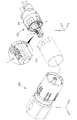
本発明の実施の形態1に係るコネクタ100は、例えば、自動車に装備される電子回路部品に用いられる無方向コネクタである。コネクタ100は、図1に示すように、雄端子を備える相手方コネクタ200に接続される。コネクタ100は、端子1と、ハウジング101と、カバー110とを備える。カバー110は、ハウジング101に組み付けられると共にハウジング101の一部を覆う。
The
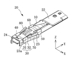
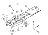
端子1は、図2(A)及び(B)に示すように、Y軸方向に延在する形状の雌端子から構成されている。本実施形態では、端子1は、一枚の金属板から形成されている。しかしながら、これに限らず、端子1は、2枚以上の金属板から形成された複数ピースタイプの端子であってもよい。端子1は、導電性接触板10と、導電性本体部20と、延出部30,40,50,60と、ランス70,80と、かしめ部90とを備える。
As shown in FIGS. 2A and 2B, the
導電性接触板10は、銅、銅合金等からなる弾性と導電性とを有する板材から形成された板バネ部材である。導電性接触板10は、+Z側に向けて突出するアーチ状に形成されたアーチ部分を有する。導電性接触板10は、導電性本体部20に覆われると共に、導電性接触板10のアーチ部分が、導電性本体部20から露出する。導電性接触板10のアーチ部分の+Z側の面は、相手側端子である雄端子に接触する。
The
導電性本体部20は、導電性接触板10を支持する部材である。導電性本体部20は、図2(B)及び図3に示すように、底板部21と、天板部22と、+X側の側壁部である側板部23(第1壁部)と、−X側の側壁部であり、側板部24(第2壁部)とからなる角筒状に形成されている。底板部21は、天板部22に対向すると共に、側板部23は、側板部24に対向する。導電性本体部20の側板部23と側板部24との間には、導電性接触板10が配置されている。導電性本体部20は、銅、銅合金等の導電性の素材から形成されている。
The conductive
導電性本体部20には、側板部23の外壁面から突出する突部23aが形成されている。突部23aは、延出部30の−Y側の端部に隣接した位置に設けられている。なお、本実施の形態1では、突部23aは、側板部23に形成され、側板部24には形成されていない。
The conductive
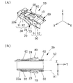
延出部30(第1延出部)は、図4(A)に示すように、導電性本体部20の+X側かつ−Y側の端部(一方の端部)に形成されている。延出部30は、折返し部分31と、重なり部分32とを有する。
As shown in FIG. 4A, the extending portion 30 (first extending portion) is formed at the + X side and −Y side end portions (one end portion) of the conductive
折返し部分31は、側板部23の上端(+Z側の端)から延出して、導電性本体部20の外方に折り返されている。詳しくは、図4(A)及び図4(B)に示すように、折返し部分31は、Y軸方向に平行な軸線A1を中心に折り返されている。
The folded
重なり部分32は、折返し部分31の先端から延出して側板部23に重なっている。この重なり部分は、側板部23に形成された突部23aに当接する。
The overlapping
延出部40(第2延出部)は、図5(A)に示すように、導電性本体部20の−X側かつ−Y側の端部に形成されている。延出部40は、延出部30と同様に、折返し部分41と、重なり部分42とを有する。
The extending part 40 (second extending part) is formed at the −X side and −Y side ends of the conductive
折返し部分41は、側板部24の上端(+Z側の端)から延出して、導電性本体部20の外方に折り返されている。詳しくは、図5(A)及び図4(B)に示すように、折返し部分41は、Y軸方向に平行な軸線A2を中心に折り返されている。
The folded
重なり部分42は、折返し部分41の先端から延出して側板部24に重なっている。
The overlapping
延出部40と延出部30とは、図2(A)に示す平面視において、導電性本体部20の軸方向に平行な軸Lに対して対称の位置に形成されている。
The
延出部50(他端側の延出部)は、図4(A)に示すように、Y軸方向において、ランス70を挟んで、延出部30の形成位置の反対側に形成されている。延出部50は、折返し部分51と、重なり部分52とを有する。
As shown in FIG. 4A, the extending portion 50 (the extending portion on the other end side) is formed on the opposite side of the forming position of the extending
折返し部分51は、側板部23の上端(+Z側の端)から延出して、導電性本体部20の外方に折り返されている。詳しくは、図4(A)及び図4(B)に示すように、折返し部分51は、Y軸方向に平行な軸線A1を中心に折り返されている。
The folded
重なり部分52は、折返し部分51の先端から延出して側板部23に重なっている。
The overlapping
延出部60は、図5(A)に示すように、Y軸方向において、ランス80を挟んで、延出部40の形成位置の反対側に形成されている。延出部60は、延出部50と同様に、折返し部分61と、重なり部分62とを有する。
As shown in FIG. 5A, the
折返し部分61は、側板部24の上端(+Z側の端)から延出して、導電性本体部20の外方に折り返されている。詳しくは、図5(A)及び図4(B)に示すように、折返し部分61は、Y軸方向に平行な軸線A2を中心に折り返されている。
The folded
重なり部分62は、折返し部分61の先端から延出して側板部24に重なっている。
The overlapping
延出部60と延出部50とは、図2(A)に示す平面視において、導電性本体部20の軸方向に平行な軸Lに対して対称の位置に形成されている。
The
また、導電性本体部20は、図5(B)に示すように、延出部30,40を含んで構成される一端側の延出部形成部分P1と、延出部50,60を含んで構成される他端側の延出部形成部分P2と、を有する。なお、図5(B)において、一端側の延出部形成部分P1及び他端側の延出部形成部分P2には、理解を容易にするためドットを付記している。一端側の延出部形成部分P1の幅W1(延出部30の外面からの延出部40の外面までの幅W1)は、他端側の延出部形成部分P2の幅W2(延出部50の外面からの延出部60の外面までの幅W2)と同一である。ただし、これに限らない。幅W2は、幅W1よりやや小さくてもよいし、幅W1よりやや大きくてもよい。
Moreover, the electroconductive main-
ランス70(第1ランス)は、ハウジングのランス掛り部に係止することで、端子1を抜止め不可能な状態で、ハウジングに保持するために形成されている。ランス70は、図4(A)に示すように、延出部30の重なり部分32から突出した状態で形成されている。これにより、ランス70は、重なり部分32側の端部を固定端とし、反対側の端部を自由端とする片持ち梁状に形成される。また、ランス70は、突出する方向に平行に形成されている折り目状の折り目部71を有する。ランス70は、折り目部71に沿って曲げられている。
The lance 70 (first lance) is formed to hold the
ランス80(第2ランス)は、ハウジングのランス掛り部に係止することで、端子1を抜止め不可能な状態で、ハウジングに保持するために形成されている。ランス80は、図5(A)に示すように、延出部40の重なり部分42から突出した状態で形成されている。これにより、ランス80は、重なり部分42側の端部を固定端とし、反対側の端部を自由端とする片持ち梁状に形成される。また、ランス80は、突出する方向に平行に形成されている折り目状の折り目部81を有する。ランス80は、折り目部81に沿って曲げられている。ランス80とランス70とは、図2(A)に示す平面視において、軸Lに対して対称に形成されている。
The lance 80 (second lance) is formed to hold the
かしめ部90は、図2(A)及び図2(B)に示すように、導体かしめ部91と被覆固定部92とを備える。導体かしめ部91は、かしめにより、絶縁被覆線の芯線の先端部に圧着され、電気的に接続される。被覆固定部92は、かしめにより、絶縁被覆線の端部を押さえて、引き抜き力から導体かしめ部91と芯線との接続を保護する。かしめ部90と導電性本体部20とが一体に形成されていることから、導体かしめ部91に圧着された芯線と導電性本体部20に接続された雄端子とが電気的に接続される。
As shown in FIGS. 2A and 2B, the
上述のように構成された端子1は、図6(A)及び図6(B)に示すように、略円筒形状に形成されたハウジング101に取り付けられる。
As shown in FIGS. 6A and 6B, the
ハウジング101は、絶縁性の素材から形成されている。ハウジング101には、端子1を収容する端子収容空間102と、ランス掛り部103,104とが形成されている。
The
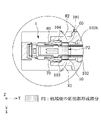
図6(A)に示すように、端子収容空間102の底面(導電性本体部20の底板部21に対向する面)には、Y軸方向に対して傾斜する傾斜面102aが形成されている。また、端子収容空間102には、図6(B)に示すように、端子収容空間102内で最も幅の狭い被嵌合空間102bが形成されている。被嵌合空間102bは、その幅W3(X軸方向における長さ)が、導電性本体部20の他端側の延出部形成部分P2の幅W2と同等である。
As shown in FIG. 6A, an
ランス掛り部103,104は、端子1のランス70、80が係止することで、端子1を抜止め不可能な状態で、ハウジング101に保持する。
The
次に、ハウジング101に端子1を取り付ける際の各部材の動作について、図6〜図8を参照して説明する。
Next, the operation of each member when attaching the
ハウジング101に端子1を取り付けるユーザは、図6(A)に示すように、ハウジング101の端子収容空間102に、+Y側の開口から端子1を挿入すると、端子1は、その導電性接触板10のアーチ部が撓みつつ、端子収容空間102内を−Y方向に移動する。また、端子1は、図6(B)に示すように、ランス70、80が矢印R1に示す方向に撓みつつ、端子収容空間102内を移動する。
When the user who attaches the
次に、端子1が端子収容空間102を移動していくと、端子1の導電性接触板10が傾斜面102aに到達する。そして、導電性接触板10は、傾斜面102aに案内されて、図7(A)に示すように、+Z側に撓み、導電性接触板10のアーチ部が+Z方向に突出する。また、端子1は、図7(B)及び図8に示すように、ランス70,80が矢印R2に示す方向に弾性回復し、ランス70,80がランス掛り部103,104に係止する。これにより、端子1は、ハウジング101から+Y方向に抜止め不可能な状態で、ハウジング101に保持される。また、導電性本体部20の他端側の延出部形成部分P2が、被嵌合空間102bに嵌る。なお、図8において、他端側の延出部形成部分P2には、理解を容易にするためドットを付記している。
Next, when the
次に、ハウジング101から端子1を取り外す方法について、図9Aを参照して説明する。
Next, a method for removing the terminal 1 from the
ハウジング101から端子1を取り外す場合、図9Aを参照するとわかるように、ユーザは、専用の治具Jを用いて、ランス70,80を矢印R1に示す方向に撓ませる。これにより、ランス70,80とランス掛り部103,104との係止が解除される。次に、端子1を+Y方向に引き抜く。以上により、ハウジング101からの端子1の取り外しが完了する。
When removing the terminal 1 from the
以上、説明したように、本実施の形態1に係る端子1によれば、図3及び図4(A)に示すように、ランス70,80は、側板部23,24に重なっている重なり部分32,42から突出する。このため、ランス70,80の形成に起因する側板部23,24の剛性の低下が抑制される。これにより、端子1の厚み(Z軸方向における寸法)を小さくすることができる。結果として、端子1の強度を維持しつつ、端子1の低背化を実現することが可能になる。
As described above, according to the
また、本実施の形態1では、導電性本体部20には、側板部23の外壁面から突出すると共に、重なり部分32に当接する突部23aが形成されている。この突部23aは、ハウジング101から端子1を引き抜く方向の力が加えられた際の、側板部23に対する重なり部分32の変形を規制するストッパーとして機能する。
In the first embodiment, the conductive
例えば、導電性本体部20に突部23aが形成されていない例について説明する。ハウジング101から端子1を取り外す通常の動作とは異なる動作が働いた場合、ランス70,80がランス掛り部103,104に係止されているので、導電性本体部20に通常の引抜き力とは異なる予期せぬ力Fが加わることがある。この場合、図9Aの矢印A3に示す方向(−Y方向)に、側板部23に対して、重なり部分32が変形するおそれがある。これに対して、本実施の形態1では、図3及び図4(A)に示すように、突部23aがストッパーとして機能するため、導電性本体部20に予期せぬ力Fが加えられた際の、側板部23に対する重なり部分32の変形を抑制することができる。
For example, an example in which the
また、本実施の形態1に係る端子1は、図8に示すように、延出部50,60を備えている。これら延出部50,60を含んで構成された他端側の延出部形成部分P2のX軸方向における幅W2は、ハウジング101の端子収容空間102の被嵌合空間102bのX軸方向における幅W3と同等である(図6(B)参照)。このため、端子1が端子収容空間102に収容されると、他端側の延出部形成部分P2が被嵌合空間102bに嵌合することにより、端子収容空間102に収納された端子1のがたつきを抑制することができる。また、端子収容空間102内で端子1が−X方向又は+X方向に片寄ることにより、ランス70,80とランス掛り部103,104との係止が外れることを抑制することができる。なお、幅W2が、幅W3よりもわずかに大きかったり、わずかに小さかったりしていても、同様の効果を奏することができる。
Further, the
また、本実施の形態1に係る端子1においては、図4(A)に示すように、ランス70,80は、その突出する方向に平行に形成されている折り目部71,81を有する。この折り目部71,81により、ランス70,80の強度を向上させることができる。また、導電性本体部20に通常の引抜き力とは異なる予期せぬ力Fが加えられた際に、ランス70,80の自由端の戻りを抑制することができる。例えば、ランス70,80が折り目部71,81を有していない図9Bに示す例の場合、導電性本体部20に予期せぬ力Fが加えられると、ランス70の自由端が−Y方向に戻り、ランス70に戻り部分72が形成されるおそれがある。しかしながら、本実施の形態1では、ランス70,80が、折り目部71,81を有していることから、ランス70,80の自由端の戻りを抑制でき、結果として、ハウジング101に対する端子1の保持力を向上させることができる。
Further, in the
実施の形態2.
以下、本発明の実施の形態2に係る端子を、図10A、図10Bを参照して説明する。実施の形態1との相違点を主に説明する。説明した相違点以外は、実施の形態1と同じものとする。なお、理解を容易にするために、XYZ座標を設定し、適宜参照する。
Hereinafter, the terminal according to
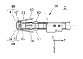
本発明の実施の形態2に係る端子2は、図10A及び図10Bに示すように、導電性接触板10と、導電性本体部20と、延出部30,40,50,60と、ランス70,80と、かしめ部(図示せず)とを備える。実施の形態2に係る端子2では、延出部30,40の折返し部分31,41の折返し形状が異なる点で、実施の形態1に係る端子1と相違する。
As shown in FIGS. 10A and 10B, the
延出部30(第1延出部)は、導電性本体部20の+X側かつ−Y側の端部(一方の端部)に形成されている。延出部30は、折返し部分31と、重なり部分32とを有する。
The extending portion 30 (first extending portion) is formed at the + X side and −Y side end portions (one end portion) of the conductive
折返し部分31は、側板部23の先端(−Y側の端)から延出して、導電性本体部20の外方に折り返されている。詳しくは、折返し部分31は、Y軸方向に直交する方向に平行な軸線(Z軸方向に平行な軸線)を中心に折り返されている。
The folded
重なり部分32は、折返し部分31の先端から延出して側板部23に重なっている。
The overlapping
延出部40(第2延出部)は、導電性本体部20の−X側かつ−Y側の端部(一方の端部)に形成されている。延出部40は、延出部30と同様に、折返し部分41と、重なり部分42とを有する。
The extension part 40 (second extension part) is formed on the −X side and −Y side end parts (one end part) of the conductive
折返し部分41は、側板部24の先端(−Y側の端)から延出して、導電性本体部20の外方に折り返されている。詳しくは、折返し部分41は、Y軸方向に直交する方向に平行な軸線(Z軸方向に平行な軸線)を中心に折り返されている。
The folded
重なり部分42は、折返し部分41の先端から延出して側板部24に重なっている。
The overlapping
延出部40と延出部30とは、図10Bに示す平面視において、導電性本体部20の軸方向に平行な軸に対して対称の位置に形成されている。
The
以上、説明したように、本実施の形態2に係る端子2によれば、ランス70,80は、側板部23,24に重なっている重なり部分32,42から突出する。このため、ランス70,80の形成に起因する側板部23,24の剛性の低下が抑制される。これにより、端子2の厚み(Z軸方向における寸法)を小さくすることができる。結果として、端子2の強度を維持しつつ、端子2の低背化を実現することが可能になる。また、実施の形態1に係る端子1と同様の効果を奏することができる。
As described above, according to the
実施の形態3.
以下、本発明の実施の形態3に係る端子を、図11A、図11Bを参照して説明する。実施の形態2との相違点を主に説明する。説明した相違点以外は、実施の形態2と同じものとする。なお、理解を容易にするために、XYZ座標を設定し、適宜参照する。
Hereinafter, the terminal according to
本発明の実施の形態3に係る端子3は、図11A及び図11Bに示すように、導電性接触板10と、導電性本体部20と、延出部30と、ランス70と、かしめ部(図示せず)とを備える。実施の形態3に係る端子3では、延出部30の形成数,ランスの形成数が異なる点で、実施の形態2に係る端子2と相違する。
As shown in FIGS. 11A and 11B, the
延出部30(第1延出部)は、導電性本体部20の−Z側かつ−Y側の端部(一方の端部)に形成されている。延出部30は、折返し部分31と、重なり部分32とを有する。
The extension part 30 (first extension part) is formed at the end part (one end part) on the −Z side and the −Y side of the conductive
折返し部分31は、底板部21(第1壁部)の先端(−Y側の端)から延出して、導電性本体部20の外方に折り返されている。詳しくは、折返し部分31は、Y軸方向に直交する方向に平行な軸線(X軸方向に平行な軸線)を中心に折り返されている。
The folded
重なり部分32は、折返し部分31の先端から延出して底板部21に重なっている。
The overlapping
ランス70(第1ランス)は、ハウジングのランス掛り部に係止することで、端子3を抜止め不可能な状態で、ハウジングに保持するために形成されている。ランス70は、延出部30の重なり部分32から突出した状態で形成されている。これにより、ランス70は、重なり部分32側の端部を固定端とし、反対側の端部を自由端とする片持ち梁状に形成される。また、ランス70は、突出する方向に平行に形成されている折り目状の折り目部を有する。
The lance 70 (first lance) is formed to hold the
なお、本発明は、上記実施の形態に限定されず、本発明の要旨を逸脱しない範囲での種々の変更が可能である。 In addition, this invention is not limited to the said embodiment, A various change in the range which does not deviate from the summary of this invention is possible.
例えば、本実施の形態1においては、突部23aは、側板部23に形成され、側板部24には形成されていない。しかしながら、これに限られない。突部23aは、側板部23及び側板部24の両方に形成されていてもよい。
For example, in the first embodiment, the protruding
本発明は、本発明の広義の精神と範囲を逸脱することなく、様々な実施の形態及び変形が可能とされるものである。また、上述した実施の形態は、この発明を説明するためのものであり、本発明の範囲を限定するものではない。すなわち、本発明の範囲は、実施の形態ではなく、特許請求の範囲によって示される。そして、特許請求の範囲内及びそれと同等の発明の意義の範囲内で施される様々な変形が、この発明の範囲内とみなされる。 Various embodiments and modifications can be made to the present invention without departing from the broad spirit and scope of the present invention. The above-described embodiments are for explaining the present invention and do not limit the scope of the present invention. In other words, the scope of the present invention is shown not by the embodiments but by the claims. Various modifications within the scope of the claims and within the scope of the equivalent invention are considered to be within the scope of the present invention.
1,2,3:端子、10:導電性接触板、20:導電性本体部、21:底板部、22:天板部、23:側板部(第1壁部)、23a:突部、24:側板部(第2壁部)、30:延出部(第1延出部)、31:折返し部分(第1の折返し部分)、32:重なり部分(第1の重なり部分)、40:延出部(第2延出部)、41:折返し部分(第2の折返し部分)、42:重なり部分(第2の重なり部分)、50:延出部(他端側の延出部)、51:折返し部分(他端側の折返し部分)、52:重なり部分(他端側の重なり部分)、60:延出部、61:折返し部分、62:重なり部分、70:ランス(第1ランス)、71:折り目部、72:戻り部分、80:ランス(第2ランス)、81:折り目部、90:かしめ部、91:導体かしめ部、92:被覆固定部、100:コネクタ、101:ハウジング、102:端子収容空間、102a:傾斜面、102b:被嵌合空間、103,104:ランス掛り部、110:カバー、200:相手方コネクタ、A1,A2:軸線、J:治具、L:軸、R1,R2:矢印、W1,W2,W3:幅、P1:一端側の延出部形成部分、P2:他端側の延出部形成部分 1, 2, 3: Terminals, 10: Conductive contact plate, 20: Conductive main body, 21: Bottom plate, 22: Top plate, 23: Side plate (first wall), 23a: Projection, 24 : Side plate part (second wall part), 30: extension part (first extension part), 31: folded part (first folded part), 32: overlapping part (first overlapping part), 40: extended Protruding part (second extending part), 41: folded part (second folded part), 42: overlapping part (second overlapping part), 50: extending part (extending part on the other end side), 51 : Folded portion (folded portion on the other end side), 52: overlapped portion (overlapped portion on the other end side), 60: extended portion, 61: folded portion, 62: overlapped portion, 70: lance (first lance), 71: crease part, 72: return part, 80: lance (second lance), 81: crease part, 90: caulking part, 91: conductor caulking part, 92 Cover fixing portion, 100: connector, 101: housing, 102: terminal accommodating space, 102a: inclined surface, 102b: mated space, 103, 104: lance hanging portion, 110: cover, 200: mating connector, A1, A2 : Axis, J: jig, L: shaft, R1, R2: arrows, W1, W2, W3: width, P1: extended portion forming portion on one end side, P2: extended portion forming portion on the other end side
Claims (10)
前記導電性接触板を支持し、第1壁部を有する筒状の導電性本体部と、
前記第1壁部の端から延出して前記導電性本体部の外方に折り返されている第1の折返し部分と、前記第1の折返し部分の先端から延出して前記第1壁部に重なっている第1の重なり部分と、を有する第1延出部と、
前記第1の重なり部分から突出する片持ち梁状の第1ランスと、
を備える、端子。 A conductive contact plate that has elasticity and contacts the mating terminal;
A cylindrical conductive main body portion supporting the conductive contact plate and having a first wall portion;
A first folded portion that extends from an end of the first wall portion and is folded outward from the conductive main body portion, and extends from a tip of the first folded portion and overlaps the first wall portion. A first extending portion having a first overlapping portion,
A cantilever-shaped first lance projecting from the first overlapping portion;
Comprising a terminal.
前記導電性接触板は、前記第1壁部と前記第2壁部との間に配置されている、請求項1に記載の端子。 The conductive body portion has a second wall portion facing the first wall portion,
The terminal according to claim 1, wherein the conductive contact plate is disposed between the first wall portion and the second wall portion.
前記第2の重なり部分から突出する片持ち梁状の第2ランスと、
を備える請求項2に記載の端子。 A second folded portion extending from an end of the second wall portion and folded outward from the conductive body portion; and a second folded portion extending from a tip of the second folded portion and overlapping the second wall portion. A second overlapping portion having a second overlapping portion,
A second lance in the form of a cantilever projecting from the second overlapping portion;
The terminal according to claim 2, comprising:
前記第1の折返し部分は、前記導電性本体部の軸方向に直交する方向に平行な軸線を中心に折り返されている、請求項1に記載の端子。 The first wall portion faces the conductive contact plate,
The terminal according to claim 1, wherein the first folded portion is folded around an axis parallel to a direction orthogonal to the axial direction of the conductive main body.
前記第1ランスを挟んだ、前記導電性本体部の他方の端部側に形成されている他端側の延出部を備え、
前記他端側の延出部は、前記第1壁部の端から延出して、前記導電性本体部の外方に折り返されている他端側の折返し部分と、前記他端側の折返し部分の先端から延出して前記第1壁部に重なっている他端側の重なり部分と、を有する、請求項1から8のいずれか一項に記載の端子。 The first extension part is formed at one end of the conductive main body part,
An extension portion on the other end side formed on the other end portion side of the conductive main body portion with the first lance interposed therebetween,
The extension portion on the other end side extends from the end of the first wall portion, and is folded back to the outside of the conductive main body portion, and the folded portion on the other end side. The terminal according to claim 1, further comprising an overlapping portion on the other end side that extends from the tip of the first electrode and overlaps the first wall portion.
前記第1ランスに係合する係合部が形成されているハウジングと、
を備える、コネクタ。 The terminal according to any one of claims 1 to 9,
A housing in which an engaging portion that engages with the first lance is formed;
Comprising a connector.
Priority Applications (5)
| Application Number | Priority Date | Filing Date | Title |
|---|---|---|---|
| JP2016089095A JP6341225B2 (en) | 2016-04-27 | 2016-04-27 | Terminals and connectors |
| US15/489,365 US9905955B2 (en) | 2016-04-27 | 2017-04-17 | Terminal and connector |
| EP17167901.2A EP3240115B1 (en) | 2016-04-27 | 2017-04-25 | Terminal and connector |
| KR1020170053623A KR101911174B1 (en) | 2016-04-27 | 2017-04-26 | Terminal and connector |
| CN201710287708.3A CN107425329B (en) | 2016-04-27 | 2017-04-27 | Terminal and connector |
Applications Claiming Priority (1)
| Application Number | Priority Date | Filing Date | Title |
|---|---|---|---|
| JP2016089095A JP6341225B2 (en) | 2016-04-27 | 2016-04-27 | Terminals and connectors |
Publications (2)
| Publication Number | Publication Date |
|---|---|
| JP2017199541A true JP2017199541A (en) | 2017-11-02 |
| JP6341225B2 JP6341225B2 (en) | 2018-06-13 |
Family
ID=58632268
Family Applications (1)
| Application Number | Title | Priority Date | Filing Date |
|---|---|---|---|
| JP2016089095A Expired - Fee Related JP6341225B2 (en) | 2016-04-27 | 2016-04-27 | Terminals and connectors |
Country Status (5)
| Country | Link |
|---|---|
| US (1) | US9905955B2 (en) |
| EP (1) | EP3240115B1 (en) |
| JP (1) | JP6341225B2 (en) |
| KR (1) | KR101911174B1 (en) |
| CN (1) | CN107425329B (en) |
Families Citing this family (8)
| Publication number | Priority date | Publication date | Assignee | Title |
|---|---|---|---|---|
| US9905953B1 (en) | 2016-09-30 | 2018-02-27 | Slobodan Pavlovic | High power spring-actuated electrical connector |
| DE102018106646A1 (en) * | 2017-03-22 | 2018-09-27 | Hirschmann Automotive Gmbh | Contact element for a connector |
| CN107968268A (en) * | 2018-01-04 | 2018-04-27 | 镇江市丹徒区飞翔电子有限公司 | A kind of electronic connector |
| MX2020008873A (en) | 2018-02-26 | 2021-01-08 | Royal Prec Products Llc | Spring-actuated electrical connector for high-power applications. |
| DE112019002878T5 (en) | 2018-06-07 | 2021-05-06 | Royal Precision Products, Llc | ELECTRICAL CONNECTOR ARRANGEMENT WITH INTERNAL SPRING COMPONENT |
| DE112020003846T5 (en) | 2019-09-09 | 2022-05-12 | Royal Precision Products Llc | CONNECTOR RECORDING SYSTEM WITH READABLE AND RECORDABLE MARKERS |
| US11721942B2 (en) | 2019-09-09 | 2023-08-08 | Eaton Intelligent Power Limited | Connector system for a component in a power management system in a motor vehicle |
| DE112021003303T5 (en) | 2020-07-29 | 2023-05-25 | Eaton Intelligent Power Limited | ELECTRICAL CONNECTION SYSTEM WITH CYLINDRICAL CLAMP BODY |
Citations (7)
| Publication number | Priority date | Publication date | Assignee | Title |
|---|---|---|---|---|
| US3058091A (en) * | 1959-06-04 | 1962-10-09 | Amp Inc | Sheet metal pin socket |
| US4713026A (en) * | 1986-10-08 | 1987-12-15 | Interlock Corporation | Tab receptacle terminal having improved electrical and mechanical features |
| US4781628A (en) * | 1987-10-22 | 1988-11-01 | General Motors Corporation | Female electrical terminal |
| JPH06310218A (en) * | 1993-04-28 | 1994-11-04 | Yazaki Corp | Shield connector terminal, and shield connector |
| JP2002124335A (en) * | 2000-10-18 | 2002-04-26 | Sumitomo Wiring Syst Ltd | Terminal fitting |
| JP2004039534A (en) * | 2002-07-05 | 2004-02-05 | Sumitomo Wiring Syst Ltd | Connector |
| WO2014045957A1 (en) * | 2012-09-21 | 2014-03-27 | 矢崎総業株式会社 | Connector |
Family Cites Families (20)
| Publication number | Priority date | Publication date | Assignee | Title |
|---|---|---|---|---|
| US4209220A (en) * | 1978-06-05 | 1980-06-24 | General Motors Corporation | Wipe-in terminal for printed circuits |
| GB9301541D0 (en) * | 1993-01-27 | 1993-03-17 | Amp Gmbh | An electrical terminal with means to avoid locking lance damage and entanglement |
| JP3319292B2 (en) * | 1996-07-26 | 2002-08-26 | 住友電装株式会社 | Female terminal fitting |
| JP3225863B2 (en) * | 1996-12-03 | 2001-11-05 | 住友電装株式会社 | Terminal fitting |
| JPH10247543A (en) | 1997-03-03 | 1998-09-14 | Sumitomo Wiring Syst Ltd | Terminal |
| JP3494857B2 (en) * | 1997-08-08 | 2004-02-09 | 矢崎総業株式会社 | Connecting terminal |
| JP3656547B2 (en) * | 2000-12-21 | 2005-06-08 | 住友電装株式会社 | Terminal bracket |
| JP3745634B2 (en) | 2001-03-15 | 2006-02-15 | 矢崎総業株式会社 | Terminal fitting |
| JP4099219B2 (en) * | 2003-04-15 | 2008-06-11 | 日本圧着端子製造株式会社 | Terminal |
| US6905376B2 (en) * | 2003-04-15 | 2005-06-14 | J.S.T. Mfg. Co., Ltd. | Terminal |
| JP4013151B2 (en) * | 2004-04-13 | 2007-11-28 | 住友電装株式会社 | Female terminal bracket |
| US7175487B2 (en) | 2004-06-28 | 2007-02-13 | Delphi Technologies, Inc. | Electrical terminal element |
| US7537497B2 (en) * | 2005-09-26 | 2009-05-26 | Fci Americas Technology, Inc. | Multi-piece electrical receptacle terminal |
| US7371133B1 (en) * | 2007-01-18 | 2008-05-13 | Delphi Technologies, Inc. | Electrical socket terminal having a contact stabilizer |
| DE102007040937B3 (en) * | 2007-08-30 | 2009-01-15 | Tyco Electronics Amp Gmbh | Electric contact |
| JP4651129B2 (en) * | 2008-12-26 | 2011-03-16 | 日本航空電子工業株式会社 | Socket contacts and connectors |
| DE102012209423A1 (en) | 2012-06-04 | 2013-12-05 | Robert Bosch Gmbh | Contact with a resistant primary lance for locking in a contact chamber of a connector |
| EP2690716B1 (en) * | 2012-07-24 | 2018-05-02 | Delphi Technologies, Inc. | Electrical connecting element |
| EP2797173B8 (en) * | 2013-04-26 | 2019-01-09 | Aptiv Technologies Limited | Electrical terminal with a locking lance and manufacturing process thereof |
| DE102013223570B4 (en) * | 2013-11-19 | 2021-06-24 | Te Connectivity Germany Gmbh | Pin contact with a contact body manufactured as a stamped and bent part and a solid contact pin |
-
2016
- 2016-04-27 JP JP2016089095A patent/JP6341225B2/en not_active Expired - Fee Related
-
2017
- 2017-04-17 US US15/489,365 patent/US9905955B2/en not_active Expired - Fee Related
- 2017-04-25 EP EP17167901.2A patent/EP3240115B1/en not_active Not-in-force
- 2017-04-26 KR KR1020170053623A patent/KR101911174B1/en active IP Right Grant
- 2017-04-27 CN CN201710287708.3A patent/CN107425329B/en not_active Expired - Fee Related
Patent Citations (7)
| Publication number | Priority date | Publication date | Assignee | Title |
|---|---|---|---|---|
| US3058091A (en) * | 1959-06-04 | 1962-10-09 | Amp Inc | Sheet metal pin socket |
| US4713026A (en) * | 1986-10-08 | 1987-12-15 | Interlock Corporation | Tab receptacle terminal having improved electrical and mechanical features |
| US4781628A (en) * | 1987-10-22 | 1988-11-01 | General Motors Corporation | Female electrical terminal |
| JPH06310218A (en) * | 1993-04-28 | 1994-11-04 | Yazaki Corp | Shield connector terminal, and shield connector |
| JP2002124335A (en) * | 2000-10-18 | 2002-04-26 | Sumitomo Wiring Syst Ltd | Terminal fitting |
| JP2004039534A (en) * | 2002-07-05 | 2004-02-05 | Sumitomo Wiring Syst Ltd | Connector |
| WO2014045957A1 (en) * | 2012-09-21 | 2014-03-27 | 矢崎総業株式会社 | Connector |
Also Published As
| Publication number | Publication date |
|---|---|
| EP3240115A1 (en) | 2017-11-01 |
| CN107425329B (en) | 2019-05-28 |
| EP3240115B1 (en) | 2019-01-09 |
| KR101911174B1 (en) | 2018-12-19 |
| CN107425329A (en) | 2017-12-01 |
| JP6341225B2 (en) | 2018-06-13 |
| US20170317441A1 (en) | 2017-11-02 |
| KR20170122672A (en) | 2017-11-06 |
| US9905955B2 (en) | 2018-02-27 |
Similar Documents
| Publication | Publication Date | Title |
|---|---|---|
| JP6341225B2 (en) | Terminals and connectors | |
| EP2690713B1 (en) | Wire-to-board connector | |
| JP5956071B2 (en) | Connecting terminal | |
| JPH11345645A (en) | Receptacle electric terminal | |
| TWI559626B (en) | Receptacle connector that can easily obtain a desired friction lock without forming a large opening in a metal shell | |
| JP2009026667A (en) | Electric connector | |
| US10741974B2 (en) | Electrical connector | |
| JP2016189273A (en) | Connector and electrical connection device | |
| CN103081249B (en) | The mistake of connector is inserted and is prevented structure | |
| JP4482568B2 (en) | Electrical connector | |
| JP6486309B2 (en) | connector | |
| US11018445B2 (en) | Terminal with electrically conductive tubular shaped body portion | |
| JP5201253B2 (en) | Connector terminal | |
| JP2010157367A (en) | Electrical connector | |
| KR101237222B1 (en) | Shield case for receptacle | |
| JP5711568B2 (en) | Butting terminal | |
| JP5650487B2 (en) | connector | |
| JP7261044B2 (en) | male terminal | |
| JP6076953B2 (en) | Board terminal | |
| JP4551276B2 (en) | Plug with locking mechanism | |
| JP7466116B2 (en) | Connector set and connector | |
| JP7215933B2 (en) | Connecting terminal | |
| JP7139062B2 (en) | Terminal connection structure | |
| JP6451714B2 (en) | Connector, connector unit, and connector manufacturing method | |
| JP2022063490A (en) | Terminal |
Legal Events
| Date | Code | Title | Description |
|---|---|---|---|
| A977 | Report on retrieval |
Free format text: JAPANESE INTERMEDIATE CODE: A971007 Effective date: 20171027 |
|
| A131 | Notification of reasons for refusal |
Free format text: JAPANESE INTERMEDIATE CODE: A131 Effective date: 20171107 |
|
| A521 | Request for written amendment filed |
Free format text: JAPANESE INTERMEDIATE CODE: A523 Effective date: 20180104 |
|
| TRDD | Decision of grant or rejection written | ||
| A01 | Written decision to grant a patent or to grant a registration (utility model) |
Free format text: JAPANESE INTERMEDIATE CODE: A01 Effective date: 20180417 |
|
| A61 | First payment of annual fees (during grant procedure) |
Free format text: JAPANESE INTERMEDIATE CODE: A61 Effective date: 20180430 |
|
| R150 | Certificate of patent or registration of utility model |
Ref document number: 6341225 Country of ref document: JP Free format text: JAPANESE INTERMEDIATE CODE: R150 |
|
| R250 | Receipt of annual fees |
Free format text: JAPANESE INTERMEDIATE CODE: R250 |
|
| R250 | Receipt of annual fees |
Free format text: JAPANESE INTERMEDIATE CODE: R250 |
|
| LAPS | Cancellation because of no payment of annual fees |