JP2017191092A - Rotation detector and electrically-driven power steering device using the rotation detector - Google Patents
Rotation detector and electrically-driven power steering device using the rotation detector Download PDFInfo
- Publication number
- JP2017191092A JP2017191092A JP2017023440A JP2017023440A JP2017191092A JP 2017191092 A JP2017191092 A JP 2017191092A JP 2017023440 A JP2017023440 A JP 2017023440A JP 2017023440 A JP2017023440 A JP 2017023440A JP 2017191092 A JP2017191092 A JP 2017191092A
- Authority
- JP
- Japan
- Prior art keywords
- rotation
- unit
- sensor
- signal
- rotation angle
- Prior art date
- Legal status (The legal status is an assumption and is not a legal conclusion. Google has not performed a legal analysis and makes no representation as to the accuracy of the status listed.)
- Granted
Links
Images


Classifications
-
- B—PERFORMING OPERATIONS; TRANSPORTING
- B62—LAND VEHICLES FOR TRAVELLING OTHERWISE THAN ON RAILS
- B62D—MOTOR VEHICLES; TRAILERS
- B62D5/00—Power-assisted or power-driven steering
- B62D5/04—Power-assisted or power-driven steering electrical, e.g. using an electric servo-motor connected to, or forming part of, the steering gear
-
- G—PHYSICS
- G01—MEASURING; TESTING
- G01B—MEASURING LENGTH, THICKNESS OR SIMILAR LINEAR DIMENSIONS; MEASURING ANGLES; MEASURING AREAS; MEASURING IRREGULARITIES OF SURFACES OR CONTOURS
- G01B7/00—Measuring arrangements characterised by the use of electric or magnetic techniques
- G01B7/30—Measuring arrangements characterised by the use of electric or magnetic techniques for measuring angles or tapers; for testing the alignment of axes
Abstract
Description
本発明は、回転検出装置、および、これを用いた電動パワーステアリング装置に関する。 The present invention relates to a rotation detection device and an electric power steering device using the rotation detection device.
従来、磁気検出素子の検出値に基づき、モータの回転角情報を生成する装置が知られている。例えば特許文献1の電動パワーステアリング用電子制御ユニットでは、第1の磁気検出素子から出力される信号、および、第2の磁気検出素子から出力される信号に基づき、電動モータの回転角情報を生成し、生成した回転角情報からステアリングの位置を算出している。
2. Description of the Related Art Conventionally, devices that generate rotation angle information of a motor based on a detection value of a magnetic detection element are known. For example, in the electric power steering electronic control unit of
特許文献1では、2つの磁気検出素子の情報を、別々に制御回路部に出力している。そのため、検出タイミングや信号出力のタイミングのずれにより、回転角情報から算出されたステアリングの位置が実際のステアリング位置とずれる虞がある。
本発明は、上述の課題に鑑みてなされたものであり、その目的は、制御部に送信される回転角信号および回転回数信号に係る検出値の検出タイミングのずれを低減可能な回転検出装置、および、これを用いた電動パワーステアリング装置を提供することにある。
In
The present invention has been made in view of the above-described problems, and an object of the present invention is to provide a rotation detection device capable of reducing a shift in detection timing of detection values related to a rotation angle signal and a rotation frequency signal transmitted to a control unit, Another object of the present invention is to provide an electric power steering apparatus using the same.
本発明の回転検出装置は、センサ部(61、62、261、262、361、362、461、462、561、562)と、制御部(51、52、53)と、を備える。
センサ部は、センサ素子(601〜608)、および、回路部(610〜612、620〜623)を有する。
センサ素子は、検出対象(10)の回転を検出する。回路部は、センサ素子の検出値に基づく出力信号を生成して出力する。
制御部は、センサ部からの出力信号を取得し、出力信号に基づく演算を行う。
回路部は、回転角演算部(614、624、616、626)、回転回数演算部(615、625、617、627)、および、通信部(619、629)を有する。回転角演算部は、センサ素子の検出値に基づいて、検出対象の回転角を演算する。回転回数演算部は、センサ素子の検出値に基づいて、検出対象の回転回数をカウントする。通信部は、回転角に係る信号である回転角信号、および、回転回数に係る信号である回転回数信号を含む一連の信号である出力信号を制御部に送信する。
The rotation detection device of the present invention includes a sensor unit (61, 62, 261, 262, 361, 362, 461, 462, 561, 562) and a control unit (51, 52, 53).
The sensor unit includes sensor elements (601 to 608) and circuit units (610 to 612, 620 to 623).
The sensor element detects the rotation of the detection target (10). The circuit unit generates and outputs an output signal based on the detection value of the sensor element.
A control part acquires the output signal from a sensor part, and performs the calculation based on an output signal.
The circuit unit includes a rotation angle calculation unit (614, 624, 616, 626), a rotation number calculation unit (615, 625, 617, 627), and a communication unit (619, 629). The rotation angle calculation unit calculates a rotation angle to be detected based on the detection value of the sensor element. The rotation number calculation unit counts the number of rotations to be detected based on the detection value of the sensor element. The communication unit transmits an output signal, which is a series of signals including a rotation angle signal that is a signal related to the rotation angle and a rotation frequency signal that is a signal related to the rotation frequency, to the control unit.
本発明では、回転角信号および回転回数信号は、一連の出力信号に含まれ、通信部から制御部に送信されるので、回転角信号および回転回数信号を、1回の通信で制御部に送信可能である。これにより、回転角信号および回転回数信号に係る検出値の検出タイミングのずれを低減することができる。 In the present invention, the rotation angle signal and the rotation frequency signal are included in a series of output signals and are transmitted from the communication unit to the control unit. Therefore, the rotation angle signal and the rotation frequency signal are transmitted to the control unit in one communication. Is possible. Thereby, the shift | offset | difference of the detection timing of the detected value concerning a rotation angle signal and a rotation frequency signal can be reduced.
以下、本発明による回転検出装置、および、これを用いた電動パワーステアリング装置を図面に基づいて説明する。以下、複数の実施形態において、実質的に同一の構成には同一の符号を付して説明を省略する。
(第1実施形態)
本発明の第1実施形態を図1〜図11に示す。
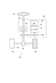
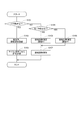
図1に示すように、回転検出装置1は、運転者によるステアリング操作を補助するための電動パワーステアリング装置108の駆動装置800に設けられる。駆動装置800は、モータ部10と、モータ部10の駆動制御に係るコントローラ部20とが一体に形成される。図1では、コントローラ部20を「ECU」と記載した。
Hereinafter, a rotation detection device according to the present invention and an electric power steering device using the rotation detection device will be described with reference to the drawings. Hereinafter, in a plurality of embodiments, the same numerals are given to the substantially same composition, and explanation is omitted.
(First embodiment)
A first embodiment of the present invention is shown in FIGS.
As shown in FIG. 1, the
図1は、電動パワーステアリング装置108を備えるステアリングシステム100の全体構成を示すものである。ステアリングシステム100は、操舵部材としてのステアリングホイール101、ステアリングシャフト102、ピニオンギア104、ラック軸105、車輪106、および、電動パワーステアリング装置108等から構成される。
FIG. 1 shows an overall configuration of a
ステアリングホイール101は、ステアリングシャフト102と接続される。ステアリングシャフト102には、操舵トルクを検出するトルクセンサ103が設けられる。トルクセンサ103は、図示しないトーションバーを有している。トーションバーは、ステアリングシャフト102の上側と下側とを同軸に接続している。ここでは、ステアリングホイール101側を上側、ピニオンギア104側を下側とする。
ステアリングシャフト102の先端には、ピニオンギア104が設けられ、ピニオンギア104はラック軸105に噛み合っている。ラック軸105の両端には、タイロッド等を介して一対の車輪106が設けられる。
The
A
運転者がステアリングホイール101を回転させると、ステアリングホイール101に接続されたステアリングシャフト102が回転する。ステアリングシャフト102の回転運動は、ピニオンギア104によりラック軸105の直線運動に変換され、ラック軸105の変位量に応じた角度に一対の車輪106が操舵される。
When the driver rotates the
電動パワーステアリング装置108は、駆動装置800、動力伝達部としての減速ギア109、および、トルクセンサ103等を備える。電動パワーステアリング装置108は、トルクセンサ103から取得される操舵トルクや、図示しないCAN(Controller Area Network)から取得される車速等の信号に基づき、ステアリングホイール101の操舵を補助するための補助トルクをモータ部10から出力し、減速ギア109を介してステアリングシャフト102に伝達する。すなわち、本実施形態の電動パワーステアリング装置108は、モータ部10にて発生したトルクにてステアリングシャフト102の回転をアシストする、所謂「コラムアシスト」であるが、ラック軸105の駆動をアシストする、所謂「ラックアシスト」としてもよい。換言すると、本実施形態では、ステアリングシャフト102が駆動対象であるが、ラック軸105を駆動対象としてもよい、ということである。
The electric
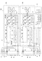
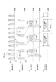
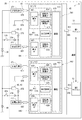
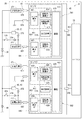
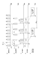
次に、電動パワーステアリング装置108の電気的構成を図2に基づいて説明する。なお、図2においては、基板21、22における基板配線を細線で記載するとともに、煩雑になることを避けるため、一部の配線等を省略している。
モータ部10は、三相ブラシレスモータであって、図示しないステータに巻回される2組の巻線組11、12を有する。第1巻線組11は、U1コイル111、V1コイル112、および、W1コイル113を有する。第2巻線組12は、U2コイル121、V2コイル122、および、W2コイル123を有する。ここで、第1巻線組11の各相に流れる電流を、相電流Iu1、Iv1、Iw1、第2巻線組12の各相に流れる電流を、相電流Iu2、Iv2、Iw2とする。
Next, the electrical configuration of the electric
The
第1巻線組11には、第1インバータ30が接続され、第1インバータ30を経由して、第1バッテリ39から電力が供給される。
第1インバータ30は、第1巻線組11の電力を変換するものであって、6つのスイッチング素子301〜306がブリッジ接続されている。以下、「スイッチング素子」を「SW素子」と記す。本実施形態のSW素子301〜306は、MOSFETであるが、IGBTやサイリスタ等としてもよい。後述のSW素子401〜406、および、リレー32、33、42、43等も同様である。
A
The
SW素子301〜303が高電位側に配置され、SW素子304〜306が低電位側に配置される。対になるU相のSW素子301、304の接続点には、U1コイル111の一端が接続される。対になるV相のSW素子302、305の接続点には、V1コイル112の一端が接続される。対になるW相のSW素子303、306の接続点には、W1コイル113の一端が接続される。
SW素子304〜306の低電位側には、相電流Iu1、Iv1、Iw1を検出するための第1電流センサ31が設けられる。第1電流センサ31は、各相に設けられる電流検出素子311〜313を有する。本実施形態の電流検出素子311〜313は、シャント抵抗であるが、ホール素子等としてもよい。後述の電流検出素子411〜413も同様である。
A first
第1電源リレー32は、第1バッテリ39と第1インバータ30との間に設けられ、第1バッテリ39と第1インバータ30との間における電流を導通または遮断する。
第1逆接保護リレー33は、第1電源リレー32と第1インバータ30との間に設けられる。第1逆接保護リレー33は、寄生ダイオードの向きが第1電源リレー32と逆向きとなるように接続される。これにより、第1バッテリ39が逆向きに接続された場合に逆向きの電流が流れるのを防ぐ。
The first
The first reverse
第1チョークコイル35は、第1電源リレー32の第1バッテリ39側に設けられる。第1コンデンサ36は、第1インバータ30と並列に接続される。チョークコイル35およびコンデンサ36は、フィルタ回路を構成し、バッテリ39を共有する他の装置から伝わるノイズを低減するとともに、駆動装置800からバッテリ39を共有する他の装置に伝わるノイズを低減する。また、コンデンサ36は、電荷を蓄えることで、第1インバータ30への電力供給を補助する。
The
第2巻線組12には、第2インバータ40が接続され、第2インバータ40を経由して、第2バッテリ49から電力が供給される。
第2インバータ40は、第2巻線組12の電力を変換するものであって、6つのSW素子401〜406がブリッジ接続されている。
SW素子401〜403が高電位側に配置され、SW素子404〜406が低電位側に配置される。対になるU相のSW素子401、404の接続点には、U2コイル121の一端が接続される。対になるV相のSW素子402、405の接続点には、V2コイル122の一端が接続される。対になるW相のSW素子403、406の接続点には、W2コイル123の一端が接続される。
SW素子404〜406の低電位側には、第2電流センサ41が設けられる。第2電流センサ41は、各相に設けられる電流検出素子411〜413を有する。
A
The
A second
第2バッテリ49と第2インバータ40との間には、第2バッテリ49側から、第2チョークコイル45、第2電源リレー42、第2逆接保護リレー43が設けられる。また、第2コンデンサ46は、第2インバータ40と並列に接続される。
第2電源リレー42、第2逆接保護リレー43、第2チョークコイル45、および、第2コンデンサ46の詳細は、第1電源リレー32、第1逆接保護リレー33、第1チョークコイル35、および、第1コンデンサ36と同様であるので、説明を省略する。なお、電源リレー32、42がメカリレーであれば、逆接保護リレー33、43は省略可能である。
Between the
The details of the second
第1モータ制御部501は、第1巻線組11の通電を制御するものであって、第1マイコン51および第1集積回路56を有する。図中、集積回路を「ASIC」と記す。
第1マイコン51は、第1センサ部61、第1電流センサ31、および、トルクセンサ103(図1参照。)の検出値等に基づき、第1インバータ30のSW素子301〜306およびリレー32、33のオンオフ作動を制御する制御信号を生成する。
第1マイコン51における各処理は、ROM等の実体的なメモリ装置に予め記憶されたプログラムをCPUで実行することによるソフトウェア処理であってもよいし、専用の電子回路によるハードウェア処理であってもよい。第2マイコン52についても同様である。
The first
The
Each process in the
第1集積回路56は、プリドライバ、信号増幅部、および、レギュレータ等を有する。プリドライバは、制御信号に基づき、ゲート信号を生成する。生成されたゲート信号は、SW素子301〜306のゲートに出力される。これにより、SW素子301〜306のオンオフ作動が制御される。信号増幅部は、第1電流センサ31等の検出値を増幅し、第1マイコン51に出力する。レギュレータは、第1マイコン51等に供給される電圧を安定化させる安定化回路である。
The first
第2モータ制御部502は、第2巻線組12の通電を制御するものであって、第2マイコン52および第2集積回路57を有する。
第2マイコン52は、第2センサ部62、第2電流センサ41、および、トルクセンサ103(図1参照。)の検出値等に基づき、第2インバータ40のSW素子401〜406およびリレー42、43のオンオフ作動を制御する制御信号を生成する。
The second
The
第2集積回路57は、プリドライバ、信号増幅部、および、レギュレータ等を有する。プリドライバは、制御信号に基づき、ゲート信号を生成する。生成されたゲート信号は、SW素子401〜406のゲートに出力される。これにより、SW素子401〜406のオンオフ作動が制御される。信号増幅部は、第2電流センサ41等の検出値を増幅し、第2マイコン52に出力する。レギュレータは、第2マイコン52等に供給される電圧を安定化させる安定化回路である。
The second
回転検出装置1は、第1センサ部61および第2センサ部62等を有する。センサ部61、62は、1つのセンサパッケージ65に封止される。図中、第1センサ部61を「センサ1」、第2センサ部62を「センサ2」と記載する。回転検出装置1の詳細は後述する。
The
以下適宜、第1巻線組11、ならびに、第1巻線組11に対応して設けられる第1インバータ30および第1モータ制御部501等を、第1系統901とする。第2巻線組12、ならびに、第2巻線組12に対応して設けられる第2インバータ40および第2モータ制御部502等を、第2系統902とする。図中、煩雑になることを避けるため、センサ部61、62については系統901、902に含めていないが、第1センサ部61が第1系統901に含まれ、第2センサ部62が第2系統902に含まれる、と捉えてもよい。
Hereinafter, the first winding
本実施形態では、第1インバータ30等の回路部品および第1モータ制御部501が、第1巻線組11に対応して設けられ、第2インバータ40等の回路部品および第2モータ制御部502が、第2巻線組12に対応して設けられる。そのため、インバータ30、40等の回路部品の一部に異常が生じた場合に加え、第1モータ制御部501または第2モータ制御部502の一方に異常が生じたとしてもモータ部10の駆動を継続可能である。すなわち、本実施形態の駆動装置800は、インバータ30、40だけでなく、モータ制御部501、502を含む回路構成が、「冗長構成」となっている。
In the present embodiment, circuit components such as the
本実施形態では、第1バッテリ39および第2バッテリ49が設けられており、バッテリについても冗長構成となっている。なお、バッテリ39、49の電圧は異なっていてもよい。バッテリ39、49の電圧が異なる場合、例えば第1バッテリ39と第1インバータ30との間、および、第2バッテリ49と第2インバータ40との間の少なくとも一方に電圧を変換するためのコンバータ等を適宜設けてもよい。
バッテリ39、49の正極側には、それぞれ、ヒューズ38、48が設けられる。図9等においては、ヒューズ38、48の記載を省略した。
In the present embodiment, a
図2、図4および図5に示すように、駆動部品であるSW素子301〜306、401〜406、電流検出素子311〜313、411〜413、リレー32、33、42、43、チョークコイル35、45、および、コンデンサ36、46が、第1基板21に実装される。また、図2、図4および図6に示すように、制御部品であるマイコン51、52および集積回路56、57が、第2基板22に実装される。駆動部品は、コイル111〜113、121〜123に流れるモータ電流と同等の比較的大きな電流が流れる電子部品であり、制御部品は、モータ電流が流れない部品である、と捉えることもできる。
また、第1基板21には、センサパッケージ65が実装される。
As shown in FIGS. 2, 4, and 5,
A
回路図中の白抜きの三角形は、各端子と基板21、22との接続箇所を示す。本実施形態では、電源端子751、761、グランド端子752、762、および、内部信号端子717は、それぞれ、第1基板21および第2基板22に接続される。一方、トルク信号端子771、781、および、車両信号端子772、782は、第2基板22と接続され、第1基板21とは接続されない。
White triangles in the circuit diagram indicate connection points between the terminals and the
図2中では、電源端子を「電源1」、「電源2」、グランド端子を「GND1」、「GND2」、トルク信号端子を「trq1」、「trq2」、車両信号端子を「CAN1」、「CAN2」と記載する。また、図2等の回路図において、端子と基板との接続関係を示す線が分岐していることが、実際の端子が分岐していることを意味するものではない点を補足しておく。
In FIG. 2, the power supply terminals are “
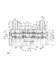
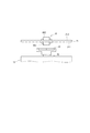
駆動装置800の構造を図3〜図6に示す。図4に示すように、モータ部10は、巻線組11、12(図2参照。)が巻回されるステータ、ロータ、および、シャフト15等を備える。ステータは、モータケース17の内側に固定される。ロータは、ステータに対して相対回転可能に設けられる。ロータの軸中心には、シャフト15が固定される。これにより、シャフト15とロータとが一体となって回転する。
The structure of the
シャフト15のコントローラ部20とは反対側の端部には、減速ギア109(図1参照。)と接続される図示しない出力端が設けられる。これにより、ロータおよびシャフト15の回転により生じるトルクが、減速ギア109を経由してステアリングシャフト102に伝達される。本明細書では、適宜、ロータおよびシャフト15が回転することを、単に「モータ部10が回転する」という。
また、シャフト15のコントローラ部20側の端部には、シャフト15と一体に回転するマグネット16が設けられる。ここで、マグネット16の中心を通り、シャフト15の軸線を延長した仮想線を回転中心線Acとする。
An output end (not shown) connected to the reduction gear 109 (see FIG. 1) is provided at the end of the
A
モータケース17は、筒部171を有し、略円筒状に形成される。モータケース17の径方向内側には、ステータ、ロータおよびシャフト15等が収容される。
フレーム部材18は、ステータおよびロータのコントローラ部20側に設けられ、例えば圧入等により、モータケース17の径方向内側に固定される。本実施形態では、モータケース17およびフレーム部材18が、モータ部10の外郭をなしている。フレーム部材18には、シャフト15が挿通され、マグネット16がコントローラ部20側に露出する。
The
The
フレーム部材18のコントローラ部20側の端面181には、基板固定部185、186が立設される。第1基板固定部185には、第1基板21が載せ置かれ、ねじ195により固定される。第2基板固定部186は、端面181からの高さが第1基板固定部185より高くなるように形成される。第2基板固定部186は、第1基板21の図示しない孔部に挿通される。第2基板固定部186には、第2基板22が載せ置かれ、ねじ196により固定される。基板21、22とフレーム部材18とは、ねじ以外にて固定してもよい。
第1巻線組11の各相のコイル111〜113および第2巻線組12の各相のコイル121〜123は、それぞれ図示しないモータ線と接続される。モータ線は、フレーム部材18に形成される図示しないモータ線挿通孔に挿通されてコントローラ部20側に取り出され、第1基板21と接続される。
The
モータ部10の軸方向の一方側には、コントローラ部20が設けられる。コントローラ部20は、モータケース17を軸方向に投影した投影領域であるモータシルエット内に収まるように設けられる。以下、モータ部10の軸方向および径方向を、駆動装置800としての「軸方向」、「径方向」とし、単に「軸方向」、「径方向」という。
A
コントローラ部20は、各種電子部品が実装される基板21、22、および、コネクタユニット70等を有する。
第1基板21および第2基板22は、フレーム部材18の端面181に対して略水平に設けられる。本実施形態では、モータ部10側から、第1基板21、第2基板22の順に配置される。ここで、第1基板21のモータ部10側の面を第1面211、モータ部10と反対側の面を第2面212とし、第2基板22のモータ部10側の面を第1面221、モータ部10と反対側の面を第2面222とする(図5および図6参照)。
The
The
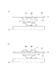
図4および図5に示すように、第1基板21の第1面211には、SW素子301〜306、401〜406、電流検出素子311〜313、411〜413、および、センサパッケージ65等が実装される。
第1基板21の第2面212には、チョークコイル35、45、および、コンデンサ36、46等が実装される。
なお、図4では、SW素子301、302、401、402が表れているものとして記載した。また、構造図において、電流検出素子311〜313、411〜413、および、チョークコイル35、45等の図示を省略した。
As shown in FIGS. 4 and 5, the
Choke coils 35 and 45,
In FIG. 4, the
SW素子301〜306、401〜406は、フレーム部材18に放熱可能に設けられる。これにより、SW素子301〜306、401〜406の熱は、フレーム部材18を経由して、モータケース17から駆動装置800の外部に放熱される。
ここで、「放熱可能に設けられる」とは、SW素子301〜306、401〜406がフレーム部材18に直接的に当接することに限らず、例えば放熱ゲル等の放熱部材を介して当接している状態も含む。図4では、放熱部材が省略されているため、SW素子301〜306、401〜406とフレーム部材18とが離間している。なお、電流検出素子311〜313、411〜413等、SW素子以外の部品を発熱素子とみなし、フレーム部材18に放熱可能に設けてもよい。
The
Here, “provided that heat can be dissipated” is not limited to the
本実施形態では、フレーム部材18をヒートシンクとして機能させている。換言すると、フレーム部材18は、モータ部10の外郭としての機能と、ヒートシンクとしての機能を兼ね備えている。これにより、別途にヒートシンクを設ける場合と比較して、部品点数を低減可能であるとともに、体格を小型化することができる。また、フレーム部材18をヒートシンクとして利用することで、大気への熱伝達経路を短くすることができ、高効率に放熱可能である。
In the present embodiment, the
図4および図6に示すように、第2基板22の第1面221には集積回路56、57が実装され、第2面222にはマイコン51、52が実装される。
すなわち、本実施形態では、モータ電流が通電される駆動部品が第1基板21に実装され、制御部品が第2基板22に実装される。換言すると、第1基板21をパワー基板、第2基板22を制御基板とし、基板を分けることでパワー部と制御部とが分離されている。これにより、制御基板である第2基板22には、ノイズ源となり得る大電流が流れないので、制御部品におけるノイズの影響が低減される。
基板21、22には、ばね端子26が設けられる。
As shown in FIGS. 4 and 6,
In other words, in the present embodiment, the drive component that is energized with the motor current is mounted on the
図3および図4に示すように、コネクタユニット70は、カバー部71、給電コネクタ75、76、および、信号コネクタ77、78を有する。
カバー部71は、略有底筒状に形成され、筒部711、および、コネクタ形成部715を有する。筒部711の先端部712は、モータケース17の筒部171に形成される溝部172に挿入され、接着剤等で固定される。
As shown in FIGS. 3 and 4, the
The
コネクタ形成部715のモータ部10と反対側には、給電コネクタ75、76、および、信号コネクタ77、78が形成される。コネクタ75〜78は、モータシルエット内に配置される。本実施形態のコネクタ75〜78は、間口がモータ部10と反対側に開口しており、ハーネス等が軸方向に挿入される。
図2〜図4に示すように、第1給電コネクタ75は、第1バッテリ39およびグランドとの接続に用いられる。第1給電コネクタ75には、第1電源端子751および第1グランド端子752が設けられる。第2給電コネクタ76は、第2バッテリ49およびグランドとの接続に用いられる。第2給電コネクタ76には、第2電源端子761および第2グランド端子762が形設けられる。
As shown in FIGS. 2 to 4, the first
第1信号コネクタ77および第2信号コネクタ78は、トルクセンサ103および図示しないCAN(Controller Area Network)との接続に用いられる。
第1信号コネクタ77には、トルクセンサ103からの信号の入力に用いられる第1トルク信号端子771、および、CANからの信号の入力に用いられる第1車両信号端子772が設けられる。第2信号コネクタ78には、トルクセンサ103からの信号の入力に用いられる第2トルク信号端子781、および、CANからの信号の入力に用いられる第2車両信号端子782が設けられる。
給電コネクタ75、76、および、信号コネクタ77、78の間口をそれぞれ複数設けることで、接続される一部の配線が外れたり、断線したりした場合にも、モータ部10の駆動を継続可能である。
The
The
By providing a plurality of openings for the
内部信号端子717は、カバー部71のコネクタ形成部715のモータ部10側に設けられる。内部信号端子717は、第1基板21および第2基板22に接続され、第1基板21と第2基板22との間の信号伝達に用いられる。内部信号端子717は、コネクタ75〜78の端子751、752、761、762、771、772、781、782とは別途に設けられており、バッテリ39、49、トルクセンサ103およびCAN等、駆動装置800の外部とは接続されていない。本実施形態では、内部信号端子717は、回転検出装置1の検出値を第2基板22に実装されるマイコン51、52等の電子部品に伝達するのに用いられる。また、内部信号端子717は、マイコン51、52からの指令信号を第1基板21に実装される電子部品に伝達するのに用いられる。
The
なお、第1給電コネクタ75における端子数や配置、割り振り等は、適宜変更可能である。第2給電コネクタ76、信号コネクタ77、78についても同様である。また、内部信号端子717は、コネクタ75〜78の各端子と干渉しない箇所であれば、いずれの箇所に形成してもよく、本数についても、図示した本数に限らない。
In addition, the number of terminals, arrangement, allocation, and the like in the first
各端子751、752、761、762、771、772、781、782、717は、基板21、22に設けられるばね端子26に挿通される。ばね端子26は、端子が挿通されることで、弾性変形しつつ、端子と当接する。これにより、各端子751、752、761、762、771、772、781、782、717は、基板21、22と電気的に接続される。
Each terminal 751, 752, 761, 762, 771, 772, 781, 782, 717 is inserted into a
本実施形態では、第1基板21および第2基板22と接続する端子751、752、761、762、717は、軸方向に投影したときに2枚の基板が重複する重複領域にて、第2基板22を貫通し、第1基板21側まで延びて形成される。また、端子751、752、761、762、717は、第1基板21および第2基板22のそれぞれに設けられるばね端子26に挿通されることで、第1基板21および第2基板22と接続される。
これにより、冗長化に伴う配線スペースの増大を防ぐことができる。
また、端子を略真っ直ぐに形成し、複数の基板21、22を貫く構造とすることで、端子を短くすることができる。これにより、配線のインピーダンスを低減することができる。
In the present embodiment, the
Thereby, an increase in wiring space due to redundancy can be prevented.
In addition, the terminals can be shortened by forming the terminals substantially straight and penetrating the plurality of
以下、回転検出装置1について説明する。
図4、図5、および、図7〜図9に示すように、回転検出装置1は、モータ部10の回転を検出するものであって、第1センサ部61および第2センサ部62、ならびに、第1マイコン51および第2マイコン52を備える。本実施形態では、第1マイコン51および第2マイコン52が「制御部」に対応する。
第1センサ部61および第2センサ部62は、1つのセンサパッケージ65内に設けられている。センサ部61、62を1パッケージとすることで、実装面積を抑えることができる。
Hereinafter, the
As shown in FIGS. 4, 5, and 7 to 9, the
The
図9に示すように、第1センサ部61は、センサ素子601、および、回路部610を有し、センサ素子601および回路部610が1つのチップ641として構成されている。換言すると、回路部610を構成するチップ641には、センサ素子601が内蔵されている。
第2センサ部62は、センサ素子602、および、回路部620を有し、センサ素子602および回路部620が1つのチップ642として構成されている。換言すると、回路部620を構成するチップ642には、センサ素子602が内蔵されている。
センサ素子601、602は、例えばGMR、AMR、TMR等のMR素子、または、ホール素子等である。
As shown in FIG. 9, the
The
The
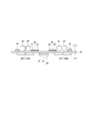
図4および図7(a)に示すように、センサパッケージ65は、第1基板21の第1面211に実装される。第1面211に実装することで、マグネット16との距離を短く設定できるので、検出精度が高まる。また、マグネット16の厚みや径を小さくすることができる。また、図7(b)に示すように、センサパッケージ65を、第1基板21の第2面212に実装してもよい。第2面212に実装することで、第1面211にSW素子301〜306、401〜406以外の発熱素子をフレーム部材18に放熱可能に実装する等、第1面211を有効に活用することができる。なお、図7では、回転検出装置1のセンサパッケージ65以外の実装部品等を省略した。後述の図27、図28および図31も同様である。
As shown in FIGS. 4 and 7A, the
図8および図9に示すように、センサパッケージ65は、略矩形に形成され、両側にセンサ端子67が設けられる。センサ端子67には、指令端子671、673、出力端子672、674、電源端子675、677およびグランド端子676、678が含まれる。
センサパッケージ65には、定電圧源37、47および電源端子675、677等を経由してバッテリ39、49から電力が供給される。本実施形態では、第1センサ部61には、定電圧源37および電源端子675等を経由して、第1バッテリ39から電力が供給され、第2センサ部62には、定電圧源47および電源端子677等を経由して、第2バッテリ49から電力が供給される。なお、1つのバッテリから、第1センサ部61および第2センサ部62に電力が供給されるようにしてもよい。1つのバッテリからセンサ部61、62に電力が供給されるように構成する場合、定電圧源を共用してもよいし、センサ部61、62ごとに設けてもよい。後述の実施形態についても同様である。
As shown in FIGS. 8 and 9, the
Electric power is supplied to the
定電圧源37、47は、センサ部61、62を駆動できる程度(例えば数mA程度)の電力消費量が小さいレギュレータ等である。定電圧源37、47は、集積回路56、57のレギュレータとは別途に設けられ、駆動装置800の停止中にもセンサパッケージ65に電力供給可能なものである。
グランド端子676、678は、グランドと接続される。
The
The
図8に示すように、第1センサ部61を構成するチップ641および第2センサ部62を構成するチップ642は、いずれもセンサパッケージ65に内蔵されるリードフレーム66に実装される。チップ641、642とセンサ端子67とは、ワイヤ等により接続される。また、センサ端子67は、第1基板21の配線パターンと接続される。これにより、センサ部61、62と第1基板21とが接続される。
As shown in FIG. 8, the
センサ素子601、602は、シャフト15と一体となって回転するマグネット16の回転に伴う磁界の変化を検出する磁気検出素子である。本実施形態のセンサ素子601、602は、ホール素子である。本実施形態では、モータ部10、より詳細にはモータ部10のシャフト15と一体に回転するマグネット16が、「検出対象」に対応する。
センサ素子601、602は、回転中心線Acと第1基板21との交点に対して点対称に配置される。以下、回転中心線Acと第1基板21との交点に対して点対称に配置されることを、単に「回転中心線Acに対して点対称に配置される」という。センサ素子601、602を回転中心線Acに対して点対称配置とすることで、素子間の検出誤差を低減することができる。
The
The
図9に示すように、回路部610は、回転角演算部614、回転回数演算部615、および、通信部619を有する。回路部620は、回転角演算部624、回転回数演算部625、および、通信部629を有する。
回路部610、620において、3桁符番の下1桁が同じである構成は略同様であるので、以下、回路部610を中心に説明する。
As illustrated in FIG. 9, the
In the
回転角演算部614は、センサ素子601の検出値に基づき、モータ部10の回転角θmを演算する。センサ素子601の検出値は、必要に応じ、AD変換等の処理がなされた値とする。回転回数TCの演算に用いられる値についても同様である。回転角演算部614にて演算される値は、回転角θmそのものに限らず、第1マイコン51にて回転角θmを演算可能などのような値であってもよい。このような場合も含め、以下単に「回転角θmの演算」とする。回転回数演算部615における回転回数TCの演算についても同様とする。
本実施形態では、回転角θmを機械角とするが、電気角としてもよい。
The rotation
In the present embodiment, the rotation angle θm is a mechanical angle, but may be an electrical angle.
回転回数演算部615は、センサ素子601の検出値に基づき、モータ部10の回転回数TCを演算する。回転回数TCは、例えばモータ部10の1回転を3以上の領域に分け、領域が変わるごとに回転方向に応じてカウントアップまたはカウントダウンすることで、カウント値に基づいて演算可能である。また、カウント値そのものについても、「回転回数TC」の概念に含まれるものとする。
The rotation
回転回数演算部615は、モータ部10の1回転を3領域以上に分割してカウントすることで、回転方向を判別可能である。また、1回転の領域数を5領域以上とすれば、読み飛ばしが生じたときにも回転方向を判別可能である。また、回転回数TCを回転角θmから演算するようにしてもよい。
なお、本明細書でいう「回転回数」とは、単位rpm等で表される、いわゆる回転数(回転速度)ではなく、「ロータが何回転したか」を表す値である。また、本明細書では、単位rpm等で表される、いわゆる「回転数」については、「回転速度」とする。
The rotation
The “number of rotations” in this specification is not a so-called rotation number (rotation speed) expressed in unit rpm or the like but a value indicating “how many times the rotor has rotated”. Further, in this specification, the so-called “rotation speed” expressed in unit rpm or the like is referred to as “rotation speed”.
通信部619は、回転角θmに係る回転角信号、および、回転回数TCに係る回転回数信号を含む出力信号を生成し、SPI(Serial Peripheral Interface)通信等のデジタル通信により、出力信号を第1マイコン51に出力する。本実施形態では、第1マイコン51からの指令が、通信線691および指令端子671から第1センサ部61に入力される。第1センサ部61は、第1マイコン51からの指令を受信すると、出力端子672および通信線692を経由して第1マイコン51に出力信号を出力する。出力信号の通信フレームには、回転角θmに係る情報、回転回数TCに係る情報に加え、ランカウンタ信号および誤り検出信号としてのCRC信号等が含まれる。図10等では、ランカウンタ信号の記載を省略した。なお、誤り検出信号は、例えばチェックサム信号等、CRC信号以外のものであってもよい。
The
第2センサ部62の通信部619は、センサ素子602の検出値に基づいて回転角演算部624にて演算された回転角θmに係る回転角信号、および、回転回数演算部625にて演算された回転回数TCに係る回転回数信号を含む出力信号を生成し、第2マイコン52に出力する。本実施形態では、第2マイコン52からの指令が通信線693および指令端子673から第2センサ部62に入力される。第2センサ部62は、第2マイコン52からの指令を受信すると、出力端子674および通信線694を経由して第2マイコン52に出力信号を出力する。
なお、本実施形態では、マイコン51、52がいずれも第2基板22に実装されているので、通信線691〜694は、基板21、22における基板配線、および、内部信号端子717により構成される。
The
In the present embodiment, since both the
第1マイコン51は、第1センサ部61から取得した出力信号に含まれる回転角信号に基づき、モータ部10の回転角θmを演算する。演算された回転角θmは、モータ部10の駆動制御に用いられる。
また、第1マイコン51は、第1センサ部61から取得した出力信号に含まれる回転角信号、および、回転回数信号に基づき、ステアリングシャフト102の舵角θsを演算する。ステアリングシャフト102は減速ギア109を介してモータ部10と接続されているので、舵角θsは、回転角θm、回転回数TC、および、減速ギア109のギア比に基づいて演算可能である。第2マイコン52においても、第2センサ部62から取得した出力信号に基づき、同様の演算を行う。
The
Further, the
電動パワーステアリング装置108が搭載される図示しない車両が直進するときのステアリングホイール101の位置である中立位置は、例えば一定速度で直進進行を一定時間行うことで、学習可能である。学習された中立位置は、マイコン51、52に記憶される。本実施形態では、マイコン51、52は、中立位置を基準とし、回転角θm、回転回数TCおよび減速ギア109のギア比に基づいて舵角θsを演算する。マイコン51、52にて回転角θm等に基づいて舵角演算を行うことで、ステアリングセンサを省略することができる。
本実施形態では、舵角θsは、ステアリングシャフト102の下側の回転角とする。ステアリングシャフト102の下側は、減速ギア89を介してモータ部10と接続されているので、舵角θsは、回転角θm、回転回数TC、および、減速ギア89のギア比に基づいて演算可能である。また、トーションバーの捩れ量に基づいて換算すれば、ステアリングシャフト102の上側の回転角も演算可能であるので、ステアリングシャフト102の上側の回転角を舵角θsとしてもよい。
The neutral position, which is the position of the
In the present embodiment, the steering angle θs is the lower rotation angle of the
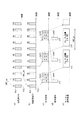
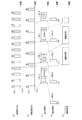
センサ部61、62とマイコン51、52との間における通信について、図10に基づいて説明する。図10では、(a)がセンサ部における回転角θmの演算処理、(b)がセンサ部における回転回数TCの演算処理、(c)がセンサ部61から第1マイコン51へ送信される出力信号、(d)が第1マイコン51からセンサ部61へ送信される指令信号、(e)がマイコンにおける演算処理を示す。
なお、第1センサ部61と第1マイコン51との間での通信と、第2センサ部62と第2マイコン52との間での通信とは略同様であるので、ここでは、第1センサ部61と第1マイコン51との間での通信について説明する。
Communication between the
In addition, since the communication between the
図10(a)に示すように、回転角θmは、更新周期DRT_saで更新される。図10(a)における各パルスは、回転角演算部614における回転角θmのデータ更新に係る演算期間を示している。各パルスの前半の期間Px1にて、センサ素子601の検出値をデジタル変換し、期間Px1に続く期間Px2にて、回転角演算部614が回転角θmを演算し、回転角θmに係るデータを更新する。図10(a)では、回転角θmに係るデータが、1A、2A、・・・11Aと更新されていくものとする。なお、図10(a)では、データ1Aの演算期間について、期間Px1、Px2を記載しているが、他のデータの演算期間についても同様である。
As shown in FIG. 10A, the rotation angle θm is updated at the update cycle DRT_sa. Each pulse in FIG. 10A indicates a calculation period related to data update of the rotation angle θm in the rotation
図10(b)に示すように、回転回数TCは、更新周期DRT_sbで更新される。図10(b)における各パルスは、回転回数演算部615における回転回数TCのデータ更新に係る演算期間を示している。各パルスの前半期間のPy1にて、センサ素子601の検出値をデジタル変換し、期間Py1に続く期間Py2にて、回転回数演算部615が回転回数TCを演算し、回転回数TCに係るデータを更新する。図10(b)では、回転回数TCに関するデータが、1B、2B、・・・11Bと更新されていくものとする。なお、図10(b)では、データ1Bの演算期間について、期間Py1、Py2を記載しているが、他のデータの演算期間についても同様である。
以下、nを任意の自然数とし、「nA」が回転角θmに係るデータおよび当該データに基づく回転角信号を意味し、「nB」が回転回数TCに係るデータおよび当該データに基づく回転回数信号を意味するものとする。
図11、図15および図30についても同様である。
As shown in FIG. 10B, the number of rotations TC is updated at the update cycle DRT_sb. Each pulse in FIG. 10B indicates a calculation period related to data update of the rotation number TC in the rotation
Hereinafter, n is an arbitrary natural number, “nA” means the data related to the rotation angle θm and the rotation angle signal based on the data, and “nB” means the data related to the rotation frequency TC and the rotation frequency signal based on the data. Shall mean.
The same applies to FIGS. 11, 15, and 30.
図10(a)、(b)に示すように、本実施形態では、回転角θmの更新周期DRT_saと、回転回数TCの更新周期DRT_sbとは等しく、第1マイコン51における演算周期DRT_mと比較して短い。
As shown in FIGS. 10A and 10B, in this embodiment, the update cycle DRT_sa of the rotation angle θm and the update cycle DRT_sb of the number of rotations TC are equal and compared with the calculation cycle DRT_m in the
図10(c)、(d)に示すように、時刻x11にて、第1マイコン51は、次の指令送信のタイミングにて出力信号の送信を要求する指令信号com1を第1センサ部61に送信する。また、通信部619は、指令信号com1を受信したタイミングである時刻x11にて、指令信号com1の直前の指令信号com0(不図示)に基づく出力信号Sd10を第1マイコン51に送信する。
出力信号Sd10には、最新データに基づく回転角θmおよび回転回数TCに係る信号、および、CRC信号が含まれる。詳細には、出力信号Sd10には、データ1Aに基づく回転角信号、データ1Bに基づく回転回数信号、および、回転角信号および回転回数信号に基づいて演算される巡回冗長検査信号であるCRC信号が含まれる。
As shown in FIGS. 10C and 10D, at time x11, the
The output signal Sd10 includes a signal related to the rotation angle θm and the number of rotations TC based on the latest data, and a CRC signal. Specifically, the output signal Sd10 includes a rotation angle signal based on the
第1マイコン51は、時刻x12にて、出力信号Sd10に含まれる回転角信号および回転回数信号に基づく回転角θmおよび舵角θsの演算を開始する。図10における[1A、1B]の記載は、回転角θmおよび舵角θsの演算にデータ1A、1Bを用いることを意味する。なお、舵角θsは、必ずしも毎回演算しなくてもよく、例えば所定回数に1回の割合で演算するようにしてもよい。
The
また、時刻x13にて、第1マイコン51から指令信号com2が送信されると、第1センサ部61は、データ4Aに基づく回転角信号、データ4Bに基づく回転回数信号、および、CRC信号を含む出力信号Sd11を第1マイコン51に送信する。第1マイコン51は、時刻x14にて、出力信号Sd11に含まれる信号に基づく回転角θmおよび舵角θsの演算を開始する。
時刻x15にて、第1マイコン51から指令信号com3が送信されると、第1センサ部61は、データ8Aに基づく回転角信号、データ8Bに基づく回転回数信号、および、CRC信号を含む出力信号Sd12を第1マイコン51に送信する。
Further, when the command signal com2 is transmitted from the
When the command signal com3 is transmitted from the
図11に示すように、更新周期DRT_sa、DRT_sbは、異なっていてもよい。詳細には、回転回数TCの更新周期DRT_sbは、回転角θmの更新周期DRT_saより長くてもよい。回転角θmの更新周期DRT_saは、第1マイコン51の演算周期DRT_mより十分に短い必要がある。一方、回転回数TCは、モータ部10の1回転を3分割した各象限を読み飛ばすことなく検出すれば、逆回転も検出可能であり、回転回数を誤検出することがない。そのため、回転回数TCの更新周期DRT_sbは、モータ部10の設定回転速度に応じ、読み飛ばしがないような長さに適宜設定すればよい。なお、設定回転速度は、モータ部10の最大回転速度としてもよいし、回転回数TCのカウントを要する所定の回転速度としてもよい。
As shown in FIG. 11, the update periods DRT_sa and DRT_sb may be different. Specifically, the update cycle DRT_sb of the number of rotations TC may be longer than the update cycle DRT_sa of the rotation angle θm. The update cycle DRT_sa of the rotation angle θm needs to be sufficiently shorter than the calculation cycle DRT_m of the
図11の例では、時刻x21、x22での処理は、図10中の時刻x11、x12の処理と同様であり、第1センサ部61は、時刻x21にて、データ1Aに基づく回転角信号およびデータ1Bに基づく回転回数信号を含む出力信号Sd21を第1マイコン51に送信する。第1マイコン51は、時刻x22にて、出力信号Sd21に基づく回転角θmおよび舵角θsの演算を開始する。
In the example of FIG. 11, the processes at times x21 and x22 are the same as the processes at times x11 and x12 in FIG. 10, and the
時刻x23にて、第1マイコン51から指令信号com2が送信されると、第1センサ部61は、データ4Aに基づく回転角信号およびデータ3Bに基づく回転回数信号を含む出力信号Sd22を第1マイコン51に送信する。第1マイコン51は、時刻x24にて、出力信号Sd22に基づく回転角θmおよび舵角θsの演算を開始する。
時刻x25にて、第1マイコン51から指令信号com3が送信されると、第1センサ部61は、データ8Aに基づく回転角信号、および、データ4Bに基づく回転回数信号を含む出力信号Sd23を第1マイコン51に送信する。
When the command signal com2 is transmitted from the
When the command signal com3 is transmitted from the
ここで、参考例による通信を図30に示す。参考例では、回転角を検出するセンサ部と、回転回数を検出するセンサ部とが別々のチップに設けられており、回転角信号と回転回数信号とを別々の信号として送信する例である。ここでは、SPI通信におけるチップセレクトに応じて各チップからの信号が交互に送信されるものとする。また、更新周期DRT_sa、DRT_sbは、図11と同様とする。 Here, communication according to the reference example is shown in FIG. In the reference example, the sensor unit that detects the rotation angle and the sensor unit that detects the number of rotations are provided in separate chips, and the rotation angle signal and the rotation number signal are transmitted as separate signals. Here, it is assumed that signals from each chip are alternately transmitted according to chip selection in SPI communication. The update cycles DRT_sa and DRT_sb are the same as those in FIG.
時刻x91では、指令信号com1cの直前の指令信号com0c(不図示)に基づいて出力信号Sd91が送信される。出力信号Sd91には、データ1Aに基づく回転角信号が含まれる。一方、出力信号Sd91には、回転回数信号が含まれない。
時刻x92では、出力信号Sd91に含まれるデータ1A、および、指令信号com0cが送信されたタイミングで送信される出力信号Sd90(不図示)に含まれるデータ−1Bに基づき、回転角θmおよび舵角θsが演算される。
At time x91, an output signal Sd91 is transmitted based on a command signal com0c (not shown) immediately before the command signal com1c. The output signal Sd91 includes a rotation angle signal based on the
At time x92, the rotation angle θm and the steering angle θs are based on the
時刻x93では、指令信号com2cが送信されると、データ3Bに基づく回転回数信号を含む出力信号Sd92が送信される。また、時刻x94では、指令信号com3cが送信されると、データ8Aに基づく回転角信号を含む出力信号Sd93が送信される。
時刻x95では、出力信号Sd93に含まれるデータ8Aに基づく回転回数信号、および、出力信号Sd92に含まれるデータ3Bに基づく回転回数信号を用いて、回転角θmおよび舵角θsが演算される。
At time x93, when the command signal com2c is transmitted, an output signal Sd92 including a rotation number signal based on the
At time x95, the rotation angle θm and the steering angle θs are calculated using the rotation frequency signal based on the
参考例では、回転角θmの検出に用いられるセンサ部と、回転回数TCの検出に用いられるセンサ部とが別々であるので、回転角信号と回転回数信号とは別途にマイコンに送信される。そのため、例えば時刻x95における演算に用いられる回転角信号の検出タイミングと回転回数信号の検出タイミングとのずれ幅Tdcは、マイコンの指令周期よりも長い。参考例のように、検出タイミングのずれが大きい回転角θmおよび回転回数TCを用いると、舵角θsを正確に演算できない虞がある。 In the reference example, since the sensor unit used for detecting the rotation angle θm and the sensor unit used for detecting the rotation number TC are separate, the rotation angle signal and the rotation number signal are separately transmitted to the microcomputer. Therefore, for example, the deviation width Tdc between the detection timing of the rotation angle signal and the detection timing of the rotation frequency signal used for the calculation at time x95 is longer than the command period of the microcomputer. As in the reference example, when the rotation angle θm and the number of rotations TC with a large detection timing shift are used, the steering angle θs may not be accurately calculated.
そこで本実施形態では、回転角演算部614および回転回数演算部615を1つのチップ641として構成し、回転角信号と回転回数信号とを一連の出力信号として、通信部619から第1マイコン51に送信している。
そのため、図10に示すように、回転角θmに係るデータと回転回数TCに係るデータとの更新タイミングが同時であれば、第1マイコン51では、同時に検出された検出値に基づいて、回転角θm、回転回数TC、および、舵角θsを演算することができる。
また、図11に示すように、更新周期DRT_sa、DRT_sbが異なっていても、同一の出力信号に回転角信号および回転回数信号を含めて送信することで、検出タイミングのずれ幅Tdは、マイコン51からの指令周期より短くなり、参考例のように別々の信号として送信する場合と比較し、検出タイミングのずれを低減することができる。
Therefore, in this embodiment, the rotation
Therefore, as shown in FIG. 10, if the update timing of the data related to the rotation angle θm and the data related to the number of rotations TC are the same, the
As shown in FIG. 11, even if the update periods DRT_sa and DRT_sb are different, the detection timing deviation Td can be obtained by transmitting the same output signal including the rotation angle signal and the rotation frequency signal to the
また、本実施形態では、回転角度信号および回転回数信号を一連の出力信号に含め、1本の通信線692を経由して第1マイコン51に送信される。これにより、回転角度信号と回転回数信号とを別々の通信線を用いてマイコンに送信する場合と比較して、通信線の数を減らすことができる。
In the present embodiment, the rotation angle signal and the rotation frequency signal are included in a series of output signals and transmitted to the
本実施形態の駆動装置800は、電動パワーステアリング装置108に設けられる。電動パワーステアリング装置108は、車両の基本機能の1つである「曲がる」機能を司る装置であるため、冗長構成とすることで、一部に異常が生じた場合であっても操舵のアシストを継続できるようにしている。一方、居住スペースの拡大や燃費向上の面から、駆動装置800には小型化が求められる。
The
本実施形態では、回路部610、620を複数設けることで、回転角θmおよび回転回数TCの演算機能が冗長化されており、いずれか一方に異常が生じた場合であっても、電動パワーステアリング装置108の動作を継続可能である。また、回路部610、620をそれぞれ1チップとして一体化することで、回転検出装置1を小型化可能であるので、駆動装置800の小型化に寄与する。
In the present embodiment, by providing a plurality of
以上説明したように、本実施形態の回転検出装置1は、センサ部61、62と、マイコン51、52と、を備える。
第1センサ部61は、センサ素子601、および、回路部610を有する。第2センサ部62は、センサ素子602、および、回路部620を有する。
センサ素子601、602は、モータ部10の回転を検出する。回路部610、620は、センサ素子601、602の検出値に基づく出力信号を生成して出力する。
マイコン51、52は、センサ部61、62から出力信号を取得し、出力信号に基づく演算を行う。
As described above, the
The
The
The
回路部610は、回転角演算部614、回転回数演算部615、および、通信部619を有する。回転角演算部614は、センサ素子601の検出値に基づいてモータ部10の回転角θmを演算する。回転回数演算部615は、センサ素子601の検出値に基づいてモータ部10の回転回数TCをカウントする。通信部619は、回転角θmに係る信号である回転角信号および回転回数TCに係る信号である回転回数信号を含む一連の信号である出力信号を第1マイコン51に送信する。
The
回路部620は、回転角演算部624、回転回数演算部625、および、通信部629を有する。回転角演算部624は、センサ素子602の検出値に基づいてモータ部10の回転角θmを演算する。回転回数演算部625は、センサ素子602の検出値に基づいてモータ部10の回転回数TCをカウントする。通信部629は、回転角θmに係る信号である回転角信号および回転回数TCに係る信号である回転回数信号を含む一連の信号である出力信号を第2マイコン52に送信する。
The
回転角信号および回転回数信号が一連の出力信号に含まれるので、回転角信号および回転回数信号を1回の通信でマイコン51、52に送信可能である。これにより、回転角θmに係る検出値と回転回数TCに係る検出値との検出タイミングのずれを低減することができる。また、1本の通信線692にて、回転角信号および回転回数信号を通信部619から第1マイコン51に送信することができる。同様に、1本の通信線694にて、回転角信号および回転回数信号を通信部629から第2マイコン52に送信することができる。これにより、回転角信号および回転回数信号ごとに通信線を設ける場合と比較し、通信線の数を減らすことができる。
Since the rotation angle signal and the rotation frequency signal are included in the series of output signals, the rotation angle signal and the rotation frequency signal can be transmitted to the
回転角演算部614および回転回数演算部615は、同一のセンサ素子601の検出値に基づいて回転角θmまたは回転回数TCを演算する。回転角演算部624および回転回数演算部625は、同一のセンサ素子602の検出値に基づいて回転角θmまたは回転回数TCを演算する。回転角θmおよび回転回数TCの演算に用いるセンサ素子を共通とすることで、センサ数を低減することができる。
The rotation
バッテリ39、49からセンサ部61、62への電力供給路には、定電圧源37、47が設けられる。バッテリ39、49とセンサ部61、62との間に定電圧源37、47を設けることで、バッテリ39、49の電圧によらず、センサ部61、62の耐圧設計を変更する必要がない。
回転検出装置1には、センサ部61、62が複数設けられる。第1センサ部61には、センサ素子601および回路部610が含まれる。第2センサ部62には、センサ素子602および回路部620が含まれる。全てのセンサ部61、62は、1つのパッケージ65内に設けられる。
The
センサ部61、62を複数設けることで、一方のセンサ部に異常が生じた際も、他方のセンサ部にてモータ部10の回転角θmおよび回転回数TCの検出を継続することができる。
また、図31に示す参考例のように、回転角θmの演算に係るパッケージ656、657と、回転回数TCの演算に係るパッケージ658、659とをそれぞれ別途に設ける場合と比較し、実装面積を抑えることができる。これにより、例えば第1基板21の第1面211側の面にSW素子301〜306、401〜406等のフレーム部材18への放熱を要する素子の実装領域を確保することができる。また、センサ素子601、602を回転中心線Acに近づけて配置できるので、マグネット16を小型化可能であるとともに、検出精度の悪化を防ぐことができる。特に、センサ素子601、602を回転中心線Acに対して点対称配置することで、素子間の検出誤差を低減することができる。
By providing a plurality of
In addition, as in the reference example shown in FIG. 31, compared with the case where the
センサ部561、562、および、センサ部561、562から出力信号を取得するマイコン51、52の組み合わせは複数である。詳細には、第1センサ部561と第1マイコン51との組み合わせ、および、第2センサ部562と第2マイコン52との組み合わせの2組が設けられている。これにより、一方の系統に異常が生じた場合であっても、他方の系統にて演算を継続することができる。
There are a plurality of combinations of the
電動パワーステアリング装置108は、モータ部10と、回転検出装置1と、マイコン51、52と、を備える。モータ部10は、運転者による操舵を補助する補助トルクを出力する。マイコン51、52は、出力信号に含まれる信号を用いてモータ部10を制御する。センサ素子601、602は、検出対象としてモータ部10の回転を検出する。
また、マイコン51、52は、回転角θm、および、回転回数TCに基づき、舵角θsを演算する。
The electric
Further, the
これにより、例えばステアリングシャフト102にギア等を設けて舵角θsを検出するステアリングセンサを省略することができる。また、回転角信号および回転回数信号を1回の通信でマイコン51、52に送信することで、回転角θmに係る検出値と回転回数TCに係る検出値との検出タイミングのずれを抑えているので、舵角θsを適切に演算することができる。
Thus, for example, a steering sensor that detects the steering angle θs by providing a gear or the like on the
(第2実施形態)
本発明の第2実施形態を図12および図13に示す。本実施形態は、回転検出装置2が上記実施形態と異なっており、それ以外の構成については上記実施形態と同様であるので、説明を省略する。図12および後述の図14、図23では、バッテリ39、49の記載を省略した。
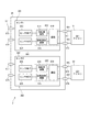
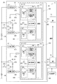
図12に示すように、本実施形態の回転検出装置2は、第1センサ部261、第2センサ部262、第1マイコン51および第2マイコン52を備える。
(Second Embodiment)
A second embodiment of the present invention is shown in FIGS. In the present embodiment, the
As shown in FIG. 12, the
第1センサ部261は、回転角用のセンサ素子603、回転回数用のセンサ素子604、および、回路部610を有する。センサ素子603、604および回路部610は、1つのチップ641に設けられる。
第2センサ部262は、回転角用のセンサ素子605、回転回数用のセンサ素子606、および、回路部620を有する。センサ素子605、606および回路部620は、1つのチップ642に設けられる。チップ641、642は、1つのセンサパッケージ65に設けられる。第3実施形態〜第6実施形態においても同様である。
The
The
センサ素子603〜606は、第1実施形態のセンサ素子601、602と同様、マグネット16の回転により変化する磁束を検出するホール素子等の磁気検出素子である。
センサ部261、262とマイコン51、52との通信等については、上記実施形態と同様である。
Similar to the
The communication between the
本実施形態では、回転角θm演算用のセンサ素子603、605と、回転回数TC演算用のセンサ素子604、606とが、別途に設けられている。これにより、回転角θmまたは回転回数TCの演算に最適な素子を選定することができる。例えば、回転角θm演算用のセンサ素子603、605には、検出精度の高いのもを用い、回転回数TC演算用のセンサ素子604、606には、電力消費の少ないものを用いる、といった具合である。
In the present embodiment,
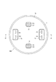
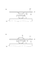
センサ素子の配置を図13に示す。
図13(a)、(b)に示すように、回転角θm演算用のセンサ素子603、605は、回転中心線Acに対して点対称に配置される。また、回転回数TC演算用のセンサ素子604、606は、回転中心線Acに対して点対称に配置される。
The arrangement of the sensor elements is shown in FIG.
As shown in FIGS. 13A and 13B, the
図13(a)では、回転角θm演算用のセンサ素子603、605が内側、回転回数TC演算用のセンサ素子604、606が外側となるように配置される。すなわち、より検出精度が要求される回転角θm演算用のセンサ素子603、605を内側に配置することで、回転中心線Acに近接させ、検出誤差を低減している。なお、回転回数TCの演算には、回転角θmと比較して検出精度が要求されないため、外側に配置している。
In FIG. 13A, the
また、図13(b)に示すように、センサ素子603、604、および、センサ素子605、606を、それぞれ回転中心線Acに対して横並びの状態にて配列してもよい。このとき、回転角θm検出用のセンサ素子603、605が点対称に配置され、回転回数TC検出用のセンサ素子604、606が点対称に配置される。
Further, as shown in FIG. 13B, the
回転角演算部614は、センサ素子603の検出値に基づいて回転角θmを演算し、回転回数演算部615は、センサ素子604の検出値に基づいて回転回数TCを演算する。
また、回転角演算部624は、センサ素子605の検出値に基づいて回転角θmを演算し、回転回数演算部625は、センサ素子606の検出値に基づいて回転回数TCを演算する。換言すると、回転角θmと回転回数TCとは、異なるセンサ素子の検出値に基づいて演算される。
The rotation
The rotation
回転角θmの演算に用いるセンサ素子603、605と、回転回数TCの演算に用いられるセンサ素子604、606とを別途に設けることで、それぞれの要求に応じたセンサ素子を選定することができる。
本実施形態では、回転角θm演算用のセンサ素子603、605が「第1のセンサ素子」に対応し、回転回数TC演算用のセンサ素子604、606が「第2のセンサ素子」に対応する。
また、上記実施形態と同様の効果を奏する。
By separately providing
In the present embodiment, the
In addition, the same effects as those of the above embodiment can be obtained.
(第3実施形態)
本発明の第3実施形態を図14および図15に示す。
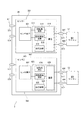
図14に示すように、本実施形態の回転検出装置3は、第1センサ部361、第2センサ部362、第1マイコン51および第2マイコン52を備える。
第1センサ部361の回路部611は、第1実施形態の回路部610の各構成に加え、自己診断部618を有する。第2センサ部362の回路部621は、第1実施形態の回路部621の各構成に加え、自己診断部628を有する。本実施形態では、センサ素子601および回路部611が1つのチップ641に設けられ、センサ素子602および回路部621が1つのチップ642に設けられる。第2実施形態のように、回転角θm演算用と、回転回数TC演算用とで、別途にセンサ素子を設ける構成としてもよい。
(Third embodiment)
A third embodiment of the present invention is shown in FIGS.
As shown in FIG. 14, the
The
自己診断部618は、センサ素子601、回転角演算部614および回転回数演算部615の天絡や地絡等の電源異常を監視する。
自己診断部628は、センサ素子602、回転角演算部624および回転回数演算部625の天絡や地絡等の電源異常を監視する。
自己診断部618、628における自己監視結果は、ステータス信号として出力信号に含め、マイコン51、52に送信する。
The self-
The self-
Self-monitoring results in the self-
第1マイコン51と第1センサ部361との間における通信について、図15に基づいて説明する。通信タイミング等については、図11と同様であるので、ここでは、第1センサ部361から送信される出力信号を、第1マイコン51からの指令に応じて変更する点を中心に説明する。なお、上記実施形態と同様、第2マイコン52と第2センサ部362との間での通信は、第1マイコン51と第1センサ部361との間での通信と略同様であるので、ここでは、第1マイコン51と第1センサ部361との間の通信を例に説明する。
Communication between the
本実施形態では、第1センサ部361は、第1マイコン51から送信される指令の種類に応じて出力信号に含まれる信号の種類を変更している。
時刻x31にて、第1マイコン51から指令信号com_aが送信されると、通信部619は、次の指令を受信したタイミングである時刻x32にて、回転角信号、回転回数信号、ステータス信号、および、CRC信号を含む出力信号Sd_aを第1マイコン51に送信する。なお、出力信号Sd_aの出力タイミングにて送信される指令は、どの信号の出力を指示するものであってもよく、種類は問わない。他の出力信号の送信タイミングに係る指令についても同様である。
In the present embodiment, the
When the command signal com_a is transmitted from the
時刻x32にて、第1マイコン51から指令信号com_bが送信されると、通信部619は、次の指令を受信したタイミングである時刻x33にて、回転角信号、回転回数信号、および、CRC信号を含む出力信号Sd_bを第1マイコン51に送信する。
時刻x33にて、第1マイコン51から指令信号com_cが送信されると、通信部619は、次の指令を受信したタイミングである時刻x34にて、回転角信号、ステータス信号、および、CRC信号を含む出力信号Sd_cを第1マイコン51に送信する。
時刻x34にて、第1マイコン51から指令信号com_dが送信されると、通信部619は、次の指令を受信したタイミングである時刻x35にて、回転角信号、および、CRC信号を含む出力信号Sd_dを第1マイコン51に送信する。
When the command signal com_b is transmitted from the
When the command signal com_c is transmitted from the
When the command signal com_d is transmitted from the
図15の例では、説明のため、第1マイコン51からの指令信号が、com_a、com_b、com_c、com_dの順に送信され、第1センサ部361からの出力信号が、Sd_a、Sd_b、Sd_c、Sd_dの順に送信されているが、この順に限らず、送信順が異なっていてもよい。また例えば、第1マイコン51は、回転回数信号を回転回数送信周期で取得し、ステータス信号をステータス送信周期で取得するように、各送信周期に応じて指令信号com_a、com_b、com_cを送信し、その他のタイミングでは回転角信号を取得する指令信号com_dを送信するようにしてもよい。回転回数送信周期とステータス送信周期とは、等しくてもよいし、異なっていてもよい。回転回数送信周期とステータス送信周期とが等しければ、指令信号com_b、com_cを用いなくてもよい。また、所定の周期に限らず、第1マイコン51にて、第1マイコン51にて回転回数TCまたは第1センサ部361における自己監視結果の取得を要するとき、適宜、指令信号com_dに替えて、指令信号com_a、com_b、com_cのいずれかを送信するようにしてもよい。
第1マイコン51では、取得された信号に応じた演算が行われる。図15(e)は、演算期間が等しいものとして記載しているが、行われる演算に応じ、演算期間が異なっていてもよい。
In the example of FIG. 15, for the sake of explanation, a command signal from the
In the
本実施形態では、自己診断部618が設けられる場合を例に説明したが、第1実施形態等、自己診断部が設けられない場合においても、指令の種類に応じ、出力信号に含まれる信号の種類を変更可能である。すなわち、自己診断部618が設けられていない場合、指令信号com_bに応じて回転角信号および回転回数信号を含む出力信号Sd_bを送信し、指令信号com_dに応じて回転角信号を含む出力信号Sd_dを送信する、といった具合である。
In the present embodiment, the case where the self-
第1マイコン51は、出力信号に含める信号の種類および送信タイミングを指示する指令信号を通信部619に送信する。通信部619は、受信した指令信号に応じ、出力信号に含める信号の種類を変更する。これにより、通信部619は、第1マイコン51の要求に応じた信号を適切に送信することができる。
The
回路部611は、回路部611における異常を判定する自己診断部618を有する。通信部619は、自己診断部618における異常判定結果に係るステータス信号を出力信号に含めて第1マイコン51に送信する。これにより、第1マイコン51にて、異常な信号を用いた演算が行われるのを防ぐことができる。
ここでは、第1マイコン51および第1センサ部361について説明したが、第2マイコン52および第2センサ部362についても同様である。後述の実施形態についても同様である。
また、上記実施形態と同様の効果を奏する。
The
Here, the
In addition, the same effects as those of the above embodiment can be obtained.
(第4実施形態)
本発明の第4実施形態を図16に示す。
図16に示すように、本実施形態の回転検出装置4は、第1センサ部461、第2センサ部462、第1マイコン51および第2マイコン52を備える。第1センサ部461は、センサ素子601、607および回路部612を有し、1つのチップ641により構成される。第2センサ部462は、センサ素子602、608および回路部622を有し、1つのチップ642により構成される。
(Fourth embodiment)
A fourth embodiment of the present invention is shown in FIG.
As shown in FIG. 16, the
第1センサ部461の回路部612は、第4実施形態の回路部611の各構成に加え、センサ素子607、回転角演算部616、および、回転回数演算部617を有する。ここで、センサ素子601、回転角演算部614および回転回数演算部615を回転情報演算回路951とし、センサ素子607、回転角演算部616および回転回数演算部617を回転情報演算回路952とする。すなわち、第1センサ部461は、2組の回転情報演算回路951、952を有している。
The
第2センサ部462の回路部622は、第4実施形態の回路部612の各構成に加え、センサ素子608、回転角演算部626、および、回転回数演算部627を有する。第2センサ部462についても同様に、センサ素子602、回転角演算部624および回転回数演算部625を回転情報演算回路953とし、センサ素子608、回転角演算部626および回転回数演算部627を回転情報演算回路954とする。すなわち、第2センサ部462は、2組の回転情報演算回路953、954を有している。補足として、例えば第1実施形態等のセンサ部61、62には、それぞれ1組の回転情報演算回路が設けられる。
The
自己診断部618は、天絡、地絡等の電源異常に加え、第1センサ部461のIC内部回路の動作異常の監視にて、回転角θmを監視する。例えば、第1センサ部461内のセンサ素子601、607の出力の異常の検出部や、演算回路の異常等による回転角θmの異常を検出する方法として、回転情報演算回路951、952の対応する値を比較し、オフセット異常等の中間異常を検出する等がある。通信部619は、自己診断部618における自己診断結果をステータス信号として出力信号に含め、第1マイコン51に送信する。
The self-
自己診断部628は、天絡、地絡等の電源異常に加え、第2センサ部462のIC内部回路の動作異常の監視にて、回転角θmを監視する。例えば、第2センサ部462内のセンサ素子602、608の出力の異常の検出部や、演算回路の異常等による回転角θmの異常を検出する方法として、回転情報演算回路953、954の対応する値を比較し、オフセット異常等の中間異常を検出する等がある。通信部629は、自己診断部628における自己診断結果をステータス信号として出力信号に含め、第2マイコン52に送信する。
The self-
なお、自己診断部618にて回転情報演算回路951、952の対応する値を比較することに替えて、それぞれの回転情報演算回路の回転角信号および回転回数信号等を第1マイコン51に送信するようにし、第1マイコン51側にて対応する値を比較し、異常監視を行うようにしてもよい。同様に、自己診断部628にて回転情報演算回路953、954の対応する値を比較することに替えて、それぞれの回転情報演算回路の回転角信号および回転回数信号等を第2マイコン52に送信するようにし、第2マイコン52側にて対応する値を比較し、異常監視を行うようにしてもよい。
また、自己診断部618、628における自己診断の方法は、上述の方法に限らず、どのような方法であってもよい。
Instead of comparing the corresponding values of the rotation
Further, the self-diagnosis method in the self-
また、本実施形態についても、第2実施形態のように、回転角θm演算用と、回転回数TC演算用とで、別途にセンサ素子を設ける構成としてもよい。この場合、センサ部461、462の素子数は、各4つとなり、回転検出装置全体として8つとなる。
Also, in the present embodiment, as in the second embodiment, a sensor element may be provided separately for the rotation angle θm calculation and the rotation number TC calculation. In this case, the number of elements of the
本実施形態では、回転情報演算回路951、952は、1つの通信部619に対して複数設けられる。また、回転情報演算回路953、954は、1つの通信部629に対して複数設けられる。回転情報演算回路951はセンサ素子601、回転角演算部614および回転回数演算部615を含み、回転情報演算回路952はセンサ素子607、回転角演算部616および回転回数演算部617を含む。
これにより、センサ部461、462のIC内部回路の動作異常を適切に検出可能となる。
また、上記実施形態と同様の効果を奏する。
In the present embodiment, a plurality of rotation
Thereby, it is possible to appropriately detect an abnormal operation of the IC internal circuit of the
In addition, the same effects as those of the above embodiment can be obtained.
(第5実施形態)
本発明の第5実施形態を図17に示す。本実施形態では、センサ部61、62における回転情報演算処理について説明する。ここでは、第1実施形態の構成に基づいて説明するが、第1実施形態以外の構成であってもよい。第6実施形態についても同様である。
電動パワーステアリング装置108は、始動スイッチがオフであるとき、停止されているものとする。このとき、マイコン51、52への給電は行われず、マイコン51、52は、各種演算や通信等を行わないものとする。本実施形態の始動スイッチは、イグニッションスイッチである。以下適宜、イグニッションスイッチを「IG」とする。
(Fifth embodiment)
A fifth embodiment of the present invention is shown in FIG. In the present embodiment, rotation information calculation processing in the
The electric
本実施形態では、センサパッケージ65には、電動パワーステアリング装置108の停止中であっても、バッテリ39、49から直接的に電力が供給される。詳細には、電動パワーステアリング装置108の停止中であっても、第1センサ部61には第1バッテリ39から直接的に電力が供給され、第2センサ部62には第2バッテリ49から直接的に電力が供給される。これにより、電動パワーステアリング装置108の停止中においても、センサ部61、62における演算を継続可能である。
In the present embodiment, electric power is directly supplied to the
ここで、舵角θsの演算について説明する。上述の通り、舵角θsは、回転角θm、回転回数TC、および、減速ギア109のギア比に基づいて演算される。電動パワーステアリング装置108の停止中に、運転者によりステアリングホイール101が操舵されると、ステアリングシャフト102が回転し、減速ギア109を介してモータ部10が回転する。回転回数TCがカウントされていないと、中立位置の再学習が完了するまでの間、舵角θsが演算できず、不定となる。なお、舵角θsの演算には、モータ部10の回転位置が何回転目の回転角θmにあるかの情報が必要であり、回転角θmについては、再始動時の瞬時値を用いればよいので、停止中における演算を継続する必要はない。
Here, calculation of the steering angle θs will be described. As described above, the steering angle θs is calculated based on the rotation angle θm, the number of rotations TC, and the gear ratio of the
そこで本実施形態では、バッテリ39、49からセンサ部61、62に直接的に電力を供給することで、電動パワーステアリング装置108の停止中においても、少なくとも回転回数TCの演算を継続する。回転角θmの演算は、継続してもしなくてもどちらでもよいが、継続しない方が電力消費の面で好ましい。
Therefore, in the present embodiment, by directly supplying power from the
なお、マイコン51、52は停止中であるので、センサ部61、62は、マイコン51、52との通信は行わず、カウントした回転回数TCを内部的に保持しておく。そして、電動パワーステアリング装置108が再始動された後、マイコン51、52の指令信号に応じ、回転角信号および回転回数信号を含む出力信号をマイコン51、52に送信する。これにより、マイコン51、52は、中立位置の再学習等を行うことなく、再始動時においても適切に舵角θsを演算することができる。
Since the
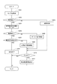
本実施形態における回転情報演算処理を図17に示すフローチャートに基づいて説明する。ここでは、第1センサ部61における処理として説明するが、第2センサ部62においても同様の処理が行われる。フローチャートの説明に係り、ステップS101の「ステップ」を省略し、単に記号「S」と記す。他のステップについても同様である。
The rotation information calculation processing in this embodiment will be described based on the flowchart shown in FIG. Here, although described as processing in the
最初のS101では、第1センサ部61は、電動パワーステアリング装置108が動作中か否かを判断する。図中、電動パワーステアリング装置を「EPS」と記載する。例えば、第1マイコン51からのクロック信号や指令信号等が所定期間以上に亘って送信されない場合、電動パワーステアリング装置108が停止していると判断できる。電動パワーステアリング装置108が停止していると判断された場合(S101:NO)、S104へ移行する。電動パワーステアリング装置108が動作中であると判断された場合(S101:YES)、S102へ移行する。
In the first S101, the
S102では、第1センサ部61は、回転角θmおよび回転回数TCを演算する。
S103では、第1センサ部61は、第1マイコン51からの指令に応じ、出力信号を送信する。第1マイコン51では、取得した出力信号に含まれる信号を用い、回転角θmおよび舵角θs等の演算を行う。
In S102, the
In S <b> 103, the
電動パワーステアリング装置108が停止していると判断された場合(S101:NO)に移行するS104では、モータ部10が停止中か否かを判断する。モータ部10が停止中か否かは、例えばモータ部10の回転速度が判定閾値より小さい場合、モータ部10が停止中であるみなす。また例えば、回転角θmが演算されていない場合、または、センサ素子からの出力値の変化量(例えば前回値との差分値や微分値等)が判定閾値より小さい場合、モータ部10が停止中であるとみなす。また例えば、モータ部10の1回転を3以上の領域に分けてカウントする場合、同一のカウント値が所定期間に亘って継続されているとき、モータ部10が停止中であるとみなす。モータ部10が動作中であると判断された場合(S104:NO)、S105へ移行する。モータ部10が停止中であると判断された場合(S104:YES)、S106へ移行する。
When it is determined that the electric
S105では、回転回数演算部615は、第1の頻度f1にて回転回数TCを演算する。第1の頻度f1は、モータ部10の駆動時に読み飛ばしが生じない程度に設定される。なお、S105に移行した場合、所定期間は、第1の頻度f1にて回転回数TCを演算するようにしてもよい。
S106では、回転回数演算部615は、第2の頻度f2にて回転回数TCを演算する。第2の頻度f2は、第1の頻度f1より低いものとする。すなわちf1>f2である。モータ部10の停止中は、回転回数TCは変わらないので、回転回数TCの演算頻度を下げ、例えば間欠動作とすることで、消費電力を抑えることができる。
In S105, the rotation
In S106, the rotation
また、電動パワーステアリング装置108の動作中における回転回数TCの演算頻度を、第1の頻度f1以上とすることで、読み飛ばしを防ぐことができる。また、電動パワーステアリング装置108の動作中は、回転角θmが第1マイコン51へ送信されているので、第1マイコン51にて、回転角θmに基づいて回転回数TCを演算可能である。そのため、電動パワーステアリング装置108の動作中における回転回数TCの演算頻度は、第1の頻度f1より小さくてもよい。
Moreover, skipping of reading can be prevented by setting the calculation frequency of the number of rotations TC during the operation of the electric
S105またはS106に続いて移行するS107では、第1センサ部61は、回転回数TCをセンサ内部にて保持しておく。なお、全ての演算値を保持しておく必要はなく、最新の値が保持されていればよい。回転回数TCに係る回転回数信号は、電動パワーステアリング装置108の再始動時に、回転角θmに係る回転角信号とともに第1マイコン51に送信される。
In S107, which proceeds from S105 or S106, the
本実施形態では、モータ部10が動作中か否かに応じ、回転回数演算部615、625における回転回数TCの更新頻度を変更する。詳細には、モータ部10が停止中である場合、動作中と比較し、回転回数TCの更新頻度を下げる。これにより、特に電動パワーステアリング装置108の停止中における消費電力を低減することができる。
In the present embodiment, the update frequency of the rotation number TC in the rotation
また本実施形態では、センサ部61、62には、モータ部10を含むシステムである電動パワーステアリング装置108の停止中においても、バッテリ39から電力が供給される。これにより、電動パワーステアリング装置108の停止中においても、回転検出装置1への給電が継続され、回転回数TCの演算を継続することができる。電動パワーステアリング装置108の停止中も回転回数TCの演算を継続することで、電動パワーステアリング装置108が再始動された際にも、ステアリングホイール101の中立位置の再学習をすることなく、舵角θsを適切に演算することができる。
また、上記実施形態と同様の効果を奏する。
In the present embodiment, electric power is supplied from the
In addition, the same effects as those of the above embodiment can be obtained.
(第6実施形態)
本発明の第6実施形態を図18〜図20に示す。
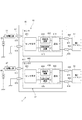
図18に示すように、本実施形態の回転検出装置5は、第1センサ部561、第2センサ部562、第1マイコン51および第2マイコン52を備える。第1センサ部561は、センサ素子601、607および回路部613を有し、1つのチップ641により構成される。第2センサ部562は、センサ素子602、608および回路部623を有し、1つのチップ642により構成される。
(Sixth embodiment)
A sixth embodiment of the present invention is shown in FIGS.
As shown in FIG. 18, the
センサ端子68は、パッケージ65に設けられる。センサ端子68には、電源端子675、677、681、682、グランド端子676、678、通信端子685、686が含まれる。
電源端子675は、定電圧源371を経由して第1バッテリ39と接続される。
電源端子681は、定電圧源372を経由して第1バッテリ39に接続される。定電圧源372は、電源リレー32、逆接保護リレー33およびダイオード373を経由して、第1バッテリ39と接続される。また、定電圧源372は、スイッチ379およびダイオード374を経由して第1バッテリ39と接続される。ダイオード373、374は、第1バッテリ39側から定電圧源372側への通電を許容し、逆向きの通電を禁止する向きに配置される。
The
The
The
電源端子677は、定電圧源471を経由して第2バッテリ49に接続される。
電源端子682は、定電圧源472を経由して第2バッテリ49に接続される。定電圧源472は、電源リレー42、43およびダイオード473を経由して、第2バッテリ49と接続される。また、定電圧源472は、スイッチ479およびダイオード474を経由して第1バッテリ39と接続される。ダイオード473、484は、第2バッテリ49側から定電圧源472側への通電を許容し、逆向きの通電を禁止する向きに配置される。
スイッチ379、479は、IGと同期してオンオフされる。スイッチ379、479の一方がIGそのものであってもよい。
The
The
The
定電圧源371、372、471、472は、上記実施形態の定電圧源37、47と同様、センサ部61、62を駆動できる程度(例えば数mA程度)の電力消費量が小さいレギュレータ等であって、駆動装置800の停止中にもセンサパッケージ65に電力供給可能なものである。定電圧源371、372、471、472は、同様のものであってもよいし、異なっていてもよい。図中、定電圧源371、372、471、472を、「定電圧源1〜4」とした。また、図18では、電源リレーおよび逆接保護リレーを1つのブロックで記載した。
The
本実施形態では、第1センサ部561は、通信端子685および通信線695を経由して第1マイコン51と接続され、第2センサ部562は、通信端子686および通信線696を経由して第2マイコン52と接続される。換言すると、本実施形態では、通信端子685を、マイコン側からの指令の送受信と、センサ部側からの出力信号の送受信とに共用している。
なお、第4実施形態等においても、1つのセンサ部に対し、複数の定電圧源および電源端子を設けるようにしてもよい。また、指令端子および出力端子に替えて通信端子を設けるようにしてもよい。
In the present embodiment, the
In the fourth embodiment, etc., a plurality of constant voltage sources and power supply terminals may be provided for one sensor unit. Further, a communication terminal may be provided instead of the command terminal and the output terminal.
第1センサ部561の回路部613は、第4実施形態の回路部611の各構成に加え、センサ素子607、および、回転角演算部616を有する。換言すると、回路部613は、第5実施形態の回路部612における回転回数演算部617が省略されている。また、回転情報演算回路956は、第5実施形態の回転情報演算回路952から回転回数演算部617が省略されている、ともいえる。
The
第2センサ部562の回路部623は、第4実施形態の回路部612の各構成に加え、センサ素子608、および、回転角演算部626を有する。換言すると、回路部623は、第5実施形態の回路部622における回転回数演算部627が省略されている。また、回転情報演算回路957は、第5実施形態の回転情報演算回路954から回転回数演算部627が省略されている、ともいえる。
The
以下、第1センサ部561のセンサ素子601を「p1」とし、センサ素子601の検出値に基づく値に添え字「p1」を付し、センサ素子607を「q1」とし、センサ素子607の検出値に基づく値に添え字「q1」を付す。また、第2センサ部562のセンサ素子602を「p2」とし、センサ素子602の検出値に基づく値に添え字「p2」を付し、センサ素子608を「q2」とし、センサ素子608の検出値に基づく値に添え字「q2」を付す。また、第1センサ部561にて検出された値には添え字「1」を付し、第2センサ部562にて検出された値には添え字「2」を付す。なお、演算に用いたセンサ素子や回転検出部を区別する必要がない場合、添え字を適宜省略する。
Hereinafter, the
センサ素子601、602、607、608は、同じ種類のものであってもよいし、異なる種類のものであってもよい。例えば、センサ素子601、607をGMR素子とし、センサ素子602、608をホール素子とする、といった具合に、同一センサ部の2つのセンサ素子に異なる種類のものを用いることで、検出手段の異なる情報による冗長の堅牢性を高めることができる。
The
本実施形態では、第1センサ部561のセンサ素子601、回転回数演算部615および自己診断部618には、電源端子675を経由して、第1バッテリ39から常時給電される。また、センサ素子607、回転角演算部614、616および通信部619は、リレー32、33またはスイッチ379がオンされているとき、第1バッテリ39から給電され、リレー32、33およびスイッチ379がオフされているとき、給電されず、動作を停止する。
また、第2センサ部562のセンサ素子602、回転回数演算部625および自己診断部628には、電源端子677を経由して、第2バッテリ49から常時給電される。また、センサ素子608、回転角演算部624、626および通信部629は、リレー42、43またはスイッチ479がオンされているとき、第2バッテリ49から給電され、リレー42、43およびスイッチ479がオフされているとき、給電されず、動作を停止する。
In the present embodiment, power is constantly supplied from the
In addition, the
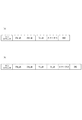
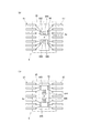
本実施形態の出力信号を説明する通信フレームを図19に基づいて説明する。
図19(a)に示すように、1回の通信における出力信号の通信フレームには、ランカウンタ信号、回転角θm_pkに係る信号、回転角θm_qkに係る信号、回転回数TC_pkに係る信号、ステータス信号、および、CRC信号が含まれる。ビット数や信号順等は、適宜設定可能である。
また、第4実施形態のように、センサ素子607に基づいて回転回数TC_p1が演算され、センサ素子608に基づいて回転回数TC_q2が演算される場合、図19(b)に示すように、1回の通信における出力信号の通信フレームには、ランカウンタ信号、回転角θm_pkに係る信号、回転角θm_qkに係る信号、回転回数TC_pkに係る信号、回転回数TC_qkに係る信号、ステータス信号、および、CRC信号が含まれる。なお、pまたはqに続く添え字「k」は、第1センサ部561からの出力信号の場合は「1」、第2センサ部562からの出力信号の場合は「2」となる。
A communication frame for explaining an output signal of the present embodiment will be described with reference to FIG.
As shown in FIG. 19A, a communication frame of an output signal in one communication includes a run counter signal, a signal related to the rotation angle θm_pk, a signal related to the rotation angle θm_qk, a signal related to the number of rotations TC_pk, and a status signal. And CRC signals are included. The number of bits, signal order, etc. can be set as appropriate.
Further, when the rotation number TC_p1 is calculated based on the
図18に戻り、本実施形態では、マイコン51、52は、情報を相互に送受信可能に構成される。したがって、マイコン51、52は、それぞれにおいて、4つのセンサ素子601、602、607、608の検出値に基づく回転角θmに係る情報、および、2つのセンサ素子601、602の検出値に基づく回転回数TCに係る情報を利用可能である。詳細には、マイコン51、52では、センサ素子601の検出値に基づく回転角θm_p1、回転回数TC_p1、センサ素子607の検出値に基づく回転角θm_q1、センサ素子602の検出値に基づく回転角θm_p2、回転回数TC_p2、センサ素子608の検出値に基づく回転角θ、_q2を利用可能である。
Returning to FIG. 18, in this embodiment, the
第1マイコン51では、第1センサ部561から直接的に取得される出力信号に含まれる回転角および回転回数に係る情報、および、第2マイコン52から通信にて取得される第2センサ部652からの出力信号に含まれる回転角および回転回数に係る情報に基づき、異常判定を行う。
第2マイコン52では、第2センサ部562から直接的に取得される出力信号に含まれる回転角および回転回数に係る情報、および、第1マイコン51から通信にて取得される第1センサ部651からの出力信号に含まれる回転角および回転回数に係る情報に基づき、異常判定を行う。
In the
In the
異常検出処理を図20のフローチャートに基づいて説明する。この処理は、例えばIGがオンされている期間に、所定の周期で実施される。マイコン51、52における異常判定処理は略同様であるので、以下、第1マイコン51での処理を中心に説明する。なお。第2マイコン52では、第1センサ部561の出力信号に替えて、第2センサ部562の出力信号を用い、マイコン間通信にて取得される信号として、第1マイコン51から取得される第1センサ部561のからの出力信号を用いる。
The abnormality detection process will be described based on the flowchart of FIG. This process is performed at a predetermined cycle, for example, during a period in which the IG is turned on. Since the abnormality determination process in the
最初のS201では、第1マイコン51は、第1センサ部561から出力信号を取得する。また、第1マイコン51は、第2センサ部562からの出力信号を第2マイコン52からマイコン間通信にて取得する。
S202では、第1マイコン51は、対応して設けられる第1センサ部561の異常を検出する。第1マイコン51は、以下の(i)〜(iv)の少なくとも1つにより、第1センサ部561の異常検出を行う。また、異常が検出された場合、(v)により異常箇所を特定する。
In the first S201, the
In S202, the
(i)ランカウンタ信号に基づき、ランカウンタが更新されていない場合、通信途絶異常が生じていると判定する。
(ii)ステータス信号に基づき、第1センサ部651の自己診断機能による異常検出結果に応じた異常判定を行う。
(iii)CRC信号に基づき、出力信号のデータ破損の有無を判定する。
(iv)回転角θm_p1と回転回数TC_p1との比較による異常判定を行う。回転角θm_p1と回転回数TC_p1とを比較する場合、比較可能なように適宜換算する。例えば、回転回数θm_p1の変化量の積算値に基づき、回転回数TC_p1と比較可能な回転回数換算値を演算可能である。なお、換算値を比較することは、「回転角信号と回転回数信号との比較」の概念に含まれるものとする。
本実施形態では、回転角θm_p1、θm_q1の比較による異常判定結果は、ステータス信号に含まれるものとするが、第1マイコン51側にて回転角θm_p1、θm_q1の比較を行ってもよい。
(I) If the run counter is not updated based on the run counter signal, it is determined that a communication interruption abnormality has occurred.
(Ii) Based on the status signal, the abnormality determination is performed according to the abnormality detection result by the self-diagnosis function of the first sensor unit 651.
(Iii) Based on the CRC signal, the presence or absence of data corruption in the output signal is determined.
(Iv) An abnormality is determined by comparing the rotation angle θm_p1 with the number of rotations TC_p1. When the rotation angle θm_p1 is compared with the number of rotations TC_p1, it is appropriately converted so that the comparison is possible. For example, based on the integrated value of the amount of change in the rotation number θm_p1, a rotation number conversion value that can be compared with the rotation number TC_p1 can be calculated. Note that the comparison of the converted values is included in the concept of “comparison between rotation angle signal and rotation frequency signal”.
In this embodiment, the abnormality determination result by comparing the rotation angles θm_p1 and θm_q1 is included in the status signal. However, the rotation angles θm_p1 and θm_q1 may be compared on the
異常が検出された場合、(v)第2マイコン51からマイコン間通信にて取得される第2センサ部562からの出力信号に基づく値との比較により、異常箇所を特定する。異常箇所が特定された場合、異常履歴情報を図示しない記憶部等に記憶させ、異常履歴を保持する。
When an abnormality is detected, (v) the abnormal part is identified by comparison with a value based on an output signal from the
第1センサ部561の異常が検出された場合(S202:YES)、S204へ移行する。第1センサ部561の異常が検出されなかった場合(S202:NO)、S203へ移行し、第1マイコン51は、第1センサ部561から取得される値に基づき、通常制御によりモータ部10の駆動を制御する。ここで制御に用いられる値は、スイッチ379、479のオン継続中に異常履歴のないセンサ素子の検出値に基づく値とする。また、スイッチ379、479のオンオフによらず、正常復帰したセンサ素子の検出値を制御に用いてもよい。
S204では、第1マイコン51は、異常検出前の値をホールドする。
When abnormality of the
In S204, the
S205では、第1マイコン51は、第1センサ部561の異常が確定したか否かを判断する。本実施形態では、所定時間に亘って異常が継続した場合、異常を確定させる。異常検出中であって、第1センサ部561の異常が確定されていない場合(S205:NO)、S206へ移行する。第1センサ部561の異常が確定された場合(S205:YES)、S207へ移行する。
S206では、第1マイコン51は、異常検出前のホールド値を用いてモータ部10の駆動制御を継続する。また、異常箇所が特定されている場合、ホールド値に替えて、正常値を用いて制御を行ってもよい。
In S205, the
In S206, the
S207では、第1マイコン51は、異常箇所を特定できたか否かを判断する。異常箇所を特定できなかったと判断された場合(S204:NO)、S209へ移行する。異常箇所を特定できた場合(S204:YES)、S208へ移行する。
In S207, the
S208では、第1マイコン51は、正常値を用いた制御を継続する。ここでいう「正常値」とは、異常検出履歴のないセンサ素子の検出値である。また、一時的に異常が検出されたものの異常確定されずに正常復帰したセンサ素子の検出値を正常値としてもよい。
なお、第1センサ部561の異常が確定した場合、S207およびS208の処理を省略し、異常箇所が特定可能な場合であっても、第1系統901を用いた制御を停止してもよい。
S209では、第1マイコン51は、第1系統901を用いた制御を停止する。なお、第2センサ部562が正常であれば、第2マイコン52により、第2系統902を用いた制御が継続される。
In S208, the
In addition, when abnormality of the
In S209, the
S203、S206またはS208に続いて移行するS210では、第1マイコン51は、IGがオフされたか否かを判断する。本実施形態では、マイコン51、52は、IGオフ後もしばらくの間は演算を継続可能であり、所定の終了処理等が終わった後にオフされるものとする。IGがオフされていないと判断された場合(S210:NO)、S211の処理を行わない。IGがオフされたと判断された場合(S210:YES)、S211へ移行し、異常履歴情報を消去する。これにより、IGが再度オンされた場合、一時的に異常が検出され、正常復帰したセンサ素子は、正常なセンサ素子として扱われる。なお、異常履歴情報が記憶されるメモリが揮発性メモリであれば、S210、S211の処理は省略可能である。
In S210, which proceeds from S203, S206, or S208, the
本実施形態では、出力信号に含まれるランカウンタ信号、ステータス信号およびCRC信号等に基づき、出力信号の異常の有無を判定可能である。
また、回転角θm_p1、θm_q1、および、回転回数TC_p1を比較することによる異常監視が可能である。これらの値は、同一の通信フレームにて出力される値であるので、タイムラグによる誤差が小さい。なお、回転角θm_p1および回転回数TC_p1は同一のセンサ素子601の検出値に基づく値であるので、例えば回転角θm_p1に基づく回転回数換算値と回転回数TC_p1とが異なる場合、回転角θm_q1に基づく回転回数換算値との比較による異常特定が可能である。
In the present embodiment, it is possible to determine whether the output signal is abnormal based on a run counter signal, a status signal, a CRC signal, and the like included in the output signal.
Further, abnormality monitoring is possible by comparing the rotation angles θm_p1, θm_q1, and the number of rotations TC_p1. Since these values are values output in the same communication frame, an error due to a time lag is small. Since the rotation angle θm_p1 and the rotation number TC_p1 are values based on the detection value of the
さらにまた、本実施形態では、マイコン51、52は、マイコン間通信により、2つのセンサ部561、562の検出値を取得可能である。本実施形態では、センサ部561、562には、計4つのセンサ素子が設けられている。センサ素子が3つ以上であるので、多数決の理論等により、異常箇所を特定することができる。
Furthermore, in this embodiment, the
本実施形態では、出力信号には、ランカウンタ信号、ステータス信号、および、誤り検出信号であるCRC信号が含まれる。ステータス信号は、自己診断部618、628による診断結果に基づく信号である。
マイコン51、52は、ランカウンタ信号、ステータス信号およびCRC信号に基づき、センサ部561、562の異常を監視する。これにより、マイコン51、52は、センサ部561、562の異常を適切に監視することができる。
In the present embodiment, the output signal includes a run counter signal, a status signal, and a CRC signal that is an error detection signal. The status signal is a signal based on a diagnosis result by the self-
The
マイコン51、52は、回転角信号と回転回数信号との比較により、センサ部561、562の異常を監視する。本実施形態では、回転角信号および回転回数信号は、同一フレームにて出力されているので、同一の出力信号に含まれる回転角信号と回転回数信号とを比較することで、タイムラグの少ない情報に基づいて適切に異常を監視することができる。
The
マイコン51は、センサ部561の異常が検出されてから所定時間に亘って異常が継続した場合、センサ部561の異常を確定する。マイコン52は、センサ部562の異常が検出されてから所定時間に亘って異常が継続した場合、センサ部562の異常を確定する。これにより誤判定を避け、適切に異常を確定することができる。
マイコン51、52は、正常時における出力信号に基づく値をホールドしておき、異常検出から異常確定までの間、正常時にホールドされた値を用いて演算を継続する。これにより、異常が生じている値を用いずに演算を継続することができる。
The
The
第1センサ部561の異常が確定された場合、第1センサ部561から出力信号を取得する第1マイコン51での演算を停止する。また、第2センサ部562の異常が確定された場合、第2センサ部562からの出力信号を取得する第2マイコン52での演算を停止する。これにより、異常である値を用いた演算を避けることができる。
マイコン51、52は、異常箇所が特定できた場合、正常な信号を用いて演算を継続してもよい。これにより、異常箇所に応じ、適切に演算を継続することができる。
When abnormality of the
When the abnormal part can be identified, the
マイコン51、52は、センサ部561、562の異常が検出された場合、スイッチ379、479がオンされている間、異常検出履歴を保持する。イグニッションスイッチがオフされた後にオンされた場合、異常検出履歴が消去される。これにより、イグニッションスイッチのオン継続中は、異常検出履歴がある情報を用いずに演算を継続することができる。
When the abnormalities of the
1つの制御部である第1マイコン51に対して出力信号を送信する第1センサ部561を自系統センサ部、他の制御部である第2マイコンに対して出力信号を送信する第2センサ部562を他系統センサ部とする。
第1マイコン51は、第1センサ部561から取得される出力信号に含まれる値と、第2マイコン52から通信にて取得される第2センサ部562に係る出力信号に含まれる値とに基づき、異常箇所を特定する。
第2センサ部562を自系統センサ部、第1センサ部561を他系統センサ部とすると、第2マイコン52では、第2センサ部562から取得される出力信号に含まれる値と、第1マイコン51から通信にて取得される第1センサ部561に係る出力信号に含まれる値とに基づき、異常箇所と特定する。
これにより、異常箇所を適切に特定することができる。
A
The
When the
Thereby, an abnormal location can be specified appropriately.
(第7実施形態)
本発明の第7実施形態を図21に示す。
図21に示すように、本実施形態の回転検出装置6は、2つのセンサ部561、562に対し、1つのマイコン53が設けられる。図21では、センサ部として、第7実施形態のセンサ部561、562を用いる例を示しているが、他の実施形態のセンサ部を用いてもよい。第8実施形態についても同様である。
このように構成しても、上記実施形態と同様の効果を奏する。
本実施形態では、マイコン53が「制御部」に対応する。
(Seventh embodiment)
A seventh embodiment of the present invention is shown in FIG.
As shown in FIG. 21, in the
Even if comprised in this way, there exists an effect similar to the said embodiment.
In the present embodiment, the
(第8実施形態)
本発明の第8実施形態を図22に示す。
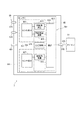
図22に示すように、本実施形態のコントローラ部20には、外部装置900からの情報が入力される。本実施形態の外部装置900は、ステアリングシャフト102の回転角度を検出するステアリングセンサである。また、外部装置900は、舵角θsを演算可能な他のセンサ(例えば舵角検出可能なトルクセンサ)等であってもよい。
(Eighth embodiment)
FIG. 22 shows an eighth embodiment of the present invention.
As shown in FIG. 22, information from the
マイコン51、52は、第1センサ部61の検出値に基づいて演算される舵角θs1、第2センサ部62の検出値に基づいて演算される舵角θs2、および、外部装置900の検出値に基づいて演算される舵角θs3を比較することで、異常検出および異常箇所の特定を行う。本実施形態では、センサ部61、62の異常検出および異常箇所の特定に、検出手段の異なる外部装置900の情報を用いているので、冗長の堅牢性を高めることができる。
このように構成しても上記実施形態と同様の効果を奏する。
The
Even if comprised in this way, there exists an effect similar to the said embodiment.
(第9実施形態)
本発明の第9実施形態を図23および図24に示す。
図23に示すように、本実施形態の回転検出装置7は、1つのセンサ部561、および、1つのマイコン51を備える。センサ端子69は、端子675、674、677、678が省略されている点を除き、センサ端子67と同様である。図23では、センサ部として第6実施形態のセンサ部561を用いる例を示しているが、第6実施形態以外のセンサ部を用いてもよい。
本実施形態の異常検出処理を図24のフローチャートに基づいて説明する。この処理は、例えばIGがオンされている期間に、所定の周期で実施される。
(Ninth embodiment)
A ninth embodiment of the present invention is shown in FIGS.
As shown in FIG. 23, the
The abnormality detection process of this embodiment will be described based on the flowchart of FIG. This process is performed at a predetermined cycle, for example, during a period in which the IG is turned on.
最初のS301では、マイコン51は、センサ部561から出力信号を取得する。
S302では、マイコン51は、センサ部561の異常を検出する。ここでは、第6実施形態に示した(i)〜(iv)により異常検出を行う。なお、本実施形態では、センサ素子601、607が2つであるので、異常箇所を特定することはできない。
センサ部561の異常が検出された場合(S302:YES)、S304へ移行する。センサ部561の異常が検出されなかった場合(S302:YES)、S303へ移行する。
S303の処理は、図20中のS203の処理と同様である。
In the first S301, the
In S <b> 302, the
If an abnormality of the
The process of S303 is the same as the process of S203 in FIG.
センサ部561の異常が検出された場合(S302:YES)に移行するS304では、マイコン51は、異常検出前の値をホールドする。
S305では、マイコン51は、センサ部561の異常が確定したか否かを判断する。本実施形態では、所定期間に亘って異常が継続した場合、異常を確定される。センサ部561の異常が確定された場合(S305:YES)、S307へ移行する。異常検出中であって、センサ部561の異常が確定されていない場合(S305:NO)、S306へ移行する。
In S304, when the abnormality of the
In S305, the
S306では、マイコン51は、異常検出前のホールド値を用いてモータ部10の駆動制御を継続する。
S307では、マイコン51は、モータ部10の駆動制御を停止する。
本実施形態のように、センサ部およびマイコンが1組であっても、上記実施形態と同様の効果を奏する。
In S306, the
In S307, the
Even if the sensor unit and the microcomputer are one set as in the present embodiment, the same effects as those of the above embodiment can be obtained.
(第10実施形態)
本発明の第10実施形態を図25に示す。図25は、図8に対応する模式図である。第10実施形態〜第12実施形態では、マイコンの記載を省略する。
上記実施形態の回転検出装置1等では、センサ素子601および回路部610が1つのチップ641で構成され、センサ素子602および回路部620が1つのチップ642で構成される。
(10th Embodiment)
A tenth embodiment of the present invention is shown in FIG. FIG. 25 is a schematic diagram corresponding to FIG. In the tenth to twelfth embodiments, the description of the microcomputer is omitted.
In the
本実施形態の回転検出装置8では、回路部610を含むチップ643と、センサ素子601を含むチップ644とが別チップに分けられている。また、回路部620を含むチップ645と、センサ素子602を含むチップ646とが別チップに分けられている。図25では、各チップに含まれるセンサ素子および回路部の記載を省略している。また、回路部610に替えて、回路部611、612としてもよいし、回路部620に替えて、回路部621、622としてもよい。また、第2実施形態等のように、センサ素子を各2つとしてもよい。
In the
図25(a)に示すように、回路部610を含むチップ643は、リードフレーム66上に設けられる。センサ素子601を含むチップ644は、チップ643の上面に設けられる。ここで、チップの「上面」とは、チップのリードフレーム66と反対側の面を意味する。
また、回路部620を含むチップ645は、リードフレーム66上に設けられる。センサ素子602を含むチップ646は、チップ645の上面に設けられる。
センサ素子を含むチップ644、646を、回路部を含むチップ643、645の上に配置することで、リードフレーム66における実装面積を小さくすることができ、回転検出装置5を小型化することができる。
As shown in FIG. 25A, the
The
By disposing the
また、図25(b)に示すように、センサ素子を含むチップ644、646を回転中心線Ac側に配置し、回路部を含むチップ643、645を外側に配置してもよい。これにより、センサ素子601、602を回転中心線Acに近づけて配置できるので、検出精度が高まる。また、チップ644、646は、回転中心線Acに対して点対称となるように配置される。
なお、制御構成等については、いずれの実施形態のものと組み合わせてもよい。
このように構成しても、上記実施形態と同様の効果を奏する。
Further, as shown in FIG. 25B,
In addition, about a control structure etc., you may combine with the thing of any embodiment.
Even if comprised in this way, there exists an effect similar to the said embodiment.
(第11実施形態)
本発明の第11実施形態を図26〜図28に示す。
上記実施形態では、2つのセンサ部61、62は、1つのパッケージ65に設けられる。本実施形態の回転検出装置9では、第1センサ部61が第1パッケージ661に設けられ、第2センサ部62が第2パッケージ662に設けられる。すなわち本実施形態では、パッケージ661、662が、センサ部61、62毎に設けられている。センサ部の構成等は、第1実施形態以外の実施形態で説明したものとしてもよい。第12実施形態についても同様である。
(Eleventh embodiment)
An eleventh embodiment of the present invention is shown in FIGS.
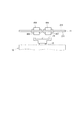
In the above embodiment, the two
図26および図27に示すように、第1パッケージ661が第1基板21の第1面211に実装され、第2パッケージ662が第1基板21の第2面212に実装される。パッケージ661、662をセンサ部61、62とし、第1基板21の両面に実装することで、第1基板21における回転検出装置9の実装面積を低減することができる。また、各センサ部61、62のセンサ素子601、602は、共に回転中心線Ac上に配置される。これにより、検出精度を高めることができる。
また、パッケージ661、662は、図28(a)のように、第1基板21の第1面211に実装してもよいし、図28(b)のように、第1基板21の第2面212に実装してもよい。
As shown in FIGS. 26 and 27, the
The
本実施形態では、センサ部61、62が複数組設けられ、センサ部61、62ごとにパッケージ661、662が設けられる。センサ部61、62ごとにパッケージ661、662を設けることで、回転検出装置1の配置の自由度が高まる。また、パッケージ故障による複数系統の同時故障を防ぐことができ、一方のパッケージに異常が生じた場合であっても、他方のパッケージに含まれる各構成により、回転角θmおよび回転回数TCの演算を継続可能である。
また、上記実施形態と同様の効果を奏する。
In the present embodiment, a plurality of sets of
In addition, the same effects as those of the above embodiment can be obtained.
(第12実施形態)
本発明の第12実施形態を図29に示す。図29では、ばね端子等、一部の部品の記載を省略した。
上記実施形態では、第1基板21にSW素子301〜306、401〜406、コンデンサ36、46、および、回転検出装置1等が実装され、第2基板22にマイコン51、52、および、集積回路56、57等が実装される。
(Twelfth embodiment)
A twelfth embodiment of the present invention is shown in FIG. In FIG. 29, description of some components, such as a spring terminal, was abbreviate | omitted.
In the above embodiment, the
図29に示すように、本実施形態では、1枚の基板23にSW素子301〜306、コンデンサ36、46、集積回路56、57、および、回転検出装置9が実装される。回転検出装置9には、センサ部61、62、および、マイコン51、52が含まれる。
SW素子301〜306、401〜406、集積回路56、57、および、パッケージ661等が、基板23のモータ部10側の面である第1面231に実装される。また、コンデンサ36、46、マイコン51、52、および、パッケージ662等が基板23のモータ部10と反対側の面である第2面232に実装される。
As shown in FIG. 29, in this embodiment, the
The
図30では、センサ部61、62毎にパッケージ661、662が設けられ、基板23の両面に実装される例を示しているが、パッケージ661、662をいずれか一方の面に実装してもよい。また、センサ部61、62を1パッケージとしてもよい。センサ部61、62を1パッケージとする場合、回転検出装置6を基板23の第1面231に実装することが、検出精度の面から望ましい。
1枚の基板23に駆動装置800の制御に係る部品を実装することで、部品点数を低減できる。また、複数の基板を軸方向に積層して設ける場合と比較し、軸方向における体格を小型化することができる。
このように構成しても、上記実施形態と同様の効果を奏する。
FIG. 30 shows an example in which packages 661 and 662 are provided for each of the
By mounting components related to control of the
Even if comprised in this way, there exists an effect similar to the said embodiment.
(他の実施形態)
上記実施形態では、回転検出装置には、2つのセンサ部が設けられる。他の実施形態では、センサ部の数は、1つであってもよいし、3つ以上であってもよい。
上記実施形態では、回転情報演算回路は、1つのセンサ部に1組または2組設けられる。他の実施形態では、1つのセンサ部に回転情報演算回路を3組以上設けてもよい。
上記実施形態では、1つの回路部に対し、1つまたは2つのセンサ素子が設けられる。他の実施形態では、1つの回路部に対し、3つ以上のセンサ素子を設けてもよい。
(Other embodiments)
In the above embodiment, the rotation detection device is provided with two sensor units. In other embodiments, the number of sensor units may be one, or may be three or more.
In the above embodiment, one or two rotation information calculation circuits are provided in one sensor unit. In another embodiment, three or more sets of rotation information calculation circuits may be provided in one sensor unit.
In the above embodiment, one or two sensor elements are provided for one circuit unit. In another embodiment, three or more sensor elements may be provided for one circuit unit.
上記実施形態では、制御部とセンサ部との間での通信方式として、SPI通信を例示した。他の実施形態では、制御部とセンサ部との間での通信方式は、SPI通信に限らず、SENT(Single Edge Nibble Transmission)通信等、回転角信号および回転回数信号を一連の信号に含めることができれば、どのような方式であってもよい。
第5実施形態では、モータが停止中か否かに応じ、回転回数の演算頻度を変更する。他の実施形態では、モータや電動パワーステアリング装置の状態によらず、回転回数の演算を所定の頻度で行うようにしてもよい。
In the above embodiment, SPI communication is exemplified as a communication method between the control unit and the sensor unit. In another embodiment, the communication method between the control unit and the sensor unit is not limited to SPI communication, but includes a rotation angle signal and a rotation frequency signal such as SENT (Single Edge Nibble Transmission) communication in a series of signals. As long as it is possible, any method may be used.
In the fifth embodiment, the calculation frequency of the number of rotations is changed according to whether or not the motor is stopped. In another embodiment, the number of rotations may be calculated at a predetermined frequency regardless of the state of the motor or the electric power steering device.
上記実施形態では、検出対象は、モータ部である。他の実施形態では、検出対象は、モータに限らず、回転の検出を要するモータ以外の装置であってもよい。
上記実施形態では、モータ部は三相ブラシレスモータである。他の実施形態では、モータ部は、三相ブラシレスモータに限らず、どのようなモータであってもよい。また、モータ部は、モータ(電動機)に限らず、発電機であってもよいし、電動機および発電機の機能を併せ持つ所謂モータジェネレータであってもよい。
In the above embodiment, the detection target is a motor unit. In another embodiment, the detection target is not limited to a motor, but may be a device other than a motor that requires rotation detection.
In the above embodiment, the motor unit is a three-phase brushless motor. In other embodiments, the motor unit is not limited to a three-phase brushless motor, and may be any motor. The motor unit is not limited to a motor (electric motor) but may be a generator, or a so-called motor generator having both functions of an electric motor and a generator.
上記第1実施形態等では、第1基板に駆動部品および回転検出装置のセンサパッケージが実装され、第2基板に制御部品が実装される。他の実施形態では、第1基板に制御部品の少なくとも一部を実装したり、第2基板に駆動部品の少なくとも一部を実装したりしてもよい。例えば、第1基板に第1系統に係る駆動部品および制御部品を実装し、第2基板に第2系統に係る駆動部品および制御部品を実装するようにしてもよい。系統毎に基板を分けることで、一方の基板に異常が生じた場合にも、他方の基板に実装される駆動部品および制御部品を用いることで、電動パワーステアリング装置の駆動を継続することができる。また、複数の基板が設けられる場合、基板の間にヒートシンクを設け、放熱が必要な部品の少なくとも一部をヒートシンクに放熱させるようにしてもよい。 In the first embodiment and the like, the drive component and the sensor package of the rotation detection device are mounted on the first substrate, and the control component is mounted on the second substrate. In another embodiment, at least a part of the control component may be mounted on the first substrate, or at least a part of the drive component may be mounted on the second substrate. For example, the driving component and the control component according to the first system may be mounted on the first substrate, and the driving component and the control component according to the second system may be mounted on the second substrate. By dividing the board for each system, even when an abnormality occurs on one board, the drive of the electric power steering device can be continued by using the drive parts and control parts mounted on the other board. . In the case where a plurality of substrates are provided, a heat sink may be provided between the substrates, and at least a part of components that need to be radiated may be radiated to the heat sink.
上記実施形態では、駆動装置は、電動パワーステアリング装置に適用される。他の実施形態では、駆動装置を電動パワーステアリング装置以外の装置に適用してもよい。
以上、本発明は、上記実施形態になんら限定されるものではなく、発明の趣旨を逸脱しない範囲において種々の形態で実施可能である。
In the above embodiment, the drive device is applied to an electric power steering device. In another embodiment, the drive device may be applied to a device other than the electric power steering device.
As mentioned above, this invention is not limited to the said embodiment at all, In the range which does not deviate from the meaning of invention, it can implement with a various form.
1〜9・・・回転検出装置
10・・・モータ部(検出対象)
51、52、53・・・マイコン(制御部)
61、62、261、262、461、462、561、562・・・センサ部
601〜608・・・センサ素子
610〜613、620〜623・・・回路部
614、624、616、626・・・回転角演算部
615、625、617、627・・・回転回数演算部
619、629・・・通信部
1 to 9: Rotation detection device 10: Motor unit (detection target)
51, 52, 53... Microcomputer (control unit)
61, 62, 261, 262, 461, 462, 561, 562...
Claims (22)
前記センサ部から前記出力信号を取得し、前記出力信号に基づく演算を行う制御部(51、52、53)と、
を備え、
前記回路部は、
前記センサ素子の検出値に基づいて前記検出対象の回転角を演算する回転角演算部(614、624、616、626)、
前記センサ素子の検出値に基づいて前記検出対象の回転回数をカウントする回転回数演算部(615、625、617、627)、
ならびに、前記回転角に係る信号である回転角信号、および、前記回転回数に係る回転回数信号を含む一連の信号である前記出力信号を前記制御部に送信する通信部(619、629)を有する回転検出装置。 Sensor elements (601 to 608) for detecting the rotation of the detection target (10) and sensors (610 to 613 and 620 to 623) for generating and outputting an output signal based on the detection value of the sensor element Parts (61, 62, 261, 262, 461, 462, 561, 562),
A control unit (51, 52, 53) for obtaining the output signal from the sensor unit and performing a calculation based on the output signal;
With
The circuit portion is
A rotation angle calculation unit (614, 624, 616, 626) for calculating the rotation angle of the detection target based on the detection value of the sensor element;
A rotation number calculation unit (615, 625, 617, 627) for counting the number of rotations of the detection target based on the detection value of the sensor element;
And a communication unit (619, 629) that transmits to the control unit a rotation angle signal that is a signal related to the rotation angle and a series of signals including the rotation frequency signal related to the rotation frequency. Rotation detection device.
前記通信部は、受信した前記指令信号に応じ、前記出力信号に含める信号の種類を変更する請求項1に記載の回転検出装置。 The control unit transmits a command signal instructing the type and transmission timing of a signal included in the output signal to the communication unit,
The rotation detection device according to claim 1, wherein the communication unit changes a type of a signal included in the output signal according to the received command signal.
前記回転回数演算部は、第2の前記センサ素子(604、606)の検出値に基づいて前記回転回数を演算する請求項1〜3のいずれか一項に記載の回転検出装置。 The rotation angle calculation unit calculates the rotation angle based on a detection value of the first sensor element (603, 605),
The rotation detection device according to any one of claims 1 to 3, wherein the rotation frequency calculation unit calculates the rotation frequency based on a detection value of the second sensor element (604, 606).
全ての前記センサ部は、1つのパッケージ(65)内に設けられる請求項1〜8のいずれか一項に記載の回転検出装置。 The sensor unit is plural,
All the said sensor parts are rotation detection apparatuses as described in any one of Claims 1-8 provided in one package (65).
前記センサ部ごとにパッケージ(661、662)が設けられる請求項1〜9のいずれか一項に記載の回転検出装置。 A plurality of the sensor units are provided,
The rotation detection device according to any one of claims 1 to 9, wherein a package (661, 662) is provided for each sensor unit.
前記制御部は、前記出力信号に含まれる前記ランカウンタ信号、前記ステータス信号、および、前記誤り検出信号に基づき、前記センサ部の異常を監視する請求項11に記載の回転検出装置。 The output signal includes a run counter signal, a status signal based on a diagnosis result by the self-diagnosis unit, and an error detection signal.
The rotation detection device according to claim 11, wherein the control unit monitors an abnormality of the sensor unit based on the run counter signal, the status signal, and the error detection signal included in the output signal.
前記電源スイッチがオフされた後に再度オンされた場合、異常検出履歴が消去される請求項14〜17のいずれか一項に記載の回転検出装置。 When an abnormality of the sensor unit is detected, the control unit holds an abnormality detection history while the switches (379, 479) are turned on,
The rotation detection device according to any one of claims 14 to 17, wherein when the power switch is turned on again after being turned off, the abnormality detection history is deleted.
前記制御部は、前記自系統センサ部から取得される前記出力信号に含まれる値と、他の前記制御部から通信にて取得される前記他系統センサ部に係る前記出力信号に含まれる値とに基づき、異常箇所を特定する請求項19に記載の回転検出装置。 When the sensor unit that transmits the output signal to one of the control units is the own system sensor unit, and the sensor unit that transmits the output signal to the other control unit is the other system sensor unit,
The control unit includes a value included in the output signal acquired from the own system sensor unit, and a value included in the output signal related to the other system sensor unit acquired through communication from another control unit. The rotation detection device according to claim 19, wherein an abnormal part is specified based on the above.
請求項1〜20のいずれか一項に記載の回転検出装置(1〜9)と、
前記出力信号に含まれる信号を用いて前記モータ部を制御する前記制御部と、
を備える電動パワーステアリング装置であって、
前記センサ素子は、前記検出対象として前記モータ部の回転を検出する電動パワーステアリング装置。 A motor unit (10) for outputting an assist torque for assisting steering by a driver;
The rotation detection device (1-9) according to any one of claims 1 to 20,
The control unit for controlling the motor unit using a signal included in the output signal;
An electric power steering apparatus comprising:
The sensor element is an electric power steering device that detects rotation of the motor unit as the detection target.
Priority Applications (3)
| Application Number | Priority Date | Filing Date | Title |
|---|---|---|---|
| US15/479,066 US10328972B2 (en) | 2016-04-06 | 2017-04-04 | Rotation detecting apparatus and electric power steering apparatus using the same |
| DE102017205863.3A DE102017205863A1 (en) | 2016-04-06 | 2017-04-06 | Rotation detection device and the rotation detecting device using electric power steering device |
| CN201710221148.1A CN107444481B (en) | 2016-04-06 | 2017-04-06 | Rotation detection apparatus and electric power steering apparatus using the same |
Applications Claiming Priority (2)
| Application Number | Priority Date | Filing Date | Title |
|---|---|---|---|
| JP2016076676 | 2016-04-06 | ||
| JP2016076676 | 2016-04-06 |
Publications (2)
| Publication Number | Publication Date |
|---|---|
| JP2017191092A true JP2017191092A (en) | 2017-10-19 |
| JP6930125B2 JP6930125B2 (en) | 2021-09-01 |
Family
ID=60085888
Family Applications (1)
| Application Number | Title | Priority Date | Filing Date |
|---|---|---|---|
| JP2017023440A Active JP6930125B2 (en) | 2016-04-06 | 2017-02-10 | Rotation detection device and electric power steering device using this |
Country Status (1)
| Country | Link |
|---|---|
| JP (1) | JP6930125B2 (en) |
Cited By (19)
| Publication number | Priority date | Publication date | Assignee | Title |
|---|---|---|---|---|
| KR20190050614A (en) * | 2017-11-03 | 2019-05-13 | 주식회사 만도 | Sensor apparatus and steering system for vehicle |
| DE102019203570A1 (en) | 2018-03-20 | 2019-09-26 | Denso Corporation | Signal control device and the same electric power steering device |
| JP2019165610A (en) * | 2018-03-20 | 2019-09-26 | 株式会社デンソー | Signal control apparatus and electric power steering apparatus using the same |
| JP2019196971A (en) * | 2018-05-09 | 2019-11-14 | 株式会社ジェイテクト | Angle computation device |
| JP2019203749A (en) * | 2018-05-22 | 2019-11-28 | 株式会社ジェイテクト | Angle computing device |
| JP2019207205A (en) * | 2018-05-30 | 2019-12-05 | 株式会社デンソー | Rotation detector and electric power steering device using the same |
| JP2019207203A (en) * | 2018-05-30 | 2019-12-05 | 株式会社デンソー | Rotation detector and electric power steering device using the same |
| JP2019207204A (en) * | 2018-05-30 | 2019-12-05 | 株式会社デンソー | Rotation detector and electric power steering device using the same |
| JP2020024104A (en) * | 2018-08-06 | 2020-02-13 | 株式会社デンソー | Rotation detection device, and electrically-driven power steering device using the same |
| JP2020132012A (en) * | 2019-02-21 | 2020-08-31 | 株式会社ジェイテクト | Control circuit and motor control device |
| JP2020159992A (en) * | 2019-03-28 | 2020-10-01 | 株式会社デンソー | Detection unit |
| JP2021117120A (en) * | 2020-01-27 | 2021-08-10 | ヒロセ電機株式会社 | Rotation detection device |
| US11091201B2 (en) | 2016-04-06 | 2021-08-17 | Denso Corporation | Rotation detecting apparatus and electric power steering apparatus using the same |
| US11136064B2 (en) | 2018-10-11 | 2021-10-05 | Denso Corporation | Rotation detection device and steering system |
| US11390318B2 (en) | 2018-12-26 | 2022-07-19 | Denso Corporation | Motor controller and motor control system having same |
| JP7131734B1 (en) * | 2021-04-21 | 2022-09-06 | 日本精工株式会社 | Steering angle detector and electric power steering device |
| US11440582B2 (en) | 2019-03-28 | 2022-09-13 | Denso Corporation | Detection unit |
| WO2022224543A1 (en) * | 2021-04-21 | 2022-10-27 | 日本精工株式会社 | Steering angle detection device and electric power steering device |
| US11946773B2 (en) | 2019-03-28 | 2024-04-02 | Denso Corporation | Motor rotation and position detection device and control unit |
Citations (7)
| Publication number | Priority date | Publication date | Assignee | Title |
|---|---|---|---|---|
| JP2003315099A (en) * | 2002-04-23 | 2003-11-06 | Sendai Nikon:Kk | Multirotation encoder |
| JP2008180698A (en) * | 2006-12-28 | 2008-08-07 | Harmonic Drive Syst Ind Co Ltd | Magnetic absolute encoder |
| JP2009058291A (en) * | 2007-08-30 | 2009-03-19 | Hitachi Ltd | Physical quantity conversion sensor and motor control system using it |
| JP2013140065A (en) * | 2012-01-04 | 2013-07-18 | Hitachi Automotive Systems Ltd | Rd converter diagnostic device, steering system, and power train system |
| JP2014529064A (en) * | 2011-08-05 | 2014-10-30 | ローベルト ボツシユ ゲゼルシヤフト ミツト ベシユレンクテル ハフツングRobert Bosch Gmbh | Circuit device and sensor signal validation method |
| WO2014174614A1 (en) * | 2013-04-24 | 2014-10-30 | 三菱電機株式会社 | Servo motor and encoder |
| JP2015179070A (en) * | 2014-02-27 | 2015-10-08 | 株式会社デンソー | Rotation angle detector and electric power steering unit using the same |
-
2017
- 2017-02-10 JP JP2017023440A patent/JP6930125B2/en active Active
Patent Citations (7)
| Publication number | Priority date | Publication date | Assignee | Title |
|---|---|---|---|---|
| JP2003315099A (en) * | 2002-04-23 | 2003-11-06 | Sendai Nikon:Kk | Multirotation encoder |
| JP2008180698A (en) * | 2006-12-28 | 2008-08-07 | Harmonic Drive Syst Ind Co Ltd | Magnetic absolute encoder |
| JP2009058291A (en) * | 2007-08-30 | 2009-03-19 | Hitachi Ltd | Physical quantity conversion sensor and motor control system using it |
| JP2014529064A (en) * | 2011-08-05 | 2014-10-30 | ローベルト ボツシユ ゲゼルシヤフト ミツト ベシユレンクテル ハフツングRobert Bosch Gmbh | Circuit device and sensor signal validation method |
| JP2013140065A (en) * | 2012-01-04 | 2013-07-18 | Hitachi Automotive Systems Ltd | Rd converter diagnostic device, steering system, and power train system |
| WO2014174614A1 (en) * | 2013-04-24 | 2014-10-30 | 三菱電機株式会社 | Servo motor and encoder |
| JP2015179070A (en) * | 2014-02-27 | 2015-10-08 | 株式会社デンソー | Rotation angle detector and electric power steering unit using the same |
Cited By (40)
| Publication number | Priority date | Publication date | Assignee | Title |
|---|---|---|---|---|
| US11091201B2 (en) | 2016-04-06 | 2021-08-17 | Denso Corporation | Rotation detecting apparatus and electric power steering apparatus using the same |
| CN109747705B (en) * | 2017-11-03 | 2023-02-17 | 汉拿万都株式会社 | Vehicle steering electronic control sensor device, power supply device, and vehicle steering device |
| CN109747705A (en) * | 2017-11-03 | 2019-05-14 | 株式会社万都 | Vehicular turn electronic control device equipment, power-supply device and steering device of vehicle |
| KR102004345B1 (en) * | 2017-11-03 | 2019-07-29 | 주식회사 만도 | Sensor apparatus and steering system for vehicle |
| US11332185B2 (en) | 2017-11-03 | 2022-05-17 | Mando Corporation | Vehicle steering electronic control sensor apparatus, power supply apparatus, and steering apparatus for vehicle |
| KR20190050614A (en) * | 2017-11-03 | 2019-05-13 | 주식회사 만도 | Sensor apparatus and steering system for vehicle |
| US11529990B2 (en) | 2018-03-20 | 2022-12-20 | Denso Corporation | Signal control apparatus and electric power steering apparatus using same |
| JP2019165610A (en) * | 2018-03-20 | 2019-09-26 | 株式会社デンソー | Signal control apparatus and electric power steering apparatus using the same |
| JP7106989B2 (en) | 2018-03-20 | 2022-07-27 | 株式会社デンソー | SIGNAL CONTROL DEVICE AND ELECTRIC POWER STEERING DEVICE USING THE SAME |
| DE102019203570A1 (en) | 2018-03-20 | 2019-09-26 | Denso Corporation | Signal control device and the same electric power steering device |
| JP2019196971A (en) * | 2018-05-09 | 2019-11-14 | 株式会社ジェイテクト | Angle computation device |
| JP7225567B2 (en) | 2018-05-22 | 2023-02-21 | 株式会社ジェイテクト | angle calculator |
| JP2019203749A (en) * | 2018-05-22 | 2019-11-28 | 株式会社ジェイテクト | Angle computing device |
| CN110553672A (en) * | 2018-05-30 | 2019-12-10 | 株式会社电装 | Rotation detecting device |
| JP2019207205A (en) * | 2018-05-30 | 2019-12-05 | 株式会社デンソー | Rotation detector and electric power steering device using the same |
| US11639861B2 (en) | 2018-05-30 | 2023-05-02 | Denso Corporation | Rotation detection device |
| JP7255095B2 (en) | 2018-05-30 | 2023-04-11 | 株式会社デンソー | Rotation detection device and electric power steering device using the same |
| JP2019207203A (en) * | 2018-05-30 | 2019-12-05 | 株式会社デンソー | Rotation detector and electric power steering device using the same |
| JP2019207204A (en) * | 2018-05-30 | 2019-12-05 | 株式会社デンソー | Rotation detector and electric power steering device using the same |
| JP7172140B2 (en) | 2018-05-30 | 2022-11-16 | 株式会社デンソー | Rotation detection device and electric power steering device using the same |
| US11453438B2 (en) | 2018-05-30 | 2022-09-27 | Denso Corporation | Rotation detection device |
| US11454519B2 (en) | 2018-05-30 | 2022-09-27 | Denso Corporation | Rotation detection device |
| JP7081386B2 (en) | 2018-08-06 | 2022-06-07 | 株式会社デンソー | Rotation detection device and electric power steering device using this |
| US11420674B2 (en) | 2018-08-06 | 2022-08-23 | Denso Corporation | Rotation detection device and electric power steering apparatus using the same |
| JP2020024104A (en) * | 2018-08-06 | 2020-02-13 | 株式会社デンソー | Rotation detection device, and electrically-driven power steering device using the same |
| US11136064B2 (en) | 2018-10-11 | 2021-10-05 | Denso Corporation | Rotation detection device and steering system |
| US11390318B2 (en) | 2018-12-26 | 2022-07-19 | Denso Corporation | Motor controller and motor control system having same |
| JP2020132012A (en) * | 2019-02-21 | 2020-08-31 | 株式会社ジェイテクト | Control circuit and motor control device |
| JP7228405B2 (en) | 2019-02-21 | 2023-02-24 | 株式会社ジェイテクト | Control circuit and motor controller |
| JP7172797B2 (en) | 2019-03-28 | 2022-11-16 | 株式会社デンソー | detection unit |
| US11440582B2 (en) | 2019-03-28 | 2022-09-13 | Denso Corporation | Detection unit |
| CN111746639A (en) * | 2019-03-28 | 2020-10-09 | 株式会社电装 | Detection unit |
| JP2020159992A (en) * | 2019-03-28 | 2020-10-01 | 株式会社デンソー | Detection unit |
| CN111746639B (en) * | 2019-03-28 | 2024-02-27 | 株式会社电装 | Detection unit |
| US11946773B2 (en) | 2019-03-28 | 2024-04-02 | Denso Corporation | Motor rotation and position detection device and control unit |
| JP2021117120A (en) * | 2020-01-27 | 2021-08-10 | ヒロセ電機株式会社 | Rotation detection device |
| JP7428524B2 (en) | 2020-01-27 | 2024-02-06 | ヒロセ電機株式会社 | rotation detection device |
| WO2022224543A1 (en) * | 2021-04-21 | 2022-10-27 | 日本精工株式会社 | Steering angle detection device and electric power steering device |
| JP7131734B1 (en) * | 2021-04-21 | 2022-09-06 | 日本精工株式会社 | Steering angle detector and electric power steering device |
| US11780489B2 (en) | 2021-04-21 | 2023-10-10 | Nsk Ltd. | Turning angle detecting device and electric power steering device |
Also Published As
| Publication number | Publication date |
|---|---|
| JP6930125B2 (en) | 2021-09-01 |
Similar Documents
| Publication | Publication Date | Title |
|---|---|---|
| JP6930125B2 (en) | Rotation detection device and electric power steering device using this | |
| JP7035317B2 (en) | Rotation detection device and electric power steering device using this | |
| CN107444481B (en) | Rotation detection apparatus and electric power steering apparatus using the same | |
| WO2017175843A1 (en) | Rotation detecting device and electromotive power steering device using same | |
| JP6680053B2 (en) | Drive device and electric power steering device using the same | |
| JP6926504B2 (en) | Rotation detector | |
| US11904958B2 (en) | Detection device, calculation device, control device, and electric power steering device using the same | |
| US11345397B2 (en) | Driving device and electric power steering apparatus using the same | |
| CN111791943B (en) | Rotating electric machine control device and electric power steering apparatus using the same | |
| JP7244216B2 (en) | Rotating electric machine controller | |
| JP2013038950A (en) | Three-phase rotary machine control device | |
| US11088532B2 (en) | Control device | |
| JP2020092583A (en) | Steering system | |
| JP2020159992A (en) | Detection unit | |
| JP2020159993A (en) | Detection unit | |
| WO2021029407A1 (en) | Dynamo-electric machine control device | |
| JP7151695B2 (en) | Electronic control unit and power system | |
| JP7081386B2 (en) | Rotation detection device and electric power steering device using this | |
| JP2020165951A (en) | Detector and control device | |
| WO2019181938A1 (en) | Detection device, calculation device, control device, and electric power steering device using same | |
| JP2021035070A (en) | Rotary electric machine control device | |
| JP6988492B2 (en) | Electric power steering device | |
| JP7172140B2 (en) | Rotation detection device and electric power steering device using the same | |
| WO2023054018A1 (en) | Detection device | |
| WO2023054020A1 (en) | Detecting device |
Legal Events
| Date | Code | Title | Description |
|---|---|---|---|
| A621 | Written request for application examination |
Free format text: JAPANESE INTERMEDIATE CODE: A621 Effective date: 20190325 |
|
| A977 | Report on retrieval |
Free format text: JAPANESE INTERMEDIATE CODE: A971007 Effective date: 20200319 |
|
| A131 | Notification of reasons for refusal |
Free format text: JAPANESE INTERMEDIATE CODE: A131 Effective date: 20200421 |
|
| A521 | Request for written amendment filed |
Free format text: JAPANESE INTERMEDIATE CODE: A523 Effective date: 20200615 |
|
| A131 | Notification of reasons for refusal |
Free format text: JAPANESE INTERMEDIATE CODE: A131 Effective date: 20201027 |
|
| A521 | Request for written amendment filed |
Free format text: JAPANESE INTERMEDIATE CODE: A523 Effective date: 20201218 |
|
| A131 | Notification of reasons for refusal |
Free format text: JAPANESE INTERMEDIATE CODE: A131 Effective date: 20210323 |
|
| A521 | Request for written amendment filed |
Free format text: JAPANESE INTERMEDIATE CODE: A523 Effective date: 20210513 |
|
| TRDD | Decision of grant or rejection written | ||
| A01 | Written decision to grant a patent or to grant a registration (utility model) |
Free format text: JAPANESE INTERMEDIATE CODE: A01 Effective date: 20210713 |
|
| A61 | First payment of annual fees (during grant procedure) |
Free format text: JAPANESE INTERMEDIATE CODE: A61 Effective date: 20210726 |
|
| R151 | Written notification of patent or utility model registration |
Ref document number: 6930125 Country of ref document: JP Free format text: JAPANESE INTERMEDIATE CODE: R151 |