JP2017185366A - Implantable device for internal urinary control - Google Patents
Implantable device for internal urinary control Download PDFInfo
- Publication number
- JP2017185366A JP2017185366A JP2017140790A JP2017140790A JP2017185366A JP 2017185366 A JP2017185366 A JP 2017185366A JP 2017140790 A JP2017140790 A JP 2017140790A JP 2017140790 A JP2017140790 A JP 2017140790A JP 2017185366 A JP2017185366 A JP 2017185366A
- Authority
- JP
- Japan
- Prior art keywords
- energy
- bladder
- expandable member
- reservoir
- patient
- Prior art date
- Legal status (The legal status is an assumption and is not a legal conclusion. Google has not performed a legal analysis and makes no representation as to the accuracy of the status listed.)
- Granted
Links
- 0 CCC(C)(C)C1CC(*)(*)CCC1 Chemical compound CCC(C)(C)C1CC(*)(*)CCC1 0.000 description 1
Images


Classifications
-
- A—HUMAN NECESSITIES
- A61—MEDICAL OR VETERINARY SCIENCE; HYGIENE
- A61F—FILTERS IMPLANTABLE INTO BLOOD VESSELS; PROSTHESES; DEVICES PROVIDING PATENCY TO, OR PREVENTING COLLAPSING OF, TUBULAR STRUCTURES OF THE BODY, e.g. STENTS; ORTHOPAEDIC, NURSING OR CONTRACEPTIVE DEVICES; FOMENTATION; TREATMENT OR PROTECTION OF EYES OR EARS; BANDAGES, DRESSINGS OR ABSORBENT PADS; FIRST-AID KITS
- A61F2/00—Filters implantable into blood vessels; Prostheses, i.e. artificial substitutes or replacements for parts of the body; Appliances for connecting them with the body; Devices providing patency to, or preventing collapsing of, tubular structures of the body, e.g. stents
- A61F2/0004—Closure means for urethra or rectum, i.e. anti-incontinence devices or support slings against pelvic prolapse
- A61F2/0031—Closure means for urethra or rectum, i.e. anti-incontinence devices or support slings against pelvic prolapse for constricting the lumen; Support slings for the urethra
- A61F2/0036—Closure means for urethra or rectum, i.e. anti-incontinence devices or support slings against pelvic prolapse for constricting the lumen; Support slings for the urethra implantable
-
- A—HUMAN NECESSITIES
- A61—MEDICAL OR VETERINARY SCIENCE; HYGIENE
- A61F—FILTERS IMPLANTABLE INTO BLOOD VESSELS; PROSTHESES; DEVICES PROVIDING PATENCY TO, OR PREVENTING COLLAPSING OF, TUBULAR STRUCTURES OF THE BODY, e.g. STENTS; ORTHOPAEDIC, NURSING OR CONTRACEPTIVE DEVICES; FOMENTATION; TREATMENT OR PROTECTION OF EYES OR EARS; BANDAGES, DRESSINGS OR ABSORBENT PADS; FIRST-AID KITS
- A61F2/00—Filters implantable into blood vessels; Prostheses, i.e. artificial substitutes or replacements for parts of the body; Appliances for connecting them with the body; Devices providing patency to, or preventing collapsing of, tubular structures of the body, e.g. stents
- A61F2/02—Prostheses implantable into the body
- A61F2/04—Hollow or tubular parts of organs, e.g. bladders, tracheae, bronchi or bile ducts
- A61F2/042—Urinary bladders
-
- A—HUMAN NECESSITIES
- A61—MEDICAL OR VETERINARY SCIENCE; HYGIENE
- A61M—DEVICES FOR INTRODUCING MEDIA INTO, OR ONTO, THE BODY; DEVICES FOR TRANSDUCING BODY MEDIA OR FOR TAKING MEDIA FROM THE BODY; DEVICES FOR PRODUCING OR ENDING SLEEP OR STUPOR
- A61M1/00—Suction or pumping devices for medical purposes; Devices for carrying-off, for treatment of, or for carrying-over, body-liquids; Drainage systems
- A61M1/80—Suction pumps
- A61M1/82—Membrane pumps, e.g. bulbs
-
- A—HUMAN NECESSITIES
- A61—MEDICAL OR VETERINARY SCIENCE; HYGIENE
- A61M—DEVICES FOR INTRODUCING MEDIA INTO, OR ONTO, THE BODY; DEVICES FOR TRANSDUCING BODY MEDIA OR FOR TAKING MEDIA FROM THE BODY; DEVICES FOR PRODUCING OR ENDING SLEEP OR STUPOR
- A61M27/00—Drainage appliance for wounds or the like, i.e. wound drains, implanted drains
- A61M27/002—Implant devices for drainage of body fluids from one part of the body to another
-
- A—HUMAN NECESSITIES
- A61—MEDICAL OR VETERINARY SCIENCE; HYGIENE
- A61F—FILTERS IMPLANTABLE INTO BLOOD VESSELS; PROSTHESES; DEVICES PROVIDING PATENCY TO, OR PREVENTING COLLAPSING OF, TUBULAR STRUCTURES OF THE BODY, e.g. STENTS; ORTHOPAEDIC, NURSING OR CONTRACEPTIVE DEVICES; FOMENTATION; TREATMENT OR PROTECTION OF EYES OR EARS; BANDAGES, DRESSINGS OR ABSORBENT PADS; FIRST-AID KITS
- A61F2250/00—Special features of prostheses classified in groups A61F2/00 - A61F2/26 or A61F2/82 or A61F9/00 or A61F11/00 or subgroups thereof
- A61F2250/0001—Means for transferring electromagnetic energy to implants
-
- A—HUMAN NECESSITIES
- A61—MEDICAL OR VETERINARY SCIENCE; HYGIENE
- A61M—DEVICES FOR INTRODUCING MEDIA INTO, OR ONTO, THE BODY; DEVICES FOR TRANSDUCING BODY MEDIA OR FOR TAKING MEDIA FROM THE BODY; DEVICES FOR PRODUCING OR ENDING SLEEP OR STUPOR
- A61M2205/00—General characteristics of the apparatus
- A61M2205/04—General characteristics of the apparatus implanted
-
- A—HUMAN NECESSITIES
- A61—MEDICAL OR VETERINARY SCIENCE; HYGIENE
- A61M—DEVICES FOR INTRODUCING MEDIA INTO, OR ONTO, THE BODY; DEVICES FOR TRANSDUCING BODY MEDIA OR FOR TAKING MEDIA FROM THE BODY; DEVICES FOR PRODUCING OR ENDING SLEEP OR STUPOR
- A61M2205/00—General characteristics of the apparatus
- A61M2205/18—General characteristics of the apparatus with alarm
-
- A—HUMAN NECESSITIES
- A61—MEDICAL OR VETERINARY SCIENCE; HYGIENE
- A61M—DEVICES FOR INTRODUCING MEDIA INTO, OR ONTO, THE BODY; DEVICES FOR TRANSDUCING BODY MEDIA OR FOR TAKING MEDIA FROM THE BODY; DEVICES FOR PRODUCING OR ENDING SLEEP OR STUPOR
- A61M2205/00—General characteristics of the apparatus
- A61M2205/33—Controlling, regulating or measuring
- A61M2205/3303—Using a biosensor
-
- A—HUMAN NECESSITIES
- A61—MEDICAL OR VETERINARY SCIENCE; HYGIENE
- A61M—DEVICES FOR INTRODUCING MEDIA INTO, OR ONTO, THE BODY; DEVICES FOR TRANSDUCING BODY MEDIA OR FOR TAKING MEDIA FROM THE BODY; DEVICES FOR PRODUCING OR ENDING SLEEP OR STUPOR
- A61M2205/00—General characteristics of the apparatus
- A61M2205/33—Controlling, regulating or measuring
- A61M2205/3331—Pressure; Flow
-
- A—HUMAN NECESSITIES
- A61—MEDICAL OR VETERINARY SCIENCE; HYGIENE
- A61M—DEVICES FOR INTRODUCING MEDIA INTO, OR ONTO, THE BODY; DEVICES FOR TRANSDUCING BODY MEDIA OR FOR TAKING MEDIA FROM THE BODY; DEVICES FOR PRODUCING OR ENDING SLEEP OR STUPOR
- A61M2205/00—General characteristics of the apparatus
- A61M2205/35—Communication
- A61M2205/3507—Communication with implanted devices, e.g. external control
- A61M2205/3523—Communication with implanted devices, e.g. external control using telemetric means
-
- A—HUMAN NECESSITIES
- A61—MEDICAL OR VETERINARY SCIENCE; HYGIENE
- A61M—DEVICES FOR INTRODUCING MEDIA INTO, OR ONTO, THE BODY; DEVICES FOR TRANSDUCING BODY MEDIA OR FOR TAKING MEDIA FROM THE BODY; DEVICES FOR PRODUCING OR ENDING SLEEP OR STUPOR
- A61M2205/00—General characteristics of the apparatus
- A61M2205/58—Means for facilitating use, e.g. by people with impaired vision
- A61M2205/581—Means for facilitating use, e.g. by people with impaired vision by audible feedback
-
- A—HUMAN NECESSITIES
- A61—MEDICAL OR VETERINARY SCIENCE; HYGIENE
- A61M—DEVICES FOR INTRODUCING MEDIA INTO, OR ONTO, THE BODY; DEVICES FOR TRANSDUCING BODY MEDIA OR FOR TAKING MEDIA FROM THE BODY; DEVICES FOR PRODUCING OR ENDING SLEEP OR STUPOR
- A61M2205/00—General characteristics of the apparatus
- A61M2205/58—Means for facilitating use, e.g. by people with impaired vision
- A61M2205/583—Means for facilitating use, e.g. by people with impaired vision by visual feedback
-
- A—HUMAN NECESSITIES
- A61—MEDICAL OR VETERINARY SCIENCE; HYGIENE
- A61M—DEVICES FOR INTRODUCING MEDIA INTO, OR ONTO, THE BODY; DEVICES FOR TRANSDUCING BODY MEDIA OR FOR TAKING MEDIA FROM THE BODY; DEVICES FOR PRODUCING OR ENDING SLEEP OR STUPOR
- A61M2205/00—General characteristics of the apparatus
- A61M2205/82—Internal energy supply devices
- A61M2205/8206—Internal energy supply devices battery-operated
-
- A—HUMAN NECESSITIES
- A61—MEDICAL OR VETERINARY SCIENCE; HYGIENE
- A61M—DEVICES FOR INTRODUCING MEDIA INTO, OR ONTO, THE BODY; DEVICES FOR TRANSDUCING BODY MEDIA OR FOR TAKING MEDIA FROM THE BODY; DEVICES FOR PRODUCING OR ENDING SLEEP OR STUPOR
- A61M2205/00—General characteristics of the apparatus
- A61M2205/82—Internal energy supply devices
- A61M2205/8237—Charging means
-
- A—HUMAN NECESSITIES
- A61—MEDICAL OR VETERINARY SCIENCE; HYGIENE
- A61M—DEVICES FOR INTRODUCING MEDIA INTO, OR ONTO, THE BODY; DEVICES FOR TRANSDUCING BODY MEDIA OR FOR TAKING MEDIA FROM THE BODY; DEVICES FOR PRODUCING OR ENDING SLEEP OR STUPOR
- A61M2210/00—Anatomical parts of the body
- A61M2210/10—Trunk
- A61M2210/1078—Urinary tract
Landscapes
- Health & Medical Sciences (AREA)
- Heart & Thoracic Surgery (AREA)
- General Health & Medical Sciences (AREA)
- Public Health (AREA)
- Biomedical Technology (AREA)
- Engineering & Computer Science (AREA)
- Life Sciences & Earth Sciences (AREA)
- Animal Behavior & Ethology (AREA)
- Veterinary Medicine (AREA)
- Vascular Medicine (AREA)
- Urology & Nephrology (AREA)
- Hematology (AREA)
- Anesthesiology (AREA)
- Cardiology (AREA)
- Oral & Maxillofacial Surgery (AREA)
- Transplantation (AREA)
- Ophthalmology & Optometry (AREA)
- Otolaryngology (AREA)
- Gastroenterology & Hepatology (AREA)
- Pulmonology (AREA)
- Prostheses (AREA)
Abstract
Description
本発明は、泌尿器を制御し、膀胱を空にし、それにより、不随意の尿閉を予防または治
療するための植込み可能な装置に関する。より詳細には、本発明は、液圧流体の移動後に
膀胱から尿を排出させるための植込み可能な被制御液圧システムに関する。
The present invention relates to an implantable device for controlling the urinary tract and emptying the bladder, thereby preventing or treating involuntary urinary retention. More particularly, the present invention relates to an implantable controlled hydraulic system for draining urine from the bladder after hydraulic fluid movement.
一般に脊髄の損傷によって引き起こされる排尿障害は不随意の尿閉を伴い、その状況は
尿路感染症、腎障害、または尿路障害に関連する。尿閉の一般的な治療は継続的カテーテ
ル法または間欠的カテーテル法である。患者には不便な上に、カテーテルには常に感染症
にかかるリスクがある。あるいは、提案されている治療法は、筋収縮させ膀胱を空にする
ための膀胱の電気刺激を含む(例えば米国特許第6,393,323号参照)。膀胱の電
気刺激は、尿道括約筋を電気で刺激して収縮させ、パルス刺激が必要になるが、そのため
尿が制御されずに尿道を通って噴出する虞が生じることを考慮する必要がある。米国特許
第4,044,401号には、尿道に用いられ尿管につなげられた全体的に人工の膀胱が
開示されている。こうした人工の膀胱は、手動で拡張可能なバルーンによって空になる。
しかし、膀胱を空にするのに十分なサイズの皮下に配置したリザーバは非現実的に大きく
なる。
In general, dysuria caused by spinal cord injury is accompanied by involuntary urinary retention, which is associated with urinary tract infections, kidney disorders, or urinary tract disorders. Common treatment for urinary retention is continuous catheterization or intermittent catheterization. Besides being inconvenient for the patient, the catheter is always at risk of getting an infection. Alternatively, proposed treatments include electrical stimulation of the bladder to contract muscles and empty the bladder (see, eg, US Pat. No. 6,393,323). Electrical stimulation of the bladder requires electrical stimulation of the urethral sphincter to contract and pulse stimulation, but it is necessary to consider that urine may be ejected through the urethra without being controlled. U.S. Pat. No. 4,044,401 discloses a totally artificial bladder used in the urethra and connected to the ureter. These artificial bladders are emptied by a manually expandable balloon.
However, a reservoir placed subcutaneously large enough to empty the bladder is unrealistically large.
この開示から、便利で手動の動作なしに思いのままになる、完全な膀胱を備える患者用
植込み式装置が必要であることが明らかである。さらに、こうした装置は、最も露出した
植込み式部分をより良く体内に配置し、さらに患者に最小の介入で交換する方法を考慮し
て設計する必要がある。本発明は、こうした要件を満たす装置を概説するものである。
From this disclosure it is clear that there is a need for a patient implantable device with a complete bladder that is convenient and free of manual operation. In addition, such devices need to be designed with consideration of how to place the most exposed implantable parts better in the body and replace the patient with minimal intervention. The present invention outlines an apparatus that meets these requirements.
概略的には、本発明は、患者の膀胱の内側に植え込むように適合された拡張可能な部材
と、拡張可能な部材の容積を制御する植込み可能な制御デバイスとを備える、膀胱から尿
を排出させることによって患者の尿閉を治療する装置に関する。制御デバイスは、膀胱の
壁を通して拡張可能な部材に接続されるように適合されている。拡張可能な部材を拡張す
ると、膀胱から尿道を通して尿が排出される。こうした概略的な実施形態に加えて、その
制御デバイスは、拡張可能な部材が膀胱から尿を排出させるのを補助するための動力付き
作動デバイスを備え、その装置はさらに体外エネルギー伝送デバイスを備え、その体外エ
ネルギー伝送デバイスは、動力付き作動デバイス、およびエネルギーを消費する植込み可
能な、この装置の他の部分を動作させるのと関連して使用するように、患者の体外から患
者の体内にエネルギーを無線で伝送できる。
In general, the present invention drains urine from a bladder comprising an expandable member adapted to be implanted inside a patient's bladder and an implantable control device that controls the volume of the expandable member. It is related with the apparatus which treats a patient's urinary retention by making it. The control device is adapted to be connected to the expandable member through the bladder wall. When the expandable member is expanded, urine is drained from the bladder through the urethra. In addition to these schematic embodiments, the control device comprises a powered actuating device to assist the expandable member to drain urine from the bladder, the apparatus further comprising an extracorporeal energy transmission device, The extracorporeal energy transfer device transfers energy from outside the patient's body into the patient's body for use in conjunction with operating a powered actuating device and other implantable, energy consuming devices. It can be transmitted wirelessly.
用語「制御デバイス」は膀胱からの尿の排出を補助する装置の液圧構成要素および電気
構成要素の両方を含む意味を有することが以下に説明する本発明から明らかになるであろ
う。それらの構成要素は、植込み可能な構成要素、および患者の体外にあることが意図さ
れた構成要素の両方を含む。この文脈では、制御デバイスを液圧制御デバイスと電気制御
デバイスに分けることもできることが確認されるであろう。次に、電気制御デバイスは、
電力供給機能および電気制御機能ならびに無線エネルギー受信器を含むことができる。体
外制御デバイスは、無線エネルギーを伝送し、植込み式構成要素からフィードバック情報
を受信する、体外制御ユニットとして説明することもできる。したがって、この文献のう
ち制御デバイスを説明するどの位置でも、関連がある場合はいつでもこの用語の代わりに
上記のいずれかを用いることもできる。一実施形態では、制御デバイスは、皮下に配置し
たスイッチ、電子回路、モータまたはポンプのうち少なくとも1つを備えた体内制御ユニ
ットを備え、前記体内制御ユニットが患者の体外から動作可能である。
It will become apparent from the invention described below that the term “control device” has the meaning to include both the hydraulic and electrical components of the device that assists in draining urine from the bladder. These components include both implantable components and components intended to be outside the patient's body. In this context, it will be confirmed that the control device can also be divided into a hydraulic control device and an electrical control device. Next, the electrical control device
Power supply and electrical control functions and wireless energy receivers can be included. An extracorporeal control device can also be described as an extracorporeal control unit that transmits wireless energy and receives feedback information from an implantable component. Thus, any position in this document describing the control device can use any of the above in place of this term whenever relevant. In one embodiment, the control device comprises an internal control unit comprising at least one of a subcutaneously placed switch, electronic circuit, motor or pump, the internal control unit being operable from outside the patient's body.
拡張可能な部材は、好ましくは、取外し可能な継ぎ手によって制御デバイスに解放可能
に取り付けられる。そのために、拡張可能な部材は、好ましくは、第1の結合部分を備え
、その第1の結合部分は制御デバイスの第2の結合部分と嵌合する。その結合部分は雄型
/雌型部分の組合せとすることができ、それらの部分が互いに、拡張可能な部材と制御デ
バイスを簡単に取付けまたは取外しする解放可能な継ぎ手を設ける。好ましくは、結合部
分は一緒に拡張可能な部材の尿道を通した交換を単純にするスナップ・ロック式継ぎ手を
設ける。したがって、拡張可能な部材は、適切な外科的器具で補助される、尿道を通した
輸送を可能にする本質的に円筒形の細長い形状を想定できるように設計される。拡張可能
な部材は、植え込みのために挿入されるときに、制御された拡張および圧壊を受けるベロ
ーズまたは同様の構造を備えることができる。好ましくは、拡張可能な部材は、液圧式に
制御され、液圧流体用の空洞を備え、制御デバイスは、液圧流体用の膀胱作動リザーバを
備える。したがって、拡張可能な部材および制御デバイスは、膀胱の壁を通して液圧式に
接続されるように適合されている。そのために、制御デバイスは、好ましくは、液圧接続
部を設け、膀胱作動リザーバと空洞の間で液圧流体を輸送するチューブを備える。一実施
形態では、取外し可能な継ぎ手は液圧接続部に接続可能にすることができ、その結合部分
は、拡張可能な部材と膀胱作動リザーバの間に接続部を設け、したがって、膀胱が再度満
たされたときに尿を排出させるために拡張可能な部材との間で液圧流体を輸送することが
できる。
The expandable member is preferably releasably attached to the control device by a removable joint. To that end, the expandable member preferably comprises a first coupling part, which mates with the second coupling part of the control device. The coupling portion can be a combination male / female portion, which provide each other with a releasable joint that easily attaches or removes the expandable member and control device. Preferably, the coupling portion provides a snap-lock joint that simplifies the exchange of the expandable members together through the urethra. Thus, the expandable member is designed to assume an essentially cylindrical elongated shape that allows transport through the urethra, assisted by appropriate surgical instruments. The expandable member can comprise a bellows or similar structure that undergoes controlled expansion and collapse when inserted for implantation. Preferably, the expandable member is hydraulically controlled and comprises a cavity for hydraulic fluid and the control device comprises a bladder actuation reservoir for hydraulic fluid. Accordingly, the expandable member and the control device are adapted to be hydraulically connected through the bladder wall. To that end, the control device preferably comprises a tube that provides a hydraulic connection and transports hydraulic fluid between the bladder actuation reservoir and the cavity. In one embodiment, the removable joint can be connectable to a hydraulic connection, and the coupling provides a connection between the expandable member and the bladder actuation reservoir so that the bladder refills. Hydraulic fluid can be transported to and from the expandable member to drain urine when done.
動力付き作動デバイスは、空洞と膀胱作動リザーバとの間で液圧流体を輸送する。一動
作モードでは、拡張可能な部材は、空洞から膀胱作動リザーバに液圧流体を輸送するため
に、膀胱の尿によって加えられる圧力によって空になるように適合されている。作動デバ
イスは、尿を排出させるのに適切な尿の圧力を得るために拡張可能な部材の空洞に液圧流
体を輸送することができる。好ましくは、尿を排出させるための少なくとも50水柱cm
の尿の圧力を得ることができる。
A powered actuation device transports hydraulic fluid between the cavity and the bladder actuation reservoir. In one mode of operation, the expandable member is adapted to be emptied by pressure applied by the bladder urine to transport hydraulic fluid from the cavity to the bladder actuation reservoir. The actuating device can transport hydraulic fluid into the cavity of the expandable member to obtain urine pressure suitable for draining urine. Preferably, at least 50 cm water column for draining urine
Can get urine pressure.
好ましくは、作動デバイスは動力付きポンプである。さらに、作動デバイスは注入ポー
トを備えており、液圧流体の量を較正するためにその作動デバイスをその注入ポートに接
続することができる。作動デバイスを注入ポートによって手動で動作させることができ、
前記注入ポートを満たすかまたは空にすることによって体外から動作させることができる
。
Preferably, the actuation device is a powered pump. Furthermore, the actuation device comprises an injection port, which can be connected to the injection port to calibrate the amount of hydraulic fluid. The actuating device can be manually operated by the injection port,
It can be operated from outside the body by filling or emptying the injection port.
さらに、その装置は、植込み可能な制限デバイスを備えることができ、その制限デバイ
スは、腎臓へ向かう尿の逆流を防止するために、膀胱から尿を排出させるときに尿管を閉
じるように適合されている。制限デバイスは、好ましくは、尿管を開閉するように適合さ
れており、液圧流体によって液圧式に動作可能である。適切な実施形態では、作動用液圧
流体は膀胱作動リザーバから移動する。そのために、膀胱作動リザーバは、制限デバイス
を操作する液圧流体のための封止した拡張可能な/圧潰可能な部分を含むことができる。
好ましくは、これらの制限デバイスは、作動デバイスの動きによって開閉する。
In addition, the apparatus can comprise an implantable restriction device that is adapted to close the ureter when draining urine from the bladder to prevent backflow of urine towards the kidney. ing. The restriction device is preferably adapted to open and close the ureter and is hydraulically operable by hydraulic fluid. In a suitable embodiment, the working hydraulic fluid moves from the bladder working reservoir. To that end, the bladder actuation reservoir can include a sealed expandable / collapseable portion for hydraulic fluid that operates the restriction device.
Preferably, these restriction devices open and close by movement of the actuation device.
装置はやはり制限デバイスを備えることができ、その制限デバイスは、尿道括約筋に機
能障害のある患者を補助するために、尿道を開閉するように適合されている。こうしたデ
バイスの尿路に適切な制限デバイスおよび無線制御は、参照として本明細書に援用される
、欧州特許第EP1253880号、第EP1284691号、および第EP12633
55号にさらに記載されている。
The apparatus can also comprise a restriction device, which is adapted to open and close the urethra to assist patients with impaired urethral sphincter function. Restriction devices and radio controls suitable for the urinary tract of such devices are described in European Patent Nos.
No. 55 is further described.
制御デバイスは制御アセンブリを備え、その制御アセンブリは、制御デバイスの他の部
分に接続されて患者の皮下または腹腔に植え込まれるように適合されている。制御アセン
ブリは、作動デバイスおよび制御デバイスの他のエネルギー消費部分に電力を供給するエ
ネルギー源を備える。列挙した装置を含む本発明によるシステムの文脈で、さらにそれら
の部分を説明する。制御アセンブリはさらに、膀胱作動リザーバに接続された、液圧流体
を受けるための注入ポートを備えることができる。
The control device comprises a control assembly, which is adapted to be connected to other parts of the control device and implanted in the patient's subcutaneous or abdominal cavity. The control assembly includes an energy source that provides power to the actuation device and other energy consuming portions of the control device. These parts are further described in the context of a system according to the invention including the listed devices. The control assembly may further comprise an infusion port for receiving hydraulic fluid connected to the bladder actuation reservoir.
装置は、植込み可能な部材の内側の圧力を測定するなど、膀胱中の尿の圧力を直接また
は間接的に測定する植込み可能な圧力センサを含むこともできる。
The device can also include an implantable pressure sensor that directly or indirectly measures the pressure of urine in the bladder, such as measuring the pressure inside the implantable member.
液圧流体は、抗生物質など、細菌の増殖を抑制する薬を含むことができる。 The hydraulic fluid can include drugs that inhibit bacterial growth, such as antibiotics.
尿の排出をさらに補助するために、制御デバイスはさらに、膀胱から尿を排出させるよ
うに拡張可能な部材と協働するように、膀胱の筋肉を電気的に刺激して収縮させる植込み
可能なデバイスを備えることができる。
To further assist in draining urine, the control device further includes an implantable device that electrically stimulates and contracts the bladder muscle to cooperate with an expandable member to drain urine from the bladder. Can be provided.
好ましくは、電気刺激デバイスは、膀胱の筋肉に取り付けられた複数の電極ストリップ
を備える。
Preferably, the electrical stimulation device comprises a plurality of electrode strips attached to the bladder muscles.
一代替形態では、装置は、拡張可能な部材と膀胱作動リザーバとの間に第2の液圧接続
部を備えることができる。第2の接続部は、開いているときは、ポンプがポンプ輸送する
体積能力が、前記第2の接続部の空にする能力より大幅に大きくなるように寸法設定され
る。この代替形態の機構によれば、拡張可能な部材は、前記第2の接続部によって液圧流
体を空洞から膀胱作動リザーバに輸送するように、膀胱の尿によって加えられる圧力によ
って空になるように適合されている。特別な実施形態では、第2の接続部は、拡張可能な
部材を制御デバイスに引き合わせるときに2つの結合部分が互いに接続するときに設けら
れる取外し可能な継ぎ手の中の通路である。こうした機構では、主液圧接続部が閉じてい
るときに、第2の接続部を開いておくことができる。
In one alternative, the device can include a second hydraulic connection between the expandable member and the bladder actuation reservoir. The second connection is dimensioned so that when open, the volume capacity that the pump pumps is significantly greater than the capacity of the second connection to empty. According to this alternative mechanism, the expandable member is emptied by pressure applied by the urine of the bladder, such that the second connection transports hydraulic fluid from the cavity to the bladder actuation reservoir. Have been adapted. In a special embodiment, the second connection is a passage in a removable joint that is provided when the two coupling parts connect to each other when the expandable member is pulled to the control device. In such a mechanism, the second connecting portion can be opened when the main hydraulic pressure connecting portion is closed.
本発明はまた、説明した装置を植え込む方法にも関するものであり、その方法は、針状
のチューブを患者の腹部に挿入するステップと、前記チューブを通して腹部をガスで満た
し、それにより腹腔を膨張させるステップと、少なくとも2つの腹腔鏡トロカールを患者
の体内に配置し、前記トロカールの一方を通して腹部にカメラを挿入するステップと、ト
ロカールを通して少なくとも1つの切開器具を挿入し、患者の膀胱のうち少なくとも1つ
の部分の領域を切開するステップと、膀胱の壁を切開して開口部を作るステップと、拡張
可能な部材を膀胱の内側に配置するステップと、制御デバイスを膀胱の外側に配置するス
テップと、拡張可能な部材と制御デバイスを相互接続デバイスによって相互接続するステ
ップとを含む。その方法はさらに、拡張可能な部材の空洞と制御デバイスの膀胱作動リザ
ーバとの間に液圧接続部を設けながら膀胱の壁を穿孔する位置に相互接続デバイスを固定
するために、膀胱の壁自体に縫合することによってトンネルを作製するステップを含む。
さらに、その方法は、組織の内方成長を助け、したがって少なくとも部分的にトンネルを
カバーするように適合されているネットを配置するステップを含む。
The invention also relates to a method of implanting the described device, the method comprising inserting a needle-like tube into a patient's abdomen and filling the abdomen with gas through the tube, thereby expanding the abdominal cavity. Placing at least two laparoscopic trocars in the patient, inserting a camera into the abdomen through one of the trocars, inserting at least one dissection instrument through the trocar, and at least one of the patient's bladders Incising a region of one part, incising a wall of the bladder to create an opening, placing an expandable member inside the bladder, placing a control device outside the bladder; Interconnecting the expandable member and the control device with an interconnect device. The method further includes fixing the interconnect device in a position to pierce the bladder wall while providing a hydraulic connection between the cavity of the expandable member and the bladder actuation reservoir of the control device. Creating a tunnel by suturing.
Further, the method includes the step of placing a net that is adapted to help the tissue ingrowth and thus at least partially cover the tunnel.
本発明は、装置を植え込む代替方法にも関するものであり、その代替方法は、皮膚を切
るステップと、患者の膀胱の少なくとも1つの部分の領域を切開するステップと、膀胱の
壁を切開して開口部を作るステップと、拡張可能な部材を膀胱の内側に配置するステップ
と、制御デバイスを膀胱の外側に配置するステップと、拡張可能な部材と制御デバイスを
相互接続デバイスによって相互接続するステップとを含む。その方法はさらに、制御デバ
イスの電力を供給するための電力源を体内に配置するステップと、液圧膀胱作動リザーバ
を配置するステップと、膀胱から尿を排出させるために膀胱作動リザーバと拡張可能な部
材の間で流体をポンプ輸送するためのポンプを体内に配置するステップのうちの少なくと
も1つのステップを含むことができる。
The present invention also relates to an alternative method of implanting the device, the alternative method comprising cutting the skin, incising an area of at least one portion of the patient's bladder, and incising the bladder wall. Creating an opening; placing an expandable member inside the bladder; placing a control device outside the bladder; and interconnecting the expandable member and the control device with an interconnect device; including. The method further includes disposing a power source in the body for supplying power to the control device, disposing a hydraulic bladder actuation reservoir, and expandable with the bladder actuation reservoir to drain urine from the bladder. At least one of the steps of positioning a pump in the body for pumping fluid between the members may be included.
本発明はさらに装置を動作させる方法を含み、その方法は、制御デバイスの制御アセン
ブリを作動させるステップと、拡張可能な部材の容積を増大させるステップと、尿道を通
して尿を排出させるステップとを含む。その方法はさらに、尿管を一時的に閉じるように
制限デバイスを作動させるステップ、および/または尿道もしくは膀胱のネック部の制限
を一時的に解放するように制限デバイスを作動させるステップを含むステップを含むこと
ができる。その方法では、制御アセンブリは、膀胱または拡張可能な部材中の尿の圧力を
測定する圧力センサからの信号を受信することができる。制御アセンブリは、患者に警告
信号を与えるように適合されている警告システムを備え、無線遠隔制御装置または皮下に
植込み可能なスイッチなど、患者の体外から制御される制御ユニットからの信号によって
前記制御アセンブリを作動させることができる。その方法はさらに、前記膀胱作動リザー
バから拡張可能な部材に液圧流体を輸送するためのポンプを作動させるステップを含むこ
とができる。
The invention further includes a method of operating the apparatus, the method including actuating a control assembly of the control device, increasing the volume of the expandable member, and draining urine through the urethra. The method further includes activating the restriction device to temporarily close the ureter and / or activating the restriction device to temporarily release the restriction of the urethra or bladder neck. Can be included. In that manner, the control assembly can receive a signal from a pressure sensor that measures the pressure of urine in the bladder or expandable member. The control assembly comprises a warning system adapted to provide a warning signal to the patient, said control assembly being driven by a signal from a control unit that is controlled from outside the patient's body, such as a wireless remote control device or a subcutaneously implantable switch. Can be activated. The method can further include activating a pump for transporting hydraulic fluid from the bladder actuation reservoir to the expandable member.
本発明はさらに、尿閉を治療するための、前に説明した装置の拡張可能な部材を交換す
る方法に関するものであり、その方法は、尿道を通して拡張可能な部材を動作させるよう
に適合されている機器を挿入するステップと、拡張可能な部材を制御デバイスから解放す
るステップと、圧潰した拡張可能な部材を機器によって移動させるステップと、圧潰した
拡張可能な部材を、尿道を通して体外に輸送するステップとを含む。さらに、その方法は
、新しい圧潰した拡張可能な部材を、尿道を通して挿入するステップと、拡張可能な部材
を継ぎ手の位置に制御デバイスによって移動させるステップと、拡張可能な部材を制御デ
バイスに取外し可能な継ぎ手によって取り付けるステップとを含む。取外し可能な継ぎ手
は2つの結合部分を備え、第1の結合部分は拡張可能な部材の近位部分にあり、第2の結
合部分は制御デバイス上にある。
The present invention further relates to a method for exchanging the expandable member of the previously described device for treating urinary retention, the method being adapted to operate the expandable member through the urethra. Inserting an existing device, releasing the expandable member from the control device, moving the collapsed expandable member by the device, and transporting the collapsed expandable member out of the body through the urethra Including. Further, the method includes inserting a new collapsed expandable member through the urethra, moving the expandable member to the position of the joint by the control device, and removing the expandable member from the control device. Attaching with a joint. The removable joint comprises two coupling parts, the first coupling part is on the proximal part of the expandable member and the second coupling part is on the control device.
本発明はさらに、前に説明した装置のモードまたは実施形態を含む、尿失禁を治療する
システムに関するものである。システムの部分または構成要素を明細書の以下の段落で説
明する。それらは本明細書の前の部分で概略を説明したどの装置にも適用可能であると見
なすべきである。
The present invention further relates to a system for treating urinary incontinence comprising the previously described apparatus modes or embodiments. System parts or components are described in the following paragraphs of the specification. They should be considered applicable to any device outlined in the previous part of this specification.
好ましい実施形態では、そのシステムは、装置を手動でかつ非侵襲的に制御する患者に
植込み可能な少なくとも1つのスイッチを備える。
In a preferred embodiment, the system comprises at least one switch that can be implanted in a patient that manually and non-invasively controls the device.
好ましい実施形態では、そのシステムは、装置を動作させる液圧作動デバイスを備える
。
In a preferred embodiment, the system comprises a hydraulically actuated device that operates the apparatus.
一実施形態では、そのシステムは、装置を動作させるモータまたはポンプを備える。 In one embodiment, the system comprises a motor or pump that operates the device.
そのシステムは、植込み可能な液圧リザーバが装置に液圧式に接続されている液圧デバ
イスを備えることができ、その装置は、手動で液圧リザーバを押すことによって非侵襲的
に調整されるように適合されている。こうした液圧デバイスは、前の段落で説明したよう
な装置の制御デバイスおよび拡張可能な部材に接続されることが意図されている。
The system can include a hydraulic device in which an implantable hydraulic reservoir is hydraulically connected to the device, such that the device is adjusted non-invasively by manually pushing the hydraulic reservoir. It is adapted to. Such hydraulic devices are intended to be connected to control devices and expandable members of the apparatus as described in the previous paragraph.
システムは、装置を非侵襲的に制御するための無線遠隔制御装置を備えることができる
。無線遠隔制御装置は、好ましくは、少なくとも1つの体外信号伝送器および/または受
信器を備え、好ましくは、体外信号伝送器によって伝送される信号を受信するか、または
信号を体外信号受信器に伝送する、患者に植込み可能な体内信号受信器および/または伝
送器をさらに備える。無線遠隔制御装置は、好ましくは、装置を制御するための少なくと
も1つの無線制御信号を伝送する。無線制御信号は、周波数、振幅、もしくは位相を変調
した信号、またはそれらの組合せを含むことができる。あるいは、無線遠隔制御装置は、
制御信号を搬送するための電磁気搬送波信号を伝送する。制御信号は、電場、磁場、電場
と磁場の組合せのうちの1つを含むことができる。あるいは、制御信号は、アナログ信号
、デジタル信号、またはアナログ信号とデジタル信号の組合せを含む。
The system can comprise a wireless remote control device for non-invasive control of the device. The wireless remote control device preferably comprises at least one extracorporeal signal transmitter and / or receiver, and preferably receives signals transmitted by the extracorporeal signal transmitter or transmits signals to the extracorporeal signal receiver. And an in-vivo signal receiver and / or transmitter that can be implanted in the patient. The wireless remote control device preferably transmits at least one wireless control signal for controlling the device. The radio control signal can include a frequency, amplitude, or phase modulated signal, or a combination thereof. Alternatively, the wireless remote control device
An electromagnetic carrier signal for carrying the control signal is transmitted. The control signal can include one of an electric field, a magnetic field, and a combination of an electric field and a magnetic field. Alternatively, the control signal includes an analog signal, a digital signal, or a combination of analog and digital signals.
システムの無線エネルギー伝送デバイスは、装置の植込み可能なエネルギー消費構成要
素に無線エネルギーで非侵襲的にエネルギー供給するように適合されている。この点で、
無線エネルギーは、音波信号、超音波信号、電磁波信号、赤外線信号、可視光信号、紫外
線信号、レーザ光線信号、マイクロ波信号、電波信号、x線照射信号、およびガンマ線照
射信号から選択された波動信号を含むことができる。あるいは、無線エネルギーは、電場
、磁場、電場と磁場の組合せのうちの1つを含むことができる。
The wireless energy transfer device of the system is adapted to non-invasively power wirelessly energy to an implantable energy consuming component of the apparatus. In this regard,
The radio energy is a wave signal selected from a sound wave signal, an ultrasonic signal, an electromagnetic wave signal, an infrared signal, a visible light signal, an ultraviolet signal, a laser beam signal, a microwave signal, a radio wave signal, an x-ray irradiation signal, and a gamma ray irradiation signal. Can be included. Alternatively, the wireless energy can include one of an electric field, a magnetic field, and a combination of an electric field and a magnetic field.
電力の供給に関しては、システムは、装置の植込み可能なエネルギー消費構成要素に電
力を供給するための植込み可能な体内エネルギー源を備えることができる。一実施形態で
は、体外エネルギー源は、無線モードで伝達されたエネルギーで体内エネルギー源を充填
するように無線モードのエネルギーを伝達する。こうしたシステムはさらに、体内エネル
ギー源を充填するためのエネルギー伝達に関連する関数パラメータを感知または測定する
センサまたは測定デバイスと、患者の体内から体外にフィードバック情報を送信するフィ
ードバック・デバイスとを備えることができ、そのフィードバック情報は、センサによっ
て感知されるかまたは測定デバイスによって測定された関数パラメータに関連する。
With regard to power supply, the system can comprise an implantable internal energy source for supplying power to the implantable energy consuming component of the device. In one embodiment, the extracorporeal energy source transmits energy in the wireless mode to fill the internal energy source with energy transmitted in the wireless mode. Such a system may further comprise a sensor or measurement device that senses or measures a functional parameter related to energy transfer to fill the internal energy source, and a feedback device that transmits feedback information from the patient's body to the outside of the body. The feedback information can be related to function parameters sensed by the sensor or measured by the measuring device.
概略的に説明したシステムは、患者の体内から体外にフィードバック情報を送信するフ
ィードバック・デバイスをさらに備えることができ、そのフィードバック情報は、膀胱中
の圧力など、患者の物理的パラメータ、および装置に関する関数パラメータのうちの少な
くとも1つに関連する。
The generally described system can further comprise a feedback device that transmits feedback information from within the patient to outside the body, the feedback information being a function of the patient's physical parameters, such as pressure in the bladder, and the device. Related to at least one of the parameters.
概略的にシステムはさらに、センサおよび/または測定デバイス、ならびに植込み可能
な体内制御ユニットを備えることができ、その体内制御ユニットは、センサによって感知
されたか、または測定デバイスによって測定された患者の物理的パラメータ、ならびにセ
ンサによって感知されたか、または測定デバイスによって測定された装置に関連する関数
パラメータのうちの少なくとも1つに関連する情報に応答して装置を制御する。物理的パ
ラメータは、膀胱中の圧力または運動などの圧力である。
In general, the system can further comprise a sensor and / or measurement device and an implantable internal control unit that is physically sensed by the sensor or measured by the measurement device. The apparatus is controlled in response to information related to at least one of the parameters as well as function parameters associated with the apparatus sensed by the sensor or measured by the measuring device. The physical parameter is pressure, such as pressure or movement in the bladder.
概略的にシステムはさらに、体外データ通信器と、体外データ通信器と通信する植込み
可能な体内データ通信器とを備えることができ、体内通信器は装置もしくは患者に関する
データを体外データ通信器に供給し、かつ/または体外データ通信器はそのデータを体内
データ通信器に供給する。
In general, the system can further comprise an extracorporeal data communicator and an implantable in-vivo data communicator in communication with the extracorporeal data communicator, wherein the in-vivo communicator provides data about the device or patient to the extracorporeal data communicator. And / or the external data communicator supplies the data to the in-vivo data communicator.
システムが装置を動作させるための作動デバイスを備える実施形態では、作動デバイス
はサーボ機構を備えることができ、そのサーボ機構は、作動デバイスが装置を動作させる
のに必要な力を低減し、そのためその代わりに作動デバイスが長く作用し、決められた動
作のための時間を延長するように設計されている。
In embodiments where the system comprises an actuating device for operating the apparatus, the actuating device can comprise a servomechanism, which reduces the force required for the actuating device to operate the apparatus, and therefore Instead, the actuating device is designed to work longer and extend the time for a given action.
システムが装置を動作させる作動デバイスと、無線エネルギーを伝送するエネルギー伝
送デバイスとを備える実施形態では、無線エネルギーがエネルギー伝送デバイスによって
伝送されており、すなわち装置が直接電力を供給されるので、こうしたエネルギーを無線
状態で使用して、装置の動作のための運動エネルギーを生み出すために作動デバイスに直
接電力を供給することができる。
In an embodiment where the system comprises an actuating device for operating the apparatus and an energy transmission device for transmitting wireless energy, such energy is transmitted because the wireless energy is transmitted by the energy transmission device, i.e. the apparatus is directly powered. Can be used wirelessly to provide power directly to the actuation device to generate kinetic energy for operation of the device.
システムは、無線エネルギー伝送デバイスを備えるときは、エネルギー伝送デバイスに
よって伝送された無線エネルギーを第1の形態から第2の形態エネルギーに変換するエネ
ルギー変換デバイスをさらに備えることができる。エネルギー変換デバイスは、エネルギ
ー伝送デバイスによって伝送された第1の形態のエネルギーを第2の形態エネルギーに変
換するときに、装置の植込み可能なエネルギー消費構成要素に第2の形態エネルギーで直
接電力を供給する。この点で、第2の形態のエネルギーは、直流、脈動直流電流、および
交流のうちの少なくとも1つを含む。そのように説明したシステムは、植込み可能なアキ
ュムレータを備えることができ、第2の形態エネルギーは、アキュムレータを充填するた
めに少なくとも部分的に使用される。概略的には、第1または第2の形態のエネルギーは
、磁気エネルギー、運動エネルギー、音響エネルギー、化学エネルギー、放射エネルギー
、電磁エネルギー、光エネルギー、原子エネルギー、熱エネルギー、非磁気エネルギー、
非運動エネルギー、非化学エネルギー、非音響エネルギー、非原子エネルギー、および非
熱エネルギーのうちの少なくとも1つを含む。
When the system includes a wireless energy transmission device, the system can further include an energy conversion device that converts wireless energy transmitted by the energy transmission device from a first configuration to a second configuration energy. When the energy conversion device converts the first form of energy transmitted by the energy transfer device to the second form energy, the energy conversion device directly supplies the implantable energy consuming component of the apparatus with the second form energy. To do. In this regard, the energy of the second form includes at least one of direct current, pulsating direct current, and alternating current. The system so described can comprise an implantable accumulator, and the second form energy is used at least in part to fill the accumulator. In general, the energy of the first or second form is magnetic energy, kinetic energy, acoustic energy, chemical energy, radiant energy, electromagnetic energy, optical energy, atomic energy, thermal energy, non-magnetic energy,
It includes at least one of non-kinetic energy, non-chemical energy, non-acoustic energy, non-atomic energy, and non-thermal energy.
一般用語で上記に説明したシステムはさらに、少なくとも1つの電圧レベル・ガードお
よび/または少なくとも1つの定電流ガードを含む植込み可能な電気的構成要素を備える
ことができる。
The system described above in general terms may further comprise an implantable electrical component that includes at least one voltage level guard and / or at least one constant current guard.
システムは、無線エネルギー伝送デバイスを備えるときは、エネルギー伝送デバイスか
らの無線エネルギーの伝送を制御する制御デバイスと、伝送された無線エネルギーを受信
する植込み可能な体内エネルギー受信器とをさらに備えることができ、その体内エネルギ
ー受信器は、受信したエネルギーを直接または間接的に装置の植込み可能なエネルギー消
費構成要素に供給するためにそのエネルギー消費構成要素に接続され、そのシステムはさ
らに、体内エネルギー受信器によって受信されるエネルギーと、装置の植込み可能なエネ
ルギー消費構成要素のために使用されるエネルギーとの間のエネルギー・バランスを決定
するように適合された決定デバイスを備え、制御デバイスは、決定デバイスによって決定
されたエネルギー・バランスに基づいて体外エネルギー伝送デバイスからの無線エネルギ
ーの伝送を制御する。一モードでは、決定デバイスは、エネルギー・バランスの変化を検
出するように適合されており、制御デバイスは、検出されたエネルギー・バランスの変化
に基づいて無線エネルギーの伝送を制御する。別のモードでは、決定デバイスは、体内エ
ネルギー受信器によって受信されたエネルギーと、装置の植込み可能なエネルギー消費構
成要素のために使用されるエネルギーとの差を検出するように適合されており、制御デバ
イスは、検出されたエネルギーの差に基づいて無線エネルギーの伝送を制御する。
When the system comprises a wireless energy transmission device, the system can further comprise a control device that controls transmission of wireless energy from the energy transmission device and an implantable in-vivo energy receiver that receives the transmitted wireless energy. The internal energy receiver is connected to the energy consuming component for supplying the received energy directly or indirectly to the implantable energy consuming component of the device, and the system is further connected by the internal energy receiver. A determination device adapted to determine an energy balance between the received energy and the energy used for the implantable energy consumption component of the apparatus, the control device determined by the determination device Energy balance Zui controls the transmission of wireless energy from the external energy transmission device. In one mode, the decision device is adapted to detect a change in energy balance and the control device controls the transmission of wireless energy based on the detected change in energy balance. In another mode, the decision device is adapted to detect the difference between the energy received by the internal energy receiver and the energy used for the implantable energy consuming component of the device, and the control The device controls the transmission of wireless energy based on the detected energy difference.
特別な実施形態では、システムが無線エネルギー伝送デバイスを備えるときに、エネル
ギー伝送デバイスは、人体外に配置されたコイルを備える。そのとき、システムはさらに
、人体内に配置される植込み可能なエネルギー受信器と、無線エネルギーを伝送するよう
に電気パルスによって体外コイルに電力を供給する電気回路とを備える。電気パルスは立
ち上がりおよび立ち下がりを有し、電気回路は、伝送された無線エネルギーの電力を変更
するために、電気パルスの連続する立ち上がりと立ち下がりの間の第1の時間間隔および
/または連続する立ち下がりと立ち上がりの間の第2の時間間隔を変更するように適合さ
れている。そのとき、伝送された無線エネルギーを受信するエネルギー受信器は、変更さ
れた電力を有する。一モードでは、電気回路は、第1のおよび/または第2の時間間隔を
変更することを除いて変更されないままであるように、電気パルスを送出するように適合
されている。別のモードでは、電気回路は、時定数を有し、第1の時定数の範囲内でのみ
第1および第2の時間間隔を変更するように適合されており、したがって、第1および/
または第2の時間間隔の長さが変更されるときは、コイル上を伝送する電力が変更される
。
In a special embodiment, when the system comprises a wireless energy transmission device, the energy transmission device comprises a coil disposed outside the human body. The system then further comprises an implantable energy receiver disposed within the human body and an electrical circuit that supplies power to the extracorporeal coil by electrical pulses so as to transmit wireless energy. The electrical pulse has a rise and fall, and the electrical circuit is a first time interval between successive rise and fall of the electrical pulse and / or a sequence to change the power of the transmitted radio energy. It is adapted to change the second time interval between falling and rising. The energy receiver that receives the transmitted wireless energy then has the modified power. In one mode, the electrical circuit is adapted to deliver electrical pulses such that it remains unchanged except by changing the first and / or second time intervals. In another mode, the electrical circuit has a time constant and is adapted to change the first and second time intervals only within the range of the first time constant, and thus the first and / or first
Alternatively, when the length of the second time interval is changed, the power transmitted on the coil is changed.
上記で説明したようなフィードバック・デバイスを含むシステムの実施形態はさらに、
無線エネルギーを受信する植込み可能な体内エネルギー受信器を備えることができる。エ
ネルギー受信器は、好ましくは、第1の体内コイルと、第1のコイルに接続された第1の
電子回路とを有する。システムはさらに、無線エネルギーを伝送する体外エネルギー伝送
器を備え、その体外エネルギー伝送器は、好ましくは第2の体外コイルと、第2のコイル
に接続された第2の電子回路とを有し、エネルギー伝送器の第2の体外コイルは、エネル
ギー受信器の第1のコイルによって受信される無線エネルギーを伝送する。こうしたシス
テムはさらに、第1の電子回路に対する第1の体内コイルの接続のオンとオフを切り換え
る電力スイッチを備えることができ、電力スイッチが、第1の電子回路に対する第1の体
内コイルの接続のオンとオフを切り換えるときに、第1のコイルの電荷に関するフィード
バック情報が、第2の体外コイルの負荷のインピーダンスの変化の形態で体外エネルギー
伝送器によって受信される。あるいは、こうしたシステムでは、フィードバック情報とし
て第1のコイルで受信したエネルギー量を通信するように、フィードバック・デバイスを
適合することができ、第2の電子回路は決定デバイスを含み、その決定デバイスは、フィ
ードバック情報を受信し、第1のコイルと第2のコイルとの間の結合係数を得るために、
第2のコイルによって伝達されたエネルギー量を第1のコイルで受信したエネルギー量に
関するフィードバック情報と比較する。エネルギー伝送器は、好ましくは、得られた結合
係数に応答して伝送されるエネルギーを調整する。一実施形態では、第2の体外コイルは
、結合係数が最大になる第2のコイルの最適な移動を確立するために、第1の体内コイル
に関して移動するように適合されている。別の実施形態では、第2の体外コイルは、結合
係数が最大になる前に決定デバイスのフィードバック情報を実現するように、伝達される
エネルギー量を較正するように適合されている。
An embodiment of a system including a feedback device as described above further includes
An implantable internal energy receiver that receives wireless energy can be provided. The energy receiver preferably comprises a first body coil and a first electronic circuit connected to the first coil. The system further comprises an extracorporeal energy transmitter for transmitting wireless energy, the extracorporeal energy transmitter preferably having a second extracorporeal coil and a second electronic circuit connected to the second coil; The second extracorporeal coil of the energy transmitter transmits wireless energy received by the first coil of the energy receiver. Such a system can further comprise a power switch that switches the connection of the first body coil to the first electronic circuit on and off, wherein the power switch is connected to the connection of the first body coil to the first electronic circuit. When switching on and off, feedback information regarding the charge of the first coil is received by the extracorporeal energy transmitter in the form of a change in impedance of the load of the second extracorporeal coil. Alternatively, in such a system, the feedback device can be adapted to communicate the amount of energy received by the first coil as feedback information, and the second electronic circuit includes a decision device, the decision device comprising: In order to receive feedback information and obtain a coupling coefficient between the first coil and the second coil,
The amount of energy transmitted by the second coil is compared with feedback information relating to the amount of energy received by the first coil. The energy transmitter preferably adjusts the energy transmitted in response to the resulting coupling coefficient. In one embodiment, the second extracorporeal coil is adapted to move with respect to the first in-body coil to establish optimal movement of the second coil that maximizes the coupling coefficient. In another embodiment, the second extracorporeal coil is adapted to calibrate the amount of energy transferred to achieve the feedback information of the decision device before the coupling coefficient is maximized.
次に、添付の図面を参照しながら非限定的な例によって本発明をより詳細に説明する。 The invention will now be described in more detail by way of non-limiting examples with reference to the accompanying drawings.
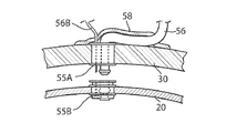
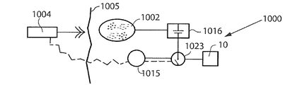
図1および図2aを参照すると、その装置は、液圧流体を収容するための空洞を有する
拡張可能な部材20を有し、その拡張可能な部材20は、尿管32A、32Bから到達し
た尿を収容する膀胱30の内側に配置されている。制御デバイス50が、拡張可能な部材
の拡張、それにより容積を操作する。制御デバイス50は制御アセンブリ52を有し、そ
の制御アセンブリ52は液圧流体用の膀胱作動リザーバ54に接続されており、その膀胱
作動リザーバ54は、膀胱作動リザーバ54と拡張可能な部材20との間で液圧流体を輸
送するための相互接続デバイス56によって拡張可能な部材に接続されている。ポンプ5
3は流体の輸送を助けている。相互接続デバイス56は、膀胱の壁を外科的に切開して通
したチューブ形のデバイスであり、膀胱の壁をそれ自体に縫合するトンネル作製技術によ
ってそれに取り付けられている。相互接続デバイスは、組織の内方成長を可能にすること
によって封止式に固定するネット58によって支持される。図2aでは、相互接続デバイ
ス56は、取外し可能な継ぎ手55に取り付けられており、以下に図2bで説明するよう
に、その継ぎ手55により膀胱作動リザーバが拡張可能な部材に取り付けられている。制
御アセンブリ52は、患者の体内に配置され、液圧流体のための作動ポンプ529、作動
ポンプおよび装置の他のエネルギー消費部分を駆動するエネルギー源521など、装置を
動作させるのに必要な機能要素を複数含む。体外エネルギー供給装置60が無線エネルギ
ーをエネルギー変換デバイス522に伝達し、したがって、エネルギー源521を補うこ
とができる。体外制御ユニット70が、装置を動作させるための体内制御ユニット523
と無線通信する。また、圧力センサ57は、制御アセンブリのセンサ制御機能524に接
続されている。制御アセンブリ52は、言及した機能を含む体内部分52Aと、注入ポー
ト521Bおよび手動で動作可能なスイッチ522Bを含む体外部分52Bとを有する。
皮下にまたは腹腔もしくは骨盤領域あるいは体内の他の任意の適切な部位に、制御デバイ
スの1つまたは複数の部分を植え込むことができる。図2aに示す実施形態は、尿道括約
筋が常に閉鎖する合併症の患者に適合されている。そのため、装置の拡張可能な部材20
は、膀胱から外に尿を押し出すために高い圧力(約60〜80水柱cm)を加える必要が
あり、それにより、尿が尿管32A、32Bを通って逆流する可能性があり、これは腎臓
を損傷する潜在的リスクを伴う。こうした合併症を防止するために、制御デバイスが制限
デバイス59A、59Bを備え、それらの制限デバイス59A、59Bは、尿管を一時的
に収縮させ、拡張可能な部材による尿の排出動作中に尿管を閉じるように構成されている
。制限デバイスは、排出を行う間に一時的に収縮するようにして制御アセンブリによって
動作する。適切な機械式または液圧式に動作する制限デバイスならびにそれらの制御は、
EP1253880、EP1284691、およびEP1263355により詳細に記載
されていることを理解されたい。尿管中の尿の圧力は通常約50水柱cmであるが、短期
間の圧力上昇は腎臓を損傷することがほとんどなく、したがって、制限デバイス59Aお
よび59Bを省略することができる。
Referring to FIGS. 1 and 2a, the device has an
3 helps transport the fluid. The
Wirelessly communicate with. The
One or more portions of the control device can be implanted subcutaneously or in the abdominal or pelvic region or any other suitable site in the body. The embodiment shown in FIG. 2a is adapted for patients with complications where the urethral sphincter always closes. Therefore, the
Need to apply high pressure (about 60-80 cm water column) to push the urine out of the bladder, which can cause the urine to flow back through the
It should be understood that it is described in more detail in EP 1253880, EP 1284691 and EP 1263355. Although the pressure of urine in the ureter is usually about 50 cm of water, short-term pressure increases rarely damage the kidneys, and therefore the
ポンプ53が拡張可能な部材を満たすようにポンプ輸送していないときに、膀胱作動リ
ザーバと拡張可能な部材との間の通路56が自由である場合は、拡張可能な部材は膀胱を
満たす尿によって空になる。別の代替形態では、ポンプ53が、段階的に始動して、例え
ば他で言及したような他の任意の入力センサで制御された圧力によって拡張可能な部材を
空にする。拡張可能な部材20と膀胱作動リザーバ54との間に第2の接続部56Bが導
入されている。第2の接続部は、それが閉じているときに部材20から膀胱作動リザーバ
への流体の輸送を可能にするように適合されている。ポンプ輸送の体積能力が第2の接続
部の空にする能力よりずっと大きい場合は、さらにポンプ53が膀胱作動リザーバ54か
ら部材20に流体を輸送するときは、この接続部を常に開いたままにすることができる。
第2の接続部の導入は装置の任意選択の代替形態と見なされるものである。
If the
The introduction of the second connection is to be considered as an optional alternative to the device.
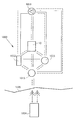
図2bは、図2aの取外し可能な継ぎ手55およびその2つの結合部分55Aおよび5
5Bのより近接した図である。第1の結合部分55Aは制御デバイス50の一部であり、
膀胱作動リザーバ54に接続されている。第2の結合部分55Bは拡張可能な部材20上
に配置されている。2つの結合部分は、拡張可能な部材を制御デバイス50に対して好都
合に取付けまたは取外しするために、簡単に取付け可能であり取外し可能である。したが
って、拡張可能な部材は、適切な器具による尿道を通した介入によって簡単に交換可能に
なる。そのために、拡張可能な部材は、好都合に尿道を貫通するために本質的に円筒形の
細長い形状を想定することができる。図2bに、取外し可能な継ぎ手の一部として第2の
接続部56Bも示す。
FIG. 2b shows the removable joint 55 and its two
FIG. 5B is a closer view. The
Connected to the
図2aおよび図3を参照すると、装置は、遠隔制御装置70からの信号に応答すること
によって動作可能である制御アセンブリ54の作動ポンプを始動することによって動作す
る。膀胱の尿の圧力をモニタリングするための圧力センサ57に制御アセンブリを接続す
ることもできる。例えば、膀胱の壁の伸長もしくは湾曲または圧力を決定するか、または
例えば膀胱内の容積または圧力を感知するために、いくつかの異なるタイプの入力センサ
を使用することができる。多くの場合、それらのセンサは、膀胱を空にする時間であるこ
とを知らせる警告を患者に与えることによって、単に間接的に膀胱を空にしている。こう
した警告は音響的または視覚的に生成される。遠隔制御装置70は、膀胱を空にすること
を制御するか、またはワイヤとして使用される体を介してもしくは無線通信によって通信
するための皮下スイッチ525を制御することができる。次に、ポンプは、液圧流体を膀
胱作動リザーバ54から相互接続デバイス56を介して拡張可能な部材20の空洞に輸送
し、それにより膀胱の体積が増大し、尿道括約筋の閉じる力に打ち勝つ圧力で尿道を通し
て尿を排出し、したがって膀胱の排尿が実現される。こうした動作中には、制御アセンブ
リは、尿管中の尿の逆流を防止するために制限デバイス59A、59Bを閉じるように動
作する。排出の実行が終了し、作動ポンプが停止すると、制限デバイス59A、59Bが
ゆるめられ、したがって尿が膀胱を再度満たすことができる。続いて、圧力センサによっ
てモニタリングされる新規の実行のために準備ができると、拡張可能な部材20は、再度
満たされる尿の圧力によって図2に示すような形状を保持するようにつぶれる。
With reference to FIGS. 2 a and 3, the apparatus operates by starting an actuation pump of the
尿閉の患者には尿失禁の者もいる。こうした場合には、そのシステムには別個の尿道括
約筋が含まれ、制限デバイスが、患者が排尿したくなるまで尿道を閉じている。こうした
場合は、膀胱内の圧力により、括約筋を開くために力が必要ないので、膀胱を空にするに
はより低い圧力しか必要とされない。その場合は、制限デバイス59Aおよび59Bを省
略することができる。
Some patients with urinary retention have incontinence. In such cases, the system includes a separate urethral sphincter and the restriction device closes the urethra until the patient wants to urinate. In such cases, less pressure is needed to empty the bladder because pressure in the bladder does not require force to open the sphincter. In that case, the limiting
膀胱作動リザーバ54を体内のどの位置に配置してもよいが、腹腔中が好ましく、膀胱
の上または骨盤領域に配置することができる。膀胱作動リザーバ中の液体の量を、注入ポ
ート521Bと、体内の特別な注入ポートの針の到達範囲内に配置された皮下リザーバ5
26とを使用することによって、流体で較正することができる。皮下リザーバを省略する
こともでき、拡張可能な部材を満たし空にするために注入ポートのみを使用することもで
きる。説明した実施形態では、尿の排出プロセスの期間/力を制御するためには、例えば
、尿の圧力、またはより簡単には膀胱の拡張可能な部材の内側の圧力を測定する圧力セン
サからのデータにより、制御アセンブリの論理によって作動ポンプを制御することも考え
られる。拡張可能な部材はその部材内で使用される圧力の範囲内では伸縮性があってもよ
く、単に可撓性しかなくてもよいことに留意されたい。図3に、尿を排出させるときの図
2の装置を(制御デバイス50なしで)示す。次に、制限デバイス59A、59Bは、尿
管32A、32Bを閉じ、尿道括約筋59Cを開く。図4に、膀胱が尿で再度満たされて
おり、液圧流体が膀胱作動リザーバ54に戻っているときの図3の装置を示す。今は、制
限デバイス59A、59Bは開いており、尿道括約筋59Cが閉じている。図4に、尿管
用の制限デバイスが、膀胱作動リザーバの特別な部分からの液圧流体によって液圧式に動
作する実施形態も示す。拡張可能な部材に加えられる尿の圧力の結果リザーバの残りの部
分が満たされるときに、制限デバイスを動作させるための液圧流体をリザーバから移動さ
せることができる。図5に、図2aの装置の別の実施形態を示す。ここでは、膀胱作動リ
ザーバ54は、液圧流体を拡張可能な部材20にポンプ輸送するように動作する、制御ア
センブリ52のポンプ527に液圧式に接続される。
The
Can be calibrated with the fluid. The subcutaneous reservoir can be omitted and only the injection port can be used to fill and empty the expandable member. In the described embodiment, to control the duration / force of the urine drainage process, for example, data from a pressure sensor that measures the pressure of urine, or more simply the pressure inside the expandable member of the bladder. It is also conceivable to control the working pump by the logic of the control assembly. It should be noted that the expandable member may be stretchable within the range of pressures used within the member, and may simply be flexible. FIG. 3 shows the apparatus of FIG. 2 (without control device 50) when draining urine. The
説明した実施形態を添付の特許請求の範囲内で改変できることを理解されたい。 It should be understood that the described embodiments can be modified within the scope of the appended claims.
図6に、概略的に説明するかまたは図1から図5に示した、本発明の装置10によって
尿失禁を治療するシステムを示す。そのシステムは患者の腹部に配置される。植込み式エ
ネルギー変換デバイス302が、装置のエネルギー消費構成要素に電力供給ライン303
を介してエネルギーを供給するように適合されている。装置10に非侵襲的にエネルギー
供給する体外エネルギー伝送デバイス304が、少なくとも1つの無線エネルギー信号に
よってエネルギーを伝送する。植込み式エネルギー変換デバイス1002は、無線エネル
ギー信号からのエネルギーを電力供給ライン1003に供給される電気エネルギーに変換
する。
FIG. 6 shows a system for treating urinary incontinence with the
It is adapted to supply energy through. An extracorporeal energy transmission device 304 that non-invasively energizes the
無線エネルギー信号は、音波信号、超音波信号、電磁波信号、赤外線信号、可視光信号
、紫外線信号、レーザ光線信号、マイクロ波信号、電波信号、x線照射信号、およびガン
マ線照射信号から選択された波動信号を含むことができる。あるいは、無線エネルギー信
号は、電場もしくは磁場、または電場と磁場の組合せを含むことができる。
The radio energy signal is a wave selected from a sound wave signal, an ultrasonic signal, an electromagnetic wave signal, an infrared signal, a visible light signal, an ultraviolet signal, a laser beam signal, a microwave signal, a radio wave signal, an x-ray irradiation signal, and a gamma ray irradiation signal. A signal can be included. Alternatively, the wireless energy signal can include an electric or magnetic field, or a combination of electric and magnetic fields.
無線エネルギー伝送デバイス1004は、無線エネルギー信号を搬送するための搬送信
号を伝送することができる。こうした搬送信号は、デジタル信号、アナログ信号、または
デジタル信号とアナログ信号の組合せを含むことができる。その場合は、無線エネルギー
信号は、アナログ信号またはデジタル信号、あるいはアナログ信号とデジタル信号の組合
せを含む。
The wireless
概略的には、エネルギー変換デバイス1002が、エネルギー伝送デバイス1004に
よって伝送される第1の形態の無線エネルギーを、典型的には第1の形態のエネルギーと
は異なる第2の形態のエネルギーに変換するために設けられる。植込み式装置10は、第
2の形態のエネルギーに応答して動作可能である。エネルギー変換デバイス1002は、
エネルギー伝送デバイス1004によって伝送される第1の形態エネルギーを第2の形態
エネルギーに変換するときに、第2の形態エネルギーで装置に直接電力を供給することが
できる。そのシステムはさらに、植込み可能なアキュムレータを含むことができ、アキュ
ムレータを充填するために第2の形態エネルギーが少なくとも部分的に使用される。
In general, the
When the first morphological energy transmitted by the
あるいは、エネルギー伝送デバイス1004によって伝送される無線エネルギーを使用
して、無線エネルギーがエネルギー伝送デバイス1004によって伝送されているときに
、装置に直接電力を供給することができる。そのシステムが、以下に詳細に説明するよう
に、装置を動作させるための作動デバイスを備える場合は、エネルギー伝送デバイス10
04によって伝送される無線エネルギーを使用して、作動デバイスに直接電力を供給して
、装置の動作のための運動エネルギーを生み出すことができる。
Alternatively, the wireless energy transmitted by the
The wireless energy transmitted by 04 can be used to power the actuation device directly to produce kinetic energy for the operation of the device.
第1の形態の無線エネルギーは音波を含むことができ、エネルギー変換デバイス100
2は、音波を電気エネルギーに変換するための圧電素子を含むことができる。第2の形態
のエネルギーは、直流もしくは脈動直流電流または直流と脈動直流電流の組合せ、あるい
は交流または直流と交流の組合せの形態の電気エネルギーを含むことができる。通常、装
置は、電気エネルギーでエネルギー供給される電気構成要素を備える。システムの他の植
込み可能な電気構成要素は、装置の電気構成要素に接続された少なくとも1つの電圧レベ
ル・ガードまたは少なくとも1つの定電流ガードでよい。
The first form of wireless energy may include sound waves and the energy conversion device 100.
2 can include a piezoelectric element for converting sound waves into electrical energy. The energy of the second form can include electrical energy in the form of direct current or pulsating direct current or a combination of direct current and pulsating direct current or alternating current or a combination of direct current and alternating current. Typically, the device comprises electrical components that are energized with electrical energy. The other implantable electrical component of the system may be at least one voltage level guard or at least one constant current guard connected to the electrical component of the device.
任意選択で、第1の形態のエネルギーおよび第2の形態のエネルギーの一方は、磁気エ
ネルギー、運動エネルギー、音響エネルギー、化学エネルギー、放射エネルギー、電磁エ
ネルギー、光エネルギー、原子エネルギー、または熱エネルギーを含むことができる。好
ましくは、第1の形態のエネルギーおよび第2の形態のエネルギーの一方は、非磁気、非
運動、非化学、非音響、非原子力、または非熱である。
Optionally, one of the first form energy and the second form energy comprises magnetic energy, kinetic energy, acoustic energy, chemical energy, radiant energy, electromagnetic energy, optical energy, atomic energy, or thermal energy. be able to. Preferably, one of the first form energy and the second form energy is non-magnetic, non-kinetic, non-chemical, non-acoustic, non-nuclear or non-thermal.
電磁気の無線エネルギーを放出するようにエネルギー伝送デバイスを患者の体の外から
制御することができ、放出された電磁気の無線エネルギーは装置を動作させるために使用
される。あるいは、エネルギー伝送デバイスは、非磁気無線エネルギーを放出するように
患者の体の外から制御され、放出された非磁気無線エネルギーは装置を動作させるために
使用される。
The energy transmission device can be controlled from outside the patient's body to emit electromagnetic wireless energy, and the emitted electromagnetic wireless energy is used to operate the apparatus. Alternatively, the energy transfer device is controlled from outside the patient's body to emit non-magnetic wireless energy, and the released non-magnetic wireless energy is used to operate the apparatus.
体外エネルギー伝送デバイス1004は無線遠隔制御装置も含み、その無線遠隔制御装
置は、装置を非侵襲的に制御するための無線制御信号を伝送する体外信号伝送器を有する
。制御信号は植込み式信号受信器によって受信され、その信号受信器は、植込み式エネル
ギー変換デバイス1002に組み込まれてもよく、それとは別個でもよい。
The extracorporeal
無線制御信号は、周波数、振幅、もしくは位相を変調した信号、またはそれらの組合せ
を含むことができる。あるいは、無線制御信号は、アナログ信号もしくはデジタル信号、
またはアナログ信号とデジタル信号の組合せを含む。あるいは、無線制御信号は、電場も
しくは磁場、または電場と磁場の組合せを含む。
The radio control signal can include a frequency, amplitude, or phase modulated signal, or a combination thereof. Alternatively, the radio control signal is an analog signal or a digital signal,
Or a combination of analog and digital signals. Alternatively, the wireless control signal includes an electric or magnetic field, or a combination of electric and magnetic fields.
無線遠隔制御装置は、無線制御信号を搬送する搬送信号を伝送することができる。こう
した搬送信号は、デジタル信号、アナログ信号、またはデジタル信号とアナログ信号の組
合せを含むことができる。制御信号がアナログ信号もしくはデジタル信号、またはアナロ
グ信号とデジタル信号の組合せを含む場合は、無線遠隔制御装置は、好ましくは、デジタ
ル制御信号またはアナログ制御信号を搬送する電磁気の搬送波信号を伝送する。
The wireless remote control device can transmit a carrier signal that carries a wireless control signal. Such carrier signals can include digital signals, analog signals, or a combination of digital and analog signals. If the control signal includes an analog signal or a digital signal, or a combination of analog and digital signals, the wireless remote control device preferably transmits an electromagnetic carrier signal that carries the digital control signal or analog control signal.
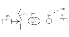
図7に、より概略的なブロック図の形態で図6のシステムを示し、この図は、装置10
と、電力供給ライン1003を介して装置10に電力を供給するエネルギー変換デバイス
1002と、体外エネルギー伝送デバイス1004を示す。垂直の線で概略的に示す患者
の皮膚1005により、線の右側の患者の体内が線の左側の患者の体外から分けられてい
る。
FIG. 7 shows the system of FIG. 6 in the form of a more schematic block diagram, which shows the
And an
図8に、例えば分極エネルギーによって動作可能な電気スイッチ1006の形態の反転
デバイスも装置10を反転させるために患者に植え込まれていることを除いて、図7の実
施形態と同一の本発明の実施形態を示す。スイッチが分極エネルギーによって動作すると
きは、体外エネルギー伝送デバイス1004の無線遠隔制御装置は、分極エネルギーを搬
送する無線信号を伝送し、植込み式エネルギー変換デバイス1002は、電気スイッチ1
006を動作させるために無線分極エネルギーを分極電流に変換する。植込み式エネルギ
ー変換デバイス1002によって電流の極性が変更されると、電気スイッチ1006は、
装置10によって実行される機能を反転させる。
8 of the present invention is the same as the embodiment of FIG. 7, except that an inverting device, for example in the form of an
In order to operate 006, the wireless polarization energy is converted into a polarization current. When the polarity of the current is changed by the implantable
The functions performed by the
図9に、装置10を動作させるための患者に植え込まれた作動デバイス1007が、植
込み式エネルギー変換デバイス1002と装置10との間に設けられていることを除いて
図7の実施形態と同一の実施形態を示す。こうした作動デバイスは、電気サーボモータな
どのモータ1007の形態でよい。モータ1007は、体外エネルギー伝送デバイス10
04の遠隔制御装置が無線信号を、植込み式エネルギー変換デバイス1002の受信器に
伝送するときに、植込み式エネルギー変換デバイス1002からのエネルギーで電力供給
される。
FIG. 9 is identical to the embodiment of FIG. 7 except that an
When the 04 remote controller transmits a wireless signal to the receiver of the implantable
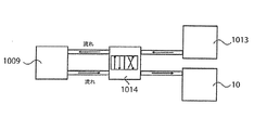
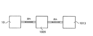
図10に、モータ/ポンプ・ユニット1009および流体リザーバ1010を含むアセ
ンブリ1008の形態であり、患者に植え込まれた、作動デバイスを備えることを除いて
図7の実施形態と同一の実施形態を示す。この場合は、装置10が液圧式に動作し、すな
わち、液圧流体は、装置を動作させるためにモータ/ポンプ・ユニット1009によって
流体リザーバ1010から導管1011を通って装置10までポンプ輸送され、装置を始
動位置に戻すためにモータ/ポンプ・ユニット1009によって装置10から流体リザー
バ1010に戻されるようにポンプ輸送される。植込み式エネルギー変換デバイス100
2は、電力供給ライン1012を介してモータ/ポンプ・ユニット1009に電力を供給
するために、無線エネルギーを電流、例えば分極電流に変換する。
FIG. 10 is in the form of an
2 converts the wireless energy into a current, for example a polarization current, to supply power to the motor /
液圧式に動作する装置10の代わりに、作動デバイスが空気圧作動デバイスを備えるこ
とも想定される。その場合、液圧流体は調整のために使用される加圧空気でよく、流体リ
ザーバの代わりに空気室が用いられる。
Instead of the
これら全ての実施形態では、エネルギー変換デバイス1002は、無線エネルギーによ
って充填されるバッテリまたはコンデンサのような充填可能なアキュムレータを含むこと
ができ、システムの任意のエネルギー消費部分にエネルギーを供給する。
In all these embodiments, the
代替形態として、上記で説明した無線遠隔制御装置の代わりに、患者の手によって、多
くの場合に間接的に、例えば皮膚の下に配置された押しボタンによって接触する、植込み
式部分の手動制御を用いることができる。
As an alternative, instead of the wireless remote control described above, manual control of the implantable part that is contacted by the patient's hand, often indirectly, for example by a push button placed under the skin Can be used.
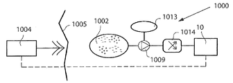
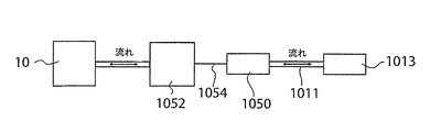
図11に、無線遠隔制御装置を有する体外エネルギー伝送デバイス1004と、この場
合は液圧式に動作する装置10と、植込み式エネルギー変換デバイス1002とを備え、
全て患者に植え込まれている、液圧流体リザーバ1013と、モータ/ポンプ・ユニット
1009と、液圧バルブ・シフト・デバイス1014の形態の反転デバイスとをさらに備
える、本発明の実施形態を示す。当然、液圧動作は、ポンプ輸送の方向を変更するだけで
簡単に実行することもでき、したがって液圧バルブを省略することができる。遠隔制御装
置は、体外エネルギー伝送デバイスとは別個のデバイスでもよく、それに含まれてもよい
。モータ/ポンプ・ユニット1009のモータは電気モータである。体外エネルギー伝送
デバイス1004の無線遠隔制御装置からの制御信号に応答して、植込み式エネルギー変
換デバイス1002は、制御信号によって搬送されたエネルギーからのエネルギーでモー
タ/ポンプ・ユニット1009に電力を供給し、それにより、モータ/ポンプ・ユニット
1009は、液圧流体リザーバ1013と装置10の間で液圧流体を分配する。体外エネ
ルギー伝送デバイス1004の遠隔制御装置は、装置を動作させるために流体がモータ/
ポンプ・ユニット1009によって液圧流体リザーバ1013から装置10にポンプ輸送
される一方の方向と、装置を始動位置に戻すために流体がモータ/ポンプ・ユニット10
09によって装置10から液圧流体リザーバ1013に戻るようにポンプ輸送されるもう
一方の反対の方向との間で、液圧流体の流動方向をシフトするように液圧バルブ・シフト
・デバイス1014を制御する。
FIG. 11 includes an extracorporeal
9 illustrates an embodiment of the invention further comprising a
One direction in which pump
09 controls hydraulic
図7に、無線遠隔制御装置を有する体外エネルギー伝送デバイス1004と、装置10
と、植込み式エネルギー変換デバイス1002と、体外エネルギー伝送デバイス1004
の無線遠隔制御装置によって制御される植込み式体内制御ユニット1015と、植込み式
アキュムレータ1016と、植込み式コンデンサ1017とを備える本発明の実施形態を
示す。体内制御ユニット1015は、エネルギーを装置10に供給するアキュムレータ1
016に、植込み式エネルギー変換デバイス1002から受信した電気エネルギーを貯蔵
する。体外エネルギー伝送デバイス1004の無線遠隔制御装置からの制御信号に応答し
て、体内制御ユニット1015は、アキュムレータ1016からの電気エネルギーを放出
し、放出したエネルギーを電力線1018および1019を介して伝達するか、または電
気エネルギーを植込み式エネルギー変換デバイス1002から電力線1020、電流を安
定させるコンデンサ1017、電力線1021、および装置10の動作のための電力線1
019を介して直接伝達する。
FIG. 7 shows an extracorporeal
An implantable
1 illustrates an embodiment of the present invention comprising an implantable in-
At 016, the electrical energy received from the implantable
Directly communicate via 019.
体内制御ユニットは、好ましくは、患者の体の外からプログラム可能である。好ましい
実施形態では、体内制御ユニットは、予めプログラムされた時間スケジュール、または患
者の任意の可能な物理的パラメータもしくはシステムの任意の関数パラメータを感知する
任意のセンサからの入力に従って、装置10を調整するようにプログラムされる。
The internal control unit is preferably programmable from outside the patient's body. In a preferred embodiment, the internal control unit adjusts the
代替形態によれば、図12の実施形態のコンデンサ1017を省略することができる。
別の代替形態によれば、この実施形態のアキュムレータ1016を省略することができる
。
According to an alternative form, the
According to another alternative, the
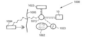
図13に、装置10の動作のためにエネルギーを供給するためのバッテリ1022と、
装置10の動作を切り換えるための電気スイッチ1023も患者に植え込まれていること
を除いて図7の実施形態と同一の実施形態を示す。バッテリ1022が使用されていない
オフ・モードから、バッテリ1022が装置10の動作のためにエネルギーを供給するオ
ン・モードに切り換えるために、電気スイッチ1023を遠隔制御装置によって制御する
ことができ、植込み式エネルギー変換デバイス1002によって供給されたエネルギーに
よって動作させることもできる。
In FIG. 13, a
7 shows an embodiment identical to that of FIG. 7 except that an
図14に、体外エネルギー伝送デバイス1004の無線遠隔制御装置によって制御され
る体内制御ユニット1015も患者に植え込まれていることを除いて図13の実施形態と
同一の実施形態を示す。その場合、電気スイッチ1023は、植込み式エネルギー変換デ
バイス1002によって供給されたエネルギーによって、無線遠隔制御装置により体内制
御ユニット1015の制御が防止されバッテリが使用されていないオフ・モードから、装
置10の動作のためにバッテリ1022から電気エネルギーを放出するように遠隔制御装
置が体内制御ユニット1015を制御することが可能である待機モードに切り換えるよう
に動作する。
FIG. 14 shows an embodiment identical to that of FIG. 13 except that an
図15に、バッテリ1022の代わりにアキュムレータ1016が用いられ、植込み式
構成要素の相互接続が異なることを除いて図14の実施形態と同一の実施形態を示す。そ
の場合、アキュムレータ1016は、植込み式エネルギー変換デバイス1002からのエ
ネルギーを貯蔵する。体外エネルギー伝送デバイス1004の無線遠隔制御装置からの制
御信号に応答して、体内制御ユニット1015は、アキュムレータ1016が使用されて
いないオフ・モードから、アキュムレータ1016が装置10の動作のためにエネルギー
を供給するオン・モードに切り換えるように、電気スイッチ1023を制御する。アキュ
ムレータをコンデンサと組み合わせてもよく、アキュムレータの代わりにコンデンサを用
いてもよい。
FIG. 15 shows an embodiment that is identical to the embodiment of FIG. 14 except that an
図16に、バッテリ1022も患者に植え込まれており、植込み式構成要素の相互接続
が異なることを除いて図15の実施形態と同一の実施形態を示す。体外エネルギー伝送デ
バイス1004の無線遠隔制御装置からの制御信号に応答して、体内制御ユニット101
5は、バッテリ1022が使用されていないオフ・モードから、バッテリ1022が装置
10の動作のために電気エネルギーを供給するオン・モードに切り換えるように、電気ス
イッチ1023を動作させるためにエネルギーを送出するようにアキュムレータ1016
を制御する。
FIG. 16 shows an embodiment identical to that of FIG. 15 except that the
5 delivers energy to operate the
To control.
あるいは、電気スイッチ1023は、無線遠隔制御装置により電気エネルギーを供給す
るようにバッテリ1022を制御することが防止されその無線遠隔制御装置が使用されて
いない、オフ・モードから、無線遠隔制御装置が装置10の動作のために電気エネルギー
を供給するようにバッテリ1022を制御できる待機モードに切り換えるように、アキュ
ムレータ1016によって供給されるエネルギーによって動作することができる。
Alternatively, the
スイッチ1023およびこの出願の他の全てのスイッチを最も範囲が広い実施形態のも
のと解釈すべきであることを理解されたい。これは、トランジスタ、MCU、MCPU、
ASIC、FPGAもしくはDA変換器または他の任意の電子構成要素もしくは回路が電
力のオンとオフを切り換えできることを意味する。好ましくは、スイッチは、体外から制
御されるか、あるいは植込み式体内制御ユニットによって制御される。
It should be understood that
It means that an ASIC, FPGA or DA converter or any other electronic component or circuit can be switched on and off. Preferably, the switch is controlled from outside the body or is controlled by an implantable internal control unit.
図17に、モータ1007と、ギア・ボックス1024の形態の機械式反転デバイスと
、ギア・ボックス1024を制御する体内制御ユニット1015も患者に植え込まれてい
ることを除いて図13の実施形態と同一の実施形態を示す。体内制御ユニット1015は
、(機械式に動作する)装置10によって実行される機能を反転させるようにギア・ボッ
クス1024を制御する。さらに単純なことにモータの方向を電子的に切り換える。最も
範囲が広い実施形態に解釈されるギア・ボックスは、より長い作動ストロークに有利なよ
うに作動デバイスのための力を節約するサーボ機構を表すことができる。
FIG. 17 shows the embodiment of FIG. 13 except that a
図18に、植込み式構成要素の相互接続が異なることを除いて図24の実施形態と同一
の本発明の実施形態を示す。したがって、その場合は、体内制御ユニット1015は、ア
キュムレータ1016、適切にはコンデンサが電気スイッチ1023を始動させてオン・
モードに切り換えるときに、バッテリ1022によって電力が供給される。電気スイッチ
1023がオン・モードのときは、体内制御ユニット1015は、エネルギー装置10の
動作のためのエネルギーを、供給するように、または供給しないようにバッテリ1022
を制御することが可能である。
FIG. 18 illustrates an embodiment of the present invention that is identical to the embodiment of FIG. 24 except that the interconnection of the implantable components is different. Therefore, in that case, the in-
When switching to the mode, power is supplied by the
Can be controlled.
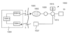
図19に、様々な通信の選択肢を実現するための、装置の植込み式構成要素の考えられ
る組合せを概略的に示す。基本的に、装置10と、体内制御ユニット1015と、モータ
またはポンプ・ユニット1009と、体外無線遠隔制御装置を含む体外エネルギー伝送デ
バイス1004がある。すでに上記で説明したように、無線遠隔制御装置は、体内制御ユ
ニット1015によって受信された制御信号を伝送し、その体内制御ユニット1015は
装置の様々な植込み式構成要素を制御する。
FIG. 19 schematically shows possible combinations of implantable components of the device to realize various communication options. Basically, there is an extracorporeal
好ましくは、センサまたは測定デバイス1025を備えるフィードバック・デバイスを
、患者の物理的パラメータを感知するために患者に植え込むことができる。物理的パラメ
ータは、圧力、容積、直径、伸長、延長、拡張、移動、湾曲、伸縮性、筋収縮、神経イン
パルス、体温、血圧、血流、心拍、および呼吸からなる群から選択された少なくとも1つ
でよい。センサは、上記の物理的パラメータのいずれも感知することができる。例えば、
センサは圧力センサまたは運動性センサでよい。あるいは、関数パラメータを感知するよ
うにセンサ1025を構成することができる。関数パラメータは、植込み式エネルギー源
を充填するためにエネルギーを伝達するように互いに関連付けることができ、電気、任意
の電気的パラメータ、圧力、容積、直径、伸長、延長、拡張、移動、湾曲、伸縮性、温度
、および流れからなるパラメータの群から選択された少なくとも1つをさらに含むことが
できる。
Preferably, a feedback device comprising a sensor or
The sensor may be a pressure sensor or a motility sensor. Alternatively,
体内制御ユニットに、または好ましくは体内制御ユニットを介して外に体外制御ユニッ
トにフィードバックを送ることができる。エネルギー伝達システム、または受信器および
伝送器を有する別個の通信システムを介して、フィードバックを体外に送出することがで
きる。
Feedback can be sent to the external control unit to the internal control unit or preferably via the internal control unit. Feedback can be sent out of the body via an energy transfer system or a separate communication system having a receiver and a transmitter.
体内制御ユニット1015、あるいは体外エネルギー伝送デバイス1004の体外無線
遠隔制御装置は、センサ1025からの信号に応答して装置10を制御することができる
。感知した物理的パラメータの情報を体外無線遠隔制御装置に送るために、トランシーバ
をセンサ1025と組み合わせることができる。無線遠隔制御装置は信号伝送器またはト
ランシーバを備えることができ、体内制御ユニット1015は信号受信器またはトランシ
ーバを備えることができる。あるいは、無線遠隔制御装置は信号受信器またはトランシー
バを備えることができ、体内制御ユニット1015は信号伝送器またはトランシーバを備
えることができる。上記のトランシーバ、伝送器、および受信器を使用して、装置10に
関する情報またはデータを患者の体内から体外に送ることができる。
The in-
モータ/ポンプ・ユニット1009と、モータ/ポンプ・ユニット1009に電力を与
えるバッテリ1022が植え込まれている場合は、バッテリ1022の充填に関する情報
をフィードバックすることができる。より正確にするには、バッテリまたはアキュムレー
タをエネルギーで充填するときに、前記充填プロセスに関するフィードバック情報を送信
し、それに従ってエネルギー供給を変更する。
If a motor /
図20に、装置10が患者の体外から調整される代替の実施形態を示す。システム10
00はバッテリ1022を備え、バッテリ1022は皮下の電気スイッチ1026を介し
て装置10に接続されている。したがって、装置10の調整は、手動で皮下スイッチを押
し、それにより装置10の動作がオンとオフで切り換えられることによって、非侵襲的に
実行される。図示の実施形態は単純化したものであり、体内制御ユニットまたは本出願で
開示した他の任意の部分など、追加の構成要素をシステムに追加できることが理解されよ
う。皮下スイッチを2つ使用することもできる。好ましい実施形態では、1つの植込み式
スイッチが、ある所定の動作を実行するように情報を体内制御ユニットに送信し、患者が
再度スイッチを押すと動作が反転する。
FIG. 20 illustrates an alternative embodiment in which the
00 includes a
図21に、システム1000が装置に液圧式に接続された液圧流体リザーバ1013を
備える代替の実施形態を示す。装置に接続された液圧リザーバを手で押すことによって非
侵襲的な調整が行われる。
FIG. 21 illustrates an alternative embodiment in which the
そのシステムは、体外データ通信器と、体外データ通信器と通信する植込み可能な体内
データ通信器を含むことができる。体内通信器が体外データ通信器に装置または患者に関
するデータを供給し、かつ/または体外データ通信器が体内データ通信器にデータを供給
する。
The system can include an external data communicator and an implantable in-vivo data communicator in communication with the external data communicator. An in-vivo communicator provides data relating to the device or patient to the extracorporeal data communicator and / or an extracorporeal data communicator provides data to the in-vivo data communicator.
図22に、システムの機構を概略的に示し、その機構は、装置10の植込み式エネルギ
ー消費構成要素に接続された植込み式体内エネルギー受信器1002に正確な量のエネル
ギーを供給するために、装置もしくはシステムの少なくとも1つの関数パラメータまたは
患者の物理的パラメータに関するフィードバック情報を提供するように患者の体内から体
外に情報を送信できる。こうしたエネルギー受信器1002は、エネルギー源および/ま
たはエネルギー変換デバイスを含むことができる。簡単に説明すると、無線エネルギーは
、患者の外側に位置する体外エネルギー源1004aから伝送され、患者の内側に位置す
る体内エネルギー受信器1002によって受信される。体内エネルギー受信器は、スイッ
チ1026を介して装置10のエネルギー消費構成要素に受信したエネルギーを直接また
は間接的に供給するように適合されている。エネルギー・バランスは、体内エネルギー受
信器1002によって受信したエネルギーと、装置10のために使用されるエネルギーと
の間で決定され、次いで、無線エネルギーの伝送は、決定されたエネルギー・バランスに
基づいて制御される。したがって、エネルギー・バランスは、適切に、過度の温度上昇な
しに装置10を動作させるのに十分な、必要なエネルギーの正確な量を正確に提示する。
FIG. 22 schematically shows the mechanism of the system, which is used to supply an accurate amount of energy to an implantable
図23では、患者の皮膚は垂直の線1005によって示される。ここでは、エネルギー
受信器は、患者の体内に、好ましくは患者の皮膚1005のすぐ下に配置されたエネルギ
ー変換デバイス1002を備える。概略的には、植込み式エネルギー変換デバイス100
2を、腹部、胸郭、(例えば腹壁の)筋膜、皮下に、または他の任意の適切な位置に配置
することができる。植込み式エネルギー変換デバイス1002は、体外エネルギー源10
04aから伝送される無線エネルギーEを受信するように適合されており、その体外エネ
ルギー源1004aは、植込み式エネルギー変換デバイス1002の近傍の患者の皮膚1
005の外側に位置する体外エネルギー伝送デバイス1004に設けられる。
In FIG. 23, the patient's skin is indicated by a
2 can be placed in the abdomen, thorax, fascia (eg of the abdominal wall), subcutaneous, or any other suitable location. Implantable
Adapted to receive the wireless energy E transmitted from 04a, the extracorporeal energy source 1004a is the patient's
The external
当技術分野でよく知られているように、無線エネルギーEは、一般に、体外エネルギー
源1004aに配置された一次コイルと、植込み式エネルギー変換デバイス1002に配
置された隣接する二次コイルとを含むデバイスなど、任意の適切な経皮エネルギー伝達(
TET)デバイスによって伝達することができる。電流が一次コイルを通して供給される
と、電圧の形態のエネルギーが二次コイルに誘導され、例えば入ってくるエネルギーを蓄
電可能なバッテリまたはコンデンサなどの植込み式エネルギー源に貯蔵した後で、これを
利用して装置の植込み式エネルギー消費構成要素に電力を供給することができる。しかし
、本発明は、概して、どんな特定のエネルギー伝達技法、TETデバイス、またはエネル
ギー源にも限定されず、任意の種類の無線エネルギーを使用することができる。
As is well known in the art, wireless energy E generally includes a primary coil disposed in an extracorporeal energy source 1004a and an adjacent secondary coil disposed in an implantable
TET) device. When current is supplied through the primary coil, energy in the form of voltage is induced in the secondary coil, which can be used after storing the incoming energy in an implantable energy source such as a battery or capacitor that can store electricity, for example. Power can then be supplied to the implantable energy consuming component of the device. However, the present invention is generally not limited to any particular energy transfer technique, TET device, or energy source, and any type of wireless energy can be used.
植込み式エネルギー受信器から受信するエネルギー量を、装置の植込み式構成要素によ
って使用されるエネルギーと比較することができる。そのとき、用語「使用されるエネル
ギー」は、装置の植込み式構成要素によって貯蔵されたエネルギーも含むことが理解され
る。制御デバイスが体外制御ユニット1004bを含み、その体外制御ユニット1004
bは、決定されたエネルギー・バランスに基づいて、伝達されるエネルギーの量を調整す
るように体外エネルギー源1004aを制御する。正確なエネルギー量を伝達するために
、エネルギー・バランスおよび要求エネルギー量が、スイッチ1026と装置10の間に
接続された植込み式体内制御ユニット1015を含む決定デバイスによって決定される。
したがって、装置10の特徴を測定する適切なセンサなど(図示せず)によって得られる
様々な測定値を受信するように、体内制御ユニット1015を構成することができ、装置
10の適切な動作のために必要な要求エネルギー量がある程度反映される。さらに、患者
の現在の状態を、患者の状態を反映するパラメータを提供するために適切な測定デバイス
またはセンサによって検出することもできる。したがって、こうした特徴および/または
パラメータは、電力消費、動作モードおよび温度などの装置10の現在の状態ならびに体
温、血圧、心拍、および呼吸などのパラメータに反映された患者の状態に関連してよい。
患者の他の種類の物理的パラメータおよびデバイスの関数パラメータは別に記載する。
The amount of energy received from the implantable energy receiver can be compared to the energy used by the implantable component of the device. The term “energy used” is then understood to include energy stored by the implantable component of the device. The control device includes an
b controls the external energy source 1004a to adjust the amount of energy transmitted based on the determined energy balance. In order to convey the correct amount of energy, the energy balance and the required amount of energy are determined by a decision device that includes an implantable in-
Accordingly, the
Other types of patient physical parameters and device function parameters are listed separately.
さらに、アキュムレータ1016の形態のエネルギー源を、任意選択で、装置10が後
で使用する受信エネルギーを蓄積するために、制御ユニット1015を介して植込み式エ
ネルギー変換デバイス1002に接続することができる。あるいは、またはさらに、やは
り要求エネルギー量を反映するこうしたアキュムレータの特徴を測定することもできる。
アキュムレータの代わりに蓄電可能なバッテリを使用することができ、測定した特徴は、
エネルギー消費電圧、温度などの任意の電気的パラメータなど、バッテリの現在の状態に
関するものでよい。十分な電圧および電流を装置10に供給し、さらに過熱を避けるため
に、正確なエネルギー量、すなわち少なすぎず、多すぎない量を植込み式エネルギー変換
デバイス1002から受信することによってバッテリを最適に充填すべきであることが明
確に理解される。アキュムレータは、対応する特徴を有するコンデンサであってもよい。
Furthermore, an energy source in the form of an
Instead of an accumulator, a battery that can store electricity can be used.
It may relate to the current state of the battery, such as any electrical parameters such as energy consumption voltage, temperature. Optimal filling of the battery by receiving an accurate amount of energy, i.e. not too little, not too much, from the implantable
例えば、バッテリの現在の状態を決定するためにバッテリの特徴を定期的に測定するこ
とができ、次いで、それを体内制御ユニット1015の適切な格納手段に状態情報として
格納することができる。したがって、新規の測定が行われるときはいつでも、それに従っ
てバッテリ状態の格納した情報を更新することができる。このようにして、バッテリを最
適な状態に維持するように正確なエネルギー量を伝達することによって、バッテリの状態
を「較正」することができる。
For example, battery characteristics can be measured periodically to determine the current state of the battery, which can then be stored as state information in appropriate storage means of the
したがって、決定デバイスの体内制御ユニット1015は、上記で言及した装置10の
センサまたは測定デバイス、または患者、または使用する場合は植込み式エネルギー源、
あるいはそれらの任意の組合せで行った測定に基づいて、エネルギー・バランスおよび/
または現在の要求エネルギー量(単位時間当たりのエネルギーまたは蓄積されたエネルギ
ー)を決定するように適合されている。体内制御ユニット1015はさらに、体内信号伝
送器1027に接続されており、その体内信号伝送器1027は、決定された要求エネル
ギー量を反映する制御信号を体外制御ユニット1004bに接続された体外信号受信器1
004cに伝送するように構成されている。次いで、受信した制御信号に応答して、体外
エネルギー源1004aから伝送されるエネルギー量を調整することができる。
Thus, the in-
Or based on measurements made with any combination thereof, energy balance and / or
Or it is adapted to determine the current amount of energy required (energy per unit time or stored energy). The in-
It is configured to transmit to 004c. The amount of energy transmitted from the extracorporeal energy source 1004a can then be adjusted in response to the received control signal.
あるいは、決定デバイスは、体外制御ユニット1004bを含むことができる。この代
替形態では、体外制御ユニット1004bに直接センサの測定値を伝送することができ、
エネルギー・バランスおよび/または現在の要求エネルギー量を体外制御ユニット100
4bによって決定することができ、したがって、体内制御ユニット1015の上記で説明
した機能を体外制御ユニット1004bに統合することができる。その場合は、体内制御
ユニット1015を省略することができ、センサの測定値は体内信号伝送器1027に直
接供給され、その体内信号伝送器1027は、それらの測定値を体外信号受信器1004
cおよび体外制御ユニット1004bに対して送信する。次いで、それらのセンサの測定
値に基づいて体外制御ユニット1004bによって、エネルギー・バランスおよび現在の
要求エネルギー量を決定することができる。
Alternatively, the determination device can include an
The energy balance and / or the current amount of energy required for the external control unit 100
4b, and thus the above-described functions of the
c and to the
したがって、図22の機構による現在の解決策は、要求エネルギーを示す情報のフィー
ドバックを用い、これは、受信エネルギーと比較した、例えば、装置の植込み式エネルギ
ー消費構成要素によって使用されるエネルギーの割合と比較されるエネルギー量、エネル
ギー差、またはエネルギー受信割合を基準にした、実際のエネルギーの使用に基づいてい
るので以前の解決策より効果的である。装置は、消費、または植込み式エネルギー源など
へのエネルギー貯蔵のために受信エネルギーを使用することができる。したがって、関連
がありかつ必要な場合に、さらに実際のエネルギー・バランスを決定するためのツールと
して、上記で説明した異なるパラメータを使用することになる。しかし、特に装置を動作
させるために体内で行われる動作のために、本質的にこうしたパラメータを必要としてよ
い。
Thus, the current solution by the mechanism of FIG. 22 uses feedback of information indicating the required energy, which is, for example, the percentage of energy used by the implantable energy consumption component of the device compared to the received energy. It is more effective than previous solutions because it is based on actual energy usage based on the amount of energy compared, energy difference, or energy reception rate. The device can use the received energy for consumption or energy storage, such as in an implantable energy source. Therefore, the different parameters described above will be used as a tool to further determine the actual energy balance when relevant and necessary. However, these parameters may be essential in nature, particularly for operations performed in the body to operate the device.
無線信号、IR(赤外線)信号、または超音波信号など、適切な信号伝達手段を用いて
、体内信号伝送器1027および体外信号受信器1004cを別個のユニットとして実装
することができる。あるいは、基本的に同じ伝送技法を用いてエネルギー伝達に対して逆
方向に制御信号を運ぶように、体内信号伝送器1027および体外信号受信器1004c
を、それぞれ植込み式エネルギー変換デバイス1002および体外エネルギー源1004
aに組み込むことができる。制御信号は、周波数、位相、または振幅に関して変調するこ
とができる。
The
, Implantable
can be incorporated into a. The control signal can be modulated with respect to frequency, phase, or amplitude.
したがって、受信器および伝送器を含む別個の通信システムによって、フィードバック
情報を伝達することもでき、エネルギー・システムに組み込むこともできる。本発明によ
れば、こうした一体型の情報フィードバックおよびエネルギー・システムは、第1の体内
コイルおよび第1のコイルに接続された第1の電子回路を有する、無線エネルギーを受信
するための植込み可能な体内エネルギー受信器を備え、第2の体外コイルおよび第2のコ
イルに接続された第2の電子回路を有する、無線エネルギーを伝送するための体外エネル
ギー伝送器を備える。エネルギー伝送器の第2の体外コイルは、エネルギー受信器の第1
のコイルによって受信される無線エネルギーを伝送する。このシステムはさらに、第1の
電子回路に対する第1の体内コイルの接続のオンとオフを切り換える電力スイッチを備え
、電力スイッチが第1の電子回路に対する第1の体内コイルの接続のオンとオフを切り換
えるときに、第2の体外コイルの負荷のインピーダンスの変化の形態で第1のコイルの電
荷に関するフィードバック情報が体外エネルギー伝送器によって受信される。こうしたシ
ステムを図17の機構に実装する際に、スイッチ1026は、体内制御ユニット1015
から分離して制御されるか、または体内制御ユニット1015に組み込まれる。スイッチ
1026を最も範囲が広い実施形態に解釈すべきであることを理解されたい。これは、ト
ランジスタ、MCU、MCPU、ASIC、FPGAもしくはDA変換器または他の任意
の電子構成要素もしくは回路が電力のオンとオフを切り換えできることを意味する。
Thus, feedback information can be communicated and incorporated into the energy system by a separate communication system including a receiver and a transmitter. In accordance with the present invention, such an integrated information feedback and energy system has an implantable for receiving wireless energy having a first body coil and a first electronic circuit connected to the first coil. An extracorporeal energy transmitter for transmitting wireless energy, comprising an in-vivo energy receiver and having a second extracorporeal coil and a second electronic circuit connected to the second coil. The second extracorporeal coil of the energy transmitter is the first of the energy receiver.
The radio energy received by the coil of is transmitted. The system further includes a power switch that switches on and off the connection of the first body coil to the first electronic circuit, the power switch turning on and off the connection of the first body coil to the first electronic circuit. When switching, feedback information regarding the charge of the first coil in the form of a change in the impedance of the load of the second extracorporeal coil is received by the extracorporeal energy transmitter. When such a system is implemented in the mechanism of FIG.
It is controlled separately from or integrated into the
結論としては、図22に示すエネルギー供給機構は、基本的には以下のようにして動作
することができる。エネルギー・バランスは、最初に、決定デバイスの体内制御ユニット
1015によって決定される。要求エネルギー量を反映する制御信号も体内制御ユニット
1015によって生成され、その制御信号は、体内信号伝送器1027から体外信号受信
器1004cに伝送される。あるいは、代わりに上記で言及したように、実装形態に応じ
て体外制御ユニット1004bによってエネルギー・バランスを決定することができる。
その場合は、制御信号は、様々なセンサからの測定結果を搬送することができる。次いで
、決定されたエネルギー・バランスに基づいて、例えば受信した制御信号に応答して、体
外エネルギー源1004aから放出されたエネルギー量を体外制御ユニット1004bに
よって調整することができる。このプロセスは、進行しているエネルギー伝達中に特定の
間隔で間欠的に繰り返すこともでき、エネルギー伝達中にある程度連続して実行すること
もできる。
In conclusion, the energy supply mechanism shown in FIG. 22 can basically operate as follows. The energy balance is first determined by the
In that case, the control signal can carry measurement results from various sensors. The amount of energy released from the extracorporeal energy source 1004a can then be adjusted by the
伝達されたエネルギーの量は、概して、電圧、電流、振幅、波動周波数、およびパルス
の特徴など、体外エネルギー源1004aの様々な伝送パラメータを調節することによっ
て調整することができる。
The amount of energy transferred can generally be adjusted by adjusting various transmission parameters of the external energy source 1004a, such as voltage, current, amplitude, wave frequency, and pulse characteristics.
このシステムを使用して、体内コイルに関する体外コイルの最適な位置を見つけると共
に、エネルギー伝達を最適化するために、システムをさらに較正するように、TETシス
テムのコイル間の結合係数についての情報を得ることもできる。単純にこの場合に伝達さ
れるエネルギー量を受信するエネルギー量と比較する。例えば、体外コイルが移動する場
合は、結合係数は変わることがあり、移動が正確になると、体外コイルがエネルギー伝達
のための最適な位置を見つけることもできる。好ましくは、体外コイルは、結合係数が最
大になる前に決定デバイスのフィードバック情報を実現するように、伝達されるエネルギ
ー量を較正するように適合されている。
This system is used to find the optimal position of the extracorporeal coil with respect to the intracorporeal coil and obtain information about the coupling coefficient between the coils of the TET system to further calibrate the system to optimize energy transfer. You can also. Simply compare the amount of energy transmitted in this case with the amount of energy received. For example, if the extracorporeal coil moves, the coupling coefficient may change, and once the movement is accurate, the extracorporeal coil can find the optimal position for energy transfer. Preferably, the extracorporeal coil is adapted to calibrate the amount of energy transmitted so as to achieve the feedback information of the decision device before the coupling coefficient is maximized.
この結合係数の情報は、エネルギー伝達中にフィードバックとして使用することもでき
る。こうした場合には、本発明のエネルギー・システムは、第1の体内コイルおよび第1
のコイルに接続された第1の電子回路を有する、無線エネルギーを受信する植込み可能な
体内エネルギー受信器と、第2の体外コイルおよび第2のコイルに接続された第2の電子
回路を有する、無線エネルギーを伝送する体外エネルギー伝送器とを備える。エネルギー
伝送器の第2の体外コイルは、エネルギー受信器の第1のコイルによって受信される無線
エネルギーを伝送する。そのシステムはさらに、フィードバック情報として第1のコイル
で受信されるエネルギー量を通信するフィードバック・デバイスを備え、第2の電子回路
は決定デバイスを含み、その決定デバイスは、フィードバック情報を受信し、第1のコイ
ルと第2のコイルの間の結合係数を得るために、第2のコイルによって伝達されたエネル
ギー量を第1のコイルで受信されたエネルギー量に関するフィードバック情報と比較する
。エネルギー伝送器は、得られた結合係数に応答して、伝送されたエネルギーを調整する
ことができる。
This coupling coefficient information can also be used as feedback during energy transfer. In such cases, the energy system of the present invention includes the first body coil and the first
An implantable in-vivo energy receiver for receiving wireless energy having a first electronic circuit connected to the second coil, and a second electronic circuit connected to the second extracorporeal coil and the second coil. An extracorporeal energy transmitter for transmitting wireless energy. The second extracorporeal coil of the energy transmitter transmits wireless energy received by the first coil of the energy receiver. The system further comprises a feedback device that communicates the amount of energy received by the first coil as feedback information, the second electronic circuit includes a determination device, the determination device receiving the feedback information, In order to obtain a coupling coefficient between one coil and the second coil, the amount of energy transmitted by the second coil is compared with feedback information relating to the amount of energy received by the first coil. The energy transmitter can adjust the transmitted energy in response to the resulting coupling coefficient.
図23を参照すると、非侵襲的な操作を可能にするように装置を動作させるためのエネ
ルギーの無線伝達を上記で説明したが、装置はワイヤでつなげたエネルギーでも動作でき
ることが理解されよう。こうした一例を図18に示し、その図では、体外スイッチ102
6は、装置10を動作させる電気モータ1007など、体外エネルギー源1004aと作
動デバイスの間に相互接続されている。体外制御ユニット1004bが、装置10が適切
な動作を行うように体外スイッチ1026の動作を制御する。
Referring to FIG. 23, it has been described above that wireless transmission of energy to operate the device to allow non-invasive operation, it will be appreciated that the device can also operate with wire-connected energy. An example of this is shown in FIG. 18, in which the extracorporeal switch 102 is shown.
6 is interconnected between an external energy source 1004a and an actuation device, such as an
図24に、受信したエネルギーを装置10に供給し装置10によって使用できる方法に
関する異なる実施形態を示す。図17の例と同様に、体内エネルギー受信器1002が、
伝送制御ユニット1004bによって制御される体外エネルギー源1004aから無線エ
ネルギーEを受信する。体内エネルギー受信器1002は、エネルギーを定電圧で装置1
0に供給する定電圧回路を備えることができ、これを図では破線のボックス「定電圧V」
で示している。体内エネルギー受信器1002はさらに、装置10に定電流でエネルギー
を供給する定電流回路を備えることができ、これを図では破線のボックス「定電流C」で
示す。
FIG. 24 illustrates different embodiments for a method in which received energy can be supplied to and used by the
The wireless energy E is received from the extracorporeal energy source 1004a controlled by the
A constant voltage circuit for supplying 0 can be provided, which is indicated by a dashed box “constant voltage V” in the figure
Is shown. The
装置10はエネルギー消費部分10aを備え、そのエネルギー消費部分10aは、モー
タ、ポンプ、制限デバイス、または電気動作のためにエネルギーを必要とする他の任意の
医療機器でよい。装置10はさらに、体内エネルギー受信器1002から供給されたエネ
ルギーを貯蔵するエネルギー貯蔵デバイス10bを備えることができる。したがって、供
給されるエネルギーは、エネルギー消費部分10aによって直接消費されても、エネルギ
ー貯蔵デバイス10bに貯蔵されてもよく、または供給されるエネルギーは、一部が消費
され、一部が貯蔵されてもよい。装置10はさらに、体内エネルギー受信器1002から
供給されたエネルギーを安定化するエネルギー安定化ユニット10cを備えることができ
る。したがって、エネルギーを増減させながら供給することができ、そのため消費または
貯蔵の前にエネルギーを安定化する必要がある。
The
体内エネルギー受信器1002から供給されたエネルギーはさらに、装置10によって
消費および/または貯蔵される前に、装置10の外側に位置する別個のエネルギー安定化
ユニット1028によって蓄積および/または安定化されてよい。あるいは、エネルギー
安定化ユニット1028を体内エネルギー受信器1002に組み込むことができる。いず
れの場合でも、エネルギー安定化ユニット1028は、定電圧回路および/または定電流
回路を備えることができる。
The energy supplied from the
図22および図24に、図示の様々な機能上の構成要素および要素を配置できる方法お
よび互いに接続できる方法に関する、いくつかの可能であるが、非限定的な実装形態の選
択肢を示していることに留意されたい。しかし、本発明の範囲内で多くの変更および改変
を行うことができることを当業者は簡単に理解するであろう。
FIGS. 22 and 24 show some possible but non-limiting implementation options for the various functional components shown and how they can be arranged and connected to each other. Please note that. However, one of ordinary skill in the art will readily appreciate that many variations and modifications can be made within the scope of the present invention.
図25に、無線エネルギーの伝送を制御するシステムまたはエネルギー・バランス制御
システムの設計案のうちの1つであるエネルギー・バランス測定回路を概略的に示す。回
路は出力信号を有し、その出力信号は、2.5Vを中心とし、エネルギーのアンバランス
と比例関係にある。こうした信号の導関数は、値が上下しているかどうかと、そうした変
化が生じる速度を示す。受信エネルギー量が装置の植込み式構成要素によって使用される
エネルギーより少ない場合は、より多くのエネルギーが伝達され、したがって、エネルギ
ー源が充填される。回路からの出力信号は、典型的には、A/D変換器に供給され、デジ
タル・フォーマットに変換される。次いで、そのデジタル情報を体外エネルギー伝送デバ
イスに送信し、そこで伝送されたエネルギーのレベルを調節することができる。別の可能
性は、比較器を使用する完全なアナログ・システムを有することであり、その比較器は、
エネルギー・バランスのレベルを特定の最大閾値および最小閾値と比較し、バランスがず
れて最大/最小ウィンドウから出てしまう場合は、情報を体外エネルギー伝送デバイスに
送信する。
FIG. 25 schematically shows an energy balance measurement circuit which is one of the design proposals for a system for controlling the transmission of wireless energy or an energy balance control system. The circuit has an output signal, which is centered around 2.5V and is proportional to the energy imbalance. The derivative of these signals indicates whether the value is going up and down and the rate at which such changes occur. If the amount of received energy is less than the energy used by the implantable component of the device, more energy is transmitted and therefore the energy source is filled. The output signal from the circuit is typically supplied to an A / D converter and converted to a digital format. The digital information can then be sent to an external energy transmission device where the level of energy transmitted can be adjusted. Another possibility is to have a complete analog system that uses a comparator,
The level of energy balance is compared with specific maximum and minimum thresholds, and information is sent to the extracorporeal energy transmission device if the balance is out of balance and leaves the maximum / minimum window.
概略図25に、誘導性エネルギーの伝達を使用して患者の体外から本発明の装置の植込
み式エネルギー構成要素にエネルギーを伝達するシステムの回路の実装形態を示す。誘導
性エネルギー伝達システムは、典型的には、体外伝送コイルおよび体内受信コイルを使用
する。受信コイルL1は概略図3に含まれ、システムの伝送部分は含まれない。
FIG. 25 shows a circuit implementation of a system for transferring energy from outside the patient's body to the implantable energy component of the device of the present invention using inductive energy transfer. Inductive energy transfer systems typically use an extracorporeal transmission coil and an in-vivo receiving coil. The receiving coil L1 is included schematically in FIG. 3 and does not include the transmission portion of the system.
エネルギー・バランスの概略的な概念および体外エネルギー伝送器への情報の伝送方法
の実装形態は、当然、多数の異なる方法で実装することができる。情報を評価および伝送
する、概略図25および上記で説明した方法は、制御システムの実装方法の例としてのみ
解釈すべきである。
The general concept of energy balance and the implementation of the method of transmitting information to the external energy transmitter can of course be implemented in a number of different ways. The schematic 25 and the method described above for evaluating and transmitting information should only be interpreted as an example of how to implement a control system.
回路の詳細 図25では、記号Y1、Y2、Y3などは、回路内の試験点を記号化して
いる。図の構成要素およびそれぞれの値は、この特定の実装形態で機能する値であり、当
然、これは無数の可能な設計の解決策の一つに過ぎない。
Circuit Details In FIG. 25, symbols Y1, Y2, Y3, etc. symbolize test points in the circuit. The components in the figure and their respective values are those that will work in this particular implementation, and of course this is just one of myriad possible design solutions.
回路に電力を供給するエネルギーは、エネルギー受信コイルL1で受信される。植込み
式構成要素へのエネルギーは、この特定の場合には周波数25kHzで伝送される。エネ
ルギー・バランス出力信号は試験点Y1にある。
The energy for supplying power to the circuit is received by the energy receiving coil L1. The energy to the implantable component is transmitted at a frequency of 25 kHz in this particular case. The energy balance output signal is at test point Y1.
上記のシステムの様々な実施形態を多くの異なる方法で組み合わせることもできると当
業者は認識するであろう。例えば、図8の電気スイッチ1006を図11〜図17の実施
形態のいずれかに組み込むこともでき、図11の液圧バルブ・シフト・デバイス1014
を図10の実施形態に組み込むこともでき、ギア・ボックス1024を図9の実施形態に
組み込むこともできる。スイッチは単に任意の電子回路または構成要素を意味することも
できると認識されたい。
Those skilled in the art will recognize that the various embodiments of the above system can be combined in many different ways. For example, the
Can be incorporated into the embodiment of FIG. 10, and a
図22、図24、および図25に関連して説明した実施形態は、電気的に動作可能な装
置の植込み式エネルギー消費構成要素への無線エネルギーの伝送を制御する方法およびシ
ステムを特定する。こうした方法およびシステムを以下で概略的に定義する。
The embodiments described in connection with FIGS. 22, 24, and 25 identify a method and system for controlling the transmission of wireless energy to an implantable energy consuming component of an electrically operable device. Such methods and systems are generally defined below.
したがって、上記で説明した装置の植込み式エネルギー消費構成要素に供給される無線
エネルギーの伝送を制御する方法が提供される。無線エネルギーEは、患者の体外に位置
する体外エネルギー源から伝送され、患者の体内に位置する体内エネルギー受信器によっ
て受信され、体内エネルギー受信器は、受信したエネルギーを装置の植込み式エネルギー
消費構成要素に直接または間接的に供給するために、そのエネルギー消費構成要素に接続
される。体内エネルギー受信器によって受信されるエネルギーと、装置のために使用され
るエネルギーとの間でエネルギー・バランスが決定される。次いで、体外エネルギー源か
らの無線エネルギーEの伝送は、決定されたエネルギー・バランスに基づいて制御される
。
Accordingly, a method is provided for controlling the transmission of wireless energy supplied to the implantable energy consuming component of the apparatus described above. Wireless energy E is transmitted from an external energy source located outside the patient's body and received by an internal energy receiver located inside the patient's body, the internal energy receiver receiving the received energy from the implantable energy consuming component of the device Connected to its energy consuming component for direct or indirect supply. An energy balance is determined between the energy received by the internal energy receiver and the energy used for the device. The transmission of wireless energy E from the external energy source is then controlled based on the determined energy balance.
体外エネルギー源の一次コイルから体内エネルギー受信器の二次コイルに誘導的に無線
エネルギーを伝送ことができる。エネルギー・バランスの変化を決定して、そのエネルギ
ー・バランスの変化に基づいて無線エネルギーの伝送を制御することができる。体内エネ
ルギー受信器によって受信されたエネルギーと、医療デバイスのために使用されるエネル
ギーとの差を検出して、検出されたエネルギーの差に基づいて無線エネルギーの伝送を制
御することもできる。
Wireless energy can be inductively transmitted from the primary coil of the external energy source to the secondary coil of the internal energy receiver. A change in energy balance can be determined and the transmission of wireless energy can be controlled based on the change in energy balance. The difference between the energy received by the internal energy receiver and the energy used for the medical device can be detected and the transmission of wireless energy can be controlled based on the detected energy difference.
エネルギー伝送を制御するときに、検出されたエネルギー・バランスの変化が、エネル
ギー・バランスが増大していることを示す場合は、伝送される無線エネルギーの量を低減
させることができ、その逆も可能である。エネルギー伝送の減少/増加はさらに、検出し
た変化量に一致してよい。
When controlling energy transmission, if the detected energy balance change indicates that the energy balance is increasing, the amount of radio energy transmitted can be reduced and vice versa It is. The decrease / increase in energy transmission may further correspond to the detected amount of change.
検出されたエネルギーの差が、受信エネルギーが使用エネルギーより多いことを示す場
合に、伝送される無線エネルギーの量をさらに減少させることができるか、またはその逆
も可能である。そのとき、エネルギー伝送の減少/増加は、検出したエネルギーの差の大
きさと一致してよい。
If the detected energy difference indicates that the received energy is greater than the used energy, the amount of radio energy transmitted can be further reduced, or vice versa. At that time, the decrease / increase in energy transmission may coincide with the magnitude of the detected energy difference.
上記で言及したように、医療デバイスのために使用されるエネルギーを、医療デバイス
を動作させるために消費し、かつ/または医療デバイスの少なくとも1つのエネルギー貯
蔵デバイスに貯蔵することができる。
As mentioned above, energy used for the medical device can be consumed to operate the medical device and / or stored in at least one energy storage device of the medical device.
医療デバイスの電気的および/または物理的パラメータならびに/あるいは患者の物理
的パラメータが決定されるときは、前記パラメータに基づいて決定された単位時間当たり
の伝送速度に従って消費および貯蔵するためにエネルギーを伝送することができる。伝送
された全エネルギー量を前記パラメータに基づいて決定することもできる。
When electrical and / or physical parameters of a medical device and / or physical parameters of a patient are determined, energy is transmitted for consumption and storage according to a transmission rate per unit time determined based on the parameters. can do. The total amount of energy transmitted can also be determined based on the parameters.
体内エネルギー受信器によって受信された全エネルギー量と、消費および/または貯蔵
された全エネルギー量との間で差が検出され、その検出された差が、前記エネルギー・バ
ランスに関する少なくとも1つの測定した電気的パラメータの時間積分に関係するときは
、エネルギー・バランスに関係してモニタリングされた電圧および/または電流に関して
積分を決定することができる。
A difference is detected between the total amount of energy received by the internal energy receiver and the total amount of energy consumed and / or stored, and the detected difference is at least one measured electricity related to the energy balance. When related to the time integral of the dynamic parameters, the integral can be determined with respect to the monitored voltage and / or current in relation to the energy balance.
消費および/または貯蔵エネルギーの量に関する測定された電気的パラメータの導関数
がある期間にわたって決定されるときは、エネルギー・バランスに関係するモニタリング
された電圧および/または電流に関して導関数を決定することができる。
When the derivative of the measured electrical parameter related to the amount of consumed and / or stored energy is determined over a period of time, determining the derivative with respect to the monitored voltage and / or current related to energy balance it can.
無線エネルギーを伝送するように第1の電気回路から体外エネルギー源に、立ち上がり
および立ち下がりを有する電気パルスを加え、電気パルスの連続する立ち上がりと立ち下
がりの間の第1の時間間隔の長さ、および/または電気パルスの連続する立ち下がりと立
ち上がりの間の第2の時間間隔の長さを変更し、無線エネルギーを伝送することによって
、体外エネルギー源からの無線エネルギーの伝送を制御することができ、電気パルスから
生じる伝送エネルギーは変更された電力を有し、電力の変化は第1および/または第2の
時間間隔の長さに応じて変わる。
Applying an electrical pulse having a rise and fall to the extracorporeal energy source from the first electrical circuit to transmit wireless energy, the length of the first time interval between successive rise and fall of the electrical pulse; And / or by changing the length of the second time interval between successive falling edges of the electrical pulse and transmitting wireless energy, the transmission of wireless energy from the external energy source can be controlled. The transmitted energy resulting from the electrical pulse has altered power, and the change in power varies depending on the length of the first and / or second time interval.
その場合は、電気パルスの周波数は、第1のおよび/または第2の時間間隔を変更する
ときは事実上一定でよい。電気パルスを加えるときは、その電気パルスは、第1のおよび
/または第2の時間間隔の変更を除いて変化がないままでよい。電気パルスの振幅は、第
1のおよび/または第2の時間間隔を変更するときは事実上一定でよい。さらに、連続す
る立ち上がりと立ち下がりの間の第1の時間間隔の長さを変更するだけで電気パルスを変
更することができる。
In that case, the frequency of the electrical pulse may be substantially constant when changing the first and / or second time interval. When applying an electrical pulse, the electrical pulse may remain unchanged except for a change in the first and / or second time interval. The amplitude of the electrical pulse may be substantially constant when changing the first and / or second time interval. Furthermore, the electrical pulse can be changed by simply changing the length of the first time interval between successive rising and falling edges.
2つ以上の電気パルス列を連続して供給することができ、パルス列を印加し、そのパル
ス列が、パルス列の開始点に第1の電気パルスを有し、パルス列の終了点に第2の電気パ
ルスを有するときは、2つ以上のパルス列を連続して供給することができ、第1のパルス
列の第2の電気パルスの立ち下がりと、第2のパルス列の第1の電気パルスの立ち上がり
との間の第2の時間間隔の長さは変更される。
Two or more electrical pulse trains can be supplied in succession, applying a pulse train, the pulse train having a first electrical pulse at the start of the pulse train and a second electrical pulse at the end of the pulse train. Two or more pulse trains can be supplied in succession between the fall of the second electrical pulse of the first pulse train and the rise of the first electrical pulse of the second pulse train. The length of the second time interval is changed.
電気パルスを印加するときは、電気パルスは、事実上の定電流および事実上の定電圧を
有することができる。電気パルスも事実上の定電流および事実上の定電圧を有することが
できる。さらに、電気パルスは、事実上の定周波数を有することもできる。パルス列内の
電気パルスは、同様に、事実上の定周波数を有することができる。
When applying an electrical pulse, the electrical pulse can have a virtually constant current and a virtually constant voltage. The electrical pulse can also have a virtually constant current and a virtually constant voltage. Furthermore, the electrical pulses can have a virtually constant frequency. The electrical pulses in the pulse train can likewise have a virtually constant frequency.
第1の電気回路によって形成された回路および体外エネルギー源は、第1の特性期間ま
たは第1の時定数を有することができ、伝送されるエネルギーを事実上変更するときは、
こうした周波数時間期間は第1の特性期間または時定数の範囲内またはそれより短くてよ
い。
The circuit formed by the first electrical circuit and the extracorporeal energy source can have a first characteristic period or a first time constant, and when changing the transmitted energy in effect,
Such a frequency time period may be within or shorter than the first characteristic period or time constant.
したがって、上記で説明したような装置を備えるシステムも、装置の植込み式エネルギ
ー消費構成要素に供給される無線エネルギーの伝送を制御するために設けられる。最も範
囲が広い意味で、そのシステムは、エネルギー伝送デバイスからの無線エネルギーの伝送
を制御するための制御デバイスと、伝送される無線エネルギーを受信するための植込み可
能な体内エネルギー受信器を備え、その体内エネルギー受信器は、受信したエネルギーを
装置の植込み可能なエネルギー消費構成要素に直接または間接的に供給するためにそれら
のエネルギー消費構成要素に接続されている。そのシステムはさらに、体内エネルギー受
信器によって受信されたエネルギーと、装置の植込み可能なエネルギー消費構成要素で使
用されるエネルギーとの間のエネルギー・バランスを決定するように適合された決定デバ
イスを備え、体外制御ユニットは、決定デバイスによって決定されたエネルギー・バラン
スに基づいて体外エネルギー伝送デバイスからの無線エネルギーの伝送を制御する。
Accordingly, a system comprising a device as described above is also provided for controlling the transmission of wireless energy supplied to the implantable energy consuming component of the device. In its broadest sense, the system comprises a control device for controlling the transmission of wireless energy from the energy transmission device and an implantable internal energy receiver for receiving the transmitted wireless energy, The internal energy receiver is connected to the energy consuming components for supplying received energy directly or indirectly to the implantable energy consuming components of the device. The system further comprises a determination device adapted to determine an energy balance between the energy received by the internal energy receiver and the energy used in the implantable energy consuming component of the apparatus; The extracorporeal control unit controls the transmission of wireless energy from the extracorporeal energy transmission device based on the energy balance determined by the determination device.
さらに、そのシステムは以下うちのいずれかを備えることができる。 Further, the system can include any of the following:
体内エネルギー受信器の二次コイルに誘導して無線エネルギーを伝送するように適合さ
れた、体外エネルギー源中の一次コイル。
A primary coil in an external energy source adapted to induct and transmit wireless energy to a secondary coil of an internal energy receiver.
決定デバイスは、エネルギー・バランスの変化を検出するように適合されており、体外
制御ユニットは、検出されたエネルギー・バランスの変化に基づいて無線エネルギーの伝
送を制御する。
The determination device is adapted to detect a change in energy balance, and the extracorporeal control unit controls transmission of wireless energy based on the detected change in energy balance.
決定デバイスは、体内エネルギー受信器によって受信されたエネルギーと、装置の植込
み可能なエネルギー消費構成要素のために使用されるエネルギーとの差を検出するように
適合されており、体外制御ユニットは、検出したエネルギーの差に基づいて無線エネルギ
ーの伝送を制御する。
The determination device is adapted to detect the difference between the energy received by the internal energy receiver and the energy used for the implantable energy consuming component of the device, and the external control unit detects The transmission of wireless energy is controlled based on the difference in energy.
検出したエネルギー・バランスの変化が、エネルギー・バランスが増大していることを
示す場合に、体外制御ユニットは、伝送された無線エネルギーの量を減少させるように体
外エネルギー伝送デバイスを制御し、またはその逆も可能であり、エネルギー伝送の減少
/増加は検出された変化速度に一致する。
If the detected energy balance change indicates that the energy balance is increasing, the extracorporeal control unit controls the extracorporeal energy transmission device to reduce the amount of radio energy transmitted, or The reverse is also possible, and the decrease / increase in energy transmission is consistent with the detected rate of change.
検出されたエネルギーの差により、受信したエネルギーが使用されるエネルギーより大
きいことが示される場合に、体外制御ユニットは、伝送される無線エネルギーの量を減少
させるように体外エネルギー伝送デバイスを制御し、またはその逆も可能であり、エネル
ギー伝送の減少/増加は、前記検出したエネルギー差の大きさに一致する。
If the detected energy difference indicates that the received energy is greater than the energy used, the extracorporeal control unit controls the extracorporeal energy transmission device to reduce the amount of radio energy transmitted; Or vice versa, the decrease / increase in energy transmission corresponds to the magnitude of the detected energy difference.
装置のために使用されるエネルギーは、装置を動作させるために消費され、かつ/また
は装置の少なくとも1つのエネルギー貯蔵デバイスに貯蔵される。
The energy used for the device is consumed to operate the device and / or stored in at least one energy storage device of the device.
装置の電気的および/または物理的パラメータならびに/あるいは患者の物理的パラメ
ータが決定される場合は、エネルギー伝送デバイスは、決定デバイスによって前記パラメ
ータに基づいて決定された単位時間あたりの伝送速度に従って消費および貯蔵するエネル
ギーを伝送する。決定デバイスは、前記パラメータに基づいて伝送される全エネルギー量
も決定する。
When the electrical and / or physical parameters of the device and / or the physical parameters of the patient are determined, the energy transfer device consumes and transmits according to the transmission rate per unit time determined based on the parameters by the determination device. Transmits energy for storage. The determination device also determines the total amount of energy transmitted based on the parameters.
体内エネルギー受信器によって受信された全エネルギー量と、消費および/または貯蔵
された全エネルギー量との間で差が検出され、その検出された差が、エネルギー・バラン
スに関する少なくとも1つの測定された電気的パラメータの時間積分に関係するときは、
決定デバイスは、エネルギー・バランスに関してモニタリングされた電圧および/または
電流に関する積分を決定する。
A difference is detected between the total amount of energy received by the internal energy receiver and the total amount of energy consumed and / or stored, and the detected difference is at least one measured electricity related to energy balance. When related to the time integration of dynamic parameters
The determining device determines an integral over the monitored voltage and / or current with respect to energy balance.
消費および/または貯蔵したエネルギーの量に関する測定された電気的パラメータの導
関数がある期間にわたって決定されるときは、決定デバイスは、エネルギー・バランスに
関係するモニタリングされた電圧および/または電流に関する導関数を決定する。
When the derivative of the measured electrical parameter related to the amount of energy consumed and / or stored is determined over a period of time, the determining device is the derivative related to the monitored voltage and / or current related to the energy balance To decide.
エネルギー伝送デバイスは、人体外に配置されたコイルを備え、電気回路は、無線エネ
ルギーを伝送するように体外コイルに電気パルスで電力を供給するように設けられる。電
気パルスは、立ち上がりおよび立ち下がりを有し、電気回路は、伝送される無線エネルギ
ーの電力を変更するように、電気パルスの連続する立ち上がりと立ち下がりの間の第1の
時間間隔および/または連続する立ち下がりと立ち上がりの間の第2の時間間隔を変更す
るように適合されている。その結果、伝送される無線エネルギーを受信するエネルギー受
信器は変更された電力を有する。
The energy transmission device includes a coil disposed outside the human body, and the electrical circuit is provided to supply power to the extracorporeal coil with electrical pulses so as to transmit wireless energy. The electrical pulse has a rising edge and a falling edge, and the electrical circuit has a first time interval and / or a continuous time between successive rising and falling edges of the electrical pulse so as to change the power of the transmitted radio energy. Adapted to change the second time interval between falling to rising. As a result, the energy receiver that receives the transmitted wireless energy has a modified power.
電気回路は、第1および/または第2の時間間隔を変更することを除いて変化がないま
まである電気パルスを送出するように適合されている。
The electrical circuit is adapted to deliver electrical pulses that remain unchanged except by changing the first and / or second time intervals.
電気回路は、時定数を有し、第1および第2の時間間隔を第1の時定数の範囲でのみ変
更するように適合されており、そのため、第1および/または第2の時間間隔の長さが変
更されるときに、コイル上を伝送される電力が変更される。
The electrical circuit has a time constant and is adapted to change the first and second time intervals only within the range of the first time constant, so that the first and / or second time intervals When the length is changed, the power transmitted on the coil is changed.
電気回路は、電気パルスの連続する立ち上がりと立ち下がりとの間の第1の時間間隔の
長さを変更するだけで変更される電気パルスを送出するように適合されている。
The electrical circuit is adapted to deliver an electrical pulse that is changed simply by changing the length of the first time interval between successive rising and falling edges of the electrical pulse.
電気回路は、2つ以上の電気パルス列を連続して供給するように適合されており、前記
列は、パルス列の開始点に第1の電気パルスを有し、パルス列の終了点に第2の電気パル
スを有する。
The electrical circuit is adapted to provide two or more electrical pulse trains in succession, said train having a first electrical pulse at the start of the pulse train and a second electrical pulse at the end of the pulse train. Has a pulse.
連続する第1のパルス列の第2の電気パルスの立ち下がりと、第2のパルス列の第1の
電気パルスの立ち上がりとの間の第2の時間間隔の長さは、第1の電子回路によって変更
される。
The length of the second time interval between the falling edge of the second electric pulse of the continuous first pulse train and the rising edge of the first electric pulse of the second pulse train is changed by the first electronic circuit. Is done.
電気回路は、事実上一定の高さおよび/または振幅および/または強度および/または
電圧および/または電流および/または周波数を有するパルスとして電気パルスを供給す
るように適合されている。
The electrical circuit is adapted to supply electrical pulses as pulses having a substantially constant height and / or amplitude and / or intensity and / or voltage and / or current and / or frequency.
電気回路は、時定数を有し、第1および第2の時間間隔を第1の時定数の範囲でのみ変
更するように適合されており、そのため、第1および/または第2の時間間隔の長さが変
更されるときに、第1のコイル上を伝送される電力が変更される。
The electrical circuit has a time constant and is adapted to change the first and second time intervals only within the range of the first time constant, so that the first and / or second time intervals When the length is changed, the power transmitted on the first coil is changed.
電気回路は、第1の時定数の大きさと比較して、第1および/または第2の時間間隔の
長さを第1の時定数を含むかまたは第1の時定数に比較的近い範囲内でのみ変更する電気
パルスを供給するように適合されている。
The electrical circuit has a length of the first and / or second time interval that includes or is relatively close to the first time constant compared to the magnitude of the first time constant. It is adapted to supply electrical pulses that change only at.
図26〜図29に、より詳細なブロック図に、本発明に従って植込み式装置に液圧式ま
たは空気圧式に電力を供給する、4つの異なる方法を示す。
26-29 show in more detailed block diagrams four different ways of supplying hydraulic or pneumatic power to an implantable device in accordance with the present invention.
図26に、上記で説明したシステムを示す。そのシステムは、植込み式装置10を備え
、別個の調整リザーバ1013、1方向ポンプ1009、および交互バルブ1014をさ
らに備える。
FIG. 26 shows the system described above. The system comprises an
図27に、装置10および流体リザーバ1013を示す。調整リザーバの壁を移動する
か、または他の任意の異なる方法でそのサイズを変更することによって、リザーバの壁を
移動することでいつでも流体のない単なる通路によって、バルブなしで装置の調節を行う
ことができる。
FIG. 27 shows the
図28に、装置10、2方向ポンプ1009、および調整リザーバ1013を示す。
FIG. 28 shows the
図29に、第2の閉じたシステムを制御する第1の閉じたシステムを有する反転サーボ
・システムのブロック図を示す。サーボ・システムは、調整リザーバ1013およびサー
ボ・リザーバ1050を備える。サーボ・リザーバ1050は、機械式相互接続部105
4を介して植込み式装置10を機械式に制御する。装置は拡張可能/接触可能な空洞を有
する。その空洞は、好ましくは、装置10と流動的接続したより大きい調節可能なリザー
バ1052から液圧流体を供給することによって拡張または収縮する。あるいは、空洞は
圧縮性のガスを収容し、そのガスは、サーボ・リザーバ1050の制御下で圧縮および膨
張することができる。
FIG. 29 shows a block diagram of a reversing servo system having a first closed system that controls a second closed system. The servo system includes a
4 to control the
サーボ・リザーバ1050は、装置自体の一部とすることもできる。
一実施形態では、調整リザーバは、皮下に患者の皮膚の下に配置されており、指でその
外面を押すことによって動作する。このシステムを図30a〜図30cに示す。図30a
では、可撓性皮下調整リザーバ1013は、導管1011によってバルジ形のサーボ・リ
ザーバ1050に接続されていることが示されている。こうしたベロー形のサーボ・リザ
ーバ1050は可撓性装置10に含まれる。図25aに示す状態では、サーボ・リザーバ
1050は最少の流体を収容し、ほとんどの流体は調整リザーバ1013内にある。サー
ボ・リザーバ1050と装置10の間の機械式相互接続によって、装置10の外形は収縮
し、すなわち、最大容積より小さい容積しか占有しない。この最大容積を図では破線で示
す。
In one embodiment, the conditioning reservoir is placed under the patient's skin subcutaneously and operates by pushing its outer surface with a finger. This system is shown in FIGS. 30a-30c. FIG.
The flexible
図30bに、装置が植え込まれた患者などのユーザが、調整リザーバ1013を押し、
そのため内部に収容された流体が導管1011を通って流れ、ベロー形のおかげで長手方
向に延びるサーボ・リザーバ1050まで運ばれる状態を示す。次いで、こうした拡張は
装置10を拡張させ、その結果その最大容積を占め、それによりそれが接触する胃壁(図
示せず)を伸長させる。
In FIG. 30b, a user, such as a patient with an implanted device, pushes the
As such, the fluid contained therein flows through
調整リザーバ1013は、好ましくは、圧迫後にその形状を維持する手段1013aを
備える。したがって、この手段は、図には概略的に示しており、ユーザが調整リザーバを
解放するときにも装置10を伸長した姿勢に維持する。このようにして、調整リザーバは
、本質的には、システムのためのオン/オフスイッチとして動作する。
The
次に、図31および図32a〜図32cを参照しながら液圧または空気圧動作の代替の
実施形態を説明する。図31に示すブロック図は、第2の閉じたシステムを制御する第1
の閉じたシステムを備える。第1のシステムは、調整リザーバ1013およびサーボ・リ
ザーバ1050を備える。サーボ・リザーバ1050は、機械式相互接続部1054を介
してより大きい調節可能なリザーバ1052を機械式に制御する。次いで、拡張可能/接
触可能な空洞を有する植込み式装置10が、装置10に流動的接続したより大きい調節可
能なリザーバ1052から液圧流体を供給することによって、より大きい調節可能なリザ
ーバ1052によって制御される。
An alternative embodiment of hydraulic or pneumatic operation will now be described with reference to FIG. 31 and FIGS. 32a-32c. The block diagram shown in FIG. 31 shows a first control over the second closed system.
With a closed system. The first system includes a
次に、図32a〜図32cを参照しながらこの実施形態の例を説明する。前の実施形態
のように、調整リザーバは、皮下に患者の皮膚の下に配置されており、指でその外面を押
すことによって動作する。調整リザーバ1013は、導管1011によってベロー形のサ
ーボ・リザーバ1050と流動的接続されている。図31aに示す第1の閉じたシステム
1013、1011、1050では、サーボ・リザーバ1050は最少の流体を収容し、
ほとんどの流体は調整リザーバ1013内にある。
Next, an example of this embodiment will be described with reference to FIGS. 32a to 32c. As in the previous embodiment, the conditioning reservoir is placed under the patient's skin subcutaneously and operates by pushing its outer surface with a finger. The
Most fluid is in the
サーボ・リザーバ1050は、より大きい調節可能なリザーバ1052に機械式に接続
されており、そのリザーバ1052は、やはりベロー形であるが、直径がサーボ・リザー
バ1050より大きい。より大きい調節可能なリザーバ1052は装置10と流動的接続
している。これは、ユーザが調整リザーバ1013を押し、それにより、流体が調整リザ
ーバ1013からサーボ膀胱作動リザーバ1050に移動すると、サーボ・リザーバ10
50の拡張により、より多くの容積の流体がより大きい調節可能なリザーバ1052から
装置10に移動することを意味する。言い換えると、このような反転したサーボ機構では
、調整リザーバのより小さい容積がより大きい力で圧迫され、これにより、単位面積当た
りより小さい力でより大きい全体の領域を移動させる。
A 50 expansion means that more volume of fluid moves from the larger
図32a〜図32cを参照しながら上記で説明した前の実施形態のように、調整リザー
バ1013は、好ましくは、圧迫後にその形状を維持する手段1013aを備える。した
がって、図に概略的に示したこの手段は、ユーザが調整リザーバを解放するときにも装置
10を伸長した姿勢に維持する。このようにして、調整リザーバは、本質的には、システ
ムのためのオン/オフスイッチとして動作する。
As in the previous embodiment described above with reference to FIGS. 32a-32c, the
20 拡張可能な部材; 30 膀胱30; 50 制御デバイス; 52 制御アセン
ブリ; 54 膀胱作動リザーバ; 56 相互接続デバイス; 60 体外エネルギー
供給装置; 70 体外制御ユニット。
20 expandable member; 30
Claims (22)
−患者の膀胱の内側に植え込むように適合された拡張可能な部材、
−患者の膀胱の内側に植え込むように適合された取外し可能な継ぎ手、
−前記尿閉を治療するため前記膀胱を空にする事を制御し、前記拡張可能な部材の容積を制御し、前記膀胱の壁を通して前記拡張可能な部材を接続するように適合された制御デバイス、を備え、
前記拡張可能な部材は:
容積拡張の結果として、膀胱から尿が排出され、取外し可能な継ぎ手によって制御デバイスに開放可能に取り付けられるよう構成される、装置。 A device for treating urinary retention in a patient by draining urine from the mammalian bladder through the mammalian urethra,
An expandable member adapted to be implanted inside the patient's bladder;
A removable fitting adapted to be implanted inside the patient's bladder,
-A control device adapted to control the emptying of the bladder to treat the urinary retention, to control the volume of the expandable member and to connect the expandable member through the wall of the bladder With
The expandable member is:
An apparatus configured to expel urine from the bladder as a result of volume expansion and to be releasably attached to a control device by a removable joint.
−前記拡張可能な部材は、尿壁の外科的に行われた穴を通って膀胱の壁を通過するよう適合された相互接続デバイス経由で前記制御デバイスに接続し、または接続可能で、そして前記穴を封じるよう適合された前記穴に近縁の尿道内の縫合したトンネルに配置されるよう更に適合され、
−相互接続デバイスは、膀胱の内側の拡張部材に開放可能に接続するよう更に適合され、
−前記拡張可能な部材は、尿道を通る輸送を可能にする形状を想定することによって交換可能であり、
−前記取外し可能な継ぎ手は前記相互接続デバイスと拡張可能な部材の間に配置され、尿道を通って導入された機器によって取外し可能に適合される、請求項1に記載の装置。 The first coupling part of the removable joint is arranged in the proximal part of the expandable member and fits into the second coupling part of the removable joint, the second coupling part comprising: Attached to the control device to provide a removable joint between the expandable member and the control device;
The expandable member is connected to or connectable to the control device via an interconnection device adapted to pass through the bladder wall through a surgically made hole in the urine wall; and Further adapted to be placed in a sutured tunnel in the urethra close to the hole adapted to seal the hole;
The interconnect device is further adapted to releasably connect to the expansion member inside the bladder;
The expandable member is replaceable by assuming a shape that allows transport through the urethra;
The apparatus of claim 1, wherein the removable joint is disposed between the interconnect device and an expandable member and is removably adapted by an instrument introduced through the urethra.
−前記制御デバイスは、液圧流体用の膀胱作動リザーバを備え、
−前記拡張可能な部材および前記制御デバイスは、前記相互接続デバイス経由で膀胱の壁を通して液圧式に接続されるように適合され、前記相互接続デバイスは、液圧式接続を作るため、および膀胱作動リザーバと空洞の間で液圧流体を輸送するための植込み可能なチューブを備える、請求項1に記載の装置。 The expandable member is hydraulically controlled and comprises a cavity for hydraulic fluid;
The control device comprises a bladder actuation reservoir for hydraulic fluid;
The expandable member and the control device are adapted to be hydraulically connected through the wall of the bladder via the interconnection device, the interconnection device for making a hydraulic connection and a bladder actuation reservoir The device of claim 1, comprising an implantable tube for transporting hydraulic fluid between the fluid and the cavity.
−無線モードで前記エネルギー伝送デバイスから伝送されたエネルギーによって充填可能な、植込み可能な内部エネルギー源、
−無線エネルギーで付勢される、前記装置の少なくとも1つの植込み可能なエネルギー消費要素、
に無線エネルギーを送るよう適合される、請求項1に記載の装置。 Adapted to be included in the system, equipped with an intrinsic energy receiver, adapted to be non-invasively and wirelessly energized by an energy transmission device from outside the patient's body, at least one of:
An implantable internal energy source that can be filled with energy transmitted from the energy transmission device in a wireless mode;
-At least one implantable energy consuming element of the device powered by wireless energy;
The apparatus of claim 1, wherein the apparatus is adapted to send wireless energy to the device.
−前記センサが植込み可能な押圧センサ、植込み可能な部材内の圧力、前記患者の他の物理パラメータの測定を直接又は間接的に含む膀胱での尿圧を含む、患者の少なくとも1つの物理パラメータ、
−少なくとも1つの:前記エネルギー源を充填するためのエネルギー伝送に関連する関数パラメータ、および前記装置に関連するその他の関数パラメータを含む、前記装置に関連する少なくもと1つの関数パラメータ、
−少なくとも1つの:前記内部エネルギー源を充填するためのエネルギーの伝送に関連する関数パラメータ、および前記装置に関連するその他の関数パラメータを含む、前記装置に関連する少なくとも1つの物理パラメータを検知または測定し、
前記装置は、少なくとも1つの:植込み可能な内部制御ユニットおよび患者の体外に、患者の体内からフィードバック情報を伝送するフィードバック・デバイスを備え、前記フィードバック情報は、少なくとも1つの:前記少なくとも1つの物理パラメータおよび前記装置に関連する少なくとも1つの関数パラメータ、に関連する、請求項1に記載の装置。 Adapted to be included in the system and comprising a sensor, a measuring device or a sensor and a measuring device, at least one of:
-At least one physical parameter of the patient, including a pressure sensor in which the sensor is implantable, pressure in the implantable member, urinary pressure in the bladder directly or indirectly including measurement of other physical parameters of the patient;
-At least one: at least one function parameter associated with the device, including a function parameter associated with energy transfer for charging the energy source, and other function parameters associated with the device;
Detecting or measuring at least one physical parameter associated with the device, including at least one: a function parameter associated with the transmission of energy to fill the internal energy source, and other function parameters associated with the device; And
The apparatus comprises at least one: an implantable internal control unit and a feedback device for transmitting feedback information from the patient's body outside the patient's body, the feedback information comprising at least one: the at least one physical parameter And an at least one function parameter associated with the apparatus.
前記拡張可能な部材は、前記取外し可能な継ぎ手経由で制御デバイスに取外し可能に取り付けられるよう適合され、制御デバイスは前記拡張可能な部材の容積を制御するよう適合され、膀胱の壁を通って前記拡張可能な部材に接続するよう適合され、
前記取外し可能な継ぎ手は第1の結合部分と第2の結合部分を備え、
前記第1の結合部分は前記拡張可能な部材の近位部分に、そして前記第2の結合部分に調和するように配置され、
前記第2の結合部分は、前記拡張可能な部材と前記制御デバイスの間に取外し可能な継ぎ手を作るために前記制御デバイスに取り付けられるように適合し、
前記拡張可能な部材は、尿壁の外科的に行われた穴を通って膀胱の壁を通るよう適合された相互接続デバイス経由で前記制御デバイスに接続され、または接続可能であり、前記穴を封じるよう適合された穴に近縁の尿道内の縫合されたトンネルに配置されるよう更に適合され、
前記相互接続デバイスは、膀胱内の前記拡張可能な部材に取外し可能に接続するよう更に適合され、
前記拡張可能な部材は、尿道を通した輸送を可能にする形状を想定することによって交換可能であり、
前記取外し可能な継ぎ手は、前記相互接続デバイスと前記拡張可能な部材の間に配置され、尿道を通って導入される機器によって取外し可能なように適合される、部材。 The expandable member comprises a removable joint, the expandable member and the removable joint adapted to be implanted inside a patient's bladder;
The expandable member is adapted to be removably attached to a control device via the removable joint, and the control device is adapted to control the volume of the expandable member through the bladder wall and the Adapted to connect to expandable members,
The removable joint comprises a first coupling portion and a second coupling portion;
The first coupling portion is disposed in harmony with a proximal portion of the expandable member and with the second coupling portion;
The second coupling portion is adapted to be attached to the control device to create a removable joint between the expandable member and the control device;
The expandable member is connected to or connectable to the control device via an interconnect device adapted to pass through a bladder wall through a surgically made hole in the urine wall, Further adapted to be placed in a sutured tunnel in the urethra close to a hole adapted to seal;
The interconnect device is further adapted to removably connect to the expandable member in a bladder;
The expandable member is replaceable by assuming a shape that allows transport through the urethra,
A member wherein the removable joint is disposed between the interconnect device and the expandable member and is adapted to be removable by an instrument introduced through the urethra.
Priority Applications (1)
| Application Number | Priority Date | Filing Date | Title |
|---|---|---|---|
| JP2019114577A JP6905005B2 (en) | 2008-10-10 | 2019-06-20 | Implantable device to control the urinary system in the body |
Applications Claiming Priority (4)
| Application Number | Priority Date | Filing Date | Title |
|---|---|---|---|
| SE0802154-5 | 2008-10-10 | ||
| SE0802154 | 2008-10-10 | ||
| US22783109P | 2009-07-23 | 2009-07-23 | |
| US61/227,831 | 2009-07-23 |
Related Parent Applications (1)
| Application Number | Title | Priority Date | Filing Date |
|---|---|---|---|
| JP2014176929A Division JP6181619B2 (en) | 2008-10-10 | 2014-09-01 | Implantable device for controlling urology in the body |
Related Child Applications (1)
| Application Number | Title | Priority Date | Filing Date |
|---|---|---|---|
| JP2019114577A Division JP6905005B2 (en) | 2008-10-10 | 2019-06-20 | Implantable device to control the urinary system in the body |
Publications (2)
| Publication Number | Publication Date |
|---|---|
| JP2017185366A true JP2017185366A (en) | 2017-10-12 |
| JP6546222B2 JP6546222B2 (en) | 2019-07-17 |
Family
ID=42100817
Family Applications (4)
| Application Number | Title | Priority Date | Filing Date |
|---|---|---|---|
| JP2011530998A Pending JP2012505022A (en) | 2008-10-10 | 2009-10-09 | Implantable device for controlling urology in the body |
| JP2014176929A Active JP6181619B2 (en) | 2008-10-10 | 2014-09-01 | Implantable device for controlling urology in the body |
| JP2017140790A Active JP6546222B2 (en) | 2008-10-10 | 2017-07-20 | Implantable device for controlling the urinary tract in the body |
| JP2023041476A Pending JP2023063508A (en) | 2008-10-10 | 2023-03-16 | Implantable device for internal urinary control |
Family Applications Before (2)
| Application Number | Title | Priority Date | Filing Date |
|---|---|---|---|
| JP2011530998A Pending JP2012505022A (en) | 2008-10-10 | 2009-10-09 | Implantable device for controlling urology in the body |
| JP2014176929A Active JP6181619B2 (en) | 2008-10-10 | 2014-09-01 | Implantable device for controlling urology in the body |
Family Applications After (1)
| Application Number | Title | Priority Date | Filing Date |
|---|---|---|---|
| JP2023041476A Pending JP2023063508A (en) | 2008-10-10 | 2023-03-16 | Implantable device for internal urinary control |
Country Status (10)
| Country | Link |
|---|---|
| US (6) | US9839503B2 (en) |
| EP (3) | EP3854347A1 (en) |
| JP (4) | JP2012505022A (en) |
| AU (1) | AU2009302970C1 (en) |
| CA (2) | CA2776473C (en) |
| CY (1) | CY1124556T1 (en) |
| HU (1) | HUE055585T2 (en) |
| PL (1) | PL2349082T3 (en) |
| SI (1) | SI2349082T1 (en) |
| WO (2) | WO2010042047A1 (en) |
Cited By (1)
| Publication number | Priority date | Publication date | Assignee | Title |
|---|---|---|---|---|
| WO2020022805A1 (en) * | 2018-07-25 | 2020-01-30 | 가톨릭대학교 산학협력단 | Biomimetic artificial bladder and method for controlling same |
Families Citing this family (34)
| Publication number | Priority date | Publication date | Assignee | Title |
|---|---|---|---|---|
| US6482145B1 (en) | 2000-02-14 | 2002-11-19 | Obtech Medical Ag | Hydraulic anal incontinence treatment |
| US6464628B1 (en) | 1999-08-12 | 2002-10-15 | Obtech Medical Ag | Mechanical anal incontinence |
| US6471635B1 (en) | 2000-02-10 | 2002-10-29 | Obtech Medical Ag | Anal incontinence disease treatment with controlled wireless energy supply |
| WO2001047434A2 (en) | 2000-02-10 | 2001-07-05 | Potencia Medical Ag | Mechanical impotence treatment apparatus |
| DE60136910D1 (en) | 2000-02-11 | 2009-01-22 | Potentica Ag | DEVICE WITH ENERGY CONVERSION DEVICES FOR IMPOTENA TREATMENT |
| US7442165B2 (en) | 2000-02-14 | 2008-10-28 | Obtech Medical Ag | Penile prosthesis |
| CA2397284C (en) | 2000-02-14 | 2010-05-18 | Potencia Medical Ag | Male impotence prosthesis apparatus with wireless energy supply |
| WO2010042045A1 (en) | 2008-10-10 | 2010-04-15 | Milux Holding S.A. | A system, an apparatus, and a method for treating a sexual dysfunctional female patient |
| US8961448B2 (en) | 2008-01-28 | 2015-02-24 | Peter Forsell | Implantable drainage device |
| EP2240138B1 (en) | 2008-01-29 | 2021-07-21 | Implantica Patent Ltd. | Apparatus for treating obesity |
| DK2349082T3 (en) * | 2008-10-10 | 2021-07-05 | Implantica Patent Ltd | IMPLANTABLE UNIT FOR INTERNAL URINARY CONTROL |
| EP2349096B1 (en) | 2008-10-10 | 2021-01-27 | MedicalTree Patent Ltd. | An improved artificial valve |
| WO2010042032A1 (en) | 2008-10-10 | 2010-04-15 | Milux Holding S.A. | Fastening means for implantable medcial control assembly |
| EP2349170B1 (en) | 2008-10-10 | 2023-09-27 | Implantica Patent Ltd. | Apparatus for the treatment of female sexual dysfunction |
| SI2349383T1 (en) | 2008-10-10 | 2022-02-28 | Medicaltree Patent Ltd. | Heart help device and system |
| PL2349082T3 (en) * | 2008-10-10 | 2021-10-25 | Implantica Patent Ltd. | Implantable device for internal urinary control |
| US20110196484A1 (en) | 2008-10-10 | 2011-08-11 | Milux Holding Sa | Heart help method |
| US10952836B2 (en) | 2009-07-17 | 2021-03-23 | Peter Forsell | Vaginal operation method for the treatment of urinary incontinence in women |
| US9949812B2 (en) | 2009-07-17 | 2018-04-24 | Peter Forsell | Vaginal operation method for the treatment of anal incontinence in women |
| KR101431052B1 (en) | 2012-07-10 | 2014-08-21 | 서강대학교산학협력단 | Urination control device |
| US11541205B2 (en) | 2015-07-20 | 2023-01-03 | Roivios Limited | Coated urinary catheter or ureteral stent and method |
| US9744331B2 (en) | 2015-07-20 | 2017-08-29 | Strataca Systems, LLC | Ureteral and bladder catheters and methods of inducing negative pressure to increase renal perfusion |
| US10918827B2 (en) | 2015-07-20 | 2021-02-16 | Strataca Systems Limited | Catheter device and method for inducing negative pressure in a patient's bladder |
| US10926062B2 (en) | 2015-07-20 | 2021-02-23 | Strataca Systems Limited | Ureteral and bladder catheters and methods of inducing negative pressure to increase renal perfusion |
| US10512713B2 (en) | 2015-07-20 | 2019-12-24 | Strataca Systems Limited | Method of removing excess fluid from a patient with hemodilution |
| US11040172B2 (en) | 2015-07-20 | 2021-06-22 | Strataca Systems Limited | Ureteral and bladder catheters and methods of inducing negative pressure to increase renal perfusion |
| US10493232B2 (en) | 2015-07-20 | 2019-12-03 | Strataca Systems Limited | Ureteral catheters, bladder catheters, systems, kits and methods for inducing negative pressure to increase renal function |
| US10245133B2 (en) | 2016-03-01 | 2019-04-02 | University Of Dammam | Medical device for constricting a body passage and a method thereof |
| JP2020517359A (en) * | 2017-04-25 | 2020-06-18 | ストラタカ システムズ リミテッド | Systems, kits and methods for inducing negative pressure to increase renal function |
| CN109009594B (en) * | 2018-06-25 | 2020-09-29 | 温州医科大学附属第一医院 | Bladder motility auxiliary device and using method |
| CN110974482A (en) * | 2019-11-22 | 2020-04-10 | 北京泌康医疗科技有限公司 | Urinary incontinence automatic control system with wireless transmission function and internal machine thereof |
| CN110840507B (en) * | 2019-11-22 | 2021-08-20 | 北京泌康医疗科技有限公司 | Urinary incontinence automatic control system with multipoint alternate switching function and internal machine thereof |
| US11571555B2 (en) * | 2020-03-16 | 2023-02-07 | Pleural Dynamics, Inc. | Automatic pleural-peritonal pump |
| KR20210127836A (en) | 2020-04-14 | 2021-10-25 | 삼성전자주식회사 | Wireless power receiver and object stimulator |
Citations (6)
| Publication number | Priority date | Publication date | Assignee | Title |
|---|---|---|---|---|
| US4044401A (en) * | 1975-08-04 | 1977-08-30 | Jacques Guiset | Artificial bladder |
| US20030009201A1 (en) * | 2001-06-28 | 2003-01-09 | Peter Forsell | Urinary dysfunction treatment apparatus |
| JP2006501015A (en) * | 2002-10-01 | 2006-01-12 | ポテンシア・メディカル・アーゲー | Implantable pump that operates hydraulic implants |
| WO2007017880A2 (en) * | 2005-08-11 | 2007-02-15 | Stimplant Ltd. | Implantable device for obesity prevention |
| JP2007530148A (en) * | 2004-03-23 | 2007-11-01 | ボストン サイエンティフィック リミテッド | Reagent eluting stent and catheter |
| JP2008509730A (en) * | 2004-08-10 | 2008-04-03 | アスピレーション メディカル テクノロジー, エルエルシー | Apparatus and method for treating obesity by extracting food |
Family Cites Families (27)
| Publication number | Priority date | Publication date | Assignee | Title |
|---|---|---|---|---|
| FR2116838A5 (en) * | 1970-12-09 | 1972-07-21 | Sowinski Kazimierz Maria | PROSTHESIS TO REPLACE A PATIENT'S BLADDER |
| US3810259A (en) * | 1971-01-25 | 1974-05-14 | Fairchild Industries | Implantable urinary control apparatus |
| US3750194A (en) * | 1971-03-16 | 1973-08-07 | Fairchild Industries | Apparatus and method for reversibly closing a natural or implanted body passage |
| US4634443A (en) * | 1985-07-05 | 1987-01-06 | Habley Medical Technology Corporation | Single circuit elastofluidic sphincter |
| US4850963A (en) * | 1986-06-11 | 1989-07-25 | Utah Bioresearch, Inc. | Apparatus and methods for achieving urinary continence |
| US5123428A (en) | 1988-10-11 | 1992-06-23 | Schwarz Gerald R | Laparoscopically implanting bladder control apparatus |
| US5370690A (en) * | 1992-02-28 | 1994-12-06 | Mayo Foundation For Medical Education And Research | Artificial bladder |
| WO1996001597A2 (en) * | 1994-07-11 | 1996-01-25 | Dacomed Corporation | Vessel occlusive prosthesis ___________________________ |
| WO2000019939A1 (en) * | 1998-10-06 | 2000-04-13 | Bio Control Medical, Ltd. | Control of urge incontinence |
| DE60037435T2 (en) | 1999-08-12 | 2008-12-04 | Potencia Medical Ag | Medical implant with wireless energy transmission |
| US6393323B1 (en) | 2000-01-31 | 2002-05-21 | Mcgill University | Electronic stimulator implant for modulating and synchronizing bladder and sphincter function |
| CN1698552B (en) | 2000-02-10 | 2010-05-12 | 厄罗洛吉卡股份公司 | Controlled urinary incontinence treatment |
| WO2001045486A2 (en) | 2000-02-11 | 2001-06-28 | Potencia Medical Ag | Urinary incontinence treatment apparatus |
| DE60136910D1 (en) * | 2000-02-11 | 2009-01-22 | Potentica Ag | DEVICE WITH ENERGY CONVERSION DEVICES FOR IMPOTENA TREATMENT |
| US7442165B2 (en) * | 2000-02-14 | 2008-10-28 | Obtech Medical Ag | Penile prosthesis |
| DE60110392T2 (en) | 2000-02-14 | 2006-03-09 | Potencia Medical Ag | HYDRAULIC DEVICE FOR THE TREATMENT OF HARNINE CONTINENCE |
| US6398718B1 (en) * | 2000-06-15 | 2002-06-04 | Innoventions, Inc. | Intravesicular device |
| US7499753B2 (en) * | 2001-06-28 | 2009-03-03 | Urologica Ag | Urinary Dysfunction Treatment Apparatus |
| US7311690B2 (en) * | 2002-02-25 | 2007-12-25 | Novashunt Ag | Implantable fluid management system for the removal of excess fluid |
| EP1343112A1 (en) * | 2002-03-08 | 2003-09-10 | EndoArt S.A. | Implantable device |
| AU2005280005A1 (en) * | 2004-08-25 | 2006-03-09 | Pavad Medical, Inc. | Artificial sphincter |
| US8105317B2 (en) * | 2004-08-30 | 2012-01-31 | Boston Scientific Scimed, Inc. | Urethral sealing method and device |
| US20080119688A1 (en) * | 2006-10-17 | 2008-05-22 | Antoine Jean Henri Robert | Adjustably compressive female incontinence device |
| EP2224887A2 (en) * | 2007-10-23 | 2010-09-08 | Allergan, Inc. | Pressure sensing intragastric balloon |
| EP2244667B8 (en) * | 2008-01-28 | 2021-11-17 | Implantica Patent Ltd. | An implantable fluid movement device |
| PL2349082T3 (en) * | 2008-10-10 | 2021-10-25 | Implantica Patent Ltd. | Implantable device for internal urinary control |
| US8162969B2 (en) * | 2008-10-16 | 2012-04-24 | Obalon Therapeutics, Inc. | Intragastric device |
-
2009
- 2009-10-09 PL PL09819502T patent/PL2349082T3/en unknown
- 2009-10-09 HU HUE09819502A patent/HUE055585T2/en unknown
- 2009-10-09 WO PCT/SE2009/051131 patent/WO2010042047A1/en active Application Filing
- 2009-10-09 JP JP2011530998A patent/JP2012505022A/en active Pending
- 2009-10-09 US US13/123,082 patent/US9839503B2/en active Active
- 2009-10-09 SI SI200932131T patent/SI2349082T1/en unknown
- 2009-10-09 EP EP21157121.1A patent/EP3854347A1/en active Pending
- 2009-10-09 AU AU2009302970A patent/AU2009302970C1/en active Active
- 2009-10-09 EP EP09819501.9A patent/EP2349081A4/en active Pending
- 2009-10-09 CA CA2776473A patent/CA2776473C/en active Active
- 2009-10-09 WO PCT/SE2009/051132 patent/WO2010042048A1/en active Application Filing
- 2009-10-09 EP EP09819502.7A patent/EP2349082B1/en active Active
- 2009-10-09 US US13/123,041 patent/US9788928B2/en active Active
- 2009-10-09 CA CA3120995A patent/CA3120995A1/en active Pending
-
2014
- 2014-09-01 JP JP2014176929A patent/JP6181619B2/en active Active
-
2017
- 2017-07-20 JP JP2017140790A patent/JP6546222B2/en active Active
- 2017-10-12 US US15/730,781 patent/US10390923B2/en active Active
-
2019
- 2019-08-26 US US16/550,315 patent/US11602424B2/en active Active
-
2021
- 2021-07-05 CY CY20211100597T patent/CY1124556T1/en unknown
- 2021-09-01 US US17/463,626 patent/US20220054246A1/en active Pending
-
2023
- 2023-03-08 US US18/118,858 patent/US20230320829A1/en active Pending
- 2023-03-16 JP JP2023041476A patent/JP2023063508A/en active Pending
Patent Citations (6)
| Publication number | Priority date | Publication date | Assignee | Title |
|---|---|---|---|---|
| US4044401A (en) * | 1975-08-04 | 1977-08-30 | Jacques Guiset | Artificial bladder |
| US20030009201A1 (en) * | 2001-06-28 | 2003-01-09 | Peter Forsell | Urinary dysfunction treatment apparatus |
| JP2006501015A (en) * | 2002-10-01 | 2006-01-12 | ポテンシア・メディカル・アーゲー | Implantable pump that operates hydraulic implants |
| JP2007530148A (en) * | 2004-03-23 | 2007-11-01 | ボストン サイエンティフィック リミテッド | Reagent eluting stent and catheter |
| JP2008509730A (en) * | 2004-08-10 | 2008-04-03 | アスピレーション メディカル テクノロジー, エルエルシー | Apparatus and method for treating obesity by extracting food |
| WO2007017880A2 (en) * | 2005-08-11 | 2007-02-15 | Stimplant Ltd. | Implantable device for obesity prevention |
Cited By (1)
| Publication number | Priority date | Publication date | Assignee | Title |
|---|---|---|---|---|
| WO2020022805A1 (en) * | 2018-07-25 | 2020-01-30 | 가톨릭대학교 산학협력단 | Biomimetic artificial bladder and method for controlling same |
Also Published As
Similar Documents
| Publication | Publication Date | Title |
|---|---|---|
| JP6546222B2 (en) | Implantable device for controlling the urinary tract in the body | |
| US20210205627A1 (en) | Implantable device for external urinary control | |
| CA2739826C (en) | Implantable device for external urinary control | |
| JP7248742B2 (en) | Implantable device for controlling urology within the body | |
| CA3225412A1 (en) | Implantable device for external urinary control |
Legal Events
| Date | Code | Title | Description |
|---|---|---|---|
| A621 | Written request for application examination |
Free format text: JAPANESE INTERMEDIATE CODE: A621 Effective date: 20170720 |
|
| A711 | Notification of change in applicant |
Free format text: JAPANESE INTERMEDIATE CODE: A711 Effective date: 20171122 |
|
| A977 | Report on retrieval |
Free format text: JAPANESE INTERMEDIATE CODE: A971007 Effective date: 20180524 |
|
| A131 | Notification of reasons for refusal |
Free format text: JAPANESE INTERMEDIATE CODE: A131 Effective date: 20180619 |
|
| A521 | Request for written amendment filed |
Free format text: JAPANESE INTERMEDIATE CODE: A523 Effective date: 20180626 |
|
| A131 | Notification of reasons for refusal |
Free format text: JAPANESE INTERMEDIATE CODE: A131 Effective date: 20181120 |
|
| A521 | Request for written amendment filed |
Free format text: JAPANESE INTERMEDIATE CODE: A523 Effective date: 20181210 |
|
| TRDD | Decision of grant or rejection written | ||
| A01 | Written decision to grant a patent or to grant a registration (utility model) |
Free format text: JAPANESE INTERMEDIATE CODE: A01 Effective date: 20190521 |
|
| A61 | First payment of annual fees (during grant procedure) |
Free format text: JAPANESE INTERMEDIATE CODE: A61 Effective date: 20190620 |
|
| R150 | Certificate of patent or registration of utility model |
Ref document number: 6546222 Country of ref document: JP Free format text: JAPANESE INTERMEDIATE CODE: R150 |
|
| R250 | Receipt of annual fees |
Free format text: JAPANESE INTERMEDIATE CODE: R250 |
|
| R250 | Receipt of annual fees |
Free format text: JAPANESE INTERMEDIATE CODE: R250 |