JP2017185177A - Sewing machine with sewing termination end detecting automatic stopping device - Google Patents
Sewing machine with sewing termination end detecting automatic stopping device Download PDFInfo
- Publication number
- JP2017185177A JP2017185177A JP2016086559A JP2016086559A JP2017185177A JP 2017185177 A JP2017185177 A JP 2017185177A JP 2016086559 A JP2016086559 A JP 2016086559A JP 2016086559 A JP2016086559 A JP 2016086559A JP 2017185177 A JP2017185177 A JP 2017185177A
- Authority
- JP
- Japan
- Prior art keywords
- sewing
- sewing machine
- cloth
- needle
- motor
- Prior art date
- Legal status (The legal status is an assumption and is not a legal conclusion. Google has not performed a legal analysis and makes no representation as to the accuracy of the status listed.)
- Granted
Links
Images


Classifications
-
- D—TEXTILES; PAPER
- D05—SEWING; EMBROIDERING; TUFTING
- D05B—SEWING
- D05B35/00—Work-feeding or -handling elements not otherwise provided for
- D05B35/02—Work-feeding or -handling elements not otherwise provided for for facilitating seaming; Hem-turning elements; Hemmers
-
- D—TEXTILES; PAPER
- D05—SEWING; EMBROIDERING; TUFTING
- D05B—SEWING
- D05B65/00—Devices for severing the needle or lower thread
-
- D—TEXTILES; PAPER
- D05—SEWING; EMBROIDERING; TUFTING
- D05B—SEWING
- D05B69/00—Driving-gear; Control devices
- D05B69/14—Devices for changing speed or for reversing direction of rotation
-
- D—TEXTILES; PAPER
- D05—SEWING; EMBROIDERING; TUFTING
- D05B—SEWING
- D05B69/00—Driving-gear; Control devices
- D05B69/22—Devices for stopping drive when sewing tools have reached a predetermined position
Abstract
Description
本発明は、例えばTシャツの袖口等の被縫製生地を、筒状のままでなく平坦状に開いた状態で生地端縁部分を適宜幅にわたり折返し、その折返し重ね合わせ部分を縫製する、いわゆる、ヘム縫いする場合に用いられるモータ駆動式のミシンであって、針板上に被縫製生地が存在するか否かを検知して縫製生地が存在しないと検知したとき、モータへの給電回路を開いて該モータへの給電を遮断することによりモータによるミシンの駆動を自動的に停止するように構成されている縫い終わり端検知自動停止装置付きミシンに関する。 The present invention is, for example, a so-called sewn fabric such as a cuff of a T-shirt, in which the fabric edge portion is folded back over an appropriate width in a state of being opened flat instead of in a tubular shape, and the folded overlap portion is sewn. This is a motor-driven sewing machine used for hem sewing. When it is detected whether there is any material to be sewn on the needle plate, and when it is detected that there is no material to be sewn, the power supply circuit to the motor is opened. The present invention relates to a sewing machine with a sewing end detection automatic stop device configured to automatically stop the driving of the sewing machine by cutting off the power supply to the motor.
上記ヘム縫いは、上飾りが無い状態では、縫い終わり端に続けて空環を針板上に連続的に発生させることが難しい。そのため、先行する被縫製生地の縫い終わり端と後続する被縫製生地の縫い始め端との間に隙間を生じさせないように被縫製生地を次々と差し入れて連続的に縫製(ヘム縫い)し、適当枚数の連続縫いが終了した時点で空環を切断するといった作業形態が採用される。 In the hem stitch, it is difficult to continuously generate an empty ring on the needle plate after the end of the sewing in a state where there is no upper decoration. For this reason, insert the fabric to be sewn one after another so as not to create a gap between the sewing end of the preceding fabric to be sewn and the sewing start end of the subsequent fabric to be sewn (hem sewing), and A work form is employed in which the empty ring is cut when the continuous stitching of the number of sheets is completed.
上記のような作業形態においては、先行する被縫製生地の縫い終わり端が針落ち部に達した時点で直ちにミシンの駆動を停止することが求められる。しかし、このようなミシンの駆動停止をオペレータによる人為操作によって行うためには、相当な熟練を要する。特に、縫製作業効率を上げるために、モータは一般に高速回転されているので、人為操作によりたとえ停止信号をタイミングよく入力できたとしても、モータの慣性回転の影響でミシンは停止信号の入力後も少しの間、駆動を続ける。そのため、先行する被縫製生地の縫い終わり端が針落ち部を通過して相当距離縫製進行方向に移動した時点でなければミシンの駆動は停止されない。その結果、先行する被縫製生地の縫い終わり端と次に差し入れられる後続被縫製生地の縫い始め端との間に余分に大きな隙間が生じることになる。 In the above operation mode, it is required to stop the driving of the sewing machine immediately when the sewing end of the preceding sewing material reaches the needle drop portion. However, considerable skill is required to perform such a drive stop of the sewing machine by an artificial operation by an operator. In particular, in order to increase the sewing work efficiency, the motor is generally rotated at a high speed. Therefore, even if the stop signal can be input in a timely manner by human operation, the sewing machine will not stop after the stop signal is input due to the inertial rotation of the motor. Continue driving for a short time. Therefore, the driving of the sewing machine is not stopped unless the sewing end of the preceding fabric to be sewn has passed through the needle drop portion and moved in the sewing progress direction for a considerable distance. As a result, an excessively large gap is generated between the sewing end of the preceding sewing material and the sewing start end of the subsequent sewing material to be inserted next.
そこで、オペレータによる人為操作でミシンの駆動を停止するものに代えて、従来、モータとミシンの被動部との間に両者間を切離可能に連結するクラッチを備え、通電時に前記クラッチに作用してミシンの被動部とモータとを連結する電磁石装置と、その電磁石装置への給電回路に含まれる一対の接点を有する電磁開閉器と、この電磁開閉器への給電回路中に押えと針板との間に被縫製生地が存在しないとき回路を閉成し、両者間に被縫製生地が存在するとき回路を開成する開閉器と、を設け、生地押えと針板との間から被縫製生地が存在しなくなったときに前記電磁石装置への給電を断ちクラッチを作動することによりミシンの作動を自動的に停止するように構成されたミシンの自動停止装置が提案されていた(例えば、特許文献1参照)。 Therefore, instead of the one that stops the driving of the sewing machine by an operator's manual operation, a conventional clutch is provided between the motor and the driven part of the sewing machine so as to be separable from each other, and acts on the clutch when energized. An electromagnetic device for connecting the driven part of the sewing machine and the motor, an electromagnetic switch having a pair of contacts included in a power supply circuit to the electromagnetic device, a presser and a needle plate in the power supply circuit to the electromagnetic switch A switch that closes the circuit when there is no fabric to be sewn and opens the circuit when the fabric to be sewn exists between the two, and the fabric to be sewn from between the fabric presser and the needle plate There has been proposed an automatic stop device for a sewing machine configured to automatically stop the operation of the sewing machine by cutting off the power supply to the electromagnet device and operating the clutch when it no longer exists (for example, Patent Document 1). reference .
上記した構成の従来のミシンの自動停止装置は、人為操作によりミシンの駆動を停止する場合のような熟練度を必要としないとともに、操作タイミング(停止信号の入力タイミング)に左右されることなく、被縫製生地が所定位置に達したとき、ミシンの駆動を自動的に停止することが可能である。 The conventional automatic sewing machine having the above-described configuration does not require skill as in the case of stopping the driving of the sewing machine by human operation, and is not affected by the operation timing (stop signal input timing). When the fabric to be sewn reaches a predetermined position, the driving of the sewing machine can be automatically stopped.
しかしながら、上記従来のミシンの自動停止装置においては、モータとミシンの被動部との間に両者間を切離可能に連結するクラッチ、通電時にクラッチに作用してミシンの被動部とモータとを連結する電磁石装置、該電磁石装置への給電回路に含まれる一対の接点を有する電磁開閉器、押えと針板との間に被縫製生地が存在しないとき回路を閉じ、両者間に被縫製生地が存在するとき回路を開く開閉器といった多くの構成要素を使用しているため、全体構造が複雑化、大型化する。特に回路構成が複雑で高コスト化しやすい。また、ミシンの駆動を自動停止するための条件が、生地押えと針板との間から被縫製生地が存在しなくなったときであるため、モータの慣性回転の影響を加味すると、先行する被縫製生地の縫い終わり端が針落ち部を相当距離過ぎた位置でなければミシンの駆動は停止されない。その結果、既述のような作業形態を採った場合、先行する被縫製生地の縫い終わり端と後続する被縫製生地の縫い始め端との間に余分な隙間が生じることは避けられず、連続縫製を行った際、その隙間が積み重なり、その分、作業効率の低下を招くという問題があった。 However, in the conventional automatic sewing machine stop device described above, a clutch that connects the motor and the driven part of the sewing machine so as to be separable from each other, and acts on the clutch when energized to connect the driven part of the sewing machine and the motor. Electromagnet device, electromagnetic switch having a pair of contacts included in the power supply circuit to the electromagnet device, the circuit is closed when there is no fabric to be sewn between the presser and the needle plate, and there is a fabric to be sewn between the two In doing so, since many components such as a switch that opens the circuit are used, the overall structure becomes complicated and large. In particular, the circuit configuration is complicated and the cost is likely to increase. Moreover, since the condition for automatically stopping the drive of the sewing machine is when the cloth to be sewn does not exist between the cloth presser and the needle plate, taking into account the effect of the inertia rotation of the motor, the preceding sewing The sewing machine drive is not stopped unless the sewing end of the fabric is at a position that is a considerable distance beyond the needle entry portion. As a result, when the work form as described above is adopted, it is inevitable that an extra gap is generated between the sewing end end of the preceding sewing fabric and the sewing start end of the subsequent sewing fabric. When sewing was performed, the gaps piled up, and there was a problem that the work efficiency was reduced accordingly.
本発明は上述の実情に鑑みてなされたもので、全体構造、特に回路構成の簡素化、低コスト化を図り、また、操作に何ら熟練を要しないものでありながら、縫い終わり端が針落ち部またはその極近傍位置に達した時点でミシンの駆動を確実に停止することができ、連続縫い時の効率アップに資することが可能な縫い終わり端検知自動停止装置付きミシンを提供することを目的としている。 The present invention has been made in view of the above-described circumstances, and the overall structure, in particular, the circuit configuration is simplified and the cost is reduced. Further, the sewing end does not require any skill, but the end of the sewing is a needle drop. The purpose is to provide a sewing machine with a sewing end detection automatic stop device that can reliably stop the driving of the sewing machine when it reaches the position or the position near its pole and contributes to an increase in efficiency during continuous sewing. It is said.
上記目的を達成するために、本発明に係る縫い終わり端検知自動停止装置付きミシンは、ミシン駆動用のモータと、該モータの作動に連動して上下往復運動する針と、該針が通過する針落ち部を有する針板と、該針板の下部に設けられて該針板上に載せ付けられた被縫製生地を所定の縫製進行方向に移送する生地送り装置と、前記被縫製生地を前記針板に押し付ける生地押えと、前記針板上に被縫製生地が存在するか否かを検知する生地存否検知センサと、を具備する縫い終わり端検知自動停止装置付きミシンであって、前記生地存否検知センサは、前記電源に電気的に接続される前記針板により形成される固定接点と、ミシン本体を介して接地接続されて前記固定接点に対して接離可能な可動接片とから構成され、該可動接片が前記固定接点に接触することで前記給電回路を開いて前記モータへの給電を遮断してミシンの駆動を停止し、かつ、前記可動接片が前記固定接点から離間することで前記給電回路を閉じて前記モータへ給電してミシンの駆動を可能とするように構成されており、該生地存否検知センサにおける前記可動接片が、前記縫製進行方向において前記針落ち部の直前で、かつ、前記生地送り装置の送り幅内に配置されていることを特徴とする。 To achieve the above object, a sewing machine with a sewing end detection automatic stop device according to the present invention includes a motor for driving a sewing machine, a needle that reciprocates up and down in conjunction with the operation of the motor, and the needle passes therethrough. A needle plate having a needle drop portion, a fabric feeding device that is provided at a lower portion of the needle plate and that moves the fabric to be sewn placed on the needle plate in a predetermined sewing progress direction; and A sewing machine with a sewing end detection automatic stop device, comprising: a fabric presser to be pressed against a needle plate; and a fabric presence / absence detection sensor for detecting whether or not a fabric to be sewn is present on the needle plate, The detection sensor includes a fixed contact formed by the needle plate that is electrically connected to the power source, and a movable contact piece that is connected to the ground via a sewing machine body and can be contacted and separated from the fixed contact. , The movable contact piece is the fixed contact The power supply circuit is opened to cut off the power supply to the motor to stop the driving of the sewing machine, and the movable contact piece is separated from the fixed contact to close the power supply circuit to close the motor. The movable contact piece in the cloth presence / absence detection sensor is provided immediately before the needle drop portion in the sewing progress direction and in the cloth feeding device. It is arranged within the feed width.
上記のごとき特徴を有する本発明に係る縫い終わり端検知自動停止装置付きミシンによれば、ミシンの駆動を停止するために用いる構成要素が生地存否検知センサのみであり、また、該生地存否検知センサが、モータの電源に電気的に接続される針板により形成される固定接点とミシン本体を介して接地接続され前記固定接点に対して切離可能な可動接片とから構成されるものであるから、既述した従来の自動停止装置に比べて、構成要素を大幅に削減して全体構造の簡素化、小型化を図れ、特に、回路構成の簡単化、低コスト化を図ることができる。 According to the sewing machine with a sewing end detection automatic stop device according to the present invention having the above-described features, the only component used for stopping the driving of the sewing machine is the cloth presence / absence detection sensor, and the cloth presence / absence detection sensor Is composed of a fixed contact formed by a needle plate that is electrically connected to the power source of the motor and a movable contact piece that is grounded via a sewing machine body and can be separated from the fixed contact. Therefore, compared with the above-described conventional automatic stop device, it is possible to greatly reduce the number of constituent elements and simplify and reduce the overall structure, and in particular, it is possible to simplify the circuit configuration and reduce the cost.
しかも、前記生地存否検知センサにおける可動接片を、縫製進行方向において針落ち部の直前で、かつ、生地送り装置の送り幅内に配置することにより、モータの慣性回転の影響を加味したとしても、先行する被縫製生地の縫い終わり端が針落ち部又はその極近傍位置に達した時点で、先行する被縫製生地に対する縫製のためにフットペダルなどの動作スイッチを入り操作したままの状態であってもミシンの駆動を自動的かつ確実に停止することができる。その結果、被縫製生地を次々と差し入れ連続的な縫製を行う作業形態を採った場合、先行する被縫製生地の縫い終わり端と後続する被縫製生地の縫い始め端との間に余分な隙間を生じることがほとんどなくなり、連続縫製時の効率アップを図ることができる。 Moreover, even if the influence of the inertia rotation of the motor is taken into account by arranging the movable contact piece in the cloth presence / absence detection sensor immediately before the needle drop portion in the sewing progress direction and within the feed width of the cloth feed device. When the sewing end of the preceding sewing fabric reaches the needle drop portion or a position in the vicinity thereof, the operation switch such as a foot pedal is turned on and operated for sewing on the preceding sewing fabric. However, the driving of the sewing machine can be stopped automatically and reliably. As a result, when the work form in which the fabric to be sewn is successively inserted and continuously sewn is taken, an extra gap is provided between the sewing end of the preceding fabric to be sewn and the sewing start end of the subsequent fabric to be sewn. Occurrence almost disappears and the efficiency at the time of continuous sewing can be improved.
また、生地存否検知センサが針落ち部の直前で、かつ、生地送り装置の送り幅内に配置されているため、被縫製生地の縫い始め端、縫い終わり端が縫製進行方向に対して略直交しているときであっても、例えば特許文献1の生地存否検知センサが生地押えの側方に備えられている場合に比較して、縫目形成個所前後の検知が可能となり、検知精度の著しい向上を図ることができるという効果を奏する。 In addition, since the cloth presence / absence detection sensor is disposed immediately before the needle drop portion and within the feed width of the cloth feeding device, the sewing start end and sewing end of the cloth to be sewn are substantially orthogonal to the sewing progress direction. Even when, for example, the cloth presence / absence detection sensor of
さらにまた、生地存否検知センサとして、針落ち部の前方で且つ生地押えの前方もしくは側方に透過型あるいは反射型のフォトセンサを用いることも考えられる。しかし、この場合は、被縫製生地をハンドリングするオペレータの手などをセンサが誤検知してミシンの駆動を所定の位置よりも前の位置で停止させてしまうという不都合を生じる可能性が高いが、本発明では、固定接点と可動接片といった機械的なセンサを用いることにより、オペレータに余分な負担やハンドリングテクニックを強いることなく、誤検知に伴うミシンの駆動停止位置のずれ等のトラブルの発生を防ぐことができるという効果も奏する。 Furthermore, it is also conceivable to use a transmissive or reflective photosensor in front of the needle drop portion and in front of or on the side of the fabric presser as the fabric presence / absence detection sensor. However, in this case, there is a high possibility that an inconvenience that the sensor erroneously detects the operator's hand or the like handling the fabric to be sewn and stops driving the sewing machine at a position before the predetermined position. In the present invention, by using mechanical sensors such as a fixed contact and a movable contact, troubles such as misalignment of the drive stop position of the sewing machine due to erroneous detection can be generated without imposing an extra burden or handling technique on the operator. There is also an effect that it can be prevented.
本発明に係る縫い終わり端検知自動停止装置付きミシンにおいて、前記生地存否検知センサにおける前記可動接片は、縫製進行方向の前部が電気絶縁体を介して前記生地押えに固定され、該固定部から縫製進行方向の後方へ向けて延出された板ばね部材の自由端部に側面視で略半円状に形成されていることが好ましい。
この場合は、被縫製生地の厚さが変化したり、表面に凹凸があったりしても可動接片がそれに柔軟に対応し、また、モータの電源に電気的に接続されている生地押えから電気的な悪影響も受けることがないため、該可動接片の破損や変形、電気的障害の発生を防いで、センサの検知性能を常に確実かつ安定よい状態に保持することができる。In the sewing machine with an automatic stop device for detecting the end of sewing according to the present invention, the movable contact piece of the cloth presence / absence detection sensor is fixed to the cloth presser via an electric insulator at a front portion in a sewing progress direction. It is preferable that the free end portion of the leaf spring member extended toward the rear in the sewing progress direction is formed in a substantially semicircular shape in side view.
In this case, even if the thickness of the fabric to be sewn changes or the surface has irregularities, the movable contact piece flexibly responds to it, and the fabric presser is electrically connected to the motor power supply. Since there is no adverse electrical influence, the movable contact piece can be prevented from being damaged or deformed, and an electrical failure can be prevented, and the detection performance of the sensor can always be maintained reliably and stably.
また、本発明に係る縫い終わり端検知自動停止装置付きミシンにおいて、前記モータには、該モータの回転速度を少なくとも高低二段に変更可能な可変速部が設けられており、試縫い時に前記可変速部を介して縫製対象となる被縫製生地の少なくとも縫製進行方向終端部分の回転速度が縫製進行方向始端部分の回転速度よりも低速で前記被縫製生地に適応する速度変更履歴を学習し、その学習した試縫い時の速度変更履歴を記憶する記憶部と、本縫い時に前記記憶部に記憶された前記被縫製生地に適応する速度変更履歴を読み出して前記可変速部を介してモータの回転速度を自動調整する出力部と、が備えられていることが好ましい。 Further, in the sewing machine with an automatic stop device for detecting the end of sewing according to the present invention, the motor is provided with a variable speed portion capable of changing the rotational speed of the motor to at least two steps of high and low. A speed change history adapted to the sewing fabric is learned when the rotational speed of at least the sewing progress direction end portion of the sewing fabric to be sewn is lower than the rotation speed of the sewing progress direction start end portion via the transmission unit, A storage unit that stores a learned speed change history at the time of trial sewing and a speed change history that is stored in the storage unit that is stored in the storage unit at the time of final sewing are read out, and the rotational speed of the motor is transmitted through the variable speed unit. And an output unit that automatically adjusts.
この場合は、同一種類、同一長さの複数の被縫製生地を連続して縫製するにあたって、事前に試縫いを行い、この試縫い時に可変速部を介して被縫製生地の縫製進行方向の終端部分の回転速度が縫製進行方向の始端部分の回転速度よりも低速で被縫製生地に適応する速度変更履歴を学習して、その学習した試縫い時の速度変更履歴を記憶部に記憶しておき、本縫い時には前記記憶部から被縫製生地に適応する速度変更履歴を読み出して可変速部を介してモータの回転速度を自動調整することにより、モータの慣性回転による影響を最小限に止めて、複数の被縫製生地をそれらの縫い終わり端が針落ち部又はその極近傍位置からほとんどオーバーランしない位置に止めるべくミシンの駆動を停止することができる。 In this case, in order to continuously sew a plurality of fabrics of the same type and the same length, trial sewing is performed in advance, and at the time of this trial sewing, the end of the sewing fabric in the sewing progress direction via the variable speed portion. Learn the speed change history that adapts to the material to be sewn when the rotational speed of the part is lower than the rotational speed of the start end part in the sewing progress direction, and store the learned speed change history at the time of trial sewing in the storage unit. In this case, the speed change history adapted to the fabric to be sewn is read from the storage unit at the time of the main sewing, and the motor rotation speed is automatically adjusted via the variable speed unit, thereby minimizing the influence of the motor inertia rotation, The driving of the sewing machine can be stopped to stop the plurality of fabrics to be sewn at positions where the sewing end ends hardly overrun from the needle drop portion or the position in the vicinity thereof.
更に、本発明に係る縫い終わり端検知自動停止装置付きミシンにおいて、縫製後の針糸を切断する糸切り装置と、該糸切り装置を前記生地存否検知センサの検知動作後において糸切り作動する状態と糸切り作動を停止した状態とに切替可能な糸切り作動・非作動切替用スイッチと、を更に備えていることが好ましい。
この場合は、複数の被縫製生地が針糸を介して連続一体化された縫製品と各被縫製生地が個々に分断された縫製品とを選択的に得ることができ、縫製品の多様化を図ることができる。Furthermore, in the sewing machine with an automatic stop device for detecting the end of sewing according to the present invention, a thread trimming device for cutting the needle thread after sewing, and a state in which the thread trimming device is operated after the detection operation of the cloth presence / absence detection sensor. And a thread trimming operation / non-operation switching switch that can be switched between a state where the thread trimming operation is stopped.
In this case, it is possible to selectively obtain a sewn product in which a plurality of fabrics to be sewn are continuously integrated via needle threads and a sewn product in which each sewn fabric is individually divided. Can be achieved.
以下、本発明の実施の形態を図面にもとづいて説明する。
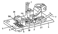
図1は本発明を実施する2本針型式の二重環縫いミシン全体の外観斜視図、図2は同2本針型式の二重環縫いミシンの要部を、針板の斜め前方から見た拡大斜視図、図3は同2本針型式の二重環縫いミシンの要部で、生地押えの一部を切り欠いた状態を針板の斜め前方から見た拡大斜視図、図4は同2本針型式の二重環縫いミシンにおける電気回路を含む概略のブロック構成図である。Hereinafter, embodiments of the present invention will be described with reference to the drawings.
FIG. 1 is a perspective view of the entire appearance of a two-needle type double chain stitch machine embodying the present invention. FIG. 2 is a perspective view of the main part of the two-needle type double chain stitch machine from an oblique front of a needle plate. 3 is an enlarged perspective view of the main part of the double-needle sewing machine of the two-needle type, and is an enlarged perspective view of a state in which a part of the fabric presser is cut away, as viewed obliquely from the front of the needle plate. FIG. It is a schematic block diagram including an electric circuit in the double-needle type double chain stitch sewing machine.
上記2本針型式の二重環縫いミシンMは、ミシン本体20の上部及び下部から左側方に向けてミシンアーム部21とミシンベッド部22とが互いに略平行に延設されている。ミシンアーム部21の内部には、ミシン主軸、縫製進行方向に対して略直交する方向に並列配置された左右2本の針1,1(図2、図3参照)を上下に往復運動させる針駆動機構、生地押え2(図2、図3等を参照)を上下に往復運動させる押え駆動機構、後述する生地送り装置の駆動機構やそれら各駆動機構への動力分配機構など後述するモータ23に連動連結された被動部3(図4参照)が組み込まれている。なお、前記各駆動機構や動力分配機構などの被動部3は二重環縫いミシンMにおいて周知であるため、それらの詳しい説明は省略する。 In the two-needle type double chain stitch sewing machine M, a sewing
前記ミシンベッド部22の上面には、前記針1,1が通過する針落ち部4Aを有する針板4が固定されており、該針板4の下部には、針板4上に載せ付けられた被縫製生地Wを所定の縫製進行方向Xに向けて間欠的に移送する生地送り装置として、前記針板4に形成された複数の長溝5内においてそれぞれ縫製進行方向X及び上下方向に循環往復運動する複数条の送り歯6が設けられている。 A needle plate 4 having a
前記生地押え2は、針板4上に載せ付けられた被縫製生地Wを前記針板4及び送り歯6側に押し付ける機能を有し、該生地押え2と針板4との間に被縫製生地Wが存在するか否かを検知する生地存否検知センサ24が前記針板4上に設置されている。 The
前記生地存否検知センサ24は、前記針板4を前記モータ23の電源25に電気的に接続(プラス接続)することで該針板4により形成される固定接点24aと、アース線7及びミシン本体20を介して接地接続(マイナス接続)されて前記固定接点24aに対して接離可能な可動接片24bとから構成される。この生地存否検知センサ24は、図4に示すように、前記電源25から前記モータ23への給電回路26に介在され、前記可動接片24bが固定接点24aに接触することで電磁開閉器28を介して前記給電回路26を開いてモータ23への給電を遮断しモータ23を作動停止しミシンMの前記被動部3の駆動を停止し、かつ、前記可動接片24bが固定接点24aから離間することで前記電磁開閉器28を介して前記給電回路26を閉じてモータ23へ給電してモータ23を作動可能とし、この状態で、動作スイッチとしてのフットペダル37を踏み込み操作することによりミシンMの前記被動部3を駆動する。 The cloth presence /
前記生地存否検知センサ24における可動接片24bは、図2及び図3に明示するように、縫製進行方向Xの前部がプラスチック等の電気絶縁材からなるセンサ取付台27を介して前記生地押え2にネジ止め固定され、該固定個所から縫製進行方向Xの上手側に向けた延出された板ばね部材28の自由端部に一連一体に形成されており、板ばね部材28により下向きに弾性付勢されている。この可動接片24bは、側面視で略半円状に形成されており、その略半円状可動接片24bの頂点が前記針落ち部4Aの直前で、かつ、前記複数条の送り歯6の送り幅内の中央に位置する細い針板桟部4aに対して接離するように配置され、この針板桟部4aが生地存否検知センサ24における固定接点24aを構成する。 As shown in FIGS. 2 and 3, the
なお、図中29は、前記生地存否検知センサ24における可動接片24bの固定接点24aに対する接離動作を案内するガイドであって、プラスチック等の電気絶縁材あるいはアルミニューム等の導電部材の表面に、例えばアルマイト処理などの電気絶縁処理を施したものから構成され、前記生地押え2の縫製進行方向Xの上手側端部にネジ止め固定されている。
また、図4に示すように、前記モータ23の作動を制御するコントローラ30内には、該モータ23の回転速度を変更可能な可変速部31と記憶部32と出力部33とが設けられている。前記コントローラ30は、被縫製生地Wの試縫い時において、被縫製生地Wの縫製長さや生地の種類等に対応して前記可変速部31を介して縫製対象となる被縫製生地Wの縫製進行方向終端部分の縫製時における回転速度が縫製進行方向始端部分の縫製時における回転速度よりも低速となる速度変更を行なうことによって前記被縫製生地Wに適応する速度変更履歴を学習し、その学習した速度変更履歴を回転数測定器34により計測して前記記憶部32に記憶しておき、本縫い時には前記記憶部32に記憶された前記被縫製生地Wに適応する速度変更履歴を読み出して前記出力部33から前記可変速部31に出力することにより、前記モータ23の回転速度を試縫い時の速度変更履歴に基づいて自動的に速度を調整するように構成されている。 As shown in FIG. 4, a
以上に説明した構成及び装置の他に、本実施の形態の2本針型式の二重環縫いミシンMは、図4に示すように、被動部3の一つとして縫製後の針糸を切断する糸切り装置35を備えている。この糸切り装置35には、該糸切り装置35を前記生地存否検知センサ24の検知動作後において糸切り作動させる状態と糸切り作動を停止した状態とに切替可能な糸切り作動・非作動切替スイッチ36が設けられており、縫製前にオペレータが前記スイッチ36を操作することにより、前記糸切り装置35を作動させる状態と作動させない状態とのいずれかを選択できるように構成されている。 In addition to the configuration and apparatus described above, the two-needle type double chain stitch sewing machine M of the present embodiment cuts the needle thread after sewing as one of the driven
次に、上記のように構成された本実施の形態に係る2本針型式の二重環縫いミシンMを用いて、被縫製生地の一例である図5に示すようなTシャツWの袖口Waを、筒状でなく平坦状に開いた状態で袖口端部分を適宜幅にわたり折り返し、その折り返し重ね合わせ袖口部分Wbを、図6に示すように、ヘム縫いすることで袖口を補強する場合の縫製動作について説明する。 Next, using the two-needle type double chain stitch sewing machine M according to the present embodiment configured as described above, the cuff Wa of the T-shirt W as shown in FIG. When the end portion of the cuff is folded back over an appropriate width in a state of being opened flat rather than in a cylindrical shape, and the folded cuff portion Wb is hem-stitched as shown in FIG. The operation will be described.
TシャツWの折り返し重ね合わせ袖口部分Wbを針板4上に載せ付けるとともに、フットペダル37の踏み返しにより生地押え2を上昇させて、折り返し重ね合わせ袖口部分Wbの縫い始め端部を生地押え2の下部に差し入れると、前記生地存否検知センサ24における可動接片24bが下向きの弾性付勢力に抗して上方に変位して固定接点24aから離間する。これに伴って、給電回路26が電磁開閉器28を介して閉じられて電源25からモータ23への給電が開始されて該モータ23が回転作動可能となる。この状態でフットペダル37を踏み込み操作することにより、モータ23が回転作動してミシン被動部3が駆動され、針1,1及び送り歯6等が所定通りに動作される。 The folded and overlapped cuff portion Wb of the T-shirt W is placed on the needle plate 4, and the
ミシン被動部3が駆動されることに伴い、複数条の送り歯6を介してTシャツWの折り返し重ね合わせ袖口部分Wbが縫製進行方向Xに間欠移送されながら、針1,1の上下運動し、これによって折り返し重ね合わせ袖口部分Wbが順次縫製(ヘム縫い)される。 As the sewing machine driven
そして、ヘム縫いが進行して前記折り返し重ね合わせ袖口部分Wbの終端(縫い終わり端)が針落ち部4Aの直前位置にまで移送されると、前記生地存否検知センサ24における可動接片24bが折り返し重ね合わせ袖口部分Wbから離脱して下方に弾性変位し、該可動接片24bの頂点が前記針落ち部4Aの直前に位置する細い針板桟部4a、即ち、生地存否検知センサ24における固定接点24aに接触する。これに伴って、前記給電回路26が電磁開閉器28を介して開かれて電源25からモータ23への給電が遮断されるので、フットペダル37を踏み込み操作したままの状態でありながらも該モータ23の回転作動が停止され、ミシン被動部3の駆動が停止される。 Then, when the hem stitching progresses and the terminal end (sewing end end) of the folded overlap cuff portion Wb is transferred to a position immediately before the
以上のように、ミシンMの駆動を停止するために生地存否検知センサ26のみを用い、かつ、この生地存否検知センサ26が、モータ23の電源25に電気的に接続される針板4の一部(針板桟部4a)から形成される固定接点24aとミシン本体20を介して接地接続され前記固定接点24aに対して切離可能な可動接片24bとから構成されるものであるから、冒述した従来の自動停止装置に比べて、ミシン駆動停止のための構成要素を大幅に削減して全体構造の簡素化、小型化が図れる。特に、回路構成の簡単化、低コスト化を図ることができる。 As described above, only the cloth presence / absence detection sensor 26 is used to stop the driving of the sewing machine M, and the cloth presence / absence detection sensor 26 is a part of the needle plate 4 electrically connected to the
その上、前記生地存否検知センサ26の可動接片24bが縫製進行方向Xにおいて針落ち部4Aの直前で、かつ、送り歯6による生地送り幅内の中央に配置されているので、モータ23への給電が遮断された後においてモータ23の慣性回転により折り返し重ね合わせ袖口部分Wbが縫製進行方向Xに多少移送されることがあっても、それは数針程度であり、折り返し重ね合わせ袖口部分Wbの縫い終わり端が針落ち部4A又はその極近傍位置に達した時点で生地送りを含めてミシンMの駆動を自動的かつ確実に停止することができる。それゆえ、図7に示すように、先行する折り返し重ね合わせ袖口部分Wbのヘム縫いが終了した後にフットペダル37を踏み返し操作して生地押え2を上昇させて、次のTシャツWの折り返し重ね合わせ袖口部分Wbを針板4上に載せ付けて該針板4と生地押え2との間に差し入れて連続的にヘム縫い行うことにより、先行する折り返し重ね合わせ袖口部分Wbの縫い終わり端と次に差し入れられる折り返し重ね合わせ袖口部分Wbの縫い始め端との間にほとんど余分な隙間を生じることがなくなる。したがって、図8に示すように、同一種類の複数枚のTシャツWの折り返し重ね合わせ袖口部分Wbを次々と連続的にヘム縫いした場合、隣接する生地間にそれぞれ余分な隙間を生じることがないため、全体として連続縫製作業の効率アップを図ることができる。 In addition, the
また、生地存否検知センサ26の可動接片24aが針落ち部4Aの直前で、かつ、送り歯6による生地送り幅内の中央に配置されているため、被縫製生地Wの縫い始め端、縫い終わり端が縫製進行方向に対して略直交しているときであっても、生地存否検知センサが生地押え2の側方に配置されている場合に比較して、縫目形成個所前後の検知が可能となるので、縫い始め端、縫い終わり端の形状いかんにかかわらず、検知精度の著しい向上を図ることができる。 In addition, since the
特に、同一種類、同一長さの複数枚のTシャツWの折り返し重ね合わせ袖口部分Wbを連続して縫製するにあたっては、事前に試縫いを行い、この試縫い時にコントローラ30内の可変速部31を介して縫製進行方向の終端部分の回転速度が縫製進行方向の始端部分の回転速度よりも低速となる条件を満たすように、縫製対象となる折り返し重ね合わせ袖口部分Wbのヘム縫いに適応する速度変更履歴を学習し、その学習した試縫い時の速度変更履歴を記憶部32に記憶しておく。そして、本縫い時に前記記憶部32からヘム縫いに適応する速度変更履歴を読み出して前記出力部33から前記可変速部31に出力することにより、前記モータ23の回転速度を試縫い時の速度変更履歴に基づいて、縫い始め部分は高速(例えば、最高回転速度)に、かつ、縫い終わり端部分では低速(例えば、最高回転速度の半分以下の回転速度)となるように自動的に調整することが可能である。これによって、全体としての縫製効率は高い状態に維持しながらも、モータ23の慣性回転による影響を最小限に止めて、縫い終わり端が針落ち部4A又はその極近傍位置からほとんどオーバーランしない位置に止まるようにミシンMの駆動を停止することができる。 In particular, when the folded and cuffed portions Wb of a plurality of T-shirts W of the same type and the same length are continuously sewn, trial sewing is performed in advance, and the
なお、上記実施の形態では、糸切り装置35を、縫製開始前にスイッチ36を介して非作動状態にして複数枚のTシャツWの袖口部分が針糸を介して連続一体化された状態にヘム縫いする場合について説明したが、該糸切り装置35を縫製開始時にスイッチ36を介して作動状態に切替えておくことにより、複数枚のTシャツWが個々に分断された縫製品を得ることが可能である。 In the above embodiment, the
また、上記実施の形態では、2本針型式の二重環縫いミシンに適用したが、これに限らず、2本針型式の平ベッド形二重環縫いミシンに適用しても、3本針以上の複数本針型式の平ベッド形二重環縫いミシンに適用してもよい。 Further, in the above embodiment, the present invention is applied to the double needle type double chain stitch sewing machine. However, the present invention is not limited to this. You may apply to the above flat needle type double chain stitch sewing machine of multiple needle type.
1,1 針
2 生地押え
4 針板
4A 針落ち部
6 送り歯(生地送り装置)
23 モータ
24 生地存否検知センサ
24a 固定接点
24b 可動接片
25 電源
26 給電回路
27 センサ取付台(電気絶縁体)
28 板ばね部材
31 可変速部
32 記憶部
33 出力部
35 糸切り装置
M 二重環縫いミシン
W Tシャツ(縫製生地)
X 縫製進行方向1,1
23
28
X Sewing progress direction
Claims (4)
前記生地存否検知センサは、前記電源に電気的に接続される前記針板により形成される固定接点と、ミシン本体を介して接地接続されて前記固定接点に対して接離可能な可動接片とから構成され、該可動接片が前記固定接点に接触することで前記給電回路を開いて前記モータへの給電を遮断してミシンの駆動を停止し、かつ、前記可動接片が前記固定接点から離間することで前記給電回路を閉じて前記モータへ給電してミシンの駆動を可能とするように構成されており、該生地存否検知センサにおける前記可動接片が、前記縫製進行方向において前記針落ち部の直前で、かつ、前記生地送り装置の送り幅内に配置されていることを特徴とする縫い終わり端検知自動停止装置付きミシン。A motor for driving the sewing machine, a needle that reciprocates up and down in conjunction with the operation of the motor, a needle plate having a needle drop portion through which the needle passes, and a lower portion of the needle plate provided on the needle plate A cloth feed device for transferring the cloth to be sewn in a predetermined sewing progress direction, a cloth presser for pressing the cloth to be sewn against the needle plate, and whether or not the cloth to be sewn exists on the needle plate. A sewing machine with a sewing end detection automatic stop device comprising a cloth presence / absence detection sensor to detect,
The cloth presence / absence detection sensor includes a fixed contact formed by the needle plate electrically connected to the power source, and a movable contact piece that is grounded via a sewing machine body and is capable of contacting and leaving the fixed contact. The movable contact piece is brought into contact with the fixed contact, thereby opening the power supply circuit to cut off the power supply to the motor and stopping the driving of the sewing machine, and the movable contact piece from the fixed contact. By separating the power supply circuit, the power supply circuit is closed to supply power to the motor so that the sewing machine can be driven, and the movable contact piece in the cloth presence / absence detection sensor is connected to the needle drop in the sewing progress direction. A sewing machine with an automatic stop device for detecting the end of sewing, which is disposed immediately before the portion and within the feed width of the cloth feed device.
Priority Applications (3)
| Application Number | Priority Date | Filing Date | Title |
|---|---|---|---|
| JP2016086559A JP6861934B2 (en) | 2016-04-05 | 2016-04-05 | Sewing machine with automatic stop device for detecting the end of sewing |
| TW106111114A TWI738755B (en) | 2016-04-05 | 2017-03-31 | Sewing machine with automatic stop device for detecting end of stitching |
| CN201710217093.7A CN107268197B (en) | 2016-04-05 | 2017-04-05 | Sewing machine with sewing terminal detection automatic stop device |
Applications Claiming Priority (1)
| Application Number | Priority Date | Filing Date | Title |
|---|---|---|---|
| JP2016086559A JP6861934B2 (en) | 2016-04-05 | 2016-04-05 | Sewing machine with automatic stop device for detecting the end of sewing |
Publications (2)
| Publication Number | Publication Date |
|---|---|
| JP2017185177A true JP2017185177A (en) | 2017-10-12 |
| JP6861934B2 JP6861934B2 (en) | 2021-04-21 |
Family
ID=60045953
Family Applications (1)
| Application Number | Title | Priority Date | Filing Date |
|---|---|---|---|
| JP2016086559A Active JP6861934B2 (en) | 2016-04-05 | 2016-04-05 | Sewing machine with automatic stop device for detecting the end of sewing |
Country Status (3)
| Country | Link |
|---|---|
| JP (1) | JP6861934B2 (en) |
| CN (1) | CN107268197B (en) |
| TW (1) | TWI738755B (en) |
Cited By (1)
| Publication number | Priority date | Publication date | Assignee | Title |
|---|---|---|---|---|
| CN112011909A (en) * | 2019-05-31 | 2020-12-01 | 浙江中捷缝纫科技有限公司 | Sewing machine system, control method and device of sewing machine system |
Families Citing this family (2)
| Publication number | Priority date | Publication date | Assignee | Title |
|---|---|---|---|---|
| CN108414519B (en) * | 2018-02-11 | 2021-01-26 | 常熟理工学院 | Detection apparatus for select syringe needle position of needle ware |
| JP2020142041A (en) * | 2019-03-07 | 2020-09-10 | ヤマトミシン製造株式会社 | Round fabric hem sewing machine |
Family Cites Families (13)
| Publication number | Priority date | Publication date | Assignee | Title |
|---|---|---|---|---|
| JPS494685B1 (en) * | 1968-05-13 | 1974-02-02 | ||
| JPS4717584U (en) * | 1971-03-27 | 1972-10-28 | ||
| JPS5933348Y2 (en) * | 1975-11-28 | 1984-09-17 | 蛇の目ミシン工業株式会社 | Control device for single stitch sewing machine |
| JPS56116489A (en) * | 1980-02-14 | 1981-09-12 | Mitsubishi Electric Corp | Stitching apparatus |
| JPS60172437U (en) * | 1984-04-23 | 1985-11-15 | 三菱電機株式会社 | Transistor base drive circuit |
| JPH0243351Y2 (en) * | 1985-11-08 | 1990-11-19 | ||
| JPS62277993A (en) * | 1986-05-26 | 1987-12-02 | ジューキ株式会社 | Cloth end detector of sewing machine |
| JPH04240479A (en) * | 1991-01-23 | 1992-08-27 | Mitsubishi Electric Corp | Sewing maching controller |
| JP2640307B2 (en) * | 1992-07-17 | 1997-08-13 | ヤマトミシン製造株式会社 | Reverse stitching method and apparatus for flat stitch sewing machine |
| WO1999043882A1 (en) * | 1998-02-27 | 1999-09-02 | Mitsubishi Denki Kabushiki Kaisha | Sewing machine controller |
| JP4022790B2 (en) | 1998-06-26 | 2007-12-19 | 富士通株式会社 | Insulating film and method for forming the same |
| JP2001046773A (en) * | 1999-08-10 | 2001-02-20 | Juki Corp | Control device of sewing machine motor |
| JP6278878B2 (en) | 2014-10-27 | 2018-02-14 | 東京瓦斯株式会社 | Wearable environment improvement device and specific gas alarm |
-
2016
- 2016-04-05 JP JP2016086559A patent/JP6861934B2/en active Active
-
2017
- 2017-03-31 TW TW106111114A patent/TWI738755B/en active
- 2017-04-05 CN CN201710217093.7A patent/CN107268197B/en active Active
Cited By (1)
| Publication number | Priority date | Publication date | Assignee | Title |
|---|---|---|---|---|
| CN112011909A (en) * | 2019-05-31 | 2020-12-01 | 浙江中捷缝纫科技有限公司 | Sewing machine system, control method and device of sewing machine system |
Also Published As
| Publication number | Publication date |
|---|---|
| TWI738755B (en) | 2021-09-11 |
| CN107268197B (en) | 2021-06-11 |
| JP6861934B2 (en) | 2021-04-21 |
| TW201742965A (en) | 2017-12-16 |
| CN107268197A (en) | 2017-10-20 |
Similar Documents
| Publication | Publication Date | Title |
|---|---|---|
| TWI402390B (en) | Sewing machine | |
| JP6560913B2 (en) | sewing machine | |
| JP2017185177A (en) | Sewing machine with sewing termination end detecting automatic stopping device | |
| JP4960008B2 (en) | Sewing sewing machine | |
| JP6441221B2 (en) | sewing machine | |
| TWI703250B (en) | Sewing machine, sewing device, and sewing method | |
| JP4070164B2 (en) | Belt loop sewing machine | |
| JP3897641B2 (en) | sewing machine | |
| JP6425069B2 (en) | sewing machine | |
| JP4030864B2 (en) | Upper thread holding device for sewing machine | |
| JP2009050638A (en) | Sewing machine | |
| CN109267252A (en) | Cutting facility and method on a kind of sewing machine for continuously sewing | |
| JP3804034B2 (en) | Tape material feeder | |
| JP4336419B2 (en) | Belt loop sewing machine | |
| JP2762720B2 (en) | Sewing machine with button | |
| JP2001096084A (en) | Sewing machine for darning hole | |
| JP6374745B2 (en) | sewing machine | |
| JPS6043993B2 (en) | sewing machine sewing device | |
| US20130247805A1 (en) | Upper feed device and sewing machine | |
| JP2010035672A (en) | Welting machine | |
| CN105734852B (en) | The control method of sewing machine and sewing machine | |
| JPS62614Y2 (en) | ||
| CN115506088A (en) | Single-needle and double-needle switchable sewing machine and control method thereof | |
| JPS5850987A (en) | Method and apparatus for preventing loosening of stitch terminal of sewing machine | |
| JPS5910824B2 (en) | Sewing machine cloth control device |
Legal Events
| Date | Code | Title | Description |
|---|---|---|---|
| A621 | Written request for application examination |
Free format text: JAPANESE INTERMEDIATE CODE: A621 Effective date: 20190320 |
|
| A977 | Report on retrieval |
Free format text: JAPANESE INTERMEDIATE CODE: A971007 Effective date: 20191219 |
|
| A131 | Notification of reasons for refusal |
Free format text: JAPANESE INTERMEDIATE CODE: A131 Effective date: 20200107 |
|
| A521 | Written amendment |
Free format text: JAPANESE INTERMEDIATE CODE: A523 Effective date: 20200225 |
|
| A131 | Notification of reasons for refusal |
Free format text: JAPANESE INTERMEDIATE CODE: A131 Effective date: 20200630 |
|
| A521 | Written amendment |
Free format text: JAPANESE INTERMEDIATE CODE: A523 Effective date: 20200819 |
|
| TRDD | Decision of grant or rejection written | ||
| A01 | Written decision to grant a patent or to grant a registration (utility model) |
Free format text: JAPANESE INTERMEDIATE CODE: A01 Effective date: 20210126 |
|
| A61 | First payment of annual fees (during grant procedure) |
Free format text: JAPANESE INTERMEDIATE CODE: A61 Effective date: 20210216 |
|
| R150 | Certificate of patent or registration of utility model |
Ref document number: 6861934 Country of ref document: JP Free format text: JAPANESE INTERMEDIATE CODE: R150 |