JP2017181527A - Developing cartridge - Google Patents
Developing cartridge Download PDFInfo
- Publication number
- JP2017181527A JP2017181527A JP2016062964A JP2016062964A JP2017181527A JP 2017181527 A JP2017181527 A JP 2017181527A JP 2016062964 A JP2016062964 A JP 2016062964A JP 2016062964 A JP2016062964 A JP 2016062964A JP 2017181527 A JP2017181527 A JP 2017181527A
- Authority
- JP
- Japan
- Prior art keywords
- gear
- protrusion
- axial direction
- developing cartridge
- moving member
- Prior art date
- Legal status (The legal status is an assumption and is not a legal conclusion. Google has not performed a legal analysis and makes no representation as to the accuracy of the status listed.)
- Pending
Links
Images


Classifications
-
- G—PHYSICS
- G03—PHOTOGRAPHY; CINEMATOGRAPHY; ANALOGOUS TECHNIQUES USING WAVES OTHER THAN OPTICAL WAVES; ELECTROGRAPHY; HOLOGRAPHY
- G03G—ELECTROGRAPHY; ELECTROPHOTOGRAPHY; MAGNETOGRAPHY
- G03G21/00—Arrangements not provided for by groups G03G13/00 - G03G19/00, e.g. cleaning, elimination of residual charge
- G03G21/16—Mechanical means for facilitating the maintenance of the apparatus, e.g. modular arrangements
- G03G21/18—Mechanical means for facilitating the maintenance of the apparatus, e.g. modular arrangements using a processing cartridge, whereby the process cartridge comprises at least two image processing means in a single unit
- G03G21/1839—Means for handling the process cartridge in the apparatus body
- G03G21/1857—Means for handling the process cartridge in the apparatus body for transmitting mechanical drive power to the process cartridge, drive mechanisms, gears, couplings, braking mechanisms
-
- G—PHYSICS
- G03—PHOTOGRAPHY; CINEMATOGRAPHY; ANALOGOUS TECHNIQUES USING WAVES OTHER THAN OPTICAL WAVES; ELECTROGRAPHY; HOLOGRAPHY
- G03G—ELECTROGRAPHY; ELECTROPHOTOGRAPHY; MAGNETOGRAPHY
- G03G21/00—Arrangements not provided for by groups G03G13/00 - G03G19/00, e.g. cleaning, elimination of residual charge
- G03G21/16—Mechanical means for facilitating the maintenance of the apparatus, e.g. modular arrangements
- G03G21/1642—Mechanical means for facilitating the maintenance of the apparatus, e.g. modular arrangements for connecting the different parts of the apparatus
- G03G21/1647—Mechanical connection means
-
- G—PHYSICS
- G03—PHOTOGRAPHY; CINEMATOGRAPHY; ANALOGOUS TECHNIQUES USING WAVES OTHER THAN OPTICAL WAVES; ELECTROGRAPHY; HOLOGRAPHY
- G03G—ELECTROGRAPHY; ELECTROPHOTOGRAPHY; MAGNETOGRAPHY
- G03G15/00—Apparatus for electrographic processes using a charge pattern
- G03G15/06—Apparatus for electrographic processes using a charge pattern for developing
- G03G15/08—Apparatus for electrographic processes using a charge pattern for developing using a solid developer, e.g. powder developer
- G03G15/0822—Arrangements for preparing, mixing, supplying or dispensing developer
- G03G15/0865—Arrangements for supplying new developer
- G03G15/0867—Arrangements for supplying new developer cylindrical developer cartridges, e.g. toner bottles for the developer replenishing opening
-
- G—PHYSICS
- G03—PHOTOGRAPHY; CINEMATOGRAPHY; ANALOGOUS TECHNIQUES USING WAVES OTHER THAN OPTICAL WAVES; ELECTROGRAPHY; HOLOGRAPHY
- G03G—ELECTROGRAPHY; ELECTROPHOTOGRAPHY; MAGNETOGRAPHY
- G03G15/00—Apparatus for electrographic processes using a charge pattern
- G03G15/06—Apparatus for electrographic processes using a charge pattern for developing
- G03G15/08—Apparatus for electrographic processes using a charge pattern for developing using a solid developer, e.g. powder developer
- G03G15/0822—Arrangements for preparing, mixing, supplying or dispensing developer
- G03G15/0887—Arrangements for conveying and conditioning developer in the developing unit, e.g. agitating, removing impurities or humidity
- G03G15/0889—Arrangements for conveying and conditioning developer in the developing unit, e.g. agitating, removing impurities or humidity for agitation or stirring
-
- G—PHYSICS
- G03—PHOTOGRAPHY; CINEMATOGRAPHY; ANALOGOUS TECHNIQUES USING WAVES OTHER THAN OPTICAL WAVES; ELECTROGRAPHY; HOLOGRAPHY
- G03G—ELECTROGRAPHY; ELECTROPHOTOGRAPHY; MAGNETOGRAPHY
- G03G15/00—Apparatus for electrographic processes using a charge pattern
- G03G15/75—Details relating to xerographic drum, band or plate, e.g. replacing, testing
- G03G15/757—Drive mechanisms for photosensitive medium, e.g. gears
-
- G—PHYSICS
- G03—PHOTOGRAPHY; CINEMATOGRAPHY; ANALOGOUS TECHNIQUES USING WAVES OTHER THAN OPTICAL WAVES; ELECTROGRAPHY; HOLOGRAPHY
- G03G—ELECTROGRAPHY; ELECTROPHOTOGRAPHY; MAGNETOGRAPHY
- G03G21/00—Arrangements not provided for by groups G03G13/00 - G03G19/00, e.g. cleaning, elimination of residual charge
- G03G21/16—Mechanical means for facilitating the maintenance of the apparatus, e.g. modular arrangements
- G03G21/1661—Mechanical means for facilitating the maintenance of the apparatus, e.g. modular arrangements means for handling parts of the apparatus in the apparatus
- G03G21/1676—Mechanical means for facilitating the maintenance of the apparatus, e.g. modular arrangements means for handling parts of the apparatus in the apparatus for the developer unit
-
- G—PHYSICS
- G03—PHOTOGRAPHY; CINEMATOGRAPHY; ANALOGOUS TECHNIQUES USING WAVES OTHER THAN OPTICAL WAVES; ELECTROGRAPHY; HOLOGRAPHY
- G03G—ELECTROGRAPHY; ELECTROPHOTOGRAPHY; MAGNETOGRAPHY
- G03G21/00—Arrangements not provided for by groups G03G13/00 - G03G19/00, e.g. cleaning, elimination of residual charge
- G03G21/16—Mechanical means for facilitating the maintenance of the apparatus, e.g. modular arrangements
- G03G21/18—Mechanical means for facilitating the maintenance of the apparatus, e.g. modular arrangements using a processing cartridge, whereby the process cartridge comprises at least two image processing means in a single unit
- G03G21/1839—Means for handling the process cartridge in the apparatus body
- G03G21/1857—Means for handling the process cartridge in the apparatus body for transmitting mechanical drive power to the process cartridge, drive mechanisms, gears, couplings, braking mechanisms
- G03G21/186—Axial couplings
-
- G—PHYSICS
- G03—PHOTOGRAPHY; CINEMATOGRAPHY; ANALOGOUS TECHNIQUES USING WAVES OTHER THAN OPTICAL WAVES; ELECTROGRAPHY; HOLOGRAPHY
- G03G—ELECTROGRAPHY; ELECTROPHOTOGRAPHY; MAGNETOGRAPHY
- G03G21/00—Arrangements not provided for by groups G03G13/00 - G03G19/00, e.g. cleaning, elimination of residual charge
- G03G21/16—Mechanical means for facilitating the maintenance of the apparatus, e.g. modular arrangements
- G03G21/18—Mechanical means for facilitating the maintenance of the apparatus, e.g. modular arrangements using a processing cartridge, whereby the process cartridge comprises at least two image processing means in a single unit
- G03G21/1875—Mechanical means for facilitating the maintenance of the apparatus, e.g. modular arrangements using a processing cartridge, whereby the process cartridge comprises at least two image processing means in a single unit provided with identifying means or means for storing process- or use parameters, e.g. lifetime of the cartridge
- G03G21/1896—Mechanical means for facilitating the maintenance of the apparatus, e.g. modular arrangements using a processing cartridge, whereby the process cartridge comprises at least two image processing means in a single unit provided with identifying means or means for storing process- or use parameters, e.g. lifetime of the cartridge mechanical or optical identification means, e.g. protrusions, bar codes
Abstract
Description
本発明は、現像カートリッジに関する。 The present invention relates to a developing cartridge.
従来、レーザプリンタなどの画像形成装置に現像カートリッジを着脱可能とした構造が知られている。現像カートリッジは、現像剤であるトナーを収容する。このような画像形成装置は、現像カートリッジ内のトナーの量が少なくなったかどうか、または、印刷枚数が予め設定された枚数を超えたかどうかを判定する。そして、画像形成装置が、現像カートリッジ内のトナーの量が少なくなった、または、印刷枚数が予め設定された枚数を超えたと判定すると、画像形成装置は、画像形成装置が備えるディスプレイに、現像カートリッジの交換を促す情報を表示する。ユーザは、ディスプレイに表示された情報を見ると、画像形成装置から現像カートリッジを取り出し、新たな現像カートリッジを画像形成装置に装着する。 Conventionally, a structure in which a developing cartridge can be attached to and detached from an image forming apparatus such as a laser printer is known. The developing cartridge contains toner that is a developer. Such an image forming apparatus determines whether the amount of toner in the developing cartridge has decreased or whether the number of printed sheets has exceeded a preset number. When the image forming apparatus determines that the amount of toner in the developing cartridge has decreased or the number of printed sheets has exceeded a preset number, the image forming apparatus displays the developing cartridge on the display included in the image forming apparatus. Displays information prompting for replacement. When viewing the information displayed on the display, the user takes out the developing cartridge from the image forming apparatus and attaches a new developing cartridge to the image forming apparatus.
カートリッジ交換式の従来の画像形成装置については、例えば、特許文献1に記載されている。 For example, Japanese Patent Application Laid-Open No. 2004-151867 describes a conventional image exchange apparatus of a cartridge exchange type.
また、従来、新品検知のための機構部を有する現像カートリッジが知られている。現像カートリッジの交換が行われると、画像形成装置は、新品検知のための機構部の動作を利用して、交換後の現像カートリッジが新品であるか否かを検知する。新品検知のための機構部は、当該機構部へ動力を伝達するためのギアとの不要な接触を避けながら、コンパクトに配置する必要がある。 Conventionally, a developing cartridge having a mechanism for detecting a new article is known. When the developing cartridge is replaced, the image forming apparatus detects whether the replaced developing cartridge is a new one by using the operation of the mechanism for detecting a new article. The mechanism part for detecting a new article needs to be arranged compactly while avoiding unnecessary contact with a gear for transmitting power to the mechanism part.
本発明の目的は、現像カートリッジにおいて、動力を伝達するためのギアとの不要な接触を避けつつ、現像カートリッジに関する情報を検知できる新たな構造を提供することを目的とする。 An object of the present invention is to provide a new structure capable of detecting information related to a developing cartridge while avoiding unnecessary contact with a gear for transmitting power in the developing cartridge.
上記課題を解決するため、本願の第1発明は、現像カートリッジであって、現像剤を収容可能な筐体と、前記筐体の外面に位置し、軸方向に延びる第1軸について回転可能な小径ギアであって、前記小径ギアの周囲の少なくとも一部分に沿って設けられた第1係合部を有する小径ギアと、前記外面に位置し、前記第1軸について前記小径ギアと共に回転可能な大径ギアであって、前記軸方向において、前記外面から前記小径ギアよりも離れて位置する大径ギアと、前記外面に位置し、前記第1軸とは異なる第2軸であって前記軸方向に延びる第2軸について、少なくとも第1位置から第2位置へ回転可能な第1ギアであって、前記第1ギアの周囲の少なくとも一部分に沿って設けられた第2係合部であって前記第1係合部の少なくとも一部と係合する第2係合部と、前記軸方向において前記外面と向かい合う第1端面と、前記軸方向において前記第1端面と反対の第2端面であり、前記軸方向において前記大径ギアと間隔を空けて離れ、前記大径ギアよりも前記外面に対して近くに位置する第2端面であって、前記第2端面の一部と、前記大径ギアの一部とが、前記軸方向に向かい合う第2端面と、前記第2端面に位置する1つ以上の突起であって、前記第1ギアと共に回転し、前記突起の先端部と、前記大径ギアとが前記軸方向において離れ、前記第1ギアが前記第1位置から前記第2位置へ回転する間に、前記突起の回転軌跡の一部と前記大径ギアの一部とが軸方向に重なる突起と、を有する第1ギアと、前記筐体に対して第3位置と第4位置との間で移動可能な移動部材であって、前記移動部材の少なくとも一部が、前記大径ギアよりも、前記筐体の外面に対して遠くに位置する移動部材と、を備え、前記移動部材は、前記大径ギアの回転軌跡の外側に位置し、前記第1ギアが前記第1位置から前記第2位置へ回転するときに、前記突起と接触可能な接触部であって、前記突起と接触することで前記移動部材を前記第3位置から前記第4位置へ移動させる接触部を有することを特徴とする。 In order to solve the above-mentioned problems, a first invention of the present application is a developing cartridge, and is rotatable about a housing capable of containing a developer and a first shaft that is located on an outer surface of the housing and extends in the axial direction. A small-diameter gear having a first engagement portion provided along at least a part of the periphery of the small-diameter gear, and a large-diameter gear positioned on the outer surface and rotatable with the small-diameter gear about the first shaft. A radial gear, a large-diameter gear positioned away from the small-diameter gear from the outer surface in the axial direction, and a second shaft positioned on the outer surface and different from the first shaft in the axial direction. A second gear extending at least from a first position to a second position, and a second engagement portion provided along at least a portion of the periphery of the first gear, At least a portion of the first engaging portion; And a second end face that faces the outer surface in the axial direction, and a second end face that is opposite to the first end face in the axial direction, and is spaced from the large-diameter gear in the axial direction. A second end face that is spaced apart and located closer to the outer surface than the large-diameter gear, wherein a part of the second end face and a part of the large-diameter gear face each other in the axial direction. A second end face and one or more protrusions positioned on the second end face, wherein the protrusion rotates with the first gear, and the tip end portion of the protrusion and the large-diameter gear are separated in the axial direction; A first gear having a protrusion in which a part of a rotation locus of the protrusion and a part of the large-diameter gear overlap in the axial direction while one gear rotates from the first position to the second position; A moving member movable between a third position and a fourth position with respect to the housing; And at least a part of the moving member includes a moving member positioned farther from the outer surface of the housing than the large-diameter gear, and the moving member has a rotational locus of the large-diameter gear. A contact portion that is located on the outer side and is capable of contacting the protrusion when the first gear rotates from the first position to the second position; It has a contact part moved from 3 positions to the 4th position, It is characterized by the above-mentioned.
本願の第2発明は、第1発明の現像カートリッジであって、前記第1ギアは、複数の前記突起を有し、複数の前記突起は、前記第1ギアの回転方向において互いに離れていることを特徴とする。 A second invention of the present application is the developing cartridge according to the first invention, wherein the first gear has a plurality of protrusions, and the plurality of protrusions are separated from each other in the rotation direction of the first gear. It is characterized by.
本願の第3発明は、第1発明または第2発明の現像カートリッジであって、前記第1ギアの少なくとも一部分を覆うギアカバーをさらに有し、前記ギアカバーが、前記移動部材を移動可能に支持することを特徴とする。 A third invention of the present application is the developing cartridge according to the first or second invention, further comprising a gear cover that covers at least a part of the first gear, and the gear cover movably supports the moving member. It is characterized by doing.
本願の第4発明は、第1発明から第3発明のいずれか1発明の現像カートリッジであって、前記移動部材を前記第4位置から前記第3位置に戻すための弾性力を発生させる弾性部材をさらに備えることを特徴とする。 A fourth invention of the present application is the developing cartridge according to any one of the first to third inventions, wherein the elastic member generates an elastic force for returning the moving member from the fourth position to the third position. Is further provided.
本願の第5発明は、第1発明から第4発明のいずれか1発明の現像カートリッジであって、前記移動部材は、前記軸方向に対して交差する方向に移動可能であることを特徴とする。 A fifth invention of the present application is the developing cartridge according to any one of the first to fourth inventions, wherein the moving member is movable in a direction crossing the axial direction. .
本願の第1発明〜第5発明によれば、移動部材の動きを利用して、現像カートリッジに関する情報を検知できる。また、大径ギア、突起、および移動部材を、大径ギアを避けつつコンパクトに配置できる。 According to the first to fifth aspects of the present application, information relating to the developing cartridge can be detected by using the movement of the moving member. In addition, the large-diameter gear, the protrusion, and the moving member can be arranged in a compact manner while avoiding the large-diameter gear.
また、本願の第2発明によれば、複数の突起によって、移動部材を複数回移動させることができる。 According to the second invention of the present application, the moving member can be moved a plurality of times by the plurality of protrusions.
また、本願の第4発明によれば、突起と接触部との接触が外れたときに、弾性部材の弾性力によって、移動部材を第3位置に戻すことができる。 According to the fourth invention of the present application, when the contact between the protrusion and the contact portion is released, the moving member can be returned to the third position by the elastic force of the elastic member.
以下、本発明の好適な実施形態について、図面を参照しつつ説明する。 Hereinafter, preferred embodiments of the present invention will be described with reference to the drawings.
なお、以下の実施形態では、検知ギア(第1ギア)の回転軸である第1軸が延びる方向を「軸方向」と称する。本願の図1、図2、および図4には、軸方向が矢印で示されている。 In the following embodiments, the direction in which the first axis that is the rotation axis of the detection gear (first gear) extends is referred to as “axial direction”. 1, 2, and 4 of the present application, the axial direction is indicated by an arrow.
<1.現像カートリッジの全体構成>
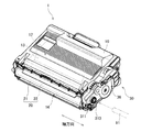
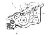
図1は、本発明の一例となる現像カートリッジ1の斜視図である。この現像カートリッジ1は、電子写真方式の画像形成装置(例えば、レーザプリンタやLEDプリンタ)に装着されて、現像剤であるトナーを感光ドラムへ供給するユニットである。図1に示すように、現像カートリッジ1は、ケーシング10、現像ローラ20、およびギア部30を有する。
<1. Overall configuration of developer cartridge>
FIG. 1 is a perspective view of a developing
ケーシング10は、電子写真印刷用のトナーを収容可能な筐体である。ケーシング10は、ギア部30が配置される第1外面11(図2参照)と、その反対側に位置する第2外面とを有する。ケーシング10は、第1外面11と第2外面との間で、軸方向に直方体状に延びている。ケーシング10の内部には、トナーを収容するトナー室12が、設けられている。また、ケーシング10は、トナー室12内に軸方向に延びるアジテータ13を有する。アジテータ13は、後述するアジテータギア34に連結され、アジテータギア34と共に回転する。アジテータ13が回転すると、トナー室12内のトナーが撹拌される。これにより、トナーの凝集が抑制される。
The
現像ローラ20は、軸方向に延びる回転軸について回転可能なローラである。本実施形態の現像ローラ20は、ローラ本体21とローラシャフト22とを有する。ローラ本体21は、軸方向に延びる円筒状の部材である。ローラ本体21の材料には、例えば、弾性を有するゴムが用いられる。ローラシャフト22は、ローラ本体21を軸方向に貫通する略円柱状の部材である。ローラシャフト22の材料には、導電性を有する金属または樹脂が用いられる。ローラ本体21は、ローラシャフト22に対して、相対回転不能に接続される。したがって、ローラシャフト22が回転すると、ローラシャフト22と共にローラ本体21も回転する。
The developing
なお、ローラシャフト22は、ローラ本体21を軸方向に貫通していなくてもよい。例えば、一対のローラシャフト22が、ローラ本体21の軸方向の両端から、軸方向にそれぞれ延びていてもよい。
The
ケーシング10は、トナー室12と外部とを連通する開口部14を有する。現像ローラ20のローラ本体21は、開口部14に、軸方向に沿って配置される。ローラシャフト22の軸方向の一方の端部は、後述する現像ギア32に連結される。ローラシャフト22は、現像ギア32に対して、相対回転不能に接続される。すなわち、ローラシャフト22は、現像ギア32と共に回転可能である。このため、現像ギア32が回転すると、ローラシャフト22が回転し、ローラシャフト22と共に現像ローラ20も回転する。
The
画像形成装置の稼働時には、ケーシング10内のトナー室12から、図示を省略した供給ローラを介して、現像ローラ20の外周面に、トナーが供給される。その際、供給ローラと現像ローラ20との間において、トナーは摩擦帯電される。一方、現像ローラ20のローラシャフト22には、バイアス電圧がかけられている。このため、ローラシャフト22とトナーとの間の静電気力によって、ローラ本体21の外周面に、トナーが引き付けられる。
During operation of the image forming apparatus, toner is supplied from the
また、現像カートリッジ1は、図示を省略した層厚規制ブレードを有する。層厚規制ブレードは、ローラ本体21の外周面に供給された余分なトナーを削ぎ落とす。これにより、層厚規制ブレードを通過したローラ本体21の表面に、トナーが一定の厚みで担持される。その後、ローラ本体21の外周面に担持されたトナーは、画像形成装置側の感光ドラムへ供給される。このとき、トナーは、感光ドラムの外周面に形成された静電潜像に応じて、ローラ本体21から感光ドラムへ移動する。これにより、感光ドラムの外周面において、静電潜像が可視像化される。
Further, the developing
ギア部30は、ケーシング10の第1外面11に位置する。ギア部30は、複数のギアと、複数のギアの少なくとも一部を覆うギアカバー36とを有する。ギア部30の複数のギアは、後述するカップリング部311を含む。画像形成装置に現像カートリッジ1が装着されたときには、画像形成装置の駆動シャフト91がカップリング部311に連結される。そして、駆動シャフト91から供給される動力が、ギア部30内の複数のギアを介して、アジテータ13や現像ローラ20に伝達される。
The
<2.ギア部の構造>
続いて、ギア部30の構造について、説明する。
<2. Gear structure>
Then, the structure of the
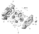
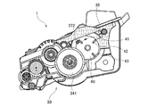
図2は、ギア部30の分解斜視図である。図1および図2に示すように、本実施形態のギア部30は、カップリング31、現像ギア32、アイドルギア33、アジテータギア34、検知ギア35、ギアカバー36、および移動部材37を有する。カップリング31、現像ギア32、アイドルギア33、アジテータギア34、および検知ギア35は、いずれも、軸方向に延びる回転軸を中心として回転する。
FIG. 2 is an exploded perspective view of the
なお、図2では、アジテータギア34の小径ギア342および検知ギア35以外のギアについては、ギア歯の図示が省略されている。
In FIG. 2, the gear teeth of the
カップリング31は、画像形成装置から供給される駆動力を、最初に受けるギアである。カップリング31は、軸方向に延びる回転軸A1について回転可能である。カップリング31は、カップリング部311とカップリングギア312とを有する。カップリング部311およびカップリングギア312は、例えば、樹脂により一体に形成される。カップリング部311には、軸方向に凹む締結穴313が設けられている。カップリングギア312の外周部には、全周に亘って等間隔に複数のギア歯が設けられている。
The
画像形成装置に現像カートリッジ1が装着されると、図1中に二点鎖線で示すように、画像形成装置の駆動シャフト91が、カップリング部311の締結穴313に挿入される。これにより、駆動シャフト91とカップリング部311とが、相対回転不能に接続される。したがって、駆動シャフト91が回転すると、カップリング部311が回転し、カップリング部311と共にカップリングギア312も回転する。
When the developing
現像ギア32は、現像ローラ20を回転させるためのギアである。現像ギア32は、軸方向に延びる回転軸A2について回転可能である。現像ギア32の外周部には、全周に亘って等間隔に複数のギア歯が設けられている。カップリングギア312のギア歯と、現像ギア32のギア歯とは、互いに噛み合っている。また、現像ギア32は、現像ローラ20のローラシャフト22の軸方向における一方の端部に、相対回転不能に接続されている。すなわち、現像ローラ20のローラシャフト22は、現像ギア32と共に回転可能である。このため、カップリングギア312が回転すると、現像ギア32が回転し、現像ギア32と共に現像ローラ20も回転する。
The developing
アイドルギア33は、カップリングギア312の回転をアジテータギア34に伝達するためギアである。アイドルギア33は、軸方向に延びる回転軸A3について回転可能である。アイドルギア33は、第3軸に沿って配列された入力ギア331および出力ギア332を有する。入力ギア331および出力ギア332は、例えば、樹脂により一体に形成される。ケーシング10の第1外面11から出力ギア332までの軸方向の距離は、ケーシング10の第1外面11から入力ギア331までの軸方向の距離よりも、大きい。また、出力ギア332の径は、入力ギア331の径よりも小さい。
The
入力ギア331および出力ギア332の外周部には、それぞれ、全周に亘って等間隔に複数のギア歯が設けられている。カップリングギア312のギア歯と、入力ギア331のギア歯とは、互いに噛み合っている。また、出力ギア332のギア歯と、アジテータギア34の後述する大径ギア341のギア歯とは、互いに噛み合っている。カップリングギア312が回転すると、入力ギア331が回転し、入力ギア331と共に出力ギア332も回転する。そして、出力ギア332の回転に伴い、アジテータギア34も回転する。
A plurality of gear teeth are provided on the outer peripheral portions of the
アジテータギア34は、トナー室12内のアジテータ13を回転させるためのギアである。アジテータギア34は、軸方向に延びる回転軸(第1軸)A4について回転可能である。アジテータギア34は、第1軸A4に沿って配列された大径ギア341および小径ギア342を有する。大径ギア341および小径ギア342は、例えば、樹脂により一体に形成される。小径ギア342の径は、大径ギア341の径よりも小さい。また、大径ギア341は、軸方向において、ケーシング10の第1外面11から小径ギア342よりも離れて位置する。すなわち、ケーシング10の第1外面11から小径ギア342までの軸方向の距離は、ケーシング10の第1外面11から大径ギア341までの軸方向の距離よりも、小さい。
The
大径ギア341および小径ギア342の外周部には、それぞれ、全周に亘って等間隔に複数のギア歯が設けられている。上述の通り、アイドルギア33の出力ギア332のギア歯と、アジテータギア34の大径ギア341のギア歯とは、互いに噛み合っている。また、アジテータギア34は、アジテータ13の軸方向における一方の端部に対して、相対回転不能に接続されている。すなわち、アジテータ13は、アジテータギア34とともに回転可能である。このため、カップリング31からアイドルギア33を介してアジテータギア34に動力が伝達されると、大径ギア341が回転し、大径ギア341と共に小径ギア342も回転する。そして、アジテータギア34の回転に伴い、アジテータ13も回転する。
A plurality of gear teeth are provided on the outer peripheral portions of the large-
検知ギア35は、画像形成装置に対して現像カートリッジ1の仕様などの必要な情報を伝達するためのギアである。検知ギア35は、本発明における第1ギアの一例である。検知ギア35は、軸方向に延びる回転軸(第2軸)A5について回転可能である。第1軸A4と第2軸A5とは、異なる位置において互いに平行に延びる。検知ギア35は、外周部の一部分に複数のギア歯を有する。新品の現像カートリッジ1を画像形成装置に装着すると、検知ギア35は、アジテータギア34の小径ギア342と噛み合うことによって回転する。そして、小径ギア342と検知ギア35との噛み合いが外れると、検知ギア35は回転を停止する。
The
ギアカバー36は、ケーシング10の第1外面11に、例えばねじ止めで、固定される。カップリング31、現像ギア32、アイドルギア33、アジテータギア34、および検知ギア35の少なくとも1つのギアの一部分は、第1外面11とギアカバー36との間に収容される。カップリング部311の締結穴313は、ギアカバー36の外部に露出する。また、ギアカバー36は、支持孔361を有する。支持孔361は、スリット状の貫通孔である。支持孔361は、ギアカバー36を軸方向に貫き、かつ、軸方向に対して交差する方向に延びる。
The
移動部材37は、検知ギア35の回転に従って、後述する検知レバー92に接触するための部材である。移動部材37は、ギアカバー36の支持孔361に支持される。移動部材37の一部分は、ギアカバー36の外側に位置する。移動部材37の他の一部分は、ギアカバー36の内側に位置する。また、移動部材37は、支持孔361に沿って、軸方向に対して交差する方向に移動する。移動部材37のより詳細な形状については、後述する。
The moving
<3.アジテータギア、検知ギア、および移動部材について>
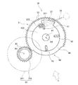
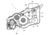
図3は、アジテータギア34、検知ギア35、および移動部材37の、軸方向に見た平面図である。図4は、アジテータギア34、検知ギア35、および移動部材37を、図3中の白抜き矢印Vの方向から見た側面図である。
<3. About agitator gear, detection gear, and moving member>
FIG. 3 is a plan view of the
図2、図3、および図4に示すように、本実施形態の検知ギア35は、円板部40、第1突起41、第2突起42、および第3突起43を有する。なお、図4では、第2突起42および第3突起43の図示が省略されている。円板部40、第1突起41、第2突起42、および第3突起43は、例えば、樹脂により一体に形成される。ただし、検知ギア35は、複数の部材により構成されていてもよい。また、検知ギア35の材料に、樹脂以外の材料が用いられていてもよい。
As shown in FIG. 2, FIG. 3, and FIG. 4, the
円板部40は、第2軸A5に対して垂直に配置された板状の部位である。円板部40は、大径ギア341よりも、ケーシング10の第1外面11に対して近くに位置する。円板部40は、第1端面401と第2端面402とを有する。第1端面401と第2端面402とは、軸方向において、互いに反対側の面である。第1端面401は、ケーシング10の第1外面11と軸方向に向かい合う。第2端面402は、ギアカバー36の内面と軸方向に向かい合う。大径ギア341の一部分は、円板部40とギアカバー36との間に位置する。大径ギア341の一部分と、第2端面402の一部分とは、軸方向に間隔を空けて対向する。
The
円板部40の外周部は、第1領域51と第2領域52とを有する。第1領域51と第2領域52とは、周方向に並ぶ。なお、周方向は、第2軸A5を中心とする円板部40の回転方向である。円板部40は、第1領域51および第2領域52のうち、第1領域51のみに、複数のギア歯53を有する。すなわち、円板部40は、外周部の一部分のみに、複数のギア歯53を有する。複数のギア歯53は、周方向に沿って等間隔に並ぶ。複数のギア歯53は、本発明における第2係合部の一例である。
The outer peripheral portion of the
小径ギア342は、全周に亘って複数のギア歯61を有する。小径ギア342の複数のギア歯61は、本発明における第1係合部の一例である。小径ギア342の複数のギア歯61の一部分は、円板部40の複数のギア歯53の第2軸A5を中心とする外接円の内側に位置する。したがって、小径ギア342の複数のギア歯61と、円板部40の複数のギア歯53とは、互いに係合可能である。新品(未使用)の現像カートリッジ1においては、円板部40の複数のギア歯53の一部分が、小径ギア342の複数のギア歯61の一部分と噛み合っているか、少なくとも接触している。
The
円板部40の第2領域52は、第1領域51よりも第2軸A5側へ凹んでいる。小径ギア342の複数のギア歯61は、第2領域52の回転軌跡の外側に位置する。したがって、小径ギア342の複数のギア歯61と、円板部40の第2領域52とは、互いに係合しない。
The
また、本実施形態の円板部40は、中央に貫通孔44を有する。図2に示すように、ケーシング10の第1外面11には、キャップ部材15が固定される。キャップ部材15は、検知ギア35へ向けて突出する支持軸151を有する。支持軸151は、円板部40の貫通孔44に挿入される。検知ギア35は、支持軸151に支持されながら、第2軸A5を中心として回転する。なお、キャップ部材15の代わりに、第1外面11から支持軸151が延びてもよい。また、キャップ部材15の代わりに、第1外面11に取り付け可能な軸部材が用いられてもよい。この場合、軸部材は、支持軸151を備える。
Moreover, the
第1突起41、第2突起42、および第3突起43は、それぞれ、円板部40の第2端面402からギアカバー36へ向けて、軸方向に突出する。第1突起41、第2突起42、および第3突起43は、検知ギア35の回転方向において、互いに離れている。検知ギア35が回転すると、円板部40と共に、第1突起41、第2突起42、および第3突起43も、第2軸A5を中心として回転する。
The
移動部材37は、本体部371、接触部372、および検知突起373を有する。本体部371、接触部372、および検知突起373は、例えば、樹脂により一体に形成される。本体部371は、スリット状の嵌合溝を有する。嵌合溝は、ギアカバー36の支持孔361の縁に嵌まる。これにより、移動部材37が、ギアカバー36に対して、軸方向と交差する方向に移動可能に支持される。
The moving
接触部372は、本体部371からケーシング10へ向けて、軸方向に延びる。図4に示すように、接触部372は、本体部371と円板部40との間に位置する。接触部372の先端は、大径ギア341よりも、ケーシング10の第1外面11に対して近くに位置する。また、接触部372の先端は、第1突起41、第2突起42、および第3突起43の各々の先端よりも、ケーシング10の第1外面11に対して近くに位置する。また、接触部372は、第1突起41、第2突起42、および第3突起43の、第2軸A5を中心とする外接円の内側に位置する。このため、第2軸A5を中心として検知ギア35が回転すると、第1突起41、第2突起42、および第3突起43は、それぞれ接触部372に接触する。
The
検知突起373は、本体部371からギアカバー36の外部へ向けて、軸方向に延びる。すなわち、接触部372と検知突起373とは、本体部371から互いに軸方向の反対側へ突出する。図4に示すように、本実施形態では、本体部371および検知突起373は、大径ギア341よりも、ケーシング10の第1外面11に対して遠くに位置する。接触部372が軸方向に対して交差する方向に移動すると、接触部372と共に、本体部371および検知突起373も、軸方向に対して交差する方向に移動する。
The
また、ギア部30は、弾性部材であるコイルばね38を有する。コイルばね38の一方の端部は、ケーシング10に接続される。コイルばね38の他方の端部は、移動部材37の本体部371に接続される。コイルばね38は、移動部材37の移動方向に沿って伸縮する。また、コイルばね38は、移動部材37に対して、移動部材37の位置に応じた弾性力を付与する。
Moreover, the
<4.現像カートリッジ装着後の動きについて>
続いて、画像形成装置に新品の現像カートリッジ1が装着された直後の検知ギア35および移動部材37の動きについて、説明する。なお、以下では、検知ギア35の回転開始前の位置を「第1位置」と称し、検知ギア35の回転終了後の位置を「第2位置」と称する。また、移動部材37の初期位置を「第3位置」と称し、移動部材37の移動範囲のうち、「第3位置」とは反対側の端部位置を「第4位置」と称する。
<4. Movement after developing cartridge is installed>
Next, the movement of the
カップリング31に駆動力が供給されると、カップリング31から、アイドルギア33およびアジテータギア34を介して、検知ギア35に動力が伝達される。検知ギア35は、アジテータギア34の小径ギア342と噛み合うことによって、第1位置から第2位置へ向けて、回転を開始する。また、検知ギア35が回転すると、第1突起41、第2突起42、および第3突起43も、第2軸A5を中心として回転する。
When driving force is supplied to the
検知ギア35が第1位置から所定の角度回転すると、まず、第1突起41が、移動部材37の接触部372に接触する。図5および図6は、第1突起41が接触部372に接触した瞬間のギア部30の様子を示した図である。図5は、ギア部30の軸方向に直交する断面を示している。図6は、ギア部30の外観を示している。この時点における移動部材37の位置は、第3位置である。
When the
検知ギア35がさらに回転すると、第1突起41が接触部372を押す。これにより、移動部材37が、第3位置から第4位置へスライド移動する。図7および図8は、移動部材37が第4位置に配置されたときのギア部30の様子を示した図である。図7は、ギア部30の軸方向に直交する断面を示している。図8は、ギア部30外観を示している。移動部材37が第4位置に配置されたときのコイルばね38の長さは、移動部材37が第3位置に配置されたときのコイルばね38の長さよりも長い。
When the
続いて、検知ギア35がさらに回転すると、第1突起41が接触部372から離れる。そうすると、移動部材37は、コイルばね38の弾性力によって、第4位置から第3位置に戻る。
Subsequently, when the
その後、第2突起42が、接触部372に接触し、接触部372を押す。これにより、移動部材37が、第3位置から第4位置へスライド移動する。その後、第2突起42が接触部372から離れる。これにより、移動部材37が、第4位置から第3位置に戻る。また、その後、第3突起43が、接触部372に接触し、接触部372を押す。これにより、移動部材37が、第3位置から第4位置へスライド移動する。その後、第3突起43が接触部372から離れる。これにより、移動部材37が、第4位置から第3位置に戻る。
Thereafter, the
このように、本実施形態では、検知ギア35の回転に伴い、第1突起41、第2突起42、および第3突起43が、順次に接触部372に接触する。これにより、接触部372は、第3位置から第4位置を経て第3位置へ戻る移動を、3回繰り返す。やがて、検知ギア35が第2位置まで回転すると、検知ギア35と小径ギア342との噛み合いが外れる。これにより、アジテータギア34から検知ギア35への動力伝達が途絶える。したがって、検知ギア35は回転を停止する。
As described above, in the present embodiment, the
図6および図8中に二点鎖線で示したように、画像形成装置は、検知レバー92およびセンサ93を有する。検知レバー92は、軸方向に延びる回転軸について回転することが可能である。検知レバー92は、接触面921を有する。接触面921は、移動部材37の検知突起373と接触する。このため、移動部材37が第3位置から第4位置に移動すると、接触面921の位置も変化する。これにより、検知レバー92が、第5位置から第6位置へ回転する。そして、移動部材37が第4位置から第3位置へ戻ると、検知レバー92の位置も、第6位置から第5位置へ戻る。
As shown by a two-dot chain line in FIGS. 6 and 8, the image forming apparatus includes a
センサ93は、検知レバー92の第5位置と第6位置との間の位置の変化を検出する。センサ93には、例えば、光センサ、磁気センサ、または接触式のセンサが用いられる。センサ93は、検知レバー92が第5位置に配置されたときと、検知レバー92が第6位置に配置されたときとで、異なる検出信号を出力する。したがって、センサ93から出力される検出信号は、第3位置から第4位置を経て再び第3位置へ戻る移動部材37の移動を反映したものとなる。画像形成装置は、センサ93からの検出信号に基づいて、現像カートリッジ1に関する情報を取得する。現像カートリッジ1に関する情報には、現像カートリッジ1が新品であることを示す情報や、現像カートリッジ1の仕様(例えば、トナーの量や印刷可能枚数など)が含まれる。
The
このように、本実施形態の現像カートリッジ1では、検知ギア35の第1突起41、第2突起42、および第3突起43の回転によって、検知ギア35とは別の部材である移動部材37が移動する。そして、移動部材37の動きによって、現像カートリッジ1に関する情報が、画像形成装置に伝達される。
Thus, in the developing
第1突起41、第2突起42、第3突起43、および移動部材37は、いずれも、大径ギア341の近傍に位置する。ただし、移動部材37は、大径ギア341の回転軌跡の外側に位置する。このため、移動部材37は、大径ギア341と接触しない。また、検知ギア35が第1位置から第2位置へ回転する間に、第1突起41、第2突起42、および第3突起43の一部と、大径ギア341の一部とは、軸方向に重なる。しかしながら、第1突起41、第2突起42、および第3突起43の各々の先端部と、大径ギア341とは、軸方向において離れている。このため、第1突起41、第2突起42、および第3突起43も、大径ギア341と接触しない。このように、大径ギア341、第1突起41、第2突起42、第3突起43、および移動部材37は、相互の接触を避けつつ、コンパクトに配置される。
The
<5.変形例>
以上、本発明の一実施形態について説明したが、本発明は上記の実施形態に限定されるものではない。
<5. Modification>
Although one embodiment of the present invention has been described above, the present invention is not limited to the above embodiment.
上記の実施形態では、検知ギアは、第1突起、第2突起、および第3突起の3つの突起を有していた。しかしながら、検知ギアが有する突起の数は、1〜2つであってもよく、4つ以上であってもよい。また、各突起の形状は、互いに相違していてもよい。突起の数、各突起の周方向の位置、および各突起の周方向の長さは、現像カートリッジの仕様毎に異なっていてもよい。突起の数、形状、および位置にバリエーションを設けることによって、現像カートリッジの種々の仕様を、画像形成装置に対して示すことができる。 In the above embodiment, the detection gear has three protrusions, the first protrusion, the second protrusion, and the third protrusion. However, the number of protrusions included in the detection gear may be one to two, or four or more. Further, the shape of each protrusion may be different from each other. The number of projections, the circumferential position of each projection, and the circumferential length of each projection may be different for each specification of the developing cartridge. By providing variations in the number, shape, and position of the protrusions, various specifications of the developing cartridge can be shown to the image forming apparatus.
また、上記の実施形態では、第1突起、第2突起、および第3突起が、円板部から軸方向に延びていた。しかしながら、突起の延びる向きは、軸方向以外の向きであってもよい。例えば、検知ギアは、円板部の中央から第2軸に沿って延びる柱状部と、柱状部から径方向外側へ向けて延びる突起とを有していてもよい。また、第1突起、第2突起、および第3突起は、それぞれ別の部品として、円板部に取り付けられてもよい。 In the embodiment described above, the first protrusion, the second protrusion, and the third protrusion extend in the axial direction from the disk portion. However, the direction in which the protrusion extends may be a direction other than the axial direction. For example, the detection gear may include a columnar portion that extends along the second axis from the center of the disc portion, and a protrusion that extends radially outward from the columnar portion. The first protrusion, the second protrusion, and the third protrusion may be attached to the disk portion as separate parts.
また、上記の実施形態では、移動部材は、突起に押されることによって、第3位置から第4位置へ、直線状にスライド移動した。しかしながら、移動部材は、突起に押されることによって、第3位置から第4位置へ、回転移動してもよい。また、上記の実施形態では、移動部材が、突起に押されることによって、軸方向に対して交差する方向に移動した。しかしながら、移動部材は、突起に押されることによって、軸方向に移動してもよい。 In the above embodiment, the moving member is slid linearly from the third position to the fourth position by being pushed by the protrusion. However, the moving member may be rotationally moved from the third position to the fourth position by being pushed by the protrusion. Moreover, in said embodiment, the moving member moved to the direction which cross | intersects with respect to an axial direction by being pushed by protrusion. However, the moving member may move in the axial direction by being pushed by the protrusion.
また、上記の実施形態では、ギア部内の複数のギアが、互いに、ギア歯の噛み合いによって係合していた。しかしながら、ギア部内の複数のギアは、摩擦力により互いに係合していてもよい。例えば、検知ギアの第1領域の外周部に、複数のギア歯の代わりに、摩擦部材(例えばゴム)が設けられてもよい。そして、摩擦部材が、アジテータギアの小径ギアに接触することで、小径ギアと検知ギアとが、互いに係合してもよい。摩擦部材は、第2領域の外周部よりも摩擦係数が高い材料で形成されることが好ましい。また、アジテータギアの外周部に、複数のギア歯の代わりに、摩擦部材が設けられてもよい。 In the above embodiment, the plurality of gears in the gear portion are engaged with each other by meshing of the gear teeth. However, the plurality of gears in the gear portion may be engaged with each other by a frictional force. For example, a friction member (for example, rubber) may be provided on the outer peripheral portion of the first region of the detection gear instead of the plurality of gear teeth. Then, the small diameter gear and the detection gear may be engaged with each other when the friction member contacts the small diameter gear of the agitator gear. The friction member is preferably formed of a material having a higher friction coefficient than the outer peripheral portion of the second region. Further, a friction member may be provided on the outer peripheral portion of the agitator gear instead of the plurality of gear teeth.
また、上記の実施形態では、画像形成装置の検知レバーの位置が、移動部材に押されることによって、変化した。そして、画像形成装置のセンサが、検知レバーの位置の変化を検出した。しかしながら、画像形成装置のセンサは、移動部材自体の位置の変化を検出してもよい。 In the above-described embodiment, the position of the detection lever of the image forming apparatus is changed by being pushed by the moving member. The sensor of the image forming apparatus detects a change in the position of the detection lever. However, the sensor of the image forming apparatus may detect a change in the position of the moving member itself.
また、上記の実施形態では、第2ギアがアジテータギアであった。しかしながら、第2ギアは、アジテータギア以外のギアであってもよい。例えば、第2ギアは、大径ギアと小径ギアとを有し、アジテータとは直接接続されていないアイドルギアであってもよい。 In the above embodiment, the second gear is an agitator gear. However, the second gear may be a gear other than the agitator gear. For example, the second gear may be an idle gear that has a large-diameter gear and a small-diameter gear and is not directly connected to the agitator.
また、上記の実施形態では、弾性部材としてコイルばねを用いていた。しかしながら、コイルばねに代えて、板ばね、トーションばね、弾性を有する樹脂などが、弾性部材として用いられてもよい。 Moreover, in said embodiment, the coil spring was used as an elastic member. However, instead of the coil spring, a plate spring, a torsion spring, an elastic resin, or the like may be used as the elastic member.
また、現像カートリッジの細部の形状については、本願の各図に示された形状と相違していてもよい。また、上記の実施形態や変形例に登場した各要素を、矛盾が生じない範囲で、適宜に組み合わせてもよい。 Further, the detailed shape of the developing cartridge may be different from the shape shown in each drawing of the present application. Moreover, you may combine suitably each element which appeared in said embodiment and modification in the range which does not produce inconsistency.
1 現像カートリッジ
10 ケーシング
11 第1外面
12 トナー室
13 アジテータ
14 開口部
15 キャップ部材
20 現像ローラ
21 ローラ本体
22 ローラシャフト
30 ギア部
31 カップリング
32 現像ギア
33 アイドルギア
34 アジテータギア
35 検知ギア
36 ギアカバー
37 移動部材
38 コイルばね
40 円板部
41 第1突起
42 第2突起
43 第3突起
44 貫通孔
51 第1領域
52 第2領域
53 ギア歯
61 ギア歯
311 カップリング部
312 カップリングギア
313 締結穴
331 入力ギア
332 出力ギア
341 大径ギア
342 小径ギア
361 支持孔
371 本体部
372 接触部
373 検知突起
401 第1端面
402 第2端面
DESCRIPTION OF
Claims (5)
前記筐体の外面に位置し、軸方向に延びる第1軸について回転可能な小径ギアであって、前記小径ギアの周囲の少なくとも一部分に沿って設けられた第1係合部を有する小径ギアと、
前記外面に位置し、前記第1軸について前記小径ギアと共に回転可能な大径ギアであって、前記軸方向において、前記外面から前記小径ギアよりも離れて位置する大径ギアと、
前記外面に位置し、前記第1軸とは異なる第2軸であって前記軸方向に延びる第2軸について、少なくとも第1位置から第2位置へ回転可能な第1ギアであって、
前記第1ギアの周囲の少なくとも一部分に沿って設けられた第2係合部であって前記第1係合部の少なくとも一部と係合する第2係合部と、
前記軸方向において前記外面と向かい合う第1端面と、
前記軸方向において前記第1端面と反対の第2端面であり、前記軸方向において前記大径ギアと間隔を空けて離れ、前記大径ギアよりも前記外面に対して近くに位置する第2端面であって、前記第2端面の一部と、前記大径ギアの一部とが、前記軸方向に向かい合う第2端面と、
前記第2端面に位置する1つ以上の突起であって、前記第1ギアと共に回転し、前記突起の先端部と、前記大径ギアとが前記軸方向において離れ、前記第1ギアが前記第1位置から前記第2位置へ回転する間に、前記突起の回転軌跡の一部と前記大径ギアの一部とが前記軸方向に重なる突起と、
を有する第1ギアと、
前記筐体に対して第3位置と第4位置との間で移動可能な移動部材であって、前記移動部材の少なくとも一部が、前記大径ギアよりも、前記筐体の前記外面に対して遠くに位置する移動部材と、
を備え、
前記移動部材は、
前記大径ギアの回転軌跡の外側に位置し、前記第1ギアが前記第1位置から前記第2位置へ回転するときに、前記突起と接触可能な接触部であって、前記突起と接触することで前記移動部材を前記第3位置から前記第4位置へ移動させる接触部
を有することを特徴とする現像カートリッジ。 A housing capable of containing a developer;
A small-diameter gear that is positioned on the outer surface of the housing and is rotatable about a first shaft extending in the axial direction, and having a first engagement portion provided along at least a part of the periphery of the small-diameter gear; ,
A large-diameter gear positioned on the outer surface and rotatable with the small-diameter gear about the first shaft, the large-diameter gear positioned away from the outer surface from the outer surface in the axial direction;
A second gear located on the outer surface and different from the first axis and extending in the axial direction, the first gear being rotatable at least from the first position to the second position;
A second engagement portion provided along at least a portion of the periphery of the first gear, the second engagement portion engaging with at least a portion of the first engagement portion;
A first end surface facing the outer surface in the axial direction;
A second end surface opposite to the first end surface in the axial direction, spaced apart from the large-diameter gear in the axial direction, and positioned closer to the outer surface than the large-diameter gear A part of the second end surface and a part of the large-diameter gear are opposed to the second end surface in the axial direction;
One or more protrusions located on the second end surface, which rotate together with the first gear, the tip of the protrusion and the large-diameter gear are separated in the axial direction, and the first gear is the first gear A protrusion in which a part of a rotation locus of the protrusion and a part of the large-diameter gear overlap in the axial direction while rotating from one position to the second position;
A first gear having
A moving member that is movable between a third position and a fourth position with respect to the housing, wherein at least a part of the moving member is relative to the outer surface of the housing rather than the large-diameter gear. A moving member located far away,
With
The moving member is
A contact portion that is located outside the rotation locus of the large-diameter gear and that can contact the protrusion when the first gear rotates from the first position to the second position, and is in contact with the protrusion. A developing cartridge having a contact portion for moving the moving member from the third position to the fourth position.
前記第1ギアは、複数の前記突起を有し、
複数の前記突起は、前記第1ギアの回転方向において互いに離れていることを特徴とする現像カートリッジ。 The developing cartridge according to claim 1,
The first gear has a plurality of the protrusions,
The developing cartridge, wherein the plurality of protrusions are separated from each other in the rotation direction of the first gear.
前記第1ギアの少なくとも一部分を覆うギアカバーをさらに有し、
前記ギアカバーが、前記移動部材を移動可能に支持することを特徴とする現像カートリッジ。 The developing cartridge according to claim 1 or 2,
A gear cover covering at least a portion of the first gear;
The developing cartridge, wherein the gear cover movably supports the moving member.
前記移動部材を前記第4位置から前記第3位置に戻すための弾性力を発生させる弾性部材
をさらに備えることを特徴とする現像カートリッジ。 The developing cartridge according to any one of claims 1 to 3,
The developing cartridge further comprising an elastic member for generating an elastic force for returning the moving member from the fourth position to the third position.
前記移動部材は、前記軸方向に対して交差する方向に移動可能であることを特徴とする現像カートリッジ。 The developing cartridge according to any one of claims 1 to 4, wherein
The developing cartridge according to claim 1, wherein the moving member is movable in a direction intersecting the axial direction.
Priority Applications (11)
| Application Number | Priority Date | Filing Date | Title |
|---|---|---|---|
| JP2016062964A JP2017181527A (en) | 2016-03-28 | 2016-03-28 | Developing cartridge |
| PCT/JP2016/087011 WO2017168858A1 (en) | 2016-03-28 | 2016-12-13 | Development cartridge |
| US15/377,314 US9846405B2 (en) | 2016-03-28 | 2016-12-13 | Developing cartridge comprising mechanism for information detection |
| CN201710173065.XA CN107239029B (en) | 2016-03-28 | 2017-03-22 | Developing box |
| CN201720281666.8U CN206671772U (en) | 2016-03-28 | 2017-03-22 | Delevoping cartridge |
| DE102017106462.1A DE102017106462A1 (en) | 2016-03-28 | 2017-03-27 | A development cartridge having an information acquisition mechanism |
| DE202017101744.3U DE202017101744U1 (en) | 2016-03-28 | 2017-03-27 | A development cartridge that captures an information capture mechanism |
| EP17162950.4A EP3226079B1 (en) | 2016-03-28 | 2017-03-27 | Developing cartridge comprising mechanism for information detection |
| US15/845,169 US10073409B2 (en) | 2016-03-28 | 2017-12-18 | Developing cartridge comprising mechanism for information detection |
| US16/122,997 US10303113B2 (en) | 2016-03-28 | 2018-09-06 | Developing cartridge comprising mechanism for information detection |
| US16/407,394 US10649395B2 (en) | 2016-03-28 | 2019-05-09 | Developing cartridge comprising mechanism for information detection |
Applications Claiming Priority (1)
| Application Number | Priority Date | Filing Date | Title |
|---|---|---|---|
| JP2016062964A JP2017181527A (en) | 2016-03-28 | 2016-03-28 | Developing cartridge |
Publications (1)
| Publication Number | Publication Date |
|---|---|
| JP2017181527A true JP2017181527A (en) | 2017-10-05 |
Family
ID=58428148
Family Applications (1)
| Application Number | Title | Priority Date | Filing Date |
|---|---|---|---|
| JP2016062964A Pending JP2017181527A (en) | 2016-03-28 | 2016-03-28 | Developing cartridge |
Country Status (6)
| Country | Link |
|---|---|
| US (4) | US9846405B2 (en) |
| EP (1) | EP3226079B1 (en) |
| JP (1) | JP2017181527A (en) |
| CN (2) | CN107239029B (en) |
| DE (2) | DE202017101744U1 (en) |
| WO (1) | WO2017168858A1 (en) |
Cited By (4)
| Publication number | Priority date | Publication date | Assignee | Title |
|---|---|---|---|---|
| WO2021199425A1 (en) * | 2020-03-31 | 2021-10-07 | ブラザー工業株式会社 | Liquid cartridge |
| WO2021199423A1 (en) * | 2020-03-31 | 2021-10-07 | ブラザー工業株式会社 | Liquid cartridge |
| US11364723B2 (en) | 2020-03-31 | 2022-06-21 | Brother Kogyo Kabushiki Kaisha | Liquid cartridge including circuit board positioned between first protrusion and second protrusion provided on top wall of housing |
| US11453220B2 (en) | 2020-03-31 | 2022-09-27 | Brother Kogyo Kabushiki Kaisha | Liquid cartridge including first and second protrusions on top wall of housing |
Families Citing this family (2)
| Publication number | Priority date | Publication date | Assignee | Title |
|---|---|---|---|---|
| JP2017181527A (en) | 2016-03-28 | 2017-10-05 | ブラザー工業株式会社 | Developing cartridge |
| JP7017091B2 (en) * | 2018-02-22 | 2022-02-08 | ブラザー工業株式会社 | Develop cartridge |
Family Cites Families (17)
| Publication number | Priority date | Publication date | Assignee | Title |
|---|---|---|---|---|
| JP4348632B2 (en) | 2005-02-28 | 2009-10-21 | ブラザー工業株式会社 | Image forming apparatus and developing cartridge |
| JP4857739B2 (en) * | 2005-11-30 | 2012-01-18 | ブラザー工業株式会社 | Image forming apparatus and developing cartridge |
| JP4636037B2 (en) * | 2007-02-28 | 2011-02-23 | ブラザー工業株式会社 | Developer container |
| JP4893369B2 (en) | 2007-02-28 | 2012-03-07 | ブラザー工業株式会社 | Image forming apparatus |
| JP4267052B2 (en) * | 2007-05-15 | 2009-05-27 | キヤノン株式会社 | Color electrophotographic image forming apparatus |
| JP5110963B2 (en) | 2007-05-22 | 2012-12-26 | キヤノン株式会社 | Removable unit individual information reading method and apparatus, and image forming apparatus having the individual information reading apparatus |
| CN201615993U (en) * | 2009-09-11 | 2010-10-27 | 珠海赛纳科技有限公司 | Developing device for an image forming equipment |
| JP5115607B2 (en) * | 2010-08-31 | 2013-01-09 | ブラザー工業株式会社 | Caps and cartridges |
| JP5206776B2 (en) * | 2010-11-30 | 2013-06-12 | ブラザー工業株式会社 | cartridge |
| JP5716498B2 (en) * | 2011-03-31 | 2015-05-13 | ブラザー工業株式会社 | cartridge |
| JP5182402B2 (en) | 2011-08-31 | 2013-04-17 | ブラザー工業株式会社 | cartridge |
| JP2013231831A (en) * | 2012-04-27 | 2013-11-14 | Brother Ind Ltd | Image forming device |
| JP5942735B2 (en) | 2012-09-21 | 2016-06-29 | ブラザー工業株式会社 | cartridge |
| JP6065705B2 (en) | 2013-03-27 | 2017-01-25 | ブラザー工業株式会社 | cartridge |
| JP6064867B2 (en) * | 2013-10-31 | 2017-01-25 | ブラザー工業株式会社 | cartridge |
| JP6079687B2 (en) * | 2014-03-31 | 2017-02-15 | ブラザー工業株式会社 | cartridge |
| JP2017181527A (en) * | 2016-03-28 | 2017-10-05 | ブラザー工業株式会社 | Developing cartridge |
-
2016
- 2016-03-28 JP JP2016062964A patent/JP2017181527A/en active Pending
- 2016-12-13 US US15/377,314 patent/US9846405B2/en active Active
- 2016-12-13 WO PCT/JP2016/087011 patent/WO2017168858A1/en active Application Filing
-
2017
- 2017-03-22 CN CN201710173065.XA patent/CN107239029B/en active Active
- 2017-03-22 CN CN201720281666.8U patent/CN206671772U/en active Active
- 2017-03-27 DE DE202017101744.3U patent/DE202017101744U1/en active Active
- 2017-03-27 DE DE102017106462.1A patent/DE102017106462A1/en not_active Ceased
- 2017-03-27 EP EP17162950.4A patent/EP3226079B1/en active Active
- 2017-12-18 US US15/845,169 patent/US10073409B2/en active Active
-
2018
- 2018-09-06 US US16/122,997 patent/US10303113B2/en active Active
-
2019
- 2019-05-09 US US16/407,394 patent/US10649395B2/en active Active
Cited By (6)
| Publication number | Priority date | Publication date | Assignee | Title |
|---|---|---|---|---|
| WO2021199425A1 (en) * | 2020-03-31 | 2021-10-07 | ブラザー工業株式会社 | Liquid cartridge |
| WO2021199423A1 (en) * | 2020-03-31 | 2021-10-07 | ブラザー工業株式会社 | Liquid cartridge |
| US11364723B2 (en) | 2020-03-31 | 2022-06-21 | Brother Kogyo Kabushiki Kaisha | Liquid cartridge including circuit board positioned between first protrusion and second protrusion provided on top wall of housing |
| US11453220B2 (en) | 2020-03-31 | 2022-09-27 | Brother Kogyo Kabushiki Kaisha | Liquid cartridge including first and second protrusions on top wall of housing |
| US11865844B2 (en) | 2020-03-31 | 2024-01-09 | Brother Kogyo Kabushiki Kaisha | Liquid cartridge including first and second protrusions on top wall of housing |
| US11912038B2 (en) | 2020-03-31 | 2024-02-27 | Brother Kogyo Kabushiki Kaisha | Liquid cartridge including circuit board positioned between first protrusion and second protrusion provided on top wall of housing |
Also Published As
| Publication number | Publication date |
|---|---|
| CN107239029A (en) | 2017-10-10 |
| EP3226079A1 (en) | 2017-10-04 |
| US10649395B2 (en) | 2020-05-12 |
| WO2017168858A1 (en) | 2017-10-05 |
| US9846405B2 (en) | 2017-12-19 |
| US10073409B2 (en) | 2018-09-11 |
| US20190265639A1 (en) | 2019-08-29 |
| CN206671772U (en) | 2017-11-24 |
| DE202017101744U1 (en) | 2017-04-24 |
| EP3226079B1 (en) | 2019-09-18 |
| US20180107150A1 (en) | 2018-04-19 |
| US10303113B2 (en) | 2019-05-28 |
| CN107239029B (en) | 2020-10-27 |
| US20170277117A1 (en) | 2017-09-28 |
| DE102017106462A1 (en) | 2017-09-28 |
| US20190004470A1 (en) | 2019-01-03 |
Similar Documents
| Publication | Publication Date | Title |
|---|---|---|
| WO2017168858A1 (en) | Development cartridge | |
| US11067919B2 (en) | Developing cartridge capable of reducing size of image forming apparatus | |
| US10613471B2 (en) | Developer cartridge provided with gear including protrusion | |
| WO2017154468A1 (en) | Cartridge and imaging device | |
| US9864328B2 (en) | Developer cartridge provided with gear including surface rotatable with gear | |
| JP2017067885A (en) | Developing cartridge | |
| WO2018179487A1 (en) | Development cartridge | |
| JP2017067886A (en) | Developing cartridge | |
| JP2020118988A (en) | Developing cartridge | |
| JP2016224202A (en) | cartridge |