JP2017181228A - Measurement device, measurement method and manufacturing method of article - Google Patents
Measurement device, measurement method and manufacturing method of article Download PDFInfo
- Publication number
- JP2017181228A JP2017181228A JP2016067156A JP2016067156A JP2017181228A JP 2017181228 A JP2017181228 A JP 2017181228A JP 2016067156 A JP2016067156 A JP 2016067156A JP 2016067156 A JP2016067156 A JP 2016067156A JP 2017181228 A JP2017181228 A JP 2017181228A
- Authority
- JP
- Japan
- Prior art keywords
- test object
- image
- measurement
- orientation
- posture
- Prior art date
- Legal status (The legal status is an assumption and is not a legal conclusion. Google has not performed a legal analysis and makes no representation as to the accuracy of the status listed.)
- Withdrawn
Links
Images


Classifications
-
- G—PHYSICS
- G06—COMPUTING; CALCULATING OR COUNTING
- G06T—IMAGE DATA PROCESSING OR GENERATION, IN GENERAL
- G06T7/00—Image analysis
- G06T7/60—Analysis of geometric attributes
-
- G—PHYSICS
- G06—COMPUTING; CALCULATING OR COUNTING
- G06T—IMAGE DATA PROCESSING OR GENERATION, IN GENERAL
- G06T7/00—Image analysis
- G06T7/0002—Inspection of images, e.g. flaw detection
- G06T7/0004—Industrial image inspection
-
- G—PHYSICS
- G06—COMPUTING; CALCULATING OR COUNTING
- G06T—IMAGE DATA PROCESSING OR GENERATION, IN GENERAL
- G06T7/00—Image analysis
- G06T7/70—Determining position or orientation of objects or cameras
- G06T7/73—Determining position or orientation of objects or cameras using feature-based methods
-
- G—PHYSICS
- G06—COMPUTING; CALCULATING OR COUNTING
- G06T—IMAGE DATA PROCESSING OR GENERATION, IN GENERAL
- G06T2207/00—Indexing scheme for image analysis or image enhancement
- G06T2207/30—Subject of image; Context of image processing
- G06T2207/30108—Industrial image inspection
- G06T2207/30164—Workpiece; Machine component
Abstract
Description
本発明は、計測装置、計測方法及び物品の製造方法に関する。 The present invention relates to a measuring device, a measuring method, and an article manufacturing method.
近年、ロボットが工業製品の組立などの複雑なタスクを行うようになりつつあり、ロボットが当該タスクを行うには操作対象物の位置姿勢の計測(認識)が必要となる。対象物の位置姿勢を計測する技術として、カメラでの撮像により得られた濃淡画像と距離画像との両方を利用する方法がある。距離画像を取得するためには、例えばパターンを投影する手段が必要となる為、装置のコストが上昇してしまう。安価な装置構成で位置姿勢を認識したい場合、濃淡画像のみを利用する方法が望ましいが、距離画像を用いない為、誤計測が生じやすい。誤計測を低減する為、特許文献1は、平面上での対象物の安定姿勢を予め登録しておき、登録した安定姿勢のうち濃淡画像データに最も合致(整合)する安定姿勢を選択し、当該安定姿勢を初期姿勢としてより正確な位置姿勢を得る方法を開示している。 In recent years, robots are performing complex tasks such as assembly of industrial products, and in order for robots to perform such tasks, it is necessary to measure (recognize) the position and orientation of an operation target. As a technique for measuring the position and orientation of an object, there is a method of using both a grayscale image and a distance image obtained by imaging with a camera. In order to acquire a distance image, for example, a means for projecting a pattern is required, which increases the cost of the apparatus. When it is desired to recognize the position and orientation with an inexpensive apparatus configuration, a method using only a grayscale image is desirable, but since a distance image is not used, erroneous measurement is likely to occur. In order to reduce erroneous measurement, Patent Document 1 previously registers a stable posture of an object on a plane, selects a stable posture that most closely matches (matches) grayscale image data among the registered stable postures, A method for obtaining a more accurate position and orientation using the stable posture as an initial posture is disclosed.
しかしながら、特許文献1の方法は、対象物同士の重なりがない状態で対象物が平面上に載置されていることを前提とし、対象物同士の重なりを想定していない。 However, the method of Patent Literature 1 is based on the premise that the objects are placed on a plane in a state where the objects do not overlap with each other, and does not assume the overlap between the objects.
本発明は、例えば、重なり合った対象物の計測に有利な計測装置を提供することを目的とする。 An object of the present invention is, for example, to provide a measuring device that is advantageous for measuring overlapping objects.
上記課題を解決するために、本発明の一側面である計測装置は、撮像により得られた画像に基づいて物体の位置および姿勢の計測を行う処理部を有する計測装置であって、前記処理部は、前記画像に基づいて前記物体が置かれている面の特定を行い、該特定に基づいて前記計測を行う。 In order to solve the above-described problem, a measurement apparatus according to one aspect of the present invention is a measurement apparatus having a processing unit that measures the position and orientation of an object based on an image obtained by imaging, the processing unit Performs identification of the surface on which the object is placed based on the image, and performs the measurement based on the identification.
本発明によれば、例えば、重なり合った対象物の計測に有利な計測装置を提供することができる。 According to the present invention, for example, it is possible to provide a measuring device that is advantageous for measuring overlapping objects.
(第1実施形態)
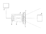
図1は、本発明の第1実施形態における位置姿勢計測装置の全体図である。本実施形態における位置姿勢計測装置は、濃淡画像を利用して被検物(被計測物)の位置および姿勢を計測する装置である。位置姿勢計測装置は、照明部1、撮像部2及び演算処理部3を有する。照明部1は、被検物4を均一に照明するための照明部であり、例えば、多数のLED光源7を撮像部2の光軸中心にリング状に配置したリング照明が用いられる。なお、照明部1はリング照明に限定されるものではなく、バー照明や同軸落斜照明など被検物4を略均一に照明できるものであれば構わない。
(First embodiment)
FIG. 1 is an overall view of a position / orientation measurement apparatus according to a first embodiment of the present invention. The position / orientation measurement apparatus according to the present embodiment is an apparatus that measures the position and orientation of a test object (measurement object) using a grayscale image. The position / orientation measurement apparatus includes an illumination unit 1, an imaging unit 2, and an arithmetic processing unit 3. The illumination unit 1 is an illumination unit for uniformly illuminating the
撮像部2は、撮像光学系5とイメージセンサー6を含む。撮像光学系5は、照明部1により均一照明された被検物4をイメージセンサー6に結像するための光学系である。また、イメージセンサー6は、被検物4を撮像するための素子であり、例えば、CMOSセンサ、CCDセンサなどを用いることができる。演算処理部3(処理部)は、被検物4の位置姿勢を算出するものである。まず、撮像部2によって取得された濃淡画像に対して、Canny法などのエッジ検出アルゴリズムを用いて、被検物4の稜線および輪郭に相当するエッジ情報を抽出し、エッジ検出画像を算出する。続いて、上記のエッジ検出画像を入力画像として、各被検物の位置姿勢をそれぞれ算出する。
The imaging unit 2 includes an imaging
図2は、計測対象である被検物4(被計測物)の配置状態の一例を示した図である。本実施形態では、複数の被検物4が載置面20に載置されている。被検物4は、孤立状態の被検物と、被検物同士が重なった重なり状態の被検物が混在した状態で載置面20の上に載置されている。載置面20の形状は、平面に限定されるものではなく、例えば、曲面形状や段差形状など任意の形状であっても構わない。
FIG. 2 is a diagram illustrating an example of an arrangement state of the test object 4 (measurement object) that is a measurement target. In the present embodiment, a plurality of
本実施形態では、被検物の載置面の三次元座標が既知の場合と未知の場合(載置面を特定できる場合とできない場合)の両方が混在する状況下で、位置姿勢の誤検出の発生を最大限抑制する。そのため、通常の位置姿勢推定では、被検物毎にモデルフィッティング時の推定姿勢候補の変更を行わないのに対して、本実施形態では、載置面の三次元座標が既知か否かに応じて被検物ごとに推定姿勢候補を切り替える。載置面の三次元座標が既知の場合には、既知の載置面20に対して被検物4が安定してとり得る姿勢が重力により限定されるので、部品の形状と載置面の形状情報に基づき、推定姿勢候補の自由度を限定することで推定精度を高めることができる。載置面の三次元座標が未知の場合には、任意の姿勢を推定候補としたモデルフィッティングを行うことで姿勢限定条件に含まれない姿勢も正しく認識することができる。このように被検物の載置面の三次元形状が既知であるか否かに応じて、最適なモデルフィッティング方法を選択する事で、誤検出の発生を抑制することが可能となる。
In this embodiment, the position / orientation is erroneously detected in a situation where both the case where the three-dimensional coordinates of the placement surface of the test object are known and the case where the 3D coordinates are unknown (when the placement surface can be specified or not) are mixed. To minimize the occurrence of Therefore, in the normal position and orientation estimation, the estimated orientation candidates at the time of model fitting are not changed for each test object, whereas in this embodiment, depending on whether or not the three-dimensional coordinates of the placement surface are known To switch the estimated posture candidates for each test object. When the three-dimensional coordinates of the mounting surface are known, the posture that the
次に、図3を用いて姿勢候補の設定を事前に行う場合の計測フローを説明する。図3は、被検物4の位置姿勢を計測する処理のフローを示す図である。本実施形態では、予め画像領域毎の安定姿勢を領域分割により設定しておく事でランタイムの部品位置姿勢推定を効率よく行う事ができる。図3において、ステップS1〜ステップS3は計測前に事前に行っておく工程であり、ステップS4〜ステップS9のステップは計測時に行うランタイムの処理である。
Next, a measurement flow when setting posture candidates in advance will be described with reference to FIG. FIG. 3 is a diagram illustrating a process flow for measuring the position and orientation of the
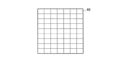
ステップS1は、撮像画像の領域分割を行う工程である。載置面が平面である場合には、撮像画像内のどの領域でも載置面に対してとり得る姿勢候補は変わらないが、載置面が曲面や段差形状の場合には、載置面内で領域毎にとり得る姿勢候補は異なる。載置面内で分割領域毎にとり得る姿勢候補が異なる場合、分割領域毎に被検物がとり得る姿勢候補を予め登録しておく事で計算を効率的に行う事ができる。本工程では、図4で示されるようにイメージセンサー6で撮像される撮像画像の領域分割を行う。図4は、撮像画像の分割領域を示した図である。分割領域40の大きさは安定姿勢が同一と見なせる載置面領域の大きさで決定されるが、載置面が被検物の供給領域であることを考えると被検物サイズ以下の範囲で安定姿勢が変化するとは考えられない。従って本実施形態では、被検物4のサイズに応じて分割領域40の大きさを決定し、例えば、イメージセンサー6上で被検物4が10×10画素のサイズで撮像される場合には、分割領域40の大きさは10×10画素に設定する。なお、分割領域40の大きさは、被検物のサイズに合わせることに限定されるものではなく、分割領域は任意のサイズであって構わない。
Step S <b> 1 is a step of dividing the captured image into regions. If the placement surface is a flat surface, the possible postures for the placement surface are not changed in any region in the captured image, but if the placement surface is a curved surface or a stepped shape, The possible posture candidates for each region are different. In the case where the posture candidates that can be taken for each divided region in the placement surface are different, calculation can be efficiently performed by registering in advance the posture candidates that can be taken by the test object for each divided region. In this step, as shown in FIG. 4, the region of the captured image captured by the
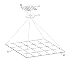
ステップS2は、ステップS1で算出した各分割領域に対して載置面の三次元モデルを対応づける工程である。本工程では、まず、既知である載置面の三次元形状モデルとカメラ座標空間上の載置面の位置姿勢情報に基づいて、カメラ座標空間上に配置された載置面の三次元形状モデルをイメージセンサー6の画像平面に射影する。画像平面への射影方法の一例は、ピンホールカメラモデルに基づいた射影である。事前に実施されたキャリブレーションにより得られているカメラの内部パラメータ(焦点距離、主点)と外部パラメータ(位置、姿勢)を用いて載置面の三次元モデルを画像平面に射影する。続いて、図5に示されるように、イメージセンサー6の各画素と上記で画像平面に射影された載置面の三次元モデル52の対応関係を決定する。イメージセンサー6上の画素番地50に対応する載置面の領域が、対応領域51である。そして、上記対応関係に基づいて、ステップS1で決定されたイメージセンサー6の各分割領域に対して、カメラ座標空間上の載置面の三次元モデル上の対応領域をそれぞれ決定する。
Step S2 is a step of associating a three-dimensional model of the placement surface with each divided region calculated in step S1. In this process, first, based on the known three-dimensional model of the placement surface and the position and orientation information of the placement surface in the camera coordinate space, the three-dimensional shape model of the placement surface arranged in the camera coordinate space Is projected onto the image plane of the
ステップS3は、分割領域毎に載置面に対して被検物がとり得る姿勢を予め登録する工程である。本工程では、前述のステップで載置面の三次元モデルに対応づけられた撮像画像の分割領域ごとに、被検物4の三次元モデルが載置面の三次元モデルに対してとり得る姿勢を登録する。例えば、被検物4の三次元モデルが図6(A)に示される形状の場合には、載置面の三次元モデルに対してとり得る姿勢は図6(B)に示される計4姿勢となる。ステップS4は、被検物4の画像を撮像する工程である。撮像画像は、照明部1により均一照明された被検物4を撮像部2で撮像することにより得られる。
Step S3 is a step of previously registering postures that the test object can take with respect to the placement surface for each divided region. In this step, the posture that the 3D model of the
ステップS5は、被検物の載置領域を検出する工程である。本工程では、ステップS4で取得された撮像画像に基づいて、被検物4が存在する領域を抽出し、載置領域を設定する工程である。被検物が存在しているか否かの判断は、例えば、撮像画像を二値化した二値画像により行われ、被検物のサイズに相当する面積以上の連結領域がある場合には被検物が存在する領域として判断する。そして、連結領域を囲むように載置領域を設定する。図7は、載置領域を示した図である。図7においては、被検物4の反射率が載置面20に対して高い場合を想定しており、二値化画像において白で表示される被検物4を白、黒で表示される載置面20をドットで表している。白色のシルエットで表示される被検物4の連結領域を囲むように載置領域80〜84が設定されている。
Step S5 is a step of detecting the placement area of the test object. In this process, based on the captured image acquired in step S4, an area where the
ステップS6は、被検物の載置面の三次元座標が既知であるか否か、すなわち、載置面を特定できるか否かの判定を行う工程である。本工程の被検物の載置面の三次元座標が既知であるか否かの判定は、被検物が孤立状態か重なり状態にあるかを判定することにより行われる。被検物が他の被検物に重なっておらず孤立状態にある場合には、被検物は載置面のみに接地されるため、被検物の載置面の三次元座標は既知となる(載置面を特定できる)。一方、被検物同士が重なり状態にある場合には被検物は他の被検物の上に載置されるため、被検物の載置面の三次元座標は未知となる(載置面を特定できない)。 Step S6 is a step of determining whether or not the three-dimensional coordinates of the mounting surface of the test object are known, that is, whether or not the mounting surface can be specified. The determination as to whether or not the three-dimensional coordinates of the mounting surface of the test object in this step are known is performed by determining whether the test object is in an isolated state or an overlapping state. When the test object is not overlapped with another test object and is in an isolated state, the test object is grounded only on the mounting surface, so that the three-dimensional coordinates of the mounting surface of the test object are known. (The mounting surface can be specified). On the other hand, when the specimens are in an overlapping state, the specimen is placed on another specimen, so that the three-dimensional coordinates of the placement surface of the specimen are unknown (placement). Face cannot be identified).
本工程では、被検物が孤立状態か重なり状態にあるかを判定する為に、例えば、ステップS5で算出された二値画像のシルエットの面積を算出する。そして、算出されたシルエットの面積が、閾値より大きいか否かを判断する。算出されたシルエットの面積が、閾値より大きい場合には複数の被検物が重なり合った状態にあると判定され、閾値以下である場合には、被検物が孤立状態の単一部品であると判定される。閾値は、例えば、予め設定された被検物4の三次元モデルから想定される被検物4の最大面積であってもよいし、任意に設定された値であってもよい。例えば、図7において、撮像画像から算出された白色のシルエットの面積が想定最大面積に対して大きい場合には、複数の被検物が重なり合った状態にあると判定され、小さい場合には孤立状態の単一部品であると判定される。上記の重なり有無の判定は、ステップS5で決定された全ての載置領域に対して行われる。
In this step, in order to determine whether the test object is in an isolated state or an overlapping state, for example, the area of the silhouette of the binary image calculated in step S5 is calculated. Then, it is determined whether or not the calculated silhouette area is larger than a threshold value. When the calculated silhouette area is larger than the threshold value, it is determined that a plurality of test objects are in an overlapping state. When the calculated silhouette area is equal to or lower than the threshold value, the test object is an isolated single part. Determined. The threshold value may be, for example, the maximum area of the
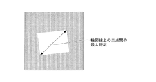
なお、本実施形態における重なりの有無の判定基準はシルエットの面積に限定されるものではなく、例えば、輪郭上の二点の最大距離(距離の最大値)など、重なりの有無の判定が出来るものであればよい。輪郭上の二点の最大距離(距離の最大値)とは、図8に示されるように、シルエットの輪郭を抽出し、抽出した輪郭上の二点間の距離を算出し、その中での距離が最大となる二点の距離である。算出した輪郭線上の二点間の最大距離が、閾値より長い場合には、複数の被検物が重なり合った状態にあると判定され、閾値以下である場合は、被検物が孤立状態の単一部品であると判定される。この閾値は、例えば、予め設定された被検物4の三次元モデルから想定される被検物4の輪郭上の二点間の最大距離でもよいし、予め設定された任意の長さであっても良い。
Note that the criterion for determining whether or not there is an overlap in the present embodiment is not limited to the area of the silhouette. For example, it is possible to determine whether or not there is an overlap, such as the maximum distance between two points on the contour (maximum distance). If it is. As shown in FIG. 8, the maximum distance between two points on the contour (maximum distance) is to extract the contour of the silhouette and calculate the distance between the two points on the extracted contour. The distance between the two points where the distance is the maximum. When the calculated maximum distance between two points on the contour line is longer than the threshold value, it is determined that a plurality of test objects are in an overlapping state, and when the maximum distance is equal to or less than the threshold value, the test object is simply in an isolated state. It is determined that it is a single part. This threshold value may be, for example, the maximum distance between two points on the contour of the
ステップS6で被検物の載置面の三次元座標が既知と判定された場合はステップS7−1に進み、被検物の載置面の三次元座標が未知と判定された場合はステップS7−2に進む。
ステップS7−1は、載置面に対して被検物がとり得る姿勢を姿勢推定候補に設定する工程である。被検物4が被検物の載置面の三次元座標が既知であると判定された場合には、被検物4は載置面のみに接していることが確定している為、被検物4のとり得る姿勢はステップS3で登録した姿勢のいずれかである。そのため、ステップS3で登録した載置面に対して被検物がとり得る姿勢を推定姿勢候補として設定する。そして、ステップS1で設定された分割領域と被検物の載置領域の対応関係に基づいて、被検物毎に推定姿勢候補を設定する。被検物の載置領域がステップS1で設定された複数の分割領域をまたぐ場合には、例えば、複数の分割領域で、登録された全ての姿勢を推定姿勢候補とすればよい。なお、本実施形態において、被検物の載置領域が複数の分割領域をまたぐ場合の推定姿勢候補の設定は上記に限定されるものではなく、例えば、複数の分割領域のうち、一部の分割領域に登録された姿勢を推定姿勢候補としても構わない。
If it is determined in step S6 that the three-dimensional coordinates of the mounting surface of the test object are known, the process proceeds to step S7-1. If the three-dimensional coordinates of the mounting surface of the test object is determined to be unknown, step S7 is performed. Proceed to -2.
Step S7-1 is a step of setting the posture that the test object can take with respect to the placement surface as a posture estimation candidate. If the
また、本実施形態では、領域毎に予め推定姿勢候補を設定したが、予め設定していない場合には本工程において載置面の三次元座標と被検物形状に基づき推定姿勢候補となる安定姿勢を計算すればよい。事前に姿勢候補が設定できないケースとしては、例えば、被検物同士が重なりあっているが、図9のように下に載置された被検物4Aの位置姿勢が計測時に特定でき、計測時に被検物4Bの載置面の三次元座標が既知となった場合等が想定される。また、被検物がベルトコンベア上に載置され載置面の三次元座標が動的に変化する場合なども想定される。
Further, in this embodiment, the estimated posture candidates are set in advance for each region. However, in the case where the estimated posture candidates are not set in advance, in this step, the estimated posture candidates are stable based on the three-dimensional coordinates of the placement surface and the shape of the test object. The posture should be calculated. As a case where posture candidates cannot be set in advance, for example, specimens overlap each other, but the position and orientation of the
ステップS7−2は、任意の姿勢を姿勢推定候補に設定する工程である。被検物の載置面の三次元座標が未知であると判定された場合には、被検物は他の被検物の上に重なって載置されている為、ステップS3で登録した姿勢とは異なる姿勢にあり、被検物の載置領域における載置面の三次元座標を予測する事ができない。そのため、被検物の載置面の三次元座標が未知であると判定された場合には、任意の姿勢を推定姿勢候補として設定する。なお、姿勢の設定分解能は、目標とする姿勢精度に応じて設定される。 Step S7-2 is a step of setting an arbitrary posture as a posture estimation candidate. If it is determined that the three-dimensional coordinates of the mounting surface of the test object are unknown, the test object is placed on top of another test object, so the posture registered in step S3 The three-dimensional coordinates of the placement surface in the placement area of the test object cannot be predicted. Therefore, when it is determined that the three-dimensional coordinates of the mounting surface of the test object are unknown, an arbitrary posture is set as the estimated posture candidate. Note that the posture setting resolution is set according to the target posture accuracy.
最後に、ステップS8とステップS9により、被検物4の位置姿勢を算出する。位置姿勢の算出は、例えば、概略の位置姿勢を推定する工程と、その概略位置姿勢を初期値としてより高精度に位置算出を推定する工程の二つに分けて行われる。ステップS8は、被検物の概略位置姿勢を検出する工程である。本工程では、例えば、アンサンブル分類木のアルゴリズムを用いた手法で被検物の概略位置姿勢を検出する。アンサンブル分類木のアルゴリズムを用いた手法では、まず、事前にいろいろな方向から撮像された被検物の画像を用いて多量の学習パターンを生成し、その学習パターンからアンサンブル分類木を生成する。そして、そのアンサンブル分類木を用いて、多数の姿勢投票面に投票を行い、投票スコアに基づいて各被検物の概略位置姿勢を特定する。なお、被検物の概略位置姿勢を検出する方法は、アンサンブル分類木のアルゴリズムを用いた手法に限られるものではない。また、ステップS8は三次元座標が基地であるか否かの判定の前に行ってもよく、ステップS4とステップS9の間で行えばよい。
Finally, the position and orientation of the
ステップS9は、被検物の位置姿勢を検出する工程である。本工程では、算出された被検物の概略位置姿勢を初期値として、既知の被検物の三次元モデルを撮像結果にモデルフィッティングすることで高精度に位置算出を推定する。具体的には、ステップS8で算出した概略位置姿勢を初期値として、ステップS7−1およびステップS7−2で設定された姿勢候補のいずれかを推定姿勢候補としてモデルフィッティングを行う。モデルフィッティングは、例えば、被検物の三次元モデルに対して設定された輪郭や稜線に対応する幾何特徴(エッジ)と撮像画像から抽出された幾何特徴(エッジ)の差を用いて、その差が最小となるよう被検物の位置姿勢を推定することで行われる。なお、上述のモデルフィッティングは、ステップS5で設定された載置領域ごとに推定姿勢候補を切り替えて行う。 Step S9 is a step of detecting the position and orientation of the test object. In this step, the calculated approximate position and orientation of the test object are used as initial values, and the position calculation is estimated with high accuracy by model fitting a known three-dimensional model of the test object to the imaging result. Specifically, model fitting is performed using the approximate position and orientation calculated in step S8 as initial values and any of the orientation candidates set in steps S7-1 and S7-2 as estimated posture candidates. Model fitting is performed by using, for example, a difference between a geometric feature (edge) corresponding to a contour or a ridge line set for a three-dimensional model of a test object and a geometric feature (edge) extracted from a captured image. This is performed by estimating the position and orientation of the test object so that is minimized. The model fitting described above is performed by switching the estimated posture candidates for each placement area set in step S5.
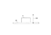
なお、被検物の載置面の三次元座標が既知である場合には、前述の姿勢制約に加えて、図10に示されるような、重力方向の高さ100の制限も加えた位置姿勢推定を行うことが可能である。被検物4が孤立状態である場合には、重力により被検物4は載置面に接地しているはずであるので、例えば、高さ100を被検物4の最大高さに制限する。本実施形態におけるモデルフィッティングは、被検物の姿勢制約のみに限定したものではなく、姿勢制約に加え上記の高さの制約も加えるものであっても構わない。
In addition, when the three-dimensional coordinates of the mounting surface of the test object are known, in addition to the above-described posture constraint, the position and posture including the limitation of the
また、載置面が球面であるなど、載置面の位置ごとに被検物のとり得る姿勢が変わる場合は、載置面が平面であることを前提としている位置姿勢の計測方法では、被検物同士の重なりがなくても、被検物の位置姿勢を誤計測してしまう恐れがある。これに対し、ステップS1からステップS5、ステップS7−1、ステップS8、ステップS9を行うことで、画像上の領域と載置面の三次元座標を対応付け、分割領域ごとに被検物の姿勢推定候補を限定することで、誤計測を抑制できる。この場合には、ステップS6の判定は行われない。 In addition, when the posture that the test object can take varies depending on the position of the mounting surface, such as a spherical surface, the position and orientation measurement method that assumes that the mounting surface is a flat surface Even if there is no overlap between the specimens, the position and orientation of the specimen may be erroneously measured. On the other hand, by performing step S1 to step S5, step S7-1, step S8, and step S9, the region on the image and the three-dimensional coordinates of the placement surface are associated with each other, and the posture of the test object for each divided region. By limiting the estimation candidates, erroneous measurement can be suppressed. In this case, the determination in step S6 is not performed.
以上のように、本実施形態によれば、位置姿勢の計測に濃淡画像のみを利用した場合に被検物同士が重なりあった状態であっても、被検物の位置姿勢の誤計測を抑制する計測装置を提供することができる。なお、本実施形態は濃淡画像を利用した位置姿勢計測装置に対して特に有効な技術であるが、これに限定されるものではなく、距離画像を利用した位置姿勢計測装置や濃淡画像と距離画像の両方を利用した位置姿勢計測装置に適用しても構わない。 As described above, according to the present embodiment, when only grayscale images are used for position and orientation measurement, erroneous measurement of the position and orientation of the test object is suppressed even when the test objects overlap each other. A measuring device can be provided. This embodiment is a technique that is particularly effective for a position / orientation measurement apparatus that uses a grayscale image. However, the present invention is not limited to this, and a position / orientation measurement apparatus that uses a distance image, a grayscale image, and a distance image. You may apply to the position and orientation measurement apparatus using both.
(物品の製造方法に係る実施形態)
以上に説明した実施形態に係る計測装置は、物品製造方法に使用しうる。当該物品製造方法は、当該計測装置を用いて物体の計測を行う工程と、当該工程で計測を行われた物体または当該工程で計測を行われるべき物体の処理を行う工程と、を含みうる。当該処理は、例えば、加工、切断、搬送、組立(組付)、検査、および選別のうちの少なくともいずれか一つを含みうる。本実施形態の物品製造方法は、従来の方法に比べて、物品の性能・品質・生産性・生産コストのうちの少なくとも1つにおいて有利である。
(Embodiment related to article manufacturing method)
The measuring device according to the embodiment described above can be used in an article manufacturing method. The article manufacturing method may include a step of measuring an object using the measuring device, and a step of processing an object measured in the step or an object to be measured in the step. The process can include, for example, at least one of processing, cutting, conveyance, assembly (assembly), inspection, and selection. The article manufacturing method of the present embodiment is advantageous in at least one of the performance, quality, productivity, and production cost of the article as compared with the conventional method.
以上、本発明の好ましい実施形態について説明したが、本発明は、これらの実施形態に限定されず、その要旨の範囲内で種々の変形および変更が可能である。 As mentioned above, although preferable embodiment of this invention was described, this invention is not limited to these embodiment, A various deformation | transformation and change are possible within the range of the summary.
1 演算処理部
4 被検物
20 載置面
DESCRIPTION OF SYMBOLS 1
Claims (11)
前記処理部は、前記画像に基づいて前記物体が置かれている面の特定を行い、該特定に基づいて前記計測を行うことを特徴とする計測装置。 A measurement device having a processing unit that measures the position and orientation of an object based on an image obtained by imaging,
The processing unit specifies a surface on which the object is placed based on the image, and performs the measurement based on the specification.
前記画像に基づいて前記物体が置かれている面の特定を行い、
前記特定に基づいて前記計測を行う、
ことを特徴とする計測方法。 A measurement method for measuring the position and orientation of an object based on an image obtained by imaging,
Identify the surface on which the object is placed based on the image,
Performing the measurement based on the identification;
A measuring method characterized by this.
前記工程で前記計測が行われた前記物体を処理する工程と、を含む
ことを特徴とする物品の製造方法。
A step of measuring the position and orientation of an object using the measuring device according to any one of claims 1 to 9,
And a step of processing the object for which the measurement has been performed in the step.
Priority Applications (2)
| Application Number | Priority Date | Filing Date | Title |
|---|---|---|---|
| JP2016067156A JP2017181228A (en) | 2016-03-30 | 2016-03-30 | Measurement device, measurement method and manufacturing method of article |
| US15/469,938 US20170287156A1 (en) | 2016-03-30 | 2017-03-27 | Measurement apparatus, measurement method, and article manufacturing method |
Applications Claiming Priority (1)
| Application Number | Priority Date | Filing Date | Title |
|---|---|---|---|
| JP2016067156A JP2017181228A (en) | 2016-03-30 | 2016-03-30 | Measurement device, measurement method and manufacturing method of article |
Publications (1)
| Publication Number | Publication Date |
|---|---|
| JP2017181228A true JP2017181228A (en) | 2017-10-05 |
Family
ID=59959539
Family Applications (1)
| Application Number | Title | Priority Date | Filing Date |
|---|---|---|---|
| JP2016067156A Withdrawn JP2017181228A (en) | 2016-03-30 | 2016-03-30 | Measurement device, measurement method and manufacturing method of article |
Country Status (2)
| Country | Link |
|---|---|
| US (1) | US20170287156A1 (en) |
| JP (1) | JP2017181228A (en) |
Families Citing this family (2)
| Publication number | Priority date | Publication date | Assignee | Title |
|---|---|---|---|---|
| CN114683269B (en) * | 2020-12-31 | 2024-02-27 | 北京极智嘉科技股份有限公司 | Robot and positioning method thereof |
| CN112758641A (en) * | 2020-12-31 | 2021-05-07 | 国网山东省电力公司营销服务中心(计量中心) | Material posture recognition and correction system and method on production line |
Family Cites Families (9)
| Publication number | Priority date | Publication date | Assignee | Title |
|---|---|---|---|---|
| JPS4940715B2 (en) * | 1972-03-06 | 1974-11-05 | ||
| JP2919284B2 (en) * | 1994-02-23 | 1999-07-12 | 松下電工株式会社 | Object recognition method |
| CN1162681C (en) * | 1999-03-19 | 2004-08-18 | 松下电工株式会社 | Three-D object recognition method and pin picking system using the method |
| JP4940715B2 (en) * | 2006-03-15 | 2012-05-30 | 日産自動車株式会社 | Picking system |
| US7313464B1 (en) * | 2006-09-05 | 2007-12-25 | Adept Technology Inc. | Bin-picking system for randomly positioned objects |
| JP5533727B2 (en) * | 2011-02-18 | 2014-06-25 | 株式会社安川電機 | Work picking system |
| JP5447483B2 (en) * | 2011-10-04 | 2014-03-19 | 株式会社安川電機 | Robot system and method of manufacturing workpiece |
| JP5897532B2 (en) * | 2013-11-05 | 2016-03-30 | ファナック株式会社 | Apparatus and method for picking up articles placed in three-dimensional space by robot |
| JP5897624B2 (en) * | 2014-03-12 | 2016-03-30 | ファナック株式会社 | Robot simulation device for simulating workpiece removal process |
-
2016
- 2016-03-30 JP JP2016067156A patent/JP2017181228A/en not_active Withdrawn
-
2017
- 2017-03-27 US US15/469,938 patent/US20170287156A1/en not_active Abandoned
Also Published As
| Publication number | Publication date |
|---|---|
| US20170287156A1 (en) | 2017-10-05 |
Similar Documents
| Publication | Publication Date | Title |
|---|---|---|
| US9529945B2 (en) | Robot simulation system which simulates takeout process of workpieces | |
| JP6465682B2 (en) | Information processing apparatus, information processing method, and program | |
| JP5671281B2 (en) | Position / orientation measuring apparatus, control method and program for position / orientation measuring apparatus | |
| JP6736257B2 (en) | Information processing device, information processing method, and program | |
| JP2017096750A (en) | Positioning method, positioning apparatus, program and computer readable recording medium | |
| JP6566768B2 (en) | Information processing apparatus, information processing method, and program | |
| TWI532116B (en) | Method and system for wafer registration | |
| JP2021170404A (en) | Image processing method and imaging device | |
| US20180247150A1 (en) | Information processing device, information processing method, and article manufacturing method | |
| JP2015056057A (en) | Method of estimating posture and robot | |
| JP2019192248A (en) | System and method for stitching sequential images of object | |
| JP5342413B2 (en) | Image processing method | |
| CN112334761B (en) | Defect discriminating method, defect discriminating apparatus, and recording medium | |
| KR20210091189A (en) | Optimization of setup steps in automated visual inspection processes | |
| CN109308714A (en) | Camera and laser radar information method for registering based on classification punishment | |
| US10228239B2 (en) | Measuring apparatus, measuring method, and article manufacturing method | |
| JP2017181228A (en) | Measurement device, measurement method and manufacturing method of article | |
| JP2016161351A (en) | Measurement apparatus | |
| JP2017198470A (en) | Measurement device, measurement method, system, and goods manufacturing method | |
| JP5976089B2 (en) | Position / orientation measuring apparatus, position / orientation measuring method, and program | |
| JP2007114168A (en) | Image processing method, device, and program | |
| TWI427263B (en) | Method and apparatus of measuring height of projections, and program therefor | |
| US20180130230A1 (en) | Recognition apparatus, determination method, and article manufacturing method | |
| JP5342977B2 (en) | Image processing method | |
| CN114264243A (en) | Method for detecting crimping welding spots and measuring line arc height between crimping welding spots |
Legal Events
| Date | Code | Title | Description |
|---|---|---|---|
| A621 | Written request for application examination |
Free format text: JAPANESE INTERMEDIATE CODE: A621 Effective date: 20190227 |
|
| A761 | Written withdrawal of application |
Free format text: JAPANESE INTERMEDIATE CODE: A761 Effective date: 20190920 |