以下に添付図面を参照しながら、本開示の好適な実施の形態について詳細に説明する。なお、本明細書及び図面において、実質的に同一の機能構成を有する構成要素については、同一の符号を付することにより重複説明を省略する。
Hereinafter, preferred embodiments of the present disclosure will be described in detail with reference to the accompanying drawings. In addition, in this specification and drawing, about the component which has the substantially same function structure, duplication description is abbreviate | omitted by attaching | subjecting the same code | symbol.
なお、説明は以下の順序で行うものとする。
1.第1の実施の形態
1−1.圧排装置の全体構成
1−2.圧排子の構成
1−3.圧力センサの詳細構成
1−4.圧力センサの他の例
1−5.圧力センサ以外のセンサの例
1−6.解析装置の構成
1−7.使用例
2.第2の実施形態
2−1.圧排装置の全体構成
2−2.解析装置の構成
2−3.アーム装置の構成
2−4.使用例
3.第3の実施形態
3−1.圧排装置の全体構成
3−2.解析装置の構成
3−3.アーム装置の構成
3−4.マスター装置の構成
3−5.使用例
The description will be made in the following order.
1. 1. First embodiment 1-1. Overall configuration of the exclusion device 1-2. Extruder Configuration 1-3. Detailed configuration of pressure sensor 1-4. Other examples of pressure sensor 1-5. Examples of sensors other than pressure sensors 1-6. Configuration of analysis apparatus 1-7. Example of use Second embodiment 2-1. Overall configuration of the exclusion device 2-2. Configuration of analysis device 2-3. Configuration of arm device 2-4. Usage example 3. Third Embodiment 3-1. Overall configuration of the exclusion device 3-2. Configuration of analysis apparatus 3-3. Configuration of arm device 3-4. Configuration of master device 3-5. Example of use
<1.第1の実施形態>
(1−1.圧排装置の全体構成)
まず、図1に基づいて、第1の実施形態に係る圧排装置1の全体構成について説明する。圧排装置1は、圧排子10と、解析装置30と、表示装置50とを備える。圧排子10と解析装置30とは通信ケーブル2で接続されており、解析装置30と表示装置50とは通信ケーブル3で接続されている。もちろん、これらは無線接続されていても良い。
<1. First Embodiment>
(1-1. Overall configuration of the exclusion device)
First, based on FIG. 1, the whole structure of the exclusion apparatus 1 which concerns on 1st Embodiment is demonstrated. The exclusion device 1 includes an exclusion device 10, an analysis device 30, and a display device 50. The repellent element 10 and the analysis device 30 are connected by a communication cable 2, and the analysis device 30 and the display device 50 are connected by a communication cable 3. Of course, these may be wirelessly connected.
(1−2.圧排子の構成)
つぎに、図1〜図3に基づいて、圧排子10の構成について説明する。圧排子10は、人体の臓器110(図10参照)を圧排するものであり、グリップ11と、シャフト12と、圧排部13と、圧力センサ20(検出部)とを備える。圧排子10の操作者(例えば術者の補助者)は、グリップ11を持って圧排子10を操作する。すなわち、第1の実施形態では、圧排子10は操作者によって直接操作される。
(1-2. Extruder Configuration)
Next, the configuration of the repellent element 10 will be described with reference to FIGS. The repellent element 10 relieves a human organ 110 (see FIG. 10), and includes a grip 11, a shaft 12, a retraction part 13, and a pressure sensor 20 (detection part). An operator of the retraction element 10 (for example, an operator's assistant) operates the retraction element 10 with the grip 11. That is, in the first embodiment, the repellent element 10 is directly operated by the operator.
シャフト12は、グリップ11の先端に設けられており、シャフト12の先端に圧排部13が設けられている。圧排部13は、患者の臓器110を圧排する部分である。圧排部13は、複数の圧排片15を備える。このように、圧排子10は、シャフト12の先端に設けられた複数の圧排片15によって患者の臓器110を圧排する。図1に示す例では、圧排片15の数は3つとなっているが、圧排片15の数はこれに限られない。
The shaft 12 is provided at the tip of the grip 11, and an exclusion portion 13 is provided at the tip of the shaft 12. The exclusion part 13 is a part that excludes the organ 110 of the patient. The exclusion unit 13 includes a plurality of exclusion pieces 15. In this manner, the repellent element 10 excludes the patient's organ 110 by the plurality of relieving pieces 15 provided at the tip of the shaft 12. In the example illustrated in FIG. 1, the number of the exclusion pieces 15 is three, but the number of the exclusion pieces 15 is not limited to this.
さらに、圧排子10の構成はこの例に限られない。すなわち、第1の実施形態(及び後述する第2〜第3の実施形態)は、あらゆる種類の圧排子に適用可能である。例えば、圧排子10は、バルーン型の圧排子であってもよく、シャフト12の先端にリング状の圧排部13が形成された圧排子であってもよい。また、圧排子10は、スネークリトラクタであってもよい。
Furthermore, the configuration of the extruding element 10 is not limited to this example. That is, the first embodiment (and second to third embodiments described later) can be applied to all types of repellent elements. For example, the exclusion element 10 may be a balloon-type exclusion element, or may be an exclusion element in which a ring-shaped exclusion portion 13 is formed at the tip of the shaft 12. Further, the repellent element 10 may be a snake retractor.
図2に示すように、圧排片15は、圧排片15の骨格となる骨格部15aと、骨格部15aを覆う被覆部15bとを有する。骨格部15aは、例えば金属で構成され、被覆部15bは、可撓性を有する材料、例えばシリコン等で構成される。もちろん、圧排片15の構成はこの例に限られない。
As shown in FIG. 2, the exclusion piece 15 includes a skeleton portion 15 a that is a skeleton of the exclusion piece 15 and a covering portion 15 b that covers the skeleton portion 15 a. The skeleton part 15a is made of, for example, metal, and the covering part 15b is made of a flexible material, such as silicon. Of course, the configuration of the pressure relief piece 15 is not limited to this example.
また、各圧排片15には、圧力センサ20が設けられている。圧力センサ20は、圧排部13(より具体的には、圧排片15)と患者の臓器110との接触状態の一例として、圧排部13が患者の臓器110から受ける圧力を検出する。言い換えれば、圧力センサ20は、圧排部13が患者の臓器110に与える圧力を検出する。圧排部13が患者の臓器110に与える圧力は、圧排を安全に行うという観点から極めて重要である。圧力が大きすぎると、患者の臓器110に何らかの悪影響を与える可能性があるからである。したがって、圧排部13が患者の臓器110に与える圧力を適切な(すなわち、患者の臓器110に悪影響を及ぼさない)範囲内に留める必要がある。第1の実施形態では、圧力センサ20によって圧力を検出することができる。さらに、後述するように、表示装置50に圧力を表示する。したがって、操作者は、操作者の勘や経験等に頼らなくても、圧力を適切な範囲内に留めることができる。
Each pressure relief piece 15 is provided with a pressure sensor 20. The pressure sensor 20 detects the pressure that the exclusion unit 13 receives from the patient organ 110 as an example of a contact state between the exclusion unit 13 (more specifically, the exclusion piece 15) and the patient organ 110. In other words, the pressure sensor 20 detects the pressure applied to the organ 110 of the patient by the exclusion unit 13. The pressure that the exclusion unit 13 applies to the patient's organ 110 is extremely important from the viewpoint of performing the exclusion safely. This is because if the pressure is too large, the patient's organ 110 may be adversely affected. Therefore, it is necessary to keep the pressure applied to the patient's organ 110 by the exclusion unit 13 within an appropriate range (that is, not adversely affecting the patient's organ 110). In the first embodiment, the pressure can be detected by the pressure sensor 20. Further, as will be described later, the pressure is displayed on the display device 50. Therefore, the operator can keep the pressure within an appropriate range without relying on the operator's intuition and experience.
なお、圧排部13から患者の臓器110に与える圧力を低減するという観点から、圧排片15の表面積を大きくしてもよい。ただし、この工夫だけでは不十分であるので、圧力センサ20を併用することが好ましい。
Note that the surface area of the exclusion piece 15 may be increased from the viewpoint of reducing the pressure applied to the patient's organ 110 from the exclusion section 13. However, since this device alone is not sufficient, it is preferable to use the pressure sensor 20 together.
(1−3.圧力センサの詳細構成)
次に、図2及び図3に基づいて、圧力センサ20の詳細構成について説明する。圧力センサ20は、各圧排片15の長さ方向のほぼ全域にわたって設けられている。したがって、圧力センサ20は、圧排片15の長さ方向のほぼ全域での圧力を検出することができる。すなわち、圧力センサ20は、圧排片15と患者の臓器110との接触位置の違いによる圧力の変化、すなわち、圧力の分布を測定することができる。もちろん、圧力センサ20は圧排片15の一部だけに設けられてもよい。例えば、圧排片15のうち、もっとも患者の臓器110からの圧力を受けやすいところ(例えば、圧排片15の中心部分)だけに圧力センサ20を設けても良い。また、いずれかの圧排片15だけに圧力センサ20を設けても良い。ただし、圧力の分布を検出することで、より安全な圧排が可能となる。したがって、図2のように圧力センサ20が配置されていることが好ましい。
(1-3. Detailed configuration of pressure sensor)
Next, a detailed configuration of the pressure sensor 20 will be described based on FIGS. 2 and 3. The pressure sensor 20 is provided over almost the entire length direction of each pressure relief piece 15. Therefore, the pressure sensor 20 can detect the pressure in almost the entire region of the displacement piece 15 in the length direction. That is, the pressure sensor 20 can measure a change in pressure due to a difference in contact position between the exclusion piece 15 and the patient's organ 110, that is, a pressure distribution. Of course, the pressure sensor 20 may be provided only in a part of the exfoliation piece 15. For example, the pressure sensor 20 may be provided only in a place where the pressure from the organ 110 of the patient is most easily received (for example, the central portion of the pressure piece 15). Further, the pressure sensor 20 may be provided only on one of the pressure relief pieces 15. However, safer pressure removal is possible by detecting the pressure distribution. Therefore, it is preferable that the pressure sensor 20 is arranged as shown in FIG.
圧力センサ20は、具体的には、複数の歪センサ21と、各歪センサ21に対応する空洞部22とを備える。空洞部22は、歪センサ21のダイアフラムとして機能する部分であり、骨格部15a内に設けられている。空洞部22は、歪センサ21毎に存在することが好ましいが、必ずしもこの限りではない。歪センサ21は、圧排片15が患者の臓器110に接触することで生じる空洞部22の歪みを検出する。空洞部22の歪みは、圧排部13が患者の臓器110に与える圧力に相当する。したがって、歪センサ21は、圧排部13が患者の臓器110に与える圧力を検出する。歪センサ21の出力値は、通信ケーブル2を通って解析装置30に入力される。
Specifically, the pressure sensor 20 includes a plurality of strain sensors 21 and a hollow portion 22 corresponding to each strain sensor 21. The hollow portion 22 is a portion that functions as a diaphragm of the strain sensor 21, and is provided in the skeleton portion 15a. The cavity 22 is preferably present for each strain sensor 21, but is not necessarily limited thereto. The strain sensor 21 detects the strain of the cavity portion 22 that is generated when the exclusion piece 15 contacts the organ 110 of the patient. The distortion of the cavity portion 22 corresponds to the pressure that the exclusion portion 13 applies to the organ 110 of the patient. Therefore, the strain sensor 21 detects the pressure that the exclusion unit 13 applies to the organ 110 of the patient. The output value of the strain sensor 21 is input to the analysis device 30 through the communication cable 2.
(1−4.圧力センサの他の例)
圧力センサ20は、圧排部13が患者の臓器110に与える圧力を検出できるものであればよい。したがって、その構成は図2及び図3に示す例に限られない。そこで、つぎに、圧力センサ20の他の例について説明する。図4は、圧力センサ20の他の例を示す。この例では、圧力センサ20は、光ファイバ式の圧力センサ(例えば、FBG(Fiber Bragg Grating)センサ)となっており、圧排片15の骨格部15aに設けられている。圧力センサ20の出力値は、通信ケーブル2を通って解析装置30に入力される。例えば、FBGセンサを各圧排片15の複数箇所に設置することで、圧力分布の測定が可能である。
(1-4. Other examples of pressure sensor)
The pressure sensor 20 may be any sensor that can detect the pressure applied to the organ 110 of the patient by the exclusion unit 13. Therefore, the configuration is not limited to the examples shown in FIGS. Therefore, another example of the pressure sensor 20 will be described next. FIG. 4 shows another example of the pressure sensor 20. In this example, the pressure sensor 20 is an optical fiber type pressure sensor (for example, an FBG (Fiber Bragg Grating) sensor), and is provided in the skeleton 15 a of the exfoliation piece 15. The output value of the pressure sensor 20 is input to the analysis device 30 through the communication cable 2. For example, the pressure distribution can be measured by installing FBG sensors at a plurality of locations on each of the pressure relief pieces 15.
図5及び図6は、圧力センサ20のさらに他の例を示す。図5に示す例では、圧力センサ20は、骨格部15aと被覆部15bとの間に配置された複数のバルーン24と、各バルーン24に空気を導入する空気導入管25と、空気導入管25の先端に設けられた空気圧センサ27とを備える。空気導入管25の後端には、図示しない空気導入装置が設けられる。つまり、この例では、図2に示す圧排子10とバルーン型の圧排子とを組み合わせた例と考えることもできる。なお、空気圧センサ27は、空気導入管25の後端側に設置されても良い。空気導入管25の先端側の空間より後端側の空間の方が広いことが多い。このため、空気圧センサ27を空気導入管25の後端側に設置する場合、空気圧センサ27を設置しやすくなることが多い。
5 and 6 show still another example of the pressure sensor 20. In the example shown in FIG. 5, the pressure sensor 20 includes a plurality of balloons 24 disposed between the skeleton part 15 a and the covering part 15 b, an air introduction pipe 25 that introduces air into each balloon 24, and an air introduction pipe 25. And an air pressure sensor 27 provided at the front end. An air introduction device (not shown) is provided at the rear end of the air introduction pipe 25. That is, in this example, it can be considered as an example in which the repellent element 10 shown in FIG. 2 and the balloon-type repellent element are combined. The air pressure sensor 27 may be installed on the rear end side of the air introduction tube 25. In many cases, the space on the rear end side is wider than the space on the front end side of the air introduction tube 25. For this reason, when the air pressure sensor 27 is installed on the rear end side of the air introduction tube 25, it is often easy to install the air pressure sensor 27.
バルーン24は、空気導入管25から供給された空気によって膨張し、患者の臓器110を圧排する。また、骨格部15aは中空構造となっており、空気導入管25は、骨格部15aの中空部分15cを通って各バルーン24に接続される。また、空気圧センサ27は、バルーン24が患者の臓器110に接触することにより生じたバルーン内圧力の変化を検出する。空気圧センサ27の出力値は、通信ケーブル2を通って解析装置30に入力される。図5及び図6の例では、複数のバルーン24が圧排片15の長さ方向のほぼ全域にわたって配列されていることから、図2に示す例と同様に、圧力の分布を測定することができる。以上、圧力センサ20の様々な例を列挙したが、圧力センサ20はこれらの例に限られないことはもちろんである。
The balloon 24 is inflated by the air supplied from the air introduction tube 25 and excludes the organ 110 of the patient. The skeleton 15a has a hollow structure, and the air introduction tube 25 is connected to each balloon 24 through the hollow portion 15c of the skeleton 15a. The air pressure sensor 27 detects a change in the pressure inside the balloon caused by the balloon 24 coming into contact with the organ 110 of the patient. The output value of the air pressure sensor 27 is input to the analysis device 30 through the communication cable 2. In the example of FIGS. 5 and 6, since the plurality of balloons 24 are arranged over almost the entire length direction of the exfoliation piece 15, the pressure distribution can be measured as in the example shown in FIG. 2. . Although various examples of the pressure sensor 20 have been listed above, the pressure sensor 20 is not limited to these examples.
(1−5.圧力センサ以外のセンサの例)
圧排部13と患者の臓器110との接触状態には、圧力以外にも様々な状態が考えられる。したがって、圧排部13には、圧力センサ20以外のセンサが設けられていても良い。このようなセンサとしてはバイオセンサが挙げられる。一例を図7に示す。図7に示す例では、圧力センサ20以外のセンサとして、パルスオキシメータ26が圧排片15に設けられている。パルスオキシメータ26は、SpO2、すなわち動脈血酸素飽和度を測定するものである。SpO2を測定することで、圧排による血流障害の有無を検出することができる。さらに他のセンサとして、血流センサ、温度センサ、酵素センサ等が挙げられる。すなわち、圧排部13には、圧排部13と患者の臓器110との接触状態を検出するセンサを任意に設けても良い。血流センサは、圧排による血流障害の有無を検出することができる。温度センサは、臓器110の温度を測定できる。圧排によって何らかの悪影響が臓器110に生じた場合、臓器110の温度変化が生じる可能性がある。温度センサは、このような温度変化を検出することができる。ここで、臓器110の温度は、深部体温の一例と考えることができる。深部体温としては、膀胱温、直腸温、食道温、血液温度、鼓膜温度等があるが、これらの温度は体外からアクセスしやすい箇所の温度である。本実施形態では、圧排部13に温度センサを設けることで、体外からアクセスしにくい箇所、すなわち臓器の温度を測定することができる。このような温度情報は、圧排を安全に行うという目的のみならず、手術中の様々な用途への使用が期待できる。また、酵素センサは、酵素を検出する。例えば、膵臓を圧排する場合、酵素センサとしてアミラーゼを検出可能なものを用いる。これにより、圧排により膵液が漏出した場合、酵素センサは、膵液の漏出を検出することができる。このように、圧力センサ20以外にも様々な種類のバイオセンサを設けることができる。複数種類のセンサを併用してもよい。
(1-5. Examples of sensors other than pressure sensors)
In addition to the pressure, various states are conceivable as the contact state between the exclusion unit 13 and the organ 110 of the patient. Therefore, a sensor other than the pressure sensor 20 may be provided in the exclusion unit 13. An example of such a sensor is a biosensor. An example is shown in FIG. In the example shown in FIG. 7, a pulse oximeter 26 is provided on the relieving piece 15 as a sensor other than the pressure sensor 20. The pulse oximeter 26 measures SpO 2 , that is, arterial oxygen saturation. By measuring SpO 2 , it is possible to detect the presence or absence of a blood flow disorder due to exclusion. Still other sensors include blood flow sensors, temperature sensors, enzyme sensors, and the like. That is, the exclusion unit 13 may optionally be provided with a sensor that detects a contact state between the exclusion unit 13 and the patient's organ 110. The blood flow sensor can detect the presence or absence of a blood flow disorder due to exclusion. The temperature sensor can measure the temperature of the organ 110. When any adverse effect occurs in the organ 110 due to the exclusion, the temperature of the organ 110 may change. The temperature sensor can detect such a temperature change. Here, the temperature of the organ 110 can be considered as an example of deep body temperature. The deep body temperature includes bladder temperature, rectal temperature, esophageal temperature, blood temperature, tympanic temperature, and the like. These temperatures are easily accessible from outside the body. In the present embodiment, by providing a temperature sensor in the exclusion unit 13, it is possible to measure the temperature of a place that is difficult to access from outside the body, that is, the organ temperature. Such temperature information can be expected to be used not only for the purpose of safely performing exclusion but also for various uses during surgery. The enzyme sensor detects an enzyme. For example, when excluding the pancreas, an enzyme sensor capable of detecting amylase is used. Thereby, when pancreatic juice leaks due to exclusion, the enzyme sensor can detect the leakage of pancreatic juice. As described above, various types of biosensors other than the pressure sensor 20 can be provided. A plurality of types of sensors may be used in combination.
(1−6.解析装置の構成)
つぎに、図1及び図8に基づいて、解析装置30の構成について説明する。解析装置30は、解析部31及び記憶部32を備える。図1では、解析装置30は圧排子10と別構成となっているが、圧排子10と一体形成されていてもよい。
(1-6. Configuration of analysis apparatus)
Next, the configuration of the analysis device 30 will be described with reference to FIGS. 1 and 8. The analysis device 30 includes an analysis unit 31 and a storage unit 32. In FIG. 1, the analysis device 30 is configured separately from the repellent element 10, but may be integrally formed with the repellent element 10.
解析部31は、圧力センサ20から与えられた出力値を解析することで、圧排部13が患者の臓器110に与える圧力の具体的な値、すなわち圧力値を取得する。解析部31は、取得した圧力値を記憶部32に記憶させる。ここで、解析部31は、圧力値を記憶部32に蓄積してもよい。具体的には、解析部31は、圧排開始からの時間と圧力値との対応関係を示す圧力経時変化データを記憶部32に記憶させても良い。圧力経時変化データの一例を図9に示す。図9のグラフL2は、圧排開始からの時間と圧力値との対応関係を示す。
The analysis unit 31 analyzes the output value given from the pressure sensor 20 to obtain a specific value of the pressure that the exclusion unit 13 gives to the organ 110 of the patient, that is, the pressure value. The analysis unit 31 stores the acquired pressure value in the storage unit 32. Here, the analysis unit 31 may accumulate the pressure value in the storage unit 32. Specifically, the analysis unit 31 may cause the storage unit 32 to store pressure change data indicating a correspondence relationship between the time from the start of exclusion and the pressure value. An example of pressure aging data is shown in FIG. A graph L2 in FIG. 9 shows the correspondence between the time from the start of exclusion and the pressure value.
また、圧力センサ20が圧排部13の複数箇所に設けられている場合(例えば、図2に示す場合)、解析部31は、圧力値として圧力分布を取得することができる。解析部31は、圧力分布を記憶部32に記憶する。例えば、解析部31は、xy平面上に測定位置を示すプロットを配置し、このプロットの表示態様(色、大きさ等)を圧力値に応じて変化させてもよい。つまり、解析部31は、圧力分布マップを作成してもよい。さらに、解析部31は、この圧力分布についても、圧力経時変化データを作成してもよい。この場合、解析部31は、圧力センサ20の測定位置毎に図9に示すグラフL2を作成してもよい。また、解析部31は、圧力分布マップ中のプロットの表示態様を経時変化させてもよい。
In addition, when the pressure sensors 20 are provided at a plurality of locations of the exclusion unit 13 (for example, as shown in FIG. 2), the analysis unit 31 can acquire a pressure distribution as a pressure value. The analysis unit 31 stores the pressure distribution in the storage unit 32. For example, the analysis unit 31 may arrange a plot indicating the measurement position on the xy plane, and change the display mode (color, size, etc.) of this plot according to the pressure value. That is, the analysis unit 31 may create a pressure distribution map. Furthermore, the analysis unit 31 may create pressure change data for this pressure distribution. In this case, the analysis unit 31 may create a graph L <b> 2 illustrated in FIG. 9 for each measurement position of the pressure sensor 20. Moreover, the analysis part 31 may change the display mode of the plot in a pressure distribution map with time.
記憶部32は、解析装置30の処理に必要な各種の情報、例えばプログラム等を記憶する。さらに、記憶部32は、解析部31による解析によって得られた圧力値を記憶する。記憶部32は、解析部31が圧力経時変化データあるいは圧力分布マップを作成した場合、これらのデータも記憶する。
The storage unit 32 stores various types of information necessary for processing of the analysis device 30, such as a program. Further, the storage unit 32 stores the pressure value obtained by the analysis by the analysis unit 31. When the analysis unit 31 creates pressure aging data or a pressure distribution map, the storage unit 32 also stores these data.
さらに、記憶部32は、圧力値の上限値を記憶してもよい。すなわち、圧力値が大きすぎると、患者の臓器110に何らかの悪影響が生じる可能性がある。したがって、圧力値には上限値が存在しうる。上限値の決定方法は特に制限されないが、例えば以下の方法が挙げられる。すなわち、術者等は、術後の患者の経過を観察し、問題がなければ、記憶部32に記憶された圧力値を上限値としてもよい。また、術者等は、圧力値として圧力経時変化データが記憶部32に記憶されている場合、圧力経時変化データが示す圧力値を上限値としてもよい。この場合、上限値は、圧排開始からの時間に対応した値、すなわち上限経時変化データとして与えられる。上限経時変化データの一例を図9に示す。図9のグラフL1は、圧排開始からの時間と上限値との対応関係を示す。また、上限値は、患者の年齢、性別、体格、臓器110の種類等の要素に応じて変動しうる。そこで、術者等は、これらの要素毎に上限値を設定してもよい。また、術者等は、圧力値として圧力分布が与えられた場合、上限値の分布を示す上限分布マップを作成してもよい。上限値分布マップでは、例えば、xy平面状に測定位置を示すプロットが配置され、各プロットの表示態様が上限値に応じて異なる。
Furthermore, the storage unit 32 may store an upper limit value of the pressure value. That is, if the pressure value is too large, there may be some adverse effects on the organ 110 of the patient. Therefore, there can be an upper limit for the pressure value. Although the determination method of an upper limit is not specifically limited, For example, the following method is mentioned. That is, the surgeon or the like observes the progress of the patient after the operation, and if there is no problem, the pressure value stored in the storage unit 32 may be set as the upper limit value. Further, when pressure change data is stored in the storage unit 32 as a pressure value, the surgeon or the like may use the pressure value indicated by the pressure change data as the upper limit value. In this case, the upper limit value is given as a value corresponding to the time from the start of exclusion, that is, as upper limit change data. An example of the upper limit aging data is shown in FIG. A graph L1 in FIG. 9 shows the correspondence between the time from the start of exclusion and the upper limit value. Further, the upper limit value may vary depending on factors such as the patient's age, sex, physique, and organ 110 type. Therefore, the surgeon or the like may set an upper limit value for each of these elements. Further, when a pressure distribution is given as the pressure value, the surgeon or the like may create an upper limit distribution map indicating the upper limit value distribution. In the upper limit value distribution map, for example, plots indicating measurement positions are arranged in an xy plane, and the display mode of each plot differs depending on the upper limit value.
また、解析部31は、圧力値が上限値を超えた場合には、圧力値が上限値を超えた時点を記憶部32に記憶させてもよい。さらに、解析部31は、圧力値として圧力分布が与えられた場合には、圧力値が上限値を超えた位置を記憶部32に記憶させても良い。
Further, when the pressure value exceeds the upper limit value, the analysis unit 31 may store the time point when the pressure value exceeds the upper limit value in the storage unit 32. Further, when the pressure distribution is given as the pressure value, the analysis unit 31 may store the position where the pressure value exceeds the upper limit value in the storage unit 32.
解析部31は、記憶部32に記憶された圧力値及び上限値を表示装置50に表示する。具体的には、解析部31は、通信ケーブル3を介して圧力値及び上限値を示す画像情報を表示装置50に出力する。表示装置50は、与えられた画像情報を表示する。例えば、解析部31は、圧力経時変化データ及び上限経時変化データが記憶部32に記憶されている場合、これらを表示装置50に表示してもよい。より具体的には、解析部31は、図9に示すグラフL1、L2を重畳して表示してもよい。また、解析部31は、圧力分布マップ及び上限分布マップが記憶部32に記憶されている場合、これらを表示装置50に表示してもよい。これにより、圧排子10の操作者は、現在の圧力値が上限値を超えているかどうかを容易に判断することができる。
The analysis unit 31 displays the pressure value and the upper limit value stored in the storage unit 32 on the display device 50. Specifically, the analysis unit 31 outputs image information indicating the pressure value and the upper limit value to the display device 50 via the communication cable 3. The display device 50 displays the given image information. For example, when the pressure aging data and the upper limit aging data are stored in the storage unit 32, the analysis unit 31 may display them on the display device 50. More specifically, the analysis unit 31 may superimpose and display the graphs L1 and L2 illustrated in FIG. Further, when the pressure distribution map and the upper limit distribution map are stored in the storage unit 32, the analysis unit 31 may display these on the display device 50. Thereby, the operator of the pressure exclusion element 10 can easily determine whether or not the current pressure value exceeds the upper limit value.
解析部31は、圧力値が上限値を超えていない場合であっても、圧力値の時間変化量が所定値を超えている場合(すなわち、圧力値が瞬間的に大きくなった場合)には、その旨を表示装置50に表示してもよい。この場合、圧排子10が勢い良く臓器110に当てられたことになる。したがって、仮に圧力値が小さくても、臓器110に何らかの悪影響が生じる可能性がある。また、解析部31は、圧力値の時間変化量が所定値を超えた時点を記憶部32に記憶させても良い。
Even when the pressure value does not exceed the upper limit value, the analysis unit 31 is in a case where the time change amount of the pressure value exceeds a predetermined value (that is, when the pressure value increases instantaneously). That may be displayed on the display device 50. In this case, the repellent element 10 is vigorously applied to the organ 110. Therefore, even if the pressure value is small, some adverse effects on the organ 110 may occur. Further, the analysis unit 31 may store in the storage unit 32 the point in time when the amount of change in pressure value with time exceeds a predetermined value.
また、解析部31は、圧力値及び上限値等の表示を手術中に行うが、任意のタイミング(例えば、術者等から要求があった場合等)に圧力値及び上限値等を表示装置50に表示してもよい。これにより、術者等は、手術結果の解析をより容易に行うことができる。
The analysis unit 31 displays the pressure value, the upper limit value, and the like during the operation, but displays the pressure value, the upper limit value, and the like at an arbitrary timing (for example, when requested by an operator or the like). May be displayed. Thereby, the surgeon or the like can more easily analyze the surgical result.
なお、解析部31は、記憶部32に記憶された圧力値及び上限値を他の態様で圧排子10の操作者に提示してもよい。例えば、解析部31は、音声により圧力値及び上限値を圧排子10の操作者に提示してもよい。この場合、解析装置30に音声出力装置(例えばスピーカ等)を接続させれば良い。解析部31は、圧力値及び上限値の数値を音声出力装置から読み上げるようにしてもよいし、圧力値が上限値を超えた場合にアラームを鳴らしても良い。また、解析部31は、振動等により圧力値及び上限値を術者や圧排子10の操作者等に提示してもよい。具体的には、解析部31は、圧力値が上限値を超えた場合、グリップ11を振動させても良い。この場合、グリップ11に振動装置を内蔵させれば良い。いずれの態様であっても、圧排子10の操作者は、現在の圧力値が上限値を超えているかどうかを容易に判断することができる。
The analysis unit 31 may present the pressure value and the upper limit value stored in the storage unit 32 to the operator of the repellent element 10 in another manner. For example, the analysis unit 31 may present the pressure value and the upper limit value to the operator of the repellent element 10 by voice. In this case, an audio output device (such as a speaker) may be connected to the analysis device 30. The analysis unit 31 may read the numerical values of the pressure value and the upper limit value from the voice output device, or may sound an alarm when the pressure value exceeds the upper limit value. Further, the analysis unit 31 may present the pressure value and the upper limit value to the operator, the operator of the repellent element 10 or the like by vibration or the like. Specifically, the analysis unit 31 may vibrate the grip 11 when the pressure value exceeds the upper limit value. In this case, a vibration device may be built in the grip 11. In any aspect, the operator of the repellent element 10 can easily determine whether or not the current pressure value exceeds the upper limit value.
また、圧排部13に他の種類のセンサを設けた場合、解析部31は、それらのセンサから与えられた出力値を解析してもよい。そして、解析部31は、解析により得られた値(例えば、上述したSpO2等)を表示装置50に表示してもよい。
Further, when other types of sensors are provided in the exclusion unit 13, the analysis unit 31 may analyze output values given from these sensors. The analyzing unit 31, the values obtained by the analysis (e.g., SpO 2 and the like described above) may be displayed on the display device 50.
解析装置30は、例えばCPU(Central Processing Unit)やDSP(Digital Signal Processor)等のプロセッサ、又はこれらのプロセッサが搭載されたマイコン等によって構成されうる。そして、プロセッサが所定のプログラムに従った信号処理を実行することにより、解析装置30の処理が実行される。
The analysis device 30 can be configured by, for example, a processor such as a CPU (Central Processing Unit) or a DSP (Digital Signal Processor), or a microcomputer on which these processors are mounted. And the process of the analyzer 30 is performed when a processor performs the signal processing according to a predetermined program.
(1−7.使用例)
次に、図10に基づいて、圧排装置1の使用例を説明する。なお、この使用例では、圧排装置1を、低侵襲手術(具体的には、内視鏡手術)に使用する。具体的には、圧排子10の操作者は、患者の腹部の皮膚100にトロッカ60(円筒状の部材)を通す。これにより、皮膚100に開口が形成される。ついで、圧排子10の操作者は、トロッカ60を通して圧排子10を患者の体内に挿入する。その一方、別途内視鏡が患者の体内に挿入されており、その撮像画像が表示装置50に表示されている。内視鏡から与えられる撮像画像の処理は解析装置30により行われても良いし、他の制御装置によって行われても良い。圧排子10の操作者は、表示装置50に表示された撮像画像を参照しながら、圧排部13を圧排対象の臓器110に接触させる。その後、圧排子10の操作者は、圧排部13を用いて臓器110を圧排する。一方、圧力センサ20は、圧排部13が臓器110に与える圧力を検出する。そして、圧力センサ20は、圧力値に相当する出力値を解析装置30に出力する。解析部31は、出力値を解析することで、圧力値を取得する。解析部31は、取得した圧力値を記憶部32に記憶させるとともに、圧力値を表示装置50に表示する。解析部31は、上限値が記憶部32に記憶されている場合には、上限値も表示装置50に表示する。さらに、解析部31は、圧力経時変化データ及び上限経時変化データが記憶部32に記憶されている場合には、これらのデータを表示装置50に表示する。表示位置は特に制限されないが、内視鏡からの撮像画像の視認性を妨げないことが好ましい。そこで、圧力値等の表示位置は、表示装置50の表示面の端部等であることが好ましい。
(1-7. Usage example)
Next, the usage example of the exclusion apparatus 1 is demonstrated based on FIG. In this use example, the exclusion device 1 is used for minimally invasive surgery (specifically, endoscopic surgery). Specifically, the operator of the retraction element 10 passes the trocar 60 (cylindrical member) through the skin 100 of the patient's abdomen. Thereby, an opening is formed in the skin 100. Next, the operator of the retraction element 10 inserts the retraction element 10 through the trocar 60 into the patient's body. On the other hand, a separate endoscope is inserted into the patient's body, and the captured image is displayed on the display device 50. Processing of the captured image given from the endoscope may be performed by the analysis device 30 or may be performed by another control device. The operator of the retraction element 10 brings the exclusion part 13 into contact with the organ 110 to be excluded while referring to the captured image displayed on the display device 50. Thereafter, the operator of the retraction element 10 uses the retraction unit 13 to relieve the organ 110. On the other hand, the pressure sensor 20 detects the pressure applied to the organ 110 by the exclusion unit 13. Then, the pressure sensor 20 outputs an output value corresponding to the pressure value to the analysis device 30. The analysis unit 31 acquires the pressure value by analyzing the output value. The analysis unit 31 stores the acquired pressure value in the storage unit 32 and displays the pressure value on the display device 50. The analysis unit 31 also displays the upper limit value on the display device 50 when the upper limit value is stored in the storage unit 32. Further, when the pressure aging data and the upper limit aging data are stored in the storage unit 32, the analysis unit 31 displays these data on the display device 50. The display position is not particularly limited, but it is preferable not to hinder the visibility of the captured image from the endoscope. Therefore, the display position of the pressure value or the like is preferably the end of the display surface of the display device 50 or the like.
以上により、第1の実施形態によれば、圧力センサ20は、圧排部13から患者の臓器110に与える圧力を検出する。そして、解析部31は、圧力センサ20から与えられた出力値を解析することで、具体的な圧力値を取得する。そして、解析部31は、圧力値を表示装置50に表示する。したがって、圧排子10の操作者は、操作者の勘や経験等に頼らなくても、圧力を適切な範囲内に留めることができる。例えば、操作者は、圧力値が上限値に達する前に、圧力値が上限値に到達しそうかどうかを把握することができる。そして、操作者は、圧力値が実際に上限値に到達する前に、圧排を緩めることができる。したがって、操作者は、圧排をより安全に(言い換えれば、愛護的に)行うことができる。さらに、操作者が気づかないうちに臓器110に悪影響が与えられることをより確実に防止することができる。
As described above, according to the first embodiment, the pressure sensor 20 detects the pressure applied to the patient's organ 110 from the exclusion unit 13. And the analysis part 31 acquires a specific pressure value by analyzing the output value given from the pressure sensor 20. FIG. Then, the analysis unit 31 displays the pressure value on the display device 50. Therefore, the operator of the repellent element 10 can keep the pressure within an appropriate range without relying on the operator's intuition and experience. For example, the operator can know whether or not the pressure value is likely to reach the upper limit value before the pressure value reaches the upper limit value. Then, the operator can relax the pressure relief before the pressure value actually reaches the upper limit value. Therefore, the operator can perform the exclusion more safely (in other words, in a friendly manner). Furthermore, it is possible to more reliably prevent adverse effects on the organ 110 without the operator's knowledge.
さらに、解析部31は、圧力値を記憶部32に記憶する。解析部31は、圧力値の経時変化、分布を記憶部32に記憶させても良い。さらに、記憶部32には、圧力値の上限値が記憶される。したがって、術者等は、手術結果を解析するにあたり、記憶部32に記憶された情報を参照することができる。例えば、術者等は、圧力値が上限値を超えた時点が存在する場合、そのような時点を容易に把握することができる。つまり、術者等は、手術において改善すべき処理の種類(この場合には圧排の圧力が大きすぎたこと)、当該処理が生じた時点等を容易に把握することができる。
Further, the analysis unit 31 stores the pressure value in the storage unit 32. The analysis unit 31 may store the temporal change and distribution of the pressure value in the storage unit 32. Further, the storage unit 32 stores an upper limit value of the pressure value. Therefore, the surgeon can refer to the information stored in the storage unit 32 when analyzing the surgical result. For example, when there is a time point when the pressure value exceeds the upper limit value, the surgeon or the like can easily grasp such time point. That is, the surgeon or the like can easily grasp the type of processing to be improved in the surgery (in this case, the pressure of exclusion is too large), the time when the processing has occurred, and the like.
さらに、解析部31は、圧力値の他に上限値を表示する。より具体的には、解析部31は、圧力値と上限値とを対比して表示する。したがって、操作者は、現在の圧力値が上限値を超えていないかどうかをより容易に把握することができる。したがって、操作者は、圧排をより安全に行うことができる。
Further, the analysis unit 31 displays an upper limit value in addition to the pressure value. More specifically, the analysis unit 31 displays the pressure value and the upper limit value in comparison. Therefore, the operator can more easily grasp whether the current pressure value does not exceed the upper limit value. Therefore, the operator can perform the exclusion more safely.
さらに、解析部31は、圧力値の変化を表示装置50に表示する。より具体的には、解析部31は、圧力値の経時変化、あるいは分布を表示装置50に表示する。これにより、操作者は、現在の圧力値が上限値を超えていないかどうかをより容易に把握することができる。したがって、操作者は、圧排をより安全に行うことができる。
Further, the analysis unit 31 displays the change in the pressure value on the display device 50. More specifically, the analysis unit 31 displays the change or distribution of the pressure value over time on the display device 50. Thereby, the operator can grasp | ascertain more easily whether the present pressure value is not over the upper limit. Therefore, the operator can perform the exclusion more safely.
<2.第2の実施形態>
(2−1.圧排装置の全体構成)
つぎに、第2の実施形態について説明する。まず、図11に基づいて、第2の実施形態に係る圧排装置1の全体構成について説明する。第2の実施形態に係る圧排装置1は、第1の実施形態に係る圧排装置1にアーム装置400を追加したものである。アーム装置400は、アーム420を備えており、アーム420の先端に圧排子10が取り付けられている。また、アーム装置400と解析装置30とは通信ケーブル4で接続されている。これらは無線接続されていてもよい。圧排子10の操作者は、アーム420を用いて、圧排子10を間接的に操作する。
<2. Second Embodiment>
(2-1. Overall configuration of the exclusion device)
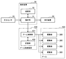
Next, a second embodiment will be described. First, based on FIG. 11, the whole structure of the exclusion apparatus 1 which concerns on 2nd Embodiment is demonstrated. The exclusion device 1 according to the second embodiment is obtained by adding an arm device 400 to the exclusion device 1 according to the first embodiment. The arm device 400 includes an arm 420, and the repellent element 10 is attached to the tip of the arm 420. The arm device 400 and the analysis device 30 are connected by a communication cable 4. These may be wirelessly connected. The operator of the repellent element 10 uses the arm 420 to indirectly operate the repellent element 10.
(2−2.解析装置の構成)
つぎに、図12に基づいて、解析装置30の構成について説明する。解析装置30は、解析部31及び記憶部32を備える。解析部31及び記憶部32の機能は第1の実施形態と同様である。解析部31は、第1の実施形態の処理に加え、圧力値及び上限値をアーム制御部431に出力する処理を行う。
(2-2. Configuration of analysis device)
Next, the configuration of the analysis device 30 will be described with reference to FIG. The analysis device 30 includes an analysis unit 31 and a storage unit 32. The functions of the analysis unit 31 and the storage unit 32 are the same as those in the first embodiment. The analysis unit 31 performs a process of outputting the pressure value and the upper limit value to the arm control unit 431 in addition to the process of the first embodiment.
(2−3.アーム装置の構成)
つぎに、図11及び図12に基づいて、アーム装置400の構成について説明する。アーム装置400は、アーム420及びアーム制御装置430を備える。
(2-3. Configuration of arm device)
Next, the configuration of the arm device 400 will be described with reference to FIGS. 11 and 12. The arm device 400 includes an arm 420 and an arm control device 430.
アーム420は、複数の関節部421a〜421dと、関節部421a〜421d同士を連結される複数のリンク422a〜422dとを有する。もちろん、関節部及びリンクの数は図11の例に限定されない。
The arm 420 includes a plurality of joint portions 421a to 421d and a plurality of links 422a to 422d that connect the joint portions 421a to 421d. Of course, the number of joints and links is not limited to the example of FIG.
リンク422a〜422dは棒状の部材である。リンク422aは、関節部421aと関節部421bとを連結する。ここで、関節部421aはアーム制御装置430に設けられる。また、リンク422bは、関節部421bと関節部421cとを連結する。リンク422cは、関節部421cと関節部421dとを連結する。リンク422dは、関節部421dに設けられている。リンク422dの先端には、圧排子10のグリップ11が固定される。
The links 422a to 422d are rod-shaped members. The link 422a connects the joint part 421a and the joint part 421b. Here, the joint portion 421 a is provided in the arm control device 430. The link 422b connects the joint part 421b and the joint part 421c. The link 422c connects the joint part 421c and the joint part 421d. The link 422d is provided in the joint portion 421d. The grip 11 of the repellent element 10 is fixed to the tip of the link 422d.
関節部421a〜421dの各々には、図12に示す駆動部300が内蔵されている。駆動部300は、例えば、アクチュエータ、トルクセンサ、エンコーダを備える。駆動部300は、さらにブレーキ機構を備えていることが好ましい。関節部421a〜421dは、アクチュエータが駆動されることによって、回転する。そして、関節部421a〜421dの先端側に接続されたリンクは、関節部の回転に連動して回転する。例えば、リンク422aは、関節部421aの回転に連動して回転する。関節部421a〜421dの回転方向は関節部421a〜421d毎に設定される。アクチュエータの動作はアーム制御装置430によって制御される。
Each of the joint portions 421a to 421d incorporates a drive unit 300 shown in FIG. The drive unit 300 includes, for example, an actuator, a torque sensor, and an encoder. The drive unit 300 preferably further includes a brake mechanism. The joint portions 421a to 421d rotate when the actuator is driven. And the link connected to the front end side of joint part 421a-421d rotates in response to rotation of a joint part. For example, the link 422a rotates in conjunction with the rotation of the joint portion 421a. The rotation direction of the joint parts 421a to 421d is set for each joint part 421a to 421d. The operation of the actuator is controlled by the arm control device 430.
トルクセンサは、アクチュエータの出力軸(すなわち、関節部421a〜421dを回転させる軸)に設けられている。トルクセンサは、アクチュエータから出力軸に与えられるトルクを検出することができる他、出力軸に外部から与えられた外力を検出することができる。ここで、外力としては、圧排子10の操作者がアーム420に加えた力、関節部421a〜421dの先端側に設けられたリンク等から与えられるトルク等が挙げられる。トルクセンサの出力値は、アーム制御部431に出力される。エンコーダは、出力軸の回転角度を測定する。エンコーダの出力値は、アーム制御部431に出力される。ブレーキ機構は、例えばアーム420の非通電時に出力軸の回転を停止させる。
The torque sensor is provided on the output shaft of the actuator (that is, the shaft that rotates the joint portions 421a to 421d). The torque sensor can detect torque applied from the actuator to the output shaft, and can detect external force applied to the output shaft from the outside. Here, examples of the external force include a force applied to the arm 420 by the operator of the repellent element 10, torque provided from a link provided on the distal end side of the joint portions 421a to 421d, and the like. The output value of the torque sensor is output to the arm control unit 431. The encoder measures the rotation angle of the output shaft. The output value of the encoder is output to the arm control unit 431. For example, the brake mechanism stops the rotation of the output shaft when the arm 420 is not energized.
アーム制御装置430は、アーム制御部431及び記憶部432を備える。アーム制御部431は、アーム420の動作を制御する。なお、アーム420の制御方式としては、アーム420の操作性を考慮して、好適に力制御が用いられる。具体的には、アーム制御部431は、圧排子10の操作者が直接アーム420に触れて力を加えた場合、アーム420に加えられた力の方向に当該アーム420を移動させる。具体的には、圧排子10の操作者が直接アーム420に触れて力を加えた場合、各関節部421a〜421dに内蔵されたトルクセンサの出力値が変動する。アーム制御部431は、各トルクセンサから与えられた出力値の変動に基づいて、操作者がアーム420に加えた力の方向、大きさを認識する。そして、アーム制御部431は、認識結果に基づいて、各駆動部300を制御する。これにより、アーム420は、アーム420に加えられた力の方向に移動する。
The arm control device 430 includes an arm control unit 431 and a storage unit 432. The arm control unit 431 controls the operation of the arm 420. As a control method of the arm 420, force control is preferably used in consideration of the operability of the arm 420. Specifically, the arm controller 431 moves the arm 420 in the direction of the force applied to the arm 420 when the operator of the repellent element 10 directly touches the arm 420 and applies a force. Specifically, when the operator of the repellent element 10 directly touches the arm 420 and applies force, the output values of the torque sensors built in the joint portions 421a to 421d vary. The arm control unit 431 recognizes the direction and magnitude of the force applied to the arm 420 by the operator based on the fluctuation of the output value given from each torque sensor. Then, the arm control unit 431 controls each driving unit 300 based on the recognition result. As a result, the arm 420 moves in the direction of the force applied to the arm 420.
ここで、第2の実施形態では、圧排子10の圧力値及び上限値がアーム制御部431に与えられる。アーム制御部431は、これらの情報に基づいて、以下の処理を行う。
Here, in the second embodiment, the pressure value and the upper limit value of the repellent element 10 are given to the arm control unit 431. The arm control unit 431 performs the following processing based on these pieces of information.
まず、アーム制御部431は、圧力値の上限値に基づいて、リンク422dが圧排子10に与える力の上限値(以下、この上限値を「アーム力上限値」とも称する)を算出する。例えば、アーム制御部431は、各圧排片15の片面の全面が臓器110に接触すると仮定して、アーム力上限値を算出してもよい。この場合、アーム力上限値は、圧力値の上限値に各圧排片15の片面の総面積を乗じることで得られる。もちろん、アーム力上限値の測定方法はこの例に限られない。
First, the arm control unit 431 calculates an upper limit value of the force that the link 422d applies to the repellent element 10 (hereinafter, this upper limit value is also referred to as an “arm force upper limit value”) based on the upper limit value of the pressure value. For example, the arm control unit 431 may calculate the arm force upper limit value on the assumption that the entire surface of one side of each exclusion piece 15 contacts the organ 110. In this case, the arm force upper limit value is obtained by multiplying the upper limit value of the pressure value by the total area of one side of each of the pressure relief pieces 15. Of course, the measuring method of the arm force upper limit value is not limited to this example.
そして、アーム制御部431は、圧排子10の操作者から与えられる力に基づいてアーム420を駆動させる一方で、関節部421dのトルクセンサから与えられる出力値を監視する。そして、アーム制御部431は、トルクセンサからの出力値がアーム力上限値に達した場合には、それ以上同一方向にはアーム420を動かさない。具体的には、アーム制御部431は、圧排子10の操作者からさらに同一方向の力がアーム420に与えられた場合、逆方向の力をアーム420に発生させる。すなわち、アーム制御部431は、そのような力がアーム420に発生するように、各駆動部300を制御する。これにより、アーム制御部431は、圧力値が上限値に達したことを圧排子10の操作者に提示(この場合は、力覚提示)する。
このように、アーム制御部431は、関節部421dのトルクセンサが検出する外力とアーム力上限値とを対比する。すなわち、アーム制御部431は、関節部421dのトルクセンサが検出する外力に相当する力が、アーム420から臓器110に作用するとみなす。もちろん、アーム力上限値と対比されるパラメータはこの例に限られない。例えば、アーム制御部431は、関節部421b〜421dのトルクセンサから与えられる出力値に基づいて、これらのトルクセンサが検出する外力の合力を算出してもよい。そして、アーム制御部431は、当該合力とアーム力上限値とを対比してもよい。この場合、アーム制御部431は、関節部421b〜421dのトルクセンサが検出する外力の合力に相当する力が、アーム420から臓器110に作用するとみなす。
さらに、アーム制御部431は、アーム力上限値よりも小さい制御発動値を設定し、この制御発動値に基づいて以下の制御を行っても良い。なお、制御発動値の大きさは特に制限されないが、例えばアーム力上限値の60〜80%程度、より具体的には70%程度であっても良い。そして、アーム制御部431は、圧排子10の操作者から与えられる力に基づいてアーム420を駆動させる一方で、関節部421dのトルクセンサから与えられる出力値を監視する。なお、監視対象は上述した合力であってもよい。そして、アーム制御部431は、関節部421dのトルクセンサから与えられる出力値が制御発動値未満となる場合には、圧排子10の操作者から与えられる力に基づいてアーム420を駆動させる。一方、アーム制御部431は、関節部421dのトルクセンサから与えられる出力値が制御発動値以上となる場合には、(トルクセンサからの出力値−制御発動値)に比例した力を圧排子10の操作者による操作方向とは逆方向にアーム420に発生させる。すなわち、アーム制御部431は、そのような力がアーム420に発生するように、各駆動部300を制御する。当該逆方向の力は、(トルクセンサからの出力値−制御発動値)に比例した大きさでなくてもよい。例えば、アーム制御部431は、当該逆方向の力を急峻に発生させても良い。この場合、アーム制御部431は、圧排子10の圧力値が上限値に達する前に、アーム420に反発力を発生させることができる。
Then, the arm control unit 431 drives the arm 420 based on the force given from the operator of the repellent element 10, while monitoring the output value given from the torque sensor of the joint part 421d. When the output value from the torque sensor reaches the arm force upper limit value, the arm control unit 431 does not move the arm 420 in the same direction any more. Specifically, when a force in the same direction is further applied to the arm 420 by the operator of the repellent element 10, the arm control unit 431 generates a force in the reverse direction on the arm 420. That is, the arm control unit 431 controls each driving unit 300 so that such a force is generated in the arm 420. Thereby, the arm control part 431 presents that the pressure value has reached the upper limit value to the operator of the repellent element 10 (in this case, force sense presentation).
Thus, the arm control unit 431 compares the external force detected by the torque sensor of the joint unit 421d with the arm force upper limit value. That is, the arm control unit 431 considers that a force corresponding to the external force detected by the torque sensor of the joint portion 421d acts on the organ 110 from the arm 420. Of course, the parameter compared with the arm force upper limit value is not limited to this example. For example, the arm control unit 431 may calculate the resultant force of the external force detected by these torque sensors based on output values given from the torque sensors of the joint portions 421b to 421d. Then, the arm control unit 431 may compare the resultant force with the arm force upper limit value. In this case, the arm control unit 431 considers that a force corresponding to the resultant force of the external force detected by the torque sensors of the joint portions 421b to 421d acts on the organ 110 from the arm 420.
Furthermore, the arm control unit 431 may set a control activation value smaller than the arm force upper limit value, and perform the following control based on the control activation value. The magnitude of the control activation value is not particularly limited, but may be, for example, about 60 to 80% of the arm force upper limit value, more specifically about 70%. Then, the arm control unit 431 drives the arm 420 based on the force given from the operator of the repellent element 10, while monitoring the output value given from the torque sensor of the joint part 421d. Note that the monitoring target may be the resultant force described above. Then, when the output value given from the torque sensor of the joint part 421d becomes less than the control activation value, the arm control part 431 drives the arm 420 based on the force given from the operator of the repellent element 10. On the other hand, when the output value given from the torque sensor of the joint part 421d is equal to or greater than the control activation value, the arm control unit 431 applies a force proportional to (output value from the torque sensor−control activation value). Is generated in the arm 420 in the direction opposite to the operation direction by the operator. That is, the arm control unit 431 controls each driving unit 300 so that such a force is generated in the arm 420. The force in the reverse direction may not be a magnitude proportional to (output value from torque sensor−control activation value). For example, the arm controller 431 may generate the force in the reverse direction steeply. In this case, the arm control unit 431 can generate a repulsive force in the arm 420 before the pressure value of the repellent element 10 reaches the upper limit value.
これにより、圧排子10の操作者は、圧力値の上限値を意識することなく、アーム420を操作することができる。操作者は、アーム420から反発力が与えられた場合には、圧力値が上限値に達したと把握することができるからである。また、制御発動値を用いた制御が行われる場合、操作者は、圧排子10の圧力値が上限値に達する前に、反発力を認識することができる。さらに、操作者は、反発力を感じた後に、アーム420をさらに同一方向に操作した場合、より大きな反発力を受ける。このため、操作者は、圧力値が上限値に近づいていることをより確実に認識することができる。これにより、第2の実施形態では、圧力値が上限値を超えることをより確実に防止することができる。
Thereby, the operator of the repellent element 10 can operate the arm 420 without being aware of the upper limit value of the pressure value. This is because the operator can grasp that the pressure value has reached the upper limit value when a repulsive force is applied from the arm 420. Further, when control using the control activation value is performed, the operator can recognize the repulsive force before the pressure value of the repellent element 10 reaches the upper limit value. Further, when the operator feels the repulsive force and further operates the arm 420 in the same direction, the operator receives a larger repulsive force. For this reason, the operator can recognize more reliably that the pressure value is approaching the upper limit value. Thereby, in 2nd Embodiment, it can prevent more reliably that a pressure value exceeds an upper limit.
さらに、アーム制御部431は、解析部31から与えられた圧力値が上限値に達したら、上記処理に関わらず、アーム420を緊急停止させてもよい。この際、アーム制御部431は、ブレーキ機構によりアーム420を固定することが好ましい。これにより、圧力値が上限値を超えることをより確実に防止することができる。
Furthermore, when the pressure value given from the analysis unit 31 reaches the upper limit value, the arm control unit 431 may urgently stop the arm 420 regardless of the above processing. At this time, the arm controller 431 preferably fixes the arm 420 by a brake mechanism. Thereby, it can prevent more reliably that a pressure value exceeds an upper limit.
なお、アーム制御部431は、力制御に代えて位置制御を行っても良い。位置制御では、圧排子10の操作者は、何らかの方法(例えば、後述するマスター装置を用いた入力操作)により、アーム420の姿勢を指定する。そして、アーム制御部431は、アーム420の姿勢を操作者が指定した姿勢に一致させる。アーム420の姿勢は、各関節部421a〜421dに設けられたエンコーダからの出力値によって特定される。この場合、アーム制御部431は、圧排子10の位置に基づいて、上述した処理と同様の処理を行うことができる。すなわち、アーム制御部431は、圧排子10が臓器110に接触した後、圧排子10の臓器110側への変位量を測定する。ここで、圧排子10が臓器110に接触したことは、例えば、関節部421dのトルクセンサから与えられる出力値、圧排部13に設けられた圧力センサ20から与えられる出力値等に基づいて判定可能である。圧排子10が臓器110に接触した場合、トルクセンサからの出力値が変動するからである。そして、アーム制御部431は、臓器110にバネ・ダンパモデルを適用し(すなわち、臓器110を弾性体と仮定し)、バネ・ダンパモデルと、圧排子10の臓器110側への変位量とに基づいて、臓器110からの反発力を算出する。この反発力は、リンク422dが圧排子10に与える力に相当する。したがって、アーム制御部431は、臓器110からの反発力がアーム力上限値に達した場合には、それ以上同一方向にはアーム420を動かさないようにする。
The arm control unit 431 may perform position control instead of force control. In the position control, the operator of the repellent element 10 designates the posture of the arm 420 by some method (for example, an input operation using a master device described later). Then, the arm control unit 431 matches the posture of the arm 420 with the posture specified by the operator. The posture of the arm 420 is specified by output values from the encoders provided in the joint portions 421a to 421d. In this case, the arm control unit 431 can perform the same processing as the above-described processing based on the position of the repellent element 10. That is, the arm control unit 431 measures the displacement amount of the retraction element 10 toward the organ 110 after the retraction element 10 contacts the organ 110. Here, it is possible to determine that the retraction element 10 has contacted the organ 110 based on, for example, an output value given from the torque sensor of the joint part 421d, an output value given from the pressure sensor 20 provided in the exclusion part 13 or the like. It is. This is because the output value from the torque sensor varies when the repellent element 10 contacts the organ 110. Then, the arm control unit 431 applies a spring / damper model to the organ 110 (that is, the organ 110 is assumed to be an elastic body), and the displacement of the retraction element 10 toward the organ 110 is determined. Based on this, the repulsive force from the organ 110 is calculated. This repulsive force corresponds to the force that the link 422d applies to the repellent element 10. Therefore, when the repulsive force from the organ 110 reaches the arm force upper limit value, the arm control unit 431 prevents the arm 420 from moving further in the same direction.
記憶部432は、アーム制御装置430の動作に必要な情報、例えばプログラム等を記憶する。アーム制御装置430は、例えばCPU(Central Processing Unit)やDSP(Digital Signal Processor)等のプロセッサ、又はこれらのプロセッサが搭載されたマイコン等によって構成されうる。そして、プロセッサが所定のプログラムに従った信号処理及び制御処理を実行することにより、アーム制御装置430の処理が実行される。
The storage unit 432 stores information necessary for the operation of the arm control device 430, such as a program. The arm control device 430 can be configured by a processor such as a CPU (Central Processing Unit) and a DSP (Digital Signal Processor), or a microcomputer on which these processors are mounted. Then, when the processor executes signal processing and control processing according to a predetermined program, the processing of the arm control device 430 is executed.
(2−4.使用例)
次に、図11に基づいて、圧排装置1の使用例を説明する。この使用例でも、第1の実施形態と同様に、圧排装置1を低侵襲手術に使用する。ただし、圧排子10の操作者は、アーム420を用いて圧排子10を操作する。具体的には、圧排子10の操作者は、患者の腹部の皮膚100にトロッカ60(円筒状の部材)を通す。これにより、皮膚100に開口が形成される。ついで、圧排子10の操作者は、アーム420を操作することで圧排子10をトロッカ60近傍まで移動させる。ついで、操作者は、トロッカ60を通して圧排子10を患者の体内に挿入する。
(2-4. Usage example)
Next, the usage example of the exclusion apparatus 1 is demonstrated based on FIG. Also in this use example, the retraction device 1 is used for minimally invasive surgery as in the first embodiment. However, the operator of the repellent element 10 operates the repellent element 10 using the arm 420. Specifically, the operator of the retraction element 10 passes the trocar 60 (cylindrical member) through the skin 100 of the patient's abdomen. Thereby, an opening is formed in the skin 100. Next, the operator of the repellent element 10 moves the repellent element 10 to the vicinity of the trocar 60 by operating the arm 420. Next, the operator inserts the retraction element 10 through the trocar 60 into the patient's body.
圧排子10の操作者は、表示装置50に表示された撮像画像を参照しながら、圧排部13を圧排対象の臓器110に接触させる。その後、圧排子10の操作者は、圧排部13を用いて臓器110を圧排する。一方、圧力センサ20は、圧排部13が臓器110に与えある圧力を検出する。そして、圧力センサ20は、圧力値に相当する出力値を解析装置30に出力する。その後の解析部31は、第1の実施形態と同様の処理を行う。例えば、解析部31は、圧力値及び上限値を表示装置50に表示させる。さらに、解析部31は、圧力値及び上限値をアーム制御部431に出力する。
The operator of the retraction element 10 brings the exclusion part 13 into contact with the organ 110 to be excluded while referring to the captured image displayed on the display device 50. Thereafter, the operator of the retraction element 10 uses the retraction unit 13 to relieve the organ 110. On the other hand, the pressure sensor 20 detects the pressure that the exclusion unit 13 applies to the organ 110. Then, the pressure sensor 20 outputs an output value corresponding to the pressure value to the analysis device 30. The subsequent analysis unit 31 performs the same processing as in the first embodiment. For example, the analysis unit 31 displays the pressure value and the upper limit value on the display device 50. Further, the analysis unit 31 outputs the pressure value and the upper limit value to the arm control unit 431.
そして、アーム制御部431は、圧排子10の操作者による操作に応じてアーム420を駆動させる一方で、関節部421dのトルクセンサから与えられる出力値を監視する。そして、アーム制御部431は、トルクセンサからの出力値がアーム力上限値に達した場合には、それ以上同一方向にはアーム420を動かさない。具体的には、アーム制御部431は、圧排子10の操作者からさらに同一方向の力がアーム420に与えられた場合、逆方向の力をアーム420に発生させる。すなわち、アーム制御部431は、そのような力がアーム420に発生するように、各駆動部300を制御する。すなわち、アーム制御部431は、圧力値が上限値に達したことを圧排子10の操作者に提示(この場合は、力覚提示)する。したがって、操作者は、圧力値の上限値を意識することなく、アーム420を操作することができる。
The arm control unit 431 monitors the output value given from the torque sensor of the joint portion 421d while driving the arm 420 according to the operation of the operator of the repellent element 10. When the output value from the torque sensor reaches the arm force upper limit value, the arm control unit 431 does not move the arm 420 in the same direction any more. Specifically, when a force in the same direction is further applied to the arm 420 by the operator of the repellent element 10, the arm control unit 431 generates a force in the reverse direction on the arm 420. That is, the arm control unit 431 controls each driving unit 300 so that such a force is generated in the arm 420. That is, the arm control unit 431 presents to the operator of the repressor 10 that the pressure value has reached the upper limit value (in this case, a force sense is presented). Therefore, the operator can operate the arm 420 without being aware of the upper limit value of the pressure value.
第2の実施形態によれば、圧排装置1は、アーム420を備える。したがって、圧排子10の操作者は、アーム420を操作することで、圧排子10を間接的に操作することができる。
According to the second embodiment, the exclusion device 1 includes the arm 420. Therefore, the operator of the repellent element 10 can indirectly operate the repellent element 10 by operating the arm 420.
さらに、アーム制御部431は、圧力値及び上限値に基づいて、アーム420を制御する。具体的には、アーム制御部431は、圧力値が上限値以下になるように、アーム420を制御する。したがって、圧力値が上限値を超えることをより確実に防止することができる。さらに、アーム制御部431は、圧力値が上限値に達した場合には、アーム420を介してその旨を操作者に提示する。具体的には、アーム制御部431は、アーム420に反発力を発生させることで、力覚提示を行う。これにより、操作者は、圧力値の上限値を意識することなく、アーム420を操作することができる。さらに、表示装置50には、第1の実施形態と同様の内容が表示される。したがって、操作者は、圧排をより安全に行うことができる。
Furthermore, the arm control unit 431 controls the arm 420 based on the pressure value and the upper limit value. Specifically, the arm control unit 431 controls the arm 420 so that the pressure value is equal to or lower than the upper limit value. Therefore, it can prevent more reliably that a pressure value exceeds an upper limit. Further, when the pressure value reaches the upper limit value, the arm control unit 431 notifies the operator via the arm 420. Specifically, the arm control unit 431 performs force sense presentation by causing the arm 420 to generate a repulsive force. Thus, the operator can operate the arm 420 without being aware of the upper limit value of the pressure value. Further, the display device 50 displays the same content as in the first embodiment. Therefore, the operator can perform the exclusion more safely.
<3.第3の実施形態>
(3−1.圧排装置の全体構成)
つぎに、第3の実施形態について説明する。まず、図13に基づいて、第3の実施形態に係る圧排装置1の全体構成について説明する。第3の実施形態に係る圧排装置1は、第2の実施形態に係る圧排装置1にマスター装置500を追加したものである。マスター装置500とアーム制御装置430とは、通信ケーブル5で接続されている。これらは無線接続されていてもよい。マスター装置500は、アーム420の操作に使用される。すなわち、圧排子10の操作者Uは、アーム420に触れることでアーム420を直接操作してもよいし、マスター装置500を用いてアーム420を間接的に操作してもよい。
<3. Third Embodiment>
(3-1. Overall Configuration of Exclusion Device)
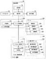
Next, a third embodiment will be described. First, based on FIG. 13, the whole structure of the exclusion apparatus 1 which concerns on 3rd Embodiment is demonstrated. The exclusion device 1 according to the third embodiment is obtained by adding a master device 500 to the exclusion device 1 according to the second embodiment. Master device 500 and arm control device 430 are connected by communication cable 5. These may be wirelessly connected. Master device 500 is used to operate arm 420. That is, the operator U of the repellent element 10 may directly operate the arm 420 by touching the arm 420 or may indirectly operate the arm 420 using the master device 500.
(3−2.解析装置の構成)
つぎに、図14に基づいて、解析装置30の構成について説明する。解析装置30は、解析部31及び記憶部32を備える。解析部31及び記憶部32の機能は第2の実施形態と同様である。なお、解析部31は、圧力値及び上限値をマスター制御部511に出力してもよい。
(3-2. Configuration of analysis apparatus)
Next, the configuration of the analysis device 30 will be described with reference to FIG. The analysis device 30 includes an analysis unit 31 and a storage unit 32. The functions of the analysis unit 31 and the storage unit 32 are the same as those in the second embodiment. The analysis unit 31 may output the pressure value and the upper limit value to the master control unit 511.
(3−3.アーム装置の構成)
つぎに、図13及び図14に基づいて、アーム装置400の構成について説明する。アーム装置400は、アーム420及びアーム制御装置430を備える。アーム420及びアーム制御装置430の構成及び機能は第2の実施形態と同様である。さらに、アーム制御部431は、以下の処理を行うことが可能である。
(3-3. Configuration of arm device)
Next, the configuration of the arm device 400 will be described with reference to FIGS. 13 and 14. The arm device 400 includes an arm 420 and an arm control device 430. The configurations and functions of the arm 420 and the arm control device 430 are the same as those in the second embodiment. Furthermore, the arm control unit 431 can perform the following processing.
すなわち、アーム制御部431は、マスター制御部511から与えられた操作情報に基づいて、アーム420を制御する。制御方式は力制御であっても、位置制御であってもよい。力制御の場合、操作情報は、圧排子10の操作者が入力操作用アーム520に加えた力の大きさ及び方向に関する情報を含む。位置制御の場合、入力操作用アーム520の姿勢に関する情報を含む。
That is, the arm control unit 431 controls the arm 420 based on the operation information given from the master control unit 511. The control method may be force control or position control. In the case of force control, the operation information includes information related to the magnitude and direction of the force applied to the input operation arm 520 by the operator of the retraction element 10. In the case of position control, information on the posture of the input operation arm 520 is included.
さらに、アーム制御部431は、圧力値が上限値に達した場合には、それ以上同一方向にはアーム420を動かさない。さらに、アーム制御部431は、圧力値が上限値に達した旨を操作者に提示することを指示する提示指示情報をマスター制御部511に出力する。
Furthermore, when the pressure value reaches the upper limit value, the arm control unit 431 does not move the arm 420 in the same direction any more. Further, the arm control unit 431 outputs presentation instruction information for instructing the operator that the pressure value has reached the upper limit value, to the master control unit 511.
(3−4.マスター装置の構成)
つぎに、図13及び図14に基づいて、マスター装置500の構成について説明する。マスター装置500は、入力操作用アーム520及びマスター制御装置510を備える。
(3-4. Configuration of master device)
Next, the configuration of the master device 500 will be described with reference to FIGS. 13 and 14. The master device 500 includes an input operation arm 520 and a master control device 510.
入力操作用アーム520は、複数の関節部521a〜521dと、関節部521a〜521d同士を連結される複数のリンク522a〜522dとを有する。もちろん、関節部及びリンクの数は図13の例に限定されない。すなわち、入力操作用アーム520は、アーム420を縮小させた形状を有している。したがって、関節部521a〜521d及びリンク522a〜522dの機能は、関節部421a〜421d及びリンク422a〜422dとほぼ同様である。
The input operation arm 520 includes a plurality of joint portions 521a to 521d and a plurality of links 522a to 522d that connect the joint portions 521a to 521d. Of course, the number of joints and links is not limited to the example of FIG. That is, the input operation arm 520 has a shape in which the arm 420 is reduced. Accordingly, the functions of the joint portions 521a to 521d and the links 522a to 522d are substantially the same as those of the joint portions 421a to 421d and the links 422a to 422d.
すなわち、リンク522a〜522dは棒状の部材である。リンク522aは、関節部521aと関節部521bとを連結する。ここで、関節部521aはマスター制御装置510に設けられる。また、リンク522bは、関節部521bと関節部521cとを連結する。リンク522cは、関節部521cと関節部521dとを連結する。リンク522dは、関節部521dに設けられている。
That is, the links 522a to 522d are rod-shaped members. The link 522a connects the joint part 521a and the joint part 521b. Here, the joint portion 521 a is provided in the master control device 510. The link 522b connects the joint part 521b and the joint part 521c. The link 522c connects the joint part 521c and the joint part 521d. The link 522d is provided in the joint portion 521d.
関節部521a〜521dの各々には、図14に示す操作駆動部600が内蔵されている。操作駆動部600は、例えばアクチュエータ、トルクセンサ、エンコーダを備える。関節部521a〜521dは、アクチュエータが駆動されることによって、回転する。そして、関節部521a〜521dの先端側に接続されたリンクは、関節部の回転に連動して回転する。例えば、リンク522aは、関節部521aの回転に連動して回転する。関節部521a〜521dの回転方向は関節部421a〜421dに対応する。アクチュエータの動作はマスター制御部511によって制御される。
Each of the joint portions 521a to 521d has a built-in operation driving portion 600 shown in FIG. The operation drive unit 600 includes, for example, an actuator, a torque sensor, and an encoder. The joint portions 521a to 521d rotate when the actuator is driven. And the link connected to the front end side of joint part 521a-521d rotates in response to rotation of a joint part. For example, the link 522a rotates in conjunction with the rotation of the joint portion 521a. The rotation directions of the joint portions 521a to 521d correspond to the joint portions 421a to 421d. The operation of the actuator is controlled by the master control unit 511.
トルクセンサは、アクチュエータの出力軸(すなわち、関節部521a〜521dを回転させる軸)に設けられている。トルクセンサは、アクチュエータから出力軸に与えられるトルクを検出することができる他、出力軸に外部から与えられた外力を検出することができる。ここで、外力としては、圧排子10の操作者が入力操作用アーム520に加えた力、関節部521a〜521dの先端側に設けられたリンク等から与えられるトルク等が挙げられる。トルクセンサの出力値は、マスター制御部511に出力される。エンコーダは、出力軸の回転角度を測定する。エンコーダの出力値は、マスター制御部511に出力される。また、関節部521a〜521dには、アーム420と同様のブレーキ機構が設けられていてもよい。
The torque sensor is provided on the output shaft of the actuator (that is, the shaft that rotates the joint portions 521a to 521d). The torque sensor can detect torque applied from the actuator to the output shaft, and can detect external force applied to the output shaft from the outside. Here, examples of the external force include a force applied to the input operation arm 520 by the operator of the repellent element 10, a torque provided from a link provided on the distal end side of the joint portions 521a to 521d, and the like. The output value of the torque sensor is output to the master control unit 511. The encoder measures the rotation angle of the output shaft. The output value of the encoder is output to the master control unit 511. Further, the joint portions 521a to 521d may be provided with a brake mechanism similar to the arm 420.
マスター制御装置510は、マスター制御部511及び記憶部512を備える。マスター制御部511は、入力操作用アーム520の動作を制御する。なお、入力操作用アーム520の制御方式としては、好適に力制御が用いられる。具体的には、マスター制御部511は、圧排子10の操作者が入力操作用アーム520に触れて力を加えた場合、入力操作用アーム520に加えられた力の方向に当該入力操作用アーム520を移動させる。具体的な制御方法はアーム装置400と同様である。さらに、マスター制御部511は、操作者が入力操作用アーム520に加えた力の大きさ及び方向に関する操作情報を生成し、アーム制御部431に出力する。これにより、アーム制御部431は、アーム420を力制御することができる。
The master control device 510 includes a master control unit 511 and a storage unit 512. The master control unit 511 controls the operation of the input operation arm 520. Note that force control is preferably used as the control method of the input operation arm 520. Specifically, when the operator of the repellent element 10 touches the input operation arm 520 and applies a force, the master control unit 511 moves the input operation arm in the direction of the force applied to the input operation arm 520. 520 is moved. A specific control method is the same as that of the arm device 400. Further, the master control unit 511 generates operation information regarding the magnitude and direction of the force applied by the operator to the input operation arm 520 and outputs the operation information to the arm control unit 431. As a result, the arm control unit 431 can control the force of the arm 420.
なお、マスター制御部511は、操作情報として、入力操作用アーム520の姿勢(より具体的には、関節部521a〜521d内のエンコーダの値)をアーム制御部431に出力してもよい。この場合、アーム制御部431は、アーム420を位置制御することができる。
Note that the master control unit 511 may output the posture of the input operation arm 520 (more specifically, the value of the encoder in the joint units 521a to 521d) to the arm control unit 431 as operation information. In this case, the arm control unit 431 can control the position of the arm 420.
さらに、マスター制御部511は、アーム制御部431から提示指示情報が与えられた場合、圧力値が上限値に達したことを、入力操作用アーム520を介して操作者に提示する。これにより、アーム制御部431は、圧力値が上限値に達したことを、入力操作用アーム520を介して操作者に提示することができる。例えば、マスター制御部511は、操作駆動部600を制御することで、入力操作用アーム520を振動させる。すなわち、マスター制御部511は、圧力値が上限値に達したことを圧排子10の操作者に提示(この場合は、力覚提示)する。なお、アーム420と同様に、操作方向と逆方向の力を入力操作用アーム520に発生させても良い。
Further, when the presentation instruction information is given from the arm control unit 431, the master control unit 511 presents to the operator via the input operation arm 520 that the pressure value has reached the upper limit value. Thereby, the arm control part 431 can show an operator that the pressure value has reached the upper limit value via the input operation arm 520. For example, the master control unit 511 controls the operation driving unit 600 to vibrate the input operation arm 520. That is, the master control unit 511 presents that the pressure value has reached the upper limit value to the operator of the repellent element 10 (in this case, a force sense presentation). Similar to the arm 420, a force in the direction opposite to the operation direction may be generated in the input operation arm 520.
これにより、圧排子10の操作者は、圧力値の上限値を意識することなく、アーム420を操作することができる。操作者は、入力操作用アーム520が振動した場合、あるいは、入力操作用アーム520から逆方向の力(すなわち、反発力)を受けた場合には、圧力値が上限値に達したと把握することができるからである。これにより、第3の実施形態では、圧力値が上限値を超えることをより確実に防止することができる。
Thereby, the operator of the repellent element 10 can operate the arm 420 without being aware of the upper limit value of the pressure value. The operator grasps that the pressure value has reached the upper limit when the input operation arm 520 vibrates or receives a reverse force (ie, repulsive force) from the input operation arm 520. Because it can. Thereby, in 3rd Embodiment, it can prevent more reliably that a pressure value exceeds an upper limit.
さらに、マスター制御部511は、解析部31から与えられた圧力値が上限値に達したら、アーム制御部431から提示指示情報が当たられたか否かに関わらず、入力操作用アーム520を振動させてもよい。これにより、圧力値が上限値を超えることをより確実に防止することができる。
Furthermore, when the pressure value given from the analysis unit 31 reaches the upper limit value, the master control unit 511 vibrates the input operation arm 520 regardless of whether the presentation instruction information is received from the arm control unit 431 or not. May be. Thereby, it can prevent more reliably that a pressure value exceeds an upper limit.
記憶部512は、マスター制御装置510の動作に必要な情報、例えばプログラム等を記憶する。マスター制御装置510は、例えばCPU(Central Processing Unit)やDSP(Digital Signal Processor)等のプロセッサ、又はこれらのプロセッサが搭載されたマイコン等によって構成されうる。そして、プロセッサが所定のプログラムに従った信号処理及び制御処理を実行することにより、マスター制御装置510の処理が実行される。
The storage unit 512 stores information necessary for the operation of the master control device 510, such as a program. The master control device 510 can be configured by a processor such as a CPU (Central Processing Unit) and a DSP (Digital Signal Processor), or a microcomputer on which these processors are mounted. Then, when the processor executes signal processing and control processing according to a predetermined program, processing of the master control device 510 is executed.
なお、マスター装置500の構成は図13及び図14の例に限定されない。マスター装置500は、アーム420を操作できるものであればどのようなものであっても良い。例えば、マスター装置500は、操作レバーを有するものであっても良い。また、入力操作用アーム520は操作駆動部600を有していなくてもよい。この場合、入力操作用アーム520は、その姿勢に関する情報を出力でき、かつ、なんらかの駆動(上述した振動等)ができればよい。すなわち、関節部521a〜521dはエンコーダ及び何らかの駆動装置(例えば、振動が可能な駆動装置)を有していればよい。この場合、マスター制御部511は、操作情報として入力操作用アーム520の姿勢に関する情報をアーム制御部431に出力する。
Note that the configuration of the master device 500 is not limited to the examples of FIGS. 13 and 14. The master device 500 may be any device that can operate the arm 420. For example, the master device 500 may have an operation lever. Further, the input operation arm 520 may not include the operation driving unit 600. In this case, the input operation arm 520 only needs to be able to output information related to its posture and perform some kind of driving (vibration or the like described above). That is, the joint portions 521a to 521d only need to have an encoder and some kind of driving device (for example, a driving device capable of vibration). In this case, the master control unit 511 outputs information regarding the posture of the input operation arm 520 to the arm control unit 431 as operation information.
(3−5.使用例)
次に、図13に基づいて、圧排装置1の使用例を説明する。この使用例でも、第1の実施形態と同様に、圧排装置1を低侵襲手術に使用する。ただし、圧排子10の操作者は、アーム420を用いて圧排子10を操作する。操作者は、アーム420を触れることでアーム420を直接操作してもよいし、マスター装置500を用いてアーム420を間接的に操作してもよい。具体的には、圧排子10の操作者は、患者の腹部の皮膚100にトロッカ60(円筒状の部材)を通す。これにより、皮膚100に開口が形成される。ついで、圧排子10の操作者は、アーム420を操作することで圧排子10をトロッカ60近傍まで移動させる。ついで、操作者は、トロッカ60を通して圧排子10を患者の体内に挿入する。
(3-5. Usage example)
Next, the usage example of the exclusion apparatus 1 is demonstrated based on FIG. Also in this use example, the retraction device 1 is used for minimally invasive surgery as in the first embodiment. However, the operator of the repellent element 10 operates the repellent element 10 using the arm 420. The operator may directly operate the arm 420 by touching the arm 420 or may indirectly operate the arm 420 using the master device 500. Specifically, the operator of the retraction element 10 passes the trocar 60 (cylindrical member) through the skin 100 of the patient's abdomen. Thereby, an opening is formed in the skin 100. Next, the operator of the repellent element 10 moves the repellent element 10 to the vicinity of the trocar 60 by operating the arm 420. Next, the operator inserts the retraction element 10 through the trocar 60 into the patient's body.
圧排子10の操作者は、表示装置50に表示された撮像画像を参照しながら、圧排部13を圧排対象の臓器110に接触させる。その後、圧排子10の操作者は、圧排部13を用いて臓器110を圧排する。一方、圧力センサ20は、圧排部13が臓器110に与えある圧力を検出する。そして、圧力センサ20は、圧力値に相当する出力値を解析装置30に出力する。その後の解析部31は、第2の実施形態と同様の処理を行う。例えば、解析部31は、圧力値及び上限値を表示装置50に表示させる。さらに、解析部31は、圧力値及び上限値をアーム制御部431に出力する。
The operator of the retraction element 10 brings the exclusion part 13 into contact with the organ 110 to be excluded while referring to the captured image displayed on the display device 50. Thereafter, the operator of the retraction element 10 uses the retraction unit 13 to relieve the organ 110. On the other hand, the pressure sensor 20 detects the pressure that the exclusion unit 13 applies to the organ 110. Then, the pressure sensor 20 outputs an output value corresponding to the pressure value to the analysis device 30. The subsequent analysis unit 31 performs the same processing as in the second embodiment. For example, the analysis unit 31 displays the pressure value and the upper limit value on the display device 50. Further, the analysis unit 31 outputs the pressure value and the upper limit value to the arm control unit 431.
そして、アーム制御部431は、圧排子10の操作者による操作に応じてアーム420を駆動させる。この操作は、上述したように、アーム420に対して直接行われる場合もあるし、マスター装置500を用いて間接的に行われる場合もある。マスター装置500が用いられる場合、マスター装置500は、操作情報をアーム制御部431に出力する。アーム制御部431は、この一方で、関節部421dのトルクセンサから与えられる出力値を監視する。そして、アーム制御部431は、トルクセンサからの出力値がアーム力上限値に達した場合には、それ以上同一方向にはアーム420を動かさない。さらに、アーム制御部431は、提示指示情報をマスター制御部511に出力する。マスター制御部511は、提示指示情報が与えられた場合、入力操作用アーム520を振動させる。なお、アーム420が直接操作される場合もあるので、アーム制御部431は、第2の実施形態と同様に、アーム420に反発力を発生させても良い。したがって、操作者は、圧力値の上限値を意識することなく、アーム420を操作することができる。
Then, the arm control unit 431 drives the arm 420 in accordance with the operation of the repellent element 10 by the operator. As described above, this operation may be performed directly on the arm 420 or may be performed indirectly using the master device 500. When the master device 500 is used, the master device 500 outputs operation information to the arm control unit 431. On the other hand, the arm controller 431 monitors the output value given from the torque sensor of the joint 421d. When the output value from the torque sensor reaches the arm force upper limit value, the arm control unit 431 does not move the arm 420 in the same direction any more. Further, the arm control unit 431 outputs presentation instruction information to the master control unit 511. When the presentation instruction information is given, the master control unit 511 vibrates the input operation arm 520. Since the arm 420 may be directly operated, the arm control unit 431 may generate a repulsive force in the arm 420 as in the second embodiment. Therefore, the operator can operate the arm 420 without being aware of the upper limit value of the pressure value.
第3の実施形態によれば、アーム制御部431は、マスター制御部511から与えられた操作情報に基づいて、アーム420を制御する。さらに、アーム制御部431は、圧力値が上限値に到達したことを、入力操作用アーム520を介して提示することができる。これにより、操作者は、圧力値の上限値を意識することなく、アーム420を操作することができる。さらに、表示装置50には、第1の実施形態と同様の内容が表示される。したがって、操作者は、圧排をより安全に行うことができる。
According to the third embodiment, the arm control unit 431 controls the arm 420 based on the operation information given from the master control unit 511. Furthermore, the arm control unit 431 can present via the input operation arm 520 that the pressure value has reached the upper limit value. Thus, the operator can operate the arm 420 without being aware of the upper limit value of the pressure value. Further, the display device 50 displays the same content as in the first embodiment. Therefore, the operator can perform the exclusion more safely.
以上、添付図面を参照しながら本開示の好適な実施形態について詳細に説明したが、本開示の技術的範囲はかかる例に限定されない。本開示の技術分野における通常の知識を有する者であれば、特許請求の範囲に記載された技術的思想の範疇内において、各種の変更例または修正例に想到し得ることは明らかであり、これらについても、当然に本開示の技術的範囲に属するものと了解される。
The preferred embodiments of the present disclosure have been described in detail above with reference to the accompanying drawings, but the technical scope of the present disclosure is not limited to such examples. It is obvious that a person having ordinary knowledge in the technical field of the present disclosure can come up with various changes or modifications within the scope of the technical idea described in the claims. Of course, it is understood that it belongs to the technical scope of the present disclosure.
また、本明細書に記載された効果は、あくまで説明的または例示的なものであって限定的ではない。つまり、本開示に係る技術は、上記の効果とともに、または上記の効果に代えて、本明細書の記載から当業者には明らかな他の効果を奏しうる。
Further, the effects described in the present specification are merely illustrative or exemplary and are not limited. That is, the technology according to the present disclosure can exhibit other effects that are apparent to those skilled in the art from the description of the present specification in addition to or instead of the above effects.
なお、以下のような構成も本開示の技術的範囲に属する。
(1)
人体の臓器を圧排する圧排部と、
前記圧排部に設けられ、前記圧排部と前記人体の臓器との接触状態を検出する検出部と、を備える圧排子。
(2)
前記検出部は、前記接触状態として、前記圧排部が前記人体の臓器から受ける圧力を検出する、前記(1)記載の圧排子。
(3)
前記(2)記載の圧排子と、
前記検出部が出力した出力値を解析する解析部と、を備える、圧排装置。
(4)
前記解析部は、前記解析によって得られた圧力値を提示する制御を行う、前記(3)記載の圧排装置。
(5)
前記解析部は、前記圧力値の上限値を提示する制御を行う、前記(4)記載の圧排装置。
(6)
前記解析部は、前記圧力値と前記圧力値の上限値とを対比して提示する制御を行う、前記(5)記載の圧排装置。
(7)
前記解析部は、前記解析によって得られた圧力値の変化を提示する制御を行う、前記(4)〜(6)の何れか1項に記載の圧排装置。
(8)
前記解析部は、前記圧力値の経時変化を提示する制御を行う、前記(7)記載の圧排装置。
(9)
前記解析部は、前記圧力値の分布を提示する制御を行う、前記(7)または(8)に記載の圧排装置。
(10)
前記解析によって得られた圧力値を記憶する記憶部をさらに備える、前記(3)〜(9)の何れか1項に記載の圧排装置。
(11)
前記圧排子を保持するアームを備える、前記(3)〜(10)の何れか1項に記載の圧排装置。
(12)
前記解析部による解析により得られた圧力値に基づいて、前記アームを制御する制御部を備える、前記(11)記載の圧排装置。
(13)
前記制御部は、前記圧力値が前記圧力値の上限値以下となるように、前記アームを制御する、前記(12)記載の圧排装置。
(14)
前記制御部は、前記圧力値が前記圧力値の上限値に到達した場合には、前記圧力値が前記圧力値の上限値に到達したことを、前記アームを介して提示する、前記(13)記載の圧排装置。
(15)
前記制御部は、前記圧力値が前記圧力値の上限値に到達した場合には、前記アームを停止するよう制御する、前記(13)または(14)記載の圧排装置。
(16)
前記制御部は、入力操作部から与えられた操作情報に基づいて、前記アームを制御する、前記(12)〜(15)の何れか1項に記載の圧排装置。
(17)
前記制御部は、前記圧力値が前記圧力値の上限値に到達した場合には、前記圧力値が前記圧力値の上限値に到達したことを、前記入力操作部を介して提示する、前記(16)記載の圧排装置。
(18)
前記制御部は、前記アームを力制御する、前記(12)〜(17)の何れか1項に記載の圧排装置。
The following configurations also belong to the technical scope of the present disclosure.
(1)
An exclusion part that excludes human organs;
An exclusion device provided in the exclusion portion, and comprising a detection portion that detects a contact state between the exclusion portion and the organ of the human body.
(2)
The extruding element according to (1), wherein the detecting unit detects, as the contact state, a pressure that the excluding unit receives from the organ of the human body.
(3)
Extruder as described in (2) above,
An exclusion device, comprising: an analysis unit that analyzes an output value output by the detection unit.
(4)
The exclusion device according to (3), wherein the analysis unit performs control to present a pressure value obtained by the analysis.
(5)
The relieving device according to (4), wherein the analysis unit performs control to present an upper limit value of the pressure value.
(6)
The said analysis part is an exclusion apparatus of the said (5) description which performs control which compares and presents the said pressure value and the upper limit of the said pressure value.
(7)
The exclusion device according to any one of (4) to (6), wherein the analysis unit performs control to present a change in a pressure value obtained by the analysis.
(8)
The exclusion device according to (7), wherein the analysis unit performs control to present a change with time of the pressure value.
(9)
The said analysis part is an exclusion apparatus as described in said (7) or (8) which performs control which shows distribution of the said pressure value.
(10)
The exclusion apparatus according to any one of (3) to (9), further including a storage unit that stores a pressure value obtained by the analysis.
(11)
The exclusion apparatus according to any one of (3) to (10), further including an arm that holds the exclusion element.
(12)
The exclusion apparatus according to (11), further including a control unit that controls the arm based on a pressure value obtained by analysis by the analysis unit.
(13)
The exclusion device according to (12), wherein the control unit controls the arm so that the pressure value is equal to or less than an upper limit value of the pressure value.
(14)
When the pressure value reaches the upper limit value of the pressure value, the control unit presents, via the arm, that the pressure value has reached the upper limit value of the pressure value, (13) The described exclusion device.
(15)
The control device according to (13) or (14), wherein the control unit controls to stop the arm when the pressure value reaches an upper limit value of the pressure value.
(16)
The said control part is an exclusion apparatus of any one of said (12)-(15) which controls the said arm based on the operation information given from the input operation part.
(17)
When the pressure value reaches the upper limit value of the pressure value, the control unit presents, via the input operation unit, that the pressure value has reached the upper limit value of the pressure value. 16) The exclusion apparatus as described.
(18)
The exclusion device according to any one of (12) to (17), wherein the control unit controls the force of the arm.