JP2017123743A - Stator for electric motor - Google Patents
Stator for electric motor Download PDFInfo
- Publication number
- JP2017123743A JP2017123743A JP2016002179A JP2016002179A JP2017123743A JP 2017123743 A JP2017123743 A JP 2017123743A JP 2016002179 A JP2016002179 A JP 2016002179A JP 2016002179 A JP2016002179 A JP 2016002179A JP 2017123743 A JP2017123743 A JP 2017123743A
- Authority
- JP
- Japan
- Prior art keywords
- teeth
- insulating member
- stator
- stator core
- portions
- Prior art date
- Legal status (The legal status is an assumption and is not a legal conclusion. Google has not performed a legal analysis and makes no representation as to the accuracy of the status listed.)
- Pending
Links
Images


Landscapes
- Insulation, Fastening Of Motor, Generator Windings (AREA)
Abstract
【課題】絶縁部材をティースにより確実に固定する。【解決手段】絶縁部材44は、互いに隣り合うティース24の間に位置するステータコアの内周面を覆う背部44aと、背部44aの周方向における両端部から延出しティース24の対応する一方の側面を覆う側部44と、側部44のステータコア22の軸方向において同じ方向の端部から延出しティース24の対応する軸方向の端面の一部を覆うフランジ部44d,44eと、を有し、隣のスロット26に配置された絶縁部材44と、フランジ部44d,44eが互い違いとなるように配置されている。そして、固定部材46に、挟み込み部46b,46cを設け、挟み込み部46b,46cによりティース24の両端面のフランジ部44d,44eを外側から挟み込む。これにより、絶縁部材44をティース24により確実に固定することができる。【選択図】図2An insulating member is securely fixed by a tooth. An insulating member 44 includes a back portion 44a covering an inner peripheral surface of a stator core positioned between adjacent teeth 24, and one side surface corresponding to a tooth 24 extending from both ends in the circumferential direction of the back portion 44a. A side portion 44 to be covered, and flange portions 44d and 44e extending from end portions in the same direction in the axial direction of the stator core 22 of the side portion 44 and covering a part of the corresponding end surfaces in the axial direction of the teeth 24. The insulating member 44 disposed in the slot 26 and the flange portions 44d and 44e are disposed alternately. Then, sandwiching portions 46b and 46c are provided in the fixing member 46, and the flange portions 44d and 44e on both end faces of the tooth 24 are sandwiched from outside by the sandwiching portions 46b and 46c. Thereby, the insulating member 44 can be reliably fixed by the teeth 24. [Selection] Figure 2
Description
本発明は、電動機用ステータに関する。 The present invention relates to a stator for an electric motor.
従来、この種の電動機用ステータとしては、ステータコアと、第1,第2の絶縁部材と、を備えるものが提案されている(例えば、特許文献1参照)。ステータコアは、コイルが巻き回される複数のティース部を備えている。第1の絶縁部材は、ティース部の側面に密着するように配置されている。第2の絶縁部材は、ステータコアの軸方向の端面に配置されている。第1,第2の絶縁部材は、ステータコアとコイルとの間に配置され、ステータコアとコイルとを絶縁している。この電動機用ステータでは、第2の絶縁部材を第1の絶縁部材と段差無く接するように配置することにより、第1の絶縁部材と第2の絶縁部材とが接する部分でコイルが引っかかることを抑制している。 Conventionally, as this kind of stator for an electric motor, one having a stator core and first and second insulating members has been proposed (for example, see Patent Document 1). The stator core includes a plurality of teeth portions around which a coil is wound. The 1st insulating member is arrange | positioned so that it may contact | adhere to the side surface of a teeth part. The second insulating member is disposed on the end surface of the stator core in the axial direction. The first and second insulating members are disposed between the stator core and the coil, and insulate the stator core from the coil. In this stator for an electric motor, the second insulating member is arranged so as to be in contact with the first insulating member without a step, thereby preventing the coil from being caught at the portion where the first insulating member and the second insulating member are in contact with each other. doing.
しかしながら、上述の電動機用ステータでは、1つのティース部に対して、両側面に第1の絶縁部材を1つずつ、軸方向の両端面に第2の絶縁部材を1つずつ、合計4つの絶縁部材を配置する必要があり、部品点数が増加してしまう。部品点数の増加を抑制する手法として、ティース部の軸方向の両側から、2つのコの字形の絶縁部材を向かい合わせてティース部に挿入する手法もある。この手法では、2つの絶縁部材を向かい合わせてティース部に挿入する際に、一方の絶縁部材がずれることがある。絶縁部材がずれると、2つの絶縁部材の間に空隙ができ、ステータコアとコイルとの絶縁を確保できないことがある。 However, in the above-described stator for an electric motor, a total of four insulations, one first insulating member on each side surface and one second insulating member on each axial end surface, for one tooth portion. A member needs to be arranged, and the number of parts increases. As a technique for suppressing the increase in the number of parts, there is a technique in which two U-shaped insulating members are opposed to each other and inserted into the tooth portion from both axial sides of the tooth portion. In this method, when two insulating members face each other and are inserted into the tooth portion, one insulating member may be displaced. If the insulating member is displaced, a gap may be formed between the two insulating members, and insulation between the stator core and the coil may not be ensured.
本発明の電動機用ステータでは、絶縁部材をティースにより確実に固定することを主目的とする。 The main object of the stator for an electric motor of the present invention is to securely fix the insulating member with teeth.
本発明の電動機用ステータは、上述の主目的を達成するために以下の手段を採った。 The stator for an electric motor according to the present invention employs the following means in order to achieve the main object described above.
本発明の電動機用ステータは、
ステータコイルが巻回される複数のティースと、前記複数のティースの間の複数のスロットと、を有するステータコアと、
前記スロット内に配置され、前記ステータコアと前記ステータコイルとを絶縁する複数の絶縁部材と、
を備える電動機用ステータであって、
対応する前記ティースに配置され、前記絶縁部材を前記ステータコアに固定する複数の固定部材、
を備え、
前記絶縁部材は、互いに隣り合う2つの前記ティースの間に位置する前記ステータコアの内周面を覆う背部と、前記背部の周方向における両端部から延出し前記2つの前記ティースの対応する一方の側面を覆う2つの側部と、2つの前記側部の前記ステータコアの軸方向において同じ方向の端部から延出し前記ティースの対応する前記軸方向の端面の少なくとも一部を覆う2つのフランジ部と、を有し、
前記絶縁部材は、隣の前記スロットに配置された前記絶縁部材と、前記フランジ部が互い違いとなるように配置されており、
前記固定部材は、対となり、対応する前記ティースの両端面に配置されている前記フランジ部を外側から挟み込む2つの挟み込み部、を有する、
ことを要旨とする。
The stator for an electric motor of the present invention is
A stator core having a plurality of teeth around which a stator coil is wound, and a plurality of slots between the plurality of teeth;
A plurality of insulating members disposed in the slot and insulating the stator core and the stator coil;
A stator for an electric motor comprising:
A plurality of fixing members disposed on the corresponding teeth and fixing the insulating member to the stator core;
With
The insulating member includes a back portion covering an inner peripheral surface of the stator core positioned between two adjacent teeth, and one side surface corresponding to the two teeth extending from both ends in the circumferential direction of the back portion. Two flanges that cover the at least part of the axial end surfaces corresponding to the teeth, extending from the ends in the same direction in the axial direction of the stator core of the two side portions, Have
The insulating member is arranged so that the insulating member arranged in the adjacent slot and the flange portion are staggered,
The fixing member includes a pair of two sandwiching portions that sandwich the flange portions disposed on both end surfaces of the corresponding teeth from outside.
This is the gist.
この本発明の電動機用ステータは、対応するティースに配置され、絶縁部材をステータコアに固定する複数の固定部材を有している。絶縁部材は、互いに隣り合う2つのティースの間に位置するステータコアの内周面を覆う背部と、背部の周方向における両端部から延出し2つのティースの対応する一方の側面を覆う2つの側部と、2つの側部のステータコアの軸方向において同じ方向の端部から延出しティースの対応する軸方向の端面の少なくとも一部を覆う2つのフランジ部と、を有し、隣のスロットに配置された絶縁部材と、フランジ部が互い違いとなるように配置されている。したがって、ティースの両端面には、隣り合うスロット内に配置された絶縁部材のフランジ部が配置されている。固定部材は、対となり、対応するティースの両端面に配置されているフランジ部を外側から挟み込む2つの挟み込み部、を有している。これにより、2つの挟み込み部で、絶縁部材のフランジ部を外側から挟み込むから、絶縁部材をティースにより確実に固定することができる。 The stator for an electric motor of the present invention has a plurality of fixing members that are arranged on corresponding teeth and fix the insulating member to the stator core. The insulating member includes a back portion that covers the inner peripheral surface of the stator core positioned between two adjacent teeth, and two side portions that extend from both ends in the circumferential direction of the back portion and cover one side surface of the two teeth. And two flange portions extending from end portions in the same direction in the axial direction of the stator cores on the two side portions and covering at least a part of the corresponding axial end surfaces of the teeth, and are disposed in adjacent slots. The insulating members and the flanges are arranged alternately. Therefore, the flange part of the insulating member arrange | positioned in the adjacent slot is arrange | positioned at the both end surfaces of the teeth. The fixing members are paired and have two sandwiching portions that sandwich the flange portions disposed on both end surfaces of the corresponding teeth from the outside. Thereby, since the flange part of an insulating member is pinched | interposed from an outer side by two clamping parts, an insulating member can be reliably fixed with a tooth | gear.
次に、本発明を実施するための形態を実施例を用いて説明する。 Next, the form for implementing this invention is demonstrated using an Example.
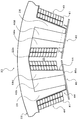
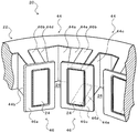
図1は、本発明の一実施例としての電動機用ステータ20の要部を示す平面図である。図2は、電動機用ステータ20の要部を示す外観図である。図2において、ステータコイル40は図示していない。図3は、図1のAA線での断面の概略を示す断面図である。図4は、ステータコア22に絶縁部材44を配置した様子を説明するための説明図である。図5は、絶縁部材44と固定部材46との配置および構成を説明するための説明図である。
FIG. 1 is a plan view showing a main part of an
電動機用ステータ20は、図示しないロータと共に、例えば電気自動車やハイブリッド自動車の走行用の駆動源あるいは発電機として用いられる三相交流電動機を構成するものである。電動機用ステータ20は、図1に示すように、ステータコア22と、ステータコイル40と、複数の絶縁部材44と、複数の固定部材46と、を備えている。
The
ステータコア22は、例えばプレス加工により円環状に形成された電磁鋼板を複数積層することにより構成されており、全体として円筒形状に形成されている。ステータコア22は、図1,図2に示すように、環状の外周部から周方向に間隔をおいて径方向内側に突出する複数のティース24と、それぞれ互いに隣り合うティース24の間の複数のスロット26と、を備えている。なお、ステータコア22は、例えば強磁性粉体を加圧成形すると共に焼結させることより一体に形成されてもよい。
The
ステータコイル40は、U相コイル、V相コイルおよびW相コイルを構成しており、図1に示すように、スロット26に挿入されている。ステータコイル40は、例えば長方形状(正方形状を含む)の断面を有する1本の平角線41をティース24の外周面に沿うように巻回軸に沿って複数段(例えば10段程度)だけ巻回すると共に、巻回軸の周りに複数回(本実施形態では、2回)若しくは1回だけ巻回することにより構成される。
The
複数の絶縁部材44は、例えば樹脂を射出成形することにより形成されている。絶縁部材44は、図1に示すように、スロット26内で、ステータコア22とステータコイル40との間に配置され、ステータコア22とステータコイル40とを絶縁している。絶縁部材44は、図1〜図5に示すように、ステータコア22の互いに隣り合うティース24の間に位置するステータコア22(ヨーク部)の内周面22a(図1参照)を覆う背部44aと、当該2つのティース24の対応する一方の側面を覆うようにステータコア22の周方向における背部44aの両端部から延出された側部44b,44cと、側部44b,44cのステータコア22の軸方向において同じ方向の端部から延出しティース24の軸方向の端面の少なくとも2分の1以上の面積を覆うフランジ部44d,44eと、を備える。絶縁部材44は、隣のスロット26内に配置された絶縁部材44と、フランジ部44d,44eが互い違いとなるように、隣のスロット26内に配置された絶縁部材44と図2,図4において上下逆さまに配置されている。したがって、ティース24の両端面には、隣り合うスロット26内に配置された絶縁部材44のフランジ部44dまたはフランジ部44eが配置されている。実施例では、1つのスロット26に1つの絶縁部材44を配置することによりステータコア22とステータコイル40と絶縁することができる。したがって、1つのティースの軸方向の両側から2つのコの字形の絶縁部材を向かい合わせて当該ティースに挿入するものと比べると、部品点数の増加を抑制することができる。
The plurality of insulating
複数の固定部材46は、対応するティース24に配置されており、図1〜図5に示すように、ティース24の内周面より外径が大きい基部46aと、基部46aの軸方向の端部の中央からステータコア22の径方向に延在する挟み込み部46b,46cと、を備える。基部46aは、ティース24の内周面より外径が大きいから、スロット26内に挿入されたステータコイル40が内径側へ飛び出すことを抑制することができる。挟み込み部46b,46cは、対となり、対応するティース24の両端面に配置されているフランジ部44d,44eを外側から挟み込む。こうした挟み込み部46b,46cにより、絶縁部材44をティース24に確実に固定することができる。
As shown in FIGS. 1 to 5, the plurality of fixing
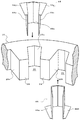
図6は、ステータコア22に複数の絶縁部材44を組み付けている様子を説明するための説明図である。ステータコア22に絶縁部材44を組み付ける際には、図示するように、各絶縁部材44を、隣のスロット26内に配置された絶縁部材44と、フランジ部44d,44eが互い違いとなるように、隣のスロット26に配置する絶縁部材44と図6において上下逆さまにした状態で、上下方向から各スロット26に挿入する。そして、絶縁部材44を各スロット26内に配置した後に、ティース24の内周側から各固定部材46を各ティース24に取り付け、ステータコイル40を絶縁部材44を介して各ティース24に巻回する。これにより、絶縁部材44によりステータコア22とステータコイル40とが絶縁される。
FIG. 6 is an explanatory diagram for explaining a state in which a plurality of insulating
ティース24の軸方向の両側から2つのコの字形の絶縁部材を向かい合わせてティース24に挿入するものでは、ステータコア22とステータコイル40との絶縁を確保するために、空隙ができないよう向かい合わた絶縁部材の端部同士を当接させる必要がある。端部を当接させると、端部に負荷が集中するから、強度を持たせるために、厚みを大きくする必要があり、ステータコイル40の占積率が低下してしまう。実施例の電動機用ステータ20では、1つのスロット26に1つの絶縁部材44を配置させればよいから、絶縁部材44の厚みを部分的に大きくする必要がない。したがって、ティース24の軸方向の両側から2つのコの字形の絶縁部材を向かい合わせてティース24に挿入するものと比較すると、ステータコイル40の占積率の低下を抑制することができる。
In the case where two U-shaped insulating members are inserted into the
また、実施例の電動機用ステータ20では、固定部材46に挟み込み部46b,46cを設けて、挟み込み部46b,46cでティース24の外側から絶縁部材44のフランジ部44e,44dを挟み込むことで絶縁部材44を固定する。これにより、スロット26に絶縁部材44を配置した後に絶縁部材44がずれることを抑制することができ、絶縁部材44をティース22に確実に固定することができる。
Further, in the
以上説明した実施例の電動機用ステータ20では、絶縁部材44は、互いに隣り合うティース24の間に位置するステータコア22の内周面22aを覆う背部44aと、背部44aの周方向における両端部から延出しティース24の対応する一方の側面を覆う側部44b,44cと、側部44b,44cのステータコア22の軸方向において同じ方向の両端部から延出しティース24の軸方向の少なくとも一部を覆うフランジ部44d,44eと、を有し、隣のスロット26に配置された絶縁部材44と、フランジ部44d,44eが互い違いとなるように配置されている。そして、固定部材46に、挟み込み部46b,46cを設け、挟み込み部46b,46cでティース24の両端面のフランジ部44d,44eを外側から挟み込むから、絶縁部材44をティース24により確実に固定することができる。
In the
実施例の電動機用ステータ20では、絶縁部材44のフランジ部44d,44eをティース24の軸方向の端面の少なくとも2分の1以上の面積を覆うものとしているが、フランジ部44d,44eがティース24の軸方向の端面を覆う面積を、端面の2分の1未満としてもよい。この場合、固定部材46の挟み込み部46b,46cを、基部46aの軸方向の端部の中央よりフランジ部44d,44e側にずれる位置に設けることが望ましい。
In the
実施例の主要な要素と課題を解決するための手段の欄に記載した発明の主要な要素との対応関係について説明する。実施例では、ステータコア22が「ステータコア」に相当し、絶縁部材44が「絶縁部材」に相当し、固定部材46が「固定部材」に相当する。
The correspondence between the main elements of the embodiment and the main elements of the invention described in the column of means for solving the problems will be described. In the embodiment, the
なお、実施例の主要な要素と課題を解決するための手段の欄に記載した発明の主要な要素との対応関係は、実施例が課題を解決するための手段の欄に記載した発明を実施するための形態を具体的に説明するための一例であることから、課題を解決するための手段の欄に記載した発明の要素を限定するものではない。即ち、課題を解決するための手段の欄に記載した発明についての解釈はその欄の記載に基づいて行なわれるべきものであり、実施例は課題を解決するための手段の欄に記載した発明の具体的な一例に過ぎないものである。 The correspondence between the main elements of the embodiment and the main elements of the invention described in the column of means for solving the problem is the same as that of the embodiment described in the column of means for solving the problem. Therefore, the elements of the invention described in the column of means for solving the problems are not limited. That is, the interpretation of the invention described in the column of means for solving the problems should be made based on the description of the column, and the examples are those of the invention described in the column of means for solving the problems. It is only a specific example.
以上、本発明を実施するための形態について実施例を用いて説明したが、本発明はこうした実施例に何等限定されるものではなく、本発明の要旨を逸脱しない範囲内において、種々なる形態で実施し得ることは勿論である。 As mentioned above, although the form for implementing this invention was demonstrated using the Example, this invention is not limited at all to such an Example, In the range which does not deviate from the summary of this invention, it is with various forms. Of course, it can be implemented.
本発明は、電動機用ステータの製造産業などに利用可能である。 The present invention can be used in the manufacturing industry of stators for electric motors.
20 電動機用ステータ、22 ステータコア、22a 内周面、24 ティース、26 スロット、40 ステータコイル、41 平角線、44 絶縁部材、44a 背部、44b,44c 側部、44d,44e フランジ部、46 固定部材、46a 基部、46b,46c 挟み込み部。 20 Stator for motor, 22 Stator core, 22a Inner peripheral surface, 24 teeth, 26 slots, 40 stator coil, 41 rectangular wire, 44 insulation member, 44a back, 44b, 44c side, 44d, 44e flange, 46 fixing member, 46a Base part, 46b, 46c Clamping part.
Claims (1)
前記スロット内に配置され、前記ステータコアと前記ステータコイルとを絶縁する複数の絶縁部材と、
を備える電動機用ステータであって、
対応する前記ティースに配置され、前記絶縁部材を前記ステータコアに固定する複数の固定部材、
を備え、
前記絶縁部材は、互いに隣り合う2つの前記ティースの間に位置する前記ステータコアの内周面を覆う背部と、前記背部の周方向における両端部から延出し前記2つの前記ティースの対応する一方の側面を覆う2つの側部と、2つの前記側部の前記ステータコアの軸方向において同じ方向の端部から延出し前記ティースの対応する前記軸方向の端面の少なくとも一部を覆う2つのフランジ部と、を有し、
前記絶縁部材は、隣の前記スロットに配置された前記絶縁部材と、前記フランジ部が互い違いとなるように配置されており、
前記固定部材は、対となり、対応する前記ティースの両端面に配置されている前記フランジ部を外側から挟み込む2つの挟み込み部、を有する、
電動機用ステータ。 A stator core having a plurality of teeth around which a stator coil is wound, and a plurality of slots between the plurality of teeth;
A plurality of insulating members disposed in the slot and insulating the stator core and the stator coil;
A stator for an electric motor comprising:
A plurality of fixing members disposed on the corresponding teeth and fixing the insulating member to the stator core;
With
The insulating member includes a back portion covering an inner peripheral surface of the stator core positioned between two adjacent teeth, and one side surface corresponding to the two teeth extending from both ends in the circumferential direction of the back portion. Two flanges that cover the at least part of the axial end surfaces corresponding to the teeth, extending from the ends in the same direction in the axial direction of the stator core of the two side portions, Have
The insulating member is arranged so that the insulating member arranged in the adjacent slot and the flange portion are staggered,
The fixing member includes a pair of two sandwiching portions that sandwich the flange portions disposed on both end surfaces of the corresponding teeth from outside.
Stator for electric motor.
Priority Applications (1)
| Application Number | Priority Date | Filing Date | Title |
|---|---|---|---|
| JP2016002179A JP2017123743A (en) | 2016-01-08 | 2016-01-08 | Stator for electric motor |
Applications Claiming Priority (1)
| Application Number | Priority Date | Filing Date | Title |
|---|---|---|---|
| JP2016002179A JP2017123743A (en) | 2016-01-08 | 2016-01-08 | Stator for electric motor |
Publications (1)
| Publication Number | Publication Date |
|---|---|
| JP2017123743A true JP2017123743A (en) | 2017-07-13 |
Family
ID=59306045
Family Applications (1)
| Application Number | Title | Priority Date | Filing Date |
|---|---|---|---|
| JP2016002179A Pending JP2017123743A (en) | 2016-01-08 | 2016-01-08 | Stator for electric motor |
Country Status (1)
| Country | Link |
|---|---|
| JP (1) | JP2017123743A (en) |
-
2016
- 2016-01-08 JP JP2016002179A patent/JP2017123743A/en active Pending
Similar Documents
| Publication | Publication Date | Title |
|---|---|---|
| US8610328B2 (en) | Rotary electric machine | |
| EP3476021B1 (en) | Stator and motor having the same | |
| US9923438B2 (en) | Method for manufacturing a rotary electric machine | |
| CN111095740B (en) | Insulator, stator including the same, and motor including the same | |
| WO2013042478A1 (en) | Rotary electrical machine and method for producing rotary electrical machine | |
| US20120161566A1 (en) | Stator for electric rotating machine and method of manufacturing the same | |
| CN206807168U (en) | The stator of motor | |
| US20070267932A1 (en) | Stator for inner rotor type rotating electric machine | |
| CN108736614A (en) | The stator of electric rotating machine | |
| JP2010063273A (en) | Stator | |
| JP6382080B2 (en) | Rotating electric machine stator and rotating electric machine equipped with the same | |
| US12021426B2 (en) | Stator with coil having first and second joint parts and core having fastening member | |
| JP6200854B2 (en) | Rotating electric machine stator | |
| JP2017079553A (en) | Stator for electric motor | |
| JP6279988B2 (en) | Electric motor stator | |
| JP5466117B2 (en) | Method for manufacturing stator of electric motor and method for positioning stator coil | |
| JP2017123743A (en) | Stator for electric motor | |
| JP2015136195A (en) | Stator of rotary electric machine | |
| JP2018125967A (en) | Rotary electric machine | |
| JP7463995B2 (en) | Armature and method for manufacturing the same | |
| WO2018020650A1 (en) | Stator and motor | |
| JP2017103986A (en) | Electric motor | |
| JP7790037B2 (en) | Motor | |
| US11750055B2 (en) | Terminal assembly of a driving motor | |
| JP2008271729A (en) | Electric motor |