JP2017078307A - Load bearing plate member - Google Patents
Load bearing plate member Download PDFInfo
- Publication number
- JP2017078307A JP2017078307A JP2015207144A JP2015207144A JP2017078307A JP 2017078307 A JP2017078307 A JP 2017078307A JP 2015207144 A JP2015207144 A JP 2015207144A JP 2015207144 A JP2015207144 A JP 2015207144A JP 2017078307 A JP2017078307 A JP 2017078307A
- Authority
- JP
- Japan
- Prior art keywords
- layer
- wood
- concrete
- laminated material
- fiber
- Prior art date
- Legal status (The legal status is an assumption and is not a legal conclusion. Google has not performed a legal analysis and makes no representation as to the accuracy of the status listed.)
- Granted
Links
Images


Abstract
Description
本発明は、耐力板部材に関する。 The present invention relates to a load bearing plate member.
ひき板を並べた層を、板の方向が層ごとに直交するように重ねて接着した大判のパネルである直交集成材(CLT、Cross Laminated Timber)が知られている。 There is known a cross laminated member (CLT), which is a large panel in which the layers in which the strips are arranged are stacked and bonded so that the directions of the plates are orthogonal to each other.
非特許文献1には、スギ材で構成された直交集成材(CLT)のせん断性能試験の報告書が開示されている。
Non-Patent
また、特許文献1には、木材層とコンクリート層又はモルタル層とを接着剤層によって結合する技術が開示されている。この先行技術では、水硬性のフレッシュコンクリート又はフレッシュモルタルが、未硬化の接着剤層上に注がれることで、コンクリート内に含まれる小石が接着剤層に潜入し、これにより両層の硬化後にせん断力を伝達する噛合を形成している。
非特許文献1には、直交集成材(CLT)をスラブに使用する例が開示されている。しかし、直交集成材で構成されたスラブの場合、コンクリート造のスラブと比較し、強度が低い、防音性能が低い、耐火性能が低いなど、使用に関する制約が多い。
Non-Patent
これに対して、特許文献1に記載の技術のように、木材層とコンクリート層又はモルタル層とを接着剤層によって結合したスラブとすることで、強度が向上し、また防音性能や耐火性能も向上する。
On the other hand, as in the technique described in
しかし、この技術の木材層は、木質繊維が一方向であり、仮にこの木質繊維を、鉄筋コンクリート造における主筋に相当するとした場合、力を分散させる配力筋に相当する木質繊維を有していないので、木質層に大きな耐力を確保させることは困難である。このため耐力板部材の耐力を向上させるためにはコンクリート層又はモルタル層の層厚を厚くする必要があるが、層厚を厚くすると重量が増加する。よって、この点において改善の余地があった。 However, the wood layer of this technique has one-way wood fiber, and if this wood fiber is equivalent to the main reinforcement in reinforced concrete construction, it does not have wood fiber equivalent to the distribution bars that distribute the force. Therefore, it is difficult to ensure a large yield strength in the wood layer. For this reason, in order to improve the proof stress of a strength plate member, it is necessary to increase the layer thickness of a concrete layer or a mortar layer, but when the layer thickness is increased, the weight increases. Therefore, there was room for improvement in this respect.
本発明は、上記事実を鑑み、耐力板部材を軽量化しつつ、耐力板部材の耐力を向上させることが目的である。 In view of the above facts, an object of the present invention is to improve the proof stress of a load bearing plate member while reducing the weight of the load bearing plate member.
請求項1の耐力板部材は、木質繊維の繊維方向が層毎に交差するように積層された木質層と、前記木質層の一方の面に接合されたコンクリート層又はモルタル層と、を備えている。
The load-bearing plate member according to
請求項1に記載の発明では、木質層とコンクリート層又はモルタル層とを接合した構造とすることで、コンクリート層又はモルタル層のみで構成された場合よりも、軽量化される。
In invention of
また、木質層の木質繊維の繊維方向が層毎に交差しているので、応力を分散することができる。 Moreover, since the fiber directions of the wood fibers of the wood layer intersect each layer, the stress can be dispersed.
ここで、木質層の機能を鉄筋コンクリートスラブに例えて説明すると、一方の繊維方向の木質繊維が主筋に相当する機能を果す一方、これに交差する他方の繊維方向の木質繊維が配力筋に相当する機能を果すので、応力を分散することができる。 Here, the function of the wood layer will be described as a reinforced concrete slab. The wood fiber in one fiber direction functions as the main reinforcement, while the wood fiber in the other fiber direction intersecting this corresponds to the distribution bar. Since the function is performed, the stress can be dispersed.
よって、木質繊維が一方向の場合と比較し、木質層の耐力が向上するので、その分、コンクリート層又はモルタル層の厚みを薄くすることができる。つまり、木質繊維が一方向の場合と比較し、耐力板部材を軽量化しつつ、耐力板部材の耐力が向上する。 Therefore, compared with the case where the wood fiber is unidirectional, the yield strength of the wood layer is improved, and accordingly, the thickness of the concrete layer or the mortar layer can be reduced. That is, the strength of the load bearing plate member is improved while reducing the weight of the load bearing plate member as compared with the case where the wood fiber is unidirectional.
請求項2の耐力板部材は、前記木質層と前記コンクリート層又は前記モルタル層との間で応力を伝達する応力伝達手段を有している。
The load-bearing plate member according to
請求項2に記載の発明では、面外曲げ変形等によって木質層とコンクリート層又はモルタル層との間に作用するせん断力が、応力伝達手段によって効果的に伝達される。したがって、耐力板部材の耐力が更に向上する。
In the invention described in
請求項3の耐力板部材は、前記木質層は梁に掛け渡されると共に、前記木質層の上面に前記コンクリート層又は前記モルタル層が接合され、前記木質層の最下層の木質繊維の繊維方向が、前記木質層の掛け渡し方向に沿っている。 The load-bearing plate member according to claim 3, wherein the wood layer is stretched over a beam, the concrete layer or the mortar layer is joined to an upper surface of the wood layer, and the fiber direction of the wood fiber in the lowest layer of the wood layer is , Along the spanning direction of the wood layer.
請求項3に記載の発明では、木質層の最下層の木質繊維の繊維方向が木質層の掛け渡し方向に沿っていることで、木質繊維が曲げ変形時の引張力に効果的に効く。したがって、耐力板部材の耐力が更に向上する。 In the invention according to claim 3, the fiber direction of the wood fiber in the lowermost layer of the wood layer is along the extending direction of the wood layer, so that the wood fiber is effective in the tensile force at the time of bending deformation. Therefore, the proof stress of the load bearing plate member is further improved.
本発明によれば、耐力板部材を軽量化しつつ、耐力板部材の耐力を向上させることができる。 According to the present invention, it is possible to improve the proof stress of the load bearing plate member while reducing the weight of the load bearing plate member.
図1〜図6を用いて、本発明の一実施形態に係る耐力板部材を用いたスラブについて説明する。なお、各図中の矢印Zは鉛直方向を示し、矢印Yは、後述する木質層(直交集成材)の掛け渡し方向を示し、矢印XはY方向及びZ方向と直交する方向を示している。 A slab using a load bearing plate member according to an embodiment of the present invention will be described with reference to FIGS. In addition, the arrow Z in each figure shows a perpendicular direction, the arrow Y shows the crossing direction of the wooden layer (orthogonal laminated material) mentioned later, and the arrow X shows the direction orthogonal to the Y direction and the Z direction. .
<構造>
先ず、本発明の一実施形態に係る耐力板部材を用いたスラブの構造について説明する。
<Structure>
First, a structure of a slab using a load bearing plate member according to an embodiment of the present invention will be described.
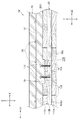
図2に示すように、スラブ10は、複数の直交集成材(CLT、Cross Laminated Timber)100で構成された木質層20と、この木質層20の上面20Uに接合されたコンクリート層30と、を含んで構成されている。
As shown in FIG. 2, the
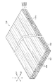
図1及び図2に示すように、木質層20(図2参照)を構成する直交集成材100は、ラミナ(ひき板)102を並べた層110A、110B、110Cを、ラミナ102の木質繊維104の繊維方向S1(図1参照)及び繊維方向S2が層110A、110B、110Cごとに直交するように重ねて接着したパネル材である。
As shown in FIG. 1 and FIG. 2, the orthogonal laminated
本実施形態の直交集成材100は、層110A、110B、110Cの三層構造とされ、厚み方向の両外側の層110A及び層110Cの木質繊維104の繊維方向S1(図1参照)が長辺方向(図1参照)に沿っており、中間の層110Bの木質繊維104の繊維方向S2が短辺方向(図1参照)に沿っている。また、矢印Tは直交集成材の板厚方向(面外方向)を示している。なお、図1及び図2以外の図では、図が煩雑になって見難くなるのを避けるため、木質繊維104の図示を省略している。
The orthogonal laminated
図3(A)に示すように、平面視において、X方向及びY方向に沿って格子状に配置された梁12及び梁14がスラブ10(図2参照)を支持している。木質層20を構成する直交集成材100は、長辺方向をY方向に沿って配置されおり、X方向に沿って配置された梁14に掛け渡されている。よって、直交集成材100の掛け渡し方向はY方向である。そして、直交集成材100の最下層である層110A(図2参照)の木質繊維104(図1及び図2参照)の繊維方向S1が、この掛け渡し方向であるY方向に沿うように配置されている。
As shown in FIG. 3A, the
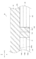
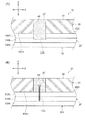
図3及び図4に示すように、直交集成材100の各辺部の端面120には、面内方向に凹んだ平面視半円形状の凹部122が形成されている。図3に示すように、梁12及び梁14に載っている直交集成材100の端面120は間隔をあけて配置されている(図4も参照)。これに対して、梁12及び梁14に載っていない直交集成材100の他の端面120同士は接触又は近接して配置されている。図3では端面120同士が接触して図示されているが、実際には、図6に示すように、接触施工上、誤差を吸収するために、直交集成材100の端面120同士は、若干(約10mm程度)の隙間をあけて配置されている。なお、直交集成材100の端面120同士は接触していてもよいし、10mm以上の隙間があいていてもよい。
As shown in FIGS. 3 and 4, the
また、図2及び図3に示すように、直交集成材100の上面100U(木質層20の上面20U)には、面外方向に凹んだ複数の凹部130が形成されている。本実施形態では、これら凹部130は、直交集成材100を製造したのちに、上面100Uを削って形成している。しかし、他の方法で凹部130を形成してもよい。例えば、ラミナ102(図1及び図2参照)を接着接合する際に、凸部を設けたプレスで圧締することで、直交集成材100の上面100Uに凹部130を形成してもよい。
As shown in FIGS. 2 and 3, a plurality of
なお、本実施形態では、図2に示すように、凹部130には、ラグスクリュー132がねじ込まれている。
In this embodiment, as shown in FIG. 2, a
図2及び図5に示すように、直交集成材100で構成された木質層20の上面20Uにコンクリートが打設され、コンクリート層30が形成されている。なお、コンクリートを打設する際に、直交集成材100(木質層20)が型枠として機能する。また、コンクリート層30のみでスラブ10の短期耐力が確保されるように設計されている。
As shown in FIGS. 2 and 5, concrete is cast on the
図2に示すように、直交集成材100の上面100U(木質層20の上面20U)の各凹部130(図3も参照)にコンクリートが流れ込み、コンクリート層30の下面に下方に向けて突出し、凹部130に係合するコッター36(応力伝達手段の一例)が形成される。また、前述したラグスクリュー132(応力伝達手段の一例)がコンクリート層30に埋設される。
As shown in FIG. 2, the concrete flows into each recess 130 (see also FIG. 3) of the
図6に示すように、直交集成材100の各辺部の端面120の凹部122間にもコンクリートが流れ込み、コンクリート層30の下面に下方に向けて突出し、凹部122に係合する凸部33が形成される。なお、図6では、梁12及び梁14に載っていない直交集成材100の端面120を図示しているが、梁12及び梁14に載っている直交集成材100の端面120も同様である(図5参照)。また、コンクリートを打設する際には、梁12及び梁14に載っていない直交集成材100の端面120の下面には、図示していない添木などを当ててコンクリートが落下しないようにしている。
As shown in FIG. 6, the concrete also flows between the
本実施形態では、直交集成材100の上面100U(板面)は、無垢材等に比べ、吸水性が低いので、コンクリートを打設する際に、上面20Uに防止処理、例えば防水シートを敷いたり防水塗料を塗布したりすることは行っていない。
In the present embodiment, the
なお、本実施形態のスラブ10は、図3に示す水周りとなる領域18には、コンクリート層30を設けないで(コンクリートを打設しないで)段差を設けている。よって、この領域18の上面20Uには、防水シートや防水塗装などの防水処理を行っている。
In the
図2に示すように、コンクリート層30には、Y方向に沿って配筋された主筋34と、X方向に沿って配筋された配力筋32と、が埋設されている。なお、主筋34が上側に配置されている。なお、図2以外の図(後述する変形例の図を含む)では、主筋34及び図32の図示を省略している。
As shown in FIG. 2, the
図5に示すように、本実施形態の梁12は、鉄筋コンクリート造とされ、梁方向(Y方向)に沿って配筋された梁主筋44と、梁主筋44の周りに設けられたせん断補強筋42とが埋設されている。また、L字形状の鉄筋で構成された補強筋46が、梁12から直交集成材100の端面120と端面120との隙間124を通り、コンクリート層30に延在している。
As shown in FIG. 5, the
なお、図示は省略するが、本実施形態の梁14も同様に鉄筋コンクリート造とされ、梁方向(X方向)に沿って配筋された梁主筋44と、梁主筋44の周りに設けられたせん断補強筋42とが埋設されている。また、同様に、L字形状の補強筋46が、梁14から直交集成材100の端面120と端面120との隙間124を通り、コンクリート層30に延在するように埋設されている。
Although illustration is omitted, the
<作用及び効果>
次に、本実施形態の作用及び効果について説明する。
<Action and effect>
Next, the operation and effect of this embodiment will be described.
本実施形態のスラブ10は、木質層20とコンクリート層30とを接合した構造であるので、コンクリート層のみで構成されたスラブよりも軽量化されると共に、木質層のみで構成されたスラブよりも耐火性能及び防音性能が向上する。なお、本実施形態のスラブ10は、コンクリート層30のみで短期耐力が確保されるように設計されている。よって、仮に火災時に木質層20が焼失しても必要な耐力が確保される。
Since the
また、木質層20は、木質繊維104の繊維方向が層110A、110B、110C毎に直交する直交集成材100を用いているので、応力を分散することができる。
Moreover, since the
ここで、木質層20の機能を鉄筋コンクリートスラブに例えて説明すると、一方の繊維方向S1の木質繊維104が主筋に相当する機能を果す一方、これに直交する他方の繊維方向S2の木質繊維104が配力筋に相当する機能を果すので、応力を分散することができる。
Here, when the function of the
よって、木質層20の耐力が向上するので、その分、コンクリート層30の厚みを薄くすることができる。つまり、木質層20の木質繊維104の方向が一方向である場合と比較し、スラブ10を軽量化しつつ、スラブ10の耐力が向上する。
Therefore, since the yield strength of the
また、木質層20(直交集成材100)の最下層である層110Aの木質繊維104の繊維方向S1が、木質層20の掛け渡し方向であるY方向に沿っているので、木質繊維104が曲げ変形時の引張力に効果的に効く。更に、木質層20の掛け渡し方向であるY方向に沿って配筋された主筋34は、コンクリート層30の上側に配置されているので、木質繊維104と同様に引張力に効果的に効く。したがって、スラブ10の耐力が更に向上する。
Further, since the fiber direction S1 of the
また、面外曲げ変形や地震等によって木質層20とコンクリート層30との間に作用するせん断力が、コンクリート層30のコッター36が木質層20(直交集成材100)の凹部130に係合することで、効果的に伝達される。更に、本実施形態では、木質層20の凹部130にねじ込まれ、コンクリート層30に埋設されラグスクリュー132によっても木質層20とコンクリート層30との間に作用するせん断力が効果的に伝達される。したがって、スラブ10の耐力が更に向上する。
Further, the shear force acting between the
なお、本実施形態では、コッター36とラグスクリュー132とは同じ場所に設けたが、異なる場所にそれぞれを設けてもよい。また、本実施形態では、コッター36とラグスクリュー132との二つでせん断力を伝達したが、コッター36及びラグスクリュー132のいずれか一方のみが設けられていてもよい。
In the present embodiment, the
また、直交集成材100(木質層20)の上面100Uを目粗して凹凸を形成することで、木質層20とコンクリート層30との間に作用するせん断力を伝達してもよい。
Moreover, you may transmit the shear force which acts between the
また、木質層20を構成する直交集成材100の端面120の凹部122にコンクリート層30の凸部33が係合しているので、直交集成材100の端面120間に作用するせん断力が効果的に伝達される。
Moreover, since the
また、梁12、14から直交集成材100の端面120と端面120との隙間124を通り、コンクリート層30に延在するL字形状の補強筋46によって、梁12,14とスラブ10とが接合され一体化されている。
Further, the
なお、L字形状の鉄筋で構成された補強筋46以外の応力伝達部材が梁12、14に設けられると共に、直交集成材100の端面120と端面120との隙間124を通り、コンクリート層30に延在することで、梁12,14とスラブ10とが接合され一体化されてもよい。補強筋46以外の応力伝達部材としては、頭付スタッド、ナット付鉄筋及びラグスクリューなどが挙げられる。
In addition, stress transmission members other than the reinforcing
また、コンクリートを打設する際に、直交集成材100(木質層20)が型枠として機能するので、別部材としての型枠が不要又は削減されると共に、型枠の廃棄が不要又は削減される。 In addition, when the concrete is placed, since the orthogonal laminated material 100 (the wood layer 20) functions as a formwork, the formwork as a separate member is unnecessary or reduced, and the disposal of the formwork is unnecessary or reduced. The
また、木質層20のみで構成されたスラブよりも、強度が高いので梁14間のスパンを広くできる。
Moreover, since the strength is higher than that of the slab composed only of the
また、コンクリート層30のみで構成されたスラブでは、木質の意匠とするためには別途木質の天井板を設ける必要があるが、本実施形態のスラブ10では木質の天井板を設けることなく、木質の意匠を得ることができる。
In addition, in the slab composed only of the
<変形例>
次に、本実施形態の変形例について説明する。
<Modification>
Next, a modification of this embodiment will be described.
(第一変形例及び第二変形例)
上記実施形態では、木質層20を構成する直交集成材100の端面120に凹部122を形成し、この凹部122にコンクリート層30の凸部33が係合することで、直交集成材100の端面120間に作用するせん断力を伝達していた。しかし、この構造以外で、直交集成材100の端面120間に作用するせん断力を伝達してもよい。そして、この構造以外のせん断力の伝達方法の例を第一変形例及び第二変形例として説明する。
(First modification and second modification)
In the said embodiment, the recessed
図7に示す第一変形例では、直交集成材100の端面120には、水平方向にラグスクリュー132がねじ込まれている。ラグスクリュー132は、直交集成材100の端面120間に形成されたコンクリート層30の下側に突出するリブ状の凸部37に埋設されている。
In the first modification shown in FIG. 7, a
そして、直交集成材100の端面120間に作用するせん断力が、ラグスクリュー132及びコンクリート層30の凸部37を介して伝達される。
And the shear force which acts between the end surfaces 120 of the orthogonal
なお、図8(A)のように直交集成材100の端面120に階段状の凹部125を形成して、ここにラグスクリュー132が埋設されるコンクリート層30の凸部37を設けるようにしてもよい。
As shown in FIG. 8A, a stepped
或いは、図8(B)のように直交集成材100の端面120に傾斜面を形成することによって凹部126を形成して、ここにラグスクリュー132が埋設されるコンクリート層30の逆三角形状の凸部37を設けるようにしてもよい。
Alternatively, as shown in FIG. 8 (B), a
図9に示す第二変形例では、直交集成材100の上面100Uの凹部131から直交集成材100に接合筋134が差し込まれている。この接合筋134は、凹部131に係合する凸部39とコンクリート層30とに跨るように埋設されている。
In the second modification shown in FIG. 9, a joining
そして、直交集成材100の端面120間に作用するせん断力が、接合筋134及びコンクリート層30を介して伝達される。
And the shear force which acts between the end surfaces 120 of the orthogonal
(第三変形例)
上記実施形態の梁12、14は、鉄筋コンクリート造であったが、これに限定されない。例えば、鉄骨鉄筋コンクリート造、木質造及び鉄骨造であってもよい。鉄骨鉄筋コンクリート造、木質造及び鉄骨造の梁と、スラブ10とは、適宜適当な技術を用いて接合すればよい。よって、鉄骨梁15とスラブ10との接合の例を第三変形例として説明する。
(Third modification)
Although the
図10に示す第三変形例では、H形鋼で構成された鉄骨梁15の上に、木質層20を構成する直交集成材100が掛け渡されている。この木質層20の上にコンクリートを打設してコンクリート層30が設けられている。
In the third modification shown in FIG. 10, the orthogonal
鉄骨梁15の上側のフランジ15Aには、スタッド48が接合されている。このスタッド48は、直交集成材100の端面120間の隙間124を通ってコンクリート層30まで延出している。そして、このスタッド48によって鉄骨梁15とスラブ10とが接合され一体化されている。
A
(第四変形例及び第五変形例)
上記実施形態では、木質層20の上面20U(直交集成材100の上面100U)にコンクリートを打設してコンクリート層30を設けていたが、これに限定されない。よって、工場等であらかじめ製造されたプレキャストコンクリートでコンクリート層30を構成する例を第四変形例及び第五変形例として説明する。
(Fourth Modification and Fifth Modification)
In the above embodiment, the
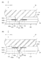
図11(A)に示す第四変形では、平面視で円形の貫通孔47が形成された複数のプレキャスト板35でコンクリート層30が構成されている。なお、プレキャスト板35には予め主筋及び配力筋が埋設されている。木質層20(直交集成材100)の上面100Uには、貫通孔47に対応する位置に、平面視で円形の凹部133が形成されている。
In the fourth modification shown in FIG. 11A, the
木質層20(直交集成材100)の上面100Uにプレキャスト板35を設置したのち、貫通孔47に充填材(コンクリート及びモルタルなど)を充填することで、貫通孔47及び凹部133に係合する円柱状の係合部49が形成される。
After the
そして、この貫通孔47及び凹部133に係合する係合部49(応力伝達手段の一例)によって、木質層20とコンクリート層30との間に作用するせん断力が伝達される。
And the shearing force which acts between the
図11(B)に示す第五変形例では、複数のプレキャスト板35でコンクリート層30が構成されている。木質層20の上面20U(直交集成材100の上面100U)には、貫通孔47に対応する位置に、ラグスクリュー132が設けられている。
In the fifth modification shown in FIG. 11 (B), the
木質層20(直交集成材100)の上面100Uにプレキャスト板35を設置したのち、貫通孔47に充填材(コンクリート及びモルタルなど)を充填することで、貫通孔47に係合し、ラグスクリュー132が埋設された円柱状の係合部51が形成される。
After the
そして、貫通孔47に係合しラグスクリュー132が埋設された係合部51(応力伝達手段の一例)によって、木質層20とコンクリート層30との間に作用するせん断力が伝達される。
And the shearing force which acts between the
なお、図11(A)の第四変形例の木質層20の凹部133にラグスクリュー132を設けてもよい。
In addition, you may provide the
また、プレキャスト板35と木質層20(直交集成材100)との間に接着剤層(応力伝達手段の一例)を設けて、プレキャスト板35と木質層20とを接着接合してもよい。
Further, an adhesive layer (an example of stress transmission means) may be provided between the
<その他>
尚、本発明は上記実施形態に限定されない。
<Others>
The present invention is not limited to the above embodiment.
例えば、木質層20(図2参照)を構成する直交集成材100は、層110A、110B、110Cの三層構造であったが、これに限定されない。直交集成材100は、二層構造であってもよし、四層以上の層で構成されていてもよい。
For example, although the orthogonal
また、例えば、木質層20は、直交集成材(CLT(Cross Laminated Timber))100で構成されていたが、これに限定されない。単板の繊維方向を揃えて積層し接着した単板積層材(LVL(Laminated Veneer Lumber))の繊維方向を交差するように重ねて用いてもよい。要は、木質繊維の繊維方向が層毎に交差するように積層された木質層20であればよい。
Further, for example, the
また、コンクリート層30には、Y方向に沿って配筋された主筋34と、X方向に沿って配筋された配力筋32と、が埋設されているが、これに限定されない。コンクリート層30には面外方向に見た場合に複数の鉄筋が交差するように配筋されていればよい。また、最上部に配筋された鉄筋の配筋方向が、木質層20の掛け渡し方向に沿っていることが望ましい。
Moreover, although the
また、上記実施形態では、木質層20の上にはコンクリート層30を設けたが、モルタルで構成されたモルタル層を木質層20の上に設けてもよい。
Moreover, in the said embodiment, although the
また、上記実施形態では、本発明の耐力板部材を用いたスラブ10について説明したが、これに限定されない。本発明の耐力板部材は、壁にも用いることができる。なお、壁に用いる場合は、木質層の最外側の層の木質繊維の繊維方向が、上下方向に沿っていることが望ましい。また、壁に用いる場合は、コンクリート層30の最外側に上下方向に沿っている主筋を配置することが望ましい。
Moreover, although the said embodiment demonstrated the
なお、木質層の最下層の木質繊維の繊維方向が木質層の掛け渡し方向に沿っていなくてもよいし、木質層の最外側の木質繊維の繊維方向が上下方向に沿っていいなくてもよい。また、コンクリート層30又はモルタル層に配筋する主筋34及び配力筋32の配置も任意である。
The fiber direction of the wood fiber in the lowermost layer of the wood layer may not be along the spanning direction of the wood layer, or the fiber direction of the wood fiber at the outermost side of the wood layer may not be along the vertical direction. Good. Moreover, the arrangement | positioning of the
また、上記実施形態及び各変形例は、適宜、組み合わされて実施可能である。 Moreover, the said embodiment and each modification can be implemented in combination as appropriate.
更に、本発明の要旨を逸脱しない範囲において種々なる態様で実施し得ることは言うまでもない Furthermore, it cannot be overemphasized that it can implement with a various aspect in the range which does not deviate from the summary of this invention.
10 スラブ
14 梁
20 木質層
30 コンクリート
36 コッター(応力伝達手段の一例)
49 係合部(応力伝達手段の一例)
51 係合部(応力伝達手段の一例)
104 木質繊維
132 ラグスクリュー(応力伝達手段の一例)
10
49 engagement part (an example of stress transmission means)
51 engaging portion (an example of stress transmission means)
104
Claims (3)
前記木質層の一方の面に接合されたコンクリート層又はモルタル層と、
を備える耐力板部材。 A wooden layer laminated so that the fiber directions of the wooden fibers intersect each layer;
A concrete layer or a mortar layer joined to one side of the wood layer;
A load bearing plate member.
請求項1に記載の耐力板部材。 Having stress transmission means for transmitting stress between the wood layer and the concrete layer or the mortar layer;
The load bearing plate member according to claim 1.
前記木質層の最下層の木質繊維の繊維方向が、前記木質層の掛け渡し方向に沿っている、
請求項1又は請求項2に記載の耐力板部材。 The wood layer is stretched over the beam, and the concrete layer or the mortar layer is joined to the top surface of the wood layer,
The fiber direction of the wood fiber in the lowest layer of the wood layer is along the spanning direction of the wood layer,
The load bearing plate member according to claim 1 or 2.
Priority Applications (1)
| Application Number | Priority Date | Filing Date | Title |
|---|---|---|---|
| JP2015207144A JP6754560B2 (en) | 2015-10-21 | 2015-10-21 | Bearing plate member |
Applications Claiming Priority (1)
| Application Number | Priority Date | Filing Date | Title |
|---|---|---|---|
| JP2015207144A JP6754560B2 (en) | 2015-10-21 | 2015-10-21 | Bearing plate member |
Publications (2)
| Publication Number | Publication Date |
|---|---|
| JP2017078307A true JP2017078307A (en) | 2017-04-27 |
| JP6754560B2 JP6754560B2 (en) | 2020-09-16 |
Family
ID=58665340
Family Applications (1)
| Application Number | Title | Priority Date | Filing Date |
|---|---|---|---|
| JP2015207144A Active JP6754560B2 (en) | 2015-10-21 | 2015-10-21 | Bearing plate member |
Country Status (1)
| Country | Link |
|---|---|
| JP (1) | JP6754560B2 (en) |
Cited By (21)
| Publication number | Priority date | Publication date | Assignee | Title |
|---|---|---|---|---|
| JP2018193820A (en) * | 2017-05-19 | 2018-12-06 | 株式会社竹中工務店 | Slab structure |
| JP2019015053A (en) * | 2017-07-05 | 2019-01-31 | 株式会社竹中工務店 | Junction structure of wooden floor slab |
| JP2019027021A (en) * | 2017-07-25 | 2019-02-21 | 株式会社竹中工務店 | Laminated floor slab |
| JP2019031778A (en) * | 2017-08-04 | 2019-02-28 | 株式会社竹中工務店 | Junction structure of wooden floor slab |
| JP2019031777A (en) * | 2017-08-04 | 2019-02-28 | 株式会社竹中工務店 | Joint structure of woody slab |
| JP2019031787A (en) * | 2017-08-04 | 2019-02-28 | 株式会社竹中工務店 | Junction structure |
| JP2019039177A (en) * | 2017-08-23 | 2019-03-14 | 株式会社竹中工務店 | Junction structure |
| JP2019039171A (en) * | 2017-08-23 | 2019-03-14 | 株式会社竹中工務店 | Composite slab |
| JP2019070291A (en) * | 2017-10-11 | 2019-05-09 | 株式会社竹中工務店 | Two-layer structure roof and repair method of existing structure |
| JP2019100057A (en) * | 2017-11-30 | 2019-06-24 | 大成建設株式会社 | Construction method of wooded/rc mixed structure building and wooden/rc mixed structure building |
| JP2019105146A (en) * | 2017-12-11 | 2019-06-27 | 株式会社ライト建築事務所 | Connected body of lego-type composite structure formed by crimping and joining common members of clt slab and pc beam and having fire resistance |
| JP2020026660A (en) * | 2018-08-10 | 2020-02-20 | 株式会社熊谷組 | Floor structure |
| JP2020045683A (en) * | 2018-09-19 | 2020-03-26 | 株式会社竹中工務店 | Floor slab/ceiling slab connection structure and woody slab unit |
| JP2020105694A (en) * | 2018-12-26 | 2020-07-09 | 三菱地所株式会社 | Floor clt construction method and floor clt structure |
| JP2020105700A (en) * | 2018-12-26 | 2020-07-09 | 三菱地所株式会社 | Orthogonal laminated plate |
| JP2020105697A (en) * | 2018-12-26 | 2020-07-09 | 株式会社竹中工務店 | Floor structure |
| JP2020190126A (en) * | 2019-05-22 | 2020-11-26 | 三菱地所株式会社 | Lumber form with reinforcement and construction method using lumber form with reinforcement |
| JP2020197054A (en) * | 2019-06-03 | 2020-12-10 | 株式会社竹中工務店 | Composite slab structure and construction method of composite slab |
| JP2022515231A (en) * | 2018-12-19 | 2022-02-17 | マイテック・ホールディングズ・インコーポレイテッド | Anchors for concrete floors |
| JP2022059666A (en) * | 2020-10-02 | 2022-04-14 | 大成建設株式会社 | Earthquake reinforcement structure of existing building using clt |
| KR20220074078A (en) * | 2020-11-27 | 2022-06-03 | 서울대학교산학협력단 | Eco hybrid timber slab |
Citations (6)
| Publication number | Priority date | Publication date | Assignee | Title |
|---|---|---|---|---|
| JPS5647016U (en) * | 1979-09-17 | 1981-04-27 | ||
| JPS6131810U (en) * | 1984-07-31 | 1986-02-26 | 豊田通商株式会社 | plywood |
| JP2000142571A (en) * | 1998-11-05 | 2000-05-23 | Life Stage Kigyo Kumiai | Composite sliding material |
| JP2010047910A (en) * | 2008-08-19 | 2010-03-04 | Takenaka Komuten Co Ltd | Composite beam, construction method for the same, and fireproof building |
| JP2013083104A (en) * | 2011-10-11 | 2013-05-09 | Takenaka Komuten Co Ltd | Composite floor structure, fire resistant structure and construction method of composite floor structure |
| JP2015151841A (en) * | 2014-02-19 | 2015-08-24 | Jfe建材株式会社 | Composite floor structure |
-
2015
- 2015-10-21 JP JP2015207144A patent/JP6754560B2/en active Active
Patent Citations (6)
| Publication number | Priority date | Publication date | Assignee | Title |
|---|---|---|---|---|
| JPS5647016U (en) * | 1979-09-17 | 1981-04-27 | ||
| JPS6131810U (en) * | 1984-07-31 | 1986-02-26 | 豊田通商株式会社 | plywood |
| JP2000142571A (en) * | 1998-11-05 | 2000-05-23 | Life Stage Kigyo Kumiai | Composite sliding material |
| JP2010047910A (en) * | 2008-08-19 | 2010-03-04 | Takenaka Komuten Co Ltd | Composite beam, construction method for the same, and fireproof building |
| JP2013083104A (en) * | 2011-10-11 | 2013-05-09 | Takenaka Komuten Co Ltd | Composite floor structure, fire resistant structure and construction method of composite floor structure |
| JP2015151841A (en) * | 2014-02-19 | 2015-08-24 | Jfe建材株式会社 | Composite floor structure |
Cited By (35)
| Publication number | Priority date | Publication date | Assignee | Title |
|---|---|---|---|---|
| JP2018193820A (en) * | 2017-05-19 | 2018-12-06 | 株式会社竹中工務店 | Slab structure |
| JP2019015053A (en) * | 2017-07-05 | 2019-01-31 | 株式会社竹中工務店 | Junction structure of wooden floor slab |
| JP2019027021A (en) * | 2017-07-25 | 2019-02-21 | 株式会社竹中工務店 | Laminated floor slab |
| JP7099668B2 (en) | 2017-07-25 | 2022-07-12 | 株式会社竹中工務店 | Jump-out structure of laminated floor slab |
| JP2019031778A (en) * | 2017-08-04 | 2019-02-28 | 株式会社竹中工務店 | Junction structure of wooden floor slab |
| JP2019031777A (en) * | 2017-08-04 | 2019-02-28 | 株式会社竹中工務店 | Joint structure of woody slab |
| JP2019031787A (en) * | 2017-08-04 | 2019-02-28 | 株式会社竹中工務店 | Junction structure |
| JP7003378B2 (en) | 2017-08-04 | 2022-02-10 | 株式会社竹中工務店 | Joined structure |
| JP7000654B2 (en) | 2017-08-04 | 2022-02-10 | 株式会社竹中工務店 | Joined structure of wood deck |
| JP2019039177A (en) * | 2017-08-23 | 2019-03-14 | 株式会社竹中工務店 | Junction structure |
| JP2019039171A (en) * | 2017-08-23 | 2019-03-14 | 株式会社竹中工務店 | Composite slab |
| JP7003379B2 (en) | 2017-08-23 | 2022-02-10 | 株式会社竹中工務店 | Joined structure |
| JP7234488B2 (en) | 2017-10-11 | 2023-03-08 | 株式会社竹中工務店 | Two-layer structure roof and method for repairing existing structure |
| JP2019070291A (en) * | 2017-10-11 | 2019-05-09 | 株式会社竹中工務店 | Two-layer structure roof and repair method of existing structure |
| JP2019100057A (en) * | 2017-11-30 | 2019-06-24 | 大成建設株式会社 | Construction method of wooded/rc mixed structure building and wooden/rc mixed structure building |
| JP2019105146A (en) * | 2017-12-11 | 2019-06-27 | 株式会社ライト建築事務所 | Connected body of lego-type composite structure formed by crimping and joining common members of clt slab and pc beam and having fire resistance |
| JP2020026660A (en) * | 2018-08-10 | 2020-02-20 | 株式会社熊谷組 | Floor structure |
| JP2020045683A (en) * | 2018-09-19 | 2020-03-26 | 株式会社竹中工務店 | Floor slab/ceiling slab connection structure and woody slab unit |
| JP7131232B2 (en) | 2018-09-19 | 2022-09-06 | 株式会社竹中工務店 | Joint structure of floor slab and ceiling slab and wood block unit |
| JP2022515231A (en) * | 2018-12-19 | 2022-02-17 | マイテック・ホールディングズ・インコーポレイテッド | Anchors for concrete floors |
| JP2020105694A (en) * | 2018-12-26 | 2020-07-09 | 三菱地所株式会社 | Floor clt construction method and floor clt structure |
| JP2020105700A (en) * | 2018-12-26 | 2020-07-09 | 三菱地所株式会社 | Orthogonal laminated plate |
| JP2020105697A (en) * | 2018-12-26 | 2020-07-09 | 株式会社竹中工務店 | Floor structure |
| JP7364746B2 (en) | 2018-12-26 | 2023-10-18 | 三菱地所株式会社 | orthogonal laminated board |
| JP2022130545A (en) * | 2018-12-26 | 2022-09-06 | 三菱地所株式会社 | Orthogonal laminated plate |
| JP2020190126A (en) * | 2019-05-22 | 2020-11-26 | 三菱地所株式会社 | Lumber form with reinforcement and construction method using lumber form with reinforcement |
| CN113853465A (en) * | 2019-05-22 | 2021-12-28 | 三菱地所株式会社 | Wood formwork with reinforcing bars and construction method using wood formwork with reinforcing bars |
| WO2020235372A1 (en) * | 2019-05-22 | 2020-11-26 | 三菱地所株式会社 | Rebar-equipped lumber form and construction method using rebar-equipped lumber form |
| US11866935B2 (en) | 2019-05-22 | 2024-01-09 | Mitsubishi Estate Co., Ltd. | Rebar-equipped lumber form and construction method using rebar-equipped lumber form |
| JP2020197054A (en) * | 2019-06-03 | 2020-12-10 | 株式会社竹中工務店 | Composite slab structure and construction method of composite slab |
| JP7351055B2 (en) | 2019-06-03 | 2023-09-27 | 株式会社竹中工務店 | Synthetic slab structure and construction method of synthetic slab |
| JP2022059666A (en) * | 2020-10-02 | 2022-04-14 | 大成建設株式会社 | Earthquake reinforcement structure of existing building using clt |
| JP7435979B2 (en) | 2020-10-02 | 2024-02-21 | 大成建設株式会社 | Earthquake reinforcement structure for existing buildings using CLT |
| KR20220074078A (en) * | 2020-11-27 | 2022-06-03 | 서울대학교산학협력단 | Eco hybrid timber slab |
| KR102596627B1 (en) * | 2020-11-27 | 2023-11-03 | 서울대학교산학협력단 | Eco hybrid timber slab |
Also Published As
| Publication number | Publication date |
|---|---|
| JP6754560B2 (en) | 2020-09-16 |
Similar Documents
| Publication | Publication Date | Title |
|---|---|---|
| JP2017078307A (en) | Load bearing plate member | |
| JP7040725B2 (en) | building | |
| JP5568710B2 (en) | Building reinforcement method | |
| JP7052949B2 (en) | Flat slab structure | |
| KR100644084B1 (en) | The ribbed slab for diminishing impact sound through floor and construction method thereof | |
| JP6533074B2 (en) | Roof structure, wall structure, floor structure provided with in-plane shear strength structure and the in-plane shear strength structure | |
| JP2023126339A (en) | Reinforcement structure of wooden member | |
| JP6929163B2 (en) | Synthetic slab | |
| JP7131232B2 (en) | Joint structure of floor slab and ceiling slab and wood block unit | |
| JP7201149B2 (en) | Horizontal member reinforcement structure | |
| JP6125817B2 (en) | Beam floor joint structure | |
| JP3884645B2 (en) | Damping wall | |
| JP2019027021A (en) | Laminated floor slab | |
| JP6841439B2 (en) | Building method and building structure | |
| JP7015624B2 (en) | Bearing wall | |
| EP1811097B1 (en) | Building element | |
| JP6144931B2 (en) | Column support structure | |
| JP6988048B2 (en) | Wood slab joint structure | |
| JP4247482B2 (en) | Floor structure | |
| JP2020165174A (en) | Floor panel for wooden building | |
| JP2023136917A (en) | Composite slab structure and method for constructing composite slab structure | |
| JP7401377B2 (en) | wooden building floor panels | |
| JP7465825B2 (en) | Beam-floor joint structure | |
| KR102612179B1 (en) | Floor structure using steel concrete composite beam and concrete panel and method thereof | |
| JP2019015053A (en) | Junction structure of wooden floor slab |
Legal Events
| Date | Code | Title | Description |
|---|---|---|---|
| A621 | Written request for application examination |
Free format text: JAPANESE INTERMEDIATE CODE: A621 Effective date: 20180925 |
|
| A977 | Report on retrieval |
Free format text: JAPANESE INTERMEDIATE CODE: A971007 Effective date: 20190716 |
|
| A131 | Notification of reasons for refusal |
Free format text: JAPANESE INTERMEDIATE CODE: A131 Effective date: 20190723 |
|
| A521 | Request for written amendment filed |
Free format text: JAPANESE INTERMEDIATE CODE: A523 Effective date: 20190826 |
|
| A131 | Notification of reasons for refusal |
Free format text: JAPANESE INTERMEDIATE CODE: A131 Effective date: 20200128 |
|
| A521 | Request for written amendment filed |
Free format text: JAPANESE INTERMEDIATE CODE: A523 Effective date: 20200313 |
|
| TRDD | Decision of grant or rejection written | ||
| A01 | Written decision to grant a patent or to grant a registration (utility model) |
Free format text: JAPANESE INTERMEDIATE CODE: A01 Effective date: 20200818 |
|
| A61 | First payment of annual fees (during grant procedure) |
Free format text: JAPANESE INTERMEDIATE CODE: A61 Effective date: 20200824 |
|
| R150 | Certificate of patent or registration of utility model |
Ref document number: 6754560 Country of ref document: JP Free format text: JAPANESE INTERMEDIATE CODE: R150 |