JP2017051417A - rice cooker - Google Patents
rice cooker Download PDFInfo
- Publication number
- JP2017051417A JP2017051417A JP2015177578A JP2015177578A JP2017051417A JP 2017051417 A JP2017051417 A JP 2017051417A JP 2015177578 A JP2015177578 A JP 2015177578A JP 2015177578 A JP2015177578 A JP 2015177578A JP 2017051417 A JP2017051417 A JP 2017051417A
- Authority
- JP
- Japan
- Prior art keywords
- lid
- inner lid
- rice cooker
- rice
- heater
- Prior art date
- Legal status (The legal status is an assumption and is not a legal conclusion. Google has not performed a legal analysis and makes no representation as to the accuracy of the status listed.)
- Pending
Links
Images


Landscapes
- Cookers (AREA)
Abstract
【課題】技術的に単純でコストがかからずに、内蓋に結露した水滴をご飯に滴下させることを抑制する炊飯器を得ることを目的とする。【解決手段】内釜を収容する本体と、本体にヒンジ結合されて本体の上部開口部を覆う蓋体と、内釜を加熱する加熱手段と、蓋体の内釜側に取り付けられた内蓋と、を備えた炊飯器であって、内蓋は、多孔質セラミックスの素材から形成されている。【選択図】図2An object of the present invention is to obtain a rice cooker that is technically simple and does not cost, and that suppresses water droplets condensed on an inner lid from being dropped on rice. A main body that houses an inner hook, a lid that is hinged to the main body and covers an upper opening of the main body, a heating means that heats the inner hook, and an inner lid that is attached to the inner hook side of the lid And the inner lid is formed of a porous ceramic material. [Selection] Figure 2
Description
本発明は、内蓋を備えた炊飯器に関する。 The present invention relates to a rice cooker provided with an inner lid.
従来の炊飯器は、炊飯中あるいは保温中に発生した蒸気が内蓋に結露し、結露した水滴がご飯に滴下し、おいしさを損なう問題があった。
これを解決するための技術として、たとえば、特許文献1に開示された技術がある。
A conventional rice cooker has a problem that steam generated during cooking or heat insulation condenses on the inner lid, and the condensed water drops drip on the rice, thereby impairing the taste.
As a technique for solving this, for example, there is a technique disclosed in Patent Document 1.
特許文献1に開示された技術では、磁性金属材からなる内蓋を有し、蓋体に内蓋を誘導加熱する加熱コイルを設けると共に、この加熱コイルを蓋体の中心側に位置する内コイルとその外周側に位置する外コイルとに分割する。
そして、炊飯時における炊き上げ、蒸らし、保温の各行程の全て、またはいずれかで内コイルと外コイルにそれぞれ互いに異なる方向に高周波電流を通電する。これにより、内蓋は、それ自体が発熱すると共に、交番磁界は、非磁性体金属材からなる磁束変調板により反射され、この反射によって磁束変調板に対向する内蓋には、高周波の振動が励起される。
In the technique disclosed in Patent Document 1, an inner coil made of a magnetic metal material is provided, and a heating coil for induction heating the inner lid is provided on the lid, and the heating coil is disposed on the center side of the lid. And an outer coil located on the outer peripheral side thereof.
Then, high-frequency currents are applied to the inner coil and the outer coil in different directions in all or any of the steps of cooking, steaming, and heat retention during rice cooking. As a result, the inner lid itself generates heat, and the alternating magnetic field is reflected by the magnetic flux modulation plate made of a non-magnetic metal material. Due to this reflection, high frequency vibration is applied to the inner lid facing the magnetic flux modulation plate. Excited.
この結果、内蓋は、高周波の交番振動を行う。すなわち、内蓋は、高周波振動しながら加熱されるので、内釜内に発生して内部に充満する蒸気の中で内蓋に接近する蒸気は、高周波振動でより微細の蒸気として飛散する。さらに内蓋が加熱されているため、内蓋に触れる蒸気は、内蓋の表面で結露することもなく、蒸気口からの排出が促進され、ご飯への水滴の滴下がなくなる。 As a result, the inner lid performs high frequency alternating vibration. That is, since the inner lid is heated while being vibrated at high frequency, the steam that is generated in the inner pot and fills the inside is scattered as finer vapor due to the high-frequency vibration. Further, since the inner lid is heated, the vapor that touches the inner lid is not condensed on the surface of the inner lid, the discharge from the steam port is promoted, and the dripping of water droplets on the rice is eliminated.
しかしながら、特許文献1に開示された技術は、加熱コイルを分割制御し、高周波振動を励起するなど、技術的には若干複雑でコストもかかることが課題であった。 However, the technique disclosed in Patent Document 1 has a problem that it is technically slightly complicated and costly, such as dividing and controlling a heating coil to excite high-frequency vibration.
本発明は、上記課題を解決するためのものであり、技術的に単純でコストがかからずに、内蓋に結露した水滴をご飯に滴下させることを抑制する炊飯器を得ることを目的とする。 This invention is for solving the said subject, and it aims at obtaining the rice cooker which suppresses dripping the water droplet which condensed on the inner lid | cover to rice without being technically simple and costly. To do.
本発明に係る炊飯器は、内釜を収容する本体と、前記本体にヒンジ結合されて該本体の上部開口部を覆う蓋体と、前記内釜を加熱する加熱手段と、前記蓋体の前記内釜側に取り付けられた内蓋と、を備えた炊飯器であって、前記内蓋は、多孔質セラミックスの素材から形成されているものである。 A rice cooker according to the present invention includes a main body that houses an inner pot, a lid that is hinged to the main body and covers an upper opening of the main body, a heating unit that heats the inner pot, and the lid body A rice cooker provided with an inner lid attached to the inner pot side, wherein the inner lid is formed of a porous ceramic material.
本発明に係る炊飯器によれば、内蓋を多孔質セラミックスの素材で形成することによって、炊飯中および保温中に内蓋に結露する水滴を内蓋自体が孔内に保水し、ご飯への滴下を抑える。したがって、技術的に単純でコストがかからずに、内蓋に結露した水滴をご飯に滴下させることを抑制することができる。 According to the rice cooker according to the present invention, by forming the inner lid with a material of porous ceramics, the inner lid itself retains water droplets that condense on the inner lid during cooking and heat retention in the hole. Reduce dripping. Therefore, it is possible to suppress dripping water droplets condensed on the inner lid onto the rice without being technically simple and costly.
以下に、本発明に係る炊飯器の実施の形態について説明する。なお、図面の形態は一例であり、本発明を限定するものではない。また、各図において同一の符号を付したものは、同一のまたはこれに相当するものであり、これは明細書の全文において共通している。さらに、以下の図面では各構成部材の大きさの関係が実際のものとは異なる場合がある。 Below, embodiment of the rice cooker which concerns on this invention is described. In addition, the form of drawing is an example and does not limit this invention. Moreover, what attached | subjected the same code | symbol in each figure is the same, or is equivalent to this, and this is common in the whole text of a specification. Furthermore, in the following drawings, the relationship between the sizes of the constituent members may be different from the actual one.
実施の形態1.
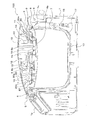
図1は、本発明の実施の形態1に係る炊飯器100の外観を示す斜視図である。図2は、本発明の実施の形態1に係る炊飯器100の概略構成を示す説明図である。
図1、図2に示すように、実施の形態1に係る炊飯器100は、本体1を備える。
本体1の上部には、上部開口部が形成されている。上部開口部は、本体1にヒンジ3で軸連結された上部開口部を覆う蓋体2によって開閉される。
蓋体2は、ラッチ4とラッチ解除ボタン5とによって、開閉される。
Embodiment 1 FIG.
FIG. 1 is a perspective view showing an appearance of
As shown in FIGS. 1 and 2, the
An upper opening is formed in the upper part of the main body 1. The upper opening is opened and closed by a
The
本体1の軸連結されたヒンジ3を有する側と反対側の前面には、表示部1aおよび操作ボタン1bが設けられている。
A
蓋体2の下面には、内蓋6が着脱可能に設けられている。内蓋6は、内釜7の開口部をシールする環状のパッキン8を固定した固定枠9に固定される。
An
蓋体2と内蓋6との間には、内蓋6側の表面を板金10で覆われたヒータ11が設けられている。ヒータ11は、給電されると抵抗加熱で発熱する。ヒータ11は、蓋体2に這わせた線状のヒータである。なお、ヒータ11は、線状のヒータではなく、面状のヒータであってもよい。
A
蓋体2の内蓋6よりも上側には、蒸気に混入するおねばを分離するおねば分離ケース12が取り付けられている。おねば分離ケース12には、内蓋6の蒸気流入孔6aの上方に案内筒13および開閉弁19が設けられている。案内筒13の蒸気孔14から流入した蒸気は、蓋体2のおねば分離ケース12を経て、蓋体2上部の蒸気排出孔15から外部に放出される。加熱が停止して内釜7の内圧が低下して開閉弁19が開弁すると、おねばが内釜7に戻される。
おねば分離ケース12は、炊飯中に発生する蒸気とおねばとを分離し、蒸気を蒸気排出孔15に導くと共に、おねばを内釜7に戻す機能を有する。
On the upper side of the
The rice
また、蓋体2には、温度センサ18が設置されている。温度センサ18は、ヒータ11とおねば分離ケース12との間に配置されている。
The
炊飯器100は、本体1内にコイル台となる内釜収容部16を備えており、内釜収容部16には、水、米などが入れられる有底筒状の内釜7が着脱自在に収容される。内釜7は、内釜収容部16の下面の中心部の周りとその外周のコーナー部に配置された加熱手段としての電磁誘導コイル17により加熱され炊飯される。
The
内釜7は、上端に外径方向に延出されたフランジ7aが形成される。フランジ7aは、内釜収容部16への収容時に、内釜収容部16の上端に載置されて支持される。また、内釜7は、蓋体2の閉時に、内蓋6側に設けたパッキン8がフランジ7aの上面に押圧されることによって密閉される。
The
次に、内蓋6について詳述する。
内蓋6は、たとえば、アルミナ素材、ジルコニア素材、SiC素材などの多孔質セラミックスの素材から形成されている。多孔質セラミックスの素材から形成された内蓋6は、連続気泡体となっており、内部に無数の微細な孔が空き、材料を高温で焼いて固めて焼成したものである。内蓋6に形成される微細な孔は、孔同士が繋がり孔同士の壁に小孔が開き、内蓋6の表面に結露した水滴を保水可能である。
Next, the
The
内蓋6の形状は、全体として蓋体2に固定された外周縁部から中心部を下方の内釜7側に凸状としたお椀状の曲面形状である。ただし、内蓋6の中央部の一部の形状は、おねば分離ケース12および温度センサ18を上方に有する部分を上方に凹ませている。内蓋6のおねば分離ケース12を上方に有する部分は、複数の蒸気流入孔6aを有した平坦部6bとなっている。内蓋6の温度センサ18を上方に有する部分は、おねば分離ケース12を上方に有する部分よりも上方に位置する平坦部6cとなって温度センサ18が精度良く温度を検知できるようにしている。
The shape of the
次に、上記のような内蓋6を取り付けた炊飯器100により炊飯する場合の作用について説明する。
水と米を入れた内釜7を炊飯器100の本体1内に収容して蓋体2を閉じ、操作ボタン1bに設けた電源スイッチをONすると、電磁誘導コイル17の作用によって内釜7が加熱される。内釜7内の水が沸騰すると、おねばを含んだ蒸気が発生する。このとき、内釜7の内圧が上昇しているため、おねば分離ケース12の開閉弁19は、押し上げられておねば戻し孔を閉塞しており、このため、おねばを含む蒸気は、蒸気孔14から案内筒13を通って、おねば分離ケース12内に導かれる。おねば分離ケース12は、炊飯中に発生する蒸気とおねばとを分離し、蒸気を蒸気排出孔15に導く。そして、加熱が停止して内釜7の内圧が低下すると、開閉弁19が自重およびおねばの重量によって下降して開弁し、おねばを内釜7に戻す。
Next, an effect | action at the time of cooking with the
When the
一方、内釜7内の蒸気は、内蓋6に結露すると、結露した水滴が多孔質セラミックスの素材で形成された内蓋6自体の孔内に染み込んで保水され、ご飯への滴下を抑える。内蓋6は、中心側が内釜7側に凸状の曲面形状であることによって、表面積を増大させ、内蓋6自体が孔内に保水できる保水能力を向上している。
On the other hand, when the steam in the
次に、上記のような内蓋6を取り付けた炊飯器100により保温する場合の作用について説明する。
保温中には、内釜7内の湿度が下がる。このとき、内蓋6は、炊飯時に多孔質セラミックスの素材で形成された内蓋6自体の孔内に保水しているため、ヒータ11によって加熱されると内蓋6の孔内に保水している水を放出する。そして、保温中のご飯の乾きを抑制することができる。
Next, an effect | action at the time of heat-retaining with the
During the heat insulation, the humidity in the
実施の形態2.
実施の形態2では、内蓋6の内釜7側の表面には、複数の凹部20が形成されている。その他の構成は、実施の形態1と同様であるので、その特徴部分のみを説明する。
In the second embodiment, a plurality of
図3は、本発明の実施の形態2に係る炊飯器100の概略構成を示す説明図である。
内蓋6の内釜7側の表面には、複数の凹部20が形成されている。また、内蓋6の蓋体2側の表面には、複数の凹部20が内蓋6の厚みを変えずに、内釜7側の下方に対して凹みつつ、内蓋6の蓋体2側の表面より凹部20の底部20aが突出している。また、蓋体2に這わせた線状のヒータ11は、底部20aの上方に位置している。このため、蓋体2側の表面において、凹部20が形成されていない箇所よりも底部20aがヒータ11に近接するように、凹部20は形成されている。複数の凹部20は、ヒータ11と互いに沿うように配設されている。このため、複数の凹部20の底部20aは、ヒータ11に近接した状態でヒータ11に沿っている。
FIG. 3 is an explanatory diagram showing a schematic configuration of the
A plurality of
実施の形態2では、内蓋6の内釜7側の表面に複数の凹部20が形成されていることによって、中心側を内釜7側に凸状の曲面形状であることに加えて更に表面積を増大させ、内蓋6自体が孔内に保水できる保水能力を向上している。また、内蓋6の一部がヒータ11に近接し、保温中に内釜7内の湿度が下がったときには、内蓋6自体が孔内に保水している水を放出し易い。
In the second embodiment, a plurality of
以上説明した実施の形態1、2によれば、内蓋6を多孔質セラミックスの素材で形成していることによって、炊飯中および保温中に内蓋6に結露する水滴を内蓋6自体が孔内に染み込んで保水し、ご飯への滴下を抑え、おいしさを損なうことがない。また、保温中に内釜7内の湿度が下がったときには、内蓋6自体が孔内に保水している水を放出し、ご飯の乾きを抑制する。したがって、内蓋6を多孔質セラミックスの素材で形成するという技術的に単純でコストがかからない構成であり、内蓋6に結露した水滴をご飯に滴下させることを抑制することができ、保温中のご飯の乾きを抑制することができる。
According to the first and second embodiments described above, since the
また、多孔質セラミックスは、焼成によってたとえば反り返ったりして形状のばらつきが大きく安定しない欠点がある。具体的には、平板状である多孔質セラミックスが焼成によって反り返る方向が一定方向ではなく、表裏どちら側にも反り返ったりして形状がばらつく。しかし、実施の形態1、2に係る炊飯器100の内蓋6の形状は、中心側を下方の内釜7側に凸状の曲面形状であることによって、焼成時の反り返りが本来の形状に反映され、中心側を下方の内釜7側に凸状となる一定方向にのみ反り返りが許容され、形状のばらつきを少なく安定させることができる。
In addition, porous ceramics have a disadvantage that they are warped by firing, for example, and have a large variation in shape and are not stable. Specifically, the direction in which flat porous ceramics are warped by firing is not a fixed direction, and the shape is varied by warping on either the front or back side. However, the shape of the
また、内蓋6の形状は、中心側を下方の内釜7側に凸状の曲面形状であることによって、表面積を増大させ、内蓋6自体が孔内に保水できる保水能力を向上している。また、内蓋6の形状は、中心側を下方の内釜7側に凸状の曲面形状であることによって、逆に下方の内釜7側に凹状の曲面形状であると外周端部が内釜7側に鋭角に突出して損傷し易い突出部を有してしまう点を解消でき、内蓋6が損傷し難く使用耐久性が向上する。
In addition, the shape of the
内蓋6の内釜7側の表面には、複数の凹部20が形成されている。この凹部20を形成していることにより、内蓋6の表面積を増大させ、内蓋6自体が孔内に保水できる保水能力を向上している。
A plurality of
内蓋6の内釜7側の表面に形成された複数の凹部20は、凹部20の底部20aがヒータ11に近接するように内蓋6の蓋体2側の表面より突出して形成されている。このように凹部20を形成していることで、内蓋6の一部がヒータ11に近接し、保温中の内蓋6自体が孔内に保水している水の放出の作用を能動的かつ効率的に行うことができる。
The plurality of
ヒータ11と複数の凹部20とは、互いに沿うように配設されている。このようにヒータ11と複数の凹部20とを配設していることで、内蓋6の一部がヒータ11に近接し、保温中の内蓋6自体が孔内に保水している水の放出の作用をより能動的かつ効率的に行うことができる。
The
なお、上記実施の形態では、内蓋6の内釜7側の表面には、ヒータ11と互いに沿うように複数の溝状の凹部20が形成されている。しかし、凹部の形状並びに凹部の数はこれに限られない。たとえば、内蓋の内釜側の表面には、ヒータに沿って断続的に複数の円形状の凹部が形成されていてもよいし、ヒータに沿うように1つの溝状の凹部が形成されていてもよい。また、凹部は、内蓋の表面積を増大させる目的でヒータに近接させずに設けてもよい。さらに、内蓋の表面積を増大させる目的であれば、凹部の代わりに、内蓋の内釜側の表面より突出する凸部を設けても同様の目的を達成することができる。
In the above embodiment, a plurality of groove-shaped
なお、今回開示された実施の形態はすべての点で例示であって制限的なものではないと考えられるべきである。本発明の範囲は上記した説明ではなくて特許請求の範囲によって示され、特許請求の範囲と均等の意味および範囲内でのすべての変更が含まれることが意図される。 The embodiment disclosed this time should be considered as illustrative in all points and not restrictive. The scope of the present invention is defined by the terms of the claims, rather than the description above, and is intended to include any modifications within the scope and meaning equivalent to the terms of the claims.
1 本体、1a 表示部、1b 操作ボタン、2 蓋体、3 ヒンジ、4 ラッチ、5 ラッチ解除ボタン、6 内蓋、6a 蒸気流入孔、6b 平坦部、6c 平坦部、7 内釜、7a フランジ、8 パッキン、9 固定枠、10 板金、11 ヒータ、12 おねば分離ケース、13 案内筒、14 蒸気孔、15 蒸気排出孔、16 内釜収容部、17 電磁誘導コイル、18 温度センサ、19 開閉弁、20 凹部、20a 底部、100 炊飯器。 DESCRIPTION OF SYMBOLS 1 Main body, 1a Display part, 1b Operation button, 2 Cover body, 3 Hinge, 4 Latch, 5 Latch release button, 6 Inner lid, 6a Steam inlet, 6b Flat part, 6c Flat part, 7 Inner hook, 7a Flange, 8 Packing, 9 Fixed frame, 10 Sheet metal, 11 Heater, 12 Large separation case, 13 Guide tube, 14 Steam hole, 15 Steam discharge hole, 16 Inner hook housing part, 17 Electromagnetic induction coil, 18 Temperature sensor, 19 Open / close valve , 20 recess, 20a bottom, 100 rice cooker.
Claims (5)
前記内蓋は、多孔質セラミックスの素材から形成されている炊飯器。 A main body that houses the inner hook, a lid that is hinged to the main body and covers the upper opening of the main body, a heating means that heats the inner hook, and an inner body attached to the inner hook side of the lid A rice cooker comprising a lid,
The inner lid is a rice cooker formed of a porous ceramic material.
前記内蓋には、前記凹部の底部が前記ヒータに近接するように前記内蓋の前記蓋体側の表面より突出して形成されている請求項3に記載の炊飯器。 A heater is provided between the lid and the inner lid,
The rice cooker according to claim 3, wherein the inner lid is formed so as to protrude from a surface of the inner lid on the lid side so that a bottom portion of the recess is close to the heater.
Priority Applications (1)
| Application Number | Priority Date | Filing Date | Title |
|---|---|---|---|
| JP2015177578A JP2017051417A (en) | 2015-09-09 | 2015-09-09 | rice cooker |
Applications Claiming Priority (1)
| Application Number | Priority Date | Filing Date | Title |
|---|---|---|---|
| JP2015177578A JP2017051417A (en) | 2015-09-09 | 2015-09-09 | rice cooker |
Publications (1)
| Publication Number | Publication Date |
|---|---|
| JP2017051417A true JP2017051417A (en) | 2017-03-16 |
Family
ID=58316035
Family Applications (1)
| Application Number | Title | Priority Date | Filing Date |
|---|---|---|---|
| JP2015177578A Pending JP2017051417A (en) | 2015-09-09 | 2015-09-09 | rice cooker |
Country Status (1)
| Country | Link |
|---|---|
| JP (1) | JP2017051417A (en) |
Cited By (2)
| Publication number | Priority date | Publication date | Assignee | Title |
|---|---|---|---|---|
| CN110916482A (en) * | 2019-12-30 | 2020-03-27 | 南京工业职业技术学院 | A multipurpose rice cooker |
| CN110946465A (en) * | 2019-12-30 | 2020-04-03 | 南京工业职业技术学院 | Tilting draining type electric cooker |
-
2015
- 2015-09-09 JP JP2015177578A patent/JP2017051417A/en active Pending
Cited By (2)
| Publication number | Priority date | Publication date | Assignee | Title |
|---|---|---|---|---|
| CN110916482A (en) * | 2019-12-30 | 2020-03-27 | 南京工业职业技术学院 | A multipurpose rice cooker |
| CN110946465A (en) * | 2019-12-30 | 2020-04-03 | 南京工业职业技术学院 | Tilting draining type electric cooker |
Similar Documents
| Publication | Publication Date | Title |
|---|---|---|
| JP2005304709A (en) | Induction heating rice cooker | |
| KR102351771B1 (en) | electric rice cooker | |
| JP2022010420A (en) | rice cooker | |
| KR101536219B1 (en) | Ceramics pot | |
| JP2017189628A (en) | Steaming device for cooking pot and rice cooker using steaming device | |
| JP2009285231A (en) | Rice cooker | |
| JP6784030B2 (en) | Cooker | |
| JP6524248B2 (en) | rice cooker | |
| JP3200806U (en) | Steam cooking pot | |
| US20200337500A1 (en) | Cooking vessel with an opening for drainage | |
| JP2002142975A (en) | rice cooker | |
| KR101805145B1 (en) | Pot assembly | |
| JP4961387B2 (en) | rice cooker | |
| JP6175802B2 (en) | Steamer for cooking pot and rice cooker using steamer | |
| WO2017145414A1 (en) | Rice cooker | |
| CN209172033U (en) | Pot cover component and cooking apparatus | |
| JP2018153360A (en) | rice cooker | |
| JP2021053275A (en) | Heat-retention cooking device | |
| CN105286492A (en) | Steaming and stewing utensil component for microwave ovens | |
| KR101430345B1 (en) | Smell Reducing type Dual Cooking Pot | |
| KR20210097970A (en) | Pot with enhanced thermal efficiency | |
| KR20190001201U (en) | Double structure pot with slow cooking | |
| JP4877357B2 (en) | Steamer for rice cooker | |
| KR20170001961U (en) | Cooking Utensils for Induction stove | |
| JP3190410U (en) | Induction cooker with kettle |