JP2017018169A - Display method and display chart of swing of golf club - Google Patents
Display method and display chart of swing of golf club Download PDFInfo
- Publication number
- JP2017018169A JP2017018169A JP2015136200A JP2015136200A JP2017018169A JP 2017018169 A JP2017018169 A JP 2017018169A JP 2015136200 A JP2015136200 A JP 2015136200A JP 2015136200 A JP2015136200 A JP 2015136200A JP 2017018169 A JP2017018169 A JP 2017018169A
- Authority
- JP
- Japan
- Prior art keywords
- golf club
- angle
- area
- axis
- golf
- Prior art date
- Legal status (The legal status is an assumption and is not a legal conclusion. Google has not performed a legal analysis and makes no representation as to the accuracy of the status listed.)
- Granted
Links
Images


Classifications
-
- A—HUMAN NECESSITIES
- A63—SPORTS; GAMES; AMUSEMENTS
- A63B—APPARATUS FOR PHYSICAL TRAINING, GYMNASTICS, SWIMMING, CLIMBING, OR FENCING; BALL GAMES; TRAINING EQUIPMENT
- A63B71/00—Games or sports accessories not covered in groups A63B1/00 - A63B69/00
- A63B71/06—Indicating or scoring devices for games or players, or for other sports activities
- A63B71/0619—Displays, user interfaces and indicating devices, specially adapted for sport equipment, e.g. display mounted on treadmills
- A63B71/0622—Visual, audio or audio-visual systems for entertaining, instructing or motivating the user
-
- A—HUMAN NECESSITIES
- A63—SPORTS; GAMES; AMUSEMENTS
- A63B—APPARATUS FOR PHYSICAL TRAINING, GYMNASTICS, SWIMMING, CLIMBING, OR FENCING; BALL GAMES; TRAINING EQUIPMENT
- A63B69/00—Training appliances or apparatus for special sports
- A63B69/36—Training appliances or apparatus for special sports for golf
- A63B69/3623—Training appliances or apparatus for special sports for golf for driving
-
- A—HUMAN NECESSITIES
- A63—SPORTS; GAMES; AMUSEMENTS
- A63B—APPARATUS FOR PHYSICAL TRAINING, GYMNASTICS, SWIMMING, CLIMBING, OR FENCING; BALL GAMES; TRAINING EQUIPMENT
- A63B24/00—Electric or electronic controls for exercising apparatus of preceding groups; Controlling or monitoring of exercises, sportive games, training or athletic performances
- A63B24/0003—Analysing the course of a movement or motion sequences during an exercise or trainings sequence, e.g. swing for golf or tennis
-
- A—HUMAN NECESSITIES
- A63—SPORTS; GAMES; AMUSEMENTS
- A63B—APPARATUS FOR PHYSICAL TRAINING, GYMNASTICS, SWIMMING, CLIMBING, OR FENCING; BALL GAMES; TRAINING EQUIPMENT
- A63B57/00—Golfing accessories
-
- A—HUMAN NECESSITIES
- A63—SPORTS; GAMES; AMUSEMENTS
- A63B—APPARATUS FOR PHYSICAL TRAINING, GYMNASTICS, SWIMMING, CLIMBING, OR FENCING; BALL GAMES; TRAINING EQUIPMENT
- A63B60/00—Details or accessories of golf clubs, bats, rackets or the like
- A63B60/46—Measurement devices associated with golf clubs, bats, rackets or the like for measuring physical parameters relating to sporting activity, e.g. baseball bats with impact indicators or bracelets for measuring the golf swing
-
- A—HUMAN NECESSITIES
- A63—SPORTS; GAMES; AMUSEMENTS
- A63B—APPARATUS FOR PHYSICAL TRAINING, GYMNASTICS, SWIMMING, CLIMBING, OR FENCING; BALL GAMES; TRAINING EQUIPMENT
- A63B69/00—Training appliances or apparatus for special sports
- A63B69/36—Training appliances or apparatus for special sports for golf
- A63B69/3614—Training appliances or apparatus for special sports for golf using electro-magnetic, magnetic or ultrasonic radiation emitted, reflected or interrupted by the golf club
-
- G—PHYSICS
- G06—COMPUTING; CALCULATING OR COUNTING
- G06F—ELECTRIC DIGITAL DATA PROCESSING
- G06F17/00—Digital computing or data processing equipment or methods, specially adapted for specific functions
-
- A—HUMAN NECESSITIES
- A63—SPORTS; GAMES; AMUSEMENTS
- A63B—APPARATUS FOR PHYSICAL TRAINING, GYMNASTICS, SWIMMING, CLIMBING, OR FENCING; BALL GAMES; TRAINING EQUIPMENT
- A63B2102/00—Application of clubs, bats, rackets or the like to the sporting activity ; particular sports involving the use of balls and clubs, bats, rackets, or the like
- A63B2102/32—Golf
-
- A—HUMAN NECESSITIES
- A63—SPORTS; GAMES; AMUSEMENTS
- A63B—APPARATUS FOR PHYSICAL TRAINING, GYMNASTICS, SWIMMING, CLIMBING, OR FENCING; BALL GAMES; TRAINING EQUIPMENT
- A63B2220/00—Measuring of physical parameters relating to sporting activity
- A63B2220/80—Special sensors, transducers or devices therefor
- A63B2220/805—Optical or opto-electronic sensors
-
- A—HUMAN NECESSITIES
- A63—SPORTS; GAMES; AMUSEMENTS
- A63B—APPARATUS FOR PHYSICAL TRAINING, GYMNASTICS, SWIMMING, CLIMBING, OR FENCING; BALL GAMES; TRAINING EQUIPMENT
- A63B2220/00—Measuring of physical parameters relating to sporting activity
- A63B2220/80—Special sensors, transducers or devices therefor
- A63B2220/83—Special sensors, transducers or devices therefor characterised by the position of the sensor
- A63B2220/833—Sensors arranged on the exercise apparatus or sports implement
Abstract
Description
本発明は、ゴルフクラブのスウィングの表示方法および表示図表に関する。 The present invention relates to a golf club swing display method and display chart.
従来、ゴルフスウィングを計測し解析する方法として、カメラでゴルフスウィングを撮影し、その撮影画像からゴルフクラブヘッドの挙動を解析して、ゴルフスウィングの特徴を抽出する方法や、磁気センサでゴルフクラブヘッドの挙動を直接計測する方法や、所定の位置に配置した複数の光ビームをゴルフクラブヘッドが横切って通過することを感知するインタラプタ式光センサを用いて、ゴルフクラブヘッドの挙動を計測する方法が挙げられる。
これらは、いずれもゴルフクラブヘッドの概略の軌道を計測することはできるが、ゴルフボールの球筋を定めるゴルフボールの打撃直前のゴルフクラブヘッドの挙動を正確に把握することができないものであった。
Conventionally, as a method of measuring and analyzing a golf swing, a method of capturing a golf swing with a camera, analyzing a behavior of the golf club head from the captured image, and extracting a feature of the golf swing, or a golf club head with a magnetic sensor A method for directly measuring the behavior of a golf club, or a method for measuring the behavior of a golf club head using an interrupter type optical sensor that senses that a plurality of light beams arranged at predetermined positions pass across the golf club head. Can be mentioned.
All of these can measure the approximate trajectory of the golf club head, but cannot accurately grasp the behavior of the golf club head immediately before the golf ball hitting the golf ball.
一方、下記特許文献1、2には、ゴルフボールの打撃時のゴルフクラブの挙動を計測することのできる装置が記載されている。
特許文献1の[0023]に記載されているように、4つのセンサを配置することにより、ゴルフボールに対するゴルフクラブヘッドの入射角度を概略的に知ることができる。特許文献2についても同様に、4つのセンサを配置することにより、ゴルフボールに対するゴルフクラブヘッドの入射角度を概略的に知ることができる。
しかし、特許文献1、2によるゴルフクラブの挙動の計測では、ゴルフクラブヘッドのゴルフボールに対する入射角度を概略的に知ることはできても、ゴルフボールのフックやスライス等の球筋に影響を与えるゴルフクラブのスウィングの特徴を簡単に理解することは困難であった。
On the other hand,
As described in [0023] of
However, in the measurement of the behavior of the golf club according to
そこで、本出願人は、球筋に影響を与えるスウィングの特徴を簡単にかつわかりやすくすることができるゴルフクラブのスウィングの表示方法を提案した(特許文献3参照)。
この表示方法では、ゴルフボールの中心と目標とを結ぶ目標線を水平面と平行な平面に投影した基準線とゴルフボールを打撃する直前におけるゴルフクラブヘッドの移動軌跡に対する接線を平面に投影した第1の直線とがなす角度を左右進入角とする。
また、基準線とゴルフボールを打撃する直前におけるゴルフクラブヘッドのフェース面の中心点を通る法線を平面に投影した第2の直線とがなす角度を打撃時フェース角とする。
そして、左右進入角を示すX軸と、X軸に直交し打撃時フェース角を示すY軸とを備え、それらX軸、Y軸の交点を左右進入角および打撃時フェース角のゼロ度として形成された2次元座標と、2次元座標上に、球筋の傾向に応じて境界分けされた複数のエリアを表示画面上に表示する。
複数のエリアは、例えば、スライスエリア、フェードエリア、フックエリア、ドローエリア、ストレートエリアである。
そして、表示画面に、ゴルファがゴルフクラブを用いてゴルフボールを打った際に測定した左右進入角の値と打撃時フェース角の値とを示す座標点を測定点として表示する。
Therefore, the present applicant has proposed a swing display method for a golf club that makes it easy and easy to understand the characteristics of the swing that affects the ball muscle (see Patent Document 3).
In this display method, a reference line obtained by projecting a target line connecting the center of the golf ball and the target onto a plane parallel to the horizontal plane and a tangent line to the movement locus of the golf club head immediately before hitting the golf ball are projected onto the plane. The angle formed by the straight line is the left / right approach angle.
The angle formed between the reference line and the second straight line projected on the plane from the normal line passing through the center point of the face surface of the golf club head immediately before hitting the golf ball is defined as the face angle at the time of hitting.
An X axis indicating the left and right approach angle and a Y axis perpendicular to the X axis and indicating the face angle at the time of hitting are formed, and the intersection of the X axis and the Y axis is formed as a zero degree of the left and right approach angle and the face angle at the time of hitting. On the display screen, the two-dimensional coordinates and a plurality of areas divided according to the tendency of the spherical muscles are displayed on the two-dimensional coordinates.
The plurality of areas are, for example, a slice area, a fade area, a hook area, a draw area, and a straight area.
Then, on the display screen, coordinate points indicating the value of the left and right approach angle measured when the golfer hits the golf ball using the golf club and the value of the face angle at the time of hitting are displayed as measurement points.
上記従来技術によれば、ゴルフボールのフックやスライス等の球筋に影響を与えるスウィングの特徴を簡単にかつわかりやすく表示する上で有利である。
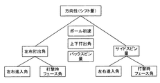
ところで、ゴルフボールの球筋は、基準線から着弾地点までの距離(シフト量)が近いほど良い評価となる。
上記従来技術では、ゴルフボールが打撃される際の左右進入角と打撃時フェース角とを考慮して球筋を評価しているものの、実際のゴルフボールの移動軌跡、言い換えるとシフト量に影響を与える、打撃されたゴルフボールの左右打ち出し角と、打撃されたゴルフボールのサイドスピン量とについては充分には考慮されていない。
そのため、上記従来技術では、基準線から着弾地点までの距離(シフト量)をより正確に評価する上で改善の余地がある。
本発明は、このような事情に鑑みてなされたものであり、その目的は、ゴルフボールの着弾地点の位置に影響を与えるスウィングの特徴を的確に提供する上で有利なゴルフクラブのスウィングの表示方法および表示図表を提供することを目的とする。
According to the above-described conventional technology, it is advantageous in displaying swing characteristics that affect the ball muscles such as hooks and slices of a golf ball in a simple and easy-to-understand manner.
By the way, the ball of the golf ball has a better evaluation as the distance (shift amount) from the reference line to the landing point is shorter.
In the above prior art, although the ball muscle is evaluated in consideration of the left and right approach angle when the golf ball is hit and the face angle at the time of hitting, the actual trajectory of the golf ball, in other words, the shift amount is affected. The left and right launch angles of the hit golf ball and the side spin amount of the hit golf ball are not sufficiently considered.
For this reason, the conventional technology has room for improvement in evaluating the distance (shift amount) from the reference line to the landing point more accurately.
The present invention has been made in view of such circumstances, and an object of the present invention is to display a swing of a golf club that is advantageous in accurately providing a swing feature that affects the position of a landing point of a golf ball. The object is to provide a method and display chart.
上記目的を達成するために、本発明は、ゴルファによりスウィングされたゴルフクラブのゴルフクラブヘッドがゴルフボールを打撃する直前におけるゴルフクラブヘッドの挙動に基づいて測定されたスウィングの特徴を表示装置に表示するゴルフクラブのスウィングの表示方法であって、前記ゴルフボールの中心と目標とを結ぶ目標線を水平面と平行な平面に投影した基準線と、前記ゴルフボールを打撃する直前における前記ゴルフクラブヘッドの移動軌跡に対する接線を前記平面に投影した第1の直線とがなす角度を左右進入角とし、前記左右進入角の正負は、前記基準線を中心としてゴルファの反対側を正の角度とし、ゴルファ側を負の角度とし、前記基準線と前記ゴルフボールを打撃する直前における前記ゴルフクラブヘッドのフェース面の中心点を通る法線を前記平面に投影した第2の直線とがなす角度を打撃時フェース角とし、前記打撃時フェース角の正負は、前記基準線を中心としてゴルファの反対側を正の角度とし、ゴルファ側を負の角度とし、前記ゴルファによりスウィングされたゴルフクラブのゴルフクラブヘッドによって打撃されて打ち出された直後のゴルフボールの軌跡を前記平面に投影した線と前記基準線とがなす角度を左右打ち出し角とし、前記左右打ち出し角の正負は、前記基準線を中心としてゴルファの反対側を正の角度とし、ゴルファ側を負の角度とし、前記ゴルファによりスウィングされたゴルフクラブのゴルフクラブヘッドによって打撃されて打ち出された直後のゴルフボールの中心を通る鉛直線回りのスピン量をサイドスピン量として、前記サイドスピン量の正負は、平面視時計回りを正とし、反時計回りを負とし、前記左右進入角と前記打撃時フェース角との測定値から、前記左右打ち出し角および前記サイドスピン量を推定する推定ステップと、前記推定された左右打ち出し角および前記サイドスピン量と、前記ゴルフボールのボール初速と、前記ゴルフボールの上下打ち出し角とに基いて前記ゴルフボールの移動軌跡をシミュレーションして前記基準線から着弾地点までの距離であるシフト量を算出するシミュレーションステップと、前記推定ステップと前記シミュレーションステップとを繰り返すことで前記左右進入角と前記打撃時フェース角と前記シフト量とからなるデータを蓄積し、蓄積されたデータに基いて、前記左右進入角を示すX軸と、前記X軸に直交し前記打撃時フェース角を示すY軸と、それらX軸、Y軸の交点を前記左右進入角および前記打撃時フェース角のゼロ度とした2次元座標上に、前記左右進入角と前記打撃時フェース角と前記シフト量とに基いて特定される球筋の傾向に応じて境界分けされた複数のエリアを規定した分類マップを作成する分類マップ作成ステップと、前記表示装置の表示画面に、前記2次元座標軸を表示する座標軸表示ステップと、前記表示画面に、前記分類マップに基いて複数のエリアを表示する各種エリア表示ステップと、前記表示画面に、ゴルファがゴルフクラブを用いてゴルフボールを打った際に測定した前記左右進入角の値と前記打撃時フェース角の値とを示す座標点を測定点として表示する測定点表示ステップとを含むことを特徴とする。
また本発明は、ゴルファによりスウィングされたゴルフクラブのゴルフクラブヘッドがゴルフボールを打撃する直前におけるゴルフクラブヘッドの挙動に基づいて測定されたスウィングの特徴を表示するゴルフクラブのスウィングの表示図表であって、前記ゴルフボールの中心と目標とを結ぶ目標線を水平面と平行な平面に投影した基準線と、前記ゴルフボールを打撃する直前における前記ゴルフクラブヘッドの移動軌跡に対する接線を前記平面に投影した第1の直線とがなす角度を左右進入角とし、前記左右進入角の正負は、前記基準線を中心としてゴルファの反対側を正の角度とし、ゴルファ側を負の角度とし、前記基準線と前記ゴルフボールを打撃する直前における前記ゴルフクラブヘッドのフェース面の中心点を通る法線を前記平面に投影した第2の直線とがなす角度を打撃時フェース角とし、前記打撃時フェース角の正負は、前記基準線を中心としてゴルファの反対側を正の角度とし、ゴルファ側を負の角度とした場合、前記左右進入角を示すX軸と、前記X軸に直交し前記打撃時フェース角を示すY軸とを備え、それらX軸、Y軸の交点を前記左右進入角および前記打撃時フェース角のゼロ度として形成された2次元座標と、前記2次元座標上に、球筋の傾向に応じて境界分けされた複数のエリアとを有し、前記2次元座標軸においてX軸およびY軸と交差して正の傾きで延在する前記シフト量がゼロに対応する直線からなる第1の境界線と、前記2次元座標軸において前記第1の境界線と交差し前記第1の境界線よりも大きい正の傾きで延在する前記サイドスピン量がゼロに対応する直線からなる第2の境界線とが設けられ、前記球筋の傾向に応じて境界分けされた複数のエリアは、前記第1の境界線と前記第2の境界線で挟まれた2つの領域のうち、X軸およびY軸の正方向寄りに位置する領域に表示されるドローエリアと、前記第1の境界線と前記第2の境界線で挟まれた2つの領域のうち、X軸およびY軸の負方向寄りに位置する領域に表示されるフェードエリアと、前記ドローエリアおよび前記フェードエリアよりもY軸の正方向側に位置する領域に表示されるスライスエリアと、前記ドローエリアおよび前記フェードエリアよりもY軸の負方向側に位置する領域に表示されるフックエリアと、前記第2の境界線に表示されたストレートエリアとを含んで構成されていることを特徴とする。
In order to achieve the above object, the present invention displays on a display device swing characteristics measured based on the behavior of a golf club head immediately before the golf club head of a golf club swung by a golfer hits a golf ball. A method for displaying a swing of a golf club, comprising: a reference line obtained by projecting a target line connecting the center of the golf ball and a target onto a plane parallel to a horizontal plane; and the golf club head immediately before hitting the golf ball. The angle formed by the first straight line projected on the plane with the tangent to the movement trajectory is the left and right approach angle, and the sign of the left and right approach angle is the positive angle on the opposite side of the golfer with the reference line as the center. Is a negative angle, and the golf club head fades immediately before hitting the golf ball with the reference line. The angle formed by the normal line passing through the center point of the surface and the second straight line projected on the plane is the face angle at the time of hitting, and the positive / negative of the face angle at the time of hitting is positive on the opposite side of the golfer around the reference line. A line obtained by projecting a trajectory of a golf ball immediately after being hit by a golf club head of a golf club swung by the golfer onto the plane and the reference line. The golf ball of the golf club swung by the golfer has a left and right launch angle, and the positive and negative of the left and right launch angle is a positive angle on the opposite side of the golfer around the reference line and a negative angle on the golfer side. The amount of spin around the vertical line passing through the center of the golf ball immediately after being hit by the club head is taken as the amount of side spin. The positive or negative side spin amount is positive in the clockwise direction in plan view, negative in the counterclockwise direction, and the left and right launch angles and the side spin amount are estimated from the measured values of the left and right approach angles and the hitting face angle. Based on the estimation step, the estimated left and right launch angle and the side spin amount, the initial ball velocity of the golf ball, and the up and down launch angle of the golf ball, the movement trajectory of the golf ball is simulated and the reference line By repeating the simulation step for calculating the shift amount that is the distance from the landing point to the landing point, the estimation step, and the simulation step, data including the left and right approach angles, the striking face angle, and the shift amount is accumulated. Based on the accumulated data, the X axis indicating the left and right approach angles, and The left and right approach angles and the striking face angle on a two-dimensional coordinate with the Y axis indicating the striking face angle and the intersection of the X axis and Y axis as the left and right approach angles and the zero angle of the striking face angle. A classification map creating step for creating a classification map that defines a plurality of areas demarcated according to the tendency of the spherical muscle specified based on the shift amount and the two-dimensional coordinate axes on the display screen of the display device A coordinate axis display step for displaying the image, various area display steps for displaying a plurality of areas on the display screen based on the classification map, and when the golfer hits a golf ball using a golf club on the display screen. And a measurement point display step of displaying, as measurement points, coordinate points indicating the measured value of the left and right approach angle and the value of the face angle at the time of hitting.
Further, the present invention is a golf club swing display chart displaying swing characteristics measured based on the behavior of the golf club head immediately before the golf club head of the golf club swung by the golfer hits the golf ball. Then, a reference line obtained by projecting a target line connecting the center of the golf ball and the target onto a plane parallel to a horizontal plane and a tangent to the movement track of the golf club head immediately before hitting the golf ball are projected onto the plane. The angle formed by the first straight line is a left and right approach angle, and the positive and negative of the left and right approach angle is a positive angle on the opposite side of the golfer around the reference line, a negative angle on the golfer side, and the reference line A normal line passing through the center point of the face surface of the golf club head immediately before hitting the golf ball is the plane. The angle formed by the projected second straight line is the face angle at the time of hitting, and the positive / negative of the face angle at the time of hitting is the positive angle on the opposite side of the golfer around the reference line, and the negative angle on the golfer side An X axis indicating the left and right approach angle and a Y axis perpendicular to the X axis and indicating the face angle at the time of hitting, and the intersection of the X axis and the Y axis is the left and right approach angle and the face angle at the time of hitting. Two-dimensional coordinates formed as zero degrees, and a plurality of areas divided on the two-dimensional coordinates according to the tendency of spherical muscles, and intersect the X axis and the Y axis in the two-dimensional coordinate axes. A first boundary line consisting of a straight line corresponding to zero and the shift amount extending with a positive slope, and a positive line that intersects the first boundary line on the two-dimensional coordinate axis and is larger than the first boundary line. The amount of side spin extending with a slope of And a plurality of areas divided according to the tendency of the spherical muscles are sandwiched between the first boundary line and the second boundary line. Of the two areas, the draw area displayed in the area located near the positive direction of the X axis and the Y axis, and the two areas sandwiched between the first boundary line and the second boundary line, A fade area displayed in a region located closer to the negative direction of the X axis and the Y axis, a slice area displayed in a region located on the positive side of the Y axis than the draw area and the fade area, and the draw A hook area displayed in an area located on the negative direction side of the Y axis with respect to the area and the fade area, and a straight area displayed on the second boundary line are included. .
本発明のゴルフクラブのスウィングの表示方法および表示図表によれば、ゴルフボールを打撃する直前におけるゴルフクラブヘッドにおける左右進入角と打撃時フェース角とに基づいて、かつ、左右進入角と打撃時フェース角から推定されるシフト量を考慮して、ゴルフスウィングのタイプを分類するので、ゴルフボールの着弾地点の位置に影響を与えるゴルフスウィングのタイプをより的確に分類する上で有利となる。 According to the golf club swing display method and display chart of the present invention, based on the left and right approach angles and the hitting face angle of the golf club head immediately before hitting the golf ball, and the left and right approaching angles and the hitting face Since the type of golf swing is classified in consideration of the shift amount estimated from the angle, it is advantageous to more accurately classify the type of golf swing that affects the position of the landing point of the golf ball.
以下、本発明のゴルフクラブのスウィングの表示方法が適用されるゴルフクラブの選定装置と、本発明のゴルフクラブのスウィングの表示図表について説明する。
初めに、図1を参照してゴルファがスウィングしたゴルフクラブによって打撃されたゴルフボールの球筋に影響を与える要素について説明する。
ゴルフボールの中心と目標とを結ぶ目標線を水平面と平行な平面に投影した基準線とゴルフボールの着弾地点とを結ぶ最短距離をシフト量とすると、シフト量が低いほど球筋がよいものと評価することができる。
シフト量に影響を与える要素として、後述する左右打ち出し角、サイドスピン量、ボール初速、上下打ち出し角、バックスピン量が挙げられる。
また、左右打ち出し角およびサイドスピン量は、後述するゴルフクラブヘッドの左右進入角θ、打撃時フェース角φによって決定されると考えられる。なお、厳密にいうと、左右打ち出し角およびサイドスピン量は、フェース面上の打点の位置によっても影響されるが、本実施の形態では、打点がフェース面中心であるものとして扱う。
本発明は、左右打ち出し角が左右進入角および打撃時フェース角と相関関係があること、サイドスピン量が左右進入角および打撃時フェース角と相関関係がある点に着目してなされている。
すなわち、本発明は、左右進入角および打撃時フェース角の実測値に基いて、前記の相関関係から推定された左右打ち出し角およびサイドスピン量を用いてゴルフボールの移動軌跡をシミュレーションして着弾地点のシフト量を求め、このシフト量を考慮して球筋の良否を分類、評価するようにしたものである。
Hereinafter, a golf club selection apparatus to which the golf club swing display method of the present invention is applied and a golf club swing display chart of the present invention will be described.
First, with reference to FIG. 1, elements that affect the ball streak of a golf ball hit by a golf club swung by a golfer will be described.
Assume that the shortest distance between the reference line obtained by projecting the target line connecting the center of the golf ball and the target onto a plane parallel to the horizontal plane and the landing point of the golf ball is the shift amount. can do.
Factors that affect the shift amount include the left and right launch angle, side spin amount, ball initial speed, vertical launch angle, and back spin amount, which will be described later.
Further, it is considered that the left and right launch angle and the side spin amount are determined by the left and right approach angle θ and the hitting face angle φ of the golf club head described later. Strictly speaking, the left and right launch angles and the side spin amount are affected by the position of the hit point on the face surface, but in the present embodiment, the hit point is treated as being the center of the face surface.
The present invention is focused on the fact that the left and right launch angles are correlated with the left and right approach angles and the hitting face angle, and the side spin amount is correlated with the left and right approaching angles and the hitting face angle.
That is, the present invention simulates the movement trajectory of the golf ball using the left and right launch angles and the side spin amount estimated from the correlation based on the measured values of the left and right approach angles and the hitting face angle. Shift amount is obtained, and the quality of the ball muscle is classified and evaluated in consideration of this shift amount.
本実施の形態のゴルフクラブの選定装置10の概略構成について説明する。
図2に示すようにゴルフクラブの選定装置10は、照射撮影部11と、制御部12と、コンピュータ14とを含んで構成されている。
照射撮影部11は、異なる2方向からステレオ撮影によりゴルフクラブヘッドを撮影するものである。本実施の形態では、照射撮影部11によって撮影部が構成されている。
制御部12は、照射撮影部11を制御し、照射撮影部11で生成された画像データをコンピュータ14に供給するものである。
コンピュータ14は、照射撮影部11で撮影された画像のデータを取り込み信号処理、画像処理および動作解析を行うともに、ゴルフスウィングをタイプに分類し、最適なゴルフクラブを選定するものである。
なお、図2において符号Pはゴルファ、符号4はゴルフクラブを示す。
A schematic configuration of the golf
As shown in FIG. 2, the golf
The
The
The
In FIG. 2, reference numeral P indicates a golfer, and
次に、ゴルフクラブの選定装置10で計測対象とされるゴルフクラブヘッドについて説明する。
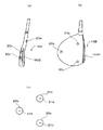
図3(a)はゴルフクラブの選定装置10で計測対象とされるアイアン系のゴルフクラブヘッド16Aを示し、図3(b)はウッド系のゴルフクラブヘッド16Bを示す。
なお、以下では、アイアン系およびウッド系のゴルフクラブヘッドを区別せずに表す場合にはゴルフクラブ16と表記する。
図3(a)に示すように、アイアン系のゴルフクラブヘッド16Aでは、そのフェース面(打撃面)1602と接するゴルフクラブヘッド16の上端面およびホーゼル部にマーカ20a、20b、20cが設けられている。以下、マーカ20a、20b、20cを区別しない場合にはマーカ20と表記する。
また、図3(b)に示されるように、ウッド系のゴルフクラブヘッド16Bのフェース面1602と接するクラウン部を成す上面の3箇所にマーカ20a、20b、20cが設けられている。
後述するカメラ26で撮影した際、マーカ20a、20b、20cの像が常時識別できるように、例えば、マーカ20a、20b、20cは、後述する照射光源22の照射光を反射する再帰反射機能を有する構成となっている。マーカ20a、20b、20cは、例えば、公知の再帰反射シートを所定の形状に切り取ったものである。
マーカ20は、ゴルフクラブヘッドに3箇所以上に設けられ、これらのマーカ20が三角形の頂点を成し、1つの直線上に載らないように配置位置が設定されている。
図3(a)の例では、3つの再帰反射マーカが1つの直線上に載らないように、ホーゼル部にマーカ20が1つ設けられている。
Next, a golf club head to be measured by the golf
FIG. 3A shows an iron-based
In the following, when the iron-based and wood-based golf club heads are expressed without distinction, they are expressed as a
As shown in FIG. 3A, in the iron-based
Further, as shown in FIG. 3B,
For example, the
The
In the example of FIG. 3A, one
本実施の形態においては、後述するようにマーカの位置を求めるため、例えば、マーカから求めた3つ以上のマーカ特徴点を用いる。マーカ特徴点は、マーカを特徴づける点である。
言い換えると、マーカは、ゴルフクラブヘッド16の表面に設けられ3つ以上のマーカ特徴点を有するものである。
例えば、図3(c)に示すように、マーカ20a、20b、20cが円形形状を成す場合、その円形形状の中心点をマーカ特徴点21a〜21cとし、後述する画像処理部32においてその位置が抽出される。
In this embodiment, in order to obtain the position of the marker as will be described later, for example, three or more marker feature points obtained from the marker are used. A marker feature point is a point that characterizes a marker.
In other words, the marker is provided on the surface of the
For example, as shown in FIG. 3C, when the
なお、本発明では、図3(c)に示す本実施の形態の円形状のマーカ20a、20b、20cの形態のほかに、例えば、正三角形、または正方形などの正多角形等とすることができる。この場合、抽出されるマーカ特徴点の位置は各正多角形の場合、マーカの中心点(重心点)とすることができる。
また、各マーカの形状は同一にする必要は無く、前述の形状のものを自在に組み合せる
こともできる。この場合も各マーカの各マーカ特徴点は、例えば、マーカの中心点(重心
点)である。
また、マーカが例えば正三角形形状を成す場合、マーカの3つの頂点(3辺相互の交点)のそれぞれをマーカ特徴点としてもよい。
マーカの形状は特に限定されるものではなく、マーカを特徴付け、その位置が一義的に抽出できる1もしくは複数のマーカ特徴点を有する形状であればよい。
In the present invention, in addition to the
Moreover, the shape of each marker does not need to be the same, The thing of the above-mentioned shape can also be combined freely. Also in this case, each marker feature point of each marker is, for example, the center point (center of gravity) of the marker.
Further, when the marker has, for example, an equilateral triangle shape, each of the three vertexes (intersections of the three sides) of the marker may be used as the marker feature point.
The shape of the marker is not particularly limited as long as it has one or a plurality of marker feature points that characterize the marker and that can be uniquely extracted.
次に、ゴルフクラブの選定装置10について具体的に説明する。
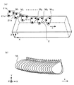
図4は照射撮影部11の斜視図、図5は照射撮影部11の平面図である。
図4、図5に示すように、照射撮影部11は、照射光源22と、ハーフミラー24と、カメラ26と、反射ミラー28と、ベース30とを含んで構成され、これら照射光源22、ハーフミラー24、カメラ26、反射ミラー28は、べース30上に設けられている。
照射光源22は、計測対象としてのゴルフクラブヘッド16を照射するものである。
本実施の形態では、照射光源22はハロゲン光源またはLED光源で構成され、時間的に連続した連続光を照射する。
照射光源22は、ハーフミラー24を介してゴルフクラブヘッド16のマーカ20に光を照射するように配されている。
ハーフミラー24は、光の透過率と反射率とがほぼ等しいミラーであり、ハーフミラー24の反射面(境界面)に入射した光の半分を透過させ残り半分の光を反射させるものである。
ハーフミラー24は、平面視した場合に、その反射面に対して照射光源22から照射される光の光路が略45度の入射角を形成するように設けられている。
カメラ26は、撮影レンズと、該撮影レンズで導かれた被写体像を撮像する撮像素子と、撮像素子で生成された撮像信号に基づいて画像信号を生成する信号処理部などを含んで構成されている。
カメラ26は、平面視した場合に、前記撮影レンズの光軸が照射光源22の光路とハーフミラー24の反射面とが交差する箇所を通り、かつ、前記撮影レンズの光軸が、照射光源22の光の光路と略90度の角度を形成するように設けられている。
反射ミラー28は、光を全反射する全反射面を有し、全反射面の反射方向(角度)および位置等の調整機能を有している。
反射ミラー28は、照射光源22から照射されハーフミラー24で反射された光を全反射面で反射してゴルフクラブヘッド16のマーカ20a、20b、20cに照射し、かつ、マーカ20a、20b、20cからの反射光を再び全反射面で反射しハーフミラー24を介してカメラ26に導くように全反射面の反射方向及び位置が調整されている。
Next, the golf
4 is a perspective view of the
As shown in FIGS. 4 and 5, the
The
In the present embodiment, the
The
The
The
The
When viewed in plan, the
The
The
ここで、図5に示すように、照射撮影部11は、照射光源22がハーフミラー24の反射面に向け、連続光を照射する。
ハーフミラー24の反射面に照射された光の半分は、反射面上の位置Shmを透過する透過光として計測対象であるゴルフクラブヘッドに設けられたマーカ20a、20b、20cに照射される照射光となる。
このマーカ20a、20b、20cからの反射光(以降、マーカ反射光1aとする)は、ハーフミラー24の反射面に向かう。
ここで、マーカ反射光1aは照射光源22からの照射光と逆向きに進み、かつ、マーカ反射光1aは照射光源22からの照射光と光路が一致した反射光である。したがって、ハーフミラー24の反射面を透過してマーカ20a、20b、20cへ照射される光がハーフミラー24の反射面と成す出射角度と、マーカ反射光1aがハーフミラー24の反射面へ入射する入射角度とは略一致する。
こうして、マーカ反射光1aは、ハーフミラー24の反射面で反射されてカメラ26の撮影レンズに導かれる。
Here, as shown in FIG. 5, in the
Half of the light applied to the reflecting surface of the
Reflected light (hereinafter referred to as marker reflected light 1a) from the
Here, the marker reflected light 1a travels in the opposite direction to the irradiated light from the
Thus, the marker reflected light 1a is reflected by the reflecting surface of the
一方、図5に示すように、ハーフミラー24の反射面に照射された光の残り半分は、ハーフミラー24の反射面で反射され反射ミラー28の全反射面に入射する。
ここで、全反射された光は、計測対象であるゴルフクラブヘッド16に設けられたマーカ20a、20b、20cに照射光として照射される。
この照射光のマーカ20a、20b、20cからの反射光(以降、マーカ反射光1bとする)は、反射ミラー28から全反射されてマーカ20a、20b、20cに照射する照射光の光路と重なり、反射ミラー28の全反射面に向かう。
そして、反射ミラー28の全反射面において、マーカ反射光1bはハーフミラー24方向へ向けて反射される。
ここで、ハーフミラー24の反射面で反射され反射ミラー28に向かう光がハーフミラー24の反射面となす反射角度(照射角)と、マーカ反射光1bがハーフミラー24の反射面へ入射する入射角度は略同一である。
さらに、ハーフミラー24を透過したマーカ反射光1bはハーフミラー24で反射されたマーカ反射光1aともにカメラ26の撮影レンズに入射する。
したがって、異なる2方向から照射した照射光の光路と略一致したマーカ20a、20b、20cからの2つの反射光によるマーカ20a、20b、20cの像がカメラ26で撮影される。
なお、本実施の形態では、異なる2方向からゴルフクラブヘッド16に向けて光を照射して、異なる2方向からゴルフクラブヘッド16の像を撮影する。
本発明では、2方向以上の方向からゴルフクラブヘッド16を撮影すればよく、例えば、周知のモションキャプチャーシステムを用い、3台以上のカメラでゴルフクラブヘッド16の像を、異なる方向からそれぞれ撮影することもできる。
On the other hand, as shown in FIG. 5, the remaining half of the light irradiated on the reflection surface of the
Here, the totally reflected light is irradiated as irradiation light to the
The reflected light from the
The marker reflected light 1 b is reflected toward the
Here, the reflection angle (irradiation angle) at which the light reflected by the reflecting surface of the
Further, the marker reflected light 1 b transmitted through the
Accordingly, images of the
In the present embodiment, light is irradiated toward the
In the present invention, the
この場合、カメラ26によって撮影されるマーカ反射光1bによる像とマーカ反射光1aによる像とが重ならないように、反射ミラー28の位置および向きを予め微調整しておく。
具体的に説明すると、予め、カメラ26によって撮影される1枚の画像を上下方向に2分割して上領域と下領域との2つの領域として設定しておく。
そして、マーカ反射光1aによる像が前記の画像の上領域で撮影され、マーカ反射光1bによる像が前記の画像の下領域で撮影されるように、反射ミラー28の位置および向きが予め微調整しておく。
このようにして、1つのカメラ26でマーカ反射光1aによるマーカ20a、20b、20cの像と、マーカ反射光1bによるマーカ20a、20b、20cの像とを撮影するすることによって、ゴルフクラブヘッド16のマーカ20a、20b、20cの像をステレオ画像として撮影する。
そして、ゴルフクラブヘッド16がスウィングにより移動している状態で、カメラ26が多重露光により例えば1/2000秒間隔でマーカ20a、20b、20cの像を撮影する。
これにより、多数のマーカ20a、20b、20cのステレオ画像が1枚の画像としてカメラ26によって生成される。
In this case, the position and orientation of the
More specifically, a single image taken by the
Then, the position and orientation of the reflecting
Thus, the
Then, with the
Thereby, the stereo image of
なお、ハーフミラー24の代わりに反射面において双方向に入射した光を反射および透過させる光学部材であれば、例えば、ハーフプリズムや各種ビームスプリッター等を用いることができる。ここで、反射面における反射率の比は特に限定されないが、略1対1とすることが好ましい。
For example, a half prism or various beam splitters can be used as long as it is an optical member that reflects and transmits light incident in both directions on the reflecting surface instead of the
また、反射ミラーを以下の様に用いて構成することもできる。
図6は、照射撮影部11が構成する光路に反射ミラー28の他に反射ミラー28a、28bを配してマーカ反射光1aおよび1bの光路長を揃えた例を示す図である。
反射ミラー28a、28bをマーカ反射光1aの光路に設けることにより、マーカ反射光1aがマーカ20a、20b、20cからハーフミラー24に至る光路を長くして、マーカ反射光1bの光路の長さに揃えることができる。
つまり、図6に示す構成を備えることで、マーカ反射光1aの光路長が図5に示すものより長くなり、マーカ反射光1a、1bのカメラ26までの光路長を略揃えることができる。
このように光路長を近づけることにより、カメラ26は、マーカ反射光1a、1bによる各マーカの像をピントを合わせて撮影することができる。
Further, the reflection mirror can be configured as follows.
FIG. 6 is a diagram showing an example in which the reflection mirrors 28a and 28b are arranged in addition to the
By providing the reflecting
That is, by providing the configuration shown in FIG. 6, the optical path length of the marker reflected light 1a is longer than that shown in FIG. 5, and the optical path lengths of the marker reflected lights 1a and 1b to the
By making the optical path lengths close to each other in this way, the
この場合においても、2つの異なる方向から照射する光がハーフミラー24の反射面から出射するときのそれぞれの出射角度は、マーカ20a、20b、20cから反射した2つの反射光(マーカ反射光1a、1b)がハーフミラー24の反射面に入射するときの対応する反射光の入射角度と略一致する。したがって、ゴルフクラブヘッド16に設けられたマーカ20a、20b、20cの2つの反射光の像をそれぞれ高いコントラストで撮影できる。
Also in this case, when the light irradiated from two different directions is emitted from the reflection surface of the
制御部12は、図2に示すように、検出器1202と、バッファメモリ1204とを含んで構成されている。
検出器1202は、図5に示すように、ゴルフクラブ16の移動軌跡のうち、カメラ26の撮影範囲よりも手前側の位置でゴルフクラブ16が通過したか否かを検出する検出するものである。
検出器1202は、例えば、検出光が物体で反射された反射光を検出することにより物体の有無を検出する光反射型検出器など従来公知のさまざまな検出器を使用することができる。
バッファメモリ1204は、カメラ26から供給される前記の画像データを一時的に格納する記憶装置である。
制御部12は、検出器1202によってゴルフクラブ16の通過を検出すると、撮影動作を開始する制御指令をカメラ26に与えると共に、ゴルフクラブ16がカメラ26の撮影範囲から外れた時点で撮影動作を終了する制御指令をカメラ26に与える。
そして、制御部12は、カメラ26から供給される画像データをバッファメモリ1204に一時的に格納したのち、該画像データをコンピュータ14に供給する。
As shown in FIG. 2, the
As shown in FIG. 5, the
As the
The
When the
The
コンピュータ14は、制御部12から供給される前記の画像データに基づいてゴルフクラブヘッド16の挙動を計測してゴルフクラブのスウィングを分類し、ゴルフクラブを選択する機能を有するものである。
また、コンピュータ14は、ゴルフクラブのスウィングの特徴を表示し、また、その特徴を示す表示図表を作成するものである。
図7はコンピュータ14の構成を示すブロック図である。
コンピュータ14は、CPU32と、不図示のインターフェース回路およびバスラインを介して接続されたROM34、RAM36、ハードディスク装置38、ディスク装置40、キーボード42、マウス44、ディスプレイ46、プリンタ48、入出力インターフェース50などを有している。
ROM34は制御プログラムなどを格納し、RAM36はワーキングエリアを提供するものである。
ハードディスク装置38はゴルフクラブヘッド16の挙動の計測、スウィングの分類、ゴルフクラブの選定などを行うための専用のプログラムを格納している。
ディスク装置40はCDやDVDなどの記録媒体に対してデータの記録および/または再生を行うものである。
キーボード42およびマウス44は、操作者による操作入力を受け付けるものである。
ディスプレイ46はデータを表示出力するものであり、プリンタ48はデータを印刷出力するものであり、ディスプレイ46およびプリンタ48によってデータを出力する。
本実施の形態では、ディスプレイ46によって特許請求の範囲の表示装置が構成されている。
入出力インターフェース50は、外部機器との間でデータの授受を行うものである。
The
Further, the
FIG. 7 is a block diagram showing the configuration of the
The
The
The
The
The
The
In the present embodiment, the
The input /
図8はコンピュータ14の機能ブロック図である。
コンピュータ14は、機能的には、信号処理部52、画像処理部54、解析部56、
推定部90、シミュレーション部92、分類マップ作成部94、分類部58、選定部60、出力部62、記憶部64、画像形成部80、画像出力部82などを含んで構成されている。
また、信号処理部52、画像処理部54、解析部56、分類部58、選定部60、出力部62、画像形成部80、画像出力部82は、CPU32が前記専用のプログラムを実行することで実現されるものであるが、これらの部分は、回路等のハードウェアで構成されたものであってもよい。
FIG. 8 is a functional block diagram of the
Functionally, the
The configuration includes an
The
記憶部64は、例えば、ハードディスク装置38あるいはRAM36によって構成され、ゴルフクラブヘッド16の3次元形状モデルのデータ(CADデータ)D1と、対応点位置情報D2と、分類マップD3と、選定情報D4と、ゴルフクラブ情報D5とを含む情報が格納される。
これらの情報D1乃至D5については後述する。
The storage unit 64 is configured by, for example, the
The information D1 to D5 will be described later.
信号処理部52は、画像内の各マーカ20a、20b、20cの像からマーカ特徴点21a、21b、21cがそれぞれ抽出できるように、例えば、各マーカ20a、20b、20cの部分のデータ値のみがそれ以外の部分のデータ値と区別されるように、所定の処理条件で画像データの明度補正、コントラスト補正を行い、さらに、所定の階調数の階調処理を行う部分である。
For example, only the data values of the portions of the
画像処理部54は、ゴルフスイング中のゴルフクラブヘッド16の画像データからマーカ特徴点21a、21b、21cの位置を特定し、この特定した位置を用いてゴルフクラブヘッド16の挙動を算出する部分である。
画像処理部54は、各マーカ20a、20b、20cの各マーカ特徴点21a、21b、21cを特定して3次元座標系における位置を抽出する抽出部54aと、抽出された各マーカ特徴点の3次元座標位置を用いて、ゴルフクラブヘッド16の位置と向きの時系列データを算出する算出部54bとを有する。
The image processing unit 54 is a part that specifies the positions of the
The image processing unit 54 specifies the
抽出部54aは、所定の階調数の階調処理がされた画像の中から各マーカ20a、20b、20cの像の部分を識別してその位置を抽出する。
照射撮像部11で撮影された、同時刻における異なる方向から撮影された各マーカ20a、20b、20cの像について、各マーカ特徴点21a、21b、21cの位置座標をそれぞれ求め、この求められた各マーカ特徴点21a、21b、21cの位置座標を用いてゴルフクラブヘッド16が通過する空間を定めた3次元座標系における位置座標を求め、各マーカ特徴点21a、21b、21cの3次元座標系における位置を抽出するように構成される。
The
The position coordinates of the
次に、同時刻にカメラ26で異なる方向から撮影された画像内における各マーカ20a、20b、20cの像について各マーカ特徴点21a、21b、21cの位置座標をそれぞれ求める。
この求められた各マーカ特徴点21a、21b、21cの位置座標を、マーカ20a、20b、20cの位置座標として、これを用いてゴルフクラブヘッド16が通過する空間を定めた3次元座標系における位置座標を求め、各マーカ特徴点21a、21b、21cの3次元座標系における位置を抽出するように構成される。
照射撮像部11の撮影方向が既知となっているので、これらの照射撮像部11によって撮影される画像における2次元位置座標の情報を求めることで、ゴルフクラブヘッド16が通過する空間を表した所定の3次元座標系における位置(3次元位置座標)を求めることができる。
Next, the position coordinates of the
The position coordinates in the three-dimensional coordinate system that define the space through which the
Since the shooting direction of the
各マーカ20a、20b、20cの像が、所定の時間間隔、例えば、2000分の1秒の時間間隔で撮影される場合、2000分の1秒毎の各マーカ20a、20b、20cの像の各マーカ特徴点(マーカの中心点)21a、21b、21cの3次元位置座標の時系列データを求めることができる。
When the images of the
本実施の形態においては、照射撮像部11を用いて、2方向から撮影しており、各方向から得られた各マーカ20a、20b、20cの像について各マーカ特徴点21a、21b、21cから3次元位置座標が求められる。
なお、本実施の形態では、ゴルフクラブヘッド16の表面に設けられたマーカを、2方向以上の異なる方向から連続的に撮影する構成として、図4に示すように1台のカメラ26によってステレオ画像を撮像する照射撮影部11を用いた場合について説明した。
しかしながら、ゴルフクラブヘッド16の表面に設けられたマーカを、2方向以上の異なる方向から連続的に撮影する構成としては、2台以上のカメラを用いるなど、従来公知の様々な構成が使用可能である。
In the present embodiment, the
In the present embodiment, as a configuration in which the marker provided on the surface of the
However, as a configuration for continuously photographing the marker provided on the surface of the
算出部54bは、抽出部54aで求められた3次元位置座標からゴルフクラブモデルの位置および向きを時系列データとして算出する部分である。
具体的には、記憶部64には、3次元座標系において、ゴルフクラブヘッド16の3次元形状モデルのデータ(CADデータ)D1と、上記マーカ特徴点の配置位置に対応する、3次元形状モデル上の対応点の位置を示す対応点位置情報D2とが記憶されている。
言い換えると、3次元形状モデルのデータ(CADデータ)D1はゴルフクラブヘッドを再現した3次元形状モデルを構成し、対応点位置情報D2は3つ以上のマーカ特徴点に対応する前記3次元形状モデル上の対応点の位置を示す。
算出部54bは、このデータD1と情報D2を呼び出し、3次元形状モデル上の対応点の、上記3次元座標系における位置座標が、抽出部54aで抽出されたマーカ特徴点の3次元位置座標と一致するように、3次元形状モデルの位置および向きを算出し、この位置と向きをゴルフクラブヘッド16の位置および向きとして、ゴルフクラブヘッド16の位置および向きの時系列データを算出するように構成される。
The calculating unit 54b is a part that calculates the position and orientation of the golf club model as time series data from the three-dimensional position coordinates obtained by the extracting
Specifically, in the storage unit 64, in the three-dimensional coordinate system, the three-dimensional shape model corresponding to the arrangement position of the three-dimensional shape model data (CAD data) D1 of the
In other words, the three-dimensional shape model data (CAD data) D1 constitutes a three-dimensional shape model reproducing a golf club head, and the corresponding point position information D2 corresponds to the three-dimensional shape model corresponding to three or more marker feature points. The position of the upper corresponding point is shown.
The calculation unit 54b calls the data D1 and the information D2, and the position coordinates of the corresponding points on the three-dimensional shape model in the three-dimensional coordinate system are the three-dimensional position coordinates of the marker feature points extracted by the
図9(a)は、マーカ特徴点の3次元位置座標から定まる、2000分の1秒の時間間隔のマーカの移動の時間履歴を示す模式図であり、(b)は、図7(a)に示すマーカの移動の時間履歴に基づく、ゴルフクラブヘッドの挙動を示す模式図である。図中符号2はゴルフボールを示し、矢印aはゴルフクラブヘッドの移動方向(ゴルフボール2の打ち出し方向)を示す。なお、図9(b)はゴルフクラブヘッドを上方から見た状態を示す。
図9(a)中、所定の位置を原点として、ゴルフボール2の打ち出し方向と平行する軸をX軸、X軸に直交し水平面(地面)に平行な軸をY軸、水平面に鉛直な軸をZ軸としたXYZ座標系を予め設定しておく。
図9(a)中、3つのマーカ20a、20b、20cを表す3つのプロット群M1、M2〜M10は、2000分の1秒の時間間隔で撮影されたマーカから抽出される3つのマーカ特徴点21a、21b、21cの位置を示す。
さらには、マーカを表す3つの各プロット群M1、M2〜M10にゴルフクラブヘッド16を対応させて、図7(b)に示すように、ゴルフクラブヘッド16の移動を連続的に表示することにより、ゴルフクラブヘッド16の位置およびフェースの向きの変化を知ることができる。
なお、ゴルフクラブヘッド16の位置は、フェース面1602の中心位置における位置座標を、ゴルフクラブヘッド16の代表位置として表す。
また、ゴルフクラブヘッド16のフェースの向きは、フェース面1602の中心点を通る法線で表すものとする。
FIG. 9A is a schematic diagram showing a time history of movement of the marker at a time interval of 1/2000 second determined from the three-dimensional position coordinates of the marker feature point, and FIG. It is a schematic diagram which shows the behavior of a golf club head based on the time history of the movement of the marker shown in FIG. In the figure,
9A, with the predetermined position as the origin, the axis parallel to the launch direction of the
In FIG. 9A, three plot groups M1, M2 to M10 representing the three
Further, by associating the
The position of the
The orientation of the face of the
解析部56は、算出されたゴルフクラブヘッド16の位置と向きの時系列データ、すなわち、マーカ20a、20b、20cの時系列データを用いて、ゴルフボール2を打撃する直前のゴルフクラブヘッド16の左右進入角と打撃時フェース角とを求めるものである。
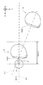
図10は、ゴルフボール2を打撃する直前のゴルフクラブヘッド16を平面視した状態を示す平面図、図11は左右進入角θの定義を説明する模式図、図12は打撃時フェース角φを説明する模式図である。
なお、図11、図12において符号1610は、ゴルフクラブヘッド16のフェース面1602の中心位置を示す。
図10、図11に示すように、ゴルフボール2の中心と目標とを結ぶ目標線を前記の平面に投影した直線を基準線L0とする。
ここで、基準線L0はX軸と平行するものとし、したがって、前記の平面はX軸およびY軸と平行しZ軸と直交する。
ゴルフボール2を打撃する直前におけるゴルフクラブヘッド16の移動軌跡の接線を水平面と平行な平面に投影した直線を第1の直線L1とする。
左右進入角θは基準線L0と第1の直線L1がなす角度である。
図12に示すように、ゴルフボール2を打撃する直前におけるゴルフクラブヘッド16のフェース面1602の中心点を通る法線を前記の平面に投影した直線を第2の直線L2とする。
打撃時フェース角φは基準線L0と第2の直線L2がなす角度である。
The
FIG. 10 is a plan view showing a state in which the
11 and 12,
As shown in FIGS. 10 and 11, a straight line obtained by projecting a target line connecting the center of the
Here, it is assumed that the reference line L0 is parallel to the X axis, and thus the plane is parallel to the X axis and the Y axis and orthogonal to the Z axis.
A straight line obtained by projecting a tangent of the movement locus of the
The left / right approach angle θ is an angle formed by the reference line L0 and the first straight line L1.
As shown in FIG. 12, a straight line obtained by projecting a normal line passing through the center point of the
The hit face angle φ is an angle formed by the reference line L0 and the second straight line L2.
すなわち、解析部56は、算出部56で算出された3次元形状モデルの位置および向きの時系列データから、基準線L0と第1の直線L1とがなす角度を左右進入角θとして求めると共に、基準線L0と第2の直線L2とがなす角度を打撃時フェース角φとして求める。
このことについて具体的に説明する。
ゴルフボール2の打撃直後、ゴルフクラブヘッド16の移動速度は低下するので、一定時間間隔のフェース面1602の中心位置1610の移動を表す位置座標の時系列データにおいて、打撃直前と打撃直後の位置座標の移動距離はそれ以前の各時点での移動距離に比べて急激に短くなる。
このことを利用して、図11に示すように、ゴルフクラブヘッド16の位置座標を示す時系列データから、ゴルフボール2の打撃直前のゴルフクラブヘッド16の位置座標(中心位置1610)と、時系列データにおいて1つ前の位置座標とを特定することができる。
そして、この2つの位置座標を結ぶ直線L1がゴルフクラブヘッド16の移動軌跡の接線となる。
また、同様に上記のことを利用して、図12に示すように、ゴルフクラブヘッド16の向きを示す法線を示す時系列データから、ゴルフボール2を打撃する直前におけるゴルフクラブヘッド16のフェース面1602の法線を特定することができる。
解析部56は、このようにしてゴルフボール2を打撃する直前におけるゴルフクラブヘッド16の移動軌跡の接線とフェース面1602の法線とを特定することにより、前記のような手順で左右進入角θおよび打撃時フェース角φを求める。
That is, the
This will be specifically described.
Immediately after the
By utilizing this fact, as shown in FIG. 11, from the time-series data indicating the position coordinates of the
A straight line L1 connecting the two position coordinates is a tangent to the movement locus of the
Similarly, using the above, as shown in FIG. 12, the face of the
The
ゴルフクラブヘッド16のヘッドスピードは通常30〜50m/秒であるため、カメラ26による撮影間隔である2000分の1秒の時間間隔δで、ゴルフクラブヘッド16は、15mm〜25mm移動する。
したがって、ゴルフボール2の中心からX軸方向に沿ってゴルフボール2の打ち出し方向と反対方向で50mm手前の範囲において2つの時系列データ(位置座標データ)が特定される。
そのため、本実施の形態では、ゴルフボール2の中心から手前50mmの範囲における時系列データに基づいて左右進入角θおよび打撃時フェース角φが求められることになる。
なお、カメラ26による撮影間隔は1/2000秒に限定されるものではなく、得られた時系列データに基づいて左右進入角θおよび打撃時フェース角φを求めることができればよいのであり、例えば、撮影間隔を1/10000秒〜1/500秒の間で設定するなど任意である。
また、本実施の形態では、左右進入角θは、基準線L0を中心としてゴルファの反対側を正(プラス)の角度とし、ゴルファ側を負(マイナス)の角度とする。
また、打撃時フェース角φについても同様に、基準線L0を中心としてゴルファの反対側を正(プラス)の角度とし、ゴルファ側を負(マイナス)の角度とする。
Since the head speed of the
Therefore, two time-series data (positional coordinate data) are specified in a
Therefore, in the present embodiment, the left / right approach angle θ and the hitting face angle φ are obtained based on time-series data in a range of 50 mm from the center of the
Note that the shooting interval by the
Further, in the present embodiment, the left and right approach angle θ is a positive (plus) angle on the opposite side of the golfer around the reference line L0, and a negative (minus) angle on the golfer side.
Similarly, with respect to the hitting face angle φ, the opposite side of the golfer around the reference line L0 is a positive (plus) angle, and the golfer side is a negative (minus) angle.
推定部90は、左右進入角θと打撃時フェース角φとの測定値から、ゴルフボールの左右打ち出し角αおよびサイドスピン量Ssを推定するものである。
左右打ち出し角αは、ゴルファによりスウィングされたゴルフクラブのゴルフクラブヘッド16によって打撃されて打ち出された直後のゴルフボールの軌跡を平面に投影した線と基準線L0とがなす角度をいう。
左右打ち出し角αの正負は、基準線L0を中心としてゴルファの反対側を正の角度とし、ゴルファ側を負の角度とする。
図13は、横軸(X軸)に左右進入角θ、縦軸(Y軸)に打撃時フェース角φをそれぞれ0度から正負に0.5度単位で表示し、各座標点に左右打ち出し角αのデータを配置した場合の模式図である。
なお、データの具体的な数値は省略している。また、左右進入角θ、打撃時フェース角φの角度が0.5度単位で変化する場合について例示するが、角度の単位を0.5度よりも小さくするなど任意である。
ハッチング部分は左右打ち出し角αが0度に相当しており、ハッチング部分よりも上方の範囲は左右打ち出し角αが正(右方向)であり、ハッチング部分よりも下方の範囲は左右打ち出し角αが負(左方向)である(ゴルファが右利きの場合)。
The
The left and right launch angle α is an angle formed by a reference line L0 and a line formed by projecting a trajectory of a golf ball immediately after being hit by the
With respect to the right and left launch angle α, the opposite side of the golfer around the reference line L0 is a positive angle, and the golfer side is a negative angle.
In FIG. 13, the horizontal axis (X-axis) displays the left and right approach angle θ, and the vertical axis (Y-axis) displays the hitting face angle φ from 0 degree to positive and negative in 0.5 degree units. It is a schematic diagram at the time of arrange | positioning the data of angle | corner (alpha).
Note that specific numerical values of the data are omitted. Further, the case where the left and right approach angles θ and the hitting face angle φ are changed in units of 0.5 degrees is exemplified, but the angle unit may be arbitrarily set to be smaller than 0.5 degrees.
The hatched portion has a left and right launch angle α corresponding to 0 degree, the range above the hatched portion is positive (rightward), and the range below the hatched portion has a left and right launch angle α. Negative (left direction) (when golfer is right-handed).
サイドスピン量Ssは、ゴルファによりスウィングされたゴルフクラブのゴルフクラブヘッド16によって打撃されて打ち出された直後のゴルフボール2のゴルフボール2の中心を通る鉛直線回りのスピン量をいう。
サイドスピン量Ssの正負は、平面視時計回りを正とし、反時計回りを負とする。
推定部90は、第1の回帰式に基いて左右進入角θと打撃時フェース角φとの測定値から左右打ち出し角αを特定すると共に、第2の回帰式に基いて左右進入角θと打撃時フェース角φとの測定値からサイドスピン量Ssを特定するものである。
図14は、横軸(X軸)に左右進入角θ、縦軸(Y軸)に打撃時フェース角φをそれぞれ0度から正負に0.5度単位で表示し、各座標点にサイドスピン量Ssのデータを配置した場合の模式図である。
なお、データの具体的な数値は省略している。また、図13と同様に、角度の単位を0.5度よりも小さくするなど任意である。
ハッチング部分がサイドスピン量Ssがゼロに相当しており、ハッチング部分よりも上方の範囲はサイドスピン量Ssが正(スライス傾向)であり、ハッチング部分よりも下方の範囲はサイドスピン量Ssが負(フック傾向)である(ゴルファが右利きの場合)。
The side spin amount Ss is a spin amount around a vertical line passing through the center of the
The positive or negative side spin amount Ss is positive when viewed clockwise in plan view and negative when counterclockwise.
The
In FIG. 14, the horizontal axis (X-axis) displays the left and right approach angle θ, and the vertical axis (Y-axis) displays the hitting face angle φ from 0 degree to positive and negative in 0.5 degree units. It is a schematic diagram at the time of arrange | positioning the data of quantity Ss.
Note that specific numerical values of the data are omitted. Further, similarly to FIG. 13, the unit of the angle is arbitrary, for example, smaller than 0.5 degrees.
The hatched portion corresponds to zero side spin amount Ss, the range above the hatched portion has a positive side spin amount Ss (slice tendency), and the range below the hatched portion has a negative side spin amount Ss. (Hook tendency) (when golfer is right-handed).
第1の回帰式および第2の回帰式は、以下のようにして作成される。
実際にゴルファによりスウィングされたゴルフクラブのゴルフクラブヘッド16の左右進入角θと打撃時フェース角φとを上述のような手順により実測する。
そして、その際、ゴルフクラブヘッド16によって打撃されて打ち出された直後のゴルフボール2の左右打ち出し角αとサイドスピン量Ssとを基準計測器により測定する。このような基準計測器として、例えば、特許第4104384号に開示されているような従来公知の様々な測定装置が使用可能である。
このような測定を複数のゴルファにより複数回行なうことにより、左右進入角θ、打撃時フェース角φ、左右打ち出し角α、サイドスピン量Ssのデータを取得する。
そして、左右進入角θと打撃時フェース角φと左右打ち出し角αとの実測値に基いて左右進入角θと打撃時フェース角φとから左右打ち出し角αを特定する第1の回帰式を作成する。
また、左右進入角θと打撃時フェース角φとサイドスピン量Ssとの実測値に基いて左右進入角θと打撃時フェース角φとからサイドスピン量Ssを特定する第2の回帰式を作成する。
なお、第1の回帰式は例えば以下のように表現される。
左右打ち出し角α=左右進入角θ×係数a1+打撃時フェース角φ×係数b1+定数c1
また、第2の回帰式は例えば以下のように表現される。
サイドスピン量Ss=左右進入角θ×係数a2+打撃時フェース角φ×係数b2+定数c2
また、上記の係数a1、a2、b1、b2、定数c1、c2は、クラブヘッドのバルジ、ロールの有無(大小)、慣性モーメントの大きさによって異なる。
なお、第1、第2の回帰式の形態は例示されたものに限定されず、従来公知の様々な回帰式が採用可能である。
推定部90は、このような第1の回帰式および第2の回帰式を保持している。また、推定部90は、第1の回帰式および第2の回帰式に代えて、左右進入角θと打撃時フェース角φとから左右打ち出し角αを特定する第1のマップ、左右進入角θと打撃時フェース角φとからサイドスピン量Ssを特定する第2のマップを備えていてもよい。
The first regression equation and the second regression equation are created as follows.
The left and right approach angle θ of the
At that time, the left and right launch angle α and the side spin amount Ss of the
By performing such measurement a plurality of times by a plurality of golfers, data of the left and right approach angle θ, the hitting face angle φ, the left and right launch angle α, and the side spin amount Ss are acquired.
Then, based on the measured values of the left and right approach angle θ, the hitting face angle φ, and the left and right launch angle α, a first regression equation is created that specifies the left and right launch angle α from the left and right approach angle θ and the hitting face angle φ. To do.
Also, a second regression equation is created that specifies the side spin amount Ss from the left and right approach angle θ and the hitting face angle φ based on the measured values of the left and right approaching angle θ, the hitting face angle φ, and the side spin rate Ss. To do.
The first regression equation is expressed as follows, for example.
Left and right launch angle α = left and right approach angle θ × coefficient a1 + striking face angle φ × coefficient b1 + constant c1
The second regression equation is expressed as follows, for example.
Side spin amount Ss = left and right approach angle θ × coefficient a 2 + hit face angle φ ×
The coefficients a1, a2, b1, b2 and the constants c1, c2 are different depending on the bulge of the club head, the presence / absence (large or small) of roll, and the magnitude of the moment of inertia.
The forms of the first and second regression equations are not limited to those illustrated, and various conventionally known regression equations can be employed.
The
シミュレーション部92は、推定された左右打ち出し角αおよびサイドスピン量Ssと、ゴルフボール2のボール初速V0と、ゴルフボール2の上下打ち出し角βとに基いてゴルフボール2の移動軌跡(弾道)をシミュレーションして基準線L0から着弾地点までの距離であるシフト量ΔSを算出するものである。
上下打ち出し角βは、ゴルファによりスウィングされたゴルフクラブのゴルフクラブヘッド16によって打撃されて打ち出された直後のゴルフボール2の軌跡を基準線L0を含む鉛直面に投影した線と基準線L0とがなす角度をいう。
なお、ボール初速V0と上下打ち出し角βとしてゴルファの属性に対応して予め定められた固定値を用いることができる。ゴルファの属性とは、男子プロゴルフ、男子アマチュアゴルファ、女子プロゴルファ、女子アマチュアゴルファといった体格(筋力)や技量の高低で分類されるものである。
また、シミュレーションに際しては、ゴルファによりスウィングされたゴルフクラブのゴルフクラブヘッド16によって打撃されて打ち出された直後のゴルフボール2のバックスピン量Sbを考慮してもよく、バックスピン量Sbを考慮することでシミュレーションの精度を高める上で有利となる。
なお、ボール初速V0、上下打ち出し角β、バックスピン量Sbを固定値とせず、前記の基準測定器によって測定されたボール初速V0、上下打ち出し角β、バックスピン量Sbの実測値を用いてシミュレーションを行ってもよく、それら実測値を用いることでシミュレーションの精度を高める上で有利となる。
The
The vertical launch angle β is defined by a line obtained by projecting the trajectory of the
Note that fixed values predetermined in accordance with the attributes of the golfer can be used as the initial ball velocity V0 and the vertical launch angle β. The attributes of golfers are classified according to physique (muscular strength) and skill level such as male professional golf, male amateur golfer, female professional golfer, and female amateur golfer.
In the simulation, the backspin amount Sb of the
Note that the initial ball speed V0, the vertical launch angle β, and the backspin amount Sb are not fixed values, and simulation is performed using the measured values of the initial ball velocity V0, the vertical launch angle β, and the backspin amount Sb measured by the reference measuring device. It is advantageous to increase the accuracy of the simulation by using these measured values.
分類マップ作成部94は、左右進入角θと打撃時フェース角φとシフト量ΔSとからなるデータを蓄積し、蓄積されたデータに基いて、左右進入角θを示すX軸と、X軸に直交し打撃時フェース角φを示すY軸と、それらX軸、Y軸の交点を左右進入角θおよび打撃時フェース角φのゼロ度とした2次元座標上に、左右進入角θと打撃時フェース角φとシフト量ΔSとに基いて特定される球筋の傾向に応じて境界分けされた複数のエリアを規定した分類マップD3を作成するものである。
分類マップD3は記憶部64に格納されている。なお、分類マップD3をどこに設けるかは任意である。
The classification
The classification map D3 is stored in the storage unit 64. Note that where the classification map D3 is provided is arbitrary.
左右進入角θおよび打撃時フェース角φと、ゴルフボール2の球筋との関係について説明する。
左右進入角θが負の値でその絶対値が大きくなるほど、ゴルフクラブヘッド16の軌道はアウトサイドイン傾向を示すため、打ち出されたゴルフボール2の打ち出し方向は左方向となる。
左右進入角θが正の値でその絶対値が大きくなるほどゴルフクラブヘッド16の軌道はインサイドアウト傾向を示すため、打ち出されたゴルフボール2の打ち出し方向は右方向となる。
打撃時フェース角φが負の値でその絶対値が大きくなるほど打ち出されたゴルフボール2は、上方から見て反時計方向回りのサイドスピンが掛かりやすくなる。
打撃時フェース角φが正の値でその絶対値が大きくなるほど打ち出されたゴルフボール2は、上方から見て時計方向回りのサイドスピンが掛かりやすくなる。
このように左右進入角θと打撃時フェース角φとの組み合わせによって、ゴルフボール2の打ち出し方向の左右とサイドスピンの掛かりやすさとが影響を受けることにより、打ち出されたゴルフボール2はスライス傾向、フェード傾向、ストレート傾向、ドロー傾向、フック傾向の球筋となる。
ここで、スライス傾向とは、右利きのゴルファがゴルフボール2を打ったときに、ゴルフボール2が右側に曲がるものをいう。左利きのゴルファの場合には左側に曲がるものをいう。
また、フェード傾向とは、コントロールされたスライス傾向をいい、目標線に対して左に打ち出されたゴルフボール2の着弾位置がほぼ目標線に戻ってくるものをいう。
また、フック傾向とは、右利きのゴルファがゴルフボール2を打ったときに、ゴルフボール2が左側に曲がるものをいう。左利きのゴルファの場合には右側に曲がるものをいう。
また、ドロー傾向とは、コントロールされたフック傾向をいい、目標線に対して右に打ち出されたゴルフボール2の着弾位置がほぼ目標線に戻ってくるものをいう。
また、ストレート傾向とは、打ち出されたゴルフボール2が曲がることなく直進していくものをいう。
このように、ゴルフボール2を打撃する直前のゴルフクラブヘッド16の挙動に応じてゴルフボール2の球筋(軌跡)は様々に異なっている。
さらに、シミュレーションにより求められたシフト量ΔSが小さいほど、着弾地点が基準線L0に近く好ましい球筋であり、シフト量ΔSが大きいほど、着弾地点が基準線L0から遠く好ましくない球筋であると評価される。
The relationship between the left / right approach angle θ and the hitting face angle φ and the ball of the
As the left / right approach angle θ becomes negative and the absolute value thereof increases, the trajectory of the
As the left and right approach angle θ becomes a positive value and the absolute value thereof increases, the trajectory of the
The
The
Thus, the combination of the left / right approach angle θ and the hitting face angle φ affects the left / right of the launch direction of the
Here, the slicing tendency means that when a right-handed golfer hits the
The fade tendency refers to a controlled slicing tendency, in which the landing position of the
The hook tendency means that when a right-handed golfer hits the
The draw tendency refers to a controlled hook tendency, in which the landing position of the
Further, the straight tendency means that the hit
As described above, the ball streak (trajectory) of the
Furthermore, it is evaluated that the smaller the shift amount ΔS obtained by the simulation, the closer the landing point is to the reference line L0, and the more preferable the ball point, and the larger the shift amount ΔS, the farther the landing point is from the reference line L0, the less favorable the ball point. The
分類マップD3は、左右進入角θをX座標の値とし、打撃時フェース角φをY座標の値として2次元座標上に示し、かつ、2次元座標で示される平面をゴルフボール2の球筋に対応する複数のエリア(領域)に区分して関連付けたものである。
言い換えると、分類マップD3は、左右進入角θを示すX軸と、X軸に直交し打撃時フェース角φを示すY軸とを備え、それらX軸、Y軸の交点を左右進入角θおよび打撃時フェース角φのゼロ度とした2次元座標軸で示される平面をゴルフボール2の球筋に対応する複数のエリア(領域)に区分して関連付けたものである。
複数のエリアは、左右進入角θと打撃時フェース角φとシフト量ΔSとに基いて特定される球筋の傾向に応じて境界分けされている。
分類部58によるゴルフクラブのスウィングの特定は分類マップD3を用いてなされる。
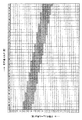
図15は、分類マップD3の構成を説明する模式図であり、横軸(X軸)に左右進入角θ、縦軸(Y軸)に打撃時フェース角φをそれぞれ0度から正負に0.5度単位で表示し、各座標点にシフト量ΔSのデータを配置している。図中、データの具体的な数値は省略している。なお、以下では、ゴルファが右利きである場合を前提としており、左利きの場合は正負が反対となる。
In the classification map D3, the left and right approach angle θ is set as an X-coordinate value, the hitting face angle φ is set as a Y-coordinate value on a two-dimensional coordinate, and a plane indicated by the two-dimensional coordinate is set as a spherical muscle of the
In other words, the classification map D3 includes an X axis that indicates the left and right approach angle θ and a Y axis that is orthogonal to the X axis and indicates the hitting face angle φ, and the intersection of the X axis and the Y axis is the left and right approach angles θ and A plane indicated by a two-dimensional coordinate axis having a face angle φ of 0 when hit is divided into a plurality of areas (regions) corresponding to the spherical muscles of the
The plurality of areas are demarcated according to the tendency of the spherical muscle specified based on the left / right approach angle θ, the hitting face angle φ, and the shift amount ΔS.
The golf club swing is identified by the
FIG. 15 is a schematic diagram for explaining the configuration of the classification map D3. The horizontal axis (X-axis) has a left / right approach angle θ, and the vertical axis (Y-axis) has a striking face angle φ from 0 degrees to 0. The data is displayed in units of 5 degrees, and shift amount ΔS data is arranged at each coordinate point. In the figure, specific numerical values of the data are omitted. In the following, it is assumed that the golfer is right-handed, and in the case of left-handed, the sign is opposite.
具体的に説明すると、分類マップD3は、図15に示すように、左右進入角θと打撃時フェース角φとの組み合わせに対応して、スライスエリアA1、フェードエリアA2、ストレートエリアA3、ドローエリアA4、フックエリアA5といったゴルフボール2の球筋に対応する5つのエリアがそれぞれ関連付けられている。
スライスエリアA1は球筋がスライス傾向となるエリアであり、フェードエリアA2は球筋がフェード傾向となるエリアであり、ストレートエリアA3は球筋がストレート傾向となるエリアであり、ドローエリアA4は球筋がドロー傾向となるエリアであり、フックエリアA5は球筋がフック傾向となるエリアである。
言い換えると、左右進入角θと打撃時フェース角φとの組み合わせがエリアA1〜A5の何れに該当するかによってゴルフクラブのスウィングのタイプが、スライスタイプ、フェードタイプ、ストレートタイプ、ドロータイプ、フックタイプの何れかのタイプに特定される。
すなわち、分類部58は、解析部58で得られた左右進入角θと打撃時フェース角φとに基づいて、ゴルフスウィングが分類マップD3に格納されている複数のタイプの何れのタイプに該当するかを特定する。
More specifically, as shown in FIG. 15, the classification map D3 corresponds to the combination of the left and right approach angle θ and the hitting face angle φ, the slice area A1, the fade area A2, the straight area A3, and the draw area. Five areas corresponding to the ball of the
The slice area A1 is an area where the spherical muscle tends to slice, the fade area A2 is an area where the spherical muscle tends to fade, the straight area A3 is an area where the spherical muscle tends to be straight, and the draw area A4 is a trend where the spherical muscle tends to draw. The hook area A5 is an area where the spherical muscle tends to hook.
In other words, depending on whether the combination of the left and right approach angle θ and the hitting face angle φ corresponds to any of the areas A1 to A5, the golf club swing type is slice type, fade type, straight type, draw type, hook type Specific to any type.
That is, the
なお、分類マップD3上におけるスライスエリアA1、フェードエリアA2、ストレートエリアA3、ドローエリアA4、フックエリアA5は、次のようにして決定する。
図16は、各エリア、境界線を説明する模式図である。
図16は、図15と同様に、横軸(X軸)に左右進入角θ、縦軸(Y軸)に打撃時フェース角φをそれぞれ0度から正負に0.5度単位で表示し、各座標点にシフト量ΔSのデータを配置している。図中、データの具体的な数値は省略している。
符号LAで示すハッチング部分が、第1の境界線であり、着弾地点が基準線L0上に合致しており、シフト量ΔSがゼロとなっている。
さらに、符号M1で示すハッチング部分は、着弾地点が基準線L0に対して右側に位置し、シフト量ΔSが0より大きく10ヤード以下の範囲を示す。
符号M2で示すハッチング部分は、着弾地点が基準線L0に対して左側に位置し、シフト量ΔSが0以上10ヤード以下の範囲を示す。
符号LBで示す部分が、第2の境界線であり、サイドスピン量Ssが0rpm(ストレートエリアA3)に相当している。第2の境界線LBは、X軸およびY軸で示される2次元座標上において第1の境界線LAと交差し、かつ、第1の境界線LAよりも大きな正の傾きの傾斜を有している。
符号M3で示す部分が、サイドスピン量Ssが正の値であり0rpm以上500rpm以下の範囲を示す。
符号M4で示す部分が、サイドスピン量Ssが負の値であり0rpm以上500rpm以下の範囲を示す。
なお、シフト量ΔSの上限値、下限値、サイドスピン量Ssの上限値、下限値は、上記の数値に限定されるものではなく、任意に設定される。
The slice area A1, fade area A2, straight area A3, draw area A4, and hook area A5 on the classification map D3 are determined as follows.
FIG. 16 is a schematic diagram illustrating each area and boundary line.
FIG. 16 shows the horizontal approach angle θ on the horizontal axis (X axis) and the face angle φ at impact on the vertical axis (Y axis) in units of 0.5 degrees from 0 degree to positive and negative, respectively, as in FIG. Data of the shift amount ΔS is arranged at each coordinate point. In the figure, specific numerical values of the data are omitted.
The hatched portion indicated by the symbol LA is the first boundary line, the landing point matches the reference line L0, and the shift amount ΔS is zero.
Further, the hatched portion indicated by reference numeral M1 indicates a range where the landing point is located on the right side with respect to the reference line L0 and the shift amount ΔS is greater than 0 and equal to or less than 10 yards.
The hatched portion indicated by reference numeral M2 indicates a range where the landing point is located on the left side with respect to the reference line L0 and the shift amount ΔS is 0 or more and 10 yards or less.
A portion indicated by a symbol LB is the second boundary line, and the side spin amount Ss corresponds to 0 rpm (straight area A3). The second boundary line LB intersects with the first boundary line LA on the two-dimensional coordinates indicated by the X axis and the Y axis, and has a larger positive slope than the first boundary line LA. ing.
A portion indicated by a symbol M3 indicates a range in which the side spin amount Ss is a positive value and is from 0 rpm to 500 rpm.
A portion indicated by a symbol M4 indicates a range in which the side spin amount Ss is a negative value and is from 0 rpm to 500 rpm.
The upper limit value and lower limit value of the shift amount ΔS and the upper limit value and lower limit value of the side spin amount Ss are not limited to the above numerical values, and are arbitrarily set.
第1の境界線LAと第2の境界線LBで挟まれた2つの領域のうち、X軸およびY軸の正方向寄りに位置する領域がドローエリアA4である。
第1の境界線LAと第2の境界線LBで挟まれた2つの領域のうち、X軸およびY軸の負方向寄りに位置する領域がフェードエリアA2である。
ドローエリアA4およびフェード領域A2よりもY軸の正方向側に位置する領域がスライスエリアA1である。
ドローエリアA4およびフェード領域A2よりもY軸の負方向側に位置する領域がフックエリアA5である。
第2の境界線LBの部分がストレートエリアA3である。
Of the two regions sandwiched between the first boundary line LA and the second boundary line LB, the region located closer to the positive direction of the X axis and the Y axis is the draw area A4.
Of the two regions sandwiched between the first boundary line LA and the second boundary line LB, the region located closer to the negative direction of the X axis and the Y axis is the fade area A2.
A region located on the positive side of the Y axis from the draw area A4 and the fade region A2 is the slice area A1.
The area located on the negative direction side of the Y axis from the draw area A4 and the fade area A2 is the hook area A5.
The portion of the second boundary line LB is the straight area A3.
本実施の形態では、球筋を以上の5種類に分類することに加えて、球筋をシフト量ΔSによって評価している。
まず、シフト量ΔSが0ヤード±10ヤードの範囲を良い球筋とする。
したがって、図16において、0ヤード±10ヤードの範囲内に合致する領域、すなわち、符号M1、LA、M2で示す領域が良い球筋として評価される。
In this embodiment, in addition to classifying the ball muscles into the above five types, the ball muscles are evaluated by the shift amount ΔS.
First, the range of the shift amount ΔS of 0 yard ± 10 yards is defined as a good ball line.
Therefore, in FIG. 16, a region that falls within the range of 0 yard ± 10 yards, that is, a region indicated by symbols M1, LA, and M2 is evaluated as a good ball.
また、シフト量ΔSが±10ヤード以内であっても、サイドスピン量Ssが大きくしたがってゴルフボール2の移動軌跡が大きく湾曲している場合は、飛距離が低下することから、図16において、符号M1、LA、M2で示す領域で、かつ、符号M3、M4で示す領域、すなわちシフト量ΔSが±10ヤード以内であって、サイドスピン量Ssが0rpm以上500rpm以下の範囲をより良い球筋として評価する。
In addition, even if the shift amount ΔS is within ± 10 yards, the flying distance is reduced when the side spin amount Ss is large and the movement locus of the
また、シフト量ΔSが±10ヤード以内で、スピン量が500rpm以下であっても、平面視した際のゴルフボール2の移動軌跡がいったん基準線L0の右側(左側)に凸状を描くように曲がって基準線L0を超えて反対側の左側(右側)の地点に着弾した場合は、基準線L0を超えないで着弾した場合に比較して、ゴルフ競技としての技術的な評価が低くなる。
そのため、平面視した際のゴルフボール2の移動軌跡がいったん基準線L0の右側(左側)に凸状を描くように曲がって基準線L0を超えることなく同じ右側(左側)の地点に着弾した場合は球筋の評価を良いものとする。
図16において、符号N1、N2で示す領域は、シフト量ΔSが0ヤード±10ヤードであり、かつ、サイドスピン量Ssが0rpm以上500rpm以下の範囲であるが、平面視した際のゴルフボール2の移動軌跡が基準線L0を超えて着弾する球筋に対応している。
したがって、図16において符号M1、L1、M2で示す領域で、かつ、符号M3、M4で示す領域のうち、基準線L0を超える球筋となる領域N1、N2を除いた残りの領域O、P(太線で囲まれた領域)を最もよい球筋として評価する。
本実施の形態では、フェードエリアA2、ドローエリアA4、ストレートエリアA3のうちでも符号O、Pで示される領域が最も良い球筋であるものとして評価するものとする。
なお、以下に示す3種類の評価のどれを採用するかは任意であるが、1)、2)、3)の順番で良いと評価される球筋の、面積が分類マップD3上で占める面積が小さくなり、評価がより厳しくなる。
1)符号M1、L1、M2で示す領域(サイドスピン量Ssが0rpm以上500rpm以下の範囲)を良い球筋として評価する。
2)符号M1、L1、M2で示す領域で、かつ、符号M3、M4で示す領域(シフト量ΔSが±10ヤード以内であって、サイドスピン量Ssが0rpm以上500rpm以下の範囲)を良い球筋として評価する。
3)符号M1、L1、M2で示す領域で、かつ、符号M3、M4で示す領域のうち、基準線L0を超える球筋となる領域N1、N2を除いた残りの領域O、Pを良い球筋として評価する。
Further, even when the shift amount ΔS is within ± 10 yards and the spin amount is 500 rpm or less, the movement trajectory of the
Therefore, when the movement trajectory of the
In FIG. 16, the regions indicated by reference signs N <b> 1 and N <b> 2 have a shift amount ΔS of 0 yard ± 10 yards and a side spin amount Ss of 0 rpm to 500 rpm. Corresponds to the ball muscle that landed beyond the reference line L0.
Therefore, in the areas indicated by reference numerals M1, L1, and M2 in FIG. 16 and the areas indicated by reference numerals M3 and M4, the remaining areas O and P (except for the areas N1 and N2 that are spherical streaks that exceed the reference line L0 are included. The area surrounded by the bold line) is evaluated as the best bulb.
In the present embodiment, it is assumed that the area indicated by the symbols O and P among the fade area A2, the draw area A4, and the straight area A3 is evaluated as the best ball line.
It should be noted that which of the following three types of evaluation is adopted is arbitrary, but the area occupied on the classification map D3 by the area of the ball muscle evaluated as good in the order of 1), 2) and 3) is acceptable. It becomes smaller and evaluation becomes more severe.
1) Evaluate the region indicated by the symbols M1, L1, and M2 (side spin amount Ss in the range of 0 rpm to 500 rpm) as a good ball.
2) Spherical muscles in the areas indicated by the symbols M1, L1, and M2 and the regions indicated by the symbols M3 and M4 (the range in which the shift amount ΔS is within ± 10 yards and the side spin amount Ss is 0 rpm or more and 500 rpm or less) Evaluate as
3) The remaining areas O and P excluding the areas N1 and N2, which are the areas indicated by the symbols M1, L1, and M2, and the areas indicated by the symbols M3 and M4 and that exceed the reference line L0 are used as good spherical muscles. evaluate.
図15について説明すると、フェードエリアA2、ドローエリアA4、ストレートエリアA3のうち球筋が良いとして評価される部分にハッチングを施している。なお、図面の簡略化を図るためストレートエリアA3は直線で示している。
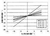
なお、第1の境界線LA、第2の境界線LB、各エリアA2、A3、A4は、ゴルフクラブヘッド16の番手、ゴルファの属性などによって変化する。このことについて図17〜図22を参照して説明する。図17〜図22において第1の境界線LAの図示は省略している。
図17〜図19は、ゴルフクラブがドライバーである場合の分類マップD3の例であり、図18は男子プロゴルファー(初速V0:70m/s、上下打ち出し角β:13度、バックスピン量Sb:3000rpm)、図19は男子アマチュア(初速V0:60m/s、上下打ち出し角β:15度、バックスピン量Sb:2500rpm)、図20は女子アマチュア(初速V0:45m/s、上下打ち出し角β:17度、バックスピン量Sb:2200rpm)を示す。
Referring to FIG. 15, hatching is applied to a portion that is evaluated as having good spherical muscles in the fade area A2, the draw area A4, and the straight area A3. In order to simplify the drawing, the straight area A3 is shown by a straight line.
Note that the first boundary line LA, the second boundary line LB, and the areas A2, A3, and A4 vary depending on the
FIGS. 17 to 19 are examples of a classification map D3 when the golf club is a driver. FIG. 18 shows a male professional golfer (initial speed V0: 70 m / s, vertical launch angle β: 13 degrees, backspin amount Sb: 3000 rpm. 19 is a male amateur (initial speed V0: 60 m / s, vertical launch angle β: 15 degrees, backspin amount Sb: 2500 rpm), and FIG. 20 is a female amateur (initial speed V0: 45 m / s, vertical launch angle β: 17). Degree, backspin amount Sb: 2200 rpm).
図20〜図22は、ゴルフクラブが7番アイアンである場合の分類マップD3の例であり、図20は男子プロゴルファー(初速V0:53m/s、上下打ち出し角β:18度、バックスピン量Sb:6000rpm)、図21は男子アマチュア(初速V0:46m/s、上下打ち出し角β:19度、バックスピン量Sb:5000rpm)、図22は女子アマチュア(初速V0:35m/s、上下打ち出し角β:20度、バックスピン量Sb:4000rpm)を示す。
図17〜図22に示すように、ドライバーと7番アイアンとでは、各エリアの形状や面積が異なっていることがわかる。
また、ボール初速V0が速くなるほど、良い球筋として評価されるエリアの面積が狭くなっており、良い球筋を得るために必要な左右進入角θと打撃時フェース角φの範囲が狭くなる傾向であることがわかる。
20 to 22 are examples of the classification map D3 when the golf club is a 7 iron. FIG. 20 shows a male professional golfer (initial speed V0: 53 m / s, vertical launch angle β: 18 degrees, back spin amount Sb. 21 is a male amateur (initial speed V0: 46 m / s, vertical launch angle β: 19 degrees, backspin amount Sb: 5000 rpm), FIG. 22 is a female amateur (initial speed V0: 35 m / s, vertical launch angle β). : 20 degrees, backspin amount Sb: 4000 rpm).
As shown in FIGS. 17-22, it turns out that the shape and area of each area differ in a driver and the 7th iron.
In addition, as the ball initial velocity V0 increases, the area of the area evaluated as a good spherical muscle is narrowed, and the range of the left and right approach angle θ and the hitting face angle φ required to obtain a good spherical muscle tends to be narrowed. I understand that.
この他にも、選定装置10に起因する原因によって、分類マップD3上における各エリアの位置や面積は変化するため、分類マップD3は選定装置10に応じて作成されることになる。
また、厳密に言うと、第1、第2の境界線LA、LBの傾きは、ゴルフクラブヘッド16のフェース面1602のバルジとゴルフクラブヘッド16の慣性モーメントとの影響によって若干変化する。
In addition, since the position and area of each area on the classification map D3 change due to the cause caused by the
Strictly speaking, the inclinations of the first and second boundary lines LA and LB slightly change due to the influence of the bulge of the
図23は、簡略化した分類マップD3の表示例を示す図である。
図23では、各エリアを視覚的に単純化して表示する都合上、フェードエリアA2、ドローエリアA4を楕円形状で示し、フェードエリアA2とドローエリアA4との一部が重なり、フェードエリアA2とドローエリアA4とが第1、第2の境界線LA、LBの外側にはみ出しているが、厳密には、前述した図15に示すように、フェードエリアA2、ドローエリアA4、第1、第2の境界線LA、LBは互いに重なり合うことはない。
また、図23の上部には、基準線L0に対するゴルフクラブヘッド16の移動方向を示す矢印F1が示されており、左右進入角θを模式的に示している。
また、図23の左側には、ゴルフクラブヘッド16のフェース面1602の向きを示す矢印F2が示されおり、打撃時フェース角φを模式的に示している。
また、前述した3種類の評価のどれを採用するかに応じて、フェードエリアA2、ドローエリアA4、ストレートエリアA3の面積が増減することになる。
FIG. 23 is a diagram illustrating a display example of a simplified classification map D3.
In FIG. 23, the fade area A2 and the draw area A4 are shown in an oval shape for the convenience of visually simplifying and displaying each area, and the fade area A2 and the draw area A4 partially overlap, so Although the area A4 protrudes outside the first and second boundary lines LA and LB, strictly speaking, as shown in FIG. 15 described above, the fade area A2, the draw area A4, the first and second areas The boundary lines LA and LB do not overlap each other.
In addition, an arrow F1 indicating the moving direction of the
Further, on the left side of FIG. 23, an arrow F2 indicating the direction of the
Further, the areas of the fade area A2, the draw area A4, and the straight area A3 increase or decrease depending on which of the three types of evaluation described above is adopted.
分類部58は、左右進入角θと打撃時フェース角φとに基づいてゴルフクラブのスウィングが予め定められた複数のタイプのうちの何れのタイプに該当するかを、分類マップD3を用いて特定するものである。
The
選定部60は、分類部58によって特定されたタイプに応じて最適なゴルフクラブを選定するものである。
本実施の形態では、ゴルフクラブのスウィングのタイプと該タイプに最適なゴルフクラブとが関連付けられた選定情報D4が予め用意されており、具体的には、選定情報D4は記憶部64に格納されている。なお、選定情報D4をどこに格納するかは任意である。
選定情報D4はゴルフクラブのスウィングのタイプと該タイプに最適なゴルフクラブとが関連付けられた情報である。
選定情報D4は、例えば、ゴルフクラブのスウィングのタイプと該タイプに最適なゴルフクラブとが関連付けられたデータテーブルで構成されるなどその形式は任意である。
すなわち、そのタイプに最適なゴルフクラブとは、そのタイプのスウィングでゴルフボール2を打撃したときの球筋を矯正する上で有利なゴルフクラブである。
選定部60は、分類部58で特定されたゴルフクラブのスウィングのタイプに基づいて選定情報D4から最適なゴルフクラブを選定する。
The
In the present embodiment, selection information D4 in which a swing type of a golf club and a golf club optimum for the type are associated is prepared in advance. Specifically, the selection information D4 is stored in the storage unit 64. ing. Note that where the selection information D4 is stored is arbitrary.
The selection information D4 is information in which the swing type of the golf club is associated with the golf club most suitable for the type.
The format of the selection information D4 is arbitrary, for example, including a data table in which a golf club swing type and a golf club optimum for the type are associated with each other.
That is, the golf club most suitable for the type is a golf club that is advantageous in correcting the spherical muscle when the
The
選定部60により選定されるゴルフクラブ(言い換えると、選定情報D4においてゴルフクラブのスウィングのタイプに関連付けされたゴルフクラブ)としては、好適には、ゴルフクラブヘッド16の重心距離と重心角をさまざまに設定することにより得られるものが用いられる。
すなわち、前記の各タイプに最適なゴルフクラブヘッド16は、重心距離および重心角の少なくともいずれか一方が異なって構成されている。
As the golf club selected by the selection unit 60 (in other words, the golf club associated with the swing type of the golf club in the selection information D4), it is preferable that the center of gravity distance and the center of gravity angle of the
That is, the
なお、ゴルフクラブヘッド16の重心距離とは、図24に示すように、ゴルフクラブヘッド16の重心点Gから、ゴルフクラブシャフトの中心軸S(シャフト軸)または中心軸Sの延長線に至る最短直線を定めたとき、この最短直線の距離Lをいう。
重心角とは、ゴルフクラブヘッド16を、設定されるライ角通りに水平面上に載置し、前記最短直線とゴルフクラブシャフトの中心軸Sまたは中心軸Sの延長線を、鉛直方向から水平面に向かって投影したとき、前記最短直線とゴルフクラブシャフトの中心軸Sまたは中心軸Sの延長線との間で成す角αをいう。すなわち、重心角αは、前記最短直線の向きを表す角度である。
そして、前記の各タイプに応じて重心距離Lの値を大、小に変えることにより、前記の各タイプに適したものとすることができる。
言い換えると、スライスエリアA1に該当するタイプは重心距離Lが小さい(短い)ゴルフクラブヘッド16を選定し、フックエリアA5に該当するタイプは重心距離Lが大きい(長い)ゴルフクラブヘッド16を選定する。
なお、各ゴルフクラブヘッド16間の重心距離Lの違いの範囲を明確化する上で、各ゴルフクラブヘッド16間での重心距離Lの差は3mm〜10mmとするのが好ましい。
また、前記の各タイプに応じて重心角αの値を大、小に変えることにより、前記の各タイプに適したものとすることができる。
言い換えると、スライスエリアA1に該当するタイプは重心角αが大きいゴルフクラブヘッド16を選定し、フックエリアA5に該当するタイプは重心角αが小さいゴルフクラブヘッド16を選定する。
As shown in FIG. 24, the center of gravity distance of the
The center-of-gravity angle means that the
And it can be made suitable for each said type by changing the value of the gravity center distance L into large and small according to each said type.
In other words, the type corresponding to the slice area A1 selects the
In order to clarify the range of difference in the center of gravity distance L between the golf club heads 16, the difference in center of gravity distance L between the golf club heads 16 is preferably 3 mm to 10 mm.
Further, by changing the value of the barycentric angle α to large or small according to each type, it is possible to make it suitable for each type.
In other words, the type corresponding to the slice area A1 selects the
上述の重心距離Lは、例えば以下のようにして求めることができる。
図25(a)に示すように、支点71を中心に矢印Uの方向に揺動可能なシーソー型の天秤計70によって測定される。
天秤計70には、ゴルフクラブヘッド16のホーゼル孔に対して隙間の無い嵌め合いを持つシャフトピン72を有し、ゴルフクラブヘッド16を装着しない状態では、アーム73が水平になるように釣り合っている。
ゴルフクラブヘッド16の重心Gのゴルフクラブシャフト軸からの重心距離Lの測定は、図25(b)に示すように、シャフトピン72に質量Wのゴルフクラブヘッド16を装着し固定する。そして、アーム73が水平に釣り合うように所定の位置(L’)に精密秤を置き、天秤計70が吊り合うときの荷重を測る。
そして、この荷重が最大になるように、シャフトピン72に装着されるゴルフクラブヘッド16の向きを調整し、最大になるときの荷重W’を求める、この荷重W’に基づいて、釣り合いの式からL=(W’×L’)/Wを算出する。この算出値が重心距離Lである。
The above-described center-of-gravity distance L can be obtained as follows, for example.
As shown in FIG. 25A, the measurement is performed by a
The
As shown in FIG. 25 (b), the center of gravity distance L of the center of gravity G of the
Then, the direction of the
以上、重心距離Lと重心角αを調整して前記の各タイプに最適なウッド系ゴルフクラブヘッド16を用意し選定する場合について説明したが、重心距離Lの替わりに、フェース面1602上における重心距離FGLを用いることもできる。
The case where the wood-based
ここで、「フェース面1602上における重心距離FGL」について説明する。
「フェース面1602上における重心距離FGL」は、図26(a)、(b)に示すように、重心Gを通るフェース面1602に垂直の垂線L1がフェース面1602と交わる点gと、ゴルフクラブシャフトの中心軸Sまたは中心軸Sの延長線をフェース面1602またはフェース面1602を延長した面に投影した線との間の最短距離をいう。
上記点gは、従来公知の重心測定器を用いて検出することができ、例えば、特許第4233886号の段落0028乃至0030に記載されている方法を用いることができる。要するに、上記点gは、重心Gを通るフェース面1602に垂直の垂線L1がフェース面1602と交わる点であればその検出方法は任意である。
そして、前記の各タイプに応じてフェース面1602上における重心距離FGLの値を大、小に変えることにより、前記の各タイプに適したものとすることができる。
言い換えると、スライスエリアA1に該当するタイプはフェース面1602上における重心距離FGLが小さい(短い)ゴルフクラブヘッド16を選定し、フックエリアA5に該当するタイプはフェース面1602上における重心距離FGLが大きい(長い)ゴルフクラブヘッド16を選定する。
Here, “the gravity center distance F GL on the
As shown in FIGS. 26A and 26B, the “center of gravity distance F GL on the
The point g can be detected using a conventionally known center-of-gravity measuring instrument. For example, the method described in paragraphs 0028 to 0030 of Japanese Patent No. 4233886 can be used. In short, the detection method of the point g is arbitrary as long as the perpendicular L1 perpendicular to the
Then, the value of the centroid distance F GL on the
Words the type corresponding to the slice area A1 is smaller centroid distance F GL on the face surface 1602 (short) selects a
さらに、特開2006−247045号公報に記載されるように、ゴルフクラブにおけるグリップ角度βを定めたとき、グリップ角度βを、重心角αの替わりに用いることもできる。 Furthermore, as described in JP 2006-247045 A, when the grip angle β in the golf club is determined, the grip angle β can be used instead of the barycentric angle α.
ここで、「グリップ角度β」について説明する。
図27(a)はアイアン系のゴルフクラブ4の斜視図である。
ゴルフクラブ4は、ゴルフクラブシャフト5と、ゴルフクラブシャフト5の先端部に装着したゴルフクラブヘッド16と、ゴルフクラブシャフト5の後端部に装着したグリップ7とを有する。
図27(b)は、図27(a)に示すX−X’線に沿って切断したときのゴルフクラブ4の断面図である。
ゴルフクラブシャフト5の周りを取り巻くように、グリップ7が設けられており、グリップ7の外周の一部には、部分的に突出した突部が設けられている。
この突部はゴルフクラブシャフト5の長手方向の同じ周上位置に設けられてバックライン7Aを形成する。
このバックライン7Aは、図27(c)に示すように、装着前のグリップ7の内周面の一部分が平坦部7Bを成しており、ゴルフクラブシャフト5を装着することによってバックライン7Aが凸状に形成されるようになっている。
バックライン7Aは、グリップ7の、ゴルフクラブシャフト5への装着の際、装着向きを特定するための特定部位である。
グリップ角度βは、特定部位(バックライン7A)の、ゴルフクラブヘッド16のフェース面1602の向きに対する装着向きを示す情報である。
なお、特定部位は、バックライン7Aに限定されるものではなく、ゴルフクラブシャフト5の表面あるいはグリップ7の表面に形成された視認可能な指標であってもよい。
例えば、図30(a)、(b)に示すように、グリップ7を握る際に左右の手の親指を当て付ける握り位置を表示する握り位置用マーク7Cがグリップ7の表面に形成されている場合、これら握り位置用マーク7Cが特定部位であってもよい。
Here, “grip angle β” will be described.
FIG. 27A is a perspective view of an iron-based
The
FIG. 27B is a cross-sectional view of the
A
This protrusion is provided at the same circumferential position in the longitudinal direction of the
As shown in FIG. 27 (c), the
The
The grip angle β is information indicating the mounting direction of the specific part (
The specific portion is not limited to the
For example, as shown in FIGS. 30A and 30B, a
図28(a)はゴルフクラブ4を通常のアドレスポジションに設置した状態を説明する正面図、(b)は平面図である。
図29(a)、(b)、(c)は、グリップ角度βとゴルフクラブ4のフェース面1602の向きとの関係を説明する図である。
具体的に説明すると、グリップ角度βは、図28(a)、(b)に示すように、ゴルフクラブ4をライ角度通りに水平な基準面B(水平面)上に置き、グリップ7及びゴルフクラブシャフト5を中心軸Sに垂直に切断したときの切断平面において、図29(a)、(b)、(c)に示すように、バックライン7Aが設けられたゴルフクラブシャフト5周りの周上位置から中心軸Sを通る直線L2と、ゴルフクラブヘッド16のフェース面1602上の水平線(スコアラインに平行な直線)を前記の切断平面に投影したときの投影線H1とを定めたとき、直線L2の向きが投影線H1の向きに対して成す角度をいう。
したがって、直線L2と投影線H1とが平行をなす場合、グリップ角度βは0度となる。
FIG. 28A is a front view for explaining a state in which the
FIGS. 29A, 29B, and 29C are diagrams illustrating the relationship between the grip angle β and the orientation of the
Specifically, as shown in FIGS. 28A and 28B, the grip angle β is set by placing the
Therefore, when the straight line L2 and the projection line H1 are parallel, the grip angle β is 0 degree.
ゴルフクラブヘッド16のフェース面1602上の水平線とは、ゴルフクラブ4を通常のアドレスポジションに設置した(ライ角度通り設置した)状態における基準面Bと平行なフェース面1602上の直線を指す。
この水平線は、一般的にはスコアライン1630又はスコアライン1630に平行な直線で代用される。
スコアライン1630はフェース面1602の基準を示すように設定されているものである。
また、スコアライン1630が直線状でない等の場合には、通常のアドレスポジションに設置した状態において、フェース面1602上に基準面Bと平行になるような線を目印として付けてフェース面1602上の水平線とすることができる。
なお、ここで、ゴルフクラブ4を通常のアドレスポジションに設置するとは、ゴルフクラブヘッド16をライ角度通りに設置し、かつ、図28(a)、(b)に示すように中心軸Sとリーディングエッジ1620とが互いに平行になるように、又スコアライン15と平行になるように設置することをいう。
また、スコアライン1630が直線状でない場合、中心軸Sとリーディングエッジ1620とが互いに平行になるとは、フェース角が0度の状態を示す。
The horizontal line on the
This horizontal line is generally substituted by a
The
If the
Here, setting the
Further, when the
本実施の形態では、グリップ角βは、0度を中心としてフェース面1602が閉じる方向を負(マイナス)の角度とし、フェース面1602が開く方向を正(プラス)の角度とする。
前記の各タイプに応じてグリップ角度βの正負、および、その絶対値の大小を変えることにより、前記の各タイプに適したものとすることができる。
言い換えると、スライスエリアA1に該当するタイプはグリップ角βが負の(フェース面1602が閉じた)ゴルフクラブヘッド16を選定し、フックエリアA5に該当するタイプはグリップ角βが正の(フェース面1602が開いた)ゴルフクラブヘッド16を選定する。
ゴルファは、ゴルフクラブを把持するとき、グリップに表されている印や表示を基準にして把持するので、グリップ角度βを変えることにより、アドレス状態で、ゴルフクラブヘッド16のフェース面1602の向く向き、さらにはゴルフボール2打撃直前のフェース面1602の移動する向きは変化する。このため、前記の各タイプに応じて最適なゴルフクラブを提供することができる。
In the present embodiment, the grip angle β is defined as a negative (minus) angle when the
By changing the sign of the grip angle β and the magnitude of the absolute value according to each type, the grip angle β can be made suitable for each type.
In other words, the type corresponding to the slice area A1 selects the
When a golfer grips a golf club, the golfer grips the golf club with reference to a mark or display displayed on the grip. Therefore, by changing the grip angle β, the orientation of the
また、選定部60により選定されるゴルフクラブとしては、好適には、ゴルフクラブヘッド16のフェースプログレッションをさまざまに設定することにより得られるものが用いられる。
図26に示すように、フェースプログレッションFPとは、中心軸Sからゴルフクラブヘッド16の最先端の位置Cまでの距離である。すなわち、フェースプログレッションFPは、中心軸Sからフェース面1602とソール部1604とが接する箇所であるリーディングエッジまでの距離である。
前記の各タイプに応じてフェースプログレッションFPを大小に変えることにより、前記の各タイプに適したものとすることができる。
言い換えると、スライスエリアA1に該当するタイプはフェースプログレッションFPが小さいゴルフクラブヘッド16を選定し、フックエリアA5に該当するタイプはフェースプログレッションFPが大きいゴルフクラブヘッド16を選定する。
なお、フェースプレグレッションが小さいゴルフクラブヘッド16はグースネック、あるいは、オフセットと呼ばれる。
In addition, as the golf club selected by the
As shown in FIG. 26, the face progression F P, the distance from the center axis S to the most advanced position C of the
By changing the magnitude of the face progression F P depending on the type of the can to be suitable for each type of the.
In other words, the type corresponding to the slice area A1 is selected
The
また、選定部60により選定されるゴルフクラブがウッド系である場合には、好適には、ゴルフクラブヘッド16のフェース角をさまざまに設定することにより得られるものが用いられる。
本実施の形態では、フェース角は、0度を中心としてフェース面1602が閉じる方向を負(マイナス)の角度とし、フェース面1602が開く方向を正(プラス)の角度とする。
すなわち、前記の各タイプに応じてゴルフクラブヘッド16のフェース角の正負、および、その絶対値の大小を変えることにより、前記の各タイプに適したものとすることができる。
言い換えると、スライスエリアA1に該当するタイプはフェース角が負の(フェース面1602が閉じた)のゴルフクラブヘッド16を選定し、フックエリアA5に該当するタイプはフェース角が正の(フェース面1602が開いた)のゴルフクラブヘッド16を選定する。
さらに言い換えると、スライスエリアA1に該当するタイプはフックフェースのゴルフクラブヘッド16を選定し、フックエリアA5に該当するタイプはスライスフェースのゴルフクラブヘッド16を選定するようにすればよい。
Further, when the golf club selected by the
In the present embodiment, the face angle is defined as a negative (minus) angle in the direction in which the
That is, by changing the sign of the face angle of the
In other words, the type corresponding to the slice area A1 selects the
In other words, the type corresponding to the slice area A1 may be selected as the
また、選定部60により選定されるゴルフクラブがアイアン系である場合には、好適には、ゴルフクラブヘッド16のライ角をさまざまに設定することにより得られるものが用いられる。
言い換えると、スライスエリアA1に該当するタイプはライ角がアップライトなゴルフクラブヘッド16を選定し、フックエリアA5に該当するタイプはライ角がフラットなゴルフクラブヘッド16を選定する。
Further, when the golf club selected by the
In other words, the type corresponding to the slice area A1 selects the
また、選定部60により選定されるゴルフクラブとしては、ゴルフクラブのライ角をさまざまに設定することにより得られるものが用いられる。
具体的に説明すると、図31は、ゴルフクラブのライ角を変化させた場合の打撃時フェース角φの変化を測定した線図であり、ゴルフクラブとして、ドライバ、5番アイアン、7番アイアン、9番アイアン、サンドウェッジについて測定している。
すなわち、ゴルフクラブヘッド16にはロフト角が設定されているため、ライ角が変化することによりフェース面1602の向き(フェース面1602の法線の向き)が左右に変化するのである。また、ロフト角の大きなクラブほどフェース面1602の法線の向きの変化が大きい。
このことから、ライ角が調整可能なゴルフクラブを用いる場合は、以下のような手順でライ角を調整して打撃時フェース角φを調整することにより、球筋を矯正できるゴルフクラブを選定することができる。
1)標準仕様のライ角のゴルフクラブで試打を行う。
2)図23に示すように、分類マップD3上に測定点P1をプロットする。
この場合、測定点P1はフックエリアA5に該当しているため、測定点P1がドローエリアA4に移動できるように、打撃時フェース角φを+方向に調整すれば良い。
3)そのため、ライ角をトウ側に下がる方向に調整すると、ロフト角の関係でフェース面1602の法線が右側を向く、言い換えると、打撃時フェース角φを+方向に変化させることができる。
4)ライ角を調整したゴルフクラブで試打する。
再び、図23に示すように、分類マップD3上にライ角調整後の測定点P2をプロットする。
球筋がドローエリアA4(最適弾道エリア)に入り、球筋が矯正されたことが確認される。
すなわち、上記の手順では、選定部60は、打撃時フェース角φを+方向(あるいは−方向)に調整して球筋を矯正するに足るライ角のゴルフクラブを選定する。
なお、図23の上部には、ゴルフクラブヘッド16のライ角を調整した場合に、ライ角の調整度合いを示す模式図と、打撃時フェース角φの変化を測定点P1、P2の位置によって示す図が付加されている。
As the golf club selected by the
More specifically, FIG. 31 is a diagram in which a change in the face angle φ at the time of hitting when the lie angle of the golf club is changed is measured. As a golf club, a driver, a 5 iron, a 7 iron, No. 9 iron and sand wedge are measured.
That is, since the loft angle is set for the
Therefore, when using a golf club with an adjustable lie angle, select a golf club that can correct the ball muscle by adjusting the lie angle and adjusting the face angle φ at the time of hitting by the following procedure. Can do.
1) Make a test shot with a standard lie angle golf club.
2) Plot the measurement point P1 on the classification map D3 as shown in FIG.
In this case, since the measurement point P1 corresponds to the hook area A5, the hitting face angle φ may be adjusted in the + direction so that the measurement point P1 can move to the draw area A4.
3) Therefore, when the lie angle is adjusted in the direction to lower the toe side, the normal of the
4) Try a golf club with an adjusted lie angle.
Again, as shown in FIG. 23, the measurement point P2 after the lie angle adjustment is plotted on the classification map D3.
It is confirmed that the ball muscle has entered the draw area A4 (optimum trajectory area) and the ball muscle has been corrected.
That is, in the above procedure, the
In the upper part of FIG. 23, when the lie angle of the
また、これらのゴルフクラブには、前記の各タイプのいずれかに最適である旨の情報、すなわち、分類されるタイプの情報をゴルフクラブに貼着されるシールやタグ等の表示媒体に提示されていることが好ましい。ゴルファは、この表示媒体を目安に、多数のゴルフクラブの中から、自分のゴルフスウィングに適したゴルフクラブを選択することもできる。 Also, for these golf clubs, information indicating that the golf club is optimal for each of the above-mentioned types, that is, information on the type to be classified, is presented on a display medium such as a sticker or tag attached to the golf club. It is preferable. A golfer can also select a golf club suitable for his / her golf swing from a large number of golf clubs using the display medium as a guide.
出力部62は、選定部60で選定されたゴルフクラブを特定するための情報、すなわちゴルフクラブ情報D5をディスプレイ46によって画面に表示し、あるいは、プリンタ48によって印刷媒体に印刷して出力する。あるいは、ゴルフクラブ情報D5をディスク装置40を介してディスク状記録媒体に出力し、あるいは、入出力インターフェース50を介して外部装置に出力する。
ゴルフクラブ情報D5は、予め記憶部64に格納されており、出力部62は、選定部60で選定されたゴルフクラブに基づいて該ゴルフクラブに対応するゴルフクラブ情報D5を記憶部64から読み出して出力する。なお、ゴルフクラブ情報D5をどこに格納しておくかは任意である。
前記のゴルフクラブの情報は、ゴルフクラブの製品名、製品番号、各種仕様、外観図、写真などのさまざまな情報を含むものである。
The
The golf club information D5 is stored in advance in the storage unit 64, and the
The golf club information includes various information such as a golf club product name, product number, various specifications, an external view, and a photograph.
画像形成部80は、記憶部64から読み出した分類マップD3のデータと、解析部56から供給される左右進入角θおよび打撃時フェース角φのデータである測定点のデータとに基づいてディスプレイ表示用の画像データを形成すると共に、プリンタ出力用の画像データを形成するものである。
なお、測定点は、1回の測定で得られた1つのデータであってもよいし、N回(Nは2以上の自然数)の測定で得られたN個データの平均値であってもよい。
測定点をN個データの平均値とすれば、測定点のばらつきを抑制する上で有利となる。
なお、このような平均値の算出は、解析部56あるいは画像形成部80で行えばよく、どこで行うかは任意である。
The
The measurement point may be one data obtained by one measurement or may be an average value of N data obtained by N measurements (N is a natural number of 2 or more). Good.
If the measurement point is an average value of N pieces of data, it is advantageous in suppressing variation of the measurement point.
Note that such calculation of the average value may be performed by the
画像出力部82は、画像形成部80から供給されるディスプレイ表示用の画像データをディスプレイ46に供給することによって、ディスプレイ46の表示画面に、ゴルフクラブのスウィングの特徴を表示させる。
また、画像出力部82は、画像形成部80から供給されるプリンタ出力用の画像データをプリンタ48に供給することによって、ゴルフクラブのスウィングの特徴を記録媒体としての用紙に印刷することにより、スウィングの表示図表を作成する。
The
The
ここで、画像形成部80および画像出力部82によってディスプレイ46に表示される表示画面、および、プリンタ48によって作成される表示図表は、図23に例示されるようなものである。
ディスプレイ46の表示画面およびプリンタ48によって作成される表示図表には、左右進入角θを示すX軸と、X軸に直交し打撃時フェース角φを示すY軸とを備える2次元座標軸と、第1の境界線LA、第2の境界線LBと、各種エリアA1乃至A5と、測定点とが表示される。
Here, the display screen displayed on the
The display screen generated by the display screen of the
次に、ゴルフクラブの選定装置10の動作について説明する。
選定装置10は、分類マップD3を作成する動作と、ゴルファによるゴルフクラブのスウィングの特徴をディスプレイによって表示する動作と、スウィングの特徴を示す表示図表を作成する動作と、ゴルフクラブの選定を行う動作とを行う。
以下、分類マップD3を作成する動作と、スウィングの特徴の表示動作および表示図表の作成動作と、ゴルフクラブの選定動作とについて順次説明する。
Next, the operation of the golf
The
Hereinafter, an operation for creating the classification map D3, a swing feature display operation and a display chart creation operation, and a golf club selection operation will be sequentially described.
まず、分類マップD3を作成する動作について説明する。
図32はゴルフクラブの選定装置10の分類マップD3の作成動作を説明するフローチャートである。
ゴルファが、ゴルフクラブをスウィングしてティーに載置されたゴルフボール2を打つと、制御部12が検出器1202によりゴルフクラブヘッド16を検出することによりカメラ26の撮影動作を実行させ、画像データがバッファメモリ1204に蓄積される(ステップS100:撮影ステップ)。
First, an operation for creating the classification map D3 will be described.
FIG. 32 is a flowchart for explaining the creation operation of the classification map D3 of the golf
When the golfer swings the golf club and hits the
画像データは信号処理部52を介して画像処理部54に供給され、抽出部54aによって前記の画像データから各マーカ特徴点が抽出される(ステップS102:抽出ステップ)。
The image data is supplied to the image processing unit 54 via the
算出部54bは、記憶部64に格納されているゴルフクラブヘッド16を再現した3次元形状のデータD1(3次元形状モデル)と、3つ以上のマーカ特徴点に対応する3次元形状モデル上の対応点の位置を示す対応点位置情報D2とに基づいて、対応点の位置が、抽出部54aで抽出される3つ以上のマーカ特徴点の3次元座標系における位置と一致するように、3次元形状モデルの位置および向きを定めることで、ゴルフクラブヘッド16の挙動を再現した3次元形状モデルの位置および向きの時系列データを算出する(ステップS104:算出ステップ)。
The calculation unit 54b is a three-dimensional shape data D1 (three-dimensional shape model) that reproduces the
次いで解析部56が、3次元形状モデルの位置および向きの時系列データから左右進入角θと打撃時フェース角φを求める(ステップS106:解析ステップ)。
次いで推定部90が、左右進入角θと打撃時フェース角φとの測定値から、左右打ち出し角αおよびサイドスピン量Ssを推定する(ステップS108:推定ステップ)。
推定ステップによる左右打ち出し角αおよびサイドスピン量Ssの推定は、前述した左右進入角θと打撃時フェース角φとから左右打ち出し角αを特定する第1の回帰式と、左右進入角θと打撃時フェース角φとからサイドスピン量Ssを特定する第2の回帰式とを用いてなされる。
次いで、シミュレーション部92が、前記推定された左右打ち出し角αおよび前記サイドスピン量Ssと、ゴルフボール2のボール初速と、ゴルフボール2の上下打ち出し角とに基いて前記ゴルフボール2の移動軌跡をシミュレーションして前記基準線L0から着弾地点までの距離であるシフト量ΔSを算出する(ステップS110:シミュレーションステップ)。
Next, the
Next, the
The estimation of the left and right launch angle α and the side spin amount Ss in the estimation step is performed by the first regression equation for specifying the left and right launch angle α from the left and right approach angle θ and the hitting face angle φ, the left and right approach angle θ and the impact. The second regression equation for specifying the side spin amount Ss from the hour face angle φ is used.
Next, the
ステップS10からS20を繰り返して行なうことにより、左右進入角θと打撃時フェース角φとシフト量ΔSとからなるデータを蓄積する(ステップS112:分類マップD3作成ステップ)。
そして、左右進入角θを示すX軸と、X軸に直交し打撃時フェース角φを示すY軸とを備え、それらX軸、Y軸の交点を左右進入角θおよび打撃時フェース角φのゼロ度とした2次元座標軸を設定し、蓄積されたデータである左右進入角θと打撃時フェース角φとシフト量ΔSとに基いて特定される球筋の傾向に応じて境界分けされた複数のエリアA1〜A5を2次元座標軸上に設定することにより各種エリアが規定された分類マップD3を作成する(ステップS114:分類マップD3作成ステップ)。作成された分類マップD3は、記憶部64に格納される。
以上で分類マップD3の作成が終了する。
なお、分類マップD3の作成を、ゴルファの属性(男子プロゴルファ、男子アマチュア、女子プロゴルファ、女子アマチュア)毎に、また、ゴルフクラブの種類(ドライバ、アイアン、番手)毎に行うことにより、ゴルファの属性およびゴルフクラブの種類に対応した分類マップD3を作成することができる。
By repeating steps S10 to S20, data including the left and right approach angle θ, the hitting face angle φ, and the shift amount ΔS is accumulated (step S112: classification map D3 creation step).
The X-axis indicating the left-right approach angle θ and the Y-axis perpendicular to the X-axis and indicating the face angle φ at impact are provided, and the intersection of the X-axis and the Y-axis is defined by the left-right approach angle θ and the face angle φ at impact. A two-dimensional coordinate axis set to zero degrees is set, and a plurality of boundaries separated according to the tendency of the spherical muscles specified based on the accumulated left and right approach angle θ, the hitting face angle φ, and the shift amount ΔS are set. By setting the areas A1 to A5 on the two-dimensional coordinate axis, a classification map D3 in which various areas are defined is created (step S114: classification map D3 creation step). The created classification map D3 is stored in the storage unit 64.
The creation of the classification map D3 is thus completed.
The classification map D3 is created for each golfer attribute (male professional golfer, male amateur, female professional golfer, female amateur) and for each golf club type (driver, iron, count). The classification map D3 corresponding to the attribute and the type of golf club can be created.
次に、ゴルフクラブの選定装置10によるスウィングの特徴の表示動作および表示図表の作成動作を説明する。
図33はゴルフクラブの選定装置10によるスウィングの特徴の表示動作および表示図表の作成動作を説明するフローチャートである。
ステップS200〜S206は、図32のステップS100〜S106と同様であるため、説明を省略する。
Next, a display operation of swing characteristics and a display chart creation operation by the golf
FIG. 33 is a flowchart for explaining the swing feature display operation and display chart creation operation by the golf
Steps S200 to S206 are the same as steps S100 to S106 in FIG.
ステップS208において、画像形成部80は、記憶部64から読み出した分類マップD3のデータと、解析部56から供給される測定点のデータ(左右進入角θおよび打撃時フェース角φのデータ)とに基づいてディスプレイ表示用の画像データを形成すると共に、プリンタ出力用の画像データを形成する(ステップS208)。
In step S208, the
画像出力部82は、画像形成部80から供給されるディスプレイ表示用の画像データに基づいて、ディスプレイ46の表示画面に、X軸およびY軸からなる2次元座標軸を表示する(ステップS210:座標軸表示ステップ)。
次いで、画像出力部82は、画像形成部80から供給されるディスプレイ表示用の画像データに基づいて、ディスプレイ46の表示画面に、第1の境界線LA、第2の境界線LBを表示させる(ステップS212:境界線表示ステップ)。
The
Next, the
次いで、画像出力部82は、画像形成部80から供給されるディスプレイ表示用の画像データに基づいて、ディスプレイ46の表示画面に、スライスエリアA1、フェードエリアA2、ストレートエリアA3、ドローエリアA4、フックエリアA5を表示させる(ステップS214:各種エリア表示ステップ)。言い換えると、画像出力部82は、球筋の傾向に応じて境界分けされた複数のエリアA1〜A5を表示させる。
Next, the
次いで、画像出力部82は、画像形成部80から供給されるディスプレイ表示用の画像データに基づいて、ディスプレイ46の表示画面に、測定点を表示させる(ステップS216:測定点表示ステップ)。
これにより図23に示すように、スウィングの特徴がディスプレイ46の表示画面に表示される。
Next, the
As a result, the swing feature is displayed on the display screen of the
次いで、画像出力部82は、画像形成部80から供給されるプリンタ出力用の画像データをプリンタ48に供給することによって、ゴルフクラブのスウィングの特徴を記録媒体に印刷させることによりスウィングの表示図表を作成する(ステップS218)。
これにより図23に示すように、スウィングの特徴を示す表示図表が出力される。
なお、各エリアの表示、あるいは、表示図表の出力に際しては、予めゴルファの属性に応じて複数の分類マップD3を用意しておき、顧客の属性に対応した分類マップD3を選択して各エリアを表示させるようにすれば、顧客の属性を反映したスウィングの特徴を提示することができるため、顧客の満足度を確保する上で有利となる。
Next, the
As a result, as shown in FIG. 23, a display chart showing the swing characteristics is output.
When displaying each area or outputting a display chart, a plurality of classification maps D3 are prepared in advance according to the golfer's attributes, and the classification map D3 corresponding to the customer's attribute is selected to select each area. If displayed, the swing characteristics reflecting the customer attributes can be presented, which is advantageous in ensuring customer satisfaction.
次にゴルフクラブの選定動作について説明する。
図34はゴルフクラブの選定装置10の選定動作を説明するフローチャートである。
ステップS300〜S306は、図32のステップS100〜S106と同様であるため、説明を省略する。
Next, the golf club selection operation will be described.
FIG. 34 is a flowchart for explaining the selecting operation of the golf
Steps S300 to S306 are the same as steps S100 to S106 in FIG.
ステップS308において、分類部58が、左右進入角θと打撃時フェース角φとに基づいてゴルフクラブのスウィングが予め定められた複数のタイプのうちの何れのタイプであるかを分類マップD3を用いて特定する(ステップS308:分類ステップ)。
In step S308, the
次いで、選定部60が、前記特定されたタイプに応じたゴルフクラブを選定情報D4を用いて選定する(ステップS310:選定ステップ)。
Next, the
次いで、出力部62が、選定されたゴルフクラブに対応するゴルフクラブ情報D5を記憶部64から読み出して出力する(ステップS312:出力ステップ)。
これにより、ゴルファのスウィングのタイプに適したゴルフクラブの選定がなされる。
Next, the
Accordingly, a golf club suitable for the golfer's swing type is selected.
したがって、ゴルフボール2を打撃する直前におけるゴルフクラブヘッド16における左右進入角θと打撃時フェース角φとに基づいて、かつ、左右進入角θと打撃時フェース角φから推定されるシフト量ΔSを考慮して、ゴルフスウィングのタイプを分類するので、ゴルフボール2のフックやスライス等の球筋に影響を与えるゴルフスウィングのタイプをより的確に分類する上で有利となる。
そして、その分類結果に基づいてゴルフクラブを選定するので、ゴルファにとって最適なゴルフクラブを選定する上で有利となる。
Accordingly, the shift amount ΔS estimated based on the left and right approach angle θ and the hitting face angle φ of the
And since a golf club is selected based on the classification result, it is advantageous in selecting an optimum golf club for a golfer.
本実施の形態のゴルフクラブのスウィングの表示方法によれば、次のような作用効果が奏される。
ディスプレイ46の表示画面に、左右進入角θおよび打撃時フェース角φを示す2次元座標軸と、左右進入角θと打撃時フェース角φから推定されるシフト量ΔSを考慮してゴルフボール2の球筋の傾向に応じて境界分けされた複数のエリアと、ゴルファが実際にスウィングした際のゴルフクラブヘッド16の挙動を測定した測定点とが表示される。
したがって、測定点が、複数のエリアのうちのどのエリアに位置しているかに基づいてスライスやフックなどの球筋に影響を与えるスウィングの特徴を簡単にかつわかりやすく提供する上で有利となる。
According to the swing display method of the golf club of the present embodiment, the following operational effects are achieved.
In consideration of the two-dimensional coordinate axis indicating the left / right approach angle θ and the hitting face angle φ and the shift amount ΔS estimated from the left / right approaching angle θ and the hitting face angle φ on the display screen of the
Therefore, it is advantageous in providing a swing feature that affects the spherical muscles such as slices and hooks in a simple and easy-to-understand manner based on which of the plurality of areas the measurement point is located.
特に本実施の形態では、複数のエリアとして、スライスエリアA1、フェードエリアA2、ストレートエリアA3、ドローエリアA4、フックエリアA5が表示されるので、測定点がどのエリアに位置しているかに基づいてスライスやフックなどの球筋に影響を与えるスウィングの特徴を簡単にかつわかりやすく提供する上でより一層有利となる。
また、理想的なスウィングであるフェードエリアA2やドローエリアA4に対する測定点のずれを把握することにより、左右進入角θおよび打撃時フェース角φのそれぞれをどのように修正すればよいか、といったスウィングの改善点を理解する上で有利となる。
特に、ゴルフ練習場などにおける練習の成果を簡単にゴルファに提供することができるので、ゴルファの練習を効果的に行う上で有利となる。
また、ゴルフショップなどで複数種類のゴルフクラブを用いて測定を行えば、各ゴルフクラブの特徴を具体的に比較することができる。そのため、ゴルファがゴルフクラブを購入する際にゴルフクラブを的確に評価することができ、販売の促進を図る上で有利となる。
あるいは、ゴルフクラブの新製品の広報時に、従来品および新製品を用いて測定を行えば、新製品の改良点を従来品に比較して示すことができるため、広報の効果を高める上で有利となる。
In particular, in the present embodiment, a slice area A1, a fade area A2, a straight area A3, a draw area A4, and a hook area A5 are displayed as a plurality of areas. Based on which area the measurement point is located on It is even more advantageous in providing swing features that affect the ball muscles such as slices and hooks in a simple and easy-to-understand manner.
Also, how to correct each of the left and right approach angles θ and the hitting face angle φ by grasping the deviation of the measurement points with respect to the fade area A2 and the draw area A4 which are ideal swings. This is advantageous in understanding the improvements.
In particular, it is possible to easily provide the golfer with the results of practice at a golf driving range or the like, which is advantageous in effectively carrying out the practice of the golfer.
Further, if measurement is performed using a plurality of types of golf clubs at a golf shop or the like, the characteristics of the golf clubs can be specifically compared. Therefore, when a golfer purchases a golf club, the golf club can be accurately evaluated, which is advantageous in promoting sales.
Alternatively, when using a conventional product and a new product to measure when a new product of a golf club is publicized, it is possible to show the improvements of the new product compared to the conventional product, which is advantageous in increasing the effectiveness of the publicity. It becomes.
また、本実施の形態では、ドローエリアA4、フェードエリアA2、ストレートエリアA3のうち、予め定められたシフト量ΔS以下に該当する部分を良い球筋のエリアとして表示するので、スウィングの特徴を正確に提供する上で有利となる。
また、本実施の形態では、ドローエリアA4、フェードエリアA2、ストレートエリアA3のうち、予め定められたサイドスピン量Ss以下に該当する部分を良い球筋のエリアとして表示するので、スウィングの特徴を正確に提供する上で有利となる。
In the present embodiment, the portion corresponding to the predetermined shift amount ΔS or less of the draw area A4, the fade area A2, and the straight area A3 is displayed as an area of a good ball, so that the swing feature can be accurately determined. It is advantageous in providing.
Further, in the present embodiment, a portion corresponding to a predetermined side spin amount Ss or less of the draw area A4, the fade area A2, and the straight area A3 is displayed as a good spherical muscle area, so that the swing feature is accurately determined. It will be advantageous in providing.
また、本実施の形態では、推定ステップにおける左右打ち出し角αおよびサイドスピン量Ssの特定に際して、第1の回帰式、第2の回帰式を用いるため、左右打ち出し角αおよびサイドスピン量Ssの特定に要する処理を簡単に行なう上で有利となる。 In the present embodiment, since the first regression equation and the second regression equation are used when specifying the left and right launch angle α and the side spin amount Ss in the estimation step, the left and right launch angle α and the side spin amount Ss are specified. This is advantageous in simplifying the processing required for the above.
また、本実施の形態では、ゴルフボール2の移動軌跡のシミュレーションは、ゴルフボール2のバックスピン量を考慮してなされるので、移動軌跡のシミレーションの精度を高め、スウィングの特徴を正確に提供する上で有利となる。
In the present embodiment, the simulation of the movement trajectory of the
また、本実施の形態では、ゴルフボール2の移動軌跡のシミュレーションに際して、ボール初速と、上下打ち出し角としてゴルファの属性に対応して予め定められた固定値を用いるので、ボール初速と、上下打ち出し角とを実測する必要がなく、簡単にシミレーションを行なう上で有利となる。
In the present embodiment, when simulating the movement trajectory of the
また、本実施の形態では、ゴルファによる打撃時に、ボール初速と、上下打ち出し角とを測定し、ゴルフボール2の移動軌跡のシミュレーションに際して、実測されたボール初速と、上下打ち出し角を用いるので、移動軌跡のシミレーションの精度を高め、スウィングの特徴を正確に提供する上で有利となる。
In the present embodiment, the ball initial velocity and the vertical launch angle are measured at the time of hitting by the golfer, and the measured ball initial velocity and the vertical launch angle are used when simulating the movement trajectory of the
また、本実施の形態のゴルフクラブのスウィングの表示図表によれば、次のような作用効果が奏される。
表示図表が、左右進入角θおよび打撃時フェース角φを示す2次元座標軸と、ゴルフボール2の球筋を示すエリアを有しているので、左右進入角θおよび打撃時フェース角φと、複数のエリアとの関係が簡単に理解でき、すなわち、スウィングの特徴を簡単に理解する上で有利となる。
Moreover, according to the display chart of the swing of the golf club of this Embodiment, the following effects are show | played.
Since the display chart has a two-dimensional coordinate axis indicating the left and right approach angle θ and the hitting face angle φ, and an area indicating the ball muscle of the
特に本実施の形態では、複数のエリアが、スライスエリアA1、フェードエリアA2、ストレートエリアA3、ドローエリアA4、フックエリアA5を含んでいるので、左右進入角θおよび打撃時フェース角φと、各エリアとの関係がより簡単に理解でき、すなわち、スウィングの特徴を簡単に理解する上でより一層有利となる。
また、媒体として持ち運び、あるいは、保管することができるため、ゴルファに提供するサービスの価値を高める上でより有利となる。
また、ゴルファが実際にスウィングした際のゴルフクラブヘッド16の挙動を測定し、この測定点を表示図表に表示させることにより、測定点が表示されるエリアに基づいてスウィングの特徴を簡単に理解する上で有利となる。
なお、2次元座標軸とエリアとを有する表示図表を予め用意しておき、測定点はプリンタ48によって後から印刷してもよい。
このようにすると、印刷時間の短縮化を図る上で有利となる。
Particularly in the present embodiment, the plurality of areas include a slice area A1, a fade area A2, a straight area A3, a draw area A4, and a hook area A5. The relationship with the area can be more easily understood, that is, it is more advantageous to easily understand the characteristics of the swing.
Further, since it can be carried or stored as a medium, it is more advantageous in increasing the value of services provided to golfers.
In addition, by measuring the behavior of the
A display chart having a two-dimensional coordinate axis and an area may be prepared in advance, and the measurement points may be printed later by the
This is advantageous in reducing the printing time.
また、本実施の形態においては、ゴルフボール2の球筋に対応するエリアを、スライスエリアA1、フェードエリアA2、ストレートエリアA3、ドローエリアA4、フックエリアA5といった5つのエリアに区分した場合について説明した。
しかしながら、例えば、真直ぐ飛ぶか、右に曲がるか、左に曲がるかのいずれかに分類すべきと考えるのであれば、スライスエリアA1、ストレートエリアA3、フックエリアA5といった3つのエリア区分にしてもよい。
また、そもそも真直ぐ飛ぶという事は考え難く、右に曲がるか、左に曲がるかのいずれかに分類すべきと考えるのであれば、スライスエリアA1、フックエリアA5といった2つのエリア区分にしてもよい。
すなわち、各エリアは、当業者の考え方により適宜設定する事が可能である。
また、各エリアの範囲も例えば曲がりの許容差を大きくしてストレートエリアA3の範囲を大きくする等当業者の考え方により適宜設定する事が可能である。
In the present embodiment, the case where the area corresponding to the ball of the
However, for example, if it should be classified as flying straight, turning right, or turning left, it may be divided into three areas such as slice area A1, straight area A3, and hook area A5. .
In addition, it is unlikely that it will fly straight in the first place, and if it should be classified as either turning right or turning left, it may be divided into two areas such as slice area A1 and hook area A5.
That is, each area can be appropriately set according to the concept of those skilled in the art.
The range of each area can also be set as appropriate according to the concept of those skilled in the art, for example, by increasing the tolerance of bending to increase the range of the straight area A3.
2 ゴルフボール
4 ゴルフクラブ
10 ゴルフクラブの選定装置
16 ゴルフクラブヘッド
1602 フェース面
LA 第1の境界線
LB 第2の境界線
L0 基準線
L1 第1の直線
L2 第2の直線
θ 左右進入角θ
φ 打撃時フェース角φ
α 左右打ち出し角α
ΔS シフト量ΔS
A1 スライスエリア
A2 フェードエリア
A3 ストレートエリア
A4 ドローエリア
A5 フックエリア
2
φ Face angle at impact φ
α Left and right launch angle α
ΔS Shift amount ΔS
A1 Slice area A2 Fade area A3 Straight area A4 Draw area A5 Hook area
Claims (10)
前記ゴルフボールの中心と目標とを結ぶ目標線を水平面と平行な平面に投影した基準線と、前記ゴルフボールを打撃する直前における前記ゴルフクラブヘッドの移動軌跡に対する接線を前記平面に投影した第1の直線とがなす角度を左右進入角とし、
前記左右進入角の正負は、前記基準線を中心としてゴルファの反対側を正の角度とし、ゴルファ側を負の角度とし、
前記基準線と前記ゴルフボールを打撃する直前における前記ゴルフクラブヘッドのフェース面の中心点を通る法線を前記平面に投影した第2の直線とがなす角度を打撃時フェース角とし、
前記打撃時フェース角の正負は、前記基準線を中心としてゴルファの反対側を正の角度とし、ゴルファ側を負の角度とし、
前記ゴルファによりスウィングされたゴルフクラブのゴルフクラブヘッドによって打撃されて打ち出された直後のゴルフボールの軌跡を前記平面に投影した線と前記基準線とがなす角度を左右打ち出し角とし、
前記左右打ち出し角の正負は、前記基準線を中心としてゴルファの反対側を正の角度とし、ゴルファ側を負の角度とし、
前記ゴルファによりスウィングされたゴルフクラブのゴルフクラブヘッドによって打撃されて打ち出された直後のゴルフボールの中心を通る鉛直線回りのスピン量をサイドスピン量として、
前記サイドスピン量の正負は、平面視時計回りを正とし、反時計回りを負とし、
前記左右進入角と前記打撃時フェース角との測定値から、前記左右打ち出し角および前記サイドスピン量を推定する推定ステップと、
前記推定された左右打ち出し角および前記サイドスピン量と、前記ゴルフボールのボール初速と、前記ゴルフボールの上下打ち出し角とに基いて前記ゴルフボールの移動軌跡をシミュレーションして前記基準線から着弾地点までの距離であるシフト量を算出するシミュレーションステップと、
前記推定ステップと前記シミュレーションステップとを繰り返すことで前記左右進入角と前記打撃時フェース角と前記シフト量とからなるデータを蓄積し、蓄積されたデータに基いて、前記左右進入角を示すX軸と、前記X軸に直交し前記打撃時フェース角を示すY軸とを備え、それらX軸、Y軸の交点を前記左右進入角および前記打撃時フェース角のゼロ度とした2次元座標上に、前記左右進入角と前記打撃時フェース角と前記シフト量とに基いて特定される球筋の傾向に応じて境界分けされた複数のエリアを規定した分類マップを作成する分類マップ作成ステップと、
前記表示装置の表示画面に、前記2次元座標軸を表示する座標軸表示ステップと、
前記表示画面に、前記分類マップに基いて複数のエリアを表示する各種エリア表示ステップと、
前記表示画面に、ゴルファがゴルフクラブを用いてゴルフボールを打った際に測定した前記左右進入角の値と前記打撃時フェース角の値とを示す座標点を測定点として表示する測定点表示ステップとを含む、
ことを特徴とするゴルフクラブのスウィングの表示方法。 A golf club swing display method for displaying on a display device swing characteristics measured based on the behavior of a golf club head immediately before the golf club head of a golf club swung by a golfer hits a golf ball.
A reference line obtained by projecting a target line connecting the center of the golf ball and the target onto a plane parallel to a horizontal plane, and a tangent to the movement trajectory of the golf club head immediately before hitting the golf ball are projected onto the plane. The angle formed by the straight line is the left and right approach angle,
The positive and negative of the left and right approach angle is a positive angle on the opposite side of the golfer around the reference line, a negative angle on the golfer side,
The angle formed between the reference line and the second straight line projected on the plane from the normal line passing through the center point of the face surface of the golf club head immediately before hitting the golf ball is the face angle at the time of hitting,
The positive / negative of the face angle at the time of hitting is a positive angle on the opposite side of the golfer around the reference line, and a negative angle on the golfer side,
A left and right launch angle is defined as an angle formed by a line projected on the plane of the trajectory of the golf ball immediately after being hit by a golf club head of a golf club swung by the golfer and the reference line,
The positive and negative of the left and right launch angle is a positive angle on the opposite side of the golfer with the reference line as the center, and a negative angle on the golfer side,
The amount of spin around the vertical line passing through the center of the golf ball immediately after being hit and hit by the golf club head of the golf club swung by the golfer as the side spin amount,
The positive or negative side spin amount is positive in plan view clockwise and negative in counterclockwise direction.
An estimation step of estimating the left and right launch angles and the side spin amount from the measured values of the left and right approach angles and the hitting face angle;
From the reference line to the landing point by simulating the movement trajectory of the golf ball based on the estimated left and right launch angle and the amount of side spin, the initial ball velocity of the golf ball, and the vertical launch angle of the golf ball A simulation step for calculating a shift amount which is a distance of
By repeating the estimation step and the simulation step, data including the left and right approach angles, the hitting face angle and the shift amount is accumulated, and the X axis indicating the left and right approach angles based on the accumulated data And a Y-axis perpendicular to the X-axis and indicating the face angle at the time of hitting, on a two-dimensional coordinate with the intersection of the X-axis and Y-axis being the left and right approach angles and the zero-degree of the hitting face angle A classification map creating step for creating a classification map that defines a plurality of areas demarcated according to the tendency of the spherical muscles specified based on the left and right approach angles, the hitting face angle, and the shift amount;
A coordinate axis display step for displaying the two-dimensional coordinate axes on a display screen of the display device;
Various area display steps for displaying a plurality of areas on the display screen based on the classification map;
A measurement point display step for displaying, on the display screen, a coordinate point indicating the value of the left and right approach angle measured when the golfer hits a golf ball using a golf club and the value of the face angle at the time of hitting as a measurement point. Including
A method for displaying a swing of a golf club.
前記推定ステップは、前記左右進入角と前記打撃時フェース角と前記左右打ち出し角との実測値に基いて作成され、前記左右進入角と前記打撃時フェース角とから前記左右打ち出し角を特定する第1の回帰式と、前記左右進入角と前記打撃時フェース角と前記サイドスピン量との実測値に基いて作成され、前記左右進入角と前記打撃時フェース角とから前記サイドスピン量を特定する第2の回帰式とを用いてなされる。
ことを特徴とする請求項1記載のゴルフクラブのスウィングの表示方法。 The estimation step includes
The estimation step is created based on the measured values of the left and right approach angles, the striking face angle, and the left and right launch angles, and specifies the left and right launch angles from the left and right approach angles and the striking face angle. The side spin amount is specified from the regression equation of 1 and the measured values of the left and right approach angles, the striking face angle and the side spin amount, and from the left and right approach angles and the striking face angle. And using the second regression equation.
The golf club swing display method according to claim 1, wherein the golf club swing is displayed.
ことを特徴とする請求項1記載のゴルフクラブのスウィングの表示方法。 The simulation of the movement trajectory of the golf ball by the simulation step is performed in consideration of the backspin amount of the golf ball.
The golf club swing display method according to claim 1, wherein the golf club swing is displayed.
ことを特徴とする請求項1または2記載のゴルフクラブのスウィングの表示方法。 The simulation of the movement trajectory of the golf ball by the simulation step uses a fixed value that is predetermined according to the attribute of the golfer as the ball initial velocity and the vertical launch angle.
3. A golf club swing display method according to claim 1, wherein the golf club swing is displayed.
前記シミュレーションステップでは、前記ボール初速と、前記上下打ち出し角として前記測定ステップで測定された測定値を用いる、
ことを特徴とする請求項1または2記載のゴルフクラブのスウィングの表示方法。 A measurement step of measuring the initial velocity of the ball and the vertical launch angle at the time of hitting by the golfer;
In the simulation step, the measurement value measured in the measurement step is used as the initial ball speed and the vertical launch angle.
3. A golf club swing display method according to claim 1, wherein the golf club swing is displayed.
前記表示画面に、
前記2次元座標軸においてX軸およびY軸と交差して正の傾きで延在する前記シフト量がゼロに対応する直線からなる第1の境界線と、
前記2次元座標軸において前記第1の境界線と交差し前記第1の境界線よりも大きい正の傾きで延在する前記サイドスピン量がゼロに対応する直線からなる第2の境界線と、
を表示する境界線表示ステップが行われ、
前記各種エリア表示ステップによる球筋の傾向に応じて境界分けされた複数のエリアの表示は、
前記第1の境界線と前記第2の境界線で挟まれた2つの領域のうち、X軸およびY軸の正方向寄りに位置する領域をドローエリアとして表示し、
前記第1の境界線と前記第2の境界線で挟まれた2つの領域のうち、X軸およびY軸の負方向寄りに位置する領域をフェードエリアとして表示し、
前記ドローエリアおよび前記フェードエリアよりもY軸の正方向側に位置する領域をスライスエリアとして表示し、
前記ドローエリアおよび前記フェードエリアよりもY軸の負方向側に位置する領域をフックエリアとして表示し、
前記第2の境界線をストレートエリアとして表示することで行われる、
ことを特徴とする請求項1から5の何れか1項記載のゴルフクラブのスウィングの表示方法。 Before the various area display steps are performed,
On the display screen,
A first boundary line formed of a straight line corresponding to zero in which the shift amount extends with a positive inclination across the X axis and the Y axis in the two-dimensional coordinate axis;
A second boundary line consisting of a straight line that intersects the first boundary line in the two-dimensional coordinate axis and extends at a positive inclination larger than the first boundary line, the side spin amount corresponding to zero;
The border line display step to display
The display of a plurality of areas divided according to the tendency of the ball muscles by the various area display steps,
Of the two areas sandwiched between the first boundary line and the second boundary line, an area located closer to the positive direction of the X axis and the Y axis is displayed as a draw area,
Of the two areas sandwiched between the first boundary line and the second boundary line, an area located closer to the negative direction of the X axis and the Y axis is displayed as a fade area,
An area located on the positive side of the Y axis from the draw area and the fade area is displayed as a slice area,
An area located on the negative side of the Y axis from the draw area and the fade area is displayed as a hook area,
It is performed by displaying the second boundary line as a straight area.
The golf club swing display method according to claim 1, wherein the golf club swing is displayed.
ことを特徴とする請求項6記載のゴルフクラブのスウィングの表示方法。 In the various area display step, a portion corresponding to a predetermined shift amount or less among the draw area, the fade area, and the straight area is displayed as an area of a good bulb line.
The golf club swing display method according to claim 6.
ことを特徴とする請求項6または7記載のゴルフクラブのスウィングの表示方法。 In the various area display step, a portion corresponding to a predetermined side spin amount or less among the draw area, the fade area, and the straight area is displayed as an area of a good bulb.
8. The method for displaying a swing of a golf club according to claim 6, wherein the swing is displayed.
前記ゴルフボールの中心と目標とを結ぶ目標線を水平面と平行な平面に投影した基準線と、前記ゴルフボールを打撃する直前における前記ゴルフクラブヘッドの移動軌跡に対する接線を前記平面に投影した第1の直線とがなす角度を左右進入角とし、
前記左右進入角の正負は、前記基準線を中心としてゴルファの反対側を正の角度とし、ゴルファ側を負の角度とし、
前記基準線と前記ゴルフボールを打撃する直前における前記ゴルフクラブヘッドのフェース面の中心点を通る法線を前記平面に投影した第2の直線とがなす角度を打撃時フェース角とし、
前記打撃時フェース角の正負は、前記基準線を中心としてゴルファの反対側を正の角度とし、ゴルファ側を負の角度とした場合、
前記左右進入角を示すX軸と、前記X軸に直交し前記打撃時フェース角を示すY軸とを備え、それらX軸、Y軸の交点を前記左右進入角および前記打撃時フェース角のゼロ度として形成された2次元座標と、
前記2次元座標上に、球筋の傾向に応じて境界分けされた複数のエリアとを有し、
前記2次元座標軸においてX軸およびY軸と交差して正の傾きで延在する前記シフト量がゼロに対応する直線からなる第1の境界線と、
前記2次元座標軸において前記第1の境界線と交差し前記第1の境界線よりも大きい正の傾きで延在する前記サイドスピン量がゼロに対応する直線からなる第2の境界線とが設けられ、
前記球筋の傾向に応じて境界分けされた複数のエリアは、
前記第1の境界線と前記第2の境界線で挟まれた2つの領域のうち、X軸およびY軸の正方向寄りに位置する領域に表示されるドローエリアと、
前記第1の境界線と前記第2の境界線で挟まれた2つの領域のうち、X軸およびY軸の負方向寄りに位置する領域に表示されるフェードエリアと、
前記ドローエリアおよび前記フェードエリアよりもY軸の正方向側に位置する領域に表示されるスライスエリアと、
前記ドローエリアおよび前記フェードエリアよりもY軸の負方向側に位置する領域に表示されるフックエリアと、
前記第2の境界線に表示されたストレートエリアとを含んで構成されている、
ことを特徴とする請求項1記載のゴルフクラブのスウィングの表示図表。 A golf club swing display chart displaying swing characteristics measured based on the behavior of the golf club head just before the golf club head of a golf club swinged by a golfer hits a golf ball,
A reference line obtained by projecting a target line connecting the center of the golf ball and the target onto a plane parallel to a horizontal plane, and a tangent to the movement trajectory of the golf club head immediately before hitting the golf ball are projected onto the plane. The angle formed by the straight line is the left and right approach angle,
The positive and negative of the left and right approach angle is a positive angle on the opposite side of the golfer around the reference line, a negative angle on the golfer side,
The angle formed between the reference line and the second straight line projected on the plane from the normal line passing through the center point of the face surface of the golf club head immediately before hitting the golf ball is the face angle at the time of hitting,
The positive / negative of the face angle at the time of hitting is a positive angle on the opposite side of the golfer around the reference line, and a negative angle on the golfer side,
An X-axis indicating the left-right approach angle and a Y-axis perpendicular to the X-axis and indicating the face angle at the time of hitting are provided, and the intersection of the X-axis and Y-axis is the zero of the left-right approach angle and the hitting face angle. Two-dimensional coordinates formed as degrees,
On the two-dimensional coordinates, and having a plurality of areas divided according to the tendency of the spherical muscle,
A first boundary line formed of a straight line corresponding to zero in which the shift amount extends with a positive inclination across the X axis and the Y axis in the two-dimensional coordinate axis;
A second boundary line formed of a straight line that intersects the first boundary line and extends at a positive inclination larger than the first boundary line on the two-dimensional coordinate axis and corresponding to a side spin amount of zero. And
A plurality of areas divided according to the tendency of the ball muscles,
Of the two areas sandwiched between the first boundary line and the second boundary line, a draw area displayed in an area located closer to the positive direction of the X axis and the Y axis;
Of the two areas sandwiched between the first boundary line and the second boundary line, a fade area displayed in an area located closer to the negative direction of the X axis and the Y axis,
A slice area displayed in an area located on the positive side of the Y axis from the draw area and the fade area;
A hook area displayed in an area located on the negative side of the Y-axis from the draw area and the fade area;
A straight area displayed on the second boundary line,
The display chart of the swing of the golf club of Claim 1 characterized by the above-mentioned.
前記測定点は、ゴルファがゴルフクラブを用いてゴルフボールを打った際に測定した前記左右進入角の値と前記打撃時フェース角の値とを示す座標点である、
ことを特徴とする請求項9記載のゴルフクラブのスウィングの表示図表。 It further has a measurement point displayed in any of the plurality of areas,
The measurement point is a coordinate point indicating the value of the left and right approach angle measured when the golfer hits a golf ball using a golf club and the value of the face angle at the time of hitting,
The display chart of the swing of the golf club of Claim 9 characterized by the above-mentioned.
Priority Applications (3)
| Application Number | Priority Date | Filing Date | Title |
|---|---|---|---|
| JP2015136200A JP6582641B2 (en) | 2015-07-07 | 2015-07-07 | How to display golf club swing |
| PCT/JP2016/069692 WO2017006875A1 (en) | 2015-07-07 | 2016-07-01 | Golf club swing display method and display chart |
| KR1020187000843A KR102018507B1 (en) | 2015-07-07 | 2016-07-01 | Indication method and indication chart of swing of golf club |
Applications Claiming Priority (1)
| Application Number | Priority Date | Filing Date | Title |
|---|---|---|---|
| JP2015136200A JP6582641B2 (en) | 2015-07-07 | 2015-07-07 | How to display golf club swing |
Publications (2)
| Publication Number | Publication Date |
|---|---|
| JP2017018169A true JP2017018169A (en) | 2017-01-26 |
| JP6582641B2 JP6582641B2 (en) | 2019-10-02 |
Family
ID=57685565
Family Applications (1)
| Application Number | Title | Priority Date | Filing Date |
|---|---|---|---|
| JP2015136200A Active JP6582641B2 (en) | 2015-07-07 | 2015-07-07 | How to display golf club swing |
Country Status (3)
| Country | Link |
|---|---|
| JP (1) | JP6582641B2 (en) |
| KR (1) | KR102018507B1 (en) |
| WO (1) | WO2017006875A1 (en) |
Cited By (1)
| Publication number | Priority date | Publication date | Assignee | Title |
|---|---|---|---|---|
| JP2022104414A (en) * | 2020-12-28 | 2022-07-08 | 楽天グループ株式会社 | Golf swing analysis system, golf swing analysis method and program |
Families Citing this family (4)
| Publication number | Priority date | Publication date | Assignee | Title |
|---|---|---|---|---|
| WO2019171524A1 (en) | 2018-03-08 | 2019-09-12 | 富士通株式会社 | Information processing device, information processing method, and information processing program |
| EP4091680A4 (en) * | 2020-01-16 | 2023-07-26 | Creatz Inc. | Method and system for measuring physical quantity associated with golf club, and non-transitory computer-readable recording medium |
| KR20230152516A (en) * | 2022-04-27 | 2023-11-03 | 주식회사 크리에이츠 | Method, system and non-transitory computer-readable recording medium for providing shot information of golf balls |
| AU2022417274B2 (en) * | 2022-05-09 | 2024-02-08 | Amplus Co., Ltd. | Method, apparatus, and program for controlling display |
Citations (9)
| Publication number | Priority date | Publication date | Assignee | Title |
|---|---|---|---|---|
| JPH0312179A (en) * | 1989-06-12 | 1991-01-21 | Mizuno Corp | Hit ball diagnosing device |
| JP2003117044A (en) * | 2001-04-26 | 2003-04-22 | Photron Ltd | Hit ball diagnosing device |
| JP2009226216A (en) * | 2008-03-19 | 2009-10-08 | Karsten Manufacturing Corp | Method, apparatus, and systems to custom fit golf clubs |
| JP2011110164A (en) * | 2009-11-25 | 2011-06-09 | Yokohama Rubber Co Ltd:The | Display method and display graph of swing of golf club |
| JP2011525118A (en) * | 2008-02-01 | 2011-09-15 | ナイキ インコーポレーティッド | System and method for fitting a golf club to a golfer |
| JP2012095850A (en) * | 2010-11-02 | 2012-05-24 | Sri Sports Ltd | Method of fitting golf club, device for the same, and analysis method |
| US20120202610A1 (en) * | 2002-01-18 | 2012-08-09 | Max Out Golf Labs, LLC | Systems and methods for fitting golf equipment |
| JP2013230241A (en) * | 2012-04-27 | 2013-11-14 | Dunlop Sports Co Ltd | Fitting method of golf club |
| JP2013240506A (en) * | 2012-05-22 | 2013-12-05 | Bridgestone Sports Co Ltd | Analysis system and analysis method |
Family Cites Families (3)
| Publication number | Priority date | Publication date | Assignee | Title |
|---|---|---|---|---|
| JP3073828B2 (en) | 1992-02-21 | 2000-08-07 | 横浜ゴム株式会社 | Golf club head speed measurement device |
| JP2001314540A (en) | 2000-05-09 | 2001-11-13 | Yokohama Rubber Co Ltd:The | Head speed measuring device for golf club |
| JP5533473B2 (en) | 2010-09-09 | 2014-06-25 | 横浜ゴム株式会社 | Golf club head behavior measuring device, golf club head behavior measuring method, and golf club selection system |
-
2015
- 2015-07-07 JP JP2015136200A patent/JP6582641B2/en active Active
-
2016
- 2016-07-01 WO PCT/JP2016/069692 patent/WO2017006875A1/en active Application Filing
- 2016-07-01 KR KR1020187000843A patent/KR102018507B1/en active IP Right Grant
Patent Citations (9)
| Publication number | Priority date | Publication date | Assignee | Title |
|---|---|---|---|---|
| JPH0312179A (en) * | 1989-06-12 | 1991-01-21 | Mizuno Corp | Hit ball diagnosing device |
| JP2003117044A (en) * | 2001-04-26 | 2003-04-22 | Photron Ltd | Hit ball diagnosing device |
| US20120202610A1 (en) * | 2002-01-18 | 2012-08-09 | Max Out Golf Labs, LLC | Systems and methods for fitting golf equipment |
| JP2011525118A (en) * | 2008-02-01 | 2011-09-15 | ナイキ インコーポレーティッド | System and method for fitting a golf club to a golfer |
| JP2009226216A (en) * | 2008-03-19 | 2009-10-08 | Karsten Manufacturing Corp | Method, apparatus, and systems to custom fit golf clubs |
| JP2011110164A (en) * | 2009-11-25 | 2011-06-09 | Yokohama Rubber Co Ltd:The | Display method and display graph of swing of golf club |
| JP2012095850A (en) * | 2010-11-02 | 2012-05-24 | Sri Sports Ltd | Method of fitting golf club, device for the same, and analysis method |
| JP2013230241A (en) * | 2012-04-27 | 2013-11-14 | Dunlop Sports Co Ltd | Fitting method of golf club |
| JP2013240506A (en) * | 2012-05-22 | 2013-12-05 | Bridgestone Sports Co Ltd | Analysis system and analysis method |
Cited By (2)
| Publication number | Priority date | Publication date | Assignee | Title |
|---|---|---|---|---|
| JP2022104414A (en) * | 2020-12-28 | 2022-07-08 | 楽天グループ株式会社 | Golf swing analysis system, golf swing analysis method and program |
| TWI775637B (en) * | 2020-12-28 | 2022-08-21 | 日商樂天集團股份有限公司 | Golf swing analysis system, golf swing analysis method and information memory medium |
Also Published As
| Publication number | Publication date |
|---|---|
| KR20180028449A (en) | 2018-03-16 |
| KR102018507B1 (en) | 2019-09-05 |
| WO2017006875A1 (en) | 2017-01-12 |
| JP6582641B2 (en) | 2019-10-02 |
Similar Documents
| Publication | Publication Date | Title |
|---|---|---|
| WO2017006875A1 (en) | Golf club swing display method and display chart | |
| JP5365486B2 (en) | Golf swing classification method and chart | |
| JP3749072B2 (en) | Golf club selection method and selection system | |
| JP5407658B2 (en) | Golf club selection method and golf club selection system | |
| JP5471357B2 (en) | Golf club swing display method and display chart | |
| JP5584961B2 (en) | Golf club trial hitting system and golf club trial hitting method | |
| JP4271615B2 (en) | Golf club head behavior measuring device | |
| JP2006247023A (en) | Golf club information providing system, method and program | |
| JP2002148269A (en) | Ball movement measuring instrument | |
| JP2004135908A (en) | Performance measuring instrument and method for golf club | |
| KR101826837B1 (en) | Device for calculating information on flight of ball, method for the same and recording medium recording the method readable by computing device | |
| JP4028771B2 (en) | Method for measuring impact state of golf swing | |
| JP5034731B2 (en) | Evaluation method of swing | |
| JP5540665B2 (en) | Golf club selection method and selection apparatus, and golf club | |
| JP2005312734A (en) | Device and method of selecting golf club and device and method of analyzing golf swing | |
| JP2009045495A (en) | Behavior measuring instrument for golf club head | |
| WO2017038632A1 (en) | Imaging device and object behavior calculation apparatus | |
| JP2010158332A (en) | Golf club selecting method | |
| JP7319540B2 (en) | Shot management system, shot management method and program | |
| JP2004135706A (en) | Carry chart, method and device of displaying carry chart, and method and device of assisting golf club selection utilizing carry chart | |
| JP6710961B2 (en) | Golf swing analysis method | |
| JP7307334B2 (en) | Image generation system, estimation system, image generation method, estimation method and program | |
| JP7360023B2 (en) | Shot management system, shot management method and program | |
| JP7371427B2 (en) | golf swing analysis device | |
| KR20040061678A (en) | Method of selecting golf club |
Legal Events
| Date | Code | Title | Description |
|---|---|---|---|
| A621 | Written request for application examination |
Free format text: JAPANESE INTERMEDIATE CODE: A621 Effective date: 20180704 |
|
| A131 | Notification of reasons for refusal |
Free format text: JAPANESE INTERMEDIATE CODE: A131 Effective date: 20190326 |
|
| A521 | Request for written amendment filed |
Free format text: JAPANESE INTERMEDIATE CODE: A523 Effective date: 20190523 |
|
| A131 | Notification of reasons for refusal |
Free format text: JAPANESE INTERMEDIATE CODE: A131 Effective date: 20190611 |
|
| A521 | Request for written amendment filed |
Free format text: JAPANESE INTERMEDIATE CODE: A523 Effective date: 20190730 |
|
| TRDD | Decision of grant or rejection written | ||
| A01 | Written decision to grant a patent or to grant a registration (utility model) |
Free format text: JAPANESE INTERMEDIATE CODE: A01 Effective date: 20190806 |
|
| A61 | First payment of annual fees (during grant procedure) |
Free format text: JAPANESE INTERMEDIATE CODE: A61 Effective date: 20190819 |
|
| R150 | Certificate of patent or registration of utility model |
Ref document number: 6582641 Country of ref document: JP Free format text: JAPANESE INTERMEDIATE CODE: R150 |
|
| R250 | Receipt of annual fees |
Free format text: JAPANESE INTERMEDIATE CODE: R250 |
|
| S531 | Written request for registration of change of domicile |
Free format text: JAPANESE INTERMEDIATE CODE: R313531 |
|
| R350 | Written notification of registration of transfer |
Free format text: JAPANESE INTERMEDIATE CODE: R350 |
|
| R250 | Receipt of annual fees |
Free format text: JAPANESE INTERMEDIATE CODE: R250 |