JP2017010646A - Container assembly for hydrogen system - Google Patents

Container assembly for hydrogen system Download PDF

Info

Publication number
JP2017010646A
JP2017010646A JP2015122164A JP2015122164A JP2017010646A JP 2017010646 A JP2017010646 A JP 2017010646A JP 2015122164 A JP2015122164 A JP 2015122164A JP 2015122164 A JP2015122164 A JP 2015122164A JP 2017010646 A JP2017010646 A JP 2017010646A
Authority
JP
Japan
Prior art keywords
container
hydrogen
power
fuel cell
generation device
Prior art date
Legal status (The legal status is an assumption and is not a legal conclusion. Google has not performed a legal analysis and makes no representation as to the accuracy of the status listed.)
Granted
Application number
JP2015122164A
Other languages
Japanese (ja)
Other versions
JP6058746B1 (en
Inventor
健太郎 松永
Kentaro Matsunaga
健太郎 松永
吉野 正人
Masato Yoshino
正人 吉野
亀田 常治
Tsuneji Kameda
常治 亀田
隆利 浅田
Takatoshi Asada
隆利 浅田
理子 犬塚
Riko Inuzuka
理子 犬塚
佐藤 純一
Junichi Sato
純一 佐藤
淳一 森
Junichi Mori
淳一 森
Current Assignee (The listed assignees may be inaccurate. Google has not performed a legal analysis and makes no representation or warranty as to the accuracy of the list.)
Toshiba Corp
Original Assignee
Toshiba Corp
Priority date (The priority date is an assumption and is not a legal conclusion. Google has not performed a legal analysis and makes no representation as to the accuracy of the date listed.)
Filing date
Publication date
Application filed by Toshiba Corp filed Critical Toshiba Corp
Priority to JP2015122164A priority Critical patent/JP6058746B1/en
Priority to PCT/JP2015/075120 priority patent/WO2016203660A1/en
Application granted granted Critical
Publication of JP6058746B1 publication Critical patent/JP6058746B1/en
Publication of JP2017010646A publication Critical patent/JP2017010646A/en
Active legal-status Critical Current
Anticipated expiration legal-status Critical

Links

Images

Classifications

    • CCHEMISTRY; METALLURGY
    • C01INORGANIC CHEMISTRY
    • C01BNON-METALLIC ELEMENTS; COMPOUNDS THEREOF; METALLOIDS OR COMPOUNDS THEREOF NOT COVERED BY SUBCLASS C01C
    • C01B3/00Hydrogen; Gaseous mixtures containing hydrogen; Separation of hydrogen from mixtures containing it; Purification of hydrogen
    • HELECTRICITY
    • H01ELECTRIC ELEMENTS
    • H01MPROCESSES OR MEANS, e.g. BATTERIES, FOR THE DIRECT CONVERSION OF CHEMICAL ENERGY INTO ELECTRICAL ENERGY
    • H01M8/00Fuel cells; Manufacture thereof
    • HELECTRICITY
    • H01ELECTRIC ELEMENTS
    • H01MPROCESSES OR MEANS, e.g. BATTERIES, FOR THE DIRECT CONVERSION OF CHEMICAL ENERGY INTO ELECTRICAL ENERGY
    • H01M8/00Fuel cells; Manufacture thereof
    • H01M8/04Auxiliary arrangements, e.g. for control of pressure or for circulation of fluids
    • HELECTRICITY
    • H01ELECTRIC ELEMENTS
    • H01MPROCESSES OR MEANS, e.g. BATTERIES, FOR THE DIRECT CONVERSION OF CHEMICAL ENERGY INTO ELECTRICAL ENERGY
    • H01M8/00Fuel cells; Manufacture thereof
    • H01M8/06Combination of fuel cells with means for production of reactants or for treatment of residues
    • HELECTRICITY
    • H01ELECTRIC ELEMENTS
    • H01MPROCESSES OR MEANS, e.g. BATTERIES, FOR THE DIRECT CONVERSION OF CHEMICAL ENERGY INTO ELECTRICAL ENERGY
    • H01M8/00Fuel cells; Manufacture thereof
    • H01M8/10Fuel cells with solid electrolytes
    • YGENERAL TAGGING OF NEW TECHNOLOGICAL DEVELOPMENTS; GENERAL TAGGING OF CROSS-SECTIONAL TECHNOLOGIES SPANNING OVER SEVERAL SECTIONS OF THE IPC; TECHNICAL SUBJECTS COVERED BY FORMER USPC CROSS-REFERENCE ART COLLECTIONS [XRACs] AND DIGESTS
    • Y02TECHNOLOGIES OR APPLICATIONS FOR MITIGATION OR ADAPTATION AGAINST CLIMATE CHANGE
    • Y02EREDUCTION OF GREENHOUSE GAS [GHG] EMISSIONS, RELATED TO ENERGY GENERATION, TRANSMISSION OR DISTRIBUTION
    • Y02E60/00Enabling technologies; Technologies with a potential or indirect contribution to GHG emissions mitigation
    • Y02E60/30Hydrogen technology
    • Y02E60/32Hydrogen storage
    • YGENERAL TAGGING OF NEW TECHNOLOGICAL DEVELOPMENTS; GENERAL TAGGING OF CROSS-SECTIONAL TECHNOLOGIES SPANNING OVER SEVERAL SECTIONS OF THE IPC; TECHNICAL SUBJECTS COVERED BY FORMER USPC CROSS-REFERENCE ART COLLECTIONS [XRACs] AND DIGESTS
    • Y02TECHNOLOGIES OR APPLICATIONS FOR MITIGATION OR ADAPTATION AGAINST CLIMATE CHANGE
    • Y02EREDUCTION OF GREENHOUSE GAS [GHG] EMISSIONS, RELATED TO ENERGY GENERATION, TRANSMISSION OR DISTRIBUTION
    • Y02E60/00Enabling technologies; Technologies with a potential or indirect contribution to GHG emissions mitigation
    • Y02E60/30Hydrogen technology
    • Y02E60/50Fuel cells

Abstract

PROBLEM TO BE SOLVED: To provide a container assembly for hydrogen system capable of configuring a hydrogen system which enables continuous power supply, and reducing an installation space of the hydrogen system.SOLUTION: A container assembly 80 for hydrogen system comprises a first container 81 and a second container 82. At least one of a hydrogen generation device 40, a hydrogen storage device 50, a fuel cell power generation device 60 and a power regulation device 20 is accommodated in the first container 81. At least one of the hydrogen generation device 40, the hydrogen storage device 50, the fuel cell power generation device 60 and the power regulation device 20 is accommodated in the second container 82. The first container 81 is vertically stacked on the second container 82.SELECTED DRAWING: Figure 6

Description

本発明の実施の形態は、水素システム用コンテナ組合体に関する。   Embodiments of the present invention relate to a container assembly for a hydrogen system.

一般に、災害による停電が発生した場合、非常用の小型電源を用いて、停電が発生した災害地域に電力が供給される。小型電源としては、例えば、小型のディーゼルエンジンを用いた発電機や、蓄電池などが使用され得る。   In general, when a power outage occurs due to a disaster, power is supplied to the disaster area where the power outage occurred using an emergency small power source. As the small power source, for example, a generator using a small diesel engine, a storage battery, or the like can be used.

このうちディーゼルエンジンを用いた発電機は、外部から燃料を供給することにより発電が行われる。このことにより、燃料が十分に備蓄されていない場合や、災害によって交通網が途絶えて燃料の調達ができない場合には、燃料が無くなり、発電を行うことができない。このため、災害地域に電力を継続的に供給することができなくなる。   Among these, a generator using a diesel engine generates power by supplying fuel from the outside. As a result, when the fuel is not well stocked or when the transportation network is interrupted due to a disaster and the fuel cannot be procured, the fuel is exhausted and power generation cannot be performed. For this reason, power cannot be continuously supplied to the disaster area.

蓄電池は、充電された電力を供給(放電)可能な時間が短いという問題がある。また、蓄電池は、放電が起りやすいため、平常時に充電された電力を維持することが困難となり得る。   The storage battery has a problem that the time during which charged power can be supplied (discharged) is short. In addition, since the storage battery is easily discharged, it may be difficult to maintain the normally charged power.

上述したディーゼルエンジンや蓄電池の代替えとして、燃料電池を非常用の電源として用いることが考えられる。しかしながら、燃料電池は、発電を行うために水素等の燃料を用いている。このため、この水素等の燃料が十分に備蓄されていない場合や、調達できない場合には、水素が無くなるという問題が起り、災害地域に電力を継続的に供給することができなくなる。   As an alternative to the diesel engine and storage battery described above, it is conceivable to use a fuel cell as an emergency power source. However, a fuel cell uses a fuel such as hydrogen to generate power. For this reason, when the fuel such as hydrogen is not sufficiently stocked or cannot be procured, there is a problem that hydrogen is lost, and power cannot be continuously supplied to the disaster area.

また、通常、燃料電池は災害地域への設置工事に時間を要する。このため、災害地域への電力の迅速な供給が困難になり得る。さらに、災害地域では、瓦礫などが散乱する場合が多く、このような場合には、燃料電池やこれに付随する装置等を備えたシステムの設置可能なスペースを確保することが困難になり得る。   Also, it usually takes time to install fuel cells in disaster areas. This can make it difficult to quickly supply power to the disaster area. Furthermore, rubble and the like are often scattered in a disaster area. In such a case, it may be difficult to secure a space where a system including a fuel cell and a device attached thereto can be installed.

特開2005−290908号公報JP-A-2005-290908

本発明が解決しようとする課題は、継続的な電力供給を可能にする水素システムを構成することができ、この水素システムの設置スペースを低減することができる水素システム用コンテナ組合体を提供することである。   The problem to be solved by the present invention is to provide a hydrogen system container assembly capable of configuring a hydrogen system that enables continuous power supply and reducing the installation space of the hydrogen system. It is.

実施の形態による水素システム用コンテナ組合体は、第1コンテナと、第2コンテナと、を備えている。このうち第1コンテナに、水素を発生させる水素発生装置、水素発生装置により発生した水素を貯蔵する水素貯蔵装置、水素貯蔵装置に貯蔵された水素を用いて発電を行う燃料電池発電装置、および水素発生装置に供給される電力を調整する電力調整装置のうちの少なくとも一つが収容されている。第2コンテナに、水素発生装置、水素貯蔵装置、燃料電池発電装置、および電力調整装置のうちの少なくとも一つが収容されている。第1コンテナは、第2コンテナ上に縦積みされている。   The container assembly for a hydrogen system according to the embodiment includes a first container and a second container. Among these, a hydrogen generator for generating hydrogen in a first container, a hydrogen storage device for storing hydrogen generated by the hydrogen generator, a fuel cell power generator for generating power using hydrogen stored in the hydrogen storage device, and hydrogen At least one of the power adjustment devices for adjusting the power supplied to the generator is accommodated. In the second container, at least one of a hydrogen generator, a hydrogen storage device, a fuel cell power generator, and a power adjustment device is accommodated. The first container is stacked vertically on the second container.

本発明によれば、継続的な電力供給を可能にする水素システムを構成することができ、この水素システムの設置スペースを低減することができる。   ADVANTAGE OF THE INVENTION According to this invention, the hydrogen system which enables a continuous electric power supply can be comprised, and the installation space of this hydrogen system can be reduced.

図1は、第1の実施の形態における水素システムを示すブロック図である。FIG. 1 is a block diagram showing a hydrogen system in the first embodiment. 図2は、図1のパワーコンディショナ装置を示すブロック図である。FIG. 2 is a block diagram showing the power conditioner device of FIG. 図3は、図1の水素発生装置を示すブロック図である。FIG. 3 is a block diagram showing the hydrogen generator of FIG. 図4は、図1の水素貯蔵装置を示すブロック図である。FIG. 4 is a block diagram showing the hydrogen storage device of FIG. 図5は、図1の燃料電池発電装置を示すブロック図である。FIG. 5 is a block diagram showing the fuel cell power generator of FIG. 図6は、第1の実施の形態における水素システム用コンテナ組合体を示す概略斜視図である。FIG. 6 is a schematic perspective view showing the container assembly for a hydrogen system in the first embodiment. 図7は、図2の第1コンテナを示す上面図である。FIG. 7 is a top view showing the first container of FIG. 図8は、図2の第1コンテナを示す正面図である。FIG. 8 is a front view showing the first container of FIG. 図9は、図2の第2コンテナを示す上面図であって、内部構成を概略的に示す図である。FIG. 9 is a top view showing the second container of FIG. 2, schematically showing the internal configuration. 図10は、図2の第2コンテナを示す正面図である。FIG. 10 is a front view showing the second container of FIG. 図11は、図2のコンテナを鉄道で運搬する様子を示す図である。FIG. 11 is a diagram illustrating a state where the container of FIG. 2 is transported by rail. 図12は、図2のコンテナをフォークリフトで運搬する様子を示す図である。FIG. 12 is a diagram illustrating a state in which the container of FIG. 2 is transported by a forklift. 図13は、図2のコンテナを船で運搬する様子を示す図である。FIG. 13 is a diagram illustrating a state in which the container of FIG. 2 is transported by ship. 図14は、図2のコンテナをトレーラで運搬する様子を示す図である。FIG. 14 is a diagram illustrating a state in which the container of FIG. 2 is transported by a trailer. 図15は、図1の水素システムの動作を説明するための図である。FIG. 15 is a diagram for explaining the operation of the hydrogen system of FIG. 図16は、図1の水素システムの動作の一部を示すフロー図である。FIG. 16 is a flowchart showing a part of the operation of the hydrogen system of FIG. 図17は、第2の実施の形態における水素システム用コンテナ組合体を示す概略斜視図である。FIG. 17 is a schematic perspective view showing a container assembly for a hydrogen system according to the second embodiment. 図18は、第3の実施の形態における水素システム用コンテナ組合体を示す概略斜視図である。FIG. 18 is a schematic perspective view showing a container assembly for a hydrogen system according to the third embodiment. 図19は、第4の実施の形態における水素システム用コンテナ組合体を示す概略斜視図である。FIG. 19 is a schematic perspective view showing a container assembly for a hydrogen system according to the fourth embodiment. 図20は、第5の実施の形態における水素システム用コンテナ組合体を示す概略斜視図である。FIG. 20 is a schematic perspective view showing a container assembly for a hydrogen system in the fifth embodiment. 図21は、第6の実施の形態における水素システム用コンテナ組合体を示す概略斜視図である。FIG. 21 is a schematic perspective view showing a container assembly for a hydrogen system in the sixth embodiment. 図22は、第7の実施の形態における水素システム用コンテナ組合体を示す概略斜視図である。FIG. 22 is a schematic perspective view showing a container assembly for a hydrogen system in the seventh embodiment.

以下、図面を参照して本発明の実施の形態について説明する。   Embodiments of the present invention will be described below with reference to the drawings.

(第1の実施の形態)
図1乃至図16を用いて、第1の実施の形態における水素システム用コンテナ組合体について説明する。水素システム用コンテナ組合体は、水素システム(電力供給システムとも言う)を構成する装置の一部が収容された複数のコンテナを組み合わせて得られる組合体である。ここでは、まず、水素システムについて説明する。
(First embodiment)
A hydrogen system container assembly according to the first embodiment will be described with reference to FIGS. 1 to 16. The container assembly for a hydrogen system is a combination obtained by combining a plurality of containers in which a part of devices constituting a hydrogen system (also referred to as a power supply system) is accommodated. Here, the hydrogen system will be described first.

図1に示すように、水素システム1は、自然エネルギー発電装置10と、パワーコンディショナ装置20(電力調整装置)と、貯水装置30と、水素発生装置40と、水素貯蔵装置50と、燃料電池発電装置60と、制御装置70と、を備えている。一般的には電力系統2(商用電源)から、電力を消費する電気機器を備えた負荷部3に電力が供給されるが、この水素システム1は、電力系統2とは別に負荷部3に電力を供給するように構成されている(図1の実線の矢印参照)。また、負荷部3は、温水利用機器を備えており、水素システム1は、水を加熱することによって温水(または熱媒)を作り、温水を負荷部3に供給するようにも構成されている(図1の一点鎖線の矢印参照)。ここで、図1では、実線の矢印が電力の流れを示しており、破線の矢印が水素の流れを示している。また、一点鎖線の矢印が水の流れを示しており、二点鎖線の矢印が信号の流れを示している。以下に、水素システム1の構成について、より詳細に説明する。   As shown in FIG. 1, the hydrogen system 1 includes a natural energy power generation device 10, a power conditioner device 20 (power adjustment device), a water storage device 30, a hydrogen generation device 40, a hydrogen storage device 50, and a fuel cell. A power generation device 60 and a control device 70 are provided. In general, power is supplied from a power system 2 (commercial power supply) to a load unit 3 having electric devices that consume power. The hydrogen system 1 supplies power to the load unit 3 separately from the power system 2. (Refer to the solid arrow in FIG. 1). In addition, the load unit 3 includes a hot water utilization device, and the hydrogen system 1 is also configured to produce warm water (or a heat medium) by heating water and supply the warm water to the load unit 3. (Refer to the dashed line arrow in FIG. 1). Here, in FIG. 1, the solid line arrows indicate the flow of electric power, and the broken line arrows indicate the flow of hydrogen. In addition, a one-dot chain line arrow indicates the flow of water, and a two-dot chain line arrow indicates the signal flow. Below, the structure of the hydrogen system 1 is demonstrated in detail.

自然エネルギー発電装置10は、自然エネルギーを利用して発電を行う発電装置である。例えば、自然エネルギー発電装置10は、太陽光発電(PV)装置とすることができる。太陽光発電装置は、太陽電池パネルを含んでおり、太陽光を太陽電池パネルで受光し、受光した太陽光が光電変換されて発電を行うように構成されている。なお、自然エネルギー発電装置10は、太陽光発電装置に限られることなく、風力発電装置、太陽熱発電装置、地熱発電装置、またはバイオマス発電装置であってもよい。   The natural energy power generation device 10 is a power generation device that generates power using natural energy. For example, the natural energy power generation device 10 can be a photovoltaic power generation (PV) device. The solar power generation device includes a solar cell panel, and is configured to receive sunlight with the solar cell panel and photoelectrically convert the received sunlight to generate power. Natural energy power generation device 10 is not limited to a solar power generation device, and may be a wind power generation device, a solar thermal power generation device, a geothermal power generation device, or a biomass power generation device.

パワーコンディショナ装置20は、自然エネルギー発電装置10が発電した電力を調整し、調整された電力を負荷部3に供給するように構成されている。すなわち、パワーコンディショナ装置20には、自然エネルギー発電装置10から電力が供給されるようになっており、その供給された電力が、負荷部3において利用可能な電力となるように調整される。また、調整された電力は、水素発生装置40にも供給されるようになっている。   The power conditioner device 20 is configured to adjust the electric power generated by the natural energy power generation device 10 and supply the adjusted electric power to the load unit 3. In other words, the power conditioner device 20 is supplied with electric power from the natural energy power generation device 10, and the supplied electric power is adjusted to become electric power that can be used in the load unit 3. The adjusted power is also supplied to the hydrogen generator 40.

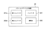
図2に、本実施の形態におけるパワーコンディショナ装置20のブロック図が示されている。図2に示すように、パワーコンディショナ装置20は、第1コンバータ201aと、インバータ201と、第2コンバータ202aと、蓄電池202と、を含んでいる。   FIG. 2 is a block diagram of the power conditioner device 20 in the present embodiment. As shown in FIG. 2, the power conditioner device 20 includes a first converter 201 a, an inverter 201, a second converter 202 a, and a storage battery 202.

このうち第1コンバータ201aには、自然エネルギー発電装置10から電力線を介して直流電力が供給されるようになっており、第1コンバータ201aは、供給された電力を、所定の電圧幅内に収まるように調整する。インバータ201は、第1コンバータ201aによって調整された直流電力を交流電力に変換する。第2コンバータ202aは、インバータ201で変換された交流電力を、所定の電圧幅内に収まるように調整する。蓄電池202は、第2コンバータ202aによって調整された交流電力を蓄電する。このようにして、自然エネルギー発電装置10によって発電された電力が、蓄電池202に蓄電される。蓄電された電力は、第2コンバータ202aおよびインバータ201を介してパワーコンディショナ装置20から出力され、負荷部3または水素発生装置40に供給されるようになっている。なお、蓄電池202は、例えば、リチウムイオン二次電池とすることができる。   Among these, DC power is supplied to the first converter 201a from the natural energy power generation apparatus 10 via the power line, and the first converter 201a fits the supplied power within a predetermined voltage range. Adjust as follows. The inverter 201 converts the DC power adjusted by the first converter 201a into AC power. Second converter 202a adjusts the AC power converted by inverter 201 so as to be within a predetermined voltage range. The storage battery 202 stores the AC power adjusted by the second converter 202a. In this way, the electric power generated by the natural energy power generation apparatus 10 is stored in the storage battery 202. The stored electric power is output from the power conditioner device 20 via the second converter 202a and the inverter 201, and is supplied to the load unit 3 or the hydrogen generator 40. The storage battery 202 can be, for example, a lithium ion secondary battery.

パワーコンディショナ装置20には、自然エネルギー発電装置10以外にも、燃料電池発電装置60から発電された電力が供給され、蓄電池202に蓄電されるようになっている。また、パワーコンディショナ装置20には、電力系統2から電力が供給されるようになっている。この電力系統2から供給される電力を用いて、パワーコンディショナ装置20は動作するように構成されている。   In addition to the natural energy power generation device 10, the power conditioner device 20 is supplied with power generated from the fuel cell power generation device 60 and is stored in the storage battery 202. In addition, power is supplied from the power system 2 to the power conditioner device 20. The power conditioner device 20 is configured to operate using the power supplied from the power system 2.

図1に示すように、貯水装置30は、水を貯蔵し、貯蔵された水を水素発生装置40に供給するように構成されている。また、貯水装置30は、貯蔵された水を燃料電池発電装置60にも供給するようになっている。   As shown in FIG. 1, the water storage device 30 is configured to store water and supply the stored water to the hydrogen generator 40. In addition, the water storage device 30 supplies the stored water to the fuel cell power generation device 60.

具体的には、貯水装置30は、給水タンク(図示せず)を含んでおり、既設の水道設備を介して供給された水を給水タンクに貯蔵する。給水タンクに貯蔵された水は、水素発生装置40および燃料電池発電装置60に、ポンプ(図示せず)を介してそれぞれ供給される。なお、このようなポンプを用いることなく、水頭圧によって、水素発生装置40および燃料電池発電装置60に水を供給するように構成されていてもよい。   Specifically, the water storage device 30 includes a water supply tank (not shown), and stores water supplied through an existing water supply facility in the water supply tank. The water stored in the water supply tank is supplied to the hydrogen generator 40 and the fuel cell power generator 60 via a pump (not shown). In addition, you may be comprised so that water may be supplied to the hydrogen generator 40 and the fuel cell power generation device 60 by water head pressure, without using such a pump.

また、貯水装置30は、燃料電池発電装置60に供給された水が戻るように構成されている。すなわち、燃料電池発電装置60に供給された水が、燃料電池発電装置60において加熱されて温水(熱媒)となり、この温水が貯水装置30に戻される場合がある。このようにして戻される温水は、給水タンクで貯蔵されるようにしてもよい。   In addition, the water storage device 30 is configured such that water supplied to the fuel cell power generation device 60 returns. That is, the water supplied to the fuel cell power generation device 60 is heated in the fuel cell power generation device 60 to become hot water (heat medium), and this hot water may be returned to the water storage device 30 in some cases. The warm water returned in this way may be stored in a water supply tank.

図1に示すように、水素発生装置40は、水素を発生させるように構成されている。水素発生装置40には、パワーコンディショナ装置20から電力が供給される。より具体的には、水素発生装置40は、自然エネルギー発電装置10が発電した電力と、電力系統2から供給された電力の少なくとも一方を用いて、水の電気分解を行い、水素を製造する。   As shown in FIG. 1, the hydrogen generator 40 is configured to generate hydrogen. Electric power is supplied from the power conditioner device 20 to the hydrogen generator 40. More specifically, the hydrogen generator 40 produces hydrogen by electrolyzing water using at least one of the electric power generated by the natural energy power generation apparatus 10 and the electric power supplied from the electric power system 2.

図3に、本実施の形態における水素発生装置40のブロック図が示されている。図3に示すように、水素発生装置40は、純水製造装置401aと、水電解装置401と、を含んでいる。純水製造装置401aには、貯水装置30から水が供給され、純水製造装置401aは、供給された水から不純物を除去する。水電解装置401は、不純物が除去された水(純水)に電気を流し、水を水素と酸素に電気分解する。このようにして、水素が製造される。製造された水素は、水素貯蔵装置50に供給されて貯蔵される。一方、水電解装置401において生成された酸素は、大気に放出される。なお、水電解装置401は、例えば、固体高分子型(PEM)水電解装置とすることができるが、これ以外にも、例えば、SOEC(Solid Oxide Electrolysis Cell)による高温水蒸気電解装置としてもよい。   FIG. 3 shows a block diagram of the hydrogen generator 40 in the present embodiment. As shown in FIG. 3, the hydrogen generator 40 includes a pure water production apparatus 401 a and a water electrolysis apparatus 401. Water is supplied from the water storage device 30 to the pure water production apparatus 401a, and the pure water production apparatus 401a removes impurities from the supplied water. The water electrolysis apparatus 401 supplies electricity to water from which impurities have been removed (pure water), and electrolyzes the water into hydrogen and oxygen. In this way, hydrogen is produced. The produced hydrogen is supplied to the hydrogen storage device 50 and stored. On the other hand, oxygen generated in the water electrolysis apparatus 401 is released to the atmosphere. The water electrolysis apparatus 401 can be, for example, a solid polymer type (PEM) water electrolysis apparatus, but can also be a high temperature steam electrolysis apparatus using, for example, SOEC (Solid Oxide Electrolysis Cell).

また、図3に示すように、水素発生装置40は、コンプレッサ402と、チラーユニット403と、を更に含んでいる。このうちコンプレッサ402は、空気を圧縮して水電解装置401に供給する。チラーユニット403は、冷却水を水電解装置401に供給する。   As shown in FIG. 3, the hydrogen generator 40 further includes a compressor 402 and a chiller unit 403. Among these, the compressor 402 compresses air and supplies it to the water electrolysis apparatus 401. The chiller unit 403 supplies cooling water to the water electrolysis apparatus 401.

さらに、水素発生装置40は、ガスセンサ、圧力計、流量計などの計測機器(図示せず)を更に含んでいる。これらの計測機器によって計測されたデータは、データ信号として制御装置70に出力される。   Furthermore, the hydrogen generator 40 further includes measuring devices (not shown) such as a gas sensor, a pressure gauge, and a flow meter. Data measured by these measuring devices is output to the control device 70 as a data signal.

図1に示すように、水素貯蔵装置50は、水素発生装置40により発生した水素を貯蔵するように構成されている。   As shown in FIG. 1, the hydrogen storage device 50 is configured to store hydrogen generated by the hydrogen generation device 40.

図4に、本実施の形態における水素貯蔵装置50のブロック図が示されている。図4に示すように、水素貯蔵装置50は、水素貯蔵タンク501と、電磁弁502と、安全弁503と、を含んでいる。このうち水素貯蔵タンク501には、水素発生装置40によって製造された水素が、電磁弁502を介して供給されるようになっている。供給された水素は、水素貯蔵タンク501に貯蔵される。   FIG. 4 shows a block diagram of the hydrogen storage device 50 in the present embodiment. As shown in FIG. 4, the hydrogen storage device 50 includes a hydrogen storage tank 501, an electromagnetic valve 502, and a safety valve 503. Among these, hydrogen produced by the hydrogen generator 40 is supplied to the hydrogen storage tank 501 via an electromagnetic valve 502. The supplied hydrogen is stored in the hydrogen storage tank 501.

水素貯蔵装置50は、ガスセンサ、圧力計、流量計などの計測機器(図示せず)を更に含んでいる。これらの計測機器によって計測されたデータは、データ信号として制御装置70に出力される。   The hydrogen storage device 50 further includes measuring devices (not shown) such as a gas sensor, a pressure gauge, and a flow meter. Data measured by these measuring devices is output to the control device 70 as a data signal.

図1に示すように、燃料電池発電装置60は、水素貯蔵装置50に貯蔵された水素を用いて発電を行い、その発電によって発生した電力を負荷部3に出力するように構成されている。また、燃料電池発電装置60は、発電で生じた熱を用いて、貯水装置30から供給された水を加熱し温水を生成するように構成されていてもよい。そして、生成された温水を負荷部3(温水消費先)に供給するように構成されている。   As shown in FIG. 1, the fuel cell power generation device 60 is configured to generate power using the hydrogen stored in the hydrogen storage device 50 and output the power generated by the power generation to the load unit 3. Further, the fuel cell power generation device 60 may be configured to heat the water supplied from the water storage device 30 and generate hot water using heat generated by power generation. And it is comprised so that the produced | generated hot water may be supplied to the load part 3 (hot water consumption destination).

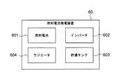
図5に、本実施の形態による燃料電池発電装置60のブロック図が示されている。図5に示すように、燃料電池発電装置60は、燃料電池601と、インバータ602と、貯湯タンク603と、ラジエータ604と、を含んでいる。このうち燃料電池601には、水素貯蔵装置50から水素が供給されるようになっており、燃料電池601は、供給された水素を用いて発電を行う。なお、燃料電池601は、例えば、固体高分子形燃料電池(PEFC)とすることができる。インバータ602は、燃料電池601によって発電された電力を、負荷部3で利用可能な電力に変換する。   FIG. 5 shows a block diagram of a fuel cell power generator 60 according to the present embodiment. As shown in FIG. 5, the fuel cell power generator 60 includes a fuel cell 601, an inverter 602, a hot water storage tank 603, and a radiator 604. Among these, the fuel cell 601 is supplied with hydrogen from the hydrogen storage device 50, and the fuel cell 601 generates power using the supplied hydrogen. The fuel cell 601 can be, for example, a polymer electrolyte fuel cell (PEFC). The inverter 602 converts the electric power generated by the fuel cell 601 into electric power that can be used by the load unit 3.

貯湯タンク603は、燃料電池601の発電で生じた熱を用いて生成された温水を貯蔵し、貯蔵した温水を負荷部3に供給する。ラジエータ604は、燃料電池601の発電で生じた熱を放熱するように構成されている。より具体的には、ラジエータ604は、貯蔵タンク603から負荷部3に供給される温水の供給量が、負荷部3において使用される温水の使用量よりも多くなる場合に、燃料電池601の発電で生じた熱を放熱する。   The hot water storage tank 603 stores hot water generated by using heat generated by the power generation of the fuel cell 601 and supplies the stored hot water to the load unit 3. The radiator 604 is configured to dissipate heat generated by the power generation of the fuel cell 601. More specifically, the radiator 604 generates power from the fuel cell 601 when the amount of hot water supplied from the storage tank 603 to the load unit 3 is larger than the amount of hot water used in the load unit 3. Dissipate the heat generated in.

燃料電池発電装置60は、ガスセンサ、圧力計、流量計などの計測機器を更に含んでいる。これらの計測機器によって計測されたデータは、データ信号として制御装置70に出力される。   The fuel cell power generator 60 further includes measuring devices such as a gas sensor, a pressure gauge, and a flow meter. Data measured by these measuring devices is output to the control device 70 as a data signal.

図1に示すように、制御装置70は、水素システム1を構成する各装置を制御するように構成されている。制御装置70は、図示しない演算器およびメモリを含んでおり、メモリが記憶しているプログラムを用いて演算器が演算処理を行うことによって、各装置の制御を行う。   As shown in FIG. 1, the control device 70 is configured to control each device constituting the hydrogen system 1. The control device 70 includes an arithmetic unit and a memory (not shown), and the arithmetic unit performs arithmetic processing using a program stored in the memory, thereby controlling each device.

制御装置70には、各装置の計測機器により計測されたデータがデータ信号として入力される。また、制御装置70には、負荷部3において使用される電力の使用量がデータ信号として入力される。例えば、予め定められた時間(30分間)において負荷部3で使用された電力の使用量のデータ信号が、制御装置70に入力される。また、制御装置70には、電力系統2から供給される電力の供給量、負荷部3において使用される温水の使用量、自然エネルギー発電装置10から出力される電力の出力量、パワーコンディショナ装置20に含まれる蓄電池202の蓄電量、燃料電池発電装置60から出力される電力の出力量、貯水装置30が貯蔵している水の貯蔵量、水素貯蔵装置50が貯蔵している水素の貯蔵量、燃料電池発電装置60に貯蔵された温水の貯蔵量などのデータが、データ信号として入力される。そして、制御装置70は、入力されたデータ信号に基づいて演算を行い、制御信号を水素システム1の各装置に出力する。このようにして、制御装置70が水素システム1の各装置の動作を制御し、最適な運転となるように制御を行う。   Data measured by the measuring device of each device is input to the control device 70 as a data signal. Further, the amount of power used in the load unit 3 is input to the control device 70 as a data signal. For example, a data signal of the amount of power used by the load unit 3 during a predetermined time (30 minutes) is input to the control device 70. Further, the control device 70 includes a supply amount of power supplied from the power system 2, a use amount of hot water used in the load unit 3, an output amount of power output from the natural energy power generation device 10, and a power conditioner device. 20, the storage amount of the storage battery 202, the output amount of power output from the fuel cell power generator 60, the storage amount of water stored in the water storage device 30, the storage amount of hydrogen stored in the hydrogen storage device 50 Data such as the amount of hot water stored in the fuel cell power generator 60 is input as a data signal. Then, the control device 70 performs an operation based on the input data signal and outputs a control signal to each device of the hydrogen system 1. In this way, the control device 70 controls the operation of each device of the hydrogen system 1 and performs control so as to achieve optimum operation.

例えば、制御装置70は、平常時、負荷部3で使用されている電力の使用量が予め定めた所定値よりも多い場合には、水素システム1から負荷部3に電力を供給するように制御を行う。ここで、平常時とは、電力系統2から負荷部3へ電力が供給されている状態を意味する。この場合、自然エネルギー発電装置10から出力される電力の出力量、燃料電池発電装置60から出力される電力の出力量、蓄電池202の蓄電量等に基づいて、各装置から電力を適宜集めて負荷部3に供給する。また、制御装置70は、負荷部3で使用されている温水の使用量に基づいて、燃料電池発電装置60から温水を負荷部3に供給する。   For example, the control device 70 performs control so that power is supplied from the hydrogen system 1 to the load unit 3 when the amount of power used by the load unit 3 is larger than a predetermined value in a normal state. I do. Here, the normal state means a state in which power is supplied from the power system 2 to the load unit 3. In this case, based on the output amount of power output from the natural energy power generation device 10, the output amount of power output from the fuel cell power generation device 60, the storage amount of the storage battery 202, and the like, power is appropriately collected from each device and loaded. Supply to part 3. Further, the control device 70 supplies hot water from the fuel cell power generator 60 to the load unit 3 based on the amount of hot water used in the load unit 3.

一方、災害等によって停電が発生した異常時には、電力系統2から負荷部3へ電力が供給されない場合がある。このような異常時には、制御装置70は、水素システム1から負荷部3へ電力を供給するように制御を行う。この場合、制御装置70は、自然エネルギー発電装置10で発電された電力を用いて水素発生装置40が水素を製造し、燃料電池発電装置60が発電を行うように制御を行う。そして、制御装置70は、自然エネルギー発電装置10から出力される電力の出力量、燃料電池発電装置60から出力される電力の出力量、蓄電池202の蓄電量等に基づいて、各装置から電力を適宜集めて負荷部3に供給する。また、異常時においても、制御装置70は、燃料電池発電装置60から温水を負荷部3に供給する。   On the other hand, in the event of a power outage due to a disaster or the like, power may not be supplied from the power system 2 to the load unit 3. When such an abnormality occurs, the control device 70 performs control to supply power from the hydrogen system 1 to the load unit 3. In this case, the control device 70 performs control so that the hydrogen generator 40 produces hydrogen using the power generated by the natural energy power generator 10 and the fuel cell power generator 60 generates power. Then, the control device 70 receives power from each device based on the output amount of power output from the natural energy power generation device 10, the output amount of power output from the fuel cell power generation device 60, the storage amount of the storage battery 202, and the like. Collected appropriately and supplied to the load section 3. In addition, the control device 70 supplies hot water from the fuel cell power generation device 60 to the load unit 3 even during an abnormality.

ところで、平常時であるか異常時であるかの判断は、制御装置70により行われる。すなわち、制御装置70は、電力系統2から供給される電力の供給量を監視することによって、平常時であるか異常時であるかを判断する。より具体的には、電力系統2から電力が供給された状態である場合に平常時であると判断され、電力系統2と水素システム1との接続が保持される。一方、電力系統2から電力が供給されずに電力供給が停止した状態である場合には、災害時等の異常時であると判断され、電力系統2と水素システム1との接続が遮断される。   By the way, the control device 70 determines whether it is normal or abnormal. That is, the control device 70 determines whether it is normal or abnormal by monitoring the amount of power supplied from the power system 2. More specifically, when power is supplied from the power system 2, it is determined as normal, and the connection between the power system 2 and the hydrogen system 1 is maintained. On the other hand, when the power supply is not supplied from the power system 2 and the power supply is stopped, it is determined that there is an abnormality such as a disaster, and the connection between the power system 2 and the hydrogen system 1 is cut off. .

また、制御装置70は、時間帯の判断も行う。すなわち、制御装置70は、時刻に基づいて時間帯が昼であるか夜であるかを判断し、判断された時間帯に基づいて各装置の制御を行う。   The control device 70 also determines the time zone. That is, the control device 70 determines whether the time zone is daytime or night based on the time, and controls each device based on the determined time zone.

さらに、制御装置70は、天候の判断も行う。すなわち、制御装置70は、自然エネルギー発電装置10から出力される電力の出力量に基づいて、天候を判断する。より具体的には、制御装置70は、時間帯が昼の場合において、自然エネルギー発電装置10から出力される電力の出力量が予め定めた所定量よりも多い場合には天候が晴れであると判断し、当該所定量以下である場合には天候が曇り若しくは雨であると判断する。そして、制御装置70は、判断された天候に基づいて各装置の制御を行う。   Furthermore, the control device 70 also determines the weather. That is, the control device 70 determines the weather based on the output amount of power output from the natural energy power generation device 10. More specifically, when the time zone is daytime, the control device 70 determines that the weather is clear when the output amount of power output from the natural energy power generation device 10 is greater than a predetermined amount. If it is less than the predetermined amount, it is determined that the weather is cloudy or rainy. And the control apparatus 70 controls each apparatus based on the judged weather.

上述した以外にも、制御装置70は、水素貯蔵装置50に貯蔵された水素の貯蔵量に基づいて水素を製造するように水素発生装置40の動作を制御する。   In addition to the above, the control device 70 controls the operation of the hydrogen generation device 40 so as to produce hydrogen based on the amount of hydrogen stored in the hydrogen storage device 50.

また、制御装置70は、燃料電池発電装置60から出力される電力と電力系統2から供給される電力との合計供給量が、水素システム1および負荷部3において使用される電力の合計使用量よりも多い場合、燃料電池発電装置60で発電された電力をパワーコンディショナ装置20の蓄電池202に蓄電させる。より具体的には、当該合計供給量が当該合計使用量よりも多いか否かを制御装置70が判断する。そして、制御装置70は、合計供給量が合計使用量よりも多いと判断した場合、燃料電池発電装置60で発電された電力を、負荷部3へ出力することなく、蓄電池202に出力して蓄電させる。このようにして、本実施の形態では、水素システム1で発電された電力が効果的に利用される。   Further, the control device 70 determines that the total supply amount of the power output from the fuel cell power generation device 60 and the power supplied from the power system 2 is greater than the total power consumption used in the hydrogen system 1 and the load unit 3. In many cases, the electric power generated by the fuel cell power generation device 60 is stored in the storage battery 202 of the power conditioner device 20. More specifically, the control device 70 determines whether or not the total supply amount is larger than the total use amount. When the control device 70 determines that the total supply amount is larger than the total use amount, the power generated by the fuel cell power generation device 60 is output to the storage battery 202 and stored without being output to the load unit 3. Let Thus, in this Embodiment, the electric power generated with the hydrogen system 1 is used effectively.

また、制御装置70は、燃料電池発電装置60から負荷部3に供給される温水の供給量が、負荷部3において使用される温水の使用量よりも多い場合、燃料電池発電装置60で生成された温水を貯水装置30に戻す。より具体的には、温水の供給量が、温水の使用量よりも多いか否かを制御装置70が判断する。そして、制御装置70が、供給量が使用量よりも多いと判断した場合、燃料電池発電装置60で貯蔵された温水を、負荷部3へ供給することなく貯水装置30に供給する。これにより、貯水装置30から水素発生装置40へ供給するための水を確保することができる。この場合、燃料電池発電装置60の発電で生じた熱をラジエータ604によって放熱することが好適である。   Further, when the supply amount of hot water supplied from the fuel cell power generation device 60 to the load unit 3 is larger than the usage amount of hot water used in the load unit 3, the control device 70 is generated by the fuel cell power generation device 60. The warm water is returned to the water storage device 30. More specifically, the control device 70 determines whether or not the amount of hot water supplied is larger than the amount of hot water used. When the control device 70 determines that the supply amount is larger than the usage amount, the hot water stored in the fuel cell power generation device 60 is supplied to the water storage device 30 without being supplied to the load unit 3. Thereby, the water for supplying to the hydrogen generator 40 from the water storage apparatus 30 is securable. In this case, it is preferable to dissipate heat generated by the power generation of the fuel cell power generator 60 by the radiator 604.

更に、制御装置70は、自然エネルギー発電装置10から出力される電力の出力量に基づいて、水素システム1の各装置の制御を行う。   Furthermore, the control device 70 controls each device of the hydrogen system 1 based on the output amount of power output from the natural energy power generation device 10.

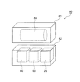
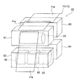
図6に示すように、上述した水素システム1を構成する装置のうち、パワーコンディショナ装置20、水素発生装置40、水素貯蔵装置50および燃料電池発電装置60は、2つのコンテナに収容されている。これらの2つのコンテナが組み合わされて本実施の形態における水素システム用コンテナ組合体80が構成されている。   As shown in FIG. 6, among the devices constituting the hydrogen system 1 described above, the power conditioner device 20, the hydrogen generator 40, the hydrogen storage device 50, and the fuel cell power generator 60 are accommodated in two containers. . These two containers are combined to form a hydrogen system container assembly 80 in the present embodiment.

本実施の形態による水素システム用コンテナ組合体80は、2つのコンテナによって構成されており、第1コンテナ81と第2コンテナ82とを備えている。第1コンテナ81および第2コンテナ82は、図7乃至図10に示すように、それぞれ直方体状に形成されている。   The hydrogen system container assembly 80 according to the present embodiment includes two containers, and includes a first container 81 and a second container 82. As shown in FIGS. 7 to 10, the first container 81 and the second container 82 are each formed in a rectangular parallelepiped shape.

図1、図6および図7に示すように、第1コンテナ81には、水素貯蔵装置50が収容されている。より具体的には、第1コンテナ81内には、水素貯蔵装置50を構成する水素貯蔵タンク501、電磁弁502および安全弁503(図4参照)が収容されている。これらの構成部品は、配管等によって互いに接続されている。   As shown in FIGS. 1, 6 and 7, a hydrogen storage device 50 is accommodated in the first container 81. More specifically, in the first container 81, a hydrogen storage tank 501, a solenoid valve 502, and a safety valve 503 (see FIG. 4) constituting the hydrogen storage device 50 are accommodated. These components are connected to each other by piping or the like.

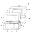
第2コンテナ82に、パワーコンディショナ装置20、水素発生装置40および燃料電池発電装置60が収容されている。本実施の形態においては、パワーコンディショナ装置20は、第2コンテナ82の長手方向において一端側に位置し、燃料電池発電装置60は、第2コンテナ82の長手方向において他端側に位置している。そして、水素発生装置40は、第2コンテナ82の長手方向において中央側、すなわちパワーコンディショナ装置20と燃料電池発電装置60との間に配置されている。パワーコンディショナ装置20と水素発生装置40とは、配線等によって互いに接続されており、パワーコンディショナ装置20と燃料電池発電装置60とは、配線等によって互いに接続されている。なお、第2コンテナ82内における各装置20、40、60の配置は、これに限られることはない。   In the second container 82, the power conditioner device 20, the hydrogen generator 40, and the fuel cell power generator 60 are accommodated. In the present embodiment, the power conditioner device 20 is located on one end side in the longitudinal direction of the second container 82, and the fuel cell power generator 60 is located on the other end side in the longitudinal direction of the second container 82. Yes. The hydrogen generator 40 is arranged at the center in the longitudinal direction of the second container 82, that is, between the power conditioner device 20 and the fuel cell power generator 60. The power conditioner device 20 and the hydrogen generator 40 are connected to each other by wiring or the like, and the power conditioner device 20 and the fuel cell power generator 60 are connected to each other by wiring or the like. In addition, arrangement | positioning of each apparatus 20,40,60 in the 2nd container 82 is not restricted to this.

図9に示すように、第2コンテナ82内には、パワーコンディショナ装置20を構成する第1コンバータ201a、インバータ201、第2コンバータ202aおよび蓄電池202が収容されている。これらの構成部品は、配線等によって互いに接続されている。また、第2コンテナ82内には、水素発生装置40を構成する純水製造装置401a、水電解装置401、コンプレッサ402およびチラーユニット403が収容されている。これらの構成部品は、配管等で接続されている。さらに、第2コンテナ82内には、燃料電池発電装置60を構成する燃料電池601、インバータ602、貯湯タンク603およびラジエータ604が収容されている。これらの構成部品は、配線や配管等によって互いに接続されている。   As shown in FIG. 9, a first converter 201 a, an inverter 201, a second converter 202 a, and a storage battery 202 constituting the power conditioner device 20 are housed in the second container 82. These components are connected to each other by wiring or the like. In the second container 82, a pure water production apparatus 401a, a water electrolysis apparatus 401, a compressor 402, and a chiller unit 403 constituting the hydrogen generation apparatus 40 are accommodated. These components are connected by piping or the like. Further, the second container 82 accommodates a fuel cell 601, an inverter 602, a hot water storage tank 603, and a radiator 604 that constitute the fuel cell power generator 60. These components are connected to each other by wiring, piping, or the like.

第1コンテナ81および第2コンテナ82は、例えば、運搬用として規格化されたコンテナの大きさで形成されており、運搬可能な大きさとなっている。特に、第1コンテナ81および第2コンテナ82は、規格化された20フィートコンテナまたは12フィートコンテナの大きさで形成されていることが好適である。20フィートコンテナは、ISO規格で規定されており、長さWが6096mm、幅Dが2438mm、高さHが2591mmである。また、12フィートコンテナも同様にISO規格で規定されており、長さWが3600mm、幅Dが2438mm、高さHが2591mmである。   The 1st container 81 and the 2nd container 82 are formed in the size of the container standardized for carrying, for example, and become the size which can be carried. In particular, the first container 81 and the second container 82 are preferably formed in a standardized size of a 20-foot container or a 12-foot container. The 20-foot container is defined by the ISO standard, and has a length W of 6096 mm, a width D of 2438 mm, and a height H of 2591 mm. The 12-foot container is similarly defined by the ISO standard, and has a length W of 3600 mm, a width D of 2438 mm, and a height H of 2591 mm.

図6に示すように、水素システム1の設置場所において、第1コンテナ81は、第2コンテナ82上に縦積みされている。より具体的には、第1コンテナ81と第2コンテナ82は、上方から見た場合に整列されて重なり、各コンテナ81、82の長手方向が一致するように縦積みされている。そして、第1コンテナ81の水素貯蔵装置50と、第2コンテナ82の水素発生装置40とが、配管等によって互いに接続されており、第1コンテナ81の水素貯蔵装置50と、第2コンテナ82の燃料電池発電装置60とが、配管等によって互いに接続されている。また、第1コンテナ81に収容された水素貯蔵装置50と、第2コンテナ82に収容されたパワーコンディショナ装置20、水素発生装置40および燃料電池発電装置60が、水素システム1を構成する他の装置(すなわち、自然エネルギー発電装置10、貯水装置30、制御装置70)に、配管や配線等によって接続されている。なお、図6においては、図面を明瞭にするために、第1コンテナ81と第2コンテナ82とが離間した状態を示しているが、第1コンテナ81は、第2コンテナ82上に直接的に載置されて縦積みされていてもよく、または、何らかの部材を介在させて第2コンテナ82上に載置されて縦積みされていてもよい。   As shown in FIG. 6, the first container 81 is vertically stacked on the second container 82 at the location where the hydrogen system 1 is installed. More specifically, the first container 81 and the second container 82 are aligned and overlapped when viewed from above, and are vertically stacked so that the longitudinal directions of the containers 81 and 82 coincide. The hydrogen storage device 50 of the first container 81 and the hydrogen generation device 40 of the second container 82 are connected to each other by piping or the like, and the hydrogen storage device 50 of the first container 81 and the second container 82 are connected to each other. The fuel cell power generator 60 is connected to each other by piping or the like. In addition, the hydrogen storage device 50 accommodated in the first container 81, the power conditioner device 20, the hydrogen generator 40, and the fuel cell power generator 60 accommodated in the second container 82 are the other constituents of the hydrogen system 1. It is connected to a device (that is, a natural energy power generation device 10, a water storage device 30, and a control device 70) by piping or wiring. In FIG. 6, for the sake of clarity, the first container 81 and the second container 82 are separated from each other. However, the first container 81 is directly on the second container 82. It may be placed and stacked vertically, or may be placed on the second container 82 and stacked vertically with some member interposed therebetween.

次に、このような構成からなる本実施の形態の作用について説明する。ここでは、まず、水素システム1を設置する方法について説明する。   Next, the operation of the present embodiment having such a configuration will be described. Here, first, a method of installing the hydrogen system 1 will be described.

まず、第1コンテナ81に水素貯蔵装置50が収容される。この場合、水素貯蔵装置50の構成部品が配管等によって互いに接続される。同様にして、第2コンテナ82に、パワーコンディショナ装置20、水素発生装置40および燃料電池発電装置60が収容される。この場合、パワーコンディショナ装置20の構成部品、水素発生装置40の構成部品および燃料電池発電装置60の構成部品が、配管や配線等によって互いに接続される。   First, the hydrogen storage device 50 is accommodated in the first container 81. In this case, the components of the hydrogen storage device 50 are connected to each other by piping or the like. Similarly, the power conditioner device 20, the hydrogen generator 40, and the fuel cell power generator 60 are accommodated in the second container 82. In this case, the components of the power conditioner device 20, the components of the hydrogen generator 40, and the components of the fuel cell power generator 60 are connected to each other by piping, wiring, or the like.

続いて、水素貯蔵装置50が収容された第1コンテナ81と、パワーコンディショナ装置20、水素発生装置40および燃料電池発電装置60が収容された第2コンテナ82とが、別々に運搬される。   Then, the 1st container 81 in which the hydrogen storage apparatus 50 was accommodated, and the 2nd container 82 in which the power conditioner apparatus 20, the hydrogen generator 40, and the fuel cell power generation apparatus 60 were accommodated are conveyed separately.

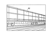
ここで、第1コンテナ81および第2コンテナ82は、運搬用として規格化されていることから、例えば、図11に示すように、鉄道を利用して運搬することができる。あるいは、図12に示すように、第1コンテナ81および第2コンテナ82は、フォークリフトを利用して運搬することができ、図13に示すように、船を利用して運搬することもできる。更には、図14に示すように、これらのコンテナ81、82は、トレーラを利用して運搬することもできる。なお、図11乃至図14においては、代表例として、第2コンテナ82を図示しているが、第1コンテナ81も同様に運搬することができる。   Here, since the first container 81 and the second container 82 are standardized for transportation, for example, as shown in FIG. 11, they can be transported using a railway. Or as shown in FIG. 12, the 1st container 81 and the 2nd container 82 can be conveyed using a forklift, and can also be conveyed using a ship as shown in FIG. Furthermore, as shown in FIG. 14, these containers 81 and 82 can be transported using a trailer. In addition, in FIG. 11 thru | or FIG. 14, although the 2nd container 82 is illustrated as a typical example, the 1st container 81 can also be conveyed similarly.

このようにして、第1コンテナ81および第2コンテナ82は、陸上輸送および海上輸送によって容易に運搬することができ、第1コンテナ81および第2コンテナ82の運搬先に制約が課されることを防止できる。また、災害が発生した場合であっても、適切な運搬方法を選択して、第1コンテナ81および第2コンテナ82を所望の設置場所に迅速かつ容易に運搬することができる。このため、水素システム1の設置場所に制約が課されることを防止できる。   In this manner, the first container 81 and the second container 82 can be easily transported by land transportation and sea transportation, and restrictions are imposed on the transportation destination of the first container 81 and the second container 82. Can be prevented. Further, even when a disaster occurs, an appropriate transportation method can be selected and the first container 81 and the second container 82 can be transported quickly and easily to a desired installation location. For this reason, it can prevent that restrictions are imposed on the installation location of the hydrogen system 1.

第1コンテナ81および第2コンテナ82は、設置場所に運搬された後、当該設置場所に設置される。この場合、まず、第2コンテナ82が、コンクリートの基礎上に設置される。その後、第2コンテナ82上に第1コンテナ81が載置され、第1コンテナ81が第2コンテナ82上に縦積みされる。   The first container 81 and the second container 82 are transported to the installation location and then installed at the installation location. In this case, first, the second container 82 is installed on a concrete foundation. Thereafter, the first container 81 is placed on the second container 82, and the first container 81 is stacked vertically on the second container 82.

第1コンテナ81が第2コンテナ82上に縦積みされた後、第1コンテナ81内の水素貯蔵装置50と、第2コンテナ82内のパワーコンディショナ装置20、水素発生装置40および燃料電池発電装置60が、配管や配線等によって互いに接続される。また、自然エネルギー発電装置10が第2コンテナ82内のパワーコンディショナ装置20に配線等によって接続され、貯水装置30が、第2コンテナ82内の水素発生装置40および燃料電池発電装置60に配管等によって接続される。このようにして、図1に示す本実施の形態による水素システム1が得られる。   After the first container 81 is vertically stacked on the second container 82, the hydrogen storage device 50 in the first container 81, the power conditioner device 20 in the second container 82, the hydrogen generator 40, and the fuel cell power generator 60 are connected to each other by piping, wiring or the like. Further, the natural energy power generation device 10 is connected to the power conditioner device 20 in the second container 82 by wiring or the like, and the water storage device 30 is connected to the hydrogen generator 40 and the fuel cell power generation device 60 in the second container 82. Connected by. In this way, the hydrogen system 1 according to the present embodiment shown in FIG. 1 is obtained.

次に、本実施の形態による水素システム1の動作について説明する。   Next, the operation of the hydrogen system 1 according to the present embodiment will be described.

図15に、本実施の形態による水素システム1の動作の一例が示されている。図15では、水素システム1の各装置が発電または運転を行う場合に「ON」と表記し、発電または運転を停止する場合に「OFF」を表記している。   FIG. 15 shows an example of the operation of the hydrogen system 1 according to the present embodiment. In FIG. 15, “ON” is written when each device of the hydrogen system 1 performs power generation or operation, and “OFF” is written when power generation or operation is stopped.

まず、平常時の水素システム1の動作について説明する。ここでは、まず、時間帯が昼であって天候が晴れである場合について説明する。   First, the operation of the hydrogen system 1 during normal times will be described. Here, a case where the time zone is noon and the weather is clear will be described.

この場合、太陽光発電装置である自然エネルギー発電装置10が発電を行う。この自然エネルギー発電装置10により発電された電力は、パワーコンディショナ装置20を介して水素発生装置40に供給され、水素発生装置40において水素の製造に利用される。製造された水素は、水素貯蔵装置50に供給されて貯蔵される。   In this case, the natural energy power generation device 10 that is a solar power generation device generates power. The electric power generated by the natural energy power generation apparatus 10 is supplied to the hydrogen generation apparatus 40 via the power conditioner apparatus 20 and is used for hydrogen production in the hydrogen generation apparatus 40. The produced hydrogen is supplied to the hydrogen storage device 50 and stored.

自然エネルギー発電装置10により発電された電力が水素発生装置40で要求される電力よりも多いときには、自然エネルギー発電装置10により発電された電力は、負荷部3に供給されてもよい。このとき、自然エネルギー発電装置10により発電された電力は、パワーコンディショナ装置20の蓄電池202に充電されてもよい。   When the electric power generated by the natural energy power generation device 10 is larger than the power required by the hydrogen generator 40, the electric power generated by the natural energy power generation device 10 may be supplied to the load unit 3. At this time, the electric power generated by the natural energy power generation apparatus 10 may be charged in the storage battery 202 of the power conditioner apparatus 20.

一方、自然エネルギー発電装置10により発電された電力が水素発生装置40で要求される電力よりも少ないときには、蓄電池202で蓄電された電力が放電されて水素発生装置40に供給され、水素の製造に補助的に利用される。   On the other hand, when the electric power generated by the natural energy generator 10 is less than the electric power required by the hydrogen generator 40, the electric power stored in the storage battery 202 is discharged and supplied to the hydrogen generator 40 for the production of hydrogen. Used as an auxiliary.

また、この場合、燃料電池発電装置60は、水素貯蔵装置50から供給される水素を用いて発電を行う。発電により得られた電力は負荷部3に供給される。また、燃料電池発電装置60は、発電で生じた熱を用いて、貯水装置30から供給される水を加熱して温水を生成する。生成された温水は負荷部3に供給される。   In this case, the fuel cell power generation device 60 generates power using the hydrogen supplied from the hydrogen storage device 50. The electric power obtained by power generation is supplied to the load unit 3. In addition, the fuel cell power generator 60 uses the heat generated by the power generation to heat the water supplied from the water storage device 30 and generate hot water. The generated hot water is supplied to the load unit 3.

次に、平常時で時間帯が昼であって天候が曇り若しくは雨である場合について説明する。   Next, the case where the time zone is normal and the weather is cloudy or rainy will be described.

この場合、太陽光発電装置である自然エネルギー発電装置10は発電を行うが、発電される電力は、天候が晴れの場合よりも少なくなる。このため、自然エネルギー発電装置10で発電された電力は、水素発生装置40には供給されることなく、パワーコンディショナ装置20を介して負荷部3に供給されるとともにパワーコンディショナ装置20の蓄電池202に充電される。この場合、水素発生装置40は水素の製造を停止する。蓄電池202で蓄電された電力は、水素の製造が停止されているため、水素発生装置40に供給されない。すなわち、蓄電池202は放電を停止する。   In this case, the natural energy power generation device 10 that is a solar power generation device generates power, but the generated power is less than when the weather is sunny. For this reason, the electric power generated by the natural energy generator 10 is not supplied to the hydrogen generator 40 but is supplied to the load unit 3 via the power conditioner 20 and the storage battery of the power conditioner 20 202 is charged. In this case, the hydrogen generator 40 stops the production of hydrogen. The electric power stored in the storage battery 202 is not supplied to the hydrogen generator 40 because the production of hydrogen is stopped. That is, the storage battery 202 stops discharging.

燃料電池発電装置60は発電を行い、発電により得られた電力は負荷部3に供給される。また、燃料電池発電装置60は温水を生成し、生成された温水は負荷部3に供給される。上記以外の点は、天候が晴れである場合と同様に水素システム1の各装置は動作する。   The fuel cell power generator 60 generates power, and the power obtained by the power generation is supplied to the load unit 3. Further, the fuel cell power generator 60 generates hot water, and the generated hot water is supplied to the load unit 3. Other than the above, each device of the hydrogen system 1 operates in the same manner as when the weather is sunny.

また、この場合、電力系統2から供給された電力を用いて水素発生装置40が水素を製造するようにしてもよい。このことにより、水素貯蔵装置50に適正量の水素を容易に貯蔵することが可能となる。   In this case, the hydrogen generator 40 may produce hydrogen using the power supplied from the power system 2. As a result, an appropriate amount of hydrogen can be easily stored in the hydrogen storage device 50.

次に、平常時で時間帯が夜である場合について説明する。   Next, the case where the time zone is normal at night will be described.

この場合、太陽光発電装置である自然エネルギー発電装置10は発電を停止する。このため、自然エネルギー発電装置10から電力は出力されない。また、パワーコンディショナ装置20の蓄電池202は、充電を停止するとともに、蓄電された電力を放電する。放電された電力は負荷部3に供給される。供給された電力は、例えば、照明設備等の特定の負荷に利用され得る。なお、この蓄電池202から負荷部3への電力供給は、後述する燃料電池発電装置60から負荷部3への電力供給を補助するために行われる。   In this case, the natural energy power generation device 10 that is a solar power generation device stops power generation. For this reason, no electric power is output from the natural energy power generation apparatus 10. In addition, the storage battery 202 of the power conditioner device 20 stops charging and discharges the stored electric power. The discharged power is supplied to the load unit 3. The supplied power can be used for a specific load such as lighting equipment, for example. The power supply from the storage battery 202 to the load unit 3 is performed in order to assist the power supply from the fuel cell power generation device 60 described later to the load unit 3.

燃料電池発電装置60は発電を行い、発電により得られた電力は、負荷部3に供給される。また、燃料電池発電装置60は温水を生成し、生成された温水は負荷部3に供給される。   The fuel cell power generator 60 generates power, and the electric power obtained by the power generation is supplied to the load unit 3. Further, the fuel cell power generator 60 generates hot water, and the generated hot water is supplied to the load unit 3.

また、この場合、電力系統2から供給された電力を用いて水素発生装置40が水素を製造するようにしてもよい。このことにより、水素貯蔵装置50に適正量の水素を容易に貯蔵することが可能となる。   In this case, the hydrogen generator 40 may produce hydrogen using the power supplied from the power system 2. As a result, an appropriate amount of hydrogen can be easily stored in the hydrogen storage device 50.

このように、平常時の場合には、太陽光発電装置である自然エネルギー発電装置10で発電された電力を用いて水素が製造され、水素貯蔵装置50における水素の貯蔵量が確保される。また、自然エネルギー発電装置10で発電された電力の余剰分が、負荷部3に供給されるとともに、燃料電池発電装置60で水素を用いた発電により得られた電力が、負荷部3に供給される。従って、自然エネルギー発電装置10や燃料電池発電装置60で発電された電力を効果的に利用することができる。また、平常時において電力系統2から負荷部3へ供給される電力のピーク値を低減することができ、ピークカットを効果的に実現することができる。時間帯が夜(特に深夜)である場合には、電力系統2の深夜電力を利用して水素を製造することができ、水素を効果的に確保することができる。   Thus, in the case of normal time, hydrogen is manufactured using the electric power generated with the natural energy power generation device 10 which is a solar power generation device, and the hydrogen storage amount in the hydrogen storage device 50 is ensured. In addition, surplus power generated by the natural energy power generation device 10 is supplied to the load unit 3, and power obtained by power generation using hydrogen by the fuel cell power generation device 60 is supplied to the load unit 3. The Therefore, the electric power generated by the natural energy power generation device 10 and the fuel cell power generation device 60 can be effectively used. Moreover, the peak value of the electric power supplied from the electric power grid | system 2 to the load part 3 in a normal time can be reduced, and a peak cut can be implement | achieved effectively. When the time zone is night (especially midnight), hydrogen can be produced using the midnight power of the electric power system 2, and hydrogen can be effectively secured.

次に、異常時(災害時等)の水素システム1の動作について説明する。ここでは、まず、時間帯が昼であって天候が晴れである場合について説明する。   Next, the operation of the hydrogen system 1 at the time of abnormality (such as a disaster) will be described. Here, a case where the time zone is noon and the weather is clear will be described.

この場合、平常時の場合と同様に、自然エネルギー発電装置10、蓄電池202および水素発生装置40がそれぞれ制御される。すなわち、太陽光発電装置である自然エネルギー発電装置10により発電された電力が、水素発生装置40に供給され、自然エネルギー発電装置10の出力量に応じて負荷部3または蓄電池202にも供給される。蓄電池202に蓄電された電力は放電されて水素発生装置40に供給され、水素の製造に補助的に利用される。   In this case, the natural energy power generation device 10, the storage battery 202, and the hydrogen generation device 40 are controlled as in the normal case. That is, the electric power generated by the natural energy power generation device 10 that is a solar power generation device is supplied to the hydrogen generation device 40 and is also supplied to the load unit 3 or the storage battery 202 according to the output amount of the natural energy power generation device 10. . The electric power stored in the storage battery 202 is discharged and supplied to the hydrogen generator 40, and is used supplementarily for the production of hydrogen.

なお、燃料電池発電装置60は発電を行い、発電により得られた電力は負荷部3に供給される。また、燃料電池発電装置60は温水を生成し、生成された温水は負荷部3に供給される。   The fuel cell power generator 60 generates power, and the electric power obtained by the power generation is supplied to the load unit 3. Further, the fuel cell power generator 60 generates hot water, and the generated hot water is supplied to the load unit 3.

次に、異常時で時間帯が昼であって天候が曇り若しくは雨である場合について説明する。   Next, the case where the time zone is noon and the weather is cloudy or rainy will be described.

この場合、自然エネルギー発電装置10で発電された電力は、水素発生装置40には供給されることなく、負荷部3に供給されるとともにパワーコンディショナ装置20の蓄電池202に充電される。この場合、水素発生装置40は水素の製造を停止する。蓄電池202で蓄電された電力は負荷部3に供給される。供給された電力は、例えば、照明設備等の特定の負荷に利用され得る。   In this case, the electric power generated by the natural energy generator 10 is not supplied to the hydrogen generator 40 but is supplied to the load unit 3 and charged to the storage battery 202 of the power conditioner device 20. In this case, the hydrogen generator 40 stops the production of hydrogen. The electric power stored in the storage battery 202 is supplied to the load unit 3. The supplied power can be used for a specific load such as lighting equipment, for example.

燃料電池発電装置60は発電を行い、発電により得られた電力は負荷部3に供給される。また、燃料電池発電装置60は温水を生成し、生成された温水は負荷部3に供給される。   The fuel cell power generator 60 generates power, and the power obtained by the power generation is supplied to the load unit 3. Further, the fuel cell power generator 60 generates hot water, and the generated hot water is supplied to the load unit 3.

次に、異常時で時間帯が夜である場合について説明する。   Next, a case where the time zone is night at the time of abnormality will be described.

この場合、自然エネルギー発電装置10は発電を停止する。このため、自然エネルギー発電装置10から電力は出力されない。また、パワーコンディショナ装置20の蓄電池202は、充電を停止するとともに、蓄電された電力を放電する。放電された電力は負荷部3に供給される。供給された電力は、例えば、照明設備等の特定の負荷に利用され得る。なお、この蓄電池202から負荷部3への電力供給は、後述する燃料電池発電装置60から負荷部3への電力供給を補助するために行われる。   In this case, the natural energy power generation apparatus 10 stops power generation. For this reason, no electric power is output from the natural energy power generation apparatus 10. In addition, the storage battery 202 of the power conditioner device 20 stops charging and discharges the stored electric power. The discharged power is supplied to the load unit 3. The supplied power can be used for a specific load such as lighting equipment, for example. The power supply from the storage battery 202 to the load unit 3 is performed in order to assist the power supply from the fuel cell power generation device 60 described later to the load unit 3.

燃料電池発電装置60は発電を行い、発電により得られた電力は負荷部3に供給される。また、燃料電池発電装置60は温水を生成し、生成された温水は負荷部3に供給される。   The fuel cell power generator 60 generates power, and the power obtained by the power generation is supplied to the load unit 3. Further, the fuel cell power generator 60 generates hot water, and the generated hot water is supplied to the load unit 3.

このように、異常時の場合においても、時間帯に関わらずに、水素貯蔵装置50に貯蔵された水素を用いて燃料電池発電装置60が発電を行い、その発電により得られた電力が負荷部3に供給される。このことにより、水素を製造して発電を行い、負荷部3への継続的な電力供給を行うことができる。とりわけ、本実施の形態によれば、水素発生装置40は、自然エネルギー発電装置10により発電された電力を用いて水素を製造することができる。このため、災害などによって停電が発生して電力系統2から負荷部3に電力が供給されない異常時であっても、外部から燃料を調達せずに、長期間に渡って自立運転を行うことが可能となる。従って、異常時であっても、負荷部3に電力を安定的に供給することができる。   As described above, even in the case of an abnormality, the fuel cell power generation device 60 generates power using the hydrogen stored in the hydrogen storage device 50 regardless of the time zone, and the power obtained by the power generation is applied to the load section. 3 is supplied. Thus, hydrogen can be produced to generate electric power, and continuous power supply to the load unit 3 can be performed. In particular, according to the present embodiment, the hydrogen generator 40 can produce hydrogen using the electric power generated by the natural energy power generator 10. For this reason, even when a power outage occurs due to a disaster and power is not supplied from the power system 2 to the load unit 3, it is possible to perform independent operation for a long period without procuring fuel from the outside. It becomes possible. Therefore, power can be stably supplied to the load unit 3 even at the time of abnormality.

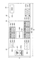
また、制御装置70は、水素貯蔵装置50に貯蔵された水素の貯蔵量に基づいて、水素発生装置40を制御する。このことについて図16を用いて説明する。図16は、本実施の形態による水素システム1の動作の一部を示すフロー図である。   The control device 70 controls the hydrogen generation device 40 based on the amount of hydrogen stored in the hydrogen storage device 50. This will be described with reference to FIG. FIG. 16 is a flowchart showing a part of the operation of the hydrogen system 1 according to the present embodiment.

図16に示すように、まず、制御装置70は、水素貯蔵装置50に貯蔵された水素の貯蔵量が、予め定めた所定値より少ないか否かを判断する(ST1)。この場合、制御装置70に、水素貯蔵装置50の計測機器によって計測された水素の貯蔵量が、データ信号として制御装置70に入力され、入力された貯蔵量に基づいて、制御装置70は上記の判断を行う。   As shown in FIG. 16, first, the control device 70 determines whether or not the amount of hydrogen stored in the hydrogen storage device 50 is less than a predetermined value (ST1). In this case, the storage amount of hydrogen measured by the measuring device of the hydrogen storage device 50 is input to the control device 70 as a data signal to the control device 70. Based on the input storage amount, the control device 70 Make a decision.

続いて、制御装置70は、水素の貯蔵量が当該所定値より少ないと判断した場合、水素発生装置40において水素の製造が実施されるように、水素システム1の各装置を制御する(ST2a)。製造された水素は、水素貯蔵装置50に供給されて貯蔵され、水素貯蔵装置50における水素の貯蔵量が増大し得る。   Subsequently, when it is determined that the amount of hydrogen stored is smaller than the predetermined value, the control device 70 controls each device of the hydrogen system 1 so that hydrogen is produced in the hydrogen generation device 40 (ST2a). . The produced hydrogen is supplied to and stored in the hydrogen storage device 50, and the amount of hydrogen stored in the hydrogen storage device 50 can be increased.

一方、水素の貯蔵量が上記所定値以上である場合、制御装置70は、水素発生装置40において水素の製造が停止するように、水素システム1の各装置を制御する(ST2b)。これにより、水素発生装置40から水素貯蔵装置50への水素の供給が停止する。   On the other hand, when the hydrogen storage amount is equal to or greater than the predetermined value, the control device 70 controls each device of the hydrogen system 1 so that the production of hydrogen is stopped in the hydrogen generation device 40 (ST2b). Thereby, the supply of hydrogen from the hydrogen generator 40 to the hydrogen storage device 50 is stopped.

このようにして、本実施の形態では、水素貯蔵装置50において適正量の水素が容易に貯蔵される。このことにより、燃料電池発電装置60が長期間に渡って自立運転を行うことを可能とし、負荷部3に電力を安定的に供給することができる。   Thus, in this embodiment, an appropriate amount of hydrogen is easily stored in the hydrogen storage device 50. As a result, the fuel cell power generation device 60 can perform a self-sustained operation for a long period of time, and power can be stably supplied to the load unit 3.

このように本実施の形態によれば、第2コンテナ82に収容された水素発生装置40によって水素が製造されて、製造された水素が、第2コンテナ82上に縦積みされた第1コンテナ81に収容された水素貯蔵装置50に貯蔵される。水素貯蔵装置50に貯蔵された水素を用いて、第2コンテナ82に収容された燃料電池発電装置60が発電を行い、負荷部3に供給することができる。このことにより、水素を製造して発電を行い、負荷部3への継続的な電力供給を可能にする水素システム1を構成することができる。また、パワーコンディショナ装置20、水素発生装置40、水素貯蔵装置50および燃料電池発電装置60は、第1コンテナ81または第2コンテナ82に収容されている。このことにより、これらの装置を容易に運搬することができ、水素システム1の設置工事の工期を短縮させることができる。さらに、第1コンテナ81が第2コンテナ82上に縦積みされているため、水素システム1の設置スペースを低減することができる。   As described above, according to the present embodiment, hydrogen is produced by the hydrogen generator 40 housed in the second container 82, and the produced hydrogen is vertically stacked on the second container 82. Stored in the hydrogen storage device 50 housed in Using the hydrogen stored in the hydrogen storage device 50, the fuel cell power generation device 60 accommodated in the second container 82 can generate power and supply it to the load unit 3. As a result, it is possible to configure the hydrogen system 1 that produces power by producing hydrogen and enables continuous power supply to the load section 3. Further, the power conditioner device 20, the hydrogen generator 40, the hydrogen storage device 50, and the fuel cell power generator 60 are accommodated in the first container 81 or the second container 82. Thereby, these devices can be easily transported, and the construction period of the installation work of the hydrogen system 1 can be shortened. Furthermore, since the first container 81 is vertically stacked on the second container 82, the installation space of the hydrogen system 1 can be reduced.

また、本実施の形態によれば、第1コンテナ81の下方に設置された第2コンテナ82に、パワーコンディショナ装置20、水素発生装置40および燃料電池発電装置60が収容されている。このことにより、水素貯蔵装置50が収容された第1コンテナ81よりも重い第2コンテナ82を下側に配置することができ、水素システム用コンテナ組合体80の重心を低くし、安定化を図ることができる。また、パワーコンディショナ装置20、水素発生装置40および燃料電池発電装置60は、水素貯蔵装置50に比べるとメンテナンスの頻度が高いため、メンテナンス作業の効率を向上させる水素システム1を得ることができる。   Further, according to the present embodiment, the power conditioner device 20, the hydrogen generator 40, and the fuel cell power generation device 60 are accommodated in the second container 82 installed below the first container 81. Accordingly, the second container 82 that is heavier than the first container 81 in which the hydrogen storage device 50 is accommodated can be disposed on the lower side, and the center of gravity of the hydrogen system container assembly 80 is lowered to achieve stabilization. be able to. Further, since the power conditioner device 20, the hydrogen generator 40, and the fuel cell power generator 60 are more frequently maintained than the hydrogen storage device 50, the hydrogen system 1 that improves the efficiency of the maintenance work can be obtained.

なお、上述した本実施の形態においては、パワーコンディショナ装置20が蓄電池202を有している例について説明した。しかしながら、このことに限られることはなく、パワーコンディショナ装置20は、蓄電池202を有していなくてもよい。   In addition, in this Embodiment mentioned above, the example in which the power conditioner apparatus 20 has the storage battery 202 was demonstrated. However, the present invention is not limited to this, and the power conditioner device 20 may not include the storage battery 202.

また、上述した本実施の形態においては、水素システム1が貯水装置30を備えている例について説明した。しかしながら、このことに限られることはなく、水素システム1は、貯水装置30を備えていなくてもよい。この場合、水素発生装置40と燃料電池発電装置60のそれぞれに、既設の水道設備から直接的に水が供給されるようにすることが好適である。   Moreover, in this Embodiment mentioned above, the hydrogen system 1 demonstrated the example provided with the water storage apparatus 30. FIG. However, the present invention is not limited to this, and the hydrogen system 1 may not include the water storage device 30. In this case, it is preferable that the hydrogen generator 40 and the fuel cell power generator 60 are each supplied with water directly from the existing water supply equipment.

また、上述した本実施の形態においては、水素貯蔵装置50が水素貯蔵タンク501を含む例について説明した。しかしながら、このことに限られることはなく、水素貯蔵装置50は、液体状態の水素を貯蔵する構成であってもよく、あるいは水素吸蔵合金を用いて水素を貯蔵する構成であってもよい。   Moreover, in this Embodiment mentioned above, the hydrogen storage apparatus 50 demonstrated the example containing the hydrogen storage tank 501. FIG. However, the present invention is not limited to this, and the hydrogen storage device 50 may be configured to store hydrogen in a liquid state, or may be configured to store hydrogen using a hydrogen storage alloy.

また、上述した本実施の形態においては、燃料電池発電装置60が、ラジエータ604を有している例について説明した。しかしながら、このことに限られることはなく、燃料電池発電装置60は、ラジエータ604を有していなくてもよい。   Moreover, in this Embodiment mentioned above, the fuel cell electric power generating apparatus 60 demonstrated the example which has the radiator 604. FIG. However, the present invention is not limited to this, and the fuel cell power generator 60 may not have the radiator 604.

また、上述した本実施の形態においては、水素システム1が電力系統2に連系され、電力系統2から電力が供給可能に構成されている例について説明した。しかしながら、このことに限られることはなく、水素システム1には、電力系統2から電力が供給されないように構成されていてもよい。   Moreover, in this Embodiment mentioned above, the hydrogen system 1 was connected with the electric power grid | system 2, and the example comprised so that electric power could be supplied from the electric power grid | system 2 was demonstrated. However, the present invention is not limited to this, and the hydrogen system 1 may be configured not to be supplied with power from the power system 2.

また、上述した本実施の形態においては、第1コンテナ81に水素貯蔵装置50が収容され、第2コンテナ82に、パワーコンディショナ装置20、水素発生装置40および燃料電池発電装置60が収容されている例について説明した。しかしながら、このことに限られることはない。例えば、第1コンテナ81に、パワーコンディショナ装置20、水素発生装置40、水素貯蔵装置50および燃料電池発電装置60のうちの一つ以上三つ以下の装置が収容され、第2コンテナ82に、その残りの装置が収容されていてもよい。言い換えると、第1コンテナ81に、パワーコンディショナ装置20、水素発生装置40、水素貯蔵装置50および燃料電池発電装置60のうちのいずれかが収容され、その残りが第2コンテナ82内に収容されていてもよい。この場合においても、継続的な電力供給を可能にするシステムの設置工事の工期を短縮させることができるとともに設置スペースを低減することができる。更に言えば、第1コンテナ81に、パワーコンディショナ装置20、水素発生装置40、水素貯蔵装置50および燃料電池発電装置60のうちの少なくとも一つが収容され、第2コンテナ82に、パワーコンディショナ装置20、水素発生装置40、水素貯蔵装置50および燃料電池発電装置60のうちの少なくとも一つが収容されていればよい。この場合においても、継続的な電力供給を可能にするシステムの設置工事の工期を短縮させることができるとともに設置スペースを低減することができる。なお、上述した装置20、40、50、60以外の装置である自然エネルギー発電装置10や、貯水装置30、制御装置70が、第1コンテナ81または第2コンテナ82に収容されていてもよい。すなわち、第1コンテナ81および第2コンテナ82に収容される装置構成は、上述した本実施の形態の例に限られるものではない。   In the above-described embodiment, the hydrogen storage device 50 is accommodated in the first container 81, and the power conditioner device 20, the hydrogen generator 40, and the fuel cell power generator 60 are accommodated in the second container 82. Explained an example. However, the present invention is not limited to this. For example, the first container 81 accommodates one or more of the power conditioner device 20, the hydrogen generator 40, the hydrogen storage device 50, and the fuel cell power generator 60, and the second container 82 contains The remaining devices may be accommodated. In other words, any one of the power conditioner device 20, the hydrogen generator 40, the hydrogen storage device 50, and the fuel cell power generator 60 is accommodated in the first container 81, and the rest is accommodated in the second container 82. It may be. Even in this case, it is possible to shorten the installation period of the system installation work that enables continuous power supply and to reduce the installation space. Furthermore, at least one of the power conditioner device 20, the hydrogen generator 40, the hydrogen storage device 50, and the fuel cell power generator 60 is accommodated in the first container 81, and the power conditioner device is accommodated in the second container 82. 20, at least one of the hydrogen generator 40, the hydrogen storage device 50, and the fuel cell power generator 60 may be accommodated. Even in this case, it is possible to shorten the installation period of the system installation work that enables continuous power supply and to reduce the installation space. Note that the natural energy power generation device 10, the water storage device 30, and the control device 70 other than the devices 20, 40, 50, and 60 described above may be accommodated in the first container 81 or the second container 82. That is, the apparatus configuration accommodated in the first container 81 and the second container 82 is not limited to the example of the present embodiment described above.

(第2の実施の形態)
次に、図17を用いて、第2の実施の形態における水素システム用コンテナ組合体について説明する。
(Second Embodiment)
Next, the container assembly for a hydrogen system in the second embodiment will be described with reference to FIG.

図17に示す第2の実施の形態においては、第1コンテナの上面、および/または、第1コンテナ若しくは第2コンテナの側面に太陽光発電装置が設置されている点が主に異なり、他の構成は、図1乃至図16に示す第1の実施の形態と略同一である。なお、図17において、図1乃至図16に示す第1の実施の形態と同一部分には同一符号を付して詳細な説明は省略する。   The second embodiment shown in FIG. 17 is mainly different in that the photovoltaic power generator is installed on the upper surface of the first container and / or the side surface of the first container or the second container. The configuration is substantially the same as that of the first embodiment shown in FIGS. In FIG. 17, the same parts as those of the first embodiment shown in FIGS. 1 to 16 are denoted by the same reference numerals, and detailed description thereof is omitted.

図17に示すように、本実施の形態においては、第1コンテナ81の上面に、自然エネルギー発電装置10としての太陽光発電装置11の太陽電池パネル11aが設置されている。この太陽電池パネル11aは、図示しない架台を介して第1コンテナ81の上面に取り付けられていてもよい。また、太陽電池パネル11aは、太陽光の採光効率が最も良くなるように、南側を向いて傾斜させることが好適である。   As shown in FIG. 17, in the present embodiment, solar cell panel 11 a of solar power generation device 11 as natural energy power generation device 10 is installed on the upper surface of first container 81. This solar cell panel 11a may be attached to the upper surface of the first container 81 via a gantry (not shown). Moreover, it is suitable for the solar cell panel 11a to incline toward the south side so that the daylighting efficiency of sunlight becomes the best.

また、図17に示すように、第1コンテナ81若しくは第2コンテナ82の正面(側面)に、太陽光発電装置11の他の太陽電池パネル11aが設置されている。この太陽電池パネル11aも、図示しない架台を介して第1コンテナ81および第2コンテナ82のうちの少なくとも一つに取り付けられていてもよい。ここで、コンテナ81、82の正面とは、直方体状のコンテナ81、82の4つの側面のうち、幅寸法が大きい側面であって、太陽光の採光効率が最も良くなる側面を意味するものとして用いている。すなわち、各コンテナ81、82の幅寸法が大きい側面を南側に向けて正面とし、当該正面に太陽電池パネル11aを傾斜させて設置することが好適である。   Moreover, as shown in FIG. 17, the other solar cell panel 11a of the solar power generation device 11 is installed in the front (side surface) of the 1st container 81 or the 2nd container 82. As shown in FIG. This solar cell panel 11a may also be attached to at least one of the first container 81 and the second container 82 via a mount (not shown). Here, the front surface of the containers 81 and 82 is a side surface having a large width dimension among the four side surfaces of the rectangular parallelepiped containers 81 and 82, and means a side surface in which the daylighting efficiency of sunlight is the best. Used. That is, it is preferable to install the container 81, 82 with the side surface having the large width dimension facing the south side and the solar cell panel 11a inclined to the front side.

なお、図17に示すように、第1コンテナ81の上面に太陽電池パネル11aが設置されるとともに、第1コンテナ81若しくは第2コンテナ82の正面に太陽電池パネル11aが設置されていてもよい。この場合、2つの太陽電池パネル11aが自然エネルギー発電装置10を構成する。あるいは、図示しないが、第1コンテナ81の上面、並びに、第1コンテナ81若しくは第2コンテナ82の正面のうちのいずれか一方に太陽電池パネル11aが設置されるようにしてもよい。   As shown in FIG. 17, the solar cell panel 11 a may be installed on the upper surface of the first container 81, and the solar cell panel 11 a may be installed on the front surface of the first container 81 or the second container 82. In this case, the two solar battery panels 11 a constitute the natural energy power generation apparatus 10. Or although not shown in figure, you may make it the solar cell panel 11a install in any one of the upper surface of the 1st container 81, and the front surface of the 1st container 81 or the 2nd container 82. FIG.

このように本実施の形態によれば、太陽光発電装置11の太陽電池パネル11aが第1コンテナ81上に、または第1コンテナ81若しくは第2コンテナ82の正面に設置される。このことにより、水素システム1の設置スペースをより一層低減することができる。また、第1コンテナ81上に太陽電池パネル11aを設置する場合には、周囲の建物などによって太陽光が遮られることを抑制でき、太陽光発電装置11の運転効率を向上させることができる。   Thus, according to this Embodiment, the solar cell panel 11a of the solar power generation device 11 is installed on the 1st container 81 or the front of the 1st container 81 or the 2nd container 82. FIG. Thereby, the installation space of the hydrogen system 1 can be further reduced. Moreover, when installing the solar cell panel 11a on the 1st container 81, it can suppress that sunlight is interrupted | blocked by the surrounding building etc., and can improve the operating efficiency of the solar power generation device 11. FIG.

(第3の実施の形態)
次に、図18を用いて、第3の実施の形態における水素システム用コンテナ組合体について説明する。
(Third embodiment)
Next, the container assembly for a hydrogen system in the third embodiment will be described with reference to FIG.

図18に示す第3の実施の形態においては、第1コンテナと第2コンテナとの間に振動吸収機構が介在されている点が主に異なり、他の構成は、図17に示す第2の実施の形態と略同一である。なお、図18において、図17に示す第2の実施の形態と同一部分には同一符号を付して詳細な説明は省略する。   The third embodiment shown in FIG. 18 is mainly different in that a vibration absorbing mechanism is interposed between the first container and the second container, and the other configuration is the second configuration shown in FIG. This is substantially the same as the embodiment. In FIG. 18, the same parts as those of the second embodiment shown in FIG.

図18に示すように、本実施の形態においては、第1コンテナ81と第2コンテナ82との間に、振動吸収機構83が介在されている。振動吸収機構83としては、例えば、積層ゴムを挙げることができるが、振動を吸収可能であれば、これに限られることはない。   As shown in FIG. 18, in the present embodiment, a vibration absorbing mechanism 83 is interposed between the first container 81 and the second container 82. Examples of the vibration absorbing mechanism 83 include laminated rubber, but are not limited to this as long as vibration can be absorbed.

このように本実施の形態によれば、第1コンテナ81と第2コンテナ82との間に介在された振動吸収機構83により、第1コンテナ81の振動が第2コンテナ82に伝達されることを抑制できるとともに、第2コンテナ82の振動が第1コンテナ81に伝達されることを抑制できる。とりわけ、第1コンテナ81または第2コンテナ82に太陽光発電装置11が設置されている場合には、第2コンテナ82の振動が太陽光発電装置11の太陽電池パネル11aに伝達されることを抑制でき、太陽電池パネル11aとコンテナ81、82との取付信頼性の低下を防止できる。   As described above, according to the present embodiment, the vibration of the first container 81 is transmitted to the second container 82 by the vibration absorbing mechanism 83 interposed between the first container 81 and the second container 82. While being able to suppress, it can suppress that the vibration of the 2nd container 82 is transmitted to the 1st container 81. FIG. In particular, when the solar power generation device 11 is installed in the first container 81 or the second container 82, the vibration of the second container 82 is suppressed from being transmitted to the solar cell panel 11a of the solar power generation device 11. It is possible to prevent a decrease in the mounting reliability between the solar cell panel 11a and the containers 81 and 82.

(第4の実施の形態)
次に、図19を用いて、第4の実施の形態における水素システム用コンテナ組合体について説明する。
(Fourth embodiment)
Next, the hydrogen system container assembly in the fourth embodiment will be described with reference to FIG.

図19に示す第4の実施の形態においては、第2コンテナの側方に第3コンテナが設置され、第3コンテナ上に第4コンテナが縦積みされ、第1コンテナの上面および第4コンテナの上面に、太陽光発電装置が設置されている点が主に異なり、他の構成は、図17に示す第2の実施の形態と略同一である。なお、図19において、図17に示す第2の実施の形態と同一部分には同一符号を付して詳細な説明は省略する。   In the fourth embodiment shown in FIG. 19, the third container is installed on the side of the second container, the fourth container is vertically stacked on the third container, the upper surface of the first container and the fourth container The main difference is that a solar power generation device is installed on the upper surface, and the other configuration is substantially the same as that of the second embodiment shown in FIG. In FIG. 19, the same parts as those of the second embodiment shown in FIG.

図19に示すように、本実施の形態においては、第2コンテナ82の側方(奥側)に第3コンテナ84が設置され、第3コンテナ84上に第4コンテナ85が縦積みされている。第3コンテナ84には、パワーコンディショナ装置20、水素発生装置40、水素貯蔵装置50および燃料電池発電装置60のうちの少なくとも一つが収容され、第4コンテナ85にも、これらの装置20、40、50および60のうちの少なくとも一つが収容されていればよく、第3コンテナ84および第4コンテナ85に収容される装置構成は任意である。   As shown in FIG. 19, in the present embodiment, the third container 84 is installed on the side (back side) of the second container 82, and the fourth container 85 is stacked vertically on the third container 84. . The third container 84 accommodates at least one of the power conditioner device 20, the hydrogen generator 40, the hydrogen storage device 50, and the fuel cell power generator 60, and the fourth container 85 also includes these devices 20, 40. , 50 and 60 may be accommodated, and the device configuration accommodated in the third container 84 and the fourth container 85 is arbitrary.

図19に示すように、第1コンテナ81の上面だけでなく、第4コンテナ85の上面にも、自然エネルギー発電装置10を構成する太陽光発電装置11の太陽電池パネル11aが設置されている。また、図17に示す形態と同様にして、第1コンテナ81若しくは第2コンテナ82の正面(第3コンテナ83若しくは第4コンテナ84の側とは反対側の側面)にも太陽光発電装置11の太陽電池パネル11aが設置されていてもよい。   As shown in FIG. 19, not only the upper surface of the first container 81 but also the upper surface of the fourth container 85 is provided with a solar cell panel 11 a of the solar power generation device 11 constituting the natural energy power generation device 10. Similarly to the embodiment shown in FIG. 17, the solar power generation device 11 is also provided on the front surface of the first container 81 or the second container 82 (the side surface opposite to the third container 83 or the fourth container 84 side). The solar cell panel 11a may be installed.

このように本実施の形態によれば、第2コンテナ82の側方に第3コンテナ84が設置され、第3コンテナ84上に第4コンテナ85が縦積みされている。そして、第1コンテナ81の上面および第4コンテナ85の上面に、太陽光発電装置11の太陽電池パネル11aが設置されている。このことにより、太陽電池パネル11aの個数または表面積を増大させることができ、太陽光発電装置11から出力される電力の出力量を増大させることができる。   Thus, according to the present embodiment, the third container 84 is installed on the side of the second container 82, and the fourth container 85 is stacked vertically on the third container 84. And the solar cell panel 11a of the solar power generation device 11 is installed on the upper surface of the first container 81 and the upper surface of the fourth container 85. As a result, the number or surface area of the solar cell panels 11a can be increased, and the output amount of power output from the solar power generation device 11 can be increased.

(第5の実施の形態)
次に、図20を用いて、第5の実施の形態における水素システム用コンテナ組合体について説明する。
(Fifth embodiment)
Next, a container assembly for a hydrogen system in the fifth embodiment will be described with reference to FIG.

図20に示す第5の実施の形態においては、第2コンテナの側方に傾斜設置用コンテナが設置され、第1コンテナおよび傾斜設置用コンテナに、太陽電池パネルが傾斜するように太陽光発電装置が設置されている点が主に異なり、他の構成は、図1乃至図16に示す第2の実施の形態と略同一である。なお、図20において、図1乃至図16に示す第1の実施の形態と同一部分には同一符号を付して詳細な説明は省略する。   In the fifth embodiment shown in FIG. 20, a photovoltaic power generation apparatus is provided such that an inclined installation container is installed on the side of the second container, and the solar cell panel is inclined on the first container and the inclined installation container. Is mainly different, and other configurations are substantially the same as those of the second embodiment shown in FIGS. In FIG. 20, the same parts as those of the first embodiment shown in FIGS. 1 to 16 are denoted by the same reference numerals, and detailed description thereof is omitted.

図20に示すように、本実施の形態においては、第2コンテナ82の側方(奥側)に第3コンテナ84が設置され、第3コンテナ84上に第4コンテナ85が縦積みされている。第3コンテナ84には、パワーコンディショナ装置20、水素発生装置40、水素貯蔵装置50および燃料電池発電装置60のうちの少なくとも一つが収容され、第4コンテナ85にも、これらの装置20、40、50および60のうちの少なくとも一つが収容されていればよく、第3コンテナ84および第4コンテナ85に収容される装置構成は任意である。   As shown in FIG. 20, in the present embodiment, a third container 84 is installed on the side (back side) of the second container 82, and the fourth container 85 is vertically stacked on the third container 84. . The third container 84 accommodates at least one of the power conditioner device 20, the hydrogen generator 40, the hydrogen storage device 50, and the fuel cell power generator 60, and the fourth container 85 also includes these devices 20, 40. , 50 and 60 may be accommodated, and the device configuration accommodated in the third container 84 and the fourth container 85 is arbitrary.

また、第2コンテナ82の側方(正面側)に傾斜設置用コンテナ86が設置されている。また、第4コンテナ85上に第2の傾斜設置用コンテナ87が縦積みされている。このようにして、各コンテナの長手方向に沿って見たときに、傾斜設置用コンテナ86、第1コンテナ81および第2の傾斜設置用コンテナ87が、階段状に配置されている。傾斜設置用コンテナ86および第2傾斜設置用コンテナ87には、パワーコンディショナ装置20、水素発生装置40、水素貯蔵装置50および燃料電池発電装置60のうちの少なくとも一つが収容されている。   An inclined installation container 86 is installed on the side (front side) of the second container 82. In addition, second inclined installation containers 87 are vertically stacked on the fourth container 85. In this way, when viewed along the longitudinal direction of each container, the inclined installation container 86, the first container 81, and the second inclined installation container 87 are arranged in a staircase pattern. The inclined installation container 86 and the second inclined installation container 87 accommodate at least one of the power conditioner device 20, the hydrogen generator 40, the hydrogen storage device 50, and the fuel cell power generator 60.

第1コンテナ81、傾斜設置用コンテナ86および第2の傾斜設置用コンテナ87に、自然エネルギー発電装置10としての太陽光発電装置11の太陽電池パネル11aが傾斜するように設置されている。この太陽電池パネル11aは、図示しない架台を介して第1コンテナ81、傾斜設置用コンテナ86および第2の傾斜設置用コンテナ87に取り付けられていればよい。このことにより、太陽電池パネル11aを傾斜させた取付を容易に実現することができる。また、各コンテナの幅寸法が大きい側面を南側に向けて正面とし、当該正面に積み重なるように、太陽電池パネル11aを傾斜させて設置することが好適である。   The solar cell panel 11a of the solar power generation device 11 as the natural energy power generation device 10 is installed in the first container 81, the inclined installation container 86, and the second inclined installation container 87 so as to be inclined. The solar cell panel 11a only needs to be attached to the first container 81, the inclined installation container 86, and the second inclined installation container 87 via a gantry (not shown). As a result, it is possible to easily realize the installation in which the solar cell panel 11a is inclined. In addition, it is preferable that the solar cell panel 11a is inclined and installed so that the side surface with the large width dimension of each container is the front side facing the south side, and is stacked on the front surface.

このように本実施の形態によれば、第2コンテナ82の側方に傾斜設置用コンテナ86が設置され、第4コンテナ85上に第2の傾斜設置用コンテナ87が縦積みされている。このことにより、コンテナの長手方向に沿って見たときに、第1コンテナ81、傾斜設置用コンテナ86および第2の傾斜設置用コンテナ87を階段状に配置することができる。このため、太陽光発電装置11の太陽電池パネル11aを、第1コンテナ81、傾斜設置用コンテナ86および第2の傾斜設置用コンテナ87に設置することにより、容易に傾斜させることができるとともに、太陽電池パネル11aの表面積を増大させることができる。この結果、太陽電池パネル11aの採光効率を容易に向上させるとともに電力の出力量を増大させることができる。また、水素システム1の設置スペースを低減することができる。   As described above, according to the present embodiment, the inclined installation container 86 is installed on the side of the second container 82, and the second inclined installation container 87 is vertically stacked on the fourth container 85. Accordingly, the first container 81, the inclined installation container 86, and the second inclined installation container 87 can be arranged in a step shape when viewed along the longitudinal direction of the container. For this reason, while installing the solar cell panel 11a of the solar power generation device 11 in the first container 81, the inclined installation container 86, and the second inclined installation container 87, the solar panel 11a can be easily inclined, The surface area of the battery panel 11a can be increased. As a result, it is possible to easily improve the daylighting efficiency of the solar cell panel 11a and increase the output amount of power. Moreover, the installation space of the hydrogen system 1 can be reduced.

なお、上述した本実施の形態においては、第3コンテナ84および第4コンテナ85が設置され、第4コンテナ85上に第2の傾斜設置用コンテナ87が縦積みされ、太陽光発電装置11が、第1コンテナ81、傾斜設置用コンテナ86および第2の傾斜設置用コンテナ87に設置されている例について説明した。しかしながら、このことに限られることはなく、第3コンテナ84、第4コンテナ85および第2の傾斜設置用コンテナ87が設置されることなく、太陽光発電装置11が、第1コンテナ81および傾斜設置用コンテナ86に設置されて、太陽電池パネル11aを傾斜させるようにしてもよい。この場合においても、コンテナの長手方向に沿って見たときに、第1コンテナ81および傾斜設置用コンテナ86が階段状に配置され、太陽電池パネル11aを容易に傾斜させることができる。   In the present embodiment described above, the third container 84 and the fourth container 85 are installed, the second inclined installation container 87 is vertically stacked on the fourth container 85, and the photovoltaic power generation apparatus 11 is The example installed in the 1st container 81, the container 86 for inclination installation, and the container 87 for 2nd inclination installation was demonstrated. However, the present invention is not limited to this, and the solar power generation apparatus 11 is installed in the first container 81 and the inclined installation without the third container 84, the fourth container 85, and the second inclined installation container 87 installed. The solar cell panel 11a may be inclined by being installed in the container 86 for use. Also in this case, when viewed along the longitudinal direction of the container, the first container 81 and the inclined installation container 86 are arranged in a step shape, and the solar cell panel 11a can be easily inclined.

(第6の実施の形態)
次に、図21を用いて、第6の実施の形態における水素システム用コンテナ組合体について説明する。
(Sixth embodiment)
Next, a container assembly for a hydrogen system according to the sixth embodiment will be described with reference to FIG.

図21に示す第6の実施の形態においては、第1コンテナに収容された装置と第2コンテナに収容された装置とが同一であり、第3コンテナに収容された装置と第4コンテナに収容された装置とが同一である点が主に異なり、他の構成は、図19に示す第4の実施の形態と略同一である。なお、図21において、図19に示す第4の実施の形態と同一部分には同一符号を付して詳細な説明は省略する。   In the sixth embodiment shown in FIG. 21, the device accommodated in the first container is the same as the device accommodated in the second container, and accommodated in the device accommodated in the third container and the fourth container. The main difference is that the apparatus is the same as that of the fourth embodiment, and the other configuration is substantially the same as that of the fourth embodiment shown in FIG. In FIG. 21, the same parts as those in the fourth embodiment shown in FIG.

図21に示すように、本実施の形態においては、第1コンテナ81に収容された装置と第2コンテナ82に収容された装置とが同一である。すなわち、第1コンテナ81および第2コンテナ82には、パワーコンディショナ装置20、水素発生装置40および燃料電池発電装置60がそれぞれ収容されている。   As shown in FIG. 21, in the present embodiment, the apparatus accommodated in the first container 81 and the apparatus accommodated in the second container 82 are the same. That is, the first container 81 and the second container 82 accommodate the power conditioner device 20, the hydrogen generator 40, and the fuel cell power generator 60, respectively.

また、第3コンテナ84に収容された装置と第4コンテナ85に収容された装置とが同一である。すなわち、第3コンテナ84および第4コンテナ85には、水素貯蔵装置50がそれぞれ収容されている。   Further, the device housed in the third container 84 and the device housed in the fourth container 85 are the same. That is, the hydrogen storage device 50 is accommodated in the third container 84 and the fourth container 85, respectively.

このようにして、本実施の形態による水素システム1は、2つのパワーコンディショナ装置20、2つの水素発生装置40、2つの水素貯蔵装置50、および2つの燃料電池発電装置60を備えている。なお、図21に示す形態においては、太陽光発電装置11は、コンテナに設置されていないが、図19に示す第4の実施の形態のように、太陽光発電装置11が、コンテナに設置されていてもよい。   As described above, the hydrogen system 1 according to the present embodiment includes the two power conditioner devices 20, the two hydrogen generation devices 40, the two hydrogen storage devices 50, and the two fuel cell power generation devices 60. In the configuration shown in FIG. 21, the solar power generation device 11 is not installed in the container. However, as in the fourth embodiment shown in FIG. 19, the solar power generation device 11 is installed in the container. It may be.

このように本実施の形態によれば、パワーコンディショナ装置20、水素発生装置40、水素貯蔵装置50および燃料電池発電装置60がそれぞれ2つずつ設けられている。このことにより、蓄電量を増大させ、水素の製造能力を増大させ、水素の貯蔵容量を増大させ、水素による発電量を増大させることができる。更には、温水の生成量を増大させることもできる。また、同一の装置を収容したコンテナ同士が縦積みされているため、同一の装置同士での配管や配線等の接続を容易に行うことができる。   Thus, according to the present embodiment, two each of the power conditioner device 20, the hydrogen generator 40, the hydrogen storage device 50, and the fuel cell power generator 60 are provided. As a result, the amount of electricity stored can be increased, the production capacity of hydrogen can be increased, the storage capacity of hydrogen can be increased, and the amount of power generated by hydrogen can be increased. Furthermore, the amount of hot water produced can be increased. Moreover, since containers containing the same device are stacked vertically, it is possible to easily connect piping, wiring, and the like between the same devices.

なお、上述した本実施の形態においては、第1コンテナ81および第2コンテナ82に、パワーコンディショナ装置20、水素発生装置40および燃料電池発電装置60がそれぞれ収容されるとともに、第3コンテナ84および第4コンテナ85に、水素貯蔵装置50がそれぞれ収容されている例について説明した。しかしながら、このことに限られることはなく、第1コンテナ81に収容される装置と第2コンテナ82に収容される装置とが同一であれば、第1コンテナ81および第2コンテナ82に収容される装置は、パワーコンディショナ装置20、水素発生装置40、水素貯蔵装置50および燃料電池発電装置60のうちの少なくとも一つであればよい。同様に、第3コンテナ84に収容される装置と第4コンテナ85に収容される装置とが同一であれば、第3コンテナ84および第4コンテナ85に収容される装置は、パワーコンディショナ装置20、水素発生装置40、水素貯蔵装置50および燃料電池発電装置60のうちの少なくとも一つであればよい。   In the present embodiment described above, the first container 81 and the second container 82 accommodate the power conditioner device 20, the hydrogen generator 40, and the fuel cell power generator 60, respectively, and the third container 84 and The example in which the hydrogen storage device 50 is accommodated in the fourth container 85 has been described. However, the present invention is not limited to this. If the apparatus accommodated in the first container 81 and the apparatus accommodated in the second container 82 are the same, the apparatus is accommodated in the first container 81 and the second container 82. The device may be at least one of the power conditioner device 20, the hydrogen generator 40, the hydrogen storage device 50, and the fuel cell power generator 60. Similarly, if the device accommodated in the third container 84 and the device accommodated in the fourth container 85 are the same, the device accommodated in the third container 84 and the fourth container 85 is the power conditioner device 20. Any one of the hydrogen generator 40, the hydrogen storage device 50, and the fuel cell power generator 60 may be used.

(第7の実施の形態)
次に、図22を用いて、第7の実施の形態における水素システム用コンテナ組合体について説明する。
(Seventh embodiment)
Next, the container assembly for a hydrogen system in the seventh embodiment will be described with reference to FIG.

図22に示す第7の実施の形態においては、互いに異なる装置が収容されて縦積みされた2つのコンテナによりそれぞれ構成される2つのセットが並設されている点が主に異なり、他の構成は、図21に示す第6の実施の形態と略同一である。なお、図22において、図21に示す第6の実施の形態と同一部分には同一符号を付して詳細な説明は省略する。   The seventh embodiment shown in FIG. 22 is mainly different in that two sets each constituted by two containers that are housed in different directions and housed vertically are arranged in parallel. Is substantially the same as the sixth embodiment shown in FIG. In FIG. 22, the same parts as those of the sixth embodiment shown in FIG.

図22に示すように、本実施の形態においては、第1コンテナ81に収容された装置と第4コンテナ85に収容された装置とが同一である。すなわち、第1コンテナ81および第4コンテナ85には、水素貯蔵装置50がそれぞれ収容されている。   As shown in FIG. 22, in the present embodiment, the device housed in the first container 81 and the device housed in the fourth container 85 are the same. That is, the hydrogen storage device 50 is accommodated in the first container 81 and the fourth container 85, respectively.

また、第2コンテナ82に収容された装置と第3コンテナ84に収容された装置とが同一である。すなわち、第2コンテナ82および第3コンテナ84には、パワーコンディショナ装置20、水素発生装置40および燃料電池発電装置60がそれぞれ収容されている。   Further, the device accommodated in the second container 82 and the device accommodated in the third container 84 are the same. That is, in the second container 82 and the third container 84, the power conditioner device 20, the hydrogen generator 40, and the fuel cell power generator 60 are accommodated, respectively.

このようにして、本実施の形態による水素システム1においては、互いに異なる装置が収容されて縦積みされた第1コンテナ81および第2コンテナ82により構成されたセットと、同様にして互いに異なる装置が収容されて縦積みされた第3コンテナ84および第4コンテナ85により構成されたセットが、並設されている。   In this way, in the hydrogen system 1 according to the present embodiment, different sets of apparatuses are housed in the same manner as the set constituted by the first container 81 and the second container 82 that are housed and stacked vertically. A set constituted by the third container 84 and the fourth container 85 accommodated and vertically stacked is arranged in parallel.

このように本実施の形態によれば、互いに異なる装置が収容されて縦積みされた2つのコンテナ81、82により構成されるセットと、同様にして縦積みされた2つのコンテナ84、85により構成されるセットが、並設されている。このことにより、負荷部3での電力の需要のピークや大きさ、また自然エネルギー発電装置10の発電能力に合わせて、第3コンテナ84および第4コンテナ85を、第1コンテナ81および第2コンテナ82に並設したり、あるいは、他の水素システム1に容易に移設させたりすることができる。このため、水素システム1の状況の変化に応じて、装置構成を柔軟に変更することができ、効率の良い運転を行うことができる。また、第1コンテナ81と第2コンテナ82の装置構成と、第3コンテナ84と第4コンテナ85の装置構成が同一であるため、水素貯蔵量や発電量を同じ割合で変更することができるという利点もある。   As described above, according to the present embodiment, a set including two containers 81 and 82 that are vertically stacked with different devices accommodated therein, and includes two containers 84 and 85 that are similarly stacked vertically. The set to be done is arranged side by side. As a result, the third container 84 and the fourth container 85 are replaced with the first container 81 and the second container in accordance with the peak and size of the power demand at the load section 3 and the power generation capacity of the natural energy power generation apparatus 10. 82 can be juxtaposed with each other, or can be easily transferred to another hydrogen system 1. For this reason, according to the change of the condition of the hydrogen system 1, an apparatus structure can be changed flexibly and an efficient driving | operation can be performed. Moreover, since the apparatus configuration of the first container 81 and the second container 82 and the apparatus configuration of the third container 84 and the fourth container 85 are the same, the hydrogen storage amount and the power generation amount can be changed at the same rate. There are also advantages.

なお、上述した本実施の形態においては、第1コンテナ81および第4コンテナ85に、水素貯蔵装置50がそれぞれ収容されるとともに、第2コンテナ82および第3コンテナ84に、パワーコンディショナ装置20、水素発生装置40および燃料電池発電装置60がそれぞれ収容されている例について説明した。しかしながら、このことに限られることはなく、第1コンテナ81に収容される装置と第4コンテナ85に収容される装置とが同一であれば、第1コンテナ81および第4コンテナ85に収容される装置は、パワーコンディショナ装置20、水素発生装置40、水素貯蔵装置50および燃料電池発電装置60のうちの少なくとも一つであればよい。同様に、第2コンテナ82に収容される装置と第3コンテナ84に収容される装置とが同一であれば、第2コンテナ82および第3コンテナ84に収容される装置は、パワーコンディショナ装置20、水素発生装置40、水素貯蔵装置50および燃料電池発電装置60のうちの少なくとも一つであればよい。   In the present embodiment described above, the hydrogen storage device 50 is accommodated in the first container 81 and the fourth container 85, respectively, and the power conditioner device 20, the second container 82 and the third container 84, The example in which the hydrogen generator 40 and the fuel cell power generator 60 are accommodated has been described. However, the present invention is not limited to this. If the device accommodated in the first container 81 and the device accommodated in the fourth container 85 are the same, the device is accommodated in the first container 81 and the fourth container 85. The device may be at least one of the power conditioner device 20, the hydrogen generator 40, the hydrogen storage device 50, and the fuel cell power generator 60. Similarly, if the device accommodated in the second container 82 and the device accommodated in the third container 84 are the same, the device accommodated in the second container 82 and the third container 84 is the power conditioner device 20. Any one of the hydrogen generator 40, the hydrogen storage device 50, and the fuel cell power generator 60 may be used.

本発明のいくつかの実施形態を説明したが、これらの実施形態は、例として提示したものであり、発明の範囲を限定することは意図していない。これら新規な実施形態は、その他の様々な形態で実施されることが可能であり、発明の要旨を逸脱しない範囲で、種々の省略、置き換え、変更を行うことができる。これら実施形態やその変形は、発明の範囲や要旨に含まれるとともに、特許請求の範囲に記載された発明とその均等の範囲に含まれる。また、当然のことながら、本発明の要旨の範囲内で、これらの実施の形態を、部分的に適宜組み合わせることも可能である。   Although several embodiments of the present invention have been described, these embodiments are presented by way of example and are not intended to limit the scope of the invention. These novel embodiments can be implemented in various other forms, and various omissions, replacements, and changes can be made without departing from the scope of the invention. These embodiments and modifications thereof are included in the scope and gist of the invention, and are included in the invention described in the claims and the equivalents thereof. Moreover, as a matter of course, these embodiments can be partially combined as appropriate within the scope of the present invention.

1 水素システム
11a 太陽電池パネル
20 パワーコンディショナ装置
40 水素発生装置
50 水素貯蔵装置
60 燃料電池発電装置
80 水素システム用コンテナ組合体
81 第1コンテナ
82 第2コンテナ
83 振動吸収機構
84 第3コンテナ
85 第4コンテナ
86 傾斜設置用コンテナ
DESCRIPTION OF SYMBOLS 1 Hydrogen system 11a Solar cell panel 20 Power conditioner apparatus 40 Hydrogen generating apparatus 50 Hydrogen storage apparatus 60 Fuel cell power generation apparatus 80 Container assembly 81 for hydrogen systems 1st container 82 2nd container 83 Vibration absorption mechanism 84 3rd container 85 1st 4 container 86 Inclined container

Claims (12)

水素を発生させる水素発生装置、前記水素発生装置により発生した水素を貯蔵する水素貯蔵装置、前記水素貯蔵装置に貯蔵された水素を用いて発電を行う燃料電池発電装置、および前記水素発生装置に供給される電力を調整する電力調整装置のうちの少なくとも一つが収容された第1コンテナと、
前記水素発生装置、前記水素貯蔵装置、前記燃料電池発電装置、および前記電力調整装置のうちの少なくとも一つが収容された第2コンテナと、を備え、
前記第1コンテナは、前記第2コンテナ上に縦積みされていることを特徴とする水素システム用コンテナ組合体。
A hydrogen generator for generating hydrogen, a hydrogen storage device for storing hydrogen generated by the hydrogen generator, a fuel cell power generator for generating power using hydrogen stored in the hydrogen storage device, and a supply to the hydrogen generator A first container in which at least one of the power adjustment devices for adjusting the power to be stored is accommodated;
A second container in which at least one of the hydrogen generation device, the hydrogen storage device, the fuel cell power generation device, and the power adjustment device is accommodated, and
A container assembly for a hydrogen system, wherein the first container is stacked vertically on the second container.
前記第1コンテナに、前記水素発生装置、前記水素貯蔵装置、前記燃料電池発電装置、および前記電力調整装置の一つ以上三つ以下が収容され、
前記第2コンテナに、前記水素発生装置、前記水素貯蔵装置、前記燃料電池発電装置、および前記電力調整装置の残りが収容されていることを特徴とする請求項1に記載の水素システム用コンテナ組合体。
One or more and three or less of the hydrogen generation device, the hydrogen storage device, the fuel cell power generation device, and the power adjustment device are accommodated in the first container,
2. The hydrogen system container combination according to claim 1, wherein the second container accommodates the hydrogen generation device, the hydrogen storage device, the fuel cell power generation device, and the remainder of the power adjustment device. body.
前記第1コンテナに、前記水素貯蔵装置が収容され、
前記第2コンテナに、前記水素発生装置、前記燃料電池発電装置、および前記電力調整装置が収容されていることを特徴とする請求項1または2に記載の水素システム用コンテナ組合体。
The hydrogen storage device is accommodated in the first container,
3. The hydrogen system container assembly according to claim 1, wherein the hydrogen generation device, the fuel cell power generation device, and the power adjustment device are accommodated in the second container. 4.
前記第1コンテナと前記第2コンテナとの間に振動吸収機構が介在されていることを特徴とする請求項1乃至3のいずれか一項に記載の水素システム用コンテナ組合体。   The container assembly for a hydrogen system according to any one of claims 1 to 3, wherein a vibration absorption mechanism is interposed between the first container and the second container. 前記第1コンテナの上面、および/または、前記第1コンテナ若しくは前記第2コンテナの側面に、太陽電池パネルが設置されていることを特徴とする請求項1乃至4のいずれか一項に記載の水素システム用コンテナ組合体。   The solar cell panel is installed in the upper surface of the said 1st container, and / or the side surface of the said 1st container or the said 2nd container, The Claim 1 thru | or 4 characterized by the above-mentioned. Container assembly for hydrogen systems. 前記第2コンテナの側方に設置された第3コンテナと、
前記第3コンテナ上に縦積みされた第4コンテナと、を更に備え、
前記第3コンテナに、前記水素発生装置、前記水素貯蔵装置、前記燃料電池発電装置、および前記電力調整装置のうちの少なくとも一つが収容され、
前記第4コンテナに、前記水素発生装置、前記水素貯蔵装置、前記燃料電池発電装置、および前記電力調整装置のうちの少なくとも一つが収容され、
前記第1コンテナの上面および前記第4コンテナの上面に、太陽電池パネルが設置されていることを特徴とする請求項1乃至4のいずれか一項に記載の水素システム用コンテナ組合体。
A third container installed on the side of the second container;
A fourth container vertically stacked on the third container,
In the third container, at least one of the hydrogen generation device, the hydrogen storage device, the fuel cell power generation device, and the power adjustment device is accommodated,
At least one of the hydrogen generation device, the hydrogen storage device, the fuel cell power generation device, and the power adjustment device is accommodated in the fourth container,
The solar cell panel is installed in the upper surface of the said 1st container, and the upper surface of the said 4th container, The container assembly for hydrogen systems as described in any one of the Claims 1 thru | or 4 characterized by the above-mentioned.
前記第1コンテナ若しくは前記第2コンテナにおける前記第3コンテナの側とは反対側の側面に、他の太陽電池パネルが設置されていることを特徴とする請求項6に記載の水素システム用コンテナ組合体。   7. The hydrogen system container combination according to claim 6, wherein another solar cell panel is installed on a side surface of the first container or the second container opposite to the third container. body. 前記第2コンテナの側方に設置された傾斜設置用コンテナと、
前記傾斜設置用コンテナに、前記水素発生装置、前記水素貯蔵装置、前記燃料電池発電装置、および前記電力調整装置のうちの少なくとも一つが収容され、
前記第1コンテナおよび前記傾斜設置用コンテナに、太陽電池パネルが傾斜するように設置されていることを特徴とする請求項1乃至4のいずれか一項に記載の水素システム用コンテナ組合体。
A container for inclined installation installed on the side of the second container;
At least one of the hydrogen generation device, the hydrogen storage device, the fuel cell power generation device, and the power adjustment device is accommodated in the inclined installation container,
The container assembly for a hydrogen system according to any one of claims 1 to 4, wherein a solar cell panel is installed on the first container and the inclined installation container so as to be inclined.
前記第2コンテナの側方に設置された第3コンテナと、
前記第3コンテナ上に縦積みされた第4コンテナと、を更に備え、
前記第3コンテナに、前記水素発生装置、前記水素貯蔵装置、前記燃料電池発電装置、および前記電力調整装置のうちの少なくとも一つが収容され、
前記第4コンテナに、前記水素発生装置、前記水素貯蔵装置、前記燃料電池発電装置、および前記電力調整装置のうちの少なくとも一つが収容され、
前記第1コンテナに収容された装置と前記第2コンテナに収容された装置とが同一であり、
前記第3コンテナに収容された装置と前記第4コンテナに収容された装置とが同一であることを特徴とする請求項1に記載の水素システム用コンテナ組合体。
A third container installed on the side of the second container;
A fourth container vertically stacked on the third container,
In the third container, at least one of the hydrogen generation device, the hydrogen storage device, the fuel cell power generation device, and the power adjustment device is accommodated,
At least one of the hydrogen generation device, the hydrogen storage device, the fuel cell power generation device, and the power adjustment device is accommodated in the fourth container,
The device housed in the first container and the device housed in the second container are the same,
2. The hydrogen system container assembly according to claim 1, wherein the apparatus accommodated in the third container and the apparatus accommodated in the fourth container are the same.
前記第2コンテナの側方に設置された第3コンテナと、
前記第3コンテナ上に縦積みされた第4コンテナと、を更に備え、
前記第3コンテナに、前記水素発生装置、前記水素貯蔵装置、前記燃料電池発電装置、および前記電力調整装置のうちの少なくとも一つが収容され、
前記第4コンテナに、前記水素発生装置、前記水素貯蔵装置、前記燃料電池発電装置、および前記電力調整装置のうちの少なくとも一つが収容され、
前記第1コンテナに収容された装置と前記第4コンテナに収容された装置とが同一であり、
前記第2コンテナに収容された装置と前記第3コンテナに収容された装置とが同一であることを特徴とする請求項1に記載の水素システム用コンテナ組合体。
A third container installed on the side of the second container;
A fourth container vertically stacked on the third container,
In the third container, at least one of the hydrogen generation device, the hydrogen storage device, the fuel cell power generation device, and the power adjustment device is accommodated,
At least one of the hydrogen generation device, the hydrogen storage device, the fuel cell power generation device, and the power adjustment device is accommodated in the fourth container,
The device housed in the first container and the device housed in the fourth container are the same,
2. The hydrogen system container assembly according to claim 1, wherein the device housed in the second container and the device housed in the third container are the same.
前記電力調整装置は、蓄電池を含み、
前記蓄電池は、前記燃料電池発電装置で発電された電力を蓄電するように構成されていることを特徴とする請求項1乃至10のいずれか一項に記載の水素システム用コンテナ組合体。
The power adjustment device includes a storage battery,
The container assembly for a hydrogen system according to any one of claims 1 to 10, wherein the storage battery is configured to store electric power generated by the fuel cell power generation device.
前記第1コンテナおよび前記第2コンテナは、規格化された運搬可能な大きさをそれぞれ有していることを特徴とする請求項1乃至5のいずれか一項に記載の水素システム用コンテナ組合体。   The container assembly for a hydrogen system according to any one of claims 1 to 5, wherein the first container and the second container each have a standardized transportable size. .
JP2015122164A 2015-06-17 2015-06-17 Container assembly for hydrogen system Active JP6058746B1 (en)

Priority Applications (2)

Application Number Priority Date Filing Date Title
JP2015122164A JP6058746B1 (en) 2015-06-17 2015-06-17 Container assembly for hydrogen system
PCT/JP2015/075120 WO2016203660A1 (en) 2015-06-17 2015-09-03 Container assembly for hydrogen system

Applications Claiming Priority (1)

Application Number Priority Date Filing Date Title
JP2015122164A JP6058746B1 (en) 2015-06-17 2015-06-17 Container assembly for hydrogen system

Publications (2)

Publication Number Publication Date
JP6058746B1 JP6058746B1 (en) 2017-01-11
JP2017010646A true JP2017010646A (en) 2017-01-12

Family

ID=57545252

Family Applications (1)

Application Number Title Priority Date Filing Date
JP2015122164A Active JP6058746B1 (en) 2015-06-17 2015-06-17 Container assembly for hydrogen system

Country Status (2)

Country Link
JP (1) JP6058746B1 (en)
WO (1) WO2016203660A1 (en)

Cited By (3)

* Cited by examiner, † Cited by third party
Publication number Priority date Publication date Assignee Title
JP2018147603A (en) * 2017-03-01 2018-09-20 ブラザー工業株式会社 Power supply system
JP2019200839A (en) * 2018-05-14 2019-11-21 グローバル・リンク株式会社 Power generation system
JP7304350B2 (en) 2017-12-15 2023-07-06 ブルーム エネルギー コーポレイション Stackable fuel cell generator configuration with common inlet plenum and common outlet plenum

Citations (6)

* Cited by examiner, † Cited by third party
Publication number Priority date Publication date Assignee Title
JP2001035503A (en) * 1999-07-27 2001-02-09 Sanyo Denki Co Ltd Mobile power source vehicle
JP2001329505A (en) * 2000-05-19 2001-11-30 Mitsubishi Heavy Ind Ltd Snow melting method and snow melting system
JP2003082486A (en) * 2001-09-13 2003-03-19 Sony Corp Gaseous hydrogen producing and filling device, and electrochemical device
JP2007005280A (en) * 2004-12-28 2007-01-11 Gs Yuasa Corporation:Kk Fuel cell generator
US7966945B1 (en) * 2008-08-05 2011-06-28 Bnsf Railway Company Isolation and support structures for hydrogen hybrid locomotives and hydrogen hybrid locomotives using the same
US20130344407A1 (en) * 2012-06-25 2013-12-26 Eveready Battery Company, Inc. Hydrogen Generator and Method of Controlling Reaction

Patent Citations (6)

* Cited by examiner, † Cited by third party
Publication number Priority date Publication date Assignee Title
JP2001035503A (en) * 1999-07-27 2001-02-09 Sanyo Denki Co Ltd Mobile power source vehicle
JP2001329505A (en) * 2000-05-19 2001-11-30 Mitsubishi Heavy Ind Ltd Snow melting method and snow melting system
JP2003082486A (en) * 2001-09-13 2003-03-19 Sony Corp Gaseous hydrogen producing and filling device, and electrochemical device
JP2007005280A (en) * 2004-12-28 2007-01-11 Gs Yuasa Corporation:Kk Fuel cell generator
US7966945B1 (en) * 2008-08-05 2011-06-28 Bnsf Railway Company Isolation and support structures for hydrogen hybrid locomotives and hydrogen hybrid locomotives using the same
US20130344407A1 (en) * 2012-06-25 2013-12-26 Eveready Battery Company, Inc. Hydrogen Generator and Method of Controlling Reaction

Cited By (3)

* Cited by examiner, † Cited by third party
Publication number Priority date Publication date Assignee Title
JP2018147603A (en) * 2017-03-01 2018-09-20 ブラザー工業株式会社 Power supply system
JP7304350B2 (en) 2017-12-15 2023-07-06 ブルーム エネルギー コーポレイション Stackable fuel cell generator configuration with common inlet plenum and common outlet plenum
JP2019200839A (en) * 2018-05-14 2019-11-21 グローバル・リンク株式会社 Power generation system

Also Published As

Publication number Publication date
JP6058746B1 (en) 2017-01-11
WO2016203660A1 (en) 2016-12-22

Similar Documents

Publication Publication Date Title
JP6005503B2 (en) Hydrogen power supply system
JP6304008B2 (en) Power supply system
US20130234521A1 (en) Method and device for multifunctional power conversion employing a charging device and having reactive power control
EP3018787B1 (en) Microgrid control device and control method therefor
US20170237260A1 (en) Energy storage system and management method thereof
US20120068661A1 (en) Transportable electricity generation unit and method for generating electricity using said unit
JP5897501B2 (en) Power supply system
EP3447281B1 (en) Movable, autonomous, scalable, self-deployable, monitorable, remotely reprogrammable system for generating electrical energy
JP6058746B1 (en) Container assembly for hydrogen system
JP7286071B2 (en) Hydrogen supply system and hydrogen supply method
JP2014131369A (en) Power control system
JP6802694B2 (en) Power supply stabilization system and renewable energy power generation system
Troncoso et al. Off-grid test results of a solar-powered hydrogen refuelling station for fuel cell powered Unmanned Aerial Vehicles
JP2015220889A (en) Power supply system
US20220267917A1 (en) System for producing hydrogen from renewable energy and control method thereof
WO2016075725A1 (en) Power supply system
US11271230B2 (en) Method for electrical supply of an apparatus by an autonomous hybrid station
Atmaja et al. Fuel saving on diesel genset using PV/battery spike cutting in remote area microgrid
KR101077880B1 (en) emergency power source supply system using multiple power generation
WO2016132406A1 (en) Power supply system
CN209545170U (en) One kind storing up the self-powered storehouse formula energy-storage system of complementary micro-capacitance sensor based on light
KR101644873B1 (en) Electric power transport system and method for transport of electric power using the same
Othman et al. A new design of a hydrogen fueling station powered by renewable energy sources
JP2010098797A (en) Solar light generating system
CN218102600U (en) Zero-carbon industrial park management system considering source storage and load complementation

Legal Events

Date Code Title Description
TRDD Decision of grant or rejection written
A01 Written decision to grant a patent or to grant a registration (utility model)

Free format text: JAPANESE INTERMEDIATE CODE: A01

Effective date: 20161108

A61 First payment of annual fees (during grant procedure)

Free format text: JAPANESE INTERMEDIATE CODE: A61

Effective date: 20161207

R151 Written notification of patent or utility model registration

Ref document number: 6058746

Country of ref document: JP

Free format text: JAPANESE INTERMEDIATE CODE: R151