JP2016533139A - Cyclic prefix with low overhead and extended duration for LTE broadcast - Google Patents
Cyclic prefix with low overhead and extended duration for LTE broadcast Download PDFInfo
- Publication number
- JP2016533139A JP2016533139A JP2016542066A JP2016542066A JP2016533139A JP 2016533139 A JP2016533139 A JP 2016533139A JP 2016542066 A JP2016542066 A JP 2016542066A JP 2016542066 A JP2016542066 A JP 2016542066A JP 2016533139 A JP2016533139 A JP 2016533139A
- Authority
- JP
- Japan
- Prior art keywords
- cyclic prefix
- duration
- carriers
- integer
- overhead
- Prior art date
- Legal status (The legal status is an assumption and is not a legal conclusion. Google has not performed a legal analysis and makes no representation as to the accuracy of the status listed.)
- Pending
Links
Images


Classifications
-
- H—ELECTRICITY
- H04—ELECTRIC COMMUNICATION TECHNIQUE
- H04L—TRANSMISSION OF DIGITAL INFORMATION, e.g. TELEGRAPHIC COMMUNICATION
- H04L27/00—Modulated-carrier systems
- H04L27/26—Systems using multi-frequency codes
- H04L27/2601—Multicarrier modulation systems
- H04L27/2602—Signal structure
- H04L27/2605—Symbol extensions, e.g. Zero Tail, Unique Word [UW]
- H04L27/2607—Cyclic extensions
-
- H—ELECTRICITY
- H04—ELECTRIC COMMUNICATION TECHNIQUE
- H04L—TRANSMISSION OF DIGITAL INFORMATION, e.g. TELEGRAPHIC COMMUNICATION
- H04L1/00—Arrangements for detecting or preventing errors in the information received
- H04L1/12—Arrangements for detecting or preventing errors in the information received by using return channel
- H04L1/16—Arrangements for detecting or preventing errors in the information received by using return channel in which the return channel carries supervisory signals, e.g. repetition request signals
- H04L1/18—Automatic repetition systems, e.g. Van Duuren systems
- H04L1/1812—Hybrid protocols; Hybrid automatic repeat request [HARQ]
-
- H—ELECTRICITY
- H04—ELECTRIC COMMUNICATION TECHNIQUE
- H04L—TRANSMISSION OF DIGITAL INFORMATION, e.g. TELEGRAPHIC COMMUNICATION
- H04L5/00—Arrangements affording multiple use of the transmission path
- H04L5/003—Arrangements for allocating sub-channels of the transmission path
- H04L5/0037—Inter-user or inter-terminal allocation
-
- H—ELECTRICITY
- H04—ELECTRIC COMMUNICATION TECHNIQUE
- H04L—TRANSMISSION OF DIGITAL INFORMATION, e.g. TELEGRAPHIC COMMUNICATION
- H04L5/00—Arrangements affording multiple use of the transmission path
- H04L5/003—Arrangements for allocating sub-channels of the transmission path
- H04L5/0058—Allocation criteria
- H04L5/0069—Allocation based on distance or geographical location
-
- H—ELECTRICITY
- H04—ELECTRIC COMMUNICATION TECHNIQUE
- H04W—WIRELESS COMMUNICATION NETWORKS
- H04W72/00—Local resource management
- H04W72/30—Resource management for broadcast services
Abstract
オーバーヘッドが小さく継続時間が拡張されたサイクリックプレフィックスが開示され、ここで、公称の25リソースブロック(RB)当たりに300キャリアの規定を越えるキャリアの整数倍のシーケンスが、サイクリックプレフィックスオーバーヘッドを規範的な20%よりも下方へ低減させるように選択される。継続時間の集合が、次いで、シンボル継続時間および継続時間が拡張されたサイクリックプレフィックスの結合された継続時間を、各RBに対するキャリアとして整数とする、キャリアのそのような各整数倍のシーケンスと関連して形成される。A cyclic prefix with low overhead and extended duration is disclosed, where a sequence of integer multiples of more than 300 carriers per nominal 25 resource block (RB) is normative for cyclic prefix overhead Is selected to be reduced below 20%. A set of durations is then associated with each such integer multiple sequence of carriers, where the combined duration of the symbol duration and extended cyclic prefix is an integer as the carrier for each RB Formed.
Description
関連出願の相互参照
本出願は、その全体が参照により本明細書に明確に組み込まれる、2013年9月13日に出願された「EXTENDED DURATION CYCLIC PREFIX WITH LOW OVERHEAD FOR LTE BROADCAST」と題する米国仮特許出願第61/877,864号、2013年9月27日に出願された「EXTENDED DURATION CYCLIC PREFIX WITH LOW OVERHEAD FOR LTE BROADCAST」と題する米国仮特許出願第61/883,820号、および2014年9月9日に出願された「EXTENDED DURATION CYCLIC PREFIX WITH LOW OVERHEAD FOR LTE BROADCAST」と題する米国実用特許出願第14/480,897号の利益を主張するものである。
This application is a U.S. provisional patent entitled `` EXTENDED DURATION CYCLIC PREFIX WITH LOW OVERHEAD FOR LTE BROADCAST '' filed on September 13, 2013, which is expressly incorporated herein by reference in its entirety. Application 61 / 877,864, U.S. Provisional Patent Application 61 / 883,820 entitled EXTENDED DURATION CYCLIC PREFIX WITH LOW OVERHEAD FOR LTE BROADCAST, filed September 27, 2013, and filed September 9, 2014 Claims the benefit of US Utility Patent Application No. 14 / 480,897 entitled “EXTENDED DURATION CYCLIC PREFIX WITH LOW OVERHEAD FOR LTE BROADCAST”.
本開示の態様は、一般に、ワイヤレス通信システムに関し、より詳細には、LTEブロードキャストのためのオーバーヘッドが小さく継続時間が拡張されたサイクリックプレフィックスに関する。 Aspects of the present disclosure relate generally to wireless communication systems, and more particularly to cyclic prefixes with low overhead and extended duration for LTE broadcasts.
電話通信、ビデオ、データ、メッセージング、および放送などの様々な電気通信サービスを提供するために、ワイヤレス通信システムが広範囲に配備されている。通常のワイヤレス通信システムは、利用可能なシステムリソース(たとえば、帯域幅、送信電力)を共有することによって、複数のユーザとの通信をサポートすることが可能な多元接続技術を利用することができる。そのような多元接続技術の例には、符号分割多元接続(CDMA)システム、時分割多元接続(TDMA)システム、周波数分割多元接続(FDMA)システム、直交周波数分割多元接続(OFDMA)システム、シングルキャリア周波数分割多元接続(SC-FDMA)システム、および時分割同期符号分割多元接続(TD-SCDMA)システムが含まれる。 Wireless communication systems are widely deployed to provide various telecommunication services such as telephony, video, data, messaging, and broadcasting. A typical wireless communication system can utilize multiple access technologies that can support communication with multiple users by sharing available system resources (eg, bandwidth, transmit power). Examples of such multiple access technologies include code division multiple access (CDMA) systems, time division multiple access (TDMA) systems, frequency division multiple access (FDMA) systems, orthogonal frequency division multiple access (OFDMA) systems, single carrier Frequency division multiple access (SC-FDMA) systems and time division synchronous code division multiple access (TD-SCDMA) systems are included.
これらの多元接続技術は、様々なワイヤレスデバイスが自治体、国家、地域、さらには地球規模で通信することを可能にする共通プロトコルを提供するために、様々な電気通信規格において採用されている。新興の電気通信規格の一例は、ロングタームエボリューション(LTE)である。LTEは、第3世代パートナーシッププロジェクト(3GPP)によって公表されたユニバーサルモバイルテレコミュニケーションズシステム(UMTS)のモバイル規格に対する拡張セットである。LTEは、スペクトル効率を改善すること、コストを下げること、サービスを向上すること、新しいスペクトルを利用すること、ならびに、ダウンリンク(DL)上のOFDMA、アップリンク(UL)上のSC-FDMA、および多入力多出力(MIMO)アンテナ技術を使用して、他のオープン規格とより良く統合することによって、モバイルブロードバンドインターネットアクセスをより良くサポートするように設計されている。しかしながら、モバイルブロードバンドアクセスに対する需要が増加し続けるにつれて、LTE技術のさらなる改善が必要である。好ましくは、これらの改善は、他の多元接続技術、およびこれらの技術を利用する電気通信規格に適用可能であるべきである。 These multiple access technologies are employed in various telecommunications standards to provide a common protocol that allows various wireless devices to communicate on a local, national, regional and even global scale. An example of an emerging telecommunications standard is Long Term Evolution (LTE). LTE is an extension set to the Universal Mobile Telecommunications System (UMTS) mobile standard published by the 3rd Generation Partnership Project (3GPP). LTE improves spectrum efficiency, lowers costs, improves service, uses new spectrum, and OFDMA on the downlink (DL), SC-FDMA on the uplink (UL), It is designed to better support mobile broadband Internet access by integrating better with other open standards using multiple input multiple output (MIMO) antenna technology. However, as demand for mobile broadband access continues to increase, further improvements in LTE technology are needed. Preferably, these improvements should be applicable to other multiple access technologies and telecommunications standards that utilize these technologies.
本開示の一態様では、ワイヤレス通信の方法は、ブロードキャストで送信されるべきOFDMAシンボルのためのサイクリックプレフィックスオーバーヘッドを選択するステップであって、サイクリックプレフィックスオーバーヘッドは、標準的なキャリア対リソースブロック(RB)の規定の整数倍に基づいて決定されるステップと、OFDMAシンボルのためのサイクリックプレフィックス継続時間を選択するステップであって、サイクリックプレフィックス継続時間は、標準的なキャリア対RBの規定の整数倍に基づいて、RB当たり整数個のキャリアをもたらすように決定されるステップと、サイクリックプレフィックス継続時間およびサイクリックプレフィックスオーバーヘッドを使用してOFDMAシンボルを送信するステップとを含む。 In one aspect of this disclosure, a method of wireless communication is the step of selecting a cyclic prefix overhead for an OFDMA symbol to be transmitted in broadcast, wherein the cyclic prefix overhead is a standard carrier-to-resource block ( (RB) is determined based on a specified integer multiple of (RB) and a cyclic prefix duration for the OFDMA symbol is selected, the cyclic prefix duration being defined by a standard carrier-to-RB specification. Based on integer multiples, determining to yield an integer number of carriers per RB, and transmitting OFDMA symbols using cyclic prefix duration and cyclic prefix overhead.
本開示のさらなる態様では、ワイヤレス通信のために構成される装置は、ブロードキャストで送信されるべきOFDMAシンボルのためのサイクリックプレフィックスオーバーヘッドを選択するための手段であって、サイクリックプレフィックスオーバーヘッドは、標準的なキャリア対RBの規定の整数倍に基づいて決定される手段と、OFDMAシンボルのためのサイクリックプレフィックス継続時間を選択するための手段であって、サイクリックプレフィックス継続時間は、標準的なキャリア対RBの規定の整数倍に基づいて、RB当たり整数個のキャリアをもたらすように決定される手段と、サイクリックプレフィックス継続時間およびサイクリックプレフィックスオーバーヘッドを使用してOFDMAシンボルを送信するための手段とを含む。 In a further aspect of the disclosure, an apparatus configured for wireless communication is means for selecting a cyclic prefix overhead for an OFDMA symbol to be transmitted in broadcast, wherein the cyclic prefix overhead is a standard Means determined on the basis of a specified integer multiple of typical carrier to RB and means for selecting a cyclic prefix duration for OFDMA symbols, the cyclic prefix duration being a standard carrier Means determined to yield an integer number of carriers per RB based on a specified integer multiple of RB, and means for transmitting OFDMA symbols using cyclic prefix duration and cyclic prefix overhead; including.
本開示のさらなる態様では、コンピュータ可読媒体は、そこに記録されたプログラムコードを有する。このプログラムコードは、ブロードキャストで送信されるべきOFDMAシンボルのためのサイクリックプレフィックスオーバーヘッドを選択するためのコードであって、サイクリックプレフィックスオーバーヘッドは、標準的なキャリア対RBの規定の整数倍に基づいて決定されるコードと、OFDMAシンボルのためのサイクリックプレフィックス継続時間を選択するためのコードであって、サイクリックプレフィックス継続時間は、標準的なキャリア対RBの規定の整数倍に基づいて、RB当たり整数個のキャリアをもたらすように決定されるコードと、サイクリックプレフィックス継続時間およびサイクリックプレフィックスオーバーヘッドを使用してOFDMAシンボルを送信するためのコードとを含む。 In a further aspect of the disclosure, the computer readable medium has program code recorded thereon. This program code is for selecting a cyclic prefix overhead for OFDMA symbols to be transmitted in broadcast, and the cyclic prefix overhead is based on a specified integer multiple of standard carrier-to-RB. A code to be determined and a code for selecting a cyclic prefix duration for an OFDMA symbol, the cyclic prefix duration being a per-RB based on a standard integer multiple of standard carrier-to-RB A code determined to yield an integer number of carriers and a code for transmitting OFDMA symbols using cyclic prefix duration and cyclic prefix overhead.
本開示のさらなる態様では、装置は、少なくとも1つのプロセッサと、プロセッサに結合されたメモリとを含む。プロセッサは、ブロードキャストで送信されるべきOFDMAシンボルのためのサイクリックプレフィックスオーバーヘッドを選択することであって、サイクリックプレフィックスオーバーヘッドは、標準的なキャリア対RBの規定の整数倍に基づいて決定されることと、OFDMAシンボルのためのサイクリックプレフィックス継続時間を選択することであって、サイクリックプレフィックス継続時間は、標準的なキャリア対RBの規定の整数倍に基づいて、RB当たり整数個のキャリアをもたらすように決定されることと、サイクリックプレフィックス継続時間およびサイクリックプレフィックスオーバーヘッドを使用してOFDMAシンボルを送信することとを行うように構成される。 In a further aspect of the present disclosure, the apparatus includes at least one processor and a memory coupled to the processor. The processor is to select a cyclic prefix overhead for OFDMA symbols to be transmitted in broadcast, and the cyclic prefix overhead is determined based on a specified integer multiple of standard carrier-to-RB Selecting a cyclic prefix duration for the OFDMA symbol, which yields an integer number of carriers per RB based on a specified integer multiple of standard carrier-to-RB And transmitting OFDMA symbols using cyclic prefix duration and cyclic prefix overhead.
前述のものは、次の詳細な説明がより良く理解できるように、本出願の特徴および技術的利点をかなり広く概説した。特許請求の範囲の主題を形成する、さらなる特徴および利点が以下で説明される。開示される概念および具体的態様は、本出願の同じ目的を実行するために他の構造を変更するまたは設計するための基礎として容易に利用できることが当業者には理解されるはずである。当業者には、そのような等価の構成が、本出願の趣旨および範囲ならびに添付の特許請求の範囲から逸脱しないことも理解されるはずである。態様の特色をなすと思われる新規の特徴は、その構成と動作方法の両方について、さらなる目的および利点とともに、以下の説明を添付の図との関連で考慮したときにより良く理解されるであろう。しかしながら、図の各々は、例示および説明のみを目的として提供され、特許請求の範囲の限定を定義するものとして意図されないことを明確に理解されたい。 The foregoing has outlined rather broadly the features and technical advantages of the present application so that the detailed description that follows may be better understood. Additional features and advantages will be described hereinafter that form the subject of the claims. It should be appreciated by those skilled in the art that the disclosed concepts and specific embodiments can be readily utilized as a basis for modifying or designing other structures for carrying out the same purposes of the present application. It should also be understood by those skilled in the art that such equivalent constructions do not depart from the spirit and scope of the present application and the appended claims. The novel features believed to characterize the aspects will be better understood when considered in conjunction with the accompanying drawings, in conjunction with the accompanying drawings, along with further objects and advantages, both as to its configuration and method of operation. . It should be expressly understood, however, that each of the figures is provided for purposes of illustration and description only and is not intended to define the scope of the claims.
添付の図面に関して以下に記載される詳細な説明は、様々な構成の説明として意図されており、本明細書で説明される概念が実施され得る唯一の構成を表すことを意図されていない。詳細な説明は、様々な概念の完全な理解を与えるために特定の詳細を含む。しかしながら、これらの概念がこれらの特定の詳細がなくても実施することができることは当業者に明らかであろう。いくつかの例では、そのような概念を曖昧にするのを防ぐために、よく知られた構造および構成要素がブロック図の形態において示されている。 The detailed description set forth below in connection with the appended drawings is intended as a description of various configurations and is not intended to represent the only configurations in which the concepts described herein may be implemented. The detailed description includes specific details for the purpose of providing a thorough understanding of various concepts. However, it will be apparent to those skilled in the art that these concepts can be practiced without these specific details. In some instances, well-known structures and components are shown in block diagram form in order to avoid obscuring such concepts.
次に、電気通信システムのいくつかの態様が、様々な装置および方法を参照して提示される。これらの装置および方法は、以下の詳細な説明に記載され、様々なブロック、モジュール、コンポーネント、回路、ステップ、プロセス、アルゴリズムなど(「要素」と総称される)によって添付の図面に示される。これらの要素は、電子ハードウェア、コンピュータソフトウェア、またはそれらの任意の組合せを使用して実装され得る。そのような要素をハードウェアとして実装するか、またはソフトウェアとして実装するかは、具体的な適用例およびシステム全体に課された設計制約に依存する。 Next, some aspects of a telecommunications system are presented with reference to various apparatus and methods. These apparatuses and methods are described in the following detailed description and are illustrated in the accompanying drawings by various blocks, modules, components, circuits, steps, processes, algorithms, etc. (collectively referred to as “elements”). These elements may be implemented using electronic hardware, computer software, or any combination thereof. Whether such elements are implemented as hardware or software depends on the specific application and design constraints imposed on the overall system.
例として、要素、もしくは要素の任意の部分、または要素の任意の組合せは、1つまたは複数のプロセッサを含む「処理システム」で実装され得る。プロセッサの例としては、マイクロプロセッサ、マイクロコントローラ、デジタル信号プロセッサ(DSP)、フィールドプログラマブルゲートアレイ(FPGA)、プログラマブル論理デバイス(PLD)、ステートマシン、ゲート論理、個別ハードウェア回路、および本開示全体にわたって説明される様々な機能を実行するように構成された他の適切なハードウェアがある。処理システム内の1つまたは複数のプロセッサは、ソフトウェアを実行し得る。ソフトウェアは、ソフトウェア、ファームウェア、ミドルウェア、マイクロコード、ハードウェア記述言語と呼ばれるか、または他の名称で呼ばれるかどうかにかかわらず、命令、命令セット、コード、コードセグメント、プログラムコード、プログラム、サブプログラム、ソフトウェアモジュール、アプリケーション、ソフトウェアアプリケーション、ソフトウェアパッケージ、ルーチン、サブルーチン、オブジェクト、実行可能ファイル、実行スレッド、プロシージャ、機能などを意味するように広く解釈されるべきである。 By way of example, an element, or any portion of an element, or any combination of elements may be implemented with a “processing system” that includes one or more processors. Examples of processors include microprocessors, microcontrollers, digital signal processors (DSPs), field programmable gate arrays (FPGAs), programmable logic devices (PLDs), state machines, gate logic, discrete hardware circuits, and throughout this disclosure There are other suitable hardware configured to perform the various functions described. One or more processors in the processing system may execute software. Software, whether referred to as software, firmware, middleware, microcode, hardware description language, or other names, instructions, instruction sets, code, code segments, program codes, programs, subprograms, It should be interpreted broadly to mean software modules, applications, software applications, software packages, routines, subroutines, objects, executables, threads of execution, procedures, functions, etc.
したがって、1つまたは複数の例示的な実施形態では、説明される機能は、ハードウェア、ソフトウェア、ファームウェア、またはそれらの任意の組合せに実装することができる。ソフトウェアに実装される場合、機能は、コンピュータ可読媒体上の1つまたは複数の命令またはコードとして、記憶または符号化することができる。コンピュータ可読媒体は、コンピュータ記憶媒体を含む。記憶媒体は、コンピュータによってアクセスされ得る任意の利用可能な媒体であり得る。限定ではなく例として、そのようなコンピュータ可読媒体は、RAM、ROM、EEPROM、CD-ROMもしくは他の光ディスクストレージ、磁気ディスクストレージもしくは他の磁気記憶デバイス、または、命令もしくはデータ構造の形態の所望のプログラムコードを搬送もしくは記憶するために使用することができ、コンピュータによってアクセスすることができる、任意の他の媒体を含むことができる。本明細書で使用する場合、ディスク(disk)およびディスク(disc)は、コンパクトディスク(CD)、レーザーディスク(登録商標)、光ディスク、デジタル多用途ディスク(DVD)、およびフロッピー(登録商標)ディスクを含み、ディスク(disk)は、通常、磁気的にデータを再生するが、ディスク(disc)は、レーザーで光学的にデータを再生する。上述したものの組合せも、コンピュータ可読媒体の範囲内に含められるべきである。 Thus, in one or more exemplary embodiments, the functions described can be implemented in hardware, software, firmware, or any combination thereof. If implemented in software, the functions can be stored or encoded as one or more instructions or code on a computer-readable medium. Computer-readable media includes computer storage media. A storage media may be any available media that can be accessed by a computer. By way of example, and not limitation, such computer readable media can be RAM, ROM, EEPROM, CD-ROM or other optical disk storage, magnetic disk storage or other magnetic storage device, or any desired form in the form of instructions or data structures. Any other medium that can be used to carry or store the program code and that can be accessed by a computer can be included. As used herein, a disk and a disc include a compact disk (CD), a laser disk (registered trademark), an optical disk, a digital versatile disk (DVD), and a floppy disk (registered trademark). In addition, a disk normally reproduces data magnetically, whereas a disk optically reproduces data with a laser. Combinations of the above should also be included within the scope of computer-readable media.
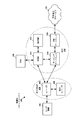
図1Aは、LTEネットワークアーキテクチャ100を示す図である。LTEネットワークアーキテクチャ100は、発展型パケットシステム(EPS)100と呼ばれることがある。EPS100は、1つまたは複数のUE102、発展型UMTS地上波無線アクセスネットワーク(E-UTRAN)104、発展型パケットコア(EPC)110、ホーム加入者サーバ(HSS)120、および事業者のインターネットプロトコル(IP)サービス122を含み得る。EPSは、他のアクセスネットワークと相互接続することができるが、簡単のために、それらのエンティティ/インターフェースは図示されていない。図示のように、EPSはパケット交換サービスを提供するが、当業者が容易に諒解するように、本開示全体にわたって提示される様々な概念は、回線交換サービスを提供するネットワークに拡張され得る。
FIG. 1A is a diagram illustrating an LTE network architecture 100. The LTE network architecture 100 may be referred to as an evolved packet system (EPS) 100. EPS100 consists of one or
E-UTRANは、eNB106および他のeNB108を含む。eNB106は、UE102に対してユーザプレーンプロトコル終端および制御プレーンプロトコル終端を提供する。eNB106は、バックホール(たとえばX2インターフェース)を介して他のeNB108に接続され得る。eNB106は、基地局、ノードB、アクセスポイント、トランシーバ基地局、無線基地局、無線トランシーバ、トランシーバ機能、基本サービスセット(BSS)、拡張サービスセット(ESS)、または他の何らかの適切な用語で呼ばれる場合もある。eNB106は、UE102にEPC110へのアクセスポイントを提供する。UE102の例には、携帯電話、スマートフォン、セッション開始プロトコル(SIP)電話、ラップトップ、携帯情報端末(PDA)、衛星無線、全地球測位システム、マルチメディアデバイス、ビデオデバイス、デジタルオーディオプレーヤ(たとえば、MP3プレーヤ)、カメラ、ゲームコンソール、タブレット、または同様に機能する任意の他のデバイスが含まれる。UE102はまた、当業者により、移動局、加入者局、モバイルユニット、加入者ユニット、ワイヤレスユニット、リモートユニット、モバイルデバイス、ワイヤレスデバイス、ワイヤレス通信デバイス、リモートデバイス、モバイル加入者局、アクセス端末、モバイル端末、ワイヤレス端末、リモート端末、ハンドセット、ユーザエージェント、モバイルクライアント、クライアント、または他の何らかの適切な用語で呼ばれる場合もある。
The E-UTRAN includes an
eNB106はEPC110に接続される。EPC110は、モビリティ管理エンティティ(MME)112、他のMME114、サービングゲートウェイ116、およびパケットデータネットワーク(PDN)ゲートウェイ118を含む。MME112は、UE102とEPC110との間のシグナリングを処理する制御ノードである。一般に、MME112は、ベアラおよび接続の管理を提供する。すべてのユーザIPパケットは、サービングゲートウェイ116を通じて転送され、サービングゲートウェイ116自体は、PDNゲートウェイ118に接続される。PDNゲートウェイ118は、UEのIPアドレス割振りおよび他の機能を実現する。PDNゲートウェイ118は、事業者のIPサービス122に接続される。事業者のIPサービス122は、インターネット、イントラネット、IPマルチメディアサブシステム(IMS)、およびPSストリーミングサービス(PSS)を含み得る。MBMS無線アクセスネットワークにおいて、ブロードキャスト/マルチキャストサービスセンタ(BM-SC)136は、コンテンツプロバイダのためのポータルまたはエントリポイントとして働き得、何らかの認証および他のサービスを提供し得る。ブロードキャスト/マルチキャスト管理エンティティ(BME)124は、制御シグナリングを受信、処理、および/または転送するように構成され得、MBMS制御シグナリングを受信するためのeNB106またはeNB108を選択するために使用され得る。
The
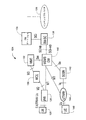
図1Bは、MBSFNサービスを提供またはサポートするための、ワイヤレス通信システム124の機能エンティティを示す。サービス品質(QoS)に関して、システム124は保証ビットレート(GBR)タイプのMBMSベアラを使用し、ここで最大ビットレート(MBR)はGBRに等しい。これらの構成要素は例として示され説明されており、本明細書で説明される進歩性のある概念を限定するものではなく、この概念は、マルチキャスト送信を配信および制御するための他のアーキテクチャおよび機能分散に対して採用され得る。
FIG. 1B shows functional entities of the
システム124は、MBMSゲートウェイ(MBMS GW)140を含み得る。MBMS GW140は、M1インターフェースを介したeノードB128へのMBMSユーザプレーンデータのインターネットプロトコル(IP)マルチキャスト配信を制御し、多くの可能なeNBのうちの1つのeNB128が示されている。加えて、MBMS GWは、M1インターフェースを介したUTRAN無線ネットワークコントローラ(RNC)144へのMBMSユーザプレーンデータのIPマルチキャスト配信を制御し、多くの可能なRNCのうちの1つのUTRAN RNC144が示されている。M1インターフェースは、MBMSデータ(ユーザプレーン)に関連付けられ、データパケットの配信のためにIPを利用する。eNB128は、E-UTRAN Uuインターフェースを介してMBMSコンテンツをユーザ機器(UE)/モバイルエンティティ126に提供し得る。RNC144は、Uuインターフェースを介してMBMSコンテンツをUEモバイルエンティティ146に提供し得る。MBMS GW140はさらに、MBMSセッション制御シグナリング、たとえば、モビリティ管理エンティティ(MME)132およびSmインターフェースを介したMBMSのセッションの開始およびセッションの停止を実行し得る。MBMS GW140はさらに、MBMSベアラを使用するエンティティにSG-mb(ユーザプレーン)の基準点を通じてインターフェースを提供し得、MBMSベアラを使用するエンティティにSGi-mb(制御プレーン)の基準点を通じてインターフェースを提供し得る。SG-mbインターフェースは、MBMSベアラサービス固有のシグナリングを搬送する。SGi-mbインターフェースは、MBMSデータ配信のためのユーザプレーンインターフェースである。MBMSデータ配信は、デフォルトモードであり得るIPユニキャスト送信によって、またはIPマルチキャストによって実行され得る。MBMS GW140は、サービング汎用パケット無線サービスサポートノード(SGSN)142およびSn/Iuインターフェースを介して、UTRAN上でMBMSに対する制御プレーン機能を提供し得る。
システム124はさらに、マルチキャスト協調エンティティ(MCE)130を含み得る。MCE130は、アドミッション制御機能形式のMBMSコンテンツを実行し、MBSFN動作を使用するマルチセルMBMS送信のためにMBSFNエリア中のすべてのeNBによって使用される時間および周波数無線リソースを割り振ることができる。MCE130は、たとえば、変調およびコーディング方式などのMBSFNエリアに対する無線構成を決定し得る。MCE130は、MBMSコンテンツのユーザプレーン送信をスケジューリングおよび制御し得、どのサービスがどのマルチキャストチャネル(MCH)において多重化されるべきかを決定することによって、eMBMSサービスの多重化を管理し得る。MCE130は、M3インターフェースを通じてMME132とのMBMSセッション制御シグナリングに参加し得、制御プレーンインターフェースM2をeNB128に提供し得る。
The
システム124はさらに、コンテンツプロバイダサーバ138と通信するブロードキャストマルチキャストサービスセンタ(BM-SC)136を含み得る。BM-SC136は、コンテンツプロバイダ138などの1つまたは複数のソースからのマルチキャストコンテンツの取り込みを処理し得、以下で説明されるような他の高水準の管理機能を提供し得る。これらの機能は、たとえば、特定されたUEに対するMBMSサービスの認証および開始を含む、メンバーシップ機能を含み得る。BM-SC136はさらに、MBMSセッションおよび送信機能、ライブブロードキャストのスケジューリング、ならびに、MBMSおよび関連する配信機能を含む配信を、実行し得る。BM-SC136はさらに、マルチキャストのために利用可能なコンテンツを告知することなどの、サービスの告知および説明を提供し得る。別個のパケットデータプロトコル(PDP)コンテキストが、UEとBM-SCとの間で制御メッセージを搬送するために使用され得る。BM-SCはさらに、鍵管理などのセキュリティ機能を提供し得、データボリュームおよびQoSなどのパラメータに従ってコンテンツプロバイダの課金を管理し得、ブロードキャストモードに対するUTRANおよびE-UTRANにおけるMBMSのためのコンテンツの同期を実現し得、UTRANにおいてMBSFNデータのヘッダ圧縮を実現し得る。BM-SC136は、QoSおよびMBMSサービスエリアなどのセッション属性を含む、セッションの開始、更新、および停止を、MBMS-GW140に示し得る。
The
システム124はさらに、MCE130およびMBMS-GW140と通信するモビリティ管理エンティティ(MME)132を含み得る。MME132は、E-UTRAN上でMBMSのための制御プレーン機能を提供し得る。加えて、MMEは、MBMS-GW140によって定義されるマルチキャスト関連の情報を、eNB128、144に提供し得る。MME132とMBMS-GW140との間のSmインターフェースは、MBMS制御シグナリング、たとえば、セッション開始信号およびセッション停止信号を搬送するために使用され得る。
The
システム124はさらに、P-GWと省略されることがあるパケットデータネットワーク(PDN)ゲートウェイ(GW)134を含み得る。P-GW134は、シグナリングおよび/またはユーザデータのために、UE126とBM-SC136との間に発展型パケットシステム(EPS)ベアラを提供し得る。したがって、P-GWは、UEに割り当てられたIPアドレスに関連して、UEが起源であるユニフォームリソースロケータ(URL)ベースの要求を受信することができる。BM-SC136はまた、P-GW134を介して1つまたは複数のコンテンツプロバイダにリンクされ得、P-GW134はIPインターフェースを介してBM-SC136と通信し得る。
The
図2は、LTEネットワークアーキテクチャにおけるアクセスネットワーク200の一例を示す図である。この例では、アクセスネットワーク200は、いくつかのセルラー領域(セル)202に分割されている。1つまたは複数の低電力クラスeNB208は、セル202のうちの1つまたは複数と重複するセルラー領域210を有し得る。低電力クラスeNB208は、フェムトセル(たとえば、ホームeNB(HeNB))、ピコセル、マイクロセル、またはリモート無線ヘッド(RRH)であり得る。マクロeNB204は各々、それぞれのセル202に割り当てられ、セル202中のすべてのUE206にEPC110へのアクセスポイントを提供するように構成される。アクセスネットワーク200のこの例では集中型コントローラはないが、代替構成では集中型コントローラが使用されてよい。eNB204は、無線ベアラ制御、アドミッション制御、モビリティ制御、スケジューリング、セキュリティ、およびサービングゲートウェイ116への接続性を含む、すべての無線関連機能を担当する。
FIG. 2 is a diagram illustrating an example of an
アクセスネットワーク200によって利用される変調方式および多元接続方式は、導入されている特定の電気通信規格に応じて異なる場合がある。LTEの適用例では、DL上ではOFDMが使用され、UL上ではSC-FDMAが使用されて、周波数分割複信(FDD)と時分割複信(TDD)の両方をサポートする。当業者が以下の詳細な説明から容易に諒解するように、本明細書に提示される様々な概念は、LTEの適用例に好適である。しかしながら、これらの概念は、他の変調技法および多元接続技法を採用する他の電気通信規格に容易に拡張され得る。例として、これらの概念は、エボリューションデータオプティマイズド(EV-DO)またはウルトラモバイルブロードバンド(UMB)に拡張され得る。EV-DOおよびUMBは、CDMA2000規格ファミリの一部として第3世代パートナーシッププロジェクト2(3GPP2)によって公表されたエアインターフェース規格であり、CDMAを利用してブロードバンドインターネットアクセスを移動局に提供する。これらの概念はまた、広帯域CDMA(W-CDMA)およびTD-SCDMAなどのCDMAの他の変形形態を利用するユニバーサル地上波無線アクセス(UTRA)、TDMAを利用するモバイル通信用グローバルシステム(GSM(登録商標))、ならびにOFDMAを利用する発展型UTRA(E-UTRA)、IEEE802.11(Wi-Fi)、IEEE802.16(WiMAX)、IEEE802.20、およびフラッシュOFDMに拡張され得る。UTRA、E-UTRA、UMTS、LTE、およびGSM(登録商標)は、3GPP団体からの文書に記載されている。CDMA2000およびUMBは、3GPP2団体からの文書に記載されている。採用される実際のワイヤレス通信規格および多元接続技術は、特定の適用例およびシステムに課された全体的な設計制約に依存する。
The modulation scheme and multiple access scheme utilized by
eNB204は、MIMO技術をサポートする複数のアンテナを有し得る。MIMO技術の使用により、eNB204が空間領域を活用して、空間多重化、ビームフォーミング、および送信ダイバーシティをサポートすることが可能になる。空間多重化は、同じ周波数で同時にデータの様々なストリームを送信するために使用され得る。データストリームは、データレートを増大させるために単一のUE206に送信されてよく、または全体的なシステム容量を増大させるために複数のUE206に送信されてもよい。これは、各データストリームを空間的にプリコーディングし(すなわち、振幅および位相のスケーリングを適用し)、次いで、空間的にプリコーディングされた各ストリームをDL上で複数の送信アンテナを通じて送信することによって実現される。空間的にプリコーディングされたデータストリームは、異なる空間シグネチャとともにUE206に到達し、これにより、UE206の各々は、そのUE206に向けられた1つまたは複数のデータストリームを復元することが可能になる。UL上では、各UE206は、空間的にプリコーディングされたデータストリームを送信し、これにより、eNB204は、空間的にプリコーディングされた各データストリームのソースを特定することが可能になる。
The
空間多重化は、一般に、チャネル状態が良好なときに使用される。チャネル状態がさほど好ましくないときは、送信エネルギーを1つまたは複数の方向に集中させるために、ビームフォーミングが使用され得る。これは、複数のアンテナを通じた送信のためにデータを空間的にプリコーディングすることによって実現され得る。セルの縁部において良好なカバレージを実現するために、単一ストリームのビームフォーミング送信が、送信ダイバーシティと組み合わせて使用され得る。 Spatial multiplexing is generally used when channel conditions are good. When channel conditions are less favorable, beamforming can be used to concentrate the transmit energy in one or more directions. This can be achieved by spatially precoding the data for transmission through multiple antennas. A single stream beamforming transmission may be used in combination with transmit diversity to achieve good coverage at the edge of the cell.
以下の詳細な説明では、アクセスネットワークの様々な態様が、DL上でOFDMをサポートするMIMOシステムを参照して説明される。OFDMは、OFDMAシンボル内のいくつかのサブキャリアにわたってデータを変調するスペクトル拡散技法である。サブキャリアは、正確な周波数で離間される。離間は、受信機がサブキャリアからのデータを復元することを可能にする「直交性」をもたらす。時間領域では、OFDMシンボル間干渉をなくすために、CPなどのガードインターバルが各OFDMAシンボルに追加され得る。ULは、SC-FDMAをDFT拡散OFDM信号の形式で使用して、高いピーク対平均電力比(PAPR)を補償することができる。 In the detailed description that follows, various aspects of an access network will be described with reference to a MIMO system supporting OFDM on the DL. OFDM is a spread spectrum technique that modulates data across several subcarriers within an OFDMA symbol. The subcarriers are spaced at a precise frequency. The separation provides “orthogonality” that allows the receiver to recover the data from the subcarriers. In the time domain, a guard interval such as CP may be added to each OFDMA symbol to eliminate OFDM intersymbol interference. UL can use SC-FDMA in the form of DFT spread OFDM signals to compensate for high peak-to-average power ratio (PAPR).
図3は、LTEにおけるDLフレーム構造の一例を示す図300である。フレーム(10ミリ秒)は、等しいサイズの10個のサブフレームに分割され得る。各サブフレームは、連続する2つの時間スロットを含み得る。リソースグリッドは、2つの時間スロットを表すために使用され得、各時間スロットはリソースブロックを含む。リソースグリッドは、複数のリソース要素に分割される。LTEでは、リソースブロックは、周波数領域の中で連続する12個のサブキャリアを含み、各OFDMAシンボルの中のノーマルCPの場合、時間領域の中で連続する7個のOFDMAシンボル、すなわち84個のリソース要素を含む。拡張CPの場合、リソースブロックは、時間領域の中で連続する6つのOFDMAシンボルを含み、72個のリソース要素を有する。R302、R304として示されたリソース要素のうちのいくつかは、DL基準信号(DL-RS)を含む。DL-RSは、(共通RSと呼ばれることもある)セル固有RS(CRS)302、およびUE固有RS(UE-RS)304を含む。UE-RS304は、対応する物理DL共有チャネル(PDSCH)がマッピングされるリソースブロック上のみで送信される。各リソース要素によって搬送されるビット数は、変調方式に依存する。したがって、UEが受信するリソースブロックが多いほど、かつ変調方式が高いほど、UE向けのデータレートは高くなる。
FIG. 3 is a diagram 300 illustrating an example of a DL frame structure in LTE. A frame (10 milliseconds) may be divided into 10 equally sized subframes. Each subframe may include two consecutive time slots. A resource grid may be used to represent two time slots, where each time slot includes a resource block. The resource grid is divided into a plurality of resource elements. In LTE, a resource block includes 12 subcarriers that are continuous in the frequency domain, and in the case of normal CP in each OFDMA symbol, 7 OFDMA symbols that are continuous in the time domain, that is, 84 OFDM symbols. Contains resource elements. In the case of the extended CP, the resource block includes six OFDMA symbols that are continuous in the time domain and has 72 resource elements. Some of the resource elements indicated as R302, R304 include a DL reference signal (DL-RS). The DL-RS includes a cell-specific RS (CRS) 302 (sometimes referred to as a common RS) and a UE-specific RS (UE-RS) 304. UE-
図4は、LTEにおけるULフレーム構造の一例を示す図400である。ULのために利用可能なリソースブロックは、データセクションおよび制御セクションに区分化され得る。制御セクションは、システム帯域幅の2つの縁部に形成され得、構成可能なサイズを有し得る。制御セクション内のリソースブロックは、制御情報の送信のためにUEに割り当てられ得る。データセクションは、制御セクションに含まれないすべてのリソースブロックを含み得る。ULフレーム構造により、データセクションは連続的なサブキャリアを含むことになり、これにより、単一のUEが、データセクション内の連続するサブキャリアのすべてを割り当てられることが可能になり得る。 FIG. 4 is a diagram 400 illustrating an example of a UL frame structure in LTE. The resource blocks available for UL can be partitioned into a data section and a control section. The control section can be formed at two edges of the system bandwidth and can have a configurable size. Resource blocks in the control section may be allocated to the UE for transmission of control information. The data section may include all resource blocks that are not included in the control section. Due to the UL frame structure, the data section will include consecutive subcarriers, which may allow a single UE to be assigned all of the consecutive subcarriers in the data section.
UEは、制御情報をeNBに送信するために、制御セクション内のリソースブロック410a、410bを割り当てられ得る。UEはまた、データをeNBに送信するために、データセクション内のリソースブロック420a、420bを割り当てられ得る。UEは、制御セクションの中で割り当てられたリソースブロック上の物理UL制御チャネル(PUCCH)内で、制御情報を送信し得る。UEは、データセクションの中で割り当てられたリソースブロック上の物理UL共有チャネル(PUSCH)内で、データのみ、またはデータと制御情報の両方を送信し得る。UL送信は、サブフレームの両方のスロットにまたがることができ、周波数にわたってホップすることができる。
The UE may be assigned
初期システムアクセスを実行し、物理ランダムアクセスチャネル(PRACH)430内でUL同期を実現するために、1組のリソースブロックを使用することができる。PRACH430は、ランダムシーケンスを搬送し、いかなるULデータ/シグナリングも搬送することができない。各ランダムアクセスプリアンブルは、連続する6つのリソースブロックに対応する帯域幅を占有する。開始周波数は、ネットワークによって指定される。すなわち、ランダムアクセスプリアンブルの送信は、特定の時間リソースおよび周波数リソースに制限される。PRACHの場合、周波数ホッピングは存在しない。PRACHの試行は、単一のサブフレーム(1ミリ秒)内で、または少数の連続するサブフレームのシーケンス内で搬送され、UEは、フレーム(10ミリ秒)ごとに単一のPRACHの試行しか行うことができない。 A set of resource blocks can be used to perform initial system access and achieve UL synchronization within the physical random access channel (PRACH) 430. PRACH430 carries random sequences and cannot carry any UL data / signaling. Each random access preamble occupies a bandwidth corresponding to six consecutive resource blocks. The starting frequency is specified by the network. That is, transmission of the random access preamble is limited to specific time resources and frequency resources. For PRACH, there is no frequency hopping. PRACH attempts are carried in a single subframe (1 ms) or in a sequence of a few consecutive subframes, and the UE can only have a single PRACH attempt every frame (10 ms). I can't do it.
図5は、LTEにおけるユーザプレーンおよび制御プレーンのための無線プロトコルアーキテクチャの一例を示す図500である。UEおよびeNBのための無線プロトコルアーキテクチャは、レイヤ1、レイヤ2、およびレイヤ3という3つのレイヤで示される。レイヤ1(L1レイヤ)は、最下位レイヤであり、様々な物理レイヤ信号処理機能を実装する。本明細書では、L1レイヤは物理レイヤ506と呼ばれる。レイヤ2(L2レイヤ)508は、物理レイヤ506の上にあり、物理レイヤ506を介したUEとeNBとの間のリンクを担当する。
FIG. 5 is a diagram 500 illustrating an example of a radio protocol architecture for a user plane and a control plane in LTE. The radio protocol architecture for the UE and eNB is shown in three layers:
ユーザプレーンでは、L2レイヤ508は、媒体アクセス制御(MAC)サブレイヤ510、無線リンク制御(RLC)サブレイヤ512、およびパケットデータコンバージェンスプロトコル(PDCP)514サブレイヤを含み、これらはネットワーク側のeNBで終端される。図示されていないが、UEは、L2レイヤ508の上にいくつかの上位レイヤを有する場合があり、これらは、ネットワーク側のPDNゲートウェイ118で終端されるネットワークレイヤ(たとえば、IPレイヤ)と、接続の他端(たとえば、遠端UE、サーバなど)で終端されるアプリケーションレイヤとを含む。
In the user plane, the
PDCPサブレイヤ514は、様々な無線ベアラと論理チャネルとの間の多重化を実現する。PDCPサブレイヤ514はまた、無線送信のオーバーヘッドを低減するための上位レイヤのデータパケット用のヘッダ圧縮、データパケットを暗号化することによるセキュリティ、およびeNB間のUE用のハンドオーバのサポートを実現する。RLCサブレイヤ512は、上位レイヤのデータパケットのセグメント化および再アセンブリ、紛失したデータパケットの再送信、ならびに、ハイブリッド自動再送要求(HARQ)に起因して順序が乱れた受信を補償するデータパケットの並べ替えを実現する。MACサブレイヤ510は、論理チャネルとトランスポートチャネルとの間の多重化を実現する。MACサブレイヤ510はまた、1つのセルの中の様々な無線リソース(たとえば、リソースブロック)をUEの間で割り振ることを担当する。MACサブレイヤ510はまた、HARQ動作を担当する。
The
制御プレーンでは、UEおよびeNBのための無線プロトコルアーキテクチャは、制御プレーン用のヘッダ圧縮機能がないことを除き、物理レイヤ506およびL2レイヤ508について実質的に同じである。制御プレーンはまた、レイヤ3(L3レイヤ)内に無線リソース制御(RRC)サブレイヤ516を含む。RRCサブレイヤ516は、無線リソース(すなわち、無線ベアラ)を取得すること、およびeNBとUEとの間のRRCシグナリングを使用して下位レイヤを構成することを担当する。
In the control plane, the radio protocol architecture for the UE and eNB is substantially the same for the
図6は、アクセスネットワーク中でUE650と通信するeNB610のブロック図である。DLでは、コアネットワークからの上位レイヤパケットが、コントローラ/プロセッサ675に供給される。コントローラ/プロセッサ675は、L2レイヤの機能を実装する。DLでは、コントローラ/プロセッサ675は、ヘッダ圧縮、暗号化、パケットのセグメント化および並べ替え、論理チャネルとトランスポートチャネルとの間の多重化、ならびに、様々な優先順位基準に基づくUE650への無線リソース割振りを実現する。コントローラ/プロセッサ675はまた、HARQ動作、紛失したパケットの再送信、およびUE650へのシグナリングを担当する。
FIG. 6 is a block diagram of
送信(TX)プロセッサ616は、L1レイヤ(すなわち、物理レイヤ)のための様々な信号処理機能を実装する。信号処理機能は、UE650での順方向誤り訂正(FEC)を容易にするコーディングおよびインターリービング、ならびに様々な変調方式(たとえば、2位相シフトキーイング(BPSK)、直交位相シフトキーイング(QPSK)、M位相シフトキーイング(M-PSK)、M直交振幅変調(M-QAM))に基づく信号コンスタレーションへのマッピングを含む。次いで、コーディングおよび変調されたシンボルは、並列ストリームに分割される。次いで、各ストリームは、OFDMサブキャリアにマッピングされ、時間領域および/または周波数領域において基準信号(たとえば、パイロット)と多重化され、次いで、逆高速フーリエ変換(IFFT)を使用して一緒に結合されて、時間領域のOFDMAシンボルストリームを搬送する物理チャネルを生成する。OFDMストリームは、空間的にプリコーディングされて、複数の空間ストリームを生成する。チャネル推定器674からのチャネル推定値は、コーディングおよび変調方式を決定するために、ならびに空間処理のために使用され得る。チャネル推定値は、UE650によって送信された基準信号および/またはチャネル状態フィードバックから導出され得る。次いで、各空間ストリームは、別個の送信機618TXを介して異なるアンテナ620に供給され得る。各送信機618TXは、送信用のそれぞれの空間ストリームでRFキャリアを変調し得る。
The transmit (TX) processor 616 implements various signal processing functions for the L1 layer (ie, physical layer). Signal processing functions include coding and interleaving to facilitate forward error correction (FEC) at the UE650, as well as various modulation schemes (e.g., binary phase shift keying (BPSK), quadrature phase shift keying (QPSK), M phase Includes mapping to signal constellation based on shift keying (M-PSK), M quadrature amplitude modulation (M-QAM). The coded and modulated symbols are then divided into parallel streams. Each stream is then mapped to an OFDM subcarrier, multiplexed with a reference signal (e.g., pilot) in the time domain and / or frequency domain, and then combined together using an inverse fast Fourier transform (IFFT). A physical channel carrying the time-domain OFDMA symbol stream. The OFDM stream is spatially precoded to generate multiple spatial streams. The channel estimate from
UE650において、各受信機654RXは、それぞれのアンテナ652を介して信号を受信する。各受信機654RXは、RFキャリア上に変調された情報を復元し、その情報を受信(RX)プロセッサ656に供給する。RXプロセッサ656は、L1レイヤの様々な信号処理機能を実施する。RXプロセッサ656は、情報に対して空間処理を実行して、UE650に宛てられた任意の空間ストリームを復元し得る。複数の空間ストリームがUE650に向けられている場合、これらをRXプロセッサ656によって単一のOFDMAシンボルストリームに結合することができる。次いで、RXプロセッサ656は、高速フーリエ変換(FFT)を使用して、OFDMAシンボルストリームを時間領域から周波数領域に変換する。周波数領域信号は、OFDM信号の各サブキャリアに関して別個のOFDMAシンボルストリームを含む。各サブキャリア上のシンボル、および基準信号は、eNB610によって送信された最も可能性の高い信号コンスタレーションポイントを決定することによって、復元および復調される。これらの軟判定は、チャネル推定器658によって計算されたチャネル推定値に基づき得る。次いで、軟判定は復号およびデインターリーブされて、物理チャネル上でeNB610によって元々送信されたデータおよび制御信号を復元する。次いで、データおよび制御信号は、コントローラ/プロセッサ659に供給される。
In
コントローラ/プロセッサ659は、L2レイヤを実装する。コントローラ/プロセッサは、プログラムコードおよびデータを記憶するメモリ660と関連付けることができる。メモリ660は、コンピュータ可読媒体と呼ばれることがある。ULでは、コントローラ/プロセッサ659は、トランスポートチャネルと論理チャネルとの間の逆多重化、パケット再アセンブリ、暗号化解除、ヘッダ圧縮解除、制御信号処理を実現して、コアネットワークからの上位レイヤパケットを復元する。次いで、上位レイヤパケットはデータシンク662に供給され、データシンク662はL2レイヤの上のすべてのプロトコルレイヤを表す。様々な制御信号も、L3処理のためにデータシンク662に供給され得る。コントローラ/プロセッサ659はまた、HARQ動作をサポートするために、確認応答(ACK)および/または否定応答(NACK)のプロトコルを使用する誤り検出を担当する。
The controller /
ULでは、コントローラ/プロセッサ659に上位レイヤパケットを供給するために、データソース667が使用される。データソース667は、L2レイヤの上のすべてのプロトコルレイヤを代表する。eNB610によるDL送信に関連して説明された機能と同様に、コントローラ/プロセッサ659は、ヘッダ圧縮、暗号化、パケットのセグメント化および並べ替え、ならびに、eNB610による無線リソース割振りに基づく論理チャネルとトランスポートチャネルとの間の多重化を実現することによって、ユーザプレーンおよび制御プレーンのためのL2レイヤを実装する。コントローラ/プロセッサ659はまた、HARQ動作、紛失したパケットの再送信、およびeNB610へのシグナリングを担当する。
In UL, a
eNB610によって送信された基準信号またはフィードバックからチャネル推定器658によって導出されたチャネル推定値は、適切なコーディングおよび変調方式を選択し、空間処理を容易にするために、TXプロセッサ668によって使用され得る。TXプロセッサ668によって生成された空間ストリームは、別個の送信機654TXを介して異なるアンテナ652に供給され得る。各送信機654TXは、送信用のそれぞれの空間ストリームを用いてRFキャリアを変調し得る。
The channel estimate derived by the
UL送信は、UE650での受信機機能に関連して説明された方式と同様の方式で、eNB610で処理される。各受信機618RXは、それぞれのアンテナ620を通じて信号を受信する。各受信機618RXは、RFキャリア上に変調された情報を復元し、その情報をRXプロセッサ670に供給する。RXプロセッサ670は、L1層を実装し得る。
UL transmission is processed at
コントローラ/プロセッサ675は、L2レイヤを実装する。コントローラ/プロセッサ675は、プログラムコードおよびデータを記憶するメモリ676と関連付けることができる。メモリ676は、コンピュータ可読媒体と呼ばれることがある。ULでは、コントローラ/プロセッサ675は、トランスポートチャネルと論理チャネルとの間の逆多重化、パケット再アセンブリ、暗号化解除、ヘッダ圧縮解除、制御信号処理を実現して、UE650からの上位レイヤパケットを復元する。コントローラ/プロセッサ675からの上位レイヤパケットは、コアネットワークに供給され得る。コントローラ/プロセッサ675はまた、HARQ動作をサポートするために、ACKおよび/またはNACKのプロトコルを使用する誤り検出を担当する。
The controller /
図7は、MBSFN内の発展型マルチキャストブロードキャストマルチメディアサービス(eMBMS)を示す図750である。セル752'内のeNB752は第1のMBSFNエリアを形成し得、セル754'内のeNB754は第2のMBSFNエリアを形成し得る。eNB752、754は、他のMBSFNエリア、たとえば、合計8つまでのMBSFNエリアと関連付けられ得る。MBSFNエリア内のセルは、予約セルに指定され得る。予約セルは、マルチキャスト/ブロードキャストのコンテンツを供給しないが、セル752'、754'に時間同期され、MBSFNエリアへの干渉を制限するために、MBSFNリソース上で規制された電力を有する。MBSFNエリア内の各eNBは、同期方式で、同じeMBMSの制御情報およびデータを同期して送信する。各エリアは、ブロードキャストサービス、マルチキャストサービス、およびユニキャストサービスをサポートし得る。ユニキャストサービスは、特定のユーザを対象とするサービス、たとえば、音声通話である。マルチキャストサービスは、あるグループのユーザによって受信され得るサービス、たとえば、サブスクリプションビデオサービスである。ブロードキャストサービスは、すべてのユーザによって受信され得るサービス、たとえば、ニュース放送である。図7を参照すると、第1のMBSFNエリアは、特定のニュース放送をUE770に供給することなどによって、第1のeMBMSブロードキャストサービスをサポートし得る。第2のMBSFNエリアは、異なるニュース放送をUE760に供給することなどによって、第2のeMBMSブロードキャストサービスをサポートし得る。各MBSFNエリアは、複数の物理マルチキャストチャネル(PMCH)(たとえば、15個のPMCH)をサポートする。各PMCHは、マルチキャストチャネル(MCH)に対応する。各MCHは、複数(たとえば、29個)のマルチキャスト論理チャネルを多重化することができる。各MBSFNエリアは、1つのマルチキャスト制御チャネル(MCCH)を有し得る。したがって、1つのMCHは、1つのMCCHおよび複数のマルチキャストトラフィックチャネル(MTCH)を多重化することができ、残りのMCHは、複数のMTCHを多重化することができる。
FIG. 7 is a diagram 750 illustrating an evolved multicast broadcast multimedia service (eMBMS) in MBSFN. The
OFDMシンボル間干渉を抑制しサブキャリア間の直交性を維持するためのガードインターバルを設けるために、OFDMシンボルの始まりにCPが追加される。たとえば、eNBとUEとの間のチャネル内に複数の通信経路が存在することによって引き起こされる時間分散性チャネルの問題が原因で、符号間干渉が発生し得る。図8は、符号間干渉を生じ得る例示的なシナリオ800およびシナリオ840を示す図である。図8はまた、UE804において観測されるような伝搬遅延の影響を示すタイミングチャート820を含む。例示的なシナリオ800は、UE804と通信する単一のeNB802に関する。UE804においてeNB802から受信されるシンボル822は、直接伝搬経路808によって進行し、シンボル822の遅延したバージョンは、たとえば、建物であるかもしれない物体806における反射によって作り出された長い間接伝搬経路810からの遅延シンボル828として到達する。シンボル822の到達時間832と遅延シンボル828の到達時間834との差がCP継続時間よりも短い場合、符号間干渉は発生せず、シンボル822およびシンボル828は、UE804において合成され得る。示される例では、CP824の継続時間は、時間830において終わる遅延シンボル828と次のシンボル826との間の符号間干渉を防ぐために十分長い。シンボル822のUE804における直接経路808を通じた到達時間832と遅延シンボル828のUE804における到達時間834との差は、シナリオ800の遅延スプレッドと呼ばれることがあり、詳細には、間接経路810は、eNB802とUE804との間で利用可能な最長の間接伝搬経路である。間接経路は、eNB802およびUE804と関連した最長の伝搬経路長および/または遅延を有し得る。
CP is added to the beginning of the OFDM symbol in order to provide a guard interval for suppressing inter-OFDM symbol interference and maintaining orthogonality between subcarriers. For example, intersymbol interference can occur due to the problem of time dispersive channels caused by the presence of multiple communication paths in the channel between the eNB and the UE. FIG. 8 is a diagram illustrating an
タイミングチャート820はまた、eNB842およびeNB846が、UE844から著しく異なる距離に位置し得、または長さが著しく異なる1つまたは複数の伝搬経路に沿って送信し得る、eMBMSシナリオ840の代表であり得る。その結果、それぞれeNB842およびeNB846によって同期的な方式で送信されるシンボル822および遅延シンボル828は、UE844において異なる時間に到達し得る。タイミングチャート820に示すように、UE844において受信される次のシンボル826のCP824の継続時間中に遅延シンボル828の終わりが発生する場合、符号間干渉は避けられ得る。シンボル822と828との間の遅延スプレッドがCP継続時間よりも短い場合、異なる伝搬経路によって到達するシンボル822およびシンボル828は、UE804において合成され得る。シンボル822のUE844における最短の伝搬経路(ここでは、近くのeNB842)による到達時間832と、シンボル828のUE844における遠くのeNB846からの到達時間834との間の差は、eMBMSシナリオ840の遅延スプレッドと呼ばれることがある。eMBMSシナリオ840に関する遅延スプレッドは、通常、最も近くのeNB842からの直接経路808に対応し得るeNB842またはeNB846とUE844との間の最短の伝搬経路長と関連した到達時間832と、通常は最も遠くのeNB846からの、MBSFNエリアにおける最長の間接経路810に対応し得るeNB842またはeNB846とUE844との間の最長の伝搬経路長と関連した到達時間834とを使用して計算され得る。最長の伝搬経路長はまた、より長い間接伝搬経路が近くのeNB842とUE844との間に存在するとき、遠くのeNB846よりも近いeNB846と関連し得る。
具体的には、MBSFNエリアがそれに対応して大きい遅延スプレッドを発生させる大きいセルを備えるとき、LTEは、eMBMSのためにノーマルCPの代わりに使用され得る拡張CPを規定する。たとえば、拡張CPの継続時間はLTEに関して16.7μ秒であってよく、ノーマルCPの継続時間は4.7μ秒または5.1μ秒であってよい。eMBMSでは、CP824は、MBSFNの中で異なるeNB842、846から受信される送信のタイミング差をカバーすることを必要とされ得る。MBSFNにおけるUE844は、10〜40ワットの範囲の送信電力を有する近くのeNB842から、およびより大きい送信電力、たとえば、80kW以上を有し、UE842までの比較的長い(たとえば、20キロメートル(km)まで、およびそれを越える長さ)伝搬経路長を有する遠くのeNB846から、信号を受信し得る。長いCP継続時間は、eNB842と846の両方からの信号が合成されることを可能にし、UE844と送信電力が大きい遠くのeNB846との間のより長い伝搬経路に関する符号間干渉を回避するために使用され得る。いくつかの実施形態では、拡張CPの継続時間よりも少なくとも2倍または3倍長いCP継続時間が使用され得る。シンボルおよびCPを送信するために必要となる時間のパーセンテージとしてのCP継続時間は、CPオーバーヘッドと呼ばれることがある。いくつかの実施形態は、増大したCPオーバーヘッドを含み得る増大したCP継続時間の影響を補償するために、シンボル継続時間を増大させ得る。
Specifically, LTE defines an extended CP that can be used instead of a normal CP for eMBMS when the MBSFN area comprises a large cell that correspondingly generates a large delay spread. For example, the extended CP duration may be 16.7 μsec for LTE, and the normal CP duration may be 4.7 μsec or 5.1 μsec. In eMBMS,
eMBMSにおいて、各eNBとUEとの間に複数の伝搬経路が存在し得、MBSFNの中の異なるeNBは、互いに異なりUEからのそれらのそれぞれの距離に起因する伝搬遅延を有し得る。図9Aおよび図9Bは、MBSFNエリアにおける遅延スプレッドをより詳細に示す。図9Aおよび図9Bは、3つのeNBが同期方式で時間t0において同じ信号情報をUEに送信する例示的なMBSFNエリアに関する。タイミングチャート900に示すように、複数の信号は、UEによってeNBの各々から受信される。信号の第1のグループ902は、グループ902の中の最初の信号が時間t1において到達してUEにおいて第1のeNBから受信され、信号の第2のグループ904は、グループ904の中の最初の信号が時間t2において到達してUEにおいて第2のeNBから受信され、信号の第3のグループ906は、グループ906の中の最初の信号が時間t3において到達して第3のeNBから受信される。各グループ902、904、および906の中の信号は、異なる時間においてUEに到達し得、t0と各グループ902、904および906の最初の信号の到達、t1、t2、およびt3との間で経過した時間は、それぞれ、グループ902、904および906に関する最小伝搬遅延を表し得る。最小伝搬遅延は、eNBとUEとの間の最短の伝搬経路に対応し得る。
In eMBMS, there may be multiple propagation paths between each eNB and the UE, and different eNBs in the MBSFN may have different propagation delays due to their respective distances from the UE. 9A and 9B show the delay spread in the MBSFN area in more detail. FIGS. 9A and 9B relate to an exemplary MBSFN area in which three eNBs transmit the same signal information to the UE at time t 0 in a synchronous manner. As shown in the
タイミングチャート900はさらに、各eNBとUEとの間の伝搬経路の長さの差が原因で、各eNBによって送信された信号が異なる時間においてUEに到達し得ることを示す。信号グループ902に関して図示するように、信号の遅延したバージョンは、時間t1+x、t1+y、およびt1+zにおいて到達し得る。t1とt1+zとの間で経過した時間は、第1のeNBと関連し第1のeNBとUEとの間の異なる伝搬経路に対応する遅延スプレッドを表し得る。eNBとUEとの間の各伝搬経路は、eNBとUEとの間の他の伝搬経路と同じまたは異なる減衰を有し得る。
図示のように、グループ902の最初の信号は、UEによって受信される最初の信号である(t1)。UEは、1つまたは複数のeNBから受信された1つまたは複数の信号を、統合または合成し得る。時間t1に対してCP1の継続時間の長さよりも短く遅延した信号は、UEにおいて合成され得る。CP1は、図9AのMBSFNについて規定されているCPである。CP1の継続時間よりも長く遅延した信号は、符号間干渉を引き起こし得る。グループ906の中の信号は、チャネルノイズレベルに近いレベルまで減衰されたものとして示され、これらの減衰された信号は、著しい符号間干渉を引き起こすことがなく、またはUEによって見られるようなMSFN利得に著しく寄与することがない。したがって、CP1は、グループ902と906との間の相対的な伝搬遅延(すなわち、t3-t1)よりも短い継続時間を有し得、したがって、グループ906の信号は、第1のeNBおよび第2のeNBからUEにおいて受信された信号とコヒーレントに合成され得ない。
As shown, the first signal of
通常、減衰は伝搬経路長とともに増大する。図9Aに示すように、第3のeNBから受信されたグループ906の信号は、示されているMBSFNにおける最長の伝搬遅延を有し、最も減衰されてもいる。CPの長さは、UEにおいて受信された信号の相対的な伝搬遅延よりも短くなるように構成され得、その場合、相対的な伝搬遅延は、信号の減衰が著しい符号間干渉を引き起こし、またはUEによって見られるMSFNチャネル利得に著しく寄与すると予期されない伝搬経路長に対応する。たとえば、グループ906の信号は、著しく減衰されており、CP1が使用されるときのUEにおけるコヒーレントな組合せから除外され得る。
Usually, the attenuation increases with the propagation path length. As shown in FIG. 9A, the
図9Bは、第3のeNB(グループ906')から受信された信号の電力レベルが、第1のeNBおよび第2のeNBから受信されたグループ902およびグループ904の中の少なくともいくつかの信号の電力レベルと同等である、第1、第2、および第3のeNBに関する遅延スプレッドおよび減衰を示す。受信された信号電力におけるこの類似は、第1のeNBおよび第2のeNBの電力出力に比べて増大されている第3のeNBからの送信機の電力出力の結果であり得る。CPの長さがグループ906'の中の重要な信号の伝搬遅延をカバーするには十分に長くないとき、グループ906'の中の信号の増大されている電力は、著しい符号間干渉を引き起こし得る。したがって、より長いCP継続時間は、MBSFN(CP2)が第3のeNBから受信されたグループ906'の中の信号の伝搬遅延をカバーするように構成され得、それによって、グループ906'の信号が第1のeNBおよび第2のeNBから受信された信号とコヒーレントに合成されてUEにおけるMBSFN利得をもたらすことを可能にする。
FIG. 9B shows that the power level of the signals received from the third eNB (
新型テレビジョンシステム委員会(ATSC)などの様々な地上放送システムにおける特有のブロードキャストのユースケースは、LTEブロードキャスト/eMBMSの派生的な形成にとって役立つことがある。特有の条件に応じて、これらのユースケースは、通常のサイクリックプレフィックスおよび拡張サイクリックプレフィックスなどの既存のLTE規格において名目上は利用可能なものよりも、長いサイクリックプレフィックスから恩恵を受け得る。 Specific broadcast use cases in various terrestrial broadcast systems, such as the Advanced Television System Committee (ATSC), may be useful for the derivative formation of LTE broadcast / eMBMS. Depending on the specific conditions, these use cases can benefit from longer cyclic prefixes than are nominally available in existing LTE standards such as normal cyclic prefixes and extended cyclic prefixes.
考察する第1のユースケースは、低電力、低いタワー高、モバイル、単一周波数ネットワーク(SFN)のネットワークを備える。このユースケースは、屋内、屋外、または車両用にかかわらず、タブレットおよびスマートフォンをサポートし得る典型的なLTEブロードキャスト用途を規定する。低電力は、通常、5MHz当たり2kWの実効等方放射電力(EIRP)の範囲の送信機サイトを有するネットワークを指す。低いタワーは、通常、30mの範囲の放射高を指し、モバイルは、通常、受信アンテナが静止していないサービスのすべてのクラスをサポートするネットワークタイプを指す。ドップラー速度の適用可能な範囲は、ATSCにとって概ね3km/hr〜200km/hrである。現在規定されている16.66μ秒および33.33μ秒のサイクリックプレフィックスは、混合キャリアモードと専用のキャリアモードの両方において十分なはずである。サイクリックプレフィックスのこの選択は、任意のスタンドアロンモードで再現され得る。この配置スタイルはまた、名目上は固定した受信機による屋内の受信にとって適当であり得る。高いドップラーレートは、一般に、このユースケースにとって必要とされず、低速度のドップラーが有益であり得る。そのような受信にとって適切なチャネルモデルは、マルチパスレイリーフェージングモデルである。屋内の受信は、時間的な意味において至近距離からの反射によって支配される可能性が高い。このユースケースが、レイリーフェージングに支配されたチャネルモデルによって支配されているとすれば、MIMOの使用に起因して起こり得る著しい効率の向上があり得る。ここでのMIMOの潜在的な利点は、ネットワークの配置スタイルに依存する。 The first use case to consider comprises a low power, low tower height, mobile, single frequency network (SFN) network. This use case defines a typical LTE broadcast application that can support tablets and smartphones, whether indoors, outdoors, or for vehicles. Low power typically refers to a network having transmitter sites in the range of 2 kW effective isotropic radiated power (EIRP) per 5 MHz. A low tower typically refers to a radiation height in the range of 30 meters, and a mobile typically refers to a network type that supports all classes of service where the receive antenna is not stationary. The applicable range of Doppler speed is approximately 3 km / hr to 200 km / hr for ATSC. The currently specified 16.66 μs and 33.33 μs cyclic prefixes should be sufficient for both mixed and dedicated carrier modes. This selection of cyclic prefix can be reproduced in any standalone mode. This placement style may also be suitable for indoor reception by a nominally fixed receiver. High Doppler rates are generally not needed for this use case, and low speed Dopplers may be beneficial. A suitable channel model for such reception is the multipath Rayleigh fading model. Indoor reception is likely to be dominated by reflections from close range in a temporal sense. If this use case is dominated by a channel model dominated by Rayleigh fading, there can be a significant efficiency increase that can occur due to the use of MIMO. The potential benefits of MIMO here depend on the network deployment style.
この配置スタイルは、単一周波数ネットワーク(SFN)である。通常、そのような配置での周波数再使用は100%であり、配置の秒当たりのビット(bps)/Hzは2bps/Hz以下であるが、変調コーディング方式(MCS)の選択は、マルチキャストブロードキャストマルチメディアサービスSFN(MBSFN)エリア内のサイト密度およびサイトの総数によって最終的に決定され得る。あるMBSFNから別のものへの移行に関して干渉領域が存在し、このことはネットワーク設計において考慮されなければならない。 This deployment style is a single frequency network (SFN). Typically, frequency reuse in such an arrangement is 100%, and the bits per second (bps) / Hz of the arrangement is 2 bps / Hz or less, but the modulation coding scheme (MCS) choice is It can ultimately be determined by the site density and the total number of sites in the Media Service SFN (MBSFN) area. There is an interference area for the transition from one MBSFN to another, which must be considered in the network design.
考察する別のユースケースは、中電力、高いタワー、モバイル、SFNを備える。中電力は、通常、最大放射電力が50kWの実効放射電力(ERP)である送信機を指し、高いタワーは、通常、200mを越える送信放射高を指す。この配置スタイルは、屋内、屋外、または車両内にかかわらず、タブレットおよびスマートフォンをサポートし得る、可能なATSC/LTEブロードキャスト用途である。ドップラー速度の適用可能な範囲は、概ね、3km/hrから200km/hrまでにわたり得る。この配置スタイルはまた、名目上は固定した受信機による屋内の受信にとって潜在的に適当である。低電力、低いタワー高、モバイル、SFNを伴うとき、高いドップラーレートは、一般にこのユースケースにとって必要とされず、低速度のドップラーが有益であり得る。そのような受信にとって適切なチャネルモデルも、マルチパスレイリーフェージングモデルであり得る。 Other use cases to consider include medium power, high tower, mobile, and SFN. Medium power usually refers to a transmitter with an effective radiated power (ERP) with a maximum radiated power of 50 kW, and a high tower usually refers to a transmitted radiant height above 200 m. This deployment style is a possible ATSC / LTE broadcast application that can support tablets and smartphones, whether indoors, outdoors, or in a vehicle. The applicable range of Doppler speeds can generally range from 3 km / hr to 200 km / hr. This placement style is also potentially suitable for indoor reception by a nominally fixed receiver. A high Doppler rate is generally not needed for this use case when low power, low tower height, mobile, SFN is involved, and a low speed Doppler may be beneficial. A suitable channel model for such reception may also be a multipath Rayleigh fading model.
現在規定されるように、既存のサイクリックプレフィックスが長い遅延差から守るのに十分長くないことがあるように、LTEブロードキャストの物理レイヤは、このユースケースへの適用にとって制限を有する。ネットワークに高い送信タワーが存在することは、90μ秒よりも長いサイクリックプレフィックスが有益であり得るそのような長い遅延差をもたらし得る。 As currently specified, the physical layer of LTE broadcast has limitations for application to this use case so that existing cyclic prefixes may not be long enough to protect against long delay differences. The presence of high transmission towers in the network can result in such long delay differences where cyclic prefixes longer than 90 μs can be beneficial.
考察する別のユースケースは、高電力、高いタワー、マルチ周波数ネットワーク(MFN)を備え、ループトップ受信を用いる。ループトップ受信は、一般に、受信アンテナが静止しており9から10mの間の範囲の受信高にあることを指す。このタイプの配置スタイルはまた、名目上は固定した受信機を用いた消費のためのループトップ受信をサポートする、可能なATSC/LTEブロードキャスト用途である。現在規定されているチャネルモデルは付加白色ガウス雑音(AWGN)ベースのモデルであるが、ライスモデルもこのユースケースにおける適切なチャネルを規定するために有用であり得ることが知られている。このスタイルの配置に関するチャネルの継続時間は、通常、百分順位が99番目の受信場所にとって30μ秒よりも短い。しかしながら、100μ秒までの経路の知られているケースもある。これらの長い経路が原因で、このユースケースをサポートするために、100μ秒よりも長いサイクリックプレフィックス継続時間が必要であり得る。サイクリックプレフィックスのこの寸法はまた、高電力フットプリント内、たとえば、地理的に陰にされたエリアの中の中電力SFNをサポートし得る。 Another use case to consider includes high power, high tower, multi-frequency network (MFN) and uses loop top reception. Loop top reception generally refers to the receiving antenna being stationary and at a receiving height in the range between 9 and 10 m. This type of deployment style is also a possible ATSC / LTE broadcast application that supports loop top reception for consumption with a nominally fixed receiver. Although the currently defined channel model is an additive white Gaussian noise (AWGN) based model, it is known that the Rice model can also be useful to define the appropriate channel in this use case. The channel duration for this style of placement is typically less than 30 μs for the 99th percentile receiving location. However, there are known cases of paths up to 100 μs. Due to these long paths, cyclic prefix durations longer than 100 μs may be required to support this use case. This dimension of the cyclic prefix may also support a medium power SFN within a high power footprint, eg, in a geographically shaded area.
ATSCの目標効率は、現在、AWGNチャネルに対して15dBのキャリア対ノイズ(C/N)において、4.2bps/Hzに規定されている。このレベルの容量を実現するために、パイロットオーバーヘッドは、モバイルプロファイルと比較して低減されるべきである。Hz当たりのbpsの高い効率の、比較的長いサイクリックプレフィックスとのこの組合せはまた、より大規模な高速フーリエ変換(FFT)の要件をもたらす。 The target efficiency of ATSC is currently specified at 4.2 bps / Hz at 15 dB carrier-to-noise (C / N) for AWGN channels. In order to achieve this level of capacity, the pilot overhead should be reduced compared to the mobile profile. This combination with a high efficiency of bps per Hz and a relatively long cyclic prefix also results in larger Fast Fourier Transform (FFT) requirements.
このユースケースにおいて時間ダイバーシティがないことは、巡回遅延ダイバーシティ(CDD)または他の関係する方法、たとえば、空間周波数ブロックコード(SFBC)の使用によって処理され得るが、このことは、屋内の受信にとって発生する可能性がより高く、また、より大きいパイロットエネルギーを使用することを必要とし得るレイリーチャネルにとって最も効果的であることに留意されたい。したがって、最大ループトップ受信効率と屋内の受信との間に対立が存在し得る。 The lack of time diversity in this use case can be handled by the use of cyclic delay diversity (CDD) or other related methods such as the use of spatial frequency block codes (SFBC), which occurs for indoor reception. Note that it is most effective for Rayleigh channels that may be more likely to do and may require the use of greater pilot energy. Thus, there may be a conflict between maximum loop top reception efficiency and indoor reception.
考察する別のユースケースは、低電力、低いタワー、SFN、ループトップ受信を備える。このユースケースは、名目上はATSCのコンテキスト内で必要とされることはないが、他のユースケースを別の方法でサポートするかもしれないサイクリックプレフィックスの範囲内に属し得る。このユースケースは、一般に、中程度に密集した配置を伴う屋内および車両のハンドヘルド受信のための都市/郊外のカバレージ、ならびにはるかにまばらな田舎の配置におけるループトップ受信に基づく。シミュレーションは、200μ秒までのサイクリックプレフィックス継続時間が田舎の受信ユースケースにとって有益であり得ることを実証している。 Another use case to consider comprises low power, low tower, SFN, loop top reception. This use case is nominally not required within the context of ATSC, but may belong to a range of cyclic prefixes that may otherwise support other use cases. This use case is generally based on urban / suburban coverage for indoor and vehicular handheld reception with moderately dense placement, and loop top reception in a much sparse countryside arrangement. Simulations demonstrate that cyclic prefix durations up to 200 μs can be beneficial for rural reception use cases.
SFN配置スタイルのように、スペクトルの再使用が100%に接近し得る場合、的確なスペクトルの再使用は、それぞれのマルチキャストブロードキャスト単一周波数ネットワーク(MBSFN)の田舎の境界エリアにおいて十分な前後比を備えた指向性受信アンテナを使用することに依存する。SFNの内側のエリアは、全指向性アンテナを利用し得る。郊外のエリア内でのMBSFNの移行は、前の低電力、低いタワーのユースケースと類似の干渉の考察を使用し得る。 When spectrum reuse can approach 100%, as in the SFN deployment style, accurate spectrum reuse can provide a sufficient front-to-back ratio in the rural boundary area of each multicast broadcast single frequency network (MBSFN). Rely on using directional receive antennas provided. The area inside the SFN can utilize an omnidirectional antenna. MBSFN migration within suburban areas may use interference considerations similar to previous low power, low tower use cases.
いくつかの方法は、LTEそのままの一般的構造を別の方法で残しながら、シンボルの総継続時間を長くすることを必要とする。サイクリックプレフィックスオーバーヘッドが総継続時間の20%のままである限り、この処理は妥当であり得る。しかしながら、将来のブロードキャストシステムとともに使用される送信効率を実現するために、サイクリックプレフィックス継続時間を、オーバーヘッドを低減しながら大きくする必要があり得る。したがって、本開示のそのような態様は、時間方向と周波数方向との両方において修正された数秘学を利用し得る。 Some methods require a longer total symbol duration while leaving the general structure of LTE intact otherwise. As long as the cyclic prefix overhead remains 20% of the total duration, this process may be reasonable. However, to achieve transmission efficiency for use with future broadcast systems, the cyclic prefix duration may need to be increased while reducing overhead. Thus, such aspects of the present disclosure may take advantage of numerology modified in both the time direction and the frequency direction.
一般に、継続時間が拡張されたサイクリックプレフィックスを規定することの2つの手法、すなわち、シンボル当たりに割り当てられる時間の総継続時間を増大させそれに比例してサイクリックプレフィックスを大きくすること、またはより大きい比率の時間をサイクリックプレフィックスに引き渡すことがある。各手法がサイクリックプレフィックスの長さを拡張するが、より大きい比率の時間をサイクリックプレフィックスに引き渡すことは、一般に、最大サイクリックプレフィックス継続時間を制限する。 In general, there are two approaches to defining a cyclic prefix with an extended duration: increasing the total duration of the time allocated per symbol and increasing the cyclic prefix proportionally or larger The ratio time may be handed over to the cyclic prefix. Each approach extends the length of the cyclic prefix, but passing a larger percentage of the time to the cyclic prefix generally limits the maximum cyclic prefix duration.
LTEの送信構造は1ミリ秒のサブフレームに基づく。したがって、シンボル+サイクリックプレフィックスの総継続時間は、サブフレーム継続時間に対して調整され得、サイクリックプレフィックス継続時間を変化させられるように調整され得る。適用され得るいくつかの可能な数秘学が存在する。本開示の様々な態様は、分数の意味であろうと複数としてであろうと、このことが実装を簡略化するように、送信される総継続時間がサブフレームに対して整数の関係であるように制約することを選択する。 The LTE transmission structure is based on a 1 ms subframe. Thus, the total duration of the symbol + cyclic prefix can be adjusted to the subframe duration and can be adjusted to change the cyclic prefix duration. There are several possible numerologies that can be applied. Various aspects of this disclosure, whether in fractional sense or in plural, are such that the total duration transmitted is an integer relationship to the subframe so that this simplifies the implementation. Choose to constrain.
リソースブロック構造、たとえば、4.5MHzを占める25RB内の300キャリアは変更されないままであり、リソースブロック当たりのOFDMキャリアの数は継続時間に比例する。下のTable 1(表1)を参照されたい。Table 1(表1)における最初の2つの行は、混合キャリアモードまたは専用キャリアモードについてすでに必要とされている実装を示す。Table 1(表1)において、新しいフォーマットのサブフレームが、すべての追加されたモードにとって100%LTEブロードキャストであることが想定されている。 The resource block structure, eg, 300 carriers in 25 RBs occupying 4.5 MHz, remains unchanged, and the number of OFDM carriers per resource block is proportional to the duration. See Table 1 below. The first two rows in Table 1 show implementations that are already needed for mixed carrier mode or dedicated carrier mode. In Table 1, it is assumed that the new format subframe is 100% LTE broadcast for all added modes.

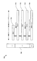
Table 1(表1)は、5、6、および20MHzに関するFFTサイズを示す。より広い、たとえば、20MHzの割振りを逐次方式で復号することも可能である。このことは、FFTサイズおよび関連したメモリを最小限に抑える。しかしながら、それはまた、ピークのビットレートを束縛し得、統合された所与の多重化内での複数のサービスにわたる復号の同時処理を制限し得る。図10は、時間および周波数にわたる概念的な統計的多重化1000を示すブロック図である。N個の復号されたサービスは、時間領域において非ブロッキングでなければならない。たとえば、サービス6a 1001の部分は、6b 1002の他の部分と時間において重複しない。高い帯域幅の多重化のためのこの漸進的な復号方法は、中電力モバイルおよび潜在的に低い電力、低いタワー、ループトップ受信のユースケースを可能にしながらモバイルデバイスにおけるさらなる複雑さを制限するので、モバイルサービスにとって望ましい解決策であり得る。
Table 1 shows the FFT sizes for 5, 6, and 20 MHz. It is also possible to decode a wider, for example, 20 MHz allocation in a sequential manner. This minimizes the FFT size and associated memory. However, it can also constrain the peak bit rate and limit the concurrent processing of decoding across multiple services within a given integrated multiplex. FIG. 10 is a block diagram illustrating conceptual
上の拡張サイクリックプレフィックスのモバイルモードは、後に続くに従って複雑さに影響を及ぼす。サポートされる総継続時間は増大されており、いくつかのモードはサブフレームに対して分数である。これらの態様はシグナリングに含まれ、最大FFTは増大する。このことは、シンボル時間+サイクリックプレフィックスの総継続時間が増大されたことの直接の結果である。新しい各総継続時間について、新たに定義されたパイロットパターンが存在する。 The mobile mode of the extended cyclic prefix above affects the complexity as it follows. The total supported duration has been increased and some modes are fractional for subframes. These aspects are included in the signaling and the maximum FFT is increased. This is a direct result of the increase in symbol time + total cyclic prefix duration. There is a newly defined pilot pattern for each new total duration.
モバイル用途のためにサポートされる現在の最大bps/Hzは、3bps/Hzよりも大きい。しかしながら、最高に可能なbps/Hz効率を実現することは、固定プロファイルを使用することを教示し、上のTable 1(表1)と比較して、総継続時間に対するパイロットオーバーヘッドの低減およびサイクリックプレフィックス継続時間の低減をもたらす。これらの高効率固定モードは、大規模な変換および狭いキャリア間隔に起因して、モバイル用途において受諾され得ないことがある。狭いキャリア間隔は、キャリア間干渉(ICI)除去なしにサポート可能な最大ドップラーレートを著しく制限する。ICIは、デバイスの複雑さを大幅に増大させる。大規模な変換も、複雑さに影響を及ぼす。モバイルの要件が、ICIなしに、または大きい固定プロファイル変換の使用なしに満たされることが好ましくあり得る。 The current maximum bps / Hz supported for mobile applications is greater than 3 bps / Hz. However, achieving the highest possible bps / Hz efficiency teaches using a fixed profile, reducing pilot overhead versus total duration and cyclic compared to Table 1 above. This results in a reduction in prefix duration. These high efficiency fixed modes may not be accepted in mobile applications due to large conversions and narrow carrier spacing. Narrow carrier spacing significantly limits the maximum Doppler rate that can be supported without inter-carrier interference (ICI) cancellation. ICI significantly increases device complexity. Large scale transformations also affect complexity. It may be preferred that mobile requirements are met without ICI or without the use of large fixed profile transformations.
図11は、本開示の一態様を実施するように実行される例示的なブロックを示す機能ブロック図である。ブロック1100において、ブロードキャストで送信されるべきOFDMAシンボルのためのサイクリックプレフィックスオーバーヘッドが選択され、サイクリックプレフィックスオーバーヘッドは、標準的なキャリア対RBの規定の整数倍に基づいて決定される。ブロードキャストは、たとえば、マルチメディアブロードキャストであってよい。整数倍を選択する際に、公称の300キャリア対25RBの規定が使用される。300キャリア対25RBの整数倍は、300キャリア対25RBの規定に従って規定されている既存のシステムでの規範的な20%のオーバーヘッドよりも小さいオーバーヘッドにおける可変サイクリックプレフィックス継続時間を可能にする。たとえば、370キャリアにおいて始まり5キャリアずつ300キャリアまで下へ順序付けするキャリア群の特有の組合せは、N×1.33%の分数レートにおけるサイクリックプレフィックスオーバーヘッドのパーセンテージの直線的な数列を有益に形成し得、ここで、Nは選択される組合せの比、たとえば、370対規範的な300キャリアの整数倍を表す。
FIG. 11 is a functional block diagram illustrating example blocks executed to implement one aspect of the present disclosure. At
ブロック1101において、サイクリックプレフィックス継続時間が、OFDMAシンボルのために選択され、サイクリックプレフィックス継続時間は、標準的なキャリア対RBの規定の整数倍に基づいて、RB当たり整数個のキャリアをもたらすように決定される。規範的な300キャリア対25RBに対して一群のキャリアが選択されると、サイクリックプレフィックス継続時間およびシンボル継続時間の総継続時間を考慮して、RB当たり整数個のキャリアを可能にするサイクリックプレフィックス継続時間のシーケンスが形成され得る。たとえば、370〜300キャリアの一群の選択を用いて、RB当たり整数個のキャリアをもたらす2.5、5、および10ミリ秒のサイクリック継続時間が形成され得る。
At
ブロック1102において、OFDMAシンボルは、サイクリックプレフィックス継続時間およびサイクリックプレフィックスオーバーヘッドを使用して送信される。
At
下のTable 2(表2)は、100μ秒よりも大きい遅延スプレッドに対するいくつかの地上放送システム要件を、いくらかのマージンを伴って満たすことができるいくつかの選択を示す。サイクリックプレフィックスの小さい比率を実現するために、公称の25RB当たり300キャリアに対するキャリアの数は、増大することになる。固定モードに関する複雑さの問題は、モバイルに対するものほど制約することはないが、FFTを32K以下に保つことは依然として望ましくあり得る。 Table 2 below shows some choices that can meet some terrestrial broadcast system requirements for delay spreads greater than 100 μs, with some margin. In order to achieve a small ratio of cyclic prefixes, the number of carriers for 300 carriers per nominal 25 RBs will increase. The complexity issues with fixed mode are not as restrictive as for mobile, but it may still be desirable to keep the FFT below 32K.
これらの可能な構成のうち2.5、5および10ミリ秒は、数秘学がRB当たり整数個のキャリアとなる結果にし得るので、潜在的に関心を引く総継続時間である。下のTable 3(表3)は、上の数秘学がリソースブロック当たり整数個のキャリアをどのようにもたらすのかを示す。RB当たりのキャリアの数は、式:
RB当たりのキャリアの数=180kHz×総継続時間×(1-分数CP) (1)
に従って計算され得る。
Of these possible configurations, 2.5, 5 and 10 milliseconds are potentially interesting total durations as numerology can result in an integer number of carriers per RB. Table 3 below shows how the above numerology yields an integer number of carriers per resource block. The number of carriers per RB is the formula:
Number of carriers per RB = 180 kHz x total duration x (1-fractional CP) (1)
Can be calculated according to
180kHzがRBの帯域幅を表す場合、総継続時間は、秒単位でのシンボル時間+サイクリックプレフィックス継続時間を含む総継続時間を表し、分数CPは、いくつかの様々な総継続時間に対してRB当たり整数個のキャリアをもたらすように選択された、自己発見的方法で決定された分数である。 When 180kHz represents RB bandwidth, the total duration represents the total duration including symbol time in seconds + cyclic prefix duration, and fractional CP is for several different total durations. A fraction determined in a self-discovering manner, chosen to yield an integer number of carriers per RB.
Table 3(表3)において特定される一群の解決策は、一連の分数、N/75に関する分数CPから得られ、ただし、Nは整数(N=1、2、3、など)である。 The group of solutions identified in Table 3 is derived from a series of fractions, a fractional CP with respect to N / 75, where N is an integer (N = 1, 2, 3, etc.).
より大きい容量を実現することはまた、公称の4.5MHz当たり25リソースブロックのサポートを越えて、スペクトル占有を増大させることを含み得る。キャリア対リソースブロックの整数の関係により、この処理は簡略化される。各RBが5MHzの3.6%であるので、合計27RBを得るためにさらなる2つのリソースブロックを追加することによって、全利用率を7.2%だけ97.2%まで増大させることは妥当であり得る。さらなる新しい固定プロファイルの変調コーディング方式(MCS)が、4bps/Hzよりも多くを実現するために使用され得る。Table 3(表3)は、容量獲得コードを想定してサポートされるbps/Hzおよび最小の付加白色ガウス雑音(AWGN)のC/Nを示す。 Achieving larger capacity may also include increasing the spectrum occupancy beyond the support of 25 resource blocks per nominal 4.5 MHz. This process is simplified by the integer relationship of carrier to resource block. Since each RB is 3.6% of 5 MHz, it may be reasonable to increase the total utilization rate by 7.2% to 97.2% by adding two more resource blocks to obtain a total of 27 RBs. A further new fixed profile modulation coding scheme (MCS) may be used to achieve more than 4 bps / Hz. Table 3 shows the C / N of bps / Hz and minimum additive white Gaussian noise (AWGN) supported assuming capacity acquisition code.
2.5ミリ秒に対してRB当たり6個のパイロットを割り振り平均することによって、1.37%の総パイロット電力を得ることが可能である。下のTable 4(表4)は、目標効率を達成するためのリソースの最終的な割振りを示し、他の組合せが可能である。 By assigning and averaging 6 pilots per RB for 2.5 milliseconds, it is possible to obtain a total pilot power of 1.37%. Table 4 below shows the final allocation of resources to achieve the target efficiency and other combinations are possible.
Table 4(表4)は、5MHzにおける固定サービスのためのMCSの選択を示す。これらの固定プロファイルのキャリアの特徴は、後続する漸進的な方式としての設計に影響を及ぼす。27RBのベースバンド帯域幅を可能にするように修正されたベースバンドアームフィルタが必要である。各総継続時間について新しいパイロットパターンが存在する。各分数サイクリックプレフィックスに対して、修正された数秘学が存在する。最大限必要とされるFFTは、上述されたモバイルのための拡張に比べてさらに増大されている。 Table 4 shows the MCS selection for fixed services at 5 MHz. The characteristics of these fixed profile carriers influence the design as a subsequent progressive scheme. A baseband arm filter modified to allow a baseband bandwidth of 27RB is needed. There is a new pilot pattern for each total duration. There is a modified numerology for each fractional cyclic prefix. The maximum required FFT is further increased compared to the expansion for mobile described above.
分数CPのための一群の解決策は、75の分母に基づいて、2.5、5、および10ミリ秒の総継続時間に対して、RB当たり整数個のキャリアを実現する。しかしながら、本開示の様々な態様は、1から10ミリ秒までの総継続時間における各整数ミリ秒に対して、RB当たり整数のキャリアを実現し得る。継続時間のこの範囲にわたる整数キャリアは、0.5555%のステップで変化する。したがって、75の分母を使用して生み出される一群よりも大きい柔軟性をもたらす。様々な態様は、任意の整数Nについて、分母が180の分数(N/180)に基づいて分数CPを修正することによってこの目的を達成する。N=36を選択することは、たとえば、Table 1(表1)の16.66μ秒および33.33μ秒の総継続時間において規定されるように、Table 1(表1)に関して示すような公称の20%分数CPを実現するはずであることに留意されたい。 A group of solutions for fractional CP, based on 75 denominators, achieves an integer number of carriers per RB for a total duration of 2.5, 5, and 10 milliseconds. However, various aspects of the present disclosure may achieve an integer number of carriers per RB for each integer milliseconds in a total duration from 1 to 10 milliseconds. The integer carrier over this range of duration varies in 0.5555% steps. Thus, it provides greater flexibility than the group produced using the 75 denominator. Various aspects achieve this goal by modifying the fractional CP for any integer N based on a fraction with a denominator of 180 (N / 180). Choosing N = 36 is, for example, nominal 20% as shown for Table 1 (Table 1), as specified in the total duration of 16.66 μsec and 33.33 μsec in Table 1. Note that a fractional CP should be realized.
図12は、本開示の一態様を実施するように実行される例示的なブロックを示す機能ブロック図である。ブロック1200において、ブロードキャストで送信されるべきOFDMAシンボルのためのサイクリックプレフィックスオーバーヘッドが選択され、サイクリックプレフィックスオーバーヘッドは、分母が180の分数サイクリックプレフィックスに基づいて決定される。分数CPのサイクリックプレフィックスオーバーヘッドを決定するために特有の分数は、適切な整数N、すなわち複数の単位分数1/180(0.5555%)を選択することによって選択され得る。
FIG. 12 is a functional block diagram illustrating example blocks executed to implement one aspect of the present disclosure. At
ブロック1201において、OFDMAシンボルのための総継続時間が選択され、総継続時間は、RB当たり整数個のキャリアをもたらすように決定される。総継続時間は、シンボルの継続時間または時間と、サイクリックプレフィックス継続時間との合計を表す。1ミリ秒のサブフレームに基づくLTE送信構造を用いて、1ミリ秒〜10ミリ秒の任意の整数の総継続時間が選択され得、依然としてRB当たり所望の整数個のキャリアを実現し得る。
At
ブロック1202において、OFDMAシンボルは、総継続時間およびサイクリックプレフィックスオーバーヘッドを使用して送信される。
At
ブロードキャストが標準的なシステムブロードキャストであってよく、またはマルチメディアブロードキャストであってもよいことに留意されたい。本開示は、サイクリックプレフィックスオーバーヘッドの送信にとって、特定のタイプのブロードキャストに限定されない。 Note that the broadcast may be a standard system broadcast or may be a multimedia broadcast. The present disclosure is not limited to a specific type of broadcast for cyclic prefix overhead transmission.
Table 5(表5)は、式(1)に従って1/180の分数の整数倍によって推進される、一群の解決策を利用する本開示の様々な態様から得られるRB当たりのキャリアの数を示す。 Table 5 shows the number of carriers per RB obtained from various aspects of the present disclosure utilizing a group of solutions driven by an integer multiple of 1/180 fraction according to equation (1). .
選択された態様では、256直交振幅変調(QAM)の使用が、LTEにおけるユニキャスト送信のために採用され得る。このことは、LTEブロードキャスト用途のために256QAMを利用するための機会を開くことになる。しかしながら、15dBは効率よく利用されるには低すぎることがあるので、256QAMの利用可能性は、15dBのC/Nにおける大きいbps/Hzの要件を満たすことに関して、いかなる本質的な利点ももたらし得ない。しかしながら、デバイスの中で利用されるADCによって課せられる信号対ノイズの制限が著しく改善されなければならないことがあるという観点から、LTEデバイスのインフラストラクチャにおいて256QAMを導入することは有益であり得る。LTEブロードキャストは、256QAMモードがLTEブロードキャストのために採用されるかどうかとは無関係に、256QAMユニキャストが存在することから恩恵を受ける。256QAMのLTEブロードキャストモードのサポートは、64QAMについて上述された数秘学に基づいて可能であり得る。 In selected aspects, the use of 256 quadrature amplitude modulation (QAM) may be employed for unicast transmission in LTE. This opens up opportunities for using 256QAM for LTE broadcast applications. However, since 15dB may be too low to be used efficiently, the availability of 256QAM can provide any inherent advantage in meeting the high bps / Hz requirement at 15dB C / N. Absent. However, it may be beneficial to introduce 256QAM in the LTE device infrastructure in view of the signal-to-noise limitations imposed by the ADCs utilized in the device may have to be significantly improved. LTE broadcasts benefit from the presence of 256QAM unicast, regardless of whether 256QAM mode is adopted for LTE broadcasts. Support for 256QAM LTE broadcast mode may be possible based on the numerology described above for 64QAM.
既存のプライマリ同期信号(PSS)/セカンダリ同期信号(SSS)/物理ブロードキャストチャネル(PBCH)/システム情報ブロック(SIB)の送信フォーマットは、追加された物理レイヤの特徴を記述するために十分であり得る。すべてのそのような情報を搬送するために、1つのSIBのみが必要とされ得る。送信帯域にリンクされた半静的なSIBスケジューリングが適用され得る。そうはいっても、ここで5MHzまたは6MHzのいずれかが説明されたユースケースでは、各周波数セグメントは、多重化のすべての周波数セグメントにおけるトラフィックを記述するべきである。異なるMBSFNエリアは、異なるサイクリックプレフィックスの長さをサポートし得、そのような情報は、SIBの中で示される。異なるサブフレーム構造は、異なる各サイクリックプレフィックスの長さについて導入される。 The transmission format of the existing primary synchronization signal (PSS) / secondary synchronization signal (SSS) / physical broadcast channel (PBCH) / system information block (SIB) may be sufficient to describe the characteristics of the added physical layer . Only one SIB may be required to carry all such information. Semi-static SIB scheduling linked to the transmission band may be applied. Nevertheless, in the use case described here for either 5 MHz or 6 MHz, each frequency segment should describe traffic in all frequency segments of the multiplex. Different MBSFN areas may support different cyclic prefix lengths, and such information is indicated in the SIB. Different subframe structures are introduced for each different cyclic prefix length.
情報および信号は、様々な異なる技術および技法のいずれかを使用して表され得ることを、当業者は理解されよう。たとえば上記説明全体を通して参照されてよいデータ、命令、指令、情報、信号、ビット、記号およびチップは、電圧、電流、電磁波、磁界または粒子、光学場または粒子、あるいはそれらの任意の組合せによって表されてもよい。 Those of skill in the art will understand that information and signals may be represented using any of a variety of different technologies and techniques. For example, data, instructions, commands, information, signals, bits, symbols and chips that may be referred to throughout the above description are represented by voltage, current, electromagnetic waves, magnetic fields or particles, optical fields or particles, or any combination thereof. May be.
本明細書の開示に関して説明された様々な例示的論理ブロック、モジュール、回路、および処理ステップは、電子ハードウェア、コンピュータソフトウェア、またはその両方の組合せとして実装されてもよいことが、当業者にはさらに諒解されよう。ハードウェアおよびソフトウェアのこの互換性を明確に説明するために、様々な例示的な構成要素、ブロック、モジュール、回路、およびステップが、それらの機能の観点から一般的に上記で説明されている。そのような機能がハードウェアまたはソフトウェアのどちらとして実施されるのかは、システム全体に課される特定の用途および設計制約に依存する。当業者は、説明した機能を特定の適用例ごとに様々な方法で実装し得るが、そのような実装の決定は、本開示の範囲からの逸脱をもたらすものと解釈されるべきではない。 Those skilled in the art will appreciate that the various exemplary logic blocks, modules, circuits, and processing steps described in connection with the disclosure herein may be implemented as electronic hardware, computer software, or a combination of both. It will be further understood. To clearly illustrate this interchangeability of hardware and software, various illustrative components, blocks, modules, circuits, and steps have been described above generally in terms of their functionality. Whether such functionality is implemented as hardware or software depends upon the particular application and design constraints imposed on the overall system. Those skilled in the art may implement the described functionality in a variety of ways for each particular application, but such implementation decisions should not be construed as causing a departure from the scope of the present disclosure.
本明細書において開示に関連して説明された様々な例示的な論理ブロック、モジュール、および回路は、汎用プロセッサ、デジタル信号プロセッサ(DSP)、特定用途向け集積回路(ASIC)、フィールドプログラマブルゲートアレイ(FPGA)またはその他のプログラマブル論理デバイス、ディスクリートゲートまたはトランジスタ論理、ディスクリートハードウェアコンポーネント、または本明細書において説明される機能を実行するように設計されたこれらの任意の組合せにより実装または実行されてもよい。汎用プロセッサはマイクロプロセッサであってもよいが、代替ではプロセッサは、任意の従来のプロセッサ、コントローラ、マイクロコントローラまたはステートマシンであってもよい。プロセッサは、たとえばDSPとマイクロプロセッサの組合せ、複数のマイクロプロセッサ、DSPコアと連結した1つまたは複数のマイクロプロセッサ、または任意の他のそのような構成など、コンピューティングデバイスの組合せとしても実装され得る。 Various exemplary logic blocks, modules, and circuits described in connection with the disclosure herein include general purpose processors, digital signal processors (DSPs), application specific integrated circuits (ASICs), field programmable gate arrays ( FPGA) or other programmable logic device, discrete gate or transistor logic, discrete hardware components, or any combination thereof designed to perform the functions described herein . A general purpose processor may be a microprocessor, but in the alternative, the processor may be any conventional processor, controller, microcontroller, or state machine. A processor may also be implemented as a combination of computing devices, such as a combination of DSP and microprocessor, multiple microprocessors, one or more microprocessors coupled to a DSP core, or any other such configuration. .
本明細書において開示に関連して説明された方法またはプロセスのステップは、ハードウェアにおいて、プロセッサによって実行されるソフトウェアモジュールにおいて、またはこの2つの組合せにおいて直接具現されてもよい。ソフトウェアモジュールは、RAMメモリ、フラッシュメモリ、ROMメモリ、EPROMメモリ、EEPROMメモリ、レジスタ、ハードディスク、リムーバブルディスク、CD-ROM、または当技術分野で知られているその他の形態の記憶媒体に、常駐することができる。例示的記憶媒体がプロセッサに結合され、プロセッサが記憶媒体から情報を読み取ること、および記憶媒体に情報を書き込むことができるようにする。代替として、記憶媒体はプロセッサと一体化され得る。プロセッサおよび記憶媒体は、ASIC内に存在し得る。ASICは、ユーザ端末内に存在してもよい。代替で、プロセッサおよび記憶媒体は、ユーザ端末内の個別の構成要素として存在してもよい。 The method or process steps described in connection with the disclosure herein may be implemented directly in hardware, in software modules executed by a processor, or in a combination of the two. Software modules reside in RAM memory, flash memory, ROM memory, EPROM memory, EEPROM memory, registers, hard disks, removable disks, CD-ROMs, or other forms of storage media known in the art Can do. An exemplary storage medium is coupled to the processor such that the processor can read information from, and write information to, the storage medium. In the alternative, the storage medium may be integral to the processor. The processor and the storage medium may reside in an ASIC. The ASIC may be present in the user terminal. In the alternative, the processor and the storage medium may reside as discrete components in a user terminal.
1つまたは複数の例示的設計では、記載された機能は、ハードウェア、ソフトウェア、ファームウェア、またはその任意の組合せにおいて実装されてもよい。ソフトウェアで実装される場合、機能は、1つまたは複数の命令またはコードとして、コンピュータ可読媒体上に記憶され得るか、またはコンピュータ可読媒体を介して送信され得る。コンピュータ可読記憶媒体は、汎用または特殊用途コンピュータによってアクセスできる任意の利用可能な媒体とすることができる。限定的ではなく、一例として、そのようなコンピュータ可読記憶媒体は、RAM、ROM、EEPROM、CD-ROMもしくはその他の光ディスク記憶装置、磁気ディスク記憶装置もしくはその他の磁気記憶装置、または望ましいプログラムコード手段を命令またはデータ構造の形態で搬送または記憶するために使用され得る、汎用もしくは特殊用途コンピュータ、または汎用もしくは特殊用途プロセッサによってアクセスされ得る任意の他の媒体を備えることができる。また、非一時的接続は、コンピュータ可読媒体の定義内に適切に含まれ得る。たとえば、命令が、同軸ケーブル、光ファイバケーブル、ツイストペア、またはデジタル加入者回線(DSL)を使用して、ウェブサイト、サーバ、または他のリモートソースから送信される場合、同軸ケーブル、光ファイバケーブル、ツイストペア、またはDSLは、媒体の定義に含まれる。ディスク(disk)およびディスク(disc)は、本明細書において使用されるときに、コンパクトディスク(disc)(CD)、レーザーディスク(登録商標)(disc)、光ディスク(disc)、デジタル多用途ディスク(disc)(DVD)、フロッピー(登録商標)ディスク(disk)およびブルーレイディスク(disc)を含み、ディスク(disk)は通常、データを磁気的に再生し、一方、ディスク(disc)は、レーザーを用いてデータを光学的に再生する。上記のものの組合せもまた、コンピュータ可読媒体の範囲内に含まれるべきである。 In one or more exemplary designs, the functions described may be implemented in hardware, software, firmware, or any combination thereof. If implemented in software, the functions may be stored on or transmitted over as one or more instructions or code on a computer-readable medium. Computer readable storage media can be any available media that can be accessed by a general purpose or special purpose computer. By way of example, and not limitation, such computer-readable storage media includes RAM, ROM, EEPROM, CD-ROM or other optical disk storage, magnetic disk storage or other magnetic storage, or desirable program code means. It may comprise a general purpose or special purpose computer, or any other medium that can be accessed by a general purpose or special purpose processor, which may be used for carrying or storing in the form of instructions or data structures. Non-transitory connections may also be appropriately included within the definition of a computer readable medium. For example, if instructions are sent from a website, server, or other remote source using coaxial cable, fiber optic cable, twisted pair, or digital subscriber line (DSL), coaxial cable, fiber optic cable, Twisted pair, or DSL, is included in the media definition. Discs and discs, as used herein, are compact discs (CD), laser discs (discs), optical discs, digital versatile discs ( disc) (DVD), floppy disk, and Blu-ray disc, which typically reproduces data magnetically, while the disc uses a laser To optically reproduce the data. Combinations of the above should also be included within the scope of computer-readable media.
本開示の先の説明は、いかなる当業者も本開示を作製または使用できるようにするために提供される。本開示への様々な修正が当業者には容易に明らかになり、本明細書で定義される一般原理は、本開示の趣旨または範囲から逸脱することなく、他の変形形態に適用され得る。したがって、本開示は、本明細書で説明される例および設計に限定されるものではなく、本明細書で開示される原理および新規の特徴に一致する最大の範囲を与えられるものである。 The previous description of the disclosure is provided to enable any person skilled in the art to make or use the disclosure. Various modifications to the present disclosure will be readily apparent to those skilled in the art and the generic principles defined herein may be applied to other variations without departing from the spirit or scope of the disclosure. Accordingly, the present disclosure is not limited to the examples and designs described herein but is to be accorded the maximum scope consistent with the principles and novel features disclosed herein.
100 発展型パケットシステム
102 UE
104 発展型UMTS地上波無線アクセスネットワーク
106 eNB
108 他のeNB
110 発展型パケットコア
112 モビリティ管理エンティティ
114 他のMME
116 サービングゲートウェイ
118 パケットデータネットワークゲートウェイ
120 ホーム加入者サーバ
122 事業者のインターネットプロトコルサービス
124 ワイヤレス通信システム
126 ユーザ機器
128 eノードB
130 マルチキャスト協調エンティティ
132 モビリティ管理エンティティ
134 パケットデータネットワークゲートウェイ
136 ブロードキャストマルチキャストサービスセンタ
138 コンテンツプロバイダサーバ
140 MBMSゲートウェイ
142 サービング汎用パケット無線サービスサポートノード
144 UTRAN無線ネットワークコントローラ
146 UEモバイルエンティティ
200 アクセスネットワーク
202 セル
204 マクロeNB
206 UE
208 低電力クラスeNB
210 セルラー領域
302 セル固有RS
304 UE固有RS
430 物理ランダムアクセスチャネル
506 物理レイヤ
508 L2レイヤ
510 媒体アクセス制御サブレイヤ
512 無線リンク制御サブレイヤ
514 パケットデータコンバージェンスプロトコルサブレイヤ
516 無線リソース制御サブレイヤ
610 eNB
616 送信プロセッサ
618 送信機
620 アンテナ
650 UE
652 アンテナ
654 受信機
656 受信プロセッサ
658 チャネル推定器
659 コントローラ/プロセッサ
660 メモリ
662 データシンク
667 データソース
668 TXプロセッサ
670 RXプロセッサ
674 チャネル推定器
675 コントローラ/プロセッサ
676 メモリ
802 eNB
804 UE
806 物体
808 直接伝搬経路
810 間接伝搬経路
100 Advanced packet system
102 UE
104 Advanced UMTS Terrestrial Radio Access Network
106 eNB
108 other eNB
110 Advanced Packet Core
112 Mobility management entity
114 Other MMEs
116 Serving gateway
118 packet data network gateway
120 Home subscriber server
122 Provider Internet Protocol Service
124 wireless communication system
126 User equipment
128 eNodeB
130 Multicast Coordination Entities
132 Mobility management entity
134 packet data network gateway
136 Broadcast Multicast Service Center
138 Content Provider Server
140 MBMS gateway
142 Serving General Packet Radio Service Support Node
144 UTRAN wireless network controller
146 UE Mobile Entity
200 access network
202 cells
204 Macro eNB
206 UE
208 Low power class eNB
210 Cellular area
302 Cell-specific RS
304 UE specific RS
430 physical random access channel
506 Physical layer
508 L2 layer
510 Media Access Control Sublayer
512 Radio link control sublayer
514 Packet Data Convergence Protocol Sublayer
516 Radio Resource Control Sublayer
610 eNB
616 transmit processor
618 transmitter
620 antenna
650 UE
652 Antenna
654 receiver
656 receive processor
658 channel estimator
659 Controller / Processor
660 memory
662 Data Sync
667 data sources
668 TX processor
670 RX processor
674 channel estimator
675 Controller / Processor
676 memory
802 eNB
804 UE
806 objects
808 Direct propagation path
810 Indirect propagation path
Claims (30)
前記OFDMAシンボルのためのサイクリックプレフィックス継続時間を選択するステップであって、前記サイクリックプレフィックス継続時間は、前記標準的なキャリア対RBの規定の前記整数倍に基づいて、RB当たり整数個のキャリアをもたらすように決定されるステップと、
前記サイクリックプレフィックス継続時間およびサイクリックプレフィックスオーバーヘッドを使用して前記OFDMAシンボルを送信するステップと
を備えるワイヤレス通信の方法。 Selecting a cyclic prefix overhead for orthogonal division multiple access (OFDMA) symbols to be transmitted in broadcast, wherein the cyclic prefix overhead is a specified integer number of standard carrier-to-resource blocks (RB) Steps determined on the basis of times,
Selecting a cyclic prefix duration for the OFDMA symbol, the cyclic prefix duration being an integer number of carriers per RB based on the integer multiple of the standard carrier-to-RB definition Steps determined to yield,
Transmitting the OFDMA symbol using the cyclic prefix duration and a cyclic prefix overhead.
RB当たりのキャリアの数=180,000(Hz)×総継続時間(秒)(1-分数サイクリックプレフィックス)に従って決定され、180,000(Hz)はRBの帯域幅を表し、前記総継続時間(秒単位)はOFDMAシンボル時間と前記サイクリックプレフィックス継続時間との合計を表す、
請求項2に記載の方法。 The integer number of carriers per RB is the formula:
Number of carriers per RB = 180,000 (Hz) x total duration (seconds) (1-fractional cyclic prefix) determined according to 180,000 (Hz) represents RB bandwidth, the total duration (in seconds) Represents the sum of the OFDMA symbol time and the cyclic prefix duration,
The method of claim 2.
分数サイクリックプレフィックス=N/180に従って決定され、Nは整数値を表す、
請求項2に記載の方法。 The fractional cyclic prefix has the formula:
Determined according to the fractional cyclic prefix = N / 180, where N represents an integer value,
The method of claim 2.
シンボル継続時間と、複数のサイクリックプレフィックス継続時間のうちの1つとを含む所望の継続時間を選択するステップを備え、前記選択された所望の継続時間は、RB当たり前記整数個のキャリアをもたらす、
請求項2に記載の方法。 The step of selecting the total duration comprises:
Selecting a desired duration comprising a symbol duration and one of a plurality of cyclic prefix durations, the selected desired duration yielding the integer number of carriers per RB;
The method of claim 2.
公称の25RB当たり300キャリアに対して整数個のキャリアをもたらすように選択されるキャリア数を備え、前記選択されたキャリア数は、前記選択されたキャリア数に従って前記サイクリックプレフィックス継続時間が変化することを可能にする、
請求項1に記載の方法。 The integer multiple is
With a number of carriers selected to provide an integer number of carriers for 300 carriers per nominal 25 RBs, the number of selected carriers varying according to the cyclic prefix duration according to the number of selected carriers Enable,
The method of claim 1.
シンボル継続時間と、複数のサイクリックプレフィックス継続時間のうちの1つとを含む所望の継続時間を選択するステップを備え、前記選択された所望の継続時間は、RB当たり前記整数個のキャリアをもたらす、
請求項1に記載の方法。 The step of selecting the cyclic prefix duration is:
Selecting a desired duration comprising a symbol duration and one of a plurality of cyclic prefix durations, the selected desired duration yielding the integer number of carriers per RB;
The method of claim 1.
前記OFDMAシンボルのためのサイクリックプレフィックス継続時間を選択するための手段であって、前記サイクリックプレフィックス継続時間は、前記標準的なキャリア対RBの規定の前記整数倍に基づいて、RB当たり整数個のキャリアをもたらすように決定される手段と、
前記サイクリックプレフィックス継続時間およびサイクリックプレフィックスオーバーヘッドを使用して前記OFDMAシンボルを送信するための手段と
を備えるワイヤレス通信のために構成された装置。 A means for selecting a cyclic prefix overhead for orthogonal division multiple access (OFDMA) symbols to be transmitted in broadcast, wherein the cyclic prefix overhead is defined in a standard carrier-to-resource block (RB) Means determined on the basis of an integer multiple of
Means for selecting a cyclic prefix duration for the OFDMA symbol, wherein the cyclic prefix duration is an integer number per RB based on the integer multiple of the standard carrier-to-RB specification. Means determined to bring about a career,
Means for transmitting said OFDMA symbol using said cyclic prefix duration and cyclic prefix overhead.
シンボル継続時間と、複数のサイクリックプレフィックス継続時間のうちの1つとを含む所望の継続時間を選択するための手段を備え、前記選択された所望の継続時間は、RB当たり前記整数個のキャリアをもたらす、
請求項14に記載の装置。 Said means for selecting the total duration is:
Means for selecting a desired duration including a symbol duration and one of a plurality of cyclic prefix durations, the selected desired duration comprising the integer number of carriers per RB. Bring,
15. An apparatus according to claim 14.
公称の25RB当たり300キャリアに対して整数個のキャリアをもたらすように選択されるキャリア数を備え、前記選択されたキャリア数は、前記選択されたキャリア数に従って前記サイクリックプレフィックス継続時間が変化することを可能にする、
請求項13に記載の装置。 The integer multiple is
With a number of carriers selected to provide an integer number of carriers for 300 carriers per nominal 25 RBs, the number of selected carriers varying according to the cyclic prefix duration according to the number of selected carriers Enable,
The apparatus according to claim 13.
シンボル継続時間と、複数のサイクリックプレフィックス継続時間のうちの1つとを含む所望の継続時間を選択するための手段を備え、前記選択された所望の継続時間は、RB当たり前記整数個のキャリアをもたらす、
請求項13に記載の装置。 The means for selecting the cyclic prefix duration is:
Means for selecting a desired duration including a symbol duration and one of a plurality of cyclic prefix durations, the selected desired duration comprising the integer number of carriers per RB. Bring,
The apparatus according to claim 13.
コンピュータに、ブロードキャストで送信されるべき直交分割多元接続(OFDMA)シンボルのためのサイクリックプレフィックスオーバーヘッドを選択させるためのプログラムコードであって、前記サイクリックプレフィックスオーバーヘッドは、標準的なキャリア対リソースブロック(RB)の規定の整数倍に基づいて決定されるプログラムコードと、
前記コンピュータに、前記OFDMAシンボルのためのサイクリックプレフィックス継続時間を選択させるためのプログラムコードであって、前記サイクリックプレフィックス継続時間は、前記標準的なキャリア対RBの規定の前記整数倍に基づいて、RB当たり整数個のキャリアをもたらすように決定されるプログラムコードと、
前記コンピュータに、前記サイクリックプレフィックス継続時間およびサイクリックプレフィックスオーバーヘッドを使用して前記OFDMAシンボルを送信させるためのプログラムコードと
を備える、非一時的コンピュータ可読媒体。 A non-transitory computer readable medium having program code recorded thereon, wherein the program code is
Program code for causing a computer to select a cyclic prefix overhead for an orthogonal division multiple access (OFDMA) symbol to be transmitted in broadcast, wherein the cyclic prefix overhead is a standard carrier-to-resource block ( (RB) a program code determined based on a specified integer multiple of
Program code for causing the computer to select a cyclic prefix duration for the OFDMA symbol, wherein the cyclic prefix duration is based on the integer multiple of the standard carrier-to-RB definition Program code determined to yield an integer number of carriers per RB, and
A non-transitory computer-readable medium comprising: program code for causing the computer to transmit the OFDMA symbol using the cyclic prefix duration and a cyclic prefix overhead.
前記コンピュータに、シンボル継続時間と、複数のサイクリックプレフィックス継続時間のうちの1つとを含む所望の継続時間を選択させるためのプログラムコードを備え、前記選択された所望の継続時間は、RB当たり前記整数個のキャリアをもたらす、
請求項19に記載の非一時的コンピュータ可読媒体。 The program code for causing the computer to select a total duration is:
Program code for causing the computer to select a desired duration including a symbol duration and one of a plurality of cyclic prefix durations, the selected desired duration per the RB Yield an integer number of carriers,
20. A non-transitory computer readable medium according to claim 19.
公称の25RB当たり300キャリアに対して整数個のキャリアをもたらすように選択されるキャリア数を備え、前記選択されたキャリア数は、前記選択されたキャリア数に従って前記サイクリックプレフィックス継続時間が変化することを可能にする、
請求項18に記載の非一時的コンピュータ可読媒体。 The integer multiple is
With a number of carriers selected to provide an integer number of carriers for 300 carriers per nominal 25 RBs, the number of selected carriers varying according to the cyclic prefix duration according to the number of selected carriers Enable,
19. A non-transitory computer readable medium according to claim 18.
前記コンピュータに、シンボル継続時間と、複数のサイクリックプレフィックス継続時間のうちの1つとを含む所望の継続時間を選択させるためのプログラムコードを備え、前記選択された所望の継続時間は、RB当たり前記整数個のキャリアをもたらす、
請求項18に記載の非一時的コンピュータ可読媒体。 The program code for causing the computer to select the cyclic prefix duration is:
Program code for causing the computer to select a desired duration including a symbol duration and one of a plurality of cyclic prefix durations, the selected desired duration per the RB Yield an integer number of carriers,
19. A non-transitory computer readable medium according to claim 18.
少なくとも1つのプロセッサと、
前記少なくとも1つのプロセッサに結合されたメモリとを含み、
前記少なくとも1つのプロセッサは、
ブロードキャストで送信されるべき直交分割多元接続(OFDMA)シンボルのためのサイクリックプレフィックスオーバーヘッドを選択することであって、前記サイクリックプレフィックスオーバーヘッドは、標準的なキャリア対リソースブロック(RB)の規定の整数倍に基づいて決定されることと、
前記OFDMAシンボルのためのサイクリックプレフィックス継続時間を選択することであって、前記サイクリックプレフィックス継続時間は、前記標準的なキャリア対RBの規定の前記整数倍に基づいて、RB当たり整数個のキャリアをもたらすように決定されることと、
前記サイクリックプレフィックス継続時間およびサイクリックプレフィックスオーバーヘッドを使用して前記OFDMAシンボルを送信することと
を行うように構成された装置。 A device configured for wireless communication,
At least one processor;
And a memory coupled to the at least one processor,
The at least one processor is
Selecting a cyclic prefix overhead for an orthogonal division multiple access (OFDMA) symbol to be transmitted in broadcast, wherein the cyclic prefix overhead is a specified integer number of standard carrier-to-resource block (RB) To be determined based on the fold,
Selecting a cyclic prefix duration for the OFDMA symbol, wherein the cyclic prefix duration is an integer number of carriers per RB based on the integer multiple of the standard carrier-to-RB definition. To be determined to bring
Transmitting the OFDMA symbol using the cyclic prefix duration and a cyclic prefix overhead.
RB当たりのキャリアの数=180,000(Hz)×総継続時間(秒)(1-分数サイクリックプレフィックス)に従って決定され、180,000(Hz)はRBの帯域幅を表し、前記総継続時間(秒単位)はOFDMAシンボル時間と前記サイクリックプレフィックス継続時間との合計を表す、
請求項24に記載の装置。 The integer number of carriers per RB is the formula:
Number of carriers per RB = 180,000 (Hz) x total duration (seconds) (1-fractional cyclic prefix) determined according to 180,000 (Hz) represents RB bandwidth, the total duration (in seconds) Represents the sum of the OFDMA symbol time and the cyclic prefix duration,
25. The device according to claim 24.
分数サイクリックプレフィックス=N/180に従って決定され、Nは整数値を表す、
請求項24に記載の装置。 The fractional cyclic prefix has the formula:
Determined according to the fractional cyclic prefix = N / 180, where N represents an integer value,
25. The device according to claim 24.
公称の25RB当たり300キャリアに対して整数個のキャリアをもたらすように選択されるキャリア数を備え、前記選択されたキャリア数は、前記選択されたキャリア数に従って前記サイクリックプレフィックス継続時間が変化することを可能にする、
請求項23に記載の装置。 The integer multiple is
With a number of carriers selected to provide an integer number of carriers for 300 carriers per nominal 25 RBs, the number of selected carriers varying according to the cyclic prefix duration according to the number of selected carriers Enable,
24. The apparatus of claim 23.
Applications Claiming Priority (7)
| Application Number | Priority Date | Filing Date | Title |
|---|---|---|---|
| US201361877864P | 2013-09-13 | 2013-09-13 | |
| US61/877,864 | 2013-09-13 | ||
| US201361883820P | 2013-09-27 | 2013-09-27 | |
| US61/883,820 | 2013-09-27 | ||
| US14/480,897 | 2014-09-09 | ||
| US14/480,897 US9325552B2 (en) | 2013-09-13 | 2014-09-09 | Extended duration cyclic prefix with low overhead for LTE broadcast |
| PCT/US2014/054956 WO2015038621A1 (en) | 2013-09-13 | 2014-09-10 | Extended duration cyclic prefix with low overhead for lte broadcast |
Publications (2)
| Publication Number | Publication Date |
|---|---|
| JP2016533139A true JP2016533139A (en) | 2016-10-20 |
| JP2016533139A5 JP2016533139A5 (en) | 2017-10-05 |
Family
ID=51688400
Family Applications (1)
| Application Number | Title | Priority Date | Filing Date |
|---|---|---|---|
| JP2016542066A Pending JP2016533139A (en) | 2013-09-13 | 2014-09-10 | Cyclic prefix with low overhead and extended duration for LTE broadcast |
Country Status (6)
| Country | Link |
|---|---|
| US (1) | US9325552B2 (en) |
| EP (1) | EP3044922B1 (en) |
| JP (1) | JP2016533139A (en) |
| KR (1) | KR102226787B1 (en) |
| CN (1) | CN105519066B (en) |
| WO (1) | WO2015038621A1 (en) |
Cited By (1)
| Publication number | Priority date | Publication date | Assignee | Title |
|---|---|---|---|---|
| JP2021507606A (en) * | 2017-12-18 | 2021-02-22 | 京セラ株式会社 | Improving the power consumption efficiency of MTC devices by using a common wakeup signal |
Families Citing this family (10)
| Publication number | Priority date | Publication date | Assignee | Title |
|---|---|---|---|---|
| EP3128795B1 (en) * | 2014-04-28 | 2021-07-07 | Huawei Technologies Co., Ltd. | Mbsfn configuration method and device |
| US9722848B2 (en) | 2014-05-08 | 2017-08-01 | Intel Corporation | Techniques for using a modulation and coding scheme for downlink transmissions |
| CA3060532C (en) | 2014-08-07 | 2022-03-15 | ONE Media, LLC | Dynamic configuration of a flexible orthogonal frequency division multiplexing phy transport data frame |
| WO2016022287A1 (en) | 2014-08-07 | 2016-02-11 | Coherent Logix, Incorporated | Multi-partition radio frames |
| NZ737774A (en) | 2015-06-22 | 2019-08-30 | Ericsson Telefon Ab L M | Control of timing for mixed-mode multicarrier modulation |
| WO2017086570A1 (en) * | 2015-11-20 | 2017-05-26 | 엘지전자 주식회사 | Method for performing communication using tdd frame in wireless communication system, and device therefor |
| CN113225147A (en) * | 2018-05-07 | 2021-08-06 | 中兴通讯股份有限公司 | Method, device and system for measuring total radiation power of array antenna |
| WO2020017885A1 (en) * | 2018-07-17 | 2020-01-23 | 엘지전자 주식회사 | Method and device for determining tbs in nr v2x |
| CN109286591B (en) * | 2018-09-20 | 2020-06-12 | 北京邮电大学 | Method and device for generating communication and navigation integrated fusion signal |
| CN114598390B (en) * | 2022-02-09 | 2023-09-29 | 中国计量大学 | OFDM satellite laser communication system and method with multiple-transmit-multiple-receive space-frequency block codes |
Citations (4)
| Publication number | Priority date | Publication date | Assignee | Title |
|---|---|---|---|---|
| JP2009528004A (en) * | 2006-02-21 | 2009-07-30 | クゥアルコム・インコーポレイテッド | Flexible time-frequency multiplexing configuration for wireless communication |
| JP2011504018A (en) * | 2007-11-09 | 2011-01-27 | ゼットティーイー ユー.エス.エー. インコーポレイテッド | Flexible OFDM / OFDMA frame structure for communication system |
| JP2012529193A (en) * | 2009-05-29 | 2012-11-15 | ゼットティーイー(ユーエスエー) インコーポレイテッド | Signal transmission at fixed subcarrier intervals in an OFDMA communication system |
| WO2013116237A1 (en) * | 2012-01-30 | 2013-08-08 | Qualcomm Incorporated | Cyclic prefix in evolved multimedia broadcast multicast service with high transmit power |
Family Cites Families (8)
| Publication number | Priority date | Publication date | Assignee | Title |
|---|---|---|---|---|
| US8089855B2 (en) * | 2004-06-04 | 2012-01-03 | Qualcomm Incorporated | Transmission of overhead information for broadcast and multicast services in a wireless communication system |
| US7602855B2 (en) * | 2005-04-01 | 2009-10-13 | Interdigital Technology Corporation | Method and apparatus for singular value decomposition of a channel matrix |
| GB2464244B (en) * | 2007-08-21 | 2012-01-18 | Agency Science Tech & Res | Method and system for determining whether a transmitted data signal comprising a cyclic prefix is present in a received signal |
| CN101855880A (en) * | 2007-10-17 | 2010-10-06 | 中兴通讯美国公司 | Ofdm/ofdma frame structure for communication systems |
| US8369301B2 (en) * | 2007-10-17 | 2013-02-05 | Zte (Usa) Inc. | OFDM/OFDMA frame structure for communication systems |
| US8761303B2 (en) * | 2008-11-13 | 2014-06-24 | Qualcomm Incorporated | Unequal multipath protection of different frames within a superframe using different cyclic prefix lengths |
| WO2013010247A1 (en) * | 2011-07-21 | 2013-01-24 | Research In Motion Limited | Dynamic cyclic prefix mode for uplink radio resource management |
| US9531573B2 (en) * | 2012-04-09 | 2016-12-27 | Samsung Electronics Co., Ltd. | Methods and apparatus for cyclic prefix reduction in MMwave mobile communication systems |
-
2014
- 2014-09-09 US US14/480,897 patent/US9325552B2/en active Active
- 2014-09-10 WO PCT/US2014/054956 patent/WO2015038621A1/en active Application Filing
- 2014-09-10 EP EP14781980.9A patent/EP3044922B1/en active Active
- 2014-09-10 JP JP2016542066A patent/JP2016533139A/en active Pending
- 2014-09-10 CN CN201480049408.6A patent/CN105519066B/en active Active
- 2014-09-10 KR KR1020167009167A patent/KR102226787B1/en active IP Right Grant
Patent Citations (4)
| Publication number | Priority date | Publication date | Assignee | Title |
|---|---|---|---|---|
| JP2009528004A (en) * | 2006-02-21 | 2009-07-30 | クゥアルコム・インコーポレイテッド | Flexible time-frequency multiplexing configuration for wireless communication |
| JP2011504018A (en) * | 2007-11-09 | 2011-01-27 | ゼットティーイー ユー.エス.エー. インコーポレイテッド | Flexible OFDM / OFDMA frame structure for communication system |
| JP2012529193A (en) * | 2009-05-29 | 2012-11-15 | ゼットティーイー(ユーエスエー) インコーポレイテッド | Signal transmission at fixed subcarrier intervals in an OFDMA communication system |
| WO2013116237A1 (en) * | 2012-01-30 | 2013-08-08 | Qualcomm Incorporated | Cyclic prefix in evolved multimedia broadcast multicast service with high transmit power |
Cited By (2)
| Publication number | Priority date | Publication date | Assignee | Title |
|---|---|---|---|---|
| JP2021507606A (en) * | 2017-12-18 | 2021-02-22 | 京セラ株式会社 | Improving the power consumption efficiency of MTC devices by using a common wakeup signal |
| JP7037652B2 (en) | 2017-12-18 | 2022-03-16 | 京セラ株式会社 | Improving the power consumption efficiency of MTC devices by using a common wakeup signal |
Also Published As
| Publication number | Publication date |
|---|---|
| US20150078292A1 (en) | 2015-03-19 |
| CN105519066B (en) | 2019-06-21 |
| KR102226787B1 (en) | 2021-03-10 |
| EP3044922B1 (en) | 2020-01-01 |
| US9325552B2 (en) | 2016-04-26 |
| KR20160055848A (en) | 2016-05-18 |
| CN105519066A (en) | 2016-04-20 |
| EP3044922A1 (en) | 2016-07-20 |
| WO2015038621A1 (en) | 2015-03-19 |
Similar Documents
| Publication | Publication Date | Title |
|---|---|---|
| KR102226787B1 (en) | Extended duration cyclic prefix with low overhead for lte broadcast | |
| US9160511B2 (en) | Cyclic prefix in evolved multimedia broadcast multicast service with high transmit power | |
| US9264249B2 (en) | Extending cyclic prefix length in wireless communication network having mixed carrier | |
| US10277415B2 (en) | MBMS bearer enhancements for push to talk or push to everything via eMBMS | |
| JP2020529769A (en) | Techniques and equipment for time division duplex coexistence configurations | |
| US20160119762A1 (en) | Group bearer and bearer selection for multicast/broadcast data transmissions | |
| KR101862911B1 (en) | Mbms support in heterogeneous network and in-venue | |
| US20140126454A1 (en) | Embms support in heterogeneous network | |
| US9532185B2 (en) | Achieving fast EMBMS channel switching and adding in LTE | |
| US9369976B2 (en) | Supporting coordinated universal time in LTE | |
| US9143206B2 (en) | Antenna selection with eMBMS | |
| US20130235783A1 (en) | Evolved multimedia broadcast multicast service capacity enhancements | |
| KR20140016366A (en) | Managing reserved cells and user equipments in an mbsfn environment within a wireless communication system | |
| KR20160065142A (en) | Dynamic snr adjustment in a receiver supporting 256qam | |
| KR20140034901A (en) | Tracking loop design for unicast and multicast/broadcast signals | |
| WO2016176841A1 (en) | Fast transmission on repair packets with embms | |
| JP2017513376A (en) | Client ID and multi-application support for receiving reports | |
| WO2016188221A1 (en) | Methods and apparatus for performing jointly synchronized single-cell point to multipoint (sc-ptm) transmissions | |
| Awada et al. | Design and performance impact of long cyclic prefixes for eMBMS in LTE networks |
Legal Events
| Date | Code | Title | Description |
|---|---|---|---|
| A521 | Request for written amendment filed |
Free format text: JAPANESE INTERMEDIATE CODE: A523 Effective date: 20170825 |
|
| A621 | Written request for application examination |
Free format text: JAPANESE INTERMEDIATE CODE: A621 Effective date: 20170825 |
|
| A977 | Report on retrieval |
Free format text: JAPANESE INTERMEDIATE CODE: A971007 Effective date: 20180713 |
|
| A131 | Notification of reasons for refusal |
Free format text: JAPANESE INTERMEDIATE CODE: A131 Effective date: 20180730 |
|
| A02 | Decision of refusal |
Free format text: JAPANESE INTERMEDIATE CODE: A02 Effective date: 20190311 |