JP2016521534A - Low energy nuclear thermoelectric system - Google Patents
Low energy nuclear thermoelectric system Download PDFInfo
- Publication number
- JP2016521534A JP2016521534A JP2016503581A JP2016503581A JP2016521534A JP 2016521534 A JP2016521534 A JP 2016521534A JP 2016503581 A JP2016503581 A JP 2016503581A JP 2016503581 A JP2016503581 A JP 2016503581A JP 2016521534 A JP2016521534 A JP 2016521534A
- Authority
- JP
- Japan
- Prior art keywords
- heat
- vehicle
- energy
- generator
- low energy
- Prior art date
- Legal status (The legal status is an assumption and is not a legal conclusion. Google has not performed a legal analysis and makes no representation as to the accuracy of the status listed.)
- Pending
Links
Images


Classifications
-
- F—MECHANICAL ENGINEERING; LIGHTING; HEATING; WEAPONS; BLASTING
- F01—MACHINES OR ENGINES IN GENERAL; ENGINE PLANTS IN GENERAL; STEAM ENGINES
- F01K—STEAM ENGINE PLANTS; STEAM ACCUMULATORS; ENGINE PLANTS NOT OTHERWISE PROVIDED FOR; ENGINES USING SPECIAL WORKING FLUIDS OR CYCLES
- F01K15/00—Adaptations of plants for special use
- F01K15/02—Adaptations of plants for special use for driving vehicles, e.g. locomotives
-
- B—PERFORMING OPERATIONS; TRANSPORTING
- B60—VEHICLES IN GENERAL
- B60L—PROPULSION OF ELECTRICALLY-PROPELLED VEHICLES; SUPPLYING ELECTRIC POWER FOR AUXILIARY EQUIPMENT OF ELECTRICALLY-PROPELLED VEHICLES; ELECTRODYNAMIC BRAKE SYSTEMS FOR VEHICLES IN GENERAL; MAGNETIC SUSPENSION OR LEVITATION FOR VEHICLES; MONITORING OPERATING VARIABLES OF ELECTRICALLY-PROPELLED VEHICLES; ELECTRIC SAFETY DEVICES FOR ELECTRICALLY-PROPELLED VEHICLES
- B60L1/00—Supplying electric power to auxiliary equipment of vehicles
- B60L1/003—Supplying electric power to auxiliary equipment of vehicles to auxiliary motors, e.g. for pumps, compressors
-
- B—PERFORMING OPERATIONS; TRANSPORTING
- B60—VEHICLES IN GENERAL
- B60L—PROPULSION OF ELECTRICALLY-PROPELLED VEHICLES; SUPPLYING ELECTRIC POWER FOR AUXILIARY EQUIPMENT OF ELECTRICALLY-PROPELLED VEHICLES; ELECTRODYNAMIC BRAKE SYSTEMS FOR VEHICLES IN GENERAL; MAGNETIC SUSPENSION OR LEVITATION FOR VEHICLES; MONITORING OPERATING VARIABLES OF ELECTRICALLY-PROPELLED VEHICLES; ELECTRIC SAFETY DEVICES FOR ELECTRICALLY-PROPELLED VEHICLES
- B60L50/00—Electric propulsion with power supplied within the vehicle
- B60L50/30—Electric propulsion with power supplied within the vehicle using propulsion power stored mechanically, e.g. in fly-wheels
-
- B—PERFORMING OPERATIONS; TRANSPORTING
- B60—VEHICLES IN GENERAL
- B60L—PROPULSION OF ELECTRICALLY-PROPELLED VEHICLES; SUPPLYING ELECTRIC POWER FOR AUXILIARY EQUIPMENT OF ELECTRICALLY-PROPELLED VEHICLES; ELECTRODYNAMIC BRAKE SYSTEMS FOR VEHICLES IN GENERAL; MAGNETIC SUSPENSION OR LEVITATION FOR VEHICLES; MONITORING OPERATING VARIABLES OF ELECTRICALLY-PROPELLED VEHICLES; ELECTRIC SAFETY DEVICES FOR ELECTRICALLY-PROPELLED VEHICLES
- B60L50/00—Electric propulsion with power supplied within the vehicle
- B60L50/50—Electric propulsion with power supplied within the vehicle using propulsion power supplied by batteries or fuel cells
- B60L50/52—Electric propulsion with power supplied within the vehicle using propulsion power supplied by batteries or fuel cells characterised by DC-motors
-
- B—PERFORMING OPERATIONS; TRANSPORTING
- B60—VEHICLES IN GENERAL
- B60L—PROPULSION OF ELECTRICALLY-PROPELLED VEHICLES; SUPPLYING ELECTRIC POWER FOR AUXILIARY EQUIPMENT OF ELECTRICALLY-PROPELLED VEHICLES; ELECTRODYNAMIC BRAKE SYSTEMS FOR VEHICLES IN GENERAL; MAGNETIC SUSPENSION OR LEVITATION FOR VEHICLES; MONITORING OPERATING VARIABLES OF ELECTRICALLY-PROPELLED VEHICLES; ELECTRIC SAFETY DEVICES FOR ELECTRICALLY-PROPELLED VEHICLES
- B60L50/00—Electric propulsion with power supplied within the vehicle
- B60L50/50—Electric propulsion with power supplied within the vehicle using propulsion power supplied by batteries or fuel cells
- B60L50/60—Electric propulsion with power supplied within the vehicle using propulsion power supplied by batteries or fuel cells using power supplied by batteries
- B60L50/66—Arrangements of batteries
-
- B—PERFORMING OPERATIONS; TRANSPORTING
- B60—VEHICLES IN GENERAL
- B60L—PROPULSION OF ELECTRICALLY-PROPELLED VEHICLES; SUPPLYING ELECTRIC POWER FOR AUXILIARY EQUIPMENT OF ELECTRICALLY-PROPELLED VEHICLES; ELECTRODYNAMIC BRAKE SYSTEMS FOR VEHICLES IN GENERAL; MAGNETIC SUSPENSION OR LEVITATION FOR VEHICLES; MONITORING OPERATING VARIABLES OF ELECTRICALLY-PROPELLED VEHICLES; ELECTRIC SAFETY DEVICES FOR ELECTRICALLY-PROPELLED VEHICLES
- B60L50/00—Electric propulsion with power supplied within the vehicle
- B60L50/90—Electric propulsion with power supplied within the vehicle using propulsion power supplied by specific means not covered by groups B60L50/10 - B60L50/50, e.g. by direct conversion of thermal nuclear energy into electricity
-
- B—PERFORMING OPERATIONS; TRANSPORTING
- B60—VEHICLES IN GENERAL
- B60L—PROPULSION OF ELECTRICALLY-PROPELLED VEHICLES; SUPPLYING ELECTRIC POWER FOR AUXILIARY EQUIPMENT OF ELECTRICALLY-PROPELLED VEHICLES; ELECTRODYNAMIC BRAKE SYSTEMS FOR VEHICLES IN GENERAL; MAGNETIC SUSPENSION OR LEVITATION FOR VEHICLES; MONITORING OPERATING VARIABLES OF ELECTRICALLY-PROPELLED VEHICLES; ELECTRIC SAFETY DEVICES FOR ELECTRICALLY-PROPELLED VEHICLES
- B60L58/00—Methods or circuit arrangements for monitoring or controlling batteries or fuel cells, specially adapted for electric vehicles
- B60L58/10—Methods or circuit arrangements for monitoring or controlling batteries or fuel cells, specially adapted for electric vehicles for monitoring or controlling batteries
- B60L58/24—Methods or circuit arrangements for monitoring or controlling batteries or fuel cells, specially adapted for electric vehicles for monitoring or controlling batteries for controlling the temperature of batteries
- B60L58/26—Methods or circuit arrangements for monitoring or controlling batteries or fuel cells, specially adapted for electric vehicles for monitoring or controlling batteries for controlling the temperature of batteries by cooling
-
- B—PERFORMING OPERATIONS; TRANSPORTING
- B60—VEHICLES IN GENERAL
- B60L—PROPULSION OF ELECTRICALLY-PROPELLED VEHICLES; SUPPLYING ELECTRIC POWER FOR AUXILIARY EQUIPMENT OF ELECTRICALLY-PROPELLED VEHICLES; ELECTRODYNAMIC BRAKE SYSTEMS FOR VEHICLES IN GENERAL; MAGNETIC SUSPENSION OR LEVITATION FOR VEHICLES; MONITORING OPERATING VARIABLES OF ELECTRICALLY-PROPELLED VEHICLES; ELECTRIC SAFETY DEVICES FOR ELECTRICALLY-PROPELLED VEHICLES
- B60L58/00—Methods or circuit arrangements for monitoring or controlling batteries or fuel cells, specially adapted for electric vehicles
- B60L58/10—Methods or circuit arrangements for monitoring or controlling batteries or fuel cells, specially adapted for electric vehicles for monitoring or controlling batteries
- B60L58/24—Methods or circuit arrangements for monitoring or controlling batteries or fuel cells, specially adapted for electric vehicles for monitoring or controlling batteries for controlling the temperature of batteries
- B60L58/27—Methods or circuit arrangements for monitoring or controlling batteries or fuel cells, specially adapted for electric vehicles for monitoring or controlling batteries for controlling the temperature of batteries by heating
-
- F—MECHANICAL ENGINEERING; LIGHTING; HEATING; WEAPONS; BLASTING
- F01—MACHINES OR ENGINES IN GENERAL; ENGINE PLANTS IN GENERAL; STEAM ENGINES
- F01K—STEAM ENGINE PLANTS; STEAM ACCUMULATORS; ENGINE PLANTS NOT OTHERWISE PROVIDED FOR; ENGINES USING SPECIAL WORKING FLUIDS OR CYCLES
- F01K3/00—Plants characterised by the use of steam or heat accumulators, or intermediate steam heaters, therein
- F01K3/18—Plants characterised by the use of steam or heat accumulators, or intermediate steam heaters, therein having heaters
- F01K3/181—Plants characterised by the use of steam or heat accumulators, or intermediate steam heaters, therein having heaters using nuclear heat
-
- G—PHYSICS
- G21—NUCLEAR PHYSICS; NUCLEAR ENGINEERING
- G21B—FUSION REACTORS
- G21B3/00—Low temperature nuclear fusion reactors, e.g. alleged cold fusion reactors
- G21B3/002—Fusion by absorption in a matrix
-
- G—PHYSICS
- G21—NUCLEAR PHYSICS; NUCLEAR ENGINEERING
- G21D—NUCLEAR POWER PLANT
- G21D7/00—Arrangements for direct production of electric energy from fusion or fission reactions
- G21D7/04—Arrangements for direct production of electric energy from fusion or fission reactions using thermoelectric elements or thermoionic converters
-
- H—ELECTRICITY
- H10—SEMICONDUCTOR DEVICES; ELECTRIC SOLID-STATE DEVICES NOT OTHERWISE PROVIDED FOR
- H10N—ELECTRIC SOLID-STATE DEVICES NOT OTHERWISE PROVIDED FOR
- H10N10/00—Thermoelectric devices comprising a junction of dissimilar materials, i.e. devices exhibiting Seebeck or Peltier effects
- H10N10/10—Thermoelectric devices comprising a junction of dissimilar materials, i.e. devices exhibiting Seebeck or Peltier effects operating with only the Peltier or Seebeck effects
- H10N10/13—Thermoelectric devices comprising a junction of dissimilar materials, i.e. devices exhibiting Seebeck or Peltier effects operating with only the Peltier or Seebeck effects characterised by the heat-exchanging means at the junction
-
- B—PERFORMING OPERATIONS; TRANSPORTING
- B60—VEHICLES IN GENERAL
- B60L—PROPULSION OF ELECTRICALLY-PROPELLED VEHICLES; SUPPLYING ELECTRIC POWER FOR AUXILIARY EQUIPMENT OF ELECTRICALLY-PROPELLED VEHICLES; ELECTRODYNAMIC BRAKE SYSTEMS FOR VEHICLES IN GENERAL; MAGNETIC SUSPENSION OR LEVITATION FOR VEHICLES; MONITORING OPERATING VARIABLES OF ELECTRICALLY-PROPELLED VEHICLES; ELECTRIC SAFETY DEVICES FOR ELECTRICALLY-PROPELLED VEHICLES
- B60L2200/00—Type of vehicles
- B60L2200/10—Air crafts
-
- B—PERFORMING OPERATIONS; TRANSPORTING
- B60—VEHICLES IN GENERAL
- B60L—PROPULSION OF ELECTRICALLY-PROPELLED VEHICLES; SUPPLYING ELECTRIC POWER FOR AUXILIARY EQUIPMENT OF ELECTRICALLY-PROPELLED VEHICLES; ELECTRODYNAMIC BRAKE SYSTEMS FOR VEHICLES IN GENERAL; MAGNETIC SUSPENSION OR LEVITATION FOR VEHICLES; MONITORING OPERATING VARIABLES OF ELECTRICALLY-PROPELLED VEHICLES; ELECTRIC SAFETY DEVICES FOR ELECTRICALLY-PROPELLED VEHICLES
- B60L2200/00—Type of vehicles
- B60L2200/12—Bikes
-
- B—PERFORMING OPERATIONS; TRANSPORTING
- B60—VEHICLES IN GENERAL
- B60L—PROPULSION OF ELECTRICALLY-PROPELLED VEHICLES; SUPPLYING ELECTRIC POWER FOR AUXILIARY EQUIPMENT OF ELECTRICALLY-PROPELLED VEHICLES; ELECTRODYNAMIC BRAKE SYSTEMS FOR VEHICLES IN GENERAL; MAGNETIC SUSPENSION OR LEVITATION FOR VEHICLES; MONITORING OPERATING VARIABLES OF ELECTRICALLY-PROPELLED VEHICLES; ELECTRIC SAFETY DEVICES FOR ELECTRICALLY-PROPELLED VEHICLES
- B60L2200/00—Type of vehicles
- B60L2200/18—Buses
-
- B—PERFORMING OPERATIONS; TRANSPORTING
- B60—VEHICLES IN GENERAL
- B60L—PROPULSION OF ELECTRICALLY-PROPELLED VEHICLES; SUPPLYING ELECTRIC POWER FOR AUXILIARY EQUIPMENT OF ELECTRICALLY-PROPELLED VEHICLES; ELECTRODYNAMIC BRAKE SYSTEMS FOR VEHICLES IN GENERAL; MAGNETIC SUSPENSION OR LEVITATION FOR VEHICLES; MONITORING OPERATING VARIABLES OF ELECTRICALLY-PROPELLED VEHICLES; ELECTRIC SAFETY DEVICES FOR ELECTRICALLY-PROPELLED VEHICLES
- B60L2200/00—Type of vehicles
- B60L2200/26—Rail vehicles
-
- B—PERFORMING OPERATIONS; TRANSPORTING
- B60—VEHICLES IN GENERAL
- B60L—PROPULSION OF ELECTRICALLY-PROPELLED VEHICLES; SUPPLYING ELECTRIC POWER FOR AUXILIARY EQUIPMENT OF ELECTRICALLY-PROPELLED VEHICLES; ELECTRODYNAMIC BRAKE SYSTEMS FOR VEHICLES IN GENERAL; MAGNETIC SUSPENSION OR LEVITATION FOR VEHICLES; MONITORING OPERATING VARIABLES OF ELECTRICALLY-PROPELLED VEHICLES; ELECTRIC SAFETY DEVICES FOR ELECTRICALLY-PROPELLED VEHICLES
- B60L2200/00—Type of vehicles
- B60L2200/32—Waterborne vessels
-
- B—PERFORMING OPERATIONS; TRANSPORTING
- B60—VEHICLES IN GENERAL
- B60L—PROPULSION OF ELECTRICALLY-PROPELLED VEHICLES; SUPPLYING ELECTRIC POWER FOR AUXILIARY EQUIPMENT OF ELECTRICALLY-PROPELLED VEHICLES; ELECTRODYNAMIC BRAKE SYSTEMS FOR VEHICLES IN GENERAL; MAGNETIC SUSPENSION OR LEVITATION FOR VEHICLES; MONITORING OPERATING VARIABLES OF ELECTRICALLY-PROPELLED VEHICLES; ELECTRIC SAFETY DEVICES FOR ELECTRICALLY-PROPELLED VEHICLES
- B60L2240/00—Control parameters of input or output; Target parameters
- B60L2240/10—Vehicle control parameters
- B60L2240/36—Temperature of vehicle components or parts
-
- B—PERFORMING OPERATIONS; TRANSPORTING
- B60—VEHICLES IN GENERAL
- B60L—PROPULSION OF ELECTRICALLY-PROPELLED VEHICLES; SUPPLYING ELECTRIC POWER FOR AUXILIARY EQUIPMENT OF ELECTRICALLY-PROPELLED VEHICLES; ELECTRODYNAMIC BRAKE SYSTEMS FOR VEHICLES IN GENERAL; MAGNETIC SUSPENSION OR LEVITATION FOR VEHICLES; MONITORING OPERATING VARIABLES OF ELECTRICALLY-PROPELLED VEHICLES; ELECTRIC SAFETY DEVICES FOR ELECTRICALLY-PROPELLED VEHICLES
- B60L2240/00—Control parameters of input or output; Target parameters
- B60L2240/40—Drive Train control parameters
- B60L2240/44—Drive Train control parameters related to combustion engines
- B60L2240/445—Temperature
-
- B—PERFORMING OPERATIONS; TRANSPORTING
- B60—VEHICLES IN GENERAL
- B60L—PROPULSION OF ELECTRICALLY-PROPELLED VEHICLES; SUPPLYING ELECTRIC POWER FOR AUXILIARY EQUIPMENT OF ELECTRICALLY-PROPELLED VEHICLES; ELECTRODYNAMIC BRAKE SYSTEMS FOR VEHICLES IN GENERAL; MAGNETIC SUSPENSION OR LEVITATION FOR VEHICLES; MONITORING OPERATING VARIABLES OF ELECTRICALLY-PROPELLED VEHICLES; ELECTRIC SAFETY DEVICES FOR ELECTRICALLY-PROPELLED VEHICLES
- B60L2240/00—Control parameters of input or output; Target parameters
- B60L2240/40—Drive Train control parameters
- B60L2240/54—Drive Train control parameters related to batteries
- B60L2240/545—Temperature
-
- Y—GENERAL TAGGING OF NEW TECHNOLOGICAL DEVELOPMENTS; GENERAL TAGGING OF CROSS-SECTIONAL TECHNOLOGIES SPANNING OVER SEVERAL SECTIONS OF THE IPC; TECHNICAL SUBJECTS COVERED BY FORMER USPC CROSS-REFERENCE ART COLLECTIONS [XRACs] AND DIGESTS
- Y02—TECHNOLOGIES OR APPLICATIONS FOR MITIGATION OR ADAPTATION AGAINST CLIMATE CHANGE
- Y02E—REDUCTION OF GREENHOUSE GAS [GHG] EMISSIONS, RELATED TO ENERGY GENERATION, TRANSMISSION OR DISTRIBUTION
- Y02E30/00—Energy generation of nuclear origin
- Y02E30/10—Nuclear fusion reactors
-
- Y—GENERAL TAGGING OF NEW TECHNOLOGICAL DEVELOPMENTS; GENERAL TAGGING OF CROSS-SECTIONAL TECHNOLOGIES SPANNING OVER SEVERAL SECTIONS OF THE IPC; TECHNICAL SUBJECTS COVERED BY FORMER USPC CROSS-REFERENCE ART COLLECTIONS [XRACs] AND DIGESTS
- Y02—TECHNOLOGIES OR APPLICATIONS FOR MITIGATION OR ADAPTATION AGAINST CLIMATE CHANGE
- Y02T—CLIMATE CHANGE MITIGATION TECHNOLOGIES RELATED TO TRANSPORTATION
- Y02T10/00—Road transport of goods or passengers
- Y02T10/60—Other road transportation technologies with climate change mitigation effect
- Y02T10/70—Energy storage systems for electromobility, e.g. batteries
Abstract
内蔵低エネルギー核反応発熱器を使用した、有害排ガスゼロの、長い輸送距離のための費用効果が高く持続可能な輸送手段を提供する、乗り物用の低エネルギー原子力熱電システム。本発明は、概して、熱筐体内の発熱器と、発熱器に接続されたエネルギー変換システムと、エネルギー変換システムに接続されたエネルギー貯蔵システムと、冷却システムと、中央制御システムとを含む。発熱器は、反応室内でニッケル粉末を水素と反応させて、熱を発生させる。熱は、次に、エネルギー貯蔵システムでの貯蔵のための電力に変換されることとなるように、エネルギー変換システムに伝達される。冷却システムが、本発明の様々な構成要素に冷却をもたらし、制御システムが、その全体的な動作を調節する。本発明は、効率の良い、持続可能な、費用効果の高い方法で乗り物に給電することに使用されてもよい。A low energy nuclear thermoelectric system for vehicles that provides a cost-effective and sustainable vehicle for long transport distances with zero hazardous emissions using a built-in low-energy nuclear reaction heat generator. The present invention generally includes a heat generator in a thermal enclosure, an energy conversion system connected to the heat generator, an energy storage system connected to the energy conversion system, a cooling system, and a central control system. The exothermic device generates heat by reacting the nickel powder with hydrogen in the reaction chamber. The heat is then transferred to the energy conversion system so that it will be converted into electrical power for storage in the energy storage system. A cooling system provides cooling to the various components of the present invention, and a control system regulates its overall operation. The present invention may be used to power vehicles in an efficient, sustainable and cost effective manner.
Description
本発明は、概して、低エネルギー原子力システムに関し、より具体的には、内蔵低エネルギー核反応発熱器を使用する、有害排ガスゼロの、長い輸送距離のための、費用効果が高く持続可能な輸送手段を提供する、乗り物用の低エネルギー原子力(核)熱電システム(low energy nuclear thermoelectric system)に関する。 The present invention relates generally to low energy nuclear systems, and more specifically, cost-effective and sustainable transportation means for long haul-off distances using zero built-in low energy nuclear reaction heaters. Relates to a low energy nuclear thermoelectric system for vehicles.
本明細書全体における背景技術の説明はいずれも、どのような観点からも、そのような背景技術が広く知られていること、または本技術分野における一般常識の一部を構成することの自認とみなされてはならない。 Any discussion of background art throughout this specification should be acknowledged from any perspective as such background art is widely known or forms part of the common general knowledge in the art. Do not be considered.
本発明は、電動の乗り物、例えば、電気自動車、電動バイク、電気バス、電車、電気ボート、電気飛行機などに給電する、熱エネルギーを利用するシステムに関する。近年、電動の乗り物の市場が拡大しており、現在の試算では、2017年までに毎年500万を越える電気自動車が販売されると予想されている。 The present invention relates to a system that uses thermal energy to supply power to an electric vehicle such as an electric vehicle, an electric motorcycle, an electric bus, a train, an electric boat, an electric airplane, and the like. In recent years, the market for electric vehicles has expanded, and according to current estimates, it is predicted that more than 5 million electric vehicles will be sold every year by 2017.
現在製造されている電動の乗り物は、世界市場でますます需要を増す化石燃料に依存しないので、持続可能だと一般に考えられている。これらの電動の乗り物は、温室効果ガスなどの放出物を一切生成しないので、環境的に安全だとも考えられる。 Electric vehicles currently produced are generally considered sustainable because they do not rely on fossil fuels that are increasingly in demand in the global market. These electric vehicles are considered environmentally safe because they do not produce any emissions, such as greenhouse gases.
しかし、現在製造されているこれらの持続可能な電動の乗り物にも、いくつか欠点がある。これらの乗り物の多くは、定期的に送電系統に直接接続されることを必要とされるか、または、エネルギー貯蔵のために電池の使用が必要とされる。このような電池が唯一の電源として使用されるとき、電動の乗り物の移動距離が電池の貯蔵容量によって大幅に制限されるので、繰り返し再充電することが必要となる。電池容量の増加、及び、それによる乗り物の移動距離の増加により、価格と乗り物の重さとの両方が増加し、そのような増加は、多くの場合、様々な用途において最適とはいえない場合がある。 However, these sustainable electric vehicles currently manufactured also have some drawbacks. Many of these vehicles are required to be connected directly to the power grid on a regular basis or require the use of batteries for energy storage. When such a battery is used as the only power source, the distance traveled by the electric vehicle is greatly limited by the storage capacity of the battery, requiring repeated recharging. Increasing battery capacity and thus the distance traveled by vehicles increases both price and vehicle weight, and such increases are often not optimal in various applications. is there.
電動の乗り物の移動距離の制限についての問題に対する1つの解決策は、このような乗り物に搭載された電池システムの再充電に使用する充電所のネットワークを構築することである。移動距離を増加させる他の解決策は、大きな電池容量ではなく、燃料電池を使用することである。しかし、このようなシステムは、多くの場合、乗り物に補充する水素の引き渡し場所を提供するための複雑な水素インフラ及び水素ステーションのネットワーク(ガソリンスタンドに非常に似ている)に依存しなければならない。広く使用される燃料電池を使用した乗り物に対応するのに必要な水素インフラは、数十年を要すると推定される。 One solution to the problem of limiting the distance traveled by electric vehicles is to build a network of charging stations that are used to recharge battery systems mounted on such vehicles. Another solution to increase travel distance is to use fuel cells rather than large battery capacity. However, such systems often have to rely on a complex hydrogen infrastructure and network of hydrogen stations (very similar to a gas station) to provide a place for hydrogen delivery to replenish the vehicle. . It is estimated that the hydrogen infrastructure required to accommodate vehicles using widely used fuel cells will take decades.
電動の乗り物の移動距離の問題に対する他の解決策は、太陽エネルギーなどの持続可能エネルギーを直接使用して乗り物に給電することである。しかし、これらのいずれの解決策にも、標準的な熱を利用するエンジンを搭載した乗り物と比較すると、移動距離、利便性、快適さ及び費用を含む多くの欠点がある。 Another solution to the problem of the distance traveled by electric vehicles is to directly power the vehicle using sustainable energy, such as solar energy. However, any of these solutions have many drawbacks, including travel distance, convenience, comfort and cost, compared to a vehicle equipped with a standard heat-powered engine.
背景技術にはこのような問題が内在するので、内蔵低エネルギー核反応発熱器を使用する、有害排ガスゼロの、長い輸送距離のための、費用効果が高く持続可能な輸送手段を提供する、乗り物用の新しく改善された低エネルギー原子力熱電システムが必要とされている。 Because these problems are inherent in the background art, vehicles that provide a cost-effective and sustainable vehicle for long haul-off distances, using no built-in low-energy nuclear reaction heat generators, for long haul distances There is a need for new and improved low energy nuclear thermoelectric systems for use.
本発明は、概して、乗り物用の低エネルギー原子力熱電(核)システムに関する。一態様において、低エネルギー原子力熱電システムは、熱筐体内の発熱器と、発熱器に接続されたエネルギー変換システムと、エネルギー変換システムに接続されたエネルギー貯蔵システムと、冷却システムと、中央制御システムとを含む。 The present invention relates generally to low energy nuclear thermoelectric (nuclear) systems for vehicles. In one aspect, a low energy nuclear thermoelectric system includes a heat generator in a thermal enclosure, an energy conversion system connected to the heat generator, an energy storage system connected to the energy conversion system, a cooling system, and a central control system. including.
本発明の一態様において、発熱器は、反応室内でニッケル粉末を水素と反応させて、熱を発生させる。熱は、その後、エネルギー変換システムに伝達されて、エネルギー貯蔵システムでの貯蔵のため電力に変換される。冷却システムは、本発明の様々な構成要素に対して冷却をもたらし、制御システムは、その全体的な動作を調節する。本発明は、効率の良い持続可能な費用効果の高い方法で、乗り物に給電することに使用されてもよい。 In one embodiment of the present invention, the heat generator generates heat by reacting nickel powder with hydrogen in a reaction chamber. The heat is then transferred to the energy conversion system and converted to electrical power for storage in the energy storage system. The cooling system provides cooling to the various components of the present invention, and the control system regulates its overall operation. The present invention may be used to power vehicles in an efficient and sustainable cost-effective manner.
一態様において、本発明は、本発明の低エネルギー原子力熱電システムを備える乗り物に関する。 In one aspect, the invention relates to a vehicle comprising the low energy nuclear thermoelectric system of the invention.
従って、本発明のいくつかの特徴が、それについての詳細な説明がよりよく理解され得るように、及び、本分野へのこの寄与がよりよく認識され得るように、かなり広く概説されている。以下で説明されるような、本発明の他の特徴が存在し、それが、本明細書に添付された特許請求の範囲の主題を形成することとなる。この点で、本発明の少なくとも一の実施形態を詳細に説明する前に、本発明が、その用途において、以下の説明に記載されている、または、図面に描かれている詳細な構造または構成要素の配置に限定されないことが理解されるべきである。本発明は、他の実施形態をもとり得、様々な方法で実施及び実行され得る。また、本明細書で使用される術語及び用語は、説明を目的としており、限定とみなされてはならないことが理解されるべきである。 Accordingly, some features of the invention have been outlined fairly broadly so that a detailed description thereof may be better understood, and so that this contribution to the field may be better appreciated. There are other features of the invention, as described below, which will form the subject matter of the claims appended hereto. In this regard, before describing at least one embodiment of the present invention in detail, the present invention, in its application, is described in the following description or illustrated in the detailed structure or configuration depicted in the drawings. It should be understood that the arrangement of elements is not limited. The invention can take other embodiments and can be implemented and carried out in various ways. It is also to be understood that the terminology and terminology used herein is for the purpose of description and should not be considered limiting.
本発明の様々な他の目的、特徴及び付随する利点は、添付図面をあわせて考慮するとよりよく理解されるのに伴って、十分に認識されるようになる。図面中、複数の図面にわたり、類似の参照符号は、同一又は類似の部分を指す。 Various other objects, features and attendant advantages of the present invention will become more fully appreciated as the same becomes better understood when considered in conjunction with the accompanying drawings. In the drawings, like reference numerals refer to the same or similar parts throughout the several views.
A.概要 A. Overview
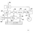
ここで図面の説明をすると、図面中の類似の参照符号は、複数の図面にわたって類似の構成要素を示しており、図1〜図7は、低エネルギー原子力熱電システム10を示し、低エネルギー原子力熱電システム10は、熱筐体30内の発熱器20、発熱器20に接続されたエネルギー変換システム40、エネルギー変換システム40に接続されたエネルギー貯蔵システム50、冷却システム60、及び、中央制御システム70を備える。発熱器20は、反応室22内でニッケル粉末23を水素と反応させて熱を発生させる。熱は、次に、エネルギー変換システム40に伝達されて、エネルギー貯蔵システム50での貯蔵のため電力に変換される。冷却システム60は、本発明の様々な構成要素に冷却をもたらし、制御システム70は、その全体的な動作を調節する。
Referring now to the drawings, wherein like reference numerals in the drawings indicate like components throughout the several views, FIGS. 1-7 illustrate a low energy nuclear
図1及び2は、本発明の全体的な構造及び動作を示すブロック図を示す。図1に示されるように、本発明は、内部液圧システム33により駆動される内部流体ループ32を有する発熱器20を備える。高温流体回路35は、熱を、発熱器20から、熱がエネルギーに変換されるエネルギー変換システム40に伝達し、冷却システム60を通してから、発熱器20に戻す。冷却回路66は、エネルギー変換システム40及び冷却システム60を通して、及び、任意選択的に乗り物16のA/Cシステム17を通して伝達する。冷却伝達回路67は、さらに、冷却システム60を離れた放熱器46に接続する。本発明は、発熱器20の低エネルギー原子力熱電発電を使用することにより、効率の良い持続可能な費用効果の高い方法で乗り物に給電するために使用されてもよい。
1 and 2 show block diagrams illustrating the overall structure and operation of the present invention. As shown in FIG. 1, the present invention includes a
B.発熱器 B. Heat generator
本発明は、エネルギー変換システム40内で変換されて、使用のためにエネルギー貯蔵システム50内に貯蔵される電力を生成するため、発熱器20を使用する。例示的な発熱器20が、図3に示されている。これが例示的な実施形態にすぎないことが理解され、従って、本発明では様々な他の実施形態を利用可能であることが理解される。従って、図に示されている例示的な発熱器20の構成が、本発明の範囲をそれに限定するものと解釈されるべきではない。
The present invention uses the
本発明では、様々な発熱器20が使用されてもよい。このような発熱器20の1つが、「ニッケルと水素の発熱反応を行う方法及び装置」に関する米国特許出願公開第2011/0005506号で開示されており、その公開内容は、参照により本明細書に援用される。他のこのような発熱器20が、「エネルギーを生成する方法及びそのための装置」に関する米国特許出願公開第2011/0249783号で開示されており、その公開内容は、参照により本明細書に援用される。
In the present invention,
図3に示すように、発熱器20は、概して、反応の主燃料として使用されるニッケル粉末23のような、ある量の反応物を収容する反応室22を備える。貯蔵された水素が水素注入器27を通して反応室22に注入され得るように水素貯蔵タンク24が提供される。反応を可能にして反応を制御するためニッケル粉末23に水素を圧入できるガス加圧器25が提供される。反応を開始して反応を制御するため、加熱器28と、マイクロ波発生器29などの無線周波発生器29とが、さらに提供される。
As shown in FIG. 3, the
発熱器20は、低エネルギー核反応を利用して、エネルギーを生成する際に使用するための熱を発生させる。水素ガスを使用した、ニッケル粉末23の非放射性同位体の変換反応に基づいて、熱が発生し、その結果、安定した銅同位体及び非放射性の銅同位体がもたらされる。従って、本発明は、何らかの放射性燃料の使用を必要とせず、放射性副産物を一切生成しない。
The
発熱器20は、好ましくは、図3に示すように、熱筐体30内に入れられている。高密度遮へい体31が、安全を図る目的で、発熱器20の様々な構成要素を囲う筐体30内に収容されている。シールド31は、好ましくは、変換により放射されるあらゆるガンマ線と、安全上の理由から使用されるあらゆる不活性ガスとを遮断することができる材料で構成されている。
The
発熱器20は、概して、反応室22を備える。反応室22は、ニッケル23の小粒子で構成された、ある量のニッケル粉末23を収容することに適応されている。水素貯蔵タンク24は、その中に弁26を有する注入器27を介して、反応室22に接続されている。水素貯蔵タンク24は、ボンベ内などの加圧された状態、または、水素化マグネシウムの形態などの固体状態のいずれかで水素ガスを貯蔵する。
The
ガス加圧器25は、弁26を使用することにより、注入器27を通して反応室22に注入される水素の圧力及び量を制御する。このような構成が、変換反応の開始及び量の調節を可能にし、これにより、室22内での反応により生成される熱エネルギーの量の制御を可能にする。
The
好ましくは電熱器28を備える加熱器28は、無線周波発生器29と組み合わせて使用されて、発熱器始動段階中に室22内の温度を上げることにより反応を開始させることと、その中で発生する熱量の調節を補助することとを行う。
A
特に発熱器20の様々な構成要素を制御するため、及び、その結果として、その全体的な動作を制御するため、制御装置37が提供される。制御装置37は、好ましくは、注入器27を通る水素入力流量を(例えば弁26の制御により)、及び、無線周波発生器29を制御するように適応される。さらに、制御装置37は、好ましくは、一体化された温度センサー38を使用して中心部21の温度を測定するように適応される。
In particular, a
発熱器20からの熱は、内部液圧システム33により動力供給される内部流体ループ32と、熱交換器34と、外部液圧システム36により動力供給される外部流体ループ35とを使用して、本発明のエネルギー変換システム40に伝達される。内部流体ループ32は、熱筐体30内に完全に封入された閉サイクル冷却剤流体ループを備える。反応室22内の熱反応による熱が、内部流体ループ32内の冷却流体に伝達されるように、内部流体ループ32が、反応室22の筐体を貫いている。
The heat from the
加熱された冷却流体は、図3に示すように筐体30内に位置する熱交換器34を通って、内部流体ループ32内で伝達される。熱交換器34は、高温流体回路35を備える外部流体ループ35に熱を伝達し、エネルギー変換システム40内での変換のために、その中の作動流体を加熱する。発熱器20のすべての動作が、閉サイクルで行われるので、自然界のバックグラウンド放射線と同じ程度の大きさのごくわずかのレベルのガンマ放射線の他には、どのような種類の放射物も生成されない。
The heated cooling fluid is transferred in the
いくつかの実施形態において、発熱器20及び後でさらに詳細に説明するエネルギー変換システム40は、単一の組立体に一体化されてもよく、この場合、発熱器20からの熱は、作動流体も冷却流体も一切必要とせずに、エネルギー変換システム40に直接伝達されることが理解される。
In some embodiments, the
C.エネルギー変換システム。 C. Energy conversion system.
本発明は、エネルギー変換システム40使用して、発熱器20で生成される熱をエネルギーに変換する。エネルギー変換システム40は、発熱器20で生成される熱を、エネルギー貯蔵システム50に貯蔵可能な電力に変換する、閉サイクルで作動する熱電変換器などの様々な構成要素を備えていてもよい。他の実施形態において、エネルギー変換システム40は、発熱器で生成される熱を、エネルギー貯蔵システム50に保存可能な回転運動に変換する、閉サイクルで作動する熱−運動変換器を備えていてもよい。
The present invention uses the
本発明のエネルギー変換システム40は、一般に、熱から直線運動を発生させるための少なくとも1のスターリングエンジン41と、スターリングエンジン41の直線運動により作動流体の圧力を上昇させる少なくとも1の単動ピストン圧縮器42又はブロワと、加圧された流体から回転運動を発生させるタービン48と、タービン48の回転から電力を発生させるロータリー発電機49とを備えることとなる。
The
図4に示すように、好ましい実施形態では、エネルギー変換システム40は、振動及びノイズを低減するように動的にバランスをとられて対置されて対として構成された第1のスターリングエンジン41aと第2のスターリングエンジン41bとを備える。スターリングエンジン41(a、b)は、外部液圧システム36により駆動される熱筐体30の外部流体ループ35から、加熱された作動流体を受け入れる。
As shown in FIG. 4, in the preferred embodiment, the
図4に示すように、第1の圧縮器42aは、第1のスターリングエンジン41aに接続されており、第2の圧縮器42bは、第2のスターリングエンジン41bに接続されている。圧縮器42は、好ましくは、それ自体がタービン48及びロータリー発電機49を含むタービン発電機47に接続されている単動ピストン圧縮器またはブロワを備える。
As shown in FIG. 4, the
高温流体回路35を介して伝達される発熱器20からの熱は、スターリングエンジン41のそれぞれに動力を供給して、両方のエンジンの膨張シリンダを高温に保ち、一方で、冷却流体が、低温液圧システム45を介してエンジン41に伝達されて、それぞれの圧縮シリンダを低温に保つ。
The heat from the
スターリングエンジン41は、本分野でよく知られており、使用において効率の良いことが知られている様々な構成のスターリングエンジン41が、本発明と共に使用されてもよい。好ましくは、それぞれのスターリングエンジン41は、従来の、ディスプレーサー型自由ピストンエンジン41を備え、ディスプレーサー型自由ピストンエンジン41において、パワーピストンは、単動ピストン圧縮器42を駆動する。スターリングエンジン41、圧縮器42及びタービン発電機47は、すべて、典型的にはヘリウムガスを含む同じ作動流体を使用する。液圧システム36、45は、動作の温度を調節及び制御し、その結果、エネルギー変換の効率を調節及び制御する。
The Stirling engine 41 is well known in the art, and various configurations of the Stirling engine 41 known to be efficient in use may be used with the present invention. Preferably, each Stirling engine 41 comprises a conventional displacer type free piston engine 41, in which the power piston drives a single acting piston compressor 42. Stirling engine 41, compressor 42 and
放熱器46は、外部液圧システム36に接続されて、残りの未使用の熱をすべて電動の乗り物の外に除去する。エネルギー変換システムのすべての動作は、閉サイクルで行われ、その結果、あらゆる種類のあらゆる放出物を防ぐ。
A
エネルギー変換システム40に関して、本発明者によってそれについての複数の代替実施形態がすでに考えられている。例えば、このような代替実施形態の一つにおいて、エネルギー変換システム40は、熱から直線運動を発生させる自由ピストンスターリングエンジン41と、スターリングエンジン41の直線運動から電力を発生させるリニア同期発電機とを備えていてもよい。
For the
他の実施形態において、エネルギー変換システム40は、閉サイクルで作動する熱−運動変換器を備え、発熱器20で生成される熱をエネルギー貯蔵システム50での貯蔵のための運動エネルギーに変換してもよい。運動エネルギーが、はずみ車エネルギー貯蔵システム50に貯蔵され得るように、このような構成は、通常、スターリングエンジン41、エンジン41の直線運動により作動流体の圧力を上昇させる単一の圧縮器42、及び、加圧された流体により回転運動を発生させるタービン48を備える。
In other embodiments, the
さらに別の他の実施形態において、エネルギー変換システム40は、作動流体からの熱を使用して液体の水を高圧蒸気に変える蒸発器を含む蒸気タービン発電機と、高圧蒸気から回転運動を発生させるタービン48と、タービンの回転により電力を発生させるロータリー発電機49と、タービン48から出た低圧チームを、冷却流体を使用して液体の水に変換して戻すことで蒸発器に戻ってサイクルを開始するための凝縮器とを備えていてもよい。代替的に、図8に示すように、作動流体としての超臨界二酸化炭素で、蒸気及び液体の水が置換されてもよい。
In yet another embodiment, the
他の代替実施形態において、エネルギー変換システム40は、例えば、一般に「Schoellサイクル」エンジンと呼ばれる、閉サイクルで作動する廃熱ランキンサイクル蒸気エンジンを備える熱電変換器を備えていてもよく、廃熱ランキンサイクル蒸気エンジンは、熱を、エネルギー貯蔵システム50に貯蔵され得る、または、電力に変換され得る回転運動に変換する。
In other alternative embodiments, the
他の代替実施形態は、加熱された伝達流体と冷却流体との間の温度差を電圧に変換する「ゼーベック」または「ペルティエ」効果を利用するサーモパイル組立体を備える熱電変換器を使用する。 Another alternative embodiment uses a thermoelectric converter with a thermopile assembly that utilizes a “Seebeck” or “Peltier” effect that converts the temperature difference between the heated transfer fluid and the cooling fluid into a voltage.
最後の代替実施形態は、近似エリクソンサイクルを使用して燃料セル内の水素の光分解及び再結合に依存する固体熱エンジンを備えるジョンソン熱電エネルギー変換器を使用し、それによって熱から電力を発生させる。 The last alternative embodiment uses a Johnson thermoelectric energy converter with a solid heat engine that relies on photolysis and recombination of hydrogen in the fuel cell using an approximate Ericsson cycle, thereby generating power from the heat .
D.エネルギー貯蔵システム D. Energy storage system
本発明は、エネルギー貯蔵システム50を使用して、エネルギー変換システム40により生成されるエネルギーを貯蔵する。本発明では、電池、はずみ車運動エネルギー貯蔵システム、またはその組み合わせを含む、様々な種類のエネルギー貯蔵システム50が使用されてもよい。
The present invention uses
好ましい実施形態では、エネルギー貯蔵システム50は、変換システム40により生成される電力を貯蔵するように適応された電池の組立体を備える。電池の動作温度は、発熱器20及び冷却システム60によりそれぞれ生成される、加熱された作動流体からの熱及び冷却流体からの冷たさを利用して、温度計で監視されてもよく、及び、電池温度システムで調節されてもよい。
In a preferred embodiment,
E.冷却システム E. Cooling system
図5は、本発明で使用される冷却システム60の例示的な実施形態を示す。冷却システム60は、好ましくは、エネルギー変換システム40の効率を高めるため、並びに、エネルギー貯蔵システム50、及び、場合によっては、乗り物の空調システムの温度の調節のための冷却源を提供するため、発熱器20の余剰な熱から有用な冷たさを発生させるのに使用される吸収式冷却装置を備える。
FIG. 5 illustrates an exemplary embodiment of a
冷却システム60は、概して、内部において低分圧環境中で冷媒流体が気化する蒸発器61を含み、その結果として、その周辺環境から熱を取り出す、及び冷却流体を冷却する。気体の冷媒流体は、吸収器62中の液体の吸収液中に吸収され、及び、溶解し、その結果、蒸発器61内でその分圧が下がり、より多くの液体の冷媒流体を気化させる。
The
液体の吸収液は、ポンプ63を介して熱交換ボイラー64に伝達されて、熱交換ボイラー64で液体の吸収液が加熱され、図5に示すように、溶解した冷媒流体を完全に気化させる。気化した流体は、次に、冷却水を使用する凝縮器65を通って凝縮して、蒸発器に液体の冷媒流体を再供給する。冷却システム60は、冷却回路66と冷却伝達回路67との両方を使用して、冷却システム60内に、及び冷却システム60から外に、流体、すなわち、熱及び冷たさを伝達する。
The liquid absorption liquid is transmitted to the
代替実施形態において、冷却システム60は、受動的または能動的な水−空気放熱器を備えていてもよい。能動的な実施形態において、冷却システム60の冷却性能を高めるため、電動送風機が使用されてもよい。
In alternative embodiments, the
他の代替実施形態において、冷却システム60は、冷却源として、電動の乗り物の外の利用可能な空気または水を使用した、熱交換器を元にした受動的または能動的なヒートシンクを備えていてもよい。
In other alternative embodiments, the
F.中央制御システム F. Central control system
本発明は、システム10全体の全体的な動作を調節するための中央冷却システム70を含む。制御システム70は、乗り物が走行しているとき、または、貯蔵システム50がその最大貯蔵容量未満であるとき、発熱器20を起動できる。制御システム70は、エネルギー貯蔵システム50がその最大貯蔵容量に達したとき、発熱器20を停止するようにも適応される。
The present invention includes a
制御システム70は、様々な実施形態を備えていてもよい。制御システム70は、発生する熱の量を調節するために発熱器20を起動/停止するコマンドを発熱器20の制御装置37に送信するように適応されることとなることが好ましい。さらに、液圧システム33、36、45を制御して、本発明全体の熱伝達及び冷却流体の流量を管理することとなるように適応される。
The
制御システム70は、エネルギー貯蔵システム50の温度調節システムなどの温度調節システムと連携して、需要に応じて電池の温度を上昇または低下させるように機能することにもなる。最後に、制御システム70は、乗り物の空調システムと連携して、乗り物内の気温を上昇または低下させることとなる。
The
G.乗り物 G. vehicle
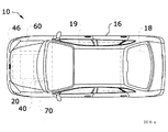
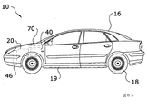
本発明は、例えば、バス、トラック、ボート、電車、飛行機、ヘリコプター、他の航空機などの様々な種類の乗り物16に使用されてもよい。本発明は、好ましくは、電気自動車16での使用に適応され、電気自動車16は、燃料補給毎に何千マイルかの長い移動距離を可能にする。乗り物16の重さは、所望の移動距離を達成するために必要な電池19の大きさ及び容量を小さくすることによって低減されてもよく、その結果として、乗り物の機動性及び相対的な性能を高めてもよい。図6a及び図6bは、自動車内で使用される本発明の例示的な実施形態を示す。図7は、航空機内で使用される本発明の例示的な実施形態を示す。
The present invention may be used for various types of
乗り物16は、その荷積み領域内に、発熱器20、エネルギー変換システム40、エネルギー貯蔵システム50、冷却システム60、及び、中央制御システム70を搭載するように設計されることとなる。本発明は、乗り物16の電動モーター18を駆動すること、及び、乗り物16の電池19に蓄えられるエネルギーを提供することに使用されてもよい。
The
本発明は、さらに、乗り物16の空調システム17の効率を高めること、及び/または、乗り物16の電池19の温度を調節することに使用されてもよい。発熱器20により生成される余剰な熱を別の冷却流体と組み合わせて使用することにより、乗り物16の電池19及び/または空調システム17の温度が、多くの場合は中央制御システム70と組み合わせて調節されてもよい。従って、電動の乗り物16の動作の顕著な欠点が、低減または完全に取り除かれ得る。
The present invention may also be used to increase the efficiency of the
H.代替実施形態の動作 H. Operation of alternative embodiments
図8は、閉鎖型ブレイトンサイクルとして作動する超臨界二酸化炭素タービン発電機80が本発明のエネルギー変換機能に使用される、本発明の代替実施形態を示す。ブレイトンサイクルは、熱エンジン及び閉サイクルガスタービンとの関連において使用される熱力学サイクルとして本分野でよく知られている。
FIG. 8 illustrates an alternative embodiment of the present invention in which a supercritical carbon
本発明の代替実施形態において、タービン発電機80は、高温流体回路35、88を介して本発明の発熱器20に熱的に接続され、高温流体回路35、88は、発熱器20からの熱を熱交換器34、87と連携してタービン発電機80に伝達してエネルギーに変換させる。
In an alternative embodiment of the present invention, the
様々な種類のタービン発電機80が使用されてもよい。好ましい実施形態が、図8に示されており、この好ましい実施形態は、すべてが同じ高温流体回路88を介して接続されたポンプ81、復熱装置82、タービン86及び凝縮器83を備え、高温流体回路88は、それ自体が、熱交換器87を介して本発明の発熱器20に熱的に接続されている。ポンプ81は、回路88に沿って超臨界流体を動かすように働く。
Various types of
復熱装置82は、流体が発熱器20を伴う熱交換器34、87に流れ込む前に、流体を予熱するのに使用される。復熱装置82は、さらに、流体が凝縮器83に流れ込む前に、流体を予冷し、凝縮器83は、冷却回路89を介して冷却水供給路及び冷却水帰路に接続される。
The
ギア85及び発電機84は、タービン86に接続されてエネルギーを生成し、そのエネルギーは、エネルギー貯蔵システム50に、電動モーター18に、電池19に、及び/または、発熱器20用の補助電力として、伝達される。
異なる定義がされていない限り、本明細書で用いられる技術用語及び科学用語は、すべて、この発明が属する技術分野の当業者によって通例理解されるのと同じ意味をもつ。本発明を実施または試験する時には、本明細書に記載の方法及び材料と同様または同等の方法及び材料が使用され得るが、適切な方法及び材料が前述のように説明されている。本明細書で言及したすべての刊行物、特許出願、特許、及び他の参照事項が、適用法令で認められる限りにおいて、全体として参照により援用される。矛盾する場合、定義を含め、本明細書が優先する。本発明は、その趣旨または本質的な性質から逸脱することなく、他の特定の形態で具現化されてもよく、従って、本実施形態が、すべての点において、例示であって、限定ではないとみなされることが望ましい。説明中の使用されるいずれの見出しも、単なる便宜上のものであり、法的効果も、限定する効果もない。 Unless defined differently, all technical and scientific terms used herein have the same meaning as commonly understood by one of ordinary skill in the art to which this invention belongs. Although methods and materials similar or equivalent to those described herein can be used in the practice or testing of the present invention, suitable methods and materials are described above. All publications, patent applications, patents, and other references mentioned herein are incorporated by reference in their entirety to the extent permitted by applicable law. In case of conflict, the present specification, including definitions, will control. The present invention may be embodied in other specific forms without departing from the spirit or essential characteristics thereof, and thus the embodiments are illustrative in all respects and not limiting. Should be considered. Any headings used in the description are for convenience only and have no legal or limiting effect.
表1:低エネルギー原子力熱電システムの構成要素の符号 Table 1: Signs of components of low energy nuclear thermoelectric system
10.低エネルギー原子力熱電
11.液体冷媒
12.冷却流体
13.
14.
15.電線管
16.乗り物
17.A/Cシステム
18.電動モーター
19.電池
10. Low energy nuclear thermoelectric 11. Liquid refrigerant 12. Cooling fluid 13.
14
15.
20.発熱器
21.反応室中心部
22.反応室
23.ニッケル粉末
24.水素貯蔵タンク
25.ガス加圧器
26.弁
27.水素注入器
28.加熱器
29.無線周波発生器
20.
30.熱筐体
31.高密度遮へい体
32.内部流体ループ
33.内部液圧システム
34.熱交換器
35.高温流体回路
36.外部液圧システム
37.制御装置
38.温度センサー
39.
30.
40.エネルギー変換システム
41.スターリングエンジン(a、b)
42.圧縮器(a、b)
43.
44.低温流体回路
45.低温液圧システム
46.放熱器
47.タービン発電機
48.タービン
49.ロータリー発電機
40. Energy conversion system 41. Stirling engine (a, b)
42. Compressor (a, b)
43.
44. Low
50.エネルギー貯蔵システム
51.
52.
53.
54.
55.
56.
57.
58.
59.
50. Energy storage system 51.
52.
53.
54.
55.
56.
57.
58.
59.
60.冷却システム
61.蒸発器
62.吸収器
63.ポンプ
64.ボイラー
65.凝縮器(Condensor)
66.冷却回路
67.冷却伝達
68.
69.
60.
66. Cooling
69.
70.中央制御システム
71.
72.
73.
74.
75.
76.
77.
78.
79.
70. Central control system 71.
72.
73.
74.
75.
76.
77.
78.
79.
80.CO2タービン発電機
81.ポンプ
82.復熱装置
83.凝縮器
84.発電機
85.ギア
86.タービン
87.熱交換器
88.高温流体回路
89.冷却回路
80.
Claims (21)
前記発熱器により生成される熱を電力に変換するように適応されたエネルギー変換システムと、
前記発熱器からの熱を前記エネルギー変換システムに伝達する高温流体回路と、
乗り物に給電する前記電力を貯蔵するエネルギー貯蔵システムと、
前記エネルギー変換システム及び前記エネルギー貯蔵システムを冷却する冷却システムと、
中央制御システムと、
を備える、乗り物用の低エネルギー原子力熱電システム。 A heat generator adapted to generate heat using low energy nuclear reactions;
An energy conversion system adapted to convert heat generated by the heater into electrical power;
A high-temperature fluid circuit for transferring heat from the heat generator to the energy conversion system;
An energy storage system for storing the power for powering the vehicle;
A cooling system for cooling the energy conversion system and the energy storage system;
A central control system,
A low energy nuclear thermoelectric system for vehicles, comprising:
前記発熱器により生成される熱を電力に変換するように適応されたエネルギー変換システムであって、前記エネルギー変換システムが、熱から直線運動を発生させる少なくとも1の熱エンジン、作動流体の圧力を上昇させる少なくとも1の圧縮器、タービン、及び、ロータリー発電機を備える、前記エネルギー変換システムと、
乗り物に給電する前記電力を貯蔵するエネルギー貯蔵システムと、
前記エネルギー変換システムと前記エネルギー貯蔵システムとを冷却する冷却システムと、
中央制御システムと、
を備える、乗り物用の低エネルギー原子力熱電システム。 A heat generator adapted to generate heat using low energy nuclear reactions;
An energy conversion system adapted to convert heat generated by the heat generator into electrical power, wherein the energy conversion system raises the pressure of the working fluid, at least one heat engine generating linear motion from the heat Said energy conversion system comprising at least one compressor, a turbine, and a rotary generator;
An energy storage system for storing the power for powering the vehicle;
A cooling system for cooling the energy conversion system and the energy storage system;
A central control system,
A low energy nuclear thermoelectric system for vehicles, comprising:
水素とのニッケル粉末の反応を利用して熱を発生させるように適応された発熱器であって、前記発熱器が、反応室と水素貯蔵タンクと前記反応室を前記水素貯蔵タンクに接続する水素注入器とを備え、前記発熱器が、前記水素貯蔵タンクと前記水素注入器との間に接続されたガス加圧器をさらに備え、前記発熱器が、加熱器と無線周波発生器とをさらに備え、前記発熱器が、熱筐体内に収容され、前記熱筐体が、高密度遮へい体を含み、前記発熱器が、前記発熱器内の熱を伝達する内部流体ループを含む、前記発熱器と、
中央制御システムと、
前記発熱器により生成される熱を電力に変換するように適応されたエネルギー変換システムであって、前記エネルギー変換システムが、熱から直線運動を発生させる第1のスターリングエンジン及び第2のスターリングエンジンと、作動流体の圧力を上昇させる第1の単動ピストン圧縮器及び第2の単動ピストン圧縮器と、タービン及びロータリー発電機とを備え、前記第1の単動ピストン圧縮器が、前記第1のスターリングエンジンに接続され、前記第2の単動ピストン圧縮器が、前記第2のスターリングエンジンに接続されている、前記エネルギー変換システムと、
前記発熱器からの熱を前記エネルギー変換システムに伝達する高温流体回路と、
前記乗り物に給電する前記電力を貯蔵するエネルギー貯蔵システムと、
前記エネルギー変換システム及び前記エネルギー貯蔵システムを冷却する冷却システムと、
前記エネルギー変換システムと前記冷却システムとの間に接続された冷却回路と、を備え、
前記発熱器が、前記空調システムに熱的に接続され、前記冷却回路が、前記空調システムに熱的に接続され、前記空調システムに高温の空気を提供するため、前記中央制御システムが、前記発熱器で生成される前記熱の少なくとも第1の部分の、前記空調システムへの直接の伝達に適応され、
前記発熱器が、前記1以上の電池に熱的に接続され、前記冷却回路が、前記1以上の電池に熱的に接続され、前記中央制御システムが、前記発熱器で生成される前記熱の少なくとも第2の部分と前記1以上の電池の温度を調節する前記冷却回路の冷却流体の少なくとも一部とを使用して前記1以上の電池の温度を調節するように適応される
乗り物用の低エネルギー原子力熱電システム。 A vehicle, wherein the vehicle includes one or more batteries, and the vehicle includes an air conditioning system;
A heat generator adapted to generate heat utilizing reaction of nickel powder with hydrogen, wherein the heat generator connects a reaction chamber, a hydrogen storage tank, and the reaction chamber to the hydrogen storage tank. An injector, wherein the heater further comprises a gas pressurizer connected between the hydrogen storage tank and the hydrogen injector, and the heater further comprises a heater and a radio frequency generator. The heater is housed in a thermal enclosure, the thermal enclosure includes a high density shield, and the heater includes an internal fluid loop for transferring heat in the heater; and ,
A central control system,
An energy conversion system adapted to convert heat generated by the heat generator into electrical power, wherein the energy conversion system generates a linear motion from the heat and a second Stirling engine; , A first single-acting piston compressor and a second single-acting piston compressor for increasing the pressure of the working fluid, a turbine and a rotary generator, wherein the first single-acting piston compressor is the first single-acting piston compressor. The energy conversion system connected to the second Stirling engine, wherein the second single-acting piston compressor is connected to the second Stirling engine;
A high-temperature fluid circuit for transferring heat from the heat generator to the energy conversion system;
An energy storage system for storing the power to supply the vehicle;
A cooling system for cooling the energy conversion system and the energy storage system;
A cooling circuit connected between the energy conversion system and the cooling system,
The central control system is configured to generate the heat because the heater is thermally connected to the air conditioning system and the cooling circuit is thermally connected to the air conditioning system to provide hot air to the air conditioning system. Adapted for direct transfer of at least a first part of the heat generated in a vessel to the air conditioning system;
The heat generator is thermally connected to the one or more batteries, the cooling circuit is thermally connected to the one or more batteries, and the central control system is configured to transmit the heat generated by the heat generator. Adapted to regulate the temperature of the one or more batteries using at least a second portion and at least a portion of the cooling fluid of the cooling circuit that regulates the temperature of the one or more batteries. Energy nuclear thermoelectric system.
A vehicle comprising the low energy nuclear thermoelectric system of any of claims 1-20.
Applications Claiming Priority (3)
| Application Number | Priority Date | Filing Date | Title |
|---|---|---|---|
| US13/848,888 US9540960B2 (en) | 2012-03-29 | 2013-03-22 | Low energy nuclear thermoelectric system |
| US13/848,888 | 2013-03-22 | ||
| PCT/EP2014/052961 WO2014146836A2 (en) | 2013-03-22 | 2014-02-14 | Low energy nuclear thermoelectric system |
Publications (2)
| Publication Number | Publication Date |
|---|---|
| JP2016521534A true JP2016521534A (en) | 2016-07-21 |
| JP2016521534A5 JP2016521534A5 (en) | 2017-06-01 |
Family
ID=50193447
Family Applications (1)
| Application Number | Title | Priority Date | Filing Date |
|---|---|---|---|
| JP2016503581A Pending JP2016521534A (en) | 2013-03-22 | 2014-02-14 | Low energy nuclear thermoelectric system |
Country Status (8)
| Country | Link |
|---|---|
| US (1) | US9540960B2 (en) |
| EP (1) | EP2976231A2 (en) |
| JP (1) | JP2016521534A (en) |
| KR (1) | KR102220025B1 (en) |
| CN (1) | CN105050848A (en) |
| CA (1) | CA2901506A1 (en) |
| RU (1) | RU2668383C2 (en) |
| WO (1) | WO2014146836A2 (en) |
Cited By (1)
| Publication number | Priority date | Publication date | Assignee | Title |
|---|---|---|---|---|
| JP2020527706A (en) * | 2017-07-13 | 2020-09-10 | エルイーエヌアール カーズ ソシエテ アノニムLenr Cars Sa | How to generate energy from dense hydrogen clusters |
Families Citing this family (21)
| Publication number | Priority date | Publication date | Assignee | Title |
|---|---|---|---|---|
| EP2476902B1 (en) * | 2011-01-13 | 2014-07-30 | Sincron S.r.l. | Method and assembly for converting solar radiation in mechanical power |
| DE102011122071B4 (en) * | 2011-12-22 | 2013-10-31 | Eads Deutschland Gmbh | Stirling engine with flapping wing for an emission-free aircraft |
| US10475980B2 (en) * | 2012-03-29 | 2019-11-12 | Lenr Cars Sa | Thermoelectric vehicle system |
| US9797309B2 (en) * | 2013-04-09 | 2017-10-24 | David J. Podrog | Hafnium turbine engine and method of operation |
| US20160079783A1 (en) * | 2014-09-11 | 2016-03-17 | Nissan North America, Inc. | Battery charging module for a vehicle |
| US10480084B1 (en) | 2016-03-03 | 2019-11-19 | Marathon Systems, Inc. | Modular cooling chamber for manifold of gaseous electrolysis apparatus with helium permeable element therefor |
| EP3401922A1 (en) * | 2017-05-12 | 2018-11-14 | RIToN Holding Ltd | Heating system |
| RU2749989C2 (en) * | 2017-07-21 | 2021-06-21 | Александр Прокопьевич Зиновьев | Rubber-tyred automobile for off-road transportation of people and goods |
| CN107785092A (en) * | 2017-11-01 | 2018-03-09 | 中国船舶重工集团公司第七〇九研究所 | The charger baby that can persistently use |
| US11318510B2 (en) | 2017-11-22 | 2022-05-03 | Gaiaca, LLC | Systems and methods for cannabis waste disposal |
| US10876061B2 (en) * | 2017-11-22 | 2020-12-29 | Gaiaca, LLC | Systems and methods for cannabis waste disposal |
| CN108983112B (en) * | 2018-04-27 | 2020-02-07 | 西安交通大学 | Small-size nuclear power supply integration test device |
| CN108988739B (en) * | 2018-08-22 | 2020-12-11 | 中国科学院合肥物质科学研究院 | Nuclear reactor combined wind power and solar photovoltaic grid-connected power generation system |
| CN109677639B (en) * | 2018-12-30 | 2020-08-04 | 上海空间推进研究所 | Space high-power nuclear power system based on closed Brayton cycle |
| US20210110938A1 (en) * | 2019-10-11 | 2021-04-15 | James F. Loan | Method and apparatus for controlling a low energy nuclear reaction |
| WO2021162822A2 (en) * | 2020-01-14 | 2021-08-19 | Quantum Industrial Development Corp. | Stirling powered unmanned aerial vehicle |
| EP4100971A1 (en) * | 2020-02-07 | 2022-12-14 | Ultra Safe Nuclear Corporation | Chargeable atomic battery and activation charging production methods |
| CN113320377B (en) * | 2021-06-29 | 2022-11-25 | 重庆金康赛力斯新能源汽车设计院有限公司 | Whole vehicle thermal management system capable of recycling energy and vehicle |
| CN113320378B (en) * | 2021-06-29 | 2022-08-09 | 重庆金康赛力斯新能源汽车设计院有限公司 | Efficient integrated engine thermal management system and vehicle |
| CN113539541A (en) * | 2021-07-19 | 2021-10-22 | 安徽中科超安科技有限公司 | Nuclear power generation power supply system and nuclear power automobile with same |
| US11846273B1 (en) * | 2022-08-17 | 2023-12-19 | Venus Aerospace Corp | Reactor rocket engine |
Citations (12)
| Publication number | Priority date | Publication date | Assignee | Title |
|---|---|---|---|---|
| JPH01294946A (en) * | 1988-05-20 | 1989-11-28 | Kubota Ltd | Waste heat utilizing device for engine |
| JPH032689A (en) * | 1989-05-31 | 1991-01-09 | Hitachi Ltd | Low-temperature nuclear fusion energy system |
| JPH05256994A (en) * | 1992-03-13 | 1993-10-08 | Mitsubishi Heavy Ind Ltd | Nuclear power generator |
| JPH07279758A (en) * | 1994-04-13 | 1995-10-27 | Daikin Ind Ltd | Co-generation device |
| JP2001130268A (en) * | 1999-11-09 | 2001-05-15 | Denso Corp | Forced cooling device of battery for electric car |
| JP2007522438A (en) * | 2003-11-21 | 2007-08-09 | グローバル テクノロジーズ,インコーポレイテッド | Nuclear battery |
| JP2007291869A (en) * | 2006-04-21 | 2007-11-08 | Japan Atomic Energy Agency | Combined brayton cycle power generation system device using nuclear heat |
| JP2010208449A (en) * | 2009-03-10 | 2010-09-24 | Toshihisa Shirakawa | Nuclear ship corresponding to fuel-filled jet plane crash |
| US20110005506A1 (en) * | 2008-04-09 | 2011-01-13 | Andrea Rossi | Method and apparatus for carrying out nickel and hydrogen exothermal reaction |
| JP2011116234A (en) * | 2009-12-03 | 2011-06-16 | Toyota Industries Corp | Air-conditioning system for moving body |
| JP2012510050A (en) * | 2008-11-24 | 2012-04-26 | ピアンテリ,シルビア | Method and apparatus for producing energy |
| JP2012230069A (en) * | 2011-04-27 | 2012-11-22 | Hitachi-Ge Nuclear Energy Ltd | Auxiliary power supply of nuclear installation |
Family Cites Families (80)
| Publication number | Priority date | Publication date | Assignee | Title |
|---|---|---|---|---|
| US4072186A (en) | 1976-04-05 | 1978-02-07 | Ford Motor Company | Dual function heater core |
| DE3434532C1 (en) | 1984-09-20 | 1986-02-13 | Messerschmitt-Bölkow-Blohm GmbH, 8012 Ottobrunn | Power supply system for a motor vehicle |
| RU2115178C1 (en) | 1989-03-13 | 1998-07-10 | Юниверсити Оф Юта Рисерч Фаундейшн | Heat generation process and device |
| BE1002780A7 (en) | 1989-04-21 | 1991-06-04 | Den Bogaert Joannes Van | Nuclear fusion |
| JPH02310494A (en) | 1989-05-26 | 1990-12-26 | Matsushita Electric Ind Co Ltd | Low-temperature nuclear fusion device |
| BE1002781A6 (en) | 1989-06-05 | 1991-06-04 | Van Den Bogaert Joannes | Method for the production of energy by means of nuclear fusion |
| EP0568118B1 (en) | 1989-08-04 | 1997-02-12 | Canon Kabushiki Kaisha | Process for storing hydrogen, apparatus and method for generating heat energy, using the process |
| BE1003296A6 (en) | 1990-01-10 | 1992-02-18 | Van Den Bogaert Joannes | Nuclear fusion |
| JP2773417B2 (en) | 1990-09-28 | 1998-07-09 | アイシン精機株式会社 | Free piston stirling engine |
| US5172784A (en) | 1991-04-19 | 1992-12-22 | Varela Jr Arthur A | Hybrid electric propulsion system |
| JPH0675072A (en) | 1991-06-24 | 1994-03-18 | Aisin Aw Co Ltd | P/f effect device |
| WO1993000683A1 (en) | 1991-06-27 | 1993-01-07 | Electric Power Research Institute, Inc. | Apparatus for producing heat from deuterated film-coated palladium |
| DE4129330A1 (en) | 1991-07-12 | 1993-01-14 | Campobasso Andreas P | Hydrogen@ prodn. in vehicle using stirling engine - to convert IC engine waste heat into electrical energy for water electrolyser |
| DE4132939A1 (en) | 1991-10-04 | 1993-04-08 | Bayerische Motoren Werke Ag | Air-conditioning unit for electric vehicle passenger space - uses stirling heat pump with reversible drive allowing cooling or heating operations |
| WO1993017437A1 (en) | 1992-02-24 | 1993-09-02 | Bush Robert T | Method and apparatus for alkali-hydrogen fusion power generation |
| JPH0618683A (en) | 1992-07-03 | 1994-01-28 | Doke Masaaki | Cylinder plating type vibrating electrode apparatus for normal temperature nuclear fusion |
| JPH06137699A (en) | 1992-10-27 | 1994-05-20 | Toyota Autom Loom Works Ltd | Air conditioner for vehicle |
| WO1994028197A2 (en) | 1993-05-25 | 1994-12-08 | Eneco, Inc. | Hydrogen activated heat generation apparatus |
| IT1282858B1 (en) | 1994-01-27 | 1998-04-01 | Francesco Piantelli | THERMOFUSER ENERGY GENERATOR WITH FASEC EFFECT: ANARMONIC FUSION STIMULATED WITH HEAT EMISSION. |
| DE19732307A1 (en) | 1996-08-22 | 1998-02-26 | Volkswagen Ag | Auxiliary drive system for road vehicle |
| US5775273A (en) * | 1997-07-01 | 1998-07-07 | Sunpower, Inc. | Free piston internal combustion engine |
| US7469760B2 (en) | 2000-03-02 | 2008-12-30 | Deka Products Limited Partnership | Hybrid electric vehicles using a stirling engine |
| DE10013080A1 (en) | 2000-03-17 | 2001-09-20 | Still Gmbh | Drive system for mobile electrically driven machine, especially industrial truck, has drive machine designed as Stirling engine, traction battery provided and electrical drive motor(s) supplied by generator and/or traction battery |
| US6543229B2 (en) | 2000-06-14 | 2003-04-08 | Stm Power, Inc. | Exhaust gas alternator system |
| WO2002029826A1 (en) * | 2000-10-03 | 2002-04-11 | Cheng Sing Wang | COLD FUSION WITH A PILOT FOR SELF GENERATING NEUTRON AND β-PARTICLE |
| BR0107399A (en) * | 2000-10-30 | 2002-10-22 | Questair Technologies Inc | Energy efficient gas separation for fuel cells |
| DE10054022A1 (en) | 2000-11-01 | 2002-05-08 | Bayerische Motoren Werke Ag | Method for operating a heat engine |
| RU2195717C1 (en) * | 2001-08-23 | 2002-12-27 | Киркинский Виталий Алексеевич | Energy generating device |
| DE10243178B4 (en) | 2002-09-18 | 2004-08-05 | Daimlerchrysler Ag | Device for supplying an air conditioning unit and electrical consumers in a vehicle with energy |
| JPWO2004034406A1 (en) | 2002-10-11 | 2006-03-02 | プラズマ技研工業株式会社 | Hydrogen condensate and heat generation method using the same |
| JP4248303B2 (en) | 2003-05-09 | 2009-04-02 | 本田技研工業株式会社 | Power unit comprising a combustion engine and a Stirling engine |
| WO2005017918A2 (en) | 2003-08-12 | 2005-02-24 | Energetics Technologies, L.L.C. | Pulsed low energy nuclear reaction power generators |
| FR2874975B1 (en) * | 2004-09-07 | 2008-12-26 | Philippe Marc Montesinos | PRODUCTION OF LOW ENERGY SOLAR ELECTRICITY |
| US7798204B2 (en) | 2004-09-14 | 2010-09-21 | Cyclone Power Technologies, Inc. | Centrifugal condenser |
| US20070256415A1 (en) | 2004-09-14 | 2007-11-08 | Cyclone Technologies, Lllp | Clearance volume valves in a heat regenerative engine |
| US7856823B2 (en) | 2004-09-14 | 2010-12-28 | Cyclone Power Technologies, Inc. | Pre-heater coil in a heat regenerative engine |
| US20070261681A1 (en) | 2004-09-14 | 2007-11-15 | Cyclone Technologies, Lllp | Engine shrouding with air to air heat exchanger |
| US7730873B2 (en) | 2004-09-14 | 2010-06-08 | Cyclone Power Technologies, Inc. | Valve controlled throttle mechanism in a heat regenerative engine |
| US7784280B2 (en) | 2004-09-14 | 2010-08-31 | Cyclone Power Technologies, Inc. | Engine reversing and timing control mechanism in a heat regenerative engine |
| US7080512B2 (en) | 2004-09-14 | 2006-07-25 | Cyclone Technologies Lllp | Heat regenerative engine |
| EP1836378A4 (en) * | 2004-12-24 | 2010-05-26 | Renewable Energy Systems Ltd | Methods and apparatus for power generation |
| CN101563182B (en) | 2005-09-07 | 2012-08-15 | 普拉提奥股份公司 | Method for producing thermal energy |
| US7893414B2 (en) | 2005-09-09 | 2011-02-22 | Lattice Energy Llc | Apparatus and method for absorption of incident gamma radiation and its conversion to outgoing radiation at less penetrating, lower energies and frequencies |
| US7407382B2 (en) | 2005-09-13 | 2008-08-05 | Cyclone Power Technologies, Inc. | Steam generator in a heat regenerative engine |
| US20070056287A1 (en) | 2005-09-13 | 2007-03-15 | Cyclone Technologies Lllp | Splitter valve in a heat regenerative engine |
| CN101395677B (en) | 2005-12-29 | 2012-07-04 | 布里渊散射能量公司 | Energy generation apparatus and method |
| ES2299348B1 (en) * | 2006-05-11 | 2009-02-01 | Alset Technology Llc | CONTROLLED NUCLEAR FUSION PROCESS. |
| US20070268045A1 (en) | 2006-05-22 | 2007-11-22 | Profusion Energy, Inc. | Drive Circuit And Method For Semiconductor Devices |
| US8624636B2 (en) | 2006-05-22 | 2014-01-07 | Brillouin Energy Corp. | Drive circuit and method for semiconductor devices |
| US20080047272A1 (en) | 2006-08-28 | 2008-02-28 | Harry Schoell | Heat regenerative mini-turbine generator |
| CN101187329A (en) * | 2006-11-17 | 2008-05-28 | 林耀章 | Device for producing new energy using internal combustion engine waste heat energy conversion |
| US8419919B1 (en) | 2007-03-14 | 2013-04-16 | Jwk International Corporation | System and method for generating particles |
| US8603405B2 (en) | 2007-03-29 | 2013-12-10 | Npl Associates, Inc. | Power units based on dislocation site techniques |
| US8440165B2 (en) | 2007-03-29 | 2013-05-14 | Npl Associates, Inc. | Dislocation site density techniques |
| US8526560B2 (en) | 2007-03-29 | 2013-09-03 | Npl Associates, Inc. | Method of using deuterium-cluster foils for an intense pulsed neutron source |
| US8227020B1 (en) | 2007-03-29 | 2012-07-24 | Npl Associates, Inc. | Dislocation site formation techniques |
| US20090090573A1 (en) * | 2007-10-03 | 2009-04-09 | Boone Daniel J | Hybrid electric vehicle and towable trailer that uses renewable solid fuel |
| US8191663B2 (en) | 2007-12-07 | 2012-06-05 | Boncodin Franz B | Radioisotope powered engineless vehicle |
| DE102008007159A1 (en) | 2008-02-01 | 2009-07-09 | Daimler Ag | Drive unit i.e. hybrid drive, for vehicle i.e. road vehicle, has stirling engine and generator forming integral stirling unit with generator section in which kinetic energy is converted into electricity |
| US20090277152A1 (en) * | 2008-05-07 | 2009-11-12 | Ronald Steven Sutherland | Quasi-isobaric heat engine |
| US20090283007A1 (en) * | 2008-05-14 | 2009-11-19 | William Gregory Taylor | Nuclear locomotive |
| WO2010033927A1 (en) | 2008-09-22 | 2010-03-25 | Richard Westfall | Radioisotope thermal generator |
| US7992386B2 (en) | 2008-11-03 | 2011-08-09 | Cyclone Power Technologies, Inc. | Waste heat engine |
| DE102009005852A1 (en) * | 2009-01-23 | 2010-07-29 | Li-Tec Battery Gmbh | Temperate battery system |
| DE102009007231A1 (en) * | 2009-02-03 | 2010-08-12 | Siemens Aktiengesellschaft | Vehicle, in particular motor vehicle |
| WO2010104601A1 (en) * | 2009-03-12 | 2010-09-16 | Seale Joseph B | Heat engine with regenerator and timed gas exchange |
| US20100283262A1 (en) * | 2009-05-11 | 2010-11-11 | Caterpillar Inc. | Energy Recovery And Cooling System For A Hybrid Machine |
| US8508057B2 (en) | 2009-08-03 | 2013-08-13 | David J. Schulte | Power generator |
| CA2767683A1 (en) * | 2009-08-07 | 2011-02-10 | Blacklight Power, Inc. | Heterogeneous hydrogen-catalyst power system |
| US8096128B2 (en) * | 2009-09-17 | 2012-01-17 | Echogen Power Systems | Heat engine and heat to electricity systems and methods |
| US8303865B1 (en) | 2009-12-15 | 2012-11-06 | Brown-Cravens-Taylor | Enhanced alpha particle emitter |
| CA2791472A1 (en) * | 2010-03-10 | 2011-09-15 | Bhp Billiton Aluminium Technologies Limited | Heat recovery system for pyrometallurgical vessel using thermoelectric/thermomagnetic devices |
| US20120159951A1 (en) * | 2010-12-24 | 2012-06-28 | Avery Maurice C | Vehicle Propulsion System |
| TWI468629B (en) * | 2010-12-30 | 2015-01-11 | Joy Ride Technology Co Ltd | Air Energy Energy Saving Air Conditioning Power Generation System |
| ITPI20110046A1 (en) | 2011-04-26 | 2012-10-27 | Chellini Fabio | METHOD AND SYSTEM TO GENERATE ENERGY BY MEANS OF NUCLEAR REACTIONS OF HYDROGEN ADSORBED BY ORBITAL CATCH FROM A CRYSTALLINE NANOSTRUCTURE OF A METAL |
| US9115913B1 (en) | 2012-03-14 | 2015-08-25 | Leonardo Corporation | Fluid heater |
| US20150110237A1 (en) * | 2012-05-11 | 2015-04-23 | Borealis Technical Limited | Method and System for High Efficiency Electricity Generation Using Low Energy Thermal Heat Generation and Thermionic Devices |
| US20140326711A1 (en) | 2013-05-02 | 2014-11-06 | Leonardo Corporation | Devices and methods for heat generation |
| US9181866B2 (en) * | 2013-06-21 | 2015-11-10 | Caterpillar Inc. | Energy recovery and cooling system for hybrid machine powertrain |
| TW201615328A (en) | 2014-10-21 | 2016-05-01 | Sportsman Corp | Holding clamp |
-
2013
- 2013-03-22 US US13/848,888 patent/US9540960B2/en active Active
-
2014
- 2014-02-14 CA CA2901506A patent/CA2901506A1/en not_active Abandoned
- 2014-02-14 KR KR1020157029434A patent/KR102220025B1/en active IP Right Grant
- 2014-02-14 JP JP2016503581A patent/JP2016521534A/en active Pending
- 2014-02-14 EP EP14707669.9A patent/EP2976231A2/en not_active Ceased
- 2014-02-14 WO PCT/EP2014/052961 patent/WO2014146836A2/en active Application Filing
- 2014-02-14 RU RU2015131057A patent/RU2668383C2/en active
- 2014-02-14 CN CN201480017039.2A patent/CN105050848A/en active Pending
Patent Citations (12)
| Publication number | Priority date | Publication date | Assignee | Title |
|---|---|---|---|---|
| JPH01294946A (en) * | 1988-05-20 | 1989-11-28 | Kubota Ltd | Waste heat utilizing device for engine |
| JPH032689A (en) * | 1989-05-31 | 1991-01-09 | Hitachi Ltd | Low-temperature nuclear fusion energy system |
| JPH05256994A (en) * | 1992-03-13 | 1993-10-08 | Mitsubishi Heavy Ind Ltd | Nuclear power generator |
| JPH07279758A (en) * | 1994-04-13 | 1995-10-27 | Daikin Ind Ltd | Co-generation device |
| JP2001130268A (en) * | 1999-11-09 | 2001-05-15 | Denso Corp | Forced cooling device of battery for electric car |
| JP2007522438A (en) * | 2003-11-21 | 2007-08-09 | グローバル テクノロジーズ,インコーポレイテッド | Nuclear battery |
| JP2007291869A (en) * | 2006-04-21 | 2007-11-08 | Japan Atomic Energy Agency | Combined brayton cycle power generation system device using nuclear heat |
| US20110005506A1 (en) * | 2008-04-09 | 2011-01-13 | Andrea Rossi | Method and apparatus for carrying out nickel and hydrogen exothermal reaction |
| JP2012510050A (en) * | 2008-11-24 | 2012-04-26 | ピアンテリ,シルビア | Method and apparatus for producing energy |
| JP2010208449A (en) * | 2009-03-10 | 2010-09-24 | Toshihisa Shirakawa | Nuclear ship corresponding to fuel-filled jet plane crash |
| JP2011116234A (en) * | 2009-12-03 | 2011-06-16 | Toyota Industries Corp | Air-conditioning system for moving body |
| JP2012230069A (en) * | 2011-04-27 | 2012-11-22 | Hitachi-Ge Nuclear Energy Ltd | Auxiliary power supply of nuclear installation |
Non-Patent Citations (1)
| Title |
|---|
| NICOLAS CHAUVIN: "LENR Powered Electric Vehicles", ILENRS, JPN7018003728, 3 July 2012 (2012-07-03), US, ISSN: 0004048613 * |
Cited By (1)
| Publication number | Priority date | Publication date | Assignee | Title |
|---|---|---|---|---|
| JP2020527706A (en) * | 2017-07-13 | 2020-09-10 | エルイーエヌアール カーズ ソシエテ アノニムLenr Cars Sa | How to generate energy from dense hydrogen clusters |
Also Published As
| Publication number | Publication date |
|---|---|
| RU2015131057A (en) | 2017-04-28 |
| CN105050848A (en) | 2015-11-11 |
| WO2014146836A3 (en) | 2015-03-26 |
| WO2014146836A2 (en) | 2014-09-25 |
| KR102220025B1 (en) | 2021-02-25 |
| BR112015023919A2 (en) | 2017-07-18 |
| US20130263597A1 (en) | 2013-10-10 |
| US9540960B2 (en) | 2017-01-10 |
| CA2901506A1 (en) | 2014-09-25 |
| KR20150135362A (en) | 2015-12-02 |
| EP2976231A2 (en) | 2016-01-27 |
| RU2668383C2 (en) | 2018-09-28 |
Similar Documents
| Publication | Publication Date | Title |
|---|---|---|
| JP2016521534A (en) | Low energy nuclear thermoelectric system | |
| US8616323B1 (en) | Hybrid power systems | |
| JP2016521534A5 (en) | ||
| US10475980B2 (en) | Thermoelectric vehicle system | |
| CN101576024B (en) | Heat returning closed cooling recirculation system of Brighton scramjet | |
| CN112880451A (en) | CO based on supplemental external energy2Gas-liquid phase change energy storage device and method | |
| CN104884874A (en) | Coupled chemical-thermal solar power system and method | |
| JP2014088868A (en) | Multifunctional solar energy cogeneration system | |
| CN109612132A (en) | A kind of self-loopa heat management and electricity generation system for lunar base | |
| US10294891B2 (en) | Energy collector system applicable to combustion engines | |
| CN104992730A (en) | Molten-salt nuclear reactor and airborne power system based on same | |
| CN104392750B (en) | Low temperature nuclear reactor and the onboard power systems based on low temperature nuclear reactor | |
| CN110359973B (en) | Compressor complementary energy recovery system | |
| CN109944757A (en) | A kind of solar heat power generation system and working method applied in the space environment | |
| JP2014005776A (en) | Air conditioning power generation system | |
| US20120153874A1 (en) | Assembly and method for supplying energy to motorised vehicles | |
| JP2003184650A (en) | External combustion engine driven by heat pump | |
| JP2015034544A (en) | Energy system using external combustion engine | |
| CN209212324U (en) | A kind of compact reactor system applied to space environment | |
| BR112015023919B1 (en) | ELECTRIC CAR, LOW ENERGY NUCLEAR THERMAL SYSTEM AND VEHICLE | |
| KR20100092832A (en) | A cogeneration equipment using solar energy | |
| CN209212477U (en) | A kind of solar heat power generation system applied in the space environment | |
| CN114439558B (en) | Hybrid-working-medium-based supercritical recompression Brayton-Rankine cycle nuclear power system | |
| CN203218896U (en) | Novel air energy charging station | |
| Franke et al. | Assessment of metal hydride reactors as thermal management enhancement of hydrogen fuel cells in electric aircraft |
Legal Events
| Date | Code | Title | Description |
|---|---|---|---|
| A621 | Written request for application examination |
Free format text: JAPANESE INTERMEDIATE CODE: A621 Effective date: 20170127 |
|
| RD13 | Notification of appointment of power of sub attorney |
Free format text: JAPANESE INTERMEDIATE CODE: A7433 Effective date: 20170130 |
|
| A521 | Request for written amendment filed |
Free format text: JAPANESE INTERMEDIATE CODE: A821 Effective date: 20170130 |
|
| A521 | Request for written amendment filed |
Free format text: JAPANESE INTERMEDIATE CODE: A523 Effective date: 20170411 |
|
| A131 | Notification of reasons for refusal |
Free format text: JAPANESE INTERMEDIATE CODE: A131 Effective date: 20171212 |
|
| A601 | Written request for extension of time |
Free format text: JAPANESE INTERMEDIATE CODE: A601 Effective date: 20180306 |
|
| A521 | Request for written amendment filed |
Free format text: JAPANESE INTERMEDIATE CODE: A523 Effective date: 20180501 |
|
| A131 | Notification of reasons for refusal |
Free format text: JAPANESE INTERMEDIATE CODE: A131 Effective date: 20181106 |
|
| A601 | Written request for extension of time |
Free format text: JAPANESE INTERMEDIATE CODE: A601 Effective date: 20190130 |
|
| A02 | Decision of refusal |
Free format text: JAPANESE INTERMEDIATE CODE: A02 Effective date: 20190604 |