JP2016515005A - Tissue capture bone anchor - Google Patents
Tissue capture bone anchor Download PDFInfo
- Publication number
- JP2016515005A JP2016515005A JP2016500846A JP2016500846A JP2016515005A JP 2016515005 A JP2016515005 A JP 2016515005A JP 2016500846 A JP2016500846 A JP 2016500846A JP 2016500846 A JP2016500846 A JP 2016500846A JP 2016515005 A JP2016515005 A JP 2016515005A
- Authority
- JP
- Japan
- Prior art keywords
- anchor
- expander
- suture
- bone
- rim
- Prior art date
- Legal status (The legal status is an assumption and is not a legal conclusion. Google has not performed a legal analysis and makes no representation as to the accuracy of the status listed.)
- Pending
Links
Images


Classifications
-
- A—HUMAN NECESSITIES
- A61—MEDICAL OR VETERINARY SCIENCE; HYGIENE
- A61B—DIAGNOSIS; SURGERY; IDENTIFICATION
- A61B17/00—Surgical instruments, devices or methods, e.g. tourniquets
- A61B17/04—Surgical instruments, devices or methods, e.g. tourniquets for suturing wounds; Holders or packages for needles or suture materials
-
- A—HUMAN NECESSITIES
- A61—MEDICAL OR VETERINARY SCIENCE; HYGIENE
- A61F—FILTERS IMPLANTABLE INTO BLOOD VESSELS; PROSTHESES; DEVICES PROVIDING PATENCY TO, OR PREVENTING COLLAPSING OF, TUBULAR STRUCTURES OF THE BODY, e.g. STENTS; ORTHOPAEDIC, NURSING OR CONTRACEPTIVE DEVICES; FOMENTATION; TREATMENT OR PROTECTION OF EYES OR EARS; BANDAGES, DRESSINGS OR ABSORBENT PADS; FIRST-AID KITS
- A61F2/00—Filters implantable into blood vessels; Prostheses, i.e. artificial substitutes or replacements for parts of the body; Appliances for connecting them with the body; Devices providing patency to, or preventing collapsing of, tubular structures of the body, e.g. stents
- A61F2/02—Prostheses implantable into the body
- A61F2/08—Muscles; Tendons; Ligaments
- A61F2/0811—Fixation devices for tendons or ligaments
-
- A—HUMAN NECESSITIES
- A61—MEDICAL OR VETERINARY SCIENCE; HYGIENE
- A61B—DIAGNOSIS; SURGERY; IDENTIFICATION
- A61B17/00—Surgical instruments, devices or methods, e.g. tourniquets
- A61B17/04—Surgical instruments, devices or methods, e.g. tourniquets for suturing wounds; Holders or packages for needles or suture materials
- A61B17/0401—Suture anchors, buttons or pledgets, i.e. means for attaching sutures to bone, cartilage or soft tissue; Instruments for applying or removing suture anchors
-
- A—HUMAN NECESSITIES
- A61—MEDICAL OR VETERINARY SCIENCE; HYGIENE
- A61B—DIAGNOSIS; SURGERY; IDENTIFICATION
- A61B17/00—Surgical instruments, devices or methods, e.g. tourniquets
- A61B17/04—Surgical instruments, devices or methods, e.g. tourniquets for suturing wounds; Holders or packages for needles or suture materials
- A61B17/0485—Devices or means, e.g. loops, for capturing the suture thread and threading it through an opening of a suturing instrument or needle eyelet
-
- A—HUMAN NECESSITIES
- A61—MEDICAL OR VETERINARY SCIENCE; HYGIENE
- A61B—DIAGNOSIS; SURGERY; IDENTIFICATION
- A61B17/00—Surgical instruments, devices or methods, e.g. tourniquets
- A61B17/04—Surgical instruments, devices or methods, e.g. tourniquets for suturing wounds; Holders or packages for needles or suture materials
- A61B17/0483—Hand-held instruments for holding sutures
-
- A—HUMAN NECESSITIES
- A61—MEDICAL OR VETERINARY SCIENCE; HYGIENE
- A61B—DIAGNOSIS; SURGERY; IDENTIFICATION
- A61B17/00—Surgical instruments, devices or methods, e.g. tourniquets
- A61B17/04—Surgical instruments, devices or methods, e.g. tourniquets for suturing wounds; Holders or packages for needles or suture materials
- A61B17/0401—Suture anchors, buttons or pledgets, i.e. means for attaching sutures to bone, cartilage or soft tissue; Instruments for applying or removing suture anchors
- A61B2017/0409—Instruments for applying suture anchors
-
- A—HUMAN NECESSITIES
- A61—MEDICAL OR VETERINARY SCIENCE; HYGIENE
- A61B—DIAGNOSIS; SURGERY; IDENTIFICATION
- A61B17/00—Surgical instruments, devices or methods, e.g. tourniquets
- A61B17/04—Surgical instruments, devices or methods, e.g. tourniquets for suturing wounds; Holders or packages for needles or suture materials
- A61B17/0401—Suture anchors, buttons or pledgets, i.e. means for attaching sutures to bone, cartilage or soft tissue; Instruments for applying or removing suture anchors
- A61B2017/0414—Suture anchors, buttons or pledgets, i.e. means for attaching sutures to bone, cartilage or soft tissue; Instruments for applying or removing suture anchors having a suture-receiving opening, e.g. lateral opening
-
- A—HUMAN NECESSITIES
- A61—MEDICAL OR VETERINARY SCIENCE; HYGIENE
- A61B—DIAGNOSIS; SURGERY; IDENTIFICATION
- A61B17/00—Surgical instruments, devices or methods, e.g. tourniquets
- A61B17/04—Surgical instruments, devices or methods, e.g. tourniquets for suturing wounds; Holders or packages for needles or suture materials
- A61B17/0401—Suture anchors, buttons or pledgets, i.e. means for attaching sutures to bone, cartilage or soft tissue; Instruments for applying or removing suture anchors
- A61B2017/0427—Suture anchors, buttons or pledgets, i.e. means for attaching sutures to bone, cartilage or soft tissue; Instruments for applying or removing suture anchors having anchoring barbs or pins extending outwardly from the anchor body
- A61B2017/0429—Suture anchors, buttons or pledgets, i.e. means for attaching sutures to bone, cartilage or soft tissue; Instruments for applying or removing suture anchors having anchoring barbs or pins extending outwardly from the anchor body the barbs being expanded by a mechanical mechanism which also locks them in the expanded state
- A61B2017/043—Suture anchors, buttons or pledgets, i.e. means for attaching sutures to bone, cartilage or soft tissue; Instruments for applying or removing suture anchors having anchoring barbs or pins extending outwardly from the anchor body the barbs being expanded by a mechanical mechanism which also locks them in the expanded state by insertion of a separate spreading member into the anchor
- A61B2017/0432—Suture anchors, buttons or pledgets, i.e. means for attaching sutures to bone, cartilage or soft tissue; Instruments for applying or removing suture anchors having anchoring barbs or pins extending outwardly from the anchor body the barbs being expanded by a mechanical mechanism which also locks them in the expanded state by insertion of a separate spreading member into the anchor the separate member staying in the anchor after placement
-
- A—HUMAN NECESSITIES
- A61—MEDICAL OR VETERINARY SCIENCE; HYGIENE
- A61B—DIAGNOSIS; SURGERY; IDENTIFICATION
- A61B17/00—Surgical instruments, devices or methods, e.g. tourniquets
- A61B17/04—Surgical instruments, devices or methods, e.g. tourniquets for suturing wounds; Holders or packages for needles or suture materials
- A61B17/0401—Suture anchors, buttons or pledgets, i.e. means for attaching sutures to bone, cartilage or soft tissue; Instruments for applying or removing suture anchors
- A61B2017/0438—Suture anchors, buttons or pledgets, i.e. means for attaching sutures to bone, cartilage or soft tissue; Instruments for applying or removing suture anchors slotted, i.e. having a longitudinal slot for enhancing their elasticity
-
- A—HUMAN NECESSITIES
- A61—MEDICAL OR VETERINARY SCIENCE; HYGIENE
- A61B—DIAGNOSIS; SURGERY; IDENTIFICATION
- A61B17/00—Surgical instruments, devices or methods, e.g. tourniquets
- A61B17/04—Surgical instruments, devices or methods, e.g. tourniquets for suturing wounds; Holders or packages for needles or suture materials
- A61B17/0401—Suture anchors, buttons or pledgets, i.e. means for attaching sutures to bone, cartilage or soft tissue; Instruments for applying or removing suture anchors
- A61B2017/0445—Suture anchors, buttons or pledgets, i.e. means for attaching sutures to bone, cartilage or soft tissue; Instruments for applying or removing suture anchors cannulated, e.g. with a longitudinal through-hole for passage of an instrument
-
- A—HUMAN NECESSITIES
- A61—MEDICAL OR VETERINARY SCIENCE; HYGIENE
- A61B—DIAGNOSIS; SURGERY; IDENTIFICATION
- A61B17/00—Surgical instruments, devices or methods, e.g. tourniquets
- A61B17/04—Surgical instruments, devices or methods, e.g. tourniquets for suturing wounds; Holders or packages for needles or suture materials
- A61B17/0401—Suture anchors, buttons or pledgets, i.e. means for attaching sutures to bone, cartilage or soft tissue; Instruments for applying or removing suture anchors
- A61B2017/0446—Means for attaching and blocking the suture in the suture anchor
- A61B2017/0456—Surface features on the anchor, e.g. ribs increasing friction between the suture and the anchor
-
- A—HUMAN NECESSITIES
- A61—MEDICAL OR VETERINARY SCIENCE; HYGIENE
- A61F—FILTERS IMPLANTABLE INTO BLOOD VESSELS; PROSTHESES; DEVICES PROVIDING PATENCY TO, OR PREVENTING COLLAPSING OF, TUBULAR STRUCTURES OF THE BODY, e.g. STENTS; ORTHOPAEDIC, NURSING OR CONTRACEPTIVE DEVICES; FOMENTATION; TREATMENT OR PROTECTION OF EYES OR EARS; BANDAGES, DRESSINGS OR ABSORBENT PADS; FIRST-AID KITS
- A61F2/00—Filters implantable into blood vessels; Prostheses, i.e. artificial substitutes or replacements for parts of the body; Appliances for connecting them with the body; Devices providing patency to, or preventing collapsing of, tubular structures of the body, e.g. stents
- A61F2/02—Prostheses implantable into the body
- A61F2/08—Muscles; Tendons; Ligaments
- A61F2/0811—Fixation devices for tendons or ligaments
- A61F2002/0817—Structure of the anchor
- A61F2002/0823—Modular anchors comprising a plurality of separate parts
- A61F2002/0835—Modular anchors comprising a plurality of separate parts with deformation of anchor parts, e.g. expansion of dowel by set screw
Abstract
移植部分をアンカ点に固定する際に使用されるように構成された骨アンカ。骨アンカは、特に、軟組織を骨に固定する際に使用することができる。骨アンカは、ワイヤループと、縫合糸を有することができる。骨アンカのワイヤループは、縫合糸を捕捉し、縫合糸の一部分をアンカ本体に開けた穴の中に引き通して、組織などの品目を骨に固定するのを補助するように構成することができる。縫合糸およびワイヤループを備えた骨アンカを使用して品目を取り付ける方法も開示される。A bone anchor configured for use in securing a graft portion to an anchor point. Bone anchors can be used in particular when fixing soft tissue to bone. The bone anchor can have a wire loop and a suture. The bone anchor wire loop may be configured to capture the suture and route a portion of the suture through a hole in the anchor body to help secure an item, such as tissue, to the bone. it can. A method of attaching an item using a bone anchor with a suture and a wire loop is also disclosed.
Description
優先権出願の参照による組込み
本願は、参照によりその全体を本明細書に組み込む、2013年3月14日出願の米国仮出願第61/786168号の利益および優先権を主張するものである。
This application claims the benefit and priority of US Provisional Application No. 61 / 786,168, filed Mar. 14, 2013, which is hereby incorporated by reference in its entirety.
本発明は、医療装置および手順に関する。さらに詳細には、本発明は、軟組織を骨などの剛性材料に固定する装置および方法に関する。 The present invention relates to medical devices and procedures. More particularly, the present invention relates to an apparatus and method for securing soft tissue to a rigid material such as bone.
執刀医が腱またはその他の軟結合組織などの軟組織織を骨に取り付ける必要がある医学的手順はいくつかある。1つの一般的な例は、二頭筋腱固定術であり、これは、肩の二頭筋腱炎の治療のために通常行われる外科的手順である。二頭筋腱固定術は、単独の手順として実行されることもあるが、回旋腱板の修復など、それより大きな肩の外科手術に含まれることの方が多い。 There are several medical procedures that require the surgeon to attach a soft tissue tissue, such as a tendon or other soft connective tissue, to the bone. One common example is biceps tendon fixation, which is a surgical procedure typically performed for the treatment of shoulder biceps tendonitis. Biceps tendon fixation may be performed as a single procedure, but is often included in larger shoulder surgery, such as rotator cuff repair.
二頭筋腱は、二頭筋を骨に結合している。この腱は、筋肉から肩関節まで通っている。二頭筋腱に問題を抱える患者は、二頭筋腱が例えば橈骨粗面から脱離していることがあるか、あるいは二頭筋腱自体に炎症および刺激を有していることがある。二頭筋腱の問題は、回旋腱板損傷と関連して生じることもある。 The biceps tendon connects the biceps to the bone. The tendon goes from the muscle to the shoulder joint. A patient having a problem with the biceps tendon may have the biceps tendon detached, for example, from a rough rib surface, or may have inflammation and irritation in the biceps tendon itself. Biceps tendon problems can also occur in connection with rotator cuff injury.
二頭筋腱固定術は、肩ソケット上の二頭筋腱の通常の付着を切断し、腱を上腕骨(腕の骨)に再付着する手順である。二頭筋腱固定術を実行することにより、二頭筋付着の圧力が、肩ソケットの軟骨唇(関節唇)から取り除かれ、二頭筋腱の一部分を外科的に除去することができる。基本的に、二頭筋腱固定術は、二頭筋腱の付着を、肩関節の邪魔にならない位置に移動させるものである。 Biceps tendon fixation is a procedure in which the normal attachment of the biceps tendon on the shoulder socket is cut and the tendon is reattached to the humerus (arm bone). By performing biceps tendon fixation, the pressure of biceps attachment is removed from the cartilage lip (articular lip) of the shoulder socket and a portion of the biceps tendon can be surgically removed. Basically, biceps tendon fixation moves the biceps tendon attachment to a position that does not interfere with the shoulder joint.
二頭筋腱固定術の修復を実行するためには、通常は、外科的手順が使用され、この手順は、腱を外在化し、腱をかがり縫いし(whip stitching)、縫合糸を腱固定ねじの中に通し、必要な骨の穴を穿孔し、その中にねじ込むことによってアンカを挿入する、複数のステップを必要とする。これは、関節鏡検査的に困難な手順である。最近実用化されたシステムは、依然として複数のステップおよび複数の器具を必要とする。 In order to perform a biceps tendon repair, a surgical procedure is usually used, which externalizes the tendon, whips the tendon, and fixes the suture to the tendon. Multiple steps are required to insert the anchor by threading through the screw, drilling the required bone hole and screwing it into it. This is a difficult procedure for arthroscopy. Recently commercialized systems still require multiple steps and multiple instruments.
本明細書に開示するのは、前述の必要に対処することができる骨アンカの様々な実施形態である。骨アンカは、例えば、拡張可能なアンカ本体と、エキスパンダと、引き込み可能な縫合糸グラバとを含み、エキスパンダは、少なくとも1つの拡張部分、およびエキスパンダの遠位端部の第1の開口を備え、引き込み可能な縫合糸グラバは、第1の開口を通って延びる。いくつかの実施形態では、エキスパンダは、アンカ本体に対する第1の位置とアンカ本体に対する第2の位置との間で変位可能であり、拡張部分は、エキスパンダが第2の位置にあるときにアンカ本体を拡張させるように構成される。 Disclosed herein are various embodiments of bone anchors that can address the aforementioned needs. The bone anchor includes, for example, an expandable anchor body, an expander, and a retractable suture grabber, the expander including at least one expansion portion and a first opening at the distal end of the expander. And a retractable suture grabber extends through the first opening. In some embodiments, the expander is displaceable between a first position relative to the anchor body and a second position relative to the anchor body, and the expansion portion is when the expander is in the second position. It is configured to expand the anchor body.
いくつかの実施形態では、骨アンカは、例えば、ワイヤループを備える引き込み可能な縫合糸グラバを含む。他の実施形態では、ワイヤループの2つのリムは、エキスパンダを通って延び、エキスパンダの近位端部から出る。 In some embodiments, the bone anchor includes a retractable suture grabber comprising, for example, a wire loop. In other embodiments, the two limbs of the wire loop extend through the expander and exit from the expander proximal end.
骨アンカの他の実施形態は、例えば、その遠位端部に第1の開口および第2の開口を備えるエキスパンダを含み、縫合糸は、第2の開口を通って延びる。さらに別の実施形態では、縫合糸はまた、エキスパンダを通って延び、エキスパンダの近位端部から出る。骨アンカのいくつかの実施形態では、縫合糸は、エキスパンダの第1の開口を通って延びる。さらに別の実施形態では、縫合糸は、さらに、エキスパンダを通って延び、エキスパンダの近位端部から出る。いくつかの実施形態では、少なくとも1つの開口は、エキスパンダの軸に沿って位置合わせされる。いくつかの実施形態では、少なくとも1つの開口は、エキスパンダの軸からずれている。 Other embodiments of bone anchors include, for example, an expander with a first opening and a second opening at its distal end, and the suture extends through the second opening. In yet another embodiment, the suture also extends through the expander and exits from the expander proximal end. In some embodiments of the bone anchor, the suture extends through the first opening of the expander. In yet another embodiment, the suture further extends through the expander and exits from the expander proximal end. In some embodiments, the at least one opening is aligned along the axis of the expander. In some embodiments, the at least one opening is offset from the axis of the expander.
いくつかの実施形態は、アンカ/挿入器アセンブリに関する。このアンカ/挿入器アセンブリは、例えば、開示した実施形態の全てによる骨アンカと、開示した骨アンカに結合された挿入器具とを含む。アンカ/挿入器アセンブリのいくつかの実施形態は、ワイヤループを備える引き込み可能な縫合糸グラバを含み、ワイヤループの2つのリムは、エキスパンダを通って延び、エキスパンダの近位端部から出、挿入器具中の軸方向通路を通る。アンカ/挿入器アセンブリのいくつかの実施形態は、その遠位端部に第2の開口を備えるエキスパンダと、第2の開口を通って延びる縫合糸とを含み、縫合糸の第1のリムは、エキスパンダを通って延び、エキスパンダの近位端部から出、挿入器具中の軸方向通路を通る。さらに別の実施形態は、縫合糸の第2のリムが挿入器具の側面に沿って延びることを含む。さらに別の実施形態は、縫合糸の第2のリムが挿入器のハンドルに固定されることを含む。 Some embodiments relate to an anchor / inserter assembly. The anchor / inserter assembly includes, for example, a bone anchor according to all of the disclosed embodiments and an insertion instrument coupled to the disclosed bone anchor. Some embodiments of the anchor / inserter assembly include a retractable suture grabber with a wire loop, the two limbs of the wire loop extending through the expander and exiting from the proximal end of the expander. Through an axial passage in the insertion instrument. Some embodiments of the anchor / inserter assembly include an expander having a second opening at a distal end thereof and a suture extending through the second opening, wherein the first rim of the suture Extends through the expander, exits from the proximal end of the expander, and passes through an axial passage in the insertion instrument. Yet another embodiment includes the second rim of the suture extending along the side of the insertion instrument. Yet another embodiment includes securing a second rim of suture to the handle of the inserter.
いくつかの実施形態は、軟組織を骨アンカに取り付ける方法であって、開示した実施形態の全てによる骨アンカを、第1の関節鏡検査口を通して患者に挿入するステップと、縫合糸グラバを第2の関節鏡検査口を通して患者から引き出すステップと、縫合糸を軟組織の周りに通すステップと、縫合糸の少なくとも第1のリムを、第2の関節鏡検査口を通して患者から引き出すステップと、縫合糸を縫合糸グラバと係合させるステップと、縫合糸グラバを、エキスパンダの遠位端部の第1の開口を通して引き込むことにより、第1の開口を通して縫合糸の第1のリムを引っ張るステップと、を含む方法に関する。いくつかの実施形態では、縫合糸グラバが、ワイヤループを備え、縫合糸を縫合糸グラバと係合させるステップが、縫合糸をワイヤループに通すステップを含む。さらに別の実施形態は、縫合糸グラバを引き込んだ後に、アンカを骨の中に挿入するステップを含むことができる。いくつかの他の実施形態では、この方法は、縫合糸の第2のリムが、骨アンカに挿入される前に、エキスパンダの遠位端部の第1の開口または第2の開口を通って延びることを含む。さらに他の実施形態では、この方法は、縫合糸の第1のリムを、軟組織の周りに通す前に、第2の関節鏡検査口を通して挿入するステップを含む。さらに別の実施形態では、この方法は、縫合糸グラバが、縫合糸の第1のリムおよび第2のリムと係合することを含み、縫合糸グラバを引き込むときに、縫合糸の第1のリムおよび第2のリムの両方を第1の開口を通って引っ張ることができる。軟組織を取り付ける方法の別の実施形態は、骨に穴を形成するステップを含む。いくつかの実施形態では、この穴は、ドリルで形成され、穴の領域で、骨から全ての軟組織を除去することができる。 Some embodiments are methods of attaching soft tissue to a bone anchor, the step of inserting a bone anchor according to all of the disclosed embodiments into a patient through a first arthroscopic port, and a second suture grabber. Extracting the suture from the patient through the arthroscopy port, passing the suture around the soft tissue, pulling at least a first rim of the suture from the patient through the second arthroscopy port, and Engaging the suture grabber and pulling the suture grabber through the first opening by pulling the suture grabber through the first opening at the distal end of the expander. Relates to the method of including. In some embodiments, the suture grabber comprises a wire loop, and engaging the suture with the suture grabber includes passing the suture through the wire loop. Yet another embodiment can include inserting the anchor into the bone after retracting the suture grabber. In some other embodiments, the method passes the first or second opening at the distal end of the expander before the second rim of the suture is inserted into the bone anchor. Extending. In yet another embodiment, the method includes inserting a first rim of suture through a second arthroscopic port prior to passing around the soft tissue. In yet another embodiment, the method includes engaging a suture grabber with a first rim and a second rim of the suture, and retracting the suture grabber when the suture grabber is retracted. Both the rim and the second rim can be pulled through the first opening. Another embodiment of the method for attaching soft tissue includes forming a hole in the bone. In some embodiments, the hole can be drilled to remove all soft tissue from the bone in the area of the hole.
以下の詳細な説明では、本明細書の一部を構成する添付の図面に言及する。図面では、同様の記号は、文脈からそうでないことがわかる場合を除き、通常は同様の構成要素を指している。詳細な説明、図面、および特許請求の範囲に記載する例示的な実施形態は、限定を目的としたものではない。その他の実施形態を利用することもでき、本明細書に提示する主題の趣旨または範囲を逸脱することなく、その他の変更を加えることもできる。本明細書に大まかに説明して図面に図示する本開示の態様は、様々な異なる構成で配列、置換、結合、および設計することができ、それらの構成は全て明示的に企図され、本開示の一部を構成していることは、容易に理解されるであろう。 In the following detailed description, reference is made to the accompanying drawings, which form a part hereof. In the drawings, similar symbols typically indicate similar components, unless context dictates otherwise. The illustrative embodiments described in the detailed description, drawings, and claims are not meant to be limiting. Other embodiments may be utilized and other changes may be made without departing from the spirit or scope of the subject matter presented herein. The aspects of the present disclosure that are broadly described herein and illustrated in the drawings may be arranged, substituted, combined, and designed in a variety of different configurations, all of which are explicitly contemplated and disclosed herein. It will be readily understood that it forms part of
本明細書で使用する用語は、特定の実施形態を説明することを目的としたものに過ぎず、本開示を限定することを意図したものではない。ある要素のある具体的な数が意図される場合には、その意図が特許請求の範囲に明示的に記載され、その記載がなければ、そのような意図は存在しないことは、当業者には理解されるであろう。例えば、本明細書で使用する単数形の「a」、「an」、および「the」は、文脈が明らかにそうでないことを示している場合を除き、複数形も含むことを意図している。本明細書で使用する「および/または」という用語は、関連する列挙されて品目の1つまたは複数のありとあらゆる組合せを含む。さらに、本明細書で使用される「備える(comprises)」、「備える(comprising)」、「含む(includes)」、および「含む(including)」という用語は、そこに述べられている特徴、整数、ステップ、動作、要素、および/または構成要素が存在することを示すが、1つまたは複数の他の特徴、整数、ステップ、動作、要素、構成要素、およびまたはそれらのグループが存在すること、あるいは追加されることを排除するものではないことは理解されるであろう。要素を列挙した後の「のうちの少なくとも1つ」などの表現は、列挙した要素全体に係るものであり、列挙した個々の要素に係るものではない。 The terminology used herein is for the purpose of describing particular embodiments only and is not intended to be limiting of the disclosure. Where a specific number of elements is intended, those intentions are explicitly stated in the claims, and without such description, there is no such intention for those skilled in the art. Will be understood. For example, as used herein, the singular forms “a”, “an”, and “the” are intended to include the plural forms as well, unless the context clearly indicates otherwise. . As used herein, the term “and / or” includes any and all combinations of one or more of the associated listed items. Further, as used herein, the terms “comprises”, “comprising”, “includes”, and “including” refer to the features, integers described therein , Step, operation, element, and / or component are present, but one or more other features, integer, step, operation, element, component, and / or group thereof are present, It will be understood that additions are not excluded. An expression such as “at least one of” after enumerating elements relates to the entire enumerated elements and does not relate to each enumerated element.
本明細書に開示するいくつかの実施形態は、一般に、組織または物体を体内に固定する際に使用されるアンカに関する。さらに詳細には、本明細書に開示するいくつかの実施形態は、一般に、軟組織を体内で骨に固定する際に使用されるアンカに関する。本明細書に開示するいくつかの実施形態は、一般に、縫合糸を体内で骨に固定する際に使用されるアンカに関する。また、いくつかの要素は、本明細書に記載するシステムの個々の構成要素およびサブコンポーネント、ならびにそれらの作成する方法およびそれらを使用する方法に関する。いくつかの実施形態は、さらに、アンカと関連付けて使用されるキットおよび構成要素に関する。以下の実施形態では、組織を固定する際のアンカの使用に言及しているが、当業者なら、任意の範囲の品目を体内で固定するためにアンカを使用することができることを理解するであろう。 Some embodiments disclosed herein generally relate to anchors used in securing tissue or objects in the body. More particularly, some embodiments disclosed herein generally relate to anchors used in securing soft tissue to bone in the body. Some embodiments disclosed herein generally relate to anchors used in securing sutures to bone in the body. Some elements also relate to the individual components and subcomponents of the systems described herein, as well as how to create them and how to use them. Some embodiments further relate to kits and components used in connection with an anchor. In the following embodiments, reference is made to the use of anchors in securing tissue, but those skilled in the art will appreciate that anchors can be used to secure any range of items in the body. Let's go.
例示的な骨アンカは、所望の組織を保持するように構成された特徴と、アンカを所望のアンカ点に付着させるように構成された特徴とを含むことができる。図1は、アンカ本体410とエキスパンダ480とを備える、拡張されていない状態のデュアルエキスパンション骨アンカ400の一実施形態を示す斜視図である。このアンカは、遠位端部402と、近位端部404とを有する。
Exemplary bone anchors can include features configured to hold the desired tissue and features configured to attach the anchor to the desired anchor point. FIG. 1 is a perspective view illustrating one embodiment of a dual
アンカ本体410は、第1の端部412と、第2の端部414とを有する。いくつかの実施形態では、アンカ本体410の第1の端部412は、骨に開けた穴の中に配置されるように構成される。いくつかの実施形態では、アンカ400は、第2の端部414が第1の端部412よりも骨に開けた入口穴に近接するように、骨に開けた穴の中に配置される。図1に示すアンカ400は、第1の端部412において半径r4を有し、第2の端部414において半径r5を有する。いくつかの実施形態では、r4とr5は同じである。いくつかの実施形態では、r4と45は異なる。
The anchor
アンカ400は、挿入器具を用いてアンカ点に挿入することができる。いくつかの実施形態では、アンカ本体410の第2の端部414は、挿入器具の一部分と相互作用することによって、アンカ400をアンカ点に配置できるようにするように構成される。いくつかの実施形態では、アンカ本体410の第2の端部414は、挿入器具の複数の部分に当接するように構成することができる。アンカ本体410と挿入器具とが当接して相互作用することにより、挿入器具とアンカ本体410の間の力の伝達を容易にすることができ、この力の伝達によって、アンカの挿入を容易にすることができ、かつ/あるいはアンカ400の配備または拡張をもたらすことができる。
図1に示すアンカ本体410は、軸方向内腔416を有する。軸方向内腔416は、部分的に、または完全に、アンカ本体410の中に延びることができる。いくつかの実施形態では、軸方向内腔416は、部分的にアンカ本体410の長さに沿って延びる第1の軸方向内腔、および部分的にアンカ本体410の長さに沿って延びる第2の軸方向内腔とすることができる。図1に示す軸方向内腔416は、アンカ本体410の全長に沿って延びている。
The
軸方向内腔416は、エキスパンダ480を受けるようなサイズおよび寸法にすることができる。図1に示すエキスパンダ480は、部分的にアンカ本体410の軸方向内腔416内に配置される。
The
図1に示すアンカ本体410は、アンカ本体410の第2の端部414に近い位置からアンカ本体410の第1の端部412に延びる、複数の第1のタイン418を有する。第1のタイン418のそれぞれは、内側を軸方向内腔416によって画定され、径方向を複数の第1の拡張スロット420によって画定される。アンカ本体は、10個未満、5個未満、4個未満、または2つの第1のタイン418および第1の拡張スロット420など、任意の所望の数の第1のタイン418と第1の拡張スロット420とを含むことができる。図1に示すアンカ本体410は、4つの第1のタイン418と、4つの第1の拡張スロット420とを有する。
The
第1のタイン418および第1の拡張スロット420は、アンカ本体410の周りの任意の所望の径方向位置に位置決めすることができる。いくつかの実施形態では、第1のタイン418および第1の拡張スロット420は、アンカ本体410の周りに一定間隔で位置決めすることができる。いくつかの実施形態では、第1のタイン418および第1の拡張スロット420は、アンカ本体410の周りに不規則に位置決めしてもよい。図1は、第1のタイン418および第1の拡張スロット420がアンカ本体410の周りに等角に位置決めされたアンカ本体410の実施形態を示している。
The
アンカ本体410の異なる実施形態では、さらに、様々な長さの第1のタイン418および第1の拡張スロット420を含むこともできる。いくつかの実施形態では、アンカ本体410の第1のタイン418と第1の拡張スロット420とが、等しい長さを有することができる。いくつかの実施形態では、第1のタイン418と第1の拡張スロット420とが、異なる長さを有することもできる。いくつかの実施形態では、第1のタイン418のいくつかが、他の第1のタイン418より、アンカ本体410の第2の端部414からアンカ本体410の第1の端部412に向かって遠くまで延びることができる点で、第1のタイン418と第1の拡張スロット420とが異なる長さを有するように構成することができる。いくつかの実施形態では、第1の拡張スロット420のいくつかが、他の第1の拡張スロット420より、アンカ本体410の第1の端部412からアンカ本体410の第2の端部414に向かって遠くまで延びることができる点で、第1のタイン418と第1の拡張スロット420とが、異なる長さを有することができる。図1は、第1のタイン418と第1の拡張スロット420とが等しい長さを有するアンカ本体410の実施形態を示している。
Different embodiments of the
図1に示すアンカ本体410は、アンカ本体410の第1の端部412に近い位置からアンカ本体410の第2の端部414に向かって延びる複数の第2のタイン422を有する。第2のタイン422のそれぞれは、内側を軸方向内腔416によって画定され、径方向を複数の第2の拡張スロット424によって画定される。アンカ本体は、10個未満、5個未満、4個未満、または2つの第2のタイン422および第2の拡張スロット424など、任意の所望の数の第2のタイン422と第2の拡張スロット424とを含むことができる。図1に示すアンカ本体410は、4つの第2のタイン422と、4つの第2の拡張スロット424とを有する。
The anchor
第2のタイン422および第2の拡張スロット424は、アンカ本体410の周りの任意の所望の径方向位置に位置決めすることができる。いくつかの実施形態では、第2のタイン422および第2の拡張スロット424は、アンカ本体410の周りに一定間隔で位置決めすることができる。いくつかの実施形態では、第2のタイン422および第2の拡張スロット424は、アンカ本体410の周りに不規則に位置決めしてもよい。図1は、第2のタイン422および第2の拡張スロット424がアンカ本体410の周りに等角に位置決めされたアンカ本体410の実施形態を示している。
The
アンカ本体410の異なる実施形態では、さらに、様々な長さの第2のタイン422および第2の拡張スロット424を含むこともできる。いくつかの実施形態では、アンカ本体410の第2のタイン422と第2の拡張スロット424とが、等しい長さを有することができる。いくつかの実施形態では、第2のタイン422と第2の拡張スロット424とが、異なる長さを有することもできる。いくつかの実施形態では、第2のタイン422のいくつかが、他の第2のタイン422より、アンカ本体410の第1の端部412からアンカ本体410の第2の端部414に向かって遠くまで延びることができる点で、第2のタイン422と第2の拡張スロット424とが異なる長さを有するように構成することができる。いくつかの実施形態では、第2の拡張スロット424のいくつかが、他の第2の拡張スロット424より、アンカ本体410の第2の端部414からアンカ本体410の第1の端部412に向かって遠くまで延びることができる点で、第2のタイン422と第2の拡張スロット424とが、異なる長さを有することができる。図1は、第2のタイン422と第2の拡張スロット424とが等しい長さを有するアンカ本体410の実施形態を示している。
Different embodiments of the
アンカ本体410のいくつかの実施形態では、等しい長さの第1のセットのタイン418と第2のセットのタイン422とを有することができる。アンカ本体410のいくつかの実施形態では、異なる長さの第1のセットのタイン418と第2のセットのタイン422とを有することができる。図1は、第1のセットのタイン418が第2のセットのタイン422より長いアンカ本体410の一実施形態を示している。
Some embodiments of the
アンカ本体410のいくつかの実施形態では、等しい長さの第1の拡張スロット420と第2の拡張スロット424とを有することができる。アンカ本体410のいくつかの実施形態では、異なる長さの第1の拡張スロット420と第2の拡張スロット424とを有することができる。図1は、第1の拡張スロット420が第2の拡張スロット424より長いアンカ本体410の一実施形態を示している。
Some embodiments of the
第1のタイン418および第1の拡張スロット420と第2のタイン422および第2の拡張スロット424とにより、エキスパンダ480がアンカ本体の第1の端部412から第2の端部414に向かう方向に長手方向に移動したときに、アンカ本体410を拡張させることができる。アンカ400が骨に開けた穴の中に配置されているとき、エキスパンダ480がアンカ本体410の第2の端部414に向かって長手方向に変位すると、アンカ本体410は径方向に拡張し、具体的には、アンカ本体の第1の端部412に位置する第1のタイン418および第1の拡張スロット420と、アンカ本体410の第2の端部414に位置する第2のタイン422および第2の拡張スロット424とが、径方向に拡張する。いくつかの実施形態では、エキスパンダ480が第2の端部414に向かって長手方向に変位することによって生じるアンカ本体の径方向の拡張によって、第1のタイン418および第2のタイン422が、アンカ400が位置決めされている穴の周囲の骨と係合するように、アンカ400が配置されている穴に対してアンカ本体410のサイズおよび寸法を決めることができる。いくつかの実施形態では、第1のタイン418および第2のタイン422の骨との係合は、第1のタイン418および/または第2のタイン422のいくつかまたは全てに位置する歯428によって促進することができる。図1は、歯428が全ての第1のタイン418および第2のタイン422に位置するアンカ本体410の一実施形態を示している。いくつかの実施形態では、歯(または隆起)428は、アンカ400が骨から外れて変位することを防止するように設計される。いくつかの実施形態では、歯428は、骨の中でアンカ400を安定させるように設計される。いくつかの実施形態では、歯428は、固定された組織を骨の近傍に保持するように設計される。いくつかの実施形態では、歯428は、これらの機能およびその他の機能の組合せを実行するように設計される。
The
いくつかの実施形態では、歯428は、骨を貫通していてもよいし、骨に部分的に貫入してもよいし、骨に凹部を形成してもよいし、骨に適合するように変形してもよい。
In some embodiments, the
いくつかの実施形態では、アンカ本体410の全ての歯428は、同様のサイズおよび寸法である。アンカ本体410は、2種類以上の歯428を有することもできる。具体的には、アンカ本体410は、アンカ本体410の第1の端部412の近傍に位置する第1のセットの歯を、第1のタイン418のいくつかまたは全てに有し、アンカ本体410の第2の端部414の近傍に位置する第2のセットの歯を、第2のタイン422のいくつかまたは全てに有することができる。
In some embodiments, all
図2は、アンカ本体410とエキスパンダ480とを備えるデュアルエキスパンションアンカ400の一実施形態を示す斜視図である。図2に示すアンカ400の本体410は、第1の端部412、第2の端部414、軸方向内腔416、第1のタイン418、第1の拡張スロット420、第2のタイン422、第2の拡張スロット424、および歯428を有する。図2に示すように、エキスパンダ480は、完全にアンカ本体410の軸方向内腔416内に位置決めされる。エキスパンダ480が完全にアンカ本体410の軸方向内腔416内に位置決めされているので、アンカ本体410の第1の端部412は新たな半径r6を有し、アンカ本体410の第2の端部414も新たな半径r7を有する。このエキスパンダ480の新たな位置決めによって生じるアンカ本体410の拡張によって、アンカ本体の第1の端部412における半径r6は、図1に示すアンカ本体410の第1の端部412における半径r4より大きくなり、アンカ本体410の第2の端部414における半径r7は、図1に示すアンカ本体410の第2の端部414における半径r5より大きくなる。いくつかの実施形態では、r6とr7は同じである。いくつかの実施形態では、r6とr7は異なる。さらに、図1および図2は、それぞれ2つの半径r4およびr5またはr6およびr7によって画定されるアンカ400を示しているが、当業者なら、複数の一定または不定の半径によってアンカ400のいくつかの実施形態を画定することができることを理解するであろう。したがって、拡張状態のアンカ400は、第1の端部412と第2の端部414の間で径方向に均一に拡張していることもあるし、径方向に不均一に拡張していることもある。
FIG. 2 is a perspective view showing an embodiment of a
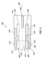
図3は、エキスパンダ(図示せず)とともに使用されるように構成されたアンカ本体410を備えるデュアルエキスパンションアンカ400の同じ実施形態を示す斜視切断図である。図3に示すアンカ400の本体410は、第1の端部412と、第2の端部414と、軸方向内腔416と、第1のタイン418および第1の拡張スロット420と、第2のタイン422および第2の拡張スロット424とを有する。軸方向内腔416は、長手方向軸430を有し、様々な形状およびサイズを備えることができる。いくつかの実施形態では、軸方向内腔は、アンカ本体410の全長にわたって1つの形状および一定の直径を有することがある。いくつかの実施形態では、図3に示すように、軸方向内腔416の形状およびサイズは、アンカ本体410の長さに沿って変化することもある。当業者なら、軸方向内腔416の形状およびサイズの変化を、エキスパンダ(図示せず)のサイズおよび形状の変化と組み合わせて使用して、アンカ本体410の所望の拡張を実現し、アンカ本体410の中のエキスパンダ(図示せず)の所望の配置を実現し、アンカ本体410の中のエキスパンダ(図示せず)の特定の移動を促進および/または防止することができることを理解するであろう。
FIG. 3 is a perspective cut-away view showing the same embodiment of a
図3に示すように、軸方向内腔416は、軸方向内腔416の長手方向軸430と平行な部分、軸方向内腔416の長手方向軸430に対して直交する部分、または軸方向内腔416の長手方向軸430に対して角度を有する部分を備えることができる。軸方向内腔416は、第1の傾斜部分432を備えることができる。第1の傾斜部分432は、アンカ本体410の第1の端部412の近傍に位置していてもよいし、あるいは図3に示すように、軸方向内腔416の長手方向軸430と平行な平行部分438によって、アンカ本体410の第1の端部412から隔てられていてもよい。第1の傾斜部分432は、エキスパンダ(図示せず)のためのカム表面となって、エキスパンダ(図示せず)の軸方向内腔416内部への移動を容易にし、それによりアンカ本体410の第1の端部412の半径を半径r4から半径r6に拡張するのを容易にするように構成することができる。
As shown in FIG. 3, the
軸方向内腔416は、第1の止め434を含むことができる。図3に示すように、第1の止め434は、アンカ本体410の長手方向軸430と平行でない壁面である。図3に示すように、第1の止め434は、エキスパンダ(図示せず)の部分と相互作用し、それによりエキスパンダ(図示せず)がいったん指定された点を超えて前進した後で引っ込むのを防止するための係合可能表面となるように、構成することができる。エキスパンダ(図示せず)が引っ込むのを防止すると、アンカ400を骨の中に永続的に配置することができるようになるので有利である。
The
第1の止めは、アンカ本体410の第1の端部412の所望の程度の展開を実現するように、第1の端部412から所望の距離に位置することができる。いくつかの実施形態では、第1の止め434は、アンカ本体410の第1の端部412が約40ミリメートル、20ミリメートル、10ミリメートル、5ミリメートル、2ミリメートル、1ミリメートル、または任意のその他の所望の拡張半径を実現するように位置づけることができる。
The first stop can be located at a desired distance from the
軸方向内腔416は、第2の傾斜部分436を備えることができる。図3に示すように、第2の傾斜部分436は、アンカ本体410の第2の端部414の近傍に位置づけることができる。第2の傾斜部分436は、エキスパンダ(図示せず)のためのカム表面となって、エキスパンダ(図示せず)の軸方向内腔416の奥への移動を容易にし、それによりアンカ本体410の第2の端部414の半径を半径r5から半径r7に拡張するのを容易にするように構成することができる。いくつかの実施形態では、アンカ本体410の第2の端部414は、約40ミリメートル、20ミリメートル、10ミリメートル、7.2ミリメートル、5ミリメートル、2ミリメートル、1ミリメートル、または任意のその他の所望の拡張半径を実現する。
The
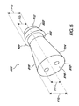
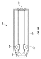
アンカは、様々なエキスパンダとともに使用することができる。図4は、第1の端部710と第2の端部712とを有する拡張部材702を備えるエキスパンダ700の一実施形態を示す図である。拡張部材702は、エキスパンダ700が長手方向に変位してアンカ本体の中に入ったときにアンカ本体を拡張させるように構成された1つまたは複数の特徴を有することができる。図4に示すエキスパンダ700は、拡張部材702の第1の端部710の近傍に位置する、半径r8を有する展開頭部714を有する。展開頭部714は、任意の所望のサイズおよび形状に合わせて製造することができる。図4に示すように、展開頭部714は、エキスパンダの第1の端部710に位置する基部716を有する円錐台を備えることができる。当業者なら、頭部714の形状およびサイズが、アンカ本体の拡張の最終的な程度および形状、ならびにアンカ本体内部でエキスパンダ700を長手方向に変位させるのに必要な力に影響を及ぼすことを理解するであろう。
Anchors can be used with a variety of expanders. FIG. 4 is a diagram illustrating one embodiment of an
いくつかの実施形態では、拡張部材702は、直径r9を有するシャフト718を含むことができる。図4に示すように、シャフト718は、拡張部材702の展開頭部714から第2の端部712に長手方向に延びることができる。シャフト718は、様々なサイズおよび形状を有することができる。図4に示すシャフト718は、円錐シャフトである。いくつかの実施形態では、シャフト718は、アンカ本体を拡張させずにアンカ本体の軸方向内腔内に嵌合するように構成された直径r9を有することができる。したがって、いくつかの実施形態では、シャフト718が軸方向内腔内に位置し、アンカ本体を拡張させるように構成された拡張部材702の特徴がアンカ本体を拡張させないように位置決めされているときには、エキスパンダ700を拡張せずにアンカ本体の軸方向内腔内に配置することができる。
In some embodiments, the
いくつかの実施形態では、図4に示すように、シャフト718はカム作用表面720を備えることができる。いくつかの実施形態では、カム作用表面720は、例えば、アンカの軸方向内腔内にエキスパンダ700を配置するのを容易にする、またはアンカ本体を拡張するのを容易にすることができる。
In some embodiments, as shown in FIG. 4, the
いくつかの実施形態では、エキスパンダ700は、エキスパンダ700への力の印加を容易にしてアンカの配備に影響を及ぼす特徴を含むことができる。いくつかの実施形態では、エキスパンダ700は、挿入器具のねじ部と螺合するように構成されたねじ穴を第2の端部712に備えることができる。アンカに対するエキスパンダ700の近位方向の移動によってアンカが配備または拡張されるアンカのいくつかの実施形態では、アンカ本体は、挿入器具に対してアンカ本体が移動するのを防止するように、挿入器具の一部分に当接することができる。エキスパンダ700は、挿入器具のアンカ本体が当接する部分と比べて比較的移動可能である挿入器具の一部分に接続することができる。いくつかの実施形態では、アンカ本体と挿入器具が当接して相互作用することと、エキスパンダ700が挿入器具の比較的移動可能な部分に接続されることとによって、エキスパンダを、アンカの遠位端部に近い第1の未配備/未拡張の位置からアンカの近位端部に向かって第2の配備/拡張された位置まで長手方向に変位させることができるようになる。
In some embodiments, the
エキスパンダは、例えば組織または縫合糸など、骨に固定する材料と係合し、これを捕捉するように構成された特徴を含むことができる。これらの特徴は、例えば頭部714、シャフト718、または任意のその他の拡張するように構成された特徴など、拡張部材702の様々な部分に位置することができる。
The expander can include features configured to engage and capture material that is secured to the bone, such as tissue or suture. These features may be located on various portions of the
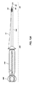
図5は、第1の端部810と第2の端部812とを有する拡張部材802を備えるシングルピースエキスパンダ800の一実施形態を示す図である。拡張部材802は、基部816を有する半径r10を有する展開頭部814と、半径r11を有する第1のシャフト部分818と、半径r12を有する展開ショルダ820と、半径r13を有する第2のシャフト部822とをさらに備える。図5に示す展開頭部814は、シングルピースエキスパンダ800の第1の端部810に基部を有する円錐台を備える。展開頭部814の基部816の半径r10が第1のシャフト部分818の半径r11より大きく、展開ショルダ820の半径r12より大きく、かつ第2のシャフト部分822の半径r13より大きいので、図5に示す展開頭部814の基部816は、径方向に見たときに、第1のシャフト部分818より高く、展開ショルダ820より高く、かつ第2のシャフト部分822より高い。展開頭部814は、アンカの適用業務の要件に応じて、様々なサイズおよび形状ならびに様々な相対サイズを備えることができる。
FIG. 5 is a diagram illustrating one embodiment of a
図5に示す拡張部材802は、シングルピースエキスパンダ800の第1の端部810と第2の端部812との間に位置する展開ショルダを備える。ただし、他の実施形態では、展開ショルダ820は、シングルピースエキスパンダ800の第2の端部812など、シングルピースエキスパンダ800の他の位置に位置していてもよい。展開ショルダ820の半径r12が第1のシャフト部分818の半径r11より大きく、かつ第2のシャフト部分822の半径r13より大きいので、図5に示す展開ショルダ820は、径方向に見たときに、第1のシャフト部分818より高く、かつ第2のシャフト部分822より高い。展開ショルダ820は、アンカの適用業務の要件に応じて、様々なサイズおよび形状ならびに様々な相対サイズを備えることができる。いくつかの実施形態では、展開ショルダ820は、展開頭部814の基部816、第1のシャフト部分818、または第2のシャフト部分822と比べて、径方向により小さくてもよいし、径方向に等しくてもよいし、径方向により大きくてもよい。同様に、シングルピースエキスパンダの他の特徴の形状および寸法も、所望の結果を得るために変更することができる。
The
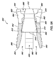
図5Aは、アンカ本体852と拡張または配備された構成のエキスパンダ800とを備えるアンカ850を示す斜視切断図である。
FIG. 5A is a perspective cut-away view showing an
図5Aに示すエキスパンダは、第1の端部810と第2の端部812とを有する拡張部材802を備える。拡張部材802は、第1の端部810に位置する基部816を有する展開頭部814をさらに備える。拡張部材は、拡張部材802の第1の端部810と拡張部材802の第2の端部812との間で、拡張部材802の第2の端部812の近傍に位置する、カム作用表面820をさらに備える。
The expander shown in FIG. 5A includes an
図5Aに示すアンカ本体852は、第1の端部854と、第2の端部856と、軸方向内腔858と、第1のタイン860および第1の拡張スロット862と、第2のタイン864および第2の拡張スロット(図示せず)とを備える。また、図5Aに示すアンカ本体852の軸方向内腔858は、第1の止め868と、カム作用当接部870とを有する。
The
図5Aに示すように、エキスパンダ800は、その全体がアンカ本体852の軸方向内腔858内に位置決めされる。詳細には、エキスパンダ800は、第1の止め868が、エキスパンダ800の展開頭部814の基部816に当接して係合することによって、エキスパンダ800がアンカ本体852の第1の端部854に向かって移動するのを防止するように、アンカ本体852の軸方向内腔858内に位置決めされる。
As shown in FIG. 5A, the
図5Aに示すように、エキスパンダ800の展開頭部814およびその他の部分は、拡張するように軸方向内腔の複数の部分と係合して、アンカ本体852を配備または拡張する。
As shown in FIG. 5A, the
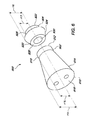
図6は、第1の拡張部材902と第2の拡張部材904とを備えるツーピースエキスパンダ900の一実施形態を示す図である。いくつかの実施形態では、ツーピースエキスパンダ900は、エキスパンダ900への力の印加を容易にしてアンカの配備に影響を及ぼす特徴を含むことができる。アンカに対するエキスパンダ900の移動によってアンカが配備または拡張されるアンカのいくつかの実施形態では、アンカ本体は、挿入器具に対してアンカ本体が移動するのを防止するように、挿入器具の一部分に当接することができる。エキスパンダ900の各ピースは、挿入器具のアンカ本体が当接する部分と比べて比較的移動可能である挿入器具の1つまたは複数の部分に接続することができる。いくつかの実施形態では、アンカ本体と挿入器具が当接して相互作用することと、エキスパンダ900の各ピースが接続されることとによって、挿入器具の比較的移動可能な部分がエキスパンダの各ピースを、第1の未配備/未拡張の位置から第2の配備/拡張された位置まで長手方向に変位させることができる。
FIG. 6 is a diagram illustrating one embodiment of a two-
第1の拡張部材は、第1の端部910と、第2の端部912とを有する。第1の拡張部材902は、半径r14で画定される基部916を有する第1の展開頭部914と、半径r15で画定される第1のシャフト部分918とを有する。図6に示す第1の展開頭部914は、ツーピースエキスパンダ900の第1の拡張部材902の第1の端部910に基部916を有する円錐台を備える。第1の展開頭部914の基部916の半径r14が第1のシャフト部分918の半径r15より大きいので、図6に示す第1の展開頭部914の基部916は、径方向に見たときに、第1のシャフト部分918より高い。第1の展開頭部914は、アンカの適用業務の要件に応じて、様々なサイズおよび形状ならびに様々な相対サイズを備えることができる。
The first expansion member has a
第2の拡張部材904は、第1の端部920と、第2の端部922とを有する。第2の拡張部分904は、半径r16で画定される基部926を有する第2の展開頭部924と、半径r17で画定される第2のシャフト部分928とを有する。図6に示す第2の展開頭部924は、ツーピースエキスパンダ900の第2の拡張部材904の第1の端部920に基部926を有する円錐台を備える。第2の展開頭部924の基部926の半径r16が第2のシャフト部分928の半径r17より大きいので、図6に示す第2の展開頭部924の基部926は、径方向に見たときに、第2のシャフト部分928より高い。第2の展開頭部924は、アンカの適用業務の要件に応じて、様々なサイズおよび形状ならびに様々な相対サイズを備えることができる。第1の展開頭部914および第2の展開頭部924は、アンカの適用業務の要件に応じて、様々なサイズおよび形状ならびに様々な相対サイズを備えることができる。いくつかの実施形態では、第1の展開頭部914の基部916は、第2の展開頭部924の基部926と比べて、径方向により小さくてもよいし、径方向に等しくてもよいし、径方向により大きくてもよい。同様に、第1のシャフト部分918および第2のシャフト部分928の相対サイズは、互いに対して、かつ第1の展開頭部914および第2の展開頭部924に対して様々にすることができる。
The
ツーピースエキスパンダ900のいくつかの実施形態では、第2の拡張部材は、貫通孔930を備えることができる。この貫通孔は、第1の拡張部材902に取り付けられるように構成された挿入器具の一部分を第2の拡張部材904の中に通すことができるようなサイズおよび形状にすることができる。
In some embodiments of the two-
いくつかの追加の実施形態では、第2の拡張部材904の第2の端部922は、挿入器具の一部分に当接して接触するように構成することができる。いくつかの実施形態では、挿入器具のこの部分は、第2の拡張部材904がアンカ本体に対して相対的に移動することを可能にするように構成することができる。
In some additional embodiments, the
図6Aは、アンカ本体952とツーピースエキスパンダ900とを備える、拡張または配備された構成のアンカ950を示す斜視切断図である。
FIG. 6A is a perspective cut-away view showing an
図6Aに示すツーピースエキスパンダ900は、第1の拡張部材902と第2の拡張部材904とを備える。第1の拡張部材902は、第1の端部910と第2の端部912とを有し、第1の端部910に位置する基部916を有する第1の展開頭部914を備える。第2の拡張部材904は、第1の端部920と第2の端部922とを有し、第1の端部920に位置する基部926を有する第2の展開頭部924を備える。
A two-
図6Aに示すアンカ本体952は、第1の端部954と、第2の端部956と、軸方向内腔958と、第1のタイン960および第1の拡張スロット962と、第2のタイン964および第2の拡張スロット(図示せず)とを備える。また、図6Aに示すアンカ本体952の軸方向内腔958は、第1の止め968と第2の止め970とを有する。
The
図6Aに示すように、エキスパンダ900は、その全体がアンカ本体952の軸方向内腔958内に位置決めされる。詳細には、エキスパンダ900は、第1の止め968が、第1の拡張部材902の第1の展開頭部914の基部916に当接して係合することによって、第1の拡張部材902がアンカ本体952の第1の端部954に向かって移動するのを防止するように、アンカ本体952の軸方向内腔958内に位置決めされる。エキスパンダ900の第2の拡張部材904は、第2の止め970が、第2の拡張部材904の第2の展開頭部924に当接して係合することによって、第2の拡張部材904がアンカ本体952の第2の端部956に向かって移動するのを防止するように、アンカ本体952の軸方向内腔958内に位置決めされる。図6Aにさらに示すように、第1の拡張部材902は、第2の拡張部材904と接触していない。ただし、当業者なら、いくつかの実施形態では、第1の拡張部材902が第2の拡張部材904と接触していてもよいことを理解するであろう。
As shown in FIG. 6A, the
図6Aに示すように、第1の展開頭部914および第2の展開頭部924は、それぞれ、拡張するように軸方向内腔の複数の部分と係合して、アンカ本体952の第1の端部954に位置する第1のタイン960および第1の拡張スロット962ならびにアンカ本体952の第2の端部956に位置する第2のタイン964および第2の拡張スロット966を配備または拡張する。
As shown in FIG. 6A, the
上述のデュアルエキスパンションアンカは、天然材料または人工材料など、様々な材料で構成することができる。デュアルエキスパンションアンカは、金属、プラスチック、ポリマー、複合材、またはその他の材料で構成することができる。いくつかの実施形態では、アンカは、生体適合性のポリマー、プラスチック、または金属で構成される。他の実施形態は、全体または一部が生体適合性の非金属物質である組織捕捉アンカを含む。ポリエーテルケトン(PEK)、ポリエーテルエーテルケトン(PEEK)、ポリエーテルイミド(ULTEM)、超高分子量ポリエチレン(UHMPE)、ポリフェニレン、または何らかのその他の当業者に既知のエンジニアリングポリマー材料などの生体適合性材料を、使用することができる。非金属のアンカシステムは、例えばMRIアーチファクトを解消するなど、特定の利点をもたらすことができる。 The dual expansion anchor described above can be composed of various materials, such as natural or artificial materials. The dual expansion anchor can be composed of metal, plastic, polymer, composite, or other material. In some embodiments, the anchor is composed of a biocompatible polymer, plastic, or metal. Other embodiments include tissue capture anchors that are wholly or partly biocompatible non-metallic materials. Biocompatible materials such as polyetherketone (PEK), polyetheretherketone (PEEK), polyetherimide (ULTEM), ultra high molecular weight polyethylene (UHMPE), polyphenylene, or some other engineering polymer material known to those skilled in the art Can be used. Non-metallic anchor systems can provide certain advantages, such as eliminating MRI artifacts.
組織捕捉
いくつかの実施形態は、上述のアンカを使用して、アンカを骨に挿入する前に腱または靱帯などの軟組織を捕捉して固定することを含む。いくつかの実施形態では、軟組織は、軟組織または軟組織束の周りに通したループ状の縫合糸を用いてアンカに固定することができる。いくつかの実施形態では、固定構成を実現するための縫合糸の操作は、アンカと連動する縫合糸グラバを用いて実施することができる。いくつかの実施形態では、縫合糸グラバは、アンカの遠位端部から延びる。いくつかの実施形態では、縫合糸グラバは、縫合糸リムをアンカ内に引き込むようにアンカ内に引き込み可能である。適当な縫合糸グラバとしては、ワイヤループ、ワイヤフック、ピンチャ機構、または任意のその他の適当な構造などが挙げられるが、これらに限定されるわけではない。いくつかの実施形態では、縫合糸グラバは、ニチノールワイヤで構成される。本明細書に記載する特定の縫合糸グラバ(例えばワイヤループ)を利用する実施形態のいずれにおいても、任意のその他の適当な縫合糸グラバを利用することができることを理解されたい。
Tissue Capture Some embodiments include capturing and fixing soft tissue, such as tendons or ligaments, prior to inserting the anchor into bone using the anchor described above. In some embodiments, the soft tissue can be secured to the anchor using a looped suture threaded around the soft tissue or soft tissue bundle. In some embodiments, manipulation of the suture to achieve a fixed configuration can be performed using a suture grabber that is interlocked with an anchor. In some embodiments, the suture grabber extends from the distal end of the anchor. In some embodiments, the suture grabber can be retracted into the anchor to retract the suture rim into the anchor. Suitable suture grabbers include, but are not limited to, wire loops, wire hooks, pincher mechanisms, or any other suitable structure. In some embodiments, the suture grabber is composed of nitinol wire. It should be understood that any other suitable suture grabber can be utilized in any of the embodiments utilizing a particular suture grabber (eg, a wire loop) described herein.
図17Aから図19Eは、挿入器具1000に接続することができるアンカ2500に例えば腱または靱帯などの軟組織を固定する方法の実施形態を示す図である。アンカ2500は、上述のアンカのうちのいずれか、または任意のその他の所望のアンカを備えることができる。図17Aに示すように、アンカ2500は、縫合糸757とワイヤループ788とを含むエキスパンダ750を備える。縫合糸757は、アンカから、アンカのエキスパンダ750の遠位端部の第1の穴を通って延びる。ワイヤループ788は、アンカから、アンカのエキスパンダ750の遠位端部の第2の穴を通って延びる。縫合糸は、アンカ2500の内部および挿入器具1000の内部を通って執刀医が保持して操作することができる位置まで近位方向に延びることもできる。同様に、ワイヤループ788の端部も、アンカ2500の内部および挿入器具1000の内部を通って執刀医が保持して操作することができる位置まで近位方向に延びることができる。図17Aに示すように、アンカ2500は、第1の関節鏡検査口2502を通して、例えば腱2504の近傍の位置まで挿入することができる。アンカ2500が腱2504の近傍に位置決めされた後、プロセスは図17Bに進み、第2の関節鏡検査口2506を通してワイヤループ788を引っ張ることができる。いくつかの実施形態では、第1の関節鏡検査口2502または第2の関節鏡検査口2506を通して器具に到達することができ、この器具を使用して、ワイヤループ788を把持し、第2の関節鏡検査口2506を通してワイヤループを引っ張ることができる。
FIGS. 17A-19E illustrate an embodiment of a method of securing a soft tissue, such as a tendon or ligament, to an
第2の関節鏡検査口2506を通してワイヤループ788を引っ張った後で、プロセスは、図17Cに進み、縫合糸757を例えば腱2504の下に通すことができる。いくつかの実施形態では、第1の関節鏡検査口2502または第2の関節鏡検査口2506を通して器具に到達することができ、この器具を使用して、縫合糸757を把持して腱2504の下に通すことができる。縫合糸757を腱2504の下に通した後で、プロセスは、図17Dに進み、第2の関節鏡検査口2506を通して縫合糸757を引っ張る。上述のように、器具は、関節鏡検査口2502、2506のうちの一方を介して縫合し757にアクセスし、第2の関節鏡検査口から縫合し757を引き出すことができる。第2の関節鏡検査口2506を通して縫合糸757を引っ張った後で、縫合糸757を、ワイヤループ788に通す、または結びつけることができる。
After pulling the
次に、ワイヤループ788を、(例えばアンカ挿入器1000の中に延びるワイヤの端部を引っ張ることによって)関節鏡検査口2506からアンカ2500の内部および挿入器1000の内部を通して引き込み、挿入器1000の近傍で患者の体から引き出すことができる。これらの特徴を通してワイヤループ788を引き込むと、これらの特徴を通してポート2506を通って延びる縫合糸757のリムを引き込むこともできるので有利である。ワイヤループ788を引き込み、それとともに縫合糸757を引っ張った後で、プロセスは、図17Eに進み、2つの縫合糸リムがアンカ2500の内部および挿入器1000の内部の中に延びた状態で腱2504の周りにループを形成している縫合糸757によって、腱2504がアンカ2500に固定される。いくつかの実施形態では、2つの縫合糸リムに張力を生じさせることによって、腱を一時的に、かつ調節可能にアンカに固定することができる。執刀医が縫合糸リムを引っ張ることによって手作業でこの張力を生じさせてもよいし、あるいは、縫合糸リムを挿入器1000のハンドルに位置する縫合糸クリートなど挿入器1000の一部分に固定してもよい。
Next, the
図18Aから図18Eは、軟組織をアンカ2500に固定する別の方法を示す図である。図18Aに示すように、アンカ2500は、ワイヤループ788と縫合糸757とを備える。縫合糸757は、アンカから、アンカのエキスパンダ750の遠位端部の第1の穴を通って延びる。ワイヤループ788は、アンカから、アンカのエキスパンダ750の遠位端部の第2の穴を通って延びる。縫合糸は、アンカ2500の内部および挿入器具1000の内部を通って執刀医が保持して操作することができる位置まで近位方向に延びることもできる。同様に、ワイヤループ788の端部も、アンカ2500の内部および挿入器具1000の内部を通って執刀医が保持して操作することができる位置まで近位方向に延びることができる。縫合糸757は、第1の関節鏡検査口2502を通して、例えば腱2504の近傍の位置まで挿入される。図18Aにさらに示すように、縫合糸757は、いくつかの実施形態では、アンカ2500のエキスパンダ750を通って第1の関節鏡検査口2502から出るように延びることができる。いくつかの実施形態では、縫合糸757の2つのリムは、例えば挿入器1000のクリートに固定することができる。
18A-18E are diagrams illustrating another method of securing soft tissue to
アンカ2500が腱2504の近傍に位置決めされた後、プロセスは図18Bに進み、ワイヤループ788を例えば腱2504の下に通す。ワイヤループ788を腱2504の下に通した後で、プロセスは、図18Cに進み、第2の関節鏡検査口2506を通してワイヤループ788を引っ張る。第2の関節鏡検査口2506を通してワイヤループ788を引っ張った後で、プロセスは、図18Dに進み、縫合糸757を、挿入器のクリートから外すことができ、第2の関節鏡検査口2506を通して引っ張って、ワイヤループ788に通すことができる。次に、ワイヤループ788を、(例えばアンカ挿入器1000の中に延びるワイヤの端部を引っ張ることによって)関節鏡検査口2506からアンカ2500の内部および挿入器1000の内部を通して引き込み、挿入器1000の近傍で患者の体から引き出すことができる。これらの特徴を通してワイヤループ788を引き込むと、これらの特徴を通してポート2506を通って延びる縫合糸757のリムを引き込むこともできるので有利である。ワイヤループ788を引き込み、それとともに縫合糸757を引っ張った後で、プロセスは、図18Eに進み、2つの縫合糸リムがアンカ2500の内部および挿入器1000の内部の中に延びた状態で腱2504の周りにループを形成している縫合糸757によって、腱2504がアンカ2500に固定される。いくつかの実施形態では、2つの縫合糸リムに張力を生じさせることによって、腱を一時的に、かつ調節可能にアンカに固定することができる。執刀医が縫合糸リムを引っ張ることによって手作業でこの張力を生じさせてもよいし、あるいは、縫合糸リムを挿入器1000のハンドルに位置する縫合糸クリートなど挿入器1000の一部分に固定してもよい。
After the
図19Aから図19Eは、アンカ2500に軟組織を固定するさらに別の方法を示す図である。図19Aに示すように、アンカ2500は、ワイヤループ788を含むエキスパンダ750を備える。ワイヤループ788は、アンカから、アンカのエキスパンダ750の遠位端部の第1の穴を通って延びる。ワイヤループ788の端部は、アンカ2500の内部および挿入器具1000の内部を通って執刀医が保持して操作することができる位置まで近位方向に延びることができる。図19Aに示すように、アンカ2500は、第1の関節鏡検査口2502を通して、例えば腱2504の近傍の位置まで挿入することができる。アンカ2500が腱2504の近傍に位置決めされた後、プロセスは図19Bに進み、縫合糸757を第2の関節鏡検査口2506に通し、腱2504の周りに通す。縫合糸757を第2の関節鏡検査口2506に通すことは、いくつかの器具および技術のうちのいずれかを使用して行うことができる。縫合糸757を腱2504の周りに通した後で、プロセスは、図19Cに進み、第2の関節鏡検査口2506を通してワイヤループ788を引っ張る。第2の関節鏡検査口2506を通してワイヤループ788を引っ張った後で、縫合糸757を、ワイヤループ788に通すことができる。いくつかの実施形態では、十分に長い縫合糸757をワイヤループ788に通して、ワイヤループ788が第2の関節鏡検査口2506を通してアンカ2500および挿入器具1000を通って確実に縫合糸757を引き込むことができるようにする。縫合糸757をワイヤループ788に通した後で、プロセスは、図19Dに進み、ワイヤループ788を、(例えばアンカ挿入器1000の中に延びるワイヤの端部を引っ張ることによって)第2の関節鏡検査口2506から引き込むことができる。図19Dに示すように、第2の関節鏡検査口2506を通してワイヤループ788を引き込むと、第2の関節鏡検査口2506を通して縫合糸757の一部分も引き込まれる。次に、ワイヤループ788を、(例えばアンカ挿入器1000の中に延びるワイヤの端部を引っ張ることによって)エキスパンダ750、アンカ2500の内部、および挿入器具1000の内部を通してさらに引き込み、挿入器1000の近傍で患者の体から引き出すことができる。これらの特徴を通してワイヤループ788を引き込むと、これらの特徴を通してポート2506を通って延びる縫合糸757のリムを引き込むこともできるので有利である。ワイヤループ788を引き込み、それとともに縫合糸757を引っ張った後で、プロセスは、図19Eに進み、2つの縫合糸リムがアンカ2500の内部および挿入器1000の内部の中に延びた状態で腱2504の周りにループを形成している縫合糸757によって、腱2504がアンカ2500に固定される。いくつかの実施形態では、2つの縫合糸リムに張力を生じさせることによって、腱を一時的に、かつ調節可能にアンカに固定することができる。執刀医が縫合糸リムを引っ張ることによって手作業でこの張力を生じさせてもよいし、あるいは、縫合糸リムを挿入器1000のハンドルに位置する縫合糸クリートなど挿入器1000の一部分に固定してもよい。
19A to 19E are diagrams showing still another method of fixing soft tissue to the
アンカ挿入器具
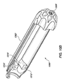
図7は、挿入器具の一実施形態の個々の構成要素を示す図である。挿入器具は、その挿入器具がアンカを挿入し、次いでそのアンカを配備するように相互作用することを可能にするように構成された様々な特徴を備える。挿入器具の一実施形態は、特定のアンカ構成または特定のスプレッダ構成で使用されるように構成することができる。図10は、シングルピースエキスパンダとともに使用されるように構成された挿入器の実施形態を示す図である。この挿入器具は、内側ロッドまたは内側管1100と、外側管1200と、ハンドル本体1300と、ねじ付きアクチュエータシャフト1400と、配備ノブ1500とを備える。いくつかの実施形態では、挿入器1000は、製造中にアンカに結合される。好ましい実施形態では、挿入器具は使い捨て式である。
Anchor Insertion Tool FIG. 7 shows the individual components of one embodiment of the insertion tool. The insertion instrument comprises various features configured to allow the insertion instrument to interact to insert the anchor and then deploy the anchor. One embodiment of the insertion tool can be configured for use with a particular anchor configuration or a particular spreader configuration. FIG. 10 illustrates an embodiment of an inserter configured to be used with a single piece expander. The insertion instrument includes an inner rod or
挿入器具1000は、図1から図3に示すアンカなどのアンカを挿入して操作するように設計される。いくつかの実施形態では、アンカは、パッケージングの前に挿入器具に取り付けられるように製造される。その他の実施形態では、組織捕捉アンカは、挿入前に挿入器具に結合される。基本構成では、挿入器具は、以下のように組み立てられる。すなわち、挿入器具1000は、内側ロッド1100が外側管1200内に配置されるように構成される。外側管は、アンカの近位端部に適合するように構成される。内側ロッド1100は、外側管1200を通って延び、エキスパンダの近位穴のねじおよび内側ロッド1100の遠位端部のねじの両方を介してエキスパンダに取り付けられるように構成される。外側管1200の近位端部は、ハンドル1300に接続され、内側ロッド1100は、外側管1200の近位端部を通って延びて、ねじ付きアクチュエータシャフト1400の中に螺入する。アクチュエータシャフト1400は、ハンドル1300の近位端部を越えて延び、そこで配備ノブ1500に固定されるように構成される。
The
挿入器具の個々の構成要素について、以下で詳細にさらに説明する。 The individual components of the insertion tool are further described in detail below.
図7Aは、ツーピースエキスパンダとともに使用されるように構成された挿入器の実施形態を示す図である。図7に示す挿入器具1000と同様に、挿入器具1000aは、内側ロッドまたは内側管1100aと、外側管1200aと、ハンドル本体1300aと、ねじ付きアクチュエータシャフト1400aと、配備ノブ1500aとを備える。いくつかの実施形態では、挿入器具1000aの内側ロッドまたは内側管1100aと、外側管1200aと、ハンドル本体1300aと、ねじ付きアクチュエータシャフト1400aと、配備ノブ1500aとは、図7のそれらの特徴に関連して説明したように、互いに適合することができる。いくつかの実施形態では、挿入器具1000aの内側ロッドまたは内側管1100a、外側管1200a、ハンドル本体1300a、ねじ付きアクチュエータシャフト1400a、および配備ノブ1500aのうちのいくつかまたは全ては、ツーピースエキスパンダとの使用を容易にするように構成された追加の特徴を含むことができる。これらの違いとしては、例えば外側管1200aまたは挿入器具1000aの任意の他の特徴に位置する追加の特徴などが挙げられる。外側管1200aの追加の特徴については、以下でさらに詳細に説明する。
FIG. 7A illustrates an embodiment of an inserter configured to be used with a two-piece expander. Similar to the
図8は、内側ロッド1100の実施形態を示す斜視図である。いくつかの実施形態では、内側ロッドは、内側管である。内側ロッドは、エキスパンダに固定されるように構成された遠位端部と、例えばアクチュエータシャフト1400など、挿入器の他の構成要素と相互作用するように構成された近位端部とを備える。内側ロッド1100は、近位端部1120が外側管1200を通ってハンドル1300の中へ前進し、そこでねじを介してアクチュエータシャフト1400内にさらに固定されるように構成される。内側ロッド1100の遠位端部1105は、アンカ本体の中央穴を通って前進し、その後アンカが完全に配備されて、内側ロッド1100がアンカから分離されるまでエキスパンダに固定されるように構成される。いくつかの実施形態では、遠位端部1105は、例えばねじ1110など、エキスパンダと係合するように構成された特徴を備えることができる。内側ロッド1100の本体1125は、外側管1200内で滑動して位置決めされるように構成される。
FIG. 8 is a perspective view showing an embodiment of the
内側ロッド1100は、アンカ本体の中央穴を通って延びた後で、エキスパンダに結合される。一実施形態では、内側ロッド1100は、内側ロッド1100の端部のねじおよびエキスパンダの近位端部内のねじを介してエキスパンダと結合される。他の実施形態では、内側ロッド1100は、接着剤、溶接、または摩擦嵌めなど、その他の固定機構を介してエキスパンダに結合することもできる。
The
図9は、外側管1200の実施形態を示す図である。外側管1200は、その近位端部1250で、ねじ1225を介してハンドルの遠位端部に取り付けられる。外側管1200の遠位端部1210は、内側ロッドが外側管1200の遠位端部1210の開口1220を通って外側管1200の中に引き込まれ、そこでエキスパンダに固定されるように構成される。内側管が、エキスパンダが適所にロックされるのに十分な距離を前進したとき、またはそれ以上前進することができなくなったとき、外側管1200の遠位表面は、アンカ本体の近位表面と面接触する。配備ノブを引き続き回転させ、アクチュエータシャフトを前進させて、内側ロッドがさらに外側管の中に引き込まれると、内側ロッドがエキスパンダのねじをすり潰し、挿入器具がアンカから外れる。
FIG. 9 is a diagram illustrating an embodiment of the
図9Aは、ツーピースエキスパンダとともに使用されるように構成された外側管1200aの実施形態を示す図である。外側管1200aは、その近位端部1250aで、ねじ1225aを介してハンドルの遠位端部に取り付けられる。外側管1200aの遠位端部1210aは、内側ロッドが外側管1200aの遠位端部1210aの開口1220aを通って外側管1200aの中に引き込まれ、そこでエキスパンダに固定されるように構成される。ツーピースエキスパンダとともに使用されるように構成された外側管1200aのいくつかの実施形態では、外側管の遠位端部1210aは、第1の当接部1212aを備える。いくつかの実施形態では、第1の当接部1212aは、デュアルエキスパンションアンカ100、400の第2の端部114、414と当接して係合するように構成される。
FIG. 9A illustrates an embodiment of an outer tube 1200a configured to be used with a two-piece expander. Outer tube 1200a is attached at its
いくつかの実施形態では、外側管1200aの遠位端部1210aは、第1の基部1260aと第1の突出当接部1262aとを備える。いくつかの実施形態では、第1の基部1260aは、アンカ100、400の第2の端部114、414の近傍の軸方向内腔116、416の部分の中に嵌合するようなサイズおよび寸法である。第1の基部1260aは、例えば、デュアルエキスパンションアンカ100、400が配備または拡張された構成であるときにデュアルエキスパンションアンカ100、400の第2の端部114、414の近傍の軸方向内腔116、416の部分に滑動可能に進入するような、あるいはデュアルエキスパンションアンカ100、400が未配備または未拡張の構成であるときにデュアルエキスパンションアンカ100、400の第2の端部114、414の近傍の軸方向内腔116、416の部分に滑動可能に進入するような、サイズおよび形状にすることができる。いくつかの実施形態では、外側管1200aの第1の突出当接部1262aは、第2の拡張部材904の第2の端部922に当接して係合するように構成される。
In some embodiments, the
いくつかの実施形態では、外側管1200aの遠位端部1210aは、第2の基部1270aと第2の突出当接部1272aとを備える。いくつかの実施形態では、第2の基部1270aは、アンカ100、400の第2の端部114、414の近傍の軸方向内腔116、416の部分の中に嵌合するようなサイズおよび寸法である。いくつかの実施形態では、第2の基部1270aは、第2の拡張部材904の貫通孔を通って滑動可能に延びるように構成される。いくつかの実施形態では、第2の基部1270aは、第2の拡張部材904を通って延びるようなサイズおよび構成にすることができる。いくつかの実施形態では、第2の基部1270aは、デュアルエキスパンションアンカがその配備または拡張構成であるときに第2の突出当接部1272aが第1の拡張部材902の第2の端部912と当接するアンカ100、400の軸方向内腔116、416内の点で終端する。
In some embodiments, the
いくつかの実施形態では、外側管1200aの遠位端部1210aの特徴は、ツーピースエキスパンダ900を有するデュアルエキスパンションアンカ100、400の配備を容易にするように構成される。いくつかの実施形態では、デュアルエキスパンションアンカ100、400は、挿入器具1000aの外側管1200aの遠位端部1210aに位置決めすることができる。詳細には、いくつかの実施形態では、デュアルエキスパンションアンカ100、400の第2の拡張部材904は、第1の突出当接部1262aに当接することができる。いくつかの実施形態では、第2の基部1270aおよび内側管1100aはデュアルエキスパンションアンカ900の第2の拡張部材904の貫通孔を通って延びることができる。いくつかの実施形態では、アンカ本体110、410の第2の端部114、414は、ツーピースエキスパンダ900の第2の拡張部材904と接触することができ、デュアルエキスパンションアンカ100、400の第1の端部112、412は、ツーピースエキスパンダ900の第1の拡張部材902と接触することができる。いくつかの実施形態では、ツーピースエキスパンダ900の第1の拡張部材902は、内側管1100aに固定することができる。内側管1100aが長手方向に変位して、アンカ100、400を拡張/配備すると、内側管1100aは、ツーピースエキスパンダ900の第1の拡張部材902に力を印加し、第1の突出当接部1262aは、ツーピースエキスパンダ900の第2の拡張部材904に反作用力を印加する。これらの力を印加することにより、ツーピースエキスパンダ900の第1の拡張部材902および第2の拡張部材904の両方が配備位置になるまで、ツーピースエキスパンダ900の第1の拡張部材902および第2の拡張部材904を変位させることができる。さらに詳細には、ツーピースエキスパンダ900の第1の拡張部材902は、力が印加された状態で、ツーピースエキスパンダ900の第1の拡張部材902が第2の突出当接部1272aと接触するまで変位することができる。さらに、ツーピースエキスパンダ900の第2の拡張部材904は、力が印加された状態で、アンカ本体110、410の第2の端部114、414が外側管1200aの遠位端部1210aの第1の当接部1212aと接触するまで変位することができる。いくつかの実施形態では、第2の突出当接部1272aは、第1の突出当接部1262aに対して相対的に位置決めすることができ、デュアルエキスパンションアンカ100、400は、アンカ本体110、410の第2の端部114、414が外側管1200aの遠位端部1210aの第1の当接部1212aと接触した後でツーピースエキスパンダ900の第1の拡張部材902が第2の突出当接部1272aとのみ接触するように、設計することができる。ツーピースエキスパンダ900の第1の拡張部材902および第2の拡張部材904の両方がそれぞれの配備/拡張された位置に到達した後で、内側管1100aは、ツーピースエキスパンダ900の第1の拡張部材902から分離され、挿入器具1000aとアンカ100、400との間の接続が終了する。
In some embodiments, the features of the
図10Aおよび図10Bは、ハンドル本体1300の実施形態を示す図である。ハンドル本体1300は、ハンドルピース1302と蓋ピース1304とを備えることができる。図10Aは、ハンドル本体1300の蓋ピース1304の側面図である。ハンドル1300の近位端部は、ノブをしっかりと保持する隆起1330を介して配備ノブを受けるように構成される。アクチュエータシャフトは、ハンドル本体1300の中に収容される。1組のフラットブラケットまたはブレース1310が、アクチュエータシャフトをハンドル1300内に固定する。ハンドル1300の遠位端部は、開口1350においてねじを介して外側管を受けるように構成される。外側管は、その遠位端部においてハンドル1300に永続的に固定される。
10A and 10B are diagrams illustrating an embodiment of the
図10Bは、ハンドル1300のハンドル部分1302の一実施形態を示す斜視図である。ハンドル部分1302は、外側管1200のねじ1225と螺合するねじ穴を含む。図10Bに示すハンドル部分1302は、さらに、ブレース受け開口1312を含む。ハンドル部分1302は、さらに、平坦表面1315を含む。
FIG. 10B is a perspective view illustrating one embodiment of a handle portion 1302 of the
図11は、ねじ付きアクチュエータシャフト1400を示す図である。アクチュエータシャフト1400は、内側ロッド1100を受けるように構成されたねじ穴1410を備えた遠位端部1405と、内側ロッド1100を前進させるように構成されたシャフトの本体の第2のねじ部1425と、配備ノブ1500内に固定されるように構成された近位端部1420とで構成される。アクチュエータ1400のねじ1425は、各面に1つずつ2つの平坦領域1430を有し、この平坦表面には、ねじはない。これらの平坦領域1430は、アクチュエータ1400がハンドル内で回転することができないように、ハンドル1300の平坦表面1315の内側に嵌合する。
FIG. 11 shows a threaded
アクチュエータシャフト1400の本体は、シャフト1400が内側管1100を前進させることができるようにするねじ1425を有する構成である。アクチュエータシャフト1400の本体は、完全な円形ではなく、配備ノブ1500が回されて、シャフト1400がノブ1500を介して前進したときにアクチュエータシャフト1400自体が回転することができないようにハンドル本体1300に嵌合する平坦な側面1430を有する長円形である。したがって、ねじは、シャフトの全周に形成されるのではなく、シャフトの平坦側面で平坦になっている。アクチュエータシャフトは、同軸システムとして構成される。すなわち、エキスパンダと、内側管1100と、アクチュエータ1400とが、1つのピースとして動作するように構成される。ハンドル内の平坦表面1315によって、ハンドル1300内でアクチュエータシャフト1400自体が回転することができないように、アクチュエータシャフト1400は面上に留まる。内側管1100の近位端部は、ねじを介してアクチュエータシャフト1400の遠位端部と結合する。
The body of the
図12に進むと、配備ノブ1500が示してある。配備ノブ1500は、ねじ1505を有する構成の中央穴1510と、ハンドル1300の対応する隆起部1330によって受けられるように構成された溝1530とを備える。中央穴1510の中のねじ1505は、アクチュエータシャフト1400を受けるように構成される。配備ノブ1500は、アクチュエータシャフト1400を介して内側ロッド1100を配備ノブ1500に対して相対的に前進させるように構成される。アクチュエータシャフト1400は、その近位端部において、配備ノブ1500の遠位端部に中央穴1510の中のねじ1505を介して結合される。アクチュエータシャフト1400は、内側ロッド1100の近位端部がアクチュエータシャフトの遠位端部の中へねじを介して進入することによって内側ロッド1100に取り付けられ、配備ノブ1500が回転したときにシャフト1400の機構が内側ロッド1100を近位方向に前進させ、エキスパンダがアンカ本体の中へ進入して、アンカ本体を骨の中へ拡張させてアンカを固定するようになっている。
Proceeding to FIG. 12, a
一実施形態では、配備ノブ1500は、ねじ1505を有し、ノブ1500の溝1530がハンドル本体1300の近位端部の隆起部1330と嵌合することによってアクチュエータシャフトを受ける。配備ハンドルが回転すると、アンカ本体が配備されて適所にロックされるまで、アクチュエータシャフト1400が近位方向に前進する。
In one embodiment,
図13Aは、挿入器具1000に結合されたデュアルエキスパンションアンカ400の一実施形態を示す図である。アンカ400は、アンカ本体410とエキスパンダ480とを備える。図13Aに示すように、エキスパンダ480は、ワイヤループ788と縫合糸757とを備える。図13Aにさらに示すように、挿入器具1000は、クリート1450を含む。いくつかの実施形態では、挿入器具1000は、1つまたは複数のクリート1450を備えることができ、これらのクリートは、例えば挿入器具1000の任意の所望の部分に位置することができる。いくつかの実施形態では、クリート1450は、縫合糸757を固定し易くするように構成することができ、詳細には、クリート1450は、縫合糸757の一端または両端を固定するために使用することができる。1つの特定の実施形態では、挿入器具1000は、ハンドル本体1300の側面上に位置する第1のクリートと、ハンドル本体1300上のハンドル本体1300と外側管1200との間の位置に位置することができる第2のクリートとを備えることができる。このような実施形態では、第1のクリートは、縫合糸757の第1の端部を固定することができ、第2のクリートは、縫合糸757の第2の端部を固定することができる。当業者なら、骨に固定する材料と係合してこれを捕捉するように構成された上記に開示した特徴またはその他の特徴のうちのいずれも、挿入器具1000に結合されたデュアルエキスパンションアンカ400と組み合わせて使用することができることを理解するであろう。
FIG. 13A illustrates one embodiment of a
挿入器具1000は、図示のように、外側管1200と、ハンドル1300と、配備ノブ1500とを含む。内側ロッド1100は、外側管1200の中に位置決めされ、外側管は、アンカ本体410と面一である。外側管1200は、挿入および配備の間、安定してアンカ本体410を保持することができる。内側ロッド1100は、アンカ本体410を通って延び、ねじを介してエキスパンダ480と結合する。エキスパンダ480は、配備ノブ1500を回転させることにより、内側ロッド1100によってアンカ本体410の遠位端部を通って前進するように構成される。
The
別の実施形態では、内側ロッド1100は、エキスパンダ480を通って延びる。内側ロッド1100は、鋭く尖った先端を有する構成であり、アンカ本体410が完全に配備される前に、内側ロッド1100の先端が組織に突き刺さる、または組織を捕捉して、骨の穴の中に固定するようになっている。
In another embodiment, the
内側ロッド1100は、エキスパンダ480をアンカ本体410の中央内腔416の中に引き込んで、アンカ本体410を完全に拡張させる機構を提供する。組織捕捉アンカ400の配備中、内側ロッド1100は、エキスパンダがアンカ本体にロックされるまでねじ運動によって継続的に前進する。配備ノブ1500が回転し続け、内側ロッド1100がエキスパンダ480のねじを引っ張り続けると、内側ロッド1100は、エキスパンダ480の内側のねじをすり潰し、挿入器具1000はアンカ本体410から外れる。ねじの削り屑は、外側管1200の中に収容される。
The
図14は、アンカ100および挿入器1000を示す展開図である。組織捕捉アンカ100は、アンカ本体110とエキスパンダ180とを備える。挿入器具1000は、図示のように、外側管1200と、ハンドル1300と、配備ノブ1500とを含む。内側ロッド1100は、外側管1200の中に位置決めされ、外側管は、アンカ本体110と面一である。外側管1200は、挿入および配備の間、安定してアンカ本体110を保持することができる。内側ロッド1100は、アンカ本体110を通って延び、ねじを介してエキスパンダ180と結合する。エキスパンダ180は、配備ノブ1500を回転させることにより、内側ロッド1100によってアンカ本体110の遠位端部を通って前進するように構成される。
FIG. 14 is a development view showing the
内側ロッド1100は、エキスパンダ180をアンカ本体110の中央穴の中に引き込んで、アンカ本体110を完全に拡張させる機構を提供する。組織捕捉アンカ100の配備中、内側ロッド1100は、エキスパンダがアンカ本体にロックされるまでねじ運動によって継続的に前進する。配備ノブ1500が回転し続け、内側ロッド1100がエキスパンダ180のねじを引っ張り続けると、内側ロッド1100は、エキスパンダ180の内側のねじをすり潰し、挿入器具1000はアンカ本体110から外れる。ねじの削り屑は、外側管1200の中に収容される。
The
いくつかの実施形態では、予め取り付けられた送出しハンドルが設けられる。いくつかの実施形態では、挿入器具または送出しハンドルは、使い捨て式である。他の実施形態では、挿入器具は、殺菌し、リロードし、再使用することができる。 In some embodiments, a pre-attached delivery handle is provided. In some embodiments, the insertion instrument or delivery handle is disposable. In other embodiments, the insertion tool can be sterilized, reloaded, and reused.
当業者なら、本明細書に記載するデュアルエキスパンションアンカ100、400を挿入して配備するために使用することができる他の挿入器および機構を認識するであろう。 Those skilled in the art will recognize other inserters and mechanisms that can be used to insert and deploy the dual expansion anchors 100, 400 described herein.
デュアルエキスパンションアンカ100、400を挿入して操作する特定の挿入デバイスについて説明したが、他の挿入器の設計を使用して、上述のデュアルエキスパンションアンカ100、400の各部を操作して、アンカを骨に挿入し、組織を骨に固定することができることを理解されたい。例えば、アンカの挿入とアンカの配備とで別個の器具を使用することができることもある。 Although a specific insertion device has been described for inserting and manipulating the dual expansion anchors 100, 400, other inserter designs can be used to manipulate each of the above-described dual expansion anchors 100, 400 to bone the anchors. It should be understood that the tissue can be inserted into and secured to the bone. For example, separate instruments may be used for anchor insertion and anchor deployment.
本明細書に記載する方法およびデバイスによって軟組織を骨に固定するために使用することができる、アンカとその配置の組合せは多数存在することは理解されるであろう。これらの変形形態、および上述のアンカデバイスおよび挿入デバイスの設計の変更は、本開示の範囲に含まれる。 It will be appreciated that there are many combinations of anchors and their placement that can be used to secure soft tissue to bone by the methods and devices described herein. These variations, and modifications to the anchor device and insertion device designs described above, are within the scope of this disclosure.
軟組織を骨に取り付ける方法
様々な実施形態は、軟組織を骨に取り付ける方法を含む。いくつかの実施形態では、これらの方法は、上述の組織捕捉アンカを使用することを含む。1つの好ましい実施形態では、二頭筋腱固定手順が関節鏡検査法で実行される。
Methods for Attaching Soft Tissue to Bone Various embodiments include methods for attaching soft tissue to bone. In some embodiments, these methods include using the tissue capture anchor described above. In one preferred embodiment, the biceps tendon fixation procedure is performed with arthroscopy.
二頭筋腱は、二頭筋を骨に接続する。二頭筋腱は、二頭筋を骨に接続する。腱は、筋肉から肩関節まで通っている。二頭筋腱の問題は、回旋腱板損傷と関連して起こることもある。 The biceps tendon connects the biceps to the bone. The biceps tendon connects the biceps to the bone. The tendon goes from the muscle to the shoulder joint. Biceps tendon problems may also be associated with rotator cuff injury.
二頭筋腱固定術は、肩ソケット上の二頭筋腱の通常の付着を切断し、腱を上腕骨(腕の骨)に再付着する手順である。二頭筋腱固定術を実行することにより、二頭筋付着の圧力が、肩ソケットの軟骨唇(関節唇)から取り除かれ、二頭筋腱の一部分を外科的に除去することができる。基本的に、二頭筋腱固定術は、二頭筋腱の付着を、肩関節の邪魔にならない位置に移動させるものである。 Biceps tendon fixation is a procedure in which the normal attachment of the biceps tendon on the shoulder socket is cut and the tendon is reattached to the humerus (arm bone). By performing biceps tendon fixation, the pressure of biceps attachment is removed from the cartilage lip (articular lip) of the shoulder socket and a portion of the biceps tendon can be surgically removed. Basically, biceps tendon fixation moves the biceps tendon attachment to a position that does not interfere with the shoulder joint.
二頭筋腱固定術は、必ずというわけではないが、二頭筋腱の炎症または損傷を見たときに有意な二頭筋腱の症状および証拠を示す患者に行われることが多い。 Biceps tendon fixation is often, but not necessarily, performed on patients who show significant biceps tendon symptoms and evidence when they see inflammation or damage to the biceps tendon.
本明細書に記載する組織捕捉アンカを使用する手順は、骨に穴を開け、アンカで腱を捕捉し、その腱を骨の穴の中に引き込むだけでよい。いくつかの実施形態では、骨の穴を形成するために突きぎりを使用するときには、手順全体を経皮的にすることができるというさらなる利点がある。 The procedure using the tissue capture anchor described herein only requires drilling the bone, capturing the tendon with the anchor, and retracting the tendon into the hole in the bone. In some embodiments, when using a piercing to form a bone hole, there is an additional advantage that the entire procedure can be percutaneous.
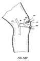
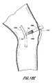
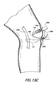
1つの方法では、この手順は、関節鏡検査法で行われる。一実施形態では、この手順は、非関節鏡検査法で行われる。一実施形態では、例えば、経皮的手法を使用することができる。一実施形態では、6mmのアンカを使用するが、異なるサイズおよび材料を使用することもできる。いくつかの例では、組織捕捉アンカが挿入される穴は、図15に示すように、ドリルビットまたは適当なサイズの突きぎりを使用して結節間溝1700の上部にアンカのためのクリアランスホールを形成することによって形成される。この穴は、腱の症状などに応じて、任意の他の適当な位置に形成することもできる。図15および図16は、肩の結節間溝および周囲の骨ならびに二頭筋の異なる見た目を示す図である。結節間溝(bicipital groove)は、二頭筋の長頭によって占められる上腕骨の上部にある溝であり、結節間溝(intertubercular groove)とも呼ばれる。いくつかの実施形態では、7mmのドリルビットを使用するが、他の実施形態では、異なるサイズのドリルビットを使用することもできる。一実施形態では、クリアランスホールは、幅を5mmから9mmにしてもよいし、6.5mmから8mmにしてもよいし、あるいは任意のその他の所望の範囲にしてもよい。クリアランスホールのサイズはアンカのサイズによって決まるので、他の実施形態では、クリアランスホールのサイズは変化することになる。骨の柔らかさおよびアンカのサイズに応じて、穴は、約21mm、約30mm、または任意のその他の所望の深さなど、8mm〜40mmの深さにすることができる。例えば、一実施形態では、6mmの組織捕捉アンカを使用し、柔らかい骨の場合には、穴の深さを少なくとも11mmにすることができる。平均的な骨の場合には、穴の深さは、約10〜12mmにすることができる。非常に柔らかい骨の場合には、穴の深さを約20mmにすることができる。
In one method, this procedure is performed with arthroscopy. In one embodiment, this procedure is performed with non-arthroscopy. In one embodiment, for example, a transdermal technique can be used. In one embodiment, a 6 mm anchor is used, but different sizes and materials can be used. In some examples, the hole into which the tissue capture anchor is inserted has a clearance hole for the anchor at the top of the
移植部位は、バーまたはその他の適当な手段を使用して骨の穴の領域に軟組織があれば除去する。アンカ本体110、410を挿入するときより取り除くときの方が抵抗を大きくする、角度のついた突起または歯を使用することができる。
The implantation site is removed if there is soft tissue in the area of the bone hole using a bar or other suitable means. Angled protrusions or teeth can be used that provide greater resistance when the
1つの非限定的な実施形態では、肩の準備は、参照によりその全体を本明細書に組み込む非特許文献1と同じにする。肩は、回旋腱板の高さまで軟組織切開を受ける。ここで、棘上筋腱挿入は、鋭い切開によって反転され、長頭二頭筋腱を検査して症状の証拠を探す。次いで、LHBの腱を鋭く切開し、関節窩の上面の関節内起始から解放し、かつ二頭筋腱が自由セグメントになるように筋腱結合部として分割する。他の実施形態では、肩を準備する他の方法が使用される。 In one non-limiting embodiment, the shoulder preparation is the same as in Non-Patent Document 1, which is hereby incorporated by reference in its entirety. The shoulder undergoes a soft tissue incision up to the level of the rotator cuff. Here, the supraspinatus tendon insertion is reversed by a sharp incision and the long biceps tendon is examined for evidence of symptoms. The LHB tendon is then sharply incised, released from the intra-articular origin on the upper surface of the glenoid and split as a muscle tendon joint so that the biceps tendon is a free segment. In other embodiments, other methods of preparing the shoulder are used.
いくつかの例示的な実施形態では、修復は、標準的なドリルビットを使用して結節間溝の上部にアンカのためのクリアランスホールを穿孔することによって完了する。次いで、腱を上述のアンカで捕捉し、クリアランスホールの中に押し込み、腱を捕捉するようにアンカを配置する。腱は、基本的には、アンカの周りで長手方向に折れることになるので、二面接触になる。アンカの近位表面は、皮質表面と面一になるように位置づけられる。いくつかの実施形態では、この穴は、骨の他の部分に位置することもできる。1つの例示的な実施形態では、この穴は、結節間溝の端部より約1cm遠位側に配置することができる。 In some exemplary embodiments, the repair is completed by drilling a clearance hole for the anchor at the top of the internodal groove using a standard drill bit. The tendon is then captured with the anchor described above, pushed into the clearance hole, and the anchor is positioned to capture the tendon. The tendon basically breaks in the longitudinal direction around the anchor, resulting in a two-sided contact. The proximal surface of the anchor is positioned to be flush with the cortical surface. In some embodiments, the hole may be located in other parts of the bone. In one exemplary embodiment, the hole can be located about 1 cm distal to the end of the internodal groove.
別の実施形態では、上述のアンカは、前十字靱帯(ACL)の修復に使用される。この実施形態では、大腿骨骨孔を骨に穿孔する。1つまたは2つの腱の束を、アンカで捕捉する。次いで、アンカを上述のように骨の中に挿入し、配備する。上述のように、腱は、様々な方法を用いて捕捉することができる。 In another embodiment, the anchor described above is used for repair of the anterior cruciate ligament (ACL). In this embodiment, a femoral bone hole is drilled into the bone. One or two tendon bundles are captured with an anchor. The anchor is then inserted into the bone and deployed as described above. As described above, tendons can be captured using a variety of methods.
一実施形態では、直径約9mmの孔を骨に穿孔する。アンカは、把持器具が腱を把持するように実装することができるように位置決めされる。次いで、腱を操作し、移動または位置決めする。一実施形態では、腱の二重束が大腿内の単一の骨トンネルに挿入される。一実施形態では、薄筋および半腱様筋腱は、両方とも骨の穴へ挿入するために折り曲げられる。一実施形態では約8mmまたは9mmの直径を有することがあるアンカは、これらの腱が折り曲げられている骨の穴へ挿入される。孔のサイズにより、8または9mmの直径を有することがあるアンカは、折り曲げられた腱がその先端を覆っている状態で穴に挿入される。アンカは、単束単骨孔(single bundle single tunnel)手順および単束二重骨孔(single bundle double tunnel)手順にも適している。他の実施形態では、骨の穴およびアンカは、必要に応じて異なるサイズにすることができる。 In one embodiment, a hole about 9 mm in diameter is drilled in the bone. The anchor is positioned so that the grasping instrument can be implemented to grasp the tendon. The tendon is then manipulated and moved or positioned. In one embodiment, a double bundle of tendons is inserted into a single bone tunnel in the thigh. In one embodiment, both the thin and semi-tendonous tendons are folded for insertion into the bone hole. Anchors, which may have a diameter of about 8 mm or 9 mm in one embodiment, are inserted into the bone holes where these tendons are folded. Anchors that may have a diameter of 8 or 9 mm, depending on the size of the hole, are inserted into the hole with the folded tendon covering its tip. Anchors are also suitable for single bundle single tunnel procedures and single bundle double tunnel procedures. In other embodiments, the bone holes and anchors can be sized differently as needed.
一実施形態では、執刀医は、大腿骨の中まで脛骨に穿孔し、アンカおよび腱をその脛骨骨孔を通るように載置する。一実施形態では、前内側ポータルを使用して、大腿骨骨孔と、別個の脛骨骨孔とに穿孔する。 In one embodiment, the surgeon punctures the tibia into the femur and places the anchor and tendon through the tibial tunnel. In one embodiment, an anterior medial portal is used to drill into a femoral bone hole and a separate tibial hole.
組織捕捉アンカ400および2500と挿入器具1000とが、腱または組織を骨に容易に取り付けるためのシステムを提供することは、当業者には理解されるであろう。アンカ400および2500は、周囲の組織の破壊を最小限にして、骨の中に挿入することができる。必要となるのは、外側管1200およびアンカ本体410の直径を有するアクセス経路だけである。さらに、アンカは、その部位に追加の機器を挿入する必要なく、または糸結びなどいかなる面倒な取付け操作も実行せずに、しっかりと骨に取り付けることができる。
Those skilled in the art will appreciate that the tissue capture anchors 400 and 2500 and the
別の実施形態では、上述のアンカは、例えば膝蓋大腿靱帯再建、後外側再建、およびACL手順の脛骨アンカバックアップなど、膝におけるその他の手順に使用される。 In another embodiment, the anchors described above are used for other procedures in the knee, such as patellofemoral ligament reconstruction, posterior lateral reconstruction, and tibial anchor backup for ACL procedures.
いくつかの実施形態では、上述のアンカは、足および足首の多数の組織固定手順に使用することができる。これらは、アキレス腱の機構を喪失した場合の長母指屈筋のアキレス腱への移植、下垂足の場合のブリドル/修正ブリドル手順とも呼ばれる後脛骨筋腱の前中足(中楔状骨)への移植、足首が不安定な場合の同種移植による外側靱帯再建(主にBrostrom−Gould手順を用いる場合もある)または分離した短腓骨筋を用いた非解剖学的な外側靱帯再建、(三角筋が不十分な場合の)同種移植による三角靱帯再建、ならびに再建不能な腓骨腱損傷の場合の長指屈筋または長母指屈筋の腓骨への移植、および長母指伸筋腱の移植による断裂した前脛骨筋の再建などを含む。 In some embodiments, the anchors described above can be used for a number of foot and ankle tissue fixation procedures. These include the implantation of the long flexor flexor to the Achilles tendon when the Achilles tendon mechanism is lost, the implantation of the posterior tibialis tendon to the anterior middle leg (medium cuneiform bone), also referred to as the bridle / modified bridle procedure for the foot drop, External ligament reconstruction by allograft when the ankle is unstable (mainly using the Brostrom-Gould procedure) or non-anatomical lateral ligament reconstruction using isolated short peroneal muscle (insufficient deltoid muscle) Reconstructed triangular ligament by allotransplantation, and fracture of anterior tibial muscle by transplantation of the long flexor or long flexor flexor to the rib in case of non-reconstructable radial tendon injury, and transplantation of the long thumb extensor tendon Including reconstruction.
400 デュアルエキスパンション骨アンカ
402 遠位端部
404 近位端部
410 アンカ本体
412 第1の端部
414 第2の端部
416 軸方向内腔
418 第1のタイン
420 第1の拡張スロット
422 第2のタイン
424 第2の拡張スロット
430 長手方向軸
432 第1の傾斜部分
434 第1の止め
436 第2の傾斜部分
438 平行部分
480 エキスパンダ
700 エキスパンダ
702 拡張部材
710 第1の端部
712 第2の端部
714 展開頭部
716 基部
718 シャフト
720 カム作用表面
750 エキスパンダ
757 縫合糸
788 ワイヤループ
800 シングルピースエキスパンダ
802 拡張部材
810 第1の端部
812 第2の端部
814 展開頭部
816 基部
818 第1のシャフト部分
820 展開ショルダ/カム作用表面
822 第2のシャフト部
850 アンカ
852 アンカ本体
854 第1の端部
856 第2の端部
858 軸方向内腔
860 第1のタイン
862 第1の拡張スロット
864 第2のタイン
868 第1の止め
870 カム作用当接部
900 ツーピースエキスパンダ
902 第1の拡張部材
904 第2の拡張部材
910 第1の端部
912 第2の端部
914 第1の展開頭部
916 基部
918 第1のシャフト部分
920 第1の端部
922 第2の端部
924 第2の展開頭部
926 基部
928 第2のシャフト部分
930 貫通孔
950 アンカ
952 アンカ本体
954 第1の端部
956 第2の端部
958 軸方向内腔
960 第1のタイン
962 第1の拡張スロット
964 第2のタイン
966 第2の拡張スロット
968 第1の止め
970 第2の止め
1000 挿入器具
1000a 挿入器具
1100 内側ロッド/内側管
1100a 内側ロッド/内側管
1105 遠位端部
1110 ねじ
1125 本体
1200 外側管
1200a 外側管
1210a 遠位端部
1212a 第1の当接部
1220 開口
1220a 開口
1225 ねじ
1225 ねじ
1250 近位端部
1250a 近位端部
1260a 第1の基部
1262a 第1の突出当接部
1270a 第2の基部
1272a 第2の突出当接部
1300 ハンドル本体
1300a ハンドル本体
1302 ハンドル部分
1304 蓋ピース
1312 ブレース受け開口
1315 平坦表面
1330 隆起部
1400 ねじ付きアクチュエータシャフト
1400a ねじ付きアクチュエータシャフト
1405 遠位端部
1420 近位端部
1425 第2のねじ部
1430 平坦領域
1450 クリート
1500 配備ノブ
1500a 配備ノブ
1505 ねじ
1510 中央穴
1530 溝
2500 アンカ
2502 第1の関節鏡検査口
2504 腱
2506 第2の関節鏡検査口
400 Dual expansion bone anchor 402 Distal end 404 Proximal end 410 Anchor body 412 First end 414 Second end 416 Axial lumen 418 First tine 420 First expansion slot 422 Second Tine 424 Second expansion slot 430 Longitudinal axis 432 First inclined portion 434 First stop 436 Second inclined portion 438 Parallel portion 480 Expander 700 Expander 702 Expansion member 710 First end 712 Second End 714 Deployment head 716 Base 718 Shaft 720 Cam action surface 750 Expander 757 Suture 788 Wire loop 800 Single piece expander 802 Expansion member 810 First end 812 Second end 814 Deployment head 816 Base 818 First shaft portion 820 Open shoulder / cam working surface 822 Second shaft portion 850 Anchor 852 Anchor body 854 First end 856 Second end 858 Axial lumen 860 First tine 862 First expansion slot 864 Second tine 868 First stop 870 Cam action contact portion 900 Two-piece expander 902 First expansion member 904 Second expansion member 910 First end 912 Second end 914 First deployment head 916 Base 918 First 1 shaft portion 920 first end 922 second end 924 second deployment head 926 base 928 second shaft portion 930 through-hole 950 anchor 952 anchor body 954 first end 956 second end Part 958 Axial lumen 960 First tine 962 First expansion slot 964 Second tine 966 Second expansion Slot 968 First stop 970 Second stop 1000 Insertion instrument 1000a Insertion instrument 1100 Inner rod / inner tube 1100a Inner rod / inner tube 1105 Distal end 1110 Screw 1125 Body 1200 Outer tube 1200a Outer tube 1210a Distal end 1212a First abutting portion 1220 Opening 1220a Opening 1225 Screw 1225 Screw 1250 Proximal end 1250a Proximal end 1260a First base 1262a First projecting contact 1270a Second base 1272a Second projecting contact 1300 Handle body 1300a Handle body 1302 Handle portion 1304 Cover piece 1312 Brace receiving opening 1315 Flat surface 1330 Raised portion 1400 Threaded actuator shaft 1400a Threaded actuator shaft 1405 distal end 1420 proximal end 1425 second thread 1430 flat region 1450 cleat 1500 deployment knob 1500a deployment knob 1505 screw 1510 central hole 1530 groove 2500 anchor 2502 first arthroscopy port 2504 tendon 2506 second Arthroscopy mouth
Claims (24)
少なくとも1つの拡張部分、および
エキスパンダの遠位端部の第1の開口を備えるエキスパンダであり、
前記アンカ本体に対する第1の位置と前記アンカ本体に対する第2の位置との間で変位可能であり、前記拡張部分が、前記エキスパンダが前記第2の位置にあるときに前記アンカ本体を拡張させるように構成されるエキスパンダと、
前記第1の開口を通って延びる引き込み可能な縫合糸グラバと、
を備えることを特徴とする骨アンカ。 An expandable anchor body,
An expander comprising at least one expansion portion and a first opening at the distal end of the expander;
Displaceable between a first position relative to the anchor body and a second position relative to the anchor body, and the expansion portion expands the anchor body when the expander is in the second position. An expander configured as
A retractable suture grabber extending through said first opening;
A bone anchor characterized by comprising:
前記骨アンカに結合された挿入器具とを備える、アンカ/挿入器アセンブリ。 A bone anchor according to claim 1;
An anchor / inserter assembly comprising an insertion instrument coupled to the bone anchor.
請求項1に記載の骨アンカを、第1の関節鏡検査口を通して患者に挿入するステップと、
前記縫合糸グラバを第2の関節鏡検査口を通して前記患者から引き出すステップと、
縫合糸を軟組織の周りに通すステップと、
前記縫合糸の少なくとも第1のリムを、前記第2の関節鏡検査口を通して前記患者から引き出すステップと、
前記縫合糸を前記縫合糸グラバと係合させるステップと、
前記縫合糸グラバを、前記エキスパンダの前記遠位端部の前記第1の開口を通して引き込むことにより、前記第1の開口を通して前記縫合糸の前記第1のリムを引っ張るステップと、
を含むことを特徴とする方法。 A method of fixing soft tissue to a bone anchor,
Inserting the bone anchor according to claim 1 into a patient through a first arthroscopic port;
Withdrawing the suture grabber from the patient through a second arthroscopic port;
Passing a suture around the soft tissue;
Withdrawing at least a first rim of the suture from the patient through the second arthroscopic port;
Engaging the suture with the suture grabber;
Pulling the first rim of the suture through the first opening by pulling the suture grabber through the first opening at the distal end of the expander;
A method comprising the steps of:
Applications Claiming Priority (3)
| Application Number | Priority Date | Filing Date | Title |
|---|---|---|---|
| US201361786168P | 2013-03-14 | 2013-03-14 | |
| US61/786,168 | 2013-03-14 | ||
| PCT/US2014/021774 WO2014159058A1 (en) | 2013-03-14 | 2014-03-07 | Tissue capturing bone anchor |
Related Child Applications (1)
| Application Number | Title | Priority Date | Filing Date |
|---|---|---|---|
| JP2018187747A Division JP6619493B2 (en) | 2013-03-14 | 2018-10-02 | Tissue capture bone anchor |
Publications (1)
| Publication Number | Publication Date |
|---|---|
| JP2016515005A true JP2016515005A (en) | 2016-05-26 |
Family
ID=51625100
Family Applications (3)
| Application Number | Title | Priority Date | Filing Date |
|---|---|---|---|
| JP2016500846A Pending JP2016515005A (en) | 2013-03-14 | 2014-03-07 | Tissue capture bone anchor |
| JP2018187747A Active JP6619493B2 (en) | 2013-03-14 | 2018-10-02 | Tissue capture bone anchor |
| JP2019206163A Active JP6874095B2 (en) | 2013-03-14 | 2019-11-14 | Tissue capture bone anchor |
Family Applications After (2)
| Application Number | Title | Priority Date | Filing Date |
|---|---|---|---|
| JP2018187747A Active JP6619493B2 (en) | 2013-03-14 | 2018-10-02 | Tissue capture bone anchor |
| JP2019206163A Active JP6874095B2 (en) | 2013-03-14 | 2019-11-14 | Tissue capture bone anchor |
Country Status (11)
| Country | Link |
|---|---|
| US (3) | US10149751B2 (en) |
| EP (1) | EP2967552B8 (en) |
| JP (3) | JP2016515005A (en) |
| KR (2) | KR102391275B1 (en) |
| AU (1) | AU2014241394B2 (en) |
| BR (1) | BR112015022457B1 (en) |
| CA (1) | CA2904702C (en) |
| ES (1) | ES2959496T3 (en) |
| MX (1) | MX366652B (en) |
| RU (1) | RU2015137618A (en) |
| WO (1) | WO2014159058A1 (en) |
Cited By (3)
| Publication number | Priority date | Publication date | Assignee | Title |
|---|---|---|---|---|
| JP2019536559A (en) * | 2016-11-30 | 2019-12-19 | アキュイティブ テクノロジーズ,インコーポレイティッド | Bioabsorbable deformable anchor |
| JP2020523109A (en) * | 2017-06-12 | 2020-08-06 | コンメッド コーポレーション | Expansion anchor |
| JP2021532941A (en) * | 2018-08-10 | 2021-12-02 | コンメッド コーポレーション | Tendon fixation device |
Families Citing this family (14)
| Publication number | Priority date | Publication date | Assignee | Title |
|---|---|---|---|---|
| US20160270902A1 (en) * | 2012-11-13 | 2016-09-22 | Universitat Zurich | Device for fixation of a flexible element, particularly a natural or synthetical ligament or tendon, to a bone |
| US10188379B2 (en) * | 2015-09-03 | 2019-01-29 | Ethicon Llc | End effector for wound closure device |
| EP3150153B1 (en) * | 2015-09-29 | 2019-10-30 | Orthofix S.r.l. | Endosseous screw assembly and internal fixation system comprising said endosseous screw assembly |
| CA3110987C (en) * | 2015-12-16 | 2023-08-22 | Conmed Corporation | Knotless suture anchor and deployment device |
| WO2017192214A1 (en) * | 2016-05-03 | 2017-11-09 | Smith & Nephew, Inc. | Expanding knotless suture anchor |
| WO2017205099A1 (en) * | 2016-05-24 | 2017-11-30 | Level 3 Communications, Llc | Route selection system for a communication network and method of operating the same |
| US10624734B2 (en) * | 2016-10-18 | 2020-04-21 | Arthrex, Inc. | Surgical assembly for tissue repair |
| US10631853B2 (en) * | 2017-10-06 | 2020-04-28 | Lsi Solutions, Inc. | Suture securing tube and assembly thereof |
| TWI689296B (en) * | 2018-12-07 | 2020-04-01 | 財團法人工業技術研究院 | Expansion ligament fastening apparatus |
| CN113194843A (en) * | 2018-12-18 | 2021-07-30 | 康曼德公司 | Self-drilling anchor inserter |
| IT201900001423A1 (en) * | 2019-01-31 | 2020-07-31 | Dangelo Fabio | SURGICAL FIXING ELEMENT |
| US11160546B2 (en) * | 2019-07-11 | 2021-11-02 | Arthrex, Inc. | Expanding implant and method of tissue fixation |
| WO2023044295A1 (en) * | 2021-09-14 | 2023-03-23 | Responsive Arthroscopy, LLC | Improved push-in suture anchor system |
| WO2024005720A1 (en) * | 2022-06-30 | 2024-01-04 | Tendonplus Medical Pte. Ltd. | A device for tissue repair, and a method of repairing a tissue using the device |
Citations (3)
| Publication number | Priority date | Publication date | Assignee | Title |
|---|---|---|---|---|
| US20100198258A1 (en) * | 2009-01-30 | 2010-08-05 | Kfx Medical Corporation | System and method for attaching soft tissue to bone |
| US20100292732A1 (en) * | 2009-05-12 | 2010-11-18 | Foundry Newco Xi, Inc. | Suture anchors with one-way cinching mechanisms |
| WO2012148693A1 (en) * | 2011-04-13 | 2012-11-01 | Kfx Medical Corporation | System and method for securing tissue to bone |
Family Cites Families (185)
| Publication number | Priority date | Publication date | Assignee | Title |
|---|---|---|---|---|
| US605763A (en) | 1898-06-14 | Triangle | ||
| US37963A (en) | 1863-03-24 | Improvement in grain-screens | ||
| US36289A (en) | 1862-08-26 | Improvement in pipe-wrenches | ||
| CH648197A5 (en) * | 1980-05-28 | 1985-03-15 | Synthes Ag | IMPLANT AND SCREW FASTENING ON ITS BONE. |
| GB2084468B (en) | 1980-09-25 | 1984-06-06 | South African Inventions | Surgical implant |
| US5417691A (en) | 1982-05-20 | 1995-05-23 | Hayhurst; John O. | Apparatus and method for manipulating and anchoring tissue |
| US5601557A (en) | 1982-05-20 | 1997-02-11 | Hayhurst; John O. | Anchoring and manipulating tissue |
| IL70736A (en) | 1984-01-20 | 1988-05-31 | Rosenberg Lior | Self-locking pin device particularly useful for internally fixing bone fractures |
| US4738255A (en) | 1986-04-07 | 1988-04-19 | Biotron Labs, Inc. | Suture anchor system |
| EP0270704B1 (en) | 1986-12-12 | 1989-04-26 | Aesculap Ag | Anchoring element for fastening an osteosynthesis plate to a bone |
| WO1997007741A1 (en) | 1995-08-24 | 1997-03-06 | Inbae Yoon | Suture tie device system and method for suturing anatomical tissue proximate an opening |
| US4898156A (en) | 1987-05-18 | 1990-02-06 | Mitek Surgical Products, Inc. | Suture anchor |
| US5197983A (en) | 1988-04-19 | 1993-03-30 | W. L. Gore & Associates, Inc. | Ligament and tendon prosthesis |
| US4960420A (en) | 1988-08-23 | 1990-10-02 | Marlowe Goble E | Channel ligament clamp and system |
| US4870957A (en) | 1988-12-27 | 1989-10-03 | Marlowe Goble E | Ligament anchor system |
| US4988351A (en) | 1989-01-06 | 1991-01-29 | Concept, Inc. | Washer for use with cancellous screw for attaching soft tissue to bone |
| DE3923411A1 (en) | 1989-07-13 | 1991-01-24 | Mecron Med Prod Gmbh | CONNECTING ELEMENT FOR OSTEOSYNTHESIS |
| GB8924806D0 (en) | 1989-11-03 | 1989-12-20 | Neoligaments Ltd | Prosthectic ligament system |
| US6464713B2 (en) | 1990-06-28 | 2002-10-15 | Peter M. Bonutti | Body tissue fastening |
| US6203565B1 (en) | 1990-06-28 | 2001-03-20 | Peter M. Bonutti | Surgical devices assembled using heat bondable materials |
| US5224946A (en) | 1990-07-02 | 1993-07-06 | American Cyanamid Company | Bone anchor and method of anchoring a suture to a bone |
| US5037422A (en) | 1990-07-02 | 1991-08-06 | Acufex Microsurgical, Inc. | Bone anchor and method of anchoring a suture to a bone |
| US5725529A (en) | 1990-09-25 | 1998-03-10 | Innovasive Devices, Inc. | Bone fastener |
| DE69130681T2 (en) | 1990-09-25 | 1999-06-10 | Innovasive Devices Inc | BONE FIXING DEVICE |
| FR2668361A1 (en) | 1990-10-30 | 1992-04-30 | Mai Christian | OSTEOSYNTHESIS CLIP AND PLATE WITH SELF-RETENTIVE DYNAMIC COMPRESSION. |
| US5222963A (en) | 1991-01-17 | 1993-06-29 | Ethicon, Inc. | Pull-through circular anastomosic intraluminal stapler with absorbable fastener means |
| FR2671717A1 (en) | 1991-01-17 | 1992-07-24 | Asa Laboratoires Prothaid | Expansion bolt for the fixation of a ligament prosthesis on the cortical wall of a bone |
| DE4106823C1 (en) | 1991-03-04 | 1992-06-25 | Liebscher Kunststofftechnik, 8032 Graefelfing, De | |
| US5354298A (en) | 1991-03-22 | 1994-10-11 | United States Surgical Corporation | Suture anchor installation system |
| US5720753A (en) | 1991-03-22 | 1998-02-24 | United States Surgical Corporation | Orthopedic fastener |
| US5480403A (en) | 1991-03-22 | 1996-01-02 | United States Surgical Corporation | Suture anchoring device and method |
| CA2063159C (en) | 1991-03-22 | 1999-06-15 | Thomas W. Sander | Orthopedic fastener |
| US5161916A (en) | 1991-06-03 | 1992-11-10 | White Claude C | Self-seating expansion anchor |
| US5167665A (en) | 1991-12-31 | 1992-12-01 | Mckinney William W | Method of attaching objects to bone |
| US5326205A (en) | 1992-05-27 | 1994-07-05 | Anspach Jr William E | Expandable rivet assembly |
| US5501695A (en) | 1992-05-27 | 1996-03-26 | The Anspach Effort, Inc. | Fastener for attaching objects to bones |
| US5176682A (en) | 1992-06-01 | 1993-01-05 | Chow James C Y | Surgical implement |
| CA2094111C (en) | 1992-06-15 | 1999-02-16 | Daniel R. Lee | Suture anchoring device and method |
| US5397356A (en) | 1993-01-15 | 1995-03-14 | Depuy Inc. | Pin for securing a replacement ligament to a bone |
| US5380334A (en) | 1993-02-17 | 1995-01-10 | Smith & Nephew Dyonics, Inc. | Soft tissue anchors and systems for implantation |
| US5372599A (en) | 1993-03-12 | 1994-12-13 | Mitek Surgical Products, Inc. | Surgical anchor and method for deploying the same |
| US5549630A (en) | 1993-05-14 | 1996-08-27 | Bonutti; Peter M. | Method and apparatus for anchoring a suture |
| US5403348A (en) | 1993-05-14 | 1995-04-04 | Bonutti; Peter M. | Suture anchor |
| US5505735A (en) | 1993-06-10 | 1996-04-09 | Mitek Surgical Products, Inc. | Surgical anchor and method for using the same |
| US5632748A (en) | 1993-06-14 | 1997-05-27 | Linvatec Corporation | Endosteal anchoring device for urging a ligament against a bone surface |
| US5372604A (en) | 1993-06-18 | 1994-12-13 | Linvatec Corporation | Suture anchor for soft tissue fixation |
| CA2124996C (en) | 1993-06-21 | 2006-01-31 | Thomas W. Sander | Orthopedic fastener applicator |
| US5522844A (en) | 1993-06-22 | 1996-06-04 | Johnson; Lanny L. | Suture anchor, suture anchor installation device and method for attaching a suture to a bone |
| US5722981A (en) * | 1993-10-08 | 1998-03-03 | Tahoe Surgical Instruments | Double needle ligature device |
| US5618314A (en) | 1993-12-13 | 1997-04-08 | Harwin; Steven F. | Suture anchor device |
| USRE36289E (en) | 1993-12-13 | 1999-08-31 | Ethicon, Inc. | Umbrella shaped suture anchor device with actuating ring member |
| US5545180A (en) | 1993-12-13 | 1996-08-13 | Ethicon, Inc. | Umbrella-shaped suture anchor device with actuating ring member |
| US5417712A (en) | 1994-02-17 | 1995-05-23 | Mitek Surgical Products, Inc. | Bone anchor |
| US5486197A (en) | 1994-03-24 | 1996-01-23 | Ethicon, Inc. | Two-piece suture anchor with barbs |
| US5562688A (en) * | 1994-03-25 | 1996-10-08 | Riza; Erol D. | Apparatus facilitating suturing in laparoscopic surgery |
| FR2718012A1 (en) | 1994-03-30 | 1995-10-06 | T2C Sarl | Intra-bone anchoring. |
| US5645589A (en) | 1994-08-22 | 1997-07-08 | Li Medical Technologies, Inc. | Anchor and method for securement into a bore |
| US5843127A (en) | 1994-08-22 | 1998-12-01 | Le Medical Technologies, Inc. | Fixation device and method for installing same |
| US5472452A (en) | 1994-08-30 | 1995-12-05 | Linvatec Corporation | Rectilinear anchor for soft tissue fixation |
| US5522845A (en) | 1994-09-27 | 1996-06-04 | Mitek Surgical Products, Inc. | Bone anchor and bone anchor installation |
| US5464427A (en) | 1994-10-04 | 1995-11-07 | Synthes (U.S.A.) | Expanding suture anchor |
| US5649963A (en) | 1994-11-10 | 1997-07-22 | Innovasive Devices, Inc. | Suture anchor assembly and methods |
| US5814071A (en) | 1994-11-10 | 1998-09-29 | Innovasive Devices, Inc. | Suture anchor assembly and methods |
| US5643321A (en) | 1994-11-10 | 1997-07-01 | Innovasive Devices | Suture anchor assembly and methods |
| US5643266A (en) | 1995-06-05 | 1997-07-01 | Li Medical Technologies, Inc. | Method and apparatus for securing ligaments |
| US5702215A (en) | 1995-06-05 | 1997-12-30 | Li Medical Technologies, Inc. | Retractable fixation device |
| US5569306A (en) | 1995-06-06 | 1996-10-29 | Thal; Raymond | Knotless suture anchor assembly |
| CA2219089C (en) | 1995-06-06 | 2001-05-08 | Raymond Thal | Knotless suture anchor assembly |
| EP0955894A4 (en) | 1995-08-25 | 2001-02-28 | R Thomas Grotz | Stabilizer for human joints |
| US5681333A (en) * | 1995-11-08 | 1997-10-28 | Arthrex, Inc. | Method and apparatus for arthroscopic rotator cuff repair utilizing bone tunnels for suture attachment |
| US5690649A (en) | 1995-12-05 | 1997-11-25 | Li Medical Technologies, Inc. | Anchor and anchor installation tool and method |
| US5741282A (en) | 1996-01-22 | 1998-04-21 | The Anspach Effort, Inc. | Soft tissue fastener device |
| US5957953A (en) | 1996-02-16 | 1999-09-28 | Smith & Nephew, Inc. | Expandable suture anchor |
| US5849004A (en) | 1996-07-17 | 1998-12-15 | Bramlet; Dale G. | Surgical anchor |
| US5718717A (en) | 1996-08-19 | 1998-02-17 | Bonutti; Peter M. | Suture anchor |
| US5741300A (en) | 1996-09-10 | 1998-04-21 | Li Medical Technologies, Inc. | Surgical anchor and package and cartridge for surgical anchor |
| US7611521B2 (en) | 1996-09-13 | 2009-11-03 | Tendon Technology, Ltd. | Apparatus and methods for tendon or ligament repair |
| US5948000A (en) | 1996-10-03 | 1999-09-07 | United States Surgical Corporation | System for suture anchor placement |
| US6648890B2 (en) | 1996-11-12 | 2003-11-18 | Triage Medical, Inc. | Bone fixation system with radially extendable anchor |
| US6632224B2 (en) | 1996-11-12 | 2003-10-14 | Triage Medical, Inc. | Bone fixation system |
| US5948002A (en) | 1996-11-15 | 1999-09-07 | Bonutti; Peter M. | Apparatus and method for use in positioning a suture anchor |
| US5814072A (en) | 1996-11-15 | 1998-09-29 | Bonutti; Peter M. | Method and apparatus for use in anchoring a suture |
| EP1419747B1 (en) | 1996-11-21 | 2015-04-01 | Ethicon, Inc. | Apparatus for anchoring autologous or artificial tendon grafts in bone. |
| US6554862B2 (en) | 1996-11-27 | 2003-04-29 | Ethicon, Inc. | Graft ligament anchor and method for attaching a graft ligament to a bone |
| DE19731298A1 (en) | 1996-12-30 | 1999-11-18 | Basheir Madhoon | Nail system for intramedullar osteosynthesis of fractures and total end prostheses |
| US20080039859A1 (en) | 1997-01-02 | 2008-02-14 | Zucherman James F | Spine distraction implant and method |
| US5707395A (en) | 1997-01-16 | 1998-01-13 | Li Medical Technologies, Inc. | Surgical fastener and method and apparatus for ligament repair |
| US5709708A (en) | 1997-01-31 | 1998-01-20 | Thal; Raymond | Captured-loop knotless suture anchor assembly |
| US5782866A (en) | 1997-03-25 | 1998-07-21 | Ethicon, Inc. | System for anchoring tissue to bone |
| US5980558A (en) | 1997-09-30 | 1999-11-09 | Biomet Inc. | Suture anchor system |
| US6149669A (en) | 1997-10-30 | 2000-11-21 | Li Medical Technologies, Inc. | Surgical fastener assembly method of use |
| US6146406A (en) | 1998-02-12 | 2000-11-14 | Smith & Nephew, Inc. | Bone anchor |
| US6024758A (en) | 1998-02-23 | 2000-02-15 | Thal; Raymond | Two-part captured-loop knotless suture anchor assembly |
| US5964764A (en) | 1998-03-24 | 1999-10-12 | Hugh S. West, Jr. | Apparatus and methods for mounting a ligament graft to a bone |
| FR2777447B1 (en) | 1998-04-21 | 2000-07-28 | Tornier Sa | REVERSIBLE FIXATION DEVICE FOR PLACING AN IMPLANT IN THE BONE |
| FR2777442B1 (en) | 1998-04-21 | 2000-07-28 | Tornier Sa | REVERSIBLE EXPANSION SUTURE ANCHOR |
| US6063037A (en) | 1998-08-21 | 2000-05-16 | Manan Medical Products, Inc. | Bone marrow biopsy needle |
| ATE304817T1 (en) | 1998-10-26 | 2005-10-15 | Expanding Orthopedics Inc | EXPANDABLE ORTHOPEDIC DEVICE |
| US6846313B1 (en) | 1998-11-03 | 2005-01-25 | Codman & Shurtleff, Inc. | One-piece biocompatible absorbable rivet and pin for use in surgical procedures |
| US6241732B1 (en) | 1998-11-03 | 2001-06-05 | David W. Overaker | Biocompatible absorbable rivets and pins for use in surgical procedures |
| US6086591A (en) | 1999-01-29 | 2000-07-11 | Smith & Nephew, Inc. | Soft tissue anchor |
| US7226469B2 (en) | 1999-02-02 | 2007-06-05 | Arthrex, Inc. | Insert molded suture anchor |
| US6660022B1 (en) | 1999-06-01 | 2003-12-09 | Smith & Nephew, Inc. | Rotor blade anchor and tool for installing same |
| US6592609B1 (en) | 1999-08-09 | 2003-07-15 | Bonutti 2003 Trust-A | Method and apparatus for securing tissue |
| US6527794B1 (en) | 1999-08-10 | 2003-03-04 | Ethicon, Inc. | Self-locking suture anchor |
| US6635073B2 (en) | 2000-05-03 | 2003-10-21 | Peter M. Bonutti | Method of securing body tissue |
| US6287324B1 (en) | 2000-01-28 | 2001-09-11 | Shoulderon Ltd. | Self-drilling surgical suture anchor |
| US6673094B1 (en) | 2000-02-23 | 2004-01-06 | Ethicon, Inc. | System and method for attaching soft tissue to bone |
| US7993368B2 (en) | 2003-03-13 | 2011-08-09 | C.R. Bard, Inc. | Suture clips, delivery devices and methods |
| US6746483B1 (en) | 2000-03-16 | 2004-06-08 | Smith & Nephew, Inc. | Sheaths for implantable fixation devices |
| ATE338519T1 (en) | 2000-06-14 | 2006-09-15 | Teppo Jaervinen | FIXATION ANCHORS |
| WO2001097677A2 (en) | 2000-06-22 | 2001-12-27 | Arthrex, Inc. | Graft fixation using a screw or plug against suture or tissue |
| US7329272B2 (en) | 2000-06-22 | 2008-02-12 | Arthrex, Inc. | Graft fixation using a plug against suture |
| US6582453B1 (en) | 2000-07-14 | 2003-06-24 | Opus Medical, Inc. | Method and apparatus for attaching connective tissues to bone using a suture anchoring device |
| US6562044B1 (en) | 2000-08-21 | 2003-05-13 | Daniel E. Cooper | Soft tissue fixation device |
| US6585730B1 (en) | 2000-08-30 | 2003-07-01 | Opus Medical, Inc. | Method and apparatus for attaching connective tissues to bone using a knotless suture anchoring device |
| US7037324B2 (en) | 2000-09-15 | 2006-05-02 | United States Surgical Corporation | Knotless tissue anchor |
| US6652561B1 (en) | 2000-10-13 | 2003-11-25 | Opus Medical, Inc | Method and apparatus for attaching connective tissues to bone using a perforated suture anchoring device |
| EP1326557A2 (en) | 2000-10-17 | 2003-07-16 | Coapt Systems, Inc. | Intraosseous soft tissue-to-bone anchor |
| US6641596B1 (en) | 2000-10-18 | 2003-11-04 | Ethicon, Inc. | Knotless bioabsorbable suture anchor system and method |
| US6692516B2 (en) | 2000-11-28 | 2004-02-17 | Linvatec Corporation | Knotless suture anchor and method for knotlessly securing tissue |
| CA2432216C (en) | 2000-12-22 | 2009-03-10 | Jonathan Martinek | Suture screw |
| US6770076B2 (en) | 2001-02-12 | 2004-08-03 | Opus Medical, Inc. | Method and apparatus for attaching connective tissues to bone using a knotless suture anchoring device |
| US7144413B2 (en) | 2001-04-20 | 2006-12-05 | Synthes (U.S.A.) | Graft fixation system and method |
| US6641597B2 (en) | 2001-05-25 | 2003-11-04 | Arthrex, Inc. | Interference fit knotless suture anchor fixation |
| US6547800B2 (en) | 2001-06-06 | 2003-04-15 | Opus Medical, Inc. | Method and apparatus for attaching connective tissues to bone using a cortical bone anchoring device |
| US6887271B2 (en) | 2001-09-28 | 2005-05-03 | Ethicon, Inc. | Expanding ligament graft fixation system and method |
| US6712849B2 (en) | 2001-10-01 | 2004-03-30 | Scandius Biomedical, Inc. | Apparatus and method for reconstructing a ligament |
| US7520898B2 (en) | 2001-10-01 | 2009-04-21 | Scandius Biomedical, Inc. | Apparatus and method for reconstructing a ligament |
| US6656183B2 (en) | 2001-11-08 | 2003-12-02 | Smith & Nephew, Inc. | Tissue repair system |
| US6689135B2 (en) | 2002-01-25 | 2004-02-10 | Albert Enayati | Expandable bone fastener and installation tool |
| US7201754B2 (en) | 2002-02-08 | 2007-04-10 | Kenneth Stewart | Device for installing an anchor in a bone |
| EP1478283B1 (en) | 2002-02-25 | 2010-07-14 | Jeffrey E. Yeung | Expandable fastener with compressive grips |
| US6890354B2 (en) | 2002-03-08 | 2005-05-10 | Musculoskeletal Transplant Foundation | Bone-tendon-bone assembly with allograft bone block and method for inserting same |
| US6942666B2 (en) | 2002-03-29 | 2005-09-13 | Ethicon, Inc. | Expandable cable anchor |
| US20040230194A1 (en) | 2002-06-12 | 2004-11-18 | Urbanski Mark G. | Device and method for attaching soft tissue to bone |
| US20030233095A1 (en) | 2002-06-12 | 2003-12-18 | Urbanski Mark G. | Device and method for attaching soft tissue to bone |
| US6932834B2 (en) | 2002-06-27 | 2005-08-23 | Ethicon, Inc. | Suture anchor |
| US20040138683A1 (en) | 2003-01-09 | 2004-07-15 | Walter Shelton | Suture arrow device and method of using |
| US7588586B2 (en) | 2003-05-27 | 2009-09-15 | Ethicon, Inc. | Tissue fixation device |
| US7309355B2 (en) | 2003-06-27 | 2007-12-18 | Depuy Mitek, Inc. | Flexible tibial sheath |
| US7713285B1 (en) | 2003-07-02 | 2010-05-11 | Biomet Sports Medicine, Llc | Method and apparatus for suture anchors with a vertical eyelet |
| WO2005016123A2 (en) | 2003-08-11 | 2005-02-24 | Chudik Steven C M D | Devices and methods used for shoulder replacement |
| CA2552727A1 (en) | 2004-01-16 | 2005-08-04 | Expanding Orthopedics, Inc. | Bone fracture treatment devices |
| DK1820462T3 (en) | 2004-03-31 | 2011-12-19 | Orthofix Srl | Marrow stitching comprising elements of shape memory material |
| US20060282081A1 (en) | 2004-04-16 | 2006-12-14 | Fanton Gary S | Apparatus and method for securing tissue to bone with a suture |
| US8062334B2 (en) | 2004-06-02 | 2011-11-22 | Kfx Medical Corporation | Suture anchor |
| US7144415B2 (en) | 2004-11-16 | 2006-12-05 | The Anspach Effort, Inc. | Anchor/suture used for medical procedures |
| AU2005306450B9 (en) | 2004-11-18 | 2012-02-02 | Cayenne Medical, Inc. | Devices, systems and methods for material fixation |
| US8986345B2 (en) | 2004-12-07 | 2015-03-24 | Biomet Sports Medicine, Llc | Expanding suture anchor having an actuator pin |
| US7572283B1 (en) | 2004-12-07 | 2009-08-11 | Biomet Sports Medicine, Llc | Soft tissue rivet and method of use |
| US20060229617A1 (en) | 2005-02-25 | 2006-10-12 | Orthomechanics Ltd. | Intramedullary devices and methods of deploying the same |
| ES2300967T3 (en) | 2005-03-11 | 2008-06-16 | Orthofix S.R.L. | DEVICE FOR OSTEOSYNTHESIS OF PROXIMAL FRACTURES OF THE HUMER. |
| US20090187216A1 (en) | 2006-05-18 | 2009-07-23 | Arthrex, Inc. | Fenestrated swivel anchor for knotless fixation of tissue |
| US20060264951A1 (en) | 2005-05-18 | 2006-11-23 | Nelson Charles L | Minimally Invasive Actuable Bone Fixation Devices Having a Retractable Interdigitation Process |
| US7766946B2 (en) * | 2005-07-27 | 2010-08-03 | Frank Emile Bailly | Device for securing spinal rods |
| US20080221624A1 (en) | 2005-10-17 | 2008-09-11 | Gooch Hubert L | Systems and Methods for the Medical Treatment of Structural Tissue |
| FR2893836B1 (en) | 2005-11-29 | 2008-10-10 | Pierre Imbert | SURGICAL IMPLANT WITH EXTRA CORTICAL SUPPORT FOR LIGAMENTARY TRANSPLANT |
| DE602006002105D1 (en) | 2006-02-23 | 2008-09-18 | Biedermann Motech Gmbh | Bone anchoring device |
| EP2001405B1 (en) | 2006-03-20 | 2015-11-18 | Cayenne Medical, Inc. | Systems for tendon fixation |
| US20090043342A1 (en) | 2006-03-28 | 2009-02-12 | Yosef Freedland | Flat Shaft Fasteners |
| WO2008073588A2 (en) | 2006-10-24 | 2008-06-19 | Cayenne Medical, Inc. | Methods and systems for material fixation |
| US8221479B2 (en) | 2007-01-19 | 2012-07-17 | Pbj, Llc | Orthopedic screw insert |
| US20080195221A1 (en) | 2007-01-22 | 2008-08-14 | Zimmer Gmbh | Implant and a method for partial replacement of joint surfaces |
| US20090036905A1 (en) | 2007-01-30 | 2009-02-05 | Reinhold Schmieding | Method of tissue fixation using cinch stitching |
| GB0710023D0 (en) | 2007-05-25 | 2007-07-04 | Facilities Council | Graft fixation device |
| US20090149884A1 (en) | 2007-08-02 | 2009-06-11 | Redyns Medical, Llc | System and method for bridge anchor tendon attachment |
| US8162978B2 (en) * | 2008-03-25 | 2012-04-24 | Linvatec Corporation | Non-metallic knotless suture anchor |
| US9351778B2 (en) | 2008-06-20 | 2016-05-31 | Yale University | Porous expansion bolt |
| US8069858B2 (en) | 2008-07-24 | 2011-12-06 | Medshape Solutions, Inc. | Method and apparatus for deploying a shape memory polymer |
| US8430933B2 (en) | 2008-07-24 | 2013-04-30 | MedShape Inc. | Method and apparatus for deploying a shape memory polymer |
| EP2323543A1 (en) | 2008-08-05 | 2011-05-25 | PH Diagnostics Inc. | Apparatus, method and system for determining a physiological condition within a mammal |
| US20110190815A1 (en) * | 2008-09-08 | 2011-08-04 | Saliman Justin D | Knotless suture anchors |
| CA2738478A1 (en) | 2008-09-26 | 2010-04-01 | Sonoma Orthopedic Products, Inc. | Bone fixation device, tools and methods |
| USD605763S1 (en) | 2009-01-02 | 2009-12-08 | Medshape Solutions, Inc. | Suture anchor device |
| DE102009051367B4 (en) * | 2009-04-28 | 2016-07-28 | Mathys Ag Bettlach | Implantable system with continuous dissolution mechanism during healing |
| US8906060B2 (en) | 2009-06-24 | 2014-12-09 | Karl Storz Gmbh & Co. Kg | Method and apparatus for soft tissue fixation to bone |
| EP2488118B1 (en) | 2009-10-13 | 2022-01-05 | ConMed Corporation | System for securing tissue to bone |
| US9044313B2 (en) | 2010-10-08 | 2015-06-02 | Kfx Medical Corporation | System and method for securing tissue to bone |
| IT1403113B1 (en) * | 2010-10-22 | 2013-10-04 | Ncs Lab S R L | FIXING DEVICE FOR SUTURE WIRES TO BE INSERTED IN BONE FABRIC. |
| WO2012093961A1 (en) | 2011-01-05 | 2012-07-12 | Milux Holding S.A. | Knee joint device |
| US9107653B2 (en) * | 2011-09-22 | 2015-08-18 | Arthrex, Inc. | Tensionable knotless anchors with splice and methods of tissue repair |
| EP2763598B1 (en) * | 2011-10-04 | 2020-12-02 | ConMed Corporation | Dual expansion anchor |
| US10076377B2 (en) * | 2013-01-05 | 2018-09-18 | P Tech, Llc | Fixation systems and methods |
| EP3060167B1 (en) | 2013-10-25 | 2022-05-04 | Kyon AG | Holding and adjustment mechanism for surgical tether |
-
2014
- 2014-03-07 ES ES14773767T patent/ES2959496T3/en active Active
- 2014-03-07 WO PCT/US2014/021774 patent/WO2014159058A1/en active Application Filing
- 2014-03-07 MX MX2015011510A patent/MX366652B/en active IP Right Grant
- 2014-03-07 KR KR1020217015249A patent/KR102391275B1/en active IP Right Grant
- 2014-03-07 EP EP14773767.0A patent/EP2967552B8/en active Active
- 2014-03-07 US US14/774,675 patent/US10149751B2/en active Active
- 2014-03-07 JP JP2016500846A patent/JP2016515005A/en active Pending
- 2014-03-07 RU RU2015137618A patent/RU2015137618A/en not_active Application Discontinuation
- 2014-03-07 CA CA2904702A patent/CA2904702C/en active Active
- 2014-03-07 BR BR112015022457-1A patent/BR112015022457B1/en active IP Right Grant
- 2014-03-07 AU AU2014241394A patent/AU2014241394B2/en active Active
- 2014-03-07 KR KR1020157028500A patent/KR102257312B1/en active IP Right Grant
-
2018
- 2018-10-02 JP JP2018187747A patent/JP6619493B2/en active Active
- 2018-11-26 US US16/199,660 patent/US11020218B2/en active Active
-
2019
- 2019-11-14 JP JP2019206163A patent/JP6874095B2/en active Active
-
2021
- 2021-06-01 US US17/335,682 patent/US20210282918A1/en active Pending
Patent Citations (3)
| Publication number | Priority date | Publication date | Assignee | Title |
|---|---|---|---|---|
| US20100198258A1 (en) * | 2009-01-30 | 2010-08-05 | Kfx Medical Corporation | System and method for attaching soft tissue to bone |
| US20100292732A1 (en) * | 2009-05-12 | 2010-11-18 | Foundry Newco Xi, Inc. | Suture anchors with one-way cinching mechanisms |
| WO2012148693A1 (en) * | 2011-04-13 | 2012-11-01 | Kfx Medical Corporation | System and method for securing tissue to bone |
Cited By (6)
| Publication number | Priority date | Publication date | Assignee | Title |
|---|---|---|---|---|
| JP2019536559A (en) * | 2016-11-30 | 2019-12-19 | アキュイティブ テクノロジーズ,インコーポレイティッド | Bioabsorbable deformable anchor |
| JP7071358B2 (en) | 2016-11-30 | 2022-05-18 | アキュイティブ テクノロジーズ,インコーポレイティッド | Bioabsorbable deformable anchor |
| JP2020523109A (en) * | 2017-06-12 | 2020-08-06 | コンメッド コーポレーション | Expansion anchor |
| JP6998973B2 (en) | 2017-06-12 | 2022-01-18 | コンメッド コーポレーション | Expansion anchor |
| JP2021532941A (en) * | 2018-08-10 | 2021-12-02 | コンメッド コーポレーション | Tendon fixation device |
| JP7293335B2 (en) | 2018-08-10 | 2023-06-19 | コンメッド コーポレーション | Tendon fixation device |
Also Published As
| Publication number | Publication date |
|---|---|
| JP2020039890A (en) | 2020-03-19 |
| ES2959496T3 (en) | 2024-02-26 |
| US11020218B2 (en) | 2021-06-01 |
| EP2967552B1 (en) | 2023-07-26 |
| KR102257312B1 (en) | 2021-05-28 |
| KR102391275B1 (en) | 2022-04-27 |
| AU2014241394A1 (en) | 2015-10-01 |
| MX366652B (en) | 2019-07-17 |
| WO2014159058A1 (en) | 2014-10-02 |
| EP2967552A4 (en) | 2016-11-23 |
| BR112015022457B1 (en) | 2022-03-15 |
| CA2904702C (en) | 2020-01-07 |
| RU2015137618A (en) | 2017-04-18 |
| EP2967552A1 (en) | 2016-01-20 |
| JP6619493B2 (en) | 2019-12-11 |
| US20190117377A1 (en) | 2019-04-25 |
| AU2014241394B2 (en) | 2018-10-18 |
| US20210282918A1 (en) | 2021-09-16 |
| JP2019022713A (en) | 2019-02-14 |
| KR20150126680A (en) | 2015-11-12 |
| EP2967552B8 (en) | 2023-08-30 |
| US10149751B2 (en) | 2018-12-11 |
| KR20210063436A (en) | 2021-06-01 |
| BR112015022457A2 (en) | 2017-07-18 |
| CA2904702A1 (en) | 2014-10-02 |
| US20160030159A1 (en) | 2016-02-04 |
| JP6874095B2 (en) | 2021-05-19 |
| MX2015011510A (en) | 2016-06-14 |
Similar Documents
| Publication | Publication Date | Title |
|---|---|---|
| JP6619493B2 (en) | Tissue capture bone anchor | |
| AU2019216718B2 (en) | Dual expansion anchor | |
| US20220395268A1 (en) | System and method for securing tissue to bone | |
| JP6776402B2 (en) | Systems and methods for fixing tissue to bone | |
| US20150039030A1 (en) | Transosteal anchoring methods for tissue repair |
Legal Events
| Date | Code | Title | Description |
|---|---|---|---|
| A621 | Written request for application examination |
Free format text: JAPANESE INTERMEDIATE CODE: A621 Effective date: 20170113 |
|
| A711 | Notification of change in applicant |
Free format text: JAPANESE INTERMEDIATE CODE: A711 Effective date: 20170222 |
|
| A521 | Request for written amendment filed |
Free format text: JAPANESE INTERMEDIATE CODE: A821 Effective date: 20170222 |
|
| A977 | Report on retrieval |
Free format text: JAPANESE INTERMEDIATE CODE: A971007 Effective date: 20171012 |
|
| A131 | Notification of reasons for refusal |
Free format text: JAPANESE INTERMEDIATE CODE: A131 Effective date: 20171017 |
|
| A601 | Written request for extension of time |
Free format text: JAPANESE INTERMEDIATE CODE: A601 Effective date: 20180116 |
|
| A521 | Request for written amendment filed |
Free format text: JAPANESE INTERMEDIATE CODE: A523 Effective date: 20180319 |
|
| A02 | Decision of refusal |
Free format text: JAPANESE INTERMEDIATE CODE: A02 Effective date: 20180605 |