JP2016514009A - Electrosurgical device with a disposable shaft having a translating gear and snap fit - Google Patents
Electrosurgical device with a disposable shaft having a translating gear and snap fit Download PDFInfo
- Publication number
- JP2016514009A JP2016514009A JP2016500258A JP2016500258A JP2016514009A JP 2016514009 A JP2016514009 A JP 2016514009A JP 2016500258 A JP2016500258 A JP 2016500258A JP 2016500258 A JP2016500258 A JP 2016500258A JP 2016514009 A JP2016514009 A JP 2016514009A
- Authority
- JP
- Japan
- Prior art keywords
- assembly
- shaft
- drive
- interface
- instrument
- Prior art date
- Legal status (The legal status is an assumption and is not a legal conclusion. Google has not performed a legal analysis and makes no representation as to the accuracy of the status listed.)
- Granted
Links
Images


Classifications
-
- A—HUMAN NECESSITIES
- A61—MEDICAL OR VETERINARY SCIENCE; HYGIENE
- A61B—DIAGNOSIS; SURGERY; IDENTIFICATION
- A61B34/00—Computer-aided surgery; Manipulators or robots specially adapted for use in surgery
- A61B34/25—User interfaces for surgical systems
-
- A—HUMAN NECESSITIES
- A61—MEDICAL OR VETERINARY SCIENCE; HYGIENE
- A61B—DIAGNOSIS; SURGERY; IDENTIFICATION
- A61B34/00—Computer-aided surgery; Manipulators or robots specially adapted for use in surgery
- A61B34/30—Surgical robots
-
- A—HUMAN NECESSITIES
- A61—MEDICAL OR VETERINARY SCIENCE; HYGIENE
- A61B—DIAGNOSIS; SURGERY; IDENTIFICATION
- A61B18/00—Surgical instruments, devices or methods for transferring non-mechanical forms of energy to or from the body
- A61B18/04—Surgical instruments, devices or methods for transferring non-mechanical forms of energy to or from the body by heating
- A61B18/12—Surgical instruments, devices or methods for transferring non-mechanical forms of energy to or from the body by heating by passing a current through the tissue to be heated, e.g. high-frequency current
- A61B18/14—Probes or electrodes therefor
- A61B18/1442—Probes having pivoting end effectors, e.g. forceps
- A61B18/1445—Probes having pivoting end effectors, e.g. forceps at the distal end of a shaft, e.g. forceps or scissors at the end of a rigid rod
-
- A—HUMAN NECESSITIES
- A61—MEDICAL OR VETERINARY SCIENCE; HYGIENE
- A61B—DIAGNOSIS; SURGERY; IDENTIFICATION
- A61B17/00—Surgical instruments, devices or methods, e.g. tourniquets
- A61B2017/00477—Coupling
-
- A—HUMAN NECESSITIES
- A61—MEDICAL OR VETERINARY SCIENCE; HYGIENE
- A61B—DIAGNOSIS; SURGERY; IDENTIFICATION
- A61B18/00—Surgical instruments, devices or methods for transferring non-mechanical forms of energy to or from the body
- A61B2018/00571—Surgical instruments, devices or methods for transferring non-mechanical forms of energy to or from the body for achieving a particular surgical effect
- A61B2018/00601—Cutting
-
- A—HUMAN NECESSITIES
- A61—MEDICAL OR VETERINARY SCIENCE; HYGIENE
- A61B—DIAGNOSIS; SURGERY; IDENTIFICATION
- A61B18/00—Surgical instruments, devices or methods for transferring non-mechanical forms of energy to or from the body
- A61B2018/00571—Surgical instruments, devices or methods for transferring non-mechanical forms of energy to or from the body for achieving a particular surgical effect
- A61B2018/0063—Sealing
-
- A—HUMAN NECESSITIES
- A61—MEDICAL OR VETERINARY SCIENCE; HYGIENE
- A61B—DIAGNOSIS; SURGERY; IDENTIFICATION
- A61B18/00—Surgical instruments, devices or methods for transferring non-mechanical forms of energy to or from the body
- A61B18/04—Surgical instruments, devices or methods for transferring non-mechanical forms of energy to or from the body by heating
- A61B18/12—Surgical instruments, devices or methods for transferring non-mechanical forms of energy to or from the body by heating by passing a current through the tissue to be heated, e.g. high-frequency current
- A61B18/14—Probes or electrodes therefor
- A61B18/1442—Probes having pivoting end effectors, e.g. forceps
- A61B2018/1452—Probes having pivoting end effectors, e.g. forceps including means for cutting
- A61B2018/1455—Probes having pivoting end effectors, e.g. forceps including means for cutting having a moving blade for cutting tissue grasped by the jaws
Abstract
装置は、インターフェースアセンブリ及びシャフトアセンブリを含む。インターフェースアセンブリは、ロボットシステムと共に使用するように構成され、第1駆動アセンブリ及び装着板を含む。装着板は開口部を含む。第1駆動アセンブリは、開口部内に配置され、第1駆動アセンブリが、開口部内で第1位置から第2位置まで横方向に平行移動可能なようにされる。シャフトアセンブリは、取り外し可能にインターフェースアセンブリと結合されている。シャフトアセンブリは、エンドエフェクタ及び第1結合機構部を含む。インターフェースアセンブリの第1駆動アセンブリは、シャフトアセンブリのエンドエフェクタを作動させる。第1結合機構部は、第1駆動アセンブリと長手方向に整列される。第1駆動アセンブリは、第1駆動アセンブリが第1位置から第2位置まで横方向に平行移動された際にシャフトアセンブリの第1結合機構部と係合する。The apparatus includes an interface assembly and a shaft assembly. The interface assembly is configured for use with a robotic system and includes a first drive assembly and a mounting plate. The mounting plate includes an opening. The first drive assembly is disposed within the opening such that the first drive assembly is laterally translatable from the first position to the second position within the opening. The shaft assembly is removably coupled with the interface assembly. The shaft assembly includes an end effector and a first coupling mechanism. The first drive assembly of the interface assembly operates the end effector of the shaft assembly. The first coupling mechanism is longitudinally aligned with the first drive assembly. The first drive assembly engages the first coupling mechanism portion of the shaft assembly when the first drive assembly is translated laterally from the first position to the second position.
Description
様々な手術器械が、組織切開用の要素と、(例えば組織を凝固させるか又は封着するために)高周波(RF)エネルギーを組織に伝達する1つ又は複数の要素とを備える。RF電気手術器械の一例が、Ethicon Endo−Surgery,Inc.(Cincinnati、Ohio)によるENSEAL(登録商標)Tissue Sealing Deviceである。そのような装置及び関連する概念の更なる例は、米国特許第6,500,176号、発明の名称「Electrosurgical System and Techniques for Sealing Tissue」(2002年12月31日発行、その開示内容を参照により本明細書に援用する。)、米国特許第7,112,201号、発明の名称「Electrosurgical Instrument and Metrhod of Use」(2006年9月26日発行、その開示内容を参照により本明細書に援用する。)、米国特許第7,125,409号、発明の名称「Electrosurgical Working End for Controlled Energy Delivery」(2006年10月24日発行、その開示内容を参照により本明細書に援用する。)、米国特許第7,169,146号、発明の名称「Electrosurgical Probe and Method of Use」(2007年1月30日発行、その開示内容を参照により本明細書に援用する。)、米国特許第7,186,253号、発明の名称「Electrosurgical Jaw Structure for Controlled Energy Delivery」(2007年3月6日発行、その開示内容を参照により本明細書に援用する。)、米国特許第7,189,233号、発明の名称「Electrosurgical Instrument」(2007年3月13日発行、その開示内容を参照により本明細書に援用する。)、米国特許第7,220,951号、発明の名称「Surgical Sealing Surfaces and Methods of Use」(2007年3月22日発行、その開示内容を参照により本明細書に援用する。)、米国特許第7,309,849号、発明の名称「Polymer Compositions Exhibiting a PTC Property and Methods of Fabrication」(2007年12月18日)、その開示内容を参照により本明細書に援用する。)、米国特許第7,311,709号、発明の名称「Electrosurgical Instrument and Metrhod of Use」(2007年12月25日発行、その開示内容を参照により本明細書に援用する。)、米国特許第7,354,440号、発明の名称「Electrosurgical Instrument and Metrhod of Use」(2008年4月8日発行、その開示内容を参照により本明細書に援用する。)、米国特許第7,381,209号、発明の名称「Electrosurgical Instrument」(2008年6月3日発行、その開示内容を参照により本明細書に援用する。)に開示されている。 Various surgical instruments include a tissue dissection element and one or more elements that transmit radio frequency (RF) energy to the tissue (eg, to coagulate or seal the tissue). An example of an RF electrosurgical instrument is described by Ethicon Endo-Surgery, Inc. ENSEAL (R) Tissue Sealing Device by (Cincinnati, Ohio). Further examples of such devices and related concepts can be found in US Pat. No. 6,500,176, entitled “Electrosurgical System and Techniques for Sealing Tissue” (December 31, 2002, see its disclosure). U.S. Pat. No. 7,112,201, title of the invention “Electrosurgical Instrument and Method of Use” (issued September 26, 2006, the disclosure of which is incorporated herein by reference) U.S. Pat. No. 7,125,409, title of invention “Electrosurgical Working End for Control Energy Delivery” (October 24, 2006) Issued, the disclosure of which is incorporated herein by reference.), US Pat. No. 7,169,146, title of “Electrosurgical Probe and Method of Use” (issued January 30, 2007, disclosure thereof) U.S. Pat. No. 7,186,253, the title of the invention “Electrosurgical Jaw Structure for Controlled Energy Delivery” (issued March 6, 2007, the disclosure of which is hereby incorporated by reference) U.S. Pat. No. 7,189,233, title of the invention “Electrosurgical Instrument” (issued March 13, 2007, the disclosure of which is incorporated herein by reference), U.S. Pat. Special No. 7,220,951, title of invention “Surgical Sealing Surfaces and Methods of Use” (issued March 22, 2007, the disclosure of which is incorporated herein by reference), US Pat. No. 7,309. No. 849, “Polymer Compositions Exhibiting a PTC Property and Methods of Fabrication” (December 18, 2007), the disclosure of which is incorporated herein by reference. ), U.S. Pat. No. 7,311,709, title of the invention “Electrosurgical Instrument and Metrology of Use” (issued on Dec. 25, 2007, the disclosure of which is incorporated herein by reference), U.S. Pat. No. 7,354,440, the title of the invention “Electrosurgical Instrument and Metrology of Use” (issued April 8, 2008, the disclosure of which is incorporated herein by reference), US Pat. No. 7,381,209. No., title of the invention “Electrosurgical Instrument” (issued on June 3, 2008, the disclosure of which is incorporated herein by reference).
電気手術切開器械及び関連する概念の更なる例は、米国公開特許第2011/0087218号、発明の名称「Surgicak Instrument Comprising First and Second Drive Systems Actuatable by a Common Trigger Mechanism」(2011年4月14日公開、その開示内容を参照により本明細書に援用する。)、米国公開特許第2012/0116379号、発明の名称「Motor Driven Electrical Device with Mechanical and Electrical Feedback」(2012年5月10日公開、その開示内容を参照により本明細書に援用する。)、米国公開特許第2012/0078243号、発明の名称「Control Features for Articulating Surgical Device」(2012年3月29日公開、その開示内容を参照により本明細書に援用する。)、米国公開特許第2012/0078247号、発明の名称「Articulation Joint Features for Articulating Surgical Device」(2012年3月29日公開、その開示内容を参照により本明細書に援用する。)、米国公開特許第2013/0030428号、発明の名称「Surgical Instrument with Multi−Phase Trigger Bias」(2013年1月31日公開、その開示内容を参照により本明細書に援用する。)、米国公開特許第2013/0023868号、発明の名称「Surgical Instrument with Contained Dual Helix Actuator Assembly」(2013年1月31日公開、その開示内容を参照により本明細書に援用する。)、に開示されている。 Further examples of electrosurgical dissection instruments and related concepts can be found in US Published Patent Application No. 2011/0087218, entitled “Surgicak Instrument Compiling First and Acted Drives Actable by a Common” The disclosure of which is incorporated herein by reference.), US Published Patent No. 2012/0116379, Title of Invention “Motor Drive Electric Device with Electrical Feedback” (published May 10, 2012, disclosure thereof) The contents of which are incorporated herein by reference.), US Published Patent No. 2012/0. 78243, title of the invention “Control Features for Articulating Surgical Devices” (published March 29, 2012, the disclosure of which is incorporated herein by reference), US Published Patent No. 2012/0078247, title of invention “Articulation Joint Features for Articulating Surgical Device” (published on March 29, 2012, the disclosure of which is incorporated herein by reference), US Published Patent No. 2013/0030428, the title of “Instrumental Instrument with Width of Invention”. -Phase Trigger Bias "(published January 31, 2013, the disclosure of which is incorporated herein by reference) U.S. Published Patent No. 2013/0023868, Title of Invention “Surgical Instrument with Contained Dual Helix Actuator Assembly” (published on Jan. 31, 2013, the disclosure of which is incorporated herein by reference). Is disclosed.
加えて、多様な手術器械が、関節セクションを有するシャフトを備えており、シャフトの関節セクションに対して遠位側に位置するエンドエフェクタに、位置決め機能の向上をもたらしている。そのような装置の例としては、Ethicon Endo−Surgery,Inc.(Cincinnati、Ohio)によるENDOPATH(登録商標)エンドカッターの様々なモデルが挙げられる。そのような装置及び関連する概念の更なる例は、米国特許第7,380,696号、発明の名称「Articulating Surgical Stapling Instrument Incorporating a Two−Piece E−Beam Firing Mechanism」(2008年6月3日発行、その開示内容を参照により本明細書に援用する。)、米国特許第7,404,508号、発明の名称「Surgical Stapling and Cutting Device」(2008年7月29日発行、その開示内容を参照により本明細書に援用する。)、米国特許第7,455,208号、発明の名称「Surgical Instrument with Articulating Shaft with Rigid Firing Bar Supports」(2008年11月25日発行、その開示内容を参照により本明細書に援用する。)、米国特許第7,506,790号、発明の名称「Surgical Instrument Incorporating an Electrically Actuated Articulation Mechanism」(2009年3月24日発行、その開示内容を参照により本明細書に援用する。)、米国特許7,549,564号、発明の名称「Surgical Stapling Instrument with an Articulating End Effector」(2009年6月23日発行、その開示内容を参照により本明細書に援用する。)、米国特許第7,559,450号、発明の名称「Surgical Instrument Incorporating a Fluid Transfer Controlled Articulation Mechanism」(2009年7月14日発行、その開示内容を参照により本明細書に援用する。)、米国特許7,654,431号、発明の名称「Surgical Instrument with Guided Laterally Movimg Articulation Member」(2010年2月2日発行、その開示内容を参照により本明細書に援用する。)、米国特許第7,780,054号、発明の名称「Surgical Instrument with Laterally Moved Shaft Actuator Coupled to Pivoting Articulation Joint」(2010年8月24日発行、その開示内容を参照により本明細書に援用する。)、米国特許7,784,662号、発明の名称「Surgical Instrument with Articulating Shaft with Single Pivot Closure and Double Pivot Frame Ground」(2010年8月31日発行、その開示内容を参照により本明細書に援用する。)、米国特許第7,798,386号、発明の名称「Surgical Instrument Articulation Joint Cver」(2010年9月21日発行、その開示内容を参照により本明細書に援用する。)、に開示されている。 In addition, various surgical instruments include a shaft having a joint section, providing improved positioning capability to an end effector located distal to the joint section of the shaft. Examples of such devices include Ethicon Endo-Surgery, Inc. Various models of the ENDOPATH® end cutter by (Cincinnati, Ohio) can be mentioned. A further example of such a device and related concepts is given in US Pat. No. 7,380,696, entitled “Articulating Surgical Stapling Instrument Incorporating Two-Piece E-Beam Firing Machinery” (2008, June). Issued, the disclosure of which is incorporated herein by reference.), US Pat. No. 7,404,508, “Surgical Stapling and Cutting Device” (issued July 29, 2008, the disclosure of which is incorporated herein by reference) U.S. Pat. No. 7,455,208, title of invention “Surgical Instrument with Artificial Shafting Wit”. Rigid Filing Bar Supports "(issued Nov. 25, 2008, the disclosure of which is incorporated herein by reference), US Pat. No. 7,506,790, title of“ Instrumental Inductive Actuating an Electrical Actuating an Electrical Actuation ” “Mechanism” (issued March 24, 2009, the disclosure of which is incorporated herein by reference), US Pat. No. 7,549,564, title of the invention “Surgical Stapling Instrument with An Artificial End Effector” (2009). Issued on June 23, 2006, the disclosure of which is incorporated herein by reference.), US Pat. No. 7,5 No. 9,450, title of invention “Surgical Instrument Incorporating a Fluid Transfer Control Mechanism” (issued July 14, 2009, the disclosure of which is incorporated herein by reference), US Pat. No. 7,654,431 No., title of the invention “Surgical Instrument with Guided Lateral Movib Articulation Member” (issued February 2, 2010, the disclosure of which is incorporated herein by reference), US Pat. No. 7,780,054, invention Name of "Surgical Instrument with Laterally Moved Shaft Actuator" “Coupled to Pivoting Articulation Joint” (issued August 24, 2010, the disclosure of which is incorporated herein by reference). ), U.S. Pat. No. 7,784,662, title of invention “Surgical Instrument with Artificial Shaft with Single Pivot Closure and Double Pivot Frame Ground” (published on August 31, 2010, the contents of which are incorporated by reference) U.S. Pat. No. 7,798,386, entitled “Surgical Instrument Articulation Joint Cver” (issued September 21, 2010, the disclosure of which is incorporated herein by reference). Has been.
いくつかの手術システムにより手術器械のロボット制御が提供される。最小侵襲ロボット手術では、外科手術は、患者の体内の小さな切開部を通じて実施される場合がある。ロボット手術システムでは、様々な型の手術器械を使用することができ、手術器械には、手術ステープラー、超音波器械、電気手術器械、及び/又は色々な他の種類の器械が挙げられるが、それらに限定されず、下記により詳細に説明する。ロボット手術システムの一例は、Intuitive Surgical,Inc.(Sunnyvale、California)によるDAVINCT(商標)システムである。更なる例として、ロボット手術システムの1つ又は複数の態様が以下に開示されている:米国特許第5,792,135号、発明の名称「Articulated Surgical Instrument For Performance Minimally Invasive Surgery With Enhanced Dexterity and Sensivity」(1998年8月11日発行、その開示内容を参照により本明細書に援用する。)、米国特許第5,817,084号、発明の名称「Remote Center Positioning Device with Flexible Drive」(1998年10月6日発行、その開示内容を参照により本明細書に援用する。)、米国特許第5,878,193号、発明の名称「Automated Endoscope System for Optimal Positioning」(1999年3月2日発行、その開示内容を参照により本明細書に援用する。)、米国特許第6,231,565号、発明の名称「Robotic Arm DLUS for Performing Surgical Tasks」(2001年5月15日発行、その開示内容を参照により本明細書に援用する。)、米国特許第6,783,524号、発明の名称「Robotic Surgical Tool with Ultrasound Cauterizing and Cutting Instrument」(2004年8月31日発行、その開示内容を参照により本明細書に援用する。)、米国特許第6,364,888号、発明の名称「Alignment of Master and Slave in a Minimally Invasive Surgical Apparatus」(2002年4月2日発行、その開示内容を参照により本明細書に援用する。)、米国特許第7,524,320号、発明の名称「Mechanical Actuator Interface System for Robotic Surgical Tools」(2009年4月28日発行、その開示内容を参照により本明細書に援用する。)、米国特許第7,691,098号、発明の名称「Platform Link Wrist Mechanism」(2010年4月6日発行、その開示内容を参照により本明細書に援用する。)、米国特許第7,806,891号、発明の名称「Repositioning and Reorientation of Master/Slave Relationship in a Minimally Invasive Telesurgery」(2010年10月5日発行、その開示内容を参照により本明細書に援用する。)、米国特許第7,824,401号、発明の名称「Surgical Tool With Wristed Monopolar Electrosurgical End Effectors」(2010年11月2日発行、その開示内容を参照により本明細書に援用する。)。 Several surgical systems provide robotic control of surgical instruments. In minimally invasive robotic surgery, surgery may be performed through a small incision in the patient's body. Various types of surgical instruments can be used in a robotic surgical system, including surgical staplers, ultrasonic instruments, electrosurgical instruments, and / or various other types of instruments, However, the present invention will be described in detail below. An example of a robotic surgical system is available from Intuitive Surgical, Inc. (Sunnyvale, Calif.) DAVINCT ™ system. As a further example, one or more aspects of a robotic surgical system are disclosed below: U.S. Patent No. 5,792,135, entitled "Artificated Surgical Instrument For Permanently Innovative Energy Enhance Energy Enhance Enhancing Enhance Energy Enhance Enhancing (Issued on August 11, 1998, the disclosure of which is incorporated herein by reference), US Pat. No. 5,817,084, title of the invention “Remote Center Positioning Device with Flexible Drive” (1998). Issued on Oct. 6, the disclosure of which is incorporated herein by reference.), US Pat. No. 5,878,19 No., title of the invention “Automated Endoscope System for Optimal Positioning” (issued March 2, 1999, the disclosure of which is incorporated herein by reference), US Pat. No. 6,231,565, title of invention “Robotic Arm DLUS for Performing Surgical Tasks” (issued on May 15, 2001, the disclosure of which is incorporated herein by reference), US Pat. No. 6,783,524, the title of “Robotic Surgical Tool” “with Ultrasound Catering and Cutting Instrument” (issued August 31, 2004, the disclosure of which is incorporated herein by reference), US U.S. Pat. No. 6,364,888, entitled “Alignment of Master and Slave in a Minimal Inverse Surgical Apparatus” (published on April 2, 2002, the disclosure of which is incorporated herein by reference), United States. Patent No. 7,524,320, title of invention “Mechanical Actuator Interface System for Robotic Surgical Tools” (issued on April 28, 2009, the disclosure of which is incorporated herein by reference), US Pat. No. 7 691,009, title of the invention “Platform Link Wrist Mechanism” (issued April 6, 2010, the disclosure of which is incorporated herein by reference). ), U.S. Pat. No. 7,806,891, the title of the invention “Repositioning and Reorientation of Master / Slave Relationship in a Minimal Inverse Telecommunication”, published on Oct. 5, 2010, the disclosure of which is incorporated herein by reference. U.S. Patent No. 7,824,401, title of invention "Surgical Tool With Wristed Monopolar Electronic End Effects" (issued November 2, 2010, the disclosure of which is incorporated herein by reference). .
ロボット手術システムを組み込むことができる器械の更なる例は、米国公開特許第2013/0012957号、発明の名称「Automated End Effector Component Reloading System for Use with a Robotic System」(2013年1月10日公開、その開示内容を参照により本明細書に援用する。)、米国公開特許第2012/0199630号、発明の名称「Robotically−Controlled Surgical Instrument with Forece−Feedback Capabilities」(2012年8月9日公開、その開示内容を参照により本明細書に援用する。)、米国公開特許第2012/0132450号、発明の名称「Shiftable Drive Interface for Robotically−Controlled Surgical Tool」(2012年5月31日公開、その開示内容を参照により本明細書に援用する。)、米国公開特許第2012/0199633号、発明の名称「Surgical Stapling Instrument with Cam−Driven Staple Deployment Arrangements」(2012年8月9日公開、その開示内容を参照により本明細書に援用する。)、米国公開特許第2012/0199631号、発明の名称「Robotically−Controlled Motorized Surgical End Effector System with Rotary Actuated Closure Systems Having Variable Actuation Speeds」(2012年8月9日公開、その開示内容を参照により本明細書に援用する。)、米国公開特許第2012/0199632号、発明の名称「Robotically−Controlled Surgical Instrument with Selectively Articulatable End Effector」(2012年8月9日公開、その開示内容を参照により本明細書に援用する。)、米国公開特許第2012/0203247号、発明の名称「Robotically−Controlled Surgical End Effector System」(2012年8月9日公開、その開示内容を参照により本明細書に援用する。)、米国公開特許第2012/0211546号、発明の名称「Drive Interface for Operably Coupling a Manipulatable Surgical Tool to a Robot」(2012年8月23日公開)、米国公開特許第2012/0138660号、発明の名称「Robotically−Controlled Cable−based Surgical End Effectors」(2012年6月7日公開、その開示内容を参照により本明細書に援用する。)、米国公開特許第2012/0205421号、発明の名称「Robotically−Controlled Surgical End Effector System with Rotary Actuated Closure Systems」(2012年8月16日公開、その開示内容を参照により本明細書に援用する。)、米国特許出願第13/443,101号、発明の名称「Controlled Interface for Laparoscopic Suturing Instrument」(2012年4月10日出願、その開示内容を参照により本明細書に援用する。)、米国仮特許出願第61/597,603号、発明の名称「Robotically Controlled Surgical Instrument」(2012年2月10日出願、その開示内容を参照により本明細書に援用する。)に記載されている。 A further example of an instrument that can incorporate a robotic surgical system is disclosed in US Publication No. 2013/0012957, entitled “Automated End Effector Component Reloading System for Use with a Robotic System” published January 10, 2013. The disclosure of which is incorporated herein by reference.), US Published Patent Application No. 2012/0199630, title of the invention “Robotically-Controlled Surgical Instrument with Force-Feedback Capabilities”, published August 9, 2012. The contents of which are hereby incorporated by reference), US Published Patent Application No. 2012/0132450, issued. "Shiftable Drive Interface for Robotic-Controlled Surgical Tool" (published on May 31, 2012, the disclosure of which is incorporated herein by reference), US Published Patent No. 2012/0199633, Surgical Stapling Instrument with Cam-Driving Staple Deployment Arrangements "(published on Aug. 9, 2012, the disclosure of which is incorporated herein by reference), US Published Patent No. 2012 / 019961R, o t Controlled Motorized Surgical End Effector System w th Rotary Actuated Closure Systems Having Variable Actuation Speeds "(published on August 9, 2012, the disclosure of which is incorporated herein by reference), US Published Patent No. 2012/0199632, the title of the" Robotical " Surgical Instrument with Selective Artificial End Effector "(published on Aug. 9, 2012, the disclosure of which is incorporated herein by reference), US Published Patent No. 2012/020203247, title of" Robotallylly-Condolly-Condolly-Candidally-Conduit-Econdully-Condolly-Condolly-Conduit-Candidally-Condiction "Effector System" (201 Published on August 9, 2 years, the disclosure of which is incorporated herein by reference. ), US Published Patent No. 2012/0211546, Title of Invention “Drive Interface for Operatable Coupling a Manipulable Surgical Tool to a Robot” (published on August 23, 2012), United States Published Patent No. 2012/01386 “Robotally-Controlled Cable-based Surgical End Effects” (published on June 7, 2012, the disclosure of which is incorporated herein by reference), US Published Patent No. 2012/0204211, and the title “Robotally- Controlled Surgical End Effector System with Rotary Actu ted Closure Systems "(published August 16, 2012, the disclosure of which is incorporated herein by reference), U.S. Patent Application No. 13 / 443,101, title of the invention" Controlled Interface for Laparostructuring Instrument " (Filed Apr. 10, 2012, the disclosure of which is incorporated herein by reference), US Provisional Patent Application No. 61 / 597,603, title of the invention “Robotically Controlled Surgical Instrument” (February 2012). The 10-day application, the disclosure of which is incorporated herein by reference.).
いくつかの手術器械及びシステムが製作され利用されてきたが、本発明者らよりも以前に、添付の特許請求の範囲に記載する本発明を製作又は利用したものは存在しないと考える。 Although several surgical instruments and systems have been made and used, it is believed that no one has made or used the present invention as set forth in the appended claims before the inventors.
本明細書は、本技術を具体的に指摘し、かつ明確にその権利を請求する、特許請求の範囲によって完結するが、本技術は、以下の特定の例の説明を、添付図面と併せ読むことで、より良好に理解されるものと考えられ、図面では、同様の参照符合は、同じ要素を特定する。
図面は、決して限定することを意図するものではなく、本技術の様々な実施形態は、必ずしも図面に示されないものも含めた、様々な他の方法で実施し得ることが想到される。本明細書に組み込まれ、その一部を形成する添付図面は、本技術のいくつかの態様を示し、説明文と共に、本技術の原理を説明する役割を果たすものであるが、しかしながら、本技術は、図示される詳細な構成に限定されるものではないことを、理解するべきである。 The drawings are not intended to be limiting in any way, and it is contemplated that various embodiments of the technology may be implemented in a variety of other ways, including not necessarily shown in the drawings. The accompanying drawings, which are incorporated in and form a part of this specification, illustrate some aspects of the technology and, together with the description, serve to explain the principles of the technology, however, It should be understood that the invention is not limited to the detailed configuration shown.
本技術の特定の例に関する以下の説明は、本技術の範囲を限定するために使用されるべきではない。本技術の他の例、特徴、態様、実施形態、及び有利点は、例として、本技術を実施するために想到される最良の形態の1つである、以下の説明から、当業者には明らかとなるであろう。理解されるように、本明細書で説明される本技術は、全て本技術から逸脱することなく、他の種々の明白な態様が可能である。したがって、図面及び説明文は、例示的な性質のものであって限定的なものと見なすべきではない。 The following description of specific examples of the technology should not be used to limit the scope of the technology. Other examples, features, aspects, embodiments, and advantages of the technology are, by way of example, one of the best modes contemplated for carrying out the technology, and will be apparent to those skilled in the art from the following description. It will be clear. As will be appreciated, the technology described herein is capable of various other obvious aspects, all without departing from the technology. Accordingly, the drawings and descriptions are exemplary in nature and should not be considered limiting.
更に理解されることとして、本明細書に記載されている教示、表現、実施形態、実施例などのうちの任意の1つ又は複数が、本明細書に記載されている他の教示、表現、実施形態、例などのうちの任意の1つ又は複数と組み合わされ得る。下記の教示、表現、実施形態、例などはしたがって、互いに対し切り離して考慮すべきではない。本明細書の教示を組み合わせることができる様々な好適な方法は、本明細書の教示を考慮して当業者には容易に明らかになるであろう。こうした変更形態及び変形形態は、特許請求の範囲内に含まれるものとする。 It is further understood that any one or more of the teachings, expressions, embodiments, examples, etc. described herein may be used in conjunction with other teachings, expressions, It may be combined with any one or more of the embodiments, examples and the like. The following teachings, expressions, embodiments, examples, etc. should therefore not be considered separately from one another. Various suitable ways in which the teachings herein can be combined will be readily apparent to those skilled in the art in view of the teachings herein. Such modifications and variations are intended to be included within the scope of the claims.
開示を明確にするために、「近位」及び「遠位」という用語は、本明細書において、遠位側の手術エンドエフェクタを有する手術器械と機械的及び電気的に結合するインターフェースを有する近位側のハウジングを備えたロボット手術駆動体に対して定義される。「近位」という用語は、ロボット手術駆動体ハウジングにより近い要素の位置を指し、「遠位」という用語は、手術器械の手術用エンドエフェクタにより近く、かつハウジングからより離れた要素の位置を指す。 For clarity of disclosure, the terms “proximal” and “distal” are used herein to refer to proximity with a mechanical and electrical interface with a surgical instrument having a distal surgical end effector. Defined for a robotic surgical drive with a distal housing. The term “proximal” refers to the position of the element closer to the robotic surgical driver housing, and the term “distal” refers to the position of the element closer to the surgical end effector of the surgical instrument and further away from the housing. .
I.例示的なロボット手術システムの概要
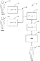
図1は、例示的なロボット手術システム(10)を図示する。システム(10)は、少なくとも1つのコントローラ(14)と、少なくとも1つのアームカート(18)とを含んでいる。アームカート(18)は、1つ又は複数のロボットマニピュレータ又はアーム(20)に機械的かつ/又は電気的に結合される。ロボットアーム(20)のそれぞれは、患者(24)に対して様々な外科的作業を実施するための1つ又は複数の手術器械(22)を備える。アーム(20)及び器械(22)を含めた、アームカート(18)の操作は、臨床医(12)によってコントローラ(14)から指示することができる。いくつかの例において、第2の臨床医(12’)によって操作される第2コントローラ(14’)もまた、第1の臨床医(12’)と協働してアームカート(18)の動作を指示し得る。例えば、臨床医(12、12’)の各々が、カートの異なるアーム(20)を制御してもよく、あるいは場合により、各臨床医(12、12’)間でアームカート(18)の全ての制御が受け渡されてもよい。いくつかの実施形態において、追加のアームカート(図示せず)が患者(24)に対して利用されてもよい。これらの追加のアームカートは、コントローラ(14、14’)のうちの1つ又は複数によって制御されてもよい。
I. Exemplary Robotic Surgical System Overview FIG. 1 illustrates an exemplary robotic surgical system (10). The system (10) includes at least one controller (14) and at least one arm cart (18). The arm cart (18) is mechanically and / or electrically coupled to one or more robot manipulators or arms (20). Each robotic arm (20) includes one or more surgical instruments (22) for performing various surgical tasks on the patient (24). Operation of the arm cart (18), including the arm (20) and the instrument (22), can be directed from the controller (14) by the clinician (12). In some examples, the second controller (14 ') operated by the second clinician (12') also cooperates with the first clinician (12 ') to operate the arm cart (18). Can be directed. For example, each clinician (12, 12 ′) may control a different arm (20) of the cart, or, optionally, all of the arm cart (18) between each clinician (12, 12 ′). Control may be passed. In some embodiments, an additional arm cart (not shown) may be utilized for the patient (24). These additional arm carts may be controlled by one or more of the controllers (14, 14 ').
アームカート(18)とコントローラ(14、14’)は、通信リンク(16)を介して互いに通信してもよく、通信リンク(16)は、任意の好適な通信プロトコルに従った、任意の好適な種類の信号(例えば、電気、光、赤外線など)を搬送する任意の好適な種類の有線の、かつ/又は無線の通信リンクであってよい。通信リンク(16)は実際の物理的リンクであってもよいし、あるいは、1つ又は複数の実際の物理的リンクを使用する論理的リンクであってもよい。ネットワークの各ノードを接続する通信設備を参照するためのコンピュータネットワークの分野で周知のように、リンクが論理的リンクである場合、物理的リンクの種類は、例えば、データリンクであっても、アップリンクであっても、ダウンリンクであっても、光ファイバリンクであっても、2地点間リンクであってもよい。 The arm cart (18) and the controller (14, 14 ') may communicate with each other via a communication link (16), which is in accordance with any suitable communication protocol. It can be any suitable type of wired and / or wireless communication link that carries any type of signal (eg, electricity, light, infrared, etc.). The communication link (16) may be an actual physical link, or may be a logical link using one or more actual physical links. As is well known in the field of computer networks for referencing communication equipment connecting each node of a network, if the link is a logical link, the physical link type may be, for example, a data link. It may be a link, a downlink, an optical fiber link, or a point-to-point link.
図2にシステム(10)のコントローラ(14)として機能する例示的コントローラ(30)を示す。この例では、コントローラ(30)は、一般的には、精密な使用者入力機構部(図示せず)を有する使用者入力アセンブリ(32)を備え、外科医は、この入力機構部を把持し、ステレオディスプレイ(34)を介して手術手技を見ながら空間的に操作する。使用者入力アセンブリ(32)の使用者入力機構部は、複数の自由度で動き、かつ(例えば、把持している鋸子を閉鎖したり、電極に電圧をかけたりなどするために)工具を直感的に作動させる作動ハンドルを備える手動式入力装置を備えてもよい。この例のコントローラ(30)はまた、外科医にアーム(20)及び器械(22)の更なる制御を提供するフットスイッチ(38)のアレイを備える。ディスプレイ(34)は、患者内部の手術部位を観察する1つ又は複数の内視鏡観察視野及び/又はその他の任意の好適な観察視野からの観察視野を示すことができる。加えて、フィードバックメータ(36)をディスプレイ(34)を通して見ることができ、外科医に対して、器械(22)の構成要素(例えば、切開する部材又は挟持する部材など)に加えられている力の量の視覚表示を提供する。他のセンサ構成を採用して、コントローラ(30)に、ステープルカートリッジが器械(22)のエンドエフェクタに装填されているか否か、器械(22)のアンビルが発射に先立って閉鎖位置へ移動されているか否か、及び/又は器械(22)のいくつかのその他の運転状態に関する表示を与えることもできる。 FIG. 2 shows an exemplary controller (30) that functions as the controller (14) of the system (10). In this example, the controller (30) generally comprises a user input assembly (32) having a precise user input mechanism (not shown), and the surgeon grasps the input mechanism, Spatial operation is performed while watching the surgical procedure via the stereo display (34). The user input mechanism of the user input assembly (32) moves in multiple degrees of freedom and makes the tool intuitive (e.g., to close the gripping saw and apply voltage to the electrodes). A manual input device with an actuating handle that is actuated automatically may be provided. The controller (30) of this example also includes an array of foot switches (38) that provide the surgeon with further control of the arm (20) and instrument (22). The display (34) may show a viewing field from one or more endoscopic viewing fields and / or any other suitable viewing field that observes the surgical site within the patient. In addition, the feedback meter (36) can be viewed through the display (34) and provides the surgeon with the force applied to the components of the instrument (22) (eg, the incising or clamping member). Provide visual indication of quantity. Other sensor configurations may be employed to allow the controller (30) to determine whether a staple cartridge is loaded into the end effector of the instrument (22), and to move the anvil of the instrument (22) to the closed position prior to firing. An indication of whether or not and / or some other operating state of the instrument (22) may also be provided.
図3にシステム(10)のアームカート(18)として機能することができる例示的ロボットアームカート(40)を示す。この例では、アームカート(40)は複数の手術器械(50)を作動させるように操作可能である。この例では3つの器械(50)を示すが、アームカート(40)は任意の好適な数の手術器械(50)を支持し作動させるように操作可能であってよい。手術器械(50)はそれぞれ、一般にセットアップ継手(44)と呼ばれる一連の手動による関節運動が可能な連結部と、ロボットマニピュレータ(46)とによって支持される。ここで、これらの構造は、ロボット連結部の大部分を覆って延在する保護カバーと共に示されている。これらの保護カバーは任意選択的なものであり、こうした装置を操作するために使用されるサーボ機構によって受ける慣性を最小化し、可動構成要素の容積を限定することで衝突を防止し、かつカート(40)の全体の重量を抑制するため、サイズを限定するか又は一部の変更例では完全に省略されてもよい。 FIG. 3 shows an exemplary robot arm cart (40) that can function as the arm cart (18) of the system (10). In this example, the arm cart (40) is operable to activate a plurality of surgical instruments (50). Although three instruments (50) are shown in this example, the arm cart (40) may be operable to support and operate any suitable number of surgical instruments (50). Each surgical instrument (50) is supported by a series of manually articulated connections, commonly referred to as set-up joints (44), and a robot manipulator (46). Here, these structures are shown with a protective cover that extends over most of the robotic connection. These protective covers are optional, minimize the inertia experienced by the servomechanisms used to operate such devices, prevent collisions by limiting the volume of movable components, and carts ( In order to reduce the overall weight of 40), the size may be limited or may be omitted entirely in some variations.
各ロボットマニピュレータ(46)の終端は、器械プラットフォーム(70)となっており、この器械プラットフォームは、マニピュレータ(46)によって枢動可能、回転可能、及びその他の方法で動作可能である。各プラットフォームは、器械(50)を更に位置決めするために一対の線路(74)に沿って摺動可能である器械ドック(72)を備える。この例ではそのような摺動運動は電動化されている。各器械ドック(72)は、器械(50)のインターフェースアセンブリ(52)と結合する機械的及び電気的インターフェースを備える。ほんの一例であるが、ドック(72)は、インターフェースアセンブリ(52)の相補的な回転入力と結合する、4個の回転出力を備えることが可能である。そのような回転駆動機構部は、器械(50)において、本明細書で引用した様々な参考文献に記述されているような、及び/又はより詳細に下記で説明されるような、様々な機能を駆動させ得る。電気的インターフェースは、物理的接触、誘導結合、及び/又はその他の方法によって通信を確立でき、かつ器械(50)の1つ又は複数の機構に電力を供給するように、器械(50)への命令及び/又はデータ通信を提供するように、及び/又は器械(50)からの命令及び/又はデータ通信を提供するように動作可能である。本明細書の教示を考慮することで、器械ドック(72)を器械(50)のインターフェースアセンブリ(52)と機械的及び電気的に通信することができる様々な適切な方法が、当業者に明らかであろう。器械(50)への/器械(50)からの、電力、及び/又は命令/データの通信を提供するために、器械(50)は、別個の電源及び/又はコントロールユニットと結合する1本又は複数本のケーブルを備えてもよいことが理解されるべきである。 The end of each robotic manipulator (46) is an instrument platform (70) that is pivotable, rotatable, and otherwise operable by the manipulator (46). Each platform includes an instrument dock (72) that is slidable along a pair of tracks (74) to further position the instrument (50). In this example, such sliding movement is motorized. Each instrument dock (72) includes a mechanical and electrical interface that couples to the interface assembly (52) of the instrument (50). By way of example only, dock (72) may comprise four rotational outputs that couple with complementary rotational inputs of interface assembly (52). Such a rotary drive mechanism may have various functions in the instrument (50) as described in the various references cited herein and / or as described in more detail below. Can be driven. The electrical interface can establish communication with the physical contact, inductive coupling, and / or other methods, and provide power to one or more mechanisms of the instrument (50) to the instrument (50). It is operable to provide command and / or data communication and / or to provide command and / or data communication from the instrument (50). In view of the teachings herein, a variety of suitable ways in which the instrument dock (72) can be in mechanical and electrical communication with the interface assembly (52) of the instrument (50) will be apparent to those skilled in the art. Will. To provide power and / or command / data communication to / from the instrument (50), the instrument (50) is coupled to a separate power source and / or control unit or It should be understood that multiple cables may be provided.
この例のアームカート(40)は、アームカート(40)を患者に対して選択的に位置決めするために、(例えば1人の係員によって)移動可能な基体(48)を備える。カート(40)は、一般的に、手術室間でカート(40)を輸送するのに好適な寸法を有していてよい。カート(40)は、標準的な手術室のドアを通り抜け、標準的な病院のエレベーターに乗せられるように構成することができる。また、いくつかの変更例では、自動化された器械再装填システム(図示せず)をアームカート(40)の動作範囲(60)の中又はその付近に配置し、器械(50)の構成要素(例えば、ステープルカートリッジなど)を選択的に再装填してもよい。 The arm cart (40) in this example includes a movable base (48) (eg, by one attendant) to selectively position the arm cart (40) with respect to the patient. The cart (40) may generally have dimensions suitable for transporting the cart (40) between operating rooms. The cart (40) can be configured to pass through a standard operating room door and ride on a standard hospital elevator. Also, in some variations, an automated instrument reloading system (not shown) is placed in or near the operating range (60) of the arm cart (40) and the components of the instrument (50) ( For example, a staple cartridge may be selectively reloaded.
前述のことに加えて、米国特許第5,792,135号、米国特許第5,817,084号、米国特許第5,878,193号、米国特許第6,231,565号、米国特許第6,783,524号、米国特許第6,364,888号、米国特許第7,524,320号、米国特許第7,691,098号、米国特許第7,806,891号、米国特許第7,824,401号、及び/又は米国公開特許第2013/0012957号の教示の少なくとも一部に従って、システム(10)の1つ又は複数の態様を構築することができることを理解されたい。前述の米国特許、及び米国公開特許のそれぞれの開示内容は、参照により本明細書に援用する。システム(10)に組み込み得る、更なる他の好適な機構及び手術性能(operability)が、本明細書の教示を考慮することで、当業者に明らかになるであろう。 In addition to the foregoing, US Pat. No. 5,792,135, US Pat. No. 5,817,084, US Pat. No. 5,878,193, US Pat. No. 6,231,565, US Pat. US Pat. No. 6,783,524, US Pat. No. 6,364,888, US Pat. No. 7,524,320, US Pat. No. 7,691,098, US Pat. No. 7,806,891, US Pat. It should be understood that one or more aspects of the system (10) can be constructed in accordance with at least part of the teachings of US Pat. No. 7,824,401 and / or US Published Patent No. 2013/0012957. The disclosures of each of the aforementioned US patents and US published patents are incorporated herein by reference. Still other suitable mechanisms and operability that can be incorporated into the system (10) will be apparent to those skilled in the art in view of the teachings herein.
II.関節機構を有する例示的な電気手術器械
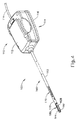
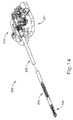
図4〜13は、システム(10)内で少なくとも1つの器械(50)として使用できる、例示的な電気手術器械(100)を示す。器械(100)の少なくとも一部は、米国特許第6,500,176号、米国特許第7,112,201号、米国特許第7,125,409号、米国特許第7,169,146号、米国特許第7,186,253号、米国特許第7,189,233号、米国特許第7,220,951号、米国特許第7,309,849号、米国特許第7,311,709号、米国特許第7,354,440号、米国特許第7,381,209号、米国公開特許第2011/0087218号、米国公開特許第2012/0116379号、米国公開特許第2012/0078243号、米国公開特許第2012/0078247号、米国公開特許第2013/0030428号、及び/又は米国公開特許第2013/0023868号の教示の少なくとも一部に従って構築し、動作可能である。これらの中に記載され、また、以下により詳細に記載されるように、器械(100)は、実質的に同時に、組織(例えば、血管など)を切開し、かつ、組織を封着し又は接合するように操作可能である。換言すれば、器械(100)は、器械(100)が、組織を接合する何筋かのステープルを提供する代わりに、バイポーラ高周波エネルギーの印加によって組織接合を提供すること以外は、エンドカッター型のステープラーと同様に動作する。また、器械(100)は、Ethicon Endo−Surgery,Inc.(Cincinnati、Ohio)によるENSEAL(登録商標)Tissue Sealing Deviceと様々な構造的及び機能的類似性を有してもよいことも理解されたい。更に、器械(100)は、本明細書で引用され参照されることによって本明細書に援用される他の参考文献のいずれかに教示される装置と様々な構造的かつ機能的類似点を有することがある。本明細書で引用された参考文献の教示と、Ethicon Endo−Surgery,Inc.(Cincinnati、Ohio)によるENSEAL(登録商標)Tissue Sealing Deviceと、器械(100)に関する以下の教示との間に存在する、ある程度の重複の範囲においては、本明細書の記載のいずれかを従来技術であると認める意図はない。事実、本明細書のいくつかの教示は、本明細書で引用された参考文献、及びEthicon Endo−Surgery,Inc.(Cincinnati、Ohio)によるENSEAL(登録商標)Tissue Sealing Deviceの教示の範囲を越える。
II. Exemplary Electrosurgical Instrument with Articulating Mechanism FIGS. 4-13 illustrate an exemplary electrosurgical instrument (100) that can be used as at least one instrument (50) within the system (10). At least a portion of the instrument (100) includes U.S. Patent No. 6,500,176, U.S. Patent No. 7,112,201, U.S. Patent No. 7,125,409, U.S. Patent No. 7,169,146, U.S. Patent No. 7,186,253, U.S. Patent No. 7,189,233, U.S. Patent No. 7,220,951, U.S. Patent No. 7,309,849, U.S. Patent No. 7,311,709, US Patent No. 7,354,440, US Patent No. 7,381,209, US Published Patent No. 2011/0087218, US Published Patent No. 2012/0116379, US Published Patent No. 2012/0078243, US Published Patent At least one of the teachings of US 2012/0078247, US 2013/0030428, and / or US 2013/0023868. Constructed according to, it is operational. As described therein and as described in more detail below, the instrument (100) dissects tissue (eg, a blood vessel, etc.) and seals or joins tissue substantially simultaneously. It is possible to operate. In other words, the instrument (100) is an end-cutter type, except that the instrument (100) provides tissue bonding by application of bipolar radio frequency energy instead of providing several staples to bond tissue. Works like a stapler. Instrument (100) is also available from Ethicon Endo-Surgery, Inc. It should also be understood that it may have a variety of structural and functional similarities to ENSEAL® Tissue Sealing Device by (Cincinnati, Ohio). Further, the instrument (100) has various structural and functional similarities to the apparatus taught in any of the other references incorporated herein by reference and cited herein. Sometimes. The teachings of the references cited herein and Ethicon Endo-Surgery, Inc. To the extent of some overlap existing between the ENSEAL® Tissue Sealing Device by (Cincinnati, Ohio) and the following teachings on the instrument (100), any of the descriptions herein are There is no intention to admit. In fact, some teachings of the present specification can be found in the references cited herein, and Ethicon Endo-Surgery, Inc. (Cincinnati, Ohio) is beyond the scope of the teaching of ENSEAL® Tissue Sealing Device.
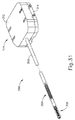
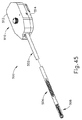
この例の器械(100)は、インターフェースアセンブリ(110)と、シャフトアセンブリ(160)と、関節セクション(170)と、エンドエフェクタ(180)と、を備えている。以下で更に詳細に説明するように、インターフェースアセンブリ(110)はロボットアームカート(40)のドック(72)と結合するように構成されており、更にそれによって関節セクション(170)及びエンドエフェクタ(180)を駆動するように操作可能である。また、更に以下により詳細に記載されるように、器械(100)は、エンドエフェクタ(180)を関節運動させて、組織(例えば、太い血管など)に対して所望の位置決めを提供し、次いでエンドエフェクタ(180)を用いて組織を切開し、組織にバイポーラ高周波エネルギーを印加することによって組織を封着するように動作可能である。 The example instrument (100) includes an interface assembly (110), a shaft assembly (160), a joint section (170), and an end effector (180). As described in more detail below, the interface assembly (110) is configured to couple with the dock (72) of the robot arm cart (40), thereby further providing a joint section (170) and end effector (180). ) Can be operated. Also, as described in more detail below, the instrument (100) articulates the end effector (180) to provide the desired positioning with respect to tissue (eg, a large blood vessel) and then the end The effector (180) is used to incise the tissue and to seal the tissue by applying bipolar high frequency energy to the tissue.
A.例示的なシャフトアセンブリ及び関節セクション
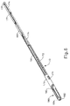
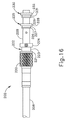
この例のシャフトアセンブリ(160)はインターフェースアセンブリ(110)から遠位方向に延在する。関節セクション(170)は、シャフトアセンブリ(160)の遠位端に位置し、エンドエフェクタ(180)は、関節セクション(170)に対して遠位に位置している。シャフトアセンブリ(160)は、インターフェースアセンブリ(110)を関節セクション(170)及びエンドエフェクタ(180)と結合する駆動機構部及び電気機構部を収容する外側シース(162)を備える。図5にて最もよく見て取れるように、シャフトアセンブリ(160)は、一体化した回転結合部(164)及び発射ビーム結合部(166)を更に備える。回転結合部(164)によって、シャフトアセンブリ(160)は、シース(162)によって規定される長手方向軸を中心に、インターフェースアセンブリ(110)に対して回転可能である。そのような回転により、エンドエフェクタ(180)、関節セクション(170)、及びシャフトアセンブリ(160)の一体的な回転を提供してもよい。いくつかの他の変更例では、回転結合部(164)は、関節セクション(170)の近位のシャフトアセンブリ(160)のいずれの部分も回転させることなく、エンドエフェクタ(180)を回転させるように操作可能である。別の単なる実例として、器械(100)は、シャフトアセンブリ(160)及びエンドエフェクタ(180)を単一のユニットとして回転させることができる1つの回転制御、又は、関節セクション(170)の近位のシャフトアセンブリ(160)のいずれの部分も回転させることなく、エンドエフェクタ(180)を回転させることができる別の回転制御を含んでもよい。本明細書の教示を考慮することで、他の好適な回転スキームが、当業者に明らかになるであろう。当然ながら、回転可能な機構部は、所望により、単に省略されてもよい。
A. Exemplary Shaft Assembly and Joint Section The shaft assembly (160) of this example extends distally from the interface assembly (110). The articulation section (170) is located at the distal end of the shaft assembly (160) and the end effector (180) is located distal to the articulation section (170). The shaft assembly (160) includes an outer sheath (162) that houses a drive mechanism and electrical mechanism that couples the interface assembly (110) with the articulation section (170) and the end effector (180). As best seen in FIG. 5, the shaft assembly (160) further comprises an integrated rotational coupling (164) and firing beam coupling (166). The rotational coupling (164) allows the shaft assembly (160) to rotate relative to the interface assembly (110) about a longitudinal axis defined by the sheath (162). Such rotation may provide integral rotation of the end effector (180), articulation section (170), and shaft assembly (160). In some other modifications, the rotational coupling (164) rotates the end effector (180) without rotating any portion of the shaft assembly (160) proximal of the articulation section (170). Can be operated. As another mere example, the instrument (100) is a single rotational control that can rotate the shaft assembly (160) and end effector (180) as a single unit, or proximal of the articulation section (170). Another rotation control may be included that allows the end effector (180) to rotate without rotating any portion of the shaft assembly (160). Other suitable rotation schemes will be apparent to those skilled in the art in view of the teachings herein. Of course, the rotatable mechanism may simply be omitted if desired.
関節セクション(170)は、シース(162)によって規定される長手方向軸に対して様々な角度で、エンドエフェクタ(180)を選択的に位置決めするように操作可能である。関節セクション(170)は、種々の形態をとってよい。ほんの一例であるが、関節セクション(170)は、参照により本明細書に援用される米国公開特許第2012/0078247号の1つ又は複数の教示に従って構成することができる。別の単なる実例として、関節セクション(170)は、参照により本明細書に援用される米国公開特許第2012/0078248号、発明の名称「Articulation Joint Features for Articulating Surgical Device」(2012年3月29日公開)の1つ又は複数の教示に従って構成することができる。本明細書の教示を考慮することで、関節セクション(170)がとり得る様々な他の好適な形態が、当業者に明らかになるであろう。また、器械(10)の一部の変更例では、関節セクション(170)を単に欠いていてもよいことを理解されたい。 The articulation section (170) is operable to selectively position the end effector (180) at various angles with respect to the longitudinal axis defined by the sheath (162). The joint section (170) may take various forms. By way of example only, joint section (170) may be configured in accordance with one or more teachings of US Published Patent Application No. 2012/0078247, which is incorporated herein by reference. As another mere example, the joint section (170) is disclosed in US Publication No. 2012/0078248, entitled “Articulation Joint Features for Articulating Surgical Devices” (March 29, 2012), incorporated herein by reference. Can be configured in accordance with one or more teachings of (public). Various other suitable forms that the articulation section (170) may take will be apparent to those skilled in the art in view of the teachings herein. It should also be appreciated that some modifications of the instrument (10) may simply lack the articulation section (170).
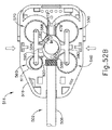
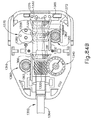
図6〜7にて最もよく見て取れるように、この例の関節セクション(170)はリブ付き本体(172)を備え、リブ付き本体(172)を貫通して延在する一対の関節ビーム(174、176)を有する。図6では、リブ付き本体(172)の上半分を省略している。関節ビーム(174、176)は、エンドエフェクタ(180)と関節セクション(170)との間に位置するチューブ(178)内部で遠位に固定される。関節ビーム(174、176)は、シース(162)によって規定された長手方向軸から離れる方向にエンドエフェクタ(180)を横方向に偏向させることによって、エンドエフェクタ(180)を関節運動させるように操作可能である。具体的には、図7に示す図を参照すると、関節ビーム(174)を近位方向に後退させつつ、関節ビーム(176)を遠位方向に前進させると、エンドエフェクタ(180)は関節ビーム(174)に向かって偏向する。関節ビーム(176)を近位方向に後退させつつ、関節ビーム(174)を遠位方向に前進させると、エンドエフェクタ(180)は関節ビーム(176)に向かって偏向する。関節ビーム(174、176)がどのように反対方向に平行移動するかの単なる実例が、以下により詳細に説明されるが、本明細書の教示を考慮することで、更に他の例が当業者にとって明らかであろう。図6にて最もよく見て取れるように、スペーサ体(177)が関節ビーム(174、176)の間に位置付けされ、かつ実質的に直線的に、分離された関係でビーム(174、176)を維持するように動作可能である。 As best seen in FIGS. 6-7, the articulating section (170) of this example comprises a ribbed body (172) and a pair of articulating beams (174, 174) extending through the ribbed body (172). 176). In FIG. 6, the upper half of the ribbed main body (172) is omitted. The joint beams (174, 176) are fixed distally within a tube (178) located between the end effector (180) and the joint section (170). The articulating beams (174, 176) are manipulated to articulate the end effector (180) by laterally deflecting the end effector (180) away from the longitudinal axis defined by the sheath (162). Is possible. Specifically, referring to the view shown in FIG. 7, when the joint beam (176) is advanced distally while the joint beam (174) is retracted proximally, the end effector (180) is Deflection towards (174). When the joint beam (174) is advanced distally while the joint beam (176) is retracted proximally, the end effector (180) deflects toward the joint beam (176). A mere example of how the joint beam (174, 176) translates in the opposite direction is described in more detail below, but further examples will become apparent to those skilled in the art in view of the teachings herein. It will be obvious to you. As best seen in FIG. 6, a spacer body (177) is positioned between the joint beams (174, 176) and maintains the beams (174, 176) in a substantially linear, separated relationship. It is possible to operate.
B.例示的なエンドエフェクタ
この例のエンドエフェクタ(180)は、第1つかみ具(182)と、第2つかみ具(184)と、を備える。この例では、第1つかみ具(182)は、シャフトアセンブリ(160)に対して実質的に固定され、一方、第2つかみ具(184)は、第1つかみ具(182)に向かって、また、第1つかみ具(182)から離れる方向に、シャフトアセンブリ(160)に対して枢動する。いくつかの変更例において、ロッド又はケーブルなどのアクチュエータが、シース(162)を通って延在し、かつ枢動結合部において第2つかみ具(184)と接合されてもよく、これにより、シャフトアセンブリ(160)を通るアクチュエータロッド/ケーブルなどの長手方向の移動により、シャフトアセンブリ(160)及び第1つかみ具(182)に対する第2つかみ具(184)の枢動がもたらされるようにしてもよい。当然ながら、つかみ具(182、184)は、代わりに、任意の他の好適な種類の移動を有してもよく、かつ任意の他の好適な方法で作動されてもよい。ほんの一例であるが、以下により詳細に記載されるように、いくつかの変更例においては、つかみ具(182、184)は、発射ビーム(190)の長手方向平行移動によって作動され、閉鎖することができ、アクチュエータロッド/ケーブルなどを単に排除することができる。
B. Exemplary End Effector The end effector (180) of this example includes a first grip (182) and a second grip (184). In this example, the first grip (182) is substantially fixed relative to the shaft assembly (160), while the second grip (184) is toward the first grip (182) and Pivot relative to the shaft assembly (160) in a direction away from the first jaw (182). In some variations, an actuator, such as a rod or cable, may extend through the sheath (162) and be joined to the second grip (184) at the pivot joint so that the shaft Longitudinal movement of an actuator rod / cable or the like through assembly (160) may cause pivoting of second grip (184) relative to shaft assembly (160) and first grip (182). . Of course, the grippers (182, 184) may instead have any other suitable type of movement and may be actuated in any other suitable manner. By way of example only, as will be described in more detail below, in some variations, the gripper (182, 184) is actuated by the longitudinal translation of the firing beam (190) to close. The actuator rod / cable etc. can simply be eliminated.
図8〜9にて最もよく見て取れるように、第1つかみ具(182)は、長手方向に延在する細長いスロット(183)を画定し、一方、第2つかみ具(184)も、長手方向に延在する細長いスロット(185)を画定する。加えて、第1つかみ具(182)の上面は、第1電極表面(186)を提供し、一方、第2つかみ具(184)の下面は、第2電極表面(187)を提供する。電極表面(186、187)は、シャフトアセンブリ(160)の長さに沿って延在する1つ又は複数の導電体(図示せず)を介して、電源(102)と連通している。電源(102)は、高周波電流が、電極表面(186、187)の間を流れ、それによってつかみ具(182、184)の間に捕捉された組織を通るように、第1電極表面(186)に第1の極性で、かつ第2電極表面(187)に第2の(逆の)極性で高周波エネルギーを送達するように動作可能である。いくつかの変更例において、発射ビーム(190)は、つかみ具(182、184)の間に捕捉されたバイポーラ高周波エネルギーを送達するために、電極表面(186、187)と協働する導電体として(例えば、接地帰路として)機能する。 As best seen in FIGS. 8-9, the first grip (182) defines an elongated slot (183) extending in the longitudinal direction, while the second grip (184) is also in the longitudinal direction. An elongated slot (185) is defined that extends. In addition, the upper surface of the first grip (182) provides a first electrode surface (186), while the lower surface of the second grip (184) provides a second electrode surface (187). The electrode surfaces (186, 187) are in communication with a power source (102) via one or more conductors (not shown) extending along the length of the shaft assembly (160). The power source (102) allows the high frequency current to flow between the electrode surfaces (186, 187) and thereby through the tissue captured between the grippers (182, 184), so that the first electrode surface (186). At a first polarity and to a second electrode surface (187) with a second (reverse) polarity. In some variations, the firing beam (190) is a conductor that cooperates with the electrode surfaces (186, 187) to deliver bipolar radio frequency energy captured between the grippers (182, 184). Function (eg, as a ground return).
電源(102)は、本明細書の1つ若しくは複数の参照文献に記載されるように、又は別の方法で、器械(100)の外部にあってもよいし、又は器械(100)と一体であってもよい。コントローラ(104)は、電源(102)から電極表面(186、187)への電力の送達を調節する。コントローラ(104)は、本明細書の1つ若しくは複数の参照文献に記載されるように、又は別の方法で、器械(100)の外部にあってもよいし、又は電気手術器械(100)と一体であってもよい。また、電極表面(186、187)は、様々な代替的配置、構成、及び関係で提供されてもよいことも理解されたい。電源(102)及び/又はコントローラ(104)は、米国仮特許出願第61/550,768号、発明の名称「Medical Instrument」(2011年10月24日発行、その開示内容を参照により本明細書に援用する。)、米国公開特許第2011/0082486号、発明の名称「Devices and Techniques for Cutting and Coagulating Tissue」(2011年4月7日公開、その開示内容を参照により本明細書に援用する。)、米国公開特許第2011/0087212号、発明の名称「Surgical Generator for Ultrasonic and Electsurgical Devices」(2011年4月14日公開、その開示内容を参照により本明細書に援用する。)、米国公開特許第2011/0087213号、発明の名称「Surgical Generator for Ultrasonic and Electsurgical Devices」(2011年4月14日公開、その開示内容を参照により本明細書に援用する。)、米国公開特許第2011/0087214号、発明の名称「Surgical Generator for Ultrasonic and Electsurgical Devices」(2011年4月14日公開、その開示内容を参照により本明細書に援用する。)、米国公開特許第2011/0087215号、発明の名称「Surgical Generator for Ultrasonic and Electsurgical Devices」(2011年4月14日公開、その開示内容を参照により本明細書に援用する。)、米国公開特許第2011/0087216号、発明の名称(Surgical Generator for Ultrasonic and Electsurgical Devices」(2011年4月14日公開、その開示内容を参照により本明細書に援用する。)、米国公開特許第2011/0087217号、発明の名称(Surgical Generator for Ultrasonic and Electsurgical Devices」(2011年4月14日公開、その開示内容を参照により本明細書に援用する。)の教示の少なくとも一部に従って構成することができることも理解されたい。本明細書の教示を考慮することで、電源(102)及びコントローラ(104)のその他の好適な構成が、当業者には明らかとなるであろう。 The power source (102) may be external to the instrument (100) or otherwise integrated with the instrument (100), as described in one or more references herein. It may be. The controller (104) regulates the delivery of power from the power source (102) to the electrode surfaces (186, 187). The controller (104) may be external to the instrument (100) as described in one or more references herein, or otherwise, or the electrosurgical instrument (100). And may be integrated. It should also be understood that the electrode surfaces (186, 187) may be provided in various alternative arrangements, configurations, and relationships. The power source (102) and / or the controller (104) is disclosed in US Provisional Patent Application No. 61 / 550,768, entitled “Medical Instrument” (issued 24 October 2011, the disclosure of which is hereby incorporated herein by reference). U.S. Published Patent No. 2011/0082486, title of the invention “Devices and Techniques for Cutting and Coagulating Tissue” (published April 7, 2011, the disclosure of which is incorporated herein by reference). ), U.S. Published Patent No. 2011/0087212, title of the invention "Surgical Generator for Ultrasonic and Electrical Devices" (published on April 14, 2011, disclosed content thereof) U.S. Patent Publication No. 2011/0087213, title of invention "Surgical Generator for Ultrasonic and Electrical Devices" (published on April 14, 2011, the disclosure of which is incorporated herein by reference) U.S. Published Patent No. 2011/0087214, Title of Invention “Surgical Generator for Ultrasonic and Electrical Devices” (published on Apr. 14, 2011, the disclosure of which is incorporated herein by reference). ), U.S. Published Patent No. 2011/0087215, title of invention “Surgical Generator for Ultrasonic and Electrics” "Urical Devices" (published on April 14, 2011, the disclosure of which is incorporated herein by reference), U.S. Published Patent No. 2011/0087216, Title of Invention (Surgical Generator for Ultrasonic Devices "(2011 Published on April 14, 2011, the disclosure of which is incorporated herein by reference.), US Published Patent No. 2011/0087217, Title of Invention (Surgical Generator for Ultrasonics and Electrical Devices) (April 14, 2011 The disclosure of the disclosure is incorporated herein by reference. It should also be understood that it can be constructed in accordance with at least some of the teachings of Other suitable configurations of the power supply (102) and controller (104) will be apparent to those skilled in the art in view of the teachings herein.
図9にて最もよく見て取れるように、第1つかみ具(182)の下面は、スロット(183)に隣接し、長手方向に延在する陥凹(197)を備え、一方第2つかみ具(184)の上面は、スロット(185)に隣接し、長手方向に延在する陥凹(193)を備える。図2は、複数の鋸歯状歯(188)を含む、第1つかみ具(182)の上面を示す。組織を引き裂く必要なく、つかみ具(182、184)の間に捕捉される組織の把持性を向上させるために、第2つかみ具(184)の下面は、鋸歯(188)と入れ子の相補的な鋸歯を備えてもよいことを理解されたい。当然ながら、鋸歯(188)は、任意の他の好適な形態をとってもよいし、又は単に全て省略されてもよい。また、鋸歯(188)は、例えば、プラスチック、ガラス、及び/若しくはセラミックなどの非導電性又は絶縁性の材料で形成されてもよいし、また、組織がつかみ具(182、184)に詰まるのを実質的に防止するために、ポリテトラフルオロエチレン、潤滑剤などの処理剤(treatment)、又は他の処理剤を含んでもよいことも理解されたい。 As best seen in FIG. 9, the lower surface of the first grip (182) is provided with a longitudinally extending recess (197) adjacent to the slot (183), while the second grip (184). ) Is provided with a recess (193) extending longitudinally adjacent to the slot (185). FIG. 2 shows the top surface of the first jaw (182), which includes a plurality of serrated teeth (188). In order to improve the grip of the tissue captured between the jaws (182, 184) without having to tear the tissue, the lower surface of the second jaw (184) is complementary to the saw teeth (188) and nested. It should be understood that serrations may be provided. Of course, the saw blades (188) may take any other suitable form or may simply be omitted entirely. The saw blade (188) may also be formed of a non-conductive or insulating material such as, for example, plastic, glass, and / or ceramic, and the tissue is jammed in the gripper (182, 184). It should also be understood that polytetrafluoroethylene, treatments such as lubricants, or other treatments may be included to substantially prevent this.
当然ながら、所望により、器械(100)を切開処置で使用することもできるが、シャフトアセンブリ(160)及びエンドエフェクタ(180)は、器械(100)が最小侵襲的な手術で使用可能であるように、つかみ具(182、184)が閉鎖位置にある状態で、様々な内径を有するトロカールを通り抜けさせるように寸法決定され、構成される。ほんの一例であるが、シャフトアセンブリ(160)及びエンドエフェクタ(180)は、つかみ具(182、184)を閉鎖位置にした状態で、約5mmの外径を呈してよい。あるいは、シャフトアセンブリ(160)及びエンドエフェクタ(180)は、任意の他の好適な外径(例えば約2mm〜約20mmなど)を呈してよい。 Of course, if desired, the instrument (100) may be used in an incision procedure, but the shaft assembly (160) and end effector (180) may allow the instrument (100) to be used in minimally invasive surgery. And sized and configured to pass through trocars having various inner diameters with the grippers (182, 184) in the closed position. By way of example only, shaft assembly (160) and end effector (180) may exhibit an outer diameter of about 5 mm with grippers (182, 184) in a closed position. Alternatively, shaft assembly (160) and end effector (180) may exhibit any other suitable outer diameter (eg, about 2 mm to about 20 mm, etc.).
いくつかの変更例において、エンドエフェクタ(180)は、エンドエフェクタ(180)における様々なパラメータを感知するように構成される、1つ又は複数のセンサ(図示せず)を備え、該パラメータとしては、隣接組織の温度、隣接組織の電気抵抗又はインピーダンス、隣接組織を通した電圧、隣接組織がつかみ具(182、184)に加える力などが挙げられるが、これらに限定されない。ほんの一例であるが、エンドエフェクタ(180)は、電極(186、187)に隣接して、かつ/又は他所に配置された、1つ又は複数の正の温度係数(PTC)のサーミスタ体(189)(例えば、PTCポリマーなど)を備えてもよい。センサからのデータは、コントローラ(104)に通信することができる。コントローラ(104)は、そのようなデータを様々な方法で処理してよい。ほんの一例であるが、コントローラ(104)は、エンドエフェクタ(180)における1つ又は複数のセンサから取得されるデータに少なくとも部分的に基づいて、電極表面(186、187)に送達される高周波エネルギーを調節する、ないしは別の方法で変化させてもよい。加えて、又は代替的に、コントローラ(104)は、エンドエフェクタ(180)の1つ又は複数のセンサから取得されるデータに少なくとも部分的に基づいて、音響及び/又は視覚フィードバック装置(例えば、スピーカ、ライト、表示画面など)を介して、1つ又は複数の状態を使用者に警告してもよい。また、一部の種類のセンサは、必ずしもコントローラ(104)と通信している必要はなく、エンドエフェクタ(180)での純粋に局部的な作用を単に提供してもよいことも理解されたい。例えば、エンドエフェクタ(180)におけるPTCサーミスタ体(189)は、組織及び/又はエンドエフェクタ(180)の温度が上昇するにつれて、電極表面(186、187)でのエネルギー送達を自動的に減少させ、それによって過熱の可能性を低減することができる。いくつかのそのような変更例では、PTCサーミスタ要素は、電源(102)及び電極表面(186、187)と直列であり、このPTCサーミスタは、温度が閾値を超えるのに応じて、インピーダンスを増加させる(電流を減少させる)。更に、電極表面(186、187)は、センサ(例えば、組織のインピーダンスなどを感知するためなどの)として使用することができることを理解されたい。本明細書の教示を考慮することで、器械(100)に組み込み得る様々な種類のセンサが、当業者に明らかになるであろう。同様に、本明細書の教示を考慮することで、コントローラ(104)によって、ないしは別の方法で、センサからのデータを用いて行い得る様々なことが、当業者に明らかになるであろう。また、本明細書の教示を考慮することで、エンドエフェクタ(180)の他の好適な変形例も、当業者に明らかになるであろう。 In some variations, the end effector (180) comprises one or more sensors (not shown) configured to sense various parameters in the end effector (180), including: , Adjacent tissue temperature, electrical resistance or impedance of the adjacent tissue, voltage through the adjacent tissue, force applied by the adjacent tissue to the gripper (182, 184), and the like. By way of example only, the end effector (180) may include one or more positive temperature coefficient (PTC) thermistor bodies (189) disposed adjacent to and / or elsewhere in the electrodes (186, 187). ) (For example, PTC polymer). Data from the sensor can be communicated to the controller (104). The controller (104) may process such data in various ways. By way of example only, the controller (104) is capable of delivering radio frequency energy to the electrode surfaces (186, 187) based at least in part on data obtained from one or more sensors in the end effector (180). May be adjusted or changed in other ways. In addition or alternatively, the controller (104) may be configured to provide an acoustic and / or visual feedback device (eg, a speaker) based at least in part on data obtained from one or more sensors of the end effector (180). , Lights, display screens, etc.) one or more states may be alerted to the user. It should also be understood that some types of sensors need not necessarily be in communication with the controller (104), but may simply provide purely local action at the end effector (180). For example, the PTC thermistor body (189) at the end effector (180) automatically reduces energy delivery at the electrode surface (186, 187) as the temperature of the tissue and / or end effector (180) increases. Thereby, the possibility of overheating can be reduced. In some such modifications, the PTC thermistor element is in series with the power supply (102) and the electrode surfaces (186, 187), which increases impedance as the temperature exceeds a threshold. (Reduce the current). Furthermore, it should be understood that the electrode surfaces (186, 187) can be used as sensors (eg, for sensing tissue impedance, etc.). In view of the teachings herein, various types of sensors that can be incorporated into the instrument (100) will be apparent to those skilled in the art. Similarly, in light of the teachings herein, it will be apparent to those skilled in the art that various things can be done with the data from the sensor by the controller (104) or otherwise. Also, other suitable variations of the end effector (180) will be apparent to those skilled in the art in view of the teachings herein.
発射ビーム(190)はエンドエフェクタ(180)の長さの一部に沿って長手方向に移動可能である。発射ビーム(190)は、シャフトアセンブリ(160)内で同軸に位置付けられ、シャフトアセンブリ(160)の長さの一部に沿って延在し、シャフトアセンブリ(160)内で(この例では、関節セクション(170)を含む)長手方向に平行移動するが、発射ビーム(190)とシャフトアセンブリ(160)とは、任意の他の好適な関係を有してもよいことを理解されたい。図6に見られるように、発射ビーム(190)は発射ブロック(168)に固定され、その結果発射ビーム(190)と発射ブロック(168)とはシース(162)内部で共に一体となって平行移動する。発射ブロック(168)が発射チューブ(167)に固定されていることは、図5にて最もよく見て取れる。発射ブロック(168)と発射チューブ(167)とは、シース(162)内部で共に一体となって平行移動する。発射ビーム結合部(166)は発射チューブ(167)に固定され、発射ビーム結合部(166)の平行移動により、上記の結合を介して発射ビーム(190)が平行移動させられることになる。 The firing beam (190) is movable longitudinally along a portion of the length of the end effector (180). The firing beam (190) is positioned coaxially within the shaft assembly (160), extends along a portion of the length of the shaft assembly (160), and within the shaft assembly (160) (in this example, a joint While translating longitudinally (including section (170)), it should be understood that firing beam (190) and shaft assembly (160) may have any other suitable relationship. As can be seen in FIG. 6, the firing beam (190) is secured to the firing block (168) so that the firing beam (190) and the firing block (168) are integral and parallel together within the sheath (162). Moving. It can best be seen in FIG. 5 that the firing block (168) is secured to the firing tube (167). The firing block (168) and the firing tube (167) are translated together integrally within the sheath (162). The launch beam coupler (166) is fixed to the launch tube (167), and the parallel movement of the launch beam coupler (166) translates the launch beam (190) via the coupling.
発射ビーム(190)は、鋭利な遠位ブレード(194)と、上側フランジ(192)と、下側フランジ(196)と、を備える。図8〜9にて最もよく見て取れるように、遠位ブレード(194)は、つかみ具(182、184)のスロット(183、185)を通って延在し、上側フランジ(192)は、陥凹(59)内にて、つかみ具(184)の上方に配置され、下側フランジ(196)は、陥凹(58)内にて、つかみ具(182)の下方に配置される。この遠位ブレード(194)及びフランジ(62、66)の構成により、発射ビーム(190)の遠位端では、「I形ビーム」型の断面がもたらされる。この例では、フランジ(192、196)は、発射ビーム(190)の長さのわずかな部分のみに沿って長手方向に延在するが、フランジ(192、196)は、発射ビーム(190)の任意の好適な長さに沿って長手方向に延在していてもよいことを理解されたい。加えて、フランジ(192、196)は、つかみ具(182、184)の外側に沿って位置決めされているが、代替的には、フランジ(192、196)は、つかみ具(182、184)内に形成された対応するスロット内に配置されていてもよい。例えば、それぞれのつかみ具(182、184)が、「T字」形状のスロットを画定し、遠位ブレード(194)の部分が、それぞれの「T字」形状のスロットの1つの垂直部分内に配置され、フランジ(192、196)が、「T字」形状のスロットの水平部分内に配置されてもよい。本明細書の教示を考慮することで、様々な他の好適な構成及び関係が、当業者に明らかになるであろう。 The firing beam (190) includes a sharp distal blade (194), an upper flange (192), and a lower flange (196). As best seen in FIGS. 8-9, the distal blade (194) extends through the slots (183, 185) of the gripper (182, 184) and the upper flange (192) is recessed. Within (59), the grip (184) is positioned above and the lower flange (196) is positioned within the recess (58) below the grip (182). This distal blade (194) and flange (62, 66) configuration provides a “I-beam” shaped cross section at the distal end of the firing beam (190). In this example, the flanges (192, 196) extend longitudinally along only a small portion of the length of the firing beam (190), whereas the flanges (192, 196) are of the firing beam (190). It should be understood that it may extend longitudinally along any suitable length. In addition, the flanges (192, 196) are positioned along the outside of the grips (182, 184), but alternatively the flanges (192, 196) are within the grips (182, 184). It may be arranged in a corresponding slot formed in. For example, each gripper (182, 184) defines a “T” shaped slot, and a portion of the distal blade (194) is within one vertical portion of each “T” shaped slot. Arranged and flanges (192, 196) may be placed in the horizontal portion of the "T" shaped slot. Various other suitable configurations and relationships will be apparent to those skilled in the art in view of the teachings herein.
遠位ブレード(194)は、遠位ブレード(194)がつかみ具(182、184)の間に捕捉される組織を容易に切開するように、実質的に鋭利である。また、この例では、遠位ブレード(194)は、電気的に接地されており、本明細書の他の場所に記載されるように、高周波エネルギーのための帰路を提供する。いくつかの他の変更例において、遠位ブレード(194)は、アクティブ電極として機能する。加えて、又は代替的に、遠位ブレード(194)は、超音波エネルギー(例えば、約55.5kHzの調和振動など)で選択的にエネルギーを与えられてもよい。 The distal blade (194) is substantially sharp so that the distal blade (194) easily dissects the tissue captured between the grippers (182, 184). Also in this example, the distal blade (194) is electrically grounded and provides a return path for high frequency energy, as described elsewhere herein. In some other variations, the distal blade (194) functions as an active electrode. Additionally or alternatively, the distal blade (194) may be selectively energized with ultrasonic energy (eg, harmonic vibration of about 55.5 kHz).
発射ビーム(190)の「I形ビーム」型の構成により、発射ビーム(190)が遠位に前進させられると、つかみ具(182、184)が閉鎖される。具体的には、発射ビーム(190)が近位位置から遠位位置に前進させられると、フランジ(192)が、つかみ具(184)内に形成された陥凹(193)に押し当てられることによって、つかみ具(184)を、つかみ具(182)に向かって枢動させるように付勢する。発射ビーム(190)によるつかみ具(182、184)に対する閉鎖効果は、遠位ブレード(194)がつかみ具(182、184)の間で捕捉された組織に到達する前に生じ得る。発射ビーム(190)がそのような段階を経ることで、発射ストローク全体を通して、発射ビーム(190)を遠位に作動させるために要求される力を低減することができる。換言すれば、いくつかのそのような変更例では、発射ビーム(190)は、つかみ具(182、184)の間に捕捉された組織を切開することによる抵抗を受ける前に、組織上でつかみ具(182、184)を実質的に閉鎖するために必要とされる初期抵抗を既に克服していてもよい。当然ながら、任意の他の好適な段階が提供されてもよい。 Due to the "I-beam" type configuration of the firing beam (190), the grippers (182, 184) are closed when the firing beam (190) is advanced distally. Specifically, when the firing beam (190) is advanced from the proximal position to the distal position, the flange (192) is pressed against the recess (193) formed in the gripper (184). To urge the gripper (184) to pivot toward the gripper (182). The closing effect on the jaws (182, 184) by the firing beam (190) may occur before the distal blade (194) reaches the tissue captured between the jaws (182, 184). The firing beam (190) undergoes such steps to reduce the force required to actuate the firing beam (190) distally throughout the firing stroke. In other words, in some such modifications, the firing beam (190) is grasped on the tissue before it is resisted by incising the tissue captured between the graspers (182, 184). The initial resistance required to substantially close the device (182, 184) may already be overcome. Of course, any other suitable stage may be provided.
この例では、フランジ(192)は、発射ビーム(190)が近位位置に後退させられる際につかみ具(184)を開放し、かつ発射ビーム(190)が近位位置に留まる際につかみ具(184)を開放状態に保持するように、つかみ具(184)の近位端の傾斜面形状に対してカム係合するように構成される。このカム係合が可能であることにより、つかみ具(182、184)を閉鎖位置から強制的に離すことによって、組織の層を分離するため、鈍的切開を実施するためなどにエンドエフェクタ(180)を使用しやすくなり得る。いくつかの他の変更例において、つかみ具(182、184)は、ばね又は他の種類の弾性機構によって、開放位置に弾性的に付勢される。この例では、つかみ具(182、184)は、発射ビーム(190)が平行移動される際に閉鎖又は開放するが、他の変更例においては、つかみ具(182、184)及び発射ビーム(190)の独立した動きが提供され得ることを理解されたい。ほんの一例であるが、1つ又は複数のケーブル、ロッド、ビーム、又はその他の機構が、シャフトアセンブリ(160)を通って延在し、発射ビーム(190)と独立してつかみ具(182、184)を選択的に作動させてもよい。 In this example, the flange (192) opens the grip (184) when the firing beam (190) is retracted to the proximal position and the grip when the firing beam (190) remains in the proximal position. It is configured to cam-engage against the ramp profile at the proximal end of the gripper (184) so as to hold (184) open. This cam engagement allows the end effector (180, such as to separate tissue layers by forcing the grippers (182, 184) away from the closed position, to perform blunt dissections, etc. ) May be easier to use. In some other variations, the gripper (182, 184) is elastically biased to the open position by a spring or other type of elastic mechanism. In this example, the grippers (182, 184) close or open when the firing beam (190) is translated, but in other variations, the grippers (182, 184) and the firing beam (190). It is to be understood that independent movements can be provided. By way of example only, one or more cables, rods, beams, or other mechanisms extend through the shaft assembly (160) and are independent of the firing beam (190) and the grips (182, 184). ) May be selectively activated.
C.例示的なロボット・アーム・インターフェース・アセンブリ
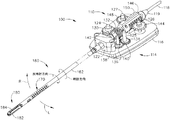
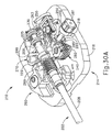
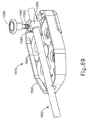
図4及び図10〜13は、この例のインターフェースアセンブリ(110)をより詳細に示す。図のように、インターフェースアセンブリ(110)はハウジング(112)、ベース(114)、及びケーブル(118)を含む。ハウジング(112)は駆動要素を単に収容するシェルを備える。いくつかの変更例において、ハウジング(112)はまた、電子回路基板、チップ、及び/又は器械(100)を識別するように構成されるその他の機構を備える。そのような識別はケーブル(118)によって行ってもよい。ケーブル(118)は電源(102)及びコントローラ(104)を結合するように構成される。ストレインリリーフ(119)はケーブル(118)とハウジング(112)との接合部分に備えられる。ハウジング(112)は、明瞭にするために図11〜13で省略されている点に留意されたい。
C. Exemplary Robot Arm Interface Assembly FIGS. 4 and 10-13 show the interface assembly (110) of this example in more detail. As shown, the interface assembly (110) includes a housing (112), a base (114), and a cable (118). The housing (112) comprises a shell that simply houses the drive element. In some variations, the housing (112) also includes other mechanisms configured to identify electronic circuit boards, chips, and / or instruments (100). Such identification may be made by cable (118). Cable (118) is configured to couple power source (102) and controller (104). A strain relief (119) is provided at the junction of the cable (118) and the housing (112). Note that the housing (112) has been omitted in FIGS. 11-13 for clarity.
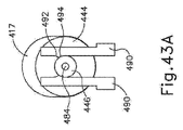
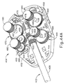
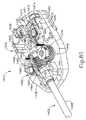
ベース(114)はロボットアームカート(40)のドック(72)と係合する装着板(116)を備える。板(116)は、明瞭にするために図12〜13で省略している点に留意されたい。図示していないが、ベース(114)は、1つ又は複数の電気接点及び/又はドック(72)の相補的な機構と電気通信を確立するように動作可能であるその他の機構を備えていてもよいことを理解されたい。シャフト支持構造体(122)はベース(114)から上方に延在し、(シャフトアセンブリ(160)が回転できるようにしたまま)シャフトアセンブリ(160)を支持する。ほんの一例であるが、シャフト支持構造体(122)は、ブッシング、ベアリング、及び/又は支持構造体(122)に対するシャフトアセンブリ(160)の回転を容易にするその他の機構を備えてよい。図10に見られるように、ベース(114)は、板(116)に対して回転可能な4個の駆動円盤(120)を更に備える。各円盤(120)は、一組の一体ピン(121)を備え、一体ピンはドック(72)の駆動要素の相補的陥凹(図示せず)と結合する。いくつかの変更例において、各対の一方のピン(121)は、対応する円盤(120)の回転軸のより近くにあり、ドック(72)の対応する駆動要素に対する円盤(120)の適正な角度配向を確保する。図11〜13にて最もよく見て取れるように、駆動シャフト(124、125、126、127)は各円盤(120)から上方に一体的に延在する。下記により詳細に説明するように、円盤(120)は、駆動シャフト(124、125、126、127)の回転を介して、シャフトアセンブリ(160)の独立した回転、関節セクション(170)の屈曲、及び発射ビーム(190)の平行移動を提供するように動作可能である。 The base (114) includes a mounting plate (116) that engages the dock (72) of the robot arm cart (40). Note that the plate (116) is omitted in FIGS. 12-13 for clarity. Although not shown, the base (114) includes one or more electrical contacts and / or other mechanisms operable to establish electrical communication with the complementary mechanism of the dock (72). I hope you understand. A shaft support structure (122) extends upward from the base (114) and supports the shaft assembly (160) (while allowing the shaft assembly (160) to rotate). By way of example only, shaft support structure (122) may include bushings, bearings, and / or other mechanisms that facilitate rotation of shaft assembly (160) relative to support structure (122). As seen in FIG. 10, the base (114) further comprises four drive disks (120) that are rotatable relative to the plate (116). Each disk (120) includes a set of integral pins (121) that couple with complementary recesses (not shown) in the drive element of the dock (72). In some variations, one pin (121) of each pair is closer to the axis of rotation of the corresponding disc (120) and the disc (120) is properly aligned with the corresponding drive element of the dock (72). Ensuring angular orientation. As best seen in FIGS. 11-13, the drive shafts (124, 125, 126, 127) extend integrally upward from each disk (120). As described in more detail below, the disc (120) is capable of independent rotation of the shaft assembly (160), bending of the articulation section (170) via rotation of the drive shaft (124, 125, 126, 127), And is operable to provide translation of the firing beam (190).
図11にて最もよく見て取れるように、第1ヘリカルギア(130)は駆動シャフト(124)に強固に固定され、対応する円盤(120)の回転により、第1ヘリカルギア(130)の回転がもたらされるようになっている。第1ヘリカルギア(130)は、回転結合部(164)に強固に固定されている第2ヘリカルギア(132)と噛合する。したがって、第1ヘリカルギア(130)の回転により、シャフトアセンブリ(160)の回転がもたらされる。第1軸を中心にした第1ヘリカルギア(130)の回転が、第1軸と直交する第2軸を中心にした第2ヘリカルギア(132)の回転に変換されていることを理解されたい。第2ヘリカルギア(132)の時計方向(CW)回転は、結果としてシャフトアセンブリ(160)のCW回転をもたらす。第2ヘリカルギア(132)の反時計方向(CCW)回転は、結果としてシャフトアセンブリ(160)のCCW回転をもたらす。シャフトアセンブリ(160)を回転させ得る他の好適な方法は、本明細書の教示を考慮することで当業者には明らかとなるであろう。 As best seen in FIG. 11, the first helical gear (130) is firmly fixed to the drive shaft (124), and rotation of the corresponding disk (120) results in rotation of the first helical gear (130). It is supposed to be. The first helical gear (130) meshes with the second helical gear (132) that is firmly fixed to the rotary coupling portion (164). Thus, rotation of the first helical gear (130) results in rotation of the shaft assembly (160). It should be understood that the rotation of the first helical gear (130) about the first axis is converted to the rotation of the second helical gear (132) about the second axis orthogonal to the first axis. . A clockwise (CW) rotation of the second helical gear (132) results in a CW rotation of the shaft assembly (160). Counterclockwise (CCW) rotation of the second helical gear (132) results in CCW rotation of the shaft assembly (160). Other suitable ways in which the shaft assembly (160) can be rotated will be apparent to those skilled in the art in view of the teachings herein.
図11〜12にて最もよく見て取れるように、スパーギア(134)は駆動シャフト(125)に強固に固定され、対応する円盤(120)の回転によって、スパーギア(134)の回転がもたらされるようになっている。スパーギア(134)は、ピニオンシャフト(138)に強固に固定されている第1スパーピニオン(136)と噛合する。ピニオンシャフト(138)はベース(116)によって支持され、かつベース(116)に対して自由に回転でき、その結果第1スパーピニオン(136)はアイドラとして回転可能である。したがって、第1スパーピニオン(136)がスパーギア(134)の回転に応じて回転することを理解されたい。第1スパーピニオン(136)も、駆動ブロック(142)に強固に固定されているラック(140)と噛合する。駆動ブロック(142)は発射ビーム結合部(166)に固定されている。したがって、第1スパーピニオン(136)の回転は、ラック(140)、駆動ブロック(142)、及び発射ビーム結合部(166)を経由して発射ビーム(190)の平行移動に変換される。上に注記したように、発射ビーム(190)はまず、発射ビーム(190)の遠位方向への移動の第1範囲の間に、組織の周囲でつかみ具(182、184)を合わせて、閉鎖するように操作可能であり、ついで発射ビーム(190)の遠位方向への移動の第1範囲の間につかみ具(182、184)の間に挟持された組織を切開するように操作可能である。したがって、組織は、駆動シャフトに対応する円盤(120)を介した駆動シャフト(125)の回転によって、挟持され、切開される。この回転が逆転される場合、発射ビーム(190)は近位に後退し、最終的には、つかみ具(182、184)が開いて組織が解放される。発射ビーム(190)が平行移動することができるその他の好適な方法は、本明細書の教示を考慮することで当業者には明らかとなるであろう。 As best seen in FIGS. 11-12, the spur gear (134) is firmly fixed to the drive shaft (125) so that rotation of the corresponding disk (120) causes rotation of the spur gear (134). ing. The spur gear (134) meshes with the first spar pinion (136) that is firmly fixed to the pinion shaft (138). The pinion shaft (138) is supported by the base (116) and can rotate freely with respect to the base (116) so that the first spar pinion (136) can rotate as an idler. Accordingly, it should be understood that the first spur pinion (136) rotates in response to the rotation of the spur gear (134). The first spar pinion (136) also meshes with the rack (140) that is firmly fixed to the drive block (142). The drive block (142) is fixed to the firing beam coupling (166). Accordingly, the rotation of the first spar pinion (136) is translated into a translation of the launch beam (190) via the rack (140), drive block (142), and launch beam coupling (166). As noted above, the firing beam (190) first aligns the grips (182, 184) around the tissue during the first range of distal movement of the firing beam (190), Operable to close and then operable to incise the tissue sandwiched between the grippers (182, 184) during a first range of distal movement of the firing beam (190) It is. Thus, the tissue is pinched and incised by rotation of the drive shaft (125) through the disk (120) corresponding to the drive shaft. If this rotation is reversed, the firing beam (190) retracts proximally and eventually the grippers (182, 184) are opened to release the tissue. Other suitable ways in which the firing beam (190) can translate will be apparent to those skilled in the art in view of the teachings herein.
関節制御に関しては、図11〜12に、第2スパーピニオン(144)が示されており、この第2スパーピニオン(144)は、対応する円盤(120)の回転によって、第2スパーピニオン(144)の回転がもたらされるように、駆動シャフト(126)に強固に固定されている。第2スパーピニオン(144)は、関節ビーム(174)に強固に固定されている左側ラック(146)と噛合する。関節ビーム(174)は、駆動シャフト(126)の回転に応じて遠位側又は近位側に平行移動することを理解されたい。同様に、図11及び13に、第3スパーピニオン(148)が示されており、第3スパーピニオン(148)は、対応する円盤(120)の回転によって第3スパーピニオン(148)の回転がもたらされるように、駆動シャフト(127)に強固に固定されている。第3スパーピニオン(148)は、関節ビーム(176)に強固に固定されている右側ラック(150)と噛合する。関節ビーム(176)は、駆動シャフト(127)の回転に応じて遠位側又は近位側に平行移動することを理解されたい。 Regarding the joint control, the second spar pinion (144) is shown in FIGS. 11 to 12, and the second spar pinion (144) is rotated by the corresponding disk (120) and the second spar pinion (144). ) Is firmly fixed to the drive shaft (126). The second spar pinion (144) meshes with the left rack (146) that is firmly fixed to the joint beam (174). It should be understood that the articulation beam (174) translates distally or proximally in response to rotation of the drive shaft (126). Similarly, the third spar pinion (148) is shown in FIGS. 11 and 13, and the third spar pinion (148) is rotated by the rotation of the corresponding disk (120). As provided, it is firmly fixed to the drive shaft (127). The third spar pinion (148) meshes with the right rack (150) that is firmly fixed to the joint beam (176). It should be understood that the articulation beam (176) translates distally or proximally in response to rotation of the drive shaft (127).
また、駆動シャフト(126、127)は、ビーム(174、176)の反対側への平行移動を提供するために、同時に同じ方向に回転してよいことも理解されたい。例えば、駆動シャフト(127)を時計方向に回転させてビーム(176)を遠位側に前進させながら、駆動シャフト(126)を時計方向に回転させてビーム(174)を近位側に後退させ、それによってエンドエフェクタ(180)を関節セクション(170)において左(L)に偏向させることが可能である。反対に、駆動シャフト(127)を反時計方向に回転させてビーム(176)を近位側に後退させながら、駆動シャフト(126)を反時計方向に回転させてビーム(174)を遠位側に前進させ、それによってエンドエフェクタ(180)を関節セクション(170)において左(R)に偏向させることが可能である。本明細書の教示を考慮することで、エンドエフェクタ(180が関節セクション(170)において関節運動することができるその他の好適な方法が、当業者に明らかであろう。ほんの一例であるが、関節制御は、米国公開特許第2012/0078243号(その開示内容を参照により本明細書に援用する。)、米国公開特許第2013/0023868号(その開示内容を参照により本明細書に援用する。)の教示の少なくとも一部に従って提供されてもよい。また、器械(100)のいくつかの変更例では、関節セクション(170)及び対応する制御部を単に欠いていてよいことも理解されたい。 It should also be understood that the drive shafts (126, 127) may rotate in the same direction at the same time to provide translation to the opposite side of the beams (174, 176). For example, while rotating the drive shaft (127) clockwise to advance the beam (176) distally, the drive shaft (126) is rotated clockwise to retract the beam (174) proximally. , Thereby allowing the end effector (180) to be deflected to the left (L) in the joint section (170). Conversely, while rotating the drive shaft (127) counterclockwise to retract the beam (176) proximally, the drive shaft (126) is rotated counterclockwise to move the beam (174) distally. The end effector (180) can be deflected to the left (R) in the joint section (170). In view of the teachings herein, other suitable ways in which the end effector (180 can articulate in the joint section (170) will be apparent to those skilled in the art. The control is disclosed in US Publication No. 2012/0078243 (the disclosure of which is incorporated herein by reference), US Publication No. 2013/0023868 (the disclosure of which is incorporated herein by reference). It should also be understood that some variations of the instrument (100) may simply lack the articulation section (170) and corresponding controls.
D.例示的な操作
ある例示的な使用では、アームカート(40)を使用し、トロカールを介してエンドエフェクタ(180)を患者内に挿入する。エンドエフェクタ(180)及びシャフトアセンブリ(160)の一部がトロカールを通って挿入される際には、関節セクション(170)は、実質的に直線状である。駆動シャフト(124)は、対応する円盤(120)と結合されたドック(72)内の駆動機構部を介して回転され、エンドエフェクタ(180)を組織に対して所望の角度配向に位置決めすることができる。ついで、駆動シャフト(126、126)が対応する円盤(120)と結合されたドック(72)内の駆動機構部を介して回転され、エンドエフェクタ(180)を患者内部の解剖学的構造体に対して所望の位置及び配向に位置決めするためにシャフトアセンブリ(160)の関節セクション(170)を枢動させるか、又は曲げることができる。続いて、駆動シャフト(125)を回転させ、動作の第1範囲を通って発射ビーム(190)を遠位側に前進させることによって、つかみ具(182、184)の間に解剖学的構造体の2層の組織を捕捉する。そのような組織の層は、患者内の解剖学的構造体を画定する、同一の自然管腔の一部(例えば、血管、胃腸管の一部分、生殖器系の一部分など)であってもよい。例えば、(器械(100)の使用前に血管を通過する流体経路が、エンドエフェクタ(180)などによって規定される長手方向軸に垂直であるように)、一方の組織層が、血管の上部を含み、他方の組織層が、その血管の同じ長さ範囲に沿った、血管の底部を含んでいてもよい。換言すれば、つかみ具(182、184)の長さは、血管の長さに対して垂直に(又は少なくとも概して横断方向に)配向されてもよい。上述したように、発射ビーム(190)が駆動シャフト(125)を回転させることによって遠位に作動されると、フランジ(192、196)はカム様に作用してつかみ具(182)をつかみ具(184)に向かって枢動させる。
D. Exemplary Operation In one exemplary use, an arm cart (40) is used to insert an end effector (180) into a patient via a trocar. When the end effector (180) and a portion of the shaft assembly (160) are inserted through the trocar, the articulation section (170) is substantially straight. The drive shaft (124) is rotated via a drive mechanism in the dock (72) associated with the corresponding disk (120) to position the end effector (180) in the desired angular orientation with respect to the tissue. Can do. The drive shaft (126, 126) is then rotated through a drive mechanism in the dock (72) associated with the corresponding disk (120) to bring the end effector (180) into the anatomical structure inside the patient. The articulation section (170) of the shaft assembly (160) can be pivoted or bent to position it in a desired position and orientation. Subsequently, the drive shaft (125) is rotated and the firing beam (190) is advanced distally through the first range of motion to thereby establish an anatomical structure between the grippers (182, 184). To capture two layers of tissue. Such a layer of tissue may be part of the same natural lumen (eg, blood vessel, part of the gastrointestinal tract, part of the genital system, etc.) that defines the anatomy within the patient. For example, one tissue layer may pass over the top of the blood vessel (so that the fluid path through the blood vessel prior to use of the instrument (100) is perpendicular to the longitudinal axis defined by the end effector (180), etc.). And the other tissue layer may include the bottom of the blood vessel along the same length range of the blood vessel. In other words, the length of the gripper (182, 184) may be oriented perpendicular (or at least generally transverse) to the length of the blood vessel. As described above, when the firing beam (190) is actuated distally by rotating the drive shaft (125), the flanges (192, 196) act like a cam to grip the grip (182). Pivot towards (184).
発射ビーム(190)は、駆動シャフト(125)の継続した回転に応じて、つかみ具(182、184)の間に組織層を捕捉した状態で、遠位側に前進を続ける。発射ビーム(190)が遠位側に前進を続けると、遠位ブレード(194)は、挟持された組織層を同時に切開し、それぞれの分離された下層部分と並置される、分離された上層部分がもたらされる。いくつかの変更例において、これにより、血管の長さに対して概して横断方向に切断された血管がもたらされる。つかみ具(182、184)の直上及び直下にフランジ(192、196)がそれぞれ存在することにより、つかみ具(182、184)を閉鎖した、しっかりと挟持する位置に保ちやすくなっていることを理解されたい。具体的には、フランジ(192、196)は、つかみ具(182、184)の間に大きな圧迫力を維持するのに役立ち得る。つかみ具(182、184)の間で切開した組織層部分を圧迫した状態で、外科医が、コントローラ(30)を介して(例えば、使用者入力アセンブリ(32)又はフットスイッチ(38)などを介して)対応する命令を入力すると、電極表面(186、187)は、バイポーラ高周波エネルギーで活性化される。いくつかの変更例において、電極(186、187)は、つかみ具(182、184)の電極表面(186、187)が共通の第1の極性で活性化される一方で、発射ビーム(190)が第1の極性と反対の第2の極性で活性化されるように、電源(102)と選択的に結合される。したがって、バイポーラ高周波電流は、切開された組織層部分の圧迫された領域を通って、発射ビーム(190)とつかみ具(182、184)の電極表面(186、187)との間を流れる。いくつかの他の変更例において、電極表面(186)が、一方の極性を有し、一方、電極表面(187)及び発射ビーム(190)の両方が、他方の極性を有する。いずれの変更例(少なくともいくつかの他の中でもとりわけ)においても、電源(102)によって送達されるバイポーラ高周波エネルギーは、最終的に、発射ビーム(190)の一方の側の組織層部分を1つに熱接合し、発射ビーム(190)の他方の側の組織層部分を1つに熱接合する。 The firing beam (190) continues to advance distally with the tissue layer captured between the grippers (182, 184) in response to continued rotation of the drive shaft (125). As the firing beam (190) continues to advance distally, the distal blade (194) simultaneously dissects the sandwiched tissue layer and is juxtaposed with each separated lower layer portion. Is brought about. In some variations, this results in a blood vessel that is cut generally transverse to the length of the blood vessel. It is understood that the presence of the flanges (192, 196) directly above and below the grips (182, 184) makes it easy to keep the grips (182, 184) in a closed and firm position. I want to be. Specifically, the flanges (192, 196) can help maintain a large compression force between the grippers (182, 184). With the tissue layer portion dissected between the grippers (182, 184) compressed, the surgeon may be via the controller (30) (eg, via the user input assembly (32) or foot switch (38)). When the corresponding command is input, the electrode surfaces (186, 187) are activated with bipolar high frequency energy. In some variations, the electrodes (186, 187) are activated by the firing beam (190) while the electrode surfaces (186, 187) of the gripper (182, 184) are activated with a common first polarity. Is selectively coupled to the power supply (102) such that is activated with a second polarity opposite to the first polarity. Thus, bipolar high frequency current flows through the compressed area of the dissected tissue layer portion between the firing beam (190) and the electrode surface (186, 187) of the gripper (182, 184). In some other variations, electrode surface (186) has one polarity, while both electrode surface (187) and firing beam (190) have the other polarity. In any variation (among other things, at least some other), the bipolar radio frequency energy delivered by the power source (102) will ultimately result in one tissue layer portion on one side of the firing beam (190). And the tissue layer portion on the other side of the firing beam (190) is thermally bonded together.
特定の状況下では、活性化された電極表面(186、187)によって生成される熱により、組織層部分内の膠原質を変性させることができ、この変性した膠原質は、つかみ具(182、184)によって提供される挟持圧と組み合わさって、組織層部分内に封着を形成することができる。したがって、解剖学的構造体を画定する自然管腔の切開された端部は、切開された端部が体液を漏出しないように、止血封鎖される。いくつかの変更例において、電極表面(186、187)は、発射ビーム(190)がまさに遠位側に平行移動を開始する前に、したがって組織がまさに切開される前に、バイポーラ高周波エネルギーで活性化される。器械(100)が操作可能であり、かつ操作することができるその他の好適な方法は、本明細書の教示を考慮することで当業者には明らかとなるであろう。 Under certain circumstances, the heat generated by the activated electrode surface (186, 187) can denature the collagen in the tissue layer portion, and this modified collagen is used as a grip (182, In combination with the clamping pressure provided by 184), a seal can be formed in the tissue layer portion. Accordingly, the incised end of the natural lumen defining the anatomical structure is hemostatically sealed so that the incised end does not leak body fluid. In some variations, the electrode surfaces (186, 187) are activated with bipolar radio frequency energy before the firing beam (190) just begins to translate distally and thus before the tissue is just dissected. It becomes. Other suitable ways in which the instrument (100) can be operated and can be operated will be apparent to those skilled in the art in view of the teachings herein.
III.平行移動する駆動アセンブリを備える例示的な代替的電気手術器械
図14〜15に例示的な代替的電気手術器械(200)を示す。この例の器械(200)は、器械(200)がシャフトアセンブリ(202)、関節セクション(204)、及びエンドエフェクタ(206)を有し、それらが上述のシャフトアセンブリ(160)、関節セクション(170)、及びエンドエフェクタ(180)と実質的に同一である、という点で上述の器械(100)と実質的に類似している。また、この例の器械(200)は、インターフェースアセンブリ(210)を介してロボットアームカート(40)のドック(72)と結合するように動作可能である。しかしながら、この例のインターフェースアセンブリ(210)は、上に説明したインターフェースアセンブリ(110)とは異なる。いくつかの例においては、インターフェースアセンブリ(210)から取り外し可能なシャフトアセンブリ(202)を提供することが経済的に望ましい場合がある。例えば、シャフトアセンブリ(202)は外科手技の後にインターフェースアセンブリ(210)から取り外しでき、シャフトアセンブリ(202)を廃棄し得る一方で、インターフェースアセンブリ(210)を殺菌し、別の外科手技に再使用し得るようになっている。したがって、シャフトアセンブリ(202)及びインターフェースアセンブリ(210)は、インターフェースアセンブリ(210)の駆動アセンブリ(240、250、260、270)が、シャフトアセンブリ(202)に取り外し可能に係合するように、シャフトアセンブリ(202)に対して平行移動させることができ、かつシャフトアセンブリ(202)をインターフェースアセンブリ(210)に挿入し、かつ/又はそれから取り外すことができるような機構を備える。下記の例には、器械(200)に容易に導入できる平行移動機構部のいくつかの、単に例示的ないくつかの変更例が含まれる。
III. Exemplary Alternative Electrosurgical Instrument with Translational Drive Assembly FIGS. 14-15 illustrate an exemplary alternative electrosurgical instrument (200). In this example instrument (200), the instrument (200) has a shaft assembly (202), a joint section (204), and an end effector (206), which are the shaft assembly (160), joint section (170) described above. ), And substantially the same as the end effector (180), in that it is substantially similar to the instrument (100) described above. The example instrument (200) is also operable to couple with the dock (72) of the robot arm cart (40) via the interface assembly (210). However, the interface assembly (210) in this example is different from the interface assembly (110) described above. In some examples, it may be economically desirable to provide a shaft assembly (202) that is removable from the interface assembly (210). For example, the shaft assembly (202) can be removed from the interface assembly (210) after a surgical procedure and the shaft assembly (202) can be discarded while the interface assembly (210) is sterilized and reused in another surgical procedure. To get. Thus, the shaft assembly (202) and the interface assembly (210) are such that the drive assembly (240, 250, 260, 270) of the interface assembly (210) removably engages the shaft assembly (202). A mechanism is provided that can be translated relative to the assembly (202) and that the shaft assembly (202) can be inserted into and / or removed from the interface assembly (210). The examples below include some merely exemplary modifications of some of the translation mechanisms that can be easily introduced into the instrument (200).
A.側部回転ノブを備える例示的な平行移動する駆動アセンブリ
図16にシャフトアセンブリ(202)をより詳細に示す。シャフトアセンブリ(202)は、外側シャフト(208)、内側シャフト(209)、ヘリカルギア(220)、及びカラー(222、225、230)を備える。ヘリカルギア(220)は、外側シャフト(208)の近位部分を中心に配置され、かつインターフェースアセンブリ(210)に対して外側シャフト(208)を回転させるように操作可能である。外側シャフト(208)の遠位部分は、関節セクション(204)及びエンドエフェクタ(206)と結合され、ヘリカルギア(220)による外側シャフト(204)の回転によって、関節セクション(204)及びエンドエフェクタ(206)が回転するようになっている。内側シャフト(209)は、外側シャフト(204)から近位側に延在し、外側シャフト(204)の内部に、摺動可能かつ同軸に受容されている。カラー(222、225、230)は内側シャフト(209)を中心に配置される。第1カラー(222)は、ヘリカルギア(220)に対して近位側にあり、かつ遠位フランジ(221)、中央部(223)、及び近位フランジ(224)を含む。中央部(223)は、遠位フランジ(221)と近位フランジ(224)を接続し、かつ遠位フランジ(221)及び近位フランジ(224)よりも小さい外径を有する。第1カラー(222)は内側シャフト(209)の近位部分としっかりと結合されている。内側シャフト(209)の遠位部分は発射ビーム(190)と結合されている。したがって、第1カラー(222)の平行移動によって、内側シャフト(209)及び発射ビーム(190)が外側シャフト(208)に対して平行移動する。
A. Exemplary Translating Drive Assembly with Side Rotation Knob FIG. 16 shows the shaft assembly (202) in more detail. The shaft assembly (202) includes an outer shaft (208), an inner shaft (209), a helical gear (220), and a collar (222, 225, 230). Helical gear (220) is disposed about the proximal portion of outer shaft (208) and is operable to rotate outer shaft (208) relative to interface assembly (210). The distal portion of the outer shaft (208) is coupled with the joint section (204) and the end effector (206), and rotation of the outer shaft (204) by the helical gear (220) causes the joint section (204) and the end effector ( 206) is adapted to rotate. The inner shaft (209) extends proximally from the outer shaft (204) and is slidably and coaxially received within the outer shaft (204). The collars (222, 225, 230) are arranged around the inner shaft (209). The first collar (222) is proximal to the helical gear (220) and includes a distal flange (221), a central portion (223), and a proximal flange (224). The central portion (223) connects the distal flange (221) and the proximal flange (224) and has a smaller outer diameter than the distal flange (221) and the proximal flange (224). The first collar (222) is securely coupled to the proximal portion of the inner shaft (209). The distal portion of the inner shaft (209) is coupled with the firing beam (190). Thus, translation of the first collar (222) translates the inner shaft (209) and the firing beam (190) relative to the outer shaft (208).
第2カラー(225)は、第1カラー(222)に対して近位側にあり、かつ遠位フランジ(226)、中央部(227)、及び近位フランジ(228)を含む。中央部(227)は、遠位フランジ(226)と近位フランジ(228)と接続し、かつ遠位フランジ(226)及び近位フランジ(228)よりも小さい外径を有する。第3カラー(230)は、第2カラー(225)に対して近位側にあり、かつ遠位フランジ(229)、中央部(231)、及び近位フランジ(232)を有する。中央部(231)は、遠位フランジ(229)と近位フランジ(232)と接続し、かつ遠位フランジ(229)及び近位フランジ(232)よりも小さい外径を有する。第2及び第3カラー(225、230)は内側シャフト(209)に対して平行移動可能である。第2及び第3カラー(225、230)は、内側シャフト(209)内部に延在する、それぞれの関節ビーム(174、176)とそれぞれ結合されていて、第2及び第3カラー(225、230)の平行移動によって、関節ビーム(174、176)が平行移動するようになっている。したがって、カラー(225、230)の平行移動により、関節セクション(204)における関節運動がもたらされる。 The second collar (225) is proximal to the first collar (222) and includes a distal flange (226), a central portion (227), and a proximal flange (228). The central portion (227) connects the distal flange (226) and the proximal flange (228) and has a smaller outer diameter than the distal flange (226) and the proximal flange (228). The third collar (230) is proximal to the second collar (225) and has a distal flange (229), a central portion (231), and a proximal flange (232). The central portion (231) connects the distal flange (229) and the proximal flange (232) and has a smaller outer diameter than the distal flange (229) and the proximal flange (232). The second and third collars (225, 230) are translatable relative to the inner shaft (209). The second and third collars (225, 230) are coupled to respective articulation beams (174, 176) that extend inside the inner shaft (209), respectively, and the second and third collars (225, 230). ) Translates the joint beams (174, 176). Thus, translation of the collar (225, 230) results in articulation in the joint section (204).
図17にシャフトアセンブリ(202)と取り外し可能に結合可能なインターフェースアセンブリ(210)のベース(214)を示す。インターフェースアセンブリ(210)のベース(214)は、装着板(216)上に配置された駆動アセンブリ(240、250、260、270)及び平行移動アセンブリ(280)を備える。第1駆動アセンブリ(240)は、図18に示すように、ヘリカルギア(248)、駆動シャフト(246)、及び円盤(244)を含む。ヘリカルギア(248)は、円盤(244)上に搭載された駆動シャフト(246)上に搭載される。駆動シャフト(246)は、円盤(244)が装着板(216)の下方に配置され、かつヘリカルギア(248)が装着板(216)の上方に配置されるように、装着板(216)の開口部を通って延在する。ヘリカルギア(248)は、シャフトアセンブリ(202)のヘリカルギア(220)と係合するように構成される。円盤(244)は、円盤(244)を回転させる、ドック(72)内の駆動機構部と結合される。円盤(244)の回転により、駆動シャフト(246)、ヘリカルギア(248)、及びヘリカルギア(220)を介して、シャフトアセンブリ(202)の外側シャフト(208)が回転する。弾性部材(242)は円盤(244)と結合され、装着板(216)内部の円盤(244)をシャフトアセンブリ(202)に向かって横方向に弾性的に付勢する。 FIG. 17 shows the base (214) of the interface assembly (210) removably connectable to the shaft assembly (202). The base (214) of the interface assembly (210) includes a drive assembly (240, 250, 260, 270) and a translation assembly (280) disposed on the mounting plate (216). The first drive assembly (240) includes a helical gear (248), a drive shaft (246), and a disk (244) as shown in FIG. The helical gear (248) is mounted on a drive shaft (246) mounted on a disk (244). The drive shaft (246) is arranged on the mounting plate (216) such that the disk (244) is disposed below the mounting plate (216) and the helical gear (248) is disposed above the mounting plate (216). Extends through the opening. Helical gear (248) is configured to engage with helical gear (220) of shaft assembly (202). The disc (244) is coupled to a drive mechanism in the dock (72) that rotates the disc (244). The rotation of the disk (244) rotates the outer shaft (208) of the shaft assembly (202) via the drive shaft (246), helical gear (248), and helical gear (220). The elastic member (242) is coupled to the disk (244) and elastically biases the disk (244) inside the mounting plate (216) laterally toward the shaft assembly (202).
第2駆動アセンブリ(250)は、図19に示すように、一対のラック(251、257)、ピニオンギア(258)、駆動シャフト(256)、及び円盤(254)を含む。第1ラック(251)は、第1の長手方向列の歯(253)、歯(253)から横断方向に延在する第1アーム(255)、及び第1アーム(255)に結合した第1係合機構部(255)を備える。第1係合機構部(255)は湾曲していて、シャフトアセンブリ(202)の第2カラー(225)の中央部(227)に対応するように寸法決めされ、その結果第1係合機構部(255)は中央部(227)の一部分と係合し、かつ中央部(227)の一部分を包み込むように構成される。第1係合機構部(255)が中央部(227)と係合されると、第2カラー(225)の遠位フランジ(226)及び近位フランジ(228)が第1係合機構部(255)を超えて延在することになり、第2カラー(255)に対する第1係合機構部(255)の長手方向位置が維持される。第1係合機構部(255)は、第2カラー(225)が第1係合機構部(255)に対して回転可能であるように、第2カラー(225)と結合される。第2ラック(257)は、第2の長手方向列の歯(259)、歯(259)から横断方向に延在する第2アーム(261)、及び第2アーム(261)と結合した第2係合機構部(263)を備える。第2アーム(261)は第1係合機構部(255)及び第2係合機構部(263)と長手方向に整列するように延在する。第2係合機構部(263)は湾曲していて、シャフトアセンブリ(202)の第3カラー(230)の中央部(231)に対応するように寸法決めされ、その結果第2係合機構部(263)は中央部(231)の一部分と係合し、かつ中央部(231)の一部分を包み込むように構成される。第2係合機構部(263)が中央部(231)と係合されると、第3カラー(230)の遠位フランジ(229)及び近位フランジ(232)が第2係合機構部(263)を超えて延在することになり、第3カラー(230)に対する第2係合機構部(263)の長手方向位置が維持される。第2係合機構部(263)は、第3カラー(230)が第2係合機構部(263)に対して回転可能であるように、第3カラー(230)と結合される。ラック(251、257)の歯(253、259)の各列は駆動シャフト(256)上に搭載されたギア(258)と係合する。駆動シャフト(256)は、円盤(254)が装着板(216)の下方に配置され、かつギア(258)が装着板(216)の上方に配置されるように、円盤(254)から装着板(216)の開口部を通って上方に延在する。円盤(254)は、円盤(254)を回転させる、ドック(72)内の駆動機構部と結合される。円盤(254)の回転は、それによって駆動シャフト(256)及びギア(258)を回転させる。ギア(258)の回転はラック(251、257)を同時に反対方向に平行移動させ、それによって第2及び第3カラー(225、230)を反対方向に平行移動させる。したがって、関節ビーム(174、176)は第2及び第3カラー(225、230)によって平行移動させられ、エンドエフェクタ(206)をシャフトアセンブリ(202)から横方向に偏向させる。弾性部材(252)は円盤(254)と結合され、装着板(216)内部の円盤(254)をシャフトアセンブリ(202)に向かって横方向に弾性的に付勢する。 As shown in FIG. 19, the second drive assembly (250) includes a pair of racks (251, 257), a pinion gear (258), a drive shaft (256), and a disk (254). The first rack (251) is coupled to a first longitudinal row of teeth (253), a first arm (255) extending transversely from the teeth (253), and a first arm (255). An engagement mechanism (255) is provided. The first engagement mechanism (255) is curved and dimensioned to correspond to the central portion (227) of the second collar (225) of the shaft assembly (202), so that the first engagement mechanism (255) is configured to engage a portion of the central portion (227) and wrap around a portion of the central portion (227). When the first engagement mechanism (255) is engaged with the central portion (227), the distal flange (226) and the proximal flange (228) of the second collar (225) are moved to the first engagement mechanism ( 255) and the longitudinal position of the first engagement mechanism portion (255) relative to the second collar (255) is maintained. The first engagement mechanism (255) is coupled with the second collar (225) such that the second collar (225) is rotatable relative to the first engagement mechanism (255). The second rack (257) is coupled to the second longitudinal row of teeth (259), a second arm (261) extending transversely from the teeth (259), and a second arm (261). An engagement mechanism (263) is provided. The second arm (261) extends to align with the first engagement mechanism (255) and the second engagement mechanism (263) in the longitudinal direction. The second engagement mechanism portion (263) is curved and dimensioned to correspond to the central portion (231) of the third collar (230) of the shaft assembly (202), so that the second engagement mechanism portion. (263) is configured to engage a portion of the central portion (231) and wrap around a portion of the central portion (231). When the second engagement mechanism part (263) is engaged with the central part (231), the distal flange (229) and the proximal flange (232) of the third collar (230) are moved to the second engagement mechanism part ( 263) and the longitudinal position of the second engagement mechanism portion (263) relative to the third collar (230) is maintained. The second engagement mechanism (263) is coupled with the third collar (230) such that the third collar (230) is rotatable relative to the second engagement mechanism (263). Each row of teeth (253, 259) of the rack (251, 257) engages a gear (258) mounted on the drive shaft (256). The drive shaft (256) is mounted from the disk (254) to the mounting plate such that the disk (254) is positioned below the mounting plate (216) and the gear (258) is positioned above the mounting plate (216). (216) extends upward through the opening. The disc (254) is coupled to a drive mechanism in the dock (72) that rotates the disc (254). The rotation of the disk (254) thereby causes the drive shaft (256) and gear (258) to rotate. The rotation of the gear (258) simultaneously translates the racks (251, 257) in opposite directions, thereby translating the second and third collars (225, 230) in opposite directions. Accordingly, the joint beams (174, 176) are translated by the second and third collars (225, 230) to deflect the end effector (206) laterally from the shaft assembly (202). The elastic member (252) is coupled to the disk (254) and elastically biases the disk (254) inside the mounting plate (216) laterally toward the shaft assembly (202).
第3駆動アセンブリ(260)は、図20に示すように、円盤(264)上に搭載された駆動シャフト(266)上に搭載された偏心カム(267)を備える。駆動シャフト(266)は、円盤(264)が装着板(216)の下方に配置され、かつ偏心カム(267)が装着板(216)の上方に配置されるように、装着板(216)の開口部を通って延在する。アーム(268)の細長い開口部は偏心カム(267)を中心に配置される。アーム(268)は、アーム(268)から横方向に延在する係合機構部(269)を備える。係合機構部(269)は湾曲したプロファイルを有し、シャフトアセンブリ(202)の第1カラー(222)の中央部(223)に対応するように寸法決めされ、その結果係合機構部(269)は中央部(223)の一部分と係合し、かつ中央部(223)の一部分を包み込むように構成される。係合機構部(269)が中央部(223)と係合されると、第1カラー(222)の遠位フランジ(221)及び近位フランジ(224)が係合機構部(269)を超えて延在することになり、第1カラー(222)に対する係合機構部(269)の長手方向位置が維持される。係合機構部(269)は、第1カラー(222)が係合機構部(269)に対して回転可能であるように、第1カラー(222)と結合される。円盤(264)は、円盤(264)を回転させる、ドック(72)内の駆動機構部と結合され、円盤(264)の回転は、次いで駆動シャフト(266)及び偏心カム(267)の回転を引き起こす。カム(267)のオフセンター回転はアーム(268)を平行移動させ、それにより第1カラー(222)を平行移動させる。したがって、発射ビーム(190)は第1カラー(222)によって平行移動させられる。弾性部材(262)は円盤(264)と結合され、装着板(216)内部の円盤(264)をシャフトアセンブリ(202)に向かって横方向に弾性的に付勢する。 The third drive assembly (260) includes an eccentric cam (267) mounted on a drive shaft (266) mounted on a disk (264), as shown in FIG. The drive shaft (266) is mounted on the mounting plate (216) such that the disk (264) is disposed below the mounting plate (216) and the eccentric cam (267) is disposed above the mounting plate (216). Extends through the opening. The elongated opening of arm (268) is centered about eccentric cam (267). The arm (268) includes an engagement mechanism (269) extending laterally from the arm (268). The engagement mechanism (269) has a curved profile and is sized to correspond to the central portion (223) of the first collar (222) of the shaft assembly (202), so that the engagement mechanism (269) ) Is configured to engage a portion of the central portion (223) and wrap around a portion of the central portion (223). When the engagement mechanism (269) is engaged with the central portion (223), the distal flange (221) and the proximal flange (224) of the first collar (222) exceed the engagement mechanism (269). Thus, the longitudinal position of the engagement mechanism portion (269) with respect to the first collar (222) is maintained. The engagement mechanism (269) is coupled with the first collar (222) such that the first collar (222) is rotatable relative to the engagement mechanism (269). The disk (264) is coupled with a drive mechanism in the dock (72) that rotates the disk (264), which in turn rotates the drive shaft (266) and eccentric cam (267). cause. Off-center rotation of the cam (267) translates the arm (268), thereby translating the first collar (222). Thus, the firing beam (190) is translated by the first collar (222). The elastic member (262) is coupled to the disk (264) and elastically biases the disk (264) inside the mounting plate (216) laterally toward the shaft assembly (202).
第4駆動アセンブリ(270)は、図21に示すように、円盤(274)及び円盤(274)から上方に延在する駆動シャフト(276)を含む。駆動シャフト(276)は装着板(216)の開口部の内部に位置決めされるように構成される。この例では、第4駆動アセンブリ(270)はアイドル状態を保ち、かつ平行移動アセンブリ(280)向けの枢軸支持を提供する。いくつかの例では、第4駆動アセンブリ(270)が、上記のインターフェースアセンブリ(110)と同様に、関節ビーム(174、176)を平行移動させるように構成されるよう、円盤(274)は、ドック(72)内の駆動機構部と結合される。弾性部材(272)は円盤(274)と結合され、装着板(216)内部の円盤(274)を弾性的に付勢する。 The fourth drive assembly (270) includes a disk (274) and a drive shaft (276) extending upward from the disk (274), as shown in FIG. The drive shaft (276) is configured to be positioned inside the opening of the mounting plate (216). In this example, the fourth drive assembly (270) remains idle and provides pivot support for the translation assembly (280). In some examples, the disk (274) is configured such that the fourth drive assembly (270) is configured to translate the joint beams (174, 176), similar to the interface assembly (110) described above. Coupled with the drive mechanism in the dock (72). The elastic member (272) is coupled to the disk (274) and elastically biases the disk (274) inside the mounting plate (216).
図22に装着板(216)の底面図を示す。装着板(216)の底面は、円盤(244、254、264、274)を収容するために、装着板(216)の内部に延在する陥凹(213)を備える。駆動アセンブリ(240、250)の弾性部材(242、252)は陥凹(213)の第1壁(215)に対して位置決めされる。駆動アセンブリ(260、270)の弾性部材(262、272)は陥凹(213)の反対側の壁(217)に対して位置決めされる。弾性部材(242、252、262、272)は、それによって円盤(244、254、264、274)を陥凹(213)の内部で内向きに付勢する。円盤(244、254、264、274)は、陥凹(213)の内部で内向きに、かつ/又は外向きに平行移動するように構成される。装着板(216)は、円盤(244、254、264、274)が平行移動されるときに駆動シャフト(246、256、266、276)が開口部(212)内部で平行移動することができるように開口部(212)を備える。 FIG. 22 shows a bottom view of the mounting plate (216). The bottom surface of the mounting plate (216) includes a recess (213) extending inside the mounting plate (216) to accommodate the disks (244, 254, 264, 274). The elastic members (242, 252) of the drive assembly (240, 250) are positioned relative to the first wall (215) of the recess (213). The elastic members (262, 272) of the drive assembly (260, 270) are positioned relative to the wall (217) opposite the recess (213). The elastic members (242, 252, 262, 272) thereby bias the disks (244, 254, 264, 274) inwardly within the recess (213). The disks (244, 254, 264, 274) are configured to translate inwardly and / or outwardly within the recess (213). The mounting plate (216) allows the drive shaft (246, 256, 266, 276) to translate within the opening (212) when the disks (244, 254, 264, 274) are translated. Is provided with an opening (212).
図23に平行移動アセンブリ(280)をより詳細に示す。平行移動アセンブリ(280)は、回転ノブアセンブリ(282)、第1連結部(292)、第2連結部(288)、第3連結部(298)、及び第4連結部(299)を含む。回転ノブアセンブリ(282)は、図24に示すように、回転ノブ(281)から延在する、ねじ切りされたねじ(283)を有する回転ノブ(281)を含む。ねじ切りされたナット(285)はねじ(283)を中心に配置され、かつねじ(283)に対応したねじ山を備え、ノブ(281)によるねじ(283)の回転により、ねじ切りされたナット(285)が平行移動するようになっている。ピン(286、287)はねじ切りされたナット(285)の対向する表面上から外側に延在する。第1連結部(292)は、図25に示すように、第1表面(295)、第1表面(295)から上方に延在する第2表面(297)、及び第2表面(297)から延在する第3表面(293)を備え、第3表面(293)と第1表面(295)とは実質的に平行である。開口部(294)は、第3表面(293)上に備えられ、ねじ切りされたナット(285)のピン(286)を受容し、その結果第1連結部(292)はねじ切りされたナット(285)に対して枢動可能である。別の開口部(296)が第1表面(295)上に備えられる。第2連結部(288)は、図26に示すように、開口部(291、289)を備える。開口部(291)は、ねじ切りされたナット(285)のピン(287)を受容するように構成され、その結果第2連結部(288)はねじ切りされたナット(285)に対して枢動可能である。 FIG. 23 shows the translation assembly (280) in more detail. The translation assembly (280) includes a rotary knob assembly (282), a first connection part (292), a second connection part (288), a third connection part (298), and a fourth connection part (299). The rotation knob assembly (282) includes a rotation knob (281) having a threaded screw (283) extending from the rotation knob (281), as shown in FIG. The threaded nut (285) is centered about the screw (283) and has a thread corresponding to the screw (283), and the threaded nut (285) by rotation of the screw (283) by the knob (281). ) Will move in parallel. Pins (286, 287) extend outwardly from above the opposing surface of the threaded nut (285). As shown in FIG. 25, the first connecting portion (292) includes a first surface (295), a second surface (297) extending upward from the first surface (295), and a second surface (297). An extended third surface (293) is provided, and the third surface (293) and the first surface (295) are substantially parallel. An opening (294) is provided on the third surface (293) to receive the pin (286) of the threaded nut (285) so that the first connection (292) is threaded nut (285). ). Another opening (296) is provided on the first surface (295). As shown in FIG. 26, the second connecting portion (288) includes openings (291, 289). The opening (291) is configured to receive a pin (287) of a threaded nut (285) so that the second connection (288) is pivotable relative to the threaded nut (285). It is.
第3連結部(298)は、図27に示すように、第3連結部(298)の両末端部に細長い開口部(233、236)を備える。開口部(236)は、第1駆動アセンブリ(240)の駆動シャフト(246)を、駆動シャフト(246)が開口部(236)の内部で平行移動可能なように受容するように構成されている。開口部(233)は、第4駆動アセンブリ(270)の駆動シャフト(276)を、駆動シャフト(276)が開口部(233)の内部で平行移動可能なように受容するように構成されている。開口部(234)は第3連結部(298)の中央部内に備えられる。ピン(235)は第3連結部(298)から延在して、第1連結部(292)の開口部(296)内に受容され、その結果第3連結部(298)は第1連結部(292)に対して枢動可能である。第4連結部(299)は、図28に示すように、第4連結部(299)の両末端部に細長い開口部(237、243)を備える。開口部(237)は、第3駆動アセンブリ(260)の駆動シャフト(266)を、駆動シャフト(266)が開口部(237)の内部で平行移動可能なように受容するように構成されている。開口部(243)は、第2駆動アセンブリ(250)の駆動シャフト(256)を、駆動シャフト(256)が開口部(243)の内部で平行移動可能なように受容するように構成されている。開口部(238)は第4連結部(299)の中央部内に備えられる。第4連結部(299)の開口部(238)は第3連結部(298)の開口部(234)に隣接して位置決めされる。ピン(図示せず)は、第3及び第4連結部(298、299)を装着板(216)に取り付けるように、開口部(238、234)を通って設置され、その結果第4連結部(299)は第3連結部(298)に対して枢動可能であるが、第3及び第4連結部(298、299)の長手方向位置及び横方向位置は装着板(216)に対して固定される。ピン(239)は第4連結部(299)から延在し、かつ第2連結部(288)の開口部(289)内に受容され、その結果第4連結部(299)は第2連結部(288)に対して枢動可能である。 As shown in FIG. 27, the third connecting portion (298) includes elongated openings (233, 236) at both end portions of the third connecting portion (298). The opening (236) is configured to receive the drive shaft (246) of the first drive assembly (240) such that the drive shaft (246) is translatable within the opening (236). . The opening (233) is configured to receive the drive shaft (276) of the fourth drive assembly (270) such that the drive shaft (276) is translatable within the opening (233). . The opening (234) is provided in the central part of the third connecting part (298). The pin (235) extends from the third connecting part (298) and is received in the opening (296) of the first connecting part (292), so that the third connecting part (298) is received by the first connecting part. Pivotable with respect to (292). As shown in FIG. 28, the fourth connecting portion (299) includes elongated openings (237, 243) at both end portions of the fourth connecting portion (299). The opening (237) is configured to receive the drive shaft (266) of the third drive assembly (260) such that the drive shaft (266) is translatable within the opening (237). . The opening (243) is configured to receive the drive shaft (256) of the second drive assembly (250) such that the drive shaft (256) is translatable within the opening (243). . The opening (238) is provided in the central part of the fourth connecting part (299). The opening (238) of the fourth connecting part (299) is positioned adjacent to the opening (234) of the third connecting part (298). A pin (not shown) is installed through the openings (238, 234) to attach the third and fourth coupling parts (298, 299) to the mounting plate (216), and as a result, the fourth coupling part. (299) is pivotable with respect to the third connecting part (298), but the longitudinal and lateral positions of the third and fourth connecting parts (298, 299) are relative to the mounting plate (216). Fixed. The pin (239) extends from the fourth connecting part (299) and is received in the opening (289) of the second connecting part (288), so that the fourth connecting part (299) is the second connecting part. Pivotable with respect to (288).
したがって、平行移動アセンブリ(280)は、図29A〜30Bに示すように、インターフェースアセンブリ(210)内部で駆動アセンブリ(240、250、260、270)を横方向に平行移動させて、シャフトアセンブリ(202)に対する係合解除、及び係合を行わせるように操作可能である。図29Aに初期位置の平行移動アセンブリ(280)を示す。この位置において、ねじ切りされたナット(285)はねじ(283)上で内側位置にあり、かつ駆動アセンブリ(240、250、260、270)は外側位置にあり、その結果駆動アセンブリ(240、250、260、270)は、図30Aに示すように、シャフトアセンブリ(202)から係合解除されている。回転ノブ(281)は、図29Bに示すように、続いて回転され、ねじ切りされたナット(285)をねじ(283)に沿ってねじ(283)の末端部に向かって平行移動させる。ねじ切りされたナット(285)がねじ(283)の末端部に向かって平行移動すると、第1及び第2連結部(292、288)は、互いから離れる方向に枢動され、第3及び第4連結部(298、299)を枢動させる。これにより、第3及び第4連結部(298、299)の開口部(233、236、237、243)は、インターフェースアセンブリ(210)内で内側に平行移動し、駆動アセンブリ(240、250、260、270)を、インターフェースアセンブリ(210)内で内側に平行移動させて、図30Bに示すように、シャフトアセンブリ(202)と係合させる。したがって、第1駆動アセンブリ(240)のヘリカルギア(248)は、シャフトアセンブリ(202)のヘリカルギア(220)と係合し、第2駆動アセンブリ(250)の係合機構部(255、263)は、シャフトアセンブリ(202)のそれぞれの第2及び第3カラー(225、230)と係合し、かつ第3駆動アセンブリ(260)の係合機構部(269)は、シャフトアセンブリ(202)の第1カラー(222)と係合する。駆動アセンブリ(240、250、260、270)の弾性部材(242、252、262、272)は、インターフェースアセンブリ(210)内で駆動アセンブリ(240、250、260、270)が内側に平行移動しやすくなるように、付勢されている。 Accordingly, the translation assembly (280) translates the drive assembly (240, 250, 260, 270) laterally within the interface assembly (210) to provide a shaft assembly (202) as shown in FIGS. 29A-30B. ) Can be operated to release and engage. FIG. 29A shows the initial translation assembly (280). In this position, the threaded nut (285) is in the inner position on the screw (283) and the drive assembly (240, 250, 260, 270) is in the outer position, so that the drive assembly (240, 250, 260, 270) are disengaged from the shaft assembly (202) as shown in FIG. 30A. The rotation knob (281) is subsequently rotated as shown in FIG. 29B to translate the threaded nut (285) along the screw (283) toward the distal end of the screw (283). As the threaded nut (285) translates toward the distal end of the screw (283), the first and second coupling portions (292, 288) are pivoted away from each other, and the third and fourth The connecting part (298, 299) is pivoted. As a result, the openings (233, 236, 237, 243) of the third and fourth coupling parts (298, 299) are translated inwardly within the interface assembly (210), and the drive assemblies (240, 250, 260). 270) is translated inward within the interface assembly (210) to engage the shaft assembly (202) as shown in FIG. 30B. Accordingly, the helical gear (248) of the first drive assembly (240) engages with the helical gear (220) of the shaft assembly (202), and the engagement mechanism (255, 263) of the second drive assembly (250). Engages the respective second and third collars (225, 230) of the shaft assembly (202), and the engagement mechanism (269) of the third drive assembly (260) is coupled to the shaft assembly (202). Engage with the first collar (222). The elastic members (242, 252, 262, 272) of the drive assembly (240, 250, 260, 270) facilitate inward translation of the drive assembly (240, 250, 260, 270) within the interface assembly (210). It is energized to be.
シャフトアセンブリ(202)から係合解除するためには、回転ノブ(281)を反対方向に回転させて連結部(288、292、298、299)を図29A及び30Aに示した初期位置に戻すように平行移動させることで、駆動アセンブリ(240、250、260、270)をインターフェースアセンブリ(210)内部で外側に平行移動させて、シャフトアセンブリ(202)から係合解除させ得る。駆動アセンブリ(240、250、260、270)の初期位置へ戻る平行移動により、装着板(216)内部で弾性部材(242、252、262、272)が圧縮される。 To disengage from the shaft assembly (202), the rotary knob (281) is rotated in the opposite direction to return the coupling (288, 292, 298, 299) to the initial position shown in FIGS. 29A and 30A. Can translate the drive assembly (240, 250, 260, 270) outwardly within the interface assembly (210) and disengage from the shaft assembly (202). Due to the translation back to the initial position of the drive assembly (240, 250, 260, 270), the elastic members (242, 252, 262, 272) are compressed inside the mounting plate (216).
1つの例示的な使用において、平行移動アセンブリ(280)は、駆動アセンブリ(240、250、260、270)がインターフェースアセンブリ(210)内部で外側位置にあるように、図30Aの初期位置に位置決めされる。シャフトアセンブリ(202)は、インターフェースアセンブリ(210)の近位端を通って遠位に挿入され得る。また、シャフトアセンブリ(202)を、ハウジングを取り外した状態でインターフェースアセンブリ(210)の上方に配置し、インターフェースアセンブリ(210)の中に横断して挿入してもよい。回転ノブ(281)は、図29Bに示すように、続いて回転され、ねじ切りされたナット(285)をねじ(283)に沿ってねじ(283)の末端部に向かって平行移動させる。ねじ切りされたナット(285)が平行移動すると、第1及び第2連結部(292、288)は、互いから離れる方向に枢動され、第3及び第4連結部(298、299)を枢動させる。これにより、第3及び第4連結部(298、299)の開口部(233、236、237、243)は、インターフェースアセンブリ(210)内で内側に平行移動し、駆動アセンブリ(240、250、260、270)を、インターフェースアセンブリ(210)内で内側に平行移動させて、図30Bに示すように、シャフトアセンブリ(202)と係合させる。したがって、第1駆動アセンブリ(240)のヘリカルギア(248)は、シャフトアセンブリ(202)のヘリカルギア(220)と係合し、第2駆動アセンブリ(250)の係合機構部(255、263)は、シャフトアセンブリ(202)のそれぞれの第2及び第3カラー(225、230)と係合し、かつ第3駆動アセンブリ(260)の係合機構部(269)は、シャフトアセンブリ(202)の第1カラー(222)と係合する。駆動アセンブリ(240、250、260、270)の弾性部材(242、252、262、272)は、インターフェースアセンブリ(210)内で駆動アセンブリ(240、250、260、270)が内側に平行移動しやすくなるように、付勢されている。 In one exemplary use, the translation assembly (280) is positioned in the initial position of FIG. 30A such that the drive assembly (240, 250, 260, 270) is in an outer position within the interface assembly (210). The The shaft assembly (202) may be inserted distally through the proximal end of the interface assembly (210). The shaft assembly (202) may also be placed over the interface assembly (210) with the housing removed and inserted across the interface assembly (210). The rotation knob (281) is subsequently rotated as shown in FIG. 29B to translate the threaded nut (285) along the screw (283) toward the distal end of the screw (283). As the threaded nut (285) translates, the first and second connections (292, 288) are pivoted away from each other, pivoting the third and fourth connections (298, 299). Let As a result, the openings (233, 236, 237, 243) of the third and fourth coupling parts (298, 299) are translated inwardly within the interface assembly (210), and the drive assemblies (240, 250, 260). 270) is translated inward within the interface assembly (210) to engage the shaft assembly (202) as shown in FIG. 30B. Accordingly, the helical gear (248) of the first drive assembly (240) engages with the helical gear (220) of the shaft assembly (202), and the engagement mechanism (255, 263) of the second drive assembly (250). Engages the respective second and third collars (225, 230) of the shaft assembly (202), and the engagement mechanism (269) of the third drive assembly (260) is coupled to the shaft assembly (202). Engage with the first collar (222). The elastic members (242, 252, 262, 272) of the drive assembly (240, 250, 260, 270) facilitate inward translation of the drive assembly (240, 250, 260, 270) within the interface assembly (210). It is energized to be.
駆動アセンブリ(240、250、260、270)がシャフトアセンブリ(202)と係合した後は、器械(200)を操作し得る。アームカート(40)を使用して、トロカールを介して患者内にエンドエフェクタ(206)を挿入する。エンドエフェクタ(206)及びシャフトアセンブリ(202)の一部がトロカールを通って挿入される際には、関節セクション(204)は、実質的に直線状である。駆動シャフト(266)を回転させ、発射ビーム(190)を後退させることによって、つかみ具(182)をつかみ具(184)から離れる方向に枢動させ得る。駆動シャフト(246)は、対応する円盤(244)と結合されたドック(72)内の駆動機構部を介して回転され、エンドエフェクタ(206)を組織に対して所望の角度配向に位置決めすることができる。ついで、駆動シャフト(256)が対応する円盤(254)と結合されたドック(72)内の駆動機構部を介して回転され、エンドエフェクタ(206)を患者内部の解剖学的構造体に対して所望の位置及び配向に位置決めするためにシャフトアセンブリ(202)の関節セクション(204)を枢動させるか、又は曲げることができる。当然ながら、エンドエフェクタ(206)は、駆動シャフト(266)が作動してつかみ具(182、184)を開放する前に、駆動シャフト(246)及び/又は駆動シャフト(256)よって位置決めされ得る。続いて、駆動シャフト(266)を反対方向に回転させ、動作の第1範囲を通って発射ビーム(190)を遠位側に前進させることによって、つかみ具(182、184)の間に解剖学的構造体の2層の組織を捕捉する。上述したように、発射ビーム(190)が駆動シャフト(266)を回転させることによって遠位に作動されると、フランジ(192、196)はカム様に作用してつかみ具(182)をつかみ具(184)に向かって枢動させる。 Once the drive assembly (240, 250, 260, 270) is engaged with the shaft assembly (202), the instrument (200) may be manipulated. The arm cart (40) is used to insert the end effector (206) into the patient via the trocar. When the end effector (206) and a portion of the shaft assembly (202) are inserted through the trocar, the articulation section (204) is substantially straight. By rotating the drive shaft (266) and retracting the firing beam (190), the grip (182) may be pivoted away from the grip (184). The drive shaft (246) is rotated via a drive mechanism in the dock (72) associated with the corresponding disk (244) to position the end effector (206) in the desired angular orientation with respect to the tissue. Can do. The drive shaft (256) is then rotated via a drive mechanism in the dock (72) associated with the corresponding disk (254) to move the end effector (206) relative to the anatomical structure inside the patient. The articulation section (204) of the shaft assembly (202) can be pivoted or bent to position it in the desired position and orientation. Of course, the end effector (206) may be positioned by the drive shaft (246) and / or the drive shaft (256) before the drive shaft (266) is actuated to open the grips (182, 184). Subsequently, the drive shaft (266) is rotated in the opposite direction and the firing beam (190) is advanced distally through the first range of motion, thereby anatomy between the jaws (182, 184). The two layers of tissue of the structural structure are captured. As described above, when the firing beam (190) is actuated distally by rotating the drive shaft (266), the flanges (192, 196) act like a cam to grip the grip (182). Pivot towards (184).
発射ビーム(190)は、駆動シャフト(266)の継続した回転に応じて、つかみ具(182、184)の間に組織層を捕捉した状態で、遠位側に前進を続ける。発射ビーム(190)が遠位側に前進を続けると、遠位ブレード(194)は、挟持された組織層を同時に切開し、それぞれの分離された下層部分と並置される、分離された上層部分がもたらされる。つかみ具(182、184)の間で切開した組織層部分を圧迫した状態で、外科医が、コントローラ(30)を介して(例えば、使用者入力アセンブリ(32)又はフットスイッチ(38)などを介して)対応する命令を入力すると、電極表面(186、187)は、バイポーラ高周波エネルギーで活性化される。電源(102)によって送達されるバイポーラ高周波エネルギーは、最終的に、発射ビーム(190)の一方の側の組織層部分を1つに熱接合し、発射ビーム(190)の他方の側の組織層部分を1つに熱接合する。ついで駆動シャフト(266)を反対方向に作動させ、発射ビーム(190)を後退させてエンドエフェクタ(206)のつかみ具(182、184)を開放することによって、組織を解放し得る。関節セクション(204)は、駆動シャフト(256)を作動させることによってシャフトアセンブリ(202)と再度整列させることができ、また、つかみ具(182、184)は、駆動シャフト(266)を作動させることによって再度閉鎖することができる。ついでエンドエフェクタ(206)を患者から取り外し得る。 The firing beam (190) continues to advance distally with the tissue layer captured between the grippers (182, 184) in response to continued rotation of the drive shaft (266). As the firing beam (190) continues to advance distally, the distal blade (194) simultaneously dissects the sandwiched tissue layer and is juxtaposed with each separated lower layer portion. Is brought about. With the tissue layer portion dissected between the grippers (182, 184) compressed, the surgeon may be via the controller (30) (eg, via the user input assembly (32) or foot switch (38)). When the corresponding command is input, the electrode surfaces (186, 187) are activated with bipolar high frequency energy. The bipolar radio frequency energy delivered by the power source (102) eventually thermally bonds the tissue layer portion on one side of the firing beam (190) together and the tissue layer on the other side of the firing beam (190). The parts are heat bonded together. The tissue can then be released by actuating the drive shaft (266) in the opposite direction and retracting the firing beam (190) to release the grips (182, 184) of the end effector (206). The articulation section (204) can be realigned with the shaft assembly (202) by actuating the drive shaft (256), and the grippers (182, 184) can actuate the drive shaft (266). Can be closed again. The end effector (206) can then be removed from the patient.
回転ノブ(281)を反対方向に回転させて連結部(288、292、298、299)を図29A及び30Aに示した初期位置に戻すように平行移動させることで、駆動アセンブリ(240、250、260、270)をインターフェースアセンブリ(210)内部で外側に平行移動させて、シャフトアセンブリ(202)から係合解除させ得る。ついで、シャフトアセンブリ(202)はインターフェースアセンブリ(210)から近位方向に引き出されるか、又はハウジングを取り除いた状態で、インターフェースアセンブリ(210)から横断方向に引き出される。ついで、シャフトアセンブリ(202)は廃棄してもよく、一方でインターフェースアセンブリ(210)は殺菌して、別の手術手技に再使用してもよい。当然ながら、器械(200)が使用することができる様々な他の好適な方法が本明細書の教示を考慮することで当業者に明らかであろう。 By rotating the rotary knob (281) in the opposite direction and translating the couplings (288, 292, 298, 299) back to the initial positions shown in FIGS. 29A and 30A, the drive assemblies (240, 250, 260, 270) may be translated outward within the interface assembly (210) to disengage from the shaft assembly (202). The shaft assembly (202) is then pulled proximally from the interface assembly (210) or transversely from the interface assembly (210) with the housing removed. The shaft assembly (202) may then be discarded while the interface assembly (210) may be sterilized and reused in another surgical procedure. Of course, various other suitable methods that the instrument (200) can use will be apparent to those skilled in the art in view of the teachings herein.
B.側部ピンアセンブリを備える例示的な平行移動する駆動アセンブリ
図31〜32に平行移動する駆動アセンブリ(340、350、360、370)を備える、別の例示的な代替的電気手術器械(300)を示す。この例の器械(300)は、器械(300)がシャフトアセンブリ(302)、関節セクション(304)、及びエンドエフェクタ(306)を有し、それらが上述のシャフトアセンブリ(202)、関節セクション(204)、及びエンドエフェクタ(206)と実質的に同一である、という点で上述の器械(200)と実質的に類似している。シャフトアセンブリ(302)、第1駆動アセンブリ(340)、第2駆動アセンブリ(350)、第3駆動アセンブリ(360)、及び第4駆動アセンブリ(370)は、シャフトアセンブリ(202)、第1駆動アセンブリ(240)、第2駆動アセンブリ(250)、第3駆動アセンブリ(260)、及び第4駆動アセンブリ(270)と実質的に類似している。また、この例の器械(300)は、インターフェースアセンブリ(310)を介してロボットアームカート(40)のドック(72)と結合するように動作可能である。この例のインターフェースアセンブリ(310)は、インターフェースアセンブリ(310)が平行移動アセンブリ(280)の代わりに、駆動アセンブリ(340、350、360、370)を横方向に平行移動させるように構成された複数のピンアセンブリ(380)を含むという点を除いて、インターフェースアセンブリ(210)に類似している。
B. Exemplary Translating Drive Assembly with Side Pin Assembly Another exemplary alternative electrosurgical instrument (300) comprising a translation assembly (340, 350, 360, 370) that translates in FIGS. Show. In this example instrument (300), the instrument (300) has a shaft assembly (302), a joint section (304), and an end effector (306), which are the shaft assembly (202), joint section (204) described above. ), And substantially the same as the end effector (206) in that it is substantially similar to the instrument (200) described above. The shaft assembly (302), the first drive assembly (340), the second drive assembly (350), the third drive assembly (360), and the fourth drive assembly (370) are the shaft assembly (202), the first drive assembly. (240), the second drive assembly (250), the third drive assembly (260), and the fourth drive assembly (270). The example instrument (300) is also operable to couple to the dock (72) of the robot arm cart (40) via the interface assembly (310). The example interface assembly (310) includes a plurality of interface assemblies (310) configured to translate the drive assemblies (340, 350, 360, 370) laterally instead of the translation assembly (280). Similar to interface assembly (210) except that it includes a second pin assembly (380).
それぞれのピンアセンブリ(380)は、図33〜34に示すように、ノブ(384)、ノブ(384)から延在するロッド(382)、及びロッド(382)の端部上に配置された管状部材(386)を含む。管状部材(386)は、管状部材(386)を通って延在する開口部(388)を有する。開口部(388)は、駆動アセンブリ(340、350、360、370)の駆動シャフト(346、356、366、376)を受容するように構成される。したがって、この例は各駆動アセンブリ(340、350、360、370)に結合する4個のピンアセンブリ(380)を含む。しかしながら、任意の他の好適な数のピンアセンブリ(380)を使用してよい。各ノブ(384)を、押し込み、かつ/又は引き出して、各駆動アセンブリ(340、350、360、370)を、インターフェースアセンブリ(310)内部で内側にかつ/又は外側に選択的に平行移動させることで、シャフトアセンブリ(302)に対する係合、及び係合解除を行い得る。この例では、ピンアセンブリ(380)を同時に平行移動させてもよいし、又は、個別に平行移動させて、それぞれの駆動アセンブリ(340、350、360、370)を選択的に平行移動させてもよい。ピンアセンブリ(380)は、ロッド(382)から上方に延在する係止部材(383)を更に含む。図34にて最もよく見て取れるように、係止部材(383)は傾斜面(385)及び後方壁(387)を含む。 Each pin assembly (380) includes a knob (384), a rod (382) extending from the knob (384), and a tubular disposed on the end of the rod (382) as shown in FIGS. Includes member (386). Tubular member (386) has an opening (388) extending through tubular member (386). The opening (388) is configured to receive the drive shaft (346, 356, 366, 376) of the drive assembly (340, 350, 360, 370). Thus, this example includes four pin assemblies (380) that couple to each drive assembly (340, 350, 360, 370). However, any other suitable number of pin assemblies (380) may be used. Each knob (384) is pushed and / or pulled out to selectively translate each drive assembly (340, 350, 360, 370) inward and / or outward within the interface assembly (310). The engagement and disengagement with respect to the shaft assembly (302) can then be performed. In this example, the pin assemblies (380) may be translated at the same time, or individually translated to selectively translate each drive assembly (340, 350, 360, 370). Good. The pin assembly (380) further includes a locking member (383) extending upward from the rod (382). As best seen in FIG. 34, the locking member (383) includes an inclined surface (385) and a rear wall (387).
図35に示すように、インターフェースアセンブリ(310)と結合するハウジング(312)が設けられ、それにより器械(300)の駆動機構部を収容する。ハウジング(312)は、それぞれのピンアセンブリ(380)に対応する陥凹部(313)及び突起部(315)を両側の側壁に備えている。陥凹部(313)は、ロッド(382)が対応する陥凹部(313)内で平行移動できるように、ピンアセンブリ(380)のロッド(382)に対応するように寸法決めされる。突起部(315)は、ハウジング(312)の側壁の内側から、内側方向に、ついで下方向に延在する。突起部(315)はピンアセンブリ(380)の傾斜面(385)に対応する傾斜面(319)を備える。図36Aに示すように、ピンアセンブリ(380)が外側位置にあるときは、ピンアセンブリ(380)の係止部材(383)はハウジング(312)の突起部(315)の外側にあり、駆動アセンブリ(340、350、360、370)がシャフトアセンブリ(302)と係合しないようになっている。ついで、図36Bに示すように、対応する駆動アセンブリ(340、350、360、370)がシャフトアセンブリ(302)と係合するように、ピンアセンブリ(380)は、インターフェースアセンブリ(310)内で内側に平行移動され得る。ピンアセンブリ(380)が内側に平行移動すると、係止部材(383)の傾斜面(385)が突起部(315)の傾斜面(319)とカム様に係合する。これにより、係止部材(383)が突起部(315)の下を通過する時に、突起部(315)が上方へ曲げられる。係止部材(383)が突起部(315)を通過すると、突起部(315)は図36Bにおける基準位置(nominal position)に戻るように弾性的に付勢される。突起部(315)の壁(317)はついで、係止部材(383)の壁(387)と係合して、ピンアセンブリ(380)を内側の位置に維持し、対応する駆動アセンブリ(340、350、360、370)がシャフトアセンブリ(302)と係合を維持するようにする。 As shown in FIG. 35, a housing (312) is provided that couples with the interface assembly (310), thereby accommodating the drive mechanism of the instrument (300). The housing (312) includes a recess (313) and a protrusion (315) corresponding to each pin assembly (380) on both side walls. The recess (313) is sized to correspond to the rod (382) of the pin assembly (380) so that the rod (382) can translate within the corresponding recess (313). The protrusion (315) extends inward from the inside of the side wall of the housing (312) and then downward. The protrusion (315) includes an inclined surface (319) corresponding to the inclined surface (385) of the pin assembly (380). As shown in FIG. 36A, when the pin assembly (380) is in the outer position, the locking member (383) of the pin assembly (380) is outside the protrusion (315) of the housing (312), and the drive assembly (340, 350, 360, 370) does not engage the shaft assembly (302). Then, as shown in FIG. 36B, the pin assembly (380) is positioned within the interface assembly (310) such that the corresponding drive assembly (340, 350, 360, 370) engages the shaft assembly (302). Can be translated. When the pin assembly (380) is translated inward, the inclined surface (385) of the locking member (383) is engaged with the inclined surface (319) of the protrusion (315) like a cam. Accordingly, when the locking member (383) passes under the protrusion (315), the protrusion (315) is bent upward. When the locking member (383) passes through the protrusion (315), the protrusion (315) is elastically biased so as to return to the nominal position in FIG. 36B. The wall (317) of the protrusion (315) is then engaged with the wall (387) of the locking member (383) to maintain the pin assembly (380) in the inward position and the corresponding drive assembly (340, 350, 360, 370) remain engaged with the shaft assembly (302).
1つの例示的な使用において、ピンアセンブリ(380)は、駆動アセンブリ(340、350、360、370)がインターフェースアセンブリ(310)内部で外側位置にあるように、図37Aの初期位置に位置決めされる。シャフトアセンブリ(302)は、インターフェースアセンブリ(310)の近位端を通って遠位に挿入され得る。あるいは、ハウジング(312)を取り外して、シャフトアセンブリ(302)をインターフェースアセンブリ(310)の上方に配置し、インターフェースアセンブリ(310)内に横断方向に挿入してもよい。使用者は各ピンアセンブリ(380)を選択的に内側に押し込み、ピンアセンブリ(380)をインターフェースアセンブリ(310)内部で平行移動させることができる。したがって、図37Bに示すように、それぞれの対応する駆動アセンブリ(340、350、360、370)が、シャフトアセンブリ(302)と係合する。ピンアセンブリ(380)の係止部材(383)はハウジング(312)の突起部(315)と係合し、ピンアセンブリ(380)を内側位置に係止する。駆動アセンブリ(340、350、360、370)がシャフトアセンブリ(302)と係合した後は、器械(300)を上述の器械(200)と同様に操作して、組織を切開し、接合することができる。器械(300)の使用後は、ハウジング(312)をインターフェースアセンブリ(310)から取り外して、ハウジング(312)の突起部(315)を、ピンアセンブリ(380)の係止部材(383)から係合解除し得る。ついで、図37Aに示すように、ピンアセンブリ(380)が初期位置まで外側に引き出され、その結果駆動アセンブリ(340、350、360、370)は、シャフトアセンブリ(302)から係合解除される。ついで、シャフトアセンブリ(302)はインターフェースアセンブリ(310)から近位に引き出される。代替法として、ハウジング(312)を取り外してもよく、そして、シャフトアセンブリ(302)をインターフェースアセンブリ(310)から横断方向に引き出してもよい。ついで、シャフトアセンブリ(302)は廃棄してもよく、一方でインターフェースアセンブリ(310)は殺菌して、別の手術手技に再使用してもよい。当然ながら、器械(300)が使用することができる様々な他の好適な方法が本明細書の教示を考慮することで当業者に明らかであろう。 In one exemplary use, the pin assembly (380) is positioned in the initial position of FIG. 37A such that the drive assembly (340, 350, 360, 370) is in an outer position within the interface assembly (310). . The shaft assembly (302) may be inserted distally through the proximal end of the interface assembly (310). Alternatively, the housing (312) may be removed and the shaft assembly (302) may be placed over the interface assembly (310) and inserted transversely into the interface assembly (310). The user can selectively push each pin assembly (380) inward to translate the pin assembly (380) within the interface assembly (310). Thus, as shown in FIG. 37B, each corresponding drive assembly (340, 350, 360, 370) engages the shaft assembly (302). The locking member (383) of the pin assembly (380) engages the protrusion (315) of the housing (312) to lock the pin assembly (380) in the inner position. After the drive assembly (340, 350, 360, 370) is engaged with the shaft assembly (302), the instrument (300) is operated in the same manner as the instrument (200) described above to cut and join tissue. Can do. After use of the instrument (300), the housing (312) is removed from the interface assembly (310) and the protrusion (315) of the housing (312) is engaged from the locking member (383) of the pin assembly (380). Can be released. Then, as shown in FIG. 37A, the pin assembly (380) is pulled outward to the initial position, so that the drive assembly (340, 350, 360, 370) is disengaged from the shaft assembly (302). The shaft assembly (302) is then withdrawn proximally from the interface assembly (310). As an alternative, the housing (312) may be removed and the shaft assembly (302) may be withdrawn transversely from the interface assembly (310). The shaft assembly (302) may then be discarded while the interface assembly (310) may be sterilized and reused in another surgical procedure. Of course, various other suitable methods that the instrument (300) can use will be apparent to those skilled in the art in view of the teachings herein.
C.頂部ピンアセンブリを備える例示的な平行移動する駆動アセンブリ
図38〜39に平行移動する駆動アセンブリ(440、450、460、470)を備える、別の例示的な代替的電気手術器械(400)を示す。この例の器械(400)は、器械(400)がシャフトアセンブリ(402)、関節セクション(404)、及びエンドエフェクタ(406)を有し、それらが上述のシャフトアセンブリ(202)、関節セクション(204)、及びエンドエフェクタ(206)と実質的に同一である、という点で上述の器械(200)と実質的に類似している。また、この例の器械(400)は、インターフェースアセンブリ(410)を介してロボットアームカート(40)のドック(72)と結合するように動作可能である。しかしながら、この例のインターフェースアセンブリ(410)は、上に説明したインターフェースアセンブリ(210)とは異なる。
C. Exemplary Translating Drive Assembly with Top Pin Assembly Shown is another exemplary alternative electrosurgical instrument (400) comprising the translating drive assembly (440, 450, 460, 470) according to FIGS. . In this example instrument (400), the instrument (400) has a shaft assembly (402), a joint section (404), and an end effector (406), which are the shaft assembly (202), joint section (204) described above. ), And substantially the same as the end effector (206) in that it is substantially similar to the instrument (200) described above. The example instrument (400) is also operable to couple with the dock (72) of the robot arm cart (40) via the interface assembly (410). However, the interface assembly (410) in this example is different from the interface assembly (210) described above.
インターフェースアセンブリ(410)は、図39に示すように、駆動アセンブリ(440、450、460、470)を備える。第1駆動アセンブリ(440)は、ヘリカルギア(442)及び駆動シャフト(446)を含む。ヘリカルギア(442)は、シャフトアセンブリ(402)の外側シャフト(408)上のヘリカルギア(420)と係合するように構成される。駆動シャフト(446)は対応する円盤(444)によって作動され、第1駆動アセンブリ(440)のヘリカルギア(442)を回転させることによって、シャフトアセンブリ(402)のヘリカルギア(420)を回転させ、外側シャフト(408)、関節セクション(404)、及びエンドエフェクタ(406)を一緒に、インターフェースアセンブリ(410)に対して回転させる。 The interface assembly (410) comprises a drive assembly (440, 450, 460, 470) as shown in FIG. The first drive assembly (440) includes a helical gear (442) and a drive shaft (446). Helical gear (442) is configured to engage with helical gear (420) on outer shaft (408) of shaft assembly (402). The drive shaft (446) is actuated by a corresponding disk (444) to rotate the helical gear (420) of the shaft assembly (402) by rotating the helical gear (442) of the first drive assembly (440); The outer shaft (408), articulation section (404), and end effector (406) are rotated together relative to the interface assembly (410).
第2駆動アセンブリ(460)は、円盤(464)、駆動シャフト(466)、第1ギア(462)、第2ギア(467)、及びヘリカルギア(468)を含む。駆動シャフト(466)は、円盤(464)と結合され、円盤(464)の回転によって、駆動シャフト(466)が回転するようになっている。第1ギア(462)は、駆動シャフト(466)を中心に配置され、駆動シャフト(466)と一体となって回転する。第1ギア(462)は、第2ギア(467)と係合し、それによって第2ギア(467)を回転させる。第2ギア(467)は、共通シャフトに沿ってヘリカルギア(468)と結合される(共通シャフトは駆動シャフト(466)と平行であり、第2ギア(467)と一体となって回転する)。ヘリカルギア(468)は、シャフトアセンブリ(402)の内側シャフト(409)上のヘリカルギア(422)と係合するように構成される。したがって、駆動シャフト(466)は対応する円盤(464)によって作動され、ギア(462、267、268)を回転させることによって、シャフトアセンブリ(402)のヘリカルギア(422)を回転させる。これにより、内側シャフト(409)の回転を引き起こす。内側シャフト(409)は、親ねじ(lead screw)(403)と結合することができ、親ねじはねじ切りされたナット(407)内に位置決めされている。ねじ切りされたナット(407)は、平行移動ビーム(401)の近位端と結合される。したがって、内側シャフト(409)が回転することで、親ねじ(403)が回転し、これによって、ねじ切りされたナット(407)及び平行移動ビーム(401)が平行移動する。平行移動ビーム(401)の遠位端は、発射ビーム(190)と結合されることによって、発射ビーム(190)を平行移動させる。第2駆動アセンブリ(460)が、第1駆動アセンブリ(440)が作動される際に自由に回転しても、又は第2駆動アセンブリ(460)が、第1駆動アセンブリ(440)と共に回転するように、第1駆動アセンブリ(440)が作動される際に同期して駆動されても、いずれであってもよい。これにより、発射ビーム(190)が、外側シャフト(408)、関節セクション(404)、及びエンドエフェクタ(406)と一緒に、発射ビーム(190)をこれらの構成要素に対して同時に平行移動させることなく、回転することが可能となり得る。当然ながら、外側シャフト(408)、関節セクション(404)、及びエンドエフェクタ(406)の回転位置は、発射ビーム(190)の意図的な平行移動の間、第1駆動アセンブリ(440)によって固定することができる。 The second drive assembly (460) includes a disk (464), a drive shaft (466), a first gear (462), a second gear (467), and a helical gear (468). The drive shaft (466) is coupled to the disk (464), and the drive shaft (466) is rotated by the rotation of the disk (464). The first gear (462) is disposed around the drive shaft (466) and rotates integrally with the drive shaft (466). The first gear (462) engages the second gear (467), thereby rotating the second gear (467). The second gear (467) is coupled with the helical gear (468) along the common shaft (the common shaft is parallel to the drive shaft (466) and rotates integrally with the second gear (467)). . Helical gear (468) is configured to engage helical gear (422) on the inner shaft (409) of shaft assembly (402). Accordingly, the drive shaft (466) is actuated by the corresponding disk (464) to rotate the helical gear (422) of the shaft assembly (402) by rotating the gears (462, 267, 268). This causes rotation of the inner shaft (409). The inner shaft (409) can be coupled with a lead screw (403), which is positioned in a threaded nut (407). A threaded nut (407) is coupled with the proximal end of the translation beam (401). Accordingly, rotation of the inner shaft (409) rotates the lead screw (403), which translates the threaded nut (407) and translation beam (401). The distal end of the translation beam (401) is coupled with the firing beam (190) to translate the firing beam (190). Either the second drive assembly (460) rotates freely when the first drive assembly (440) is actuated, or the second drive assembly (460) rotates with the first drive assembly (440). In addition, the first drive assembly (440) may be driven synchronously when it is operated. This causes the firing beam (190) to translate simultaneously with the outer shaft (408), articulation section (404), and end effector (406) relative to these components. Without being able to rotate. Of course, the rotational positions of the outer shaft (408), articulation section (404), and end effector (406) are fixed by the first drive assembly (440) during the intended translation of the firing beam (190). be able to.
第3駆動アセンブリ(450)は、円盤(454)、駆動シャフト(456)、及びギア(452)を含む。ギア(452)は、駆動シャフト(456)を中心に配置され、駆動シャフト(456)が円盤(456)を介して作動される際に駆動シャフト(456)と一体となって回転する。ギア(452)の歯は、関節ビーム(478)の一体型ラックと係合するように構成される。第4駆動アセンブリ(470)は、第3駆動アセンブリ(450)と類似しており、円盤(474)、駆動シャフト(476)、及びギア(472)を含む。ギア(472)は、駆動シャフト(476)を中心に配置され、駆動シャフト(476)が円盤(476)を介して作動される際に駆動シャフト(476)と一体となって回転する。ギア(472)の歯は、他の関節ビーム(479)の一体型ラックと係合するように構成される。したがって、第3及び第4駆動アセンブリ(450、470)が作動されると、駆動シャフト(456、476)が回転して、ギア(452、472)を駆動させ、これによって、関節ビーム(478、479)が反対の長手方向に平行移動する。ブッシング(図示せず)が、ギア(452、472)の遠位側及び外側シャフト(408)の近位側の各関節ビーム(478、479)上に設けられてもよく、また、ブッシングは、外側シャフト(408)が回転する際に、関節ビーム(478、479)の近位部分が回転することを防止するように、機械的滑動リングとして機能し得る。エンドエフェクタ(406)を関節セクション(404)においてシャフトアセンブリ(402)に対して横方向に偏向させるように、ブッシングは、関節ビーム(478、479)の近位部分の平行移動を、関節ビーム(478、479)の遠位部分に伝えるように構成される。外側シャフト(408)、内側シャフト(409)、及び関節ビーム(478、479)は、どのシャフトアセンブリ(402)がインターフェースアセンブリ(410)内部に設置されていたかを手術システム(10)に伝える、独自の識別装置(例えば、インライン抵抗器、機械的スイッチなど)を含むことができる。 The third drive assembly (450) includes a disk (454), a drive shaft (456), and a gear (452). The gear (452) is disposed around the drive shaft (456), and rotates together with the drive shaft (456) when the drive shaft (456) is operated via the disk (456). The teeth of the gear (452) are configured to engage the integral rack of the articulation beam (478). The fourth drive assembly (470) is similar to the third drive assembly (450) and includes a disk (474), a drive shaft (476), and a gear (472). The gear (472) is disposed around the drive shaft (476), and rotates together with the drive shaft (476) when the drive shaft (476) is operated via the disk (476). The teeth of gear (472) are configured to engage an integral rack of another articulated beam (479). Thus, when the third and fourth drive assemblies (450, 470) are actuated, the drive shafts (456, 476) rotate to drive the gears (452, 472), thereby causing the joint beams (478, 479) translates in the opposite longitudinal direction. A bushing (not shown) may be provided on each joint beam (478, 479) on the distal side of the gear (452, 472) and the proximal side of the outer shaft (408), As the outer shaft (408) rotates, it can function as a mechanical sliding ring to prevent the proximal portion of the joint beams (478, 479) from rotating. The bushing reduces the translation of the proximal portion of the joint beam (478, 479) to the joint beam (478) so as to deflect the end effector (406) laterally relative to the shaft assembly (402) in the joint section (404). 478, 479). The outer shaft (408), inner shaft (409), and articulating beams (478, 479) are unique in that they communicate to the surgical system (10) which shaft assembly (402) was installed inside the interface assembly (410). Identification devices (eg, in-line resistors, mechanical switches, etc.).
各駆動アセンブリ(440、450、460、470)のドラフトシャフト(draft shaft)(446、456、466、476)は、一対のばねクリップ(490)の間に配置される。図40に、装着板(416)の各開口部(417)へ、内側に延在する、一対のばねクリップ(490)を示す。ばねクリップ(490)は、各駆動シャフト(446、456、466、476)に対応するように離間していて、各ばねクリップ(490)の内壁が、対応する駆動シャフト(446、456、466、476)と係合するようになっている。図41に示すように、各ばねクリップ(490)は第1傾斜面(492)及び第2傾斜面(494)を有する突起部(496)を有する。突起部(496)は、駆動シャフト(446、456、466、476)の一部分を包み込むように開口部(417)内部で内側に向いていて、駆動アセンブリ(440、450、460、470)の横方向位置を維持する。例えば、図43A及び43Bに第1駆動アセンブリ(440)の平行移動を示す。図43Aでは、第1駆動アセンブリ(440)は外側位置にあり、第1駆動アセンブリ(440)はシャフトアセンブリ(402)から係合解除されている。この位置では、両方のばねクリップ(490)の第2傾斜面(494)が、駆動アセンブリ(440)の駆動シャフト(446)と係合する。これにより第1駆動アセンブリ(440)の外側位置が維持される。ついで、第1駆動アセンブリ(440)は、図43Bに示すように、第1駆動アセンブリ(440)がシャフトアセンブリ(402)と係合するように、装着板(416)の開口部(417)の内部で内側に平行移動することができる。第1駆動アセンブリ(440)が平行移動すると、駆動シャフト(446)は、第2傾斜面(494)に沿ってカム様に摺動し各ばねクリップ(490)を外側に駆動する。第1駆動アセンブリ(440)が内側位置に到達すると、ばねクリップ(490)は、内側に曲げ戻るように弾性的に付勢され、その結果第1傾斜面(492)が駆動シャフト(446)と係合し、駆動シャフト(446)を、内側位置に維持する。ついで、第1駆動アセンブリ(440)は図43Aの外側位置へと外側に戻るように平行移動することができる。第1駆動アセンブリ(440)が外側に平行移動すると、駆動シャフト(446)は、第1傾斜面(492)に沿ってカム様に摺動し、ばねクリップ(490)を外側に駆動する。ばねクリップ(490)は再度に内側に曲げ戻り、その結果第2傾斜面(494)が駆動シャフト(446)と係合する。 The draft shaft (446, 456, 466, 476) of each drive assembly (440, 450, 460, 470) is disposed between a pair of spring clips (490). FIG. 40 shows a pair of spring clips (490) extending inwardly into each opening (417) of the mounting plate (416). The spring clips (490) are spaced apart to correspond to each drive shaft (446, 456, 466, 476), and the inner wall of each spring clip (490) has a corresponding drive shaft (446, 456, 466, 476). As shown in FIG. 41, each spring clip (490) has a protrusion (496) having a first inclined surface (492) and a second inclined surface (494). The protrusion (496) faces inwardly within the opening (417) so as to wrap around a portion of the drive shaft (446, 456, 466, 476) and next to the drive assembly (440, 450, 460, 470). Maintain directional position. For example, FIGS. 43A and 43B illustrate the translation of the first drive assembly (440). In FIG. 43A, the first drive assembly (440) is in the outer position and the first drive assembly (440) is disengaged from the shaft assembly (402). In this position, the second ramp (494) of both spring clips (490) engages the drive shaft (446) of the drive assembly (440). This maintains the outer position of the first drive assembly (440). The first drive assembly (440) is then moved into the opening (417) of the mounting plate (416) so that the first drive assembly (440) engages the shaft assembly (402) as shown in FIG. 43B. Can translate inward inside. As the first drive assembly (440) translates, the drive shaft (446) slides cam-like along the second ramp (494) to drive each spring clip (490) outward. When the first drive assembly (440) reaches the inward position, the spring clip (490) is resiliently biased back inward so that the first ramp (492) is in contact with the drive shaft (446). Engage and maintain the drive shaft (446) in the inner position. The first drive assembly (440) can then be translated back to the outer position of FIG. 43A. As the first drive assembly (440) translates outward, the drive shaft (446) slides cam-like along the first ramp (492) to drive the spring clip (490) outward. The spring clip (490) is bent back inward again, so that the second ramp (494) engages the drive shaft (446).
この例では、駆動アセンブリ(440、450、460、470)は、図42に示すように、ピンアセンブリ(480)によって平行移動される。各ピンアセンブリ(480)はノブ(482)及びノブ(482)から延在するピン(484)を含む。各ピン(484)は、それぞれの駆動アセンブリ(440、450、460、470)の対応する駆動シャフト(446、456、466、476)と結合される。ピン(484)は、ノブ(482)がハウジング(412)の上方に位置するように、ハウジング(412)内部のスロットを通って駆動シャフト(446、456、466、476)から延在する。ついで、使用者は、ノブ(482)の押し込み、及び/又は引き出しにより、駆動アセンブリ(440、450、460、470)を平行移動させ、シャフトアセンブリ(402)に対する係合及び/又は係合解除を行い得る。駆動アセンブリ(440、450、460、470)は、シャフトアセンブリ(402)の選択的な係合及び/又は係合解除を行うように、同時に又は互いに独立して平行移動させることもできる。カバー(412)内部のスロットは、ピン(484)の平行移動を可能にするように構成される。例えば、図44Aでは、駆動アセンブリ(440、450、460、470)は、外側位置にあり、駆動アセンブリ(440、450、460、470)は、シャフトアセンブリ(402)から係合解除されている。図44Bに示すように、ノブ(482)を内側に押し込み、駆動アセンブリ(440、450、460、470)を内側に平行移動させることで、シャフトアセンブリ(402)と係合させ得る。ついで、ノブ(482)を外側に引き出して、駆動アセンブリ(440、450、460、470)を図44Aの外側位置に戻し、シャフトアセンブリ(402)から係合解除させ得る。 In this example, the drive assemblies (440, 450, 460, 470) are translated by the pin assembly (480) as shown in FIG. Each pin assembly (480) includes a knob (482) and a pin (484) extending from the knob (482). Each pin (484) is coupled with a corresponding drive shaft (446, 456, 466, 476) of a respective drive assembly (440, 450, 460, 470). Pin (484) extends from drive shaft (446, 456, 466, 476) through a slot inside housing (412) such that knob (482) is located above housing (412). The user then translates the drive assembly (440, 450, 460, 470) by pushing and / or pulling out the knob (482) to engage and / or disengage the shaft assembly (402). Can be done. The drive assemblies (440, 450, 460, 470) can also be translated simultaneously or independently of each other to selectively engage and / or disengage the shaft assembly (402). The slot inside the cover (412) is configured to allow translation of the pin (484). For example, in FIG. 44A, the drive assembly (440, 450, 460, 470) is in the outer position and the drive assembly (440, 450, 460, 470) is disengaged from the shaft assembly (402). As shown in FIG. 44B, the knob (482) can be pushed inward and the drive assembly (440, 450, 460, 470) translated inward to engage the shaft assembly (402). The knob (482) can then be pulled outward to return the drive assembly (440, 450, 460, 470) to the outer position of FIG. 44A and disengage from the shaft assembly (402).
1つの例示的な使用において、ピンアセンブリ(480)は、駆動アセンブリ(440、450、460、470)がインターフェースアセンブリ(410)内部で外側位置にあるように、図44Aの外側位置に位置決めされる。シャフトアセンブリ(402)は、インターフェースアセンブリ(410)の近位端を通って遠位に挿入され得る。ついで、ノブ(482)は、図44Bに示すように、内側に平行移動される。ノブ(482)の平行移動によって、駆動アセンブリ(440、450、460、470)が平行移動し、シャフトアセンブリ(402)と係合する。駆動アセンブリ(440、450、460、470)が平行移動される時、ばねクリップ(490)はわずかに曲がる。ついで、ばねクリップ(490)は再度駆動シャフト(446、456、466、476)と係合し、駆動アセンブリ(440、450、460、470)を内側位置に維持する。 In one exemplary use, the pin assembly (480) is positioned in the outer position of FIG. 44A such that the drive assembly (440, 450, 460, 470) is in the outer position within the interface assembly (410). . Shaft assembly (402) may be inserted distally through the proximal end of interface assembly (410). The knob (482) is then translated inward as shown in FIG. 44B. Translation of the knob (482) translates the drive assembly (440, 450, 460, 470) and engages the shaft assembly (402). When the drive assembly (440, 450, 460, 470) is translated, the spring clip (490) bends slightly. The spring clip (490) is then re-engaged with the drive shaft (446, 456, 466, 476) to maintain the drive assembly (440, 450, 460, 470) in the inner position.
駆動アセンブリ(440、450、460、470)がシャフトアセンブリ(402)と係合した後は、器械(400)を操作し得る。アームカート(40)を使用して、トロカールを介して患者内にエンドエフェクタ(406)を挿入する。エンドエフェクタ(406)及びシャフトアセンブリ(402)の一部がトロカールを通って挿入される際には、関節セクション(404)は、実質的に直線状である。駆動シャフト(466)を作動させ、発射ビーム(190)を後退させることによって、つかみ具(182)をつかみ具(184)から離れる方向に枢動させ得る。駆動シャフト(446)は、対応する円盤(444)と結合されたドック(72)内の駆動機構部を介して回転され、エンドエフェクタ(406)を組織に対して所望の角度配向に位置決めすることができる。ついで、駆動シャフト(456、476)が対応する円盤(454、474)と結合されたドック(72)内の駆動機構部を介して回転され、エンドエフェクタ(406)を患者内部の解剖学的構造体に対して所望の位置及び配向に位置決めするためにシャフトアセンブリ(402)の関節セクション(404)を枢動させるか、又は曲げることができる。当然ながら、駆動シャフト(446)及び/又は駆動シャフト(456、476)は、つかみ具(182、184)を開放する前に作動してもよい。続いて、駆動シャフト(466)を回転させ、動作の第1範囲を通って発射ビーム(190)を遠位側に前進させることによって、つかみ具(182、184)の間に解剖学的構造体の2層の組織を捕捉する。上述したように、発射ビーム(190)が駆動シャフト(266)を回転させることによって遠位に作動されると、フランジ(192、196)はカム様に作用してつかみ具(182)をつかみ具(184)に向かって枢動させる。 Once the drive assembly (440, 450, 460, 470) is engaged with the shaft assembly (402), the instrument (400) may be manipulated. The arm cart (40) is used to insert the end effector (406) into the patient via the trocar. When the end effector (406) and a portion of the shaft assembly (402) are inserted through the trocar, the articulation section (404) is substantially straight. By actuating the drive shaft (466) and retracting the firing beam (190), the grip (182) may be pivoted away from the grip (184). The drive shaft (446) is rotated through a drive mechanism in the dock (72) associated with the corresponding disk (444) to position the end effector (406) in the desired angular orientation with respect to the tissue. Can do. The drive shaft (456, 476) is then rotated through the drive mechanism in the dock (72) associated with the corresponding disk (454, 474) to move the end effector (406) to the anatomy inside the patient. The articulation section (404) of the shaft assembly (402) can be pivoted or bent to position it in a desired position and orientation relative to the body. Of course, the drive shaft (446) and / or drive shaft (456, 476) may be actuated prior to opening the jaws (182, 184). Subsequently, the drive shaft (466) is rotated and the firing beam (190) is advanced distally through a first range of motion to thereby establish an anatomical structure between the grippers (182, 184). To capture two layers of tissue. As described above, when the firing beam (190) is actuated distally by rotating the drive shaft (266), the flanges (192, 196) act like a cam to grip the grip (182). Pivot towards (184).
発射ビーム(190)は、駆動シャフト(466)の継続した回転に応じて、つかみ具(182、184)の間に組織層を捕捉した状態で、遠位側に前進を続ける。発射ビーム(190)が遠位側に前進を続けると、遠位ブレード(194)は、挟持された組織層を同時に切開し、それぞれの分離された下層部分と並置される、分離された上層部分がもたらされる。つかみ具(182、184)の間で切開した組織層部分を圧迫した状態で、外科医が、コントローラ(30)を介して(例えば、使用者入力アセンブリ(32)又はフットスイッチ(38)などを介して)対応する命令を入力すると、電極表面(186、187)は、バイポーラ高周波エネルギーで活性化される。電源(102)によって送達されるバイポーラ高周波エネルギーは、最終的に、発射ビーム(190)の一方の側の組織層部分を1つに熱接合し、発射ビーム(190)の他方の側の組織層部分を1つに熱接合する。ついで駆動シャフト(466)を反対方向に作動させ、発射ビーム(190)を後退させてエンドエフェクタ(406)のつかみ具(182、184)を開放することによって、組織を解放し得る。関節セクション(404)は、駆動シャフト(456、476)を作動させることによってシャフトアセンブリ(402)と再度整列させることができ、また、つかみ具(182、184)は、駆動シャフト(466)を作動させることによって再閉鎖することができる。ついでエンドエフェクタ(406)を患者から取り外し得る。 The firing beam (190) continues to advance distally with the tissue layer captured between the grippers (182, 184) in response to continued rotation of the drive shaft (466). As the firing beam (190) continues to advance distally, the distal blade (194) simultaneously dissects the sandwiched tissue layer and is juxtaposed with each separated lower layer portion. Is brought about. With the tissue layer portion dissected between the grippers (182, 184) compressed, the surgeon may be via the controller (30) (eg, via the user input assembly (32) or foot switch (38)). When the corresponding command is input, the electrode surfaces (186, 187) are activated with bipolar high frequency energy. The bipolar radio frequency energy delivered by the power source (102) eventually thermally bonds the tissue layer portion on one side of the firing beam (190) together and the tissue layer on the other side of the firing beam (190). The parts are heat bonded together. The tissue can then be released by actuating the drive shaft (466) in the opposite direction and retracting the firing beam (190) to release the grips (182, 184) of the end effector (406). The articulation section (404) can be realigned with the shaft assembly (402) by actuating the drive shaft (456, 476) and the gripper (182, 184) actuates the drive shaft (466) Can be closed again. The end effector (406) can then be removed from the patient.
駆動アセンブリ(440、450、460、470)がシャフトアセンブリ(402)から係合解除されるように、ノブ(482)を反対方向に平行移動させ、駆動アセンブリ(440、450、460、470)を、図44Aに示した初期位置に戻すように平行移動させる。ばねクリップ(490)はわずかに曲がり、駆動アセンブリ(440、450、460、470)の平行移動を可能にする。ついで、シャフトアセンブリ(402)はインターフェースアセンブリ(410)から近位に引き出される。ついで、シャフトアセンブリ(402)は廃棄してもよく、一方でインターフェースアセンブリ(410)は殺菌して、別の手術手技に再使用してもよい。当然ながら、器械(400)が使用することができる様々な他の好適な方法が本明細書の教示を考慮することで当業者に明らかであろう。 The knob (482) is translated in the opposite direction so that the drive assembly (440, 450, 460, 470) is disengaged from the shaft assembly (402), and the drive assembly (440, 450, 460, 470) is moved. , And translated to return to the initial position shown in FIG. 44A. The spring clip (490) bends slightly to allow translation of the drive assembly (440, 450, 460, 470). The shaft assembly (402) is then withdrawn proximally from the interface assembly (410). The shaft assembly (402) may then be discarded while the interface assembly (410) may be sterilized and reused in another surgical procedure. Of course, various other suitable methods that the instrument (400) can use will be apparent to those skilled in the art in view of the teachings herein.
D.頂部回転ノブアセンブリを備える例示的な平行移動する駆動アセンブリ
図45〜46に平行移動する駆動アセンブリ(540、550、560、570)を備える、別の例示的な代替的電気手術器械(500)を示す。この例の器械(500)は、器械(500)がシャフトアセンブリ(502)、関節セクション(504)、及びエンドエフェクタ(506)を有し、それらが上述のシャフトアセンブリ(402)、関節セクション(404)、及びエンドエフェクタ(406)と実質的に同一である、という点で上述の器械(400)と実質的に類似している。シャフトアセンブリ(502)、第1駆動アセンブリ(540)、第2駆動アセンブリ(550)、第3駆動アセンブリ(560)、及び第4駆動アセンブリ(570)は、上述のシャフトアセンブリ(402)、第1駆動アセンブリ(440)、第2駆動アセンブリ(450)、第3駆動アセンブリ(460)、及び第4駆動アセンブリ(470)と実質的に類似している。また、この例の器械(500)は、インターフェースアセンブリ(510)を介してロボットアームカート(40)のドック(72)と結合するように動作可能である。この例のインターフェースアセンブリ(510)は、インターフェースアセンブリ(510)が複数のピンアセンブリ(480)の代わりに、駆動アセンブリ(540、550、560、570)を平行移動させるように構成された回転ノブアセンブリ(580)を含むという点を除いて、インターフェースアセンブリ(410)に類似している。
D. Exemplary Translating Drive Assembly with Top Rotating Knob Assembly Another exemplary alternative electrosurgical instrument (500) comprising a translating drive assembly (540, 550, 560, 570) in FIGS. Show. In this example instrument (500), the instrument (500) has a shaft assembly (502), a joint section (504), and an end effector (506), which are the shaft assembly (402), joint section (404) described above. ), And substantially the same as end effector (406), in that it is substantially similar to instrument (400) described above. The shaft assembly (502), the first drive assembly (540), the second drive assembly (550), the third drive assembly (560), and the fourth drive assembly (570) are the shaft assembly (402), first, The drive assembly (440), the second drive assembly (450), the third drive assembly (460), and the fourth drive assembly (470) are substantially similar. The example instrument (500) is also operable to couple with the dock (72) of the robot arm cart (40) via the interface assembly (510). The example interface assembly (510) includes a rotary knob assembly configured such that the interface assembly (510) translates the drive assemblies (540, 550, 560, 570) instead of the plurality of pin assemblies (480). Similar to interface assembly (410) except that it includes (580).
回転ノブアセンブリ(580)は、図47〜48に示すように、回転ノブ(582)、回転ノブ(582)から下方に延在するピン(586)、及び平板(584)を含む。ピン(586)は、回転ノブ(582)がハウジング(512)の上方に位置決めされ、かつ平板(584)がハウジング(512)内に位置決めされるように、ハウジング(512)の開口部を通って延在する。この例では、標識(583)が回転ノブ(582)の頂部表面に配置され、回転ノブ(582)の回転位置の視覚表示を与える。回転ノブ(582)が回転すると、ピン(586)及び平板(584)が回転ノブ(582)と共に回転する。図49にて最もよく見て取れるように、平板(584)は楕円形状を有し、湾曲したプロファイルを有する一対の溝(588)を含む。各溝(588)は、図50に示すように、平板(584)の約4分の1の周囲に延在し、かつ連結部(590)を受容するように構成される。連結部(590)は突起部(596)を有する第1部材(594)を含む。突起部(596)は平板(584)の溝(588)の内部で平行移動するように構成される。第1部材(594)は平板(584)から外側に延在し、かつ第1部材(594)に対して横断方向に配置された第2部材(592)と接続されている。第2部材(592)は、第2部材(592)の各末端部上に開口部(598)を備える。開口部(598)は、駆動アセンブリ(540、550、560、570)の対応する駆動シャフト(546、556、566、576)と結合するように構成される。 The rotary knob assembly (580) includes a rotary knob (582), a pin (586) extending downward from the rotary knob (582), and a flat plate (584), as shown in FIGS. The pin (586) passes through the opening in the housing (512) such that the rotary knob (582) is positioned above the housing (512) and the flat plate (584) is positioned in the housing (512). Extend. In this example, a marker (583) is placed on the top surface of the rotary knob (582) to provide a visual indication of the rotational position of the rotary knob (582). When the rotation knob (582) rotates, the pin (586) and the flat plate (584) rotate together with the rotation knob (582). As best seen in FIG. 49, the plate (584) has an elliptical shape and includes a pair of grooves (588) having a curved profile. Each groove (588) extends about one-fourth of the plate (584) and is configured to receive a connection (590), as shown in FIG. The connecting portion (590) includes a first member (594) having a protrusion (596). The protrusion (596) is configured to translate in the groove (588) of the flat plate (584). The first member (594) extends outward from the flat plate (584) and is connected to a second member (592) disposed in a transverse direction with respect to the first member (594). The second member (592) includes an opening (598) on each end of the second member (592). The opening (598) is configured to couple with a corresponding drive shaft (546, 556, 566, 576) of the drive assembly (540, 550, 560, 570).
連結部(590)は、回転ノブアセンブリ(580)が作動されると、駆動アセンブリ(540、550、560、570)を平行移動させるように構成される。図51Aに示すように、回転ノブアセンブリ(580)は、楕円状板(584)がインターフェースアセンブリ(510)に対して横断方向に配置されるような初期位置に位置決めされる。したがって、連結部(590)は外側位置にある。ついで、回転ノブ(582)は、図51Bに示すように、約90度回転される。回転ノブ(582)が回転すると、平板(584)が回転し、平板(584)をインターフェースアセンブリ(510)と長手方向で整列させる。平板(584)が回転すると、連結部(590)の突起部(596)は、平板(584)の溝(588)内で平行移動する。こうして、連結部(590)が内側に引っ張られることにより、駆動アセンブリ(540、550、560、570)が内側に平行移動し、ひいては、駆動アセンブリ(540、550、560、570)がシャフトアセンブリ(502)と係合される。この例では、回転ノブ(582)は時計方向に回転される。しかしながら、回転ノブ(582)は反時計方向に回転するように構成することもできる。 The coupling (590) is configured to translate the drive assembly (540, 550, 560, 570) when the rotary knob assembly (580) is actuated. As shown in FIG. 51A, the rotary knob assembly (580) is positioned in an initial position such that the elliptical plate (584) is disposed transverse to the interface assembly (510). Accordingly, the connecting portion (590) is at the outer position. The rotation knob (582) is then rotated approximately 90 degrees as shown in FIG. 51B. As the rotation knob (582) rotates, the plate (584) rotates and aligns the plate (584) longitudinally with the interface assembly (510). When the flat plate (584) rotates, the projection (596) of the connecting portion (590) translates in the groove (588) of the flat plate (584). Thus, when the connecting portion (590) is pulled inwardly, the drive assembly (540, 550, 560, 570) is translated inwardly. 502). In this example, the rotation knob (582) is rotated clockwise. However, the rotary knob (582) can also be configured to rotate counterclockwise.
1つの例示的な使用において、回転ノブアセンブリ(580)は、駆動アセンブリ(540、550、560、570)がインターフェースアセンブリ(510)内部で外側位置にあるように、図52Aの初期位置に位置決めされる。シャフトアセンブリ(502)は、インターフェースアセンブリ(510)の近位端を通って遠位に挿入され得る。使用者は、回転ノブアセンブリ(380)を約4分の1回転させて、連結部(590)をインターフェースアセンブリ(510)内で平行移動させ得る。したがって、図52Bに示すように、それぞれの対応する駆動アセンブリ(540、550、560、570)が、シャフトアセンブリ(502)と係合する。駆動アセンブリ(540、550、560、570)がシャフトアセンブリ(502)と係合した後は、器械(500)を上述の器械(400)と同様に操作して、組織を切開し、接合することができる。器械(500)の使用後は、回転ノブ(582)を連結部(590)が外側に平行移動するように反対の方向に回転させることによって、図52Aに示すように、駆動アセンブリ(540、550、560、570)を平行移動させてシャフトアセンブリ(502)から係合解除させることができる。ついで、シャフトアセンブリ(502)はインターフェースアセンブリ(510)から近位に引き出される。ついで、シャフトアセンブリ(502)は廃棄してもよく、一方でインターフェースアセンブリ(510)は殺菌して、別の手術手技に再使用してもよい。当然ながら、器械(500)が使用することができる様々な他の好適な方法が本明細書の教示を考慮することで当業者に明らかであろう。 In one exemplary use, the rotary knob assembly (580) is positioned in the initial position of FIG. 52A such that the drive assembly (540, 550, 560, 570) is in an outer position within the interface assembly (510). The The shaft assembly (502) may be inserted distally through the proximal end of the interface assembly (510). The user may rotate the rotary knob assembly (380) about a quarter turn to translate the connection (590) within the interface assembly (510). Thus, as shown in FIG. 52B, each corresponding drive assembly (540, 550, 560, 570) engages the shaft assembly (502). After the drive assembly (540, 550, 560, 570) is engaged with the shaft assembly (502), the instrument (500) is operated similarly to the instrument (400) described above to incise and join tissue. Can do. After use of the instrument (500), the drive assembly (540, 550) is rotated as shown in FIG. 52A by rotating the rotary knob (582) in the opposite direction so that the connection (590) translates outward. 560, 570) can be translated to disengage from the shaft assembly (502). The shaft assembly (502) is then withdrawn proximally from the interface assembly (510). The shaft assembly (502) may then be discarded while the interface assembly (510) may be sterilized and reused in another surgical procedure. Of course, various other suitable methods that the instrument (500) can use will be apparent to those skilled in the art in view of the teachings herein.
E.頂部回転ノブ・ギア・アセンブリを備える例示的な平行移動する駆動アセンブリ
図53〜54に平行移動する駆動アセンブリ(640、650、660、670)を備える、別の例示的な代替的電気手術器械(600)を示す。この例の器械(600)は、器械(600)がシャフトアセンブリ(602)、関節セクション(604)、及びエンドエフェクタ(606)を有し、それらが上述のシャフトアセンブリ(402)、関節セクション(404)、及びエンドエフェクタ(406)と実質的に同一である、という点で上述の器械(400)と実質的に類似している。また、第1駆動アセンブリ(640)、第2駆動アセンブリ(650)、第3駆動アセンブリ(660)、及び第4駆動アセンブリ(670)は、第1駆動アセンブリ(440)、第2駆動アセンブリ(450)、第3駆動アセンブリ(460)、及び第4駆動アセンブリ(470)と実質的に同一である。また、この例の器械(600)は、インターフェースアセンブリ(610)を介してロボットアームカート(40)のドック(72)と結合するように動作可能である。この例のインターフェースアセンブリ(610)は、インターフェースアセンブリ(610)が複数のピンアセンブリ(480)の代わりに、駆動アセンブリ(640、650、660、670)を平行移動させるように構成された回転ノブギアアセンブリ(680)を含むという点を除いて、インターフェースアセンブリ(410)に類似している。
E. Exemplary Translating Drive Assembly with Top Rotating Knob Gear Assembly Another exemplary alternative electrosurgical instrument (640, 650, 660, 670) with a translating drive assembly (640, 650, 660, 670) according to FIGS. 600). In this example instrument (600), the instrument (600) has a shaft assembly (602), a joint section (604), and an end effector (606), which are the shaft assembly (402), joint section (404) described above. ), And substantially the same as end effector (406), in that it is substantially similar to instrument (400) described above. In addition, the first drive assembly (640), the second drive assembly (650), the third drive assembly (660), and the fourth drive assembly (670) are the first drive assembly (440) and the second drive assembly (450). ), Third drive assembly (460), and fourth drive assembly (470). The example instrument (600) is also operable to couple with the dock (72) of the robot arm cart (40) via the interface assembly (610). The example interface assembly (610) includes a rotary knob gear configured such that the interface assembly (610) translates the drive assembly (640, 650, 660, 670) instead of the plurality of pin assemblies (480). Similar to interface assembly (410) except that it includes an assembly (680).
回転ノブギアアセンブリ(680)は、図55に示すように、回転ノブ(682)、ギア(684、686、688)、及びラック(692、693、695、697)を含む。回転ノブ(682)はピン(図示せず)を経由して第1ギア(684)と結合され、その結果回転ノブ(682)は第1ギア(684)と一体となって回転する。ピンは、回転ノブ(682)がハウジング(612)の上方に位置決めされ、かつ第1ギア(684)がハウジング(612)の内部に位置決めされるように、ハウジング(612)を通って、回転ノブ(682)と第1ギア(684)との間に延在する。第1ギア(684)は、第1ギア(684)の両側において、第1ラック(697)及び第2ラック(693)と結合される。したがって、第1ギア(684)が回転ノブ(682)によって回転されると、第1ラック(697)及び第2ラック(693)は反対方向に平行移動する。第1ラック(697)は、第1駆動アセンブリ(440)の駆動シャフト(446)を受容する開口部(698)を含む。第2ラック(693)は、第4駆動アセンブリ(670)の駆動シャフト(676)を受容する開口部(694)を含む。第1ギア(684)はまた、第2ギア(686)及び第3ギア(688)と結合される。第2及び第3ギア(686、688)は装着板(616)上にピン(図示せず)によって支持され得る。第2ギア(686)は第3ラック(692)と結合される。第3ラック(692)は、第3駆動アセンブリ(660)の駆動シャフト(666)を受容する開口部(691)を含む。第3ギア(688)は第4ラック(695)と結合される。第4ラック(695)は、第2駆動アセンブリ(650)の駆動シャフト(656)を受容する開口部(696)を含む。回転ノブ(682)が回転されると、第1ギア(684)が第2ギア(686)及び第3ギア(688)を回転させ、それによって第3及び第4ラック(692、695)を反対方向に平行移動させる。 The rotary knob gear assembly (680) includes a rotary knob (682), gears (684, 686, 688), and racks (692, 693, 695, 697) as shown in FIG. The rotation knob (682) is coupled to the first gear (684) via a pin (not shown), so that the rotation knob (682) rotates integrally with the first gear (684). The pin passes through the housing (612) such that the rotation knob (682) is positioned above the housing (612) and the first gear (684) is positioned inside the housing (612). (682) and the first gear (684). The first gear (684) is coupled to the first rack (697) and the second rack (693) on both sides of the first gear (684). Accordingly, when the first gear (684) is rotated by the rotary knob (682), the first rack (697) and the second rack (693) are translated in opposite directions. The first rack (697) includes an opening (698) that receives the drive shaft (446) of the first drive assembly (440). The second rack (693) includes an opening (694) that receives the drive shaft (676) of the fourth drive assembly (670). The first gear (684) is also coupled with the second gear (686) and the third gear (688). The second and third gears (686, 688) may be supported on the mounting plate (616) by pins (not shown). The second gear (686) is coupled to the third rack (692). The third rack (692) includes an opening (691) that receives the drive shaft (666) of the third drive assembly (660). The third gear (688) is coupled to the fourth rack (695). The fourth rack (695) includes an opening (696) that receives the drive shaft (656) of the second drive assembly (650). When the rotary knob (682) is rotated, the first gear (684) rotates the second gear (686) and the third gear (688), thereby inverting the third and fourth racks (692, 695). Translate in the direction.
ラック(692、693、695、697)は、回転ノブギアアセンブリ(680)が作動されると、駆動アセンブリ(640、650、660、670)を平行移動するように構成される。図56Aに示すように、回転ノブギアアセンブリ(680)は、ラック(692、693、695、697)がインターフェースアセンブリ(610)内部で外側に配置されるような初期位置に位置決めされる。ついで、回転ノブ(682)は、図56Bに示すように回転される。回転ノブ(682)が時計方向に回転すると、第1ギア(684)は時計方向に回転し、第1ラック(697)及び第2ラック(693)をインターフェースアセンブリ(610)内で内側に平行移動させる。第1ギア(684)はまた、第2ギア(686)及び第3ギア(688)を反時計方向に回転させる。第2ギア(686)によって、第3ラック(692)はインターフェースアセンブリ(610)内部で内側に平行移動させられ、第3ギア(688)によって、第4ラック(695)はインターフェースアセンブリ(610)内部で内側に平行移動させられる。したがって、ラック(692、693、695、697)は駆動アセンブリ(640、650、660、670)を内側に引っ張る。この例では、回転ノブ(682)は時計方向に回転される。しかしながら、回転ノブ(682)は反時計方向に回転するように構成することもできる。 The racks (692, 693, 695, 697) are configured to translate the drive assemblies (640, 650, 660, 670) when the rotary knob gear assembly (680) is actuated. As shown in FIG. 56A, the rotary knob gear assembly (680) is positioned in an initial position such that the racks (692, 693, 695, 697) are positioned outwardly within the interface assembly (610). The rotation knob (682) is then rotated as shown in FIG. 56B. When the rotary knob (682) rotates clockwise, the first gear (684) rotates clockwise and translates the first rack (697) and the second rack (693) inward within the interface assembly (610). Let The first gear (684) also rotates the second gear (686) and the third gear (688) counterclockwise. The second gear (686) causes the third rack (692) to translate inward within the interface assembly (610), and the third gear (688) causes the fourth rack (695) to move inside the interface assembly (610). Can be translated inward. Thus, the racks (692, 693, 695, 697) pull the drive assemblies (640, 650, 660, 670) inwards. In this example, the rotation knob (682) is rotated clockwise. However, the rotary knob (682) can also be configured to rotate counterclockwise.
1つの例示的な使用において、回転ノブギアアセンブリ(680)は、駆動アセンブリ(640、650、660、670)がインターフェースアセンブリ(610)内部で外側位置にあるように図57Aの初期位置に位置決めされる。シャフトアセンブリ(602)は、インターフェースアセンブリ(610)の近位端を通って遠位に挿入され得る。使用者は、回転ノブ(682)を回転させて、ギア(684、686、688)を回転させ得る。ついで、ギア(684、686、688)は、ラック(692、693、695、697)をインターフェースアセンブリ(610)内で内側に平行移動させる。したがって、図57Bに示すように、それぞれの対応する駆動アセンブリ(640、650、660、670)が、シャフトアセンブリ(602)と係合する。駆動アセンブリ(640、650、660、670)がシャフトアセンブリ(602)と係合した後は、器械(600)を上述の器械(400)と同様に操作して、組織を切開し、接合することができる。器械(600)の使用後は、回転ノブ(682)をラック(692、693、695、697)が外側に平行移動するように反対の方向に回転させることによって、図57Aに示すように、駆動アセンブリ(640、650、660、670)を平行移動させてシャフトアセンブリ(602)から係合解除させることができる。ついで、シャフトアセンブリ(602)はインターフェースアセンブリ(610)から近位に引き出される。ついで、シャフトアセンブリ(602)は廃棄してもよく、一方でインターフェースアセンブリ(610)は殺菌して、別の手術手技に再使用してもよい。当然ながら、器械(600)が使用することができる様々な他の好適な方法が本明細書の教示を考慮することで当業者に明らかであろう。 In one exemplary use, the rotary knob gear assembly (680) is positioned in the initial position of FIG. 57A such that the drive assembly (640, 650, 660, 670) is in an outer position within the interface assembly (610). The Shaft assembly (602) may be inserted distally through the proximal end of interface assembly (610). The user can rotate the gears (684, 686, 688) by rotating the rotary knob (682). The gears (684, 686, 688) then translate the racks (692, 693, 695, 697) inwardly within the interface assembly (610). Thus, as shown in FIG. 57B, each corresponding drive assembly (640, 650, 660, 670) engages the shaft assembly (602). After the drive assembly (640, 650, 660, 670) is engaged with the shaft assembly (602), the instrument (600) is operated in the same manner as the instrument (400) described above to cut and join the tissue. Can do. After use of the instrument (600), as shown in FIG. 57A, the rotary knob (682) is rotated in the opposite direction so that the racks (692, 693, 695, 697) translate outward. The assembly (640, 650, 660, 670) can be translated to disengage from the shaft assembly (602). The shaft assembly (602) is then withdrawn proximally from the interface assembly (610). The shaft assembly (602) may then be discarded while the interface assembly (610) may be sterilized and reused in another surgical procedure. Of course, various other suitable methods that the instrument (600) can use will be apparent to those skilled in the art in view of the teachings herein.
F.頂部回転ノブ連結アセンブリを備える例示的な平行移動する駆動アセンブリ
図58〜59に平行移動する駆動アセンブリ(740、750、760、770)を備える、別の例示的な代替的電気手術器械(700)を示す。この例の器械(700)は、器械(700)がシャフトアセンブリ(702)、関節セクション(704)、及びエンドエフェクタ(706)を有し、それらが上述のシャフトアセンブリ(402)、関節セクション(404)、及びエンドエフェクタ(406)と実質的に同一である、という点で上述の器械(400)と実質的に類似している。また、第1駆動アセンブリ(740)、第2駆動アセンブリ(750)、第3駆動アセンブリ(760)、及び第4駆動アセンブリ(770)は、第1駆動アセンブリ(440)、第2駆動アセンブリ(450)、第3駆動アセンブリ(460)、及び第4駆動アセンブリ(470)と実質的に同一である。また、この例の器械(700)は、インターフェースアセンブリ(710)を介してロボットアームカート(40)のドック(72)と結合するように動作可能である。この例のインターフェースアセンブリ(710)は、インターフェースアセンブリ(710)が複数のピンアセンブリ(480)の代わりに、駆動アセンブリ(740、750、760、770)を平行移動させるように構成された回転ノブ連結アセンブリ(780)を含むという点を除いて、インターフェースアセンブリ(410)に類似している。
F. Exemplary Translating Drive Assembly With Top Rotating Knob Connection Assembly Another Exemplary Alternative Electrosurgical Instrument (700) With Translating Drive Assemblies (740, 750, 760, 770) in FIGS. Indicates. In this example instrument (700), the instrument (700) has a shaft assembly (702), a joint section (704), and an end effector (706), which are the shaft assembly (402), joint section (404) described above. ), And substantially the same as end effector (406), in that it is substantially similar to instrument (400) described above. In addition, the first drive assembly (740), the second drive assembly (750), the third drive assembly (760), and the fourth drive assembly (770) are the first drive assembly (440) and the second drive assembly (450). ), Third drive assembly (460), and fourth drive assembly (470). The example instrument (700) is also operable to couple with the dock (72) of the robot arm cart (40) via the interface assembly (710). The example interface assembly (710) includes a rotary knob connection configured such that the interface assembly (710) translates the drive assembly (740, 750, 760, 770) instead of the plurality of pin assemblies (480). Similar to interface assembly (410), except that it includes an assembly (780).
図60に回転ノブ連結アセンブリ(780)をより詳細に示す。回転ノブ連結アセンブリ(780)は、回転ノブ(782)、ギア(783)、ラック(785)及び連結部(790、792)を含む。回転ノブ(782)は、回転ノブ(782)及びギア(784)が一体となって回転するように、ピン(783)を介してギア(784)に結合される。回転ノブ(782)は、ハウジング(712)の上方に配置され、かつピン(783)は、ハウジング(712)を通ってインターフェースアセンブリ(710)内へと延在する。ギア(784)は、ラック(785)と結合される。図61〜62に示すように、ラック(785)はギア(784)の歯と係合する歯(786)の長手方向列を備える。ラック(785)は、ラック(785)から上方に延在する突起部(787)及びラック(785)から下方に延在する突起部(788)を更に備える。各突起部(787、788)は、図60に示すように、対応する連結部(790)のそれぞれの開口部の中に配置され、各連結部(790)がラック(785)に対して枢動可能となっている。各連結部(790)の反対側の端部は対応する連結部(792)の端部と枢動可能に結合され、連結部(792)が連結部(790)に対して枢動可能となっている。各連結部(792)は連結部(792)の中央部に開口部(796)を備える。ピン(図示せず)は、開口部(796)の内部に挿入され、連結部(792)を互いに及びインターフェースアセンブリ(710)と枢動可能に結合し得る。各連結部(792)は各連結部(792)のそれぞれの末端に細長い開口部(794)を備える。開口部(794)は駆動アセンブリ(740、750、760、770)の駆動シャフト(746、756、766、776)を受容するように構成され、その結果駆動シャフト(746、756、766、776)は開口部(794)内で平行移動可能である。4個の連結部(790、792)が示されているが、その他の任意の好適な数の連結部(790、792)を使用してよい。 FIG. 60 shows the rotary knob coupling assembly (780) in more detail. The rotary knob coupling assembly (780) includes a rotary knob (782), a gear (783), a rack (785), and couplings (790, 792). The rotation knob (782) is coupled to the gear (784) via the pin (783) so that the rotation knob (782) and the gear (784) rotate together. A rotation knob (782) is disposed above the housing (712) and a pin (783) extends through the housing (712) and into the interface assembly (710). Gear (784) is coupled with rack (785). As shown in FIGS. 61-62, the rack (785) comprises a longitudinal row of teeth (786) that engage the teeth of the gear (784). The rack (785) further includes a protrusion (787) extending upward from the rack (785) and a protrusion (788) extending downward from the rack (785). As shown in FIG. 60, each protrusion (787, 788) is disposed in each opening of the corresponding connecting portion (790), and each connecting portion (790) is pivoted with respect to the rack (785). It is possible to move. The opposite end of each connecting portion (790) is pivotally coupled to the end of the corresponding connecting portion (792) so that the connecting portion (792) can pivot relative to the connecting portion (790). ing. Each connecting portion (792) includes an opening (796) at the center of the connecting portion (792). Pins (not shown) may be inserted into the opening (796) to pivotally couple the couplings (792) to each other and the interface assembly (710). Each connecting portion (792) includes an elongated opening (794) at each end of each connecting portion (792). The opening (794) is configured to receive the drive shaft (746, 756, 766, 776) of the drive assembly (740, 750, 760, 770), resulting in the drive shaft (746, 756, 766, 776). Is translatable within the opening (794). Although four connections (790, 792) are shown, any other suitable number of connections (790, 792) may be used.
連結部(790、792)は、回転ノブ連結アセンブリ(780)が作動されると、枢動して、駆動アセンブリ(740、750、760、770)を平行移動させる。図63Aに示すように、回転ノブ連結アセンブリ(780)は、連結部(790、792)がインターフェースアセンブリ(710)内部で外側に配置されるような初期位置に位置決めされる。ついで、回転ノブ(782)は図63Bに示すように回転される。回転ノブ(782)が回転すると、ギア(784)が回転しラック(785)を遠位に平行移動させる。ラック(785)が遠位に平行移動すると、ラック(785)は連結部(790)を互いに向かって枢動させる。それによって連結部(790)は連結部(792)を互いに向かって内側に枢動させる。したがって、連結部(792)の開口部(794)は内側に平行移動し、駆動アセンブリ(740、750、760、770)を内側に平行移動させる。 The coupling (790, 792) pivots to translate the drive assembly (740, 750, 760, 770) when the rotary knob coupling assembly (780) is actuated. As shown in FIG. 63A, the rotary knob coupling assembly (780) is positioned in an initial position such that the couplings (790, 792) are disposed outwardly within the interface assembly (710). The rotary knob (782) is then rotated as shown in FIG. 63B. As the rotation knob (782) rotates, the gear (784) rotates and translates the rack (785) distally. As the rack (785) translates distally, the rack (785) pivots the links (790) toward each other. Thereby, the coupling part (790) pivots the coupling part (792) inward toward each other. Accordingly, the opening (794) of the coupling (792) translates inward and translates the drive assembly (740, 750, 760, 770) inward.
1つの例示的な使用において、回転ノブ連結アセンブリ(780)は、駆動アセンブリ(740、750、760、770)がインターフェースアセンブリ(710)内部で外側位置にあるように図64Aの初期位置に位置決めされる。シャフトアセンブリ(702)は、インターフェースアセンブリ(710)の近位端を通って遠位に挿入され得る。使用者は回転ノブ(782)を回転させ、ラック(785)を遠位に平行移動させることができる。ついで、ラック(785)により連結部(790、792)がインターフェースアセンブリ(710)内で内側に枢動される。したがって、図64Bに示すように、それぞれの対応する駆動アセンブリ(740、750、760、770)が、シャフトアセンブリ(702)と係合する。駆動アセンブリ(740、750、760、770)がシャフトアセンブリ(702)と係合した後は、器械(700)を上述の器械(400)と同様に操作して、組織を切開し、接合することができる。器械(700)の使用後は、回転ノブ(782)をラック(785)が近位に平行移動するように反対方向に回転させることによって、図64Aに示すように、連結部(790、792)を枢動させて駆動アセンブリ(740、750、760、770)を外側に平行移動させ、シャフトアセンブリ(702)から係合解除させることができる。ついで、シャフトアセンブリ(702)はインターフェースアセンブリ(710)から近位に引き出される。ついで、シャフトアセンブリ(702)は廃棄してもよく、一方でインターフェースアセンブリ(710)は殺菌して、別の手術手技に再使用してもよい。当然ながら、器械(700)が使用することができる様々な他の好適な方法が本明細書の教示を考慮することで当業者に明らかであろう。 In one exemplary use, the rotary knob coupling assembly (780) is positioned in the initial position of FIG. 64A such that the drive assembly (740, 750, 760, 770) is in an outer position within the interface assembly (710). The Shaft assembly (702) may be inserted distally through the proximal end of interface assembly (710). The user can rotate the rotation knob (782) to translate the rack (785) distally. The rack (785) then pivots the connections (790, 792) inwardly within the interface assembly (710). Thus, as shown in FIG. 64B, each corresponding drive assembly (740, 750, 760, 770) engages the shaft assembly (702). After the drive assembly (740, 750, 760, 770) is engaged with the shaft assembly (702), the instrument (700) is operated in the same manner as the instrument (400) described above to cut and join the tissue. Can do. After use of the instrument (700), the rotating knob (782) is rotated in the opposite direction so that the rack (785) translates proximally, thereby connecting the joints (790, 792) as shown in FIG. 64A. Can be pivoted to translate the drive assembly (740, 750, 760, 770) outward and disengage from the shaft assembly (702). The shaft assembly (702) is then withdrawn proximally from the interface assembly (710). The shaft assembly (702) may then be discarded while the interface assembly (710) may be sterilized and reused in another surgical procedure. Of course, various other suitable methods that the instrument (700) can use will be apparent to those skilled in the art in view of the teachings herein.
G.例示的な回転可能な係合アセンブリ
図65に、シャフトアセンブリ(802)に対する選択的な係合及び/又は係合解除を行うために、駆動アセンブリ(840)で使用される、例示的な回転可能な係合ギア(842)を示す。ギア(842)は扇形ギアとして成形され、ギア(842)がギア(842)の一部を中心に配置された歯(844)を含み、かつ、ギア(842)が、平滑部分(848)を含むようになっている。ギア(842)は駆動アセンブリ(840)の駆動シャフト(846)を中心に配置され、ギア(842)が駆動シャフト(846)と共に回転するようになっている。ラック(806)がシャフトアセンブリ(802)上に配置される。ラック(806)はギア(842)と係合するように構成された歯(801)の長手方向列を備える。ギア(842)は、最初に平滑部分(848)がシャフトアセンブリ(802)に面するように位置決めされる。ついで、シャフトアセンブリ(802)は駆動アセンブリ(840)に対して自由に平行移動してよい。ラック(806)がギア(842)と隣接して整列されると、ギア(842)は歯(844)がシャフトアセンブリ(802)の歯(801)と係合するように回転される。ギア(842)が駆動シャフト(846)を介して回転されると、続いてシャフトアセンブリ(802)が平行移動する。ギア(842)を、再度回転させて、歯(844)が歯(801)から係合解除されて、平滑面(848)がシャフトアセンブリ(802)に面する状態にし、シャフトアセンブリ(802)を自由に平行移動させて、インターフェースアセンブリ(810)から取り外せるようにしてもよい。回転可能な係合ギア(842)は、任意の上記駆動アセンブリに容易に組み込み得る。
G. Exemplary Rotatable Engagement Assembly FIG. 65 illustrates an exemplary rotatable assembly used in the drive assembly (840) to provide selective engagement and / or disengagement to the shaft assembly (802). A simple engagement gear (842) is shown. Gear (842) is shaped as a sector gear, gear (842) includes teeth (844) disposed about a portion of gear (842), and gear (842) includes a smooth portion (848). It comes to include. Gear (842) is disposed about drive shaft (846) of drive assembly (840) such that gear (842) rotates with drive shaft (846). A rack (806) is disposed on the shaft assembly (802). The rack (806) comprises a longitudinal row of teeth (801) configured to engage the gear (842). Gear (842) is initially positioned so that smooth portion (848) faces shaft assembly (802). The shaft assembly (802) may then freely translate relative to the drive assembly (840). When the rack (806) is aligned adjacent to the gear (842), the gear (842) is rotated so that the teeth (844) engage the teeth (801) of the shaft assembly (802). As gear (842) is rotated through drive shaft (846), shaft assembly (802) subsequently translates. The gear (842) is rotated again so that the teeth (844) are disengaged from the teeth (801) so that the smooth surface (848) faces the shaft assembly (802) and the shaft assembly (802) is It may be freely translated and removed from the interface assembly (810). A rotatable engagement gear (842) can be easily incorporated into any of the above drive assemblies.
1つの例示的な使用では、係合ギア(842)は、ギア(842)の平滑部分(848)がラック(806)に面するように、図66Aの初期位置に位置決めされる。シャフトアセンブリ(802)は、ラック(806)がギア(842)と横方向に整列するように、インターフェースアセンブリ(810)の近位端を通って遠位に挿入され得る。ついで、駆動シャフト(846)が作動されて、ギア(842)を回転させ、その結果ギア(842)の歯(844)が、図66Bに示すように、シャフトアセンブリ(802)上のラック(806)の歯(801)と係合する。ついで、シャフトアセンブリ(802)をギア(842)を介して駆動アセンブリ(840)によって作動させることができる。シャフトアセンブリ(802)を取り外すためには、ギア(842)を再度回転させて、歯(844)を歯(801)から係合解除させ、図66Aに示すように、平滑面(848)がシャフトアセンブリ(802)に面した状態にする。ついで、シャフトアセンブリ(802)はインターフェースアセンブリ(810)から近位に引き出される。ついで、シャフトアセンブリ(802)は廃棄してもよく、一方でインターフェースアセンブリ(810)は殺菌して、別の手術手技に再使用してもよい。 In one exemplary use, the engagement gear (842) is positioned in the initial position of FIG. 66A such that the smooth portion (848) of the gear (842) faces the rack (806). Shaft assembly (802) may be inserted distally through the proximal end of interface assembly (810) such that rack (806) is laterally aligned with gear (842). The drive shaft (846) is then actuated to rotate the gear (842) so that the teeth (844) of the gear (842) are mounted on the rack (806) on the shaft assembly (802) as shown in FIG. 66B. ) Teeth (801). The shaft assembly (802) can then be actuated by the drive assembly (840) via the gear (842). To remove the shaft assembly (802), the gear (842) is rotated again to disengage the teeth (844) from the teeth (801) so that the smooth surface (848) is the shaft as shown in FIG. 66A. Keep facing the assembly (802). The shaft assembly (802) is then withdrawn proximally from the interface assembly (810). The shaft assembly (802) may then be discarded while the interface assembly (810) may be sterilized and reused in another surgical procedure.
IV.スナップ嵌めシャフトアセンブリを備える例示的な代替的電気手術器械
いくつかの実例では、インターフェースアセンブリの駆動アセンブリを平行移動させないで、シャフトアセンブリとインターフェースアセンブリとを結合することが望ましい場合がある。したがって、図67〜68には、駆動ドライブを平行移動させる代わりに、シャフトアセンブリ(1302)とのスナップ嵌め機構部を有する、インターフェースアセンブリ(1310)を備える、例示的な代替的電気手術器械(1300)を示す。この例の器械(1300)は、器械(1300)がシャフトアセンブリ(1302)、関節セクション(1304)、及びエンドエフェクタ(1306)を有し、それらが上述のシャフトアセンブリ(202)、関節セクション(204)、及びエンドエフェクタ(206)と実質的に同一である、という点で上述の器械(200)と実質的に類似している。また、この例の器械(1300)は、インターフェースアセンブリ(1310)を介してロボットアームカート(40)のドック(72)と結合するように動作可能である。この例のインターフェースアセンブリ(1310)は、インターフェースアセンブリ(1310)が平行移動アセンブリ(280)の代わりにシャフトアセンブリ(1302)とスナップ嵌めされるための機構部を含むという点を除いては、インターフェースアセンブリ(210)に類似している。下記の例には、器械(200)へ容易に導入することができるシャフトアセンブリ(1302)機構部の単に例示的ないくつかの変更例が含まれる。
IV. Exemplary Alternative Electrosurgical Instrument with Snap-Fit Shaft Assembly In some instances, it may be desirable to couple the shaft assembly and interface assembly without translating the drive assembly of the interface assembly. Accordingly, FIGS. 67-68 illustrate an exemplary alternative electrosurgical instrument (1300) comprising an interface assembly (1310) having a snap-fit mechanism with a shaft assembly (1302) instead of translating the drive drive. ). In this example instrument (1300), instrument (1300) has a shaft assembly (1302), a joint section (1304), and an end effector (1306), which are the shaft assembly (202), joint section (204) described above. ), And substantially the same as the end effector (206) in that it is substantially similar to the instrument (200) described above. The example instrument (1300) is also operable to couple with the dock (72) of the robot arm cart (40) via the interface assembly (1310). The example interface assembly (1310) includes an interface assembly (1310) except that the interface assembly (1310) includes a mechanism for snap-fit with the shaft assembly (1302) instead of the translation assembly (280). Similar to (210). The following examples include some exemplary modifications of the shaft assembly (1302) mechanism that can be easily introduced into the instrument (200).
シャフトアセンブリ(1302)は、図69に示すように、シャフトアセンブリ(202)と類似であり、外側シャフト(1308)、内側シャフト(1309)、ヘリカルギア(1320)、及びカラー(1322、1325、1330)を含む。ヘリカルギア(220)は、外側シャフト(208)の近位部分を中心に配置され、かつインターフェースアセンブリ(210)に対して外側シャフト(208)を回転させるように操作可能である。カラー(1322、1325、1330)は内側シャフト(1309)を中心に配置される。第1カラー(1322)は、ヘリカルギア(1320)に対して近位側にあり、かつ遠位フランジ(1321)及び近位部分(1323)を含む。そして近位部分(1323)は遠位フランジ(1321)より小さい外径を有する。第1カラー(1322)は、内側シャフト(1309)の近位部分に強固に固定され、したがって内側シャフト(1309)及び発射ビーム(190)を外側シャフト(1308)に対して平行移動させるように構成される。 The shaft assembly (1302) is similar to the shaft assembly (202), as shown in FIG. 69, with the outer shaft (1308), the inner shaft (1309), the helical gear (1320), and the collars (1322, 1325, 1330). )including. Helical gear (220) is disposed about the proximal portion of outer shaft (208) and is operable to rotate outer shaft (208) relative to interface assembly (210). The collars (1322, 1325, 1330) are arranged around the inner shaft (1309). The first collar (1322) is proximal to the helical gear (1320) and includes a distal flange (1321) and a proximal portion (1323). And the proximal portion (1323) has a smaller outer diameter than the distal flange (1321). The first collar (1322) is rigidly secured to the proximal portion of the inner shaft (1309) and thus configured to translate the inner shaft (1309) and the firing beam (190) relative to the outer shaft (1308). Is done.
第2カラー(1325)は、第1カラー(1322)に対して近位側にあり、かつ遠位フランジ(1324)及び近位部分(1326)を含む。近位部分(1326)は遠位フランジ(1324)よりも小さい外径を有する。第2カラー(1325)の遠位フランジ(1324)の外径は、第1カラー(1322)の遠位フランジ(1321)の外径よりも大きい。第3カラー(1330)は、第2カラー(1325)に対して近位側にあり、かつ遠位フランジ(1327)及び近位部分(1328)を含む。近位部分(1328)は遠位フランジ(1327)よりも小さい外径を有する。第3カラー(1330)の遠位フランジ(1327)の外径は、第2カラー(1325)の遠位フランジ(1324)の外径よりも大きい。第2及び第3カラー(1325、1330)は内側シャフト(1309)に沿って摺動可能に配置される。第2及び第3カラー(1325、1330)は、内側シャフト(1309)内部に延在する、それぞれの関節ビーム(174、176)とそれぞれ強固に結合されていて、内側シャフト(1309)に沿った第2及び第3カラー(1325、1330)の平行移動によって、関節ビーム(174、176)が、内側シャフト(1309)に対して、かつ外側シャフト(1308)に対して平行移動するようになっている。 The second collar (1325) is proximal to the first collar (1322) and includes a distal flange (1324) and a proximal portion (1326). The proximal portion (1326) has a smaller outer diameter than the distal flange (1324). The outer diameter of the distal flange (1324) of the second collar (1325) is larger than the outer diameter of the distal flange (1321) of the first collar (1322). The third collar (1330) is proximal to the second collar (1325) and includes a distal flange (1327) and a proximal portion (1328). The proximal portion (1328) has a smaller outer diameter than the distal flange (1327). The outer diameter of the distal flange (1327) of the third collar (1330) is larger than the outer diameter of the distal flange (1324) of the second collar (1325). The second and third collars (1325, 1330) are slidably disposed along the inner shaft (1309). The second and third collars (1325, 1330) are rigidly coupled to respective articulation beams (174, 176) extending inside the inner shaft (1309) and along the inner shaft (1309). Translation of the second and third collars (1325, 1330) causes the joint beam (174, 176) to translate relative to the inner shaft (1309) and to the outer shaft (1308). Yes.
インターフェースアセンブリ(1310)は、図70に示すように、駆動アセンブリ(240、250、260、270)に類似した駆動アセンブリ(1340、1350、1360、1370)を備える。しかしながら、インターフェースアセンブリ(1310)は、係合機構部(1362、1352、1372)を含む。図71〜73に示すように、第1係合機構部(1362)は、第3駆動アセンブリ(1360)のギア(1361)と係合する長手方向の歯列を有するアーム(1364)を含み、アーム(1364)によりラックが提供されるようになっている。アーム(1364)は、アーム(1364)から横断方向に延在するアーム(1363)と接続されている。アーム(1363)は、ブラケット(1366)と結合されている。ブラケット(1366)は、突起部(1368、1369)を有し、近位に延在する壁を含む。突起部(1368、1369)は、ブラケット(1366)の壁から内側に延在し、かつスナップ嵌めを介してシャフトアセンブリ(1302)の第1カラー(1322)と係合するように構成される。この例では、突起部(1368)はカラー(1322)の遠位フランジ(1321)の遠位壁と係合するように構成される。突起部(1369)はカラー(1322)の遠位フランジ(1321)の近位壁と係合するように構成される。これによって、突起部(1368、1369)は、第1カラー(1322)と係合して、第1カラー(1322)を係合機構部(1362)に対して長手方向に固定し、その結果、第1カラー(1322)は、第3駆動アセンブリ(1360)が作動されると、係合機構部(1362)と共に平行移動する。第1カラー(1322)は係合機構部(1362)と共に平行移動する一方で、係合機構部(1362)により、第1カラー(1322)は、係合機構部(1362)内で回転できる。係合機構部(1362)は、ブラケット(1366)内部にシャフトアセンブリ(1302)を受容する開口部(1367)を含み、第1カラー(1322)がブラケット(1366)と係合するようにシャフトアセンブリ(1302)は、ブラケット(1366)を貫通して遠位に挿入される。第1係合機構部(1362)は、第1係合機構部(1362)のアーム(1364)から延在する整列機構部(1365)を更に含む。整列機構部(1365)に対応する溝がハウジング(1312)の内側表面上に設けられてもよく、これにより、第3駆動アセンブリ(1360)が作動されるときに、整列機構部(1365)が、ハウジング(1312)の溝内で平行移動し、シャフトアセンブリ(1302)に対する第1係合機構部(1362)の長手方向の整列が維持される。 The interface assembly (1310) includes a drive assembly (1340, 1350, 1360, 1370) similar to the drive assembly (240, 250, 260, 270) as shown in FIG. However, the interface assembly (1310) includes engagement mechanisms (1362, 1352, 1372). As shown in FIGS. 71-73, the first engagement mechanism portion (1362) includes an arm (1364) having a longitudinal tooth row that engages with a gear (1361) of the third drive assembly (1360), A rack is provided by the arm (1364). The arm (1364) is connected to an arm (1363) extending in the transverse direction from the arm (1364). The arm (1363) is coupled to the bracket (1366). The bracket (1366) has a protrusion (1368, 1369) and includes a proximally extending wall. The protrusions (1368, 1369) extend inwardly from the wall of the bracket (1366) and are configured to engage the first collar (1322) of the shaft assembly (1302) via a snap fit. In this example, the protrusion (1368) is configured to engage the distal wall of the distal flange (1321) of the collar (1322). The protrusion (1369) is configured to engage the proximal wall of the distal flange (1321) of the collar (1322). As a result, the protrusions (1368, 1369) engage with the first collar (1322) to fix the first collar (1322) to the engagement mechanism (1362) in the longitudinal direction, and as a result, The first collar (1322) translates with the engagement mechanism (1362) when the third drive assembly (1360) is actuated. While the first collar (1322) translates together with the engagement mechanism (1362), the engagement mechanism (1362) allows the first collar (1322) to rotate within the engagement mechanism (1362). The engagement mechanism (1362) includes an opening (1367) that receives the shaft assembly (1302) within the bracket (1366), such that the first collar (1322) engages the bracket (1366). (1302) is inserted distally through bracket (1366). The first engagement mechanism portion (1362) further includes an alignment mechanism portion (1365) extending from the arm (1364) of the first engagement mechanism portion (1362). A groove corresponding to the alignment mechanism (1365) may be provided on the inner surface of the housing (1312) so that when the third drive assembly (1360) is actuated, the alignment mechanism (1365) is , Translating in the groove of the housing (1312), maintaining the longitudinal alignment of the first engagement mechanism (1362) relative to the shaft assembly (1302).
図74〜76に示すように、第2係合機構部(1352)は、第2駆動アセンブリ(1350)のギア(1351)と係合する長手方向の歯列を有するアーム(1354)を含み、アーム(1354)によりラックが提供されるようになっている。アーム(1354)は、アーム(1354)から横断方向に延在するアーム(1353)と接続されている。アーム(1353)は、ブラケット(1356)と結合されている。ブラケット(1356)は、突起部(1358、1359)を有し、近位に延在する壁を含む。突起部(1358、1359)は、ブラケット(1356)の壁から内側に延在し、かつスナップ嵌めを介してシャフトアセンブリ(1302)の第2カラー(1325)と係合するように構成される。この例では、突起部(1358)はカラー(1325)の遠位フランジ(1324)の遠位壁と係合するように構成される。突起部(1359)はカラー(1325)の遠位フランジ(1324)の近位壁と係合するように構成される。これによって、突起部(1358、1359)は、第2カラー(1325)と係合して、第2カラー(1325)を係合機構部(1352)に対して長手方向に固定し、その結果、第2カラー(1325)は、第2駆動アセンブリ(1350)が作動されると、係合機構部(1352)と共に平行移動する。第2カラー(1325)は係合機構部(1352)と共に平行移動する一方で、係合機構部(1352)により、第2カラー(1325)は、係合機構部(1352)内で回転できる。係合機構部(1352)は、ブラケット(1356)内部にシャフトアセンブリ(1302)を受容する開口部(1357)を含み、第2カラー(1325)がブラケット(1356)と係合するようにシャフトアセンブリ(1302)は、ブラケット(1356)を貫通して遠位に挿入される。開口部(1357)は、第1カラー(1322)の遠位フランジ(1321)よりも大きくなるように寸法決めされ、第1カラー(1322)が第2係合機構部(1352)を通過できるようにされる。第2係合機構部(1352)は、第2係合機構部(1352)のアーム(1354)から延在する整列機構部(1355)を更に含む。整列機構部(1355)に対応する溝(1392)が装着板(1316)の上面上に設けられ、これにより、第2駆動アセンブリ(1350)が作動されるときに、整列機構部(1355)が、装着板(1316)の溝(1392)内で平行移動し、シャフトアセンブリ(1302)に対する第2係合機構部(1352)の長手方向の整列が維持される。 As shown in FIGS. 74-76, the second engagement mechanism (1352) includes an arm (1354) having a longitudinal tooth row that engages a gear (1351) of the second drive assembly (1350), A rack is provided by an arm (1354). The arm (1354) is connected to an arm (1353) extending in the transverse direction from the arm (1354). The arm (1353) is coupled to the bracket (1356). The bracket (1356) has a protrusion (1358, 1359) and includes a proximally extending wall. The protrusions (1358, 1359) extend inwardly from the wall of the bracket (1356) and are configured to engage the second collar (1325) of the shaft assembly (1302) via a snap fit. In this example, the protrusion (1358) is configured to engage the distal wall of the distal flange (1324) of the collar (1325). The protrusion (1359) is configured to engage the proximal wall of the distal flange (1324) of the collar (1325). Accordingly, the protrusions (1358, 1359) engage with the second collar (1325) to fix the second collar (1325) in the longitudinal direction with respect to the engagement mechanism part (1352). The second collar (1325) translates with the engagement mechanism (1352) when the second drive assembly (1350) is actuated. While the second collar (1325) translates together with the engagement mechanism (1352), the engagement mechanism (1352) allows the second collar (1325) to rotate within the engagement mechanism (1352). The engagement mechanism (1352) includes an opening (1357) that receives the shaft assembly (1302) within the bracket (1356), such that the second collar (1325) engages the bracket (1356). (1302) is inserted distally through the bracket (1356). The opening (1357) is sized to be larger than the distal flange (1321) of the first collar (1322) so that the first collar (1322) can pass through the second engagement mechanism (1352). To be. The second engagement mechanism portion (1352) further includes an alignment mechanism portion (1355) extending from the arm (1354) of the second engagement mechanism portion (1352). A groove (1392) corresponding to the alignment mechanism (1355) is provided on the top surface of the mounting plate (1316), so that when the second drive assembly (1350) is activated, the alignment mechanism (1355) , Translating in the groove (1392) of the mounting plate (1316), maintaining the longitudinal alignment of the second engagement mechanism (1352) relative to the shaft assembly (1302).
図77〜79に示すように、第3係合機構部(1372)は、第2駆動アセンブリ(1350)のギア(1351)と係合する長手方向の歯列を有するアーム(1374)を含み、アーム(1374)によりラックが提供されるようになっている。アーム(1374)は、第2係合機構部(1352)のアーム(1354)から反対側のギア(1351)上に位置決めされ、ギア(1351)が駆動シャフト(1356)によって回転された際に、係合機構部(1352、1372)が、反対方向に平行移動するようにされる。アーム(1374)は、アーム(1374)から横断方向に延在するアーム(1373)と接続されている。アーム(1373)は、ブラケット(1376)と結合されている。ブラケット(1376)は、突起部(1378、1379)を有し、近位に延在する壁を含む。突起部(1378、1379)は、ブラケット(1376)の壁から内側に延在し、かつスナップ嵌めを介してシャフトアセンブリ(1302)の第3カラー(1330)と係合するように構成される。この例では、突起部(1378)はカラー(1330)の遠位フランジ(1327)の遠位壁と係合するように構成される。突起部(1379)はカラー(1330)の遠位フランジ(1327)の近位壁と係合するように構成される。これによって、突起部(1378、1379)は、第3カラー(1330)と係合して、第3カラー(1330)を係合機構部(1372)に対して長手方向に固定し、その結果、第3カラー(1330)は、第2駆動アセンブリ(1350)が作動されると、係合機構部(1372)と共に平行移動する。第3カラー(1330)は係合機構部(1372)と共に平行移動する一方で、係合機構部(1372)により、第3カラー(1330)は、係合機構部(1372)内で回転できる。係合機構部(1372)は、ブラケット(1376)内部にシャフトアセンブリ(1302)を受容する開口部(1377)を含み、第3カラー(1330)がブラケット(1376)と係合するようにシャフトアセンブリ(1302)は、ブラケット(1376)を貫通して遠位に挿入される。開口部(1377)は、第1カラー(1322)の遠位フランジ(1321)及び第2カラー(1325)の遠位フランジ(1324)よりも大きくなるように寸法決めされ、第1カラー(1322)及び第2カラー(1325)が第3係合機構部(1372)を通過できるようにされる。第3係合機構部(1372)は、第3係合機構部(1372)のアーム(1374)から延在する整列機構部(1375)を更に含む。整列機構部(1375)に対応する溝(1390)が装着板(1316)の上面上に設けられ、これにより、第2駆動アセンブリ(1350)が作動されるときに、整列機構部(1375)が、装着板(1316)の溝(1390)内で平行移動し、シャフトアセンブリ(1302)に対する第3係合機構部(1372)の長手方向の整列が維持される。 As shown in FIGS. 77-79, the third engagement mechanism (1372) includes an arm (1374) having a longitudinal dentition that engages a gear (1351) of the second drive assembly (1350), A rack is provided by the arm (1374). The arm (1374) is positioned on the gear (1351) opposite to the arm (1354) of the second engagement mechanism (1352), and when the gear (1351) is rotated by the drive shaft (1356), The engagement mechanisms (1352, 1372) are adapted to translate in the opposite direction. The arm (1374) is connected to an arm (1373) extending in a transverse direction from the arm (1374). The arm (1373) is coupled to the bracket (1376). The bracket (1376) has a protrusion (1378, 1379) and includes a proximally extending wall. The protrusions (1378, 1379) extend inwardly from the wall of the bracket (1376) and are configured to engage the third collar (1330) of the shaft assembly (1302) via a snap fit. In this example, the protrusion (1378) is configured to engage the distal wall of the distal flange (1327) of the collar (1330). The protrusion (1379) is configured to engage the proximal wall of the distal flange (1327) of the collar (1330). As a result, the protrusions (1378, 1379) engage with the third collar (1330) to fix the third collar (1330) in the longitudinal direction with respect to the engagement mechanism part (1372). The third collar (1330) translates with the engagement mechanism (1372) when the second drive assembly (1350) is actuated. While the third collar (1330) moves in parallel with the engagement mechanism (1372), the engagement mechanism (1372) allows the third collar (1330) to rotate within the engagement mechanism (1372). The engagement mechanism (1372) includes an opening (1377) that receives the shaft assembly (1302) within the bracket (1376), such that the third collar (1330) engages the bracket (1376). (1302) is inserted distally through the bracket (1376). The opening (1377) is sized to be larger than the distal flange (1321) of the first collar (1322) and the distal flange (1324) of the second collar (1325), and the first collar (1322). And the second collar (1325) can pass through the third engagement mechanism (1372). The third engagement mechanism portion (1372) further includes an alignment mechanism portion (1375) extending from the arm (1374) of the third engagement mechanism portion (1372). A groove (1390) corresponding to the alignment mechanism (1375) is provided on the upper surface of the mounting plate (1316) so that when the second drive assembly (1350) is activated, the alignment mechanism (1375) , Translating within the groove (1390) of the mounting plate (1316), maintaining the longitudinal alignment of the third engagement mechanism (1372) relative to the shaft assembly (1302).
A.スナップ嵌めシャフトアセンブリの例示的な組み立て
図80Aに示すように、ある例示的使用では、シャフトアセンブリ(1302)はインターフェースアセンブリ(1310)の近位端を通って遠位に挿入される。図80Bに示すように、シャフトアセンブリ(1302)は、第1カラー(1322)が第1係合機構部(1362)と係合し、第2カラー(1325)が第2係合機構部(1352)と係合し、かつ第3カラー(1330)が第3係合機構部(1372)と係合するまで、インターフェースアセンブリ(1310)内部に挿入される。係合機構部(1362、1352、1372)の近位端は、カラー(1322、1325、1330)が係合機構部(1362、1352、1372)に入る時にカム様にカラー(1322、1325、1330)と係合するように、傾斜している。係合機構部(1362、1352、1372)の壁はカラー(1322、1325、1330)が係合機構部(1362、1352、1372)の中へと摺動する時に、わずかに外側に曲がる。したがって、係合機構部(1362、1352、1372)は、カラー(1322、1325、1330)の周りでスナップ嵌めされ、シャフトアセンブリ(1302)の長手方向の整列を維持する。
A. Exemplary Assembly of Snap-Fit Shaft Assembly As shown in FIG. 80A, in one exemplary use, shaft assembly (1302) is inserted distally through the proximal end of interface assembly (1310). As shown in FIG. 80B, in the shaft assembly (1302), the first collar (1322) is engaged with the first engagement mechanism portion (1362), and the second collar (1325) is engaged with the second engagement mechanism portion (1352). ) And the third collar (1330) is inserted into the interface assembly (1310) until it engages the third engagement mechanism (1372). The proximal ends of the engagement mechanisms (1362, 1352, 1372) are cam-like collars (1322, 1325, 1330) when the collars (1322, 1325, 1330) enter the engagement mechanisms (1362, 1352, 1372). ) To be engaged. The walls of the engagement mechanism (1362, 1352, 1372) bend slightly outward when the collar (1322, 1325, 1330) slides into the engagement mechanism (1362, 1352, 1372). Thus, the engagement features (1362, 1352, 1372) are snapped around the collars (1322, 1325, 1330) to maintain the longitudinal alignment of the shaft assembly (1302).
係合機構部(1362、1352、1362)がシャフトアセンブリ(1302)と係合した後は、器械(1300)を操作し得る。アームカート(40)を使用して、トロカールを介して患者内にエンドエフェクタ(1306)を挿入する。エンドエフェクタ(1306)及びシャフトアセンブリ(1302)の一部がトロカールを通って挿入される際には、関節セクション(1304)は、実質的に直線状である。駆動シャフト(1366)を作動させ、発射ビーム(190)を後退させることによって、つかみ具(182、184)を開放させ得る。駆動シャフト(1346)は、ドック(72)内の駆動機構部を介して回転され、エンドエフェクタ(1306)を組織に対して所望の角度配向に位置決めすることができる。ついで、駆動シャフト(1356)がドック(72)内の駆動機構部を介して回転され、エンドエフェクタ(1306)を患者内部の解剖学的構造体に対して所望の位置及び配向に位置決めするためにシャフトアセンブリ(1302)の関節セクション(1304)を枢動させるか、又は曲げることができる。当然ながら、駆動シャフト(1346)及び/又は駆動シャフト(1356)は、つかみ具(182、184)を開放する前に作動してもよい。続いて、駆動シャフト(1366)を回転させ、動作の第1範囲を通って発射ビーム(190)を遠位側に前進させることによって、つかみ具(182、184)の間に解剖学的構造体の2層の組織を捕捉する。上述したように、発射ビーム(190)が駆動シャフト(1366)を回転させることによって遠位に作動されると、フランジ(192、196)はカム様に作用してつかみ具(182)をつかみ具(184)に向かって枢動させる。 Once the engagement mechanism (1362, 1352, 1362) is engaged with the shaft assembly (1302), the instrument (1300) may be manipulated. The arm cart (40) is used to insert the end effector (1306) through the trocar into the patient. When the end effector (1306) and a portion of the shaft assembly (1302) are inserted through the trocar, the articulation section (1304) is substantially straight. The gripper (182, 184) may be opened by actuating the drive shaft (1366) and retracting the firing beam (190). The drive shaft (1346) can be rotated through a drive mechanism in the dock (72) to position the end effector (1306) in a desired angular orientation relative to the tissue. The drive shaft (1356) is then rotated through the drive mechanism in the dock (72) to position the end effector (1306) in the desired position and orientation relative to the patient's internal anatomy. The articulation section (1304) of the shaft assembly (1302) can be pivoted or bent. Of course, the drive shaft (1346) and / or the drive shaft (1356) may be actuated prior to opening the jaws (182, 184). Subsequently, the drive shaft (1366) is rotated and the firing beam (190) is advanced distally through the first range of motion to thereby establish an anatomical structure between the grippers (182, 184). To capture two layers of tissue. As described above, when the firing beam (190) is actuated distally by rotating the drive shaft (1366), the flanges (192, 196) act like a cam to grip the grip (182). Pivot towards (184).
発射ビーム(190)は、駆動シャフト(1366)の継続した回転に応じて、つかみ具(182、184)の間に組織層を捕捉した状態で、遠位側に前進を続ける。発射ビーム(190)が遠位側に前進を続けると、遠位ブレード(194)は、挟持された組織層を同時に切開し、それぞれの分離された下層部分と並置される、分離された上層部分がもたらされる。つかみ具(182、184)の間で切開した組織層部分を圧迫した状態で、外科医が、コントローラ(30)を介して(例えば、使用者入力アセンブリ(32)又はフットスイッチ(38)などを介して)対応する命令を入力すると、電極表面(186、187)は、バイポーラ高周波エネルギーで活性化される。電源(102)によって送達されるバイポーラ高周波エネルギーは、最終的に、発射ビーム(190)の一方の側の組織層部分を1つに熱接合し、発射ビーム(190)の他方の側の組織層部分を1つに熱接合する。ついで駆動シャフト(1366)を反対方向に作動させ、発射ビーム(190)を後退させてエンドエフェクタ(1306)のつかみ具(182、184)を開放することによって、組織を解放し得る。関節セクション(1304)は、駆動シャフト(1356)を作動させることによってシャフトアセンブリ(1302)と再度整列させることができ、また、つかみ具(182、184)は、駆動シャフト(1366)を作動させることによって再度、再閉鎖することができる。ついでエンドエフェクタ(1306)を患者から取り外し得る。 The firing beam (190) continues to advance distally with the tissue layer captured between the grippers (182, 184) in response to continued rotation of the drive shaft (1366). As the firing beam (190) continues to advance distally, the distal blade (194) simultaneously dissects the sandwiched tissue layer and is juxtaposed with each separated lower layer portion. Is brought about. With the tissue layer portion dissected between the grippers (182, 184) compressed, the surgeon may be via the controller (30) (eg, via the user input assembly (32) or foot switch (38)). When the corresponding command is input, the electrode surfaces (186, 187) are activated with bipolar high frequency energy. The bipolar radio frequency energy delivered by the power source (102) eventually thermally bonds the tissue layer portion on one side of the firing beam (190) together and the tissue layer on the other side of the firing beam (190). The parts are heat bonded together. The tissue can then be released by actuating the drive shaft (1366) in the opposite direction and retracting the firing beam (190) to release the grips (182, 184) of the end effector (1306). The articulation section (1304) can be realigned with the shaft assembly (1302) by actuating the drive shaft (1356), and the grippers (182, 184) can actuate the drive shaft (1366). Can be closed again. The end effector (1306) can then be removed from the patient.
B.スナップ嵌めシャフトアセンブリの例示的な解体
インターフェースアセンブリ(1310)のハウジング(1312)は、インターフェースアセンブリ(1310)からシャフトアセンブリ(1302)を係合解除するために例示的な取り外し機構を備える。図81〜83にハウジング(1312)の上面(1313)の内側に結合された、シャフト取り外しアセンブリ(1380)を有したハウジング(1312)を示す。シャフト取り外しアセンブリ(1380)は平板(1382)及び楔状部(1381、1383、1385)を含む。楔状部(1381、1383、1385)はハウジング(1312)内で平板(1382)から下方に延在する。各楔状部(1381、1383、1385)は実質的に台形形状を有し、その結果、各楔状部(1381、1383、1385)の近位壁は、各縁部(1381、1383、1385)の遠位壁よりも幅広くなっている。ついで、各楔状部(1381、1383、1385)の側壁は各楔状部(1381、1383、1385)の近位壁と遠位壁との間で傾斜している。楔状部(1381、1383、1385)は、楔状部(1381、1383、1385)が係合機構部(1362、1352、1372)と係合するように構成されるように、平板(1382)上に配置される。例えば、楔状部(1381)は、係合機構部(1362)の近位に延在する壁と係合して、これらの壁を外側に曲げ、第1カラー(1322)を解放するように構成される。楔状部(1383)は、係合機構部(1352)の近位に延在する壁と係合して、これらの壁を外側に曲げ、第2カラー(1325)を解放するように構成される。楔状部(1385)は、係合機構部(1372)の近位に延在する壁と係合して、これらの壁を外側に曲げ、第3カラー(1330)を解放するように構成される。平板(1382)は楔状部(1381、1383、1385)を同時に作動させるように、ハウジング(1312)内で平行移動可能である。
B. Exemplary Disassembly of Snap-Fit Shaft Assembly The housing (1312) of the interface assembly (1310) includes an exemplary removal mechanism for disengaging the shaft assembly (1302) from the interface assembly (1310). 81-83 show the housing (1312) with the shaft removal assembly (1380) coupled to the inside of the top surface (1313) of the housing (1312). The shaft removal assembly (1380) includes a flat plate (1382) and wedges (1381, 1383, 1385). Wedges (1381, 1383, 1385) extend downward from the flat plate (1382) within the housing (1312). Each wedge (1381, 1383, 1385) has a substantially trapezoidal shape so that the proximal wall of each wedge (1381, 1383, 1385) is at each edge (1381, 1383, 1385). It is wider than the distal wall. The sidewalls of each wedge (1381, 1383, 1385) are then inclined between the proximal and distal walls of each wedge (1381, 1383, 1385). The wedges (1381, 1383, 1385) are arranged on the flat plate (1382) such that the wedges (1381, 1383, 1385) are configured to engage the engagement mechanisms (1362, 1352, 1372). Be placed. For example, the wedge (1381) is configured to engage the proximally extending walls of the engagement mechanism (1362) to bend these walls outward and release the first collar (1322). Is done. The wedge (1383) is configured to engage the proximally extending walls of the engagement mechanism (1352), bend these walls outward, and release the second collar (1325). . Wedge (1385) is configured to engage proximally extending walls of engagement mechanism (1372), bend these walls outward, and release third collar (1330). . The flat plate (1382) can be translated in the housing (1312) so that the wedges (1381, 1383, 1385) are actuated simultaneously.
図84A〜84Bに係合機構部(1362、1352、1372)と係合して、シャフトアセンブリ(1302)を解放し、シャフトアセンブリ(1302)のインターフェースアセンブリ(1310)からの取り外しを可能にする、シャフト取り外しアセンブリ(1380)を示す。図84Aは、シャフト取り外しアセンブリ(1380)が係合機構部(1362、1352、1372)から係合解除されている、第1位置にあるシャフト取り外しアセンブリ(1380)を示す。この例では、シャフト取り外しアセンブリ(1380)はハウジング(1380)の上面(1313)に隣接して配置され、楔状部(1381、1383、1385)が、係合機構部(1362、1352、1372)から係合解除され、インターフェースアセンブリ(1310)を自由に操作できるようにしている。平板(1382)は、楔状部(1381、1383、1385)を係合機構部(1362、1352、1372)に対して近位に整列させるように位置決めされる。ついで、シャフト取り外しアセンブリ(1380)の平板(1382)は、図84Bに示すように、インターフェースアセンブリ(1310)の内で下方にかつ遠位に枢動するように作動される。平板(1382)が作動されることによって、楔状部(1381、1383、1385)が、インターフェースアセンブリ(1310)内で下方にかつ遠位に枢動する。シャフト取り外しアセンブリ(1380)は、レバー、連結部、回転ノブ、ボタン、又はインターフェースアセンブリ(1310)と結合したその他の好適なアクチュエータによって作動され得ることは、本明細書の教示を考慮することで当業者に明らかであろう。したがって、楔状部(1381)は係合機構部(1362)の近位に延在する壁と係合して、これらの壁を外側に曲げて第1カラー(1322)を解放し、楔状部(1383)は係合機構部(1352)の近位に延在する壁と係合して、これらの壁を外側に曲げて第2カラー(1325)を解放し、かつ、楔状部(1385)は係合機構部(1372)の近位に延在する壁と係合して、これらの壁を外側に曲げて第3カラー(1330)を解放する。ついで、シャフトアセンブリ(1302)をインターフェースアセンブリ(1310)に対して自由に平行移動させてよく、シャフトアセンブリ(1302)をインターフェースアセンブリ(1310)から近位に引き出すことによって取り外し得る。ついで、シャフトアセンブリ(1302)は廃棄してもよく、一方でインターフェースアセンブリ(1310)は殺菌して、別の手術手技に再使用してもよい。当然ながら、器械(1300)が使用することができる様々な他の好適な方法が本明細書の教示を考慮することで当業者に明らかであろう。 84A-84B engage the engagement mechanism (1362, 1352, 1372) to release the shaft assembly (1302) and allow the shaft assembly (1302) to be removed from the interface assembly (1310). A shaft removal assembly (1380) is shown. FIG. 84A shows the shaft removal assembly (1380) in a first position with the shaft removal assembly (1380) disengaged from the engagement features (1362, 1352, 1372). In this example, the shaft removal assembly (1380) is positioned adjacent to the top surface (1313) of the housing (1380) and the wedges (1381, 1383, 1385) are removed from the engagement mechanism (1362, 1352, 1372). Disengaged to allow free operation of the interface assembly (1310). The plate (1382) is positioned to align the wedges (1381, 1383, 1385) proximally with respect to the engagement features (1362, 1352, 1372). The plate (1382) of the shaft removal assembly (1380) is then actuated to pivot downward and distally within the interface assembly (1310), as shown in FIG. 84B. Actuation of the plate (1382) causes the wedges (1381, 1383, 1385) to pivot downward and distally within the interface assembly (1310). The shaft removal assembly (1380) can be actuated by levers, couplings, rotary knobs, buttons, or other suitable actuators coupled to the interface assembly (1310), in view of the teachings herein. It will be clear to the contractor. Thus, the wedge (1381) engages the walls extending proximally of the engagement mechanism (1362) and bends these walls outward to release the first collar (1322) and the wedge ( 1383) engage the proximally extending walls of the engagement mechanism (1352), bend these walls outward to release the second collar (1325), and the wedge (1385) Engage with the proximally extending walls of the engagement mechanism (1372) and bend these walls outward to release the third collar (1330). The shaft assembly (1302) can then be freely translated relative to the interface assembly (1310) and can be removed by withdrawing the shaft assembly (1302) proximally from the interface assembly (1310). The shaft assembly (1302) may then be discarded while the interface assembly (1310) may be sterilized and reused in another surgical procedure. Of course, various other suitable methods that the instrument (1300) can use will be apparent to those skilled in the art in view of the teachings herein.
C.代替的な平行移動するシャフト係合アセンブリ
図85に、平行移動する駆動アセンブリ(1440、1450、1460、1470)を有さないで、シャフトアセンブリ(1402)に対する選択的な係合及び/又は係合解除を行う、平行移動するシャフトアセンブリを有する別の例示的インターフェースアセンブリ(1410)を示す。シャフトアセンブリ(1402)は実質的にシャフトアセンブリ(1302)と類似する。インターフェースアセンブリ(1410)は、係合機構部(1462、1452、1472)にブラケット(1366、1356、1376)がない点を除いて、インターフェースアセンブリ(1310)と類似する。したがって、係合機構部(1462、1452、1472)はシャフトアセンブリ(1402)に向かって内側に延在するアーム(1463、1453、1473)で終わるが、アーム(1463、1453、1473)はシャフトアセンブリ(1402)と直接的に係合しない。代わりに、シャフトアセンブリ(1402)と係合するために、係止カラー(1480)がインターフェースアセンブリ(1410)と選択的に結合する。
C. Alternative Translating Shaft Engagement Assembly FIG. 85 shows selective engagement and / or engagement with the shaft assembly (1402) without the translating drive assembly (1440, 1450, 1460, 1470). FIG. 9 shows another exemplary interface assembly (1410) having a translating shaft assembly that performs release. The shaft assembly (1402) is substantially similar to the shaft assembly (1302). The interface assembly (1410) is similar to the interface assembly (1310) except that the engagement mechanism (1462, 1452, 1472) does not have brackets (1366, 1356, 1376). Thus, the engagement mechanism (1462, 1452, 1472) ends with an arm (1463, 1453, 1473) extending inwardly toward the shaft assembly (1402), while the arm (1463, 1453, 1473) is terminated with the shaft assembly. (1402) does not engage directly. Instead, the locking collar (1480) selectively couples with the interface assembly (1410) to engage the shaft assembly (1402).
図86に係止カラー(1480)をより詳細に示す。係止カラー(1480)は、湾曲したプロファイルを有するブラケット(1484)と、シャフトアセンブリ(1402)のカラー(1422、1425、1430)に対応するように構成された開口部(1486)を備える。ブラケットの端部(1484)は、カラー(1422、1425、1430)が開口部(1486)内に挿入された際に、対応するカラー(1422、1425、1430)とカム様に係合するように傾斜している。ブラケット(1484)はカラー(1422、1425、1430)が開口部(1486)内に挿入されるときにわずかに曲がるように構成される。係止カラー(1480)はブラケット(1484)に隣接して延在するアーム(1485)を更に含む。アーム(1485)はアーム(1485)内に延在する溝(1481)を含む。溝(1481)は対応する係合機構部(1462、1452、1472)のアーム(1463、1453、1473)を受容するように寸法決めされている。タブ(1488)が係止カラー(1480)の上面上に配置され、柱(1487)を介して係止カラー(1480)のブラケット(1484)に結合される。係止カラー(1480)は、図87に示すように平板(1482)と結合可能である。平板(1482)は平板(1482)内に延在する溝(1483)を含む。係止カラー(1480)の柱(1487)は平板(1482)の溝(1483)を通って位置決めされ、その結果係止カラー(1480)のブラケット(1484)は平板(1482)の下方に位置決めされ、かつ係止カラー(1480)のタブ(1488)は平板(1482)内で係止カラー(1480)を保持するように平板(1482)の上方に位置決めされる。係止カラー(1480)は平板(1482)の溝(1483)内部で平行移動可能である。 FIG. 86 shows the locking collar (1480) in more detail. The locking collar (1480) includes a bracket (1484) having a curved profile and an opening (1486) configured to correspond to the collar (1422, 1425, 1430) of the shaft assembly (1402). The end (1484) of the bracket is cam-likely engaged with the corresponding collar (1422, 1425, 1430) when the collar (1422, 1425, 1430) is inserted into the opening (1486). Inclined. The bracket (1484) is configured to bend slightly when the collar (1422, 1425, 1430) is inserted into the opening (1486). The locking collar (1480) further includes an arm (1485) extending adjacent to the bracket (1484). Arm (1485) includes a groove (1481) extending into arm (1485). The groove (1481) is dimensioned to receive the arm (1463, 1453, 1473) of the corresponding engagement mechanism (1462, 1452, 1472). A tab (1488) is disposed on the top surface of the locking collar (1480) and is coupled to the bracket (1484) of the locking collar (1480) via a post (1487). The locking collar (1480) can be coupled to the flat plate (1482) as shown in FIG. The flat plate (1482) includes a groove (1483) extending into the flat plate (1482). The column (1487) of the locking collar (1480) is positioned through the groove (1483) of the flat plate (1482) so that the bracket (1484) of the locking collar (1480) is positioned below the flat plate (1482). And the tab (1488) of the locking collar (1480) is positioned above the plate (1482) to hold the locking collar (1480) within the plate (1482). The locking collar (1480) can be translated within the groove (1483) of the flat plate (1482).
この例では、図88Aに示すように3個の係止カラー(1480)が平板(1482)と結合されている。しかしながら、任意の他の数の係止カラー(1480)を使用してよい。平板(1482)は、係止カラー(1480)がシャフトアセンブリ(1402)から係合解除されるように、シャフトアセンブリ(1402)の上方に配置されている。したがって、シャフトアセンブリ(1402)はインターフェースアセンブリ(1410)内で自由に平行移動することができる。したがって、シャフトアセンブリ(1402)は、インターフェースアセンブリ(1410)の近位端を通って遠位に挿入され得る。ついで、平板(1482)は、図88Bに示すように、インターフェースアセンブリ(1410)内で下方に平行移動するように作動される。平板(1482)が下方に平行移動すると、係止カラー(1480)のブラケット(1484)は第1カラー(1422)上にスナップ嵌めされて、第1カラー(1422)の少なくとも一部の周りを包み、かつアーム(1485)が第1係合機構部(1462)のアーム(1463)を受容する。第2係止カラー(1480)の別のブラケット(1484)は第2カラー(1425)上にスナップ嵌めされて、第2カラー(1425)の少なくとも一部の周りを包み、かつアーム(1485)が第2係合機構部(1452)のアーム(1453)を受容する。第3係止カラー(1480)の第3ブラケット(1484)は第3カラー(1430)上にスナップ嵌めされて、第3カラー(1430)の少なくとも一部の周りを包み、かつアーム(1485)が第3係合機構部(1472)のアーム(1473)を受容する。平板(1482)が作動されることによって、係止カラー(1480)をインターフェースアセンブリ(1410)内で同時に下方に平行移動させる。平板(1482)は、インターフェースアセンブリ(1410)のハウジング(図示せず)と結合していてもよく、またレバー、連結部、回転ノブ、ボタン、又はインターフェースアセンブリ(1410)と結合したその他の好適なアクチュエータによって作動され得ることは、本明細書の教示を考慮することで当業者に明らかであろう。 In this example, as shown in FIG. 88A, three locking collars (1480) are coupled to the flat plate (1482). However, any other number of locking collars (1480) may be used. The flat plate (1482) is positioned above the shaft assembly (1402) such that the locking collar (1480) is disengaged from the shaft assembly (1402). Thus, the shaft assembly (1402) is free to translate within the interface assembly (1410). Thus, the shaft assembly (1402) can be inserted distally through the proximal end of the interface assembly (1410). The plate (1482) is then actuated to translate downward within the interface assembly (1410) as shown in FIG. 88B. As the plate (1482) translates downward, the bracket (1484) of the locking collar (1480) is snapped onto the first collar (1422) to wrap around at least a portion of the first collar (1422). And the arm (1485) receives the arm (1463) of the first engagement mechanism (1462). Another bracket (1484) of the second locking collar (1480) is snapped onto the second collar (1425) to wrap around at least a portion of the second collar (1425) and the arm (1485) is The arm (1453) of the second engagement mechanism (1452) is received. A third bracket (1484) of the third locking collar (1480) is snapped onto the third collar (1430) to wrap around at least a portion of the third collar (1430) and an arm (1485). The arm (1473) of the third engagement mechanism (1472) is received. The plate (1482) is actuated to simultaneously translate the locking collar (1480) downward within the interface assembly (1410). The flat plate (1482) may be coupled to the housing (not shown) of the interface assembly (1410) and may be a lever, coupling, rotary knob, button, or other suitable coupling coupled to the interface assembly (1410). It will be apparent to those skilled in the art in view of the teachings herein that it can be actuated by an actuator.
係止カラー(1480)がシャフトアセンブリ(1402)と係合された際、係止カラー(1480)は、インターフェースアセンブリ(1410)内でシャフトアセンブリ(1402)の長手方向の整列を維持したまま、シャフトアセンブリ(1402)がインターフェースアセンブリ(1410)内で回転できるようにする。ついで、インターフェースアセンブリ(1410)を作動させて、シャフトアセンブリ(1410)を操作し得る。カラー(1422、1425、1430)がシャフトアセンブリ(1402)を操作するように作動されたとき、係止カラー(1480)はカラー(1422、1425、1430)と共に平板(1482)の溝(1483)内で平行移動する。シャフトアセンブリ(1402)をインターフェースアセンブリ(1410)から取り外す準備ができると、図88Aに示すように、平板(1482)を、係止カラー(1480)が上方に平行移動するように作動させて、カラー(1422、1425、1430)を係合解除する。ついで、シャフトアセンブリ(1402)をインターフェースアセンブリ(1410)に対して自由に平行移動させてよく、シャフトアセンブリ(1402)をインターフェースアセンブリ(1410)から近位に引き出すことによって取り外し得る。ついで、シャフトアセンブリ(1402)は廃棄してもよく、一方でインターフェースアセンブリ(1410)は殺菌して、別の手術手技に再使用してもよい。 When the locking collar (1480) is engaged with the shaft assembly (1402), the locking collar (1480) maintains the longitudinal alignment of the shaft assembly (1402) within the interface assembly (1410) while maintaining the shaft Allow assembly (1402) to rotate within interface assembly (1410). The interface assembly (1410) can then be actuated to operate the shaft assembly (1410). When the collar (1422, 1425, 1430) is actuated to operate the shaft assembly (1402), the locking collar (1480) together with the collar (1422, 1425, 1430) in the groove (1483) of the flat plate (1482). Move in parallel. When the shaft assembly (1402) is ready to be removed from the interface assembly (1410), the plate (1482) is actuated so that the locking collar (1480) translates upward as shown in FIG. (1422, 1425, 1430) is disengaged. The shaft assembly (1402) may then be freely translated relative to the interface assembly (1410) and removed by withdrawing the shaft assembly (1402) proximally from the interface assembly (1410). The shaft assembly (1402) may then be discarded while the interface assembly (1410) may be sterilized and reused in another surgical procedure.
場合によっては、シャフトアセンブリ(1402)の各カラー(1422、1425、1430)を独立して係合させることが望ましい場合がある。したがって、図89に示すように、シャフトアセンブリ(1502)の各カラー(1506)と係合するように、ばねアセンブリ(1580)を設けてもよい。ばねアセンブリ(1580)はピン(1586)によってブラケット(1584)と結合したアクチュエータ(1582)を含む。ブラケット(1584)は、シャフトアセンブリ(1502)のカラー(1506)の各側面と係合して、シャフトアセンブリ(1502)の長手方向整列を維持するように、下方に延在する壁を備える。弾性部材(1583)をピン(1586)上に設けてブラケット(1584)を下方に付勢する。 In some cases, it may be desirable to engage each collar (1422, 1425, 1430) of the shaft assembly (1402) independently. Thus, as shown in FIG. 89, a spring assembly (1580) may be provided to engage each collar (1506) of the shaft assembly (1502). Spring assembly (1580) includes an actuator (1582) coupled to bracket (1584) by a pin (1586). Bracket (1584) includes a downwardly extending wall to engage each side of collar (1506) of shaft assembly (1502) to maintain longitudinal alignment of shaft assembly (1502). An elastic member (1583) is provided on the pin (1586) to urge the bracket (1584) downward.
ばねアセンブリ(1580)は、図90Aに示すように、上方位置に位置決めされ、その結果ブラケット(1584)はシャフトアセンブリ(1502)のカラー(1506)と係合していない。したがって、シャフトアセンブリ(1502)はインターフェースアセンブリ(1510)内で自由に平行移動することができる。ついでアクチュエータ(1582)を解放して、弾性部材(1583)がピン(1586)を下方に平行移動させるようにすることができ、その結果図90Bに示すように、ブラケット(1584)はシャフトアセンブリ(1502)のカラー(1506)と係合する。これによりインターフェースアセンブリ(1510)内での、シャフトアセンブリ(1502)の長手方向の整列が維持される。ついで、インターフェースアセンブリ(1510)を作動させて、シャフトアセンブリ(1502)を操作し得る。インターフェースアセンブリ(1510)からシャフトアセンブリ(1502)を取り外すためには、ばねアセンブリ(1580)のアクチュエータ(1582)を作動させて、ピン(1586)を上方に引き、図90Aに示すように、ブラケット(1584)がカラー(1506)から係合解除されるようにする。ついで、シャフトアセンブリ(1502)は、インターフェースアセンブリ(1510)内で自由に平行移動することができ、インターフェースアセンブリ(1510)から取り外すことができる。したがって、ばねアセンブリ(1510)には、上記の任意のインターフェースアセンブリ(210、310、410、510、610、710、1310、1410)を容易に組み込むことができる。 The spring assembly (1580) is positioned in the upper position as shown in FIG. 90A so that the bracket (1584) is not engaged with the collar (1506) of the shaft assembly (1502). Thus, the shaft assembly (1502) is free to translate within the interface assembly (1510). The actuator (1582) can then be released so that the elastic member (1583) translates the pin (1586) downward, so that the bracket (1584) is attached to the shaft assembly (see FIG. 90B). 1502) is engaged with the collar (1506). This maintains the longitudinal alignment of the shaft assembly (1502) within the interface assembly (1510). The interface assembly (1510) can then be actuated to operate the shaft assembly (1502). To remove the shaft assembly (1502) from the interface assembly (1510), the actuator (1582) of the spring assembly (1580) is actuated and the pin (1586) is pulled upward, as shown in FIG. 1584) is disengaged from the collar (1506). The shaft assembly (1502) can then be freely translated within the interface assembly (1510) and can be removed from the interface assembly (1510). Thus, any of the interface assemblies (210, 310, 410, 510, 610, 710, 1310, 1410) described above can be easily incorporated into the spring assembly (1510).
V.その他
前述の例のいずれにおいても、(シャフトアセンブリをインターフェースアセンブリに対して回転可能とすることに加えて又はその代わりに)エンドエフェクタはシャフトアセンブリ及び関節セクションに対して回転可能であってよい。そのような変更例のいくつかにおいて、エンドエフェクタは、米国公開特許第2012/0078247号(その開示内容を参照により本明細書に援用する。)の少なくとも一部の教示に従って、独立して回転可能である。ほんの一例であるが、ヘリカルギア(422、522、622、722)が、関節セクション(404、504、604、704)及びシャフトアセンブリ(402、502、602、702)に対する、エンドエフェクタ(406、506、606、706)の回転を駆動するように、改変することによって、器械(400、500、600、700)は、そのような回転能力を容易に提供することができる。したがって、親ねじ(403)及びナット(407)を、省略してもよい。関節セクション(404、504、604、704)の関節運動を駆動するインターフェースアセンブリ(414、514、614、714)の両方の駆動アセンブリ(450、470、550、570、650、670、750、770)代わりに、インターフェースアセンブリ(414、514、614、714)の一方の駆動アセンブリ(450、470、550、570、650、670、750、770)が、関節運動を駆動し、インターフェースアセンブリ(414、514、614、714)の他方の駆動アセンブリ(450、470、550、570、650、670、750、770)が、(例えば、類似のラック及びピニオン構成によって)発射ビーム(190)を駆動してもよい。エンドエフェクタが、(例えば、シャフトアセンブリ及び/又は関節セクションなどに対して)独立して回転できる、その他の好適な方法は、本明細書の教示を考慮することで当業者に明らかであろう。
V. Others In any of the foregoing examples, the end effector may be rotatable relative to the shaft assembly and articulation section (in addition to or instead of allowing the shaft assembly to be rotatable relative to the interface assembly). In some such variations, the end effector is independently rotatable in accordance with at least some teachings of US Patent Publication No. 2012/0078247, the disclosure of which is hereby incorporated by reference. It is. By way of example only, helical gears (422, 522, 622, 722) are connected to end effectors (406, 506) relative to joint sections (404, 504, 604, 704) and shaft assemblies (402, 502, 602, 702). , 606, 706) can be modified to drive the rotation of the instrument (400, 500, 600, 700) with ease. Therefore, the lead screw (403) and the nut (407) may be omitted. Both drive assemblies (450, 470, 550, 570, 650, 670, 750, 770) of the interface assemblies (414, 514, 614, 714) that drive the articulation of the joint sections (404, 504, 604, 704) Instead, one drive assembly (450, 470, 550, 570, 650, 670, 750, 770) of the interface assembly (414, 514, 614, 714) drives the articulation and the interface assembly (414, 514). 614, 714) the other drive assembly (450, 470, 550, 570, 650, 670, 750, 770) may drive the firing beam (190) (eg, by a similar rack and pinion configuration). Good. Other suitable ways in which the end effector can rotate independently (eg, with respect to the shaft assembly and / or articulation section, etc.) will be apparent to those skilled in the art in view of the teachings herein.
本明細書の各例は、インターフェースアセンブリの近位側からシャフトアセンブリの長手方向の軸に沿って、シャフトアセンブリをインターフェースアセンブリの中に挿入することを含む。一部の軸方向挿入法では、インターフェースアセンブリの近位側からのアプローチの代わりに、遠位側からシャフトアセンブリを挿入することが含まれ得ることを理解されたい。いくつかの変更例において、シャフトアセンブリは、シャフトアセンブリの長手方向軸を横断する経路に沿ってインターフェースアセンブリの中に挿入できる。インターフェースアセンブリにはバッテリなどの組み込み電源が含まれてもよく、また、そのようなバッテリは、インターフェースアセンブリの手術器械を操作するのに必要な任意の電力の少なくとも一部を提供してよいことも理解されたい。換言すれば、インターフェースアセンブリは、インターフェースアセンブリの内部の電源から、かつ/又は、(例えば、システム(10)を介して)インターフェースアセンブリの外部の電源から、関連する手術器械の1つ又は複数の構成要素に電力を供給してよい。電源がどこに配置されているかに関係なく、インターフェースアセンブリには、1つ又は複数の導電性クリップ、導電性接点、及び/又はシャフトアセンブリがインターフェースアセンブリと機械的に結合された際に、シャフトアセンブリとの自動的な電気的結合を提供するその他の機構部が含まれてよい。シャフトアセンブリ及びインターフェースアセンブリを電気的に結合することができる種々の好適な方法は、本明細書の教示を考慮することで当業者に明らかであろう。 Each example herein includes inserting the shaft assembly into the interface assembly along the longitudinal axis of the shaft assembly from the proximal side of the interface assembly. It should be understood that some axial insertion methods can include inserting the shaft assembly from the distal side instead of the approach from the proximal side of the interface assembly. In some variations, the shaft assembly can be inserted into the interface assembly along a path that traverses the longitudinal axis of the shaft assembly. The interface assembly may include a built-in power source, such as a battery, and such a battery may provide at least a portion of any power necessary to operate the surgical instrument of the interface assembly. I want you to understand. In other words, the interface assembly is one or more configurations of the associated surgical instrument from a power source internal to the interface assembly and / or from a power source external to the interface assembly (eg, via system (10)). Power may be supplied to the element. Regardless of where the power source is located, the interface assembly includes a shaft assembly when the one or more conductive clips, conductive contacts, and / or shaft assembly are mechanically coupled to the interface assembly. Other mechanisms that provide automatic electrical coupling may be included. Various suitable methods by which the shaft assembly and interface assembly can be electrically coupled will be apparent to those skilled in the art in view of the teachings herein.
更に、インターフェースアセンブリは様々な型式のモジュール式シャフトアセンブリと結合するように構成されてもよい。そのようなモジュール式シャフトアセンブリは、インターモダリティな変形例、及び/又はイントラモダリティな変形例を提供し得る。インターモダリティな変形例の例としては、ステープラー、高周波電気手術機構部、超音波切開機構部などを備える種々のエンドエフェクタを有する異なったシャフトアセンブリと選択的に結合することができる単一のインターフェースアセンブリを挙げることができる。イントラモダリティな変形例の例としては、直線的なつかみ具、湾曲したつかみ具などを備える種々のエンドエフェクタを有する異なった高周波電気手術シャフトアセンブリと選択的に結合できる単一のインターフェースアセンブリを挙げることができるその他のインターモダリティな変形例及びイントラモダリティな変形例は本明細書の教示を考慮することで、当業者に明らかとなるであろう。 Further, the interface assembly may be configured to couple with various types of modular shaft assemblies. Such a modular shaft assembly may provide an intermodality variation and / or an intramodality variation. Examples of intermodality variants include a single interface assembly that can be selectively coupled to different shaft assemblies having various end effectors with staplers, high frequency electrosurgical mechanisms, ultrasonic dissection mechanisms, etc. Can be mentioned. Examples of intramodality variants include a single interface assembly that can be selectively coupled to different high frequency electrosurgical shaft assemblies having various end effectors with straight grips, curved grips, etc. Other intermodality and intramodality variations that can be made will be apparent to those skilled in the art in view of the teachings herein.
本明細書に説明された器械の任意の変更例には、上記のものに加えて、又はその代わりに、その他各種の機構部を含むことができることを理解されたい。ほんの一例であるが、本明細書で説明されたいずれの器械も、参照により本明細書に援用される種々の参考文献のいずれかで開示された、種々の機構部のうちの1つ又は複数を含むことができる。 It should be understood that any variation of the instrument described herein may include various other mechanisms in addition to or in place of those described above. By way of example only, any instrument described herein may include one or more of the various mechanisms disclosed in any of the various references incorporated herein by reference. Can be included.
本明細書の各例は、主として電気手術器械との関連で説明したが、本明細書の種々の教示は容易にその他の種類の様々な装置に適用できることを理解されたい。ほんの一例であるが、本明細書の種々の教示は、その他の種類の電気手術器械、組織把持器、組織回復パウチ展開器械、手術ステープラー、手術クリップ適用器、超音波手術器械などに、容易に適用できる。 While each example herein has been described primarily in the context of an electrosurgical instrument, it should be understood that the various teachings herein can be readily applied to various other types of devices. By way of example only, the various teachings herein can be easily applied to other types of electrosurgical instruments, tissue graspers, tissue recovery pouch deployment instruments, surgical staplers, surgical clip applicators, ultrasonic surgical instruments, etc. Applicable.
本明細書の教示が外科用ステープリング器械に適用される変更例において、本明細書の教示は、以下の1つ又は複数の教示と組み合わせ得ることを理解されたい:米国特許第7,380,696号、米国特許第7,404,508号、米国特許第7,455,208号、米国特許第7,506,790号、米国特許第7,549,564号、米国特許第7,559,450号、米国特許第7,654,431号、米国特許第7,780,054号、米国特許第7,784,662号、及び/又は米国特許第7,798,386号(これらの全ての開示が本明細書に参照により援用される。)。本明細書の教示が外科用ステープリング器械に適用できる、その他の好適な方法は、本明細書の教示を考慮することで当業者に明らかであろう。 In variations where the teachings herein are applied to surgical stapling instruments, it should be understood that the teachings herein may be combined with one or more of the following teachings: US Pat. No. 7,380, 696, U.S. Patent 7,404,508, U.S. Patent 7,455,208, U.S. Patent 7,506,790, U.S. Patent 7,549,564, U.S. Patent 7,559, 450, US Pat. No. 7,654,431, US Pat. No. 7,780,054, US Pat. No. 7,784,662, and / or US Pat. No. 7,798,386 (all of these The disclosure is incorporated herein by reference). Other suitable methods in which the teachings herein can be applied to surgical stapling instruments will be apparent to those skilled in the art in view of the teachings herein.
本明細書の教示が超音波手術器械に適用される変更例の場合、そのような器械の一部においては、平行移動する発射ビームがない場合があることを理解されたい。平行移動する発射ビームに対して本明細書に記載される構成要素は、代わりに、単につかみ具閉鎖部材を平行移動させてもよい。あるいは、そのような平行移動する機構部は、単に省かれていてもよい。いずれの場合においても、本明細書の教示を、米国公開特許第2006/0079874号、発明の名称「Tissue Pad for Use with an Ultrasonic Surgical Instrument」(2006年4月13日公開、その開示内容を参照により本明細書に援用する。)、米国公開特許第2007/0191713号、発明の名称「Ultrasonic Device for Cutting and Coagulating」(2007年8月16日公開、その開示内容を参照により本明細書に援用する。)、米国公開特許第2007/0282333号、発明の名称「Ultrasonic Waveguide and Blade」(2007年12月6日公開、その開示内容を参照により本明細書に援用する。)、米国公開特許第2008/0200940号、発明の名称「Ultrasonic Device for Cutting and Coagulating」(2008年8月21日公開、その開示内容を参照により本明細書に援用する。)、米国公開特許第2011/0015660号、発明の名称「Rotating Transducer Mount for Ultrasonic Surgical Instruments」(2011年1月20日公開、その開示内容を参照により本明細書に援用する。)、米国特許第6,500,176号、発明の名称「Electrosurgical Systems and Techniques for Sealing Tissue」(2002年12月31日発行、その開示内容を参照により本明細書に援用する。)、米国公開特許第2011/0087218号、発明の名称「Surgical Instrument Comprising First and Second Drive Systems Actuatable by a Common Trigger Mechanism」(2011年8月14日公開、その開示内容を参照により本明細書に援用する。)、米国特許第6,783,524号、発明の名称「Robotic Surgical Tool with Ultrasound Cauterizing and Cutting Instrument」(2004年8月31日発行、その開示内容を参照により本明細書に援用する。)の1つ又は複数の教示と組み合わせできることを理解されたい。本明細書の教示が超音波手術器械に適用できる、その他の好適な方法は、本明細書の教示を考慮することで当業者に明らかであろう。 It should be understood that for variations where the teachings herein apply to an ultrasonic surgical instrument, some such instruments may not have a translating firing beam. The components described herein for the translating firing beam may instead simply translate the grip closure member. Alternatively, such a translation mechanism may simply be omitted. In any case, the teachings of this specification are disclosed in US Publication No. 2006/0079874, the title of the invention “Tissue Pad for Use with an Ultrasonic Surgical Instrument” (published April 13, 2006, the disclosure content of which is referred to). U.S. Patent Publication No. 2007/0191713, title of the invention "Ultrasonic Device for Cutting and Coagulating" (published August 16, 2007, the disclosure of which is incorporated herein by reference). U.S. Published Patent No. 2007/0282333, title of invention “Ultrasonic Waveguide and Blade” (published on Dec. 6, 2007, the disclosure of which is referred to) U.S. Patent Publication No. 2008/0200940, title of "Ultrasonic Device for Cutting and Coagulating" (published on August 21, 2008, the disclosure of which is incorporated herein by reference). U.S. Published Patent No. 2011/0015660, title of the invention "Rotating Transducer Mount for Ultrasonic Surgical Instruments" (published Jan. 20, 2011, the disclosure of which is incorporated herein by reference), U.S. Patents. No. 6,500,176, title of invention “Electrosurgical Systems and Technologies for Sealing Tissue” (2002, 12) Published on 31st, the disclosure of which is incorporated herein by reference.), US Publication No. 2011/0087218, Title of Invention “Surical Instrument Compiling First and Drive Systems Actable by Commen” Published on Aug. 14, the disclosure of which is incorporated herein by reference.), US Pat. No. 6,783,524, title of “Robotic Surgical Tool with Ultrasounding and Cutting Instrument” (August 2004) Published on 31st, the disclosure of which is incorporated herein by reference. It is to be understood that this can be combined with one or more of the following teachings. Other suitable methods by which the teachings herein can be applied to an ultrasonic surgical instrument will be apparent to those skilled in the art in view of the teachings herein.
本明細書の教示は、本明細書の引用文献のいずれかの教示と多数の方法で容易に組み合わせ得るため、本明細書の教示は、本明細書の他の引用文献のいずれかに記載される器械のいずれにも容易に適用され得ることが理解されよう。本明細書の教示が組み込まれ得る他の種類の器械が、当業者に明らかになるであろう。 Since the teachings herein can be easily combined in any number of ways with any of the teachings of the references cited herein, the teachings of this specification are described in any of the other cited references herein. It will be appreciated that it can be easily applied to any of the instruments that are available. Other types of instruments that can incorporate the teachings herein will be apparent to those skilled in the art.
参照により本明細書に援用すると称されるいかなる特許、刊行物、又は他の開示内容も、その全体又は一部において、援用される内容が現行の定義、見解、又は本開示に記載された他の開示内容とあくまで矛盾しない範囲でのみ、本明細書に援用するものであることが認識されるべきである。このように及び必要な範囲で、本明細書に明瞭に記載されている開示は、参照により本明細書に援用した任意の矛盾する内容に取って代わるものとする。本明細書に参照により援用するものとされているが既存の定義、見解、又は本明細書に記載された他の開示内容と矛盾する全ての内容、又はそれらの部分は、援用された内容と既存の開示内容との間にあくまで矛盾が生じない範囲でのみ援用するものとする。 Any patents, publications, or other disclosures referred to herein by reference in their entirety or in part are incorporated by reference in their current definitions, views, or other disclosures. It should be recognized that the disclosure is incorporated in the present specification only to the extent that it does not contradict the disclosure content. Thus and to the extent necessary, the disclosure expressly set forth herein shall supersede any inconsistent content incorporated herein by reference. All content, or portions thereof, which is incorporated herein by reference but contradicts existing definitions, views, or other disclosures contained herein, is incorporated herein by reference. It shall be incorporated only to the extent that no contradiction arises between the existing disclosure content.
上述の変更例は、1回の使用後に廃棄されるように設計されてもよく、あるいは、それらは、複数回使用されるように設計されてもよい。各変更例は、いずれの場合も、少なくとも1回の使用後に再使用のために再調整することができる。再調整は、装置を分解する工程、それに続いて特定の部品を洗浄又は交換する工程、並びにその後の再組み立て工程の任意の組み合わせを含んでよい。特に、装置のいくつかの変更例は分解されてもよく、また、装置の任意の個数の特定の部分又は部品が、任意の組み合わせで選択的に交換されるか、あるいは取り外されてもよい。特定の部品の洗浄及び/又は交換の際、装置のいくつかの変更例は、再調整用の施設で、又は外科的処置の直前にユーザによって、その後の使用のために再組み立てされてもよい。装置の再調整では、分解、洗浄/交換、及び再組立のための様々な技術を利用できることが、当業者には理解されよう。このような技術の使用、及びその結果として得られる再調整された装置は、全て、本出願の範囲内にある。 The above-described modifications may be designed to be discarded after a single use, or they may be designed to be used multiple times. Each modification can be readjusted for reuse in any case after at least one use. Reconditioning may include any combination of the steps of disassembling the device, followed by cleaning or replacing certain parts, and subsequent reassembly steps. In particular, some variations of the device may be disassembled, and any number of the particular parts or parts of the device may be selectively replaced or removed in any combination. Upon cleaning and / or replacement of particular parts, some modifications of the device may be reassembled for subsequent use either at a reconditioning facility or by the user immediately prior to a surgical procedure. . Those skilled in the art will recognize that various techniques for disassembly, cleaning / replacement, and reassembly can be used to recondition the device. The use of such techniques, and the resulting reconditioned device, are all within the scope of this application.
ほんの一例であるが、本明細書で説明した変更例は、手術の前及び/又は後に、滅菌されてもよい。ある滅菌技術において、装置は、プラスチック製又はタイベック(TYVEK)製のバックなど、閉じられ密封された容器に入れられる。次いで、容器及びデバイスは、γ放射線、X線、又は高エネルギー電子など、容器を透過し得る放射線場に置かれてもよい。放射線により、装置上及び容器内の細菌を死滅させることができる。次に、滅菌された装置は、後の使用のために、滅菌した容器内に保管されてもよい。装置はまた、限定されるものではないが、ベータ若しくはガンマ放射線、エチレンオキシド、又は水蒸気を含め、当該技術分野で既知の任意の他の技術を使用して滅菌されてもよい。 By way of example only, the modifications described herein may be sterilized before and / or after surgery. In one sterilization technique, the device is placed in a closed and sealed container, such as a plastic or TYVEK bag. The container and device may then be placed in a radiation field that can penetrate the container, such as gamma radiation, x-rays, or high energy electrons. Radiation can kill bacteria on the device and in the container. The sterilized device may then be stored in a sterilized container for later use. The device may also be sterilized using any other technique known in the art, including but not limited to beta or gamma radiation, ethylene oxide, or water vapor.
本発明の様々な実施形態について図示し説明したが、本明細書で説明した方法及びシステムの更なる改作が、当業者による適切な変更により、本発明の範囲を逸脱することなく達成され得る。そうした可能な変更例のいくつかについて述べたが、その他の改変も当業者には明らかであろう。例えば、上記で考察した例、実施形態、形状、材料、寸法、比率、工程などは、例示的なものであって必須のものではない。したがって、本発明の範囲は、以下の特許請求の範囲から考慮されるべきであり、本明細書及び図面に示し説明した構造及び操作の細部に限定されると解釈されるものではない。 While various embodiments of the present invention have been illustrated and described, further modifications to the methods and systems described herein may be achieved by appropriate modifications by those skilled in the art without departing from the scope of the present invention. While some of such possible variations have been described, other modifications will be apparent to those skilled in the art. For example, the examples, embodiments, shapes, materials, dimensions, ratios, processes, etc. discussed above are exemplary and not essential. Accordingly, the scope of the present invention should be considered from the following claims, and should not be construed to be limited to the details of construction and operation shown and described herein and in the drawings.
〔実施の態様〕
(1) 組織を手術するための装置であって、該装置が、
(a)ロボットシステムと共に使用するためのインターフェースアセンブリであって、該インターフェースアセンブリが、
(i)第1駆動アセンブリであって、該インターフェースアセンブリが、操作者からの入力を受けて、該第1駆動アセンブリを作動させるように構成されている、第1駆動アセンブリと、
(ii)装着板であって、該装着板が、開口部を含み、該第1駆動アセンブリが、該装着板の該開口部内に配置され、該第1駆動アセンブリが、該開口部内で第1位置から第2位置まで横方向に平行移動可能である、装着板と、を含む、インターフェースアセンブリと、
(b)該インターフェースアセンブリと取り外し可能に結合可能なシャフトアセンブリであって、該シャフトアセンブリが、
(i)エンドエフェクタであって、該インターフェースアセンブリの該第1駆動アセンブリが、該シャフトアセンブリの該エンドエフェクタを作動させるように操作可能である、エンドエフェクタと、
(ii)第1結合機構部であって、該第1結合機構部が、該第1駆動アセンブリと長手方向に整列するように構成され、該第1駆動アセンブリは、該第1駆動アセンブリが該第1位置から該第2位置に横方向に平行移動された際に、該シャフトアセンブリの該第1結合機構部と選択的に係合するように構成されている、第1結合機構部と、を含む、シャフトアセンブリと、を含む、装置。
(2) 前記シャフトアセンブリは、前記第1駆動アセンブリが前記第1位置にある際に、前記インターフェースアセンブリ内で長手方向に平行移動可能である、実施態様1に記載の装置。
(3) 前記シャフトアセンブリが、前記インターフェースアセンブリの近位端内で遠位に挿入されるように構成されている、実施態様2に記載の装置。
(4) 前記シャフトアセンブリの前記第1結合機構部が、カラーを含む、実施態様1に記載の装置。
(5) 前記第1駆動アセンブリが、アームを含み、該アームは、前記第1駆動アセンブリが前記第2位置にある際に、前記第1結合機構部の前記カラーと係合するように構成されている、実施態様4に記載の装置。
Embodiment
(1) A device for operating a tissue, the device comprising:
(A) an interface assembly for use with a robotic system, the interface assembly comprising:
(I) a first drive assembly, wherein the interface assembly is configured to actuate the first drive assembly in response to input from an operator;
(Ii) a mounting plate, wherein the mounting plate includes an opening, the first drive assembly is disposed within the opening of the mounting plate, and the first drive assembly is first within the opening. A mounting plate that is translatable laterally from a position to a second position;
(B) a shaft assembly removably connectable to the interface assembly, the shaft assembly comprising:
(I) an end effector, wherein the first drive assembly of the interface assembly is operable to actuate the end effector of the shaft assembly;
(Ii) a first coupling mechanism, wherein the first coupling mechanism is configured to be longitudinally aligned with the first drive assembly, the first drive assembly including the first drive assembly; A first coupling mechanism configured to selectively engage the first coupling mechanism of the shaft assembly when translated laterally from a first position to the second position; A shaft assembly.
The apparatus of
The apparatus of
4. The apparatus of
(5) The first drive assembly includes an arm configured to engage the collar of the first coupling mechanism when the first drive assembly is in the second position. Embodiment 5. The apparatus of embodiment 4 wherein
(6) 前記インターフェースアセンブリが、4個の駆動アセンブリを含む、実施態様1に記載の装置。
(7) 前記4個の駆動アセンブリのそれぞれが、前記インターフェースアセンブリ内で独立して平行移動し、前記シャフトアセンブリと選択的に係合するように構成されている、実施態様6に記載の装置。
(8) 前記インターフェースアセンブリが、前記第1駆動アセンブリを平行移動させるアクチュエータを含む、実施態様1に記載の装置。
(9) 前記アクチュエータが、回転ノブを含む、実施態様8に記載の装置。
(10) 前記回転ノブが、連結部と結合され、該連結部が、前記第1駆動アセンブリと結合され、前記回転ノブが、該連結部を枢動させることによって前記第1駆動アセンブリを前記第1位置から前記第2位置に平行移動させるように操作可能である、実施態様9に記載の装置。
6. The apparatus of
7. The apparatus of embodiment 6, wherein each of the four drive assemblies is configured to translate independently within the interface assembly and selectively engage the shaft assembly.
8. The apparatus of
(9) The apparatus of embodiment 8, wherein the actuator comprises a rotary knob.
(10) The rotation knob is coupled to a connection portion, the connection portion is coupled to the first drive assembly, and the rotation knob pivots the connection portion to thereby connect the first drive assembly to the first drive assembly. The apparatus of embodiment 9, wherein the apparatus is operable to translate from one position to the second position.
(11) ねじを更に含み、該ねじが、前記回転ノブと結合され、ねじ切りされたナットは、該ねじ切りされたナットが前記ねじに対して平行移動可能であるように前記ねじを中心に配置され、前記連結部は、前記連結部が該ねじ切りされたナットに対して枢動可能であるように該ねじ切りされたナットと枢動可能に結合されている、実施態様10に記載の装置。
(12) 前記回転ノブが、湾曲した溝を有する平板と結合され、前記連結部の一部分が、該平板の該湾曲した溝内で平行移動可能である、実施態様10に記載の装置。
(13) 前記回転ノブが、ギアアセンブリと結合され、該ギアアセンブリが、ラックと結合され、該ラックが、前記第1駆動アセンブリと結合され、前記回転ノブが、該ギアアセンブリを回転させることによって、該ラック及び第1駆動アセンブリを平行移動させるように操作可能である、実施態様9に記載の装置。
(14) 前記アクチュエータが、ピンアセンブリを含み、該ピンアセンブリが、前記第1駆動アセンブリと結合され、該ピンアセンブリが、第1位置から第2位置に平行移動可能であり、該ピンアセンブリは、該ピンアセンブリが該第1位置から該第2位置に平行移動される際に、前記第1駆動アセンブリを平行移動させるように操作可能である、実施態様8に記載の装置。
(15) 前記インターフェースアセンブリが、係止アセンブリを含み、該係止アセンブリが、前記第1駆動アセンブリを前記第2位置に係止するように構成されている、実施態様1に記載の装置。
(11) further including a screw, wherein the screw is coupled to the rotary knob, and the threaded nut is disposed about the screw such that the threaded nut is translatable relative to the screw. 11. The apparatus of
(12) The apparatus according to
(13) The rotation knob is coupled to a gear assembly, the gear assembly is coupled to a rack, the rack is coupled to the first drive assembly, and the rotation knob rotates the gear assembly. The apparatus of embodiment 9, wherein the apparatus is operable to translate the rack and the first drive assembly.
(14) The actuator includes a pin assembly, the pin assembly is coupled to the first drive assembly, the pin assembly being translatable from a first position to a second position, the pin assembly comprising: 9. The apparatus of embodiment 8, wherein the device is operable to translate the first drive assembly as the pin assembly is translated from the first position to the second position.
15. The apparatus of
(16) 組織を手術するための装置であって、該装置が、
(a)ロボットシステムと共に使用するためのインターフェースアセンブリであって、該インターフェースアセンブリが、
(i)第1駆動アセンブリであって、該インターフェースアセンブリが、操作者からの入力を受けて、該第1駆動アセンブリを作動させるように構成されている、第1駆動アセンブリと、
(ii)該第1駆動アセンブリから延在するブラケットと、を含む、インターフェースアセンブリと、
(b)該インターフェースアセンブリと取り外し可能に結合可能なシャフトアセンブリであって、該シャフトアセンブリが、該インターフェースアセンブリの近位端内で遠位に挿入され、該インターフェースアセンブリと結合するように構成され、該シャフトアセンブリが、
(i)エンドエフェクタであって、該インターフェースアセンブリの該第1駆動アセンブリが、該シャフトアセンブリの該エンドエフェクタを作動させるように操作可能である、エンドエフェクタと、
(ii)該シャフトアセンブリを中心に配置されたカラーであって、該カラーは、該シャフトアセンブリが該インターフェースアセンブリ内で遠位に挿入される際に、該インターフェースアセンブリの該ブラケットと係合するように構成されている、カラーと、を含む、シャフトアセンブリと、を含む、装置。
(17) 前記カラーが、遠位部分と、近位部分と、を含み、該遠位部分が、該近位部分よりも大きい直径を有し、該遠位部分が、前記インターフェースアセンブリの前記ブラケットと係合するように構成されている、実施態様16に記載の装置。
(18) 前記インターフェースアセンブリが、シャフト取り外しアセンブリを含み、該シャフト取り外しアセンブリが、平板と、該平板から延在する楔状部と、を含み、該楔状部が、前記インターフェースアセンブリの前記ブラケットと係合して、前記ブラケットを前記シャフトアセンブリの前記カラーから係合解除させるように構成される、実施態様16に記載の装置。
(19) 前記平板が、前記インターフェースアセンブリ内で平行移動可能である、実施態様18に記載の装置。
(20) 組織を手術するための装置であって、該装置が、
(a)ロボットシステムと共に使用するためのインターフェースアセンブリであって、該インターフェースアセンブリが、第1駆動アセンブリを含み、該インターフェースアセンブリが、操作者からの入力を受けて、該第1駆動アセンブリを作動させるように構成され、該第1駆動アセンブリが、第1軸に沿って配置されている、インターフェースアセンブリと、
(b)該インターフェースアセンブリと取り外し可能に結合可能なシャフトアセンブリであって、該シャフトアセンブリが、エンドエフェクタを含み、該インターフェースアセンブリの該第1駆動アセンブリが、該シャフトアセンブリの該エンドエフェクタを作動させるように操作可能であり、該シャフトアセンブリが、第2軸に沿って配置され、該第2軸が、該第1軸と実質的に垂直である、シャフトアセンブリと、を含み、
該第1駆動シャフトが、該シャフトアセンブリと選択的に係合するように、該第1軸及び該第2軸の両方に実質的に垂直である経路に沿って平行移動可能である、装置。
(16) A device for operating a tissue, the device comprising:
(A) an interface assembly for use with a robotic system, the interface assembly comprising:
(I) a first drive assembly, wherein the interface assembly is configured to actuate the first drive assembly in response to input from an operator;
(Ii) an interface assembly including a bracket extending from the first drive assembly;
(B) a shaft assembly removably connectable to the interface assembly, wherein the shaft assembly is inserted distally within the proximal end of the interface assembly and is configured to couple with the interface assembly; The shaft assembly is
(I) an end effector, wherein the first drive assembly of the interface assembly is operable to actuate the end effector of the shaft assembly;
(Ii) a collar disposed about the shaft assembly, wherein the collar engages the bracket of the interface assembly when the shaft assembly is inserted distally within the interface assembly. A shaft assembly including a collar, the device comprising: a collar;
(17) The collar includes a distal portion and a proximal portion, the distal portion having a larger diameter than the proximal portion, the distal portion being the bracket of the interface assembly. Embodiment 17. The apparatus of
(18) The interface assembly includes a shaft removal assembly, the shaft removal assembly includes a flat plate and a wedge-shaped portion extending from the flat plate, and the wedge-shaped portion engages with the bracket of the interface assembly. The apparatus of
19. The apparatus of
(20) A device for operating a tissue, the device comprising:
(A) an interface assembly for use with a robotic system, the interface assembly including a first drive assembly that receives the input from an operator and actuates the first drive assembly; An interface assembly, wherein the first drive assembly is disposed along a first axis;
(B) a shaft assembly removably connectable with the interface assembly, the shaft assembly including an end effector, and the first drive assembly of the interface assembly actuates the end effector of the shaft assembly. A shaft assembly, wherein the shaft assembly is disposed along a second axis, the second axis being substantially perpendicular to the first axis;
The apparatus, wherein the first drive shaft is translatable along a path that is substantially perpendicular to both the first axis and the second axis to selectively engage the shaft assembly.
Claims (10)
(a)ロボットシステムと共に使用するためのインターフェースアセンブリであって、該インターフェースアセンブリが、
(i)第1駆動アセンブリであって、該インターフェースアセンブリが、操作者からの入力を受けて、該第1駆動アセンブリを作動させるように構成されている、第1駆動アセンブリと、
(ii)装着板であって、該装着板が、開口部を含み、該第1駆動アセンブリが、該装着板の該開口部内に配置され、該第1駆動アセンブリが、該開口部内で第1位置から第2位置まで横方向に平行移動可能である、装着板と、を含む、インターフェースアセンブリと、
(b)該インターフェースアセンブリと取り外し可能に結合可能なシャフトアセンブリであって、該シャフトアセンブリが、
(i)エンドエフェクタであって、該インターフェースアセンブリの該第1駆動アセンブリが、該シャフトアセンブリの該エンドエフェクタを作動させるように操作可能である、エンドエフェクタと、
(ii)第1結合機構部であって、該第1結合機構部が、該第1駆動アセンブリと長手方向に整列するように構成され、該第1駆動アセンブリは、該第1駆動アセンブリが該第1位置から該第2位置に横方向に平行移動された際に、該シャフトアセンブリの該第1結合機構部と選択的に係合するように構成されている、第1結合機構部と、を含む、シャフトアセンブリと、を含む、装置。 An apparatus for operating a tissue, the apparatus comprising:
(A) an interface assembly for use with a robotic system, the interface assembly comprising:
(I) a first drive assembly, wherein the interface assembly is configured to actuate the first drive assembly in response to input from an operator;
(Ii) a mounting plate, wherein the mounting plate includes an opening, the first drive assembly is disposed within the opening of the mounting plate, and the first drive assembly is first within the opening. A mounting plate that is translatable laterally from a position to a second position;
(B) a shaft assembly removably connectable to the interface assembly, the shaft assembly comprising:
(I) an end effector, wherein the first drive assembly of the interface assembly is operable to actuate the end effector of the shaft assembly;
(Ii) a first coupling mechanism, wherein the first coupling mechanism is configured to be longitudinally aligned with the first drive assembly, the first drive assembly including the first drive assembly; A first coupling mechanism configured to selectively engage the first coupling mechanism of the shaft assembly when translated laterally from a first position to the second position; A shaft assembly.
Applications Claiming Priority (3)
| Application Number | Priority Date | Filing Date | Title |
|---|---|---|---|
| US13/798,663 US9220569B2 (en) | 2013-03-13 | 2013-03-13 | Electrosurgical device with disposable shaft having translating gear and snap fit |
| US13/798,663 | 2013-03-13 | ||
| PCT/US2014/016413 WO2014163787A1 (en) | 2013-03-13 | 2014-02-14 | Electrosurgical device with disposable shaft having translating gear and snap fit |
Publications (2)
| Publication Number | Publication Date |
|---|---|
| JP2016514009A true JP2016514009A (en) | 2016-05-19 |
| JP6239728B2 JP6239728B2 (en) | 2017-11-29 |
Family
ID=50231534
Family Applications (1)
| Application Number | Title | Priority Date | Filing Date |
|---|---|---|---|
| JP2016500258A Active JP6239728B2 (en) | 2013-03-13 | 2014-02-14 | Electrosurgical device with a disposable shaft having a translating gear and snap fit |
Country Status (4)
| Country | Link |
|---|---|
| US (2) | US9220569B2 (en) |
| EP (1) | EP2967721B1 (en) |
| JP (1) | JP6239728B2 (en) |
| WO (1) | WO2014163787A1 (en) |
Cited By (2)
| Publication number | Priority date | Publication date | Assignee | Title |
|---|---|---|---|---|
| JP2018517483A (en) * | 2015-06-03 | 2018-07-05 | コヴィディエン リミテッド パートナーシップ | Offset instrument drive |
| JP2022532880A (en) * | 2019-05-10 | 2022-07-20 | インテュイティブ サージカル オペレーションズ, インコーポレイテッド | Systems and methods for controlled grip and energy delivery |
Families Citing this family (24)
| Publication number | Priority date | Publication date | Assignee | Title |
|---|---|---|---|---|
| US9220569B2 (en) | 2013-03-13 | 2015-12-29 | Ethicon Endo-Surgery, Inc. | Electrosurgical device with disposable shaft having translating gear and snap fit |
| US10321964B2 (en) | 2014-09-15 | 2019-06-18 | Covidien Lp | Robotically controlling surgical assemblies |
| WO2016137611A1 (en) * | 2015-02-26 | 2016-09-01 | Covidien Lp | Instrument drive unit including lead screw rails |
| US10653489B2 (en) * | 2015-05-11 | 2020-05-19 | Covidien Lp | Coupling instrument drive unit and robotic surgical instrument |
| US10667877B2 (en) | 2015-06-19 | 2020-06-02 | Covidien Lp | Controlling robotic surgical instruments with bidirectional coupling |
| US10952726B2 (en) * | 2015-12-10 | 2021-03-23 | Covidien Lp | Handheld electromechanical surgical instruments |
| CN108463185B (en) | 2015-12-29 | 2021-12-14 | 柯惠Lp公司 | Robotic surgical system and instrument drive assembly |
| AU2017272075B2 (en) | 2016-05-26 | 2021-04-29 | Covidien Lp | Robotic surgical assemblies |
| CA3023280A1 (en) * | 2016-06-03 | 2017-12-07 | Covidien Lp | Robotic surgical assemblies and instrument drive units thereof |
| US11272992B2 (en) | 2016-06-03 | 2022-03-15 | Covidien Lp | Robotic surgical assemblies and instrument drive units thereof |
| US9833256B1 (en) | 2016-12-14 | 2017-12-05 | Ethicon Endo-Surgery, Llc | Ultrasonic surgical instrument with transducer slip joint |
| US10292760B2 (en) | 2017-05-11 | 2019-05-21 | Titan Medical Inc. | Coupler apparatus for coupling electrical signals between an actuator and an end effector |
| CN107260311B (en) * | 2017-07-31 | 2021-06-01 | 成都博恩思医学机器人有限公司 | Instrument transmission assembly, surgical instrument of surgical robot and surgical robot |
| CN107334535B (en) * | 2017-07-31 | 2021-08-10 | 成都博恩思医学机器人有限公司 | Instrument transmission assembly, surgical instrument of surgical robot and surgical robot |
| US11446104B2 (en) * | 2017-10-26 | 2022-09-20 | Cilag Gmbh International | Manual release assembly for robotic surgical tool |
| US10624709B2 (en) | 2017-10-26 | 2020-04-21 | Ethicon Llc | Robotic surgical tool with manual release lever |
| WO2019135940A1 (en) * | 2018-01-04 | 2019-07-11 | Covidien Lp | Robotic surgical systems and instrument drive assemblies |
| EP3773265A4 (en) * | 2018-03-29 | 2022-04-13 | Covidien LP | Robotic surgical systems and instrument drive assemblies |
| US11439474B2 (en) | 2018-10-25 | 2022-09-13 | Cilag Gmbh International | Surgical tools with opposing translating gears |
| CN111407412B (en) * | 2020-04-01 | 2021-03-30 | 深圳市人工智能与机器人研究院 | Natural cavity operation end manipulator |
| US11931124B2 (en) | 2020-07-17 | 2024-03-19 | Cilag Gmbh International | Segmented shaft for robotic surgical tools |
| GB2598308B (en) * | 2020-08-24 | 2022-08-24 | Prec Robotics Limited | A motor module |
| US11793584B2 (en) * | 2021-01-21 | 2023-10-24 | Cilag Gmbh International | Robotic surgical instruments with rack-based translation and firing transmission |
| US20230165651A1 (en) * | 2021-12-01 | 2023-06-01 | Nuvasive, Inc. | Connector assemblies for connecting a robotic arm with a medical end effector |
Citations (5)
| Publication number | Priority date | Publication date | Assignee | Title |
|---|---|---|---|---|
| JPH11507252A (en) * | 1995-06-07 | 1999-06-29 | エス・アール・アイ・インターナシヨナル | Surgical manipulator for teleoperated robotic systems |
| WO2009137410A1 (en) * | 2008-05-06 | 2009-11-12 | Corindus Ltd. | Catheter system |
| WO2011060318A1 (en) * | 2009-11-13 | 2011-05-19 | Intuitive Surgical Operations, Inc. | Motor interface for parallel drive shafts within an independently rotating member |
| JP2011139841A (en) * | 2010-01-08 | 2011-07-21 | Olympus Corp | Surgical instrument |
| US20110295270A1 (en) * | 2007-01-10 | 2011-12-01 | Ethicon Endo-Surgery, Inc. | Surgical instrument with wireless communication between a control unit of a robotic system and remote sensor |
Family Cites Families (58)
| Publication number | Priority date | Publication date | Assignee | Title |
|---|---|---|---|---|
| US5657429A (en) | 1992-08-10 | 1997-08-12 | Computer Motion, Inc. | Automated endoscope system optimal positioning |
| JP2665052B2 (en) | 1993-05-14 | 1997-10-22 | エスアールアイ インターナショナル | Remote center positioning device |
| US5814038A (en) * | 1995-06-07 | 1998-09-29 | Sri International | Surgical manipulator for a telerobotic system |
| US5792135A (en) | 1996-05-20 | 1998-08-11 | Intuitive Surgical, Inc. | Articulated surgical instrument for performing minimally invasive surgery with enhanced dexterity and sensitivity |
| US6364888B1 (en) | 1996-09-09 | 2002-04-02 | Intuitive Surgical, Inc. | Alignment of master and slave in a minimally invasive surgical apparatus |
| US6331181B1 (en) | 1998-12-08 | 2001-12-18 | Intuitive Surgical, Inc. | Surgical robotic tools, data architecture, and use |
| US6231565B1 (en) | 1997-06-18 | 2001-05-15 | United States Surgical Corporation | Robotic arm DLUs for performing surgical tasks |
| US6459926B1 (en) | 1998-11-20 | 2002-10-01 | Intuitive Surgical, Inc. | Repositioning and reorientation of master/slave relationship in minimally invasive telesurgery |
| US6500176B1 (en) | 2000-10-23 | 2002-12-31 | Csaba Truckai | Electrosurgical systems and techniques for sealing tissue |
| US7824401B2 (en) | 2004-10-08 | 2010-11-02 | Intuitive Surgical Operations, Inc. | Robotic tool with wristed monopolar electrosurgical end effectors |
| US6783524B2 (en) | 2001-04-19 | 2004-08-31 | Intuitive Surgical, Inc. | Robotic surgical tool with ultrasound cauterizing and cutting instrument |
| EP1408846B1 (en) | 2001-06-29 | 2012-03-07 | Intuitive Surgical Operations, Inc. | Platform link wrist mechanism |
| US6929644B2 (en) | 2001-10-22 | 2005-08-16 | Surgrx Inc. | Electrosurgical jaw structure for controlled energy delivery |
| US7311709B2 (en) | 2001-10-22 | 2007-12-25 | Surgrx, Inc. | Electrosurgical instrument and method of use |
| US7189233B2 (en) | 2001-10-22 | 2007-03-13 | Surgrx, Inc. | Electrosurgical instrument |
| US7354440B2 (en) | 2001-10-22 | 2008-04-08 | Surgrx, Inc. | Electrosurgical instrument and method of use |
| US7125409B2 (en) | 2001-10-22 | 2006-10-24 | Surgrx, Inc. | Electrosurgical working end for controlled energy delivery |
| CA2733138C (en) | 2002-01-22 | 2012-10-09 | Csaba Truckai | Electrosurgical instrument and method of use |
| US7169146B2 (en) | 2003-02-14 | 2007-01-30 | Surgrx, Inc. | Electrosurgical probe and method of use |
| US9060770B2 (en) | 2003-05-20 | 2015-06-23 | Ethicon Endo-Surgery, Inc. | Robotically-driven surgical instrument with E-beam driver |
| US7380696B2 (en) | 2003-05-20 | 2008-06-03 | Ethicon Endo-Surgery, Inc. | Articulating surgical stapling instrument incorporating a two-piece E-beam firing mechanism |
| WO2005052959A2 (en) | 2003-11-19 | 2005-06-09 | Surgrx, Inc. | Polymer compositions exhibiting a ptc property and method of fabrication |
| US8021326B2 (en) | 2004-03-05 | 2011-09-20 | Hansen Medical, Inc. | Instrument driver for robotic catheter system |
| US7220951B2 (en) | 2004-04-19 | 2007-05-22 | Surgrx, Inc. | Surgical sealing surfaces and methods of use |
| US7506790B2 (en) | 2004-07-28 | 2009-03-24 | Ethicon Endo-Surgery, Inc. | Surgical instrument incorporating an electrically actuated articulation mechanism |
| AU2005295010B2 (en) | 2004-10-08 | 2012-05-31 | Ethicon Endo-Surgery, Inc. | Ultrasonic surgical instrument |
| US7654431B2 (en) | 2005-02-18 | 2010-02-02 | Ethicon Endo-Surgery, Inc. | Surgical instrument with guided laterally moving articulation member |
| US7559450B2 (en) | 2005-02-18 | 2009-07-14 | Ethicon Endo-Surgery, Inc. | Surgical instrument incorporating a fluid transfer controlled articulation mechanism |
| US7780054B2 (en) | 2005-02-18 | 2010-08-24 | Ethicon Endo-Surgery, Inc. | Surgical instrument with laterally moved shaft actuator coupled to pivoting articulation joint |
| US7784662B2 (en) | 2005-02-18 | 2010-08-31 | Ethicon Endo-Surgery, Inc. | Surgical instrument with articulating shaft with single pivot closure and double pivot frame ground |
| US8579176B2 (en) | 2005-07-26 | 2013-11-12 | Ethicon Endo-Surgery, Inc. | Surgical stapling and cutting device and method for using the device |
| US8800838B2 (en) | 2005-08-31 | 2014-08-12 | Ethicon Endo-Surgery, Inc. | Robotically-controlled cable-based surgical end effectors |
| US20070191713A1 (en) | 2005-10-14 | 2007-08-16 | Eichmann Stephen E | Ultrasonic device for cutting and coagulating |
| US20110290856A1 (en) | 2006-01-31 | 2011-12-01 | Ethicon Endo-Surgery, Inc. | Robotically-controlled surgical instrument with force-feedback capabilities |
| US7845537B2 (en) | 2006-01-31 | 2010-12-07 | Ethicon Endo-Surgery, Inc. | Surgical instrument having recording capabilities |
| US8992422B2 (en) | 2006-03-23 | 2015-03-31 | Ethicon Endo-Surgery, Inc. | Robotically-controlled endoscopic accessory channel |
| US8574252B2 (en) | 2006-06-01 | 2013-11-05 | Ethicon Endo-Surgery, Inc. | Ultrasonic blade support |
| US20080200940A1 (en) | 2007-01-16 | 2008-08-21 | Eichmann Stephen E | Ultrasonic device for cutting and coagulating |
| US7798386B2 (en) | 2007-05-30 | 2010-09-21 | Ethicon Endo-Surgery, Inc. | Surgical instrument articulation joint cover |
| US7549564B2 (en) | 2007-06-22 | 2009-06-23 | Ethicon Endo-Surgery, Inc. | Surgical stapling instrument with an articulating end effector |
| US8931682B2 (en) | 2007-06-04 | 2015-01-13 | Ethicon Endo-Surgery, Inc. | Robotically-controlled shaft based rotary drive systems for surgical instruments |
| US9179912B2 (en) | 2008-02-14 | 2015-11-10 | Ethicon Endo-Surgery, Inc. | Robotically-controlled motorized surgical cutting and fastening instrument |
| US8573465B2 (en) | 2008-02-14 | 2013-11-05 | Ethicon Endo-Surgery, Inc. | Robotically-controlled surgical end effector system with rotary actuated closure systems |
| US8752749B2 (en) | 2008-02-14 | 2014-06-17 | Ethicon Endo-Surgery, Inc. | Robotically-controlled disposable motor-driven loading unit |
| US9089360B2 (en) | 2008-08-06 | 2015-07-28 | Ethicon Endo-Surgery, Inc. | Devices and techniques for cutting and coagulating tissue |
| US9386983B2 (en) | 2008-09-23 | 2016-07-12 | Ethicon Endo-Surgery, Llc | Robotically-controlled motorized surgical instrument |
| US8461744B2 (en) | 2009-07-15 | 2013-06-11 | Ethicon Endo-Surgery, Inc. | Rotating transducer mount for ultrasonic surgical instruments |
| US8939974B2 (en) | 2009-10-09 | 2015-01-27 | Ethicon Endo-Surgery, Inc. | Surgical instrument comprising first and second drive systems actuatable by a common trigger mechanism |
| US8951248B2 (en) | 2009-10-09 | 2015-02-10 | Ethicon Endo-Surgery, Inc. | Surgical generator for ultrasonic and electrosurgical devices |
| EP2542290B1 (en) | 2010-03-02 | 2019-11-06 | Corindus, Inc. | Robotic catheter system with variable drive mechanism |
| US9545253B2 (en) | 2010-09-24 | 2017-01-17 | Ethicon Endo-Surgery, Llc | Surgical instrument with contained dual helix actuator assembly |
| US9402682B2 (en) | 2010-09-24 | 2016-08-02 | Ethicon Endo-Surgery, Llc | Articulation joint features for articulating surgical device |
| US20120078244A1 (en) | 2010-09-24 | 2012-03-29 | Worrell Barry C | Control features for articulating surgical device |
| US9089327B2 (en) | 2010-09-24 | 2015-07-28 | Ethicon Endo-Surgery, Inc. | Surgical instrument with multi-phase trigger bias |
| US9161803B2 (en) | 2010-11-05 | 2015-10-20 | Ethicon Endo-Surgery, Inc. | Motor driven electrosurgical device with mechanical and electrical feedback |
| US9186219B2 (en) | 2010-12-17 | 2015-11-17 | Ethicon Endo-Surgery, Inc. | Surgical system and methods for mimicked motion |
| US9814457B2 (en) | 2012-04-10 | 2017-11-14 | Ethicon Llc | Control interface for laparoscopic suturing instrument |
| US9220569B2 (en) | 2013-03-13 | 2015-12-29 | Ethicon Endo-Surgery, Inc. | Electrosurgical device with disposable shaft having translating gear and snap fit |
-
2013
- 2013-03-13 US US13/798,663 patent/US9220569B2/en active Active
-
2014
- 2014-02-14 WO PCT/US2014/016413 patent/WO2014163787A1/en active Application Filing
- 2014-02-14 JP JP2016500258A patent/JP6239728B2/en active Active
- 2014-02-14 EP EP14708177.2A patent/EP2967721B1/en active Active
-
2015
- 2015-11-16 US US14/942,257 patent/US9980777B2/en active Active
Patent Citations (5)
| Publication number | Priority date | Publication date | Assignee | Title |
|---|---|---|---|---|
| JPH11507252A (en) * | 1995-06-07 | 1999-06-29 | エス・アール・アイ・インターナシヨナル | Surgical manipulator for teleoperated robotic systems |
| US20110295270A1 (en) * | 2007-01-10 | 2011-12-01 | Ethicon Endo-Surgery, Inc. | Surgical instrument with wireless communication between a control unit of a robotic system and remote sensor |
| WO2009137410A1 (en) * | 2008-05-06 | 2009-11-12 | Corindus Ltd. | Catheter system |
| WO2011060318A1 (en) * | 2009-11-13 | 2011-05-19 | Intuitive Surgical Operations, Inc. | Motor interface for parallel drive shafts within an independently rotating member |
| JP2011139841A (en) * | 2010-01-08 | 2011-07-21 | Olympus Corp | Surgical instrument |
Cited By (5)
| Publication number | Priority date | Publication date | Assignee | Title |
|---|---|---|---|---|
| JP2018517483A (en) * | 2015-06-03 | 2018-07-05 | コヴィディエン リミテッド パートナーシップ | Offset instrument drive |
| US10959788B2 (en) | 2015-06-03 | 2021-03-30 | Covidien Lp | Offset instrument drive unit |
| US11432891B2 (en) | 2015-06-03 | 2022-09-06 | Covidien Lp | Offset instrument drive unit |
| JP2022532880A (en) * | 2019-05-10 | 2022-07-20 | インテュイティブ サージカル オペレーションズ, インコーポレイテッド | Systems and methods for controlled grip and energy delivery |
| JP7440540B2 (en) | 2019-05-10 | 2024-02-28 | インテュイティブ サージカル オペレーションズ, インコーポレイテッド | Systems and methods for controlled grasping and energy delivery |
Also Published As
| Publication number | Publication date |
|---|---|
| US9220569B2 (en) | 2015-12-29 |
| EP2967721B1 (en) | 2018-05-23 |
| EP2967721A1 (en) | 2016-01-20 |
| US9980777B2 (en) | 2018-05-29 |
| US20140276761A1 (en) | 2014-09-18 |
| US20160067001A1 (en) | 2016-03-10 |
| JP6239728B2 (en) | 2017-11-29 |
| WO2014163787A1 (en) | 2014-10-09 |
Similar Documents
| Publication | Publication Date | Title |
|---|---|---|
| JP6239728B2 (en) | Electrosurgical device with a disposable shaft having a translating gear and snap fit | |
| US11311296B2 (en) | Electrosurgical device with disposable shaft having rack and pinion drive | |
| US11058479B2 (en) | Robotic electrosurgical device with disposable shaft | |
| US11602394B2 (en) | Electrosurgical device with disposable shaft having modular subassembly | |
| US10568684B2 (en) | Electrosurgical device with disposable shaft having clamshell coupling | |
| US11311344B2 (en) | Electrosurgical device with drum-driven articulation | |
| KR102149652B1 (en) | Robotic ultrasonic surgical device with articulating end effector |
Legal Events
| Date | Code | Title | Description |
|---|---|---|---|
| A621 | Written request for application examination |
Free format text: JAPANESE INTERMEDIATE CODE: A621 Effective date: 20170213 |
|
| TRDD | Decision of grant or rejection written | ||
| A01 | Written decision to grant a patent or to grant a registration (utility model) |
Free format text: JAPANESE INTERMEDIATE CODE: A01 Effective date: 20171024 |
|
| A977 | Report on retrieval |
Free format text: JAPANESE INTERMEDIATE CODE: A971007 Effective date: 20171027 |
|
| A61 | First payment of annual fees (during grant procedure) |
Free format text: JAPANESE INTERMEDIATE CODE: A61 Effective date: 20171101 |
|
| R150 | Certificate of patent or registration of utility model |
Ref document number: 6239728 Country of ref document: JP Free format text: JAPANESE INTERMEDIATE CODE: R150 |
|
| R250 | Receipt of annual fees |
Free format text: JAPANESE INTERMEDIATE CODE: R250 |
|
| R250 | Receipt of annual fees |
Free format text: JAPANESE INTERMEDIATE CODE: R250 |
|
| R250 | Receipt of annual fees |
Free format text: JAPANESE INTERMEDIATE CODE: R250 |