JP2016506830A - Applicator - Google Patents
Applicator Download PDFInfo
- Publication number
- JP2016506830A JP2016506830A JP2015557135A JP2015557135A JP2016506830A JP 2016506830 A JP2016506830 A JP 2016506830A JP 2015557135 A JP2015557135 A JP 2015557135A JP 2015557135 A JP2015557135 A JP 2015557135A JP 2016506830 A JP2016506830 A JP 2016506830A
- Authority
- JP
- Japan
- Prior art keywords
- applicator
- cps
- hair
- skin
- composition
- Prior art date
- Legal status (The legal status is an assumption and is not a legal conclusion. Google has not performed a legal analysis and makes no representation as to the accuracy of the status listed.)
- Granted
Links
- 239000000203 mixture Substances 0.000 claims abstract description 99
- 210000004209 hair Anatomy 0.000 claims abstract description 63
- 239000013536 elastomeric material Substances 0.000 claims abstract description 14
- 239000000463 material Substances 0.000 claims description 39
- 238000000034 method Methods 0.000 claims description 25
- 238000005452 bending Methods 0.000 claims description 16
- 239000012530 fluid Substances 0.000 claims description 13
- 229920001296 polysiloxane Polymers 0.000 claims description 10
- 230000002745 absorbent Effects 0.000 claims description 9
- 239000002250 absorbent Substances 0.000 claims description 9
- 229920001971 elastomer Polymers 0.000 claims description 7
- 239000000853 adhesive Substances 0.000 claims description 5
- 230000001070 adhesive effect Effects 0.000 claims description 5
- 239000000806 elastomer Substances 0.000 claims description 4
- 230000002093 peripheral effect Effects 0.000 claims description 4
- 239000005060 rubber Substances 0.000 claims description 4
- MTAZNLWOLGHBHU-UHFFFAOYSA-N butadiene-styrene rubber Chemical class C=CC=C.C=CC1=CC=CC=C1 MTAZNLWOLGHBHU-UHFFFAOYSA-N 0.000 claims description 3
- 229920000642 polymer Polymers 0.000 claims description 3
- 229920003048 styrene butadiene rubber Polymers 0.000 claims description 3
- 229920002725 thermoplastic elastomer Polymers 0.000 claims description 3
- 239000004952 Polyamide Substances 0.000 claims description 2
- 125000005842 heteroatom Chemical group 0.000 claims description 2
- 229920000058 polyacrylate Polymers 0.000 claims description 2
- 229920002647 polyamide Polymers 0.000 claims description 2
- 229920000515 polycarbonate Polymers 0.000 claims description 2
- 239000004417 polycarbonate Substances 0.000 claims description 2
- 229920000728 polyester Polymers 0.000 claims description 2
- 229920002635 polyurethane Polymers 0.000 claims description 2
- 239000004814 polyurethane Substances 0.000 claims description 2
- 229920000915 polyvinyl chloride Polymers 0.000 claims description 2
- 239000004800 polyvinyl chloride Substances 0.000 claims description 2
- JOYRKODLDBILNP-UHFFFAOYSA-N Ethyl urethane Chemical compound CCOC(N)=O JOYRKODLDBILNP-UHFFFAOYSA-N 0.000 claims 1
- 239000011358 absorbing material Substances 0.000 claims 1
- 230000001815 facial effect Effects 0.000 abstract description 43
- 230000000699 topical effect Effects 0.000 abstract description 3
- 239000000523 sample Substances 0.000 description 15
- 239000000047 product Substances 0.000 description 14
- 239000000758 substrate Substances 0.000 description 14
- VYPSYNLAJGMNEJ-UHFFFAOYSA-N Silicium dioxide Chemical compound O=[Si]=O VYPSYNLAJGMNEJ-UHFFFAOYSA-N 0.000 description 12
- 238000005259 measurement Methods 0.000 description 11
- 238000012360 testing method Methods 0.000 description 11
- GWEVSGVZZGPLCZ-UHFFFAOYSA-N Titan oxide Chemical compound O=[Ti]=O GWEVSGVZZGPLCZ-UHFFFAOYSA-N 0.000 description 10
- 230000000694 effects Effects 0.000 description 9
- 229960005191 ferric oxide Drugs 0.000 description 9
- JEIPFZHSYJVQDO-UHFFFAOYSA-N ferric oxide Chemical compound O=[Fe]O[Fe]=O JEIPFZHSYJVQDO-UHFFFAOYSA-N 0.000 description 9
- UQSXHKLRYXJYBZ-UHFFFAOYSA-N iron oxide Inorganic materials [Fe]=O UQSXHKLRYXJYBZ-UHFFFAOYSA-N 0.000 description 9
- WNROFYMDJYEPJX-UHFFFAOYSA-K aluminium hydroxide Chemical compound [OH-].[OH-].[OH-].[Al+3] WNROFYMDJYEPJX-UHFFFAOYSA-K 0.000 description 8
- 239000004615 ingredient Substances 0.000 description 8
- 238000009826 distribution Methods 0.000 description 7
- 230000003779 hair growth Effects 0.000 description 7
- 229940008099 dimethicone Drugs 0.000 description 6
- 239000004205 dimethyl polysiloxane Substances 0.000 description 6
- 235000013870 dimethyl polysiloxane Nutrition 0.000 description 6
- 229920000435 poly(dimethylsiloxane) Polymers 0.000 description 6
- 239000000377 silicon dioxide Substances 0.000 description 6
- 239000002562 thickening agent Substances 0.000 description 6
- XLYOFNOQVPJJNP-UHFFFAOYSA-N water Substances O XLYOFNOQVPJJNP-UHFFFAOYSA-N 0.000 description 6
- XMSXQFUHVRWGNA-UHFFFAOYSA-N Decamethylcyclopentasiloxane Chemical compound C[Si]1(C)O[Si](C)(C)O[Si](C)(C)O[Si](C)(C)O[Si](C)(C)O1 XMSXQFUHVRWGNA-UHFFFAOYSA-N 0.000 description 5
- PEDCQBHIVMGVHV-UHFFFAOYSA-N Glycerine Chemical compound OCC(O)CO PEDCQBHIVMGVHV-UHFFFAOYSA-N 0.000 description 5
- 239000000049 pigment Substances 0.000 description 5
- 239000000454 talc Substances 0.000 description 5
- 229910052623 talc Inorganic materials 0.000 description 5
- 239000004408 titanium dioxide Substances 0.000 description 5
- 229940086555 cyclomethicone Drugs 0.000 description 4
- DTPCFIHYWYONMD-UHFFFAOYSA-N decaethylene glycol Chemical compound OCCOCCOCCOCCOCCOCCOCCOCCOCCOCCO DTPCFIHYWYONMD-UHFFFAOYSA-N 0.000 description 4
- 238000013461 design Methods 0.000 description 4
- 238000009472 formulation Methods 0.000 description 4
- HQKMJHAJHXVSDF-UHFFFAOYSA-L magnesium stearate Chemical compound [Mg+2].CCCCCCCCCCCCCCCCCC([O-])=O.CCCCCCCCCCCCCCCCCC([O-])=O HQKMJHAJHXVSDF-UHFFFAOYSA-L 0.000 description 4
- 125000000956 methoxy group Chemical group [H]C([H])([H])O* 0.000 description 4
- HQYALQRYBUJWDH-UHFFFAOYSA-N trimethoxy(propyl)silane Chemical compound CCC[Si](OC)(OC)OC HQYALQRYBUJWDH-UHFFFAOYSA-N 0.000 description 4
- 229910010413 TiO 2 Inorganic materials 0.000 description 3
- 229940024545 aluminum hydroxide Drugs 0.000 description 3
- 229920001400 block copolymer Polymers 0.000 description 3
- 239000011248 coating agent Substances 0.000 description 3
- 238000000576 coating method Methods 0.000 description 3
- 150000001875 compounds Chemical class 0.000 description 3
- 229940079784 disodium stearoyl glutamate Drugs 0.000 description 3
- WODOUQLMOIMKAL-FJSYBICCSA-L disodium;(2s)-2-(octadecanoylamino)pentanedioate Chemical compound [Na+].[Na+].CCCCCCCCCCCCCCCCCC(=O)N[C@H](C([O-])=O)CCC([O-])=O WODOUQLMOIMKAL-FJSYBICCSA-L 0.000 description 3
- 239000000839 emulsion Substances 0.000 description 3
- 238000004519 manufacturing process Methods 0.000 description 3
- 229920005989 resin Polymers 0.000 description 3
- 239000011347 resin Substances 0.000 description 3
- 230000000007 visual effect Effects 0.000 description 3
- 238000000692 Student's t-test Methods 0.000 description 2
- 229920001577 copolymer Polymers 0.000 description 2
- 239000002537 cosmetic Substances 0.000 description 2
- 230000008021 deposition Effects 0.000 description 2
- 125000000118 dimethyl group Chemical group [H]C([H])([H])* 0.000 description 2
- 239000006185 dispersion Substances 0.000 description 2
- 210000000245 forearm Anatomy 0.000 description 2
- 235000011187 glycerol Nutrition 0.000 description 2
- 230000002209 hydrophobic effect Effects 0.000 description 2
- 239000007924 injection Substances 0.000 description 2
- 238000002347 injection Methods 0.000 description 2
- 230000003993 interaction Effects 0.000 description 2
- 235000019359 magnesium stearate Nutrition 0.000 description 2
- 239000011159 matrix material Substances 0.000 description 2
- 238000012986 modification Methods 0.000 description 2
- 230000004048 modification Effects 0.000 description 2
- 229920003023 plastic Polymers 0.000 description 2
- 238000012353 t test Methods 0.000 description 2
- 238000010998 test method Methods 0.000 description 2
- UUJLHYCIMQOUKC-UHFFFAOYSA-N trimethyl-[oxo(trimethylsilylperoxy)silyl]peroxysilane Chemical compound C[Si](C)(C)OO[Si](=O)OO[Si](C)(C)C UUJLHYCIMQOUKC-UHFFFAOYSA-N 0.000 description 2
- DWHIUNMOTRUVPG-UHFFFAOYSA-N 2-[2-[2-[2-[2-[2-(2-dodecoxyethoxy)ethoxy]ethoxy]ethoxy]ethoxy]ethoxy]ethanol Chemical compound CCCCCCCCCCCCOCCOCCOCCOCCOCCOCCOCCO DWHIUNMOTRUVPG-UHFFFAOYSA-N 0.000 description 1
- ICIDSZQHPUZUHC-UHFFFAOYSA-N 2-octadecoxyethanol Chemical compound CCCCCCCCCCCCCCCCCCOCCO ICIDSZQHPUZUHC-UHFFFAOYSA-N 0.000 description 1
- NIXOWILDQLNWCW-UHFFFAOYSA-M Acrylate Chemical compound [O-]C(=O)C=C NIXOWILDQLNWCW-UHFFFAOYSA-M 0.000 description 1
- 241000894006 Bacteria Species 0.000 description 1
- 229920001651 Cyanoacrylate Polymers 0.000 description 1
- 229920001353 Dextrin Polymers 0.000 description 1
- 239000004375 Dextrin Substances 0.000 description 1
- MWCLLHOVUTZFKS-UHFFFAOYSA-N Methyl cyanoacrylate Chemical compound COC(=O)C(=C)C#N MWCLLHOVUTZFKS-UHFFFAOYSA-N 0.000 description 1
- 229920002472 Starch Polymers 0.000 description 1
- 229910000831 Steel Inorganic materials 0.000 description 1
- 238000010521 absorption reaction Methods 0.000 description 1
- 238000013459 approach Methods 0.000 description 1
- LFYJSSARVMHQJB-QIXNEVBVSA-N bakuchiol Chemical compound CC(C)=CCC[C@@](C)(C=C)\C=C\C1=CC=C(O)C=C1 LFYJSSARVMHQJB-QIXNEVBVSA-N 0.000 description 1
- 230000003796 beauty Effects 0.000 description 1
- 239000003086 colorant Substances 0.000 description 1
- 239000013065 commercial product Substances 0.000 description 1
- 230000000052 comparative effect Effects 0.000 description 1
- 239000002131 composite material Substances 0.000 description 1
- 238000009749 continuous casting Methods 0.000 description 1
- 238000007796 conventional method Methods 0.000 description 1
- 239000007854 depigmenting agent Substances 0.000 description 1
- 235000019425 dextrin Nutrition 0.000 description 1
- CVLYRRFASDCAHW-ZNLKIPMLSA-L disodium;(4s)-4-amino-5-octadecanoyloxy-5-oxopentanoate Chemical compound [Na+].[Na+].CCCCCCCCCCCCCCCCCC(=O)OC(=O)[C@@H](N)CCC([O-])=O.CCCCCCCCCCCCCCCCCC(=O)OC(=O)[C@@H](N)CCC([O-])=O CVLYRRFASDCAHW-ZNLKIPMLSA-L 0.000 description 1
- 238000004945 emulsification Methods 0.000 description 1
- 238000011156 evaluation Methods 0.000 description 1
- 230000002349 favourable effect Effects 0.000 description 1
- 238000001595 flow curve Methods 0.000 description 1
- 239000006260 foam Substances 0.000 description 1
- 239000011521 glass Substances 0.000 description 1
- 239000003292 glue Substances 0.000 description 1
- 238000009499 grossing Methods 0.000 description 1
- 230000003648 hair appearance Effects 0.000 description 1
- IPCSVZSSVZVIGE-UHFFFAOYSA-M hexadecanoate Chemical compound CCCCCCCCCCCCCCCC([O-])=O IPCSVZSSVZVIGE-UHFFFAOYSA-M 0.000 description 1
- 238000001746 injection moulding Methods 0.000 description 1
- 229940031674 laureth-7 Drugs 0.000 description 1
- 238000003801 milling Methods 0.000 description 1
- 238000000465 moulding Methods 0.000 description 1
- 230000007935 neutral effect Effects 0.000 description 1
- 238000004806 packaging method and process Methods 0.000 description 1
- 229940088608 peg-9 polydimethylsiloxyethyl dimethicone Drugs 0.000 description 1
- 239000013500 performance material Substances 0.000 description 1
- 239000004033 plastic Substances 0.000 description 1
- 239000004014 plasticizer Substances 0.000 description 1
- 229920001495 poly(sodium acrylate) polymer Polymers 0.000 description 1
- 229920002401 polyacrylamide Polymers 0.000 description 1
- 239000011148 porous material Substances 0.000 description 1
- 230000003334 potential effect Effects 0.000 description 1
- 238000003825 pressing Methods 0.000 description 1
- 238000012545 processing Methods 0.000 description 1
- 238000011160 research Methods 0.000 description 1
- 238000005096 rolling process Methods 0.000 description 1
- 230000037307 sensitive skin Effects 0.000 description 1
- 229920002050 silicone resin Polymers 0.000 description 1
- 239000000344 soap Substances 0.000 description 1
- NNMHYFLPFNGQFZ-UHFFFAOYSA-M sodium polyacrylate Chemical compound [Na+].[O-]C(=O)C=C NNMHYFLPFNGQFZ-UHFFFAOYSA-M 0.000 description 1
- 229910001220 stainless steel Inorganic materials 0.000 description 1
- 239000010935 stainless steel Substances 0.000 description 1
- 239000008107 starch Substances 0.000 description 1
- 235000019698 starch Nutrition 0.000 description 1
- 238000000551 statistical hypothesis test Methods 0.000 description 1
- 229940100458 steareth-21 Drugs 0.000 description 1
- 239000010959 steel Substances 0.000 description 1
- 239000000126 substance Substances 0.000 description 1
- 230000000475 sunscreen effect Effects 0.000 description 1
- 239000000516 sunscreening agent Substances 0.000 description 1
- 235000012222 talc Nutrition 0.000 description 1
- 229920002803 thermoplastic polyurethane Polymers 0.000 description 1
- 229960005196 titanium dioxide Drugs 0.000 description 1
- 150000003673 urethanes Chemical class 0.000 description 1
- 238000003466 welding Methods 0.000 description 1
- 201000008552 xeroderma pigmentosum group A Diseases 0.000 description 1
Images


Classifications
-
- A—HUMAN NECESSITIES
- A45—HAND OR TRAVELLING ARTICLES
- A45D—HAIRDRESSING OR SHAVING EQUIPMENT; EQUIPMENT FOR COSMETICS OR COSMETIC TREATMENTS, e.g. FOR MANICURING OR PEDICURING
- A45D40/00—Casings or accessories specially adapted for storing or handling solid or pasty toiletry or cosmetic substances, e.g. shaving soaps or lipsticks
- A45D40/26—Appliances specially adapted for applying pasty paint, e.g. using roller, using a ball
- A45D40/28—Appliances specially adapted for spreading already applied paint
-
- A—HUMAN NECESSITIES
- A45—HAND OR TRAVELLING ARTICLES
- A45D—HAIRDRESSING OR SHAVING EQUIPMENT; EQUIPMENT FOR COSMETICS OR COSMETIC TREATMENTS, e.g. FOR MANICURING OR PEDICURING
- A45D34/00—Containers or accessories specially adapted for handling liquid toiletry or cosmetic substances, e.g. perfumes
- A45D34/04—Appliances specially adapted for applying liquid, e.g. using roller or ball
Landscapes
- Cosmetics (AREA)
Abstract
非吸収性エラストマー材を含む凹状面を有する塗布器(1)は、女性の微細な顔の毛の外観を最小化するための局所的な組成物に有効である。The applicator (1) having a concave surface comprising a non-absorbable elastomeric material is effective for topical compositions for minimizing the appearance of female fine facial hair.
Description
本発明は、顔に対して組成物を局所的に塗布する塗布器を目的とする。 The present invention is directed to an applicator for locally applying a composition to the face.
発泡フォームで作られている顔用スキンケア組成物(例えば、ファンデーション)を皮膚及び顔の毛に対して局所的に塗布する代表的な塗布器は、顔の皮膚の欠点及び微細な顔の毛(例えば、軟毛)を隠す目的で顔に組成物の平滑的かつ連続的な付着を提供しない。これらの既存の塗布器は、通常粗く、しばしば多孔性かつ吸収性の表面を有し、平坦かつ平滑に付着させることができない。平坦かつ平滑な顔への付着によって、これらの皮膚組成物の有効性(例えば、隠蔽効果)を最大にする必要がある。 A typical applicator that topically applies a facial skin care composition (eg, a foundation) made of foamed foam to the skin and facial hair, with the disadvantages of facial skin and fine facial hair ( For example, it does not provide a smooth and continuous adhesion of the composition to the face for the purpose of hiding the soft hair). These existing applicators are usually rough, often have porous and absorbent surfaces and cannot be applied flat and smooth. The effectiveness (eg, hiding effect) of these skin compositions needs to be maximized by adhesion to a flat and smooth face.
これらの塗布器の別の短所は、塗布器表面と顔の基質との間でスキンケア組成物のリザーバを管理する能力、及び更に所望の平坦かつ平滑な付着を提供する能力を提供しないことである。また塗布器が接触中にスキンケア組成物の吸収を阻害する材料から作製される必要もある。 Another disadvantage of these applicators is that they do not provide the ability to manage a reservoir of skin care composition between the applicator surface and the facial substrate, and even provide the desired flat and smooth adhesion. . The applicator also needs to be made from a material that inhibits absorption of the skin care composition during contact.
その上、塗布器がヒトの顔の多様な輪郭(例えば、鼻及び目の周囲の難しい領域に加え頬のような広い領域)への使用に適合可能であり、塗布器を保持し使用する方法においてユーザーに対し直観的でもある必要が更にある。塗布器は衛生的である必要がある。即ち、塗布器を1回以上の使用の後に洗浄することができる。塗布器は、分注されたスキンケア組成物のリザーバを投与領域で保持し、顔に塗布される前に流れないようにできる必要もある。 In addition, the applicator is adaptable for use on various contours of the human face (eg, a difficult area around the nose and eyes as well as a large area such as the cheek), and a method of holding and using the applicator There is also a need to be intuitive to the user. The applicator needs to be hygienic. That is, the applicator can be cleaned after one or more uses. The applicator must also be able to hold a reservoir of dispensed skin care composition in the administration area and not flow before it is applied to the face.
本発明は、これらの問題の1つ以上を解決することを目的とする。理論に束縛されるものではないが、本発明は、問題の1つ以上に対処するための材料、形状、及び方法論を明らかにする。 The present invention is directed to overcoming one or more of these problems. Without being bound by theory, the present invention reveals materials, shapes, and methodologies to address one or more of the problems.
最初に、発明の塗布器は、ヒト女性の微細な顔の毛を管理し、隠すことの必要への対処に資する。個体及びその毛が顔の上の正確に位置する場所によって、その毛は、1〜30マイクロメートルの範囲の軸径を有する軟毛から通常30マイクロメートル超〜約120マイクロメートルの軸径を有する硬毛である場合がある。理論に束縛されるものではないが、この毛を隠すことは、本発明の塗布器を使用して皮膚及び毛にスキンケア組成物を平滑かつ平坦に塗布し、同時にその毛を皮膚に対して横たわらせる(即ち、平らにする)ことによって最も良く達成される。更に、毛の生えている向きに沿って塗布器をストロークすることによって、結果は最大となる。結果はまた、スキンケア組成物中に化学物質を含むことによって最大となり、隠蔽力及び皮膚に対し毛の付着を維持することを通じて微細な顔の毛の外観を更に最小化する。 Initially, the applicator of the invention helps address the need to manage and hide the fine facial hair of human women. Depending on the individual and where the hair is located exactly on the face, the hair can be a soft hair having an axial diameter in the range of 1-30 micrometers to a hard, usually having an axial diameter of more than 30 micrometers to about 120 micrometers. May be hair. Without being bound by theory, hiding this hair is a smooth and flat application of the skin care composition to the skin and hair using the applicator of the present invention, while at the same time lying the hair against the skin. Best achieved by deflecting (ie flattening). Furthermore, the result is maximized by stroking the applicator along the direction of hair growth. The result is also maximized by including chemicals in the skin care composition, further minimizing the appearance of fine facial hair through maintaining hiding power and hair adhesion to the skin.
したがって、発明の一態様は、組成物を顔に局所的に塗布するために構成される塗布器を提供し、第1の面及び反対側の第2の面を含み、第2の面は凹状の面であり、第2の面は非吸収性エラストマー材を含む。 Accordingly, one aspect of the invention provides an applicator configured for topically applying a composition to a face, including a first surface and an opposing second surface, the second surface being concave. The second surface includes a non-absorbable elastomeric material.
第2の態様は、前述の塗布器によって膜形成組成物を顔に局所的に塗布する工程を含む、顔に対して毛の最小化を提供する方法を提供する。発明の第3の態様は、前述の塗布器を含むキットと、スキンケア組成物を収容する容器と、必要に応じて使用の手引きと、を提供する。製造方法もまた提供される。 The second aspect provides a method for providing hair minimization to the face comprising the step of topically applying the film-forming composition to the face with the aforementioned applicator. A third aspect of the invention provides a kit comprising the aforementioned applicator, a container containing a skin care composition, and instructions for use as needed. A manufacturing method is also provided.
塗布器の組成物
発明の一態様は、塗布器の表面が非吸収性エラストマー材を含んで構成される塗布器を提供し、好ましくは、第1の面及び反対側の第2の面がそれぞれ非吸収性エラストマー材を含む。一実施形態では、顔の基質と接触するように構成された塗布器の表面は、少なくとも非吸収性エラストマー材を含み、好ましくは、その表面はまた凹状面でもある。理論に束縛されるものではないが、スポンジなどの吸収性材料は、毛を横たわらせる用途には好ましくない多くの特質を呈する。未発表の消費者調査に基づいて、一部の消費者は、スキンケア組成物の一部がスポンジの中に吸収されることによって失われ、したがって完全に皮膚に投与されていないと感じている。吸収性材料に関する別の課題は、スポンジ及び他のそのような材料は清潔にする又は洗浄するのが難しく、細菌を含む場合があるため、それらの使用が不潔な状態につながる恐れがあることである。また、吸収性材料は、吸収性材料が通常有する粗い又は平滑でない局所的表面をあてられた顔の基質に対しスキンケア組成物の平坦な塗布を提供しない。
Composition of applicator One aspect of the invention provides an applicator wherein the surface of the applicator comprises a non-absorbable elastomeric material, preferably the first side and the opposite second side, respectively. Contains non-absorbable elastomeric material. In one embodiment, the surface of the applicator configured to contact the facial substrate comprises at least a non-absorbable elastomeric material, preferably the surface is also a concave surface. Without being bound by theory, absorbent materials such as sponges exhibit many attributes that are undesirable for use in lying hair. Based on unpublished consumer research, some consumers feel that some of the skin care composition is lost by being absorbed into the sponge and is therefore not completely administered to the skin. Another challenge with absorbent materials is that sponges and other such materials are difficult to clean or wash and may contain bacteria, which can lead to unclean conditions. is there. Also, the absorbent material does not provide a flat application of the skin care composition on the rough or non-smooth topical facial substrate that the absorbent material normally has.
一実施形態では、塗布器の外側表面領域の少なくとも10%、又は15%、25%、30%、40%、50%、60%、70%、80%、90%、95%、若しくは98%以上は、非吸収性エラストマー面を含む。別の実施形態では、塗布器の外側表面領域の100%未満、又は98%、95%、90%、80%、70%、60%、50%、40%、30%、25%、若しくは15%以下、ただし10%超は、非吸収性エラストマー材を含む。更に別の実施形態では、塗布の外側表面領域の40%〜100%、好ましくは50%〜100%、あるいは60%〜100%、あるいはそれらの組み合わせは、非吸収性エラストマー材を含む。 In one embodiment, at least 10%, or 15%, 25%, 30%, 40%, 50%, 60%, 70%, 80%, 90%, 95%, or 98% of the outer surface area of the applicator. The above includes a non-absorbable elastomer surface. In another embodiment, less than 100%, or 98%, 95%, 90%, 80%, 70%, 60%, 50%, 40%, 30%, 25%, or 15 of the outer surface area of the applicator. % Or less, but more than 10% includes non-absorbable elastomeric material. In yet another embodiment, 40% to 100%, preferably 50% to 100%, alternatively 60% to 100%, or a combination thereof of the outer surface area of the application comprises a non-absorbable elastomeric material.
一実施形態では、塗布器の5重量%〜100重量%、好ましくは10重量%〜100重量%、更に好ましくは50重量%〜100重量%、あるいは25重量%〜75重量%、あるいは10重量%〜90重量%、あるいは80重量%〜100重量%、あるいはそれらの組み合わせは、非吸収性エラストマー材を含む。更に別の実施形態では、塗布器は、2、3、4、5つ以上の異なるタイプの材料を含む。異なるタイプの材料は全て非吸収性エラストマー材であっても、そうでなくてもよい。 In one embodiment, 5% to 100%, preferably 10% to 100%, more preferably 50% to 100%, alternatively 25% to 75%, alternatively 10% by weight of the applicator. ~ 90 wt%, alternatively 80 wt% to 100 wt%, or a combination thereof comprises a non-absorbable elastomeric material. In yet another embodiment, the applicator includes 2, 3, 4, 5 or more different types of materials. The different types of materials may or may not be non-absorbable elastomeric materials.
発明の別の態様は、顔の基質に対するスキンケア組成物の平坦な塗布のため平滑である非吸収性エラストマー材からなる、皮膚又は顔の基質と接触するように構成された塗布器の表面を提供する。発明の更に別の態様は、1回以上の使用の合間に塗布器をユーザーが清潔にできるように洗浄可能であるような塗布器の材料、少なくとも外側表面を提供する。 Another aspect of the invention provides an applicator surface configured to contact the skin or facial substrate, comprising a non-absorbable elastomeric material that is smooth for flat application of the skin care composition to the facial substrate. To do. Yet another aspect of the invention provides an applicator material, at least an outer surface, that can be cleaned so that the user can clean the applicator between one or more uses.
一実施形態では、塗布器の非吸収性エラストマー材は、水素添加スチレンブタジエンブロックコポリマーとシリコーン流体との混合であり、好ましくは、シリコーン流体はジメチルシリコーン流体である。コポリマー化合物は、Kuraray Plastics Co.,Ltd(Osaka,Japan)から得ることができる(SEPTON COMPOUND JS20N)。ジメチルシリコーン流体は、Momentive Performance Materials Japan LLC(Tokyo,Japan)から得ることができる(TSF451シリーズの製品)。別の実施形態では、塗布器は、塗布器の少なくとも95重量%から、好ましくは少なくとも96重量%、若しくは97重量%、98重量%、又は少なくとも99重量%のブロックコポリマーを含む。あるいは、塗布器は、塗布器の90重量%〜100重量%、あるいは99重量%〜99.9重量%、あるいはそれらの組み合わせのブロックコポリマーを含む。別の実施形態では、塗布器材料は、シリコーン流体を、塗布器の好ましくは0.01%〜2%、より好ましくは0.1%〜1.5%、あるいは0.5%〜1.2%、あるいは0.5%〜1%、あるいはそれらの組み合わせのシリコーン流体を更に含む。非限定的な一実施例では、塗布器の材料は、塗布器の99.3重量%のブロックコポリマー及び0.7重量%のシリコーン流体を含む。 In one embodiment, the non-absorbable elastomeric material of the applicator is a mixture of a hydrogenated styrene butadiene block copolymer and a silicone fluid, preferably the silicone fluid is a dimethyl silicone fluid. Copolymer compounds are available from Kuraray Plastics Co. , Ltd (Osaka, Japan) (SEPTON COMPOUND JS20N). Dimethyl silicone fluid can be obtained from Momentive Performance Materials Japan LLC (Tokyo, Japan) (TSF451 series products). In another embodiment, the applicator comprises at least 95%, preferably at least 96%, or 97%, 98%, or at least 99% by weight of the block copolymer of the applicator. Alternatively, the applicator comprises a block copolymer of 90% to 100% by weight of the applicator, alternatively 99% to 99.9%, or a combination thereof. In another embodiment, the applicator material comprises a silicone fluid, preferably 0.01% to 2% of the applicator, more preferably 0.1% to 1.5%, alternatively 0.5% to 1.2. %, Or 0.5% to 1%, or a combination thereof. In one non-limiting example, the applicator material comprises 99.3% by weight block copolymer of the applicator and 0.7% by weight silicone fluid.
塗布器を構成する材料(複数可)を、射出成形又は注型成形して塗布器を形成することができる。あるいは、これらの材料は、加硫、熱形成、組立て及び熱溶着若しくは接着剤を用いた溶着、射出成形、押出し、ダイカット、注型、又はそれらの組み合わせが行われてもよい。 The material (s) that make up the applicator can be injection molded or cast molded to form the applicator. Alternatively, these materials may be vulcanized, thermoformed, assembled and heat welded or welded using an adhesive, injection molded, extruded, die cut, cast, or combinations thereof.
塗布器の表面で、又は更には全体として塗布器にわたって、使用され得る非限定的な実施例の塗布器材料は、へテロ原子を含有するポリマーを含む。実施例は、ポリ塩化ビニル、ポリウレタン、ポリアミド、ポリエステル、ポリアクリレート、及びポリカーボネートを含んでもよい。これらの材料は、可塑剤とともに使用されてもよい。加えて、複数のこれらの材料を、別個の要素として形成して、(最後に本発明の塗布器を作製するために)次に結合して単一のユニットにしてもよい。非限定的な一実施例では、様々な材料は、とりわけ表面分布、硬度、及び可撓性について所望の特性をもたらす単一の複合物塗布器を形成するため、シート素材からダイカットされて、次に熱、又は接着剤で組み立てられてもよい。 Non-limiting example applicator materials that can be used on the surface of an applicator or even across the applicator as a whole include polymers containing heteroatoms. Examples may include polyvinyl chloride, polyurethane, polyamide, polyester, polyacrylate, and polycarbonate. These materials may be used with plasticizers. In addition, a plurality of these materials may be formed as separate elements and then combined (to finally make the applicator of the present invention) into a single unit. In one non-limiting example, the various materials are die cut from a sheet material to form a single composite applicator that provides the desired properties with respect to surface distribution, hardness, and flexibility, among others. It may be assembled with heat or adhesive.
一実施形態では、塗布器は、いくつかの異なるタイプの材料から作製される。塗布器は、材料の積層体により形成されてもよい。そのような実施形態では、塗布器の1つ以上の外側表面は、非吸収性エラストマー材を有してもよいが、塗布器の内側の材料は、吸収性材料若しくは非吸収性材料、又はエラストマー材若しくは非エラストマー材、又はそれらの組み合わせを含み得る他の材料を含んでもよい。そのような実施形態は、本発明の利点を提供することができ、更に設計及び製造のより高い柔軟性を可能にする。これらの積層体は、熱溶着、接着剤、又は複数の連続工程の注型成形若しくは射出成形プロセスによって作製されてもよい。 In one embodiment, the applicator is made from several different types of materials. The applicator may be formed of a laminate of materials. In such embodiments, one or more outer surfaces of the applicator may comprise a non-absorbable elastomeric material, but the material inside the applicator may be an absorbent or non-absorbable material, or an elastomer. Other materials that may include materials or non-elastomeric materials, or combinations thereof may be included. Such an embodiment can provide the advantages of the present invention and further allow greater flexibility in design and manufacture. These laminates may be made by thermal welding, adhesives, or multiple continuous casting or injection molding processes.
全体として塗布器にわたって、組み合わせにより、及び/又は塗布器の表面で、使用され得る非吸収性材料の他の非限定的な実施例は、熱可塑性エラストマー、ウレタン、及びゴムを含む。 Other non-limiting examples of non-absorbent materials that can be used throughout the applicator, in combination, and / or on the applicator surface, include thermoplastic elastomers, urethanes, and rubbers.
塗布器の寸法
発明の一態様は、表面積全体が25cm2〜200cm2、好ましくは30cm2〜100cm2、好ましくは35cm2〜80cm2、あるいは40cm2〜60cm2である塗布器を提供する。一実施形態では、塗布器の一表面は、好ましくは皮膚又は顔の基質に接触するように構成された表面は凹状である。そのような実施形態では、凹状面は、表面積が5cm2〜100cm2、好ましくは7cm2〜50cm2、より好ましくは10cm2〜30cm2であることが好ましい。使用中、(皮膚/顔の基質と接触するように構成された)塗布器の一表面全体は、通常皮膚又は顔の基質と接触するものではない。皮膚/顔の基質と接触する塗布器の一表面のパーセンテージは、ユーザーの好み、扱われる顔の輪郭、及び(任意の時点で)塗布される組成物の量を含む多数の変数によって決まるだろう。
One aspect of the dimensions invention applicator, 25cm 2 ~200cm 2 overall surface area, preferably 30 cm 2 100 cm 2, preferably provides an applicator which is 35cm 2 ~80cm 2 or 40cm 2 ~60cm 2,. In one embodiment, one surface of the applicator is preferably concave, the surface configured to contact the skin or facial substrate. In such embodiments, the concave surface, a surface area of 5 cm 2 100 cm 2, preferably it is preferably 7 cm 2 to 50 cm 2, more preferably 10cm 2 ~30cm 2. In use, the entire surface of the applicator (configured to contact the skin / facial substrate) is not normally in contact with the skin or facial substrate. The percentage of one surface of the applicator that contacts the skin / facial substrate will depend on a number of variables including user preferences, facial contours to be treated, and the amount of composition applied (at any given time). .
一実施形態では、塗布器の一表面が凹状であるとき、凹状面は、0.030mL〜0.500mL、あるいは0.100mL〜0.220mL、あるいは0.140mL〜0.200mL、あるいはそれらの組み合わせの容積を収容するように構成される。 In one embodiment, when one surface of the applicator is concave, the concave surface is 0.030 mL to 0.500 mL, alternatively 0.100 mL to 0.220 mL, alternatively 0.140 mL to 0.200 mL, or a combination thereof. Configured to accommodate a volume of.
この容積を測定する1つの好適な方法は、塗布器の凹状面を上にしておき、凹状面が保持できる水の量を測定することである。加えて、この容積をカスタマイズして、1回の塗布サイクルの間に分注する製品の量をユーザーに示すことができる。視覚的な作製、又は鋼の成形型の刻印の触覚的な印、又は表面上の印刷若しくは装飾領域、又は形状の変化、又は材料の厚さの変化によって、塗布器の設計又は設計の一部を使用して分注するスキンケア組成物の正確な量をユーザーに示す。 One preferred method of measuring this volume is to keep the concave surface of the applicator up and measure the amount of water that the concave surface can hold. In addition, this volume can be customized to indicate to the user the amount of product dispensed during a single application cycle. Part of applicator design or design by visual creation, or tactile markings of steel mold stamps, or printed or decorative areas on the surface, or changes in shape, or changes in material thickness The user is shown the exact amount of skin care composition to be dispensed using.
塗布器の寸法は、重要である場合がある。理論に束縛されるものではないが、塗布器は、比較的コンパクトな設計(旅行用など)を提供するのに十分小さいこと、及び標準的なサイズのヒト女性の指による使用に好適であること(例えば、直径が約1cm)、ただし、より大きな皮膚基質領域(例えば、頬)に容易に塗布するのに十分大きいことのバランスを図り、ユーザーが握ることができる面を皮膚/顔接触面から離れた状態に維持する(不必要な接触及び組成物の損失を回避する)。 The dimensions of the applicator can be important. Without being bound by theory, the applicator should be small enough to provide a relatively compact design (such as for travel) and suitable for use with a standard sized human female finger. (E.g., about 1 cm in diameter), but balanced to be large enough to be easily applied to larger skin matrix areas (e.g. cheeks) so that the user can grasp the surface from the skin / face contact surface Stay away (avoid unnecessary contact and loss of composition).
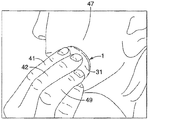
図1〜3を見ると、本発明の塗布器(1)の好適な長さ、幅、及び厚さが説明される。水平面(35)(例えば、水平なテーブルの上面)に沿って置かれたとき、塗布器(1)の長さは、その最も長い寸法である。水平面(35)に直行する、中心垂直軸(37)は、塗布器(1)の幾何学中心(図示せず)を通り抜ける。 1-3, the preferred length, width and thickness of the applicator (1) of the present invention will be described. When placed along a horizontal plane (35) (eg, the top surface of a horizontal table), the length of the applicator (1) is its longest dimension. A central vertical axis (37), orthogonal to the horizontal plane (35), passes through the geometric center (not shown) of the applicator (1).
塗布器(1)の幅は、同一の水平面(35)に沿ってその長さに垂直に測定される。本明細書の図によって説明される塗布器(1)について、塗布器(1)の最も厚い部分は、中心垂直軸(37)においてである。一実施形態では、塗布器の長さは、45mm〜70mm、好ましくは50mm〜65mm、あるいは55mm〜60mm、あるいはそれらの組み合わせである。塗布器の幅は、30mm〜60mm、好ましくは35mm〜55mm、あるいは40mm〜50mm、あるいはそれらの組み合わせである。塗布器の厚さは、0.5mm〜5mm、あるいは1mm〜4mmである。一実施形態では、中心垂直軸(37)で測定した厚さは、1mm〜4mm、あるいは2mm〜3.5mm、あるいは3mm〜4mm、あるいはそれらの組み合わせである。別の実施形態では、塗布の厚さ部分は、1mm〜4mm、あるいは2mm〜3.5mm、あるいは3mm〜4mm、あるいはそれらの組み合わせである。一実施形態では、塗布器の厚さは、6mmを超えず、好ましくは5mmを超えない、あるいは4mmを超えない。 The width of the applicator (1) is measured perpendicular to its length along the same horizontal plane (35). For the applicator (1) illustrated by the figures herein, the thickest part of the applicator (1) is at the central vertical axis (37). In one embodiment, the applicator length is 45 mm to 70 mm, preferably 50 mm to 65 mm, alternatively 55 mm to 60 mm, or a combination thereof. The width of the applicator is 30 mm to 60 mm, preferably 35 mm to 55 mm, or 40 mm to 50 mm, or a combination thereof. The thickness of the applicator is 0.5 mm to 5 mm, or 1 mm to 4 mm. In one embodiment, the thickness measured at the central vertical axis (37) is 1 mm to 4 mm, alternatively 2 mm to 3.5 mm, alternatively 3 mm to 4 mm, or a combination thereof. In another embodiment, the thickness portion of the application is 1 mm to 4 mm, alternatively 2 mm to 3.5 mm, alternatively 3 mm to 4 mm, or a combination thereof. In one embodiment, the applicator thickness does not exceed 6 mm, preferably does not exceed 5 mm, or does not exceed 4 mm.
図1は、塗布器の非限定的な実施例の透視図である。図2は、図1の塗布器の平面図であり、図2は、底面図である。これらの図で図示したように、塗布器(1)は、厚さの変化によって画定された少なくとも2つの領域(3、6)を有してもよい。外側領域(6)は、塗布器(1)の外周に最も近く、内側領域(3)を下回る厚さを有して画定される。内側領域(3)は、塗布器(1)の中心を含む。周縁(9)は、塗布器の最も外側の外周縁(9)として画定され、概ね楕円形状を形成する。好ましい実施形態では、図に例示するように、外側領域(6)は全体にわたり実質的に同じ厚さを有する。内側領域(3)は、外側領域(6)よりも厚い。図1及び2に最も良く例示するように、領域間境界(13)は、塗布器(1)の第1の表面(31)上に外側領域(6)と内側領域(3)との間の共通領域を画定する。領域間境界(13)は、周縁(9)によって定義された楕円形状(又は任意の他の形状)に似た楕円形状(又は曲線状の形状を含む任意の他の形状)を形成する。内側領域(3)は、第1の表面(31)から突出する楕円部分を有する。内側領域(3)は、領域間境界(13)から塗布器(1)の中心に向かって厚みを増す。一実施形態では、内側領域(3)の第1の表面(31)の表面積は、1cm2〜5cm2、好ましくは2cm2〜4cm2である。内側領域(3)の長さは、長軸(図示せず)に沿って、15〜25mm、好ましくは18〜22mm、あるいはそれらの組み合わせであってもよい。内側領域(3)の幅は、短軸(図示せず)に沿って、9mm〜19mm、あるいは11mm〜17mm、あるいは12mm〜15mm、あるいはそれらの組み合わせである。非限定的な一実施例では、内側領域(3)の長さ及び幅は、それぞれ20mm及び14mmである。 FIG. 1 is a perspective view of a non-limiting example of an applicator. FIG. 2 is a plan view of the applicator of FIG. 1, and FIG. 2 is a bottom view. As illustrated in these figures, the applicator (1) may have at least two regions (3, 6) defined by changes in thickness. The outer region (6) is defined with a thickness closest to the outer periphery of the applicator (1) and less than the inner region (3). The inner region (3) includes the center of the applicator (1). The periphery (9) is defined as the outermost outer periphery (9) of the applicator and forms a generally elliptical shape. In a preferred embodiment, as illustrated in the figure, the outer region (6) has substantially the same thickness throughout. The inner area (3) is thicker than the outer area (6). As best illustrated in FIGS. 1 and 2, the inter-region boundary (13) is between the outer region (6) and the inner region (3) on the first surface (31) of the applicator (1). A common area is defined. The inter-region boundary (13) forms an elliptical shape (or any other shape including a curvilinear shape) similar to the elliptical shape (or any other shape) defined by the periphery (9). The inner region (3) has an oval portion protruding from the first surface (31). The inner region (3) increases in thickness from the inter-region boundary (13) toward the center of the applicator (1). In one embodiment, the first surface area of the surface (31) of the inner region (3), 1 cm 2 to 5 cm 2, preferably 2cm 2 ~4cm 2. The length of the inner region (3) may be 15-25 mm, preferably 18-22 mm, or a combination thereof, along the long axis (not shown). The width of the inner region (3) is 9 mm to 19 mm, alternatively 11 mm to 17 mm, alternatively 12 mm to 15 mm, or a combination thereof along the minor axis (not shown). In one non-limiting example, the length and width of the inner region (3) are 20 mm and 14 mm, respectively.
代替の実施形態では、塗布器(1)は、周縁(9)によって画定された(曲線状の形状として)全体的な長円形状を有する。あるいは、領域間境界(13)は、長円形状を形成する。あるいは、内側領域(3)は、第1の表面(31)から突出する卵形の部分を有する。 In an alternative embodiment, the applicator (1) has an overall oval shape (as a curvilinear shape) defined by the periphery (9). Alternatively, the inter-region boundary (13) forms an oval shape. Alternatively, the inner region (3) has an oval part protruding from the first surface (31).
好ましくは、外側領域(6)は、外側領域全体にわたり0.5mm〜3mm、好ましくは1mm〜2.5mm、より好ましくは1mm〜2mmの均一の厚さを概ね有する。更にこれまでの一層好ましい実施形態では、内側領域(3)は、1.5mm〜5mm、好ましくは2.5mm〜4.5mm、より好ましくは3mm〜4mmの厚さを有する。 Preferably, the outer region (6) generally has a uniform thickness of 0.5 mm to 3 mm, preferably 1 mm to 2.5 mm, more preferably 1 mm to 2 mm over the entire outer region. Furthermore, in more preferred embodiments so far, the inner region (3) has a thickness of 1.5 mm to 5 mm, preferably 2.5 mm to 4.5 mm, more preferably 3 mm to 4 mm.
塗布器(1)の第1の表面(31)は、第2の表面(32)と対向する。第2の表面(32)は凹状であるが、第1の表面は概ね凸状である。主として顔の基質と接触するように構成されるのは第2の表面である。図3を参照すると、塗布器(1)の第2の表面(32)は、少なくとも2つの関連のある半径を有する(塗布器(1)が全体的な楕円形状を有するとき)。R5(24)、即ち第5の半径は、中心垂直軸(37)が第2の表面(32)と交差する場所と、周縁(2)が水平面(35)と交差する場所との間の軸線の最長距離である。R6(26)、即ち第6の半径は、中心垂直軸(37)が第2の表面(32)と交差する場所と、周縁(2)が水平面(35)と交差する場所との間の軸線の最短距離である。 The first surface (31) of the applicator (1) faces the second surface (32). The second surface (32) is concave, but the first surface is generally convex. It is the second surface that is configured to primarily contact the facial substrate. Referring to FIG. 3, the second surface (32) of the applicator (1) has at least two related radii (when the applicator (1) has an overall elliptical shape). R 5 (24), the fifth radius, is the distance between where the central vertical axis (37) intersects the second surface (32) and where the perimeter (2) intersects the horizontal plane (35). The longest distance of the axis. R 6 (26), the sixth radius, is the distance between where the central vertical axis (37) intersects the second surface (32) and where the perimeter (2) intersects the horizontal plane (35). The shortest distance of the axis.
R5(25)は、長軸面に沿って、R6(26)は短軸面に沿っている。したがって、R5(25)は、R6(26)よりも長い。一実施形態では、R5(25)は、19mm〜39mm、好ましくは24mm〜34mm、あるいは26mm〜32mm、あるいは25〜30mm、あるいは28mm〜33mm、あるいはそれらの組み合わせである。別の実施形態では、R6(26)は、12mm〜32mm、好ましくは17mm〜27mm、あるいは19mm〜25mm、あるいは20mm〜24mm、あるいはそれらの組み合わせである。更に別の実施形態では、塗布器の第2の表面(32)は、どんな突出部又はテクスチャ加工も無い又は実質的に無い。非限定的な実施例では、R5(25)及びR6(26)は、それぞれ28.25mm及び22mmである。 R 5 (25) is along the long axis surface and R 6 (26) is along the short axis surface. Therefore, R 5 (25) is longer than R 6 (26). In one embodiment, R 5 (25) is 19 mm to 39 mm, preferably 24 mm to 34 mm, alternatively 26 mm to 32 mm, alternatively 25 to 30 mm, alternatively 28 mm to 33 mm, or a combination thereof. In another embodiment, R 6 (26) is 12 mm to 32 mm, preferably 17 mm to 27 mm, alternatively 19 mm to 25 mm, alternatively 20 mm to 24 mm, or a combination thereof. In yet another embodiment, the second surface (32) of the applicator is free or substantially free of any protrusions or textures. In a non-limiting example, R 5 (25) and R 6 (26) are 28.25 mm and 22 mm, respectively.
図4は、短軸に沿った図1の塗布器の断面正面図である。図5は、図1の塗布器の長軸に沿った断面右図である。塗布器(1)の第2の表面(32)は、概ね凹状である。したがって、第1の表面(31)上に何らかの力を加えられることなく、塗布器(1)が水平面(35)に置かれるとき第2の表面(32)と水平面(35)との間に間隙が存在する。水平面(35)に接触するのは、周縁(9)に沿った第2の表面(32)である。最大間隙距離(図示せず)は、第2の表面(32)と水平面(35)との間の最大距離である。通常最大間隙距離は、中心垂直軸(37)に沿って測定される。最大間隙距離は、1mm〜5mm、好ましくは2mm〜4mmである。非限定的な一実施例では、最大間隙距離は、3mmであり、塗布器(1)の最も厚い部分は中心垂直軸(37)においてであり、3.3mmである。 4 is a cross-sectional front view of the applicator of FIG. 1 along the short axis. FIG. 5 is a right sectional view taken along the long axis of the applicator of FIG. The second surface (32) of the applicator (1) is generally concave. Thus, there is no gap between the second surface (32) and the horizontal surface (35) when the applicator (1) is placed on the horizontal surface (35) without any force being applied on the first surface (31). Exists. It is the second surface (32) along the periphery (9) that contacts the horizontal plane (35). The maximum gap distance (not shown) is the maximum distance between the second surface (32) and the horizontal plane (35). Usually the maximum gap distance is measured along the central vertical axis (37). The maximum gap distance is 1 mm to 5 mm, preferably 2 mm to 4 mm. In one non-limiting example, the maximum gap distance is 3 mm and the thickest part of the applicator (1) is at the central vertical axis (37) and is 3.3 mm.
図4は、R1、即ち第1の半径(21)、及びR2、即ち第2の半径(22)を示す。これらは、正確な縮尺率ではない。R1(21)及びR2(22)の外心は、それぞれ中心垂直軸(37)及び塗布器(1)の短軸面に沿って位置する。R1(21)は、短軸に沿った塗布器(1)の内側領域(3)の第1の表面(31)の弧の半径である。R2(22)は、短軸に沿った塗布器(1)の外側領域(6)の第1の表面(31)の弧の半径である。一実施形態では、R1(21)は、9mm〜19mm、好ましくは11mm〜17mm、より好ましくは12mm〜16mm、あるいはそれらの組み合わせである。別の実施形態では、R2(22)は、53mm〜93mm、好ましくは63mm〜83mm、あるいは67mm〜79mm、あるいは70mm〜76mm、あるいはそれらの組み合わせである。 FIG. 4 shows R 1 , the first radius (21), and R 2 , the second radius (22). These are not accurate scales. The outer centers of R 1 (21) and R 2 (22) are located along the central vertical axis (37) and the short axis surface of the applicator (1), respectively. R 1 (21) is the radius of the arc of the first surface (31) of the inner region (3) of the applicator (1) along the minor axis. R 2 (22) is the radius of the arc of the first surface (31) of the outer region (6) of the applicator (1) along the minor axis. In one embodiment, R 1 (21) is 9 mm to 19 mm, preferably 11 mm to 17 mm, more preferably 12 mm to 16 mm, or a combination thereof. In another embodiment, R 2 (22) is 53 mm to 93 mm, preferably 63 mm to 83 mm, alternatively 67 mm to 79 mm, alternatively 70 mm to 76 mm, or a combination thereof.
図5は、R3、即ち第3の半径(23)、及びR4、即ち第4の半径(24)を示す。R3(23)及びR4(24)の対応する外心は、それぞれ中心垂直軸(37)及び塗布器(1)の長軸面(図示せず)に沿って位置する。R3(23)は、長軸に沿った塗布器(1)の外側領域(6)の第1の表面の弧の半径である。R4(24)は、長軸に沿った塗布器(1)の内側領域(3)の第1の表面の弧の半径である。一実施形態では、R3(23)は、21mm〜33mm、好ましくは23mm〜31mm、あるいは25mm〜29mm、あるいはそれらの組み合わせである。別の実施形態では、R4(24)は、120mm〜200mm、好ましくは130mm〜190mm、好ましくは140mm〜180mm、あるいは150mm〜166mm、あるいは152mm〜164mm、あるいはそれらの組み合わせである。 FIG. 5 shows R 3 , the third radius (23), and R 4 , the fourth radius (24). The corresponding outer centers of R 3 (23) and R 4 (24) are located along the central vertical axis (37) and the major axis surface (not shown) of the applicator (1), respectively. R 3 (23) is the radius of the arc of the first surface of the outer region (6) of the applicator (1) along the long axis. R 4 (24) is the radius of the arc of the first surface of the inner region (3) of the applicator (1) along the long axis. In one embodiment, R 3 (23) is 21 mm to 33 mm, preferably 23 mm to 31 mm, alternatively 25 mm to 29 mm, or a combination thereof. In another embodiment, R 4 (24) is 120 mm to 200 mm, preferably 130 mm to 190 mm, preferably 140 mm to 180 mm, alternatively 150 mm to 166 mm, alternatively 152 mm to 164 mm, or a combination thereof.
図6は、周縁(9)に最も近い塗布器(1)の分解組立て及び断面図である。図6は、R7、即ち第7の半径(27)を示す。R7(27)は、周縁(9)の外側表面から測定された周縁(9)の弧の半径である。好ましくは、R7は、塗布器(1)の周囲方向に一周して同じである。一実施形態では、R7(27)は、0.01mm〜2mmである。 FIG. 6 is an exploded assembly and cross-sectional view of the applicator (1) closest to the periphery (9). FIG. 6 shows R 7 , the seventh radius (27). R 7 (27) is the radius of the arc of the rim (9) measured from the outer surface of the rim (9). Preferably, R 7 is the same around the circumference of the applicator (1). In one embodiment, R 7 (27) is 0.01 mm to 2 mm.
塗布器の質量は、1.0g〜500gである。 The mass of the applicator is 1.0 g to 500 g.
理論に束縛されるものではないが、外側領域(6)よりも厚い内側領域(3)を有する潜在的効果が存在する。より大きな厚さは、改善された成形加工を提供し得る。更に、塗布器(1)の第1の表面(31)からの内側領域(3)の楕円形状の突出部(又は任意の他の形状の突出部)は、初心者ユーザーが適切な指の向きのもとで使用するのを、及び恐らく初心者ユーザーの指が使用中に滑ることを回避するのを支援し得る。突出部は、中心における塗布器の剛性を補助して、周縁(9)への下方向の力を均等に分配するのに役立ち得る。突出部の寸法は、スキンケア組成物のうちどのくらいを投与するべきかをユーザーに対して視覚化するのに役立ち得る。最後に、バルク包装中に何らかの相互付着(co-adhesion)が発生したときに、塗布器をより分離しやすくすることにより、加工は突出部で改善され得る。 Without being bound by theory, there is a potential effect with the inner region (3) being thicker than the outer region (6). Larger thicknesses can provide improved molding processes. In addition, the oval shaped protrusion (or any other shaped protrusion) of the inner region (3) from the first surface (31) of the applicator (1) allows the novice user to have an appropriate finger orientation. It may help to avoid using the original and possibly slipping novice user's finger during use. The protrusions can help distribute the downward force evenly on the periphery (9), assisting the applicator stiffness in the center. The dimensions of the protrusions can help visualize to the user how much of the skin care composition should be administered. Finally, processing can be improved with protrusions by making the applicator easier to separate when some co-adhesion occurs during bulk packaging.
屈曲力
発明の別の態様は、屈曲力において適切なバランスを有するための塗布器を提供する。ヒトの顔の複雑な輪郭に適合するために、毛の横たわり効果をもたらすのに十分だが、柔軟性不足になるほど多すぎない屈曲力がある必要がある。表1a及び1bは、10個の塗布器の寸法(及び標準偏差)をまとめてある。表2a及び2bは、表1及び1bに記載された塗布器からの屈曲力試験の結果をまとめてある。
Bending force Another aspect of the invention provides an applicator for having an appropriate balance in bending force. In order to conform to the complex contours of the human face, there needs to be enough flexing force to provide a hair lying effect but not so much flexibility as to be inflexible. Tables 1a and 1b summarize the dimensions (and standard deviation) of the 10 applicators. Tables 2a and 2b summarize the results of the bending force test from the applicator described in Tables 1 and 1b.

2外側領域(6)全体にわたり外側領域(6)の厚さが実質的に均一である外側領域(6)の厚さ。
3「高さ」は、水平面(35)から塗布器(1)の第1の表面(31)まで中心垂直軸(35)に沿って測定された距離である。換言すれば、中心垂直軸(37)に沿って最大間隙距離に内側領域(3)の厚さを加えたものである。所与の材料の特性、塗布器の質量、及び下に向けた塗布器の凹状面、並びに塗布の全体的形状は、本明細書の「高さ」寸法に影響を与え得る変数であることが理解されるべきである。
4半径R1、R2、R3、R4、R5、及びR6は、上で予め定義されている。
2 Thickness of the outer region (6) where the thickness of the outer region (6) is substantially uniform throughout the outer region (6).
3 “Height” is the distance measured along the central vertical axis (35) from the horizontal plane (35) to the first surface (31) of the applicator (1). In other words, the thickness of the inner region (3) is added to the maximum gap distance along the central vertical axis (37). The properties of a given material, applicator mass, and the concave surface of the applicator facing down, as well as the overall shape of the application, can be variables that can affect the “height” dimensions herein. Should be understood.
The four radii R 1 , R 2 , R 3 , R 4 , R 5 , and R 6 are predefined above.
上の表1a及び1bに指定された寸法を有する10個の塗布器それぞれを、屈曲力について塗布器の様々な場所で評価する。力平均値(ニュートン)及び標準偏差を下の表2a及び表2bにまとめる。INSTRONブランドモデルは、屈曲力を評価するのに好適な計器である。計器は、円形かつ扁平(直径1cm)の接触領域を有するステンレス鋼プローブを有し、計器のロードセルに装着される。プローブは、下方向(即ち、水平のベンチトップに対して直交方向に下)に押し下げる。屈曲力は、周縁(9)、楕円形状の塗布器(1)のそれぞれの長軸及び短軸、及びそれぞれの第1の表面(31)及び第2の表面(32)にて評価される。プローブの接触領域を、(それぞれの表面(31、32)にて)プローブの中心が周縁(9)の最も外側の縁部に接触するように周縁(9)に向ける。塗布器(1)は、力測定用のCクランプに固定され、Cクランプは塗布器の幾何学中心にて第1の表面(31)及び第2の表面(32)に接して塗布器を固定する。Cクランプは、それぞれの表面(31、32)で各クランプにつき0.25cm2の接触表面積を有する。各クランプの接触領域は、円形かつ扁平である。 Each of the ten applicators having the dimensions specified in Tables 1a and 1b above is evaluated for flexural forces at various locations on the applicator. The force mean (Newton) and standard deviation are summarized in Tables 2a and 2b below. The INSTRON brand model is a suitable instrument for evaluating flexural force. The instrument has a stainless steel probe with a circular and flat (1 cm diameter) contact area and is attached to the instrument's load cell. The probe is pushed down (ie down perpendicular to the horizontal bench top). The bending force is evaluated at the peripheral edge (9), the major and minor axes of the elliptical applicator (1), and the first and second surfaces (31) and (32), respectively. The probe contact area is oriented (at the respective surface (31, 32)) towards the periphery (9) so that the center of the probe contacts the outermost edge of the periphery (9). The applicator (1) is fixed to a C-clamp for force measurement, and the C-clamp contacts the first surface (31) and the second surface (32) at the geometric center of the applicator to fix the applicator. To do. The C-clamp has a contact surface area of 0.25 cm 2 for each clamp at each surface (31, 32). The contact area of each clamp is circular and flat.
力測定を塗布器(1)の長軸及び短軸にて行った。1セットの測定では、プローブの接触領域を長軸及び短軸にて第1の表面(31)に向けたままで、第2の表面(32)は下向き、即ち、凹状面が下向きである。別のセットの測定では、プローブの接触領域を長軸及び短軸にて塗布器(1)の第2の表面(32)に向けたままで、第2の表面(32)は上向き、即ち、凹状面が上向きであるそれぞれの軸にて、それぞれの表面(31、32)の屈曲力の差異率を比較する。表2aは短軸に関し、表2bは長軸に関する。 Force measurement was performed on the major and minor axes of the applicator (1). In one set of measurements, the second surface (32) is facing down, i.e. the concave surface is facing down, with the probe contact area facing the first surface (31) at the major and minor axes. In another set of measurements, the contact area of the probe is oriented with the major and minor axes towards the second surface (32) of the applicator (1), with the second surface (32) facing up, ie concave. The difference rate of the bending force of each surface (31, 32) is compared at each axis with the surface facing upward. Table 2a relates to the short axis and Table 2b relates to the long axis.
2プローブが塗布器の第2の表面(32)に接触している(即ち、凹状面がプローブに接触している)。
2 The probe is in contact with the second surface (32) of the applicator (ie the concave surface is in contact with the probe).
短軸については、内向きに、塗布器の後縁を通って、皮膚に分散された材料に手を加えるのに使用される塗布器の外側縁部における皮膚に対する下向き抵抗力の好ましい範囲は、0.01804ニュートン力〜0.20224ニュートン力に幅広く分布するべきである。面、又は短軸の抵抗力のより好ましい範囲は、0.04874〜0.17154ニュートン力の範囲であるべきである。最も好ましい外側下向抵抗力は、0.07944〜0.14084ニュートン力であるべきである。 For the short axis, the preferred range of downward resistance to the skin at the outer edge of the applicator used to modify the material dispersed in the skin, inward, through the rear edge of the applicator is It should be widely distributed from 0.01804 Newton force to 0.20224 Newton force. A more preferred range of surface or minor axis resistance should be in the range of 0.04874 to 0.17154 Newton forces. The most preferred outward downward drag force should be 0.07944-0.14084 Newton force.
4プローブが塗布器の第2の表面(32)に接触している(即ち、凹状面がプローブに接触している)。
4 The probe is in contact with the second surface (32) of the applicator (ie the concave surface is in contact with the probe).
先の短軸の範囲と対照的に、塗布器の後縁を通って、材料の十分な膜に手を加えるのに必要な皮膚での長軸の下向き抵抗力は、0.03157〜0.15463ニュートン力であるのが好ましい。抵抗圧のより好ましい範囲は、0.05208〜0.13412ニュートン力である。抵抗力の最も好ましい範囲は、0.06153〜0.11361ニュートン力である。 In contrast to the previous short axis range, the downward resistance force of the long axis on the skin required to manipulate sufficient film of material through the trailing edge of the applicator is 0.03157-0. A 15463 Newton force is preferred. A more preferable range of the resistance pressure is 0.05208 to 0.13412 Newton force. The most preferred range of resistance is 0.06153-0.1361 Newton force.
表2a及び2bに示すように、第2の表面(32)に対する屈曲力は、第1の表面(31)に対する屈曲力よりも大きい。理論に束縛されるものではないが、塗布器のZ軸における複合曲率(即ち、「カップ形状」)は、塗布器内で内力の分布を形成する。形状は、本明細書で説明したエラストマー材の使用と相まって、顔の基質へのスキンケア組成物の平坦かつ平滑な付着を可能にする。この内力の分布は、組成物塗布のために顔の基質に対し塗布器の接触点での適量の下向き圧力を可能にするが、また接触縁に先立って使用中に接触縁(ひいては顔の基質)への組成物の均一な流れを提供する組成物のリザーバを維持する適量の圧力も提供する。更に、表面(31、32)間の屈曲力のこの偏りはまた、塗布中のユーザーの指の圧力をより少なくして、したがって顔の基質に対する下向き圧力のより均一な分布を可能にする。これにより、所望の平坦かつ平滑な組成物の付着を達成しながら、より広い範囲のユーザーの指の反対方向の圧力の変化が可能になる。 As shown in Tables 2a and 2b, the bending force on the second surface (32) is greater than the bending force on the first surface (31). Without being bound by theory, the compound curvature (ie, “cup shape”) in the Z axis of the applicator forms a distribution of internal forces within the applicator. The shape, coupled with the use of the elastomeric material described herein, allows for a flat and smooth attachment of the skin care composition to the facial substrate. This internal force distribution allows an appropriate amount of downward pressure at the applicator contact point against the facial substrate for composition application, but also during use prior to the contact edge (and thus the facial substrate). An appropriate amount of pressure is also provided to maintain a reservoir of the composition that provides a uniform flow of the composition to the Furthermore, this bias of bending force between the surfaces (31, 32) also reduces the pressure of the user's finger during application, thus allowing a more even distribution of the downward pressure on the facial substrate. This allows a wider range of pressure changes in the opposite direction of the user's finger while achieving the desired flat and smooth composition deposition.
発明の一態様は、第1の表面(31)が周縁(9)で測定された第1の屈曲力を有し、第2の表面(32)が周縁(9)で測定された第2の屈曲力を有し、第2の屈曲力が第1の屈曲力より少なくとも1.1倍、好ましくは1.1〜10、より好ましくは1.5〜5、あるいは2〜5、あるいはそれらの組み合わせ、の倍数大きい、塗布器(1)を提供する。 One aspect of the invention is that the first surface (31) has a first bending force measured at the periphery (9) and the second surface (32) is measured at the periphery (9). Having a bending force, the second bending force being at least 1.1 times the first bending force, preferably 1.1-10, more preferably 1.5-5, alternatively 2-5, or combinations thereof An applicator (1) is provided that is a multiple of.
表面摩擦
発明の一態様は、平滑な表面、好ましくは目標の皮膚基質と接触するように構成される表面を有する塗布器を提供する。そのような平滑な表面は、スキンケア組成物、特に毛髪横たわり効果を提供するスキンケア組成物のより効果的な塗布を提供する。塗布器の平滑な表面を測定する1つの方法は、表面摩擦によるものである。摩擦を解析する1つの好適な方法は、Kato Tech Co.,Ltd.(Kyoto,Japan)により製造された「KES−SE」摩擦テスタの使用によるものである。本発明の非限定的な塗布器は、0.65の摩擦係数つまり「COF」を測定する(対照の「粗面板」の測定値は0.43である(通常の測定値は0.36〜0.45である)。一実施形態では、未使用の塗布器のCOFは、0.5〜0.9、あるいは0.55〜0.75である。
Surface Friction One aspect of the invention provides an applicator having a smooth surface, preferably a surface configured to contact a target skin matrix. Such a smooth surface provides a more effective application of skin care compositions, particularly skin care compositions that provide a hair laying effect. One method of measuring the smooth surface of the applicator is by surface friction. One suitable method for analyzing friction is Kato Tech Co. , Ltd., Ltd. (Kyoto, Japan) by using a “KES-SE” friction tester. The non-limiting applicator of the present invention measures a coefficient of friction or “COF” of 0.65 (the measured value of the control “rough plate” is 0.43 (the usual measured value is 0.36 to In one embodiment, the COF of the unused applicator is 0.5-0.9, alternatively 0.55-0.75.
表面エネルギー
表面エネルギーは、平滑な表面を特徴付ける別の方法である。「Owens−Wendt表面エネルギー」を測定する1つの好適な方法は、First Ten Angstroms,Inc.(Portsmouth,Virginia,U.S.A.)により製造されるFTA1000 Drop Shape Instrumentationを使用することである。(i)分散型相互作用による表面エネルギー(そのため「分散型成分」と呼ばれる)、(ii)極性相互作用による表面エネルギー(そのため「極性成分」と呼ばれる)を加算して、Owens−Wendt表面エネルギーを求める。ガラス顕微鏡スライド及びプラスチックの顕微鏡カバースリップが対照として使用される。結果は以下の表中にまとめられる。
Surface energy Surface energy is another way to characterize a smooth surface. One suitable method for measuring “Owens-Wendt surface energy” is First Ten Angstroms, Inc. (Portsmouth, Virginia, U.S.A.) manufactured by FTA1000 Drop Shape Instrumentation. (I) Surface energy due to dispersion interaction (hence called “dispersion component”) and (ii) Surface energy due to polarity interaction (hence called “polar component”) are added to obtain Owens-Wendt surface energy. Ask. Glass microscope slides and plastic microscope cover slips are used as controls. The results are summarized in the following table.
一実施形態では、塗布器(1)の外部表面(好ましくは第2の表面(32))は、17ダイン/cm〜37ダイン/cm、好ましくは32ダイン/cm〜42ダイン/cm、あるいはそれらの組み合わせの表面エネルギーを含む。 In one embodiment, the outer surface of the applicator (1) (preferably the second surface (32)) is 17 dynes / cm to 37 dynes / cm, preferably 32 dynes / cm to 42 dynes / cm, or they Including the surface energy of the combination.
硬度
塗布器の非限定的な実施例の硬度値は、デュロメータスケールAで39.8と評価される。一実施形態では、塗布器は、30〜60、好ましくは35〜50のデュロメータスケールAで測定された硬度値を含む。材料の柔軟性/しなやかさは、後縁でより多くの力を割り当てるはずである。塗布器のデュロメータは、ショアスケールA(Asker Durometer model XP−A)デュロメータテスタで測定された。
Hardness The hardness value of a non-limiting example of an applicator is rated 39.8 on the durometer scale A. In one embodiment, the applicator includes a hardness value measured on a durometer scale A of 30-60, preferably 35-50. The flexibility / flexibility of the material should assign more force at the trailing edge. The durometer of the applicator was measured with a Shore Scale A (Asker Durometer model XP-A) durometer tester.
スキンケア組成物
塗布器による皮膚への局所的塗布に好適なスキンケア組成物は、本質的に任意の皮膚科学的に安全な組成物であってもよい。好ましい実施形態では、組成物は、塗布器と組み合わせて機能するための、毛を柔らかくする1つ以上の成分(例えば、グリセロール)を含有し、毛、好ましくは顔の毛、好ましくはヒト女性の微細な顔の毛の外観を最小化する。別の好ましい実施形態では、組成物は、ファンデーションのような微細な顔の毛をカバーするための1つ以上の成分を含有する。より好ましくは、スキンケア組成物は、毛髪軟化成分及び毛又は皮膚の被覆剤(例えば、顔料)の両方を含む。顔料を使用してもよいが、代替の好ましい組成物は本質的に顔料を含まない。他の実施形態では、顔料濃度は標準であってもよいか、又は低減した濃度の顔料を使用してもよい。他の成分はまた、日焼け止め剤又は皮膚美白剤のような組成物に含まれてもよい。好ましくは、スキンケア組成物は、皮膚の毛孔をふさぐことなく、敏感肌に好適であり、皮膚科学的に試験されている。好ましい実施形態では、スキンケア組成物は、ある程度毛髪横たわり効果を提供する膜形成組成物である。膜形成組成物(例えばMQ樹脂)は当該技術分野において既知である。例えば、国際公開第97/17057号、同第98/52515号を参照されたい。
Skin Care Composition A skin care composition suitable for topical application to the skin with an applicator may be essentially any dermatologically safe composition. In a preferred embodiment, the composition contains one or more ingredients that soften the hair (eg, glycerol) to function in combination with the applicator, and the hair, preferably facial hair, preferably human female. Minimize the appearance of fine facial hair. In another preferred embodiment, the composition contains one or more ingredients for covering fine facial hair such as a foundation. More preferably, the skin care composition comprises both a hair softening component and a hair or skin coating (eg, pigment). Although pigments may be used, an alternative preferred composition is essentially free of pigments. In other embodiments, the pigment concentration may be standard or a reduced concentration of pigment may be used. Other ingredients may also be included in compositions such as sunscreens or skin lightening agents. Preferably, the skin care composition is suitable for sensitive skin without occluding the skin pores and has been dermatologically tested. In a preferred embodiment, the skin care composition is a film-forming composition that provides some hair laying effect. Film forming compositions (eg MQ resins) are known in the art. See, for example, WO 97/17057 and 98/52515.
別の実施形態では、スキンケア組成物は一般により高い粘度を有する。理論に束縛されるものではないが、より高い粘性の組成物は、より低い粘性の組成物に比べて流れないため顔により良好な被覆又は塗布を提供することができ、したがって、塗布器を介しユーザーに塗布される組成物に対してより多くの時間、並びに顔の皮膚及び微細な顔の毛によって吸収される組成物に対してより多くの時間を与える。本発明の塗布器は、そのようなより高い粘度の組成物を塗布するのに特に好適である。本申請で述べた全ての粘度は、特に指定がないかぎりブルックフィールド粘度である。スキンケア組成物の好適なブルックフィールド粘度の範囲は、100センチポアズ(cps)〜200,000cps、好ましくは15,000cps〜90,000cps、より好ましくは15,000cps〜60,000cpsの範囲を含んでもよく、あるいは39.8ショアA硬度を有する塗布器については、好ましい範囲は、15,000cps〜40,000cps、及びあるいはそれらの組み合わせである。粘度を測定する1つの好適な方法は、Heliopathモードで、1分につき5回転(RPM)のスピンドル速度(及び周囲条件下)でブルックフィールドRVT、スピンドルCを使用することが挙げられる。理論に束縛されるものではないが、凹状面を有する塗布器(1)の第2の表面(32)は、ユーザーが第2の表面上に組成物を分注する間にスキンケア組成物を保持するのに役立つ。塗布器の凹状の第2の表面は、塗布器の使用中にリザーバとしての機能を果たすので、スキンケア組成物は塗布器の中心からより多く塗布される。これは、塗布器の両側にスキンケア組成物を移動させる直線状のスキージとしての機能を果たす一部の他の塗布器とは際立って対照的である。これは塗布のためのユーザーによる塗布器のストロークをより多くすること(塗布の時間の増加)、及び微細な顔の毛の生えている向きと一致しない方向に不必要にスキンケア組成物を無理に移動させることにつながることがあり、その結果潜在的に次善の毛髪横たわり結果につながる。 In another embodiment, the skin care composition generally has a higher viscosity. Without being bound by theory, a higher viscosity composition can provide a better coating or application to the face because it does not flow as compared to a lower viscosity composition, and therefore via an applicator. It gives more time for the composition applied to the user and more time for the composition absorbed by the facial skin and fine facial hair. The applicator of the present invention is particularly suitable for applying such higher viscosity compositions. All viscosities mentioned in this application are Brookfield viscosities unless otherwise specified. Suitable Brookfield viscosity ranges for skin care compositions may include a range of 100 centipoise (cps) to 200,000 cps, preferably 15,000 cps to 90,000 cps, more preferably 15,000 cps to 60,000 cps, Alternatively, for an applicator having a 39.8 Shore A hardness, the preferred range is 15,000 cps to 40,000 cps, and / or combinations thereof. One suitable method for measuring viscosity includes using a Brookfield RVT, spindle C in Heliopath mode at a spindle speed of 5 revolutions per minute (RPM) (and ambient conditions). Without being bound by theory, the second surface (32) of the applicator (1) having a concave surface holds the skin care composition while the user dispenses the composition onto the second surface. To help. The concave second surface of the applicator serves as a reservoir during use of the applicator so that more skin care composition is applied from the center of the applicator. This is in sharp contrast to some other applicators that serve as a linear squeegee that moves the skin care composition to both sides of the applicator. This increases the stroke of the applicator by the user for application (increased application time) and unnecessarily forces the skin care composition in a direction that does not match the orientation of the fine facial hair Can lead to movement, potentially resulting in sub-optimal hair laying results.
スキンケア組成物の粘度は、本発明の塗布器を用いた皮膚上の製品の有効適用範囲に有意な影響を及ぼし得る。高ショアAの塗布器とともに使用される低粘度組成物は、流体が塗布器の後縁の下向きの力に打ち勝つ十分な流体力学抵抗を発揮できないため、塗布器からうまく分注することができない。あるいは、高粘度組成物は、低ショアAの塗布器と併用するとき、高レベルの流体力学抵抗及び比較的低い後縁の力のためにむらのある付着をもたらすことがある。 The viscosity of the skin care composition can significantly affect the effective coverage of the product on the skin using the applicator of the present invention. Low viscosity compositions used with high Shore A applicators cannot dispense well from the applicator because the fluid cannot provide sufficient hydrodynamic resistance to overcome the downward force on the trailing edge of the applicator. Alternatively, high viscosity compositions may result in uneven adhesion due to high levels of hydrodynamic resistance and relatively low trailing edge forces when used with low Shore A applicators.
一実施形態では、本発明の塗布器と併用されるスキンケア組成物は、塗布器の硬度に相関する粘度を有する。約39〜45のショアA硬度を有する塗布器については、スキンケア組成物は、約15,000cps〜40,000cpsの粘度を有するだろう。あるいは、約55〜60のショアA硬度を有する塗布器については、スキンケア組成物は、約68,000cps〜90,000cpsの粘度を有するだろう。あるいは、約47のショアA硬度を有する塗布器については、スキンケア組成物は、約100cps〜90,000cps、より好ましくは約15,000cps〜90,000cpsの粘度を有するだろう。 In one embodiment, the skin care composition used with the applicator of the present invention has a viscosity that correlates to the hardness of the applicator. For applicators having a Shore A hardness of about 39-45, the skin care composition will have a viscosity of about 15,000 cps to 40,000 cps. Alternatively, for an applicator having a Shore A hardness of about 55-60, the skin care composition will have a viscosity of about 68,000 cps to 90,000 cps. Alternatively, for an applicator having a Shore A hardness of about 47, the skin care composition will have a viscosity of about 100 cps to 90,000 cps, more preferably about 15,000 cps to 90,000 cps.
スキンケア製剤のずり減粘作用はまた、塗布の剪断速度が>100s-1であることから均一な付着に重要である。使用時に塗布器は動いて流体上にずり応力を発揮する。結果として、速度勾配が働き、小さいギャップ厚のため高い剪断速度が生じる。「塗布」又は「摩擦」の代表的な剪断速度は、>100s-1であり、結果として、ずり減粘製品は塗布に対し、より少ない抵抗を働かせるだろう。粘度は、流体の構造を定量化するための共通の工業的方法であるブルックフィールド粘度として定義された。加えて、ずり応力の増加及び結果として生じる粘度の測定のために流体を働かせることによって、TA instrumentのAR−G2レオメーターを用いて定常状態の流動曲線を作成した。当該分野で既知のものに共通であるように、データを次に構成的なCarreauモデルに適合させて、そのデータを共通の剪断速度に適合させた(この事例では10及び100s-1)。 The shear-thinning effect of skin care formulations is also important for uniform adhesion since the shear rate of application is> 100 s −1 . During use, the applicator moves and exerts a shear stress on the fluid. As a result, a velocity gradient works and a high shear rate occurs due to the small gap thickness. Typical shear rates for “application” or “friction” are> 100 s −1 , and as a result, shear-thinning products will exert less resistance to application. Viscosity was defined as Brookfield viscosity, a common industrial method for quantifying fluid structure. In addition, a steady state flow curve was generated using a TA instrument AR-G2 rheometer by working the fluid for increased shear stress and resulting viscosity measurements. As is common to what is known in the art, the data was then fitted to a constitutive Carreau model to fit the data to a common shear rate (10 and 100 s −1 in this case).
加えて、デュロメータが測定した同じ形状を有する塗布器材料の硬度を、組成物により変化させて、個々の製品流体の粘度により理想的な硬度の塗布器を作製することができる。具体的には、本明細書で説明した長円形形状については、塗布器のデュロメータ硬度は、ショアA20〜ショアA80、より好ましくはショアA30〜ショアA65、及び具体的にはショアA39〜ショアA59の範囲であってもよい。複数の塗布器の硬度を付けた材料の全てを同じ形状と比較することによって、製品粘度の特定の範囲に対する塗布器の硬度の理想的な範囲を決定することが可能である。特に、39.8のショアA硬度は、100cps〜19,900cpsの範囲の粘度に対し最良の製品付着性能を有する。同様に、47のショアA硬度を有する塗布器は、20Kcps〜69.9Kcpsの製品粘度で最も望ましい付着パターンを作製した。更に、59のショアA硬度を有する塗布器は、70K〜200Kcpsの粘度でより好ましい付着パターンを供給する。 In addition, the hardness of the applicator material having the same shape as measured by the durometer can be varied by the composition to make an applicator of ideal hardness due to the viscosity of the individual product fluids. Specifically, for the oval shape described herein, the durometer hardness of the applicator is from Shore A20 to Shore A80, more preferably from Shore A30 to Shore A65, and specifically from Shore A39 to Shore A59. It may be a range. By comparing all of the applicator-hardened materials to the same shape, it is possible to determine the ideal range of applicator hardness for a specific range of product viscosities. In particular, a Shore A hardness of 39.8 has the best product adhesion performance for viscosities ranging from 100 cps to 19,900 cps. Similarly, an applicator having a Shore A hardness of 47 produced the most desirable adhesion pattern with product viscosities of 20 Kcps to 69.9 Kcps. In addition, an applicator having a Shore A hardness of 59 provides a more favorable deposition pattern with a viscosity of 70 K to 200 Kcps.
化粧品組成物は、従来の方法によって以下の成分から調製された。 A cosmetic composition was prepared from the following ingredients by conventional methods.
*2)PVP(100%)(BASF Corporation)
*3)アクリレート/エチルヘキシルアクリレートコポリマー(100%)(Daito Kasei Kogyo Co.,Ltd.)
*4)二酸化チタン及び水酸化アルミニウム及びタルク及びマグネシウムステアレート及びジメチコン(Miyoshi Kasei,Inc.)
*5)二酸化チタン及び水酸化アルミニウム及びタルク及びマグネシウムステアレート(Miyoshi Kasei,Inc.)
*6)PEG−9ポリジメチルシロキシエチルジメチコン(Shin−Etsu Chemical Co.)
*7)イソステアレス−2(Croda,Inc.)
*8)ステアレス−21(Croda,Inc.)
*9)デキストリンパルミテート(Chiba Flour Milling Company,Ltd.)
*10)二酸化チタン及びシクロメチコン及びジメチコン及びステアロイルグルタミン酸二ナトリウム及び水酸化アルミニウム(Miyoshi Kasei,Inc.)
*11)酸化鉄及びシクロメチコン及びジメチコン及びステアロイルグルタミン酸二ナトリウム及び水酸化アルミニウム(Miyoshi Kasei,Inc.)
*12)酸化鉄及びシクロメチコン及びジメチコン及びステアロイルグルタミン酸二ナトリウム及び水酸化アルミニウム(Miyoshi Kasei,Inc.)
*13)酸化鉄及びシクロメチコン及びジメチコン及びステアロイルグルタミン酸二ナトリウム及び水酸化アルミニウム(Miyoshi Kasei,Inc.)
*14)酸化鉄及びメチコン(Daito Kasei Kogyo Co.,Ltd.)
*15)酸化鉄及びメチコン(Daito Kasei Kogyo Co.,Ltd.)
*16)酸化鉄及びメチコン(Daito Kasei Kogyo Co.,Ltd.)
*17)二酸化チタン及び水酸化アルミニウム及びジメチコン(Miyoshi Kasei,Inc.)
*18)タルク及びメチコン(Miyoshi Kasei,Inc.)
*19)シリカ及びメチコン(Miyoshi Kasei,Inc.)
*20)タルク及びメチコン(Miyoshi Kasei,Inc.)
*21)シリカ(Presperse LLC)
*22)二酸化チタン及び水酸化アルミニウム及びメトキシPEG−10プロピルトリメトキシシラン及びシリカ(Daito Kasei Kogyo Co.,Ltd.)
*23)酸化鉄及びメトキシPEG−10プロピルトリメトキシシラン及びシリカ(Daito Kasei Kogyo Co.,Ltd.)
*24)酸化鉄及びメトキシPEG−10プロピルトリメトキシシラン及びシリカ(Daito Kasei Kogyo Co.,Ltd.)
*25)酸化鉄及びメトキシPEG−10プロピルトリメトキシシラン及びシリカ(Daito Kasei Kogyo Co.,Ltd.)
*26)ポリアクリルアミド及び水及びC13〜14イソパラフィン及びLaureth−7(Seppic)
*27)ポリアクリル酸ナトリウムデンプン(Daito Kasei Kogyo Co.,Ltd.)
*28)DC−5225C(Dow Corning)
* 2) PVP (100%) (BASF Corporation)
* 3) Acrylate / ethylhexyl acrylate copolymer (100%) (Daito Kasei Kogyo Co., Ltd.)
* 4) Titanium dioxide and aluminum hydroxide and talc and magnesium stearate and dimethicone (Miyoshi Kasei, Inc.)
* 5) Titanium dioxide and aluminum hydroxide and talc and magnesium stearate (Miyoshi Kasei, Inc.)
* 6) PEG-9 polydimethylsiloxyethyl dimethicone (Shin-Etsu Chemical Co.)
* 7) Isosteales-2 (Croda, Inc.)
* 8) Steareth-21 (Croda, Inc.)
* 9) Dextrin palmitate (Chiba Floor Milling Company, Ltd.)
* 10) Titanium dioxide and cyclomethicone and dimethicone and disodium stearoyl glutamate and aluminum hydroxide (Miyoshi Kasei, Inc.)
* 11) Iron oxide, cyclomethicone and dimethicone, disodium stearoyl glutamate and aluminum hydroxide (Miyoshi Kasei, Inc.)
* 12) Iron oxide and cyclomethicone and dimethicone and stearoyl glutamate disodium and aluminum hydroxide (Miyoshi Kasei, Inc.)
* 13) Iron oxide, cyclomethicone, dimethicone, and disodium stearoyl glutamate and aluminum hydroxide (Miyoshi Kasei, Inc.)
* 14) Iron oxide and methicone (Daito Kasei Kogyo Co., Ltd.)
* 15) Iron oxide and methicone (Daito Kasei Kogyo Co., Ltd.)
* 16) Iron oxide and methicone (Daito Kasei Kogyo Co., Ltd.)
* 17) Titanium dioxide and aluminum hydroxide and dimethicone (Miyoshi Kasei, Inc.)
* 18) Talc and methicone (Miyoshi Kasei, Inc.)
* 19) Silica and methicone (Miyoshi Kasei, Inc.)
* 20) Talc and methicone (Miyoshi Kasei, Inc.)
* 21) Silica (Presperse LLC)
* 22) Titanium dioxide and aluminum hydroxide and methoxy PEG-10 propyltrimethoxysilane and silica (Daito Kasei Kogyo Co., Ltd.)
* 23) Iron oxide and methoxy PEG-10 propyltrimethoxysilane and silica (Daito Kasei Kogyo Co., Ltd.)
* 24) Iron oxide and methoxy PEG-10 propyltrimethoxysilane and silica (Daito Kasei Kogyo Co., Ltd.)
* 25) Iron oxide and methoxy PEG-10 propyltrimethoxysilane and silica (Daito Kasei Kogyo Co., Ltd.)
* 26) Polyacrylamide and water and C13-14 isoparaffin and Laureth-7 (Seppic)
* 27) Sodium polyacrylate starch (Daito Kasei Kogyo Co., Ltd.)
* 28) DC-5225C (Dow Corning)
実施例1〜3及び比較例1に関しては、適当な容器内にて、増粘剤(SEPIGEL 305 *26)以外の全ての親水性及び水溶性成分をともにブレンドし、全ての成分が溶解するまで混合した。別の容器内で、増粘剤(RHEOPEARL KL2 *9)以外の全ての疎水性及び油溶性の成分をブレンドし、全ての成分が均質になるまで混合した。上記の親水性成分及び疎水性成分を乳化のために混合する。得られたエマルションに増粘剤を加え、そのエマルションを穏やかに混合した。RHEOPEARL KL2が増粘剤である場合は、エマルションを90Cになるまで加熱してから冷却した。 For Examples 1-3 and Comparative Example 1, in a suitable container, all hydrophilic and water-soluble components other than the thickener (SEPIGEL 305 * 26) are blended together until all components are dissolved. Mixed. In a separate container, all hydrophobic and oil-soluble ingredients except the thickener (RHEOPEARL KL2 * 9) were blended and mixed until all ingredients were homogeneous. The above hydrophilic component and hydrophobic component are mixed for emulsification. A thickener was added to the resulting emulsion and the emulsion was gently mixed. When RHEOPEARL KL2 was a thickener, the emulsion was heated to 90C and then cooled.
実施例4に関しては、適当な容器内にて、増粘剤(SEPIGEL 305 *26及びMAKIMOUSSE 12 *27)以外の全ての親水性及び水溶性成分をともにブレンドし、全ての成分が溶解するまで混合した。その混合物に増粘剤を加え、その混合物を穏やかに混合した。 For Example 4, in a suitable container, blend all hydrophilic and water soluble ingredients except thickeners (SEPIGEL 305 * 26 and MAKIMOUSESE 12 * 27) together and mix until all ingredients are dissolved did. Thickener was added to the mixture and the mixture was gently mixed.
次の市販製剤もまた試験に使用した。 The following commercial formulations were also used for testing.
次の塗布器も試験に使用した。 The following applicators were also used for testing.
皮膚組成物の実施例
本発明の塗布器と併用され得るスキンケア組成物の非限定的な実施例として、米国特許出願公開第2005/0255059(A1)号、段落202、実施例12及び13、国際公開第97/17057号、及び米国特許出願公開第2005/0238679(A1)が挙げられる。組成物の1つの非限定的な実施例は、シリコーン樹脂(例えば、Dow Corningから得られるMQ樹脂(トリメチルシロキシシリケート)及びMQ樹脂配合物)を0.3〜10重量%(好ましくは3〜6重量%)、グリセリンを5〜15重量%(好ましくは8〜12重量%)、TiO2(例えば、TiO2コーティングされたタルク又はシリコーン処理したTiO2)を2〜10重量%(好ましくは4〜8重量%)、及び30%〜70%の水を含む。膜形成皮膚組成物は、美容業では既知である。
Examples of skin compositions Non-limiting examples of skin care compositions that can be used with the applicator of the present invention include US Patent Application Publication No. 2005/0255059 (A1), paragraph 202, Examples 12 and 13, International. Publication No. 97/17057, and US Patent Application Publication No. 2005/0238679 (A1). One non-limiting example of a composition is 0.3 to 10% by weight (preferably 3 to 6) of silicone resin (eg MQ resin (trimethylsiloxysilicate) and MQ resin blend obtained from Dow Corning). %),
次の実施例は、本発明との組み合わせで有用である組成物の実施形態を更に説明し、実証する。これらの実施例はあくまで例示を目的として与えられるものであって、本発明を限定するものとして解釈されるべきではない。実施例には、本発明の趣旨及び範囲から逸脱することなく多くの変形例が可能である。 The following examples further describe and demonstrate embodiments of the compositions that are useful in combination with the present invention. These examples are given for illustrative purposes only and should not be construed as limiting the invention. Many variations of the embodiments are possible without departing from the spirit and scope of the present invention.
試験方法
毛髪横たわりの測定#1:
様々な長さの21本の腕の毛髪をBio Skin(モデル番号HO64−001)(Beaulax Co.,Ltd.(Japan))などの人工皮膚に植え付ける。毛髪の長さは、人工皮膚に植え付けた後、0.5〜1.8cmの範囲である。人工皮膚の裏面の余分な毛髪を切り、シアノアクリレート系の瞬間接着剤などの糊を裏面に塗布して、毛髪を人工皮膚に接着させる。0.0125g(0.0005g/cm2)の試験サンプルがBio Skinに均一に分配されるまで、そのサンプルを指サックをつけた指で塗布する。5分後、各毛髪を図1の格付け表を基に評価する。格付け数の合計を毛髪の総数で割ることにより、平均毛髪横たわり度を計算する。毛髪の数及びサンプルの量は、調節することができる。
Test Method Hair lying down measurement # 1:
21 arm hairs of various lengths are implanted into artificial skin such as Bio Skin (Model No. HO64-001) (Bealux Co., Ltd. (Japan)). The length of the hair is in the range of 0.5 to 1.8 cm after planting on artificial skin. Cut excess hair on the back side of the artificial skin, and apply glue such as a cyanoacrylate-based instant adhesive on the back side to adhere the hair to the artificial skin. Apply 0.0125 g (0.0005 g / cm 2) of the sample with a finger with a finger sack until the test sample is evenly distributed to the Bio Skin. After 5 minutes, each hair is evaluated based on the rating table of FIG. The average hair laying degree is calculated by dividing the total number of ratings by the total number of hairs. The number of hairs and the amount of sample can be adjusted.
毛髪横たわりの測定#2:
ヒト被験者の腕をゴムの指サックを用いた製品で処理し、以下の手順を用いて評価した。
1.3.8cm×10cmの矩形領域を一方の前腕に設定する。
2.その領域をメイクアップリムーバーのシートで拭き取り、温水で洗浄しペーパータオルで拭き取る。
3.注射器によって試験製品(0.03mL)を測定して、ゴムの指サックをつけた第2指を用いて前腕に塗布する。
4.領域内で製品を均等に塗り広げ、それを一方向に10回塗り広げる。
5.a)側部及びb)頂部からVISIAを用いて写真を撮る。
a)毛髪横たわりの評価用:
i)側面図の写真を2倍に拡大する。
ii)皮膚の表面から0.3cmより大きい全ての毛髪の高さを測定する。
iii)a)毛髪の高さ、及びb)横たわっている毛髪の割合をt検定として比較し、平均を計算する。t検定は、帰無仮説がサポートされる場合、検定統計がスチューデントのt分布に従う任意の統計的仮説検定である。データの2つの集合について互いに有意差があるかどうかを判定するのに使用することができ、検定統計が正規分布に従うときに検定統計でスケーリング項の値が既知である場合、最もよく適用される。スケーリング項が未知であり、データに基づく推定値によって置換されるとき、検定統計は(一定の条件下で)スチューデントのt分布に従う。
b)毛髪のカムフラージュについては、平面図写真を使用して処理した領域を視覚的に評価する。
Measurement of hair lying down # 2:
The human subject's arm was treated with a product using a rubber finger sack and evaluated using the following procedure.
A rectangular area of 1.3.8 cm × 10 cm is set on one forearm.
2. Wipe the area with a makeup remover sheet, wash with warm water and wipe with a paper towel.
3. The test product (0.03 mL) is measured with a syringe and applied to the forearm using a second finger with a rubber finger sack.
4). Spread the product evenly in the area and spread it 10 times in one direction.
5). Take a picture using a VISIA from a) side and b) top.
a) For hair lying evaluation:
i) Enlarge the photo of the side view twice.
ii) Measure the height of all hairs greater than 0.3 cm from the surface of the skin.
iii) Compare a) the height of the hair and b) the proportion of lying hair as a t-test and calculate the average. A t-test is any statistical hypothesis test where the test statistic follows the Student's t distribution if the null hypothesis is supported. Can be used to determine if two sets of data are significantly different from each other, and is best applied when the value of the scaling term is known in the test statistic when the test statistic follows a normal distribution . When the scaling term is unknown and replaced by an estimate based on the data, the test statistic follows (under certain conditions) the Student's t distribution.
b) For hair camouflage, the treated area is visually assessed using a plan view photograph.
毛髪横たわりの測定
選択された実施例は、毛髪横たわりの測定#1に従って試験され、以下の平均毛髪横たわり度が得られた。
Measurement of hair lying The selected examples were tested according to hair lying
市販製品との比較
製品を毛髪横たわりの測定#2に従って試験した。
毛髪横たわりの測定#2を用いた解析の結果:
Comparison with a commercial product The product was tested according to hair lying down
Results of analysis using hair lying down measurement # 2:
粘度/硬度実施例
次の実施例は、本発明との組み合わせで有用である組成物の実施形態を更に説明し、実証する。これらの実施例はあくまで例示を目的として与えられるものであって、本発明を限定するものとして解釈されるべきではない。実施例には、本発明の趣旨及び範囲から逸脱することなく多くの変形例が可能である。
Viscosity / Hardness Examples The following examples further describe and demonstrate embodiments of the compositions that are useful in combination with the present invention. These examples are given for illustrative purposes only and should not be construed as limiting the invention. Many variations of the embodiments are possible without departing from the spirit and scope of the present invention.
試験方法
0.15グラムの各製剤を3つの異なるデュロメータシリコーン塗布器に塗布し、次に製品をLenetta(Leneta) Card(14×25cm(5.5×10インチ))Form 2A B#4201 Opacityチャートに2つの異なる速度15cm(6インチ)/秒及び2.5cm(1インチ)/秒で塗布した。全ての試験は、試験ごとに少なくとも4つの複製で行われた。
Test Method Each 0.15 gram of each formulation was applied to three different durometer silicone applicators, and then the product was Lenetta (Leneta) Card (5.5 x 10 inches) Form 2A B # 4201 Opacity chart. Were applied at two different speeds of 15 cm (6 inches) / second and 2.5 cm (1 inch) / second. All tests were performed in at least 4 replicates per test.
図12に示すように視覚評価尺度を使用した。写真で等級の種類を示す。視覚結果を相対的な定量データに変換した。 A visual rating scale was used as shown in FIG. The type of grade is shown in the photograph. Visual results were converted into relative quantitative data.
CIE Lch色空間又は色モデル
L*軸は、明度を示す。これは、底部における明度がない0(即ち絶対黒)から、中間の50を通り、頂部における最高明度である100(即ち、絶対白)まで垂直である。
CIE Lch color space or color model L * axis indicates lightness. This is perpendicular from 0 (ie absolute black) with no lightness at the bottom to 100 through the middle 50 and to 100 (ie absolute white), the highest lightness at the top.
c*軸は、クロマ又は「彩度」を示す。これは、円の中心における完全に不飽和状態の0(即ち、中性のグレー、黒、又は白)から、円の辺縁における非常に高いクロマ(彩度)又は「色純度」の100以上までの範囲にわたる。 The c * axis indicates chroma or “saturation”. This is from fully unsaturated 0 (ie, neutral gray, black, or white) at the center of the circle to over 100 of very high chroma (saturation) or “color purity” at the edge of the circle. Spans up to.
h*軸は色相を示す。中心を通る水平スライスをとって、「球体」(「りんご」)を半分に切ると、色のついた円が見られる。円の辺縁の周囲で、あらゆる可能な彩度の色、又は色相が見られる。この円形軸は、色相のh度として既知である。その単位は度(又は角度)の形式であり、0度(赤)から90度(黄)、180度(緑)、270度(青)を通り、0度に戻る範囲にわたる。 The h * axis indicates the hue. If you take a horizontal slice through the center and cut the “sphere” (“apple”) in half, you will see a colored circle. All possible saturation colors or hues are seen around the edge of the circle. This circular axis is known as the h degree of hue. The unit is in the form of degrees (or angles), ranging from 0 degrees (red) to 90 degrees (yellow), 180 degrees (green), 270 degrees (blue), and back to 0 degrees.
膜形成ポリマー Film-forming polymer
塗布の方法
本発明の利点は、スキンケア組成物を顔に塗布するために塗布器が使用され得る方法の柔軟性である。出願者の未発表の消費者調査に基づいて、多くの女性は(様々な理由で))従来技術の塗布器に不満であり、簡単な彼女たちの指(複数可)の使用にさえ頼るだろう。実際にヒトの顔は複雑な形状を有する。鼻の周囲の領域は、比較的小さな塗布器を必要とするが、頬は、より広い領域をカバーする塗布器に適している比較的大きな領域である。また効率のよい、即ち塗布時間を最小化する塗布器を有することは、多くの女性によって所望されてもいる。したがって、毛髪横たわり効果を提供するだけでなくヒトの顔の複雑な形状に適応することもできる塗布器を提供する必要が存在する。
Method of Application An advantage of the present invention is the flexibility of how an applicator can be used to apply a skin care composition to the face. Based on the applicant's unpublished consumer survey, many women (for various reasons) are unhappy with prior art applicators and even rely on the simple use of their finger (s) Let's go. In fact, the human face has a complex shape. The area around the nose requires a relatively small applicator, while the cheek is a relatively large area suitable for an applicator covering a larger area. It is also desired by many women to have an applicator that is efficient, ie, minimizes application time. Therefore, there is a need to provide an applicator that not only provides a hair laying effect, but can also adapt to the complex shape of the human face.
図8a及び8bを見ると、塗布器(1)は、より精密な制御が所望される鼻の周囲及び目(49)の周囲の相対的限定皮膚領域に皮膚組成物を塗布するのに適している。一実施形態では、図8bに例示したように、ユーザーは、塗布器(1)の第1の表面(31)上の塗布器(1)の長軸に沿って第2指(41)を置いてもよい。第2指(41)即ち示指は、ユーザーの第3指(42)と第1指(43)との間に位置する。図示しないが、ユーザーは次に、第3指(42)及び第1指(43)を通って塗布器(1)の短軸の反対側の縁部を丸めてもよく、したがって塗布器(1)は、第2指(41)の周囲で少なくとも部分的に丸くなり、第1指(43)及び第3指(42)によって塗布器(1)の上に及ぼされている第2指(41)に対する圧力によってその位置に保持される。この構成の使用法を、鼻(44)と頬(45)との間の領域に塗布器を適用するためにユーザーが本質的に第2指(41)を使用している図8aに示し、そこで塗布器(1)の第2の表面(32)は、対象の顔の皮膚と接触している。 Looking at FIGS. 8a and 8b, the applicator (1) is suitable for applying a skin composition to the relatively limited skin area around the nose and around the eyes (49) where more precise control is desired. Yes. In one embodiment, as illustrated in FIG. 8b, the user places a second finger (41) along the long axis of the applicator (1) on the first surface (31) of the applicator (1). May be. The second finger (41), that is, the indicating finger is located between the user's third finger (42) and the first finger (43). Although not shown, the user may then round the opposite edge of the short axis of the applicator (1) through the third finger (42) and the first finger (43), thus the applicator (1 ) Is at least partially rounded around the second finger (41) and is extended over the applicator (1) by the first finger (43) and the third finger (42). ) Is held in that position by pressure. The use of this configuration is shown in FIG. 8a where the user essentially uses the second finger (41) to apply the applicator to the area between the nose (44) and the cheek (45), Thus, the second surface (32) of the applicator (1) is in contact with the skin of the subject's face.
第2指は、塗布器(1)の第2の表面(32)の一部が対象の皮膚領域と接触することができるように、通常塗布器の長さ(即ち長軸に沿って)に完全には沿わない。このように、塗布器の一部は曲げて、(例えば、鼻が頬と交わる)顔の相対的限定領域の周囲に適合することができる。図8a及び8bに示さないが、本明細書に説明する方法の範囲内にかなりの変更例が存在する。例えば、第2指(41)は、塗布器(1)の短軸に沿っていてもよい。あるいは、第2指(41)を塗布器の第2の表面(32)に沿って置いてもよい。第2指が塗布器(1)の長軸又は短軸をどのくらい横切るか、及び塗布器(1)が第2指(41)の周囲にどのくらい巻かれるかは、ユーザー自身の好みのままにしておくのが最も良い場合がある。 The second finger is usually at the length of the applicator (ie, along the long axis) so that a portion of the second surface (32) of the applicator (1) can contact the subject's skin area. It doesn't fit perfectly. In this way, a portion of the applicator can be bent to fit around a relatively limited area of the face (eg, the nose meets the cheek). Although not shown in FIGS. 8a and 8b, there are significant variations within the scope of the methods described herein. For example, the second finger (41) may be along the short axis of the applicator (1). Alternatively, the second finger (41) may be placed along the second surface (32) of the applicator. How much the second finger crosses the major or minor axis of the applicator (1) and how much the applicator (1) is wrapped around the second finger (41) is left to the user's own preference. Sometimes it is best to leave.
図9a及び9bは、代替の方法を目的とする。図9bは、ユーザーが、第2指(41)と第1指(43)との間で短軸に沿って塗布器(1)の第1の表面(31)の両側を押すことによって塗布器(1)を丸めてロールにして、挟まれたロール形状を形成することを例証する。この構成の使用法を、ユーザーが塗布器(31)の第2の表面(32)を鼻(44)と頬(47)との間の皮膚領域に対して接触させている図9aに示す。 Figures 9a and 9b are intended for an alternative method. FIG. 9b shows that the applicator is pressed by the user pressing both sides of the first surface (31) of the applicator (1) along the minor axis between the second finger (41) and the first finger (43). Illustrates rolling (1) into a roll to form a pinched roll shape. The use of this configuration is illustrated in FIG. 9a, where the user is touching the second surface (32) of the applicator (31) against the skin area between the nose (44) and the cheek (47).
図10a及び10bは、頬(47)のような顔のより広い領域に対する使用に最適と考えられる方法を目的とする。図10bは、ユーザーの第1指(43)が塗布器(1)の第2の表面(32)に接触し、本質的に第1指(43)をまたいでいる塗布器(1)の第1の表面(31)に第2指(1)及び第3指(42)が接触するのを例示する。第2指(41)と第3指(42)との間に及ぼされた圧力、及び第1指(43)と塗布器(1)との間の圧力は、使用中に塗布器(1)を固定し、塗布器(1)に湾曲形状を一般にもたらす。指(41、42)は通常、塗布器(1)の長軸全体に沿わないが、むしろ、塗布器(1)の一部の領域は、指(41及び42)に接触しないままで、塗布器(10)の周縁(表示せず)の一部が塗布中に顔の輪郭をより良好にたどるのを可能にする。この構成の使用法を、図10aに示す。ユーザーは、指(41及び42)と第1指(43)との間で塗布器(1)を掴み、頬(47)に沿って塗布器(1)をガイドする。頬(47)の皮膚と接触しているのは、塗布器(1)の第2の表面(32)である。 FIGS. 10a and 10b are directed to a method that is considered optimal for use on a larger area of the face, such as the cheek (47). FIG. 10b shows the first of the applicator (1) with the user's first finger (43) in contact with the second surface (32) of the applicator (1) and essentially straddling the first finger (43). The contact of the second finger (1) and the third finger (42) to the surface (31) of one is illustrated. The pressure exerted between the second finger (41) and the third finger (42) and the pressure between the first finger (43) and the applicator (1) are applied during use by the applicator (1). And generally results in a curved shape in the applicator (1). The fingers (41, 42) usually do not follow the entire major axis of the applicator (1), but rather some areas of the applicator (1) remain in contact with the fingers (41 and 42). A part of the periphery (not shown) of the vessel (10) allows to better follow the facial contour during application. The use of this configuration is shown in FIG. The user grasps the applicator (1) between the fingers (41 and 42) and the first finger (43) and guides the applicator (1) along the cheek (47). In contact with the skin of the cheek (47) is the second surface (32) of the applicator (1).
図11a及び11bは、頬のような顔のより広い領域に最適と考えられる方法を目的とする。図11bは、ユーザーの第1指(43)が塗布器(1)の第2の表面(32)に接触し、第2指(41)、第3指(42)、及び第4指(49)が塗布器(1)の長軸に概ね沿って、第1の塗布器(1)の第1の表面(31)に接触するのを例示する。第4指(49)は、第3指(42)の隣である。第2指(41)と第3指(42)と第4指(49)との間に及ぼされた圧力、及び第1指と塗布器との間の圧力は、使用中に塗布器(1)を固定し、塗布器(1)に湾曲形状を一般にもたらす。指(41、42、及び49)は通常、塗布器(1)の長軸全体に沿わないが、むしろ、塗布器(1)の一部の領域は、指(41、42、及び49)に接触しないままで、塗布器(10)の周縁(表示せず)の一部が塗布中に顔の輪郭をより良好にたどるのを可能にする。この構成の使用法を、図11bに示す。ユーザーは、3本の指(41、42、及び49)と第1指(43)との間で塗布器(1)を掴み、頬(47)に沿って塗布器(1)をガイドする。頬(47)の皮膚と接触しているのは、塗布器(1)の第2の表面(32)である。 Figures 11a and 11b are directed to a method that is considered optimal for a wider area of the face, such as a cheek. FIG. 11b shows that the user's first finger (43) contacts the second surface (32) of the applicator (1), and the second finger (41), third finger (42), and fourth finger (49). ) Contacts the first surface (31) of the first applicator (1) generally along the major axis of the applicator (1). The fourth finger (49) is next to the third finger (42). The pressure exerted between the second finger (41), the third finger (42) and the fourth finger (49), and the pressure between the first finger and the applicator are applied to the applicator (1 ) And generally provide a curved shape to the applicator (1). The fingers (41, 42, and 49) usually do not follow the entire major axis of the applicator (1), but rather some areas of the applicator (1) are on the fingers (41, 42, and 49). Without touching, a portion of the periphery (not shown) of the applicator (10) allows the facial contour to be better followed during application. The usage of this configuration is shown in FIG. The user grasps the applicator (1) between the three fingers (41, 42 and 49) and the first finger (43) and guides the applicator (1) along the cheek (47). In contact with the skin of the cheek (47) is the second surface (32) of the applicator (1).
ユーザーは、単一の顔の塗布事象の間にこれらの方法のうちいずれか同士を交換することができる。 The user can exchange any of these methods during a single facial application event.
発明の一態様(On aspect)は、顔、好ましくはヒト女性の顔に対する毛の最小化又は毛髪横たわりの効果の方法であって、組成物、好ましくは膜形成組成物を顔に本発明の塗布器によって局所的に塗布する工程を含む、方法を提供する。一実施形態では、方法は、顔の発毛の方向軸線を評価する工程を更に含み、塗布器を用いて組成物を局所的に塗布する工程は、顔の発毛の評価された方向軸線に沿って行われる。理論に束縛されるものではないが、毛の最小化又は毛髪横たわりの効果はそのようなアプローチによって最適化される。 One aspect of the invention is a method for the effect of hair minimization or hair laying on the face, preferably the face of a human woman, wherein the composition, preferably a film-forming composition, is applied to the face. A method is provided comprising the step of applying locally by means of a vessel. In one embodiment, the method further comprises the step of assessing the direction axis of facial hair growth, wherein the step of locally applying the composition using the applicator is applied to the assessed direction axis of facial hair growth. Done along. Without being bound by theory, the effect of hair minimization or hair laying is optimized by such an approach.
キット
塗布器及び顔用スキンケア組成物を収容するキットの非限定的な実施例を図7として提供する。組成物は、微細な顔の毛の最小化ファンデーションである。このファンデーションは、塗布器と併用されるとき微細な顔の毛の外観を最小化する。キットは、次のように広告される場合がある。「微細な顔の毛をカバーするためにファンデーション被覆を毛髪軟化美容液及び平滑化塗布器と組み合わせると、微細な顔の毛はより目立たくなる。ファンデーションは塗布すると直ちに皮膚の調子を均一にし、平滑感、快適感、及び軽量感を与える。」著作権P&G 2012。塗布器は、使用の合間に(例えば、石鹸及び水)洗浄することができる多用途物品であってもよい。一実施形態では、塗布器及びスキンケア組成物は別々に販売される。
Kit A non-limiting example of a kit containing the applicator and facial skin care composition is provided as FIG. The composition is a minimizing foundation for fine facial hair. This foundation minimizes the appearance of fine facial hair when used with an applicator. The kit may be advertised as follows: “When the foundation coating is combined with a hair softening essence and a smoothing applicator to cover fine facial hair, the fine facial hair becomes more noticeable. Gives a feeling of smoothness, comfort and lightness. "Copyright P & G 2012. The applicator may be a versatile article that can be cleaned between uses (eg, soap and water). In one embodiment, the applicator and skin care composition are sold separately.
使用に関する指示書
指示書は、キット内又は塗布器とともに提供され得る。指示書は、ユーザーに塗布器及び任意追加的にスキンケア組成物の使用方法を指示する(好ましくは本明細書に記載の方法と一致する)。更に、ユーザーは、塗布器を用いてスキンケア組成物を顔の発毛の方向軸線に沿って塗布するように指示される場合がある。
Instructions for use Instructions may be provided in the kit or with the applicator. The instructions direct the user how to use the applicator and optionally the skin care composition (preferably consistent with the methods described herein). In addition, the user may be instructed to apply the skin care composition along the direction axis of facial hair growth using an applicator.
一実施形態では、ユーザーは、0.05mL〜0.25mLのスキンケア組成物、あるいは0.1mL〜0.2mL、あるいは0.05mL〜2mL、あるいはそれらの組み合わせを投与するように指示される。別の実施形態では、ユーザーは、0.05g〜0.25gのスキンケア組成物、あるいは0.1g〜0.2gを投与するように指示される。スキンケア組成物を収容する容器は、10mL〜100mL、あるいは20mL〜50mL、あるいは15mL〜35mLを含有してもよい。 In one embodiment, the user is instructed to administer 0.05 mL to 0.25 mL of skin care composition, alternatively 0.1 mL to 0.2 mL, alternatively 0.05 mL to 2 mL, or a combination thereof. In another embodiment, the user is instructed to administer 0.05 g to 0.25 g of skin care composition, or 0.1 g to 0.2 g. The container containing the skin care composition may contain 10 mL to 100 mL, alternatively 20 mL to 50 mL, alternatively 15 mL to 35 mL.
最適な皮膚の横たわり効果のために、塗布器を用いてスキンケア組成物をいずれかの発毛の方向(即ち、発毛の向き)に沿って塗布することが最良である。使用指示書の非限定的な実施例は、以下を含む。「使用するには、顔の毛の方向を確認する。通常通りの場合は、塗布器を使用してファンデーションを塗布するが、最良の毛髪横たわりのためには、顔の発毛と同じ方向に塗布し、完全に顔の毛をカバーすることを確認する。」P&G著作権2012。 For optimal skin laying effect, it is best to apply the skin care composition along any hair growth direction (ie, hair growth direction) using an applicator. Non-limiting examples of instructions for use include: “To use, check the direction of the facial hair. In the usual case, apply the foundation using an applicator, but for the best hair laying in the same direction as the facial hair growth. Apply and make sure it completely covers the facial hair. ”P & G Copyright 2012.
指示はまた、2012年5月30日出願の「Cosmetic Products for Reducing Hair Appearance」(Tanakaら)(代理人整理番号P&G AA834P)と題する米国特許仮出願第61/652976号に対する利益を主張する米国特許出願公開に説明される指示を含み得る。 The instructions also claim US Patent Provisional Application No. 61/652976 entitled “COSMETIC PRODUCTS FOR REDUCING HAIR APPEARANCE” (Tanaka et al.) (Attorney Docket No. P & G AA834P) filed May 30, 2012. Instructions described in the application publication may be included.
本明細書に開示した寸法及び値は、記載された正確な数値に厳密に限定されるものと理解されるべきではない。むしろ、特に断らないかぎり、そのような寸法のそれぞれは、記載された値及びその値の周辺の機能的に同等の範囲の両方を意味するものとする。例えば、「40mm」として開示される寸法は、「約40mm」を意味することを意図する。 The dimensions and values disclosed herein are not to be understood as being strictly limited to the exact numerical values recited. Rather, unless otherwise specified, each such dimension is intended to mean both the recited value and a functionally equivalent range surrounding that value. For example, a dimension disclosed as “40 mm” is intended to mean “about 40 mm”.
任意の相互参照又は関連特許若しくは関連出願を含む本明細書に引用される文献はすべて、明らかに除外されるか又は別の方法で限定されないかぎり、それらの全容を本明細書に参照によって援用する。いずれの文献の引用も、こうした文献が本明細書で開示又は特許請求されるすべての発明に対する先行技術であることを容認するものではなく、あるいは、こうした文献が、単独で、又は他のすべての参照文献との任意の組み合わせにおいて、こうした発明のいずれかを教示、示唆又は開示していることを容認するものでもない。更に、本文書内の用語のいずれかの意味又は定義が、参照によって援用される文書内の同じ用語のいずれかの意味又は定義と矛盾する場合、本文書においてその用語に付与される意味又は定義が優先するものとする。 All references cited in this specification, including any cross-references or related patents or related applications, are hereby incorporated by reference in their entirety, unless expressly excluded or otherwise limited. . Citation of any document does not admit that such document is prior art to all inventions disclosed or claimed herein, or such document alone or in all other respects. Neither is it acceptable to teach, suggest, or disclose any of these inventions in any combination with the references. Further, if the meaning or definition of any term in this document contradicts the meaning or definition of any of the same terms in a document incorporated by reference, the meaning or definition given to that term in this document Shall prevail.
本発明の特定の実施形態が例示され記載されてきたが、本発明の趣旨及び範囲から逸脱することなく他の様々な変更及び修正を実施できることが、当業者には自明であろう。したがって、本発明の範囲内にあるそのようなすべての変更及び修正を添付の特許請求の範囲で扱うものとする。 While particular embodiments of the present invention have been illustrated and described, it would be obvious to those skilled in the art that various other changes and modifications can be made without departing from the spirit and scope of the invention. Accordingly, it is intended to cover in the appended claims all such changes and modifications that are within the scope of this invention.
Claims (15)
(b)前記塗布器が、50mm〜65mmの長さ、及び50mm〜65mmの幅を有し、
(c)前記塗布器が5mmを超えない厚さを有し、
(d)前記塗布器の前記非吸収性凹状面が0.1mL〜8mLの容積を収容するように構成され、
(e)前記塗布器が、内側領域(3)と、外側領域(6)と、を更に含み、前記外側領域(6)が前記周縁(9)と前記内側領域(3)との間に画定され、前記内側領域(3)が前記外側領域(6)よりも厚く、
(f)前記塗布器(1)の最も厚い部分が前記塗布器の中心にあり、1mm〜5mmである、請求項1に記載の塗布器(1)。 (A) the applicator has an elliptical shape defined by a peripheral edge (9);
(B) the applicator has a length of 50 mm to 65 mm and a width of 50 mm to 65 mm;
(C) the applicator has a thickness not exceeding 5 mm;
(D) the non-absorbent concave surface of the applicator is configured to accommodate a volume of 0.1 mL to 8 mL;
(E) The applicator further includes an inner region (3) and an outer region (6), the outer region (6) being defined between the peripheral edge (9) and the inner region (3). The inner region (3) is thicker than the outer region (6),
(F) The applicator (1) according to claim 1, wherein the thickest part of the applicator (1) is in the center of the applicator and is between 1 mm and 5 mm.
Applications Claiming Priority (3)
| Application Number | Priority Date | Filing Date | Title |
|---|---|---|---|
| US201361761728P | 2013-02-07 | 2013-02-07 | |
| US61/761,728 | 2013-02-07 | ||
| PCT/US2014/015364 WO2014124297A1 (en) | 2013-02-07 | 2014-02-07 | Applicator |
Publications (2)
| Publication Number | Publication Date |
|---|---|
| JP2016506830A true JP2016506830A (en) | 2016-03-07 |
| JP6103736B2 JP6103736B2 (en) | 2017-03-29 |
Family
ID=50159566
Family Applications (1)
| Application Number | Title | Priority Date | Filing Date |
|---|---|---|---|
| JP2015557135A Active JP6103736B2 (en) | 2013-02-07 | 2014-02-07 | Applicator |
Country Status (6)
| Country | Link |
|---|---|
| US (1) | US20140216490A1 (en) |
| EP (1) | EP2953504B1 (en) |
| JP (1) | JP6103736B2 (en) |
| CN (1) | CN104968237A (en) |
| CA (1) | CA2899934A1 (en) |
| WO (1) | WO2014124297A1 (en) |
Cited By (1)
| Publication number | Priority date | Publication date | Assignee | Title |
|---|---|---|---|---|
| KR20180094322A (en) * | 2017-02-15 | 2018-08-23 | (주)아모레퍼시픽 | Cosmetic applicator having projecting part and cosmetic goods comprising the same |
Families Citing this family (5)
| Publication number | Priority date | Publication date | Assignee | Title |
|---|---|---|---|---|
| US9549602B2 (en) * | 2014-10-09 | 2017-01-24 | Elc Management Llc | Foundation makeup and concealer composition |
| JP6827428B2 (en) * | 2015-06-19 | 2021-02-10 | インターナショナル・サイエンティフィック・プロプライエタリー・リミテッド | How to in-situ isolate the mixture |
| US20170086563A1 (en) * | 2015-09-24 | 2017-03-30 | The Procter & Gamble Company | Applicators Including Non-Compliant Backer Members |
| US20200000203A1 (en) * | 2018-06-27 | 2020-01-02 | Rochelle Susan Ballas | Beauty blender system |
| US20220265979A1 (en) * | 2021-02-25 | 2022-08-25 | Gsk Consumer Healthcare Sarl | Applicator head with dosing aid |
Citations (15)
| Publication number | Priority date | Publication date | Assignee | Title |
|---|---|---|---|---|
| US2390921A (en) * | 1943-03-23 | 1945-12-11 | Ethel Hudson Clark | Applicator for facial creams |
| JPS5955918U (en) * | 1982-10-08 | 1984-04-12 | 株式会社小林コ−セ− | cosmetic sponge puff |
| JPH11206447A (en) * | 1998-01-22 | 1999-08-03 | Shiseido Co Ltd | Coating applicator for makeup |
| JP2001321223A (en) * | 2000-03-09 | 2001-11-20 | Kao Corp | Cosmetic powder puff |
| JP2002125750A (en) * | 2000-10-24 | 2002-05-08 | Kanebo Ltd | Cosmetic container |
| US20040168743A1 (en) * | 2000-10-16 | 2004-09-02 | The Gillette Company | Applicator, e.g. for shaving preparations and the like |
| US20050255059A1 (en) * | 2004-05-10 | 2005-11-17 | Oblong John E | Personal care compositions and methods regulating mammalian hair growth |
| JP2007021230A (en) * | 2005-07-19 | 2007-02-01 | L'oreal Sa | Applicator, packaging including applicator, and applicator device |
| JP2007216025A (en) * | 2006-02-15 | 2007-08-30 | L'oreal Sa | Packaging and applicator device |
| JP2008029820A (en) * | 2006-07-07 | 2008-02-14 | Nishikawa Rubber Co Ltd | Method for manufacturing make-up sponge puff |
| JP2008154642A (en) * | 2006-12-21 | 2008-07-10 | Kao Corp | Compact container |
| JP3152247U (en) * | 2009-05-13 | 2009-07-23 | 株式会社コーセー | Sponge puff for makeup |
| JP2010515720A (en) * | 2007-01-16 | 2010-05-13 | ザ プロクター アンド ギャンブル カンパニー | Cosmetic composition |
| JP2011131043A (en) * | 2009-10-09 | 2011-07-07 | Kao Corp | Lip cosmetic material application device |
| JP2012509322A (en) * | 2008-11-24 | 2012-04-19 | ザ プロクター アンド ギャンブル カンパニー | Cosmetic composition |
Family Cites Families (33)
| Publication number | Priority date | Publication date | Assignee | Title |
|---|---|---|---|---|
| US2233811A (en) * | 1938-07-26 | 1941-03-04 | Harold C Folgmann | Applicator |
| US4714084A (en) * | 1985-10-16 | 1987-12-22 | Craig Berry | Method and apparatus for simultaneously applying and blending make-up in one step |
| FR2727608B1 (en) * | 1994-12-06 | 1997-01-10 | Oreal | DISPENSER FOR A LIQUID CONSISTENCY PRODUCT WITH PASTE |
| NZ321430A (en) | 1995-11-07 | 1999-10-28 | Procter & Gamble | A transfer resistant lipstick composition containing an organosiloxane resin a diorganopolysiloxane polymer and a carrier |
| AUPO690297A0 (en) | 1997-05-20 | 1997-06-12 | Kahale, Laura | Prevention/retardation of hair growth |
| US6514504B1 (en) * | 1999-08-18 | 2003-02-04 | The Procter & Gamble Company | Discontinuous films from skin care compositions |
| US7572238B2 (en) * | 1999-10-04 | 2009-08-11 | Dermanew, Inc. | Handheld sonic microdermabrasion porous applicator |
| US7638144B2 (en) * | 1999-10-04 | 2009-12-29 | Dermanew, Inc. | Composition, apparatus and method for skin rejuvenation |
| US8361356B2 (en) * | 2001-06-04 | 2013-01-29 | Sipix Imaging, Inc. | Composition and process for the sealing of microcups in roll-to-roll display manufacturing |
| US20030108580A1 (en) * | 2001-10-30 | 2003-06-12 | Steffen Hasenzahl | Use of granulates based on pyrogenically - produced silicon dioxide in cosmetic compositions |
| US20030103922A1 (en) * | 2001-11-20 | 2003-06-05 | Avon Products, Inc. | Renewable textured cosmetic compositions |
| US7083351B2 (en) * | 2002-05-17 | 2006-08-01 | L'oreal | Device for applying a substance, in particular a cosmetic, and its method of manufacture |
| JP4047141B2 (en) * | 2002-11-14 | 2008-02-13 | 花王株式会社 | Cosmetic composition |
| US20040197291A1 (en) * | 2003-04-01 | 2004-10-07 | Mgp Ingredients, Inc. | Skin-tightening preparations containing gliadin |
| DE102004014615A1 (en) | 2004-03-23 | 2005-10-13 | Beiersdorf Ag | Taurine-containing preparations for improving the skin barrier |
| US20070244237A1 (en) * | 2004-07-02 | 2007-10-18 | Polyone Corporation | Soil-Resistant Thermoplastic Elastomer Compositions and Related Methods |
| US8215861B2 (en) * | 2006-02-15 | 2012-07-10 | L'oreal | Packaging and applicator device |
| US7799321B2 (en) * | 2006-03-31 | 2010-09-21 | Isp Investments Inc. | Color cosmetic compositions |
| US20080254055A1 (en) * | 2007-04-11 | 2008-10-16 | John Erich Oblong | Compositions for Regulation of Hair Growth |
| DE102009015303B4 (en) * | 2009-03-19 | 2012-10-31 | Ing. Erich Pfeiffer Gmbh | Device for applying a cosmetic powder on a sponge |
| US8178106B2 (en) * | 2009-03-30 | 2012-05-15 | Mary Kay Inc. | Topical skin care formulations |
| JP2011024754A (en) * | 2009-07-24 | 2011-02-10 | Taiki:Kk | Cosmetic tool |
| JP4505652B1 (en) * | 2009-08-28 | 2010-07-21 | 憲司 中村 | Cosmetic applicator |
| US8584686B2 (en) * | 2010-01-12 | 2013-11-19 | Advanced Enterprises Inc. | Foam applicators to apply cosmetics or nail polish |
| CA2799512C (en) * | 2010-05-17 | 2018-07-24 | Mary Kay Inc. | Topical gel-based compositions |
| US8986720B2 (en) * | 2010-06-16 | 2015-03-24 | Mary Kay Inc. | Skin moisturizer |
| WO2012045081A2 (en) * | 2010-10-01 | 2012-04-05 | Mary Kay Inc. | Skin moisturizer and age fighting formula |
| US20120126566A1 (en) * | 2010-11-23 | 2012-05-24 | Daimler Trucks North America Llc | Methods for improving bond between polymeric windshield gasket and adhesive |
| GB2488356A (en) * | 2011-02-25 | 2012-08-29 | Mark Nicholas Hempleman-Adams | A method of manufacturing a swimming pool safety coping element |
| CN103476387B (en) * | 2011-04-11 | 2016-04-27 | 宝洁公司 | Cosmetic composition |
| JP3175566U (en) * | 2012-02-29 | 2012-05-17 | 株式会社コージー本舗 | Cosmetic puff |
| EP2854755B1 (en) * | 2012-05-30 | 2019-11-27 | Noxell Corporation | Cosmetic products for reducing hair appearance |
| US20150174043A1 (en) * | 2012-06-21 | 2015-06-25 | L'oreal | Water-releasing cosmetic composition |
-
2014
- 2014-02-07 JP JP2015557135A patent/JP6103736B2/en active Active
- 2014-02-07 CN CN201480007701.6A patent/CN104968237A/en active Pending
- 2014-02-07 EP EP14706427.3A patent/EP2953504B1/en active Active
- 2014-02-07 WO PCT/US2014/015364 patent/WO2014124297A1/en active Application Filing
- 2014-02-07 US US14/176,019 patent/US20140216490A1/en not_active Abandoned
- 2014-02-07 CA CA2899934A patent/CA2899934A1/en not_active Abandoned
Patent Citations (15)
| Publication number | Priority date | Publication date | Assignee | Title |
|---|---|---|---|---|
| US2390921A (en) * | 1943-03-23 | 1945-12-11 | Ethel Hudson Clark | Applicator for facial creams |
| JPS5955918U (en) * | 1982-10-08 | 1984-04-12 | 株式会社小林コ−セ− | cosmetic sponge puff |
| JPH11206447A (en) * | 1998-01-22 | 1999-08-03 | Shiseido Co Ltd | Coating applicator for makeup |
| JP2001321223A (en) * | 2000-03-09 | 2001-11-20 | Kao Corp | Cosmetic powder puff |
| US20040168743A1 (en) * | 2000-10-16 | 2004-09-02 | The Gillette Company | Applicator, e.g. for shaving preparations and the like |
| JP2002125750A (en) * | 2000-10-24 | 2002-05-08 | Kanebo Ltd | Cosmetic container |
| US20050255059A1 (en) * | 2004-05-10 | 2005-11-17 | Oblong John E | Personal care compositions and methods regulating mammalian hair growth |
| JP2007021230A (en) * | 2005-07-19 | 2007-02-01 | L'oreal Sa | Applicator, packaging including applicator, and applicator device |
| JP2007216025A (en) * | 2006-02-15 | 2007-08-30 | L'oreal Sa | Packaging and applicator device |
| JP2008029820A (en) * | 2006-07-07 | 2008-02-14 | Nishikawa Rubber Co Ltd | Method for manufacturing make-up sponge puff |
| JP2008154642A (en) * | 2006-12-21 | 2008-07-10 | Kao Corp | Compact container |
| JP2010515720A (en) * | 2007-01-16 | 2010-05-13 | ザ プロクター アンド ギャンブル カンパニー | Cosmetic composition |
| JP2012509322A (en) * | 2008-11-24 | 2012-04-19 | ザ プロクター アンド ギャンブル カンパニー | Cosmetic composition |
| JP3152247U (en) * | 2009-05-13 | 2009-07-23 | 株式会社コーセー | Sponge puff for makeup |
| JP2011131043A (en) * | 2009-10-09 | 2011-07-07 | Kao Corp | Lip cosmetic material application device |
Cited By (2)
| Publication number | Priority date | Publication date | Assignee | Title |
|---|---|---|---|---|
| KR20180094322A (en) * | 2017-02-15 | 2018-08-23 | (주)아모레퍼시픽 | Cosmetic applicator having projecting part and cosmetic goods comprising the same |
| KR102430854B1 (en) | 2017-02-15 | 2022-08-09 | (주)아모레퍼시픽 | Cosmetic applicator having projecting part and cosmetic goods comprising the same |
Also Published As
| Publication number | Publication date |
|---|---|
| EP2953504A1 (en) | 2015-12-16 |
| JP6103736B2 (en) | 2017-03-29 |
| CA2899934A1 (en) | 2014-08-14 |
| EP2953504B1 (en) | 2019-09-18 |
| WO2014124297A1 (en) | 2014-08-14 |
| CN104968237A (en) | 2015-10-07 |
| US20140216490A1 (en) | 2014-08-07 |
Similar Documents
| Publication | Publication Date | Title |
|---|---|---|
| JP6103736B2 (en) | Applicator | |
| JP6404872B2 (en) | Method for smoothing wrinkles and rough skin | |
| US9839586B2 (en) | Device for applying a cosmetic composition | |
| KR102420686B1 (en) | System for targeted application of topical agents to isolated body parts | |
| JP6542364B2 (en) | How to improve the appearance of the skin | |
| US9066572B2 (en) | Cosmetic applicator | |
| CN105392389A (en) | Applicator for applying compositions that smooth wrinkles and skin texture imperfections | |
| US10617624B2 (en) | Methods for smoothing wrinkles and skin texture imperfections | |
| US20160089324A1 (en) | Methods for smoothing wrinkles and skin texture imperfections | |
| JP5635630B2 (en) | Containers for applying personal care products | |
| KR200466010Y1 (en) | Cooling powder Puff | |
| KR101822003B1 (en) | Oil-in-water type make-up cosmetic composition | |
| JP5937368B2 (en) | Body massage kit | |
| KR20170000093U (en) | Lotion Applicator |
Legal Events
| Date | Code | Title | Description |
|---|---|---|---|
| RD03 | Notification of appointment of power of attorney |
Free format text: JAPANESE INTERMEDIATE CODE: A7423 Effective date: 20151222 |
|
| RD04 | Notification of resignation of power of attorney |
Free format text: JAPANESE INTERMEDIATE CODE: A7424 Effective date: 20151224 |
|
| A977 | Report on retrieval |
Free format text: JAPANESE INTERMEDIATE CODE: A971007 Effective date: 20160812 |
|
| A131 | Notification of reasons for refusal |
Free format text: JAPANESE INTERMEDIATE CODE: A131 Effective date: 20161004 |
|
| A521 | Request for written amendment filed |
Free format text: JAPANESE INTERMEDIATE CODE: A523 Effective date: 20161222 |
|
| TRDD | Decision of grant or rejection written | ||
| A01 | Written decision to grant a patent or to grant a registration (utility model) |
Free format text: JAPANESE INTERMEDIATE CODE: A01 Effective date: 20170131 |
|
| A61 | First payment of annual fees (during grant procedure) |
Free format text: JAPANESE INTERMEDIATE CODE: A61 Effective date: 20170224 |
|
| R150 | Certificate of patent or registration of utility model |
Ref document number: 6103736 Country of ref document: JP Free format text: JAPANESE INTERMEDIATE CODE: R150 |
|
| R250 | Receipt of annual fees |
Free format text: JAPANESE INTERMEDIATE CODE: R250 |
|
| R250 | Receipt of annual fees |
Free format text: JAPANESE INTERMEDIATE CODE: R250 |
|
| R250 | Receipt of annual fees |
Free format text: JAPANESE INTERMEDIATE CODE: R250 |
|
| R250 | Receipt of annual fees |
Free format text: JAPANESE INTERMEDIATE CODE: R250 |
|
| R250 | Receipt of annual fees |
Free format text: JAPANESE INTERMEDIATE CODE: R250 |