JP2016208635A - Protection system and protection method - Google Patents
Protection system and protection method Download PDFInfo
- Publication number
- JP2016208635A JP2016208635A JP2015086685A JP2015086685A JP2016208635A JP 2016208635 A JP2016208635 A JP 2016208635A JP 2015086685 A JP2015086685 A JP 2015086685A JP 2015086685 A JP2015086685 A JP 2015086685A JP 2016208635 A JP2016208635 A JP 2016208635A
- Authority
- JP
- Japan
- Prior art keywords
- circuit breaker
- temperature
- electric
- line
- strings
- Prior art date
- Legal status (The legal status is an assumption and is not a legal conclusion. Google has not performed a legal analysis and makes no representation as to the accuracy of the status listed.)
- Granted
Links
Images


Classifications
-
- Y—GENERAL TAGGING OF NEW TECHNOLOGICAL DEVELOPMENTS; GENERAL TAGGING OF CROSS-SECTIONAL TECHNOLOGIES SPANNING OVER SEVERAL SECTIONS OF THE IPC; TECHNICAL SUBJECTS COVERED BY FORMER USPC CROSS-REFERENCE ART COLLECTIONS [XRACs] AND DIGESTS
- Y02—TECHNOLOGIES OR APPLICATIONS FOR MITIGATION OR ADAPTATION AGAINST CLIMATE CHANGE
- Y02E—REDUCTION OF GREENHOUSE GAS [GHG] EMISSIONS, RELATED TO ENERGY GENERATION, TRANSMISSION OR DISTRIBUTION
- Y02E10/00—Energy generation through renewable energy sources
- Y02E10/50—Photovoltaic [PV] energy
Abstract
Description
本発明は、並列に接続された複数のストリングを有する太陽光発電システムの保護システム、及び保護方法に関する。 The present invention relates to a protection system and a protection method for a photovoltaic power generation system having a plurality of strings connected in parallel.
太陽光発電システムでは、太陽光発電パネルの1枚当たりの発電電力が小さいため、複数の太陽光パネルを直列に接続した太陽電池ストリング(以下、「ストリング」とも記載)により、所望の発電電力を出力できるようにしている。また、太陽光発電システムでは、複数のストリングを接続箱で並列に接続し、各ストリングの発電電力を接続箱で集約した後、この集約した発電電力を、直流電力を交流電力に変換するパワーコンディショナへ送っている。 In a photovoltaic power generation system, since the generated power per photovoltaic panel is small, the desired generated power can be obtained by a solar cell string (hereinafter also referred to as “string”) in which a plurality of photovoltaic panels are connected in series. Output is enabled. In the photovoltaic power generation system, a plurality of strings are connected in parallel by a connection box, and the generated power of each string is aggregated in the connection box, and then this aggregated generated power is converted into a power condition for converting DC power into AC power. It is sent to Na.
なお、関連する太陽光発電システム及び短絡電流検出装置がある(特許文献1を参照)。この特許文献1に記載の太陽光発電システムは、太陽電池ストリングから充電される充放電部を設ける。そして、太陽電池ストリングと接続箱との間の接続線において短絡事故が発生した場合、短絡点に向かって充放電部が即時放電する。これにより流れる放電電流によって、遮断器がトリップする。
In addition, there exists a related photovoltaic power generation system and a short circuit current detection apparatus (refer patent document 1). The solar power generation system described in
また、関連する太陽電池ユニット及び太陽電池モジュールがある(特許文献2を参照)。この特許文献2に記載の太陽電池ユニット及び太陽電池モジュールは、太陽電池クラスタに並列接続されたバイパスダイオードと、太陽電池クラスタ及びバイパスダイオードに並列接続された発熱用ダイオードと、太陽電池クラスタに直列接続された温度ヒューズと、を備えている。そして、バイパスダイオードがオープンモード故障し太陽電池クラスタに逆電圧が印加された場合、発熱用ダイオードに電流が流れて発熱され、その熱で温度ヒューズが切れて太陽電池クラスタが遮断される。
Moreover, there exists a related solar cell unit and solar cell module (refer patent document 2). The solar cell unit and the solar cell module described in
上記太陽光発電システムにおいて、直流系統の配線の保護については、直流用の過電流遮断器が高価であるため、接続箱とパワーコンディショナとの間を接続する給電路についてのみ過電流遮断器による配線保護を行っている。
つまり、太陽光発電システムの発電事業者は、イニシャルコストを重要視するため、接続箱から各ストリングに接続される個々の電線路に対しては配線保護を行わないことが多い。このため、ストリングの電線路の上位系統で短絡事故等が発生した場合、ストリングに接続される電線路は、過電流により損傷する可能性がある。また、この電線路の損傷とともに接続箱の内部においても損傷が発生する可能性がある。
In the above photovoltaic power generation system, the DC overcurrent circuit breaker is expensive for the protection of the DC system wiring. Therefore, the overcurrent circuit breaker is used only for the power supply path connecting the junction box and the power conditioner. The wiring is protected.
That is, the power generation company of the photovoltaic power generation system places importance on the initial cost, and therefore often does not perform wiring protection for individual electric lines connected from the connection box to each string. For this reason, when a short circuit accident etc. generate | occur | produce in the high-order system | strain of the string electric wire path, the electric wire path connected to a string may be damaged by overcurrent. Moreover, damage may occur in the inside of the junction box together with the damage of the electric wire path.
なお、特許文献1に記載の太陽電池ユニット及び太陽電池モジュールは、接続線の短絡時に、充放電部の放電電流によって遮断器をトリップさせる。しかしながら、この充放電部の放電電流によって遮断器をトリップさせる方法は、短絡故障が発生した位置と流れる電流の大きさによっては、遮断器をトリップさせることができず、接続線を保護できない可能性がある。
In addition, the solar cell unit and solar cell module of
また、特許文献2に記載の太陽電池ユニット及び太陽電池モジュールは、太陽電池クラスタに並列接続されたバイパスダイオードがオープンモード故障した場合に、太陽電池クラスタを遮断するものである。しかしながら、この特許文献2に記載の太陽電池ユニット及び太陽電池モジュールでは、太陽光発電システムにおいて短絡故障等が発生した場合、電線路や接続箱を保護することができない。
In addition, the solar cell unit and the solar cell module described in
本発明は、斯かる実情に鑑みてなされたものであり、太陽光発電システムにおいて短絡故障等が発生した場合に、電線路や接続箱が受ける影響を低減することができる、保護システム、及び保護方法を提供するものである。 The present invention has been made in view of such circumstances, and can provide a protection system and a protection system that can reduce the effects of electrical lines and junction boxes when a short circuit failure or the like occurs in a photovoltaic power generation system. A method is provided.
上記課題を解決するため、本発明の保護システムは、並列に接続された複数のストリングを有する太陽光発電システムの保護システムであって、複数のストリングから当該複数のストリングを並列に接続する接続点までの電線路の温度を検出する温度検出部と、前記検出された温度に応じて、前記接続点と前記接続点より負荷側にある回路との間に設けた遮断器の導通状態を制御する遮断器制御部と、を備えることを特徴とする。 In order to solve the above problems, a protection system of the present invention is a protection system for a photovoltaic power generation system having a plurality of strings connected in parallel, and a connection point for connecting the plurality of strings in parallel from the plurality of strings. The temperature detection unit that detects the temperature of the electric line until and the conduction state of the circuit breaker provided between the connection point and the circuit on the load side from the connection point are controlled according to the detected temperature. And a circuit breaker control unit.
また、上記保護システムにおいて、前記遮断器制御部の制御に応じて導通状態が制御される遮断器を備え、前記遮断器制御部は、前記電線路の温度が予め定めた温度に達した場合に前記遮断器を遮断させることを特徴とする。 Further, the protection system includes a circuit breaker whose conduction state is controlled according to the control of the circuit breaker control unit, and the circuit breaker control unit is configured to operate when the temperature of the electric line reaches a predetermined temperature. The circuit breaker is shut off.
また、上記保護システムにおいて、前記遮断器制御部は、前記電線路の温度が予め定めた温度に達した場合にコイルに電流が流れるように構成されたソレノイドを備え、前記ソレノイドが前記コイルの通電に応じて前記遮断器を遮断させることを特徴とする。 In the protection system, the breaker controller includes a solenoid configured to allow a current to flow through the coil when the temperature of the electric line reaches a predetermined temperature, and the solenoid is energized to the coil. The circuit breaker is interrupted according to the above.
また、上記保護システムにおいて、前記遮断器制御部は、前記温度検出部により検出された温度に応じて、前記複数のストリングの電線路のそれぞれと前記接続点との間に設けた電線路用遮断器の導通状態を制御することを特徴とする。 Further, in the protection system, the circuit breaker control unit is configured to interrupt the electric wire path provided between each of the electric wire paths of the plurality of strings and the connection point according to the temperature detected by the temperature detection unit. It is characterized by controlling the conduction state of the vessel.
また、本発明の保護方法は、並列に接続された複数のストリングを有する太陽光発電システムの保護方法であって、複数のストリングから当該複数のストリングを並列に接続する接続点までの電線路の温度を検出する過程と、前記検出された温度に応じて、前記接続点と前記接続点より負荷側にある回路との間に設けた遮断器の導通状態を制御する過程と
を含むことを特徴とする。
Further, the protection method of the present invention is a method for protecting a photovoltaic power generation system having a plurality of strings connected in parallel, and is a method of protecting a wire path from a plurality of strings to a connection point connecting the plurality of strings in parallel. A step of detecting a temperature, and a step of controlling a conduction state of a circuit breaker provided between the connection point and a circuit on a load side from the connection point according to the detected temperature. And
本発明によれば、太陽光発電システムにおいて短絡故障等が発生した場合に、電線路や接続箱が受ける影響を低減することができる。 ADVANTAGE OF THE INVENTION According to this invention, when a short circuit failure etc. generate | occur | produce in a solar power generation system, the influence which an electric wire path and a connection box receive can be reduced.
[第1実施形態]
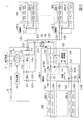
図1は、本発明の第1実施形態に係わる保護システム120を備える太陽光発電システム1の構成例を示す構成図である。この図1に示す太陽光発電システム1は、パワーコンディショナ10と、n個(nは整数)の接続箱100−1、100−2、・・・、100−nと、各接続箱にそれぞれ接続されるストリング200−1、ストリング200−2と、を備えて構成されている。
[First Embodiment]
FIG. 1 is a configuration diagram illustrating a configuration example of a photovoltaic
なお、以下の説明において、接続箱100−1、100−2、・・・、100−nの何れか1つ或いは全てを示す際に「接続箱100」と記載することがある。また、ストリング200−1とストリング200−2との何れか一方或いは両方を示す際に「ストリング200」と記載することがある。
また、図1に示す例では、各接続箱100に、ストリング200−1とストリング200−2との2つのストリングが接続される例を示しているが、各接続箱100には、1つのストリングだけが接続される場合があり、又は、3つ以上のストリングが接続される場合がある。
In the following description, the connection box 100-1, 100-2,..., 100-n may be described as “
Further, in the example shown in FIG. 1, an example is shown in which two strings of strings 200-1 and 200-2 are connected to each
パワーコンディショナ(以下、「PCS」と記載)10は、正極側の給電路L31+と負極側の給電路L31−を介して、接続箱100−1と接続されている。また、PCS10は、正極側の給電路L32+と負極側の給電路L32−とを介して、接続箱100−2と接続されている。また、PCS10は、正極側の給電路L3n+と負極側の給電路L3n−とを介して、接続箱100−nと接続されている。各接続箱100−1、100−2、・・・、100−nは、それぞれに接続されるストリング200において発電された発電電力を集約して、PCS10に供給する。PCS10は、各接続箱100を介してストリング200から供給される発電電力(直流電力)を、DC/AC変換回路により交流電力に変換し、この変換した交流電力を商用系統2などの電源系統へ出力する。
A power conditioner (hereinafter referred to as “PCS”) 10 is connected to the connection box 100-1 via a positive-side power supply path L31 + and a negative-side power supply path L31−. Further, the PCS 10 is connected to the connection box 100-2 via a positive power supply path L32 + and a negative power supply path L32-. The PCS 10 is connected to the connection box 100-n via a positive-side power supply path L3n + and a negative-electrode-side power supply path L3n−. Each of the connection boxes 100-1, 100-2,..., 100-n aggregates the generated power generated in the
PCS10は、インバータ11と、制御装置12と、ダイオードD11、D12、・・・、D1nと、を含んで構成されている。インバータ11は、ストリング200から供給される直流電力を交流電力に変換し、この変換した交流電力を商用系統2などの電源系統へ出力する。制御装置12は、例えば、インバータ11の出力電圧の位相を制御することにより、商用系統2に対して連系させて、インバータ11から商用系統2に交流電力を給電できるようにする。
The PCS 10 includes an
このPCS10において、インバータ11の交流電力の出力側(Out側)には、給電線L1A、L1Bが接続されている。この給電線L1A、L1Bは、例えば、単相交流の給電線である。また、インバータ11の直流電力の入力側(In側)には、正極側の給電線L2+と、負極側の給電線L2−とが接続されている。
In the
なお、以下の説明において、給電線L2+と給電線L2−との何れか一方或いは両方を示す際に「給電線L2」と記載することがある。また、給電路L31+と給電路L31−との何れか一方或いは両方を示す際に「給電路L31」と記載することがある。給電路L32からL3nについても同様である。
また、電線路L101+と、電線路L101−との何れか一方或いは両方を示す際に「電線路L101」と記載することがある。電線路L102についても同様である。また、接続箱100内の接続線L100+と、接続線L100−との何れか一方或いは両方を示す際に「接続線L100」と記載することがある。
In the following description, when one or both of the power supply line L2 + and the power supply line L2- is shown, it may be described as “power supply line L2”. In addition, when one or both of the power supply path L31 + and the power supply path L31- is indicated, it may be described as “power supply path L31”. The same applies to the power supply paths L32 to L3n.
Moreover, when showing either one or both of the electric wire L101 + and the electric wire L101-, it may be described as “electric wire L101”. The same applies to the electrical line L102. In addition, when one or both of the connection line L100 + and the connection line L100- in the
PCS10において、ダイオードD11、D12、・・・、D1nは、逆流防止ダイオードである。この逆流防止ダイオードは、給電路L31からL3nの間における電圧差によりPCS10から接続箱100側へ電流が逆流することを防止する。このダイオードD11、D12、・・・、D1nのそれぞれのカソード端子は、正極側の給電線L2+に共通に接続されている。また、ダイオードD11、D12、・・・、D1nのそれぞれのアノード端子には、各接続箱100に繋がる正極側の給電路L31+、L32+、・・・、L3n+がそれぞれ接続されている。
In the
例えば、ダイオードD11のアノード端子には、接続箱100−1に繋がる給電路L31+が接続されている。ダイオードD12のアノード端子には、接続箱100−2に繋がる給電路L32+が接続されている。ダイオードD1nのアノード端子には、接続箱100−nに繋がる給電路L3n+が接接されている。
また、PCS10において、負極側の給電線L2−には、各接続箱100に繋がる負極側の給電路L31−、L32−、・・・、L3n−が共通に接続されている。また、負極側の給電線L2−は、大地アースGに接地されている。
For example, the power supply path L31 + connected to the connection box 100-1 is connected to the anode terminal of the diode D11. The anode terminal of the diode D12 is connected to a power supply path L32 + connected to the connection box 100-2. The anode terminal of the diode D1n is in contact with the power supply path L3n + connected to the connection box 100-n.
In the
図1に示す太陽光発電システム1において、接続箱100−1、接続箱100−2、・・・、接続箱100−nは、接続されるストリングの数などが異なる場合があるが、基本的な構成が同じ接続箱である。このため、以下の説明では、接続箱100−1を例にとり説明する。
接続箱100−1は、遮断器110と、逆流防止用のダイオードD101、D102と、保護システム120と、を含んで構成されている。また、保護システム120は、温度検出部121、122と、遮断器制御部123と、を含んで構成されている。また、接続箱100−1は、電線路L101、L102が接続される端子台(不図示)と、給電路L31が接続される端子台(不図示)を備えている。
In the photovoltaic
The junction box 100-1 includes a
なお、図1に示す接続箱100−1は、2つのストリング200−1、200−2の電線路L101、L102を並列に接続する例を示しているが、これに限定されない。接続箱100−1は、1つのストリングの電線路だけを接続する接続箱であってもよく、或いは、3つ以上のストリングの電線路を接続する接続箱であってもよい。そして、接続箱100−1に接続されるストリングの数に応じて、接続箱が備える逆流防止ダイオードの数や、端子台の極数等が変化する。 In addition, although the connection box 100-1 shown in FIG. 1 has shown the example which connects the electric wires L101 and L102 of two strings 200-1 and 200-2 in parallel, it is not limited to this. The connection box 100-1 may be a connection box that connects only one string electric wire, or may be a connection box that connects three or more string electric wires. And according to the number of strings connected to the connection box 100-1, the number of backflow prevention diodes provided in the connection box, the number of poles of the terminal block, and the like change.
この接続箱100−1において、遮断器110は、例えば、直流用の配線用遮断器(Molded Case Circuit Breaker; MCCB)である。この遮断器110は、予め設定した整定電流値以上の電流が流れる場合に、所定の限時特性を持ってトリップ(導通を遮断)する。また、遮断器110は、短絡電流のように非常に大きな電流が流れる場合、瞬時(例えば、数10msec以内)にトリップする。
また、遮断器110は、外部から操作されてトリップするように構成されている。例えば、遮断器110は、後述するように、外部から操作されてトリップするトリップボタンを備えている。遮断器制御部123は、遮断器110のトリップボタンを操作することにより、遮断器110を強制的にトリップさせる。
In this connection box 100-1, the
The
接続箱100−1において、ダイオードD101、D102は、逆流防止ダイオードであり、ストリング200−1の出力電圧とストリング200−2の出力電圧との差による、ストリング200−1とストリング200−2との間の電流の逆流を防止する。ダイオードD101のアノード端子は、電線路L101+に接続され、この電線路L101+を介して、ストリング200−1の正極端子(+)に接続されている。ダイオードD102のアノード端子は、電線路L102+に接続され、この電線路L102+を介して、ストリング200−2の正極端子(+)に接続されている。 In the connection box 100-1, diodes D101 and D102 are backflow prevention diodes, and the strings 200-1 and 200-2 are caused by the difference between the output voltage of the string 200-1 and the output voltage of the string 200-2. Prevent reverse current flow between them. The anode terminal of the diode D101 is connected to the electric line L101 +, and is connected to the positive terminal (+) of the string 200-1 via the electric line L101 +. The anode terminal of the diode D102 is connected to the electric line L102 +, and is connected to the positive terminal (+) of the string 200-2 via the electric line L102 +.
また、ダイオードD101のカソード端子と、ダイオードD102のカソード端子とは、接続線L100+に共通に接続されている。この接続線L100+は、遮断器110の一方の端子a1に接続され、遮断器110の他方の端子b1は、給電路L31+を介して、PCS10に接続されている。
The cathode terminal of the diode D101 and the cathode terminal of the diode D102 are commonly connected to the connection line L100 +. The connection line L100 + is connected to one terminal a1 of the
また、ストリング200−1の負極側の電線路L101−と、ストリング200−2の負極側の電線路L102−とは、接続箱100−1内の負極側の接続線L100−に共通に接続されている。そして、接続線L100−は、遮断器110の一方の端子a2に接続され、遮断器110の他方の端子b2は、給電路L31−を介して、PCS10に接続されている。
Further, the negative electrode side electric wire L101- of the string 200-1 and the negative electrode side electric wire L102- of the string 200-2 are commonly connected to the negative electrode side connection line L100- in the connection box 100-1. ing. The connection line L100- is connected to one terminal a2 of the
また、接続箱100−1において、電線路L101+の絶縁被覆の外周部には、温度検出部121が取り付けられ、電線路L102+の絶縁被覆の外周部には、温度検出部122取り付けられている。この温度検出部121、122は、例えば、サーミスタやサーモスタット等であり、電線路L101+、L102+のそれぞれの表面温度を検出する。例えば、温度検出部121は、電線路L101+の温度が所定の閾値温度に達したか否か示す温度検出信号Ts1を、遮断器制御部123に出力する。温度検出部122についても同様であり、温度検出部122は、電線路L102+の温度が所定の閾値温度に達したか否かを示す温度検出信号Ts2を、遮断器制御部123に出力する。
Further, in the junction box 100-1, the
遮断器制御部123は、遮断器110の導通を強制的にトリップ(遮断)させる制御部である。遮断器制御部123は、温度検出部121、122から温度検出信号Ts1、Ts2を入力し、電線路L101、L102の温度が予め定めた閾値温度に達したことを検出した場合、遮断器110を強制的にトリップさせる。
The circuit
また、図2は、保護システム120における保護動作を説明する第1の説明図である。この図2で示す例は、接続箱100−1とPCS10とを接続する給電路L31の位置Sgにおいて、正極側の給電路L31+と、負極側の給電路L31−との間で短絡故障が発生した例を示している。また、この図2に示す例は、短絡故障により、給電路L31+と給電路L31−との間に電流Igが流れるが、この電流Igの電流値が、接続箱100−1内の遮断器110をトリップさせる電流値まで達していない例を示している。
FIG. 2 is a first explanatory diagram for explaining a protection operation in the
この短絡故障の場合、電流Igは、ストリング200−1から流れる電流Ig1と、ストリング200−2から流れる電流Ig2と、を合計した電流になる。この電流Ig、Ig1、Ig2の電流値は、ストリング200−1、200−2のそれぞれの出力電圧と、ストリング200−1、200−2のそれぞれの内部インピーダンスと、電線路L101の線路インピーダンスと、給電路L31の線路インピーダンス等に応じて決まる。 In the case of this short-circuit fault, the current Ig is the sum of the current Ig1 flowing from the string 200-1 and the current Ig2 flowing from the string 200-2. The current values of the currents Ig, Ig1, and Ig2 are the output voltages of the strings 200-1 and 200-2, the internal impedances of the strings 200-1 and 200-2, the line impedance of the electric line L101, It is determined according to the line impedance and the like of the feed line L31.
そして、例えば、ストリング200−1から流れる電流Ig1が、電線路L101+を最高許容温度(例えば、80℃)を超えて発熱させる電流値以上である場合、短絡故障が発生した時点から、電線路L101+は発熱を開始し、電線路L101の温度が次第に上昇する。
そして、電線路L101+の温度が所定の閾値温度(例えば、80℃)に達したことが温度検出部121により検出された場合、温度検出部121は、電線路L101+の温度が閾値温度に達したことを示す温度検出信号Ts1を、遮断器制御部123に出力する。遮断器制御部123は、電線路L101+の温度が閾値温度に達したことを示す温度検出信号Ts1を温度検出部121から入力すると、遮断器110を強制的にトリップさせる。
For example, when the current Ig1 flowing from the string 200-1 is equal to or higher than the current value that causes the electric wire L101 + to generate heat exceeding the maximum allowable temperature (for example, 80 ° C.), the electric wire L101 + from the time when the short-circuit failure occurs. Starts to generate heat, and the temperature of the electrical line L101 gradually increases.
When the
このように、保護システム120では、電線路L101に最高許容温度を超えて発熱させる電流Ig1が流れるが遮断器110がトリップしない場合に、電線路L101の温度を検出して、遮断器110を強制的にトリップさせることができる。
なお、電線路L102+に流れる電流Ig2が、電線路L102+の温度を最高許容温度を超えて発熱させる電流値以上である場合も同様である。
Thus, in the
The same applies to the case where the current Ig2 flowing through the electrical line L102 + is equal to or higher than the current value that causes the temperature of the electrical line L102 + to exceed the maximum allowable temperature.
また、図3は、保護システム120における保護動作を説明する第2の説明図である。
なお、図3に示す例では、図面の見易さのために、PCS10内の交流給電線L1A及びL1Bを単線の給電線L1で示している。また、給電線L2と、給電路L31からL3nと、電線路L101、L102と、接続箱100内の接続線L100とは、正極側の電線や電路を示しており、負極側の電線や電路は省略されている。
FIG. 3 is a second explanatory diagram for explaining the protection operation in the
In the example shown in FIG. 3, the AC power supply lines L <b> 1 </ b> A and L <b> 1 </ b> B in the
この図3に示す例は、PCS10内において、ダイオードD11が故障して短絡状態になるとともに、接続箱100−1内において、ダイオードD101が故障して短絡状態になる例である。また、PCS10内の給電線L2の電圧が、接続箱100−1に接続されるストリング200−1の出力電圧よりも高く、PCS10側からストリング200−1側に電流Icが流れる例である。また、この電流Icの電流値が、遮断器110をトリップさせる電流値まで達していない例である。
この故障の場合、電流Icの電流値は、PCS10内の給電線L2の電圧と、ストリング200−1の出力電圧と、ストリング200−1の内部インピーダンスと、電線路L101の線路インピーダンスと、給電路L31の線路インピーダンス等に応じて決まる。
The example shown in FIG. 3 is an example in which the diode D11 fails in the
In the case of this failure, the current value of the current Ic is the voltage of the power supply line L2 in the
そして、例えば、ストリング200−1に流れる電流Icが、電線路L101の温度を最高許容温度を超えて発熱させる電流値以上である場合、故障が発生した時点から、電線路L101は発熱を開始し、電線路L101の温度が次第に上昇する。
そして、電線路L101の温度が所定の閾値温度に達したことが温度検出部121により検出された場合、温度検出部121は、電線路L101の温度が閾値温度に達したことを示す温度検出信号Ts1を、遮断器制御部123に出力する。遮断器制御部123は、電線路L101の温度が閾値温度に達したことを示す温度検出信号Ts1を温度検出部121から入力すると、遮断器110を強制的にトリップさせる。
For example, when the current Ic flowing through the string 200-1 is equal to or higher than a current value that causes the temperature of the electric wire L101 to exceed the maximum allowable temperature and generate heat, the electric wire L101 starts to generate heat from the time when the failure occurs. The temperature of the electric line L101 gradually increases.
When the
このように、保護システム120では、電線路L101に最高許容温度を超えて発熱させる電流Icが流れるが遮断器110がトリップしない場合に、電線路L101の温度を検出して、遮断器110を強制的にトリップさせることができる。
なお、ダイオードD11とダイオードD102とが故障した場合についても同様である。
As described above, in the
The same applies to the case where the diode D11 and the diode D102 fail.
以上、説明したように、本発明の保護システム120は、並列に接続された複数のストリング200を有する太陽光発電システム1の保護システム120であって、複数のストリング200から当該複数のストリング200を並列に接続する接続線L100(接続点)までの電線路L101、L102の温度を検出する温度検出部121、122と、検出された温度に応じて、接続線L100と給電路L31(接続点より負荷側にある回路)との間に設けた遮断器110の導通状態を制御する遮断器制御部123と、を備える。
このような構成の保護システム120では、複数のストリング200までの電線路L101、L102の温度を検出する。そして、保護システム120は、電線路L101、L102が閾値温度を超えて発熱する場合に、遮断器110をトリップさせて、接続箱100−1と、PCS10との間の接続を遮断する。
As described above, the
In the
これにより、本実施形態の保護システム120は、太陽光発電システム1において短絡故障等が発生した場合に、電線路L101、L102や接続箱100−1が受ける影響を低減することができる。
なお、図1に示す例において、接続箱100−1、100−2、・・・、100−nの全てが、温度検出部121、122と、遮断器制御部123を備える必要はなく、例えば、所定の接続箱100のみが、保護システム120を備えるようにしてもよい。
また、温度検出部121、122は、接続箱100の内部に設備することができる他、接続箱100の外部に設けることもできる。
Thereby, the
In the example shown in FIG. 1, all of the connection boxes 100-1, 100-2,..., 100-n do not need to include the
Moreover, the
[第2実施形態]
図4は、本発明の第2実施形態に係わる保護システム120Aの構成例を示す構成図である。
なお、図4に示す例では、図3に示す例と同様に、図面の見易さのために、交流給電線L1を単線で示している。また、給電線L2と、給電路L31からL3nと、電線路L101、L102と、接続線L100とは、正極側の電線や電路を示しており、負極側の電線や電路は省略されている。
[Second Embodiment]
FIG. 4 is a configuration diagram showing a configuration example of a
In the example shown in FIG. 4, like the example shown in FIG. 3, the AC power supply line L1 is shown as a single line for the sake of easy viewing. In addition, the power supply line L2, the power supply lines L31 to L3n, the electric lines L101 and L102, and the connection line L100 indicate positive-side electric wires and electric circuits, and the negative-side electric wires and electric circuits are omitted.
この図4に示す接続箱100−1Aでは、遮断器110として、ブレーカ(配線用遮断器)111を用いている。このブレーカ111は、トリップボタン112を備えている。このトリップボタン112は、ブレーカ111を強制的にトリップさせるボタンである。
また、ブレーカ111は、補助接点113を備えている。この補助接点113は、ブレーカ111のON、OFF(導通、遮断)動作に連動する。例えば、補助接点113は、ブレーカ111のON状態の場合にONになり、ブレーカ111のOFF状態の場合にOFFになる。
また、保護システム120Aでは、電線路L101、L102のそれぞれの温度を検出する温度検出部として、サーモスタット121A、122Bを用いている。また、保護システム120Aでは、遮断器制御部123として、ソレノイド124と、ソレノイド電源部127と、補助接点113と、を用いている。
In the junction box 100-1A shown in FIG. 4, a breaker (wiring circuit breaker) 111 is used as the
In addition, the
Further, in the
この図4に示す接続箱100−1A内の保護システム120Aは、電線路L101、L102のそれぞれの温度をサーモスタット121A、122Aで検出する。サーモスタット121Aは、電線路L101の絶縁被覆の外周部に取り付けられ、サーモスタット121Aは、電線路L102の絶縁被覆の外周部に取り付けられている。
The
サーモスタット121Aは、例えば、電線路L101の温度が所定の閾値温度(例えば、80℃)よりも低い場合に、OFF(開放)になり、閾値温度に達した場合に、ON(接続)になるスイッチ動作を行う。また、同様に、サーモスタット122Aは、例えば、電線路L102の温度が所定の閾値温度よりも低い場合に、OFFになり、閾値温度に達した場合に、ONになるスイッチ動作を行う。
The
遮断器制御部123は、ソレノイド124と、ソレノイド電源部127と、補助接点113と、を含んで構成されている。ソレノイド124は、ソレノイド電源部127によりコイル125に通電が行われる場合、プランジャ126を矢印Aの方向に移動させる。そして、プランジャ126は、矢印Aの方向に移動することにより、先端部126Aをトリップボタン112の先端部112Aに押し当て、トリップボタン112を矢印A方向に押し込む。上記のトリップボタン112の移動方向である「矢印Aの方向」は、ブレーカ111をトリップさせるように作用する方向である。これにより、ブレーカ111がトリップする。
The circuit
また、ソレノイド124は、コイルへの通電が停止された場合、不図示のバネ機構により矢印Bの方向に移動し、所定の規制位置まで引き戻される。なお、ソレノイド124の正極側の+端子と、ソレノイド124の負極側の−端子との間には、フライホイールダイオードFDが図に示す向きに接続されている。
ソレノイド電源部127は、例えば、接続線L100から電力の供給を受けて、ソレノイド124のコイル125を駆動する直流電源である。また、例えば、このソレノイド電源部127は、接続線L100から供給される電力により充電される蓄電池(不図示)を供え、この蓄電池によりソレノイド124のコイル125に通電を行うようにしてもよい。
Further, when energization of the coil is stopped, the
The solenoid
そして、この接続箱100−1Aにおいて、ソレノイド電源部127の正極側の+端子は、配線W1を介して、ブレーカ111の補助接点113の一方の端子c1に接続され、補助接点113の他方の端子c2は、配線W2を介してソレノイド124の正極側の+端子に接続されている。ソレノイド124の負極側の−端子は、配線W3を介して、サーモスタット121Aの一方の端子bと、サーモスタット122Aの一方の端子bと、に共通に接続されている。また、サーモスタット121Aの他方の端子aと、サーモスタット122Aの他方の端子aとは、配線W4に共通に接続され、この配線W4は、ソレノイド電源部127の負極側の−端子に接続されている。
In the connection box 100-1A, the positive terminal on the positive side of the solenoid
上記構成の接続箱100−1Aにおいて、例えば、電線路L101の温度が上昇し、サーモスタット121Aの装着された位置における温度が所定の閾値温度に達すると、サーモスタット121AがOFF状態からON状態に切り替わる。また、同様に、電線路L102の温度が上昇し、サーモスタット122Aの装着された位置における温度が所定の閾値温度に達すると、サーモスタット122AがOFF状態からON状態に切り替わる。
In the connection box 100-1A having the above configuration, for example, when the temperature of the electric line L101 rises and the temperature at the position where the
そして、例えば、ブレーカ111がON状態(補助接点113がON状態)の場合において、電線路L101が発熱し、サーモスタット121AがON状態になるとする。この場合、「ソレノイド電源部127の+端」→「補助接点113」→「ソレノイド124のコイル125」→「サーモスタット121A」→「ソレノイド電源部127の−端子」の経路で電流Idが流れる。そして、ソレノイド124のコイル125に電流Idが流れることにより、ソレノイド124は、プランジャ126を矢印Aの方向に押し出す。そして、プランジャ126の先端部126Aがトリップボタン112の先端部112Aを、矢印Aの方向に押し込むことにより、ブレーカ111がトリップする。そして、ブレーカ111がトリップすると、補助接点113がOFF状態になり、ソレノイド電源部127からソレノイド124のコイル125への通電が停止される。これにより、プランジャ126は、元の位置に復帰する。
For example, when the
以上、説明したように、保護システム120Aにおいて、遮断器制御部123は、電線路L101、L102の温度が予め定めた温度に達した場合にコイル125に電流Idが流れるように構成されたソレノイド124を備え、ソレノイド124がコイル125の通電に応じてブレーカ111(遮断器)をトリップ(遮断)させる。
As described above, in the
このような構成の保護システム120Aでは、複数のストリング200に繋がる電線路L101、L102の温度を検出し、電線路L101、L102が発熱し閾値温度に達する場合に、ソレノイド124を用いて、ブレーカ111(遮断器)をトリップさせる。
これにより、保護システム120Aは、太陽光発電システム1において短絡故障等が発生した場合に、電線路L101、L102や接続箱100−1Aが受ける影響を低減することができる。
また、本実施形態の保護システム120Aは、運用中の太陽光発電設備を停止させることなく、本保護システム120Aを接続箱100−1Aに実装することができる。
In the
Thereby, 120 A of protection systems can reduce the influence which electric line L101, L102 and the connection box 100-1A receive when a short circuit failure etc. generate | occur | produce in the solar
Moreover, the
[第3実施形態]
また、図5は、本発明の第3実施形態に係わる保護システム120Bの構成例を示す構成図である。なお、この図5に示す例は、図3に示す例と同様に、交流給電線L1を単線で示している。また、給電線L2と、給電路L31からL3nと、電線路L101、L102と、接続箱100内の接続線L100とは、正極側の電線や電路を示しており、負極側の電線や電路は省略されている。
[Third Embodiment]
FIG. 5 is a block diagram showing a configuration example of a
この図5に示す太陽光発電システム1Bは、図1に示す太陽光発電システム1と比較すると、図5に示す接続箱100−1B内に、電線路用遮断器110Aと、電線路用遮断器110Bと、を新たに追加した点が異なる。他の構成は、図1に示す太陽光発電システム1と同様である。このため、同一の構成部分には同一の符号を付し、重複する説明は省略する。
Compared with the photovoltaic
図5に示す接続箱100−1Bにおいて、電線路用遮断器110Aは、ストリング200−1と電線路L101とを保護する直流用の過電流遮断器である。また、電線路用遮断器110Bは、ストリング200−2と電線路L102とを保護する直流用の過電流遮断器である。
この電線路用遮断器110A、110Bは、予め設定した整定電流値以上の電流が流れる場合に、所定の限時特性を持ってトリップする。また、電線路用遮断器110A、110Bは、短絡電流のように非常に大きな電流が流れる場合、瞬時(例えば、数10msec以内)にトリップする。また、電線路用遮断器110A、110Bは、外部から操作されてトリップするように構成されている。例えば、電線路用遮断器110A、110Bは、図4で示したブレーカ111と同じようにトリップボタン112を備える。そして、遮断器制御部123Bは、トリップボタン112を操作することにより電線路用遮断器110A、110Bを強制的にトリップさせることができる。
In the junction box 100-1B shown in FIG. 5, the
The
ストリング200−1に繋がる電線路L101は、接続箱100−1B内の電線路用遮断器110Aの一方の端子aに接続され、電線路用遮断器110Aの他方の端子bは、ダイオードD101のアノード端子に接続される。また、ストリング200−2に繋がる電線路L102は、接続箱100−1B内の電線路用遮断器110Bの一方の端子aに接続され、電線路用遮断器110Bの他方の端子bは、ダイオードD102のアノード端子に接続される。
そして、電線路L101の温度が所定の閾値温度を超えたことが温度検出部121により検出された場合、遮断器制御部123Bは、電線路用遮断器110Aを強制的にトリップさせる。また、電線路L102の温度が所定の閾値温度を超えたことが温度検出部122により検出された場合、遮断器制御部123Bは、電線路用遮断器110Bを強制的にトリップさせる。
なお、遮断器制御部123Bは、第1実施形態の遮断器制御部123と同様にして、PCS10側の給電路L31に繋がる遮断器110を強制的にトリップさせる機能も備えている。
The electric line L101 connected to the string 200-1 is connected to one terminal a of the
When the
The circuit
この保護システム120Bにおいて、例えば、電線路用遮断器110A、110Bを遮断する第1の閾値温度と、遮断器110を遮断する第2の閾値温度とを異なるように設定することができる。例えば、第1の閾値温度(例えば、70℃)よりも第2の閾値温度(例えば、80℃)を高くなるようにする。
なお、この場合、温度検出部121、122は、温度検出信号Ts1、Ts2として、電線路L101、L102の温度情報を遮断器制御部123Bに出力する。遮断器制御部123Bでは、電線路L101、L102の温度情報に基づいて、電線路L101、L102のそれぞれの温度が、第1の閾値温度と、第2の閾値温度とに達しているか否かを判定する。
そして、例えば、電線路L101が発熱して温度が上昇し第1の閾値温度に達した場合、遮断器制御部123Bは、電線路用遮断器110Aを強制的にトリップさせる。そして、電線路用遮断器110Aを強制的にトリップさせた後、電線路L101の温度がさらに上昇し第2の閾値温度に達した場合、遮断器制御部123Bは、遮断器110を遮断する。
In this
In this case, the
For example, when the electric line L101 generates heat and the temperature rises and reaches the first threshold temperature, the circuit
これにより、接続箱100−1Bでは、電線路L101の系統のみに故障が発生して電線路L101のみが発熱する場合、電線路用遮断器110Aを強制的にトリップさせて、電線路L101の系統を切り離すことができる。このため、接続箱100−1Bでは、健全な電線路L102の系統からPCS10への発電電力の供給を継続させることができる。
また、電線路L102の系統のみに故障が発生して電線路L102のみが発熱する場合も同様であり、接続箱100−1Bでは、電線路用遮断器110Bを強制的にトリップさせて、電線路L102の系統を切り離すことができる。そして、接続箱100−1Bでは、健全な電線路L101の系統からPCS10への発電電力の供給を継続させることができる。
Thereby, in the junction box 100-1B, when a failure occurs only in the system of the electrical line L101 and only the electrical line L101 generates heat, the
The same applies to the case where a failure occurs only in the system of the electrical line L102 and only the electrical line L102 generates heat. In the connection box 100-1B, the
また、図6は、保護システム120Bにおける保護動作を説明する説明図である。この図6に示す例は、接続箱100−1内において、ダイオードD101が故障してこのダイオードD101が短絡状態になる例である。そして、ストリング200−2の発電電圧が、ストリング200−1の発電電圧よりも高く、ストリング200−2側からストリング200−1に電流Isが流れる例である。また、この電流Isの電流値が、電線路用遮断器110Aをトリップさせる電流値まで達していない例である。
FIG. 6 is an explanatory diagram for explaining the protection operation in the
そして、例えば、ストリング200−2からストリング200−1に流れる電流Isが、電線路L101を最高許容温度(例えば、80℃)を超えて発熱させる電流値以上である場合、ダイオードD101の故障が発生した時点から、電線路L101は発熱を開始し、電線路L101の温度が次第に上昇する。
そして、電流Isにより電線路L101が発熱し、電線路L101の温度が所定の第1の閾値温度(例えば、70℃)を超えたことが温度検出部121により検出された場合、遮断器制御部123Bは、電線路用遮断器110Aを強制的にトリップさせる。
これにより、電線路L101に電流Isが流れて発熱するが、この電流Isの電流値が電線路用遮断器110Aをトリップさせる電流に達していない場合でも、遮断器制御部123Bは、電線路用遮断器110Aを強制的にトリップさせることができる。
ダイオードD102が故障して電線路L102が発熱する場合も同様である。
For example, when the current Is flowing from the string 200-2 to the string 200-1 is equal to or higher than a current value that causes the electric wire L101 to generate heat exceeding the maximum allowable temperature (for example, 80 ° C.), a failure of the diode D101 occurs. From this point, the electric wire L101 starts to generate heat, and the temperature of the electric wire L101 gradually increases.
When the
As a result, the current Is flows through the electric line L101 to generate heat, but even when the current value of the current Is has not reached the electric current for tripping the
The same applies when the diode D102 breaks down and the electrical line L102 generates heat.
以上、説明したように、保護システム120Bにおいて、遮断器制御部123Bは、温度検出部121、122により検出された温度に応じて、複数のストリング200の電線路L101、L102のそれぞれと接続線L100(接続点)との間に設けた電線路用遮断器110A、110Bの導通状態を制御する。
As described above, in the
このように、保護システム120Bでは、例えば、電線路L101に最高許容温度を超えて発熱させる電流Isが流れるが電線路用遮断器110Aがトリップしない場合、電線路L101の温度を検出して、電線路用遮断器110Aを強制的にトリップさせることができる。同様に、保護システム120Bでは、電線路L102に最高許容温度を超えて発熱させる電流が流れるが電線路用遮断器110Bがトリップしない場合、電線路L102の温度を検出して、電線路用遮断器110Bを強制的にトリップさせることができる。
これにより、太陽光発電システム1Bにおいて短絡故障等が発生した場合に、電線路L101、L102や接続箱100−1Bが受ける影響を低減することができる。
In this way, in the
Thereby, when a short circuit failure etc. occur in solar
以上、本発明の実施の形態について説明したが、本発明の保護システムは、上述の図示例にのみに限定されるものではなく、本発明の要旨を逸脱しない範囲内において種々変更を加え得ることは勿論である。
例えば、上記の実施形態に示した温度検出部(サーモスタット)は、1つのストリング200の電線路にそれぞれ設ける場合を例示したが、複数のストリング200の電線路に対して1つの温度検出部(サーモスタット)を設けるように構成してもよい。
As mentioned above, although embodiment of this invention was described, the protection system of this invention is not limited only to the above-mentioned illustration example, A various change can be added in the range which does not deviate from the summary of this invention. Of course.
For example, although the temperature detection unit (thermostat) shown in the above-described embodiment has been illustrated as being provided in the electric wires of one
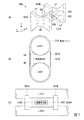
図7は、複数のストリング200の電線路に1つの温度検出部を設ける構成の説明図である。
図7(A)は、2つの電線路L101+、L102+に対して1つの温度検出部を設ける場合に使用する装着具300の概略構成を示している。
図7(B)は、図7(A)において装着具300をX方向から見た図を示している。この図7(B)では、2つの電線路L101+、L102+が装着具300に取り付けられた状態を示し、また、電線路L101+、L102+を断面図で示している。
図7(C)は、図7(A)において、装着具300をY方向から見た図を示している。但し、図7(C)では、図面の見易さのために支柱302を省略している。
FIG. 7 is an explanatory diagram of a configuration in which one temperature detection unit is provided in the electric wires of the plurality of
FIG. 7A shows a schematic configuration of the mounting
FIG. 7B shows a view of the wearing
FIG. 7C shows a view of the wearing
図7(A)に示すように、装着具300は、2枚の電線固定板301A、301Bを有している。この電線固定板301A、301Bは、温度検出部121Bに対する電線路L101+、L102+の位置を規制する際に利用される凹部m1、m2を有している。また、電線固定板301A、301Bは、4本平行に設けられる支柱302により対向する位置に固定されている。また、この装着具300の電線固定板301Aと電線固定板301Bとの間の中間の部分には、4本の平行な支柱302に囲まれるようにして、温度検出部121Bが配置されている。
そして、1つの電線路の側面が、電線固定板301Aの凹部m1と電線固定板301Bの凹部m1とに、2箇所で押し付けられることにより、この電線路の温度検出部121Bに対する位置が規制される。電線固定板301A、301Bの凹部m2についても同様である。
As shown in FIG. 7A, the mounting
And the position with respect to the
そして、図7(B)に示すように、各電線路L101+、L102+は、それぞれの側面が電線固定板301A、301Bの凹部m1、m2にそれぞれ押し付けられ、温度検出部121Bに対する位置が規制される。そして、この位置が規制された状態で、各電線路L101+、L102+は、結束バンド310により装着具300に固定される。
その後、図7(C)に示すように、電線路L101+、L102+の側面(装着具300に対向する側面)と温度検出部121Bとの間には、熱伝導性の充填剤が充填される。これにより、装着具300では、各電線路L101+、L102+と温度検出部121Bとの間の熱伝導率を高めるようにしている。
なお、この図7では、2つのストリング200の電線路L101+、L102+に対して1つの温度検出部121Bを設ける例を示しているが、3つ以上のストリング200の電線路に対して1つの温度検出部を設ける場合も同様である。
And as shown in FIG.7 (B), each electric wire path L101 +, L102 + each presses each recessed part m1, m2 of electric
Thereafter, as shown in FIG. 7C, a heat conductive filler is filled between the side surfaces (side surfaces facing the mounting tool 300) of the electric wires L101 + and L102 + and the
FIG. 7 shows an example in which one
図7のように構成することにより、保護システム120(120A、120B)は、温度検出部の必要数を低減することができる。 By configuring as shown in FIG. 7, the protection system 120 (120A, 120B) can reduce the required number of temperature detection units.
1,1B・・・太陽光発電システム、2・・・商用系統、
10・・・パワーコンディショナ(PCS)、
100−1,100−2,100−n・・・接続箱、
100−1A,100−1B・・・接続箱、
110・・・遮断器、110A,110B・・・電線路用遮断器、
111・・・ブレーカ、112・・・トリップボタン、
120,120A,120B・・・保護システム、
121,121B,122・・・温度検出部、
121A,122A・・・サーモスタット(温度検出部)、
123,123B・・・遮断器制御部、
124・・・ソレノイド、125・・・コイル、
126・・・プランジャ、127・・・ソレノイド電源部、
200,200−1,200−2・・・太陽電池ストリング(ストリング)、
L100・・・接続線(接続点)、L101,L102・・・電線路、
L31,L32,L3n・・・給電路
1, 1B ... Solar power generation system, 2 ... Commercial system,
10 ... Power conditioner (PCS),
100-1, 100-2, 100-n ... connection box,
100-1A, 100-1B ... connection box,
110 ... circuit breaker, 110A, 110B ... electric circuit breaker,
111 ... Breaker, 112 ... Trip button,
120, 120A, 120B ... protection system,
121, 121B, 122... Temperature detector,
121A, 122A ... thermostat (temperature detector),
123, 123B ... circuit breaker control unit,
124 ... Solenoid, 125 ... Coil,
126 ... plunger, 127 ... solenoid power supply,
200, 200-1, 200-2 ... solar cell string (string),
L100 ... connection line (connection point), L101, L102 ... electric line,
L31, L32, L3n ... Feeding path
Claims (5)
複数のストリングから当該複数のストリングを並列に接続する接続点までの電線路の温度を検出する温度検出部と、
前記検出された温度に応じて、前記接続点と前記接続点より負荷側にある回路との間に設けた遮断器の導通状態を制御する遮断器制御部と、
を備えることを特徴とする保護システム。 A photovoltaic system protection system having a plurality of strings connected in parallel,
A temperature detection unit that detects the temperature of the electric line from a plurality of strings to a connection point that connects the plurality of strings in parallel;
According to the detected temperature, a circuit breaker control unit for controlling a conduction state of a circuit breaker provided between the connection point and a circuit on the load side from the connection point;
A protection system comprising:
を備え、
前記遮断器制御部は、
前記電線路の温度が予め定めた温度に達した場合に前記遮断器を遮断させる
ことを特徴とする請求項1に記載の保護システム。 A circuit breaker whose conduction state is controlled according to the control of the circuit breaker control unit,
The circuit breaker control unit
The protection system according to claim 1, wherein the circuit breaker is interrupted when a temperature of the electric wire reaches a predetermined temperature.
前記電線路の温度が予め定めた温度に達した場合にコイルに電流が流れるように構成されたソレノイドを備え、
前記ソレノイドが前記コイルの通電に応じて前記遮断器を遮断させる
ことを特徴とする請求項1又は請求項2に記載の保護システム。 The circuit breaker control unit
Comprising a solenoid configured to allow current to flow through the coil when the temperature of the electrical line reaches a predetermined temperature;
The protection system according to claim 1 or 2, wherein the solenoid interrupts the circuit breaker in response to energization of the coil.
前記温度検出部により検出された温度に応じて、前記複数のストリングの電線路のそれぞれと前記接続点との間に設けた電線路用遮断器の導通状態を制御する
ことを特徴とする請求項1から3の何れか1項に記載の保護システム。 The circuit breaker control unit
The electrical connection circuit breaker provided between each of the plurality of string electrical lines and the connection point is controlled in accordance with the temperature detected by the temperature detection unit. The protection system according to any one of 1 to 3.
複数のストリングから当該複数のストリングを並列に接続する接続点までの電線路の温度を検出する過程と、
前記検出された温度に応じて、前記接続点と前記接続点より負荷側にある回路との間に設けた遮断器の導通状態を制御する過程と
を含むことを特徴とする保護方法。 A method for protecting a photovoltaic system having a plurality of strings connected in parallel,
A process of detecting the temperature of the electrical line from a plurality of strings to a connection point connecting the plurality of strings in parallel;
And a step of controlling a conduction state of a circuit breaker provided between the connection point and a circuit located on a load side from the connection point in accordance with the detected temperature.
Priority Applications (1)
| Application Number | Priority Date | Filing Date | Title |
|---|---|---|---|
| JP2015086685A JP6581799B2 (en) | 2015-04-21 | 2015-04-21 | Protection system and protection method |
Applications Claiming Priority (1)
| Application Number | Priority Date | Filing Date | Title |
|---|---|---|---|
| JP2015086685A JP6581799B2 (en) | 2015-04-21 | 2015-04-21 | Protection system and protection method |
Publications (2)
| Publication Number | Publication Date |
|---|---|
| JP2016208635A true JP2016208635A (en) | 2016-12-08 |
| JP6581799B2 JP6581799B2 (en) | 2019-09-25 |
Family
ID=57488075
Family Applications (1)
| Application Number | Title | Priority Date | Filing Date |
|---|---|---|---|
| JP2015086685A Expired - Fee Related JP6581799B2 (en) | 2015-04-21 | 2015-04-21 | Protection system and protection method |
Country Status (1)
| Country | Link |
|---|---|
| JP (1) | JP6581799B2 (en) |
Cited By (5)
| Publication number | Priority date | Publication date | Assignee | Title |
|---|---|---|---|---|
| JP2019106824A (en) * | 2017-12-14 | 2019-06-27 | オムロン株式会社 | Solar battery array testing system, power conditioner, and solar battery array testing method |
| WO2019135488A1 (en) * | 2018-01-08 | 2019-07-11 | 삼성에스디아이(주) | Emergency disconnect circuit for energy storage system |
| JP2019161809A (en) * | 2018-03-12 | 2019-09-19 | オムロン株式会社 | Solar cell array inspection system, power conditioner, and solar cell array inspection method |
| JPWO2019021449A1 (en) * | 2017-07-28 | 2019-12-12 | 東芝三菱電機産業システム株式会社 | Photovoltaic power generation system and grounding method thereof |
| WO2021038915A1 (en) * | 2019-08-27 | 2021-03-04 | オムロン株式会社 | Photovoltaic power generation network cut-off unit and photovoltaic power generation network cut-off system provided with same |
Citations (5)
| Publication number | Priority date | Publication date | Assignee | Title |
|---|---|---|---|---|
| JP2007124809A (en) * | 2005-10-28 | 2007-05-17 | Mt Technology Kk | Breaker control system and breaker or limiter |
| JP2011176155A (en) * | 2010-02-25 | 2011-09-08 | Kyocera Corp | Solar power generation apparatus |
| JP2012160667A (en) * | 2011-02-02 | 2012-08-23 | Toshiba Corp | Photovoltaic power generation system |
| JP2013247787A (en) * | 2012-05-25 | 2013-12-09 | Toshiba Corp | Photovoltaic power generation system and short circuit current detector |
| JP2014052325A (en) * | 2012-09-10 | 2014-03-20 | Sharp Corp | Photovoltaic power generation system |
-
2015
- 2015-04-21 JP JP2015086685A patent/JP6581799B2/en not_active Expired - Fee Related
Patent Citations (5)
| Publication number | Priority date | Publication date | Assignee | Title |
|---|---|---|---|---|
| JP2007124809A (en) * | 2005-10-28 | 2007-05-17 | Mt Technology Kk | Breaker control system and breaker or limiter |
| JP2011176155A (en) * | 2010-02-25 | 2011-09-08 | Kyocera Corp | Solar power generation apparatus |
| JP2012160667A (en) * | 2011-02-02 | 2012-08-23 | Toshiba Corp | Photovoltaic power generation system |
| JP2013247787A (en) * | 2012-05-25 | 2013-12-09 | Toshiba Corp | Photovoltaic power generation system and short circuit current detector |
| JP2014052325A (en) * | 2012-09-10 | 2014-03-20 | Sharp Corp | Photovoltaic power generation system |
Cited By (8)
| Publication number | Priority date | Publication date | Assignee | Title |
|---|---|---|---|---|
| JPWO2019021449A1 (en) * | 2017-07-28 | 2019-12-12 | 東芝三菱電機産業システム株式会社 | Photovoltaic power generation system and grounding method thereof |
| JP2019106824A (en) * | 2017-12-14 | 2019-06-27 | オムロン株式会社 | Solar battery array testing system, power conditioner, and solar battery array testing method |
| JP6992473B2 (en) | 2017-12-14 | 2022-01-13 | オムロン株式会社 | Solar cell array inspection system, power conditioner and solar cell array inspection method |
| WO2019135488A1 (en) * | 2018-01-08 | 2019-07-11 | 삼성에스디아이(주) | Emergency disconnect circuit for energy storage system |
| JP2019161809A (en) * | 2018-03-12 | 2019-09-19 | オムロン株式会社 | Solar cell array inspection system, power conditioner, and solar cell array inspection method |
| JP7139630B2 (en) | 2018-03-12 | 2022-09-21 | オムロン株式会社 | SOLAR BATTERY ARRAY INSPECTION SYSTEM, POWER CONDITIONER AND SOLAR BATTERY ARRAY INSPECTION METHOD |
| WO2021038915A1 (en) * | 2019-08-27 | 2021-03-04 | オムロン株式会社 | Photovoltaic power generation network cut-off unit and photovoltaic power generation network cut-off system provided with same |
| US11689016B2 (en) | 2019-08-27 | 2023-06-27 | Omron Corporation | Solar power generation network shut-off unit and a solar power generation network shut-off system provided with same |
Also Published As
| Publication number | Publication date |
|---|---|
| JP6581799B2 (en) | 2019-09-25 |
Similar Documents
| Publication | Publication Date | Title |
|---|---|---|
| CN106663937B (en) | Selective breaker | |
| JP6581799B2 (en) | Protection system and protection method | |
| USRE44901E1 (en) | Method for converting direct voltage into three phase alternating voltage | |
| AU2009268165B2 (en) | High-speed circuit breaker for a high-performance battery in an isolated direct current network | |
| EP2551983B1 (en) | System and method for protecting an electrical grid against faults | |
| US20170004948A1 (en) | Electrical circuit protector | |
| US8587906B2 (en) | Photovotaic system including hybrid bi-directional DC contactors and method of detection and isolation of faults therein | |
| US11196272B2 (en) | Rapid de-energization of DC conductors with a power source at both ends | |
| JP5542942B2 (en) | Grounding device | |
| US20150092311A1 (en) | Methods, systems, and computer readable media for protection of direct current building electrical systems | |
| US9559516B2 (en) | Arc prevention in DC power systems | |
| US20160248246A1 (en) | Detecting faults in electricity grids | |
| US20200144843A1 (en) | Charging system | |
| US9735777B2 (en) | Disconnection of solar modules | |
| JP2017535237A (en) | Combiner box with electric overcurrent protection | |
| JP2013247787A (en) | Photovoltaic power generation system and short circuit current detector | |
| EP3050117B1 (en) | Combiner box of a dc part of a pv plant | |
| JP6310728B2 (en) | Power supply system, power supply control device, power supply control method and program in power supply system | |
| Zhao et al. | Hybrid DC switch for solar array fault protection | |
| JP5674278B2 (en) | Insulating device for power semiconductor and its operation method, power module, and system apparatus | |
| US20220200275A1 (en) | Electrical network | |
| JP2002315183A (en) | Power distribution system | |
| CN210223908U (en) | Virtual connection prevention circuit breaker | |
| WO2014171932A1 (en) | Photovoltaic system including hybrid bi-directional dc contactors and method of detection and isolation of faults therein | |
| US11456594B2 (en) | DC power distribution system |
Legal Events
| Date | Code | Title | Description |
|---|---|---|---|
| A621 | Written request for application examination |
Free format text: JAPANESE INTERMEDIATE CODE: A621 Effective date: 20180307 |
|
| A977 | Report on retrieval |
Free format text: JAPANESE INTERMEDIATE CODE: A971007 Effective date: 20181210 |
|
| A131 | Notification of reasons for refusal |
Free format text: JAPANESE INTERMEDIATE CODE: A131 Effective date: 20190122 |
|
| A521 | Request for written amendment filed |
Free format text: JAPANESE INTERMEDIATE CODE: A523 Effective date: 20190318 |
|
| TRDD | Decision of grant or rejection written | ||
| A01 | Written decision to grant a patent or to grant a registration (utility model) |
Free format text: JAPANESE INTERMEDIATE CODE: A01 Effective date: 20190806 |
|
| A61 | First payment of annual fees (during grant procedure) |
Free format text: JAPANESE INTERMEDIATE CODE: A61 Effective date: 20190902 |
|
| R150 | Certificate of patent or registration of utility model |
Ref document number: 6581799 Country of ref document: JP Free format text: JAPANESE INTERMEDIATE CODE: R150 |
|
| LAPS | Cancellation because of no payment of annual fees |